performance of a condensing heat exchanger system at lake
TRANSCRIPT

AD-A256 356
FEAP-TR-E-92/09 TECHNICALJune 1992 REPORT
FACILITIES ENGINEERINGAPPLICATIONS PROGRAM
Performance of a Condensing HeatExchanger System at Lake City ArmyAmmunition Plant, Independence, MO
DTIC_S ELECTE
OCT 13 1992 DA byby
Matthew E. Snyder, Michael P. Case,Sharon Jones and Richard Caron
U.S. Army Construction Engineering Research LaboratoriesChampaign, IL 61826-9005
92-26876
Approved for Public Release; Distribution Is Unlimited.
U.S. Army Engineering and Housing Support CenterSFort Belvoir, VA 22060-5516
It oiInnovative Ideas for the Operation, Maintenance, & Repair of Army Facilities
The contents of this report are not to be used for advertising, publication, or
promotional purposes. Citation of trade names does not constitute an officialendorsement or approval of the use of such commercial products. Thefindings of this report are not to be construed as an official Department ofthe Army position, unless so designated by other authorized documents.
DESTROY THIS REPORT WHEN IT IS NO LONGER NEEDEDDO NOT RETURN IT TO THE ORIGINATOR

REPORT DOCUMENTATION PAGE Form Approved
I OMB No. 0704-0188Public reporting burden for this collection of information is estimated to average 1 hour per response, including the time for reviewing instructions, searching existing data sources.gathering and maintaining the data needed, and corrpleting and reviewing the collection of information. Send comments regarding this burden estimate or any other aspect of thiscollection of information, including suggestions for reducing this burden, to Washington Headquarters Services. Directorate for information Operations and Reports. 1215 JeffersonDavis Highway. Suite 1204, Arlington. VA 22202-4302. and to the Office of Management and Budget, Paperwork Reduction Project (0704-0188), Washington. DC 20503.
1. AGENCY USE ONLY (Leave Bank) 2. REPORT DATE 3. REPORT TYPE AND DATES COVEREDI June 1992 Final
4. TITLE AND SUBTITLE 5. FUNDING NUMBERS
Performance of a Condensing Heat Exchanger at Lake City Army FEAP Project FH IAmmunition Plant, Independence, MO
6. AUTHOR(S)
Matthew E. Snyder, Michael P. Case, Sharon Jones, and Richard Caron7. PERFORMING ORGANIZATION NAME(S) AND ADDRESS(ES) 8. PERFORM!NG ORGANIZATION
REPORT NUMBER
U.S. Army Construction Engineering Research Laboratory (USACERL) FEAP TR-E-92/09P. 0. Box 9005Champaign, IL 61826-9005
9. SPONSORING/MONITORING AGENCY NAME(S) AND ADDRESS(ES) 10. SPONSORING/MONITORINGAGENCY REPORT NUMBER
U.S. Army Engineering and Housing Support CenterATTN: CEHSC-FU-MBldg 358Fort Belvoir, VA 22060-5516
11. SUPPLEMENTARY NOTES
Copies are available from the National Technical Information Service, 5285 Port Royal Road,Springfield, VA 22161
12a. DISTRIBUTION/AVAILABILITY STATEMENT 12b. DISTRIBUTION CODE
Approved for public release; distribution is unlimited.
13. ABSTRACT (Maximum 200 words)
The U.S. Army has placed high priority on conserving national energy resources and is particularly interested inprojects that demonstrate energy conservation. Approximately 18 percent of the fuel energy put into a boiler is wastedin the form of heat in the flue gas. This excess heat is necessary to maintain the flue gas temperature above thedewpoint of sulfur oxides to prevent corrosion.
Because the condensing heat exchanger (CHE) system is resistant to corrosion, it allows the flue gas temperature to bereduced and the waste heat to be recovered, potentially increasing fuel efficiency. To evaluate the potential savings,the U.S. Army Construction Engineering Research Laboratory (USACERL) conducted a system demonstration on themost frequently used boiler at Lake City Army Ammunition Plant (Army Materiel Command [AMC], Independence,MO.
Researchers estimated the annual fuel savings to be $132,000 based on 5 months of measured data, at a fuel cost$3.92. per million Btu. The total investment for the CHE system including installation was $199,200. The attractivepayback of 1.5 years on the initial investment demonstrates the opportunities associated with CHE systems andwarrants a broader investigation of applying the technology throughout AMC and the Army.
14. SUBJECT TERMS 15. NUMBER OF PAGFS
Heat exchangers 36Heat recovery 16. PRICE CODE
17 SFCURITY CLASSiFICATIOj 18. SECURITY CLASSIFICATION 19. SECURITY CLASSIFICATION 20. LIMITATION OF ABSTRACTOF REPORT OF THIS PAGE OF ABSTRACT
Unclassified Unclassified Unclassified SARNSN 7540-01-280-5500 Slandard Form 298 (Rev. 2-89)
Prescnbed by ANSI Std 239-18
298-102

FOREWORD
This work was performed for the U.S. Army Engineering and Housing Support Center (USAEHSC)under the Facilities Engineering Applications Program (FEAP), Project FH1, "Heat Recovery at IndustrialFacilities." The USAEHSC technical monitor was Mr. S. Sharma, CEHSC-FU-M.
System monitoring and overall project management was conducted by Sharon Jones and RichardCaron of Arthur D. Little, Inc., Cambridge, MA. Engineering and construction was performed by RonaldMessen of Steam Plant Systems, Inc., Clifton Park, NY, under the direction of the U.S. Army ConstructionEngineering Research Laboratory, Energy Systems Division (USACERL-ES). Dr. Dave Joncich is Chief,USACERL-ES. The technical editor was Gloria J. Wienke, USACERL Information Management Office.
The cooperation of Mr. John Swanson of Olin Corporation, operating contractor at Lake City ArmyAmmunition Plant, is gratefully acknowledged.
COL Daniel Waldo, Jr., is Commander and Director of USACERL, and Dr. L.R. Shaffer isTechnical Director.
2
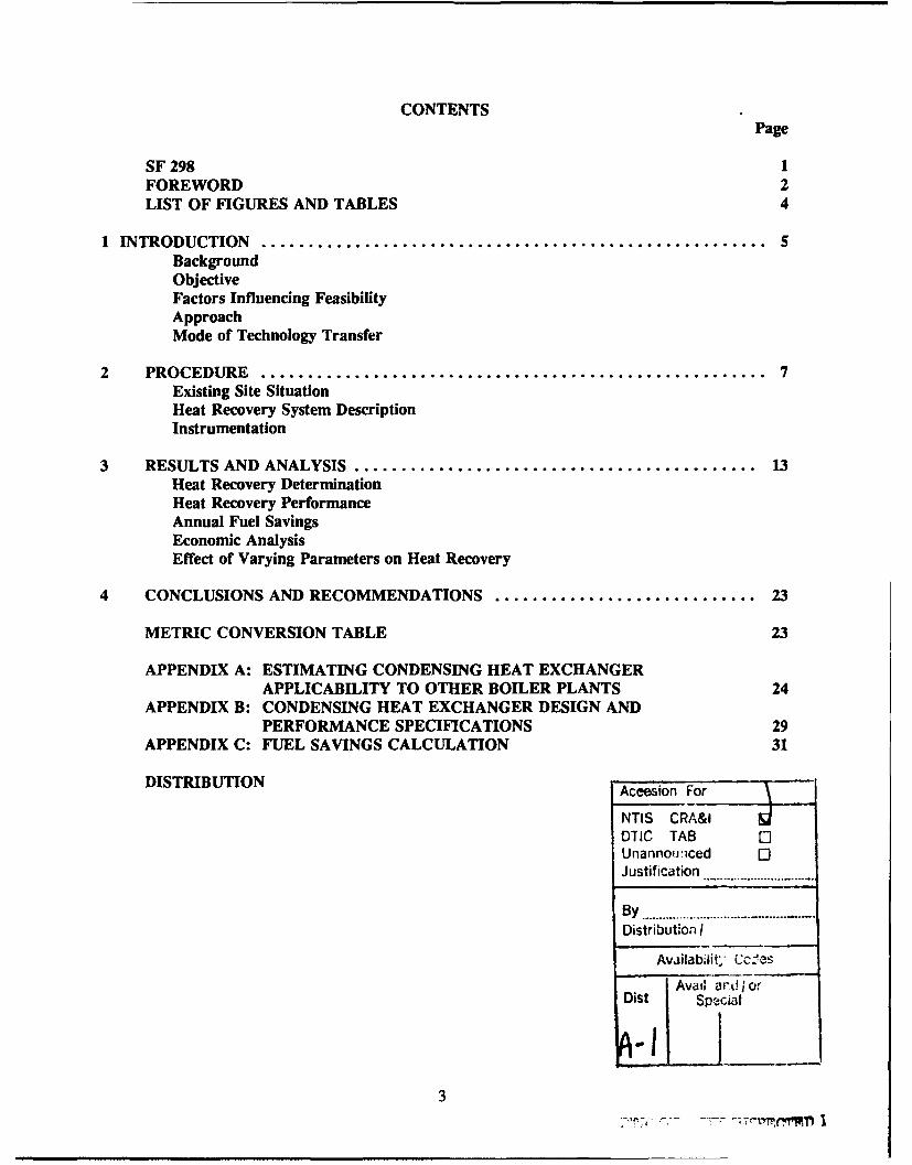
CONTENTSPage
SF 298 1FOREWORD 2LIST OF FIGURES AND TABLES 4
1 INTRODUCTION ...................................................... 5BackgroundObjectiveFactors Influencing FeasibilityApproachMode of Technology Transfer
2 PROCEDURE ...................................................... 7Existing Site SituationHeat Recovery System DescriptionInstrumentation
3 RESULTS AND ANALYSIS ........................................... 13Heat Recovery DeterminationHeat Recovery PerformanceAnnual Fuel SavingsEconomic AnalysisEffect of Varying Parameters on Heat Recovery
4 CONCLUSIONS AND RECOMMENDATIONS ............................ 23
METRIC CONVERSION TABLE 23
APPENDIX A: ESTIMATING CONDENSING HEAT EXCHANGERAPPLICABILITY TO OTHER BOILER PLANTS 24
APPENDIX B: CONDENSING HEAT EXCHANGER DESIGN ANDPERFORMANCE SPECIFICATIONS 29
APPENDIX C: FUEL SAVINGS CALCULATION 31
DISTRIBUTION Aceesion For
NTIS CRAMDTIC TAB [Unannounlced I-Justification .................................
By ................................ ......... •..
Distribution I
Availability ,..SAvai; ard I'J or
Dist pca
3

FIGURES
Number Page
1 Existing Site Schematic 7
2 Site Schematic With CHE Installed 10
3 Sample Data Sheet 12
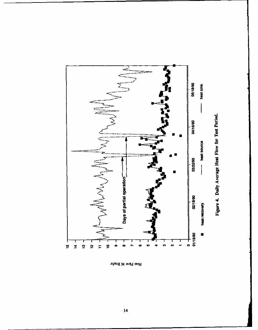
4 Daily Average Heat Flow for Test Period 14
5 Heat Recovery vs Average Temperature 16
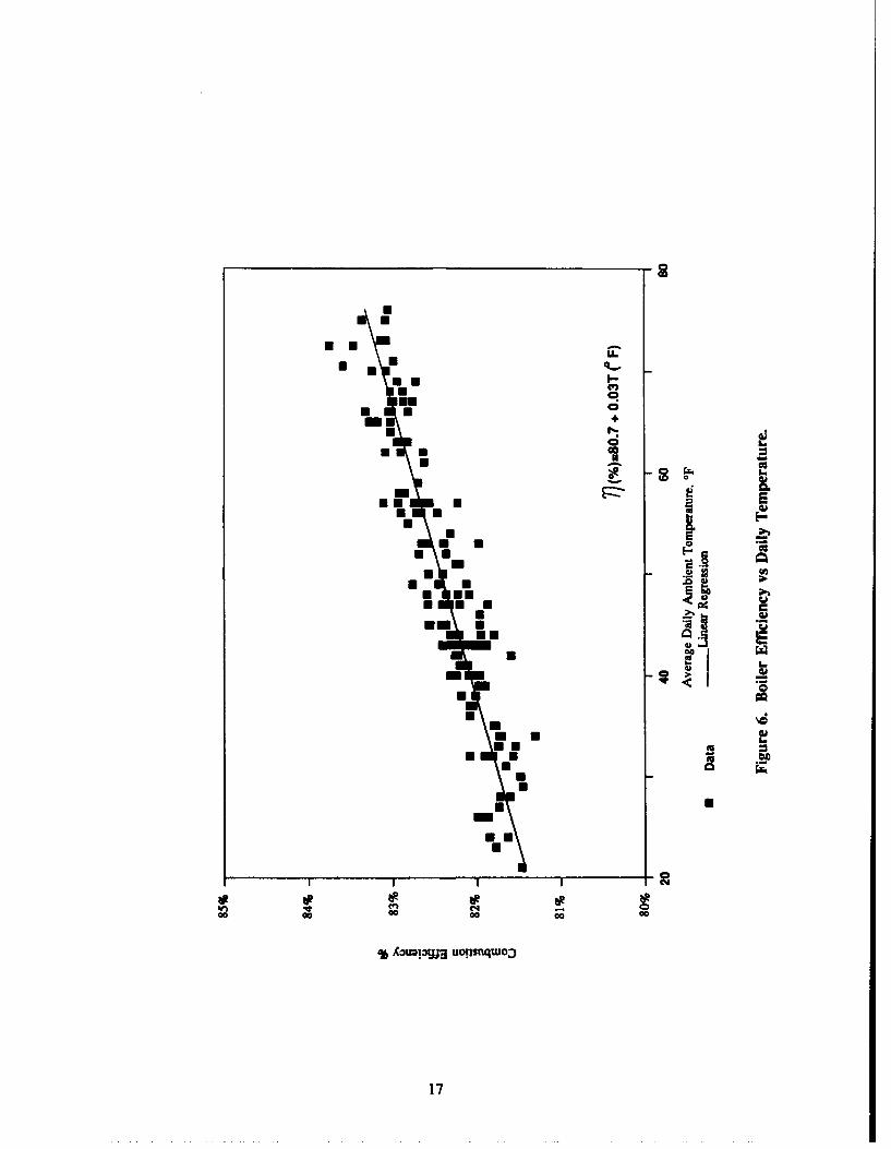
6 Boiler Efficiency vs Daily Temperature 17
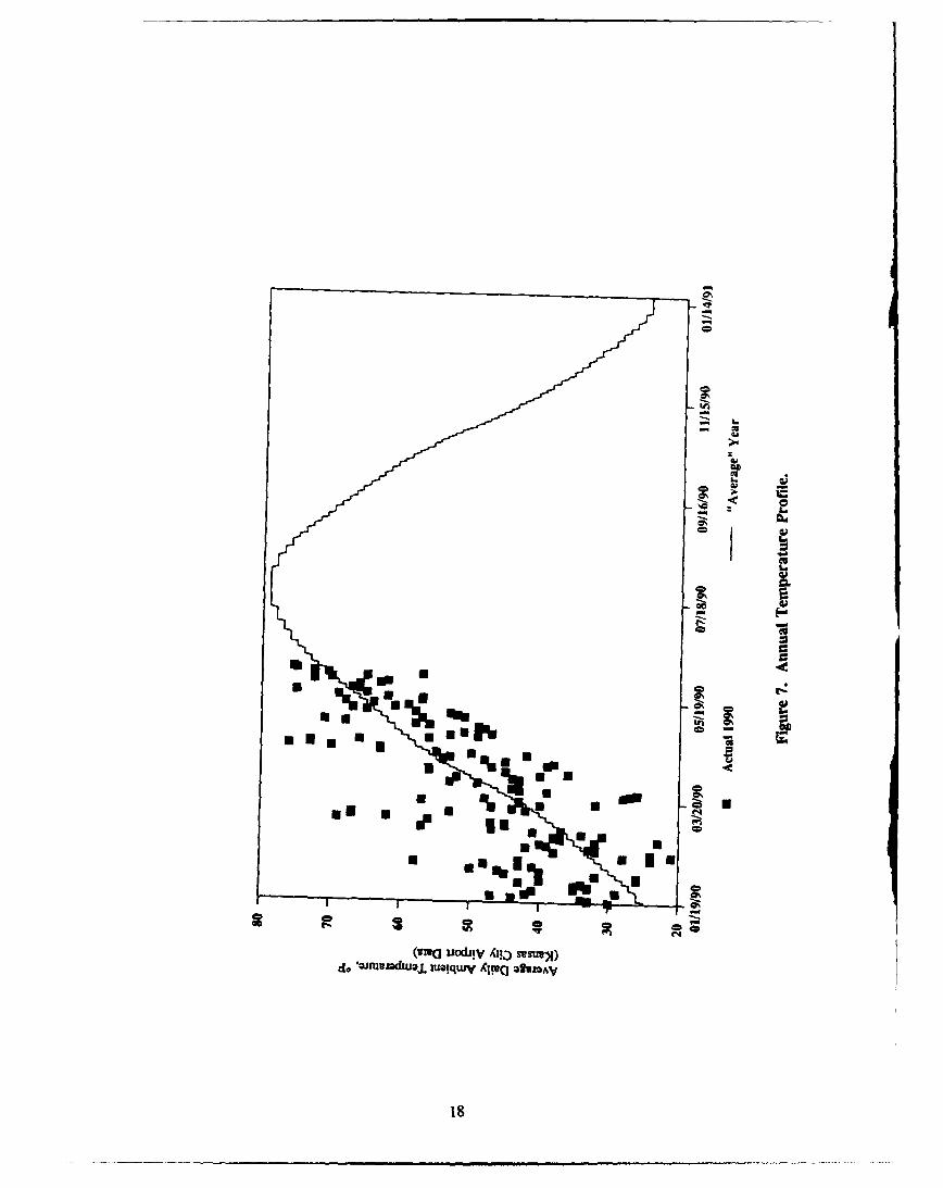
7 Annual Temperature Profile 18
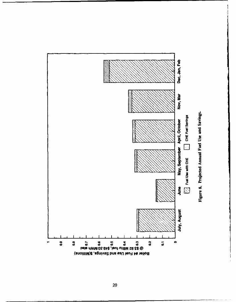
8 Projected Annual Fuel Use and Savings 20
9 Heat Recovery Variation With Flow Rate, Temperature 22
C1 Example Boiler System 31
TABLES
1 Measured Performance During Test Period 15
2 Projected Annual Performance 21
3 Original Performance Estimates 21
Al Ieat Source Determination 25
A2 Heat Sink Determination 26
A3 Energy Savings Determination 27
A4 Cost and Savings Expected for Hypothetical Applications 28
4
PERFORMANCE OF A CONDENSING HEAT EXCHANGER SYSTEM AT LAKE CITY ARMYAMMUNITION PLANT, INDEPENDENCE, MO
1 INTRODUCTION
Background
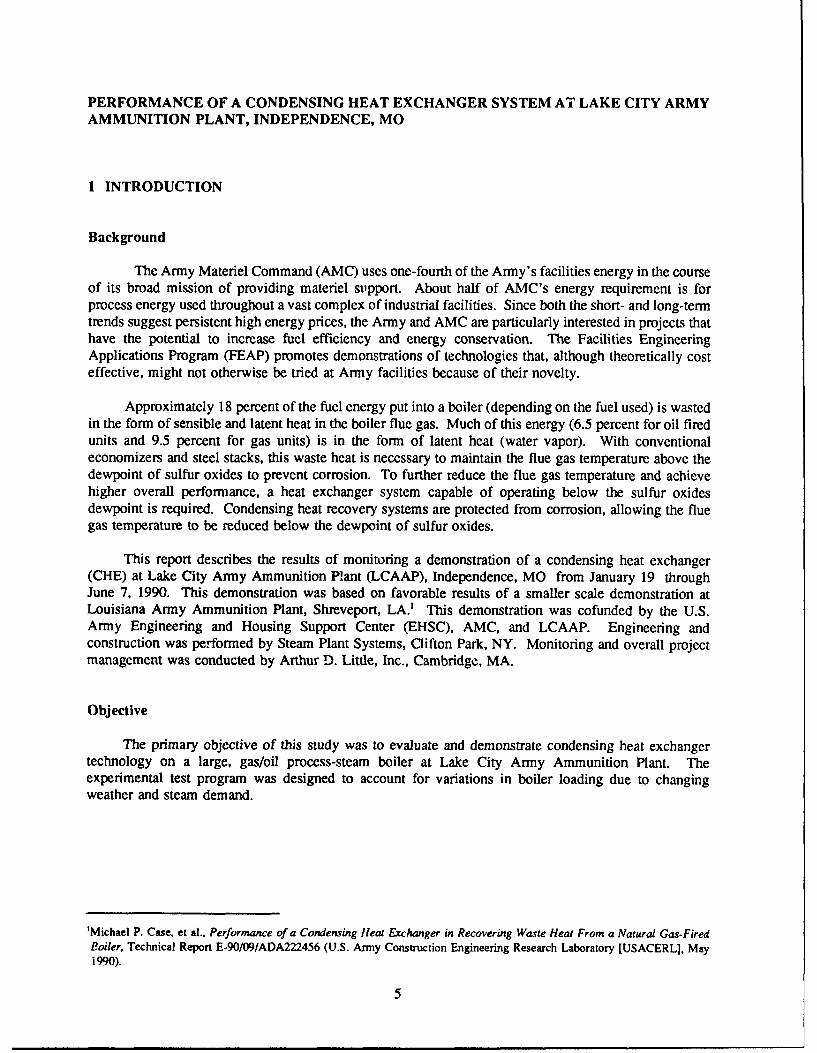
The Army Materiel Command (AMC) uses one-fourth of the Army's facilities energy in the courseof its broad mission of providing materiel support. About half of AMC's energy requirement is forprocess energy used throughout a vast complex of industrial facilities. Since both the short- and long-termtrends suggest persistent high energy prices, the Army and AMC are particularly interested in projects thathave the potential to increase fuel efficiency and energy conservation. The Facilities EngineeringApplications Program (FEAP) promotes demonstrations of technologies that, although theoretically costeffective, might not otherwise be tried at Army facilities because of their novelty.
Approximately 18 percent of the fuel energy put into a boiler (depending on the fuel used) is wastedin the form of sensible and latent heat in the boiler flue gas. Much of this energy (6.5 percent for oil firedunits and 9.5 percent for gas units) is in the form of latent heat (water vapor). With conventionaleconomizers and steel stacks, this waste heat is necessary to maintain the flue gas temperature above thedewpoint of sulfur oxides to prevent corrosion. To further reduce the flue gas temperature and achievehigher overall performance, a heat exchanger system capable of operating below the sulfur oxidesdewpoint is required. Condensing heat recovery systems are protected from corrosion, allowing the fluegas temperature to be reduced below the dewpoint of sulfur oxides.
This report describes the results of monitoring a demonstration of a condensing heat exchanger(CHE) at Lake City Army Ammunition Plant (LCAAP), Independence, MO from January 19 throughJune 7, 1990. This demonstration was based on favorable results of a smaller scale demonstration atLouisiana Army Ammunition Plant, Shreveport, LA.1 This demonstration was cofunded by the U.S.Army Engineering and Housing Support Center (EHSC), AMC, and LCAAP. Engineering andconstruction was performed by Steam Plant Systems, Clifton Park, NY. Monitoring and overall projectmanagement was conducted by Arthur D. Little, Inc., Cambridge, MA.
Objective
The primary objective of this study was to evaluate and demonstrate condensing heat exchangertechnology on a large, gas/oil process-steam boiler at Lake City Army Ammunition Plant. Theexperimental test program was designed to account for variations in boiler loading due to changingweather and steam demand.
'Michael P. Case, et al., Performance of a Condensing Heat Exchanger in Recovering Waste Heat From a Natural Gas-FiredBoiler, Technical Report E-90/09/ADA222456 (U.S. Army Construction Engineering Research Laboratory [USACERL], May1990).
5
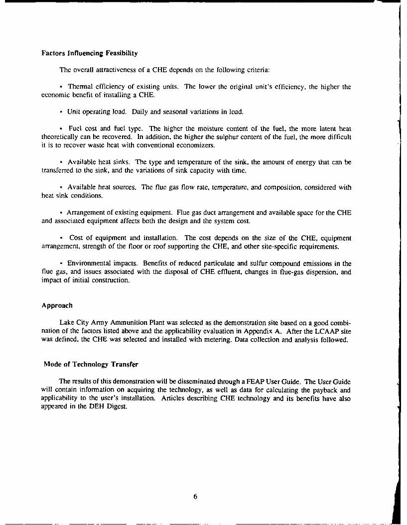
Factors Influencing Feasibility
The overall attractiveness of a CHE depends on the following criteria:
0 Thermal efficiency of existing units. The lower the original unit's efficiency, the higher theeconomic benefit of installing a CHE.
"* Unit operating load. Daily and seasonal variations in load.
"* Fuel cost and fuel type. The higher the moisture content of the fuel, the more latent heattheoretically can be recovered. In addition, the higher the sulphur content of the fuel, the more difficultit is to recover waste heat with conventional economizers.
0 Available heat sinks. The type and temperature of the sink, the amount of energy that can betransferred to the sink, and the variations of sink capacity with time.
. Available heat sources. The flue gas flow rate, temperature, and composition, considered withheat sink conditions.
- Arrangement of existing equipment. Flue gas duct arrangement and available space for the CHEand associated equipment affects both the design and the system cost.
0 Cost of equipment and installation. The cost depends on the size of the CHE, equipmentarrangement, strength of the floor or roof supporting the CHE, and other site-specific requirements.
. Environmental impacts. Benefits of reduced particulate and sulfur compound emissions in theflue gas, and issues associated with the disposal of CHE effluent, changes in flue-gas dispersion, andimpact of initial construction.
Approach
Lake City Army Ammunition Plant was selected as the demonstration site based on a good combi-nation of the factors listed above and the applicability evaluation in Appendix A. After the LCAAP sitewas defined, the CHE was selected and installed with metering. Data collection and analysis followed.
Mode of Technology Transfer
The results of this demonstration will be disseminated through a FEAP User Guide. The User Guidewill contain information on acquiring the technology, as well as data for calculating the payback andapplicability to the user's installation. Articles describing CHE technology and its benefits have alsoappeared in the DEH Digest.
6
2 PROCEDURE
Existing Site Situation
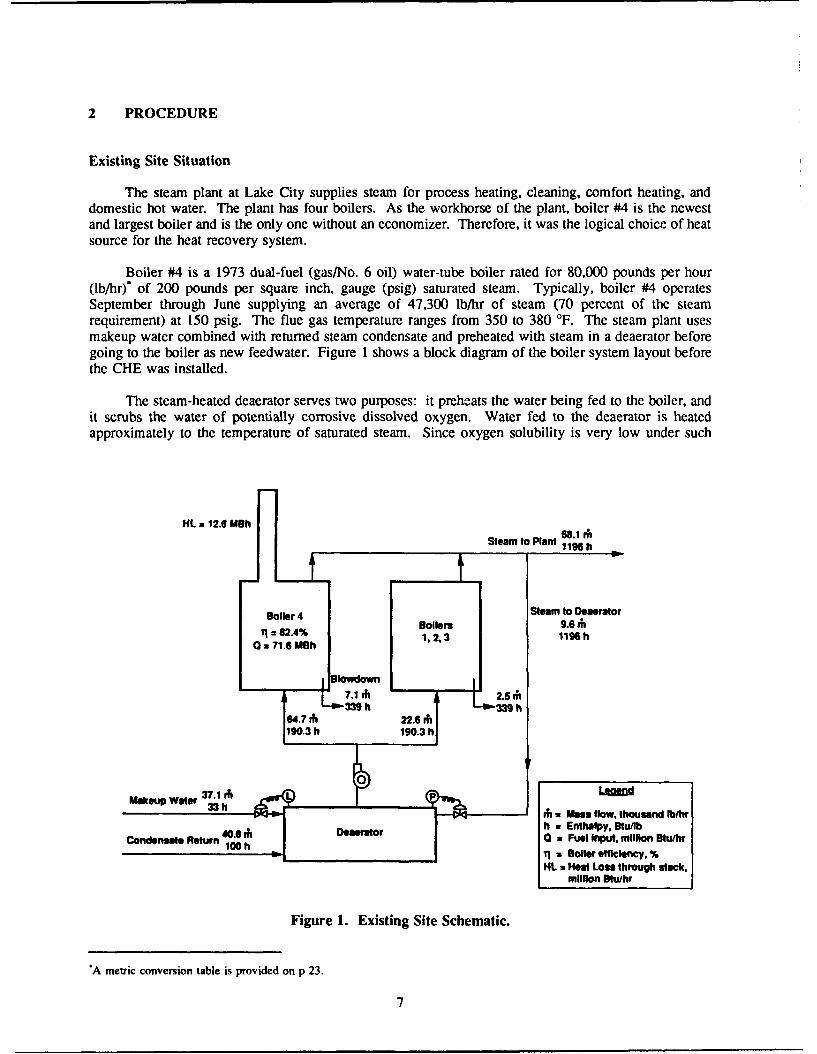
The steam plant at Lake City supplies steam for process heating, cleaning, comfort heating, anddomestic hot water. The plant has four boilers. As the workhorse of the plant, boiler #4 is the newestand largest boiler and is the only one without an economizer. Therefore, it was the logical choice of heatsource for the heat recovery system.
Boiler #4 is a 1973 dual-fuel (gas/No. 6 oil) water-tube boiler rated for 80,000 pounds per hour(lb/hr) of 200 pounds per square inch, gauge (psig) saturated steam. Typically, boiler #4 operatesSeptember through June supplying an average of 47,300 lb/hr of steam (70 percent of the steamrequirement) at 150 psig. The flue gas temperature ranges from 350 to 380 'F. The steam plant usesmakeup water combined with returned steam condensate and preheated with steam in a deaerator beforegoing to the boiler as new feedwater. Figure 1 shows a block diagram of the boiler system layout beforethe CHE was installed.
The steam-heated deaerator serves two purposes: it preheats the water being fed to the boiler, andit scrubs the water of potentially corrosive dissolved oxygen. Water fed to the deaerator is heatedapproximately to the temperature of saturated steam. Since oxygen solubility is very low under such
HL =12.6 MBh• 81I
Steam to Plant 11961 h
Boiler 4 Steam to DeseratorBoilers 9.6 ii
T0 = 71.4%N 1, 2, 3 1196 h
I lowdown17.1 rh2.,c
6 4.7 , -63M39 h D2. " O339 h
190.3 h 190.3 h
t 33 h h a Mass flow, thousand Ibhrnn eu40.6 rh Oesor h z Enthalpy, Btu/fb
0 a Fuel Input, million Btu/hr100_h1 7 __ = Boiler officlency, %
HL = Heat Loss through stock,million Btlhr
Figure 1. Existing Site Schematic.
"A metric conversion table is provided on p 23.
7

conditions, 97 to 98 percent of the oxygen is released to the steam and then vented away. The deaeratedwater is then suitable for feeding the boiler. The CHE reduces the steam required for the deacrator bysupplying it with preheated makeup water.
Heat Recovery System Description
The heat recovery system consists of a heat exchanger, supply and return water piping, supplyducting with a damper and fan, an exhaust stack, and necessary controls for operation.
Condensing Heat Exchanger Overview
The condensing heat exchanger is a mechanical unit that uses the waste heat in the boiler flue gasto preheat boiler makeup water. The flue gas flows over tubes that carry the makeup water to be heated.The quantity of heat transferred is limited by the heat available from the flue gas and/or the heatrequirement of the makeup water.
A CHE is ideal for this application because it can take advantage of waste heat below the sulfurdewpoint temperature, since it is coated and can tolerate the corrosive effects of condensing flue gas. Thesystem can therefore cool the flue gas below its dewpoint, permitting latent heat extraction from the watervapor present in the flue gas.
Heat transfer depends on the temperatures, flow rates, and heat transfer coefficients of the heat sinkand heat source. The most effective combination takes maximum advantage of these factors. The boilerflue gas, as the heat source, is relatively well defined; the challenge is to find available heat sinks that caneffectively use the recovered heat stream.
Since liquids have higher heat capacities and heat transfer coefficients than gases, the most desirableheat sink is typically the lowest-temperature water available at a reasonable flow rate. Therefore, makeupwater is often the first choice of heat sink for condensing heat recovery. However, if there is substantialcondensate return, the makeup water flow rate may not be conducive to cost-effective heat recovery.
Combustion air can also be preheated via condensing heat recovery, but this option generally is notas attractive as preheating makeup water or other liquids. The low heat capacity of air and the smallerheat transfer coefficient necessitate larger, more expensive heat exch:,ngers to accommodate both the heat-transfer surface requirements and the large volume of combustion air. Additional problems are presentedby requirements for large and often lengthy ductwork, or in some cases, use of paired exchangers.
In the LCAAP application, makeup water was readily available at flow rates of 50 to 100 gpm andrelatively low temperatures of approximately 65 'F to use as a heat sink. Makeup water for the steamplant housing four boilers was preheated using the flue gas from boiler #4.
Heat Exchanger Selection
The CHE itself is the heart of the system and it's selection is critical to the life of the system.Condensing heat exchangers are designed to reduce the flue gas temperature to below 200 'F, a pointwhere not only sulfuric acid (if sulfur is present in the fuel) but also water vapor condenses on the tubescreating a highly corrosive environment. The challenge of condensing heat recovery is to provide a heatexchanger that can withstand this environment.
Condensing heat exchangers on the market use glass, graphite, stainless steel, or Teflone to protectthe tubes (where most condensation occurs) and glass, stainless steel, or Teflono to protect the shell of theheat exchanger from corrosive attack.
8

Glass (Pyrex®) exchangers have a good track record; however, glass tubes might break due to thepressure difference between the water inside the tubes (-60 psig) and the gas outside the tubes.
Graphite-Viton exchangers introduced in 1987, appear promising. Although researchers selecteda proven performer for this demonstration, future efforts should investigate graphitc-Viton exchangers.
Stainless steel exchangers are offered by one company. The heat exchanger has promise, and themanufacturer has significant experience in the chemical process industry, but has little experience withboiler flue gas. The manufacturer's lack of experience with boiler systems would increase the designeffort and the risk of inadequate system design. This system requires further study to determineacceptability to condensing flue gas heat recovery.
The heat exchanger chosen for this FEAP demonstration is a Teflon--Teflon exchanger suppliedby CHX® Corporation, Wamerville, NY. The tubes and shell are Teflon covered. The CHX® heatexchanger is 12 ft high by 5.3 ft deep by 4.8 ft wide, and provides a heat transfer surface area of 1590sq ft. It weighs 6772 lb when empty and 9017 lb with water in the tubes. The unit is composed of fivemodules each with 240 horizontal tubes in an 8 by 30 arrangement; each tube is 60 in. long. Minimumwater flow rate is 22.5 gallons per minute (gpm). Se: Appendix B for complete CHX0 specifications.
Flue Gas Flow
Figure 2 shows a simplified schematic of the installation arrangement with the CHE in place. Theflue gas enters the heat recovery system through a new breaching in the existing stack, then flows pasta flue-gas damper, through an induced draft fan, down through the heat exchanger, and exits up througha fiberglass-reinforced plastic stack.
The damper controls flue-gas flow through the CHE to maintain the exit water setpoint temperature.If there is more flue gas available than needed to heat the makeup water fully, the excess flue gascontinues up the preexisting stack. Otherwise, all of the flue gas flows through the CHE and a smallamount of outside air is drawn down the preexisting stack. The fan is provided to overcome the pressuredrop through the heat recovery system. This is a passive system since no obstruction is placed in theexisting flue-gas passages. This damper also shuts down at a high flue gas inlet temperature (setpoint =450 OF) due to the maximum temperature limit of the Teflon.
A drain is provided on the flue gas side for the water vapor and acids that condense on the CHEtubes. The condensate and the CHE washwater are highly acidic and cannot typically be drained to asewer because of their corrosiveness. Commonly accepted practice is to pipe the CHE drain to the boilerblowdown sump since boiler blowdown is highly alkaline and neutralizes the condensate. Note thatenvironmental regulators generally establish thermal and chemical property limitations on wastewatereffluents at the point of discharge. Typically, the CHE condensate is so small as to be negligible whencombined with other wastewater effluents. However, local regulations may vary and some may requireCHE condensate pretreatment.
Makeup Water Flow
On the water side, a booster pump overcomes the additional pressure drop of the CHE and itsassociated piping. The water outlet temperature setpoint is 160 OF to ensure that water to the deaeratoris not overheated. Furthermore, at high exit-water temperature (180 OF) the entire system shuts down toprotect the heat exchanger from steaming, over-pressure, or scale buildup on the tube side.
The system also shuts down on low water flow. In a low-flow or no-flow condition, the high exit-water temperature measurement may not accurately indicate the temperature of water in the tubes sincethe water further upstream could be at a higher temperature than the water in the outlet manifold.
9

b.
E
0
o= ELC 9_
*E mCU Cu 0) 0
co (P =EC Z0 0
0 lm
E sUV)
q~~inC C4)(ICU
cm CD
Cu 8)
C0 4j
These controls require that special care be taken in the system design to provide adequate water flowand prevent nuisance shutdowns. One issue addressed at Lake City was that condensate is returned to theboiler plant in surges caused by the cycling of large condensate return pumps. This causes the levelcontrol on the deaerator to briefly shut off the makeup water flow, which interrupts the flow of wate.r tothe heat exchanger. The situation was intermittent, but it could occur several times an hour.
One approach to preventing frequent shutdowns is to install a storage tank and circulating waterloop. For this demonstration, researchers pursued a less costly approach consisting of installing a bypassline around the makeup water control valve to allow a small amount of makeup water (approximately 22gpm) to flow continuously through the CHE and into the deaerator. This approach, however, inherentlyhas the risk of overflowing the deacrator. There were already two sources of uncontrolled water flow tothe deaerator (condensate return and boiler feed-pump turbine steam discharge); now there are three. Sofar, researchers have not observed a problem of water overflow from the deaerator. However, on a fewwarm days in early June 1990, the steam requirement of the deaerator, with preheated makeup water fromthe CHE, was less than the steam discharge from the boiler fecd-pump turbine. Rather than vent theexcess steam to tht atmosphere, researchers shut down the CHE so the boiler feed-pump turbine dischargesteam could be fully used.
The maximum water flow through the CHE is 125 gpm at a 20 psi pressure drop. This allows allof the makeup water to be preheated under usual circumstances. However, if all boilers were operatedat maximum output, such as might occur during mobilization, there would not be sufficient water flowthrough the CHE to satisfy the makeup water requirement. To accommodate this situation, researchersinstalled a pressure-activated bypass valve to bypass additional makeup water around the CHE in the eventof makeup water demand greater than 125 gpm.
Instrumentation
Heat recovery monitoring instrumentation consisted of a water meter, two thermistors, and a Btucomputer to calculate and display the cumulative flow and enthalpy increase of makeup water through theCHE.
The selected turbine water, a 3-in. Badger Turbo meter, provides a pulse output for each 10 galprocessed through the meter and is accurate to ± 0.5 percent over the range 60 to 350 gpm.
High precision thermistors were installed in the inlet and outlet water manifolds. These YSI brandthermistors (model 44036) are interchangeable to ±0.2 OF for a maximum measurement error of about 0.5percent on an 80 OF temperature differential.
The signals from the flow meter and the water inlet and exit thermistors are registered on a DKEnterprises Btu computer. An internal microprocessor with a digital staircase integrating board uses thisinformation to compute the Btu change in the flowing water stream within ±0.4 percent.
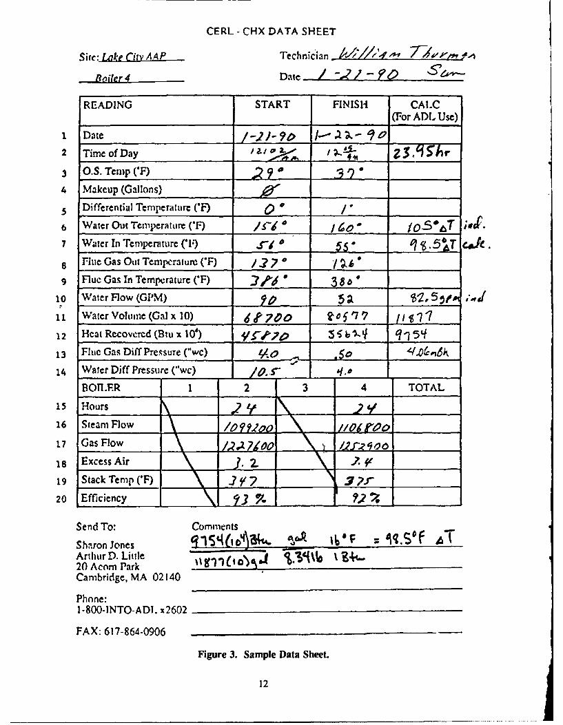
Lake City boiler operators recorded Btu meter, CHE, and boiler plant information daily. Data sheetswere collected at the site and transmitted to Arthur D. Little by telefax weekly. Figure 3 shows a sampledata sheet used during monitoring.
I1
CERL - CHX DATA SHEET
Site: LatLe City A.4P Technician ,-, 7 -,'"• v,- i
Bailer4 Date / -"-".
READING START FINISIi CAL.C(For ADL Use)
1 Date /-.2J- 9P --- 9o2 Time of Day IjI a ~ J 1 3._S';3 O.S. Temp (7) 2 ?
4 Makeup (Gallons)
5 Differential Temperature ('F) _ __'_/"
6 Water Out Temperature ('F) 11____1I / 1,60- j057 T "
7 Water In Temperature ('1) ,.€"_ _ $,_" 0 .5bT c4.8 Flue Gas Out Temperature ('F) 3.?7 / ,9 Flue Gas In Temperature ('F) -/6'. 3 $___"
1O Water Flow (GPM) 5 • $, 5 •f ,
11 Water Vohime (Gal x 10) 4t'7O0 to5 1,7 __/1
12 Hcat Recovered (Btu x l0) _______ 5 "______ q-7 5q
13 Fluc Gas Diff Pressure ("wc) ./o -
14 Water Diff Pressure ("wc) /0...._,
BOT. R 1 2 3 4 TOTAL
15 Hours .916 Steam Flow r'00___ //o~rao
17 GasFlow /) 12MOO L7d0 o _1____
18 Excess Air j. 2e __.2. _
19 Stack Tenip (F).2?'? 7r ___,_
20 Efficiency ?.2 _ __-_
Send To: Comments
Sharon Jones 1 ______ = %q.S'f ATArthur D. Little " %.40 -20 Acorn Park _ _ _ _ _ _ _ _ _ _ _ _ _ _ __,
Cambridge, MA 02140
Phone:
1-800-INTO-ADI. x2602
FAX: 617-864-0906
Figure 3. Sample Data Sheet.
12
3 RESULTS AND ANALYSIS
Heat Recovery Iktermination
The degree of makeup water preheat achieved is a direct function of the heat transferred orrecovered. Heat recovery may be determined either from the loss of the heat source or the gain of theheat sink, both of which are a function of temperature and flow. For this study, researchers calculatedthe heat gain because the flow rate of water can be measured more easily and accurately than the flowrate of flue gas.
By measuring the flow rate and the temperature differential across the condensing heat exchanger,and combining the results of these measurements with the known density and heat capacity of water,researchers calculated the amount of heat recovered.
Heat Recovery Performance
The Lake City installation is limited by the heat sink, as shown in Figure 4. In this figure, the heatsource is calculated as the heat available in the flue gas based on combustion efficiency. The calculationsshow that the heat sink raises the makeup water temperature by 95 OF, from 65 OF to 160 OF. Sitepersonnel selected 160 OF as the makeup water preheat temperature setpoint to ensure adequate steamloading in the deaerator for proper deaeration.
A tabulation of the results of heat recovery monitoring over the test period is presented in Table 1for six bins of outdoor air temperature.
Over the test period (January 19 to June 7, 1990), the CHE produced an average of 3.2 millionBtu/hr heat recovery from the 55.8 million Btu/hr fuel consumed by boiler #4, to support 68,100 lb/hrsteam generation (covering the total plant).
Characteristics of the heat exchanger are as follows:
"* Reduces bulk flue gas temperature from 365 OF to 127 'F,
"* Preheats 74 gpm of makeup water from 65 OF to 160 OF,
"* Transfers 3500 kBtu/hr of sensible heat and 1475 kBtu/hr of latent heat,
"• Reduces steam flow to the deaerator by 38 percent.
Annual Fuel Savings
Since the heat recovered in the CHE preheats the incoming makeup water, this heat gain reducesthe steam load that the system must supply to the deaerator. This reduces the volume of water beingheated by the boiler, thereby saving fuel and a small amount of water that would otherwise be lost toblowdown. Consequently, fuel savings is based on the magnitude of the deaerator steam-load reduction.
The following equation (analytically derived in Appendix C), gives the daily fuel savings as afunction of the heat recovery makeup water flow rate, and existing boiler efficiency. (Later this equationis applied to account for a full, "average" year.)
13
4-n
------
"•. 0
<-• " i-
'- -
- S• '
. q/ ----- O. •
I-14
~ I
• u mmw~ u m m m m nU

Table 1
Measured Performance During Test Period
1 2 3 4 5 6
Outdoor temperature range, 'F 75T 70-74 62-69 50-61 37-49 36,1Avg. outdoor recorded temp., 'F 75.3 71.6 65.5 55.0 43.4 29.9Days in range 3 8 22 29 52 26
Heat sink: makeup waterFlow rate, gal/min 51.7 57.0 55.5 64.7 79.7 92.8Makeup water preheat, *F 89.4 97.5 96.5 95.9 93.2 95.3
Heat source: flue gasBoiler 4 steam load, lb/hr 39,600 40,000 43,000 48,800 49,700 52,400Existing efficiency. % 83.2 83.3 83.0 82.6 82.2 81.7
Heat Recovery, kBtu/hr 2300 2800 2700 3100 3700 4400
FS- [1.037H1R-0.116m 2] [Eq 1]
where FS = fuel savings, kBtu/hrHR = heat recovered, kBtu/hr11 = boiler efficiencyM2 = makeup water flow rate, kph.
As stated previously, heat recovery (HR) is a function of makeup water flow and makeup water flowtends to decrease with increasing average daily temperature. These functions have been combined to yieldheat recovery as correlated to average daily temperature in Figure 5.
Boiler efficiency (ri) depends on average daily ambient temperature, since it varies with excess airlevel, the entering combustion air temperature, and the exiting flue gas temperature (measured before theCHE). Figure 6 shows the corresponding relationship between boiler efficiency and temperature.
To determine annual fuel savings, researchers used the heat recovery/daily temperature correlationto extrapolate measured data from the 5-month test run to a full year's operation. Since changes in outsidetemperature affect the overall steam-load requirements, researchers applied the results to the temperatureprofile for an averaged "normal" year (Figure 7) and obtained the total fuel consumption/savingsachievable over a full year.
Economic Analysis
Using these correlations, annual fuel savings are expected to reach 36,000 million Btu/yr.
Cost savings are calculated from the fuel savings, valued at the cost of fuel, then discounted by theparasitic energy consumption of the supporting fan and pump valued at the cost of electricity. Fan power
15

U-* a
*U,* I.0
UU
U 'ft'Ib.- U
Em aS- a-
U.mU 2
* U* U HUE
U U* 0 C 41*
U - U
* .� Umm
* EU '1U U **
EU. ** U U
mum * wi- mu -
U EUU
* U Ii.)
* U aD* I-*EU 0
* ! E�*U
UU. UU
UU
g'a 'a 0 C4 0
JIJ/fl3fl jjj £JaAO�O�J )'�H
16
U. 0-
m m
a'* Go
U0c 0c
%,(*toW3uonsqw6
17 2
0C
0V
- a. E
lb0
rb'
Pta(=a iodjtVAlla sm4'
'aim zdu~jL uo~urVAIT4 221*A
18C

is estimated from the theoretical fan power requirement, which varies from 2 to 23 horsepower (hp), plus2 hp to conservatively account for motor inefficiency and shaft losses. Pump power is estimated at aconstant 1.5 hp.
With the 1990 price of fuel at LCAAP of $3.92/million Btu and of electricity at $49.50/MWh, thenet savings is $132,000/yr, as shown in Figure 8 and detailed in Table 2.
Referring to Arthur D. Little's preliminary design (see Table 3), the projected net savings of$132,000 per year exceeds the original estimate of $84,310 by 50 percent. This can be attributed toincreased fuel cost (40 percent increase) and future planned summer operation (12 percent increase). Thethermal performance of the heat exchanger was very close to predicted values.
Simple Payback. Total cost of the installed project was $199,200 excluding monitoring andreporting efforts. With annual savings of $132,000, the simple payback is 1.5 years.
Life Cycle Cost. The CHE system is expected to last 15 to 25 years. The net present value ofsavings based on a 15-year life is estimated at $852,700 using a 9 percent discount rate and assumingaverage maintenance costs over the life of the system of $1500 per year.
Effect of Varying Parameters on Heat Recovery
The key factors affecting heat recovery performance are associated with the heat sink (makeupwater) since this installation is heat sink limited. These factors are the flow rate and the maximumpermissible exit-water temperature. The following sensitivity analysis indicates how these key parametersaffect heat recovery.
The Lake City AAP steam plant averaged 73 gpm makeup water flow with 46 percent condensatereturn during the test period. Should the steam load or percent makeup increase, heat recovery increasescorrespondingly. Figure 9 shows how a change in makeup flow would affect heat recovery on anormalized basis. The figure shows that an increase in makeup water flow from 73 to 80 gpm wouldincrease heat recovery and fuel savings by 10 percent.
Researchers selected the maximum permissible exit-water temperature to be 160 OF. This couldrealistically be raised to 180 OF without damage to the CHE tubes. Figure 9 also shows that increasingthe exit water temperature from 160 OF to 180 OF would result in a 21 percent increase in heat recoveryand fuel savings. The site personnel are still evaluating the operational implications of increasing exitwater to 180 OF and realizing additional savings.
19
LU?0
zL
El
I L I aoa ~ ~~~~ *ý I ? I C r
c; 0 a 0 0 000104MMO&S lenjnjqR Z6C$,
(SU~jjjjM)'S6Uj8Spu -sln V#j0l
20C

Table 2Projected Annual Performance
July Sept Apr Nov Dec, JanAug June May Oct Mar Feb
Approx. Temp. range OF 75T 70-74 62-69 50-61 37-49 36,1
Average daily temp. 77.6 73.6 66.5 56.2 38.8 29.7
Days in period 62 30 61 61 61 90
Heat sink: makeup water
Flow rate. gal/min 44.6 48.6 55.8 66.2 83.7 92.8
Water preheat, OF 95 95 95 95.5 94.7 94.3
Heat recovery, kBtu/hr 2120* 2310 2650 3160 3960 4400
Fuel savings, MBtu/yr 3920* 2080 4850 5820 7340 12,010
Auxiliary energy, MWh/yr 9.4 4.6 9.3 28.9 28.0 42.7
Net fuel savings, $/yr** 14,200* 7500 17,700 20,300 27,300 45,000
*Savings depend on replacement of the BFP turbine with an electrical motor drive as planned for FY91.
**@$3.92/million Btu, $49.5/MWh
Table 3Original Performance Estimates
July June Sept, Apr, Nov-Aug May Oct Mar
Heat sink: makeup waterFlow rate, gal/min N/A 50 70 80 90Makeup water preheat OF N/A 82 75 91 83
Heat Source: flue gasBoiler 4 steam load, lb/hr 0 20,000 30,000 55,000 75,000Existing efficiency, % N/A 78.9 80.1 80.2 80.5
Heat recovery, kBtu/hr 0 2100 2600 3600 3700
Annual operation, days/yr 62 30 61 61 151Annual heat recovery, MBtu 0 1480 3920 5310 13,470Annual fuel savings, MBtu 0 1875 4900 6620 16,730Annual savings @ $2.80/MBtu 0 $5250 $13,720 $18,540 $46,800
21

U..
E
222
4 CONCLUSIONS AND RECOMMENDATIONS
The demonstration of the Condensing Heat Exchanger system at LCAAP was highly successful.The system has a simple payback of 1.5 years (p 19), with a net annual fuel savings of $132,000 (Table2). This demonstration has also shown that the CHE system can be installed on a boiler that bums No.6 fuel oil. The ability to work with fuel cil is consistent with the manufacturer's report that approximately80 percent of the installed systems are on boilers burning No. 6 fuel oil.
It is important to perform standard "housekeeping" and ensure that the boiler has been tuned-upbefore installing heat recovery systems. Although a waste heat recovery device will show higher savingswhen boiler efficiency is low, it is preferable that the fuel not be wasted on the front end.
It is recommended that the procedure for evaluating potential installations of CHE systems befollowed as outlined in the Appendix to USACERL Technical Report E-90/09, Performance of aCondensing Heat Exchanger in Recovering Waste Heat From a Natural Gas-Fired Boiler.
METRIC CONVERSION TABLE
1 Btu = 352g-cal1 ft = 0.305mI gal = 3.78LI gal/min = 0.063084/SI in = 25.4mm1 lb = 0.453 kg1 lb/hr = 0.126 g/sI psi = 89.300 g/cm2
1 sq ft = 0.093m2
0.55(OF-32) = *C
23

APPENDIX A: ESTIMATING CONDENSING HEAT EXCHANGERAPPLICABILITY TO OTHER BOILER PLANTS
Many boiler plants within the U.S. Army could benefit from adding a condensing heat exchangerwaste heat recovery system. Boilers without economizers and little or no condensate return offer thegreatest potential for heat recovery. Evaluation of a potential condensing heat exchanger applicationfollows a simple four-step process:
1. Identify heat sources
?. Identify heat sinks
3. Match loads
4. Calculate savings and simple payback.
The procedure outlined below gives a preliminary evaluation of whether a potential application isworth further consideration. If so, a more detailed analysis should be performed.
Identify Heat Sources
When fuel is burned in a boiler, a major part of the heat produced is used to generate steam, anda smaller part is lost by conduction through the boiler walls, or is exhausted in the flue gases. The boilerefficiency varies according to the steam demand and allows one to determine how much of the suppliedfuel is converted to steam. For a first pass analysis, losses through the boiler walls can be neglected andthe heat losses quantified as whatever is not converted into steam. Although this will overstate the amountof heat available, the result is still useful in determining whlether further analysis should occur. If theresults of this analysis indicate a cost effective project, a more detailed analysis may be conducted.
For example, the load profile of a boiler has been divided into winter and summer bins of similarboiler efficiences (Table Al). For instance, a boiler might normally operate at two firing rates, with asummer average boiler efficiency of 80 percent and a winter efficiency of 76 percent. The energy avail-able for each bin (QH) is a function of fuel use rate (Fin), boiler efficiency (ilB), and operating hours (AT):
Q1 - F1nAT(1 - f11) [Eq All
Table Al shows that for this example problem, the energy available in the winter bin is 19,443MBtu and in the summer bin is 7647 MBtu. This example assumes that only the heat from one boilerwould be recovered, but it is often the case that flue gases from two or more boilers could feasibly beducted to the same condensing heat exchanger.
Identify Heat Sinks
It is important to first identify liquid streams that could be heated with a condensing heat exchanger.In the case of a boiler with limited or no condensate return, the makeup feedwater stream is a goodcandidate. For cost efficiency, consider flows that pass through the boiler room or adjacent buildings
24
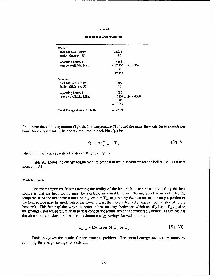
Table Al
Heat Source Determination
Winter:fuel use rate, kBtu/h 22,256boiler efficiecy (%) 80
operating hours, h 4368energy available, MBtu =-22,256 x .2 x 4368
1000= 19,443
Summer:fuel use rete, kBtu/h 7809boiler efficiency, (%) 76
operating hours, h 4080energy available, MBtu = 7809 x .24 x 4080
1000= 7647
Total Energy Available, MBtu = 27,090
first. Note the cold temperature (Ti,), the hot temperature (Tu), and the mass flow rate (m in pounds perhour) for each stream. The energy required in each bin (QL) is:
QL - mc(To.t - Tin) [Eq A]
where c = the heat capacity of water (I Btu/Ibm- deg F).
Table A2 shows the energy requirement to preheat makeup feedwater for the boiler used as a heatsource in Al.
Match Loads
The most important factor affecting the ability of the heat sink to use heat provided by the heatsource is that the heat source must be available in a usable form. To use an obvious example, thetemperature of the heat source must be higher than Tou, required by the heat source, or only a portion ofthe heat source may be used. Also, the lower Tou, is, the more effectively heat can be transferred to theheat sink. This fact explains why it is better to heat makeup feedwater, which usually has a Ti, equal tothe ground water temperature, than to heat condensate return, which is considerably hotter. Assuming thatthe above prerequisites are met, the maximum energy savings for each bin are:
Q.,,d - the lesser of QH or QL [Eq A3]
Table A3 gives the results for the example problem. The annual energy savings are found bysumming the energy savings for each bin.
25
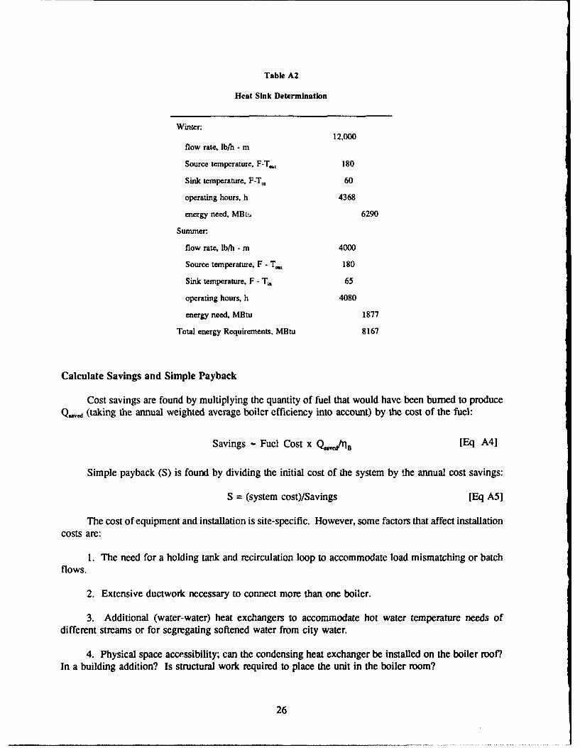
Table A2
Heat Sink Determination
Winter:12,000
flow rate, lb/h - m
Source temperature, F-Tc., 180
Sink temperature, F-Tm 60
operating hours, h 4368
energy need, MBt& 6290
Summer:
flow rate, lb/h - m 4000
Source temperature, F - T,., 180
Sink temperature, F - T,. 65
operating hours, h 4080
energy need, MBtu 1877
Total energy Requirements, MBtu 8167
Calculate Savings and Simple Payback
Cost savings are found by multiplying the quantity of fuel that would have been burned to produceQ,5 .d (taking the annual weighted average boiler efficiency into account) by the cost of the fuel:
Savings - Fuel Cost x QdIrla [Eq A4]
Simple payback (S) is found by dividing the initial cost of zhe system by the annual cost savings:
S = (system cost)/Savings [Eq A5]
The cost of equipment and installation is site-specific. However, some factors that affect installationcosts are:
1. The need for a holding tank and recirculation loop to accommodate load mismatching or batchflows.
2. Extensive ductwork necessary to connect more than one boiler.
3. Additional (water-water) heat exchangers to accommodate hot water temperature needs ofdifferent streams or for segregating softened water from city water.
4. Physical space accessibility; can the condensing heat exchanger be installed on the boiler roo?.In a building addition? Is structural work required to place the unit in the boiler room?
26

Table A3
Energy Savings Determination
Energy TransferWinter, MBtuminimum of [6290, 19443] 6290
Summer, MBtuminimum of [1877, 7647] 1877
Total Energy Requirements. MBtu 8167
Is Further Analysis Justified?
Generally, if the condensing heat exchanger application being considered has a simple payback ofless than 5 years, a more detailed analysis is highly recommended and the system has a high probabilityof providing a quick return on investment. If the simple payback is between 5 and 10 years, other factorssuch as the time value of money, fuel escalation rates, operating and maintenance costs, and salvage valuebecome more important. The Life Cycle Cost in Design (LCCID) program is the recommended methodof carrying out this analysis. It is available through the BLAST support office at the following address:
BLAST Support Office144 Mechanical Engineering Building
1206 West Green StreetUrbana, IL 61801
Other Examples
In the example given, only one boiler plant is serving as a heat source; the heat sink is the coldmakeup water serving the same boiler. Boiler loads are lighter in the summer, so less heat is availablefor recovery. Since less steam is required, less makeup water must be heated. Ground water temperatureis also higher in the summer, requiring less preheating before injection as makeup feedwater. In thewinter, the opposite is true, since high steam loads require large amounts of makeup feedwater. The loadsare well matched not only throughout the year, but also daily and hourly.
It is possible and often practical for a heat exchanger to recover waste heat from the flue gas ofseveral boilers and to use this heat to preheat not only makeup water, but also laundry water, domesticwater, and/or process water. Condensing heat exchangei applications have also included preheatingcombustion air, although this is less common. Table A4 gives sample calculations for four hypotheticalcases. Cases I and 2 are straightforward. Case 3 has an insufficient load to effectively use the heatavailable from the condensing heat exchanger. Case 4 depicts a system that uses the heat from one boilerto preheat feedwater for four boilers.
27
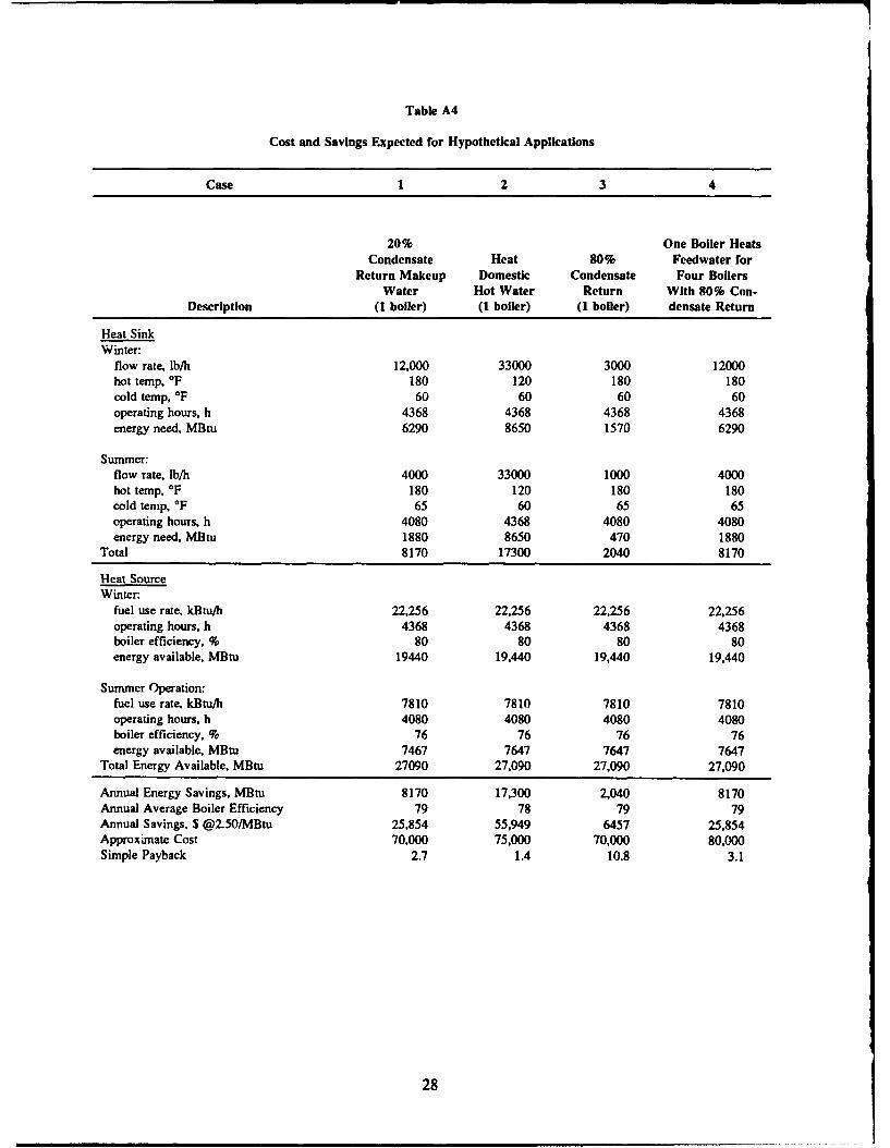
Table A4
Cost and Savings Expected for Hypothetical Applications
Case 1 2 3 4
20% One Boiler HeatsCondensate Heat 80% Feedwater for
Return Makeup Domestic Condensate Four BoilersWater Hot Water Return With 80% Con-
Description (1 boiler) (1 boiler) (1 boiler) densate Return
Heat SinkWinter:
flow rate, lb/h 12,000 33000 3000 12000hot temp, OF 180 120 180 180cold temp, OF 60 60 60 60operating hours, h 4368 4368 4368 4368energy need, MBtu 6290 8650 1570 6290
Summer:flow rate, lb/h 4000 33000 1000 4000hot temp, OF 180 120 180 180cold temp, OF 65 60 65 65operating hours, h 4080 4368 4080 4080energy need, MBtu 1880 8650 470 1880
Total 8170 17300 2040 8170
Heat SourceWinter:
fuel use rate, kBtu/h 22,256 22,256 22,256 22,256operating hours, h 4368 4368 4368 4368boiler efficiency. % 80 80 80 80energy available, MBtu 19440 19,440 19,440 19,440
Summer Operation:fuel use rate, kBtu/h 7810 7810 7810 7810operating hours, h 4080 4080 4080 4080boiler efficiency, % 76 76 76 76energy available, MBtu 7467 7647 7647 7647
Total Energy Available, MBtu 27090 27,090 27,090 27,090
Annual Energy Savings, MBtu 8170 17,300 2,040 8170Annual Average Boiler Efficiency 79 78 79 79Annual Savings, $ @2.50/MBtu 25,854 55,949 6457 25,854Approximate Cost 70,000 75,000 70,000 80,000Simple Payback 2.7 1.4 10.8 3.1
28

APPENDIX B: CONDENSING HEAT EXCHANGER DESIGN AND PERFORMANCESPECIFICATIONS
Condensing Heat Exchanger Physical Design Specifications
Model number 240-60 DW5Tube material Copper Alloy 706Tube specification ASTM-B 111Tube arrangement per module 8 x 30Number of modules 5Tube length 60 in.Tube size (O.D.) 1.125 in.Tube wall thickness 0.035 in.Design pressure 100 psig @ 200 IF water temperatureTest pressure 200 psig @ 100 IFDesign temperature 200 IF (water side), 500 IF (gas side)Shell casing material 10 gauge carbon steelTeflon covering 0.015 in. (on tube O.D.), 0.060 in. (on gas side ofshell)Heat exchanger height 12.0 ftHeat exchanger depth 5.3 ftHeat exchanger width 4.8 ftDry weight 6772 lbFlooded weight 9017 lbHeat exchanger surface area 1590 sq ftNumber of water manifold inlets/exits 15 connectionsMinimum allowable waterflow 42.5 gpmMaximum waterflow 125 gpm @ 20 psi
Performance Under Nominal Load Conditions for Test Period
Value SourceHeat sink:
waterflow through HX, gpm 73 Data averagewater inlet temperature, OF 65 Calculatedwater exit temperature, OF 160 Estimated from data
Heat Source:flue gas available, lb/hr 50,185 Calculated from dataflue gas flow through HX, lb/hr 40,150 Estimatedflue gas inlet Temperature, IF 365 Data averageflue gas exit temperature, IF 125 Estimated from datasteamload, lb/hr -
total plant 69,000 Data averagecorresponding, Boiler 4 48,200 Data averageminimum, Boiler 4 32,000 Calculated
29
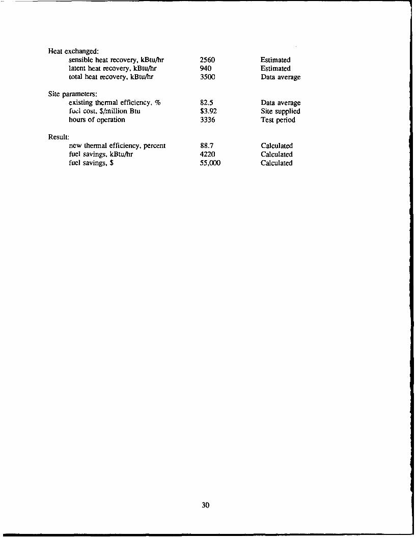
Heat exchanged:sensible heat recovery, kBtu/hr 2560 Estimatedlatent heat recovery, kBtu/hr 940 Estimatedtotal heat recovery, kBtu/hr 3500 Data average
Site parameters:existing thermal efficiency, % 82.5 Data averagefuel cost, $/million Btu $3.92 Site suppliedhours of operation 3336 Test period
Result:new thermal efficiency, percent 88.7 Calculatedfuel savings, kBtu/hr 4220 Calculatedfuel savings, $ 55,000 Calculated
30
APPENDIX C:
FUEL SAVINGS CALCULATION
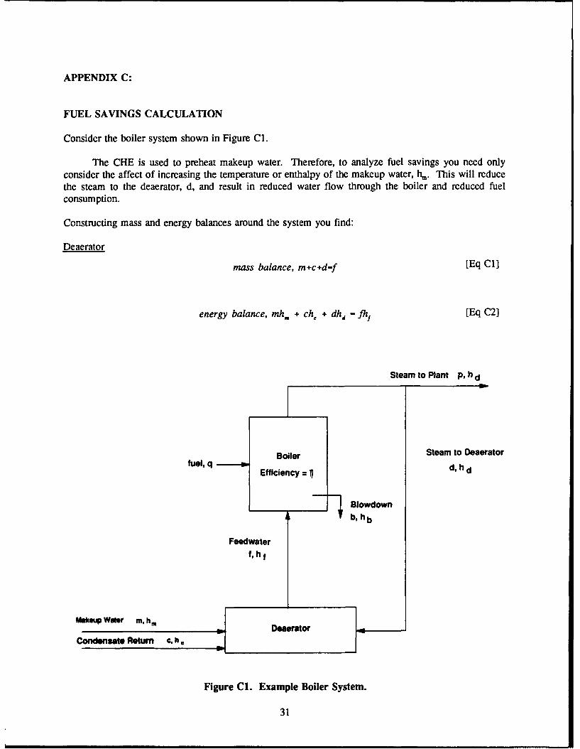
Consider the boiler system shown in Figure Cl.
The CHE is used to preheat makeup water. Therefore, to analyze fuel savings you need onlyconsider the affect of increasing the temperature or enthalpy of the makeup water, hm. This will reducethe steam to the deaerator, d, and result in reduced water flow through the boiler and reduced fuelconsumption.
Constructing mass and energy balances around the system you find:
Deaerator
mass balance, m+c+d-f [Eq C11
energy balance, mh. + ch. + dhd -I'fh [Eq C2]
Steam to Plant p, h d
Boiler Steam to Deaeratorfuel, q Efficiency = d, h d
Blowdownb, h b
Feedwaterf, hf
Make We m, Derator
Condensate Return €, h6
Figure C1. Example Boiler System.
31
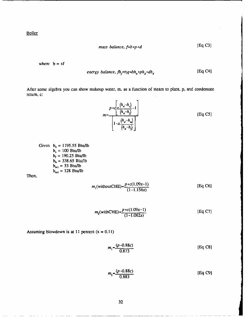
Boiler
mass balance, f-b+p+d [Eq C3]
where b = xf
energy balance, fhif+T1q-bhb+ph4 +dh4 [Eq C4]
After some algebra you can show makeup water, m, as a function of steam to plant, p, and condensate
return, c:
j h-h)
m (h-h) J [Eq C5]
(hd-h,)
Given hd = 1195.55 Btu/lbh, = 100 Btu/lbhf = 190.25 Btu/lbhb = 338.65 Btu/lbh., = 33 Btu/lbh.2 = 128 Btu/lb
Then,
mI(withoutCHE)- p ÷c(1.09x- 1) [Eq C61(1 -1.156x)
m2(withCHE)-P+C(l'O9x-l) [Eq C71(1 - 1.062x)
Assuming blowdown is at 11 percent (x = 0.11)
mi" (p-0.88c) [Eq C8]0.873
M2-,(p-0"88c) [Eq C910.883
32
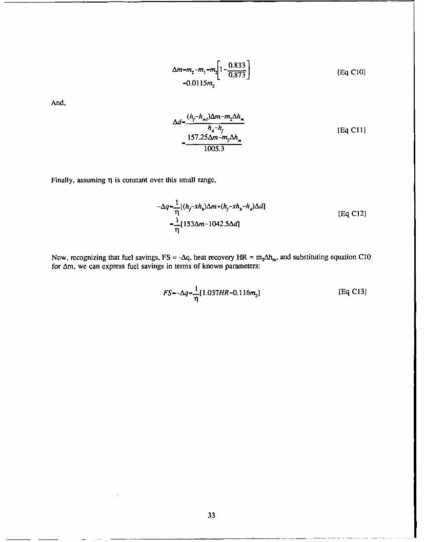
AM-r -mi- r. - 0.833] EqC
-0.01 15m 2
And,
Ad- (hf-h m)Am-m 2Ah,.hd-hf [Eq Cl I]
157.25Am-m 2Ah.
1005.3
Finally, assuming rl is constant over this small range,
-Aq-t[(hf-xh0)Am +(hf-xhb-h)d][ET1 [Eq C121
-I[153Am-1042.5Ad]T11
Now, recognizing that fuel savings, FS = -Aq, heat recovery HR = m2Ah1, and substituting equation CIOfor Am, we can express fuel savings in terms of known parameters:
FS--Aq-[ I[1.037HR-0.116m2] [Eq C13]
33
USACERL DISTRIBUTION
Chief of Engineers INSCOM - Chi, load. Div.AnIN: CEREC13-IM-LH (2) Arlington Hall Station 22212ArlN: CEHEC-IM-LP (2) ATMN Facilities Engineer (3)ATTN: CERD-L ATTN: Engr & Hag DivAflN: CECC-P Vint Hill Painam Stati-n 22186ATTN: CEC!W AMl: IAV-DEHATTN: CECW-OATM CEC7W-P USA AMCCOM 61299ArrN: CECW-RR AflN: AMSMC-ISAIIN: CEMP ATT'N: AMSMC-RIATTN: CEMP-EATTN: CEED TRADOC (19)AMN: CERD-C HQ, TRADOC. ATT7N: ATEN-DEN 23651ATTN: CERD-M ATTN: DEHATrN: CERMAMl: DAEN-ZCE USAISATTN: DAEN-ZCI Fort Huadioca 85613ATTN: DAEN-ZCM ATMN: Facilities Engineer (3)ATTN: DAEN-ZCZ Port Ritchie 21719
CEHSC WESTCOMATTN: CEHSC-ZC Fort Shafter 96858ATTN: CEHSC-FU 22D)60 ATTN: DEHAITN: CEHSC-TThP 22060 ATrN: APEN-A
US Army Engineer Districts CECEL, ATFN: Libirary 03755ATrN: Library (41)
CEWES. ATMN Lilirory 39180US Areal Engr Divisiona
ATMN: Library (14) AMWSRC 02172ATM': DRXMR-AF
US Armny Europe ATTN: DRXMR-WEVII Corps. (6)
Norton AFB, CA 92409Sib USA. Kome ATTN- APRCR-bVA)DE
Fac, Enrw Activity 96301AT'rN: EAFE-C Tyndall AFB, FL 32403
ATMN: AlESC/Enghieering A Service LabFt. Leonard Wand, MO 65473
ATTN: Canadian Liaison Officer NAVFACATrN: Germn Liaiaon Staff ATTN: Division Office. (11)ATrTN: British Liaison Officer ATTN: Facilities Enigr Cnid (9)ATTN: Frianch LikAon Officer AflN: Naval puiblic Works Center (9)
ATTN: Naval Civil Egrw Lab 93043 (3)USA Japa (USAPJ) ATTN: Naval CiAtita Battalion Ctr 93043
ATTN: Facilitiesa Engineer 96343AflN: DEH-Okumswa 96331 Engineering Societiea Lbriary
Now York, NY 10017Areas Engineer, AEDC-Are OfficeAxnold Air Force Station, TN 31389 National Goard Bremau 203 10
Installation Divisioni
416th Engineer Continuetd 60623ATTN: Facilities Enm DOf&= Tedmnical Inn. r22004
ATTN DTIC-FAB (2)
US Militar Aca~rkny 10996ATMN: Facilitiea Engineer
220)
AMC - Dir., hat.. & Svc&c 0 6
i'2
ATTN: DEN (23)
FORSCOM (28)FORSC)DMEngimo, ATrN: Spi DeL 15071ArFN: Facillitisa Eng~e
HSCPL. Sam Ioo AMC 78204
ATTN: HSILO-FPiaimam AMC 80015
ArrN: HSHOG-0W4WO]Ut Reed A14C 20M9
ATTN: Pecilit.. Engle
Thbs publilcsibo was reproduced on recycled pw.w
frU.S. GOVERMNT PnINTIG OFFICE: Iff-4W6-7