performance of distributed beamforming for dense...
TRANSCRIPT

Performance of Distributed
Beamforming for Dense Cooperative
Networks with Limited Feedback
Turo Halinen, Alexis Dowhuszko, and Jyri Hämäläinen
Department of Communications and Networking
Aalto University, Espoo, Finland
IMANET+ Technical Seminar Program
30th August, 2013 · University of Oulu, Finland
2
Overview
Introduction
■ Massive Distributed Beamforming (DBF) scheme
System model and assumptions
Performance analysis
■ Probability Distribution Function (PDF)
approximation for large number of cooperative nodes
Obtained results (based on proposed approximation)
■ Outage probability analysis
■ Ergodic capacity analysis
■ Bit error probability analysis
Summary of conclusions
IMANET+ Technical Seminar
University of Oulu - 30.08.2013

3
Introduction (1)
The demand of mobile data has been growing at a
steady pace in the last few years
This tendency has been fueled by the introduction of new
types of mobile devices (smartphones and tablets)
IMANET+ Technical Seminar
University of Oulu - 30.08.2013
Papal Conclave in Vatican City (2013) Papal Conclave in Vatican City (2005)

Main
Transmitter Main
Receiver
4
By 2020, it is expected that every one of us will be on
average surrounded by 10 wireless enabled devices
■ Prediction: 50 billon connected devices (10-fold increase)
Massive deployment of low-cost Relaying Stations (RSs)
Distributed Beamforming scheme
(boost received signal energy)
IMANET+ Technical Seminar
University of Oulu - 30.08.2013
Introduction (2)
5
Cross-layer interference mitigation Co-layer interference mitigation
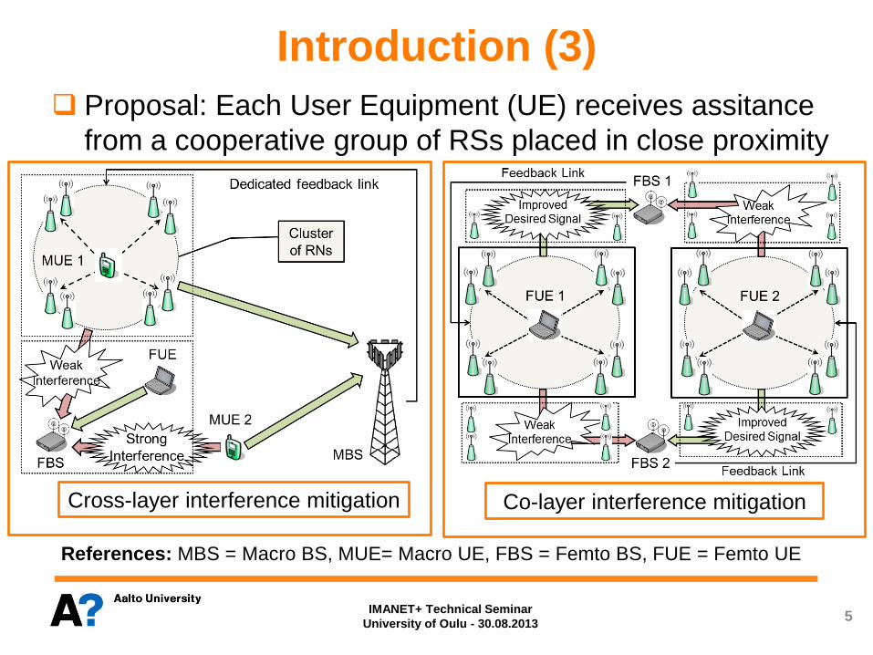
Proposal: Each User Equipment (UE) receives assitance
from a cooperative group of RSs placed in close proximity
References: MBS = Macro BS, MUE= Macro UE, FBS = Femto BS, FUE = Femto UE
IMANET+ Technical Seminar
University of Oulu - 30.08.2013
Introduction (3)
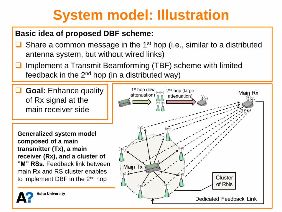
System model: Illustration
6
Goal: Enhance quality
of Rx signal at the
main receiver side
Generalized system model
composed of a main
transmitter (Tx), a main
receiver (Rx), and a cluster of
”M” RSs. Feedback link between
main Rx and RS cluster enables
to implement DBF in the 2nd hop
Basic idea of proposed DBF scheme:
Share a common message in the 1st hop (i.e., similar to a distributed
antenna system, but without wired links)
Implement a Transmit Beamforming (TBF) scheme with limited
feedback in the 2nd hop (in a distributed way)
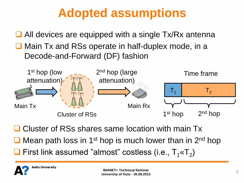
All devices are equipped with a single Tx/Rx antenna
Main Tx and RSs operate in half-duplex mode, in a
Decode-and-Forward (DF) fashion
7
Adopted assumptions
T1
1st hop (low
attenuation)
2nd hop (large
attenuation)
T2
Time frame
1st hop 2nd hop
Main Rx Main Tx
Cluster of RSs
Cluster of RSs shares same location with main Tx
Mean path loss in 1st hop is much lower than in 2nd hop
First link assumed ”almost” costless (i.e., T1«T2)
IMANET+ Technical Seminar
University of Oulu - 30.08.2013
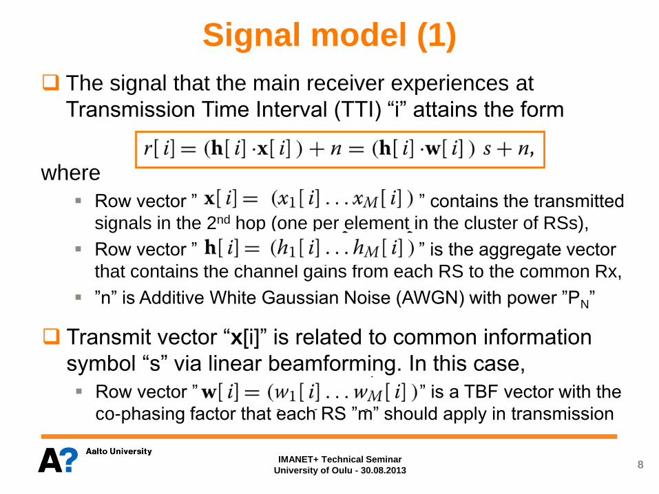
The signal that the main receiver experiences at
Transmission Time Interval (TTI) “i” attains the form
where
Row vector ” ” contains the transmitted
signals in the 2nd hop (one per element in the cluster of RSs),
Row vector ” ” is the aggregate vector
that contains the channel gains from each RS to the common Rx,
”n” is Additive White Gaussian Noise (AWGN) with power ”PN”
8
Signal model (1)
Transmit vector “x[i]” is related to common information
symbol “s” via linear beamforming. In this case,
Row vector ” ” is a TBF vector with the
co-phasing factor that each RS ”m” should apply in transmission
IMANET+ Technical Seminar
University of Oulu - 30.08.2013
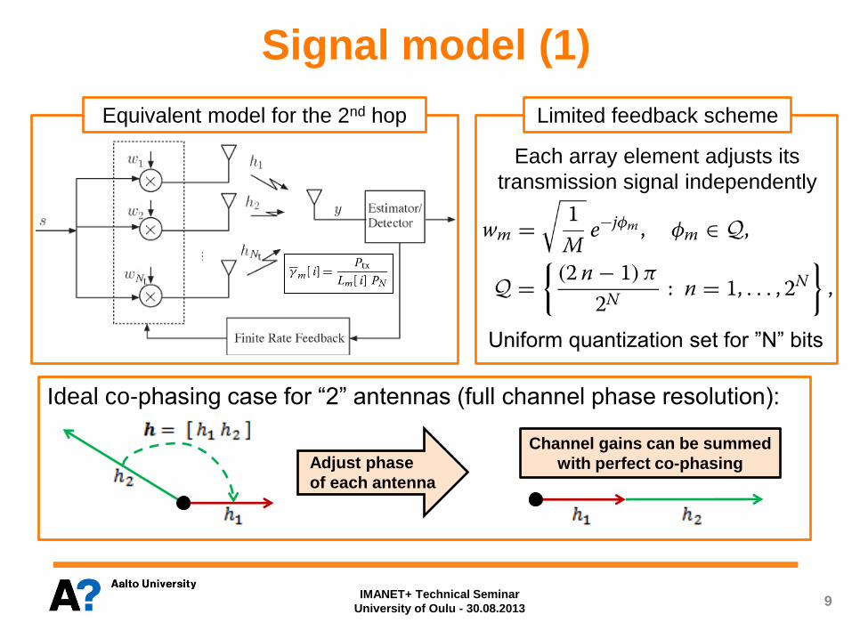
Uniform quantization set for ”N” bits
9
Adjust phase
of each antenna
Ideal co-phasing case for “2” antennas (full channel phase resolution):
Channel gains can be summed
with perfect co-phasing
Equivalent model for the 2nd hop Limited feedback scheme
Each array element adjusts its
transmission signal independently
IMANET+ Technical Seminar
University of Oulu - 30.08.2013
Signal model (1)

Instant.
SNR at
main Rx
Mean received
SNR from mth
array element
Ergodic capacity. Represents the long-term average transmission data
rate. Valid for applications with no strict delay constraints (code words
span over several coherence time intervals of a fading channel)
Outage probability. Represents the probability that an outage occurs in
an specified TTI because target rate cannot be supported with actual
channel state. Appropriate for contant-rate delay-limited transmissions
Bit error probability (BEP). Probability of making a wrong estimation of
the information bit that is being transmitted
10
Performance analysis (1)
To compute the previous performance measures, we need to
determine a suitable expression for the Probability Density Function
(PDF) of the instantaneous received SNR at the main receiver
”Lm[i]” is the total path loss attenuation for the mth signal path
Performance measures
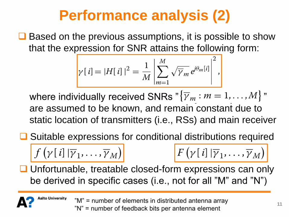
Based on the previous assumptions, it is possible to show
that the expression for SNR attains the following form:
where individually received SNRs ” ”
are assumed to be known, and remain constant due to
static location of transmitters (i.e., RSs) and main receiver
11
Performance analysis (2)
Suitable expressions for conditional distributions required
Unfortunable, treatable closed-form expressions can only
be derived in specific cases (i.e., not for all ”M” and ”N”)
”M” = number of elements in distributed antenna array
”N” = number of feedback bits per antenna element
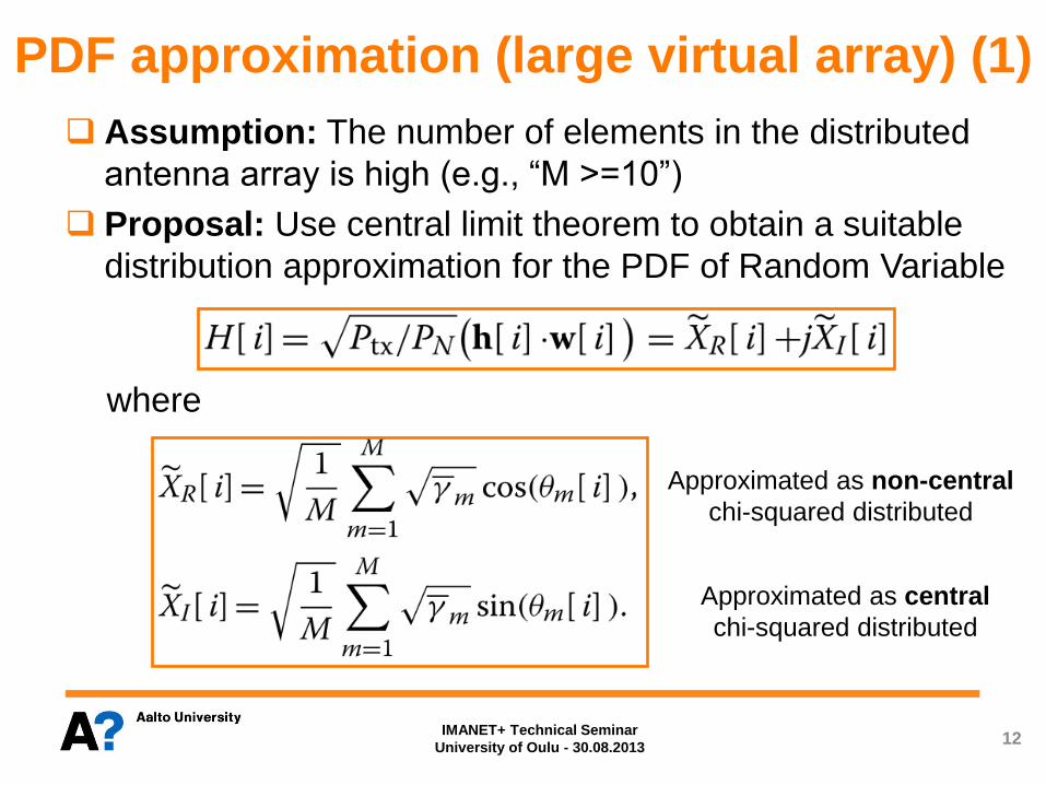
Approximated as non-central
chi-squared distributed
Assumption: The number of elements in the distributed
antenna array is high (e.g., “M >=10”)
Proposal: Use central limit theorem to obtain a suitable
distribution approximation for the PDF of Random Variable
where
12
PDF approximation (large virtual array) (1)
Approximated as central
chi-squared distributed
IMANET+ Technical Seminar
University of Oulu - 30.08.2013
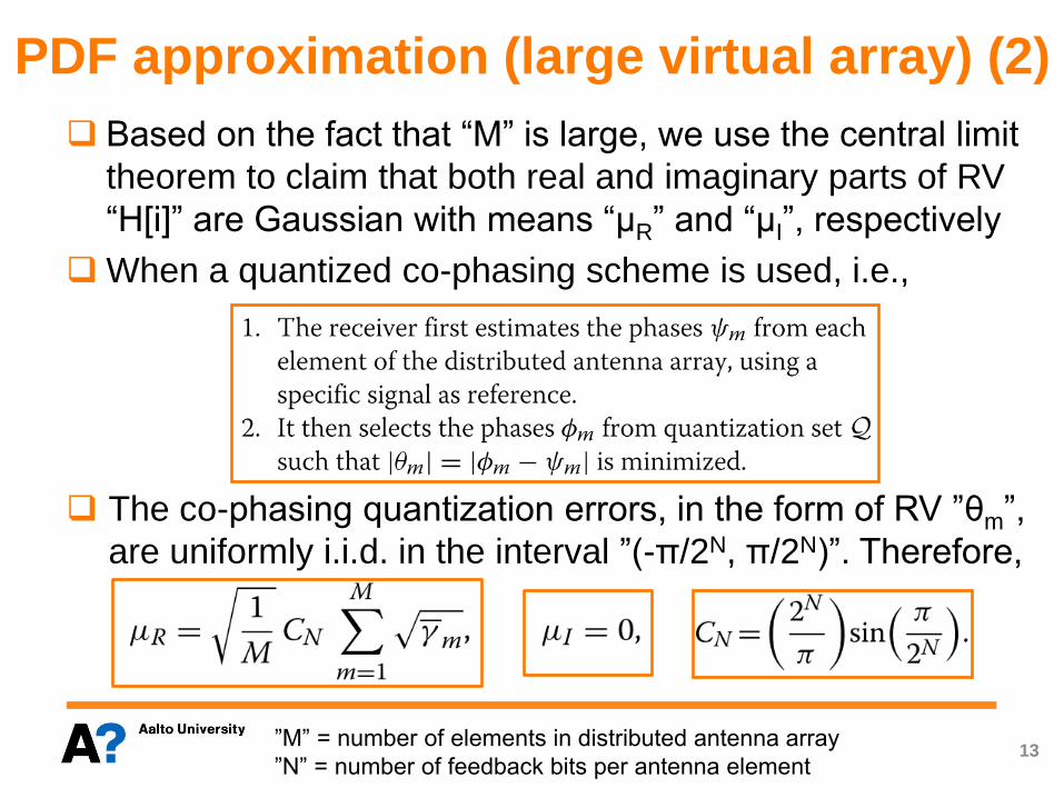
Based on the fact that “M” is large, we use the central limit
theorem to claim that both real and imaginary parts of RV
“H[i]” are Gaussian with means “μR” and “μI”, respectively
When a quantized co-phasing scheme is used, i.e.,
The co-phasing quantization errors, in the form of RV ”θm”,
are uniformly i.i.d. in the interval ”(-π/2N, π/2N)”. Therefore,
13
PDF approximation (large virtual array) (2)
”M” = number of elements in distributed antenna array
”N” = number of feedback bits per antenna element

Main result: The PDF for the received SNR of the DBF
scheme, i.e., “Z = |XR|2+ |XI|2”, can be expressed as a
weighted sum of non-central chi-squared PDFs
where
are the standard deviations of the real and imaginary
parts of RV ”H[i]”, and
is the corresponding weighting factor
14
PDF approximation (large virtual array) (3)
IMANET+ Technical Seminar
University of Oulu - 30.08.2013
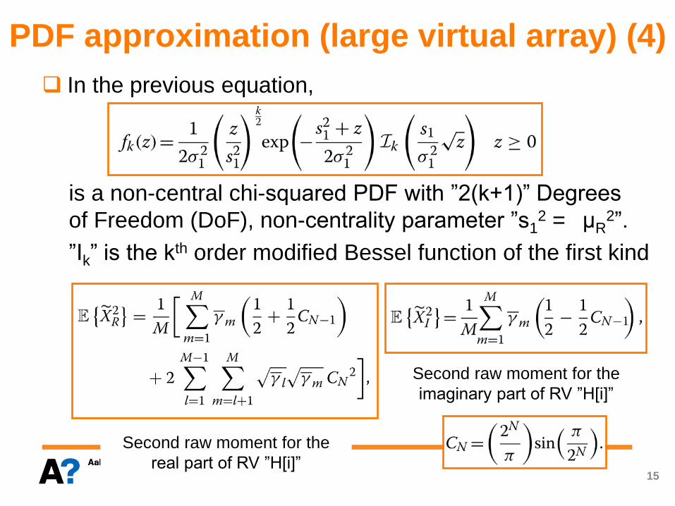
In the previous equation,
is a non-central chi-squared PDF with ”2(k+1)” Degrees
of Freedom (DoF), non-centrality parameter ”s12 = μR
2”.
”Ik” is the kth order modified Bessel function of the first kind
15
PDF approximation (large virtual array) (4)
Second raw moment for the
real part of RV ”H[i]”
Second raw moment for the
imaginary part of RV ”H[i]”
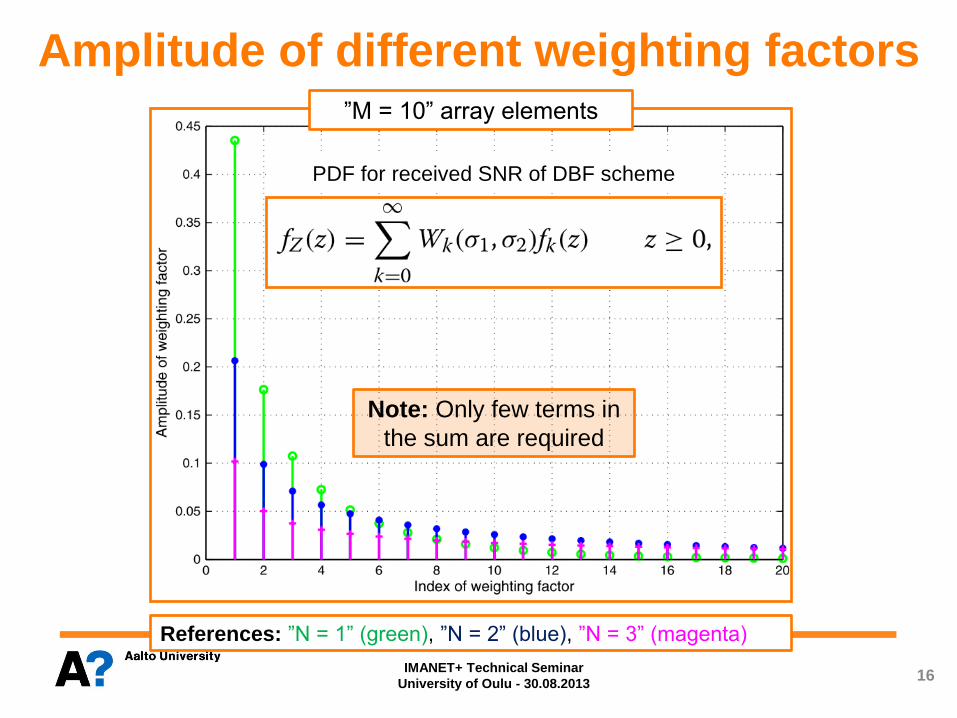
Amplitude of different weighting factors
PDF for received SNR of DBF scheme
References: ”N = 1” (green), ”N = 2” (blue), ”N = 3” (magenta)
”M = 10” array elements
16 IMANET+ Technical Seminar
University of Oulu - 30.08.2013
Note: Only few terms in
the sum are required

Outage probability (1)
17
To evaluate the performance of a mobile communications
system, it is usually assumed that transmission is
successful if
where ”γ0” is selected to guarantee a certain QoS, i.e.,
The closed-form formula for the received SNR
Cumulative Distribution Function (CDF) is required, and
can be obtained from the previously derived PDF formula
approximation.
”QM(a,b)” is the generalized Marcum Q-function of order ”M”
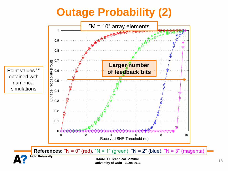
Outage Probability (2)
PDF for received SNR of DBF scheme
References: ”N = 0” (red), ”N = 1” (green), ”N = 2” (blue), ”N = 3” (magenta)
18 IMANET+ Technical Seminar
University of Oulu - 30.08.2013
”M = 10” array elements
Larger number
of feedback bits Point values ’*’
obtained with
numerical
simulations

Outage Probability (3)
Power
imbalance
situation
19 IMANET+ Technical Seminar
University of Oulu - 30.08.2013
”M = 10” array elements
Array
elements
grouped in
two cluster
References: ”N = 0” (red), ”N = 1” (green), ”N = 2” (blue), ”N = 3” (magenta). Solid lines:
Perfect channel power balance (”δ = 0 dB”). Dashed lines: Medium channel power
imbalance (”δ = 3 dB”). Dashed-dotted lines: large channel power imbalance (”δ = 6 dB”).
Larger number
of feedback bits
Point values ’*’
obtained with
numerical
simulations
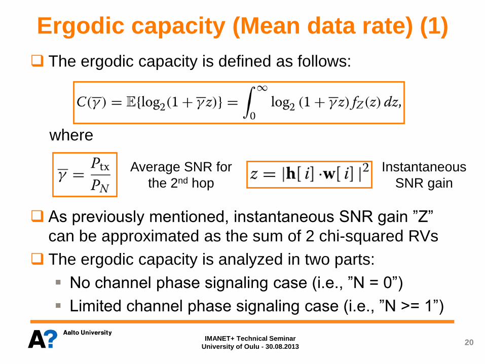
Ergodic capacity (Mean data rate) (1)
20
The ergodic capacity is defined as follows:
where
As previously mentioned, instantaneous SNR gain ”Z”
can be approximated as the sum of 2 chi-squared RVs
The ergodic capacity is analyzed in two parts:
No channel phase signaling case (i.e., ”N = 0”)
Limited channel phase signaling case (i.e., ”N >= 1”)
Average SNR for
the 2nd hop
Instantaneous
SNR gain
IMANET+ Technical Seminar
University of Oulu - 30.08.2013
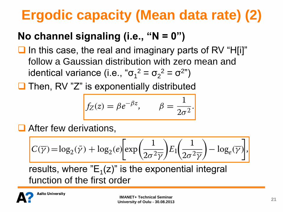
Ergodic capacity (Mean data rate) (2)
21
No channel signaling (i.e., “N = 0”)
In this case, the real and imaginary parts of RV “H[i]”
follow a Gaussian distribution with zero mean and
identical variance (i.e., “σ12 = σ2
2 = σ2”)
Then, RV ”Z” is exponentially distributed
After few derivations,
results, where ”E1(z)” is the exponential integral
function of the first order
IMANET+ Technical Seminar
University of Oulu - 30.08.2013

Ergodic capacity (Mean data rate) (3)
22
Limited channel phase signaling (i.e., “N >=1”)
In this situation, aim is to calculate
where ”Wk(σ1, σ2)” is the weighting factor and ”fk(z)” is a
non-central chi-squared PDF
At this point of the analysis, Jensen’s inequality
is used (valid when ”g(x)” is a concave function)
Jensen’s inequality becomes particularly accurate when
the values of RV ”Z” become concentrated near the mean
IMANET+ Technical Seminar
University of Oulu - 30.08.2013

Ergodic capacity (Mean data rate) (4)
23
Limited channel phase signaling (cont'd)
The fading figure is used to analyze the degree of
variability of RV ”Z”
Finally, the following closed-form approximation is derived
Note: This approximation provides an strict upper bound for the ergodic capacity
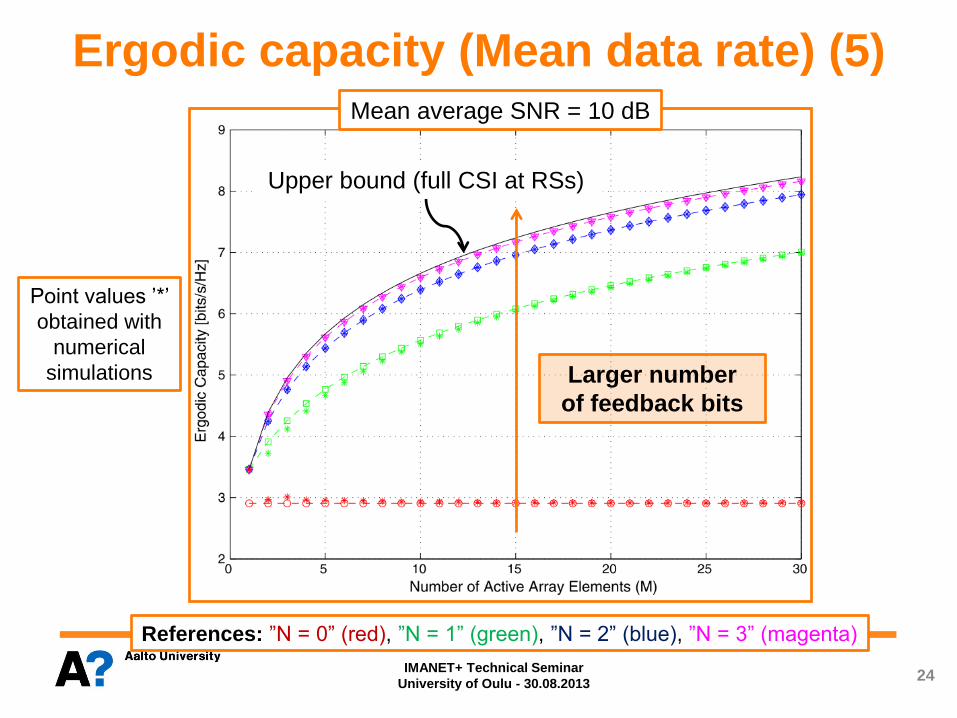
Ergodic capacity (Mean data rate) (5)
References: ”N = 0” (red), ”N = 1” (green), ”N = 2” (blue), ”N = 3” (magenta)
24 IMANET+ Technical Seminar
University of Oulu - 30.08.2013
Mean average SNR = 10 dB
Upper bound (full CSI at RSs)
Larger number
of feedback bits
Point values ’*’
obtained with
numerical
simulations

Ergodic capacity (Mean data rate) (6)
References: ”M = 10” (green), ”M = 20” (blue), ”M = 30” (magenta)
25 IMANET+ Technical Seminar
University of Oulu - 30.08.2013
Mean average SNR = 10 dB
Larger number
of array elements
(cooperative nodes)
Point values ’*’
obtained with
numerical
simulations
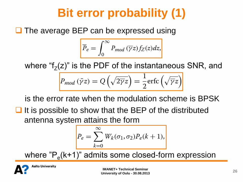
Bit error probability (1)
26
The average BEP can be expressed using
where “fZ(z)” is the PDF of the instantaneous SNR, and
is the error rate when the modulation scheme is BPSK
It is possible to show that the BEP of the distributed
antenna system attains the form
where ”Pe(k+1)” admits some closed-form expression
IMANET+ Technical Seminar
University of Oulu - 30.08.2013

Ratio between energy
deterministic and
random components
Bit error probability (2) BEP for a non-central chi-squared distributed RV with ”n” degrees of freedom
Multichannel
order
Confluent
hypergeometric
funtion
Pochhammer’s
symbol
BEP formula when ”M = 1”
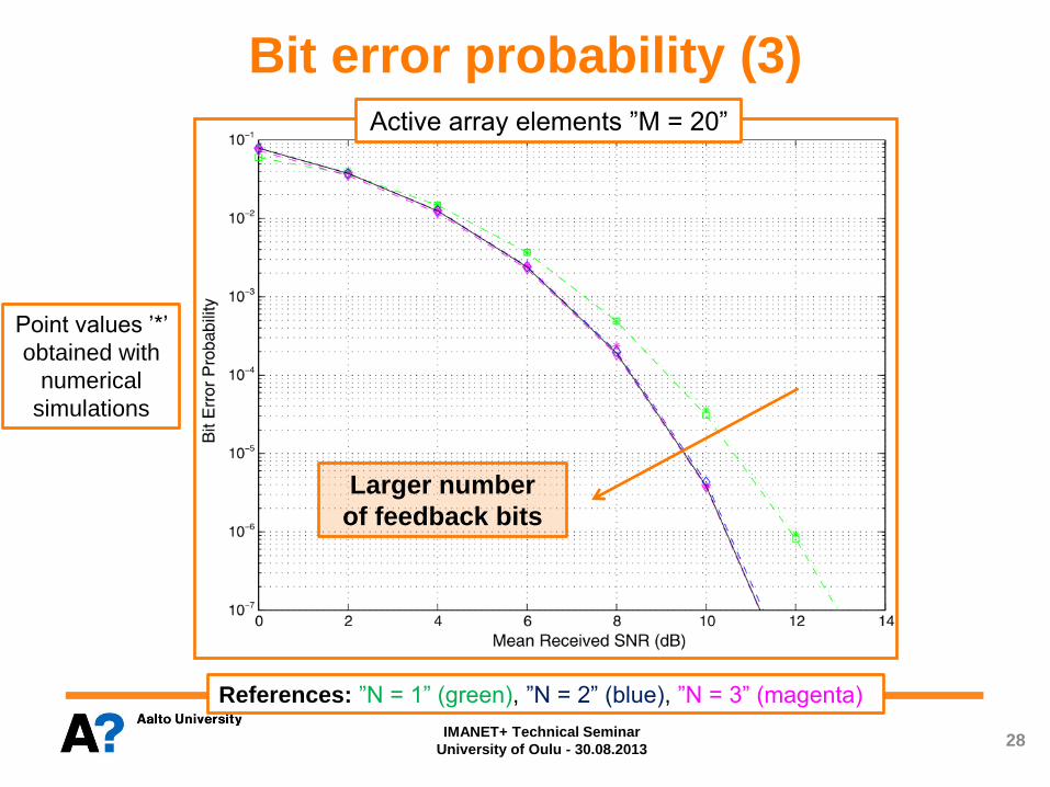
Bit error probability (3)
References: ”N = 1” (green), ”N = 2” (blue), ”N = 3” (magenta)
28 IMANET+ Technical Seminar
University of Oulu - 30.08.2013
Active array elements ”M = 20”
Larger number
of feedback bits
Point values ’*’
obtained with
numerical
simulations
29
Summary of results The performance of a DBF scheme was studied in case of
different channel phase feedback resolutions
Study was done in the context of a massive DBF architecture,
composed by a main Tx, a main Rx, and a cluster of RSs
■ First hop is considered practically costless
■ Bottleneck of the cooperative architecture assumed in 2nd hop
Closed-form approximations for three different performance
measures were derived (PDF/CDF approximations for Rx SNR)
■ Outage probability (Outage capacity)
■ Ergodic capacity (Mean data rate)
■ Bit error probability
It was observed that the achievable end-to-end performance,
when using small amounts of channel phase information (per
RS) is close to the full channel phase information upper bound
IMANET+ Technical Seminar University
of Oulu - 30.08.2013
Performance of Distributed
Beamforming for Dense Cooperative
Networks with Limited Feedback
Questions and/or Comments?
IMANET+ Technical Seminar Program
30th August, 2013 · University of Oulu, Oulu
30