performance of magnetic-superconductor non …shura.shu.ac.uk/14359/1/carbone performance of...
TRANSCRIPT

Performance of Magnetic-Superconductor Non-Contact Harmonic Drive for Cryogenic Space Applications
PEREZ-DIAZ, Jose, DIEZ-JIMENEZ, Efren, VALIENTE-BLANCO, Ignacio, CRISTACHE, Cristian, ALVAREZ-VALENZUELA, Marco-Antonio, SANCHEZ-GARCIA-CASARRUBIOS, Juan, FERDEGHINI, Carlo, CANEPA, Fabio, HORNIG, Wolfgang, CARBONE, Giuseppe <http://orcid.org/0000-0003-0831-8358>, PLECHACEK, Jan, AMORIM, António, FREDERICO, Tiago, GORDO, Paulo, ABREU, Jorge, SANZ, Violeta, RUIZ-NAVAS, Elisa-Maria and MARTINEZ-ROJAS, Juan-Antonio
Available from Sheffield Hallam University Research Archive (SHURA) at:
http://shura.shu.ac.uk/14359/
This document is the author deposited version. You are advised to consult the publisher's version if you wish to cite from it.
Published version
PEREZ-DIAZ, Jose, DIEZ-JIMENEZ, Efren, VALIENTE-BLANCO, Ignacio, CRISTACHE, Cristian, ALVAREZ-VALENZUELA, Marco-Antonio, SANCHEZ-GARCIA-CASARRUBIOS, Juan, FERDEGHINI, Carlo, CANEPA, Fabio, HORNIG, Wolfgang, CARBONE, Giuseppe, PLECHACEK, Jan, AMORIM, António, FREDERICO, Tiago, GORDO, Paulo, ABREU, Jorge, SANZ, Violeta, RUIZ-NAVAS, Elisa-Maria and MARTINEZ-ROJAS, Juan-Antonio (2015). Performance of Magnetic-Superconductor Non-Contact Harmonic Drive for Cryogenic Space Applications. Machines, 3 (3), 138-156.
Copyright and re-use policy
See http://shura.shu.ac.uk/information.html
Sheffield Hallam University Research Archivehttp://shura.shu.ac.uk

Machines 2015, 3, 138-156; doi:10.3390/machines3030138
machines ISSN 2075-1702
www.mdpi.com/journal/machines/
Article
Performance of Magnetic-Superconductor Non-Contact Harmonic Drive for Cryogenic Space Applications
Jose Luis Perez-Diaz 1, Efren Diez-Jimenez 2,*, Ignacio Valiente-Blanco 3, Cristian Cristache 1, Marco-Antonio Alvarez-Valenzuela 2, Juan Sanchez-Garcia-Casarrubios 3, Carlo Ferdeghini 4, Fabio Canepa 4, Wolfgang Hornig 5, Giuseppe Carbone 6, Jan Plechacek 7, António Amorim 8, Tiago Frederico 8, Paulo Gordo 8, Jorge Abreu 8, Violeta Sanz 9, Elisa-Maria Ruiz-Navas 10 and Juan-Antonio Martinez-Rojas1
1 Departamento de Teoría de la Señal y Comunicaciones, Universidad de Alcalá, 28871 Alcalá de
Henares, Spain; E-Mails: [email protected] (J.L.P.D.); [email protected] (C.C.);
[email protected] (M.-R.J.A.) 2 Departamento de Ingeniería Mecánica, Universidad Carlos III de Madrid, 28911 Leganés, Spain;
E-Mail: [email protected] 3 R&D department, MAG SOAR SL, 28341, Valdemoro, Spain;
E-Mails: [email protected] (I.V.-B.); [email protected] (J.S.-G.-C.) 4 CNR-SPIN institute, Genova 16151, Italy; E-Mails: [email protected] (C.F.);
[email protected] (F.C.) 5 BPE e.K., 90542 Eckental, Germany; E-Mail: [email protected] 6 LARM group, Università di Cassino e del Lazio Meridionale 03043 Cassino, Italy;
E-Mail: [email protected] 7 CAN superconductors, 251 68 Kamenice, Czech Republic;
E-Mail: [email protected] 8 SIM group, Faculdade de ciencias da Universidade de Lisboa, 1749-016 Lisbon, Portugal;
E-Mails: [email protected] (A.A.); [email protected] (T.F.); [email protected] (P.G.);
[email protected] (J.A.) 9 Rolls-Royce Dahlewitz, Berlin 10117, Germany; E-Mail: [email protected] 10 Departamento de ingeniería de materiales, Universidad Carlos III de Madrid, 28911, Leganés,
Spain; E-Mail: [email protected]
* Author to whom correspondence should be addressed; E-Mail: [email protected];
Tel.: +34-91-624-99-12.
Academic Editor: David Mba
OPEN ACCESS
Machines 2015, 3 139
Received: 30 May 2015 / Accepted: 23 June 2015 / Published: 1 July 2015
Abstract: Harmonic drives are profusely used in aerospace mainly because of their
compactness and large reduction ratio. However, their use in cryogenic environments is
still a challenge. Lubrication and fatigue are non-trivial issues under these conditions. The
objective of the Magnetic-Superconductor Cryogenic Non-contact Harmonic Drive
(MAGDRIVE) project, funded by the EU Space FP7, is to design, build, and test a new
concept of MAGDRIVE. Non-contact interactions among magnets, soft magnetic
materials, and superconductors are efficiently used to provide a high reduction ratio gear
that smoothly and naturally operates at cryogenic environments. The limiting elements of
conventional harmonic drives (teeth, flexspline, and ball bearings) are substituted by
contactless mechanical components (magnetic gear and superconducting magnetic
bearings). The absence of contact between moving parts prevents wear, lubricants are no
longer required, and the operational lifetime is greatly increased. This is the first
mechanical reducer in mechanical engineering history without any contact between moving
parts. In this paper, the test results of a −1:20 inverse reduction ratio MAGDRIVE
prototype are reported. In these tests, successful operation at 40 K and 10−3 Pa was
demonstrated for more than 1.5 million input cycles. A maximum torque of 3 N·m and an
efficiency of 80% were demonstrated. The maximum tested input speed was 3000 rpm, six
times the previous existing record for harmonic drives at cryogenic temperatures.
Keywords: Magdrive; Harmonic drive; Magnetic gear; Cryogenics; Space mechanism;
Contactless device; Superconducting magnetic bearings
1. Introduction
Harmonic drives (HD) are power transmission mechanisms able to develop high ratios, providing a
high positional precision, with a relatively low weight/volume ratio, high torque capability, and
near-zero backlash. Invented by Musser in 1955 [1] for aerospace applications, HD are currently
widely used in robotics, medical equipment, printing presses, vehicles, and defense. They are used in
Space mainly because of a good performance in terms of reduction ratio and good efficiency with
respect to conventional gear trains [2,3]. Typically, the temperature operation range of HD in space is
limited from −40 °C to +100 °C [4,5].
The space and aerospace industries are increasingly demanding mechanisms able to work in
cryogenic environments (T < 100 K) [6]. As signal-to-noise ratios in sensors increase as temperature
decreases, cryogenic environments are very desirable for accurate and precise measurements such as
those required by far infrared interferometer spectroscopy [7,8]. Solar array drive mechanisms or large
antenna deployment and pointing mechanisms in which HD are traditionally used require increasingly
demanding operational conditions [9].
Machines 2015, 3 140
At very low temperatures, conventional mechanisms present severe tribological problems in
bearings and teeth like cold spots, fatigue, and wear [10,11]. Only solid lubricants such as Telfon
(PFTE) or Molybdenum disulfide (MoS2) can be a solution at low temperatures [12,13]. However, for
long life-time operation, solid lubricants turn out not to be a very reliable solution and the decrease of
the efficiency in the mechanism is very significant.
Specifically, the application of HD mechanisms is limited by the severe drop of the efficiency at
very low temperatures (T < 100 K). For instance, the efficiency of conventional HD falls below 20% at
temperatures below −40 °C, even when using dry lubricants like the MAPLUB SH050a Grease [14].
Additionally, dry lubricants present grating, clutching, rapid wear out, instability of the friction
coefficient, formation of cold weld centers, and losses or decomposition at cryogenic conditions. This
prevents conventional HD with dry lubricants from rotating faster than 500 rpm in the input axle.
Moreover, fatigue associated with the intrinsic flexural functioning of the HD also limits their effective
work life at cryogenic temperatures.
The objective of the Magnetic-Superconductor Cryogenic Non-contact Harmonic Drive
(MAGDRIVE) project, funded by the EU Space FP7, is to design, build, and test a new concept of HD.
Non-contact interactions among magnets, soft magnetic materials, and superconductors are efficiently
used to provide a high reduction ratio gear that smoothly and naturally operates at cryogenic
environments. The limiting elements of conventional HD (teeth, flexspline, and ball bearings) are
substituted by contactless mechanical components (magnetic gear and superconducting magnetic
bearings). The absence of contact between moving parts prevents wear, lubricants are no longer
required, and the operational life time is greatly increased.
In order to achieve a Technology Readiness Level (TRL) 5, a prototype was designed, built, and
tested at a temperature below 60 K and 10−3 Pa. Mechanical performance, including maximum speed,
speed ratio, efficiency, torque, and load capability, was characterized in order to establish the criteria
for the usage of these MAGDRIVE mechanisms for Space.
2. Design and Analysis of the Device
Two contactless technologies were combined and optimized for the first time in a single machine in
order to create the first absolute zero friction drive for transmission of forces and torques. These two
contactless technologies are magnetic gears and Superconducting Magnetic Bearings (SMB).
SMB are axially and radially stable, meanwhile magnetic gears are axially stable but radially
instable. Therefore, a condition for the stability of such a device must be that the mechanical stiffness
of the SMB has to be greater than the “negative stiffness” or instability of the magnetic gears.
2.1. Magnetic Harmonic Drive Gear
Magnetic gears are mechanisms for the conversion of torque/speed. Their teeth do not touch each
other, but instead they are provided with magnets that exert force from a certain distance. Magnetic
gears have several advantages over conventional mechanical gears: lack of wear, silent operation,
reduced vibration, no need of lubrication, reduced maintenance, and improved reliability. Furthermore,
they provide intrinsic overload protection and have no connection between the parts [15–17].

Machines 2015, 3 141
A few years before the HD was invented, Chubb patented an electric motor [18] in which magnetic
teeth and a Nonius or Vernier principle was used. In 1967, Reese [19] patented a coaxial magnetic
gearing arrangement comprising a high-speed axle and a permanent magnetized low-speed rotor with
many magnetic teeth. Despite the fact that the invention could be used as a speed-reducing gear with a
reduction ratio (i) of 50:1, the transmitted torques were small because only one of the parts had
permanent magnetization.
In 2001, Atallah and Howe presented what they called a “high-performance magnetic gearbox” [20].
Rare-earth magnets were used in a topology consisting of two coaxial, low- and high-speed rotors,
with several steel ferromagnetic pole-pieces in between. Using 2D magnetostatic finite element
method simulations, a torque density exceeding 100 kN·m/m3 was calculated for i = 5.5:1. One great
advantage of their system is that it is a single-stage mechanical gearbox with a relatively high torque,
comparable to two- and three-stage helical gearboxes with typical torque densities between
50–150 kNm/m3. In addition, the direction of rotation could be chosen.
In 2003, Rasmussen et al. [21] presented the first experimental results of a simplified coaxial
magnetic gearbox prototype. It produced similar results: i = 5.5:1, with a torque density of around
90 kNm/m3, and an efficiency of 81% (55 W energy power losses at 1000 rpm speed).
Although there is a large background in magnetic gear developments, they have been mostly
optimized in order to obtain a high torque density. Other mechanical aspects of the gear, i.e., gearing
theory, radial instability, vibration damping, backlash, and reduction ratio availability, have not been
taken into account up until now. In the MAGDRIVE prototype described in the present work, the
reduction ratio is i = −20:1. It is the first time such a high ratio is experimentally demonstrated. The
working principle of the MAGDRIVE is like that of the Nonius-Vernier motors as shown in Figure 1.
Figure 1. Scheme of the MAGDRIVE mesh principle.
The elementary mesh unit of a MAGDRIVE is composed of a stator provided with ns permanent
magnet teeth uniformly distributed along a length L, a moving part (output) with no teeth made of soft
magnetic material, and, finally, a single permanent magnet as an input. The condition for this to be an
elementary mesh unit is that |no-ns| = 1, as shown in Figure 1.
Displacement of the input tooth parallel to the length makes the output teeth magnetize and align,
one by one, with the stator teeth. In this way, when the input moves along a length L, the output moves

Machines 2015, 3 142
L/no. Therefore, the reduction of this movement will be i = 1/no provided no is greater than ns. The
ratio will be i = −1/no if no is smaller than ns.
Several elementary reduction units can be repeated N times along a circumference in order to build
a coaxial gear of the same ratio i. In this case, there will be Ns = N∙ns teeth in the stator, No = N∙no teeth in the output, and N = Ns-No teeth in the input member. The reduction ratio for the coaxial gear
can be also calculated as:
O
SO
N
NNi
(1)
This formula is valid for both positive and negative ratios.
Additionally, like in any other kind of mechanism, a kinematic inversion can also be taken
exchanging the roles of “input”, “output”, and “stator” (or mechanical ground). Specifically, the MAGDRIVE prototype was designed comprising two elementary units with
42 teeth in the stator and 40 teeth in the output, obtaining a reduction ratio of i = −1:20 (reversal of the
rotation sense) as it is shown in Figure 2.
Figure 2. Magnetic simulation of MAGDRIVE prototype.
In the MAGDRIVE prototype the external ring was taken as output and the intermediate ring was
taken as the stator. It was designed considering large air gaps between rotatory parts: 1 mm between
output and stator and 2 mm between input and stator. This selection goes against a high torque
capacity but it is a conservative choice for the SMB, which had never been combined before in a single
gear. Input and output axles have to be supported on two pair of SMB, completely passive and contactless.
Rotatory parts of the magnetic gears have instability of the permanent magnet rotors that impose a
stiffness requirement for the bearings that hold the gears. Of course, the weight of each axle must be
Machines 2015, 3 143
supported so an axial load appears. The requirements of radial and axial stiffness had to be deeply
analyzed in this work because they were critical for the design of the SMB, whose stiffness is much
lower than a conventional mechanical ball bearing.
2.2. Superconducting Magnetic Bearings (SMB)
Contactless bearings based in both permanent magnets and superconducting magnetic levitation are
of interest in order to avoid all the tribological problems, such as friction, wear, or energy losses [21–26]
associated with contact at very low temperatures [12]. In addition, there is no contact between the
moving parts, so lubrication is not required. SMB find applications in many fields where lack of contact
is a requirement or an advantage, such as in flywheel systems and transportation [27], cryogenic turbine
flow meters, cryocoolers, and sensitive gyroscopes for space applications, among other applications for
cryogenic and space mechanisms [28–35]. Recently, different shapes, sizes, and combinations of
magnet-superconductors have been explored in order to obtain more stable levitation positions [36–41].
There are some models that are useful to describe this interaction and they can be applied in finite
elements programs, [42–44]. Some other parameters, such as the force relaxation or the rotation losses,
have to be considered from the point of view of the mechanical engineer for an adequate design of the
SMB [45–48].
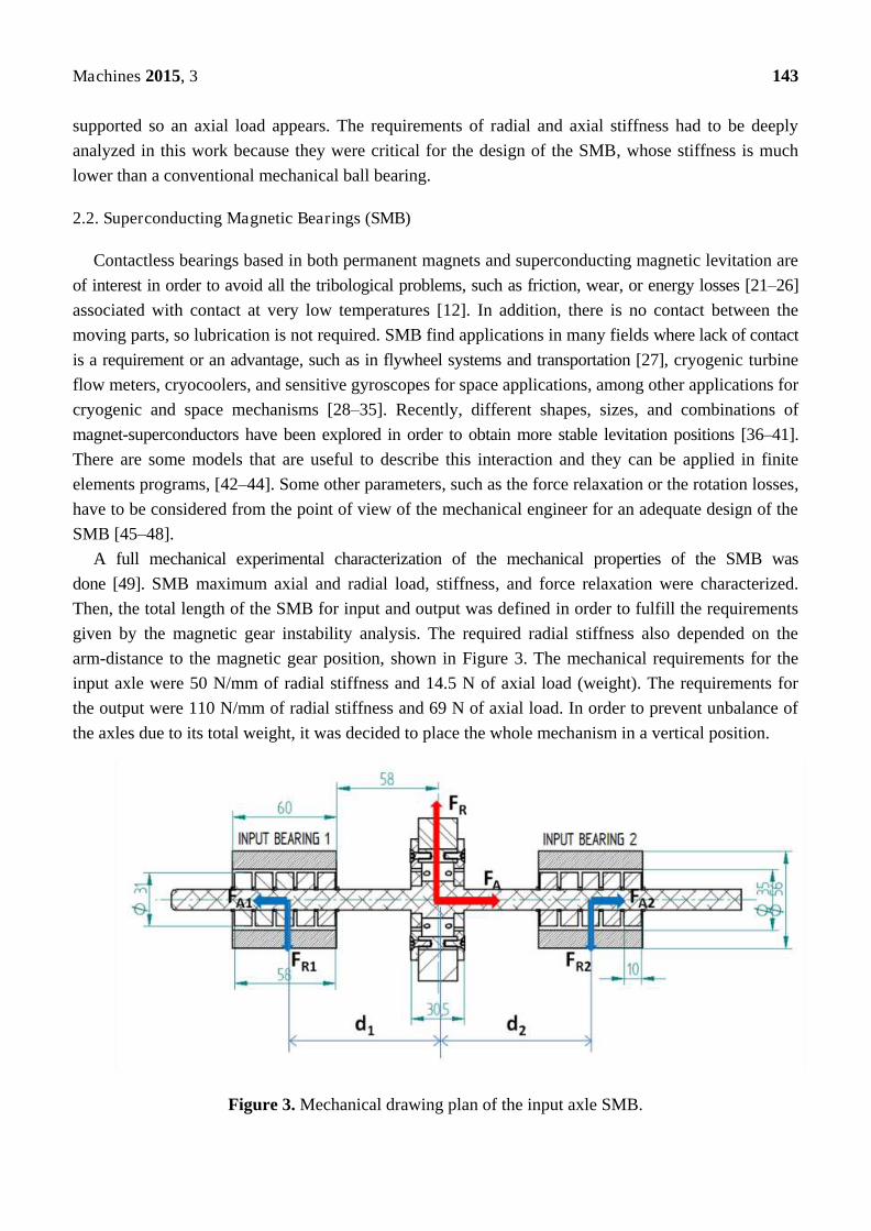
A full mechanical experimental characterization of the mechanical properties of the SMB was
done [49]. SMB maximum axial and radial load, stiffness, and force relaxation were characterized.
Then, the total length of the SMB for input and output was defined in order to fulfill the requirements
given by the magnetic gear instability analysis. The required radial stiffness also depended on the
arm-distance to the magnetic gear position, shown in Figure 3. The mechanical requirements for the
input axle were 50 N/mm of radial stiffness and 14.5 N of axial load (weight). The requirements for
the output were 110 N/mm of radial stiffness and 69 N of axial load. In order to prevent unbalance of
the axles due to its total weight, it was decided to place the whole mechanism in a vertical position.
Figure 3. Mechanical drawing plan of the input axle SMB.

Machines 2015, 3 144
SMB were designed considering YBaCuO as a superconducting material and NdFeB N50 as a
permanent magnet. The air gap between static and rotatory parts was 2 mm for the input axle and
1 mm for the output axle.
A safety factor of 2 was considered in the final design of the SMB. This implies larger SMB
elements (60 mm for input and 120 mm for output). Although MAGDRIVE SMB were oversized for
safety reasons, SMB in general have much lower stiffness and load capacity than a mechanical ball
bearing one. On the other hand, they do not have any friction or wear even at low temperatures, and, as
explained, that was the reason for their selection.
2.3. Mechanical and Thermal Design
Other aspects like thermal management, sensors, and cooling systems were also critical for the
design of the prototype. The prototype operational temperature was aimed to be 60 K. In order to get
such a low temperature, two independent cooling systems were considered: two liquid nitrogen (LN2)
reservoirs and a cryocooler of 48 W at 77 K.
Figure 4. Mechanical model of the prototype including magnetic harmonic drive and SMB.
The critical temperatire of YBaCuO is 90 K. This means that all the superconductors have to be
below 90 K to behave as superconducting material. Therefore, all superconducting bulks were placed
in the static part, directly in conduction to the cryocooler or LN2 reservoirs.
The two floating axles, as shown in Figure 4, were held by a launch-lock system until the system
reached the target temperature. Once the temperature was low enough, the launch-lock would open and
they would be free to float in the vacuum. Similar concepts for launch-lock systems have been used
in several devices [50]. With the axles floating in a high vacuum, the only possible heating source
would be radiation. Since the radiated areas of the floating axles were small, radiation was considered
Machines 2015, 3 145
negligible and, therefore, the temperature of the floating axles in operation was expected to be close to
the one just before release while testing.
2.4. Material Selection
The whole system had to be tested in a vacuum and at minimum 60 K, thus the materials chosen for
each of the parts had to bear these extreme requirements.
For the magnetic gear, SmCo was selected for the permanent magnets and mu-metal for the soft-
magnetic parts. The housings were made of paramagnetic metallic alloys. SmCo magnets do not suffer
spin reorientation transition at low temperatures like NdFeB ones do [51], therefore they are more
stable at 60 K. Mu-metal have been selected because of their low power losses and machinability.
Surrounding materials were selected after doing a trade-off between high thermal conduction, low
electrical conduction, low magnetic permeability, similar thermal contractions, and adequate
outgassing rates. The parts were done in aluminum 7075, stainless steel 304, and titanium alloys.
3. Prototype Manufacturing and Assembly
It is essential for the correct operation of the gear that all the magnetic parts are aligned and uniform
in respect to each other. The geometrical tolerances for the magnet dimensions were measured from
+0.0 to +0.1 mm for each direction. Thus, the positioning of the magnets had to be done with the same
or better precision (±0.05 mm precision in the positioning inside their housings).
SmCo magnets do not have any coating by default, so it was necessary to apply a coating (in this
case, Stycast Epoxy) in order to prevent any magnetic chips coming from the magnet.
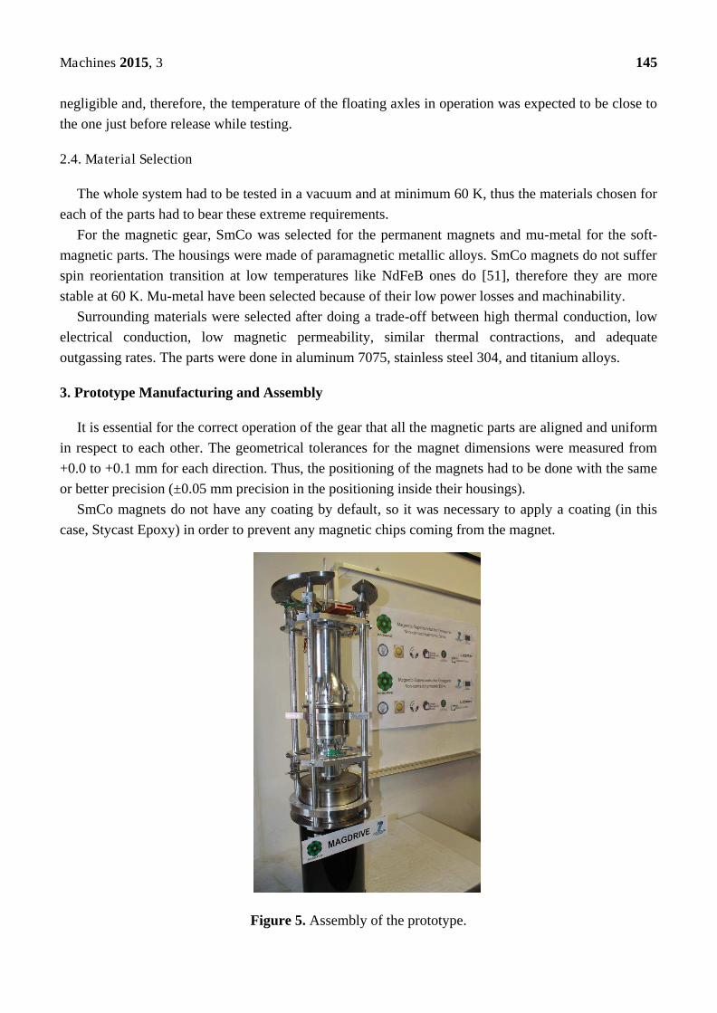
Figure 5. Assembly of the prototype.

Machines 2015, 3 146
The parts were assembled in a vertical configuration. Four aluminum columns were attached to the
bottom LN2 deposit. This deposit was established as the reference plane; from there, all the different
elements were guided through the aluminum columns and placed into the right height, as shown in
Figure 5. Some special tools were manufactured for inserting each subassembly in the right position.
The assembly sequence was followed according to the designed procedure. Finally, the prototype was integrated in the thermal-vacuum chamber, shown in Figure 6. It was
connected to an upper LN2 tank acting as a second cold plate and the cryocooler finger was also
connected to the static part of the prototype. The LN2 thermal circuit was used to cool down all the
surrounding and external radiation foil and the cryocooler was used to cool down the superconducting
bulks directly. Both systems were not connected between themselves.
Figure 6. Prototype integrated in the thermal-vacuum chamber.
4. Experimental Test Rig
The experimental test rig for the prototype was composed of a thermal-vacuum chamber, including
all the vacuum and cooling sub-systems and a sensing system that has different kinds of sensors for
measuring the different mechanical parameters.
4.1. Thermal-Vacuum Chamber
The thermal-vacuum chamber and all the cooling and vacuum systems were adjusted and prepared
for the operational test, shown in Figure 7. The chamber is a 304 stainless steel cylinder with a 1 m
height and a 650 mm diameter, having a top and bottom flange with four lateral optical windows. The
vacuum system is composed of a turbomolecular pump able to reduce the inner pressure below
10−3 Pa. The cooling system is composed of two LN2 tanks fed by a LN2 dewar with a 100 L capacity,

Machines 2015, 3 147
and a cryocooler DE-104 from ARS Company with a 48 W cooling capacity at 77 K of the cold finger,
able to reach 20 K. The chamber is provided with two endoscopic webcams to record video and picture
inside the chamber.
Figure 7. Thermal-vacuum chamber and external test rig elements.
The mechanical power was provided by an AC motor and a brake, installed in the top and bottom
flange. Magnetomechanical feed-throughs were used for trespassing the mechanical power through the
chamber flanges to the MAGDRIVE prototype.
4.2. Sensing System
The whole sensing system was composed of different kinds of sensors as shown in Figure 8. The
sensors installed were: input and output torque and speed sensors (outside the vacuum chamber), input
and output rotation and position contactless sensors, six inner temperature sensors in the stator part,
and four magnetic field sensors all along the height in order to characterize thermal and magnetic
behavior. In addition to those main sensors, some secondary sensors were added for the temperature
control system: three temperature sensors and two level detectors for the LN2 deposits.
The output and input torque/speed sensors were two DATAFLEX 16-10 from KTR Company. The
temperature sensors were PT-111 model from Lakeshore. The temperature control system sensors were
composed of PTC sensors and a proportional-integral-derivative (PID) controller. The magnetic field
sensors were HGCA-3020 model from Lakeshore. All the sensors were monitored by a PXI model
system from National Instruments.

Machines 2015, 3 148
A contactless position and rotation sensor based on Hall Effect probes had to be specifically
designed for measuring position and rotation of the two floating axles, shown in Figure 9. Two
position and rotation sensors were needed for the input and output axle, respectively. In order to
keep the Hall probes in the right temperature operation range, the sensors had a heater and a PID
external controller.
Figure 8. Sensors of the test rig scheme.
Figure 9. Rotation and position contactless sensor for the floating axles.
These new sensors monitored the X, Y and Z position and rotation of both axles in order to measure
run-outs and tilting of the floating axles. The precision of the sensors was ± 1 µm in linear direction
and ± 1 arcmin in rotation.
Machines 2015, 3 149
5. Performance Test Results and Discussion
The test campaign results are presented in this section.
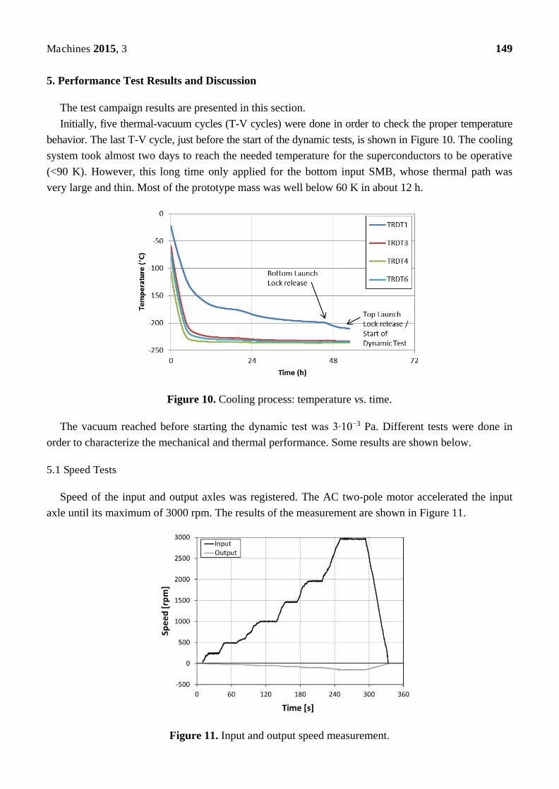
Initially, five thermal-vacuum cycles (T-V cycles) were done in order to check the proper temperature
behavior. The last T-V cycle, just before the start of the dynamic tests, is shown in Figure 10. The cooling
system took almost two days to reach the needed temperature for the superconductors to be operative
(<90 K). However, this long time only applied for the bottom input SMB, whose thermal path was
very large and thin. Most of the prototype mass was well below 60 K in about 12 h.
Figure 10. Cooling process: temperature vs. time.
The vacuum reached before starting the dynamic test was 3∙10−3 Pa. Different tests were done in
order to characterize the mechanical and thermal performance. Some results are shown below.
5.1 Speed Tests
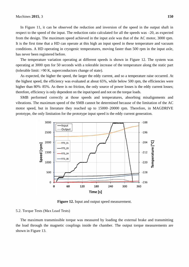
Speed of the input and output axles was registered. The AC two-pole motor accelerated the input
axle until its maximum of 3000 rpm. The results of the measurement are shown in Figure 11.
Figure 11. Input and output speed measurement.
Machines 2015, 3 150
In Figure 11, it can be observed the reduction and inversion of the speed in the output shaft in
respect to the speed of the input. The reduction ratio calculated for all the speeds was –20, as expected
from the design. The maximum speed achieved in the input axle was that of the AC motor, 3000 rpm.
It is the first time that a HD can operate at this high an input speed in these temperature and vacuum
conditions. A HD operating in cryogenic temperatures, moving faster than 500 rpm in the input axle,
has never been registered before.
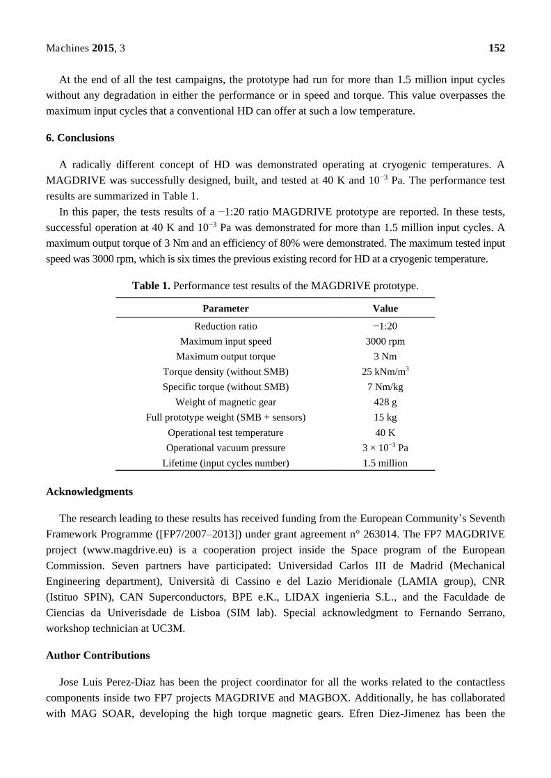
The temperature variation operating at different speeds is shown in Figure 12. The system was
operating at 3000 rpm for 50 seconds with a tolerable increase of the temperature along the static part
(tolerable limit: >90 K, superconductors change of state).
As expected, the higher the speed, the larger the eddy current, and so a temperature raise occurred. At
the highest speed, the efficiency was evaluated at about 65%, while below 500 rpm, the efficiencies were
higher than 80%–85%. As there is no friction, the only source of power losses is the eddy current losses;
therefore, efficiency is only dependent on the input/speed and not on the torque loads.
SMB performed correctly at those speeds and temperatures, absorbing misalignments and
vibrations. The maximum speed of the SMB cannot be determined because of the limitation of the AC
motor speed, but in literature they reached up to 15000–20000 rpm. Therefore, in MAGDRIVE
prototype, the only limitation for the prototype input speed is the eddy current generation.
Figure 12. Input and output speed measurement.
5.2. Torque Tests (Max Load Tests)
The maximum transmissible torque was measured by loading the external brake and transmitting
the load through the magnetic couplings inside the chamber. The output torque measurements are
shown in Figure 13.

Machines 2015, 3 151
Figure 13. Output torque measurement.
The maximum transmissible torque was rated in 3 Nm, which gives a torque density of around
25 kNm/m3. Although the torque and corresponding torque density are low for practical applications,
they correspond properly with the Finite Element Method (FEM) model results validating them.
Torque capability can be easily improved by reducing air gaps (too conservative), using NdFeB
magnets (caring about the spin reorientation transition), and optimizing shapes and sizes of the teeth.
In fact, recent designs have shown torque densities close to 100 kNm/m3, in the same order of
magnitude as conventional HD.
5.3. Lifetime
Several long-duration tests were done at 50, 250 and 500 rpm. In Figure 14, one long-duration test
at 250 rpm operating for almost one hour continuously is shown.
Figure 14. Long-duration operation test.
Machines 2015, 3 152
At the end of all the test campaigns, the prototype had run for more than 1.5 million input cycles
without any degradation in either the performance or in speed and torque. This value overpasses the
maximum input cycles that a conventional HD can offer at such a low temperature.
6. Conclusions
A radically different concept of HD was demonstrated operating at cryogenic temperatures. A
MAGDRIVE was successfully designed, built, and tested at 40 K and 10−3 Pa. The performance test
results are summarized in Table 1.
In this paper, the tests results of a −1:20 ratio MAGDRIVE prototype are reported. In these tests,
successful operation at 40 K and 10−3 Pa was demonstrated for more than 1.5 million input cycles. A
maximum output torque of 3 Nm and an efficiency of 80% were demonstrated. The maximum tested input
speed was 3000 rpm, which is six times the previous existing record for HD at a cryogenic temperature.
Table 1. Performance test results of the MAGDRIVE prototype.
Parameter Value
Reduction ratio −1:20
Maximum input speed 3000 rpm
Maximum output torque 3 Nm
Torque density (without SMB) 25 kNm/m3
Specific torque (without SMB) 7 Nm/kg
Weight of magnetic gear 428 g
Full prototype weight (SMB + sensors) 15 kg
Operational test temperature 40 K
Operational vacuum pressure 3 × 10⁻³ Pa
Lifetime (input cycles number) 1.5 million
Acknowledgments
The research leading to these results has received funding from the European Community’s Seventh
Framework Programme ([FP7/2007–2013]) under grant agreement n° 263014. The FP7 MAGDRIVE
project (www.magdrive.eu) is a cooperation project inside the Space program of the European
Commission. Seven partners have participated: Universidad Carlos III de Madrid (Mechanical
Engineering department), Università di Cassino e del Lazio Meridionale (LAMIA group), CNR
(Istituo SPIN), CAN Superconductors, BPE e.K., LIDAX ingenieria S.L., and the Faculdade de
Ciencias da Univerisdade de Lisboa (SIM lab). Special acknowledgment to Fernando Serrano,
workshop technician at UC3M.
Author Contributions
Jose Luis Perez-Diaz has been the project coordinator for all the works related to the contactless
components inside two FP7 projects MAGDRIVE and MAGBOX. Additionally, he has collaborated
with MAG SOAR, developing the high torque magnetic gears. Efren Diez-Jimenez has been the

Machines 2015, 3 153
technical work coordinator for all the developments. Ignacio Valiente-Blanco has been responsible for
the SMB developments and the high torque density MAGDRIVE optimization, Cristian Cristache was
responsible for the mechanical and thermal design and he has also performed most of the tests,
Marco-Antonio Alvarez-Valenzuela has been responsible for the manufacturing of the prototypes, and
Juan Sanchez-Garcia-Casarrubios has been in charge of all the electronic and auxiliary systems needed
for testing the prototypes. Carlo Ferdeghini and Fabio Canepa have determined the magnetic properties
of materials at cryogenic temperatures. Wolfgang Hornig has machined the most delicate parts of the
prototype. Giuseppe Carbone has built the whole sensing system. Jan Plechacek has provided the
superconducting bulks in the correct sizes and shapes. Antonio Amorim, Tiago Frederico,
Paulo Gordo and Jorge Abreu have been responsible for the testing. Violeta Sanz has oriented the
development towards the space industry applicability. Fernando Serrano, workshop technician at
UC3M, has been responsible for the manufacturing of several main parts. Elisa Ruiz Navas and
Juan Antonio Martínez Rojas have provided scientific advice related to materials and sensors.
Conflicts of Interest
The authors declare no conflict of interest.
References
1. Musser, C.W. Strain Wave Gearing, 2906143, 1955. Available online:
http://www.google.es/patents/US2906143 (accessed on 26 June 2015).
2. Hui, Z.; Jun, Z.; Sang, R.P.; Hong, H. Tungsten containing hydrogenated DLC coatings on grease
lubricated harmonic drive gear for space application. Available online:
http://www.esmats.eu/esmatspapers/pastpapers/pdfs/2011/zhou.pdf (accessed on 26 June 2015).
3. Schmidt, J.; Schmid, M. Life Test of an Industrial Standard and of a Stainless Steel Harmonic Drive.
Available online: http://www.esmats.eu/esmatspapers/pastpapers/pdfs/2011/schmidt.pdf (accessed on
26 June 2015).
4. INTA, Antenna Pointing Mechanism for ESA Envisat Polar Platform. Available online:
http://ntrs.nasa.gov/search.jsp?R=19960025607 (accessed on 26 June 2015).
5. ESA, SENTINEL-2, 2012. Available online: http://esamultimedia.esa.int/multimedia/
publications/SP-1322_2/ (accessed on 26 June 2015).
6. ESA, European Non-Dependence on Critical Space Technologies: EC-ESA-EDA List of Urgent
Actions for 2009. Available online: https://ec.europa.eu/research/participants/portal/doc/
call/fp7/fp7-space-2010-1/14401-j_urgent_actions_201001_en.pdf (accessed on 26 June 2015).
7. ESA/SRE (2009)6, SPICA: Revealing the Origins of Planets and Galaxies, 2009. Available online:
http://sci.esa.int/science-e/www/object/doc.cfm?fobjectid=46023 (accessed on 26 June 2015).
8. Research, E.A.; Programme, T.S. Harmonic Drive Gears for Space Applications, 2010. Available
online: http://emits.sso.esa.int/emits-doc/ESTEC/ARTES5.1_Workplan2010%5b1%5d.pdf
(accessed on 30 June 2015).
9. Ostrovskaya, Y.L.; Yukhno, T.; Gamulya, G.; Vvedenskij, Y.V.; Kuleba, V. Low temperature
tribology at the B. Verkin Institute for Low Temperature Physics & Engineering (historical
review). Tribol. Int. 2001, 34, 265–276.
Machines 2015, 3 154
10. Trautmann, A.; Siviour, C.R.; Walley, S.M.; Field, J.E. Lubrication of polycarbonate at cryogenic
temperatures in the split Hopkinson pressure bar. Int. J. Impact Eng. 2005, 31, 523–544.
11. Theiler, G.; Gradt, T.; Klein, P. Friction and wear of PTFE composites at cryogenic temperatures.
Tribol. Int. 2002, 35, 449–458.
12. Fleischer, N.; Genut, M.; Rapoport, L.; Tenne, R. New nanotechnology solid lubricants for
superior dry lubrication. In Proceedings of the 10th European Space Mechanisms and Tribology
Symposium, 24–26 September 2003, San Sebastián, Spain; pp. 65–66.
13. Space Tribology Handbook; ESR Technology: Warrington, UK; 2012.
14. Tsurumoto, K.S. A new magnetic gear using permanent magnet. IEEE Trans. Magn. 1987, 23,
3622–3624.
15. Shah, L.; Cruden, A.; Williams, B.W. A variable speed magnetic gear box using contra-rotating
input shafts. IEEE Trans. Magn. 2011, 47, 431–438.
16. Yao, Y.; Huang, D.; Lee, C.; Wang, S.J.; Chiang, D.Y.; Ying, T.F. Magnetic Coupling Studies
between Radial Magnetic Gears. IEEE Trans. Magn. 1997, 33, 4236–4238.
17. Chubb, L.W. Vernier Motor, 1894979, 1933. Available online:
http://www.google.com/patents/US1894979 (accessed on 26 June 2015).
18. Reese, G.A. Magnetic Gear Arrangement, 3301091, 1967. Available online:
http://www.google.com/patents/US3301091 (accessed on 26 June 2015).
19. Atallah, K.; Howe, D. A Novel High-Performance Magnetic Gear. IEEE Trans. Magn. 2001, 37,
2844–2846.
20. Rasmussen, P.; Andersen, T.; Joergensen, F.T.; Nielsen, O. Development of a High-Performance
Magnetic Gear. In Industry Applications Conference, 38th IAS Annual Meeting; pp. 1696–1702.
21. Bassani, R.; Villani, S. Passive magnetic bearings: the conic-shaped bearing. Proc. Inst. Mech.
Eng. Part J J. Eng. Tribol. 1999, 213, 151–161.
22. Bassani, R. Levitation of passive magnetic bearings and systems. Tribol. Int. 2006, 39, 963–970.
23. Bassani, R. Magnetoelastic Stability of Magnetic Axial Bearings. Tribol. Lett. 2012, 49, 397–401.
24. Maslen, E.H.; Allaire, P.E.; Noh, M.D.; Sortore, C.K. Magnetic Bearing Design for Reduced
Power Consumption. J. Tribol. 1996, 118, doi:10.1115/1.2831617.
25. Di Puccio, F.; Bassani, R.; Ciulli, E.; Musolino, A.; Rizzo, R. Permanent magnet bearings:
Analysis of plane and axisymmetric V-shaped element design. Prog. Electromagn. Res. M. 2012, 26, 205–223.
26. Musolino, A.; Rizzo, R.; Tucci, M.; Matrosov, V.M. A New Passive Maglev System Based on
Eddy Current Stabilization. IEEE Trans. Magn. 2009, 45, 984–987.
27. Werfel, F.N.; Floegel-Delor, U.; Rothfeld, R.; Riedel, T.; Goebel, B.; Wippich, D.; Schirrmeister, P.
Superconductor bearings, flywheels and transportation. Supercond. Sci. Technol. 2012, 25,
doi:10.1088/0953–2048/25/1/014007.
28. Navarro, R.; Elswijk, E.; Tromp, N.; Kragt, J.; Kroes, G.; Hanenburg, H.; de Haan, M.; Schuil, M.;
Teuwen, M.; Janssen, H.; et al. Precision Mechanism for Optics in a Vacuum Cryogenic
Environment. Available online: http://www.congrexprojects.com/custom/icso/
Papers/Session%209a/FCXNL-10A02-2019781-1-NAVARRO_ICSO_PAPER.pdf (accessed on
26 June 2015).
Machines 2015, 3 155
29. Weisensel, G.N.; McMasters, O.D.; Chave, R.G. Cryogenic magnetostrictive transducers and
devices for commercial, military, and space applications. Proc. SPIE. 1998, 3326, 459–470.
30. Maillard, T.; Claeyssen, F.; LeLetty, R.; Sosnicki, O.; Pages, A.; Vazquez Carazo, A.
Piezomechatronic-based systems in aircraft, space, and defense applications. Proc. SPIE 2009, 7331, doi:10.1117/12.819015.
31. Perez-Diaz, J.L.; Valiente-Blanco, I. Superconducting Noncontact Device for Precision Positioning
in Cryogenic Environments. Mechatronics 2013, doi:10.1109/TMECH.2013.2250988.
32. Iizuka, T.; Maeda, Y.; Aihara, K.; Fujita, H. A Micro X-Y-θ Conveyor by using Superconducting Magnetic Levitation. IEEE Symp. Emerg. Technol. Fact. Autom. 1994, doi:10.1109/ETFA.1994.402022.
33. Pérez-Díaz, J.-L.; García-Prada, J.C.; Diez-Jimenez, E.; Valiente-Blanco, I.; Sander, B.;
Timm, L.; Juan, S.-G.-C.; Serrano, J.; Romera, F.; Argelaguet-Vilaseca, H.; et al. Non-contact
linear slider for cryogenic environment. Mech. Mach. Theory. 2012, 49, 308–314.
34. Serrano-tellez, J.; Romera-juarez, F.; González-de-maría, D.; Lamensans, M. Experience on A
Cryogenic Linear Mechanism Based on Superconducting Levitation. Available online:
http://proceedings.spiedigitallibrary.org/proceeding.aspx?articleid=1359771 (accessed on 26 June
2015).
35. Morales, W.; Fusaro, R.; Kascak, A. Permanent Magnetic Bearing for Spacecraft Applications,
Tribol. Trans. 2003, 46, 460–464.
36. Valiente-Blanco, I.; Diez-Jimenez, E.; Perez-Diaz, J.L. Alignment effect between a magnet over a
superconductor cylinder in the Meissner state. J. Appl. Phys. 2011, 109, 07E704.
37. Diez-Jimenez, E.; Perez-Diaz, J.L. Foundations of Meissner Superconductor Magnet Mechanisms
Engineering. Available online: http://cdn.intechopen.com/pdfs-wm/16235.pdf (accessed on 26
June 2015).
38. Diez-Jimenez, E.; Perez-Diaz, J. Flip effect in the orientation of a magnet levitating over a
superconducting torus in the Meissner state. Phys. C Supercond. 2011, 471, 8–11.
39. Diez-Jimenez, E.; Sander, B. Tailoring of the flip effect in the orientation of a magnet levitating
over a superconducting torus: Geometrical dependencies. C Supercond. Phys. C Supercond. 2011, 471, 229–232.
40. Perez-Diaz, J.L.; Diez-Jimenez, E.; Valiente-Blanco, I.; Herrero-de-Vicente, J. Stable thrust on a
finite-sized magnet above a Meissner superconducting torus. J. Appl. Phys. 2013, 113,
doi:10.1063/1.4792037.
41. Diez-Jimenez, E.; Valiente-Blanco, I.; Perez-Diaz, J. Superconducting Sphere and Finite-Size
Permanent Magnet: Force, Torque, and Alignment Effect Calculation. J. Supercond. Nov. Magn.
2012, 26, 71–75.
42. Diez-Jimenez, E.; Perez-Diaz, J.L.; Garcia-Prada, J.C. Mechanical method for experimental
determination of the first penetration field in high-temperature superconductors. IEEE Trans.
Appl. Supercond. 2011, doi:10.1109/TASC.2012.2208267.
43. Diez-Jimenez, E.; Perez-Diaz, J.L.; Castejon, C. Finite element algorithm for solving
supercondcuting Meissner repulsion forces. Int. Rev. Mech. Eng. 2010, 4, 673–675.
44. Diez-Jimenez, E.; Perez-Diaz, J.L.; Garcia-Prada, J.C. Local model for magnet–superconductor
mechanical interaction: Experimental verification. J. Appl. Phys. 2011, 109, 063901.
Machines 2015, 3 156
45. Navau, C.; Sanchez, A. Stiffness and energy losses in cylindrically symmetric superconductor
levitating systems. Supercond. Sci. Technol. 2002, 15, 1445–1453.
46. Qin, Y.; Hou, X. Influence of maglev force relaxation on the forces of bulk HTSC subjected to
different lateral displacements above the NdFeB guideway. Phys. C Supercond. 2011, 471,
118–120.
47. Xia, Z.; Chen, Q.Y.; Ma, K.B.; McMichael, C.K.; Lamb, M.; Cooley, R.S. Design of
superconducting magnetic bearings with high levitating force for flywheel energy storage
systems. IEEE Trans. Appiled Supercond. 1995, 5, 622–625.
48. Valiente-Blanco, I.; Diez-Jimenez, E. Characterization and Improvement of Axial and Radial
Stiffness of Contactless Thrust Superconducting Magnetic Bearings. Tribol. Lett. 2014, 54,
213–220.
49. Valiente-Blanco, I.; Diez-Jimenez, E.; Perez-Diaz, J. Dynamics of a superconducting linear slider,
J. Vib. Acoust. 2015 137, doi:10.1115/1.4028928.
50. Valiente-Blanco, I.; Diez-Jimenez, E.; Sanchez-Garcia-Casarrubios, J.; Perez-Diaz, J.L.
Improving Resolution and Run outs of a Superconducting Non-Contact Device for Precision
Positioning. IEEE/ASME Trans. Mechatron. 2014, doi:10.1109/TMECH.2014.2351493.
51. Diez-Jimenez, E.; Perez-Diaz, J.L.; Canepa, F.; Ferdeghini, C. Invariance of the magnetization
axis under spin reorientation transitions in polycrystalline magnets of Nd2Fe14B. J. Appl. Phys.
2012, 112, doi:10.1063/1.4754445.
© 2015 by the authors; licensee MDPI, Basel, Switzerland. This article is an open access article
distributed under the terms and conditions of the Creative Commons Attribution license
(http://creativecommons.org/licenses/by/4.0/).