performance of the rapid spanning tree protocol in ring ... · performance of the rapid spanning...
TRANSCRIPT

Performance of the Rapid Spanning Tree Protocol in Ring Network Topology Michael Pustylnik, Mira Zafirovic-Vukotic, Roger Moore, RuggedCom, Inc.
1. Introduction
Mission critical industrial automation applications require a robust communications network that can
recover quickly from cable and equipment failures. The use of Ethernet and IP based fieldbus protocols is
growing rapidly and users are gaining confidence. Modbus-TCP, Profinet, Ethenet/IP, DeviceNet, IEC
61850, DNP, and IEC 60870-5-104 are just some of the protocols being used today to interconnect
programmable logic controllers (PLCs), intelligent electronic devices (IEDs), and sensors to each other
and to central control computers. Applications ranging from motion control, process control, discrete
manufacturing, and the electrical utility SmartGrid have one need in common: ensure high availability of
the Ethernet network.
There are several approaches to providing high availability; the ring based network topology is the
simplest and most pervasive. There are numerous proprietary ring-based protocols available today from
several vendors; these methods do not interoperate with each other and lack the scrutiny of an open
standard. The Rapid Spanning Tree Protocol as defined by IEEE 802.1D-2004 has equal if not better
performance than such ring protocols and provides other benefits such as the ability to support any
network topology. Unfortunately, most public information regarding RSTP performance is out of date and
misleading as it is based on older version of RSTP. This paper will provide an in depth analysis of RSTP
performance along with simple equations for estimating network failover and recovery times so that
informed decisions can be made about its efficacy for a given industrial network application. For a ring of
twenty switches, worse case failover times on the order of 100 milliseconds is quite realistic which makes
RSTP effective for all but the most demanding of applications.
1

2. RSTP Operation – IEEE 802.1D-2004
2.1 Background
Ethernet switches operate by storing and forwarding traffic between their ports. The switch examines
each Ethernet frame and records the MAC source address and the port on which it resides. Subsequently,
when a frame arrives for a given MAC destination address, the switch knows on which outgoing port to
send the frame. If a frame arrives and its destination MAC address is unknown or is a multicast address,
the switch will flood the frame out all of its ports.
If switches in an Ethernet network are connected in a loop a broadcast storm will ensue where a single
broadcast frame will circulate endlessly. This condition consumes all available bandwidth on the loop
making the network unusable. The Spanning Tree Protocol (STP) allows the physical network to contain
loops by forcing some links into a hot standby mode.
2.2 Brief History of Spanning Tree Protocol (STP) and Rapid Spanning Tree Protocol
(RSTP)
2.2.1 STP [1]
The Spanning Tree Protocol was defined in the IEEE Standard 802.1D editions prior to year 2004. It was
designed to solve the fundamental problem of traffic loops and prevent accidental loops in poorly
structured and managed wiring closets. The key idea in STP is to force some links into a hot standby
mode in order to reduce the network topology to that of a tree. The resulting tree spans (i.e. connects) all
switches, but eliminates loops. The steps in order to best accomplish this process are:
1. Allow all switches to send messages to each other that convey their identity and link cost.
2. Elect a single switch, among all the switches in the network to be a root, or central switch.
3. Let all other switches calculate the direction and cost of the shortest path back to the Root using
messages received from switches closer to the root. Each switch must have only one best way to
forward frames to the Root.
4. If two switches servicing the same LAN exchange messages with each other, the one with the lowest
cost to the Root will service the LAN. The other switch will discard all frames received from that
LAN, thus opening the link and blocking a traffic loop.
STP introduced a few terms which are frequently used below in this paper:
Bridge Protocol Data Unit (BPDU): A specially formatted Layer 2 frame used by STP to exchange
information between switches.
2
Bridge Diameter: The maximum number of switches between any two end stations.
Root Port: The port that offers the lowest cost path to the root bridge.
Designated Port: The port that propagates Root information to the attached network segment.
Alternate Port: The port that offers the next best cost path to the root bridge and will become Root Port,
if the current Root Port loses connectivity with the root bridge.
Discarding port state: The state in which the port is only sending and receiving STP BPDUs while
blocking any regular network traffic.
Forwarding port state: The state in which the port is sending and receiving both STP BPDUs and regular
network traffic.
2.2.2 RSTP – IEEE 802.1w [2]
The STP protocol was first published in the IEEE 802.1D-1990 standard and has proven to be a reliable
method for providing path redundancy while eliminating loops. However, STP was not originally
designed for speed; when a link fails or a failed link returns to service, STP requires at least 30 seconds to
restore network connectivity. RSTP is an evolution of STP. It was introduced in the standard extension
IEEE 802.1w, and provides for faster spanning tree convergence after a topology change. The 802.1D
terminology remained primarily the same, and most parameters have been left unchanged. However,
RSTP uses several new concepts:
Taking advantage of a physical link failure/recovery detection: While STP was passively waiting for a
timer to expire to react to a change in a link state, RSTP may act immediately upon a link failure/recovery
detection.
Proposal-Agreement mechanism: This is a feedback mechanism that takes place between RSTP-
compliant bridges. While STP was passively waiting for the network to converge before turning a port
into the forwarding state, RSTP is able to actively confirm that a port can safely transition to forwarding
without relying on any timer configuration. This leads to a faster convergence.
Edge ports: All ports that have been configured as edge ports are placed in forwarding state without
checking for loops.
The new enhanced mechanisms allow RSTP to reduce failover and recovery times to just a few seconds.
3

2.2.3 Enhanced RSTP (eRSTPTM)
Although RSTP offered a significant performance improvement compared to the legacy STP, it still had
several weaknesses:
1. Even the failover and recovery time of a few seconds was not good enough for mission critical
industrial Ethernet applications
2. RSTP doesn’t support LANs with a bridge diameter greater than 40
RuggedCom Inc. developed an enhanced version of the RSTP algorithm referred to as eRSTPTM which is
fully compatible with the IEEE 802.1w RSTP protocol while enhancing it in several aspects:
‐ eRSTPTM reduces failover and recovery times to just a few milliseconds (5ms per a pair of bridges
involved in the topology change)
‐ eRSTPTM is able to operate in larger LANs with a bridge diameter greater than 20
Being a proprietary enhancement, the eRSTPTM algorithm was never published.
2.2.4 RSTP – IEEE 802.1D-2004 [3]
The IEEE Standard 802.1D-2004 edition is a very important step in the STP/RSTP evolution because it:
‐ Obsoletes the legacy STP.
‐ Addresses weaknesses of the IEEE 802.1w RSTP and defines a significantly revised and highly
optimized version of RSTP. The new RSTP provides for very short failover and recovery times
(identical to those of eRSTPTM).
Although not adopted yet by most networking equipment vendors, the optimized RSTP seems to exceed
the performance of different proprietary solutions.
NOTE: The RuggedCom eRSTPTM has been recently enhanced to incorporate the strengths of the
optimized IEEE 802.1D-2004 RSTP, while still supporting 4 times longer bridge diameters than those
supported by a standard implementation.
4

3. Analytical Method for Calculating Ring Failover Times
RSTP is a complicated protocol as it allows for any network topology from a ring to a full mesh.
Analytical determination of the failover and recovery performance for an arbitrary network and fault
scenario is a non trivial exercise. However, a ring topology is simple enough to perform such analysis
which is detailed in the rest of section 3 and the final result is summarized here. The worst case ring
network failover time in case of a single link failure can be calculated using the following formulae:
TL + (N - 3)*TPA , if N is even
TL + (N - 2)*TPA , if N is odd
where:
N - number of switches in the ring
TL - time required by a switch to detect a link failure
TPA - time required by a pair of switches to perform RSTP Proposal-Agreement handshaking; equal to the sum of the BPDU processing times in both switches of the pair.
The worst case failover time in case of a root bridge failure can be calculated using the formulae:
TL + (2*N - 5)*TPA , if N is even
TL + (2*N - 4)*TPA , if N is odd
However, the worst root bridge failure case can be easily avoided by adjusting some RSTP management
parameters and thus the failover time can be reduced to a value identical to that of the single link failure
case.
TL and TPA values may differ from vendor to vendor, from product to product, and for different port
types. For RuggedCom products, these values are:
TPA = 5ms
TL = 4-6ms for 100Base-TX and 100Base-FX links
= 20ms for 1000Base-X links
= 700ms for 1000Base-T links (defined by the IEEE Standard 802.3)
5
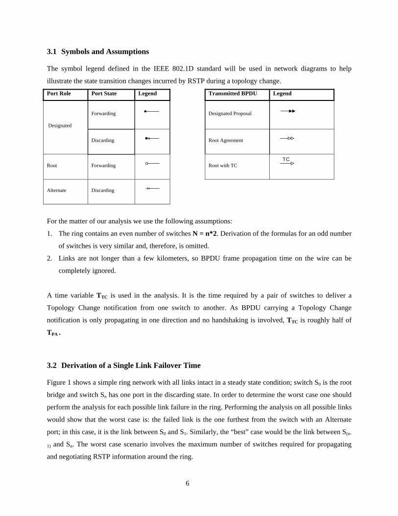
3.1 Symbols and Assumptions
The symbol legend defined in the IEEE 802.1D standard will be used in network diagrams to help
illustrate the state transition changes incurred by RSTP during a topology change.
Port Role Port State Legend Transmitted BPDU Legend
Forwarding
Designated Proposal
Designated
Discarding
Root Agreement
Root Forwarding
Root with TC
TC
Alternate Discarding
For the matter of our analysis we use the following assumptions:
1. The ring contains an even number of switches N = n*2. Derivation of the formulas for an odd number
of switches is very similar and, therefore, is omitted.
2. Links are not longer than a few kilometers, so BPDU frame propagation time on the wire can be
completely ignored.
A time variable TTC is used in the analysis. It is the time required by a pair of switches to deliver a
Topology Change notification from one switch to another. As BPDU carrying a Topology Change
notification is only propagating in one direction and no handshaking is involved, TTC is roughly half of
TPA .
3.2 Derivation of a Single Link Failover Time
Figure 1 shows a simple ring network with all links intact in a steady state condition; switch S0 is the root
bridge and switch Sn has one port in the discarding state. In order to determine the worst case one should
perform the analysis for each possible link failure in the ring. Performing the analysis on all possible links
would show that the worst case is: the failed link is the one furthest from the switch with an Alternate
port; in this case, it is the link between S0 and S1. Similarly, the “best” case would be the link between S(n-
1) and Sn. The worst case scenario involves the maximum number of switches required for propagating
and negotiating RSTP information around the ring.
6

After the link failure, the ring is divided into two segments S0-S-(n-1) and S1-Sn because connectivity
between them is blocked by the Sn’s Alternate port Sn-S-(n-1) . (Figure 2)
S0
Sn
S2S-2
S(n-2)
S1S-1
S-(n-2)
S(n-1)S-(n-1)
Root Bridge
Alternate Port
Traffic source
Traffic destination
. . .. . .
S0
Sn
S2S-2
S(n-2)
S1S-1
S-(n-2)
S(n-1)S-(n-1)
. . . . . .
Figure 2. Figure 1: Ring segments after link failure Steady state before link failure
The following activities are required to restore the ring connectivity – note that the activities are different
for the two segments:
• Segment S0-S-(n-1) does not require any topology reconfiguration because the old path to the Root is
still valid for all switches in that segment.
• Switch Sn must change its former Alternate port role to Root and its former Root port to Designated;
all other switches in segment S1-Sn should swap their Designated and Root port roles.
• Switch Sn must initiate a Topology Change notification which must be propagated from Sn up to S0 so
that S0 will flush its MAC address table on the failed link S0-S1.
Table 1 describes how the above activities will proceed at different time points.
7

Table 1. Time-line of RSTP actions by different switches in the ring (single link failure)
Time Switch acting
Action Description Figure
S0 S0 doesn’t do anything because it is the Root.
TL S1
S1 detects the link failure and immediately ages out its
Root info on port S1-S0 . S1-S0 is S1’s only path to the
Root, so S1 will declare itself as a new root bridge and
start Proposal-Agreement handshaking with S2 .
Figure 3
TL + TPA S2
New Root information comes to S2 from its only path
to the previous Root, so S2 replaces the previous Root
info with the new one, puts S2-S3 to Discarding state,
sends Agreement BPDU to S1 and starts Proposal-
Agreement handshaking with S3 .
Figure 4
… {S3,…,Sn-2} In a similar fashion, the Proposal-Agreement
handshaking will occur on each hop up to S(n-1) . -
TL + (n-2)*TPA Sn-1 {S1,…,Sn-1}all agree about recognizing S1 as Root. Figure 5
Sn
Successful Proposal-Agreement continues until Sn is
reached. As Sn has a better Root (S0) information, it
turn its Alternate Port into Root Port and reply with its
own Proposal rather than Agreement. NOTE: When
changing the former Alternate port role to Root the
switch will put that port to forwarding and send a
Topology Change notification to S-(n-1) .
Figure 6
TL + (n-2+1)*TPA Sn-1 Sn-1 starts Proposal-Agreement handshaking with Sn-2.
Also, approximately at this time Topology Change
notification also reaches S-(n-1) .
-
… {Sn-2,…,S2} The Proposal-Agreement handshaking occurs on each
hop back to S1 (and the Topology Change notification
propagates to S0).
-
TL + (n-2+1)*TPA + (n-2)*TPA S1 All switches agree about the new path to the Root (S0)
and all ports are in Forwarding state. Figure 7
TL + (n-2+1)*TPA + (n-1)*TTC S0 Topology Change Notification reaches S0 and causes
it to flush its MAC address table on port S0-S1 (this is
the purpose of TCN). Network connectivity restored.
Figure 8
8

S0
Sn
S2S-2
S(n-2)
S1S-1
S-(n-2)
S(n-1)S-(n-1)
. . . . . .
S0
Sn
S2S-2
S(n-2)
S1S-1
S-(n-2)
S(n-1)S-(n-1)
. . . . . .
Figure 3. Figure 4.
S1 declares itself as new Root S2 agrees about S1 being Root
S0
Sn
S2S-2
S(n-2)
S1S-1
S-(n-2)
S(n-1)S-(n-1)
S0
. . . . . .
Figure 5.
{S1,…,S(n-1)} all agree about S1 being Root
Sn
S2S-2
S(n-2)
S1S-1
S-(N-2)
S(n-1)S-(n-1)
. . . . . .
TC
Figure 6.
Sn turns its Alternate Port into Root Port and
replies with proper Root (S0) information
9

S0
Sn
S2S-2
S(n-2)
S1S-1
S-(N-2)
S(n-1)S-(n-1)
. . . . . .
Figure 7.
All switches agree about new Root path
Figure 8.
Steady state after network recovery
S0
Sn
S2S-2
S(n-2)
S1S-1
S-(n-2)
S(n-1)S-(n-1)
Root Bridge
Traffic source
Traffic destination
. . . . . .
So the overall failover time is
TL + (n-2+1)*TPA + max( (n-1)*TTC , (n-2)*TPA )
As we explained above, TPA is significantly longer than TTC , and then the overall failover time is
TL + (n-2+1+n-2)*TPA = TL + (2*n-3)*TPA = TL + (N-3)*TPA
3.3 Derivation of a Root Bridge Failover Time
Failure of the root bridge requires electing a new root bridge which adds further complexity compared to
the single link failure analysis. Figure 9 shows the network in steady state before the root bridge fails.
After the root bridge failure, the ring is divided into two segments S-1-S-(n-1) and S1-Sn because
connectivity between them is blocked by the Sn’s Alternate port Sn-S-(n-1) . (Figure 10). Each switch can
have a different bridge priority configured. Determining the worst case failover time demands analyzing
all cases where the new bridge could become any one of the switches in the ring. Repeating the analysis
for all switches would show that the worst case has S1 and S-1 becoming the next best root candidates with
S1 taking precedence over S-1. Table 2 describes how RSTP will proceed at different points in time for the
worst case.
10

S(n-2)
S0
Sn
S2S-2
S1S-1
S-(n-2)
S(n-1)S-(n-1)
. . . . . .
Figure 10.
Ring segments after root bridge failure Figure 9.
Steady state before root bridge failure
S0
Sn
S2S-2
S(n-2)
S1S-1
S-(n-2)
S(n-1)S-(n-1)
. . . . . .
Root Bridge
Alternate Port
Traffic source Traffic destination
Table 2. Time-line of RSTP actions by different switches in the ring (root bridge failure)
Time Switch acting
Action Description Figure
TL S-1 and S1 Each of S1 and S-1 detects the link failure, ages
out its Root info and advertises itself as a new
root bridge.
Figure 11
… {S2,…,Sn-2} and
{S-2,…,S-(n-2)}
Proposal-Agreement handshaking occurs in
parallel on each hop in two segments, up to S(n-1)
and S-(n-1) -
TL + (n-2)*TPA Sn-1 and
S-(n-1)
{S1,…,Sn-1}all agree about S1 being Root, while
{S-1,…,S-(n-1)} agree about S-1 being Root. Figure 12
11

Sn receives proposal BPDUs from Sn-1 and S-(n-1)
at virtually the same time. For the worst case
scenario, we assume that the proposal from Sn-1
is received and processed first (as you will see
below, this case causes certain network
“confusion” and thus requires more RSTP
actions to resolve it).
Since Sn doesn’t have any information about the
S0 failure yet, it will change its old Alternate
Port role to Root Port and “reject” the Sn-1’s
proposal by sending its own proposal with better
but actually obsolete information about S0 . This
info will “confuse” all { Sn-1,…,S1} switches.
Figure 13
Sn
Right after that, Sn will process S-(n-1)’s proposal
about S-1 as Root. As Sn receives that proposal
from its only path to the Root, it immediately
ages out the old Root information and starts
Proposal-Agreement handshaking with Sn-1
again – this time proposing S-1 as Root. The new
Proposal is now fixing the “confusion” just
caused by the previous Proposal about S0 .
Figure 14
TL + (n-2+1+1)*TPA Sn-1 Sn-1 starts Proposal-Agreement handshaking
with Sn-2 about S-1 as Root. -
… {Sn-2,…,S3} The Proposal-Agreement handshaking occurs on
each hop back to S2. -
TL + (n-2+1+1)*TPA + (n-3)*TPA S2 All switches in the ring except S1 erroneously
agree about S-1 being Root. S2 sends Proposal to
S1 about S-1 as Root.
Figure 15
S1 Being a better Root candidate, S1 responds with
its own Proposal about itself as Root. Figure 16
TL + (n-2+1+1)*TPA + (n-3)*TPA
+ TPA S2
Final round of handshaking starts from S2
towards S-1 – this time for the real best Root
candidate S1.
-
… {S3,…,S-2} The Proposal-Agreement handshaking occurs on
each hop all the way to S-1 . -
12

TL + (n-2+1+1)*TPA + (n-3)*TPA
+ TPA + (2*n-3)*TPA S-1
All switches in the network agree about S1 being
Root and all ports are in Forwarding state.
Connectivity is restored.
Figure 17
Note that in the analysis Topology Change notification was not even mentioned because it propagates
along with the initial round of handshaking, i.e. much before the final topology is achieved.
Figure 11.
S1 and S-1 declare themselves as Root
S(n-2)
S0
Sn
S2S-2
S1S-1
S-(n-2)
S(n-1)S-(n-1)
. . . . . .
S(n-2)
S0
Sn
S2S-2
S1S-1
S-(n-2)
S(n-1)S-(n-1)
. . . . . .
Root=S1Root=S-1
Figure 12.
{S1,…,Sn-1 } agree about S1, while
{S-1,…,S-(n-1) } agree about S-1
S(n-2)
S0
Sn
S2S-2
S1S-1
S-(n-2)
S(n-1)S-(n-1)
. . . . . .
Root=S0
Figure 13.
Sn sends obsolete proposal about S0
being Root
Figure 14.
Sn sends new proposal about S-1
being Root
S(n-2)
S0
Sn
S2S-2
S1S-1
S-(n-2)
S(n-1)S-(n-1)
. . . . . .
Root=S0Root=S- Root=S-1
Root=S
0
1
13

Figure 17.
Steady state after network recovery
Sn
S2S-2
S(n-2)
S1S-1
S-(n-2)
S(n-1)S-(n-1)
. . . . . .
Traffic source Traffic destination
S(n-2)
S0
Sn
S2S-2
S1S-1
S-(n-2)
S(n-1)S-(n-1)
. . . . . .
Root=S1
Figure 16.
S1 rejects proposal about S-1 and declares
itself as Root
Figure 15.
All switches except S1 agree about S-1 being
Root
S(n-2)
S0
Sn
S2S-2
S1S-1
S-(n-2)
S(n-1)S-(n-1)
Root=S-1
. . . . . .
14

So the overall root bridge failover time is
TL + (n-2+2)*TPA + (n-3)*TPA + TPA + (2*n-3)*TPA = TL + (4*n – 5)*TPA = TL + (2*N – 5)* TPA
Please note that the described scenario is an uncontrolled theoretical worst case. This extensive failover
time can be easily and significantly reduced by taking a controlled case approach. If Sn’s Bridge Priority
is configured in such a way that it is the best root bridge candidate after the failed S0, the scenario gets
much simpler. Events in the network will proceed like in the uncontrolled case until the step in Figure 12,
but in the Figure 13 step Sn will advertise itself as a Root to both half-ring segments, thus starting a final
round of handshaking. So the failover time gets reduced to
TL + (n-2+1)* TPA + (n-2)* TPA = TL + (2*n – 3)* TPA = TL + (N – 3)* TPA,
which is identical to the formula derived for the single link failure case.
3.4 Link and Root Bridge Recovery
The connectivity recovery mechanism in case of a link or root bridge recovery is different from the link or
root bridge failure case in the following aspects:
1. Link detection time is not included in the network outage time – RSTP activities only start after the
link is detected
2. All links are available for the Root information propagation, so multiple “reconfiguration” of certain
network segments does not occur
As a result, network outage time in the case of a link or root bridge recovery is always shorter than in the
case of a link or Root Ridge failure. Since only the worst case is of importance, link or root bridge
recovery case analysis is omitted.
15

4. Extrapolation to Meshed Networks
As meshed network topology analysis is more complex than that of a ring, the first impression could be
that RSTP performance must be always worse in meshed topology compared to a single ring. However,
that is not generally true although it is in some scenarios.
4.1 Single Link Failure
A meshed network can be looked as a ring network with some inter-switch connections which result in
shortcuts for BPDU propagation. Figure 18 presents a simplified example of this.
Traffic source
Traffic destination
S0
Analyzing this network behavior in the same case of the link S0-S1 failure, shows that RSTP handshaking
steps don’t have to go all the way from S1 to Sn. Information about the root bridge (S0) location can
already be obtained from the switch S(n-2) or S-2 which will make the network recovery faster. An
observation can be made that meshed networks provide shorter paths for RSTP information propagation
which allows handshaking sequence to complete faster. As a result, a meshed network single link failover
time should be same or better than the failover time of the largest outer ring in that network topology
(assuming the given topology does have such an outer ring).
Figure 18.
Sn
S2S-2
S(n-2)
S1S-1
S-(n-2)
S(n-1)S-(n-1)
. . . . . .
Root Bridge
Alternate Port
Alternate Port
Alternate Port
16

4.2 Root Bridge Failure
Unfortunately, the additional complexity of meshed topology causes root bridge failure failover times to
increase compared with the simple ring. The problem of the root bridge failure scenario is that, after the
failure, every switch holding the obsolete Root information is feeding it back to the network, thus
“confusing” all other switches and making them “reject” the right new Root information. The same
problem exists in the ring topology as well but, due to the topology simplicity, there are no loops where
the obsolete information would circulate and the “confusion” is fixed very quickly. This is not the case in
meshed networks.
A meshed network can be looked at as multiple smaller rings interconnected with each other at multiple
points. This topology allows the obsolete Root information to circulate multiple times back and forth
inside and between the smaller rings. The network will not be confused forever - according to the RSTP
standard, the old information will be aged out after it traverses the maximum allowed number of hops
(normally 20). However, the network outage time can last as long as seconds. It is caused by the fact that
multiple switches in the network are continuously busy with processing and forwarding contradictory
BPDUs being continuously received on different ports.
Root bridge failure in a meshed network is very hard to analyze and predict, and a result may be totally
different for every specific topology. The common conclusion is though, that the root bridge failover time
grows exponentially as more redundant paths are added to the network topology. The root bridge failure
in meshed topology is a well recognized problem. Although some proprietary mechanisms are offered to
indirectly improve the RSTP performance, no common solution is known for this case. This is the price
paid for the high level of link redundancy provided by meshed network topology.
17

5. Empirical Performance Data
To corroborate the RSTP analysis, testing of failover performance was done on a test network. The same
worst case setup is used on ring networks with 4 to 40 switches as illustrated in Figures 1 and 9. The
network consists of RuggedSwitchTM RS900 and RSG2100 switches interconnected with 100Base-TX
links. The switches were using the Rugged Operating System (ROSTM) v3.4 operating system that has an
IEEE 802.1D-2004 RSTP implementation. A SmartBits Ethernet packet blaster was used to generate high
rates of traffic and determine the number of dropped frames during the failover event. 45Mbps
unidirectional traffic was generated. No other application was running on the network. The switches were
configured in such way that MAC address tables are not purged by link loss, making the measured
failover times due to RSTP only.
Failover performance was measured for the worst case link failure and root bridge failure. Link failure
was accomplished by simply disconnecting the cable while root bridge failure was done by powering off
the switch. The failover time was calculated by multiplying the number of dropped packets (determined
by the SmartBits) by the time between start of transmission of two consecutive messages (which is a
constant). The measured and analytical failover times are shown in Figure 19 and Table 3.
RSTP Failover Times if Link Fails
0
50
100
150
200
0 10 20 30 40 Number of Switches
[ms]
Failover TimeMeasured
Theoretical UpperBound
Figure 19. Measured vs. theoretical RSTP failover time in ring network if single link fails.
18
19
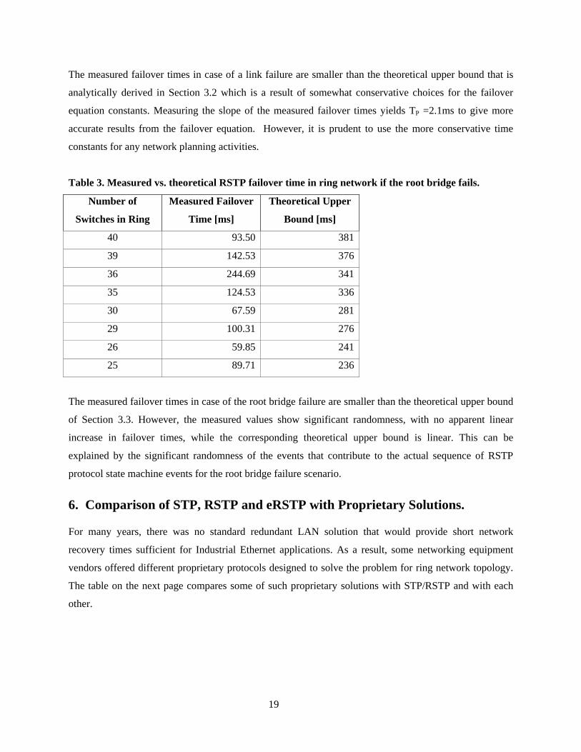
The measured failover times in case of a link failure are smaller than the theoretical upper bound that is
analytically derived in Section 3.2 which is a result of somewhat conservative choices for the failover
equation constants. Measuring the slope of the measured failover times yields TP =2.1ms to give more
accurate results from the failover equation. However, it is prudent to use the more conservative time
constants for any network planning activities.
Table 3. Measured vs. theoretical RSTP failover time in ring network if the root bridge fails.
Number of
Switches in Ring
Measured Failover
Time [ms]
Theoretical Upper
Bound [ms]
40 93.50 381
39 142.53 376
36 244.69 341
35 124.53 336
30 67.59 281
29 100.31 276
26 59.85 241
25 89.71 236
The measured failover times in case of the root bridge failure are smaller than the theoretical upper bound
of Section 3.3. However, the measured values show significant randomness, with no apparent linear
increase in failover times, while the corresponding theoretical upper bound is linear. This can be
explained by the significant randomness of the events that contribute to the actual sequence of RSTP
protocol state machine events for the root bridge failure scenario.
6. Comparison of STP, RSTP and eRSTP with Proprietary Solutions.
For many years, there was no standard redundant LAN solution that would provide short network
recovery times sufficient for Industrial Ethernet applications. As a result, some networking equipment
vendors offered different proprietary protocols designed to solve the problem for ring network topology.
The table on the next page compares some of such proprietary solutions with STP/RSTP and with each
other.

Single ring link failover time (for different number of
switches) Protocol Vendor
Can be used in multi-vendor environment
Max Bridge Diameter Topology
10 15 20
STP IEEE Standard Yes 40 Any >30s RSTP (802.1w) IEEE Standard Yes 40 Any Several seconds
HiPER Ring [4],[5] Hirschmann No Virtually unlimited Ring 200-500ms, independent of
number of switches
Turbo Ring [4],[6] Moxa No Virtually unlimited Ring <200ms <250ms <300ms
S-Ring [8] GarrettCom No data not available Ring <250ms
RS-Ring [8] GarrettCom No data not available Ring <100ms
RapidRingTM [7]
Contemporary Controls No 50 Ring <300ms
RSTP (802.1D-2004) IEEE Standard Yes 40 Any <50ms <75ms <100ms
eRSTPTM RuggedCom enhancements to IEEE Standard
Yes 160 Any <50ms <75ms <100ms
NOTE: proprietary solutions data is derived from the specified reference documents.
20

7. Conclusion
RSTP performance is both predictable and repeatable for failure and recovery of switches and cabling in a
ring topology. Precise equations can be used to determine the network outage time; for a ring of twenty
switches, worse case failover times on the order of 100 milliseconds are quite realistic - typical RSTP
performance is much better. Unfortunately, most literature to date states RSTP failover performance of
several seconds based on results from the older IEEE 802.1w RSTP. The analysis in this paper hopefully
will put this misconception to rest and give confidence to designers of such networks; RSTP is more than
capable of being deployed in very demanding automation networks.
RSTP has other advantages over the ‘ring’ protocols such as the ability to support any network topology
including mesh which allows for an even greater degree of redundancy. RSTP tends to have faster not
slower network recovery times. RSTP works in a multi-vendor environment and is supported by all the
major switch vendors. Finally, RSTP was created by and is supported by an international standards
organization which ensures scrutiny by peers and future harmony with the myriad of other Ethernet
standards under development. RSTP is an excellent solution for many mission critical industrial Ethernet
applications which is why it has seen so much success to date and why it will continue to be the dominant
Ethernet redundancy protocol in the future.
8. References
[1] ANSI/IEEE Std 802.1D, 1998 Edition
[2] ANSI/IEEE Std 802.1w, 2001 Edition
[3] ANSI/IEEE Std 802.1D, 2004 Edition
[4] “High Availability Networks”, The Industrial Ethernet Book, [5] M. Schaub, H. Kell, “Redundancy Process with Hirschmann Switches”, ComConsult
Kommunikationstechnik GmbH, 2003, [6] “Stay Connected with Turbo Ring”, Moxa Technologies, Inc., [7] “RapidRingTM – Redundancy from Contemporary Controls”, Contemporary Control Systems, Inc.,
2004
[8] “Secure Web Management User Guide for Magnum 6K family of Switches, Release 3.6”, GarrettCom, Inc.
21

22
9. Biographies
Michael Pustylnik is a senior software engineer and project leader for RuggedCom, Inc., a leading manufacturer of industrially hardened communications technology for mission-critical applications in harsh environments. Michael has over 10 years of experience in developing embedded software for wireless and wired communications. Prior to joining RuggedCom Michael was a software project leader for Motorola Communications division where he developed mobile and portable wireless communication equipment. Michael graduated from the Technion - Israel Institute of Technology in 1994 with a Bachelor of Electrical Engineering degree majoring in communications.
Mira Zafirovic-Vukotic is a quality manager of RuggedCom Inc. Mira has over 20 years experience in communication protocols, performance analysis, system verification, security and control systems. Her previous employers were M. Pupin Institute from Belgrade, and Agilent Technologies. Mira has graduated from University of Belgrade, Faculty of Mathematics, major in computer science, in 1981 and obtained PhD in technical sciences from University of Twente, the Netherlands in 1988. Mira has authored 6 IEEE/ACM journal papers related to communication systems. She is a senior member of IEEE and member of IEC TC57 WG15.
Roger Moore is the Engineering Vice President of RuggedCom, Inc. Prior to founding RuggedCom,
Roger was a project manager for General Electric’s Power Management division where he developed advanced protective relaying systems and substation automation technology. Roger graduated from the University of Toronto in 1990 with a Bachelor of Applied Science degree majoring in computer science and physics. He holds patents related to advances in communications and protective relaying technology. He is also an active member of the IEEE and is involved in developing the new IEEE 1588 standard for precision time synchronization of devices via a communications network.