peristaltic industrial hose pump · been approved by the manufacturer. for further details...
TRANSCRIPT
Peristaltic Industrial Hose PumpATEX Instruction Manual
Version 1.0v-07/2019
Print-No. 01
Dura 05-55

ATEX Instruction ManualDura 05-55
Version 1.0v-07/2019 2 | Page
Version 1.0v-07/2019Print-No. 01
ATEX Instruction ManualDura 05-55
The information in this document is essential for the safe operation and maintenance of Verder-flex® industrial range of pumps in ATEX environment. This document must be read and under-stood thoroughly prior to installation of unit, electrical connection and commissioning.
ATEX Instruction ManualDura 05-55
Version 1.0v-07/2019 3 | Page
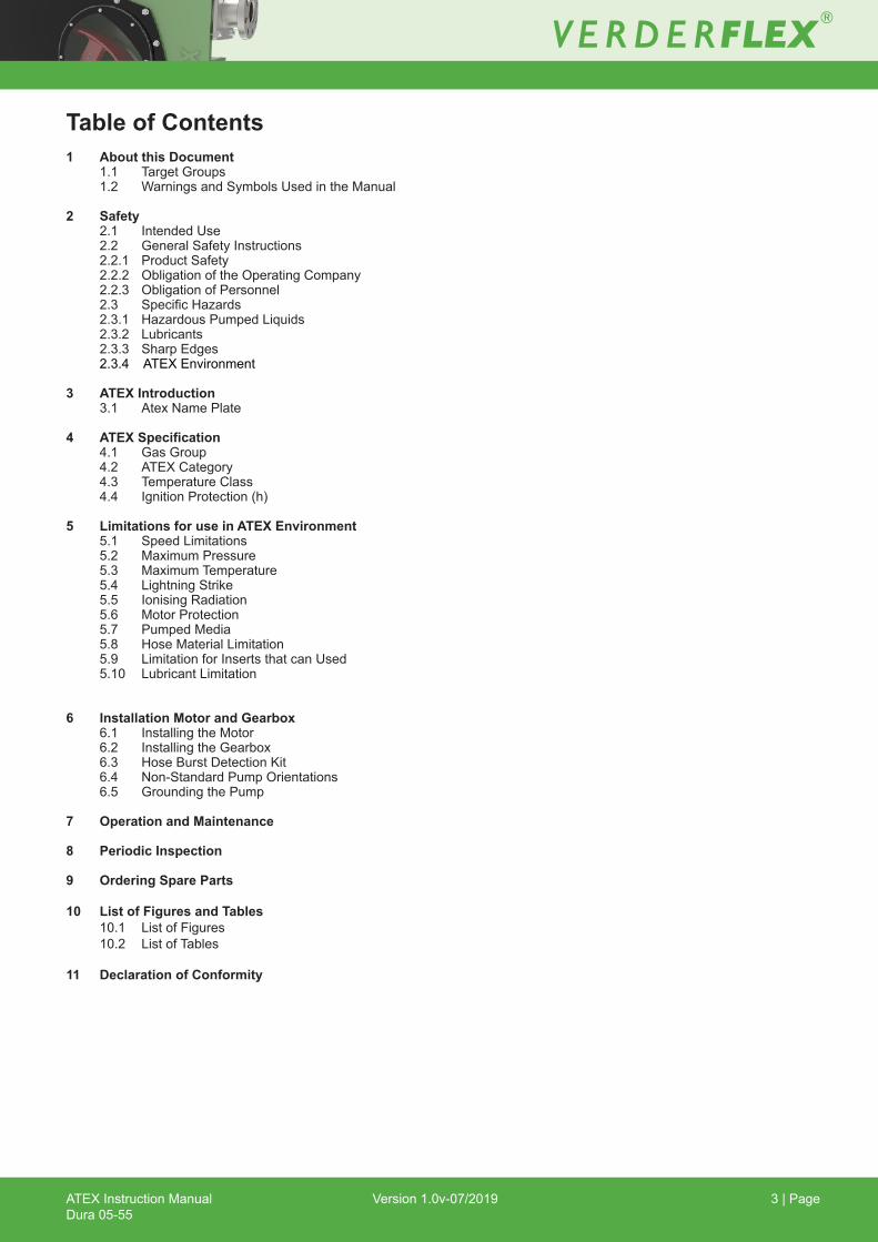
1 About this Document 1.1 Target Groups 1.2 Warnings and Symbols Used in the Manual
2 Safety 2.1 Intended Use 2.2 General Safety Instructions 2.2.1 Product Safety 2.2.2 Obligation of the Operating Company 2.2.3 Obligation of Personnel 2.3 SpecificHazards 2.3.1 HazardousPumpedLiquids 2.3.2 Lubricants 2.3.3 Sharp Edges 2.3.4 ATEX Environment
3 ATEX Introduction 3.1 AtexNamePlate
4 ATEXSpecification 4.1 Gas Group 4.2 ATEX Category 4.3 Temperature Class 4.4 Ignition Protection (h)
5 Limitations for use in ATEX Environment 5.1 SpeedLimitations 5.2 MaximumPressure 5.3 MaximumTemperature 5.4 LightningStrike 5.5 Ionising Radiation 5.6 Motor Protection 5.7 Pumped Media 5.8 HoseMaterialLimitation 5.9 LimitationforInsertsthatcanUsed 5.10 LubricantLimitation
6 Installation Motor and Gearbox 6.1 Installing the Motor 6.2 InstallingtheGearbox 6.3 HoseBurstDetectionKit 6.4 Non-Standard Pump Orientations 6.5 Grounding the Pump
7 Operation and Maintenance
8 Periodic Inspection
9 Ordering Spare Parts
10 List of Figures and Tables 10.1 ListofFigures 10.2 ListofTables
11 Declaration of Conformity
Table of Contents
ATEX Instruction ManualDura 05-55
Version 1.0v-07/2019 4 | Page
Thismanual isaguidelineforqualifiedusersforthesafeoperationandmaintenanceofVerderflex®pumpsworkinginATEXenvironments. This is a supplementary document to the operating manual. The operating manual must be read and understood both by the installing personnel and the responsible trained personnel / operators prior to following additional guidelines in this ATEX instruction manual.
Instructionsinthismanualshouldbereadinconjunctionwithinstructionsandguidelinesinmotorandgearboxoperatingmanualsand ATEX guidelines.
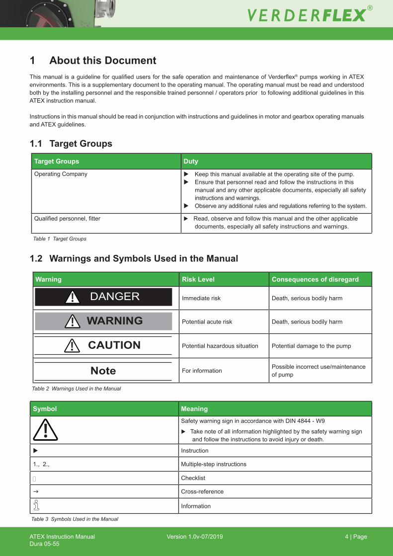
1 About this Document
1.1 Target Groups
Table 1 Target Groups
Table 3 Symbols Used in the Manual
1.2 Warnings and Symbols Used in the Manual
Table 2 Warnings Used in the Manual
Target Groups Duty
Operating Company u Keepthismanualavailableattheoperatingsiteofthepump.u Ensure that personnel read and follow the instructions in this
manual and any other applicable documents, especially all safety instructions and warnings.
u Observe any additional rules and regulations referring to the system.
Qualifiedpersonnel,fitter u Read, observe and follow this manual and the other applicable documents, especially all safety instructions and warnings.
Warning Risk Level Consequences of disregard
Immediaterisk Death, serious bodily harm
Potentialacuterisk Death, serious bodily harm
Potentialhazardoussituation Potential damage to the pump
Forinformation Possible incorrect use/maintenance of pumpNote
CAUTION
WARNING
DANGER
Symbol Meaning
Safety warning sign in accordance with DIN 4844 - W9
u Takenoteofallinformationhighlightedbythesafetywarningsignand follow the instructions to avoid injury or death.
u Instruction
1., 2., Multiple-step instructions
[ Checklist
g Cross-reference
Information

ATEX Instruction ManualDura 05-55
Version 1.0v-07/2019 5 | Page
2 Safety The manufacturer does not accept any liability for damage resulting from disregard of this documentation.
2.1 Intended Useu Only use the pump to handle compatible fluids as
recommended by the manufacturer (g 5 Limitations foruse in ATEX Environment.
u Adhere to the operating limits.u Consult the manufacturer regarding any other use of the
pump.u Pumpsdeliveredwithoutamotormustbefittedwithamo-
tor in accordance with the provisions of EC Machinery Di-rective 2006/42/EC.
Prevention of obvious misuse (examples)u Note the operating limits of the pump with regard to tem-
perature,pressure,flowrateandmotorspeed(g5Limita-tions for use in ATEX Environment.
u Do not operate the pump with any inlet/outlet valves closedu Only install the pump as recommended in this manual.
Forexample,thefollowingarenotallowed: – Installing the pump without proper support.– Installationintheimmediatevicinityofextremehotor
cold sources.
2.2 General Safety Instructions Observe the following regulations before carrying outanywork.
2.2.1 Product Safety• These operating instructions contain fundamental infor-
mation which must be complied with during installation, operation and maintenance. Therefore this operating manual must be read and understood both by the installing personnel and the responsible trained personnel / operators prior to installation and commissioning, and it mustalwaysbekepteasilyaccessiblewithintheoperatingpremises of the machine.
Not only must the general safety instructions laid down in this chapter on “Safety” be complied with, but also the safetyinstructionsoutlinedunderspecificheadings.
• Operate the pump only if it and all associated systems are in good functional condition.
• Only use the pump as intended, fully aware of safety and riskfactorsinvolvedandtheinstructionsinthismanual.
• Keep this manual and all other applicable documentscomplete, legible and accessible to personnel at all times.
• Refrain from any procedure or action that would pose a risktopersonnelorthirdparties.
• In the event of any safety-relevant faults, shut down the pump immediately and have the malfunction corrected by qualifiedpersonnel.
• Theinstallationofthepumpmustcomplywiththerequire-ments of installation given in this manual and any local, national or regional health and safety regulations.
2.2.2 Obligation of the Operating Company
Safety-conscious operation• Ensure that the following safety aspects are observedandmonitored: – Adherence to intended use – Statutory or other safety and accident-prevention regulations – Safety regulations governing the handling of hazardoussubstancesifapplicable – Applicable standards and guidelines in the country where the pump is operated• Make personal protective equipment available pertinent to operation of the pump.
Qualifiedpersonnel• Ensurethatallpersonneltaskedwithworkonthepump have read and understood this manual and all other applicable documents, including the safety, maintenance and repair information, prior to use or installation of the pump.• Organize responsibilities, areas of competence and the supervision of personnel.• Have all work carried out by specialist technicians only.• Ensure that trainee personnel are under the supervision of specialist technicians at all times when workingwiththepump.
Safety equipment Providethefollowingsafetyequipmentandverifyits functionality:
– For hot, cold and moving parts: safety guardingshould be provided by the operating company.
– Forpotentialbuildupofelectrostaticcharge:ensureappropriategroundingifandwhenrequired.
Warranty The warranty is void if the customer fails to follow any
Instruction, Warning or Caution in this document. Verder hasmadeeveryefforttoillustrateanddescribetheprod-uct in this document. Such illustrations and descriptions arehowever,forthesolepurposeofidentificationanddo notexpressorimplyawarrantythattheproductsaremer-chantableorfitforaparticularpurpose,orthattheprod-ucts will necessarily conform to the illustration or descrip-tions.
Obtain the manufacturer’s approval prior to carrying out anymodifications, repairs or alterations during the war-ranty period. Only use genuine parts or parts that have been approved by the manufacturer.
Forfurtherdetailsregardingwarranty,refertotermsandconditions.
ATEX Instruction ManualDura 05-55
Version 1.0v-07/2019 6 | Page
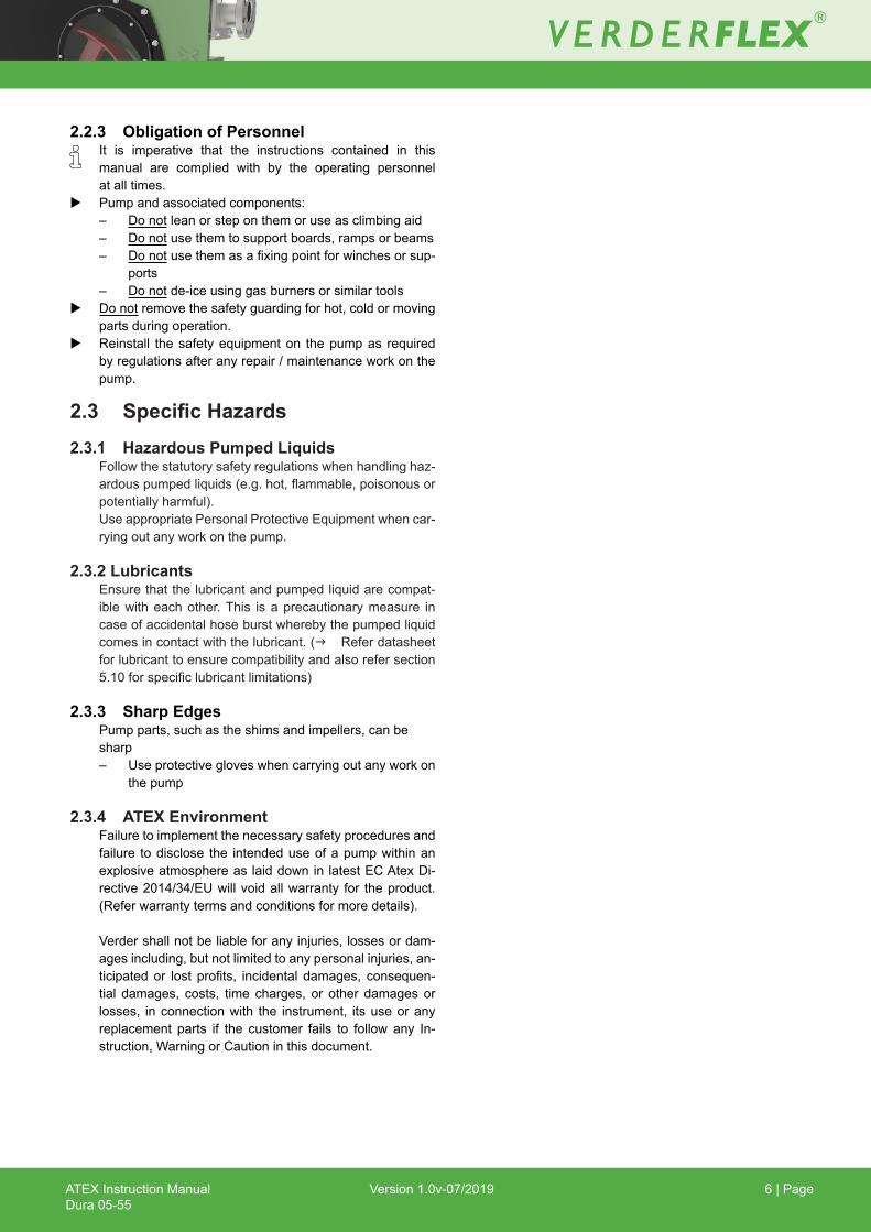
2.2.3 Obligation of Personnel It is imperative that the instructions contained in this
manual are complied with by the operating personnel at all times.
u Pumpandassociatedcomponents:– Do not lean or step on them or use as climbing aid– Do not use them to support boards, ramps or beams– Do notusethemasafixingpointforwinchesorsup-
ports– Do not de-ice using gas burners or similar tools
u Do not remove the safety guarding for hot, cold or moving parts during operation.
u Reinstall thesafetyequipmenton thepumpas requiredbyregulationsafteranyrepair/maintenanceworkonthepump.
2.3 SpecificHazards2.3.1 HazardousPumpedLiquids Followthestatutorysafetyregulationswhenhandlinghaz-
ardouspumpedliquids(e.g.hot,flammable,poisonousorpotentially harmful).
UseappropriatePersonalProtectiveEquipmentwhencar-ryingoutanyworkonthepump.
2.3.2 Lubricants Ensurethatthelubricantandpumpedliquidarecompat-
ible with each other. This is a precautionary measure in caseofaccidentalhoseburstwherebythepumpedliquidcomes in contact with the lubricant. (g Refer datasheet for lubricant to ensure compatibility and also refer section 5.10forspecificlubricantlimitations)
2.3.3 Sharp Edges Pump parts, such as the shims and impellers, can be
sharp– Useprotectivegloveswhencarryingoutanyworkon
the pump
2.3.4 ATEX Environment Failuretoimplementthenecessarysafetyproceduresand
failure to disclose the intended use of a pump within an explosiveatmosphereaslaiddowninlatestECAtexDi-rective 2014/34/EU will void all warranty for the product. (Refer warranty terms and conditions for more details).
Verder shall not be liable for any injuries, losses or dam-ages including, but not limited to any personal injuries, an-ticipatedor lost profits, incidental damages, consequen-tial damages, costs, time charges, or other damages or losses, in connection with the instrument, its use or any replacement parts if the customer fails to follow any In-struction, Warning or Caution in this document.

ATEX Instruction ManualDura 05-55
Version 1.0v-07/2019 7 | Page
3 ATEX Introduction ATEX assessment for the Dura 05-55 pumps are based on
EquipmentgroupIIcategory2,RefBSEN13463-1:2009and in compliance with EU ATEX Directive 2014/34/EU, commonlyreferredtoastheATEX(“Atmosphèresexplosi-bles”) “product” directive, applicable from 20 April 2016, which replaces the previous Directive 94/9/EC.
Verder strongly recommends the user to ensure the ATEX ratedequipment is installedandoperated inaccordancewithATEX“workplace”Directive1999/92/EC.Anyassoci-atedequipmentinstalledorusedwithinanExplosiveenvi-ronment should be rated to appropriate ATEX standard.
Dura 05-35Dura 45-55
Target GroupsDuty
6.5.
2.1. 3.
7. 8. 9.
4.
6. Gas Group 7. Temperature Class 8.ATEXCategory: ‘G’ for Gas ‘D’ for Dust9 . Ambient Temperature Range
1. Pump Type 2. Serial Number3. Year of Manufacture4.TechnicalFileReference Number 5. Ignition Protection
Figure 1 ATEX Name Plate
3.1 ATEX Name Plate
ATEX Instruction ManualDura 05-55
Version 1.0v-07/2019 8 | Page
4 ATEXSpecification
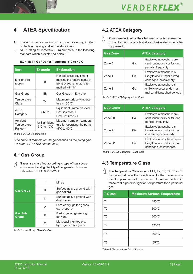
1. The ATEX code consists of the group, category, ignition protectionmarkingandtemperatureclass.
2. ATEXratingofVerderflexDurapumpsistothefollowingstandardwhichisexplainedbelow:
EX h IIB T4 Gb / Db for T ambient -5°C to 40°C
*The ambient temperature range depends on the pump type. (g refer to 3.1 ATEX Name Plate)
4.1 Gas Group Gasesareclassifiedaccordingtotypeofhazardous
environmentandignitabilityofthegas/airmixtureasdefinedinEN/IEC60079-21-1.
Table 4 ATEX Classification
Item Example Explanation
Ignition Pro-tection h
Non-ElectricalEquipmentmeetingtherequirementsofENISO80079-36:2016ismarkedwith“h”.
Gas Group IIB Gas Group II - Ethylene
Temperature Class T4 Maximumsurfacetempera-
ture < 135 °C
ATEX Category Gb/Db
EquipmentProtectionlevel:Gb:Gaszone1 Db:Dustzone21
Ambient Temperature Range *
for T ambient -5°C to 40°C
Maximumambienttempera-ture for operating the pump -5°C to 40°C
4.2 ATEX Category Zonesaredecidedbythesitebasedonariskassessment
ofthelikelihoodofapotentiallyexplosiveatmospherebe-ing present.
4.3 Temperature Class
The Temperature Class rating of T1, T2, T3, T4, T5 or T6 forgases,indicatestheclassificationforthemaximumsur-face temperature for the device and therefore the the dis-tance to the potential ignition temperature for a particular gas.
Gas Group
I Mines
II Surface above ground with gashazard
III Surface above ground with dusthazard
Gas Sub Group
A Lesseasilyignitedgasese.g. propane
B Easily ignited gases e.g ethylene
C Most easily ignited e.g. hydrogen or acetylene
Table 5 Gas Group Classification
Gas Zone ATEX Category
Zone 0 GaExplosiveatmospherepre-sent continuously or for long periods,frequently
Zone 1 GbExplosiveatmosphereislikelytooccurundernormalconditions, occasionally
Zone 2 GcExplosiveatmosphereisunlikelytooccurundernor-mal conditions, short periods
Table 6 ATEX Category - Gas Zone
Dust Zone ATEX Category
Zone 20 DaExplosiveatmospherepre-sent continuously or for long periods,frequently
Zone 21 DbExplosiveatmosphereislikelytooccurundernormalconditions, occasionally
Zone 22 DcExplosiveatmosphereisun-likelytooccurundernormalconditions, short periods
Table 7 ATEX Category - Dust Zone
T Class Maximum Surface Temperature
T1 450°C
T2 300°C
T3 200°C
T4 135°C
T5 100°C
T6 85°C
Table 8 Temperature Classification

ATEX Instruction ManualDura 05-55
Version 1.0v-07/2019 9 | Page
4.4 Ignition Protection (h) Inenvironmentswithanexplosiveatmosphere,ignitionprotectioncategoriesservetopreventignitionbynotreachinghigh
temperatures.Theignitionprotectioncategoriesaredistinguishedaccordingtothetypeandfunctionoftheequipmentandtheprobabilityanexplosiveatmospherewilloccur.
Theignitionhazardassessmentidentifiessourcesofignitionandthesecanthenbedealtwithinturn,throughcompliancewith EN ISO 80079, (greferto“IgnitionHazardAssessment”documentprovidedaspartoftheATEXpackforfulldetailsofcompliance).
IgnitionHazard MeasuresAppliedtoPreventtheIgnitionSourceBecomingEffec-tive
Potential Ignition Source
Description / Basic Cause (which causes originate
which ignitionhazard)
Reason forAssessment
Description of the MeasureApplied
Basis Citation of Standard
Technical Rules
HotSurface
– Lossesdissipateintoheat.
The pump has amaximumtemperature during normal operational conditions.
u Maximumtemperatureachieved during testing.
u HProtorandmaximumratedpressure applied.
u Test results recorded .u Limitationsonmediumtem-
peratureandMaximumpermit-ted pump speed.
EN80079-36:20166.2EN80079-36:20168.2EN80079-36:201610
– Over speed– Excesspressure-discharge– Operating outside of speci-
fiedenvironmentalcondi-tions
Exceedingoper-ating tempera-ture.
u Complywithspecifications. EN80079-36:201610EN80079-37:20165
– BearingwearExceedingoper-ating tempera-ture.
u Bearinglifefarinexcessofthedesign parameters.
u Maintenance procedure to check.
EN80079-36:201610EN80079-37:20165
– Excesspressure-suction
– Low/poorlubricant– Seal failure leading to bear-
ing wear from lubricant loss
Exceedingoper-atingtemperature.Premature hosefailure.
u Maintenance and installation instructions.
u Requirementtousemotoroverload relay.
u Motor supplied with PTCs.u Factorofsafetyonsurface
temperature limit allows for substantial temperature rise.
EN80079-36:201610EN80079-37:20165EN80079-37:20166
– Swelling of hose in the pres-ence of particular solvents
May cause overtemperature
u The manufacture’s instruc-tions list of solvents which are knowntobecompatible.
u Requirementtousemotorprotection relay.
u Motors supplied with PTCs.
EN80079-36:201610
Mechanical Sparks
– Externalimpact,mechanicalfailure
Potential impact from other source, falling object, been struckbymov-ing object.
u Material of manufacture is cast iron having less than 125J impact energy
EN80079-36:20166.4.2.2
Flames,HotGases u Noflamingparts
Table 9 Ignition Protection (continued)

ATEX Instruction ManualDura 05-55
Version 1.0v-07/2019 10 | Page
IgnitionHazard MeasuresAppliedtoPreventtheIgnitionSourceBecomingEffective
Potential Ignition Source
Description / Basic Cause (which causes
originatewhich ignition
hazard)
Reason forAssessment
Description of the MeasureApplied
Basis Citation of Standard
Technical Rules
ElectricalEquipment
– Electric motor inside the assembly
Electricalequip-ment is a pos-sible ignitionsource
u Onlyelectricalequipmentwithcertificationofconformityisused
IEC 60079 series
Stray Electrical, Currents and Cathodic Cor-rosionProtection
u No stray currents or cathodic corrosion
Static Electricity
– Static build up generat-ingspark Hose u Static dissipative
EN80079-36:20166.7.5– Static build up generat-
ingspark
Plastic window,potentialriskduring cleaning a static build up may occur. Nocharging duringnormal opera-tion.
u Apply Cat 3 restrictions, if Cat 2 needed then change mate-rial of the window.
EN13463-1:2009,6.7.3
Lightning – Lightningstrike u End user to assess and pro-tectequipmentaccordingly EN80079-36:201610
Electromag-netic Waves u Not relevant
Ionising Radia-tion – Use in radioactive area u Not relevant, not approved for
use in radioactive area EN80079-36:201610
HighFrequencyRadiation u Not relevant
Ultrasonics u Not relevant
AdiabaticCompression u Not relevant
Mechanicalstrength
– Impact
Potential impact from other source, falling object, been struckbymov-ing object.
u Main housing cast iron, no aluminium or similar to the external,plasticwindowfrontmountedbutofathicknesstowithstand impacts up to 7Nm see tests
EN80079-36:20168.3.1
– Hoseburst
Pressure in cas-ing too high.Occluded pumpdischarge
u Use the Verder recommended ATEX rated hose burst sensor
EN80079-36:201610EN80079-37:20165EN80079-37:20166
– Housingventblocked Pressure in cas-ing too high. u Clean regularly EN80079-36:201610
– Dust collection on horizontalsurfaces
May cause overtemperature.
u Unlikelyonpumpcasingbe-cause of its geometry
u Regular maintenance to help ensure all surfaces remain clean
EN80079-36:201610
Table 9 Ignition Protection (continued)

ATEX Instruction ManualDura 05-55
Version 1.0v-07/2019 11 | Page
IgnitionHazard MeasuresAppliedtoPreventtheIgnitionSourceBecomingEffective
Potential Ignition Source
Description / Basic Cause (which causes
originatewhich ignition
hazard)
Reason forAssessment
Description of the MeasureApplied
Basis Citation of Standard
Technical Rules
Mechanicalstrength – Rotor failure
Rotor failure causing over temperature in motor
u Requirementtousemotorpro-tection relay.
u Motors supplied with PTCs.EN80079-36:201610
ChemicalReaction
– Pump materials incom-patible with pumped media
Hoseburstexposingcasing to media
u End user/ sales applications engineer to ensure awareness of pump construction and compatibility of hose material with pumped media.
EN80079-36:201610
Table 9 Ignition Protection
ATEX Instruction ManualDura 05-55
Version 1.0v-07/2019 12 | Page
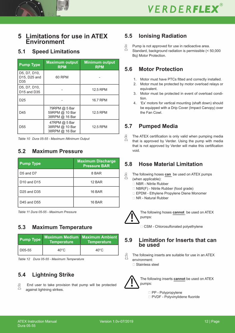
5 Limitations for use in ATEX Environment
5.1 Speed Limitations
5.2 Maximum Pressure
5.3 Maximum Temperature
5.4 Lightning StrikeEnd user to take provision that pumpwill be protectedagainstlightningstrikes.
5.5 Ionising RadiationPump is not approved for use in radioactive area.Standard,backgroundradiationispermissible(<50,000Bq)MotorProtection.
5.6 Motor Protection1. MotormusthavePTCsfittedandcorrectlyinstalled. 2. Motor must be protected by motor overload relays or
equivalent. 3. Motor must be protected in event of overload condi-
tion. 4. ‘Ex’motorsforverticalmounting(shaftdown)should
beequippedwithaDripCover(ImpactCanopy)overtheFanCowl.
5.7 Pumped Media TheATEXcertificationisonlyvalidwhenpumpingmedia
that is approved by Verder. Using the pump with media thatisnotapprovedbyVerderwillmakethiscertificationvoid.
5.8 Hose Material LimitationThe following hoses can be used on ATEX pumps(whenapplicable):NBR-NitrileRubberNBR(F)-NitrileRubber(foodgrade)EPDM-EthylenePropyleneDieneMonomerNR-NaturalRubber
The following hoses cannot be used on ATEXpumps:
CSM-Chlorosulfonatedpolyethylene
5.9 Limitation for Inserts that can be usedThe following inserts are suitable for use in an ATEXenvironment:Stainlesssteel
The following inserts cannot be used on ATEXpumps:
PP-PolypropylenePVDF-Polyvinylidenefluoride
Pump Type Maximum output RPM
Minimum output RPM
D5, D7, D10, D15, D25 and D35
60 RPM -
D5, D7, D10, D15 and D35 - 12.5 RPM
D25 - 16.7 RPM
D4579RPM@5Bar59RPM@10Bar38RPM@16Bar
12.5 RPM
D5547RPM@5Bar38RPM@10Bar38RPM@16Bar
12.5 RPM
Table 10 Dura 05-55 - Maximum /Minimum Output
Pump Type Maximum Discharge Pressure BAR
D5 and D7 8BAR
D10 and D15 12 BAR
D25 and D35 16 BAR
D45 and D55 16 BAR
Table 11 Dura 05-55 - Maximum Pressure
Pump Type Maximum Medium Temperature
Maximum Ambient Temperature
D05-55 40°C 40°C
Table 12 Dura 05-55 - Maximum Temperature

ATEX Instruction ManualDura 05-55
Version 1.0v-07/2019 13 | Page
5 Limitations for use in ATEX Environment (continued)
5.10 Lubricant LimitationThe following lubricants are approved for use on VerderATEXDurapumps:VerderlubeblueVerderlubeclear
Danger of explosion due to incompatible liquidsVerderlube is glycerine based lubricant and therefore cannot be usedinapplicationsthatinvolvestrongoxidizers.u It is incompatible with hydrogen peroxide, potassium
permanganate, nitric acid + sulfuric acid, perchloric acid + lead oxide, acetic anhydride, aniline + nitrobenzene,Ca(OCl)2,CrO3,F2+PbO,KMnO4,K2O2,AgClO4andNaH.
u Itreactswithaceticacid,potassiumperoxide,sodiumper-oxide,hydrochloricacid,(HClO4+PbO)andNa2O2.Con-tactwithpotassiumchloratemaybeexplosive.
Ensure Verderlube is not used as lubricant in applications that involve theabovechemicals toavoidaccidentalmixturewithpumped media in case of accidental hose burst.
The following lubricant cannot be used on ATEXpumps:
Verdersil
6 Installation of Associated Components
Beforeinstallingthepump,alwayschecktheidentifica-tion plate of the pump. TheATEXclassificationmustcorrespondwiththeconditionsoftheworkingenvironment.
6.1 Installing the Motor1. Make sure themotor is suitable for use in a potentially
explosiveenvironment.2. Make sure that the motor is properly connected to the
power supply. Refer to the motor manual for the appropri-ate instructions.
Earth connectionu The power supply must include an earth connection.
6.2 Installing the Gearbox1. Makesurethegearboxissuitableforuseinapotentially
explosiveenvironment.2. Refer to the documentation of the gearbox for specific
productinformationaboutoperatinginapotentiallyexplo-sive environment.
6.3 Hose Burst Detection KitIt is essential to use ATEX rated hose burst detection sen-sors to detect a potentially dangerous situation in time.
Use similar of higher ATEX rated devices with pumpu Only use sensors that are approved by ATEX standards!
Theclassificationshouldbesimilarorhigherthanthatofthe pump.
6.4 Non-Standard Pump OrientationsThere may be cases where the lubricant level cannot be visually monitored through the inspection window such as whenthepumpisfittedwithmetalinspectionwindows.
In these cases the customer should ensure that the pumps are installed with appropriated ATEX rated hose burst de-tectionkitforadditionalprotection(g refer to section 6.3).
6.5 Grounding the PumpThe pump should be grounded before operation. This can be done either through motor earth wiring or alternately by grounding through the base frame.
DANGER
WARNING
WARNING
CAUTION

ATEX Instruction ManualDura 05-55
Version 1.0v-07/2019 14 | Page
7 Operation and Maintenance
Refer “Operation and maintenance manual” forinstructions on use and maintenance of the pump units.
8 Periodic Inspection1. Carry out the periodic inspections as given in the operat-
ing manual of the pump2. In caseofoperating thepump inapotentiallyexplosive
environment,periodicallyinspectpumpfor:– Fluidleakage– Lubricantlevel– Hoseburstdetector– Surface temperatures– Dust deposits (if any)– Bearings
9 Ordering Spare PartsFortrouble-freereplacementintheeventoffaults,werec-ommendkeepingsparepartsavailableonsite.
The following information is mandatory when ordering sparesforATEXratedpump:– If pump is ATEX rated, clearly mention that at the time of
ordering– Indicate the ATEX rating of the unit– Pump model– Year of manufacture– Part number– Serial number

ATEX Instruction ManualDura 05-55
Version 1.0v-07/2019 15 | Page
10 List of Figures and Tables
10.1 List of Figures
Figure1 ATEX Name Plate 3
10.2 List of Tables
Table 1 Target Groups 1.1Table 2 Warnings Used in the Manual 1.2Table 3 Symbols Used in the Manual 1.2Table4 ATEXClassification 4Table5 GasGroupClassification 4.1Table 6 ATEX Category - Gas Zone 4.2Table 7 ATEX Category - Dust Zone 4.2Table8 TemperatureClassification 4.3Table 9 Ignition Protection 4.4Table10 Dura05-55-Maximum/MinimumOutput 5.1Table11 Dura05-55-MaximumPressure 5.2Table12 Dura05-55-MaximumTemperature 5.3Table 13 Declaration of Conformity 11

ATEX Instruction ManualDura 05-55
Version 1.0v-07/2019 16 | Page
Table 13 Declaration of Conformity
EC declaration of conformity according to machinery directive, appendix II A
We,
VERDERLtd.,Unit3CaliforniaDrive,Castleford
herebydeclarethatthefollowingmachineadherestotherelevantECdirectivesdetailedbelow:
Designation Dura 05-55 ECDirectives:• Machinery Directive (2006/42/EC) • EquipmentintendedforuseinPotentiallyExplosiveAtmospheres(ATEX)2014/34/EU
Dura 5-35, 45-55Classification,h IIB T4 Gb for T ambient -5°C to 40°CClassification,h IIB T4 Db for T ambient -5°C to 40°C
TechnicalReferenceFile:• BASEEFA18ATEX0155DR
NotifiedBody:• Baseefa1180BuxtonUK
On behalf of Verder, I declare that on the date the equipment accompanied by this declaration was sold, the equipment conforms to all technical and regulatory requirements of the above listed direc-tives. Manufacturer VERDERLtd.
Unit 3 California Drive Castleford WF105QHUK
Date: 01/07/2019 Company stamp / signature:
Anthony Beckwith Head of Development/Construction
Company stamp / signature:
Paul Storr Head of Quality
11 EC Declaration of Conformity