peristaltic oem tube pump - verderflex · safety warning sign in accordance with din 4844 - w9 take...
TRANSCRIPT

Operating Manual Steptronic
Version 1.0v-01/2016
Print-No. 01
Peristaltic OEM Tube Pump

Steptronic 1.0v-01.2016
Version 1.0v-01/2016Print-No. 01
2 | Page
Verderflex Steptronic
The information in this document is essential for the safe operation and servicing of Verderflex®
Steptronic family of pumps. This document must be read and understood thoroughly prior to installation of unit, electrical connection and commissioning.

Steptronic 1.0v-01.2016
1. About this document 1.1 Target groups 1.2 Warnings and symbols
2. Safety 2.1 Intended use 2.2 General safety instructions 2.2.1 Product safety 2.2.2 Obligation of the operating company 2.2.3 Obligation of personnel 2.3 Specific hazards 2.3.1 Hazardous pumped liquids 2.3.2 Sharp edges
3. Layout and function 3.1 Design details 3.2 Name plate 3.3 Layout - Steptronic Mini-Load Cased Version 3.4 Layout - Steptronic EZ-Head Cased Version 3.5 Layout - Steptronic Mini-Load Panel Mounted 3.6 Layout - Steptronic EZ head Panel Mounted 3.7 Mounting Panel - Dimensional Details
4. Transport, storage and disposal 4.1 Transport 4.1.1 Unpacking and inspection on delivery 4.2 Treatment for storage 4.3 Interim storage before installation 4.4 Disposal
5. Installation and connection 5.1 Preparing for installation 5.1.1 Checking the ambient conditions 5.2 Installing the Steptronic 5.2.1 Key features 5.2.2 Description of the pump head 5.3 Types of pump head 5.4 Mini-Load (ML) head 5.4.1 Key features 5.4.2 Installing the tube 5.4.3 Installing the tube clamp 5.4.4 Changing the tube clamp 5.4.5 Replacing the pump head 5.4.6 Installing a Stackable ML - pump head 5.5 EZ head 5.5.1 Key features 5.5.2 Installing the tube 5.5.3 Replacing the pump head 5.5.4 Installing the ES - stackable pump head 5.6 Electrical connection 5.6.1 Connecting to control signals 5.6.2 Connecting Supply Voltage
6. Remote analogue control 6.1 Types of analogue remote control 6.2 Layout of back plate
7. Wiring the 25 WAY D-SUB connector 7.1 Description of PINs 7.2 User controls 7.2.1 Starting the pump 7.2.2 Stopping the pump 7.2.3 Direction of rotation 7.2.4 Prime Pump 7.2.5 Speed control - 0 to 10 V 7.2.6 Speed control - 4 to 20 mA 7.2.7 Healthy / Fault indicator 7.3 Getting Started with 25 WAY D-SUB connector 7.4 Factory Configuration of operating parameters 7.4.1 Selection of analogue mode 7.4.2 Maximum speed 7.4.3 Minimum speed 7.4.4 Flow 7.4.5 Ramp 7.4.6 Logical low 7.4.7 Error displayed
8. Inspections, maintenance and repairs 8.1 Inspections 8.2 Maintenance 8.2.1 Cleaning the pump 8.2.2 Maintenance schedule 8.3 Repairs 8.3.1 Preparations for dismounting 8.3.2 Returning the pump to the manufacturer 8.3.3 Rebuild / Repair 8.4 Ordering spare parts
9. Storing pumps and hoses 9.1 Pre-Storage Actions 9.2 Storage Conditions
10. Troubleshooting 10.1 Pump malfunctions
11. Appendix 11.1 Technical Specifications 11.1.1 Pump Specifications 11.1.2 Ambient conditions 11.1.3 Power supply 11.1.4 Tube variants 12. List of Figures and Tables 12.1 List of Figures 12.2 List of Tables
13. Declaration of conformity according to EC Machine Directive
Table of contents
3 | Page

Steptronic 1.0v-01.2016
4 | Page
The Verderflex Steptronic range of peristaltic pumps, have been developed according to the latest technology and subject to continuous quality control. These operating instructions are intended to facilitate familiarization with the pump and its designated use. The relevant information will act as a guideline for you in operating the pump; alternative courses of action are also described should you be unable, for any reason, to follow those procedures initially given. You are advised to follow these guidelines to achieve maximum efficiency. These operating instructions Do not take into account local regulations; the operator must ensure that such regulations are strictly observed by all, including the personnel called in for installation.
1. About this document
1.1 Target groups
Operating company
Qualified personnel, fitter
Table 1 Target groups and their duties
Read, observe and follow this manual and the other applicable documents, especially all safety instructions and warnings.
Symbol
Table 3 Symbols and their meaning
MeaningSafety warning sign in accordance with DIN 4844 - W9
Take note of all information highlighted by the safety warning sign and follow the instructions to avoid injury or death.
Instruction
Multiple-step instructions1., 2.,
Precondition
Cross-referencegInformation, recommendation
1.2 Warnings and symbolsWarning
Immediate acute risk
Potential acute risk
Potential hazardous situation
Potential hazardous situation
Death, serious bodily harm
Death, serious bodily harm
Minor bodily harm
Material damage
Table 2 Warnings and consequences of disregarding them
Risk Level Consequences of disregard
DANGER
WARNING
CAUTION
NOTE
Keep this manual available at the operation site of the equipment, also available for later reference. Ensure that personnel read and follow the instructions in this manual and the other applicable documents, especially all safety instructions and warnings.
Observe any additional rules and regulations referring to the system.
Target groups Duty

Steptronic 1.0v-01.2016 5 | Page
2. Safety The manufacturer does not accept any liability for damage resulting from disregard of this documentation.
2.1 Intended use Only use the pump to handle compatible fluids as recommended by the manufacturer (g 11.1 Technical specifications). Adhere to the operating limits. Consult the manufacturer regarding any other use of the pump.
Prevention of obvious misuse (examples) Note the operating limits of the pump with regard to temperature, pressure, flow rate and motor speed (g 11.1 Technical specifications). Do not operate the pump while the inlet/outlet valve is closed. Only install the pump as recommended in this manual. For example, the following are not allowed: – Installing the pump without proper support. – Installation in the immediate vicinity of extreme hot or cold sources. – Explosive atmosphere
2.2 General safety instructions Observe the following regulations before carrying out any work.
2.2.1 Product safety These operating instructions contain fundamental information which must be complied with during installation, operation and maintenance. Therefore this operating manual must be read and understood both by the installing personnel and the responsible trained personnel / operators prior to installation and commissioning, and it must always be kept easily accessible within the operating premises of the machine.
Not only must the general safety instructions laid down in this chapter on “Safety” be complied with, but also the safety instructions outlined under specific headings. Operate the pump only if the pumping unit and all associated systems are in good functional condition. Only use the pumping system as intended, fully aware of safety and risk factors involved,
and in adherence to the instructions in this manual. Keep this manual and all other applicable documents complete, legible and accessible to personnel at all times. Refrain from any procedure or action that would pose a risk to personnel or third parties. In the event of any safety-relevant faults, shut down the pump immediately and have the malfunction corrected by qualified personnel. The installation of the pump, associated pipe work and electrical fittings must comply with the requirements of installation given in this manual and any local national or regional health and safety regulations.
2.2.2 Obligation of the operating companySafety-conscious operation Ensure that the following safety aspects are observed and monitored: – Adherence to intended use – Statutory or other safety and accident-prevention regulations – Safety regulations governing the handling of hazardous substances if applicable – Applicable standards and guidelines in the country where the pump is operated Make personal protective equipment available pertinent to operation of the pump; as required.
Qualified personnel Ensure that all personnel tasked with work on the pump have read and understood this manual and all other applicable documents, including the safety, maintenance and repair information, prior to use or installation of the pump. Organize responsibilties, areas of competence and the supervision of personnel. Have all work carried out by specialist technicians only. Ensure that trainee personnel are under the supervision of specialist technicians, at all times, when working on the pumping system.
Safety equipment Provide the following safety equipment and verify its functionality: – For hot, cold and moving parts: safety guarding should be provided by the operating company. – For potential build up of electrostatic charge: ensure appropriate grounding if and when required.

Steptronic 1.0v-01.2016 6 | Page
3. Layout and function Peristaltic OEM tube pump, Verderflex Steptronic, is simple by design in its construction and operation. The medium to be pumped does not come into contact with any moving parts and is totally contained within a tube. A rotor passes along the length of the tube, compressing it. This motion forces the contents of the tube directly in front of the rotor to move forward along the length of the tube in a ‘positive displacement’, peristaltic movement. In the wake of the rotor’s compressing action, the natural elasticity of the tube material forces the tube to open and regain its round profile, creating suction pressure, which recharges the pump.
3.1 Design details
The Verderflex Steptronic range of tube pumps provide a balanced selection of simple to operate peristaltic pumps. The family offers the customer pump choices that are compact, can have multiple heads, are simple by design, with rapid tube changeovers and 4000:1 turn-down ratio with the stepper drive.
3.2 Name plate
Figure 1 Name Plate Note: When requesting spares, the model and serial number should always be quoted.
Warranty The warranty is voided if the customer fails to follow any and all instructions, warnings and cautions in this document. Verder has made every effort to illustrate and describe the product(s) in this document. Such illustrations and descriptions are, however, for the sole purpose of identification and do not express or imply a warranty that the products are merchantable or fit for a particular purpose, or that the products will necessarily conform to the illustration or descriptions.
Obtain the manufacturer’s approval prior to carrying out any modifications, repairs or alterations during the warranty period. Only use genuine parts or parts that have been approved by the manufacturer.
For further details regarding warranty, please refer terms and conditions.
2.2.3 Obligation of personnel It is imperative that the instructions contained in this manual are complied with by the operating personnel at all times.
Pump and associated components: – Do not lean or step on them or use as climbing aid – Do not use them to support boards, ramps or beams – Do not de-ice using gas burners or similar tools Do not remove the safety guarding for hot, cold or moving parts during operation. Reinstall the safety equipment on the pump as required by regulations after any repair / maintenance work on the pump.
2.3 Specific hazards
2.3.1 Hazardous pumped liquids Follow the statutory safety regulations when handling hazardous pumped liquids (e.g. hot, flammable, poisonous or potentially harmful). Use appropriate personal protective equipment when carrying out any work on the pump.
2.3.2 Sharp edges Pump parts can be sharp – Use protective gloves when carrying out any work on the pump

Steptronic 1.0v-01.2016 7 | Page
Figure 2 Layout - Steptronic Mini-Load Cased Version
1 Front cover 5 Pump-head release lever 8 25 WAR D-SUB Connector2 Tube saddle 6 Back plate 9 Power sockets3 Tube clamp assembly 7 Pump casing 10 Earth connector4 Tube element
3.4 Layout – Steptronic Mini-Load Cased Version
1 3
6
74
2
1 Front cover 5 Pump-head release lever 8 Power socket2 Tube saddle 6 Pump body 9 Earth connector3 Tube clamp assembly 7 25 WAY D-SUB Connector 4 Tube element
Figure 3 Layout - Steptronic EZ Cased Version
3.5 Layout – Steptronic EZ Cased Version
1
8 9
3 45 6
2
7 8
10
5
9

Steptronic 1.0v-01.2016 8 | Page
Figure 4 Layout - Steptronic Mini-Load Panel Mounted
3.6 Layout – Steptronic Mini-Load Panel Mounted
1 3
6
7
4
2
Figure 5 Layout - Steptronic EZ head Panel Mounted
1 Front cover 4 Tube element 6 Back plate2 Tube saddle 5 Pump-head release lever 7 Stepper motor3 Tube clamp assembly
1 Front cover 4 Tube element 2 Tube saddle 5 Pump-head release lever 3 Tube clamp assembly 6 Stepper drive
3.7 Layout – Steptronic EZ head Panel Mounted
13
45
6
2
5

Steptronic 1.0v-01.2016
Figure 6 Mounting Panel - Dimensional Details
3.8 Mounting Panel - Dimensional Details
9 | Page

Steptronic 1.0v-01.2016 10 | Page
4. Transport, storage and disposal4.1 Transport
Always transport the unit in an upright position and ensure that the unit is securely packed in the box.
4.1.1 Unpacking and inspection on delivery1. Unpack the pump/pump unit upon delivery and inspect it for transport damage.2. Report any transport damage to the manufacturer/ distributor immediately.3. Retain the packing if any further transport is required.4. Dispose all packaging material according to local regulations.
4.2 Treatment for storage The unit should be stored in a dry, dust free environment not exceeding 60°C.
4.3 Interim storage before installation Make sure the storage room meets the following conditions: – Dry, humidity not to exceed 80% – Out of direct sunlight – Frost-free; temperature range 0 to 40°C – Vibration-free; minimize – Dust-free; minimize
4.4 Disposal With prolonged use, pump parts can get contaminated by pumped liquids to such an extent that cleaning may be insufficient.
Risk of poisoning and environmental damage by the pumped liquid or oil! Use suitable personal protective equipment when carrying out any work on the pump. Prior to disposal of the pump: – Collect and dispose of any leaking pumped liquid or oil in accordance with local regulations. – Neutralize residues of pumped liquid in the pump.
Dispose of the pump unit and associated parts in accordance with statutory regulations.
5. Installation and connection
Material damage due to unauthorized modification on pump unit! Do not make any structural modifications to the pump unit or pump casing Do not carry out any welding work on the pump unit or pump casing
5.1 Preparing for installation
5.1.1 Checking the ambient conditions1. Make sure that the operating conditions are complied with (→ 11.1 Technical specifications)2. Make sure the required ambient conditions are fulfilled (→ 11.1.2 Ambient conditions)
5.2 Installing the Steptronic
5.2.1 Key features Robust design with thick wall tube for suction and pressure handling. 1. Flow rates up to 380 ml/min (6.02 US GPH) with Mini-load head; 1,310 ml/min (20.76 US GPH) with EZ-load head 2. Pressures up to 2 Bar (29 PSI) depending on tube material 3. Turndown ratio is 4096:1
5.2.2 Description of the Pump Head The pump head comprises three main parts:
1. The rotor with rollers which is responsible for the peristaltic action of the pump 2. The main body, which carries the rotor and tube saddle / tube clamp arrangement.3. The tube saddle, this is moveable to permit easy tube installation.
NOTE
WARNING
Steptronic 1.0v-01.2016 11 | Page
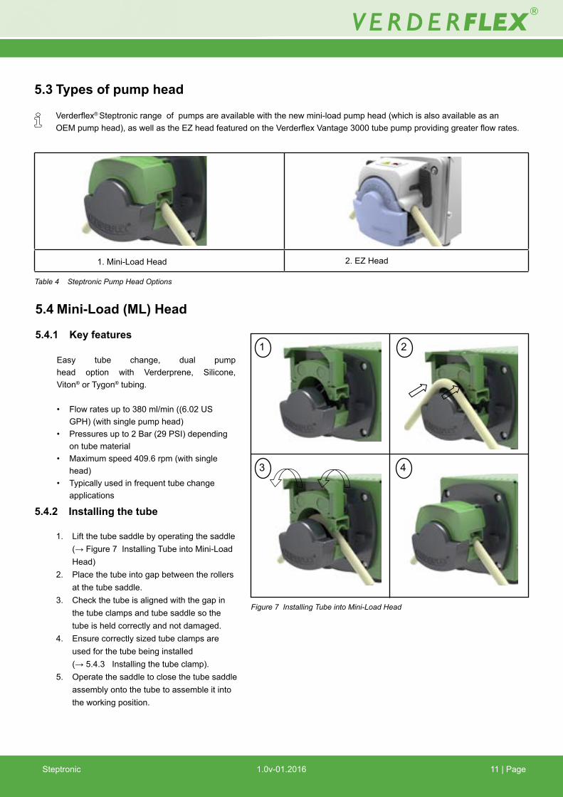
5.3 Types of pump head
Verderflex® Steptronic range of pumps are available with the new mini-load pump head (which is also available as an OEM pump head), as well as the EZ head featured on the Verderflex Vantage 3000 tube pump providing greater flow rates.
Table 4 Steptronic Pump Head Options
1. Mini-Load Head 2. EZ Head
5.4.2 Installing the tube
1. Lift the tube saddle by operating the saddle (→ Figure 7 Installing Tube into Mini-Load Head)
2. Place the tube into gap between the rollers at the tube saddle.
3. Check the tube is aligned with the gap in the tube clamps and tube saddle so the tube is held correctly and not damaged.
4. Ensure correctly sized tube clamps are used for the tube being installed
(→ 5.4.3 Installing the tube clamp). 5. Operate the saddle to close the tube saddle
assembly onto the tube to assemble it into the working position.
Figure 7 Installing Tube into Mini-Load Head
5.4 Mini-Load (ML) Head
5.4.1 Key features
Easy tube change, dual pump head option with Verderprene, Silicone, Viton® or Tygon® tubing.
• Flow rates up to 380 ml/min ((6.02 US GPH) (with single pump head) • Pressures up to 2 Bar (29 PSI) depending on tube material • Maximum speed 409.6 rpm (with single head) • Typically used in frequent tube change applications
1 2
3 4

Steptronic 1.0v-01.2016 12 | Page
5.4.3 Installing the tube clamp The tube clamps for the Mini-Load are a fixed
size design, for each of the 4 tube sizes it is designed to operate with.
To insert the tube clamps:
1. Raise the tube saddle by operating the saddle.
2. Offer the tube clamp horizontal to the pump main body (→ Figure 8 Installing Tube Clamp for Mini-Load Head) note the spig-ots to each side of the tube clamp, they are designed to fit in two grooves in the pump head main body.
3. Rotate the tube clamp slide down with the two spigots located in the grooves, until a click is heard as the tube clamp locates in the slot.
Figure 8 Installing the Tube Clamp for Mini-Load Head
5.4.4 Changing the tube clamp
To change the tube clamps:
1. Gently insert a small flat blade screw driver (max size 5mm) into the gap at the base of the tube clamp.
2. Rotate the screwdriver to overcome the slot.
3. Ensure the tube is aligned with the gap in the tube clamps and tube saddle so the tube is held correctly and not damaged.
4. Remove the tube clamp, by lifting and ro-tating in the clamp on each side.
Figure 9 Changing the Tube Clamp for Mini-Load Head
1 2
3 4
1 2
3 4

Steptronic 1.0v-01.2016 13 | Page
5.4.5 Replacing the pump head
1. Remove the pump head by pressing location lever and twisting pump head counter clock-wise 45°.
2. Offer the new pump head to the back plate at an angle locating the motor shaft to the ro-tor shaft within the pump head backplate at approx 45° to vertical, locating the lugs in the housing.
3. Push and twist until location lever clicks into position.
3. Remove by depressing location lever and twisting pump head counter clockwise 45°.
Figure 10 Replacing the Mini-Load Head5.4.6 Installing a Stackable ML-pump head
Installing a stackable ML pump head is very simi-lar to the procedure of fixing a standard pump head.
Note: The two pump heads of a stacked assem-
bly will be factory assembled and configured as such.
1. Before assembling, please observe slot in the end of the “rear” stack head assembly and the pin front assembly drive shaft (see enlarged view 3, 4 in fig.11).
2. Align the pin and slot, offer pump head to bac plate at an angle locating motor shaft and rotor shaft with pump head at approxi-mately 45° to vertical, locating back plate lugs in housing.
3. Push and twist until location lever clicks into position.
4. Remove by pressing location lever and twist-ing pump head counter clockwise 45°.
Figure 11 Installing a Stackable ML Pump Head
1 2
3 4
1 2
3 4
Drive Slot

Steptronic 1.0v-01.2016 14 | Page
5.5 EZ head
5.5.1 Key features
Easy tube change system, stackable multi head options with Verderprene, Silicone, Viton® or Tygon® tubing.
• Flow rates up to 1,310 ml/min (20.8 US GPH) (with single pump head) • Pressures up to 2 Bar (29 PSI) depending on tube material • Maximum speed 250rpm (with single pump head) • Typically used in frequent tube change applications
5.5.2 Installing the tube
1. Flip the lugs on both sides of the pump head to lift the top section
2. Once the head is lifted as shown in figure, insert the tube over the rollers.
3. Flip the lugs on both sides of the pump head to lock the top section down.
- Adjust the tube clamp to hold the tube in place and avoid slip
- Adjust the tube clamp on both sides of the pump head to the tube diameter.
- If a tube slip is observed, tighten the tension on the clamps
- Alternately, if a reduced flow is observed, reduce the clamp tension.
Figure 12 Installing the tube into EZ head
1 2
3 4
5 6
Figure 13 Replacing the EZ head
5.5.3 Replacing the pump head
1. Offer pump head to backplate at angle locating drive shaft and rotor shaft with pump head at approx 45° to vertical, locating backplate lugs in housing.
2. Push and twist until location lever clicks into position.
3. Remove by depressing location lever and twisting pump head counter clockwise 45°.
Location lugs
1 2
3 4
Steptronic 1.0v-01.2016
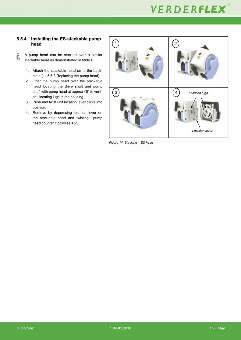
5.5.4 Installing the ES-stackable pump head
A pump head can be stacked over a similar stackable head as demonstrated in table 6.
1. Attach the stackable head on to the back-plate (→ 5.5.3 Replacing the pump head)
2. Offer the pump head over the stackable head locating the drive shaft and pump shaft with pump head at approx 45° to verti-cal, locating lugs in the housing.
3. Push and twist unit location lever clicks into position.
4. Remove by deperssing location lever on the stackable head and twisting pump head counter clockwise 45°.
Location lugs
Location lever
1 2
3 4
Figure 14 Stacking – ES head
15 | Page

Steptronic 1.0v-01.2016 16 | Page
5.6 Electrical connection
NOTEPump cannot be operated before wiring the D-25 pins connector Pump cannot be operated before wiring the D-25 cable as per wiring diagram in (→ Figure 18). The pump should be connected to external 0-10V or 4-20 mA control signal through the D-25 ribbon cable (for panel mounted versions) or the D-25 pins connector (for cased version) before operation.
5.6.1 Connecting to Control Signals
Table 5 Description - 25 WAY D-SUB PINs connector
PIN Description1234567
8910111213
PIN141516171819202122232425
DirectionStartStop0v Config inputsConfigure Maximum speedFlow scaling selectAnalogue select (switch between 0-10V or 4-20 mA)User function 0v0-10V IN0v AnalogueRemote power return (0v)0v External supply (earth)0v External supply (earth)
Speed decreaseFast primeSpeed IncreaseSelect Run / Config. modeConfigure Minimum speedConfigure RAMP speedHealthy / Fault indicator10V Analogue source4 - 20 mA INRemote power 12 - 36V12 - 36V dc External Supply12 - 36V dc External Supply
Description
Figure 15 Diagram - 25 WAY D-SUB PINs connector
5.6.2 Connecting Supply Voltage
The Steptronic Unit can be supplied with a voltage between 12V-36V D.C.
It is important to note that the unit has been optimised to use 24V D.C supply. Using a lower voltage will have an affect on unit output torque and may result in incorrect pump operation.
For application assistance, please contact your Verderflex representative.

Steptronic 1.0v-01.2016 17 | PageSteptronic 1.0v-05.2015
6. Remote Analogue ControlAn external Analogue/Digital control should be used to operate the Verderflex Steptronic range. Pump cannot be operated before wiring the D-25 pins connector.
6.1 Types of Analogue remote control:
0 - 10V D.C 4 – 20 mA
6.2 Layout of Back Plate
ModelAnalogue Control
0-10V d.c 4-20mA
Panel mount Mini-load
Panel mount EZ head
Cased 25 WAY D-SUB
Case 25 WAY D-SUB with HMI connection
Table 6 Models & Control features available
Figure 16 Backplate - Standard (withoutConfigurationport)
Figure 17 Backplate - With HMI (portforconfiguration)

Steptronic 1.0v-01.2016 18 | Page
7. Wiring the 25 WAY D-SUB connector7.1 Description of PINs: The PINs on the 25 WAY D-SUB connector can be grouped into:
1. Pump operation controls 2. Configuration PINs (for factory configuration) 3. Fault indicator 4. Power source 5. Remote external optional power source
7.2 User Controls Control features available with the Analogue 4-20mA / 0-10V are:
1. Start/ Run 2. Stop 3. Direction of rotation 4. Prime pump 5. Speed control 6. Healthy / Fault indicator
Note: It is possible to use isolated supplies for the 24V switching inputs. The Steptronic unit will have been pre-configured to allow for this if necessary.
Pin 23 and 11 provides external excitation to optical
isolation. If jumpers J9/J10 links are removed then a separate supply will need to be provided to use the 24V switching inputs. The board will also need a sepa-rate supply provided through PCB J1.
Pins 24 and 25 both provide positive power supply
from the board. Pins 12 and 13 both supply ground from the board.
Figure 18 Wiring Diagram - 25 WAY D-SUB Connector
Note: 1. Remote control power source can be selected by J9&J10
links. If the links are connected, then the remote control inputs and the fault output are controlled by the same power supply that is fed via PCB J1 or D-SUB 25 WAY pins 12/13 & 24/25 (local). If the J9/J10 links are removed, then a separate power source (12-36 Vdc) for the remote control inputs and fault output can be connected to 25W D-SUB pins 11 & 23 (Remote). Both J9 and J10 links must be connected or disconnected. Irreparable damage will occur if a remote source is used with the links engaged.
2. In Analogue speed control mode, A closed connection
between pins 4&7 permits speed control via 4-20mA cur-rent loop. Maximum safe current draw is 27mA. An open connection permits speed control via 0-10V. Maximum input must not exceed 13.0V.
3. Refer to product data plate for configured Speed settings of fixed speed digital control models.
4. Fault output is normally high when healthy and switches low when in fault. If ‘Remote Power source’ is used, (J9&J10 links removed) then connect one side of the indicator to the ‘+ Remote Power source (pin23)’ and the return side to pin 20. If ‘Local Power’ is used, (J9&J10 links connected) then connect one side of the indicator to ‘+ Local Power (Pin24/25)’ and the return side to pin 20.

Steptronic 1.0v-01.2016 19 | Page
7.2.1 Starting the pump
A volt-free connection between pins 2 and 8 will start the pump. The flow rate will be determined by the analogue speed control value (see Speed control section). The start signal operates as a Normally Open signal and removal of the start signal will stop the pump. When the start signal is removed, the pump will use the ramp to slow down.
7.2.2 Stopping the pump
A volt-free connection between pins 3 and 8 will stop the pump. The pump will stop regardless of the state of the START signal. To restart the pump after using the STOP signal, the START signal must be toggled.
7.2.3 Direction of rotation
A volt-free connection between pins 1 and 8 will change the di-rection of rotation of the pump. Pump direction will only change when the pump is stopped.
7.2.4 Prime Pump
A volt-free connection between pins 15 and 8 will accelerate the pump to the pre-set maximum speed. The pump will only respond to a PRIME signal when the pump is stopped.
7.2.5 Speed Control - 0 to 10 V
Pump speed can be modified by using a 0-10V signal between pins 9 and 10. If no 10V supply is available, pin 21 can be used to provide a 10V supply. Pin 10 must only be used for supplying 0V for analogue pins. Below is an example of 0-10V control with a 2.5K Ohm poten-tiometer.If using a supply voltage > 30V, the 10V supply rail will not func-tion correctly. The installer will need to source a suitable ex-ternal 10V feed to use analogue control with supply voltages > 30V.
7.2.6 Speed Control - 4 to 20 mA
Pump speed can be modified by using a 4-20mA signal be-tween pins 22 and 10. In order to use the 4-20mA connection, pins 4 and 7 need to be linked together.Maximum current draw is 27mA.
7.2.7 Healthy / Fault Indicator
This logical output is high (OFF) when the pump is healthy and logic low (ON) when in fault. The fault signal is grounded through pin 11.

Steptronic 1.0v-01.2016
7.3 Getting Started with 25 WAY D-SUB Connector If the user wishes to test the pump to verify operation, the
following steps should be taken:
1. Ensure jumpers J9/J10 are fitted. 2. Provide the board with a 24V supply through PCB J1.3. Supply a 0-10 Volt signal to pin 9 (0-10V in).4. Close the start signal as detailed above. 5. Pump will start spinning.
7.4 Factory Configuration of operat-ing parameters
To configure the variable parameters of Steptronic, a configura-tion display unit is required to set and view the parameter val-ues.Steptronic can be configured when the mode is switched from RUN to Configure: (Pin 17, 25w D-sub) When the configuration display is connected, the display will show:A) Stopped/ RunningB) Speed demand (RPM)C) Flow rate (mL/Min)
Only when the pump is stopped will switching this input low change the pump from Run to Configuration mode. The display will confirm this action by displaying (PROG).
7.4.1 Selection of Analogue mode:(Pin 7, 25w D-sub)
Switching this input logically low will change the Analogue speed control input from 0-10V to 4-20mA. Analogue speed control is only available when the pump is configured to Ana-logue speed control mode.
7.4.2 Maximum speed:
Switching this input low allows the Maximum speed setting of the pump to be configured. The display will show (MAX) and the current set maximum speed value in RPM.
Switch the User “Speed up” (Pin 16, 25w D-sub) or “Speed down” (Pin 14, 25w D-sub) inputs to change the value of Max speed.
The maximum value allowed is 409.6RPM and the minimum value of Max speed will always be at least 2RPM higher than the set Min speed value.
Switch the Max speed input back to logical high to record the set value and return the display back to (PROG).
7.4.3 Minimum speed:
Switching this input low allows the Minimum speed setting of the pump to be configured. The display will show (MIN) and the current set minimum speed value in RPM.
Switch the User “Speed up” (Pin 16, 25w D-sub) or “Speed down” (Pin 14, 25w D-sub) inputs to change the value of Min speed.
The minimum value allowed is 0.000RPM and the maximum value of Min speed will always be at least 2RPM lower than the set Max speed value.
Switch the Min speed input back to logical high to record the set value and return the display back to (PROG).
7.4.4 Flow(Pin 6, 25w D-sub)
Switching this input low allows the Flow rate of the display to be calibrated to show a flow rate that is relative and synchronous with the pump speed. The display will show (FLOW) + XXX.XmL/Min + “The set speed” (RPM).
Assuming that calibration has been measured at the set RPM, the flow-rate can now be changed to match the measured val-ue.
To change the set value: - Switch the User “Speed up” (Pin 16, 25w D-sub) or “Speed down” (Pin 14, 25w D-sub) inputs to change the value of flow.
Switch the Flow input back to logical high to record the set val-ue and return the display back to (PROG).
The displayed flow-rate will now be relative and synchro-nous with changes in RPM.
7.4.5 Ramp(Pin 19, 25w D-sub)
Switching this input low allows the pumps acceleration / de-celeration value to be set.The display will show (RAMP) + X seconds. Acceleration and decelerations values are identical and cannot be separated.
The minimum value of Ramp is 1 second.The maximum value of Ramp is 5 seconds.Ramp rate value is relative to the entire span range of the pump (0.000RPM – 409.6RPM).
If the span range is reduced, then the Ramp timing is also re-duced accordingly.
To change the set value: - Switch the User “Speed up” (Pin 16, 25w D-sub) or “Speed down” (Pin 14, 25w D-sub) inputs to change the value of ramp.Switch the “Ramp” input back to logical high to record the set value and return the display back to (PROG).
7.4.6 Logical low:
Is the connection of a configuration input to an internal digital zero volts DC (Pin 4, 25w D-sub). This point of connection must be used to switch all configuration inputs.
7.4.7 Error displayed:
If more than one configuration input has been accidently se-lected the display will report “ERROR” to demonstrate the fact. Find and remove the erroneous input to restore normal opera-tion.
For example: Config (prog) + Flow + Ramp= ERROR.
20 | Page

Steptronic 1.0v-01.2016 21 | Page
8 Inspection, Maintenance and Repairs
8.1 Inspections The inspection intervals depend on the pump operating cycle.
1. Check at appropriate intervals: – Normal operating conditions unchanged
2. For trouble-free operation, always ensure the following: – No leaks – No unusual running noises or vibrations – Tube in position
8.2 Maintenance
These pumps are generally maintenance free and any work should normally be limited to inspections; these may be more frequent in dust and/or hot condition.
Pump motor is lubricated for life and should not require attention. Rotor rollers are self-lubricated. Pump tubing will not last forever; establish suitable tube replacement schedule to prevent inconvenient tube failure.
The pump casing in the cased steptronic version contains no user serviceable parts and is factory sealed to confirm integrity. Pump warranty will be invalidated if the seal is broken.
Risk of injury due to running pump or hot parts! Do not carry out any repair/maintenance work on a pump in operation. Allow the pump to cool down completely before starting any repair work.
Risk of electrocution! Have all electrical work carried out only by qualified electricians.
8.2.1 Cleaning the pump
High water pressure or spray water can damage motors! Do not clean motors with water 1. Clean large-scale grime from the pump head. 2. Rinse the tube carefully to remove chemicals
DANGER
DANGER
NOTE

Steptronic 1.0v-01.2016 22 | PageSteptronic
8.2.2 Maintenance schedule
Table 7 Maintenance schedule
Task Frequency Action
Check pump for leaks and damage
Check pump for unusual temperatures or noise in operation
Replace tube element
Check pump housing and rotor internally
– Before pump start up – Daily visual inspection – Scheduled intervals during operation
– Daily visual inspection – Scheduled intervals during operation
– After inspection when required– When flow has dropped by 25% of original value– When the tube is burst/damaged
– Annually– On replacing the tube
Repair leaks and damage before operating the pump Replace components as necessary. Clean up any spillage.
Check pump and motor for damage. Replace worn components.
Replace tube (→ 5.4.2 & 5.5.2)
Worn and damaged surfaces give rise to premature tube failure Replace worn components. Check bearing play and function.

Steptronic 1.0v-01.2016
8.3.3 Rebuild / Repair
Reinstall the components, in accordance with the marks applied.
Material damage due to unsuitable components! Always replace lost or damaged parts with genuine Verderflex spares.
1. Observe the following during the installation: – Replace worn parts with genuine spare parts.2. Clean all parts.3. Reassemble the pump (→ refer sectional drawing).4. Install the pump in the system (→ 5 Installation and connection)
8.4 Ordering spare parts
For trouble-free replacement in the event of faults, we recommend keeping spare parts available on site.
The following information is mandatory when ordering spare parts (→ Name plate ): – Pump model – Year of manufacture – Part number / Description of part required – Serial number – Quantity
8.3 Repairs
Risk of death due to electric shock! Have all electrical work carried out by qualified electrician only
8.3.1 Preparations for dismounting Pump completely emptied, flushed and decontaminated Electrical connections disconnected Pump cooled down Auxiliary systems shut down, depressurized and emptied
Risk of injury while removing the pump components! Use protective equipment when carrying out any work on the pump. Observe manufacturer’s instructions (e.g. for Motor...)
8.3.2 Returning the pump to the manufacturer Completely emptied and decontaminated. Pump cooled down Tube removed (→ 5.4.2 & 5.5.2)
Obtain prior authorisation before repair or return of the pump. Enclose a completed document of compliance when returning pumps or components to the manufacturer
23 | Page
...at the customer’s premises
...at the manufacturer’s premises
...at the manufacturer’s premises for warranty repairs
– Return the defective component to the manufacturer.– Decontaminate if necessary.
– Flush the pump and decontaminate it if it was used for hazardous pumped liquids.
– Only in the event of hazardous pumped liquid, flush and decontaminate the pump
Table 8 Measures for return
Repairs Measure for return
DANGER
NOTE
WARNING

Steptronic 1.0v-01.2016 24 | Page
9. Storing pumps and tubes We recommend certain pre-storage actions and
precautions be taken whilst pumps and their components are not in use.
Similarly, tubes and spares may be held in stock
to service working pumps and their recommended storage conditions are advised.
9.1 Pre-Storage Actions – The tube should be removed from the pump
– The pump casing should be washed out allowed to dry and any external build up of product removed.
9.2 Storage Conditions– Pumps should be stored in a dry environment, out of
direct sunlight. Depending on these conditions, it may be advisable to place a moisture absorbing product, such as Silica gel, inside the pump’s casing whilst the pump is stored.
– Tubes should be stored as supplied in their wrapper and should be stored away from direct sunlight and at room temperature.

Steptronic 1.0v-01.2016 25 | Page
10. Troubleshooting 10.1 Pump malfunctions
If malfunctions occur which are not specified in the following table or cannot be traced back to the specified causes, please consult the manufacturer.
Possible malfunctions are identified and respective cause and remedy are listed in the table.
CauseProblem Solution
Ratio of inner diameter / wall thickness too large for the application (tube too ‘soft’)
Viscosity too high
Suction lift too high, resulting in tube not fully returning to fully round
Wall thickness does not match the specifications of the tube clamp used.
Discharge pressure too high
Using non-standard tubing
Tube outer diameter too small for the pump head used
Low Flow / low discharge pressure
Tube walks through pump head
Use thicker wall thickness tube with the same inner diameter. This may require a differ-ent tube clamp or pump
Run Pump slower with larger inner diameter tube
Run the pump slower
Use thicker wall thickness tube with the same inner diameter. This may require a different tube clamp or pump.
Use a bigger pump running slower
Purchase appropriate tube clamp or change wall thickness
Poor flow is caused by excessive backflow, reduce discharge pressure
Use Verderflex approved genuine tubing
Adjust tube clamp tension / check tube clamp installed
Use tube with correct outer diameter.
Table 9 Pump troubleshooting list

Steptronic 1.0v-01.2016 26 | Page
11. Appendix11.1 Technical Specifications
11.1.1 Pump Specifications
Table10PumpSpecifications–[email protected]
11.1.2 Ambient conditions Operation under any other ambient condition would require approval from the manufacturer
Operating conditions • Ambient temperature –5 °C to +45 °C • Up to 30°C: 80% RH (Non condensing). 30°C - 45°C reducing linearly to 30% RH (Non condensing)• Setup height above sea level ≤ 1000m / 3000 ft above sea level
Storage conditions • Ambient temperature +18 °C to +65 °C • Relative humidity – long—term ≤ 80 %
Maximum Motor Temperature Rise: 80°C
11.1.3 Power SupplyMotor supply operating voltage range:• Minimum 12V DC*
* Minimumof12VcanonlybeusedinsingleheadconfigurationsforMini-loadhead.
Minimumof12VnotsuitableforEZhead.
• Nominal 24V DC• Maximum 36V DC
Control circuit operating voltage range• Minimum 12V DC• Maximum 36V DC
Drive Power supply:• 40VA (SMPS)• 35VA Linear
11.1.4 Tube Variants For safety reasons we do not recommend pumping liquids greater than 80°C (176°F). The following criteria are important when selecting a tube:• Chemical resistance• Food grade quality• Tube life• Physical compatibility
Table11VerderflexTubevariants
Size Value Max. delivery pressure
IP RatingStandard Cased Version:Open Frame Version:Optional IP66 Casing: Max. configurable speedMin. configurable speed Dimensions
Typical audible noise level (No pump head)
2 bar
IP31IP00IP66
409.6 rpm0 rpm Refer datasheet for models
50dBA@1meter
Type Feature
Verderprene
Silicone
Tygon
Viton
General purpose tubing
High sterility tubing
Chemical fluids tubing
Aggressive chemical tubing

Steptronic 1.0v-01.2016 27 | Page
12 List of Figures and Tables 12.1 List of figures
Figure 1 Name plate 3.2
Figure 2 Layout – Steptronic Mini-Load Cased Version 3.4
Figure 3 Layout – Steptronic EZ head Cased Version 3.5
Figure 4 Layout – Steptronic Mini-Load Panel Mounted 3.6
Figure 5 Layout – Steptronic EZ head Panel Mounted 3.7
Figure 6 Mounting Panel - Dimensional Details 3.8
Figure 7 Installing the Tube into Mini-Load Head 5.4.2
Figure 8 Installing the Tube Clamp for Mini-Load Head 5.4.3
Figure 9 Changing the Tube Clamp for Mini-Load Head 5.4.4
Figure 10 Replacing the Mini-Load Head 5.4.5
Figure 11 Installing a stackable ML pump head 5.4.6
Figure 12 Installing the Tube into EZ head 5.5.2
Figure 13 Replacing the EZ head 5.5.3
Figure 14 Stacking ES-head 5.5.4
Figure 15 Diagram - 25 WAY D-SUB PINs connector 5.6.1
Figure 16 Backplate - Standard (without configuration port) 6.2
Figure 17 Backplate - with HMI (port for configuration) 6.2
Figure 18 Wiring Diagram - 25 WAY D-SUB connector 8.0
12.2 List of tables
Table 1 Target groups and their duties 1.1
Table 2 Warnings and consequences
of disregarding them 1.2
Table 3 Symbols and their meaning 1.2
Table 4 Steptronic Pump Head Options 5.3
Table 5 Description - 25WAY D-SUB PINs connector 5.6.1
Table 6 Models and control features available 6.2
Table 7 Maintenance schedule 8.2.2
Table 8 Measures for return 8.3.2
Table 9 Pump troubleshooting list 10.1
Table 10 Pumps specifications - Steptronic @ 24V D.C Supply 11.1.1
Table 11 Verdeflex Tube variants 11.1.4
Table 12 Declaration of conformity according
to EC Machine Directive 13

Steptronic 1.0v-01.2016 28 | Page
13 Declaration of conformity according to EC Machine Directive
EC declaration of conformity according to machine directive, appendix II A We, VERDER Ltd., Unit 3 California Drive, Castleford hereby declare that the following machine adheres to the relevant EC directives detailed below
Designation Verderflex Steptronic
EC directives: • Machine Directive (2006/42/EC) • Low-voltage directive (2006/95/EC) • EMC directive (2004/108/EC)
Responsible for the documentation
Date: 01/ 01/ 2016
VERDER Ltd. Unit 3 California Drive Castleford WF10 5QH UK
Company stamp / signature:
David SampsonHead of Development/Construction
Company stamp / signature:
David HoylandHead of Quality
Table 12 Declaration of conformity according to EC Machine Directive