perkins 3000 series · 2015. 1. 15. · perkins 3000 series user’s handbook 3012/cv12 12 cylinder...
TRANSCRIPT

1
Perkins 3000 Series
USER’S HANDBOOK
3012/CV12 12 cylinder diesel engines for industrial applications
The contents of this handbook are applicable to both CV12 and 3000 Series - 3012 engines.
Publication TSD 3138 (issue 13)©Proprietary information of Perkins Group Limited, all rights reservedThe information is correct at the time of print.Published in May 2001 by Technical Publications,Perkins Engines Company Limited, Lancaster Road,Shrewsbury, Shropshire SY1 3NX, England
This document has been printed from SPI². Not for Resale

2
This document has been printed from SPI². Not for Resale

3
Contents
1 General informationIntroduction . . . . . . . . . . . . . . . . . . . . . . . . . . . . . . . . . . . . . . . . . . . . . . . . . . . . . . . . . . . . 5How to care for your engine . . . . . . . . . . . . . . . . . . . . . . . . . . . . . . . . . . . . . . . . . . . . . . . 5Engine identification . . . . . . . . . . . . . . . . . . . . . . . . . . . . . . . . . . . . . . . . . . . . . . . . . . . . . 6Perkins companies . . . . . . . . . . . . . . . . . . . . . . . . . . . . . . . . . . . . . . . . . . . . . . . . . . . . . . 7Safety precautions . . . . . . . . . . . . . . . . . . . . . . . . . . . . . . . . . . . . . . . . . . . . . . . . . . . . . . 8
2 Engine viewsIntroduction . . . . . . . . . . . . . . . . . . . . . . . . . . . . . . . . . . . . . . . . . . . . . . . . . . . . . . . . . . . . 9Location of engine parts . . . . . . . . . . . . . . . . . . . . . . . . . . . . . . . . . . . . . . . . . . . . . . . . . . 9
3 Operation instructionsPreparations for a new or an overhauled engine . . . . . . . . . . . . . . . . . . . . . . . . . . . . . . 11How to start a new or overhauled engine or an engine which has been in storage . . . . 12Normal start procedures . . . . . . . . . . . . . . . . . . . . . . . . . . . . . . . . . . . . . . . . . . . . . . . . . 13How to start the engine in low ambient temperatures . . . . . . . . . . . . . . . . . . . . . . . . . . . 13Precautions . . . . . . . . . . . . . . . . . . . . . . . . . . . . . . . . . . . . . . . . . . . . . . . . . . . . . . . . . . . 13How to stop the engine . . . . . . . . . . . . . . . . . . . . . . . . . . . . . . . . . . . . . . . . . . . . . . . . . . 13
4 Preventive maintenancePreventive maintenance periods . . . . . . . . . . . . . . . . . . . . . . . . . . . . . . . . . . . . . . . . . . . 15Schedule for engines in normal use . . . . . . . . . . . . . . . . . . . . . . . . . . . . . . . . . . . . . . . . 16Schedule for engines in intermittent use . . . . . . . . . . . . . . . . . . . . . . . . . . . . . . . . . . . . . 17Coolant level . . . . . . . . . . . . . . . . . . . . . . . . . . . . . . . . . . . . . . . . . . . . . . . . . . . . . . . . . . 18Lubricating oil level . . . . . . . . . . . . . . . . . . . . . . . . . . . . . . . . . . . . . . . . . . . . . . . . . . . . . 18Restriction indicator . . . . . . . . . . . . . . . . . . . . . . . . . . . . . . . . . . . . . . . . . . . . . . . . . . . . 19How to renew the elements of the air filters . . . . . . . . . . . . . . . . . . . . . . . . . . . . . . . . . . 19How to drain the primary fuel filter . . . . . . . . . . . . . . . . . . . . . . . . . . . . . . . . . . . . . . . . . 19How to check the drive belts . . . . . . . . . . . . . . . . . . . . . . . . . . . . . . . . . . . . . . . . . . . . . . 20How to renew the fan belts . . . . . . . . . . . . . . . . . . . . . . . . . . . . . . . . . . . . . . . . . . . . . . . 20How to renew the alternator belt . . . . . . . . . . . . . . . . . . . . . . . . . . . . . . . . . . . . . . . . . . . 20How to check the specific gravity of the coolant . . . . . . . . . . . . . . . . . . . . . . . . . . . . . . . 21How to check the pH value of the coolant . . . . . . . . . . . . . . . . . . . . . . . . . . . . . . . . . . . . 21How to renew the engine lubricating oil . . . . . . . . . . . . . . . . . . . . . . . . . . . . . . . . . . . . . 22How to renew the canisters of the oil filter . . . . . . . . . . . . . . . . . . . . . . . . . . . . . . . . . . . 22
Continued
This document has been printed from SPI². Not for Resale

4
How to clean the primary fuel filter . . . . . . . . . . . . . . . . . . . . . . . . . . . . . . . . . . . . . . . . . 23How to renew the canister of the main fuel filter . . . . . . . . . . . . . . . . . . . . . . . . . . . . . . . 23How to check/adjust the timing of the fuel injection pump . . . . . . . . . . . . . . . . . . . . . . . . 24Fuel injector fault . . . . . . . . . . . . . . . . . . . . . . . . . . . . . . . . . . . . . . . . . . . . . . . . . . . . . . . 25How to remove the fuel injectors . . . . . . . . . . . . . . . . . . . . . . . . . . . . . . . . . . . . . . . . . . . 25How to correct the fuel injector sleeves . . . . . . . . . . . . . . . . . . . . . . . . . . . . . . . . . . . . . . 25How to fit the fuel injectors . . . . . . . . . . . . . . . . . . . . . . . . . . . . . . . . . . . . . . . . . . . . . . . 25How to eliminate air from the fuel system . . . . . . . . . . . . . . . . . . . . . . . . . . . . . . . . . . . . 27How to check the tappet clearances . . . . . . . . . . . . . . . . . . . . . . . . . . . . . . . . . . . . . . . . 28Turbochargers . . . . . . . . . . . . . . . . . . . . . . . . . . . . . . . . . . . . . . . . . . . . . . . . . . . . . . . . . 29Alternator . . . . . . . . . . . . . . . . . . . . . . . . . . . . . . . . . . . . . . . . . . . . . . . . . . . . . . . . . . . . . 29How to drain the coolant system . . . . . . . . . . . . . . . . . . . . . . . . . . . . . . . . . . . . . . . . . . . 29How to clean the coolant system . . . . . . . . . . . . . . . . . . . . . . . . . . . . . . . . . . . . . . . . . . . 29How to fill the coolant system . . . . . . . . . . . . . . . . . . . . . . . . . . . . . . . . . . . . . . . . . . . . . 29
5 Engine fluidsDiesel fuel . . . . . . . . . . . . . . . . . . . . . . . . . . . . . . . . . . . . . . . . . . . . . . . . . . . . . . . . . . . . 31Coolant . . . . . . . . . . . . . . . . . . . . . . . . . . . . . . . . . . . . . . . . . . . . . . . . . . . . . . . . . . . . . . 31Lubricating oil . . . . . . . . . . . . . . . . . . . . . . . . . . . . . . . . . . . . . . . . . . . . . . . . . . . . . . . . . 32Recommended oils for Europe . . . . . . . . . . . . . . . . . . . . . . . . . . . . . . . . . . . . . . . . . . . . 33Recommended oils for remainder of the world . . . . . . . . . . . . . . . . . . . . . . . . . . . . . . . . 34Warranty . . . . . . . . . . . . . . . . . . . . . . . . . . . . . . . . . . . . . . . . . . . . . . . . . . . . . . . . . . . . . 34
6 Fault diagnosisProblems and possible causes . . . . . . . . . . . . . . . . . . . . . . . . . . . . . . . . . . . . . . . . . . . . 36Code list of possible causes . . . . . . . . . . . . . . . . . . . . . . . . . . . . . . . . . . . . . . . . . . . . . . 37
7 Engine preservationIntroduction . . . . . . . . . . . . . . . . . . . . . . . . . . . . . . . . . . . . . . . . . . . . . . . . . . . . . . . . . . . 39Short period storage . . . . . . . . . . . . . . . . . . . . . . . . . . . . . . . . . . . . . . . . . . . . . . . . . . . . 39Long period storage . . . . . . . . . . . . . . . . . . . . . . . . . . . . . . . . . . . . . . . . . . . . . . . . . . . . . 39Removal from storage . . . . . . . . . . . . . . . . . . . . . . . . . . . . . . . . . . . . . . . . . . . . . . . . . . . 40Approved products for engine preservation . . . . . . . . . . . . . . . . . . . . . . . . . . . . . . . . . . . 41
8 Parts and ServiceIntroduction . . . . . . . . . . . . . . . . . . . . . . . . . . . . . . . . . . . . . . . . . . . . . . . . . . . . . . . . . . . 43Service literature . . . . . . . . . . . . . . . . . . . . . . . . . . . . . . . . . . . . . . . . . . . . . . . . . . . . . . . 43Training . . . . . . . . . . . . . . . . . . . . . . . . . . . . . . . . . . . . . . . . . . . . . . . . . . . . . . . . . . . . . . 43Service Bulletins . . . . . . . . . . . . . . . . . . . . . . . . . . . . . . . . . . . . . . . . . . . . . . . . . . . . . . . 43
9 Engine data3012 diesel engine . . . . . . . . . . . . . . . . . . . . . . . . . . . . . . . . . . . . . . . . . . . . . . . . . . . . . 45
This document has been printed from SPI². Not for Resale

5
1General information 1
Introduction
The 3012 heavy duty diesel engine is the latest development from Perkins Engines Company Limited, a world leader in the design and manufacture of high performance diesel engines.
More than fifty years of diesel production experience, together with the use of the latest technology, have been used in the manufacture of your engine to give you reliable and economic power.
To ensure that you use the correct information for your specific engine type, refer to ‘Engine identification’ on page 6.
Danger is indicated in the text by two methods:
Warning! This indicates that there is a possible danger to the person.
Caution: This indicates that there is a possible danger to the engine.
Note: Is used where the information is important, but there is not a danger.
How to care for your engine
This handbook has been written to assist you to maintain and operate your engine correctly.
To obtain the best performance and the longest life from your engine, you must ensure that the maintenance operations are done at the intervals shown in ‘Preventive maintenance’. If the engine is operated in a very dusty environment or other adverse conditions, certain maintenance intervals will have to be reduced. Renew the filter elements and the lubricating oil regularly to ensure that the inside of your engine remains clean.
Ensure that all adjustments and repairs are done by personnel who have had the correct training. Perkins distributors have this type of personnel available. You can also obtain parts and service from your Perkins distributor. If you do not know the address of your nearest distributor, enquire at one of the Perkins companies listed on page 7.
The left and right sides of the engine are as seen from the rear (flywheel) end. Where reference is made to ‘A’ and ‘B’ banks of cylinders: ‘A’ bank is to the right and ‘B’ bank is to the left when viewed from the rear end.
Read the ‘Safety precautions’ and remember them. They are given for your protection and must be applied at all times.
This document has been printed from SPI². Not for Resale
1
6
Engine identification
If you need parts, service or information for your engine, you must give the complete engine number to your Perkins distributor.
The engine number is stamped on the data plate which is fastened to the left side of the crankcase.
For early engines, a typical engine number is: 6A27487U 59426U, which consists of these codes:
6A = Engine family27487 = Engine numberU = Country of manufacture59426 = Build line numberU = Year of manufacture
Engines made after August 1994, have a new engine number system. For these engines, a typical number is: SGJ 12 0029 U 3254 C, which consists of these codes:
SG = Engine applicationJ = Engine type12 = Number of engine cylinders0029 = Engine specification numberU = Country of manufacture3254 = Build line numberC = Year of manufacture
Units such as the fuel injection pump and turbochargers have their own data plates.
This document has been printed from SPI². Not for Resale
1
7
Perkins companies
Australia
Perkins Engines Australia Pty. Limited,Suite 4, 13A Main Street,Mornington, Victoria 3931, Australia.Telephone: 0061 (0)597 51877Telex: Perkoil AA 30816Fax: 0061 (0)597 1305
China
Perkins Engines (Tianjin) Limited,Jinwei Road,Beichen District, Tianjin,300402ChinaTelephone: (86) (22) 2699 2288Fax: (86) (22) 2699 3784
France
Perkins France SAS,"Parc des reflets",165 Avenue du Bois de la Pie,95700 Roissy Charles de Gaulle, France.Telephone: 0033 (01) 49-90-7171Fax: 0033 (01) 49-90-7190
Germany
Perkins Motoren G.m.b.H.,Saalaeckerstrasse 4,63801 Kleinostheim,Germany.Telephone: 0049 6027 5010Fax: 0049 6027 501124
Italy
Motori Perkins S.p.A.,Via Socrate 822070 Casnate con Bernate (Como), Italy.Telephone: 0039 (0)31 564625/564633Fax: 0039 (0)31 565480/564145/396001
Japan
Perkins Engines, Inc. Japan Branch,8 Fl, 2-2-19 Akasaka, Minato-ku,Tokyo 107-0052, Japan.Telephone: 0081 (0)3 3560 3877Fax: 0081 (0)3 3560 3878
Korea
Perkins Engines (Korea)Textile Center 12FDaechi 3 dong 944-31Kangnam-KuSeoul, 135-283KoreaTelephone: (822) 528 3377Fax: (822) 528 3378
Singapore
Perkins Engines (Asia Pacific) Pte. Limited,20 Harbour Drive,#07-06A, PSA Vista,Singapore 117612.Telephone: (65) 874 7712Fax: (65) 874 7722
United Kingdom
Perkins Engines Company Limited,Lancaster Road, Shrewsbury, SY1 3NX,England.Telephone: 0044 (0)1743 212000Telex: 35171 PESL GFax: 0044 (0)1743 212700
United States of America
Perkins Engines - North America12025, Tech Center DriveLivoniaMichigan 48150USATelephone: 001 313 266 5427Fax: 001 313 266 2700
Perkins Engines Latin America Inc,Suite 620,999, Ponce de Leon Boulevard,Coral Gables,Florida 33134,USA.Telephone: 001 305 442 7413Telex: 32501 Perken GFax: 001 305 442 7419
In addition to the above companies, there are Perkins distributors in most countries. Perkins Engines Company Limited, Shrewsbury or one of the above companies can provide details.
This document has been printed from SPI². Not for Resale

1
8
Safety precautions
These safety precautions are important.
Reference must also be made to the local regulations in the country of operation.
l Only use these engines in the type of application for which they have been designed.
l Do not change the specification of the engine.
l Do not smoke when you put fuel in the tank.
l Clean away fuel which has been spilt. Material which has been contaminated by fuel must be moved to a safe place.
l Do not put fuel in the tank while the engine runs (unless it is absolutely necessary).
l Do not clean, add lubricating oil, or adjust the engine while it runs (unless you have had the correct training; even then extreme caution must be used to prevent injury).
l Do not make adjustments that you do not understand.
l Ensure that the engine does not run in a location where it can cause a concentration of toxic emissions.
l Other persons must be kept at a safe distance while the engine or equipment is in operation.
l Do not permit loose clothing or long hair near moving parts.
l Keep away from moving parts during engine operation. Warning! Some moving parts cannot be seen clearly while the engine runs.
l Do not operate the engine if a safety guard has been removed.
l Do not remove the filler cap of the cooling system while the engine is hot and while the coolant is under pressure, because dangerous hot coolant can be discharged.
l Do not use salt water or any other coolant which can cause corrosion in the closed coolant circuit.
l Do not allow sparks or fire near the batteries (especially when the batteries are on charge) because the gases from the electrolyte are highly flammable. The battery fluid is dangerous to the skin and especially to the eyes.
l Disconnect the battery terminals before a repair is made to the electrical system.
l Only one person must control the engine.
l Ensure that the engine is operated only from the control panel or from the operator’s position.
l If your skin comes into contact with high-pressure fuel, obtain medical assistance immediately.
l Diesel fuel and lubricating oil (especially used lubricating oil) can damage the skin of certain persons. Protect your hands with gloves or a special solution to protect the skin.
l Do not wear clothing which is contaminated by lubricating oil. Do not put material which is contaminated with oil into the pockets.
l Discard used lubricating oil in a safe place to prevent contamination.
l Ensure that the control lever of the transmission drive is in the ‘out-of-drive’ position before the engine is started.
l The combustible material of some components of the engine (for example certain seals) can become extremely dangerous if it is burned. Never allow this burnt material to come into contact with the skin or with the eyes.
l Fuel and oil pipes MUST be inspected for cracks or damage before they are fitted to the engine.
l Fit only genuine Perkins parts.
This document has been printed from SPI². Not for Resale

9
2Engine views 2
Introduction
Perkins engines are built for specific applications and the views which follow do not necessarily match your engine specification.
Location of engine parts
Front and left side view of the 3012 engine
1 ‘B’ bank air cleaner
2 ‘B’ bank turbocharger
3 Exhaust manifold
4 Coolant pump
5 Canisters of the lubricating oil filter
6 Crankcase breather
7 Fan
8 Thermostat housings
A 482
1
2
65
4
3
8
7
This document has been printed from SPI². Not for Resale

2
10
Rear and right side view of the 3012 engine
B 483
1
6 5
4
3
9
8
7
10
2
1 ‘A’ bank turbocharger
2 Alternator
3 Dipstick
4 Filler cap for lubricating oil
5 Lubricating oil sump
6 Starter motor
7 Flywheel housing
8 Flywheel
9 Canisters of the fuel filter
10 ‘A’ bank air cleaner
This document has been printed from SPI². Not for Resale
11
3Operation instructions 3
Preparations for a new or an overhauled engine
Every new engine supplied by Perkins Engines Company Limited, Shrewsbury, is run-in before it leaves the factory.
1 Check that all protection covers and blanking plugs have been removed.
2 Fit all components that were removed for storage or for transport.
3 Ensure that drain plugs for coolant and for lubricating oil are securely fitted.
4 Where necessary, connect the remote control linkages, the pressure gauge pipes, the air inlet pipes and the wiring loom.
5 Connect the fuel pipes.
6 Connect the exhaust pipes.
7 Fill the fuel tank(s) with the correct grade of fuel (see page 31).
8 Fill the cooling system with the approved coolant mixture (see page 31).
9 Fill the sump to the H mark on the dipstick with the correct grade of lubricating oil (see page 32).
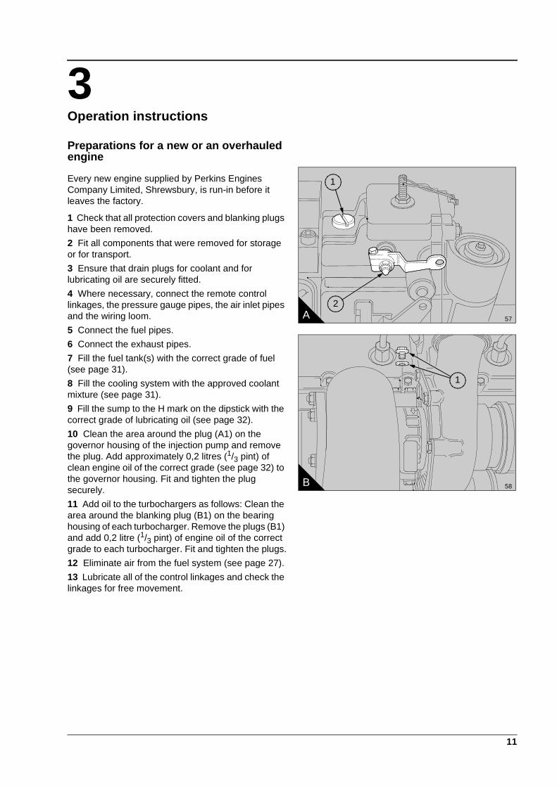
10 Clean the area around the plug (A1) on the governor housing of the injection pump and remove the plug. Add approximately 0,2 litres (1/3 pint) of clean engine oil of the correct grade (see page 32) to the governor housing. Fit and tighten the plug securely.
11 Add oil to the turbochargers as follows: Clean the area around the blanking plug (B1) on the bearing housing of each turbocharger. Remove the plugs (B1) and add 0,2 litre (1/3 pint) of engine oil of the correct grade to each turbocharger. Fit and tighten the plugs.
12 Eliminate air from the fuel system (see page 27).
13 Lubricate all of the control linkages and check the linkages for free movement.
A 57
1
2
B 58
1
This document has been printed from SPI². Not for Resale
3
12
How to start a new or overhauled engine or an engine which has been in storage
Prepare to start the engine as given in paragraphs 1 to 13 on page 11.
If an engine has been in storage for a period of more than one month, add clean lubricating oil to the fuel injection pump and to the turbochargers. If the engine has been in storage for less than one month, but the fuel injection pump has been removed and fitted, add lubricating oil to the fuel injection pump. The procedure is described on page 11, paragraphs 10 and 11. Use clean engine oil of the same grade and specification as that already in the system.
Start procedure
Ensure that the stop control is in the STOP position and that the speed control lever is in the IDLE position. Press the start button for 10 seconds and then release it for 10 seconds, then press it for 20 seconds and release it for 20 seconds. Oil pressure MUST be indicated on the gauge. Move the stop control lever to the RUN position and proceed as for a normal start.
This document has been printed from SPI². Not for Resale

3
13
Normal start procedures
Service checks each day before first engine start
1 Check that the level of coolant is just at the bottom of the filler extension in the radiator. Fill, if necessary, to the required level with the approved coolant mixture. If there is a large loss of coolant find the reason.
2 Check the engine oil level. With the engine stopped the oil level must be at the H mark on the dipstick. If necessary, add oil of the same grade and specification as that already in the system. Do NOT add more oil than is necessary.
3 Ensure that the fuel tank is full.
4 Check the air restriction indicator.
Caution: If a fuel injection pump or turbocharger has been removed from an engine, it must be primed with clean engine oil of the correct grade before the engine is first started. See page 11, paragraphs 10 and 11.
Variable speed engines
Perform the daily service checks then proceed as follows:
Turn on the fuel supply.
Move the stop control to the RUN position.
Move the speed control lever to the maximum speed position.
Press the start button and release it when the engine starts.
Move the speed control lever to the idle position.
Constant speed engines
Perform daily service checks then proceed as follows:
Turn on the fuel supply.
Move the stop control to the RUN position.
Press the start button and release it when the engine starts.
How to start the engine in low ambient temperatures
An excess fuel device, within the fuel injection pump, works as a starting aid when ambient temperatures are below 0°C.
Before the engine is started, push fully in, the control rod of the excess fuel device. Press the start button and release it when the engine starts. The control rod returns automatically to its original position when the engine starts.
Caution: The excess fuel device must not be used at the same time as other cold starting aids as the extra fuel will make the engine more difficult to start.
Precautions
The precautions that follow will help to ensure a long and fault-free life for the engine:
Variable speed engines
1 Do not operate the engine at high speeds and loads until the coolant has reached a minimum temperature of 78°C.
2 Do not allow the engine to run at idle speed for prolonged periods.
3 Do not exceed the maximum no load speed.
4 Never allow an engine to continue to run if the oil pressure is below 170 kN/m² (25 lbf/in²) at rated speed.
5 Fill the fuel tank(s) at the end of each day to prevent condensation.
Constant speed engines
1 Do not operate the engine with a full load until the coolant has reached a minimum temperature of 78°C.
2 Do not allow the engine to run with no load for prolonged periods.
3 Ensure that the fuel tank(s) are full to prevent condensation.
How to stop the engine
Variable speed engines
1 Put the gear lever into the NEUTRAL position.
2 Operate the engine at approximately 800 rev/min for 3 minutes to allow the turbochargers to reduce speed and temperature.
3 Move the stop control to the STOP position.
Constant speed engines
1 Operate the engine for 3 minutes at idle speed with no load to allow the turbochargers to reduce speed and temperature.
2 Move the switches for the engine protection devices to the OFF position.
3 Move the stop control to the STOP position.
4 Turn off the fuel supply.
This document has been printed from SPI². Not for Resale

This document has been printed from SPI². Not for Resale

15
4Preventive maintenance 4
Preventive maintenance periods
These preventive maintenance periods apply to average conditions of operation. Check the periods given by the manufacturer of the equipment in which the engine is installed. If necessary, use the shorter periods. When the operation of the engine must conform to the local regulations, these periods and procedures may need to be adapted to ensure correct operation of the engine.
The service intervals can be reduced for operation in adverse conditions. The intervals must not be extended unless Perkins Engines Company Limited have approved the changes as indicated in the Perkins Warranty. It is good preventive maintenance to check for leakage and loose fasteners at each service. These maintenance periods apply only to engines that are operated with fuel and lubricating oil which conform to the specifications given in this handbook.
This document has been printed from SPI². Not for Resale

4
16
Schedule for engines in normal use
The preventive maintenance operations must be applied at the interval (hours or months) which occurs first.
A - Every 10 hours or daily
B - Every 400 hours or 12 months
C - Every 1200 hours or 24 months
* By a person who has had the correct training.
In addition to the operations listed above, the operations listed below must be applied at 12 month intervals:
l Drain and flush the coolant system and renew the coolant mixture
l Check the turbochargers, ensure that they are checked and corrected if necessary*
l Ensure that the alternator is checked and corrected if necessary*
A B C Operation
l Check the amount of coolant
l Check the level of the lubricating oil
l Check the restriction indicators for the air filters and, when necessary, renew the filter elements
l Drain the water/sediment from the primary fuel filter
l Check the condition and the tension of all drive belts
l Check the specific gravity and the pH value of the coolant
l Renew the lubricating oil
l Renew the canisters of the lubricating oil filter
l Renew the canister of the main fuel filter
l Clean the primary fuel filter
l Ensure that the mounting nuts for the turbochargers are tightened securely
l Check that the air charge cooler and the radiator are clean and free from debris
l Check the timing of the fuel injection pump
l Check that the drive coupling bolts of the fuel injection pump are tightened to 120 Nm (88 lbf ft)
l Ensure that the fuel injectors are checked and corrected or renewed, if necessary*
l Ensure that the tappet clearances are checked and adjusted, if necessary*
This document has been printed from SPI². Not for Resale
4
17
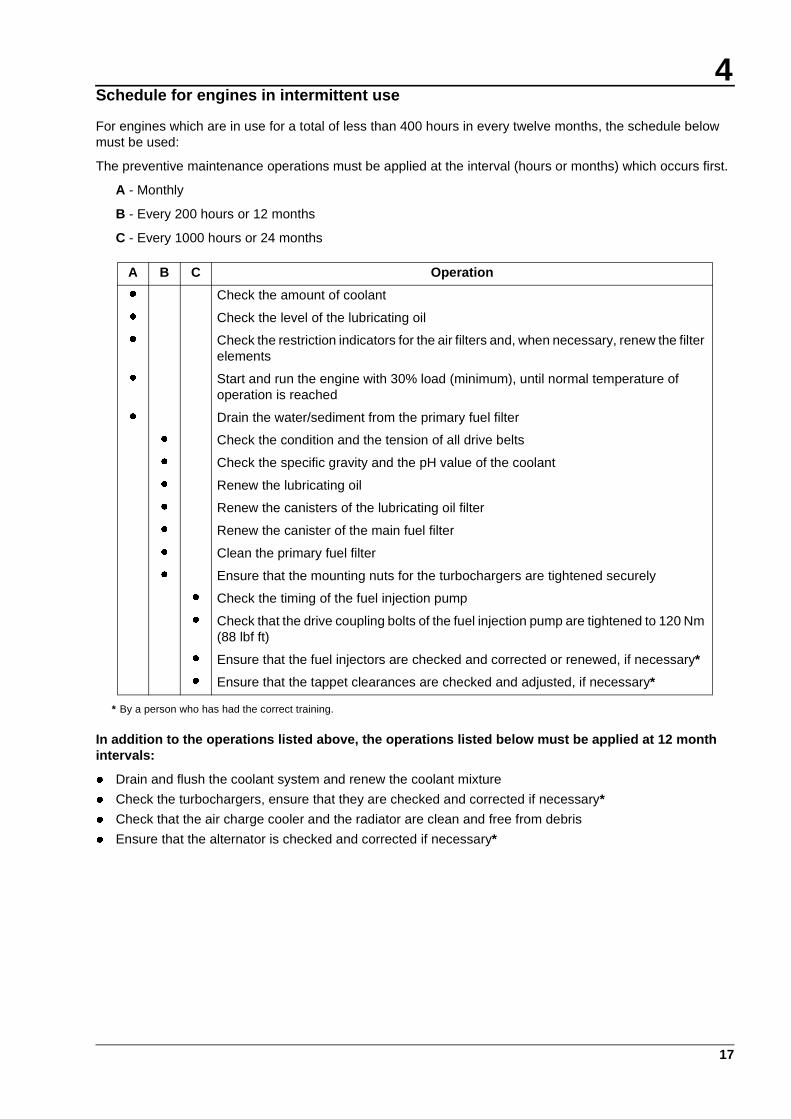
Schedule for engines in intermittent use
For engines which are in use for a total of less than 400 hours in every twelve months, the schedule below must be used:
The preventive maintenance operations must be applied at the interval (hours or months) which occurs first.
A - Monthly
B - Every 200 hours or 12 months
C - Every 1000 hours or 24 months
* By a person who has had the correct training.
In addition to the operations listed above, the operations listed below must be applied at 12 month intervals:
l Drain and flush the coolant system and renew the coolant mixture
l Check the turbochargers, ensure that they are checked and corrected if necessary*
l Check that the air charge cooler and the radiator are clean and free from debris
l Ensure that the alternator is checked and corrected if necessary*
A B C Operation
l Check the amount of coolant
l Check the level of the lubricating oil
l Check the restriction indicators for the air filters and, when necessary, renew the filter elements
l Start and run the engine with 30% load (minimum), until normal temperature of operation is reached
l Drain the water/sediment from the primary fuel filter
l Check the condition and the tension of all drive belts
l Check the specific gravity and the pH value of the coolant
l Renew the lubricating oil
l Renew the canisters of the lubricating oil filter
l Renew the canister of the main fuel filter
l Clean the primary fuel filter
l Ensure that the mounting nuts for the turbochargers are tightened securely
l Check the timing of the fuel injection pump
l Check that the drive coupling bolts of the fuel injection pump are tightened to 120 Nm (88 lbf ft)
l Ensure that the fuel injectors are checked and corrected or renewed, if necessary*
l Ensure that the tappet clearances are checked and adjusted, if necessary*
This document has been printed from SPI². Not for Resale

4
18
Coolant level
Remove the filler cap from the radiator and check that the level of the coolant mixture just touches the bottom of the filler tube inside the radiator. If necessary, add coolant until the level of the coolant reaches the filler tube. Fit the filler cap.
Caution: If coolant is added to the system during service, it must consist of the same original mixture as used to fill the system.
Warning! On a hot engine release the filler cap carefully as the system will be under pressure.
Lubricating oil level
At the periods given in the service schedule use the dipstick to check the amount of lubricating oil in the sump. While the engine runs, the oil level must be above the L mark. With the engine stopped the oil level must be at the H mark on the dipstick. If necessary, put more oil into the sump. Use the same grade and specification as that already in the system. Do NOT overfill.
This document has been printed from SPI². Not for Resale

4
19
Restriction indicator
Each air filter is fitted with an indicator (A) which gives a visual warning when the filter needs a service.
When the red warning indicator is seen through the clear panel after the engine has stopped, the air filter element must be renewed.
After a clean element has been fitted, press the reset button on the restriction indicator.
How to renew the elements of the air filters
The two air filters (B) contain paper elements. These must not be washed. Renew the paper elements as follows:
1 Loosen the clamp and remove the end cover (B1). Remove the wing nut (B2), withdraw and discard the filter element (B3).
2 Clean, thoroughly, the inside of the casing of the air filter. Fit a new filter element and fit the end cover.
3 Reset the restriction indicator.
Repeat this procedure for the other air filter.
How to drain the primary fuel filter
1 Remove the drain plug from the base of the filter bowl and allow any water or sediment to drain from the unit.
2 Fit the drain plug and tighten it securely.
A 37
B 21
1
2
3
This document has been printed from SPI². Not for Resale

4
20
How to check the drive belts
Check all drive belts and renew a belt if it is worn or damaged. Where more than one belt is used between two pulleys, all of the belts must be renewed together. Maximum belt life will be obtained only if the belts are kept at the correct tensions.
Check the belt tension at the centre of the longest free length, for example, position (A5) to check the fan drive belts.
Use a ‘Gates "Krikit" V-belt tension gauge’ or similar tool to check the tension of the belts.
The correct tension for all belts is 400 to 489 N (90 to 100 lbf). Where more than one belt is used between two pulleys, check/adjust the tension on the tightest belt.
Note: When new belts are fitted they must be checked again after the engine has been run for 15 minutes and, if necessary, adjusted to the correct tension.
How to adjust the tension of the fan belts
1 To adjust the tension of the fan belts, loosen the nuts on the adjustment bolt. Loosen the large lock nut (B1) on the belt tensioner and turn the adjustment bolt (B2) until the correct tension is obtained.
2 Tighten the lock nut and check the tension of the belts again.
3 Run the engine for 15 minutes and then check the belt tension again.
Check the tension of new belts every week for four weeks and then at the intervals specified in the service schedule
How to adjust the tension of the alternator belt
1 Loosen the alternator pivot bolt (A1), the adjustment link bolt (A3) and the adjustment bolt (A2). Move the alternator to obtain the correct belt tension and tighten the bolts.
2 Run the engine for 15 minutes and then check the belt tension again.
Check the tension of new belts every week for four weeks and then at the intervals specified in the service schedule.
How to renew the fan belts
1 To renew the fan belts, remove the six bolts which fasten the fan to the pulley and push the fan forward into the radiator cowl.
2 Release the tension on the belts and remove the old belts. Ensure that the pulley grooves are free from grease and dirt. Fit a new set of belts.
3 Fit the fan and tighten the bolts securely. Adjust the fan belts to the correct tension.
How to renew the alternator belt
1 Remove the fan belts from the crankshaft pulley as given on this page.
2 Loosen the adjustment bolts to release the tension on the alternator belt and remove the old belt. Check that the pulley grooves are clean and fit a new belt. Adjust the belt to the correct tension. Fit the fan belts as given on this page.
A 59
5
34
2
1
B 60
2
1
This document has been printed from SPI². Not for Resale
4
21
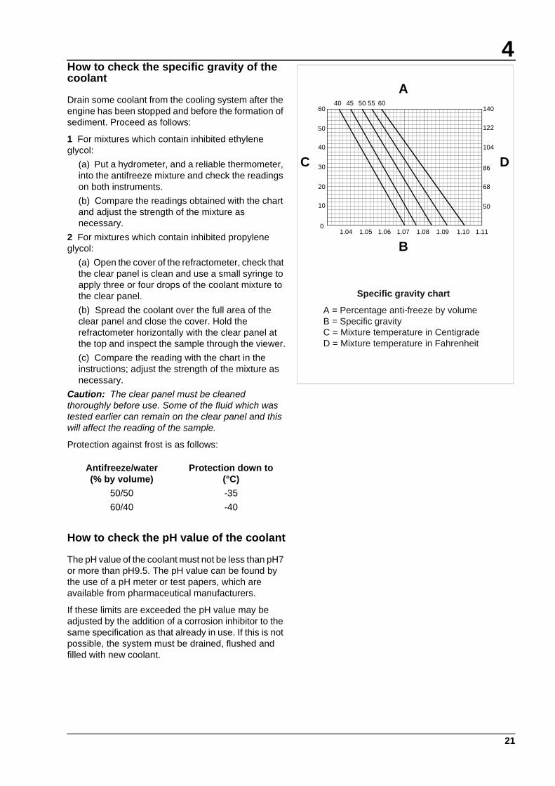
How to check the specific gravity of the coolant
Drain some coolant from the cooling system after the engine has been stopped and before the formation of sediment. Proceed as follows:
1 For mixtures which contain inhibited ethylene glycol:
(a) Put a hydrometer, and a reliable thermometer, into the antifreeze mixture and check the readings on both instruments.
(b) Compare the readings obtained with the chart and adjust the strength of the mixture as necessary.
2 For mixtures which contain inhibited propylene glycol:
(a) Open the cover of the refractometer, check that the clear panel is clean and use a small syringe to apply three or four drops of the coolant mixture to the clear panel.
(b) Spread the coolant over the full area of the clear panel and close the cover. Hold the refractometer horizontally with the clear panel at the top and inspect the sample through the viewer.
(c) Compare the reading with the chart in the instructions; adjust the strength of the mixture as necessary.
Caution: The clear panel must be cleaned thoroughly before use. Some of the fluid which was tested earlier can remain on the clear panel and this will affect the reading of the sample.
Protection against frost is as follows:
How to check the pH value of the coolant
The pH value of the coolant must not be less than pH7 or more than pH9.5. The pH value can be found by the use of a pH meter or test papers, which are available from pharmaceutical manufacturers.
If these limits are exceeded the pH value may be adjusted by the addition of a corrosion inhibitor to the same specification as that already in use. If this is not possible, the system must be drained, flushed and filled with new coolant.
Antifreeze/water(% by volume)
Protection down to(°C)
50/50 -35
60/40 -40
Specific gravity chart
A = Percentage anti-freeze by volumeB = Specific gravityC = Mixture temperature in CentigradeD = Mixture temperature in Fahrenheit
A
B
C D
1.04 1.05 1.06 1.07 1.08 1.09 1.10 1.11
40 45 50 55 6060
40
50
30
20
10
0
50
122
104
86
68
140
This document has been printed from SPI². Not for Resale

4
22
How to renew the engine lubricating oil
1 Operate the engine until it is warm.
2 Stop the engine, remove the sump drain plug and drain the lubricating oil from the sump. Fit the drain plug, complete with a new sealing washer, and tighten the plug to a torque of 47 Nm (35 lbf ft). If the plug is fitted to a steel insert, tighten the plug to a torque of 115 Nm (85 lbf ft).
3 Renew the three oil filter canisters as given below.
4 Clean the area around the oil filler cap (A2) and remove the cap. Fill the sump to the H mark on the dipstick (A1) with clean new lubricating oil of an approved grade as given on page 32. Do NOT overfill.
5 Operate the engine and check for leakage from the filter canisters. When the engine has cooled, check the oil level on the dipstick and put more oil into the sump, if necessary.
How to renew the canisters of the oil filter
Three screw-on type canisters are fitted to the filter head which is integral with the bottom of the engine oil cooler.
1 Put a tray under the canisters to retain the spilt lubricating oil. Use a strap wrench to remove each canister.
2 Check that the sealing rings (B1) are correctly fitted to the new canisters and clean the contact faces of the filter head.
3 Lubricate the top of each canister seal with clean engine lubricating oil and fill each canister with the approved grade of lubricating oil.
4 Fit the new canisters to their adaptors and tighten each canister until its sealing ring is just in contact with the face of the filter head. Continue to tighten each canister by a further 11/4 turns. Do NOT overtighten.
A 61
1
2
B 64
1
This document has been printed from SPI². Not for Resale

4
23
How to clean the primary fuel filter
1 Remove the three bolts (A1) and remove the filter bowl (A2).
2 Clean all of the components with paraffin and dry them with a compressed air jet.
3 Fit the bowl to the filter head, together with a new sealing ring. Align the clamp ring (A3) and fasten it with the three bolts.
Early engines can be fitted with filters that have elements which can be cleaned. These elements should be removed, cleaned with fuel oil and dried with a compressed air jet.
How to renew the canister of the main fuel filter
The main fuel filter is at the rear of the engine on the ‘B’ bank side and has two canisters. Both canisters must be renewed at the same time.
1 Clean the area around the filter and remove the fuel filter canisters. If necessary, use a strap wrench. Discard the canisters.
2 Check that the sealing ring (B1) is fitted correctly to each new canister and clean the contact faces of the filter head.
3 Lubricate the top of the canister seal (B1) with clean fuel oil and renew the sealing ring (B2) on the adaptor.
4 Fit the new canisters to their threaded adaptors and tighten each canister until the sealing ring just comes into contact with the filter head. Continue to tighten each canister by a further 11/4 turns by hand. Do NOT overtighten.
After the fuel filter canisters have been renewed, eliminate air from the low pressure fuel system as given on page 27.
A 65
1
2
3
B 66
1
2
This document has been printed from SPI². Not for Resale
4
24
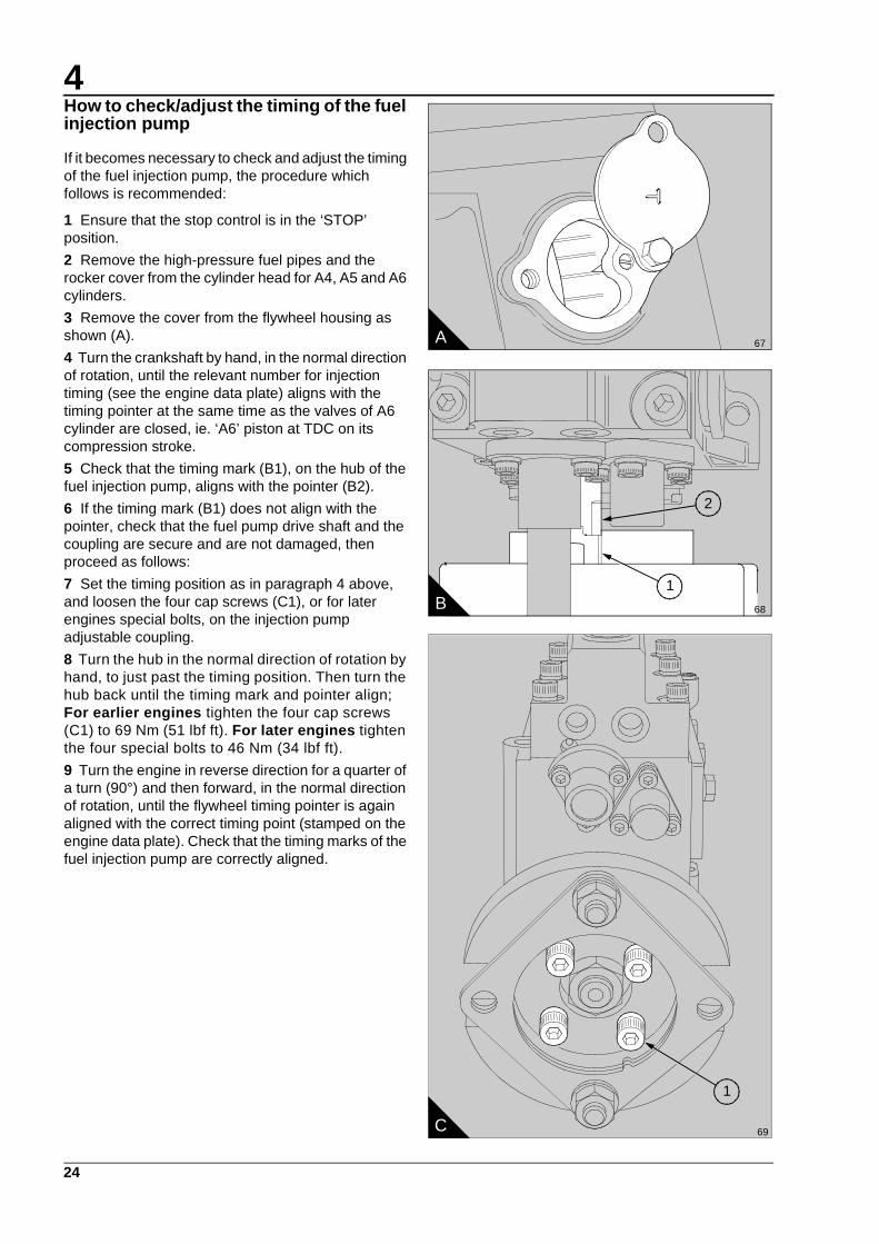
How to check/adjust the timing of the fuel injection pump
If it becomes necessary to check and adjust the timing of the fuel injection pump, the procedure which follows is recommended:
1 Ensure that the stop control is in the ‘STOP’ position.
2 Remove the high-pressure fuel pipes and the rocker cover from the cylinder head for A4, A5 and A6 cylinders.
3 Remove the cover from the flywheel housing as shown (A).
4 Turn the crankshaft by hand, in the normal direction of rotation, until the relevant number for injection timing (see the engine data plate) aligns with the timing pointer at the same time as the valves of A6 cylinder are closed, ie. ‘A6’ piston at TDC on its compression stroke.
5 Check that the timing mark (B1), on the hub of the fuel injection pump, aligns with the pointer (B2).
6 If the timing mark (B1) does not align with the pointer, check that the fuel pump drive shaft and the coupling are secure and are not damaged, then proceed as follows:
7 Set the timing position as in paragraph 4 above, and loosen the four cap screws (C1), or for later engines special bolts, on the injection pump adjustable coupling.
8 Turn the hub in the normal direction of rotation by hand, to just past the timing position. Then turn the hub back until the timing mark and pointer align; For earlier engines tighten the four cap screws (C1) to 69 Nm (51 lbf ft). For later engines tighten the four special bolts to 46 Nm (34 lbf ft).
9 Turn the engine in reverse direction for a quarter of a turn (90°) and then forward, in the normal direction of rotation, until the flywheel timing pointer is again aligned with the correct timing point (stamped on the engine data plate). Check that the timing marks of the fuel injection pump are correctly aligned.
A 67
2
1B 68
C 69
1
This document has been printed from SPI². Not for Resale
4
25
Fuel injector fault
A fuel injector fault can cause an engine misfire.
In order to find which injector is defective, operate the engine at a fast idle speed. Loosen and tighten the union nut of the high-pressure fuel pipe at each injector. When the union nut of the defective injector is loosened, it has little or no effect on the engine speed.
Warning! Ensure that the fuel does not spray onto your skin.
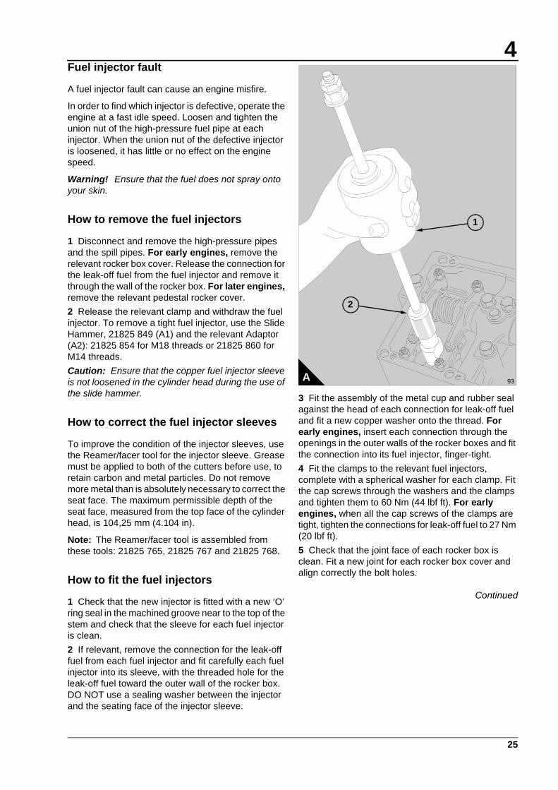
How to remove the fuel injectors
1 Disconnect and remove the high-pressure pipes and the spill pipes. For early engines, remove the relevant rocker box cover. Release the connection for the leak-off fuel from the fuel injector and remove it through the wall of the rocker box. For later engines, remove the relevant pedestal rocker cover.
2 Release the relevant clamp and withdraw the fuel injector. To remove a tight fuel injector, use the Slide Hammer, 21825 849 (A1) and the relevant Adaptor (A2): 21825 854 for M18 threads or 21825 860 for M14 threads.
Caution: Ensure that the copper fuel injector sleeve is not loosened in the cylinder head during the use of the slide hammer.
How to correct the fuel injector sleeves
To improve the condition of the injector sleeves, use the Reamer/facer tool for the injector sleeve. Grease must be applied to both of the cutters before use, to retain carbon and metal particles. Do not remove more metal than is absolutely necessary to correct the seat face. The maximum permissible depth of the seat face, measured from the top face of the cylinder head, is 104,25 mm (4.104 in).
Note: The Reamer/facer tool is assembled from these tools: 21825 765, 21825 767 and 21825 768.
How to fit the fuel injectors
1 Check that the new injector is fitted with a new ‘O’ ring seal in the machined groove near to the top of the stem and check that the sleeve for each fuel injector is clean.
2 If relevant, remove the connection for the leak-off fuel from each fuel injector and fit carefully each fuel injector into its sleeve, with the threaded hole for the leak-off fuel toward the outer wall of the rocker box. DO NOT use a sealing washer between the injector and the seating face of the injector sleeve.
3 Fit the assembly of the metal cup and rubber seal against the head of each connection for leak-off fuel and fit a new copper washer onto the thread. For early engines, insert each connection through the openings in the outer walls of the rocker boxes and fit the connection into its fuel injector, finger-tight.
4 Fit the clamps to the relevant fuel injectors, complete with a spherical washer for each clamp. Fit the cap screws through the washers and the clamps and tighten them to 60 Nm (44 lbf ft). For early engines, when all the cap screws of the clamps are tight, tighten the connections for leak-off fuel to 27 Nm (20 lbf ft).
5 Check that the joint face of each rocker box is clean. Fit a new joint for each rocker box cover and align correctly the bolt holes.
Continued
A 93
1
2
This document has been printed from SPI². Not for Resale
4
26
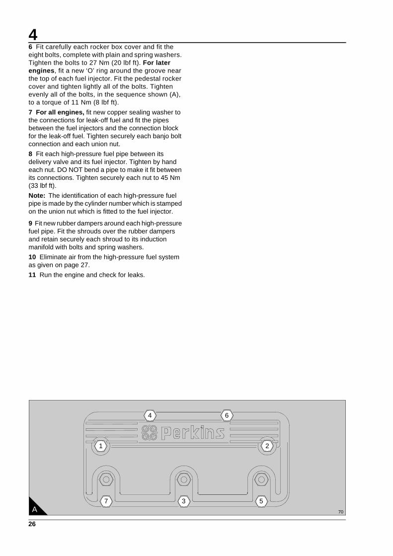
6 Fit carefully each rocker box cover and fit the eight bolts, complete with plain and spring washers. Tighten the bolts to 27 Nm (20 lbf ft). For later engines, fit a new ‘O’ ring around the groove near the top of each fuel injector. Fit the pedestal rocker cover and tighten lightly all of the bolts. Tighten evenly all of the bolts, in the sequence shown (A), to a torque of 11 Nm (8 lbf ft).
7 For all engines, fit new copper sealing washer to the connections for leak-off fuel and fit the pipes between the fuel injectors and the connection block for the leak-off fuel. Tighten securely each banjo bolt connection and each union nut.
8 Fit each high-pressure fuel pipe between its delivery valve and its fuel injector. Tighten by hand each nut. DO NOT bend a pipe to make it fit between its connections. Tighten securely each nut to 45 Nm (33 lbf ft).
Note: The identification of each high-pressure fuel pipe is made by the cylinder number which is stamped on the union nut which is fitted to the fuel injector.
9 Fit new rubber dampers around each high-pressure fuel pipe. Fit the shrouds over the rubber dampers and retain securely each shroud to its induction manifold with bolts and spring washers.
10 Eliminate air from the high-pressure fuel system as given on page 27.
11 Run the engine and check for leaks.
A 70
7 3
4
1
5
6
2
This document has been printed from SPI². Not for Resale
4
27
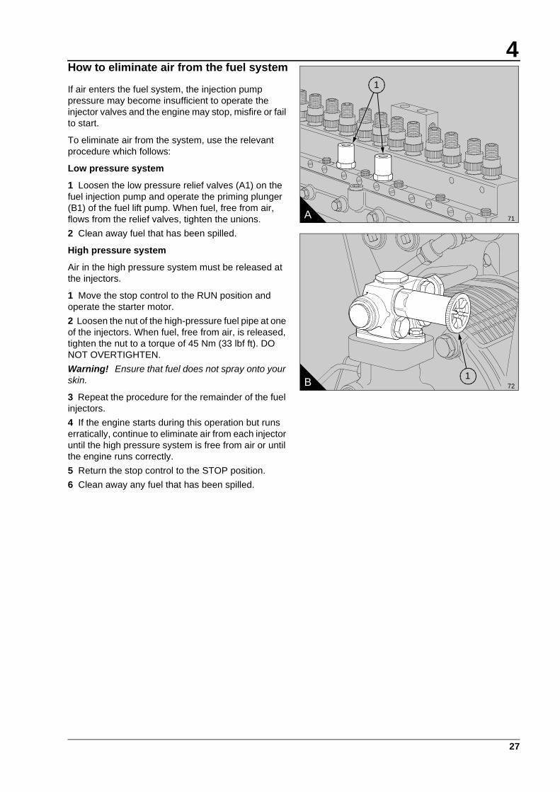
How to eliminate air from the fuel system
If air enters the fuel system, the injection pump pressure may become insufficient to operate the injector valves and the engine may stop, misfire or fail to start.
To eliminate air from the system, use the relevant procedure which follows:
Low pressure system
1 Loosen the low pressure relief valves (A1) on the fuel injection pump and operate the priming plunger (B1) of the fuel lift pump. When fuel, free from air, flows from the relief valves, tighten the unions.
2 Clean away fuel that has been spilled.
High pressure system
Air in the high pressure system must be released at the injectors.
1 Move the stop control to the RUN position and operate the starter motor.
2 Loosen the nut of the high-pressure fuel pipe at one of the injectors. When fuel, free from air, is released, tighten the nut to a torque of 45 Nm (33 lbf ft). DO NOT OVERTIGHTEN.
Warning! Ensure that fuel does not spray onto your skin.
3 Repeat the procedure for the remainder of the fuel injectors.
4 If the engine starts during this operation but runs erratically, continue to eliminate air from each injector until the high pressure system is free from air or until the engine runs correctly.
5 Return the stop control to the STOP position.
6 Clean away any fuel that has been spilled.
A 71
1
B 72
1
This document has been printed from SPI². Not for Resale

4
28
How to check the tappet clearances
The tappet clearance is measured between the rocker levers and the top of the valve bridge pieces. See page 45 for the size of the clearances.
Each valve bridge piece controls two valves. An adjustment screw and lock nut is fitted to each bridge piece to ensure that equal force is applied to both valves from the rocker arm.
Before the tappet clearances are adjusted, the valve bridge pieces MUST be checked and adjusted if necessary.
Check and adjust the valve bridge pieces and tappet clearances while the fuel injectors are removed for service.
Caution: Numbers A1 and B1 cylinders are at the front (fan end) of the engine.
1 Remove the air filters, the high pressure fuel pipes and the fuel injector leak-off pipes.
2 Remove the rocker covers.
3 Turn the crankshaft in the normal direction of rotation until the inlet valve of number A1 cylinder has just opened and the exhaust valve of the same cylinder has not closed completely.
Check and, if necessary, adjust the valve bridge pieces of only the cylinder numbers which follow:
Inlet: A2, A4, A6, B1, B3, B5Exhaust: A3, A5, A6, B1, B4, B5
To adjust the valve bridge pieces, proceed as follows: Loosen the lock nut and the adjustment screw on the relevant bridge piece. Use the rocker lever to apply pressure to the bridge piece, then turn the adjustment screw until it is just in contact with the tip of the valve stem (A). Hold the adjustment screw in this position with a screwdriver and tighten the lock nut to a torque of 40 Nm (30 lbf ft). Use a torque wrench with a ring spanner adaptor. Note that the reading on the torque wrench must be adjusted to compensate for the extra length caused by the ring spanner adaptor.
Check the tappet clearance AFTER the bridge pieces have been adjusted. When the clearance has been set correctly (B), tighten the lock nut to a torque of 40 Nm (30 lbf ft).
4 Turn the crankshaft 360°, in the normal direction of rotation until the inlet valves of number A6 cylinder have just opened and the exhaust valves of the same cylinder have not closed completely. Check and, if necessary, adjust the valve bridge pieces of only the cylinder numbers which follow:
Inlet: A1, A3, A5, B2, B4, B6Exhaust: A1, A2, A4, B2, B3, B6
Check the tappet clearance AFTER the bridge pieces have been adjusted. When the clearance has been set correctly (B), tighten the lock nut to a torque of 40 Nm (30 lbf ft).
5 When all of the bridge pieces and tappet clearances have been checked/adjusted, apply oil to the rocker levers, the bridge pieces and the valve springs. Fit the rocker covers, the fuel pipes and the air filters.
74A
73B
This document has been printed from SPI². Not for Resale

4
29
Turbochargers
At the periods given in the service schedule, disconnect and remove the pipes from between the air filters and the turbochargers. Turn, rapidly, the rotor assembly of each turbocharger, check for freedom of movement and for sounds of interference.
Deposits must not be removed from the turbine wheels nor the compressor wheels or the balance of the assemblies will be adversely affected.
Alternator
At the periods specified in the service schedule clean the outside of the alternator and ensure that the ventilation holes are clean. Contamination near to the diodes can cause sparks and must be removed with an approved cleaning fluid. A recommended fluid is Electronic Cleaning Fluid, Grade 8-23, available in aerosol containers or in larger quantities from Applied Chemicals Limited, Uxbridge, Middlesex.
The alternator must be checked and corrected, if necessary, by a person who has had the correct training, at the periods given in the service schedule.
How to drain the coolant system
Drain and flush the coolant system every 12 months or less. The system must be drained as soon as possible after the engine is stopped and before any deposits in the coolant have fallen to the bottom.
1 Ensure that the engine is level.
2 Carefully remove the header tank filler cap, especially if the engine is hot.
Warning! Take care during removal of the filler cap as the coolant system will be under pressure.
3 Remove the coolant drain plugs from the front left side and the rear right side of the engine. Ensure that the drain holes are not restricted.
4 Flush the system with clean water.
5 Fit the engine and radiator drain plugs.
6 Fit a ‘coolant drained’ label if the coolant system is not to be filled immediately.
How to clean the coolant system
The coolant system must be drained and flushed through with clean water until it flows clear from all of the drain taps.
If the system has become contaminated, it must be cleaned. Use clean water with 1% of Symperonic ‘N’. This is equivalent to 10ml/litre or 45 ml/UK gallon.
1 Fill the system with clean water, at the same time add the necessary amount of Symperonic ‘N’ at the filler cap.
2 Operate the engine until the coolant reaches the normal temperature of operation, then operate the engine at maximum rated speed for 10 minutes.
Caution: In very cold ambient conditions, the thermostat may not open to allow full circulation of the cleaning fluid. If this occurs the engine must be operated on load. The thermostat is open when the pipe between the thermostat housing and the radiator is hot. If the pipe is cool, the thermostat valve is closed.
3 Stop the engine and drain immediately the coolant from all of the drain taps or plugs.
Warning! Take care during removal of the filler cap as the coolant system will be under pressure.
4 Allow the engine to cool, then fill the system with clean water. Allow a minimum of 5 litres (1 UK gallon) to drain from the system before the drain taps are closed.
5 Operate the engine as in operation 2, but maintain maximum speed for 5 minutes only.
6 Repeat the operations in paragraphs 3, 4 and 5.
7 Drain the system completely and close the drain taps. Fill the system with the correct coolant mixture.
How to fill the coolant system
Fill the system slowly, with the approved coolant mixture, until the coolant is just in contact with the bottom of the filler extension tube in the radiator. Operate the engine until the coolant reaches the normal temperature of operation. Stop the engine, check the coolant level and, if necessary, add extra coolant.
Warning! Take care during removal of the filler cap as the coolant system will be under pressure.
This document has been printed from SPI². Not for Resale

This document has been printed from SPI². Not for Resale

31
5Engine fluids 5
Diesel fuel
Diesel fuel must conform to the specifications given below:
On highway
BS EN 590 1997 - maximum sulphur content 0.05%; minimum cetane number 49 and minimum cetane index 46.
Low sulphur fuels must conform to a lubricity performance such that when tested using HFRR (CEC F-06-A96) the wear scar meets a maximum of 460 microns.
Off highway
BS 2869: Part 2 1998 Class A2 - maximum sulphur content 0.20%; minimum cetane number 45 and minimum cetane index 45.
The use of fuels which do not conform to the above standards can cause damage and/or reduced engine life and could affect the warranty. Further details can be obtained from the Service Department at Perkins Engines Company Limited, Shrewsbury.
Coolant
Coolant mixture
The coolant approved for use in all diesel engines manufactured by PE(S)L is a mixture of 50% inhibited ethylene glycol, or inhibited propylene glycol, and 50% clean soft water.
Mixtures which contain methanol are NOT approved.
The corrosion inhibitor in the anti-freeze or coolant concentrate, must be based on sodium nitrite, sodium benzoate, sodium borate, sodium metasillicate and benzotriazole.
Amines or phosphates must not be used. If operators are in doubt, they should consult their source of supply.
In addition, all products which are used should conform to BS 6580-1992.
For marine engines and engines which have aluminium water-cooled exhaust manifolds, only ‘BASF 007/400F’ or Perkins anti-freeze are approved. The Perkins anti-freeze, part numbers 21825 166 (1 litre) and 21825 167 (5 litre), can be obtained from the Perkins worldwide distributor network.
Caution: Do NOT use salt water or any other coolant which can cause corrosion in the closed coolant circuit.
Corrosion inhibitor
If anti-freeze is not available and is not required then clean soft water, with 1% of PE(S)L corrosion inhibitor, may be used. This ratio is equivalent to 0,5 litres of corrosion inhibitor to 50 litres (11 UK gallons) of water. The corrosion inhibitor is available from the Perkins worldwide distributor network, part number 21825 735 (1 litre). The use of this product should be controlled in accordance with the manufacturer’s instructions. For CHP (combined heat and power) sets an alternative inhibitor, part number OE45765, is recommended at a strength of 3%.
Water quality
Soft water means de-ionised water, distilled water, rain water, or water from a mains supply which has a maximum combined chloride and sulphate level of 150 mg/litre and a maximum total hardness of 250 mg/litre.
1 If soft water is not used, the cooling system may be affected by the formation of hard deposits which can cause the engine to overheat. This is especially important for engines which have coolant added frequently.
2 The use of products which are not approved for the cooling system may cause serious problems. Coolant mixtures with insufficient corrosion inhibitor can cause erosion and/or corrosion of the cooling system components.
This document has been printed from SPI². Not for Resale

5
32
Lubricating oil
1 Viscosity - Perkins Engines Company Limited recommend the use of SAE15W/40 for all engines that work in ambient temperatures above -15°C (5°F). Below -15°C (5°F) and down to -20°C (-4°F) the use of a 10W/30 oil is recommended. Down to -30°C (-22°F) a 5W/40 fully synthetic oil is recommended. For engines which operate in arctic conditions, below -30°C (-22°F), contact the Service Department at Perkins Engines Company Limited, Shrewsbury.
2 Performance Specification - For heavy duty operation, base load, or extended drain (Eagle Tx only), super high performance oils (SHPD) must be used. These oils exceed the requirements of ACEA E3 and are listed in the ‘preferred’ columns of the table shown.
For light duty operation, oils which exceed the requirements ACEA E2 may be used. These oils are listed in the ‘acceptable’ columns of the table shown.
It is recommended that the operator uses oils shown in the ‘preferred’ columns as these give the greatest protection.
This document has been printed from SPI². Not for Resale

5
33
Below is a list of oils recommended by Perkins Engines Company Limited, Shrewsbury. The operator must ensure that the oil used conforms to the above requirements.
Recommended oils for Europe
Manufacturer of lubricating oil
Preferred multi-grade oils which conform to ACEA E3
Acceptable multi-grade oils which conform to ACEA E2
AGIP Sigma Turbo 15W/40Blitum T 15W/40
Universal Multifleet 15W/40Master Super Turbo SHPD 15W/40
BP Vanellus C3 Extra 15W/40Vanellus FE Extra10W/40Vanellus HT 10W/40Vanellus HT Extra 10W/40
Vanellus C3 Multi-grade 15W/40
CALTEX ONLY AVAILABLE IN FAR EAST, MIDDLE EAST, SOUTHERN AND EASTERN AFRICA AND AUSTRALASIA
CASTROL Syntruck 5W/40Dynamax 10W/40Turbomax 15W/40
RX Super Plus 15W/40
CHEVRON Delo XLD 15W/40Delo SHP 15W/40
Delo 500 15W/40
ELF Performance EXPERTY 10W/40Performance TROPHY DX 15W/40
Performance Super D 15W/40Performance 3D 15W/40
ESSO Essolube XTS 501Essolube XT 401
Essolube XTS 301Essolube XT 301
FINA Kappa First 5W/30Kappa Extra 15W/40Kappa Ultra 10W/40
Kappa Supra 15W/40
FUCHS Turbolene HPE 15W/40Titan Unic Plus 10W/40Titan Cargo MC 10W/40
Titan Formel Plus 15W/40Turbolene D 15W/40Turbolene D Plus 15W/40
KUWAIT Q8T 700 15W/40Q8T 710 15W/40Q8T 800 10W/40
Q8T 500 15W/40
MILLERS Multifleet XPD 15W/40Truckmaster Global XD 15W/40Truckmaster XHFE 10W/40
Maxifleet MP 15W/40Suprex 15W/40
MOBIL Delvac 1 SHC 5W/40Delvac XHP 15W/40Delvac HP 15W/40
Delvac MX 15W/40
MORRIS XHD Plus 15W/40XHD FE 10W/40Ring Free Ultra 10W/40
Duplex CDX 15W/40XHD 15W/40
SHELL Rimula Ultra 5W/30Rimula Super 15W/40
Rimula X 15W/40Rimula TX 15W/40
SUN Super HPD 15W/40 Forza 15W/40
TEXACO URSA Super TDX 10W/40URSA Super TD 15W/40
URSA Super LA 15W/40
TOTAL Rubia TIR 8600 10W/40Rubia TIR 6400 15W/40
Rubia 4400 15W/40Rubia XT 15W/40
This document has been printed from SPI². Not for Resale

5
34
Recommended oils for remainder of the world
Warranty
The engine must be operated with the approved fuel, lubricant and coolant, and maintained in accordance with the service schedule or the warranty can become invalid.
Manufacturer of lubricating oil
Mono-grade oils which conform to ACEA E2
Preferred multi-grade oils which conform to
ACEA E3
Acceptable multi-grade oils which conform to
ACEA E2
AGIP Sigma Turbo 15W/40Blitum T 15W/40
Universal Multifleet15W/40Master Super Turbo SHPD 15W/40
BP Vanellus C3 30Vanellus C3 40
Vanellus C3 Extra 15W/40Vanellus FE Extra 10W/30
Vanellus C3 multi-grade15W/40
CALTEX Delo SHP SAE 30 andSAE 40Delo 600 SAE 30 andSAE 40Delo 350 SAE 30 andSAE 40
Delo XLD multi-gradeSAE 10W/40
Delo SHP multi-grade SAE 15W/40Delo 600 multi-gradeSAE 15W/40Delo 350 multi-gradeSAE 15W/40
CASTROL Syntruck 5W/40Dynamax 10W/40Turbomax 15W/40
RX Super Plus 15W/40
CHEVRON Delo 1000 MarineSAE 30 or 40
Delo 400 multi-gradeSAE 15W/40
RPM Heavy Duty Motor oil 15W/40
ELF Performance Super DSAE 30 and 40Performance 3D SAE 30 and 40
Performance TROPHY DX 15W/40
Performance Super D 15W/40Performance 3D 15W/40
ESSO Essolube X 301 SAE 30Essolube X 301 SAE 40Essolube XD 3+ SAE 30Essolube XD 3+ SAE 40
Essolube XT 431Essolube XD 3 Extra+
Essolube XT 331Essolube XD 3+
FINA Kappa Super 30Kappa Super 40
Kappa First 5W/30Kappa Extra 15W/40Kappa Ultra 10W/40
Kappa Supra 15W/40
KUWAIT Q8T 500 SAE 30Q8T 500 SAE 40
Q8T 700 15W/40Q8T 710 15W/40Q8T 800 10W/40
Q8T 500 15W/40
MOBIL Delvac 1430Delvac 1330
Delvac 1 SHC 5W/40Delvac XHP 15W/40Delvac HP 15W/40
Delvac MX 15W/40
MORRIS XHD SAE 30 or 40 XHD Plus 15W/40XHD FE 10W/40
Duplex CDX 15W/40XHD 15W/40
SHELL Rimula X 30Rimula X 40
Rimula Ultra 5W/30Rimula Super 15W/40
Rimula X 15W/40Rotella TX 15W/40
SUN Super HPD 40 Super HPD 15W/40 Forza 15W/40
TEXACO URSA Super LA 30URSA Super LA 40
URSA Super TDX 10W/40URSA Super TD 15W/40
URSA Super LA 15W/40
TOTAL Rubia FP 40 Rubia TIR 8600 15W/40Rubia TIR 6400 15W/40
Rubia 4400 15W/40Rubia XT 15W/40
This document has been printed from SPI². Not for Resale

35
6Fault diagnosis 6
Continued
This document has been printed from SPI². Not for Resale

6
36
Problems and possible causes
Problem
Possible causes
Checks by the userChecks by service
personnel
The starter motor turns the engine too slowly 1, 2, 3, 4
The engine will not start 5, 6, 7, 8, 9, 10, 12, 13, 14, 15, 17
34, 35, 36, 37, 38, 42, 43, 44
The engine is difficult to start 5, 7, 8, 9, 10, 11, 12, 13, 14, 15, 16, 17, 19
34, 36, 37, 38, 40, 42, 43, 44, 64
Not enough power 8, 9, 10, 11, 12, 13, 16, 17, 18, 19, 20, 21
34, 36, 37, 38, 39, 42, 43, 44, 61, 63, 64
Misfire 8, 9, 10, 12, 13, 15, 20, 22 34, 36, 37, 38, 39, 40, 41, 43
High fuel consumption 11, 13, 15, 17, 18, 19, 21, 22
34, 36, 37, 38, 39, 40, 42, 43, 44, 63, 64
Black exhaust smoke 11, 13, 15, 17, 19, 21, 22 34, 36, 37, 38, 39, 40, 42, 43, 44, 61, 63, 64
Blue or white exhaust smoke 4, 15, 21, 23 36, 37, 38, 39, 42, 44, 45, 52, 58, 62
The pressure of the lubricating oil is too low 4, 24, 25, 26 46, 47, 48, 50, 51, 59
The engine knocks 9, 13, 15, 17, 20, 22, 23 36, 37, 40, 42, 44, 46, 52, 53, 60
The engine runs erratically 7, 8, 9, 10, 11, 12, 13, 15, 16, 18, 20, 22, 23
34, 38, 40, 41, 44, 52, 60
Vibration 13, 18, 20, 27, 28 34, 38, 39, 40, 41, 44, 52, 54
The pressure of the lubricating oil is too high 4, 25 49
The engine temperature is too high 11, 13, 15, 19, 27, 29, 30, 32
34, 36, 37, 39, 52, 55, 56, 57
Crankcase pressure 31, 33 39, 42, 44, 45, 52
Bad compression 11, 22 37, 39, 40, 42, 43, 44, 45, 53, 60
The engine starts and stops 10, 11, 12 6, 7, 8, 9, 10, 12, 16, 34, 35
This document has been printed from SPI². Not for Resale

6
37
Code list of possible causes
1 The battery capacity is low.
2 A bad electrical connection.
3 A fault in the starter motor.
4 The wrong grade of lubricating oil.
5 The starter motor turns the engine too slowly.
6 The fuel tank is empty.
7 A fault in the stop control.
8 A restriction in a fuel pipe.
9 A fault in the fuel lift pump.
10 A dirty element of the fuel filter.
11 A restriction in the air filter or the induction system.
12 There is air in the fuel system.
13 A fault in the fuel injectors, or the fuel injectors are of the wrong type.
14 The cold start system is not used correctly.
15 A fault in the cold start system.
16 A restriction in the vent of the fuel tank.
17 The wrong type or grade of fuel has been used.
18 A restriction in the movement of the engine speed control.
19 A restriction in the exhaust pipe.
20 The engine temperature is too high.
21 The engine temperature is too low.
22 The tappet clearances are incorrect.
23 Too much oil, or oil of a wrong specification is used in a wet type air cleaner.
24 Not enough lubricating oil in the sump.
25 A defective gauge.
26 A dirty element of the lubricating oil filter.
27 The fan is damaged.
28 A fault in the mountings of the engine or the flywheel housing.
29 Too much lubricating oil in the sump.
30 A restriction in the air passages or in the water passages of the radiator.
31 A restriction in the breather.
32 There is insufficient coolant in the system.
33 A fault in the exhauster, or there is a leakage in the vacuum pipe.
34 A fault in the fuel injection pump.
35 A broken drive on the fuel injection pump.
36 The timing of the fuel injection pump is incorrect.
37 The valve timing is incorrect.
38 There is bad compression.
39 The cylinder head gasket leaks.
40 The valves are not free.
41 Wrong high-pressure pipes.
42 The cylinder bores are worn.
43 A leakage between the valves and the seats.
44 The piston rings are not free, or they are worn or damaged.
45 The valve stems and/or the guides are worn.
46 The crankshaft bearings are worn or damaged.
47 The lubricating oil pump is worn.
48 The relief valve does not close.
49 The relief valve does not open.
50 The spring of the relief valve is broken.
51 A fault in the suction pipe of the lubricating oil pump.
52 A piston is damaged.
53 The piston height is incorrect.
54 The flywheel housing, or the flywheel, is not aligned correctly.
55 A fault in the thermostat or the thermostat is of a wrong type.
56 A restriction in the coolant passages.
57 A fault in the water pump.
58 There is damage to the oil seals (if they are fitted) of the valve stems.
59 A restriction in the sump strainer.
60 A valve spring is broken.
61 The impeller of the turbocharger is damaged or is dirty.
62 Leakage of lubricating oil from the oil seal of the turbocharger.
63 The induction system leaks (turbocharged engines).
64 Damaged or defective waste-gate (if fitted).
This document has been printed from SPI². Not for Resale

This document has been printed from SPI². Not for Resale

39
7Engine preservation 7
Introduction
The recommendations indicated below are designed to prevent damage to the engine when it is withdrawn from service for a prolonged period. Use these procedures after the engine is withdrawn from service. Where necessary protect the engine against frost damage.
Short period storage
Up to seven days:
No treatment is necessary.
Up to three months:
Each week, operate the engine until the normal temperature of operation is reached. If the engine cannot be operated, turn the crankshaft by hand, in the normal direction of rotation (anti-clockwise as seen on the flywheel), a minimum of three revolutions.
Long period storage
If it is necessary to put an engine in storage for a period of between three and twelve months, use this procedure:
1 Remove the thermostat from its housing and carefully clean. Apply a silicone grease, such as MS4, to the valve stems of the thermostat and operate the valves by hand to ensure that the grease enters the glands. Fit the thermostat to its housing.
2 Operate the engine until normal temperature of operation is reached. Stop the engine and immediately drain the lubricating oil from the sump and from the canisters of the oil filter (see ’Caution’ on page 40).
3 Fill the canisters of the oil filter with PX4 corrosion inhibitor and fit the canisters to the filter head (on page 22).
4 Fill the sump, to the normal oil level, with PX4 corrosion inhibitor and, once again, run the engine until normal temperature of operation is reached.
5 Stop the engine, disconnect the fuel supply pipe and connect the pipe to a supply of PX4 corrosion inhibitor. Start the engine, while it is still hot, and operate the engine, with no load, for ten minutes. Stop the engine.
6 Disconnect the supply of PX4 corrosion inhibitor from the fuel system and seal the end of the pipe. Drain the fuel filters (see ‘Caution’ on page 40).
Fasten a label, at a position where it will be seen, to indicate that the fuel system has been disconnected.
7 Remove the fuel injectors and put the injectors in a container of PX4 corrosion inhibitor.
8 Set the fuel control lever to the NO FUEL position, remove the rocker covers and disconnect the air inlet pipes from the induction manifolds.
9 Turn the engine by use of the starter and, at the same time, spray PX4 corrosion inhibitor into the manifolds until an emission of vapour is seen from each injector opening. Connect the air inlet pipes.
10 Spray 40 cc of PX4 corrosion inhibitor into each cylinder, through the fuel injector openings. Fit the injectors.
Caution: The engine must NOT be turned after this operation and a label must be fitted to this effect.
11 Spray PX4 corrosion inhibitor around the valves and around the rocker assemblies. Refit the rocker covers.
12 Drain the PX4 corrosion inhibitor from the engine sump and from the oil filter canisters. Fit a NO OIL label to the oil filler cap.
13 Drain the cooling system and fill with the recommended coolant mixture (see page 31).
Caution: The mixture must NOT contain less than 50% inhibited ethylene glycol or propylene glycol, and may contain up to 90% by volume.
14 Wait for 15 minutes, then drain the coolant mixture completely. Fit a NO COOLANT label to the radiator filler cap.
15 Disconnect the exhaust pipe at the turbocharger outlet. Inject 2 grammes of VPI 260 powder into the turbocharger outlet and fit a blanking plug. Do NOT connect the exhaust pipe.
16 Disconnect the air pipes between the air filters and the turbocharger.
17 Inject 2 grammes of VPI 260 powder into the turbocharger.
Continued
This document has been printed from SPI². Not for Resale

7
40
18 Inject 2 grammes of VPI 260 powder into each paper element type air filter. Other types of air cleaners may be sprayed inside with PX4 corrosion inhibitor or with VPI 260 powder. Fit the air pipes.
19 Spray Crodafluid PM47 onto areas of the engine and auxiliary equipment which are not protected by paint. Ensure that the fuel control linkage is sprayed with Crodafluid PM47.
Warning! Do NOT spray PM47 into the vent holes of the alternator.
20 Cover, completely, the alternator and the starter motor in mouldable wax wrapping, and seal with adhesive tape.
21 Seal the air filter inlets, the crankcase breather and all other openings with mouldable wax wrapping and adhesive tape.
22 Remove all drive belts, apply French chalk to the belts and put them in a sealed plastic bag. Fasten the bag to the engine.
23 Fasten to the engine a label that indicates:
(a) That the exhaust system has been sealed.
(b) The dates when corrosion inhibitor was applied to the engine and when it must be applied again.
If the engine is to remain in storage for more than one year, the above procedure must be repeated at the end of each period of twelve months.
Removal from storage
To prepare the engine for use, after it has been in storage, refer to Section 3 - Operation instructions. The information given applies to new engines and to those removed from storage.
Caution: The canisters of the oil and fuel filters are designed so that when fitted upside down, the lubricating oil or fuel does not drain from the canister, when the engine is stopped.
To drain a canister, hold the canister over a suitable container, insert a small tool into one of the inlet openings and carefully press open the rubber, non-return seal. During this operation, do not damage the rubber seal or the element of the filter.
This document has been printed from SPI². Not for Resale

7
41
Approved products for engine preservation
Component Product Manufacturer
Thermostat MS4 silicone grease Ambersil LimitedWhitney RoadBasingstokeHampshire
Lubrication system PX4 corrosion inhibitor Croda Chemicals LimitedChurchill RoadDoncasterYorkshire
Fuel system PX4 corrosion inhibitor Croda Chemicals Limited
Valves and rocker assemblies PX4 corrosion inhibitor Croda Chemicals Limited
Cooling system Inhibited ethylene glycol or Inhibited propylene glycol
Various
Induction/exhaust systems PX4 corrosion inhibitor
VPI 260 powder
Croda Chemicals Limited
Shell Chemicals LimitedStanlow TerminalEllesmere PortCheshire
Engine and auxiliaries - outer casing
Crodafluid PM47
Mouldable wax wrapping
Croda Chemicals Limited
Carrs Paper LimitedShirleySolihullWest Midlands
This document has been printed from SPI². Not for Resale

This document has been printed from SPI². Not for Resale

43
8Parts and Service 8
Introduction
If problems occur with your engine or with the components fitted to it, your Perkins distributor can make the necessary repairs. Your Perkins distributor will ensure that only the correct parts are fitted and that the work is done correctly.
Certain components can be supplied by your Perkins distributor through the Perkins Exchange Component Programme. These will enable you to reduce the cost of certain repairs.
Service literature
Workshop manuals and other service publications are available from your Perkins distributor at a nominal cost.
Training
Courses on the service and overhaul of the 3000 Series range of engines are available at the Factory. For details, apply to: The Customer Training Centre, Perkins Engines Company Limited, Shrewsbury, SY1 3NX, England.
Service Bulletins
Service procedures and engine design are checked continuously at Perkins. As a result of this development work, it may become necessary to alter the information in manuals and other service publications. Between revisions of the literature, all relevant personnel are provided with full details of changes as they occur. The information is produced as a Service Bulletin; these are supplied to distributors for distribution as necessary.
Changes to engine design and service procedures are published as Service Bulletins for addition to any relevant Manuals.
This document has been printed from SPI². Not for Resale

This document has been printed from SPI². Not for Resale
45
9Engine data 9
3012 diesel engine
GeneralNumber of cylinders 12
Cylinder arrangement 60 degree included angle ’V’
Cycle Four stroke
Induction system Turbocharged and intercooled
Combustion system Direct injection
Nominal bore 135 mm (5.315 in)
Stroke 152 mm (5.984 in)
Compression ratio 14.5:1
Cubic capacity 26,11 litres (1593 in3)
Firing order A6, B1, A3, B4, A5, B2, A1, B6, A4, B3, A2, B5
Tappet clearances (hor or cold)Engines before build line number 8281(6C27437/29):
InletExhaust
Engines from build line number 8281 (6C27437/29):
InletExhaust
0,4 mm (0.016 in)0,5 mm (0.020 in)
0,2 mm (0.008 in)0,5 mm (0.020 in)
Direction of rotation Anti-clockwise: From the rear of the engine
Injection timing As stamped on engine data plate
Dry weight of engine(Approximate)
Electropak 2365 kg (5214 lb)Engine only 2120 kg (4674 lb)
Cooling systemCoolant pump Centrifugal, gear driven unit
Capacity of coolant systemEngine and pipeworkEngine and radiator pack
68 litres (15 UK gallons)122,7 litres (27 UK gallons)
Coolant system pressure(at normal working temperature)
up to 69 kN/m² (10 lbf/in²)
Temperature (normal) 70 to 100°C
Thermostat two, wax capsule type
Fuel systemType Low pressure supply to injection pump with through flow return to
tank
Injection pump 12 element, in-line unit
Governor Mechanical, integral with fuel injection pump
This document has been printed from SPI². Not for Resale
9
46
Lift pump Mechanical, operated by camshaft
Fuel supply pressure 140 to 210 kN/m² (20 to 30 lbf/in²)
Fuel injectors Axial feed, low spring type. Six spray holes
Injection pressure 250 bar (early engines 240 bar)
Main fuel filter Two screw-on type canister
Primary fuel filter/water separator Centrifugal type
Lubrication systemType Wet sump
Capacity of lubricating oil sumpMaximumMinimum
55 litres (12 UK gallons)33 litres (7.3 UK gallons)
Total capacity of lubricatingoil system
73,8 litres (16.3 UK gallons)
Lubricating oil pressureNormal load conditionsMinimum at rated speed
448 kN/m² (65 lbf/in²)345 kN/m² (50 lbf/in²)
Pump Spur gear type, gear driven
Pressure relief valveOpening pressure
Spring loaded plunger, not adjustable488 kN/m² (71 lbf/in²)
Oil-to-coolant heat exchanger Multiple tube type
Filters Three screw-on type canisters with integral by-pass valves
Maximum recommended temperature of sump oil
125°C
Induction/exhaust systemAspiration Pressure charged by two turbochargers
Air charge cooler (if fitted)TAGTWG
Two, air-to-air type, integral with radiatorTwo, air-to-coolant type, integral with induction manifolds
Air filters Two paper element type
Electrical equipmentAlternator Belt driven, 28 volt 40 amp, with integral regulator
Starter motor Single, 24 volt - flange mounted
Stop control Electrical, 24 volt, energised to RUN
Engine protection switches Coolant temperature switch, set to stop the engine at 106°COil pressure switch, set to stop the engine at 124 kN/m² (18 lbf/in²)
This document has been printed from SPI². Not for Resale

This document has been printed from SPI². Not for Resale

Perkins Engines Company LimitedLancaster Road
Shrewsbury, Shropshire SY1 3NXTelephone: (01743) 212000 Telex: 35171/2
Copyright Perkins Engines Company Limited 2001
Subject to any existing rights of third parties, the information given in thisdocument is the property of Perkins Engines Company Limited and should notbe copied (in whole or in part) or used for the manufacture or otherwise disclosedwithout the written consent of the Company. This does not preclude use byengine and equipment operators for normal instructional maintenance oroverhaul purposes.
TSD Publication 3138 (Issue 13)
Issued by Technical Publications DepartmentPerkins Engines Company Limited
Shrewsbury
This document has been printed from SPI². Not for Resale