permanent magnet quadrupoles for the clic drive beam jim clarke, norbert collomb, neil marks, james...
TRANSCRIPT

Permanent Magnet Quadrupoles for the CLIC
Drive Beam
Jim Clarke, Norbert Collomb, Neil Marks, James Richmond, and Ben
Shepherd STFC Daresbury Laboratory, UK

Background
• The CLIC drive beam needs a quadrupole every meter (~42,000)
• The electromagnet option will consume ~400W per magnet
• Want to maintain heat load in tunnel to <150W/m
• Daresbury Lab was asked to look at Permanent Magnet options and also to assess new techniques for building ~50 quads/day
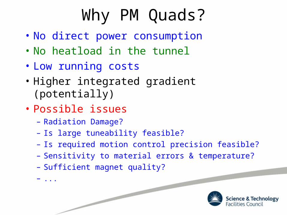
Why PM Quads?• No direct power consumption• No heatload in the tunnel• Low running costs• Higher integrated gradient (potentially)• Possible issues
– Radiation Damage?– Is large tuneability feasible?– Is required motion control precision feasible?– Sensitivity to material errors & temperature?– Sufficient magnet quality?– ...

Specification• Max Integrated gradient 14.6 T (120%
setting)• Inner radius of vac chamber 11.5 mm• Outer radius of vac chamber 13.0 mm• Field quality within ±0.1% over ±5.75 mm• Max dimensions of magnet:
– 391 x 391 x 270 mm (H x V x L)
• Adjustability of integrated gradient– 120% to ~60% at high energy– ~43% to 7% at low energy
• Need dipole correction also of 12 mTm (max) in both planes (not simultaneous)
Erik Adli

Tuneability
Low energy end more demanding in terms of adjustable range of magnet
Erik Adli & Daniel Siemaszko

Options Considered• Combination of PM and coils
– Use coils to adjust field
• Circular PM (Halbach) geometries– Use motion to adjust field
• Steel pole with PM excitation only– Use motion to adjust field

Assessment• Combination of PM and coils
– Little advantage over pure EM– Coils have to be of similar rating
• Circular PM geometries– Field quality poorer than other options
• Steel pole with PM excitation only– Best option, can meet spec

Many Geometries Assessed
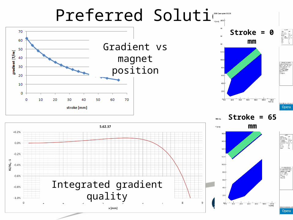
Preferred Solution
Integrated gradient quality
Gradient vs magnet position
Stroke = 0 mm
Stroke = 65 mm
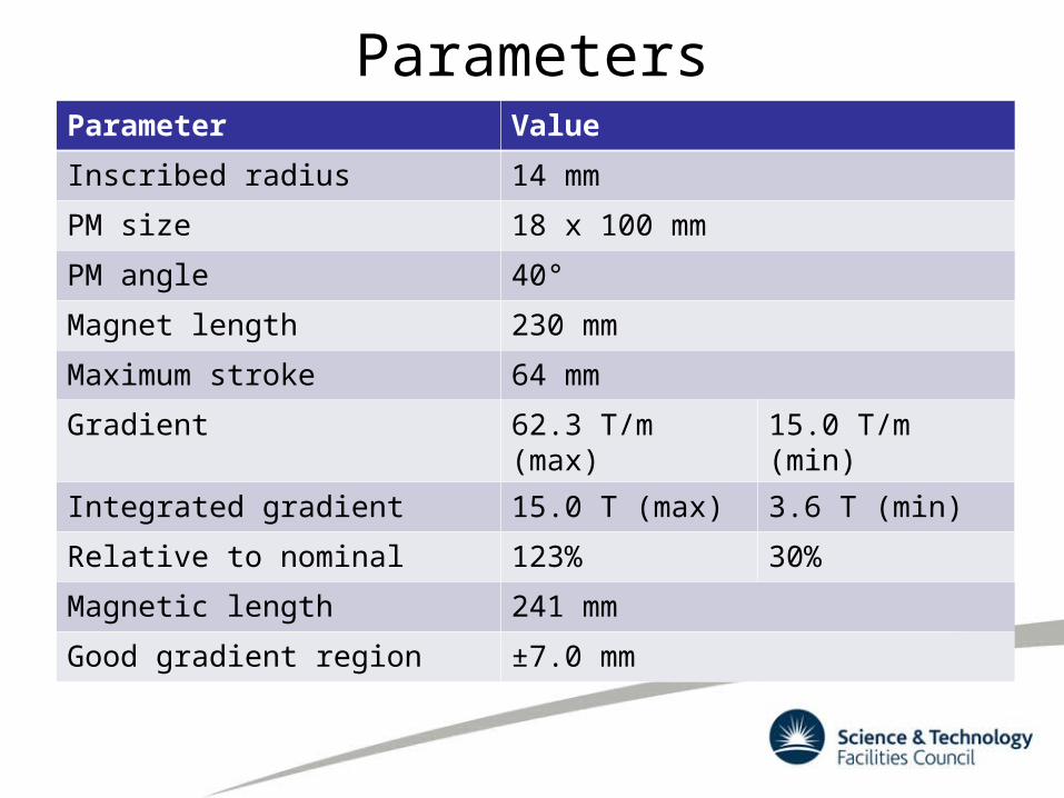
ParametersParameter Value
Inscribed radius 14 mm
PM size 18 x 100 mm
PM angle 40°
Magnet length 230 mm
Maximum stroke 64 mm
Gradient 62.3 T/m (max) 15.0 T/m (min)
Integrated gradient 15.0 T (max) 3.6 T (min)
Relative to nominal 123% 30%
Magnetic length 241 mm
Good gradient region ±7.0 mm

Basic Engineering Concept
Steel
Non-magnetic support
PM Block
Steel Pole
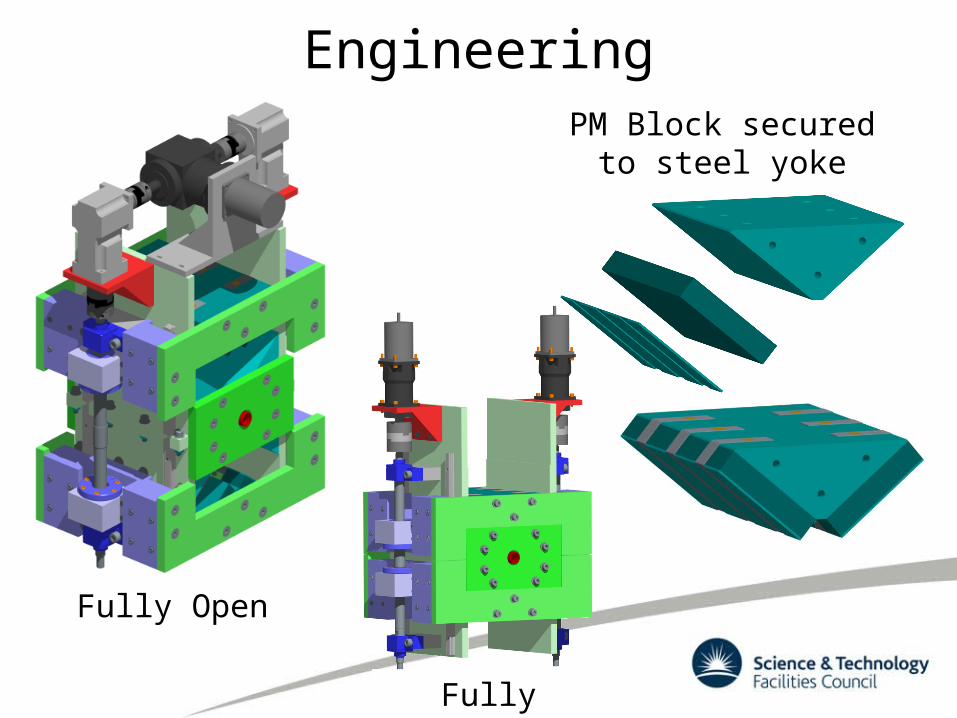
Engineering
Fully Open
Fully Closed
PM Block secured to steel yoke
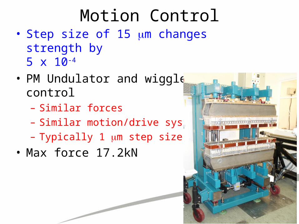
Motion Control• Step size of 15 m changes strength by
5 x 10⁻⁴ • PM Undulator and wiggler motion
control– Similar forces– Similar motion/drive system– Typically 1 m step size
• Max force 17.2kN

PM size tolerance study• Modelled complete magnet (not quadrant)
in 2D• Adjusted dimensions of one PM by 0.1mm;
measured relative effect on gradient• Same for PM length in 3D• Relative changes:
– 0.2%/mm for width (nominally 100mm)– 1.0%/mm for height (nominally 21mm)– 0.1%/mm for length (nominally 228mm)
• Length tolerance:~0.1% of each dimension
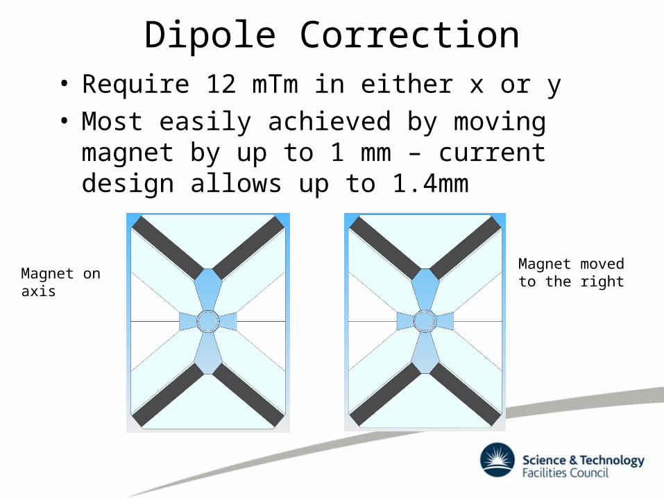
Dipole Correction• Require 12 mTm in either x or y• Most easily achieved by moving magnet
by up to 1 mm – current design allows up to 1.4mm
Magnet moved to the rightMagnet on axis

EMMA Quadrupoles• The quadrupoles in EMMA (nsFFAG) at Daresbury are
mounted on horizontal slides to provide independent control of the dipole term
• A similar arrangement could be used to provide CLIC drive beam steering

PM Quads in CLIC

Next Steps• Detailed engineering design• Assemble and test prototype• Assess impact of radiation damage• Assess thermal effects• Weaker versions for low energy drive
beam need to be designed and optimised– Will reoptimise design for greater tuneability
• Challenge of automation of production