permit to install workbook - michigan.gov€¦ · permit to install. workbook rev. 1/2016 air...
TRANSCRIPT

PERMIT TO INSTALL
WORKBOOK
Rev. 1/2016
Air Quality Division
Michigan Department of Environmental Quality Office of Environmental Assistance and Air Quality Division www.michigan.gov/deq ● 800-662-9278
A Practical Guide to Completing an Air Permit Application

This publication is intended for guidance only and may be impacted by changes in legislation, rules, policies, and procedures adopted after the date of publication. Although this publication makes every effort to teach users how to meet applicable compliance obligations, use of this publication does not constitute the rendering of legal advice.

TABLE OF CONTENTS PREFACE CHAPTER 1: Introduction to the Permit to Install Program
Introduction ......................................................................................................... 1-1 Air Pollution Regulatory Agencies ....................................................................... 1-1 Air Quality Division Organization ......................................................................... 1-2 Permit Resources ............................................................................................... 1-5 CHAPTER 2: Determining Applicability Do I Need a Permit to Install? ............................................................................. 2-1 Exemptions ......................................................................................................... 2-3 Frequently Asked Questions ............................................................................... 2-6 CHAPTER 3: Filling Out the Application Introduction ......................................................................................................... 3-1 Filling Out the Application.................................................................................... 3-2 Recommendations .............................................................................................. 3-6 CHAPTER 4: Important Terms Device ................................................................................................................. 4-1 Emission Unit ...................................................................................................... 4-1 Flexible Group ..................................................................................................... 4-6 Stationary Source ............................................................................................... 4-7 National Ambient Air Quality Standards .............................................................. 4-9 Air Contaminants .............................................................................................. 4-10 Emission Rates ................................................................................................. 4-11 Source Classification ......................................................................................... 4-13 CHAPTER 5: Additional Supporting Information Introduction ......................................................................................................... 5-1 Cover Letter ........................................................................................................ 5-3 Site Map .............................................................................................................. 5-5 Plant Layout Map ................................................................................................ 5-6 Emission Unit Description ................................................................................... 5-7 Process Flow Diagrams ...................................................................................... 5-9 Stack Descriptions/Parameters ........................................................................... 5-9 Emission Calculations ....................................................................................... 5-15 Regulatory Discussion ...................................................................................... 5-52 Air Toxics Regulations ...................................................................................... 5-66 Odor Issues....................................................................................................... 5-76 Air Quality Plans ............................................................................................... 5-77 Assembling Your Permit Application Submittal .................................................. 5-78 CHAPTER 6: Permitting Process Introduction ......................................................................................................... 6-1 Permit Screening ................................................................................................ 6-1 Preparing Application for Assignment.................................................................. 6-2 Permit Engineer’s Review ................................................................................... 6-2 Draft Permit Conditions ....................................................................................... 6-4 Public Notice ....................................................................................................... 6-4

Michigan’s Permit to Install Workbook CHAPTER 7: What a PTI Looks Like
Introduction ......................................................................................................... 7-1 Permit Condition Examples ................................................................................. 7-1 Permit Status on the Internet ............................................................................... 7-5 Approved Permit to Install ................................................................................... 7-6 CHAPTER 8: How to Comply with Your Permit to Install
What Companies Should Know ........................................................................... 8-1 Compliance with the Permit to Install .................................................................. 8-2 Compliance Monitoring ....................................................................................... 8-4 Modifications to the Permit to Install .................................................................... 8-8 CHAPTER 9: Miscellaneous Issues
Confidentiality ..................................................................................................... 9-1 Construction Waivers .......................................................................................... 9-2 Voiding a Permit to Install .................................................................................... 9-3 Change of Ownership ......................................................................................... 9-3 Tax Exemptions .................................................................................................. 9-4 Pollution Prevention Loan Program ..................................................................... 9-4 Environmental Audits .......................................................................................... 9-4 Clean Corporate Citizen Program ....................................................................... 9-6 Michigan Air Emissions Reporting System .......................................................... 9-7 APPENDIX A: Hazardous Air Pollutant (HAP) List APPENDIX B: List of Excluded Substances APPENDIX C: Michigan Air Toxics Rules APPENDIX D: Reference Table for Odors APPENDIX E: Solutions to Workbook Examples

PREFACE
The Michigan Department of Environmental Quality (MDEQ), Office of Environmental Assistance, in conjunction with the Air Quality Division of the MDEQ, developed this “Permit to Install Workbook – A Practical Guide to Completing an Air Permit Application.” The workbook is designed to help businesses obtain a Permit to Install for processes or activities that emit air contaminants; e.g., boilers, coating operations, and solvent degreasers. This workbook brings guidance material, instructions, and demonstrative examples via our mock company, Chromewell Plating, Inc., together into one practical and easy-to-use reference document. The workbook was not developed to help companies determine applicability of the Permit to Install requirement, but rather assumes that the user is subject to permitting requirements, and now seeks to develop an application package for submittal. Facilities that are interested in determining applicability are encouraged to contact the Office of Environmental Assistance at 800-662-9278 for a copy of the “Permit to Install – Determining Applicability Guidebook.” Furthermore, this workbook was not designed to provide detailed guidance for developing an Air Permit Application submittal if the project is subject to major source review requirements for attainment or nonattainment areas. However, major source applicability requirements are briefly discussed in the workbook; documents and other resources have been identified which can further explain these programs. The MDEQ invites those who expect to apply for a permit when “major source review requirements” may apply to contact the Air Quality Division’s Permit Section to arrange for pre-application discussions or meetings. Note: Throughout the workbook, the term “air permit” is used in a generic sense. You will not find a definition of this term in the state air quality regulations. The application for the air contaminant emitting process is referred to as the “Permit to Install Application.” The application must be submitted prior to the installation of the process. A “Permit to Install” is the term given to the approved permit. Once a Permit to Install has been issued, the facility may proceed with the installation. “New Source Review” is the regulatory activity associated with the evaluation of a major source’s compliance with the federal requirements for major sources in attainment and nonattainment areas and the subsequent issuance of a Permit to Install by the regulatory agencies.
For more information about calculating the Permit to Install process, including helpful process related information and other permit resources, visit the Air Quality Division’s Permits Web site: www.michigan.gov/air (select “Permits”).


CHAPTER 1
Introduction to the Michigan Department of Environmental Quality
Air Quality Division Permit to Install Program
In This Chapter:
• Introduction
• Air Pollution Regulatory Agencies
• Air Quality Division Organization
• Permit Resources


Michigan’s Permit to Install Workbook
Introduction 1-1
CHAPTER 1: Introduction to the Michigan Department of Environmental Quality Air Quality Division Permit to Install Program
Introduction
The State of Michigan passed the “Natural Resources and Environmental Protection Act,” Act 451 of 1994. Act 451, as amended, authorizes the Michigan Department of Environmental Quality (MDEQ), in part, to promulgate rules and establish standards for emissions and ambient air quality and to issue permits for the construction and operation of facilities subject to enforceable emission limitations and standards. A Permit to Install (PTI) is the legally enforceable document used to specify the emission limitations, standards and other regulatory requirements that apply to an individual facility. It authorizes a commercial/industrial entity to initiate the construction, installation, relocation, reconstruction, or modification of a process that emits air contaminants in agreement with the plans and specifications approved by the Air Quality Division (AQD) of the MDEQ. The purpose of this chapter is to describe the regulatory responsibilities of federal and state agencies and to further delineate responsibilities within the MDEQ regarding issuance of PTIs. Air Pollution Regulatory Agencies Direct or indirect releases of air contaminants into the outdoor environment are regulated by the U.S. Environmental Protection Agency (U.S. EPA) and the MDEQ. Both agencies have developed a program that protects the environment from adverse impacts that can affect human health, animal, or plant life. Rules and regulations have been promulgated through federal, state, and local legislation which give each agency the authority to administer their respective programs. U.S. EPA: The U.S. EPA was established as an independent agency in the Executive Branch of the U.S. Government in 1970. Congress gave the U.S. EPA responsibility for implementing an ambitious set of federal environmental laws, including the federal Clean Air Act. The U.S. EPA’s Office of Air and Radiation is responsible for overseeing the air activities of the agency, which include the development of national programs, technical policies, and regulations for air pollution control. Information about the U.S. EPA can be viewed and downloaded from its website at www3.epa.gov/air/ . MDEQ’s AQD: The AQD is located within the MDEQ. Through authority delegated from the U.S. EPA, the AQD enforces compliance with many federal air quality regulations promulgated under the federal Clean Air Act. The AQD is also responsible for enforcing compliance with state air quality rules. This is achieved through a number of activities such as permitting, air quality evaluation, compliance and enforcement, and evaluating air toxics. The Permit Section of the AQD is responsible for permitting all new and modified sources of air pollution in the State of Michigan. Michigan rules can be found in Part 55 of Act 451. Both the U.S. EPA and the MDEQ have authority over sources of air pollution in Michigan. The U.S. EPA has delegated its major source permitting authority in Michigan to the MDEQ. Under this arrangement, the MDEQ issues the permits and the U.S. EPA retains oversight, which includes reviewing the proposed permits while still in the draft stage. These permits are typically the more complex PTI applications. The U.S. EPA’s review of draft permits, prior to approval, is designed to

Michigan’s Permit to Install Workbook
1-2 Introduction
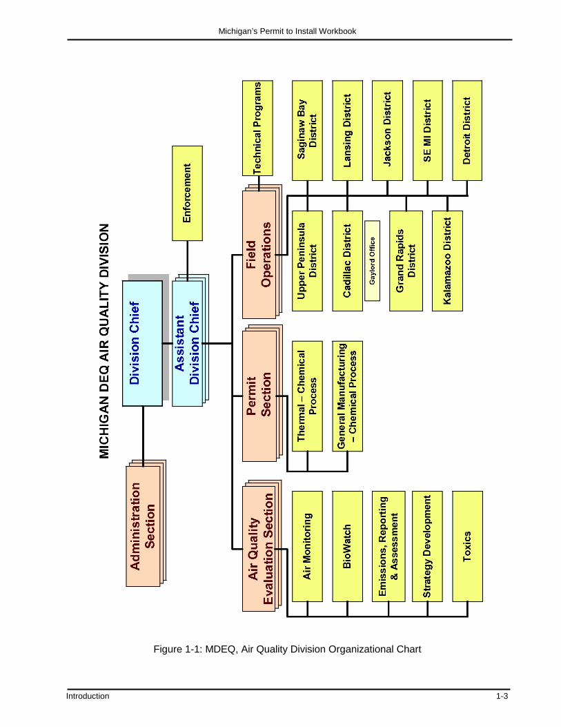
ensure that they are federally-enforceable and consistent with all state and federal requirements. The MDEQ also issues minor source permits under its minor source permitting program. Under federal law, the MDEQ is required to provide the public an opportunity to comment on draft major source permits. This opportunity is granted during a 30-day public notice period beginning once advertisement of the notice period has begun. Advertisement of the notice period appears on the MDEQ web page and in the newspaper(s) in the location of the new installation. During this time period, the U.S. EPA also provides its comments for MDEQ’s consideration. The type of PTI application reviews subject to this U.S. EPA oversight and/or public notice and comment requirements include synthetic minor applications and major source applications that are subject to federal programs (i.e., Prevention of Significant Deterioration, Major Offset Program, National Emission Standards for Hazardous Air Pollutants, and Renewable Operating Permit program). Minor and major sources are defined in Chapter 4. Air Quality Division Organization Figure 1-1 is an organizational chart of the AQD. It includes a brief listing of responsibilities of each section relative to PTI issuance and application review. Note that PTIs are issued in Lansing by the Permit Section. Air quality modeling and toxicology work associated with PTI application review are performed by the Air Quality Evaluation Section, also located in Lansing. District personnel in the Field Operations Section provide input to the Permit Section engineers regarding PTI conditions and recommendations. District staff also issue construction waivers, when appropriate, allowing construction of certain equipment prior to PTI issuance. Figure 1-2 identifies the location and telephone numbers of the eight AQD district offices and two field offices. Additional information about the AQD can be viewed and downloaded from its website at www.michigan.gov/air.
Michigan’s Permit to Install Workbook
Introduction 1-3
Figure 1-1: MDEQ, Air Quality Division Organizational Chart

Michigan’s Permit to Install Workbook
1-4 Introduction
Region 1 - Upper Peninsula District Office 1504 West Washington Street Marquette, MI 49855 Phone: 906-346-8300
Region 2 - Cadillac District Office 120 West Chapin St. Cadillac, MI 49601 Phone: 231-775-3960
Region 3 - Gaylord Field Office 2100 West M-32 Gaylord, MI 49735 Phone: 989-731-4920
Region 4 - Grand Rapids District Office 350 Ottawa Avenue, NW, Unit 10 Grand Rapids, MI 49503-2341 Phone: 616-356-0500
Regions 5 & 6 - Saginaw Bay District Office 401 Ketchum Street, Suite B Bay City, MI 48708 Phone: 989-894-6200
Region 7 - Lansing District Office Constitution Hall, 1st Floor South 525 West Allegan Street Lansing, MI 48933 Phone: 517-284-6651
Region 8 - Kalamazoo District Office 7953 Adobe Road Kalamazoo, MI 49009-5025 Phone: 269-567-3500
Region 9 - Jackson District Office 301 East Louis Glick Highway Jackson, MI 49201-1556 Phone: 517-780-7690
Region 10 - SE Michigan District Office 27700 Donald Court Warren, MI 48092-2793 Phone: 586-753-3700
Detroit Field Office Cadillac Place 3058 W. Grand Blvd., Ste. 2-300 Detroit, MI 48202 Phone: 313-456-4700
Figure 1-2: MDEQ, Air Quality Division District and Field Offices

Michigan’s Permit to Install Workbook
Introduction 1-5
Permit Resources
Many references to guidance documents, forms, and other helpful tools used in completing a Permit to Install application are made throughout this workbook. Below is a summary of the agencies that provide these resources, as well as some additional resources that you may find valuable.
MDEQ
Are you looking for a copy of the Permit to Install application form, General Permit to Install form, additional instructions, or permit guidance documents? Do you have questions about the receipt and assignment of your application? If so, go to the AQD website at www.michigan.gov/air. You can also contact the Office of Environmental Assistance (OEA) at 800-662-9278, or the Permit Section of the AQD at 517-284-6804 to obtain a hard copy of the application.
U.S. EPA
The U.S. EPA’s website contains a wealth of information pertaining to federal air quality regulations, guidance documents, and the calculation of air emissions. The U.S. EPA’s home page is www.epa.gov. The Office of Air Quality Planning and Standards’ (OAQPS) website contains information pertaining to emission standards for a wide variety of industrial sources. Its website is www3.epa.gov/airquality/. From the OAQPS website, or by going directly to www.epa.gov/ttn, you can access the Technology Transfer Network (TTN). The TTN is a collection of technical websites containing information about many areas of air pollution science, technology, regulation, measurement, and prevention. One such website is the ClearingHouse for Inventories and Emission Factors (CHIEF), which contains the latest information on emission factors. Emission factors are used to quantify the emission of air contaminants from various processes, and are an important part of your Permit to Install application submittal.
OEA
The OEA is designed to help companies with fewer than 100 employees understand and comply with federal and state regulations that protect our air. Through telephone consultations, guidance publications, and specific workshops, OEA helps small and medium-sized businesses understand their obligations under state and federal air quality regulations and identify ways to comply with those requirements. The OEA’s “Permit to Install – Determining Applicability Guidebook” answers many questions facilities have regarding whether or not they need to apply for an air permit. Included in the publication are definitions of, and flowcharts outlining the use of the terms that trigger the need for a permit: installation, construction, reconstruction, relocation, and modification. For help with permit applicability and completion of applications, or to request guidance documents, contact the OEA at 800-662-9278 or visit its website at www.michigan.gov/air (select “Compliance” then “Clean Air Assistance”).

Michigan’s Permit to Install Workbook
1-6 Introduction
Michigan Economic Development Corporation The Michigan Economic Development Corporation’s Clean Air Ombudsman acts as a liaison between the MDEQ’s AQD and small business owners and managers. The services provided by the Clean Air Ombudsman include:
• Assistance with understanding air quality regulations and compliance issues. • Mediation in resolving complaints or disputes. • Representation of small business concerns during new air quality rule development.
Call 888-522-0103 or access the Michigan Economic Development Corporation’s website at www.michiganbusiness.org for more information.

CHAPTER 2
Determining Applicability
In This Chapter:
• Do I Need a Permit To Install? • Exemptions
o Grandfathered Sources o Exemptions Provided under Rules 278 – 290 o Activity Time-frame
• Frequently Asked Questions


Michigan’s Permit to Install Workbook
Determining Applicability 2-1
CHAPTER 2: Determining Applicability
Do I Need a Permit To Install? Is your business planning a project that involves installing, constructing, reconstructing, relocating, or modifying any process or process equipment that emits, or may emit, air contaminants (e.g., spray paint booth, storage tank, printing line, boiler, grinder and dust collector, plating operation, degreaser)? If so, your facility may need to apply for a "Permit to Install,” commonly referred to as an air permit. The project you are planning to undertake must be evaluated to determine if a Permit to Install is required under R336.1201 (Rule 201). Rule 201 of the Michigan Air Pollution Control Rules specifies that:
A person shall not install, construct, reconstruct, relocate, or modify any process or process equipment, including control equipment pertaining thereto, which may emit [an air contaminant], unless a Permit to Install which authorizes such action is issued by the Department.
To determine if a Permit to Install is required, the project must first be defined. To properly define the project, a clear understanding of the five terms from Rule 201 is needed. These five terms are more commonly referred to as “activities.” The project will consist of one or more of these activities. The term “activity” means the concurrent and related installation, construction, relocation, or modification of any process or process equipment. Some brief definitions of these terms follow. The terms “installation” and “construction” are often used interchangeably and generally pertain to the installation of new emission units, e.g. installing a third boiler in an existing powerhouse or breaking ground for a new business that will include equipment that will emit air contaminants. These two terms, installation and construction, basically mean the same thing. However, it is important to understand the subtle differences between the two terms. “Installation” means installing new emission units into an existing building or an existing site, whereas “construction” means constructing a new building along with installing new emission units within the building or installing emission units at a new site. For example, if a new emission unit is installed into an existing building, then that activity is considered “installing” an emission unit. If the installation requires breaking ground for a new building that will house an emission unit, then that activity is considered “constructing” an emission unit. The distinction between installation and construction will affect when a Permit to Install must be obtained by the facility. If the project consists of installing a new emission unit, the facility is required to obtain an approved Permit to Install before installation begins. If the project consists of constructing an emission unit, the facility must acquire the approved Permit to Install prior to pouring the foundations of the new building that will house the new emission unit. Many companies make the mistake of breaking ground for a building that will house an emission unit before getting a Permit to Install. This may be a violation of Michigan Rule 201. “Reconstruction” is simply the one-for-one replacement of the components of an emission unit (e.g., replace a fan with a fan, replace piping with piping). However, not all replacements of components require a Permit to Install. According to Michigan Rule 118(b), the definition of

Michigan’s Permit to Install Workbook
2-2 Determining Applicability
reconstruction is the replacement of components of an existing emission unit so that the fixed capital cost of the new components is more than 50 percent of the fixed capital cost that would be required to construct a comparable, entirely new emission unit. The minor replacement of components is not considered a reconstruction and, therefore, can take place without a permit. “Relocation” is moving an existing emission unit. Relocation may occur within the same facility or from one facility to another. For example, instead of operating a degreaser in one section of its plant, a company moves it to another section of the plant. Relocation does not include any activities that will change the emission rate of air contaminants from the emission unit, or the exhaust stack parameters from which its emissions are released to the outdoor air. Relocation is simply picking up the emission unit and moving it to a new spot within the same facility. If changes in the emissions (or stack parameters) occur concurrently with the move, then this may be considered a modification. An emission unit moved to a different facility is considered an installation.
XYZ Company
123 N. Main Street 456 Elm Street
Relocation (Requiring a Permit to Install)
Relocation (Not Requiring a Permit to Install)
EU1 EU2
EU3
EU4
XYZ Company

Michigan’s Permit to Install Workbook
Determining Applicability 2-3
The term “modification” (or modify) is defined in Michigan Rule 113(j). According to this rule, the modification of an emission unit is the physical or operational change to an existing emission unit that results in one or more of the following:
(a) increased emissions; (b) emissions of new pollutants not previously permitted; or (c) changes to other existing permit conditions. Some physical and operational changes that may qualify as a modification include: substituting new raw materials such as coatings or fuels; increasing the hours of operation over previously permitted levels; or increasing the capacity of the emission unit, such as adding additional spray guns to a coating booth. Other Activities that Require Permits There are activities that warrant an approved PTI even though they do not fit under the definition of installation/construction, reconstruction, relocation, or modification. These activities include the following:
• Obtaining enforceable limitations to restrict a source’s potential to emit to below the applicable major source thresholds in order to avoid the applicability of the renewable operating permit (ROP) program.
• Consolidating terms and conditions from existing PTIs within a ROP.
• Replacing or removing special conditions of an approved Permit to Install. Note that Rule 201 does not state that an air contaminant has to be released, but that it may be possible to release an air contaminant. ("Air contaminants" are classified as dust, fume, gas, mist, odor, smoke, vapor, or any combinations thereof that are suspended air borne particles in the outdoor environment. A more detailed explanation of the term “air contaminant” is found in Chapter 4.) However, not everything that emits or may emit an air contaminant needs an air permit. The Michigan Air Pollution Control Rules contain a number of exemptions that should be consulted. In summary, just about any project requires a Permit to Install unless it can be specifically exempted or demonstrate that it does not have the potential to emit an air contaminant. The Office of Environmental Assistance “Permit to Install – Determining Applicability Guidebook” answers many questions facilities have regarding whether or not they need to apply for an air permit. Included in the publication are definitions of, and flowcharts outlining the use of the terms that trigger the need for a permit: installation, construction, reconstruction, relocation, and modification. This publication can be accessed at www.michigan.gov/air (select “Permits” then “Permits to Install/New Source Review (PTI/NSR)” then “Application Form, Instructions and Guidance Documents”). Exemptions Grandfathered Sources Existing processes that emit air contaminants and were installed before August 15, 1967, are not required to apply for a Permit to Install unless the equipment or production processes are proposed to be, or have been, modified after that date. August 15, 1967, is the date the Michigan Air Pollution Control Rules first took effect. There are very few “grandfathered" processes in existence since most facilities have, throughout the years, made changes or modifications that require a permit.

Michigan’s Permit to Install Workbook
2-4 Determining Applicability
Exemptions Provided Under Rules 278 - 290 Rule 278 (Exception to the Use of Exemptions) Rule 278 serves as an initial screening for proposed projects involving any of the five “activities” described above: installation, construction, reconstruction, relocation, or modification of air emitting equipment. If the proposed project meets the Rule 278 criteria, the facility can not utilize the permit exemptions found in Rules 280 through 290. Rule 278 precludes the use of exemptions from a Permit to Install for “major sources” and “major modifications” as defined under: (1) Federal Prevention of Significant Deterioration regulations, (2) Major source review requirements for nonattainment areas, or (3) National Emission Standards for Hazardous Air Pollutants. In addition, Rule 278 precludes the use of exemptions if the actual emissions of any criteria air pollutant from the proposed activity exceed one or more of the following: Carbon monoxide - 100 tons per year Nitrogen oxides - 40 tons per year Sulfur dioxide - 40 tons per year Particulate matter (TSP) - 25 tons per year Particulate less than10 microns (PM-10) - 15 tons per year Volatile organic compounds - 40 tons per year Lead - 0.6 tons per year For example, Rule 285(g) exempts from the PTI requirement (Michigan Rule 201), internal combustion engines that have less than 10,000,000 Btu/hour maximum heat input. Most of these engines operate on an emergency basis, i.e., a couple of hundred hours per year. However, if a company plans on running the engine around the clock, the emissions of nitrogen oxide could very well exceed the significant levels. Rule 278 excludes the use of the exemptions specified in Rules 280-290 if the emissions will be significant. In this case, the company would not use Rule 285(g) and would therefore need to apply for a PTI. If an emission unit activity is covered by an exemption, then Rule 278a requirements apply. Rule 278a requires that the owner of an exempt emission unit must be able to provide information demonstrating the applicability of the exemption. The demonstration must be provided within 30 days of a written request from the MDEQ. The demonstration may include the following information:
• A description of the exempt process or process equipment, including the date of installation. • The specific exemption being used by the process or process equipment. • An analysis demonstrating that Rule 278 does not apply to the emission unit. • The records that have been kept as required by a specific exemption.
For information on how to determine whether your proposed installation is a major source or major modification, refer to the “Permit to Install – Determining Applicability Guidebook.” This publication can be accessed at www.michigan.gov/air (select “select “Permits” then “Permits to Install/New Source Review (PTI/NSR)” then “Application Form, Instructions and Guidance Documents”). Chapter 5 of this publication contains a discussion of the terms “major source” and “major modification.”

Michigan’s Permit to Install Workbook
Determining Applicability 2-5
Rules 280 – 290 Provided that the proposed activity is not precluded by Rule 278 from utilizing permit exemptions, you can look for an appropriate exemption for your process in Rules 280 through 290. If the process appears to be in one of the exempt categories, the actual rules should be consulted to identify whether there is, in fact, a potential exemption. DO NOT rely on the rule heading to identify if a process is exempt; instead, read the entire rule before making a decision. The most current listing of exemptions should be used for any decisions made about whether a Permit to Install is required. Examples of the broad categories where certain specific exemptions may be found are:
• Rule 280 – Cooling and ventilating equipment • Rule 281 – Cleaning, washing, and drying equipment • Rule 282 – Furnaces, ovens, and heaters • Rule 283 – Testing and inspection equipment • Rule 284 – Containers • Rule 285 – Miscellaneous minor parts replacement or repairs, and other miscellaneous operations • Rule 286 – Plastic processing equipment Rule 287 – Surface coating equipment Rule 288 – Oil and gas processing equipment Rule 289 – Asphalt and concrete production equipment Rule 290 – Emission Units with limited emissions
The rules must be read carefully to determine if an activity really falls under an exemption category. If you determine that an activity is exempt, keep a written record of how you arrived at that decision. If an activity is exempt, there is no need to notify the regulatory agencies about the activity. Note, however, that a source is still subject to other applicable state and federal air quality rules, such as those regarding air emission nuisances, even if it is exempt. Also pay attention to the exemptions since many of them carry record keeping requirements. A failure to maintain the necessary records will disqualify your use of the exemption and a Permit to Install will be required. Sham Permitting The definition of the activity is critical to a successful evaluation of Rule 278. The more emission unit activities that the company has under one activity, the more emissions the activity emits, which increases the chances of the company meeting one of the criteria in Rule 278. Facilities must not stage construction, i.e., break one activity into two or more activities, to avoid meeting the criteria in Rule 278. This is considered a violation of Michigan Rule 278 and referred to as “sham permitting.” The criteria in Rule 278 must be applied to the entire activity, not individual phases of the activity. For example, if a facility plans to install three boilers during a two-year period, the aggregate emissions from the three boilers (not the individual emissions from each boiler) are considered when taking the Rule 278 test. Staging construction to avoid the criteria in Rule 278 may also violate the major source review requirements for Prevention of Significant Deterioration (PSD) or for nonattainment areas. This would be a violation of federal law. In addition to the OEA, air quality staff in the MDEQ district offices can help interpret the rules (see Chapter 1 Figure 1-2 for phone numbers). To help determine if your air contaminant emitting process is exempt, refer to the exemption sections (Rules 278-290) of the Michigan Air Pollution Control Rules or contact your district office. A copy of the rules may be obtained at www.michigan.gov/air (select “News and Info” then “State Air Laws and Rules” then “Part 2 Exemptions, Rules 278-290).

Michigan’s Permit to Install Workbook
2-6 Determining Applicability
Activity Time Frame In most cases, the activity will consist of the installation of one new emission unit or the modification of an existing emission unit. However, there may be times, especially for larger facilities, where there will be activities that affect multiple emission units occurring concurrently or sequentially; i.e., phased in over time. For activities involving multiple emission units, the time period that is used to define the activity becomes very important. There are no hard and fast rules for determining the timeframe of an activity. Activities can affect emission units and can occur within a month, a year, or several years. If there are multiple installations and modifications of emission units at the same time, all of those should be considered part of the same activity. If the emission unit installations are occurring sequentially or in phases, then it is more difficult to define the activity. In this case, the following rule of thumb may be useful: the collection of emission units that make up the activity should be the same collection of emission units that are brought before the company’s board of directors for approval. For example, the facility plans to install a new coating line. The coating line will increase the demand of power from the powerhouse. Therefore, the boiler will need to be modified within six months of installing the coating line. When going to the board for approval of this activity, the request would include both the new installation of the coating line as well as the modification to the powerhouse. The request presentation would include both of the activities to the board. Therefore, the activity would consist of one installation of a new emission unit and one modification on an existing emission unit. Frequently Asked Questions Do I need to contact the Air Quality Division if my emission unit is covered under an exemption? If your emission unit activity (i.e., installation/construction, relocation, reconstruction, or modification) is covered under an exemption, you do not have to provide any notification to the Air Quality Division (AQD). However, in cases where there may be an interpretation issue, it is always a good idea to contact either the Clean Air Assistance Program or the district office of the AQD for verification. Be aware that some of the exemptions do require you to comply with specific requirements in order to use the exemptions. For example, Michigan Rule 287(c) requires recordkeeping and operation of a particulate control system on any exhaust system. If my emission unit is exempt from the Permit to Install requirements, are there other air quality rules that apply? Even though an emission unit may be exempt from Michigan Rule 201, that emission unit still needs to comply with all applicable state and/or federal rules. For example, although Michigan Rules exempt certain cold cleaners from having to obtain a Permit to Install, the facility may need to comply with Michigan Rule 707 which pertains to the proper operation of cold cleaners. Michigan Rule 282(b)(i) exempts sweet natural gas-fired boilers that have a rated heat input capacity of not more than 50,000,000 Btu per hour from the Permit to Install requirement; however, the boilers may still be subject to the federal New Source Performance Standard (NSPS), Subpart Dc.

Michigan’s Permit to Install Workbook
Determining Applicability 2-7
Are the permit exemptions retroactive? Yes, they are. They apply to all emission units, regardless of when they were first installed. For example, if you have a permit for a coating line that was installed in 1987 but it is now exempt under Michigan Rule 287(c), you can request that the permit be voided. Conversely, if you were supposed to get a permit for your coating line when it was installed in 1987 but it is now covered under an exemption, you do not need to apply for a Permit to Install. Can more than one permit exemption apply to my emission unit? Yes, they can. Exemptions are applied at either the process device or emission unit level. Some exemptions may apply to individual process devices within an emission unit whereas some exemptions may apply to multiple devices within an emission unit. The following two examples illustrate this point.
Example 1: A company operates a reaction injection molding machine that injects a coating into the mold. This emission unit has two different process devices: plastic injection molding and coating. Two permit exemptions may be applied to the one emission unit provided that the emission unit does not meet any of the criteria in Michigan Rule 278. Michigan Rule 286(e) exempts reaction injection molding, and Rule 287(c) exempts surface coating lines that use less than 200 gallons a month from the Permit to Install requirement. Example 2: A company operates a coating line containing two individual booths: prime coat and top coat. The emission unit contains both booths because there is a dependency between these two process devices. Michigan Rule 287(c) is an exemption for surface coating lines; therefore, the exemption must be applied at the emission unit level, not the process device level. To properly use the exemption, the total paint usage from both booths must be less than 200 gallons per month, not 200 gallons from the prime coat booth and another 200 gallons from the top coat booth.
Does transfer of ownership or change in a company name require the submittal of new permit applications? No. The terms and conditions automatically apply to the new owner or operator. If a permit applicant voluntarily elects to have their permit officially amended to reflect the change in ownership, Michigan Rule 219 explains the procedures that must be followed. The new owner must submit a letter (that contains the following information) to the appropriate AQD district office supervisor:
• Description of the source and emission units • Identification of the new owner • Written agreement between the current and new owner • Written statement by the new owner that the conditions of the permits are understood and
accepted The AQD has 60 days to respond to the request. Companies may also send a letter to the district office supervisor explaining any company name changes. The AQD will place copies of the letter into the appropriate files and make the necessary corrections to the appropriate internal databases.

Michigan’s Permit to Install Workbook
2-8 Determining Applicability
NOTES
CHAPTER 3:
Filling Out the Application
In This Chapter:
• Introduction
• Filling Out the Application
• Recommendations


Filling Out the Application 3-1
CHAPTER 3: Filling Out the Application Introduction The completion of a Permit to Install (PTI) application can be divided into two distinct activities: completing the one-page application form (EQP 5615E, Revised 09/2015) and gathering all of the supporting data listed on the back of the application form. In this chapter, we will explain how to fill out the application form. That is the easy part. Chapter 5 contains guidance on how to gather and assemble all of the supporting documentation. That is the more difficult part of preparing the application submittal. How Many Applications Should You Use? PTI applications can be submitted for a variety of reasons: construction of a brand new facility (like our mock company, Chromewell Plating Inc.); installation of new emission units; or the modification, relocation, or reconstruction of existing emission units at a facility. You can fill out an application for each individual emission unit you are proposing to install, or you may include all emission units under one application form. It is increasingly becoming the trend to issue facility-wide permits. If you include multiple emission units under one PTI application form, make sure you segregate the supporting information by emission unit. Where to Get an Application The application form is available at the AQD’s permit website www.deq.state.mi.us/aps. To schedule a pre-application meeting prior to submitting the application, the Applicant should contact the appropriate Unit Supervisor in the AQD Permit Section by calling 517-284-6811.

Michigan’s Permit to Install Workbook
3-2 Filling Out the Application
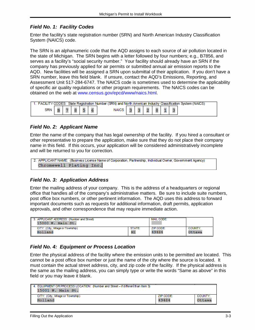
Filling Out the Application After receiving your PTI application form (Figure 3-1), carefully read the entire form before filling in the required information. If you are working with a hard copy, you may want to make a photocopy of the form to avoid making any major mistakes on the original. After you have compiled the information onto the copy in the appropriate manner, transfer that information onto the original application form. Let us go through the application field by field.
Figure 3-1: The Permit to Install Application
Michigan’s Permit to Install Workbook
Filling Out the Application 3-3
Field No. 1: Facility Codes Enter the facility’s state registration number (SRN) and North American Industry Classification System (NAICS) code. The SRN is an alphanumeric code that the AQD assigns to each source of air pollution located in the state of Michigan. The SRN begins with a letter followed by four numbers; e.g., B7856, and serves as a facility’s “social security number.” Your facility should already have an SRN if the company has previously applied for air permits or submitted annual air emission reports to the AQD. New facilities will be assigned a SRN upon submittal of their application. If you don’t have a SRN number, leave this field blank. If unsure, contact the AQD’s Emissions, Reporting, and Assessment Unit 517-284-6747. The NAICS code is sometimes used to determine the applicability of specific air quality regulations or other program requirements. The NAICS codes can be obtained on the web at www.census.gov/epcd/www/naics.html.
Field No. 2: Applicant Name Enter the name of the company that has legal ownership of the facility. If you hired a consultant or other representative to prepare the application, make sure that they do not place their company name in this field. If this occurs, your application will be considered administratively incomplete and will be returned to you for correction.
Field No. 3: Application Address Enter the mailing address of your company. This is the address of a headquarters or regional office that handles all of the company’s administrative matters. Be sure to include suite numbers, post office box numbers, or other pertinent information. The AQD uses this address to forward important documents such as requests for additional information, draft permits, application approvals, and other correspondence that may require immediate action.
Field No. 4: Equipment or Process Location Enter the physical address of the facility where the emission units to be permitted are located. This cannot be a post office box number or just the name of the city where the source is located. It must contain the actual street address, city, and zip code of the facility. If the physical address is the same as the mailing address, you can simply type or write the words “Same as above” in this field or you may leave it blank.

Michigan’s Permit to Install Workbook
3-4 Filling Out the Application
Field No. 5: General Nature of Business Enter a brief description of the general nature of the business. The key words are “brief description.” The description should not require more than a sentence to explain what the business does. It is a statement about the scope or purpose of the facility. It’s very important to look at all of the functions at the facility and determine the primary product or service that the facility offers. This information helps the AQD Permit Engineer reviewing the application to determine the applicable rules for the emission units.
Field No. 6: Equipment or Process Description Enter a clear explanation of the purpose for the application. The majority of application submittals fall under one or more of the following:
Construction of a new facility having one or more emission units. Installation of a new emission unit at an existing facility. Reconstruction, modification, or relocation of an existing emission unit. Revision of the special conditions of an existing Permit to Install. Limiting the facility’s potential to emit to below applicable major source thresholds.
Do not simply type the words “see attached” in Field No. 6 and then attach the whole equipment description on a separate piece of paper. You must provide at least part of the equipment description in this field. You can attach an additional sheet for the remaining description. It is important that your complete description include a list of exempt emission units that may be part of the project, but not part of the permit application submittal. PTI exemptions are discussed in Chapter 2.
Note: This sample application also includes the source classification codes (SCC) for the various processes identified (e.g., 4-02-025-02). An SCC is a numbering system devised by the U.S. Environmental Protection Agency (U.S. EPA) consisting of eight digits to identify many of the various air polluting activities in which your emission unit may be involved. Almost all SCCs have emission factors linked to the. This is very important because emission factors help you calculate emissions from your emission units. The calculation of air emissions is covered in Chapter 5. You can find an SCC and associated emission factors using the U.S. EPA’s WebFIRE application http://cfpub.epa.gov/webfire/.

Michigan’s Permit to Install Workbook
Filling Out the Application 3-5
Field No. 7: Reason for Application Select the type of permitting action that you are seeking; (i.e., installation/construction, reconstruction, modification or relocation). It is important to identify this information because the types of technical review to which the application will be subject depend, in part, on the type of permitting action being sought.
According to Rule 201 of the Michigan Air Pollution Control Rules, you should not be installing, reconstructing, modifying, or relocating emission units until you receive an approved PTI. It is in your best interest to allow several months for the processing and approval of your PTI. Field No. 8: Existing PTI If you are relocating, reconstructing, or modifying an existing emission unit that has a previously issued PTI, please record the permit number in Field No. 8. This helps ensure that the proper numbering sequence of permits is maintained. For example, the owner of an asphalt plant is submitting an application for the relocation of an existing plant. The current Permit to Install is identified as 232-98F. The company should enter this permit number in Field No. 8. The new PTI will be identified as 232-98G.
Field No. 9: Existing ROP If you are applying to add equipment or modify existing equipment at a facility that has a Renewable Operating Permit (ROP) or that has submitted an application for an ROP, mark the appropriate box in Field No. 9. Be sure to include the ROP number or application number if applicable. Permit applications for equipment at existing ROP sources may require additional administrative procedures prior to issuance, or prior to operation of the permitted equipment – even after issuance. The impact of these requirements can successfully be minimized if it is known that they apply. Therefore, accurately completing this field is very important.
Field Nos. 10 through 12: Authorized Employee/Contact Person Field 10 requires the signature of an authorized employee. The authorized employee’s signature must be original, not photocopied. Be aware that the application will be returned to you if it is not signed, or if the individual who signs the permit application does not meet the established criteria. Applications that are returned may be re-submitted, but this could result in costly delays in the permit approval and construction of the project. Fields 11 and 12 allow you to designate a contact person who will act as a liaison between your company and the AQD Permit Engineer reviewing the application. The contact person should have enough knowledge about the facility to answer questions that may arise during the technical review of the application. While the authorized employee must be an employee or official of the

Michigan’s Permit to Install Workbook
3-6 Filling Out the Application
company, you may choose to hire a consultant or other agent as your contact person. If you wish to authorize the contact person to negotiate permit terms and conditions, you can check the appropriate box in Field No. 12.
Disposition of Application The bottom portion of the application is used by the AQD to record the date when the Permit Engineer has determined that the application is technically complete (i.e., the application contains all of the necessary information to complete the evaluation of the application). The AQD also uses this field to record other important dates concerning actions taken by the Department of Environmental Quality. These actions include the date the PTI is approved, voided, or denied.
Recommendations It is recommended that you include a cover letter with the PTI application, providing further information regarding your application. Additional information regarding the purpose and content of a cover letter can be found in Chapter 5. This letter can also include a request for a construction waiver (see Chapter 9 for an explanation of construction waiver), if desired. Once you have completed filling out Field Nos. 1 through 12 of the PTI application, turn the application over. On the backside of the form is a list of additional information that must be attached to the form. Chapter 5 contains a discussion of all the supporting information that must be included in the application submittal.
Tex Mills
CHAPTER 4
Important Terms
In this Chapter:
• Device
• Emission Unit o Emission Unit Examples
• Flexible Group o Why Are Emissions Units Important to Air Permitting?
• Stationary Source
• National Ambient Air Quality Standards
• Air Contaminants
• Emission Rates o Potential to Emit
• Source Classification o Major Sources o Minor Sources
• Major Source Regulations o Major Source Review for Attainment Areas and Nonattainment Areas o Section 112(g) of the Federal Clean Air Act o Renewable Operating Permit

Michigan’s Permit to Install Workbook
Important Terms 4-1
CHAPTER 4: Important Terms
One key to submitting an administratively complete Permit to Install application form is to have a good understanding of basic terms. Some of the important terms used frequently in air permitting or new source review are the following:
• Device • Source • Attainment/Non-Attainment • Emission Unit • Air Contaminants • Emission Rates • Flexible Group • NAAQS • Major Source
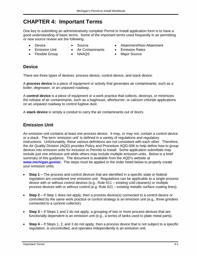
Device There are three types of devices: process device, control device, and stack device. A process device is a piece of equipment or activity that generates air contaminants, such as a boiler, degreaser, or an unpaved roadway. A control device is a piece of equipment or a work practice that collects, destroys, or minimizes the release of air contaminants, such as a baghouse, afterburner, or calcium chloride applications on an unpaved roadway to control fugitive dust. A stack device is simply a conduit to carry the air contaminants out of doors. Emission Unit An emission unit contains at least one process device. It may, or may not, contain a control device or a stack. The term ‘emission unit’ is defined in a variety of regulations and regulatory instructions. Unfortunately, these various definitions are not consistent with each other. Therefore, the Air Quality Division (AQD) provides Policy and Procedure AQD-006 to help define how to group devices into emission units for inclusion in Permits to Install. Some application submittals may include just one emission unit while others may include multiple emission units. Below is a brief summary of this guidance. The document is available from the AQD’s website at www.michigan.gov/air. The steps must be applied in the order listed below to properly create your emission units. • Step 1 – The process and control devices that are identified in a specific state or federal
regulation are considered one emission unit. Regulations can be applicable to a single process device with or without control devices (e.g., Rule 611 – existing cold cleaners) or multiple process devices with or without control (e.g. Rule 621 – existing metallic surface coating lines).
• Step 2 – If Step 1 does not apply, then a process device(s) connected to a control device or
controlled by the same work practice or control strategy is an emission unit (e.g., three grinders connected to a cyclone collector).
• Step 3 – If Steps 1 and 2 do not apply, a grouping of two or more process devices that are
functionally dependent is an emission unit (e.g., a series of tanks used to plate metal parts). • Step 4 – If Steps 1, 2, and 3 do not apply, then a process device that is not subject to a specific
regulation, is uncontrolled, and operates independently is an emission unit.

Michigan’s Permit to Install Workbook
4-2 Important Terms
Emission Unit Examples To help clarify the concept of emission units, let’s go through a couple of examples: Example 1: A facility is proposing to install a vapor degreaser unit that uses 1,1,1 - trichloroethane as the degreasing solvent. The vapor degreaser vents to the plant environment (i.e., there are no exhaust stacks associated with the unit).
Figure 4-1: Example One
The vapor degreaser, by itself, will be considered an emission unit because of the criteria listed under Step 1 above. The equipment is identified in a federal regulation, known as a National Emission Standard for Hazardous Air Pollutants (NESHAP) under 40 CFR Part 63 Subpart T. This standard regulates vapor degreasers that use certain chlorinated solvents, and 111- trichloroethane is one of the regulated solvents listed in the regulation. Notice that this emission unit contains one process device (see Figure 4-1). Emission units are defined as having at least one process device and may, or may not, contain a control device or a stack.
Emission Unit
1,1,1 – Trichloroethane Vapor Degreaser
Michigan’s Permit to Install Workbook
Important Terms 4-3
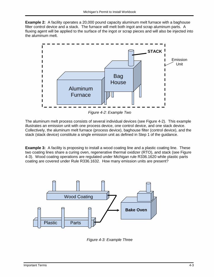
Example 2: A facility operates a 20,000 pound capacity aluminum melt furnace with a baghouse filter control device and a stack. The furnace will melt both ingot and scrap aluminum parts. A fluxing agent will be applied to the surface of the ingot or scrap pieces and will also be injected into the aluminum melt.
Figure 4-2: Example Two The aluminum melt process consists of several individual devices (see Figure 4-2). This example illustrates an emission unit with one process device, one control device, and one stack device. Collectively, the aluminum melt furnace (process device), baghouse filter (control device), and the stack (stack device) constitute a single emission unit as defined in Step 1 of the guidance. Example 3: A facility is proposing to install a wood coating line and a plastic coating line. These two coating lines share a curing oven, regenerative thermal oxidizer (RTO), and stack (see Figure 4-3). Wood coating operations are regulated under Michigan rule R336.1620 while plastic parts coating are covered under Rule R336.1632. How many emission units are present?
Figure 4-3: Example Three
STACK
RTO
Bake Oven
Wood Coating
Plastic Parts
Emission Unit
Bag House
Aluminum Furnace

Michigan’s Permit to Install Workbook
4-4 Important Terms
There are two emission units. Since there is a different state rule that applies to each coating line, each one is its own emission unit (see Step 1 above). The definition of “coating line” in the regulations includes applicators, flash-off areas, drying areas, and ovens. Figure 4-4a shows that one emission unit consists of the wood coating line, the bake oven, the regenerative thermal oxidizer (RTO) and all related stacks. The other emission unit, displayed in Figure 4-4b, consists of the plastic coating line, the bake oven, the RTO, and all related stacks.
Figure 4-4a. The First Emission Unit from Example Three
Figure 4-4b. The Second Emission Unit from Example Three
Example 4: A facility is proposing to install two boilers that share an electrostatic precipitator and an exhaust stack (see Figure 4-5). Each boiler is subject to a federal New Source Performance Standard (NSPS). How many emission units are present in this example?
Electrostatic Precipitator
Boiler No. 2 Boiler
No. 1
Emission Unit
Emission Unit
Figure 4-5: Example Four

Michigan’s Permit to Install Workbook
Important Terms 4-5
Again, there are two emission units. Remember from Step 1 that the regulation dictates the emission unit. Each boiler is subject to the NSPS; the NSPS applies to one boiler, not to a group of boilers or to a powerhouse. Therefore, there are two emission units. Figure 4-6a shows that one emission unit consists of Boiler #1, the electrostatic precipitator, and the stack. The other emission unit, as displayed in Figure 4-6b, consists of Boiler #2, the electrostatic precipitator, and the stack.
Figure 4-6a: The First Emission Unit from Example Four
Figure 4-6b: The Second Emission Unit from Example Four Example 5: A facility is proposing to install a degreasing and coating line. A conveyer will pass metal parts through a degreaser and coating line (see Figure 4-7). How many emission units are present?
Figure 4-7: Example Five
Electrostatic Precipitator Boiler
No. 1
Electrostatic Precipitator
Boiler No. 2
Emission Unit
Emission Unit
Degreaser Paint Booth Oven
Emission Unit
Emission Unit
Michigan’s Permit to Install Workbook
4-6 Important Terms
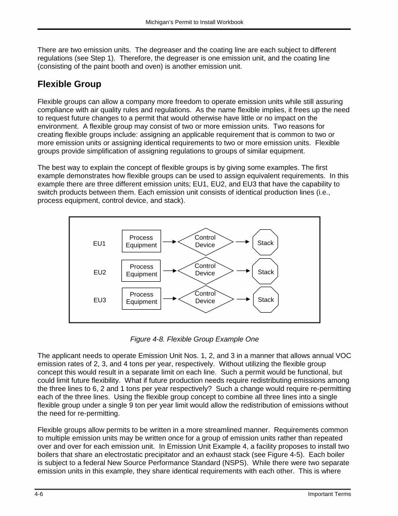
There are two emission units. The degreaser and the coating line are each subject to different regulations (see Step 1). Therefore, the degreaser is one emission unit, and the coating line (consisting of the paint booth and oven) is another emission unit. Flexible Group Flexible groups can allow a company more freedom to operate emission units while still assuring compliance with air quality rules and regulations. As the name flexible implies, it frees up the need to request future changes to a permit that would otherwise have little or no impact on the environment. A flexible group may consist of two or more emission units. Two reasons for creating flexible groups include: assigning an applicable requirement that is common to two or more emission units or assigning identical requirements to two or more emission units. Flexible groups provide simplification of assigning regulations to groups of similar equipment. The best way to explain the concept of flexible groups is by giving some examples. The first example demonstrates how flexible groups can be used to assign equivalent requirements. In this example there are three different emission units; EU1, EU2, and EU3 that have the capability to switch products between them. Each emission unit consists of identical production lines (i.e., process equipment, control device, and stack).
Figure 4-8. Flexible Group Example One The applicant needs to operate Emission Unit Nos. 1, 2, and 3 in a manner that allows annual VOC emission rates of 2, 3, and 4 tons per year, respectively. Without utilizing the flexible group concept this would result in a separate limit on each line. Such a permit would be functional, but could limit future flexibility. What if future production needs require redistributing emissions among the three lines to 6, 2 and 1 tons per year respectively? Such a change would require re-permitting each of the three lines. Using the flexible group concept to combine all three lines into a single flexible group under a single 9 ton per year limit would allow the redistribution of emissions without the need for re-permitting. Flexible groups allow permits to be written in a more streamlined manner. Requirements common to multiple emission units may be written once for a group of emission units rather than repeated over and over for each emission unit. In Emission Unit Example 4, a facility proposes to install two boilers that share an electrostatic precipitator and an exhaust stack (see Figure 4-5). Each boiler is subject to a federal New Source Performance Standard (NSPS). While there were two separate emission units in this example, they share identical requirements with each other. This is where
Control Device Stack
EU3
Process Equipment
EU2
EU1
Process Equipment
Process Equipment
Control Device
Control Device
Stack
Stack

Michigan’s Permit to Install Workbook
Important Terms 4-7
creation of a flexible group becomes useful. In the permit, the two emission units can be grouped together as a flexible group to which the NSPS requirements apply. While flexible groups work well for combining identical requirements or grouping annual emission limits, they only offer limited value for combining short term or line-specific emission limits. Individual emission units occasionally have their own short term emission limits that enforce specific technology-based requirements (i.e., BACT, RACT, LAER, T-BACT). Such short term limits can only be combined in the limited circumstances where the combined limit can be demonstrated to meet the underlying regulatory requirement. When such a demonstration cannot be made, there is little benefit to creating a flexible group. As an example, consider the facility described in Figure 4-8. Assume that in addition to the ton per year limits, EU1, and EU2 are required by a federal regulation to install and operate baghouse controls, but EU3 is not. Instead, the company chooses to install a cyclone collector for EU3. Grouping these limits becomes a problem because EU3 cannot comply with a requirement to install and operate a baghouse. In the same example, assume that the State Toxics program required short term emission limits on EU1, EU2 and EU3 of 1.5, 2.5 and 3.0 pounds per hour, respectively. These limits cannot be combined into a single 7.0 pounds per hour limit because such a limit would allow any one of the three lines to emit up to 7.0 pounds per hour, violating the limits that apply to each line. Instead, the lowest of the limits (1.5 pounds per hour) would apply – over-restricting the capacity of the other two emission units. It may still be possible to utilize a flexible group for these three emission units under these circumstances, but the combined annual emission limit that would apply to the group would have to be coupled in the permit with hourly emission limits that apply separately to each emission unit. Why Are Emissions Units Important to Air Permitting? The grouping of devices provides order and consistency in the application of the various regulatory requirements. Many facilities have hundreds or even thousands of process devices, control devices, and stack devices. Many of these devices are subject to multiple air regulatory programs such as the Permit to Install, Renewable Operating Permit (ROP) program and Michigan Air Emission Reporting System (MAERS). To provide some order and consistency across the various air regulatory programs, it makes sense to place the devices into some type of logical grouping, or emission unit. The grouping of devices in your Permit to Install should be the same grouping found in your ROP and MAERS. You need to report your emissions in MAERS at the emission unit level, as opposed to reporting the emissions from each individual process device or reporting your emissions under one lump sum for the entire facility. The ROP program requires a facility to identify all applicable state and federal regulations by emission unit. In summary, the emission unit has become the building block of the air programs. Stationary Source A stationary source consists of all the buildings and structures that house the emission units. If your stationary source has existing permits and has submitted the annual Michigan Air Emissions Reporting System (MAERS) report, then it should have a unique State Registration Number (SRN). All of the emission units belonging to this SRN define your stationary source. If your facility does not report to MAERS, then the first time you submit an application for a Permit to Install, an SRN will be issued for your facility.

Michigan’s Permit to Install Workbook
4-8 Important Terms
Stationary sources can range from a simple auto body shop, which can contain two emission units (i.e., a spray paint booth and solvent cleaning station), to a pharmaceutical manufacturing plant, which can contain multiple buildings housing hundreds of emission units and flexible groups. Permits to Install can be issued for devices. Devices may be process devices, control devices or stacks. Devices may be grouped together into emission units based on regulatory applicability or their dependency on one another. Emission units may be grouped together into flexible groups based on common regulatory requirements or grouping of limits. Finally, all emission units and/or flexible groups at one site make up a stationary source. Figure 4-9 illustrates this hierarchy.
Device = Process, Control or Stack
Stationary Source
Flexible Group
Emission Unit
Device Device
Emission Unit
Device Device
Emission Unit
Device Device
Figure 4-9. Equipment Grouping Hierarchy

Michigan’s Permit to Install Workbook
Important Terms 4-9
National Ambient Air Quality Standards The Clean Air Act requires the U.S. EPA to establish maximum allowable pollutant concentrations in the ambient air that may cause harm to the public health or welfare. In response, the U.S. EPA has developed the National Ambient Air Quality Standards (NAAQS). The NAAQS fall into two categories: primary and secondary standards. Primary standards are protective of public health while secondary standards are protective of the public welfare (i.e., soils, vegetation and structures). National standards have been established for particulate matter (PM10 and PM2.5), carbon monoxide (CO), sulfur dioxide (SO2), nitrogen dioxides (NO2), lead (Pb), and ozone. Ozone is formed in the ambient air by the reaction of volatile organic compounds (VOCs) and NOX under certain atmospheric conditions (i.e., primarily hot and sunny). Ozone is therefore, regulated through its precursors (NOX and VOCs). The Michigan Air Sampling Network, which is operated by the Air Quality Division, consists of 130 sites and over 230 monitoring sensors. This network monitors the levels of the six criteria pollutants. Each monitor measures the airborne concentration of one or more pollutants for comparison with the NAAQS. Monitored pollutant concentrations from each monitoring site represent pollutant concentrations for the surrounding region of the State. Regions of the State in which the measured air quality is cleaner (i.e., having lower pollutant concentrations) than the NAAQS, are referred to as attaining the NAAQS, or being in attainment. In these attainment areas, federal regulations attempt to prevent the degradation of air quality by minimizing the impact of new emissions in the area. Most counties in Michigan are currently designated as attainment areas for all pollutants with NAAQS. Regions of the State in which the measured air quality is dirtier (i.e., having higher pollutant concentrations) than the NAAQS are referred to as not attaining the NAAQS, or being in nonattainment. In nonattainment areas, regulations attempt to improve the air quality in order to return the area to attainment. You can view the current attainment status for all Michigan counties at www.michigan.gov/air (select “SIP & Attainment”).

Michigan’s Permit to Install Workbook
4-10 Important Terms
Air Contaminants
In high school chemistry you learned that all matter is in either a solid, liquid, or gaseous state. The same applies to air contaminants. There are solid and liquid air contaminants that we call particulates, and there are many air pollutants in a gaseous state. All state and federal air quality regulations, such as the New Source Performance Standards (NSPS) or the Renewable Operating Permit (ROP) program target a defined group or family of air contaminants. Table 4-1 summarizes all of the families of air contaminants. Many air contaminants belong to more than one family. Most of the hazardous air pollutants (HAPs) are also considered volatile organic compounds (VOCs). For example, xylene is a VOC, it is a Toxic Air Contaminant (TAC) under Michigan’s Rules 224-230 and it is also one of the approximately 188 HAPs. Sulfuric Acid on the other hand is not a VOC and not a HAP, but is a TAC. For further information about air contaminants, contact the Office of Environmental Assistance’s (OEA) at 800-662-9278 or visit their website at www.michigan.gov/air (select “Compliance” then “Clean Air Assistance”).
Table 4-1: Families of Air Contaminants
Criteria The criteria air pollutants are (PM10 and PM2.5), sulfur dioxide (SO2), nitrogen Oxides (NOx), ozone, carbon monoxide (CO), and lead (Pb).
Class I and II Chlorofluorocarbons (CFCs) and Hydrochlorofluorocarbons (HCFCs)
Ozone Precursors VOCs and NOx. Most sources do not emit ozone directly. However, they may emit VOCs and NOx,, which in the presence of sunlight contribute to ozone formation.
Hazardous Air Pollutants (HAPs)
Approximately 188 compounds identified by the EPA. The Agency is regulating sources that are the primary emitters of these compounds through the promulgation of the National Emission Standards for Hazardous Air Pollutants (NESHAPs). See Appendix A for a listing of HAPs.
Toxic Air Contaminants
According to Rule 120(f) of the Michigan Air Pollution Control Rules, any substance that is or may become harmful to public health or the environment can be regulated as a toxic air contaminant, except for 41 substances that have been excluded. See Appendix B for a listing of the excluded compounds.
New Source Performance Standards (NSPS)
The NSPS regulate the emission of the following air pollutants from various sources: criteria air pollutants plus dioxin/furan, fluorides, hydrogen chloride, hydrogen sulfide, sulfuric acid, total reduced sulfur, reduced sulfur compounds, and more.
National Emission Standards for Hazardous Air Pollutants (NESHAPs)
The following air pollutants are regulated by the NESHAPs that were promulgated prior to the Clean Air Act Amendments of 1990: arsenic, asbestos, beryllium, benzene, mercury, radionuclides, and vinyl chloride.
Section 112(r) Air Pollutants
Section 112(r) of the 1990 Clean Air Act Amendments requires risk management planning and accidental release prevention. A total of 77 toxic chemicals and 63 flammable chemicals are regulated under Section 112(r).
Regulated Air Pollutants
All air pollutants regulated under the federal Clean Air Act: criteria air pollutants, ozone precursors, HAPs, NSPS, NESHAP, and Class I and II air pollutants.

Michigan’s Permit to Install Workbook
Important Terms 4-11
Emission Rates There are three types of annual emission rates of air contaminants that are used in air permitting:
• Potential to Emit • Projected Emissions • Maximum Allowable Emissions
Each of these emission rates are expressed in units of tons of air contaminant emitted per year. The following is a discussion of each type of emission rate and the role each one plays in permitting. Potential to Emit Potential to Emit (PTE), as defined in Michigan Rule 116(m), is the maximum capacity of a source to emit each air contaminant while operating under its physical and operational design. Any physical or operational limit on the capacity of the source to emit an air contaminant is considered part of its design only if the limit is legally enforceable. The PTE of emission units can be reduced by placing restrictions on operating hours, the use of control devices, and/or the amount of raw materials used, as long as the restrictions are part of a special condition of a Permit to Install or Renewable Operating Permit. Another name for restricted PTE is maximum allowable emission rate (see discussion below on how to calculate the maximum allowable emission rate). It is impossible for a source to emit air contaminants in excess of its potential to emit (without physical modification). It is possible for a source to emit more than its maximum allowable emission rate. In this case, it requires operating outside the limitations found in the special conditions of its Permit to Install. The reason why PTE is such an important concept is because the applicability of state and federal requirements is often dependent upon potential to emit, not actual emissions. PTE remains consistent and predictable because it is based upon maximum capacity, continuous operation, or is reflected in an emission limitation of a Permit to Install. Actual emissions can deviate day-to-day and year-to-year and are unpredictable. We need to calculate the PTE for each air contaminant emitted from each emission unit and also the PTE for each air contaminant for the source. A source’s PTE is simply the summation of the PTE of each air contaminant from all emission units. For example, Company ABC operates three emission units: Boiler, Coating Line #1, and Coating Line #2. The company received a Permit to Install for the two coating lines. The permit limits the emissions of VOCs to 28 and 15 tons per year, respectively. The boiler doesn’t have a permit because it is exempt from Permit to Install requirements by Rule 282. The company calculated the boiler’s PTE assuming continuous operation and maximum capacity. Table 4-2 identifies the PTE of each air contaminant from each emission unit and from the source. For more information about calculating PTE, including U.S. Environmental Protection Agency guidance and several PTE calculation worksheets, visit the Air Quality Division’s Potential to Emit website: www.michigan.gov/air (select “Permits” then “Potential to Emit”).

Michigan’s Permit to Install Workbook
4-12 Important Terms
Table 4-2: Potential to Emit Summary Emission Unit VOC CO NOx SO2 PM Coating Line 1 28 --- --- --- ---
Coating Line 2 15 --- --- --- ---
Boiler 6 5 1 3 1
PTE of Source 49 5 1 3 1 Projected Emission Rate Projected emission rate is the annual emission rate of air contaminants from an emission unit operating at the expected normal capacity and normal operating hours. Control device efficiency is considered in the calculation. Often the projected emission rate will be much lower than the potential to emit because very few emission units will continuously operate at their maximum rated capacity. The applicability of some regulations is determined based on the projected emission rate for an emission unit. Maximum Allowable Emission Rate The maximum allowable emission rate is the annual emission rate of air contaminants from an emission unit that the source will accept as a permit restriction. Permit conditions often limit operating hours, material usage, or number of products manufactured. Permit conditions also typically include an annual emission rate limitation. If the source exceeds the maximum allowable emission rate, it is operating in violation of its Permit to Install. Maximum allowable emission rates can be calculated by first determining the projected emission rate and then incorporating a buffer (safety factor) to ensure compliance. The safety factor should be designed to allow the source to continue operating in compliance with its Permit to Install even with an unexpected increase in product demand. In the following example, a company proposes to install a commercial oil-fired boiler. At maximum capacity the boiler will burn 100 gallons of oil per hour. The company typically burns 90,000 gallons of distillate (No. 2) oil per year and expects this level of operation to remain unchanged. The emission factor for CO is 5.0 pounds of CO emitted per 1,000 gallons of distillate oil burned. Determine the PTE and the projected and maximum allowable emission rates of CO. Potential to Emit 5 lb of CO/1,000 gal of oil x 100 gal/hr x 24 hr/day x 365 day/yr = 4,380 lbs CO/yr Projected Emission Rate 5 lb of CO/1,000 gal of oil x 90,000 gal/yr = 450 lbs CO/yr Knowing that the facility projects emissions of 450 lb CO/yr it can wisely request a permit limit that allows for growth and/or unexpected production increases. Maximum Allowable Emission Rate 5 lb of CO/1,000 gal of oil x 90,000 gal/yr x 1.20 (safety factor) = 540 lbs CO/yr

Michigan’s Permit to Install Workbook
Important Terms 4-13
Source Classification Once you have calculated your facility’s potential to emit (PTE) you can determine whether you are a “major” or “minor” source of air pollution. This distinction is important because major sources are subject to more regulations than minor sources. Major Source The installation of a new source or emission unit whose potential to emit (or maximum allowable emission rate if the potential to emit is restricted by conditions of a Permit to Install) air contaminants exceeds specific thresholds, is considered a major source. An existing major source that installs new emission units or modifies existing units and results in emissions increases greater than defined thresholds is considered a major modification. Major sources and major modifications trigger some very stringent air regulations which are beyond the scope of this guidebook. If you are submitting a permit application for emissions units having potential to emit greater than the major source or major modification thresholds, you may wish to consider hiring a consultant to complete your application. Contact the Office of Environmental Assistance at 800-662-9278 or find it online by going to www.michigan.gov/air (“Compliance” then “Compliance Assistance Resources” then Environmental Consultant Assistance”). The following discussion highlights the criteria used to determine if a proposed new source or emission unit, or modification of an existing source or emission unit, is subject to the major source or major modification regulations. It is important to understand the level at which major source regulations become applicable so you have the opportunity to avoid them, if possible, by taking steps to restrict your emissions. A major source is a stationary source whose potential to emit exceeds established annual emission rate thresholds. These thresholds have been set for individual air contaminants. There are four different types of major sources. The federal New Source Review program establishes thresholds for major source review in attainment areas (Prevention of Significant Deterioration [PSD]) and in nonattainment areas. Section 112(g) of the federal Clean Air Act and the various National Emission Standards for Hazardous Air Pollutants (NESHAP) establish thresholds for major sources of HAP emissions. Michigan’s Renewable Operating Permit (ROP) program establishes its own set of major source thresholds. Each one of these major source types has its own applicability threshold. For example, if a source’s potential to emit sulfur dioxide is greater than 100 tons per year, or its potential to emit a hazardous air pollutant (HAP) is greater than 10 tons, it would qualify as a major source under the ROP program. However, to be subject to the PSD regulations, some sources would have to emit more than 250 tons of a criteria air contaminant. Table 4-3 provides a simplified overview of the major source thresholds for each type of major source.
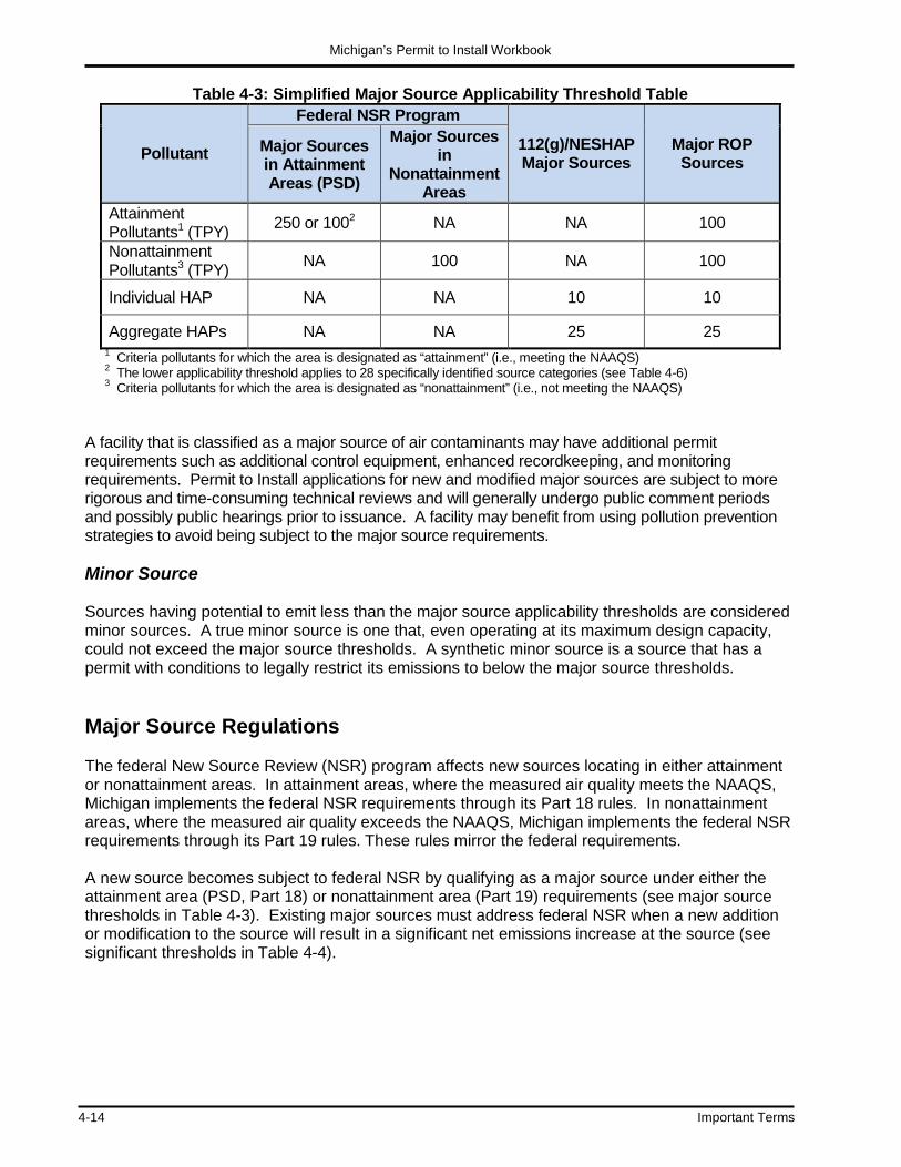
Michigan’s Permit to Install Workbook
4-14 Important Terms
Table 4-3: Simplified Major Source Applicability Threshold Table
Pollutant
Federal NSR Program
112(g)/NESHAP Major Sources
Major ROP Sources
Major Sources in Attainment Areas (PSD)
Major Sources in
Nonattainment Areas
Attainment Pollutants1 (TPY) 250 or 1002 NA NA 100
Nonattainment Pollutants3 (TPY) NA 100 NA 100
Individual HAP NA NA 10 10
Aggregate HAPs NA NA 25 25 1 Criteria pollutants for which the area is designated as “attainment” (i.e., meeting the NAAQS) 2 The lower applicability threshold applies to 28 specifically identified source categories (see Table 4-6) 3 Criteria pollutants for which the area is designated as “nonattainment” (i.e., not meeting the NAAQS)
A facility that is classified as a major source of air contaminants may have additional permit requirements such as additional control equipment, enhanced recordkeeping, and monitoring requirements. Permit to Install applications for new and modified major sources are subject to more rigorous and time-consuming technical reviews and will generally undergo public comment periods and possibly public hearings prior to issuance. A facility may benefit from using pollution prevention strategies to avoid being subject to the major source requirements. Minor Source Sources having potential to emit less than the major source applicability thresholds are considered minor sources. A true minor source is one that, even operating at its maximum design capacity, could not exceed the major source thresholds. A synthetic minor source is a source that has a permit with conditions to legally restrict its emissions to below the major source thresholds. Major Source Regulations The federal New Source Review (NSR) program affects new sources locating in either attainment or nonattainment areas. In attainment areas, where the measured air quality meets the NAAQS, Michigan implements the federal NSR requirements through its Part 18 rules. In nonattainment areas, where the measured air quality exceeds the NAAQS, Michigan implements the federal NSR requirements through its Part 19 rules. These rules mirror the federal requirements. A new source becomes subject to federal NSR by qualifying as a major source under either the attainment area (PSD, Part 18) or nonattainment area (Part 19) requirements (see major source thresholds in Table 4-3). Existing major sources must address federal NSR when a new addition or modification to the source will result in a significant net emissions increase at the source (see significant thresholds in Table 4-4).

Michigan’s Permit to Install Workbook
Important Terms 4-15
Major Source Review for Attainment Areas and for Nonattainment Areas PSD applies in areas of the state in which the air quality currently meets the NAAQS (i.e., attainment areas). The program is designed to prevent significant deterioration of the air quality in such areas, while allowing economic growth. The PSD program requires a source to undergo a control technology evaluation to ensure that the Best Available Control Technology (BACT) is applied and to conduct rigorous air quality modeling to ensure the NAAQS (and other ambient air quality criteria) will not be exceeded. A different form of major source review affects sources located in areas of the state that are not attaining a NAAQS. The Part 19 requirements are designed to improve the air quality in the nonattainment area (i.e., to return the area to attainment status) while still allowing economic growth. Part 19 requires a source to meet the Lowest Achievable Emission Rate (LAER) for the nonattainment pollutant(s). LAER is the most stringent level of emissions reduction achieved for the same, or similar, source type. In addition, any nonattainment pollutant emissions increases from a source subject to Part 19 must be compensated for by obtaining emission reductions (i.e., offsets) at a greater than one to one ratio within the nonattainment area. In other words, there must be a net emissions reduction of the nonattainment pollutant. .
Table 4-4: Federal NSR Significant Thresholds Pollutant/Source Type Threshold (TPY)
CO 100 NOx 40 SO2 40 Ozone (determined as VOC) 40 Lead 0.6 PM 25 PM-10 15 PM-2.5/(SO2 as precursor) 10/(40) Hydrogen Sulfide 10 Total Reduced Sulfur 10 Reduced Sulfur Compounds 10 Sulfuric Acid Mist 7 Fluorides 3 Municipal Solid Waste Landfill Emissions (measured as non-methane organic compounds) 50
Municipal Waste Combustor Acid Gases 40 Municipal Waste Combustor Metals 15 Municipal Waste Combustor Organics 3.5 x 10⁻⁶

Michigan’s Permit to Install Workbook
4-16 Important Terms
The proposed installation of a new source consists of the installation of one or more emission units at a new site (e.g., a new auto assembly plant or a new electric generating station). The new source will be subject to federal NSR as described below:
Attainment Areas (PSD) Nonattainment Areas
• Potential (or maximum allowable) emissions of at least one attainment pollutant in excess of the major source thresholds listed in Table 4-3
• Potential (or maximum allowable) emissions of at least one nonattainment pollutant in excess of the major source thresholds listed in Table 4-3
• PSD (Part 18 requirements) will then apply to that pollutant and each additional attainment pollutant having potential (or maximum allowable) emissions in excess of its Significant Threshold as listed in Table 4-4
• Part 19 requirements will then apply to that pollutant
• Part 19 requirements will apply to
each additional nonattainment pollutant having the potential (or maximum allowable) emissions in excess of its Significant Threshold as listed in Table 4-4, but less than 100 tons per year
Michigan Rule 116(m) defines the term “potential to emit,” and contains an explanation of when fugitive emissions must be included in the calculations of potential to emit. If your facility is one of those required to include fugitive emissions in its potential to emit (see Tables 4-5 and 4-6), then fugitive emissions will contribute to the determination of federal NSR applicability. Other source types do not need to include fugitive emissions in determining their potential to emit for federal NSR applicability. Modifications to Existing Major Sources: A proposed modification of an existing source may consist of a physical change, a change in the method of operation of existing emission units, and/or the installation of one or more new emission units at an existing source. The modification will be subject to major source review requirements as described below: • Part 18 will apply when the existing source is a “major source” for PSD and the modification will
result in both an emissions increase itself and a net emissions increase at the entire facility that both exceed the attainment pollutant’s Significant Threshold listed in Table 4-4.
• Part 19 will apply when the existing source is a “major source” for nonattainment areas and the
modification will result in both an emissions increase itself and a net emissions increase that both exceed the nonattainment pollutant’s Significant Threshold listed in Table 4-4.
The process of determining whether a change at a major source will cause a net emissions increase in excess of any Significant Threshold is referred to as emissions netting. Calculating a net emission change is very complex and involves consideration of certain previous and planned emission changes at the existing major source that are unrelated to the current modification. An internal Michigan Department of Environmental Quality (MDEQ) memo (dated October 2004),

Michigan’s Permit to Install Workbook
Important Terms 4-17
provides guidance for review of applications for netting out of major source review. Contact the Office of Environmental Assistance at 800-662-9278 for a copy of the guidance document.
Table 4-5: 28 Source Categories Carbon black plants (furnace process) Charcoal production plants Chemical process plants Coal cleaning plants (with thermal dryers) Coke oven batteries Fossil fuel boilers (or combination thereof)
totaling more than 250 million Btu/hr. heat input
Fossil fuel-fired steam electric plants of more than 250 million Btu/hr. heat input
Fuel conversion plants Glass fiber processing plants Hydrofluoric acid plants Iron and steel mill plants Kraft pulp mills Lime plants Municipal incinerators capable of charging
more than 250 tons of refuse per day
Nitric acid plants Petroleum refineries Petroleum storage and transfer units with a
total storage capacity exceeding 300,000 barrels
Phosphate rock processing plants Portland cement plants Primary aluminum ore reduction plants Primary copper smelters Primary lead smelters Primary zinc smelters Secondary metal production plants Sintering plants Sulfuric acid plants Sulfur recovery plants Taconite ore processing plants
Table 4-6: Source Categories Regulated Under Sections 111 and 112 of the Clean Air Act
Asphalt concrete plants
Secondary lead smelters and refineries
Sewage treatment plants
Phosphate fertilizer plants
Ferroalloy production plants
Grain elevators
Stationary gas turbines
Stationary sources which are subject to the federal national emission standards for hazardous air pollutants for the following materials: Asbestos, Beryllium, Mercury, Vinyl Chloride

Michigan’s Permit to Install Workbook
4-18 Important Terms
Examples: Example 1 - New Source A wood products company proposes to construct a new plant in a county that is in a moderate ozone nonattainment area. The plant consists of a natural gas and wood waste fired dryer to condition wood chips, and a lamination process where a solvent based adhesive and pressure is used to form the chips into a board. Air contaminants will be emitted from two stacks: one stack serves the dryer and the other serves the lamination process. The company estimates that the emissions from each stack, in tons per year, would be the following:
Pollutant Dryer Lamination Process Total
VOC 60 200 260
NOX 35 0 35 CO 105 0 105
Discussion: (a) Part 19 Applicability The proposed source is located in a moderate ozone nonattainment area. Therefore, VOC and NOX are the nonattainment pollutants. VOC emissions qualify the source as major under Part 19 because they exceed the 100 ton per year major source threshold. NOX emissions do not exceed their 40 ton per year significant threshold, so NOX emissions are not subject to Part 19. (b) Part 18 (PSD) Applicability As described above, the proposed source is subject to Part 19 because it will exceed 100 TPY of a nonattainment pollutant, but it is not a major PSD source (i.e., it will not exceed 250 TPY of an attainment pollutant.) Therefore, the emissions of CO are not subject to PSD because they do not exceed the PSD major source threshold – even though they exceed the CO significant threshold of 100 tons per year.

Michigan’s Permit to Install Workbook
Important Terms 4-19
Example 2 - Modification of Existing Source A marine products company proposes to expand its existing fiberglass boat building plant to double its size in a county that is a moderate ozone nonattainment area. The existing facility consists of a fiberglass layup area where the boat hulls and decks are fabricated utilizing both chopped and sheets of glass fibers and various styrene-polyester resins. The emissions allowed from the existing facility under its operating permit and the projected plant emissions after the modification are as follows:
Pollutant
Existing Facility Emissions (TPY)
Post-Change Facility Emissions (TPY) Change
(TPY) Lay Up Area Assembly Total Lay Up
Area Assembly Total
Particulate Matter 10 3 13 18 5 23 +10
Sulfur Dioxide <0.1 <0.1 <0.2 0.1 0.1 0.2 0
Nitrogen Oxides 8 5 13 14 9 23 +10
Carbon Dioxide 2 1 3 4 2 6 +3
Volatile Organic Compounds
88 15 103 151 25 176 +73
Discussion (a) Part 18 (PSD) Applicability The source is not a major source as defined under Part 18. No air contaminants are subject to PSD review.
(b) Part 19 Applicability The existing source is a major source under the Part 19 rules. Since the source is located in an area designated as nonattainment for ozone and the increase in VOC emissions exceeds the Significant Threshold, major source review under Part 19 is required for the VOC increase.
(c) Question If, in the above example, the existing source’s emissions of VOC were 90 tons instead of 103 tons, would Major Offset program review still apply?
(d) Answer No, it would not. The source would be an existing minor source. To become subject to the major offset program, the modification would have to be a major source all by itself (i.e., greater than 100 tons of VOC per year). The Significant Threshold determines applicability only for modifications at existing major sources.

Michigan’s Permit to Install Workbook
4-20 Important Terms
Section 112(g) of the Federal Clean Air Act Section 112(g) of the federal Clean Air Act regulates emissions of hazardous air pollutants (HAPs). Rule 299(e) of the Michigan Air Pollution Control Rules adopts Section 112(g). According to Section 112(g), if you are proposing to install or reconstruct a production unit (this is similar, but not identical, to an emission unit) that is a major source of HAPs, you are required to equip that production unit with the Maximum Achievable Control Technology (MACT). As described in Table 4-3, a major source of HAPs has the potential to emit a single HAP greater than or equal to 10 tons per year, or the potential to emit greater than 25 tons per year of a combination of HAPs. Further guidance on demonstrating compliance with Section 112(g) in your Permit to Install application submittal is found in the Air Quality Division’s Operational Memorandum No. 15 entitled “Procedure For Processing Permit Applications Subject to Federal Clean Air Act Section 112(g)”. This document can be obtained at www.michigan.gov/air (select “News and Info” then “State Air Laws and Rules” then “AQD Policy and Procedures”). Renewable Operating Permit In addition to the Permit to Install program, there is another air permitting program in Michigan – the Renewable Operating Permit (ROP) program. Title V of the 1990 Clean Air Act Amendments requires each state to implement a ROP program. The ROP is intended to consolidate all state and federal air quality requirements into one document. Thus, all of a facility’s Permits to Install, along with all other applicable air pollution control requirements will be incorporated into one permit, and the old documents (permits) will be void. A ROP is valid for five years and then it must be renewed. Not all facilities are subject to the ROP program. Only major sources of air emissions must apply. A major source is a facility that has the potential to emit air contaminants above the emission thresholds described in Table 4-3. Opting Out of the ROP Program: Since the major source determination for the ROP program is based on potential to emit instead of actual emissions, many facilities operating only a few emission units could fit into the major source category. These facilities can avoid the ROP program by obtaining legally enforceable limits that reduce their facility’s potential to emit. The AQD’s Operational Memorandum No. 4 explains two mechanisms for limiting the applicability of the ROP program:
1. A facility with actual emissions less than 50 percent of the major source thresholds can use Rule 208(a) to register with the AQD and annually certify that actual emissions remain below 50 percent of the ROP major source thresholds.
2. A facility can obtain a synthetic minor permit to establish emission limits below the ROP
major source thresholds. A synthetic minor permit may either be a general Permit to Install for a source category or a case-by-case Permit to Install.

Michigan’s Permit to Install Workbook
Important Terms 4-21
Incorporating Permit Conditions into ROP: After a facility has submitted a ROP application or received a ROP, it must still obtain a Permit to Install before installing, constructing, modifying, or relocating equipment. For facilities subject to the ROP program, the AQD will eventually incorporate Permit to Install conditions into the ROP. ROP Program’s Effect on Permit to Install Conditions: Because of the ROP program, the AQD has changed a couple of aspects of the Permit to Install program:
1. The AQD now incorporates underlying applicable requirements into permit conditions. In the past, Permits to Install did not always identify the applicable requirement for a special condition. However, Michigan Rule 213 requires that the regulatory basis for each permit condition be clearly identified in the ROP. Therefore, Permit to Install conditions now contain the underlying applicable requirement.
2. The AQD now includes monitoring and/or record keeping requirements in permit conditions
that are sufficient for the facility to demonstrate compliance with each special condition. Go the AQD’s website www.michigan.gov/air (select “Permits”) for more information about the ROP program.

Michigan’s Permit to Install Workbook
4-22 Important Terms
NOTES

CHAPTER 5
Additional Supporting Information
In This Chapter:
• Introduction • Cover Letter • Site Map • Plant Layout Map • Emission Unit Description • Process Flow Diagrams • Stack Descriptions/Parameters • Emission Calculations
O Emission Factors and Software O Mass Balance O Manufacturer’s Performance Tests O Emission Limit Contained in a Regulation O Good Engineering Judgment
• Regulatory Discussion • Air Toxics Regulations
O State Regulations O Federal Regulations
• Odor Issues • Air Quality Plans • Assembling Your Permit Application Submittal


Michigan’s Permit to Install Workbook
Additional Supporting Information 5-1
CHAPTER 5: Additional Supporting Information Introduction Chapter 5 reviews what additional supporting information must accompany the one-page application form described in Chapter 3. This information includes site maps, description of the emission units, calculations of projected and maximum allowable emissions, applicable state and federal rules, preparation of an air toxics review, and other documentation that completes the Permit to Install application submittal. Chromewell Plating, Inc.’s proposed new installation of several emission units is used to illustrate how to prepare the necessary supporting information. In addition to the guidance found in this chapter, the Air Quality Division (AQD) has developed additional supporting information sheets for various sources control devices. They are listed in Table 5-1. These sheets provide some specific guidelines on what should be included in the supporting documentation portion of the Permit to Install application submittal. For example, specific state and federal rules applicable to the emission unit or source are identified in the information sheets. Go to www.deq.state.mi.us/aps (click on “Application Form, Instructions and Guidance Documents”) to access them. The additional supporting information sheets will streamline your permit application submittal.

Michigan’s Permit to Install Workbook
5-2 Additional Supporting Information
Table 5-1: Additional Supporting Information Sheets
Processes/Process Equipment
• Anhydrous Ammonia Storage • Asphalt Plants • Auto Paint Shops and Assembly Plants • Boilers • Chemical/Pharmaceutical Processes • Coating Operations – Metal Coils • Coating Operations – Metal Furniture • Coating Operations – Misc. Metal Parts • Coating Operations – Plastic Parts • Coating Operations – Wood Furniture • Concrete Batch Plants • Crushers (Concrete, Asphalt, Rock) &
Limestone Quarries • Degreasers • Dry Cleaners • Engine Test Cells • Ethylene Oxide Sterilizer • Fiberglass Reinforced Plastics Operations • Fluorescent Light Bulb Crushers • Foundry Processes • Gas Turbines
• Grain Elevators • Graphic Arts - Printing • Incinerators - General Refuse
• Incinerators - Medical Waste
• Landfill Waste-to-Energy Facilities
• Material Handling Operations • Metal Shredders • Municipal Waste-to-Energy Facilities • Natural Gas Sweetening Facilities • Paper Machines • Reciprocating Internal Combustion
Engine • Remediation Operations - Groundwater • Remediation Operations – Soil • Rendering Facilities • Shot Blasting Equipment • Sour Oil and Gas Well Equipment • Storage Tanks – General • Surface Treatment (Plating, etc.) • Waste Oil Firing Equipment • Welding Operations • Woodworking Operations
Air Pollution Control Equipment
• Acid Gas Scrubber
• Afterburner – Catalytic Oxidizer • Afterburner – Thermal Oxidizer • Cyclone Dust Collector
• Condenser
• Electrostatic Precipitator
• Fabric Filers (baghouse, cartridge) • Scrubbers

Michigan’s Permit to Install Workbook
Additional Supporting Information 5-3
Cover Letter It is recommended that you include a cover letter with the Permit to Install application submittal. In this letter, provide the following:
Additional background information and history about the source and its emission units. A clear explanation of why the application is being submitted. A letter of authorization (optional). A request for construction waiver (optional).
A brief history about the company is very useful to both the Permit Engineer and the AQD District Staff. The Permit Engineers are located in the Lansing office and may not be familiar with your facility. The Permit Engineer is the person assigned to evaluate your permit application. Any additional information about the history of the source and emission units helps the Permit Engineer determine if additional questions or other materials are necessary to make the application submittal technically complete (i.e., containing all of the information necessary to take action on the issuance of the permit). The majority of applications are submitted for new sources of air pollution that require a permit under Rule 201 of the Michigan Air Pollution Control Rules. However, a significant number of applications are submitted for reasons such as modifications, relocations, and for regulatory purposes like limiting a source’s potential to emit. The cover letter should clearly explain the action you are seeking from the Department. If you need to start construction or installation of a source or emission unit before the Permit to Install will be issued and can prove that it will cause undue hardship if you do not construct on schedule, you can request a construction waiver. The construction waiver request can also be incorporated into the cover letter. See Chapter 9 for more information about construction waivers. Cover letters must be signed by an authorized representative of the company who has authority for the operation of the proposed permit activity. This individual, at a minimum, must be equivalent to the representative that signed the Permit to Install application form. It is important to remember that the cover letter can set the tone as to how the application will be reviewed by the AQD. It can help the Permit Engineer quickly determine deficiencies in the application submittal and what type of permit conditions will be needed to ensure compliance. Although cover letters are not required, the use of one can reduce the time of the application review and can ensure that you meet the intent of application submittal.

Michigan’s Permit to Install Workbook
5-4 Additional Supporting Information
Example Cover Letter
CPI Chromewell Plating, Inc.
January 7, 2016 Permit Section Supervisor Air Quality Division Michigan Department of Environmental Quality P O Box 30260 Lansing, MI 48909-7760
To Whom It May Concern:
Please find the enclosed Permit to Install application submittal for Chromewell Plating, Incorporated. Our company is proposing to construct a new facility to be located near the City of Holland, Michigan. This application is for the facility which will include the following sources of air pollution: a decorative chrome plating line; an electrodeposition coating line; and two diesel-fired back-up generators. It is our intention to begin construction of the new facility on March 3, 2016. Therefore, we are requesting a construction waiver to proceed with the installation of the facility. We have reviewed the criteria for facilities that can be considered for construction waiver approvals and we feel confident that our facility meets the requirements established in the guideline. The emission units included in this application will not emit criteria air contaminants or hazardous air pollutants in excess of the major source thresholds. None of the proposed processes are considered as controversial sources, which would result in the need for a public comment period. The construction wavier will allow us to secure the footings and other foundation settings prior to obtaining the approved Permit to Install. We are under several contracts that require product delivery by August 27, 2016. If we are unable to honor our contracts we will suffer a significant economic penalty. If you need additional information or if you have any questions related to this application, please contact Mr. Tex Mills, our Plant Manager at (616) 555-1234. Again, thank you in advance for your consideration. Sincerely,
William Chromewell, III
William Chromewell, III Owner Chromewell Plating, Inc.
An Equal Opportunity Employer

Michigan’s Permit to Install Workbook
Additional Supporting Information 5-5
Site Map A site map is an aerial picture or plan view of the facility and the surrounding land use. Be sure to indicate the following on a site map:
The location of all property boundary lines. All fence line locations and barriers that prevent access to the property. The exhaust stack locations and the distances to the nearest property line. The location of all the standing structures on the property. The location of all standing structures, onsite and offsite, that are:
1) within 150 feet of any proposed stack/vent, or 2) taller than the stack and within a distance of five times the height of the building.
The proper scale on the map (note: proper scale is not required if all of the above information is clearly marked on the site map).
The North direction on the map. The Universal Transverse Mercator (UTM) grid coordinates if possible. The UTM coordinates
for your facility’s location can be obtained from www.topozone.com. It is important for the Permit Engineer to know if the site of the proposed source of air pollution is installed in an industrially developed area or if it is located in a rural or residential setting. This will aid the Permit Engineer and the AQD Modeling Staff in evaluating potential air quality impacts form the proposed activity. The terrain, building heights, position of the building on the site, and distances from the emission point to property line will all have an effect on how much the concentration of air contaminants leaving the stack will be diluted by the time they reach the property line of the facility.

Michigan’s Permit to Install Workbook
5-6 Additional Supporting Information
Plant Layout Map A plant layout map is an aerial or plan view of the facility with the roofs of the buildings removed. Plant layout maps can sometimes pull the entire application together at a glance. They give the Permit Engineer a snap shot of the relative positions of the emission units and show the flow of materials within the facility. A good plant layout map includes the following information:
Diagrams of emission units and relative locations within the building. Exhaust gas flow diagrams. Product flow diagrams. Exhaust stack locations and brief descriptions. General exhaust ventilation locations. Storage areas. A side profile of the plant indicating varying building heights.
EXAMPLE:

Michigan’s Permit to Install Workbook
Additional Supporting Information 5-7
Emission Unit Description A description of each emission unit must be included in the additional supporting information part of the application package. These descriptions are used by the permit reviewer to make important determinations about the emission unit(s), such as which rules and/or regulations are applicable and what methods should be used in calculating the emission of air contaminants. Unlike the brief description of the emission unit(s) in Field No. 6 of the air use application form, include in the additional supporting information a detailed description of each emission unit. Prepare your description as follows: Create a unique identifier or ID for each emission unit contained in the application. The ID should begin with the letters EU (which stands for emission unit) followed by a combination of letters, numbers, or keyboard characters. Any combination of letters, numbers, and keyboard characters can be used to create your IDs; however, blank spaces are not allowed. Your ID should not exceed 15 characters in length (including the two in the prefix). For example, Chromewell Plating, Inc. identified their chrome plating line as EUCHROMEPLATING. The Permit Engineer will assign an identifier to all of your emission units if you do not establish them yourself. The reason behind this coding is that many facilities applying for Permits to Install are also subject to the Renewable Operating Permit (ROP) program and the Michigan Air Emissions Reporting System (MAERS). Coding your emission units in the Permit to Install will facilitate the incorporation of these emission units in the ROP and MAERS. It is always best to name the emission unit yourself. Choose a name consistent with what your employees are familiar calling the equipment. One facility had three production lines. They were known on the plant floor as Line 2, Line 3 and Line 4, because the old line, Line 1, was removed several years ago. The application did not identify the emission units. The Permit Engineer identified the lines as Line 1, Line 2 and Line 3. What the employees called Line 2, the permit referred to as Line 1. What the permit referred to as Line 2, the employees called Line 3. When an inspector visited the facility and asked to see Line 2, a comedy of errors ensued. It appeared to the inspector that Line 2 was not meeting its permit requirements – until the confusion was sorted out. Provide the size, type, make, and model (if known) of each process device and control device that is part of the emission unit. If available, include any vendor literature as part of your emission unit description. If you have several vendors in mind for an emission unit, include them all and note that a final selection will be made at a later date. The selection of equipment from a specific vendor should not hold up your application if the general function of the equipment between all of the vendors is the same. Provide details of the type and feed rate of each material used in or produced by the process (including intermediate products if appropriate), in pounds per hour or similar measure. For fuel burning processes provide:
Exhaust gas air flow rates of the equipment. Schematic of how the processes and control devices are linked together. Equipment specifications such as operating temperature and maintenance intervals. Type and quantity of fuel used to fire equipment.

Michigan’s Permit to Install Workbook
5-8 Additional Supporting Information
EXAMPLE:
CPI Chromewell Plating, Inc. EMISSION UNIT DESCRIPTIONS Electrostatic Deposition Line: Metal parts are manually loaded on a rack and placed on a conveyor line that transports the parts through a series of processes to provide a reliable performance coating. First, oil and other rust inhibitors are removed from the parts in a 1% phosphate solution tank with a 4,000 gallon capacity that is operated at 100oF for roughly 5 minutes. The parts are then transported to a two-stage counter current rinsing station with a 4,000 gallon capacity that is operated at ambient temperature for approximately 5 minutes. The parts are then transported to a 4% ferric phosphate tank with a 4,000 gallon capacity that is operated at ambient temperature for roughly 5 minutes. The parts are then transported to a three-stage counter current rinsing station with a 6,000 gallon capacity that is operated at 100oF for approximately 7.5 minutes. Next, the parts are air dried at a blow dry station at approximately 120oF for roughly 2 minutes. The parts are then transported into a 16,000 gallon electrostatic deposition (E-Dip) tank containing a hazardous air pollutant (HAP) free, 12% solids solution. The E-Dip tank is operated at 120oF for approximately 22 minutes. The parts are then rinsed with a fine spray of deionized water for approximately 3 minutes. The spent deionized water is used to help replenish the E-Dip tank. The parts are transported to a curing oven with a rated heating capacity of 750,000 BTU/Hr, at 272oF for approximately 25 minutes, followed by a 30-minute cool down cycle. The entire E-Dip station is enclosed with several access doors. A properly designed containment area with a transfer sump pump surrounds the E-Dip station. A 75 MMBtu/hour natural gas-fired boiler heats the two phosphate cleaning tanks and the ferric phosphate tank.
Decorative Chrome Plating Line: Metal parts are manually loaded on a rack and placed on a conveyor line that transports the parts through a series of processes resulting in a fine chrome finish on automotive parts (i.e., chrome bumpers, chrome ball hitches, and fasteners). First, oil and other rust inhibitors are removed from the parts in a pretreatment process with a 6,000 gallon capacity that is operated at 100oF. The parts are then transported to a single-stage rinse station. The parts are then transported to an acid tank and a strike copper plating tank each with an 8,000 gallon capacity operated at 100oF. The parts are then transported to another single-stage rinse station. The parts are then treated in a copper electroplating tank, which has an 8,000 gallon capacity operated at 100oF. A three-stage counter current rinsing station precedes a semi-bright and bright nickel electroplating process, which is followed by another three-stage counter current rinsing station. Next, the parts are transported through a chrome electroplating tank, followed by a two-stage counter current rinsing station with a 6,000 gallon capacity that is operated at 100oF. The parts are then air dried at a blow dry station at approximately 120oF for roughly 2 minutes. Back-up Generators: Two 500-kilowatt diesel fuel-fired back-up generator units will be burning diesel fuel with a sulfur content of less than 0.5%. The generators will be used for back-up electrical power. The back-up generators will have a combined operating schedule of less than 500 total hours per year. Only one unit will be operated at any given time while the other is used as a secondary back-up system.
Rule 201 Exempt Ancillary Equipment: The ancillary equipment consists of the following items: a 100,000 Btu natural gas-fired air make-up unit for the office building; and two 30,000 acfm general ventilation fans for the shop. Several storage tanks are on hand for emergency evacuation of the E-Dip tank, the ferric phosphate tank, and the phosphate cleaning tank. All of this ancillary equipment is exempt from the Rule 201 requirements.

Michigan’s Permit to Install Workbook
Additional Supporting Information 5-9
Process Flow Diagrams Process flow diagrams are another tool that can be very helpful to a Permit Engineer. These are nothing more than a schematic of all the process, control, and stack devices that illustrates how all of the devices are linked together. They are used to complement both the plant layout maps and the emission unit descriptions (see examples on pages 5-10 and 5-11). These diagrams show both the product flow and the operational parameters of the system. Process flow diagrams can also list specific operating parameters like rates of application, temperature, pH level, tank capacity, airflow rates, and retention time. Stack Descriptions/Parameters Your Permit to Install application submittal must include a complete description of all exhaust stacks and vents from which air contaminants are emitted. General exhaust fans that are used for general ventilation purposes (i.e., they are not drawing air contaminants from a specific process device or emission unit out of the building) generally do not have to be included in the application. The parameters of interest to a Permit Engineer include:
Stack identifier such as Stack No. 1. The height of the stack/vent above ground level at the discharge point (in feet). The internal diameter or dimensions of the stack/vent at the discharge point (in inches). The orientation of the stack/vent discharge (i.e. vertical, horizontal, etc.). The volume flow rate of the exhaust gas in cubic feet per minute (cfm). Please note
whether the flow rate is based on actual or standard cfm (see discussion of stack gas flow rates below).
The approximate temperature of the exhaust gas at the discharge point (in degrees
Fahrenheit). A description of any rain protection devices. If the stack is equipped with stack testing ports, a description of the size and location of
such ports. Moisture content in the exhaust gas.
The AQD discourages the use of a rain cap or other device that obstructs the upward dispersion and dilution of exhaust gases. Figure 5-1 contains three designs of the proper rain protection devices. Upon completion of the review of the Permit to Install application, the Permit Engineer may recommend that the facility increase its proposed stack height to avoid emission downwash problems. It is often a good practice to design stacks with a height of at least 1.5 times the building height above the ground. For example, if the height of the building is 30 feet and you will be installing a stack on top of the roof, the length of the stack should be 15 feet, making the height of the stack 45 feet (30 x 1.5) from the ground.

Michigan’s Permit to Install Workbook
5-10 Additional Supporting Information
Proc
ess
Flow
Dia
gram
D
ecor
ativ
e C
hrom
e Pl
atin
g Li
ne
CPI C
hrom
ewel
l Pla
ting,
Inc.
Load
ing
Stat
ion
Pret
reat
men
t St
ep
Rin
se
Alka
line
Cle
anin
g R
inse
Ac
id D
ip
Strik
e Pl
atin
g of
C
oppe
r
Elec
tropl
atin
g of
Cop
per
Elec
tropl
atin
g of
Se
mib
right
(W
atts
) Nic
kel
Acid
Dip
Rin
se
Unl
oadi
ng
Stat
ion
Cou
nter
C
urre
nt
Rin
se
Cou
nter
C
urre
nt
Rin
se
Elec
tropl
atin
g of
Br
ight
(Wat
ts)
Nic
kel
Rin
se
Elec
tropl
atin
g of
C
hrom
ium
R
inse
Exam
ple:

Michigan’s Permit to Install Workbook
Additional Supporting Information 5-11
Proc
ess
Flow
Dia
gram
El
ectro
stat
ic D
ip L
ine
CPI C
hrom
ewel
l Pla
ting,
Inc.
Man
ual L
oadi
ng
Stat
ion
Phos
phat
e C
lean
ing
Stat
ion
100
o F
4,00
0 ga
l
Cou
nter
C
urre
nt
Rin
se
Ferri
c Ph
osph
ate
Tank
10
0 o F
4,
000
gal
Cou
nter
C
urre
nt
Rin
se
Blow
Dry
St
atio
n #1
12
0F
Elec
trost
atic
Dip
Ta
nk
120
o F
16,0
00 g
al
Dio
nize
d Sp
ray
Stat
ion
Blow
Dry
St
atio
n #2
12
0 o F
Infra
red
Cur
ing
Ove
n 35
0 o F
M
anua
l Loa
ding
&
Insp
ectio
n St
atio
n
Exam
ple:

Michigan’s Permit to Install Workbook
5-12 Additional Supporting Information
Stack Gas Flow Rates:
The volume of a gas varies with changes in pressure and temperature. In order to simplify comparison of gases, chemists adopted a set of standard conditions of temperature and pressure. Accordingly, Rule 119(m) of the Michigan Air Pollution Control Rules defines standard conditions as a gas temperature of 70o Fahrenheit (460 + 70o F = 530o R) and a gas pressure of 1 atmosphere (29.92 inches (760 mm) of mercury absolute). Converting ACFM to SCFM The volume of a gas or volume flow rate of a gas at one temperature and pressure can be converted to its volume or volume flow rate at standard conditions by using the ideal gas equation which relates pressure, volume, and temperature. According to the ideal gas law: Qstd = Qo(Tstd/To) (Po/Pstd) Where: Qstd = gas flow rate at standard temperature and pressure Qo = gas flow rate at actual conditions Pstd = pressure at standard conditions is 29.92 inches Hg or 1 atmosphere Tstd = temperature at standard conditions is 70o F Po = pressure at actual conditions (inches Hg) To = temperature at actual conditions (oF) Qscfm = Qacfm * (460 + 70o F ) * Po (460 + To) * Ps Converting SCFM to DSCFM
Certain processes will generate moisture in the stack gas Qdscfm = Qscfm * (1-% moisture) This approach can only be used for exhaust flows with less than 5 percent moisture Computer modeling is often used during review of Permit to Install applications to estimate the ground level concentration of air contaminants at the fence line. The stack/vent parameters listed above, along with distances to fenceline and quantity of pollutants emitted from the emission unit over time, are entered into the models that make these important predictions. The best way to communicate descriptions of exhaust stacks to a Permit Engineer is to present the stack parameters in tabular form (see page 5-14).
Michigan’s Permit to Install Workbook
Additional Supporting Information 5-13
Example:
Figure 4-1: Stack Designs
CPI Chromewell Plating, Inc.

Michigan’s Permit to Install Workbook
5-14 Additional Supporting Information
STACK IDENTIFICATION TABLE
Stack Identification
Stack ID Number
Building Height
Stack Height
Stack Diameter
Airflow (ACFM)
Exhaust Temp.
(oF)
Exhaust Direction
(U/D/H)*
Back-up Generators (BG -1)
1 25’ 32’ 20” 3,500 1,600 U
Decorative Chrome Plating -Cleaning Station
2 25’ 38’ 18” 2,000 Ambient U
Decorative Chrome Plating –Acid Dip
3 25’ 38’ 24” 2,000 Ambient U
Decorative Chrome Plating -Bright Dip
4 25’ 38’ 24” 2,000 Ambient U
Decorative Chrome Plating –Chrome Tank
5 25’ 38’ 24” 2,000 Ambient U
Decorative Chrome Plating –Sealer
6 25’ 38’ 24” 2,000 Ambient U
Electrodeposition (ED - 1)
7 25’ 38’ 36” 24,000 Ambient U
Electrodeposition Curing Oven No. 1 (ED, CO-1)
8 25’ 32’ 24” 1,500 350 U
Electrodeposition Curing Oven No.2 (ED, CO-2)
9 25’ 38’ 24” 1,500 350 U
*U/D/H = Up/Down/Horizontal

Michigan’s Permit to Install Workbook
Additional Supporting Information 5-15
Emission Calculations The emissions of all regulated air contaminants from all of the emission units identified in the Permit to Install application must be quantified. For each air contaminant emitted (see Chapter 4 for definition of air contaminants), you will need to calculate the projected and maximum allowable emission rates. The emission rates should address both controlled and uncontrolled emissions and should be expressed in units of pounds/hour and tons/year. You need to include documentation that supports your calculations in your Permit to Install application submittal. It is also advisable to include in the application a table summarizing the emission rates. Projected Emission Rate: The projected emission rate is simply the amount of air contaminant that is projected to be released over a specific time period during normal operating conditions. It is your best estimate into the foreseeable future of what will be the emissions. There are many different methods you can use to calculate your projected emission rate: emission factors, mass balance, stack test data, emission limits contained in a rule, and engineering judgment. All of these methods are discussed later in this chapter. No matter which method you choose, the calculation of emissions are tied to one or more operating variables such as hours of operation, number of products produced, and gallons or tons of material processed. The value of your operating variables should represent how you expect to operate that emission unit into the foreseeable future. For example, if you know that during the next five years your production rate will double, base your projected emission rate on that fact. Projected emissions provide a reference point that will be used in estimating your maximum allowable emissions for unforeseeable short-term increases in production. Maximum Allowable Emission Rate: The maximum allowable emission rate is the amount of air contaminant that is allowed by the conditions of the approved Permit to Install. Another term for this is restricted potential to emit. Remember, potential to emit was earlier defined as “the amount of pollutants emitted at full capacity and continuous operation.” Restricted potential to emit is “the amount of emissions allowed by or restricted by the limits of a Permit to Install.” If you exceed your maximum allowable emission rate, you are violating the conditions of the Permit to Install. Needless to say, determining your maximum allowable emission rate is a very important calculation. By underestimating it, violations could occur. By greatly over estimating it, you may become subject to additional regulations such as major source review requirements. A common method of calculating your maximum allowable emission rate is to increase your projected emissions by 15 to 25 percent to meet the demands of short-term increases in production while maintaining compliance. For example, if your projected emission rate of VOC is 15 tons/year, your maximum allowable emission rate might be:
15 tons/year x 1.25 = 18.75 tons/year

Michigan’s Permit to Install Workbook
5-16 Additional Supporting Information
Uncontrolled, Controlled and Fugitive Emissions: An air pollution control device is equipment that is used to reduce the emissions of air contaminants from the process devices. There are many types: afterburners, bag filters, electrostatic precipitators, cyclone collectors and scrubbers. Not all emission units are equipped with control devices. For those that are, you need to calculate the uncontrolled, controlled and fugitive emission rates. Fugitive emissions are those that are not “captured” by the control device (see Figure 5-2). The exhaust system for a process utilizing a control device is designed to collect as much of the pollutant as possible. This may be done using a collection hood, slotted pick-up, or other type of collection system. These systems typically do not collect all of the emitted pollutant. Therefore, a portion of the pollutant is emitted to the air without being reduced or eliminated by the control device. Control efficiencies (the amount of air pollutant reduced or destroyed) may be listed on the equipment, equipment documentation, or by contacting the equipment supplier. You should also include any documentation from the supplier that supports the claimed control efficiencies. If your vendor cannot supply control efficiency of the collector, you may also use emission factors (one method of calculating emissions) which contain control efficiencies. Control efficiencies are pollutant specific (i.e., a bag filter may reduce the particulate matter (PM-10) emissions by 98% but will not capture the nitrogen oxide (NOx) emissions from a boiler). Therefore, your Permit to Install may require you to provide verification of emission rates and control efficiencies – typically within 180 days after installation and startup. Using the Control Efficiency to Calculate Emissions If the emission unit in your Permit to Install application is equipped with a control device, the controlled emission rate can be calculated by multiplying the uncontrolled emissions by a control factor. Calculate the control factor by subtracting the percent control efficiency from 100 and then dividing that number by 100. Overall control efficiency is calculated by multiplying the capture efficiency by the control efficiency. For example, if you have a control device with a capture efficiency of 85% (i.e., 15% of emissions are emitted as fugitive and never reach the control device) and a control efficiency of 95%, the overall control efficiency would be 0.85 x 0.95 = 0.8075 (80.75%). Use the overall control efficiency to calculate the control factor (100 – 80.75)/100 = 0.19. Manufacturers of control devices usually report their efficiencies slightly lower than the capabilities of the equipment. For example, a control device may have a maximum removal or destruction efficiency of 90%. However, the manufacturer will claim an operating efficiency of 85%. This is also true about capture systems/devices and their capture efficiency. Also understand that control efficiencies usually target a specific class of pollutants; a control device may be more effective against VOC but less effective against PM, NOX, or other criteria pollutants. Using the control factor above, if an emission unit has expected uncontrolled emissions of 67 tons/year, the controlled emission rate would be 67 tons/year x 0.19 = 12.73 ton/yr.

Michigan’s Permit to Install Workbook
Additional Supporting Information 5-17
Emissions Table: Summarize the emissions from each emission unit in a manner that is easy to read and understand. The best approach often is to summarize the emissions in a table for each emission unit, and sometimes individual process devices (See Tables 5-2a, 5-2b, and 5-2c). The summary tables should contain hourly and annual emission rates for the expected and maximum allowable emissions. Likewise, the hourly and annual emission rates for the controlled and uncontrolled emission rates should be included in summary tables. Table 5-2a: Projected Emissions from a Controlled Source
Emission Unit Air Contaminant Controlled Emissions Uncontrolled Emissions Lbs/Hr Tons/Yr Lbs/Hr Tons/Yr
Combined Cycle
Turbine with CO Combustor
VOC 4 15 21.1 79
PM-10 0.3 1.1 5.3 19.8
Table 5-2b: Maximum Allowable Emissions from a Controlled Source
Emission Unit Air Contaminant Controlled Emissions Uncontrolled Emissions Lbs/Hr Tons/Yr Lbs/Hr Tons/Yr
Combined Cycle
Turbine with CO Combustor
VOC 4.3 17.1 25.1 100.4
PM-10 0.35 1.4 6.1 24.4
Table 5-2c: Projected & Maximum Allowable Emissions from an Uncontrolled Source
Emission Unit Air Contaminant Projected Emissions Maximum Allowable Lbs/Hr Tons/Yr Lbs/Hr Tons/Yr
Paint Booth VOC 4 15 6 18
PM-10 0.2 2 0.3 2.5
Emission Unit
Hood Control
Device Uncontrolled Emissions
Fugitive Emissions
Controlled Emissions
Figure 4-2: Controlled, Uncontrolled and Fugitive Emissions
Michigan’s Permit to Install Workbook
5-18 Additional Supporting Information
Supporting documentation showing all of the calculations and assumptions used to determine the emissions must also be included with the additional supporting information. If the calculations and assumptions are repetitive for multiple processes, one calculation can be performed and referenced for the all processes. The remainder of this chapter will explain the various approaches one can use to calculate air emissions. At the end of each emission estimation discussion are example calculations using the Chromewell Plating case study. Approaches to Emission Estimations: There are five common ways to calculate the emission of air contaminants. These consist of 1) emission factors and software; 2) mass balance approach; 3) performance tests; 4) limits contained in a rule or regulation; and 5) engineering judgment. Each method has comparative advantages and disadvantages. The selection of one method over another is dependent upon which approach will provide a more accurate accounting of the emissions. Emission Factors and Software An emission factor is a representative value that attempts to relate the quantity of a pollutant released to the atmosphere with an activity associated with the release of that pollutant. An emission factor is a ratio of the amount of a pollutant emitted per throughput of material (for example, pounds of NOX per gallon of residual oil burned). Emission factors are founded on the premise that there exists a linear relationship between the emissions of air contaminant and the activity level. A wide variety of sources can use emission factors to estimate their emissions. The general equation for calculating uncontrolled emissions using an emission factor is: ER = EF * A * CF * (100-EC/100) Where: ER = emissions of pollutant EF = emission factor of pollutant CF = 1 or more conversion factors (if necessary) A = 1 or more activity values EC = overall emission control efficiency (%), if controlled Activity data (A) quantifies the activities associated with a given emission factor (examples include tons of raw material burned, processed, handled, charged, and received). The conversion factors (CF) are those factors needed to apply the emission factor to the activity data. This includes factors such as the heat content of fuel expressed in Btu’s per ton of fuel. The following are examples of emission factor calculations. • Calculation for fuel combustion requiring a single conversion factor and a single activity value:
)()/()/(# coaltonAxcoaltonheatMMBtuCFxheatMMBtubenzeneEFER= • Calculation of dust from hauling dirt requires two activity values:
ER EF PM yard miledirt hauled x A yard dirt x A mileshauled= −(# / ) ( ) ( )3 1 3 2

Michigan’s Permit to Install Workbook
Additional Supporting Information 5-19
Emission Factor Resources Emission Inventory Improvement Program (EIIP) www.epa.gov/ttn/chief/eiip The Emission Inventory Improvement Program (EIIP) is a jointly sponsored effort of the State and Territorial Air Pollution Program Administrators/Association of Local Air Pollution Control Officials (STAPPA/ALAPCO) and the U.S. Environmental Protection Agency (U.S. EPA). The EIIP Steering Committee and technical committees are composed of state, local, industry, and U.S. EPA representatives. The goal of EIIP is to provide cost-effective, reliable emission inventories which are an aggregation of emission data from specific sources of air pollution. State regulatory agencies use emission inventories in tracking trends in air releases and the development of new regulations. Since reliable emission inventories must be built upon the latest emission factors, the EIIP has developed some important emission factor tools that facilities subject to MAERS should consult. Methods for estimating air emissions from various industrial processes are available at www.epa.gov/ttn/chief/eiip/techreport/volume02/index.html and www.epa.gov/ttn/chief/eiip/techreport/volume03/index.html.
Clearinghouse for Inventories & Emission Factors (CHIEF) www.epa.gov/ttn/chief All of the latest information on air emission inventories and factors developed by the EIIP are organized on the CHIEF Website which is one of 16 Websites of the Technology Transfer Network (TTN) (see Figure 5-3). The TTN Web is a computer system administered by the Office of Air Quality Planning and Standards (OAQPS), U.S. EPA, consisting of a collection of air quality related Websites. Each Website focuses on a different aspect of air quality or the Clean Air Act. The various sites contain on-line data bases, downloadable computer programs, bulletins, regulatory information, and public forums for exchange of ideas. Because of the available functionality, the TTN Web is being touted as a primary communication and outreach vehicle by the OAQPS. Many of the reports and information found in the TTN are in Adobe® Acrobat® Reader 3.0 which can be viewed or printed.

Michigan’s Permit to Install Workbook
5-20 Additional Supporting Information
Figure 5-3: CHIEF Website In addition to CHIEF, another TTN Website contains emission factor information: Clean Air Technology Center (CATC). The CATC Website (www.epa.gov/ttn/catc) offers free engineering assistance, a hotline, and technical guidance to state and local air pollution control agencies in implementing air pollution control programs.

Michigan’s Permit to Install Workbook
Additional Supporting Information 5-21
Figure 5-4 is an overview of all the components of CHIEF.
Figure 6-4: Overview of CHIEF
Figure 5-4: Overview of CHIEF
Technology Transfer Network
CHIEF
General Emission Factor
AirCHIEF CD Rom Software EIIP Emissions
Inventory Emissions Modeling
Brochures Fax CHIEF Technical
Document Series
Contacts
Newsletters
Conferences
Listserver
AP-42
L & E
PM CALC
ASEM 1.0 Beta
MOBILE 5
SPECIATE 3.1
ACA Interactive
FIRE
AIR Data
LANDFILL
TANKS
WATER 9
MDI Emissions Estimator
AGWEB OTAQE Emission
CATC
SCRAM
Emissions Modeling

Michigan’s Permit to Install Workbook
Additional Supporting Information 4-22
Emission Factor Publications There are three major publications containing criteria and toxic air pollutant emission factor information: Compilation of Air Pollutant Emission Factors
AP-42, Fifth Edition, Volume I: Stationary Point and Area Sources and Supplements A, B, C, D, E & F,
EIIP Technical Report Series, Volumes I - Point Sources and Volume II - Area Sources, and Locating and Estimating (L&E) Air Toxic Emissions Document Series. Each of these publications is available from the CHIEF Website. The Fifth Edition of the “Compilation of Air Pollutant Emission Factors (AP-42)”, Volume I, compiles emission factors and descriptions of activities that produce criteria and toxic pollutant emissions for most stationary point and area sources (see Figure 5-5). The emissions data in the AP-42 document have been gathered from source tests, material balance studies, and engineering estimates. AP-42 is divided into an introduction, 14 chapters and 5 appendices. Each chapter covers a different major industry or source category, and contains at least one section describing a specific operation with common products or similar process methodologies. Volume II of AP-42 deals with mobile sources. Since the February 1995 release of the Fifth Edition of AP-42, additions and changes to the emission factors have been placed in supplements. For the latest updates of the AP-42 emission factors, Supplements A-E should be reviewed in their entirety. The supplements are found in CHIEF at www.epa.gov/ttn/chief/ap42.
Figure 5-5: AP-42
Compilation of Air Pollutant Emission Factors (AP-42)
www3.epa.gov/ttn/chief/ap42/
The fact that an emission factor for a pollutant or process is not available from the U.S. EPA does not imply that the Agency believes the source does not emit that pollutant or that the source should not be inventoried, it is only that the U.S. EPA does not have enough data to provide any advice.

Michigan’s Permit to Install Workbook
Additional Supporting Information 5-23
Pollutant Terminology and Conventions in AP-42 The need for clearly and precisely defined terms in AP-42 should be evident to all. The factors in this document represent units of pollutants (or pollutant precursors) for which there are National Ambient Air Quality Standards (NAAQS). These are often referred to as "criteria" pollutants. Factors may be presented also for hazardous air pollutants (HAPs) designated in the Clean Air Act and for other regulated and unregulated air pollutants. If the pollutants are volatile organic compounds or particulate matter, additional analytical information may be needed for specific applications. Many pollutants are defined by their chemical names, which often may have synonyms and trade names. Trade names are often given to mixtures to obscure proprietary information, and the same components may have several trade names. For assurance of the use of the proper chemical identification, the Chemical Abstract Service (CAS) number for the chemical should be consulted along with the list of synonyms. The pollutant terminology and conventions currently used in AP-42 are discussed below. Particulate Matter There are a number of terms commonly associated with the general pollutant, "particulate matter" (PM). They include three different particle size forms, and four different composition forms: Particle Size Forms
PM (particulate matter that includes particles greater than 10 microns in diameter) PM-10 (particulate matter less than 10 microns in diameter) PM-2.5 (particulate matter less than 2.5 microns in diameter)
Composition Forms
PRIMARY (sum of filterable particulate and condensable particulate) TOTAL (same as PRIMARY, but both form names are currently being used) FILTERABLE (that portion of the particulate which is collected on a filter) CONDENSABLE (that portion of the particulate which is collected in impingers after passing
through a filter) Within a stack sampling train there are two locations where particulate matter is collected. In the front half of the train, particulate matter is collected on a filter. U.S. EPA Method 5 is used to determine the mass of this filterable particulate. In the back half of the sampling train, particulate matter is condensed in the sampling train impingers. U.S. EPA Method 202 is used to determine this condensable particulate. The inorganic gas, AMMONIA (NH3) is being considered as a haze precursor and, as such, is being added to the list of criteria pollutants. It is anticipated that reporting will begin with the 2002 emissions inventory. For MAERS reporting, PM-10, PRIMARY; PM-2.5, PRIMARY; and AMMONIA, should be reported whenever available. Because emission factors in AP-42 are usually based upon the results of emission test reports, and because Method 202 was only recently developed, AP-42 emission factors often may adequately characterize only in-stack filterable PM-10. Recent parts of the AP-42 series have used a clearer nomenclature for the various particulate fractions. It is reasonable to assume that, where AP-42 does not define the components of particulate clearly and specifically, the PM-10 factor includes only the filterable portion of the total PM-10. Therefore, an evaluation of potential condensable particulate emissions should be based upon additional data or engineering judgment.
Michigan’s Permit to Install Workbook
5-24 Additional Supporting Information
As an additional convention, users should note that many hazardous or toxic compounds may be emitted in particulate form. In such cases, AP-42 factors for particulate matter represent the total AP-42 factors for particulate matter represent the total, and factors for such compounds or elements are reported as mass of that material. Organic Compounds Precursors of the criteria pollutant "ozone" include organic compounds. "Volatile organic compounds" (VOCs) are required in a State Implementation Plan (SIP) emission inventory. VOCs have been defined by the U.S. EPA (40 CFR 51.100, February 3, 1992) as "any compound of carbon, excluding carbon monoxide, carbon dioxide, carbonic acid, metallic carbides or carbonates, and ammonium carbonate, which participates in atmospheric chemical reactions." There are a number of compounds deemed to have "negligible photochemical reactivity," and these are therefore exempt from the definition of VOC. “Volatile organic compound” is also defined in Rule 122(f) of the Michigan Administrative Rules for Air Pollution Control. Currently, not all of the compounds exempt under the federal definition are exempt under the state definition of VOC; however, future rulemaking should provide consistency between these definitions. For MAERS reporting, the state definition of VOC should be used. Some of the exempt compounds found in both the state and federal definitions include methane, ethane, acetone, methyl chloroform, many chlorofluorocarbons, and certain classes of perfluorocarbons. Additional compounds may be added to the exempt list in the future. The term "total organic compounds" (TOC) is used in AP-42 to indicate all VOCs and all exempted organic compounds including methane, ethane, chloro-fluorocarbons, toxics and HAPs, aldehydes, and semi-volatile compounds. Component species are separately identified and quantified if data is available, and these component species are included in TOCs. Often, a test method will produce a data set that excludes methane. In such cases, the term total nonmethane organic compound (TNMOC) may be used. Here, methane will be separately quantified if the data is available. Factors are nominally given in terms of actual weight of the emitted substance. However, in some cases where data does not allow calculation of the result in this form, factors may be given "as methane", "as propane", etc. Once the species distribution is determined, actual mass can be calculated based on molecular weight of each compound represented. Many organic compounds are also HAPs. Where such species can be quantified, an emission factor representing their individual mass will be presented. This quantity will also be included in the total VOC and/or TOC factors, as appropriate. Toxic, Hazardous, and Other Non-criteria Pollutants Hazardous Air Pollutants are defined for U.S. EPA regulatory purposes in Title III of the Clean Air Act Amendment (CAAA). However, many states and other authorities designate additional toxic or hazardous compounds, organic or inorganic, that can exist in gaseous or particulate form. Also, as mentioned, compounds emitted as VOCs may be of interest for their participation in photochemical reactivity. Few U.S. EPA Reference Test Methods exist for these compounds, which may come from the myriad of sources covered in this document. However, test methods are available to allow reasonably reliable quantification of many compounds, and adequate test results are available to yield estimates of sufficient quality to be included in this document. Where such compounds are quantified herein with emission factors, they represent the actual mass of that compound emitted. Totals for PM or VOC, as appropriate, are inclusive of the component species unless otherwise noted. There are a limited number of gaseous hazardous or toxic compounds that may not be VOCs, and whenever they occur they will be identified separately.
Michigan’s Permit to Install Workbook
Additional Supporting Information 5-25
The Emission Inventory and Improvement Group (EIIP) produce a separate series of reports that focus on a number of the more significant HAPs and related sources. The titles of these documents begin with “Locating and Estimating Emissions from Sources of…. (Substance).” See page 5-28 for a description of these publications. Emission Factor Ratings Each AP-42 emission factor is given a rating from A through E and U, with A being the best. A factor's rating is a general indication of the reliability of that factor. This rating is based on the estimated eligibility of the tests used to develop the factor and on both the amount and the representative characteristics of those data. In general, factors based on many observations, or on more widely accepted test procedures, are assigned higher rankings. The factors are determined by AP-42 authors and reviewers. Because emission factors can be based on source tests, modeling, mass balance, or other information, factor ratings can vary greatly. Test data quality is rated A through D, and ratings are thus assigned:
A = Tests are performed by a sound methodology and are reported in enough detail for adequate validation.
B = Tests are performed by a generally sound methodology, but lacking enough detail for adequate validation.
C = Tests are based on an unproven or new methodology, or are lacking a significant amount of background information.
D = Tests are based on a generally unacceptable method, but the method may provide an order-of-magnitude value for the source.
The AP-42 emission factor rating is an overall assessment of the reliability of a factor. It is based on both the quality of the test(s) or information that is the source of the factor and on how well the factor represents the emission source. Higher ratings are for factors based on many unbiased observations, or on widely accepted test procedures. For example, ten or more source tests on different randomly selected plants would likely be assigned an "A" rating if all tests are conducted using a single valid reference measurement method. Likewise, a single observation based on questionable methods of testing would be assigned an "E", and a factor extrapolated from higher-rated factors for similar processes would be assigned a "D" or an "E". AP-42 emission factor quality ratings are thus assigned: A Excellent. Factor is developed from A- and B-rated source test data taken from many randomly chosen facilities in the industry population. The source category population is sufficiently specific to minimize variability. B Above Average. Factor is developed from A- or B-rated test data from a "reasonable number" of facilities. Although no specific bias is evident, it is not clear if the facilities tested represent a random sample of the industry. As with an A rating, the source category population is sufficiently specific to minimize variability. C Average. Factor is developed from A-, B-, and/or C-rated test data from a reasonable number of facilities. Although no specific bias is evident, it is not clear if the facilities tested represent a random sample of the industry. As with the A rating, the source category population is sufficiently specific to minimize variability. D Below Average. Factor is developed from A-, B- and/or C-rated test data from a small number of facilities, and there may be reason to suspect that these facilities do not represent a random sample of the industry. There also may be evidence of variability within the source population.

Michigan’s Permit to Install Workbook
5-26 Additional Supporting Information
E Poor. Factor is developed from C- and D-rated test data, and there may be reason to suspect that the facilities tested do not represent a random sample of the industry. There also may be evidence of variability within the source category population. U Unranked Too little data to rank. Emission Inventory Improvement Program (EIIP) Preferred and Alternative Methods For Estimating Air Emissions www.epa.gov/ttn/chief/eiip/techreport EIIP focuses on producing documents that maximize the use of existing emission estimation information. EIIP documents present “preferred” and alternative methods for collecting data and calculating emissions from point, area, mobile, and biogenic source categories. For each document, EIIP assembles all available emissions and source activity data information for a specific source category. A committee of technical experts (from the U.S. EPA, state and local agencies, and industry) then chooses the most appropriate procedures, standardizes their presentation, and describes the circumstances in which to best use the information. The EIIP guidance development process does not develop new emission factors, nor will EIIP documents replace AP-42. EIIP relies on emission factors from AP-42. Users of EIIP documents are referred to the appropriate sections(s) of AP-42 for selection of emission factors or for more detailed process information. EIIP guidance and AP-42 have a complementary relationship. The following Table 5-3 contains the table of contents.

Michigan’s Permit to Install Workbook
Additional Supporting Information 5-27
Table 5-3 Table of Contents of the Preferred and Alternative Methods
For Estimating Air Emissions Volume I: Introduction www.epa.gov/ttn/chief/eiip/techreport/volume01/index.html Introduction and Use of EIIP Guidance for Emissions Inventory Development. Volume II: Point Sources www.epa.gov/ttn/chief/eiip/techreport/volume02/index.html Chapter 1: Introduction to Stationary Point Source Emission Inventory Development. Chapter 2: Preferred and Alternative Methods for Estimating Air Emissions from Boilers. Chapter 3: Preferred and Alternative Methods for Estimating Air Emissions from Hot Mix
Asphalt Plants. Chapter 4: Preferred and Alternative Methods for Estimating Air Emissions from Equipment
Leaks. Chapter 5: Preferred and Alternative Methods for Estimating Air Emissions from Wastewater
Collection and Treatment. Chapter 6: Preferred and Alternative Methods for Estimating Air Emissions from
Semiconductors. Chapter 7: Preferred and Alternative Methods for Estimating Air Emissions from Surface
Coating Operations. Chapter 8: Preferred and Alternative Methods for Estimating Air Emissions from Paint and
Ink Manufacturing Chapter 9: Preferred and Alternative Methods for Estimating Air Emissions from Secondary
Metal Processing. Chapter 10: Preferred and Alternative Methods for Estimating Air Emissions from Oil and Gas
Field Production and Processing Operations. Chapter 11: Preferred and Alternative Methods for Estimating Air Emissions from Plastic
Products Manufacturing. Chapter 12: How to Incorporate Effects of Air Pollution Control Device Efficiencies and
Malfunctions into Emission Inventory Estimates. Chapter 13: Preferred and Alternative Methods for Estimating Air Emissions From Stone
Mining and Quarrying Operations. Chapter 14: Uncontrolled Emission Factor Listing for Criteria A in Pollutants. Chapter 15: Preferred and Alternative Methods for Estimating Air Emissions from the Printing,
Packaging, and Graphic Arts Industry.

Michigan’s Permit to Install Workbook
5-28 Additional Supporting Information
Volume III: Area Sources www.epa.gov/ttn/chief/eiip/techreport/volume03/index.html Chapter 1: Introduction to Area Source Emission Inventory Development Chapter 2: Residential Wood Combustion Chapter 3: Architectural Surface Coating Chapter 4: Dry Cleaning Chapter 5: Consumer and Commercial Solvent Chapter 6: Solvent Cleaning Chapter 7: Graphics Arts Chapter 8: Industrial Surface Coating Chapter 9: Pesticides - Agricultural and Nonagricultural Chapter 10: Agricultural Operations (work in progress) Chapter 11: Gasoline Marketing Chapter 12: Marine Vessel Loading, Ballasting and Transit Chapter 13: Autobody Refinishing Chapter 14: Traffic Markings Chapter 15: Municipal Landfills Chapter 16: Open Burning Chapter 17: Asphalt Paving Chapter 18: Structure Fires Chapter 24: Conducting Surveys for Area Source Inventories. Volume IV: Mobile Sources Volume V: Biogenic Sources Volume VI: Quality Assurance Procedures Volume VII: Data Management Procedures Volume VIII: Estimating Greenhouse Gas Emissions Volume IX: Particulate Emissions Volume X: Emission Projections

Michigan’s Permit to Install Workbook
Additional Supporting Information 5-29
Locating and Estimating (L&E) Document Series www.epa.gov/ttn/chief/le/index.html
The L&E documents are the result of a U.S. EPA program to compile and publish information on specific toxic air pollutants and the source categories from which these emissions are expected. These documents are pollutant, or source-specific. Each of the L&Es identifies and quantifies emissions from specific source categories and includes general process descriptions, potential release points, and emission factors. L&Es are hazardous air pollutant (HAP) specific reports that present emission factors and process flow diagrams. Emission factors from the L&Es are not subject to the same strict development guidelines required for AP-42, and consequently may be of lower quality.
CHIEF Software and Computer Models www.epa.gov/ttn/chief/software
Emission models have been developed by the U.S. EPA to estimate emissions for a limited number of processes. These models are generally more accurate than an emission factor used in a linear equation. All of the models may be downloaded from the TNN Web (See Figure 5-7).
Figure 5-7: Models Available From CHIEF

Michigan’s Permit to Install Workbook
5-30 Additional Supporting Information
WebFIRE http://cfpub.epa.gov/webfire/
Emission factors are available from the WebFIRE Data System (see Figure 5-8). WebFIRE is a database management system containing over 18,500 emission factors to estimate the emission of criteria and hazardous air pollutants from stationary, area, and mobile sources. WebFIRE allows easy access to criteria and hazardous air pollutant emission factors obtained from the “Compilation of Air Pollutant Emission Factors (AP-42)”, “Locating and Estimating (L&E)” series documents, factors derived from state-reported test data, and factors taken from literature searches.
Figure 5-8: WebFIRE
Some of the emission factor data in the air toxics module of the WebFIRE tool come from a number of emissions source testing reports developed under the California Air Resources Board (CARB) air regulatory initiative (AB-2588). Some of these CARB data are of particularly high quality because they are derived from pooled source tests of similar sources within an industry in California. Sources in the CARB pooled emissions source testing include oil and gas production, asphalt production, petroleum refining, and fuel combustion. Each emission factor in WebFIRE also includes information about the pollutant (Chemical Abstract Service [CAS] numbers and chemical synonyms) and about the source (Standard Industrial Classification [SIC] codes and descriptions, and SCCs and descriptions). Each emission factor entry includes comments about its development in terms of the calculation methods and/or source

Michigan’s Permit to Install Workbook
Additional Supporting Information 5-31
conditions, as well as the references where the data were obtained. The emission factor entry also includes a data quality rating. How the MAERS Look-up Emission Factor Table and WebFIRE Differ All WebFIRE emission factors that are identified as “less than or equal to” or as a “range” have
been changed to “equal to” or “mean” factors. Emission ranges are not accepted by MAERS.
When WebFIRE identifies more than one emission factor for a pollutant for one SCC code, only one emission factor appears in the MAERS look-up table. For example, a SCC code in WebFIRE may display emission factors for SO2 and SOx. Only one of these emission factors will appear in MAERS.
Some WebFIRE emission factors have been replaced with Michigan emission factors. They primarily involve surface coating operations and were part of the old Michigan Air Pollution Reporting (MAPR) system.
As a reminder, the emission factors contained in MAERS are provided for reference and should not be used if more accurate information is available.
TANKS
www.epa.gov/ttn/chief/software/tanks/index.html TANKS is a Windows-based computer software program that estimates volatile organic compound (VOC) and hazardous air pollutant (HAP) emissions from fixed- and floating-roof storage tanks. TANKS is based on the emission estimation procedures from Chapter 7 of the U.S. EPA's Compilation of Air Pollutant Emission Factors, AP-42. The user's manual, available in Adobe Acrobat format and WordPerfect, explains the many features and options of TANKS. The program includes on-line help for every screen. TANKS uses chemical, meteorological, roof fitting, and rim seal data to generate emissions estimates for several types of storage tanks, including: vertical and horizontal fixed roof tanks, internal and external floating roof tanks, dome external floating roof tanks, and underground storage tanks. To use the program, enter specific information about storage tank construction and the stored liquid. The TANKS program then estimates the annual or seasonal emissions of VOC and produces a report. The emissions can be separated into breathing and working losses. A batch mode of operation is available to generate a single report for multiple tanks. The TANKS program employs a chemical database of over 100 organic liquids, and a meteorological database of over 240 cities in the United States. The program allows the addition of more chemicals and cities, if desired. TANKS is capable of calculating individual component emissions from known mixtures and estimating emissions from crude oils and selected refined petroleum products using liquid concentration HAP profiles supplied with the program.
Landfill Gas Emissions Model (Version 2.01)
www.epa.gov/ttn/chief/software
The Landfill Gas Emission Model was developed by the Clean Air Technology Center (CATC). This model can be used to estimate emission rates for methane, carbon dioxide, nonmethane organic compounds, and individual HAPs from landfills. The program can also be used by landfill owners and operators to determine if a landfill is subject to the control requirements of the federal New

Michigan’s Permit to Install Workbook
5-32 Additional Supporting Information
Source Performance Standard (NSPS) for new municipal solid waste landfills (40 CFR 60 Subpart WWW) or the emission guidelines for existing municipal solid waste landfills (40 CFR 60 Subpart Cc).
PM Calculator (Under Emission Inventory Tools)
www3.epa.gov/ttn/chief/eiinformation.html PM Calculator is applicable to point sources only, and requires the user to input uncontrolled emissions (either total filterable particulate or filterable PM-10) for each source, the source category classification (SCC) and the control device, if any. The program will then calculate controlled emissions for filterable PM-2.5 and filterable PM-10 for each point source.
SPECIATE: www.epa.gov/ttn/chief/software/speciate
The SPECIATE data base contains organic compound and particulate matter speciation profiles for more than 300 source types. The profiles attempt to break the total volatile organic compound (VOC) or particulate matter (PM) emissions from a particular source into the individual compounds (in the case of VOC) or elements (for PM).
WATER9 www.epa.gov/ttn/chief/software/water
WATER9 is a Windows based computer program consisting of analytical expressions for estimating air emissions of individual waste constituents in wastewater collection, storage, treatment, and disposal facilities; a database listing many of the organic compounds; and procedures for obtaining reports of constituent files, including air emissions and treatment effectiveness. Contact the WATER9 and CHEMDAT8 hotline at (919) 541-5610 for more information.
MOBILE5 www.epa.gov/otaq/m5.htm
The U.S. EPA’s highway vehicle emission factor model, MOBILE5, is a FORTRAN program that provides average in-use fleet emission factors for three criteria pollutants [VOCs, carbon monoxide (CO), and oxides of nitrogen (NOx)], for each of eight categories of vehicles, for any calendar year between 1970 and 2020, and under various conditions affecting in-use emission levels (e.g., ambient temperatures, average traffic speeds, gasoline volatility) as specified by the model user. It is used by the U.S. EPA in evaluating control strategies for highway mobile sources, by states, and other local and regional planning agencies in the development of emission inventories and control strategies for State Implementation Plans (SIPs) under the Clean Air Act, and in the development of environmental impact statements (EISs). Source-Specific Emission Factors Source-specific emission factor data are similar to and are used in the same manner as generic emission factor data, except that they are applicable to a specific source/device/process. Source-specific emission factors can be developed from fuel analyses, source tests, and laboratory analysis. These data are often available as a part of the information developed for permitting and enforcement

Michigan’s Permit to Install Workbook
Additional Supporting Information 5-33
purposes; sometimes the facility operator will have the required data as a result of monitoring and analysis performed by the facility operator for purposes of quality control and process optimization. Inquiries of the facility operator are necessary to determine the existence and extent of the data available for use in developing emission factors for a specific source/device/process. Source-specific emission factors may also be available in the form of emissions per hour that a process creates at a device. These data are often developed as a result of permit processing and may be used as an allowable emission rate for the device/process. Emission rate data can be used if it is representative of the actual operating conditions and is not simply an upper limit that is seldom achieved.

Michigan’s Permit to Install Workbook
5-34 Additional Supporting Information
Example:
NATURAL GAS-FIRED E-DIP PROCESS BOILER
Method of Emission Calculations:
The projected and maximum allowable emissions of NOX and CO from the E-Dip process boiler were calculated using emission factors from AP-42, Table 1.4.1. (See attached).
Assumptions:
Rated heat-input capacity of the E-Dip process boiler is 75 MMBtu/hr. On average, natural gas has a rated heating capacity of 1,000 Btu/ft3 In AP-42, Table 1.4.1, there are four different combustion type categories: large wall fired boiler, small boiler, tangential-fired boiler, and residential furnaces. The E-Dip process boiler falls under the category of small boiler less than 100 MMBtu /hr heat input.
Combustion Type Category NOx Emission Factor (lb/106 scf)
CO Emission Factor (lb/106 scf)
Small Boiler 100 84
Amount of Natural Gas Used in the E-Dip Process Boiler:
The E-Dip process boiler has a rated heat input capacity (RHIC) of 75 MMBtu/hr, and natural gas has an average heating capacity (AHC) of 1,000 Btu/ft3. Calculate the amount of natural gas used in the boiler per hour.
Nat’l GasUsage Rate = (Curing ovenRHIC)/(Natural gasAHC)
= (75 MMBtu/hr)/(1,000 Btu/ft3)
= 75,000 ft3/hr
Hourly NOX Emissions from the E-Dip Process Boiler: NOX = (Emission Factor) x (Amount of natural gas)
= (100 lb/106 ft3) x (75,000 ft3/hr) = 7.5 lbs/hr
CPI Chromewell Plating, Inc.
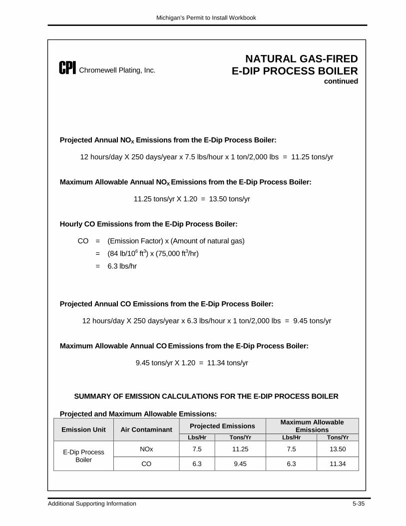
Michigan’s Permit to Install Workbook
Additional Supporting Information 5-35
NATURAL GAS-FIRED E-DIP PROCESS BOILER
continued Projected Annual NOX Emissions from the E-Dip Process Boiler:
12 hours/day X 250 days/year x 7.5 lbs/hour x 1 ton/2,000 lbs = 11.25 tons/yr
Maximum Allowable Annual NOX Emissions from the E-Dip Process Boiler:
11.25 tons/yr X 1.20 = 13.50 tons/yr
Hourly CO Emissions from the E-Dip Process Boiler:
CO = (Emission Factor) x (Amount of natural gas)
= (84 lb/106 ft3) x (75,000 ft3/hr)
= 6.3 lbs/hr
Projected Annual CO Emissions from the E-Dip Process Boiler:
12 hours/day X 250 days/year x 6.3 lbs/hour x 1 ton/2,000 lbs = 9.45 tons/yr
Maximum Allowable Annual CO Emissions from the E-Dip Process Boiler:
9.45 tons/yr X 1.20 = 11.34 tons/yr
SUMMARY OF EMISSION CALCULATIONS FOR THE E-DIP PROCESS BOILER
Projected and Maximum Allowable Emissions:
Emission Unit Air Contaminant Projected Emissions Maximum Allowable Emissions
Lbs/Hr Tons/Yr Lbs/Hr Tons/Yr
E-Dip Process Boiler
NOx 7.5 11.25 7.5 13.50
CO 6.3 9.45 6.3 11.34
CPI Chromewell Plating, Inc.
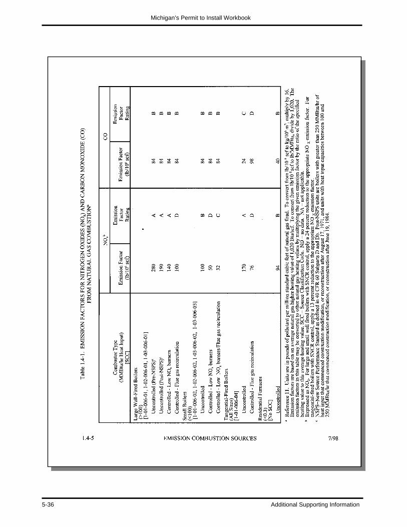
Michigan’s Permit to Install Workbook
5-36 Additional Supporting Information

Michigan’s Permit to Install Workbook
Additional Supporting Information 5-37
Mass Balance Mass balance is a method that estimates emissions by analyzing inputs of raw materials to an emission unit and accounting for all of the various possible outputs of the raw materials in the form of air emissions, wastewater, hazardous waste, and/or the final product (See Figure 5-9). As the term implies, one needs to account for all the materials going into and coming out of the emission unit for such emission estimation to be credible.
MASS BALANCE APPROACH
air emissions
raw materials product
hazardous wastewaste water
EMISSION UNIT
A mass balance approach can provide reliable average emission estimates for specific emission units. For some emission units, a mass balance may provide a better estimate of emissions than an emission test would. In general, mass balances are appropriate for use in situations where a high percentage of material is lost to the atmosphere (e. g., sulfur in fuel, or solvent loss in an uncontrolled coating process). The use of mass balance involves the examination of an emission unit to determine whether emissions can be estimated solely on knowledge of operating parameters, material compositions, and total material usage. The simplest mass balance assumes that all solvent used in a process will evaporate to become air emissions somewhere at the facility. For instance, for many surface coating operations, it can be assumed that all of the solvent in the coating evaporates to the atmosphere during the application and drying processes. In such cases, emissions equal the amount of solvent contained in the surface coating plus any added thinners. Mass balances are greatly simplified and very accurate in cases where all of the consumed solvent is emitted to the atmosphere. Situations occur in that a portion of the evaporated solvent is captured and routed to a control device such as an afterburner (incinerator) or condenser. In these cases, the captured versus fugitive portions must be measured or estimated by other means, and the disposition of any recovered material must be accounted for. As a second example, in degreasing operations, emissions will not equal solvent consumption if waste solvent is removed from the unit for recycling or incineration. A third example is where some fraction of the diluent (which is used to liquefy cutback asphalt, for example) is believed to be retained in the substrate (pavement) rather than evaporated after application. In these examples, a method of accounting for the non-emitted solvent is required to avoid an overestimation of emissions. Mass balances may be inappropriate where material is consumed or chemically combined in the process, or where losses to the atmosphere are a small portion of the total process throughput. As an example, applying mass balances to petroleum product storage tanks is not generally feasible because the losses are too small relative to the uncertainty of any metering devices. In these cases, emission factors can be used.
Figure 4-9: Mass Balance
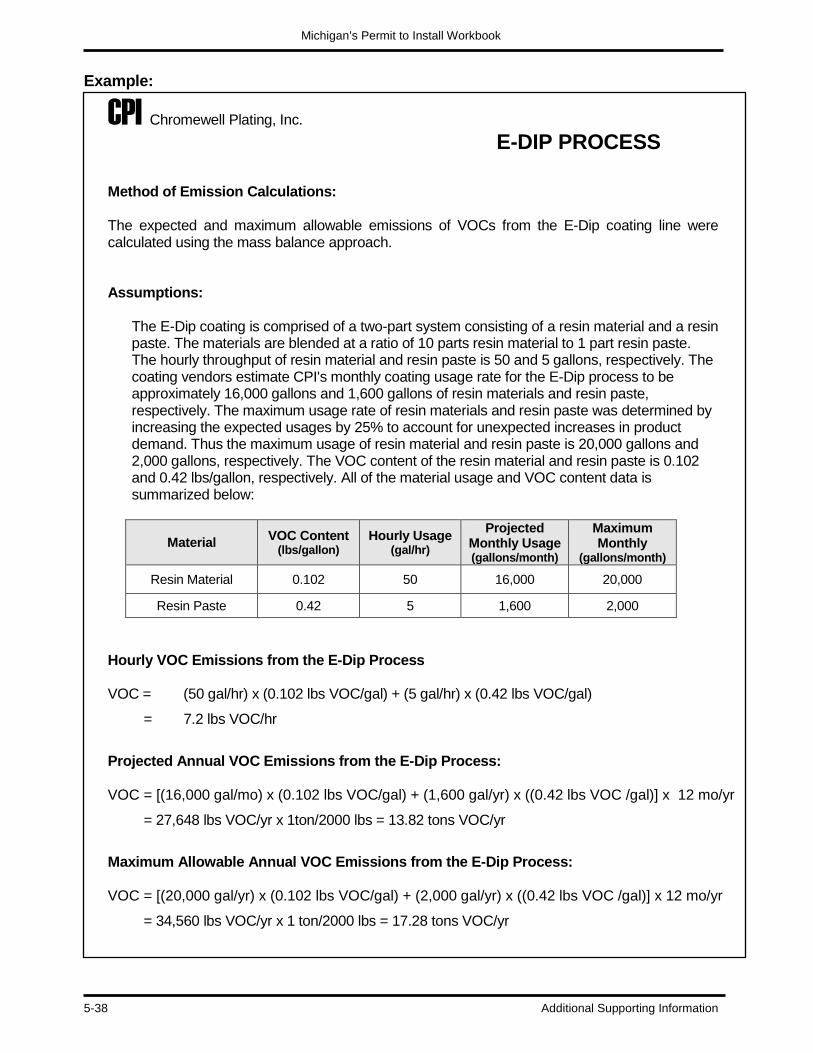
Michigan’s Permit to Install Workbook
5-38 Additional Supporting Information
Example:
CPI Chromewell Plating, Inc. E-DIP PROCESS
Method of Emission Calculations: The expected and maximum allowable emissions of VOCs from the E-Dip coating line were calculated using the mass balance approach.
Assumptions:
The E-Dip coating is comprised of a two-part system consisting of a resin material and a resin paste. The materials are blended at a ratio of 10 parts resin material to 1 part resin paste. The hourly throughput of resin material and resin paste is 50 and 5 gallons, respectively. The coating vendors estimate CPI's monthly coating usage rate for the E-Dip process to be approximately 16,000 gallons and 1,600 gallons of resin materials and resin paste, respectively. The maximum usage rate of resin materials and resin paste was determined by increasing the expected usages by 25% to account for unexpected increases in product demand. Thus the maximum usage of resin material and resin paste is 20,000 gallons and 2,000 gallons, respectively. The VOC content of the resin material and resin paste is 0.102 and 0.42 lbs/gallon, respectively. All of the material usage and VOC content data is summarized below:
Material VOC Content (lbs/gallon)
Hourly Usage (gal/hr)
Projected Monthly Usage (gallons/month)
Maximum Monthly
(gallons/month)
Resin Material 0.102 50 16,000 20,000
Resin Paste 0.42 5 1,600 2,000
Hourly VOC Emissions from the E-Dip Process VOC = (50 gal/hr) x (0.102 lbs VOC/gal) + (5 gal/hr) x (0.42 lbs VOC/gal)
= 7.2 lbs VOC/hr
Projected Annual VOC Emissions from the E-Dip Process: VOC = [(16,000 gal/mo) x (0.102 lbs VOC/gal) + (1,600 gal/yr) x ((0.42 lbs VOC /gal)] x 12 mo/yr
= 27,648 lbs VOC/yr x 1ton/2000 lbs = 13.82 tons VOC/yr
Maximum Allowable Annual VOC Emissions from the E-Dip Process: VOC = [(20,000 gal/yr) x (0.102 lbs VOC/gal) + (2,000 gal/yr) x ((0.42 lbs VOC /gal)] x 12 mo/yr
= 34,560 lbs VOC/yr x 1 ton/2000 lbs = 17.28 tons VOC/yr

Michigan’s Permit to Install Workbook
Additional Supporting Information 5-39
E-DIP PROCESS continued
SUMMARY OF EMISSION CALCULATIONS FOR THE E-DIP PROCESS
Projected and Maximum Allowable Emissions:
Emission Unit Air Contaminant Projected Emissions Maximum Allowable Emissions
Lbs/Hr Tons/Yr Lbs/Hr Tons/Yr
E-Dip Process Tank
VOC 7.2 13.82 7.2 17.28
CPI Chromewell Plating, Inc.

Michigan’s Permit to Install Workbook
5-40 Additional Supporting Information
Manufacturer’s Performance Tests A third, common approach to calculating the emission of air contaminants is the use of manufacturer’s performance tests. Vendors that sell process or control devices sometimes can supply their customers with emission test results for the equipment. Performance test results from established manufactures of process or control devices are, to a large degree, very accurate and credible. The test results are generated from emission monitoring systems or stack testing methods that measure the concentrations of the air contaminants in the exhaust stream from field tested emission units. Stack tests provide a means to determine the concentration of emissions of an air pollutant at the point of release. These tests are conducted according to established procedures. Stack tests provide a snapshot of emissions during the period of the test. Samples are collected using probes inserted into the stack. The probes collect pollutants in, or on, various filtering media which are either sent to a laboratory for analysis or analyzed on-site. Pollutant concentrations are obtained by dividing the amount of pollutant collected during the test by the volume of the air sampled. Stack tests predict a more accurate short-term emission rate than the mass balance approach. The use of performance tests from similar emission units is an acceptable means to determine emissions for proposed emission unit installations. However, the approved Permit to Install may require a stack test shortly after the new emission unit begins operation to verify the accuracy of the emission estimates.
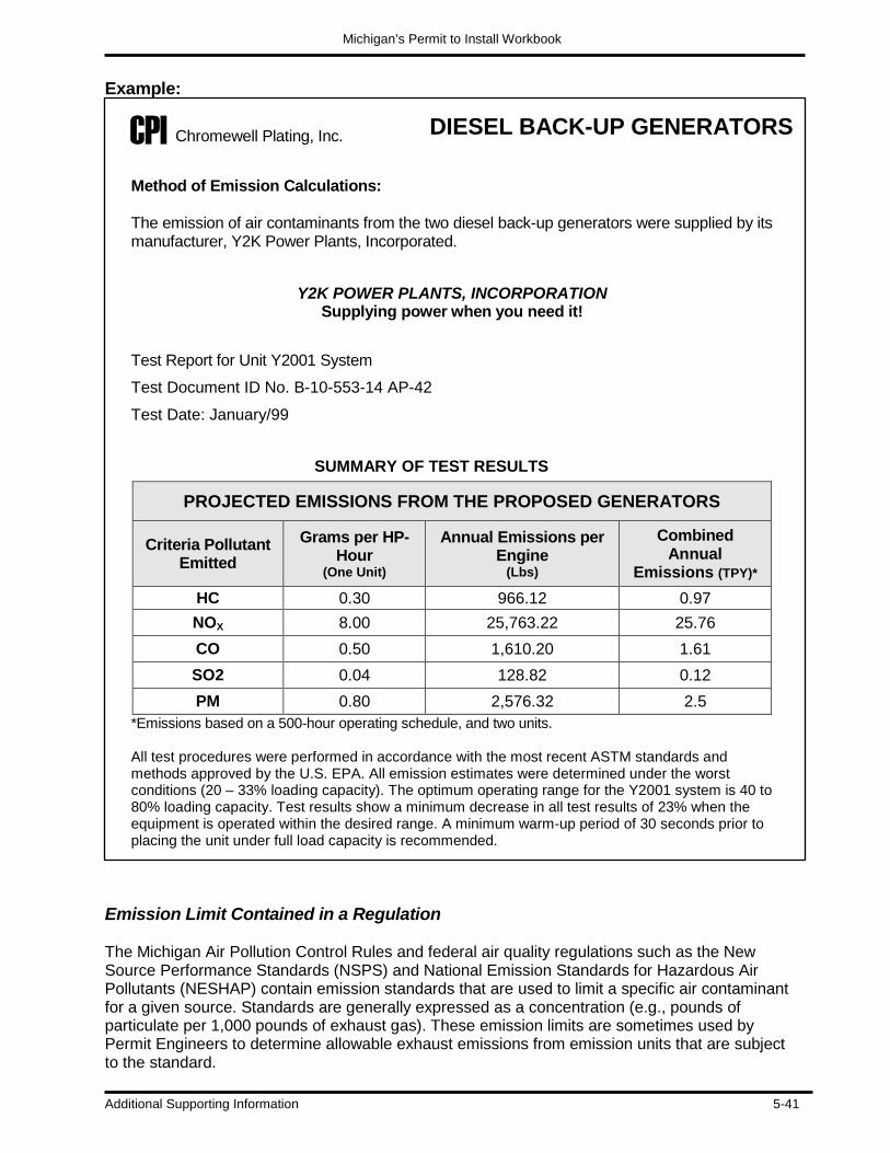
Michigan’s Permit to Install Workbook
Additional Supporting Information 5-41
Example:
DIESEL BACK-UP GENERATORS
Method of Emission Calculations: The emission of air contaminants from the two diesel back-up generators were supplied by its manufacturer, Y2K Power Plants, Incorporated.
Y2K POWER PLANTS, INCORPORATION
Supplying power when you need it!
Test Report for Unit Y2001 System
Test Document ID No. B-10-553-14 AP-42
Test Date: January/99
SUMMARY OF TEST RESULTS
PROJECTED EMISSIONS FROM THE PROPOSED GENERATORS
Criteria Pollutant Emitted
Grams per HP-Hour
(One Unit)
Annual Emissions per Engine
(Lbs)
Combined Annual
Emissions (TPY)* HC 0.30 966.12 0.97 NOX 8.00 25,763.22 25.76 CO 0.50 1,610.20 1.61 SO2 0.04 128.82 0.12 PM 0.80 2,576.32 2.5
*Emissions based on a 500-hour operating schedule, and two units. All test procedures were performed in accordance with the most recent ASTM standards and methods approved by the U.S. EPA. All emission estimates were determined under the worst conditions (20 – 33% loading capacity). The optimum operating range for the Y2001 system is 40 to 80% loading capacity. Test results show a minimum decrease in all test results of 23% when the equipment is operated within the desired range. A minimum warm-up period of 30 seconds prior to placing the unit under full load capacity is recommended.
Emission Limit Contained in a Regulation The Michigan Air Pollution Control Rules and federal air quality regulations such as the New Source Performance Standards (NSPS) and National Emission Standards for Hazardous Air Pollutants (NESHAP) contain emission standards that are used to limit a specific air contaminant for a given source. Standards are generally expressed as a concentration (e.g., pounds of particulate per 1,000 pounds of exhaust gas). These emission limits are sometimes used by Permit Engineers to determine allowable exhaust emissions from emission units that are subject to the standard.
CPI Chromewell Plating, Inc.

Michigan’s Permit to Install Workbook
5-42 Additional Supporting Information
Example:
DECORATIVE CHROME
PLATING LINE
Method of Emission Calculations: The expected and maximum allowable emissions of chrome from the decorative chrome plating line were calculated using the limit contained in the NESHAP for Chromium Emissions from Hard and Decorative Chrome Electroplating and Anodizing Tanks. Assumptions: Decorative chrome plating lines are subject to a NESHAP, which limits the concentration levels of chrome in the exhaust stream to 0.01 milligrams per cubic meter of exhaust gas (C mg/m3). The exhaust air flow of the scrubber is 2,000 dry standard cubic feet per minute (V dscfm). The scrubber will reduce the chromium emissions by 99.9%. In order to assure compliance with the vendors’ efficiency claim the company will use a 99% efficiency rating for the scrubber unit instead of the 99.9% claim. Maximum Allowable Chrome Emissions from the Decorative Chrome Plating Line:
ChromeMAX HR = C mg/m3 x V dscfm x 60 min/hr x 0.02832 m3/ft3 = lbs/hr
453.6 gram/lb X 1000 mg/gram
= (0.010) x (2,000) x 60 x 0.02832 = 7.49 x 10 –5 lbs/hr 453.6 x 1,000
Note: There is a NESHAP regulation for the decorative chrome plating process that sets a maximum allowable emission rate of 0.01 milligrams per cubic meter of exhaust for chromium emissions from the decorative chrome plating lines. The facility may negotiate to have the Permit Engineer set the emission limit to be the maximum allowable emission rate if it does not exceed the screening level. Otherwise, a value between the maximum allowable emission rate and the controlled emission limit may be used.
Maximum Allowable Annual Chrome Emissions from the Decorative Chrome Plating Line (as allowed by rule): ChromeMAX A = 24 hours/day X 365 days/year x 7.49 x 10 –5 lbs/hr = 0.656 lbs/yr* *Note: The annual emission rate is based upon a continuous (24 hour) operation in order to removes any operating restrictions on the process. On occasion jobs may be spread out over the day due to variations caused by demand, or system parameters may prolong the need to operate the control equipment.
CPI Chromewell Plating, Inc.
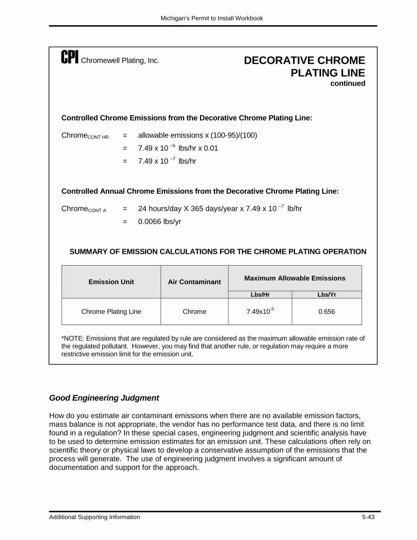
Michigan’s Permit to Install Workbook
Additional Supporting Information 5-43
DECORATIVE CHROME PLATING LINE
continued
Controlled Chrome Emissions from the Decorative Chrome Plating Line:
ChromeCONT HR = allowable emissions x (100-95)/(100)
= 7.49 x 10 –5 lbs/hr x 0.01
= 7.49 x 10 –7 lbs/hr
Controlled Annual Chrome Emissions from the Decorative Chrome Plating Line:
ChromeCONT A = 24 hours/day X 365 days/year x 7.49 x 10 –7 lb/hr
= 0.0066 lbs/yr
SUMMARY OF EMISSION CALCULATIONS FOR THE CHROME PLATING OPERATION
Emission Unit Air Contaminant Maximum Allowable Emissions
Lbs/Hr Lbs/Yr
Chrome Plating Line Chrome 7.49x10⁻⁵ 0.656
*NOTE: Emissions that are regulated by rule are considered as the maximum allowable emission rate of the regulated pollutant. However, you may find that another rule, or regulation may require a more restrictive emission limit for the emission unit.
Good Engineering Judgment How do you estimate air contaminant emissions when there are no available emission factors, mass balance is not appropriate, the vendor has no performance test data, and there is no limit found in a regulation? In these special cases, engineering judgment and scientific analysis have to be used to determine emission estimates for an emission unit. These calculations often rely on scientific theory or physical laws to develop a conservative assumption of the emissions that the process will generate. The use of engineering judgment involves a significant amount of documentation and support for the approach.
CPI Chromewell Plating, Inc.

Michigan’s Permit to Install Workbook
5-44 Additional Supporting Information
Example:
DECORATIVE CHROME PLATING LINE
Method of Emission Calculations: The hydrogen chloride (HCl) emissions from the acid tanks of the decorative chrome plating line were calculated using Fick’s Law. Assumptions:
• Hydrogen chloride (HCl) is received at a concentration of 35.2% by weight.
• HCl is used at a concentration of 7 to 11% by weight.
• The proposed source has an acid mist eliminatory control system.
• The tanks are operated at room temperature 25 OC (298 OK).
• The partial pressure for a 12% by weight solution of HCl at 25 OC is 0.0145 mmHg (1.9 x 10⁻⁵ atm).
• The gas constant (R) is 82.06.
• The diffusibilty (D) of HCl is half the value of water, which is 0.110 cm/sec.
• There are three tanks each with an area of 50 square (FT2).
• Operating schedule: 8 hours per day; 5 days a week; 50 weeks per year.
Determine the HCl Emissions Using Fick’s Law
Fick’s Law is as follows: N =
D x P R x T
N = the flux of the material diffusing across the liquid/air interface in gm/cm2-sec D = the diffusibility of the material P = the partial pressure R = the gas constant = 82.06 (atm x cm3) / (g∙mol x K) T = the temperature in Kelvin (K)
N = (0.110 cm/sec) x (1.9 x 10⁻⁵ atm) (82.06) x (298 K)
= 8.5 x 10⁻¹¹ gm/cm2-sec
CPI Chromewell Plating, Inc.
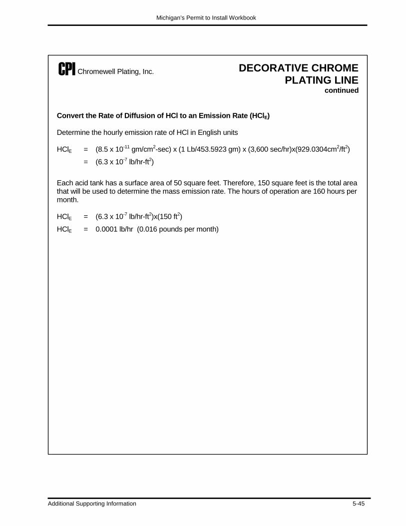
Michigan’s Permit to Install Workbook
Additional Supporting Information 5-45
DECORATIVE CHROME
PLATING LINE continued
Convert the Rate of Diffusion of HCl to an Emission Rate (HClE) Determine the hourly emission rate of HCl in English units HClE = (8.5 x 10⁻¹¹ gm/cm2-sec) x (1 Lb/453.5923 gm) x (3,600 sec/hr)x(929.0304cm2/ft2)
= (6.3 x 10⁻⁷ lb/hr-ft2)
Each acid tank has a surface area of 50 square feet. Therefore, 150 square feet is the total area that will be used to determine the mass emission rate. The hours of operation are 160 hours per month.
HClE = (6.3 x 10⁻⁷ lb/hr-ft2)x(150 ft2)
HClE = 0.0001 lb/hr (0.016 pounds per month)
CPI Chromewell Plating, Inc.

Michigan’s Permit to Install Workbook
5-46 Additional Supporting Information
WORKBOOK EXAMPLE No. 1 - Emission Factor (See Appendix E for Answers)
Problem:
Bill’s Special Foods is a food processing plant that has a natural gas-fired low-NOX process boiler with a heating capacity of 300 MMBtu/hr that is used primarily on their production line to process green beans. The line is operated 4,000 hours out of the year to process green beans, but it is also used as an auxiliary heating source for the meat packing line for another 2,000 hours. Calculate the projected and maximum allowable emissions of NOX, and CO from boiler using emission factors from AP-42, Table 1.4-1. (See page 5-37)
What are the assumptions that you need to know to determine the answer?
_______________________________________________________ _______________________________________________________ _______________________________________________________ _______________________________________________________ _______________________________________________________ _______________________________________________________ _______________________________________________________
_______________________________________________________
Calculate how much fuel the boiler will burn in an hour, and explain how this will help you determine the NOX and CO emissions:

Michigan’s Permit to Install Workbook
Additional Supporting Information 5-47
Determine the projected hourly NOX and CO emissions from the boiler: Determine the projected annual NOX and CO emissions from the boiler: Determine the maximum allowable annual NOX and CO emissions from the boiler (assume a 20 percent safety factor):

Michigan’s Permit to Install Workbook
5-48 Additional Supporting Information
Make a summary table of the projected and maximum allowable emissions. Projected Emissions:
Emission Unit Air Contaminant Projected Emissions
Lbs/Hr tons/Yr
Process Boiler NOX
CO
Maximum Allowable Emissions:
Emission Unit Air Contaminant Maximum Allowable Emissions
Lbs/Hr tons/Yr
Process Boiler NOX
CO

Michigan’s Permit to Install Workbook
Additional Supporting Information 5-49
WORKBOOK EXAMPLE No. 2 - Mass Balance (See Appendix E for Answers)
Problem:
Larry Blount owns over 65 auto refinishing plants in the Midwest. He is planning to build a new, state-of-the-art spray paint operation in Southeast Michigan. The spray paint operation will use an automated bell system that applies a uniform coating on automotive and truck surfaces. From past experience, he predicts that the new paint booth operation will have a coating usage of 7,000 gallons of topcoat material each year. They operate two 8 hour shifts, six (6) days a week, Monday through Saturday, and each shift has a one hour lunch period. The company also gives their employees two weeks of down time to celebrate major holidays. Mr. Blount’s experiences a business increase of 15 percent during the summer months, and he wants a permit that will allow his company a 10 percent growth for the next two years.
Calculate the projected and maximum allowable emissions of VOC from the coating operation using the mass balance approach. Use the material safety data sheets (MSDS) provided in this example.
GLOSS BLACK ELECTROSTATIC RESIN MATERIAL (P- 17PC) Section 4: Coating composition.
COMPOUND
% BY WEIGHT
CAS No.
2-Butoxy Ethanol 1 - 8 111-76-2 Carbon Black 4 - 11 1333-86-3
H.D. Epoxy PE Resin 9 - 23 Proprietary Titanium Oxide 7 - 17 2271-21-1
Water 10 - 15 Specific Gravity ....................................................................................................... 1.31 Percent VOC by weight .......................................................................................... 32.0 Percent Solids by weight ............................................................................................ 56
What are the assumptions that you need to know to determine the answer?
_______________________________________________________ _______________________________________________________ _______________________________________________________ _______________________________________________________ _______________________________________________________ _______________________________________________________

Michigan’s Permit to Install Workbook
5-50 Additional Supporting Information
Determine the projected annual VOC emissions from the coating line: Determine the projected hourly VOC emissions from the coating line: Determine the maximum allowable hourly VOC emission rate for the coating line:

Michigan’s Permit to Install Workbook
Additional Supporting Information 5-51
Determine the maximum allowable annual VOC emission rate for the coating line: Make a summary table of the projected and maximum allowable emissions.
Emission Unit Air Contaminant Projected Emissions
lbs/hr tons/yr
Emission Unit Air Contaminant Maximum Allowable Emissions
lbs/hr tons/yr

Michigan’s Permit to Install Workbook
5-52 Additional Supporting Information
Regulatory Discussion
Every application should contain a discussion of which regulations apply and include a description of the methods that will be used to comply with those requirements. The regulatory review discussion should contain an identification of all of the state and federal air quality regulations applicable to the particular emission unit(s) identified in the Permit to Install application. Based upon the other information provided in the application, such as the emission unit description and the type and quantity of air contaminants emitted, you should be able to identify the applicable regulations and determine your facility’s ability to operate in compliance with those requirements. Do not assume that whatever you are originally proposing to install will receive an approved Permit to Install. After reviewing the applicable regulations, you may have to make changes to your original Permit to Install application submittal in order to comply with the requirements, many of which include air pollution control devices or the use of low air polluting raw materials. The regulatory discussion lays the framework for the terms and special conditions of the approved Permit to Install. Once the Permit to Install is issued, it is your responsibility to demonstrate compliance with all of the conditions of the Permit to Install. Many Applicants have difficulty in identifying all of the state and federal rules that apply to their emission unit(s). The large number, complexity, and the Applicant’s unfamiliarity with the regulations are some of the reasons why this important information is often excluded from the Permit to Install application. Your application will be better, more complete, and more likely to gain approval if you properly identify the rules that apply. The applicability of a specific air regulation can depend upon one or more of the following factors:
• Type of pollutant emitted (VOCs, particulate, hazardous air pollutant). • Emission rate of pollutant (pounds/hour, tons/year). • Type of emission unit (degreaser, hot mix asphalt plant). • Installation date of the emission unit.
For example, the annual emission rate, type of pollutant, and the emission unit type can determine if an emission unit is subject to federal or state requirements. However, emissions that are subject to a federal requirement may have one or more state requirements that must be satisfied as well, and vise versa. Most state requirements target a specific pollutant, while the majority of federal air regulations are written for a specific type of emission unit. The following is a summary of the state and federal air quality regulations that may be applicable to the emissions units identified in your Permit to Install application. The Michigan Air Pollution Control Rules can be found at www.michigan.gov/air (click on “News and Info” then “State Air Laws and Rules” then “Air Pollution Control Rules”). All federal regulations are published in the Code of Federal Regulations (CFR) which, along with air quality regulations, can be accessed at www.epa.gov/lawsregs/regulations . The federal regulations that apply to sources of air pollution are the NESHAP and NSPS programs and the major source review requirements. By no means is the following regulatory overview inclusive of all of the state and federal applicable regulations.
Michigan’s Permit to Install Workbook
Additional Supporting Information 5-53
State Regulations The AQD has promulgated numerous regulations to control the emissions of air contaminants. The purpose of the rules is to help Michigan attain, or to keep Michigan in attainment, with the National Ambient Air Quality Standards (NAAQS). The U.S. EPA has set standards for six air contaminants: ozone, particulate matter less than 10 microns in diameter, sulfur dioxide, nitrogen dioxide, lead, and carbon dioxide. Adverse effects to human health and the environment can occur when the concentration of these pollutants exceeds or is in nonattainment of the standard. The rules promulgated under Part 55 of Act 451, the Michigan Air Pollution Control Rules, are grouped into parts. The Michigan Air Pollution Control Rules can be found at www.michigan.gov/air (click on “News and Info” then “State Air Laws and Rules” then “Air Pollution Control Rules”). Part 1: Definitions The Part 1 rules do not contain regulations. However, important terms such as potential to emit are defined in this part of the rulebook. You will need to reference the Part 1 rules when reviewing and interpreting the regulations that follow. Part 2: Air Permitting and Air Toxics The two state air permitting requirements, Permit to Install and the Renewable Operating Permit (ROP), are found in the Part 2 rules. In addition, the Part 2 rules contain the rules that regulate the emission of toxic air contaminants. Permit to Install According to Rule 201 of the Michigan Air Pollution Control Rules, before a facility can legally install, relocate, modify, or reconstruct equipment that emits air contaminants, it must apply for and receive an approved Permit to Install. Not all sources of air contaminants or emission units need to be permitted under Rule 201. Part 2 contains numerous rules exempting insignificant sources of air pollution from having to apply for a Permit to Install. Renewable Operating Permit It is important not to confuse the Permit to Install with Michigan’s other air permit requirement: the Renewable Operating Permit (ROP). The ROP originated from Title V of the Clean Air Act Amendments of 1990. The ROP program clarifies which requirements apply to a facility that emits air contaminants. These obligations are scattered among numerous state and federal regulations. The ROP incorporates all requirements into a single document that gives the facility, state and local regulatory agencies, the U.S. EPA, and the public a clearer picture of the pollutants being emitted from a facility. Facilities that meet the definition of “major source” must obtain a ROP. The U.S. EPA has also required all acid rain and waste incineration facilities to obtain a ROP even if they are below the major source cutoffs. The ROP program does not supersede or replace the Permit to Install requirements. Sources having to apply for a ROP are still required to submit a Permit to Install application when installing or modifying emission units. All Permit to Install conditions are eventually folded into the facility’s ROP.

Michigan’s Permit to Install Workbook
5-54 Additional Supporting Information
Air Toxics Regulations In Michigan, air toxics are controlled under two sets of regulations: (1) state administrative rules, which regulate toxic air contaminants or TACs; and (2) the federal Clean Air Act, which regulates the release of hazardous air pollutants. Part 3: Particulate Matter Part 3 rules establish particulate emission limitations for various emission units. Open burning and the density of visible emissions from a vent or stack are regulated as well. Certain facilities must develop plans to control fugitive dust emissions from roadways, storage piles, and other dust-generating activities. Rule 331 contains maximum allowable emission rates of particulate matter from a variety of emission units, such as fuel-burning equipment, incinerators, steel manufacturing, foundries, kilns, asphalt paving plants, cement manufacturing, iron ore pelletizing, fertilizer plants, and exhaust systems serving material handling equipment not otherwise identified. The majority of emission rates are expressed in pounds of particulate emitted per 1,000 pounds of exhaust gas. Opacity is defined as the degree to which air emissions reduce the transmission of light and is measured as a percentage. For example, if the opacity of air contaminants being discharged from a stack is 20 percent, then 20 percent of the light traveling through the plume is blocked by the air emissions and 80 percent of the light passes through the plume. In other words, the higher the opacity being observed, the denser the plume of air emissions. Rule 301 limits the opacity of visible emissions discharged from an emission unit. This rule prohibits facilities from discharging dense black or white smoke from their activities. Fugitive dust control programs that are incorporated into the special conditions of a Permit to Install are the most widely used mechanisms to control fugitive dust sources. Rule 371 gives the AQD the authority to require a fugitive dust control program. Rule 372 lists the required actions that shall be used to control fugitive dust from the various fugitive dust generating activities such as open storage piles, material conveyors, unpaved roads and lots, and construction activities. A section of each fugitive dust control program should address the collection and disposal of air contaminants. Rule 370 states that the collection and disposal of air contaminants shall be performed in a manner that minimizes the introduction of contaminants into the outer air. Part 4: Sulfur Bearing Compounds Part 4 rules of the Michigan Air Pollution Control Rules establish sulfur dioxide emission limitations on boilers and other fuel-burning equipment. The sulfur content of fuels, such as coal and fuel oil, must fall within prescribed percentages. Part 6: Existing Sources of VOC Emissions In 1978, the U.S. EPA published a document containing available methods and technologies designed to reduce emissions from a variety of sources that emit VOCs. Many of the control strategies in this document were incorporated into the Michigan Air Pollution Control Rules, specifically the Part 6 rules (see Table 5-4). The U.S. EPA document describes the technologies as reasonable available control technology (RACT). RACT was developed to help state and local agencies determine the level of VOC control needed to represent the lowest achievable emission rate using reasonable available control technology. Significant research was conducted to establish RACT and identify a level of

Michigan’s Permit to Install Workbook
Additional Supporting Information 5-55
control that industry could comply with, while benefiting the environment through improved air quality. Part 6 rules are often referred to as the RACT rules, and they are used to regulate existing sources of VOCs in accordance with state obligations under the federal Clean Air Act. Table 5-4: Summary of Part 6 Rules
Rule Number VOC Source Existing Means
Equipment Installed Before
604-605 Storage of organic compounds July 1, 1979 606-609 Loading of gasoline into gas stations and bulk plants July 1, 1979
610 Automotive and light-duty trucks, cans, coils, large appliances, metal furniture, magnet wire, and non-metallic surfaces of fabrics, vinyl, or paper coating lines
July 1, 1979
611-614 Solvent vapor degreasers and cold cleaners July 1, 1979 615-617 Petroleum refinery July 1, 1979
618 Cutback paving asphalt July 1, 1979 619 Perchloroethylene dry cleaning equipment July 1, 1980 620 Flat wood paneling lines July 1, 1980 621 Metallic surface coating lines July 1, 1980 622 Petroleum refineries July 1, 1980 623 Storage of petroleum liquids July 1, 1980 624 Graphic artist lines July 1, 1980 625 Pharmaceutical products July 1, 1980 627 Delivery vessels Not applicable 628 Synthetic organic chemicals January 5, 1981 629 Natural gas processing January 20, 1984 630 Paint manufacturing July 1, 1987 631 Polystyrene and organic resins July 1, 1987 632 Plastic coating lines July 1, 1979 660 Consumer Products October 3, 2007
Part 7: New Sources of VOC Emissions Under the Part 7 rules, a “new source” is defined as any emission unit which is either placed into operation on or after July 1, 1979, or for which a Permit to Install application is made, except for any emission unit which is an “existing source” as defined in Rule 601. According to Rule 702, when installing a new source of VOCs or modifying an existing source, a facility must evaluate the following four emission rates and use whichever one results in the lowest maximum allowable emission rate of VOCs.
1. An emission rate based upon best available control technology (BACT). 2. The maximum allowable emission rate specified by a NSPS promulgated by the U.S. EPA. 3. The maximum allowable emission rate specified as a condition of a Permit to Install. 4. The maximum allowable emission rate specified in the Part 6 rules of the Michigan Air
Pollution Control Rules. BACT Analysis
Michigan’s Permit to Install Workbook
5-56 Additional Supporting Information
Best Available Control Technology (BACT) is an emission limitation based on the maximum degree of reduction that has either been achieved in practice for a category of processes, is found in other state air quality rules, or is considered by the regulatory agency to be technically feasible and cost effective. A BACT analysis, which is performed as part of the permit review process, triggers continual use of technology that results in low emissions of air contaminants. Since technology is ever-changing, BACT is an evolutionary process that strives for continuous improvement of air quality in the state. A top-down method is used to determine BACT. Top-down refers to evaluating and considering the control options that provide the most reduction in emission of air contaminants before considering those offering less emission reductions. The top-down analysis can be divided into five steps. All five steps require extensive documentation. Step 1: Identify all coatings, application equipment, and add-on pollution control devices available to the process and air contaminants under evaluation. For surface coating lines, add-on control devices to consider include regenerative and recuperative thermal and/or catalytic oxidizer, carbon adsorption, and any of the above in combination with a concentrator such as a carbon wheel. All of the following sources of information would generally need to be investigated to ensure that all possible control strategies are identified: technical literature; industrial surveys; the RACT/BACT/LAER Clearinghouse (which is a bulletin board on the U.S. EPA’s Technology Transfer Network [TTN] located at www.epa.gov/ttn); and federal, state, and local air pollution control agency surveys. Step 2: Evaluate the technical feasibility of the control options. Technically unfeasible control options are eliminated from further consideration in the BACT analysis if a detailed description regarding why they are technically unfeasible is included. Step 3: All control technologies not eliminated in Step 2 are ranked in order of overall control effectiveness for the pollutant under review, with the most effective control alternative at the top. Step 4: Starting at the top, consider the economic, environmental, and energy impacts. If the impacts indicate that the most stringent technology is not achievable, then the next most stringent control becomes the new control candidate and is similarly evaluated. The process continues until the technology under consideration cannot be eliminated by specific environmental, energy, or economic impacts. The following are examples of when energy, economic, or environmental impacts may make an alternative unfeasible. Energy: natural gas for operating an afterburner not available based on local
regulations. Economic: the increased cost of the final product would make the project no longer
feasible.
Environmental: a wet scrubber may create a by-product which cannot be disposed of without creating a more detrimental impact.
Step 5: The most effective control option not eliminated under Step 4 is proposed as BACT for the air contaminant and process under review. The decision to require add-on pollution control equipment is determined on a case-by-case basis. The Air Quality Division uses a general rule of thumb to determine the economic feasibility of requiring the installation of an add-on control device. If the cost of control per ton of air contaminant is more than $6,000, Permit Engineers usually consider the cost as being not economically feasible. This figure considers capital equipment investment, labor cost, maintenance cost, fuel cost, retro-fit

Michigan’s Permit to Install Workbook
Additional Supporting Information 5-57
costs, and other associated costs. Keep in mind that this figure is only a rule of thumb. Higher costs, in some cases, will be considered cost effective. For assistance in the completion of a BACT analysis, the U.S. EPA’s Office of Air Quality Planning and Standards has created an electronic file entitled, “Co$t-Air Control Cost Spreadsheets.” The file, co$t-air.zip, contains a set of 20 spreadsheets that make calculations of capital and other costs for add-on control devices much easier, more flexible, and more accurate than other methods. The file can be accessed from the U.S. EPA, Clean Air Technology Center’s (CATC) home page. The CATC’s home page is part of the U.S. EPA’s Technology Transfer Network site. The Internet address is www.epa.gov/ttn/catc. New Source Performance Standards Under Section 111 of the Clean Air Act, the U.S. EPA is authorized to establish new source performance standards (NSPS) for new or modified sources in particular industrial categories. These standards set emission limits for over 75 categories. The NSPS requirements are found in the federal rules published in the Code of Federal Regulations (CFR). The federal rules relating to environmental protection are contained in Title 40 of the CFR. Air quality regulations are found in Parts 50 to 99 of Title 40. The NSPS requirements are located in Part 60. Each specific NSPS is a subpart of Part 60. A listing of NSPS subparts can be found at www.tceq.state.tx.us/permitting/air/rules/federal/60/60hmpg.html. Permit Conditions An emission rate contained in a previously issued Permit to Install is reviewed by the Permit Engineer and applied to a similar new source undergoing the permit review. From a practical standpoint, this emission rate is not viable as it would be difficult to limit emissions by permit condition to a level more stringent than prescribed by BACT. Finally, the last step to identify the lowest maximum allowable emission rate for a proposed new source of VOC emissions is the emission limitations contained within the Part 6 rules of Michigan Air Pollution Control Rules. It is a reasonable expectation that new sources of VOCs should emit no more than existing sources of VOCs. Part 8: Emission Limitations for Oxides of Nitrogen The Part 8 rules limit the emission of nitrogen oxide from fossil fuel and gas-fired combustion devices. The following emission units are subject to Part 8 rules: • A fossil fuel-fired, electricity-generating utility unit which has the potential to emit more than
25 tons of nitrogen oxides each ozone season and which serves a generator with a capacity of 25 megawatts or more.
• A fossil fuel-fired emission unit which has the potential to emit more than 25 tons of nitrogen oxides each ozone season and which has a maximum rated heat input capacity of more than 250 million British thermal units per hour.
Process boilers, electric power generation units, internal combustion engines, gas-fired turbines, and other process heater units are examples of emission units that could be subject to the Part 8 rules.

Michigan’s Permit to Install Workbook
5-58 Additional Supporting Information
Part 9: Miscellaneous The rules in Part 9 of the Michigan Air Pollution Control Rules can apply to any facility, regardless of the type of air contaminant emitted or emission unit installed. According to Rule 901, air contaminants cannot be emitted in quantities that could have an injurious effect on human health or safety or cause unreasonable interference with the comfortable enjoyment of life and property. Facilities, upon request from the AQD, must prepare a malfunction abatement plan to prevent, detect, and correct malfunctions resulting in the emissions of air contaminants exceeding any applicable limitation (Rule 911). The malfunction abatement plan can be incorporated into the special conditions of the Permit to Install. When a manufacturer has a malfunction of a process device and/or control device that results in the exceedance of an emission standard or limitation over a prescribed amount of time, it must be reported to the AQD (Rule 912). Part 10: Intermittent Testing and Sampling Part 10 rules give the AQD authority to require sources to quantify their air emissions to verify compliance with the emission standards. The testing must be performed in accordance with established testing methodologies. Testing requirements may be incorporated into the special conditions of the Permit to Install. Part 11: Continuous Emission Monitoring Large sources of air contaminants must operate continuous emission monitoring equipment to verify compliance with the applicable emission standards. The monitoring equipment is typically installed in the process device itself or in the stack. Continuous emission monitoring may be incorporated into the special conditions of the Permit to Install. Federal Air Regulations The U.S. EPA promulgates federal rules and standards that affect a wide variety of sources of air contaminants. The DEQ, AQD receives delegation from the U.S. EPA to implement and enforce compliance with these federal regulations. Some of the federal air quality regulations that all facilities should be aware of include: major source review in attainment and nonattainment areas, New Source Performance Standards (NSPS), National Emission Standards for Hazardous Air Pollutants (NESHAPs), and Risk Management Plans. Major Source Review in Attainment Areas - Prevention of Significant Deterioration (PSD) Facilities that submit a Permit to Install application for a proposed new source or a proposed modification of an emission unit at an existing source need to be aware of the federal PSD requirements. Michigan implements these requirements through the Part 18 rules, which mirror the federal requirements. Applications for a "major PSD source" or "major PSD modification" are subject to the PSD requirements. To be subject to PSD, a proposed new source must have the potential to emit of any regulated air pollutant greater than 100 or 250 tons per year (depending on source category). At an existing PSD major source, a proposed new source or emission unit is subject to PSD if it emits an air contaminant for which the area is in attainment of the NAAQS and

Michigan’s Permit to Install Workbook
Additional Supporting Information 5-59
both the increase and the net increase of that particular air contaminant’s emissions are above the pollutant’s significant emission threshold level. See the “PSD Workbook” for a more detailed explanation of PSD applicability. The goal of the PSD program is to ensure that areas in compliance with the NAAQS remain in compliance with the standard. For this goal to be realized, the sources of air pollution subject to PSD need to meet stringent control requirements known as best available control technology (BACT). A definition of BACT is found on page 5-62. The federal PSD regulations are found in Title 40, Part 52, of the Code of Federal Regulations (40 CFR 52), and the state rules are in Part 18 of the Rules for Air Pollution Control. If you are constructing a source or installing or modifying emission units that are subject to PSD, you are encouraged to hire a consultant to help you comply with all of the complex PSD requirements. Discussion of all the necessary information that must be included in a Permit to Install application for a PSD source is beyond the scope of this workbook. Major Source Review in Nonattainment Areas Facilities that submit a Permit to Install application for a proposed new major source or a major modification of a nonattainment pollutant need to be aware of the requirements for major source review in nonattainment areas. Michigan implements these requirements through the Part 19 rules, which mirror the federal requirements. To be subject to Part 19, a new source must have the potential to emit a nonattainment pollutant greater than 100 tons per year. At an existing major source of a nonattainment pollutant, a proposed new source or emission unit is subject to Part 19 review if it emits a nonattainment pollutant at a level greater than the pollutant’s significant threshold level and the project’s net emissions increase is also above the pollutant’s significant threshold level. The goal of major source review in nonattainment areas is to improve the quality of air in areas that are not meeting the NAAQS for a particular air contaminant, while still allowing the installation of new sources that emit air contaminants. For this goal to be realized, sources subject to the Part 19 requirements need to meet stringent control requirements known as lowest achievable emission rate (LAER) and the emission of the proposed air contaminant must be offset by a decrease in the same air contaminant from existing sources. LAER is defined in Rule 1901 as the most stringent emission limit contained in any states’ rules unless the facility can demonstrate that the limit is not achievable. LAER can also be the most stringent limit achieved by another similar facility. If your application submittal is subject to these complex requirements, you may want to hire a consultant to help with the preparation of the Permit to Install application. Demonstrating compliance with the Part 19 requirements in the Permit to Install application is beyond the scope of this workbook. National Emission Standards for Hazardous Air Pollutants (NESHAPs) The 1970 version of the federal Clean Air Act required the U.S. EPA to set emission standards referred to as National Emission Standards for Hazardous Air Pollutants, or NESHAPs. From 1970 to 1990, NESHAPs were issued for only seven compounds: asbestos, beryllium, mercury, vinyl chloride, arsenic, radionuclides, and benzene. Under Title III of the Clean Air Amendments of 1990, Congress required the U.S. EPA to speed up the pace of regulation. Section 112 of the Clean Air Act Amendments called for the development of NESHAPs to reduce the emissions of 188 hazardous air pollutants (HAPs). The original list of HAPs contained 189 compounds; however, the list continues to be amended and the number of regulated HAPs will vary.
Michigan’s Permit to Install Workbook
5-60 Additional Supporting Information
Source Categories of HAPs Implementation of Section 112 began with the identification of sources that are the major contributors of HAP emissions. The U.S. EPA has identified over 174 source categories of sources that emit HAPs and which should be regulated. Since the regulation of all these sources would require huge time and resource commitments, the 1990 Clean Air Act Amendments created a schedule for the development of the NESHAPs to be phased in over a period of 10 years, with standards for all types of sources scheduled to have been completed by the year 2000. While the U.S. EPA has now promulgated standards for nearly every one of them, a few remain incomplete. “Residual Risk” Review Section 112(f) of the 1990 Clean Air Act Amendments required that the U.S. EPA, after promulgating initial standards based on control technology, to review the remaining risk at the sources regulated. The U.S. EPA may promulgate additional requirements to reduce this remaining, or “residual” risk. EPA has promulgated several such standards, and is continuing to review the remaining source categories. Major and Area HAP Sources Defined A "major source of HAPs" is a facility with a potential to emit (PTE) of 10 tons or more per year of any single HAP or 25 tons or more per year of all HAPs combined. An "area source" is one with a PTE less than 10 tons per year of any single HAP and less than 25 tons per year of all HAPs combined. The vast majority of NESHAPs being promulgated apply to major HAP sources. NESHAPs have been and are being promulgated for both major and area sources. Regulating Major and Area HAP Sources - MACT and GACT Section 112 of the federal Clean Air Act requires the U.S. EPA to promulgate regulations that establish emission standards (commonly referred to as NESHAPs) for each category of major sources and area sources of HAPs identified in their schedule of regulation promulgation. The standards for major sources of HAPs must require the maximum degree of emission reduction that the U.S. EPA determines to be achievable by each particular source category. This standard is referred to as the maximum achievable control technology, or (MACT) for short. MACT levels can be different for existing and new sources. The U.S. EPA determines what kind of controls qualify as the "maximum control" for each category of HAP sources. For source categories with at least 30 sources nationwide, MACT must be no less stringent than the average emission rate achieved by the best performing 12 percent of existing sources. Maximum achievable control technology ensures that both new and existing major sources of toxic air pollution use the kind of technology that provides maximum control of HAPs on an ongoing basis. The terms NESHAP and MACT are often used interchangeably. Area sources may require either MACT or Generally Available Control Technology (GACT). GACT standards are less stringent than MACT. All of the promulgated MACTs are found in subparts of Title 40, Part 63, of the Code of Federal Regulations. A listing of the major source and area source MACT categories can be found at www.epa.gov/ttn/atw/mactfnlalph.html. Schedule for Compliance with the NESHAPs New sources (i.e., sources that commence construction or reconstruction after proposal of the NESHAPs) must comply with the standard immediately upon start-up, with one exception. Sources constructed or reconstructed after the NESHAPs proposal, but before promulgation,
Michigan’s Permit to Install Workbook
Additional Supporting Information 5-61
must comply with the promulgated standard within three years of promulgation. Existing sources (i.e., sources in operation prior to the proposed standard) have three years from the promulgation date to comply with the NESHAP. What Happens if the U.S. EPA Doesn't Meet the Schedule? The 1990 Amendments of the Clean Air Act also recognized that the U.S. EPA might not be able to promulgate all of the source-specific NESHAPs within the time specified. Section 112(j) of the Clean Air Act ensures control of HAP emissions even if the U.S. EPA should miss a scheduled NESHAPs promulgation date. If the U.S. EPA misses a scheduled promulgation date by 18 months, major sources in that category must submit to their respective state (or local) agencies a permit application proposing source-specific MACT which is at least as stringent as the MACT standard that the U.S. EPA would have issued. Section 112(j) is commonly referred to as the "MACT hammer" because of the potential liability it opens up to all facilities. Construction or Reconstruction of a Major Source According to Section 112(g) of the Clean Air Act, if you are proposing to construct or reconstruct (Section 112(g) does not apply to modifications) a major HAP source, and this particular source category is not subject to a promulgated NESHAP, then your facility must submit a Permit to Install application which includes a case-by-case MACT determination. The DEQ must include a 30-day public review comment period before issuing the permit. If EPA promulgates a NESHAP for the source category after the issuance of the permit, the facility needs to comply with the new standard as expeditiously as practical, but no longer than eight years after the standard is promulgated. Additional NESHAPs Information For more complete information on NESHAPs, log on to the U.S. EPA's Air Toxics Website at www.epa.gov/ttn/atw . It contains a wealth of information concerning all the existing and proposed NESHAPs developments. To obtain copies of the NESHAPs as they appear in the Code of Federal Regulations rules, go to www.ecfr.gov/cgi-bin/text-idx?tpl=/ecfrbrowse/Title40/40tab_02.tpl. Comparison of Federal and Michigan Air Toxics Rules Michigan's air toxics rules apply independently of any federal Clean Air Act regulations. However, Michigan’s air toxics rules defer to promulgated NESHAP in some ways. See pages 5-74 and 5-75 for more information.

Michigan’s Permit to Install Workbook
5-62 Additional Supporting Information
Table 4-5: Comparison of Federal and Michigan Programs
Federal Clean Air Act Amendments Michigan Air Toxics Rules
Applies to new or modified sources of air toxics?
Yes Yes
Applies to existing sources of air toxics?
Yes No
Which air toxics are regulated?
At present, 188 chemicals known as hazardous air
pollutants or HAPs (the list is subject to change)
All substances other than 41 specifically exempted compounds. These regulated contaminants are known as toxic air contaminants or
TACs.
Effective date of regulations Various – as promulgated In effect now
Types of controls required Maximum achievable controls Best Available Controls, and health-based screening levels
New Source Performance Standards New Source Performance Standards (NSPS) are federal requirements applicable to over 75 categories of industrial emission units. The U.S. EPA developed these standards to ensure that old sources of air pollution would be replaced with less polluting technology, thus having a net benefit to air quality. Not only does the installation of certain new emission units after a specific date trigger applicability with the NSPS, changes to your existing emission units could subject you to the standards. Changes are defined in terms of modifications and reconstruction. Modification is defined as "any physical or operational change to an existing emission unit which results in an increase in emissions to the atmosphere of any pollutant to which a standard applies." If the fixed capital cost of the changes you make to your emission unit is more than 50 percent of the fixed capital costs required to construct a comparable emission unit, your facility has been "reconstructed" under the NSPS definition. For example, if you replaced the dryer portion of an asphalt plant, you would need to compare the cost of the new dryer to the cost of an entirely new asphalt plant as defined in the NSPS for Hot Mix Asphalt Facilities to determine if your changes fall under the definition of reconstruction. All of the NSPS are located in Title 40, Part 60, of the Code of Federal Regulations. Each regulation is identified in a subpart of Part 60. A listing of NSPS subparts can be found at www.tceq.state.tx.us/permitting/air/rules/federal/60/60hmpg.html The NSPS applies to emission units constructed, modified, or reconstructed after the effective date of the standard. It is important that you understand the definitions of an affected facility under NSPS before you install, modify, or reconstruct sources of air pollution so that you will be able to comply with all of the pertinent emission limits, record keeping, reporting, and other operational requirements in the NSPS.

Michigan’s Permit to Install Workbook
Additional Supporting Information 5-63
Additional Sources of NSPS Information The actual regulations in their entirety can be downloaded from U.S. EPA's Website at www.ecfr.gov/cgi-bin/text-idx?tpl=/ecfrbrowse/Title40/40tab_02.tpl. You can also get help by calling the Office of Environmental Assistance at 800-662-9278. Managing Chemical Risk: Accidental Release/Risk Management Plan On June 21, 1999, companies of all sizes that use certain listed chemicals were required to submit plans that detail how they will prevent accidental chemical releases from occurring. This compliance requirement is known as the Accidental Release/Risk Management Program of the 1990 Clean Air Act Amendments. It is Section 112(r) of the Clean Air Act. The goal of this regulation is to communicate potential risks to the public and ensure that facilities have implemented baseline internal management structure, safety and prevention, and emergency response programs to reduce the possibility of an accidental release. The primary tool used to accomplish this goal is the Risk Management Plan (RMP). A facility must develop a RMP if they have regulated substances (comprised of toxic chemicals and flammables) identified under Section 112(r) at or above a specific threshold quantity that is set for each substance. Size of the company does not determine applicability; a business is required to complete a RMP if the type and quantity of chemicals used are listed as regulated substances. There are three levels of compliance with Section 112(r) called "Programs." Facilities that have a process that uses, stores, manufactures, processes, or handles or transports on-site a Section 112(r) regulated substance over the threshold quantity, are required to conduct some level of accidental release "Program" planning. Program 1 is the most lenient while Program 3 is the most stringent. The Programs are comprised of four major components:
1. A Hazard Assessment, including the modeling of a worst case and alternative accidental chemical release.
2. Establishment of a Management Program (who's in charge of the RMP).
3. A Prevention Program to minimize the potential occurrence of an accidental release.
4. An Emergency Response Program to protect public health and the environment.
Program 1, 2, or 3 applicability dictates with which of these requirements a facility must comply. Facilities subject to Section 112(r) must meet their Program compliance requirements by June 21, 1999, or at the time that a substance is first present at their facility.

Michigan’s Permit to Install Workbook
5-64 Additional Supporting Information
Example:
REGULATORY REVIEW SUBMITTED BY CHROMEWELL PLATING, INC.
Introduction There are four proposed emission units at this site that are subject to Michigan Air Pollution Control Rule 201 and, therefore, are required to be permitted. These emission units consist of one electrostatic deposition (E-Dip) process, two diesel-fired back-up generators, and a decorative chrome plating line. The emission calculation section, as well as the emission summaries show, that this installation is a true minor source, and not subject to any federal programs such as PSD or major source review for nonattainment areas. However, the decorative chrome plating line will be subject to a National Emission Standard for Hazardous Air Pollutants (NESHAP). E-Dip The E-Dip coating line is a new installation and is used to apply performance coatings to metal parts for the automotive industry. The E-Dip line has the capability of using more than 200 gallons per month of coating materials and, therefore, cannot be exempt under Rule 287. The coating line is subject to Rule 702, which requires BACT for new VOC sources. Generally, top-down-BACT should be performed on all VOC sources, but it is more practically applied to sources that have VOC emissions that approach the significant level for VOC (40 tons per year). The process would follow the same steps by looking at the design, VOC tonnage, percent capture of the pollutant, feasibility for control equipment, and the application of pollution prevention measures in the production processes. The E-Dip coating line contains many pollution prevention measures: 1) the use of wastewater from the de-ionized rinse water tanks; 2) low to moderate temperature settings for the E-Dip process tank; 3) the use of a low VOC coating system which minimizes the use of hazardous components that make-up the coating; and 4) the use of dry-off stations prior to curing the coating materials onto the metal parts. The exhaust system servicing the E-Dip coating line has greater than 80% capture efficiency of the exhaust stream. In addition to BACT, Rule 702 requires the facility to determine if a NSPS or MACT standard is applicable to the E-Dip coating line. There are no NSPS or MACT standards associated with the E-Dip line. Finally, Rule 702 requires an analysis of RACT rules that are applicable to the coating line. Rule 621 (1)(c) was designed to regulate facilities that coat various types of metal parts. The rule requires that all performance coatings for metallic parts be limited to 3.5 pounds of VOC per gallon of coating minus water. The resin and paste mixture used in the E-Dip process complies with the 3.5 pounds of VOC per gallon requirement. The E-Dip coating line will also be subject to Rules 224 – 232 which regulates the release of toxic air contaminants. At this time the E-Dip line is not subject to any federal rules or regulations.
1
CPI Chromewell Plating, Inc.

Michigan’s Permit to Install Workbook
Additional Supporting Information 5-65
REGULATORY REVIEW SUBMITTED BY CHROMEWELL PLATING, INC. Diesel Powered Back-up Generators Both diesel powered back-up generators are subject to Rule 201 and the Part 3 rules because they are a source of particulate emissions. The emission calculations demonstrate that PM emissions from each proposed emission units are well below the significance levels, and they are able to comply with Part 3 requirements. These units are also subject to Rules 224-232. The emissions of toxic air contaminants from the small engines are insignificant so no further review is necessary. Decorative Chrome Plating Line Finally, the decorative chrome plating line is also subject to Rule 201. The decorative chrome plating line is subject to NESHAP and, therefore, must comply with the established emission guidelines promulgated under 40 CFR 63, Subpart N. The chrome plating line is also subject to Rules 224-232, which regulate the release of toxic air contaminants. The air toxic review demonstrates that the HCl and chrome emissions from the chrome plating line will operate in compliance with both the state air toxic and federal NESHAP requirements.
2
CPI Chromewell Plating, Inc.

Michigan’s Permit to Install Workbook
5-66 Additional Supporting Information
Air Toxics Regulations Another important item that must be included in the additional supporting information portion of the Permit to Install application package is an air toxic review. Because of the concern about adverse health effects related to air toxics, there are both federal and state requirements that control air toxics emissions. The Michigan rules regulate the release of toxic air contaminants (TACs), and the federal Clean Air Act regulates the release of hazardous air pollutants (HAPs). According to the Michigan Air Pollution Control Rules, all known substances that are or may become harmful to the public health or the environment can be regulated as TACs. Michigan Rules 224 through 232 address emissions of TACs. The primary requirements are found in Michigan Rules 224 and 225. Rule 224 requires the use of best available control technology for toxic air contaminants, otherwise known as T-BACT. Rule 225 requires that releases of toxic air contaminants result in ambient air concentrations that are less than the established pollutant-specific screening levels. The Air Toxics Rules can be found in Appendix C. The Michigan toxics rules apply to all new or modified sources of air pollution that are required to obtain a Permit to Install. The Michigan toxics rules apply only to new and modified sources (see Rule 113). Therefore, the relocation or reconstruction of an emission unit is not subject to these regulations. The Michigan toxics rules require a two-part analysis. First, apply T-BACT by using the best economically feasible, technologically advanced air pollution controls. This means that as new technology progresses and better air pollution controls are developed, the AQD will require each new or modified source to consider the newest and best technology. Second, the facility is required to limit its toxic air emissions to amounts that result in predicted ambient air concentrations below established screening levels. The screening levels are levels deemed safe for each toxic air contaminant. Again, as knowledge progresses, these limits can be continuously reviewed and changed for each TAC. Michigan T-BACT According to Michigan Rule 102(a): “T-BACT is the maximum degree of emission reduction which the [Department] determines is reasonably achievable for each process emitting toxic air contaminants, taking into account energy, environmental, and economic impacts and other costs.” In most permit applications, T-BACT will not be required because most TACs are either classified as VOCs, which are subject to BACT under Michigan Rule 702, or as particulate matter, which usually meets the lowest achievable emission rate (LAER) because most facilities control the emissions with baghouse filters. Other TACs that are not classified as VOCs or particulates (e.g., ammonia, acid gases/mists and non-photochemically reactive VOCs) must consider a number of variables to determine if T-BACT is satisfied. A T-BACT analysis is much like the Rule 702 BACT analysis (see pages 5-62 through 5-64). It is a review of the best and most reasonable control strategies available for all TAC releases. Other exceptions to T-BACT can be determined by the following criteria:
• T-BACT is not required if the TAC is classified as a HAP and the selected control strategy meets the maximum achievable control technology (MACT) requirements;
• T-BACT is not required if 1) the carcinogenic TAC emission rate is less than 0.1 pound per hour and its associated initial risk screening level (IRSL) is equal to or greater than 0.1 micrograms per cubic meter; 2) the non-carcinogenic TAC emission rate is less than 1.0 pound per hour and its associated ITSL is equal to or greater than 200 micrograms per cubic meter (see Rule 226); or

Michigan’s Permit to Install Workbook
Additional Supporting Information 5-67
• T-BACT is not required for emissions of TACs that are VOCs or particulate matter if the emission unit or units use a control strategy that meets the best available control technology (BACT) for VOC or lowest achievable emission rate (LAER) for particulate matter, respectively.
If none of the criteria above are met for a TAC, proceed with the 5-step BACT analysis (see pages 5-62 through 5-64).
Predicted Ambient Impacts After applying T-BACT, a facility must determine if the discharge and off-site impact are acceptable to human health by not exceeding screening levels set for specific air contaminants. Michigan Rule 225 requires that new releases of TACs have ambient impacts that are less than the established screening levels. If the predicted ambient level is below the screening levels and the emissions are adequately controlled under T-BACT, then the emissions are acceptable. If the predicted ambient level exceeds the screening level, the facility must make changes to (1) reduce the emissions, (2) improve the dispersion of the air contaminant, or (3) do both (1) and (2) to reduce the predicted ambient air concentration below the screening level. A screening level is the concentration of an air contaminant that is designed to protect public health. There are three different screening levels: initial threshold screening levels (ITSL), initial risk screening levels (IRSL), and secondary risk screening levels (SRSL). In general, ITSLs are designed to be protective for noncarcinogenic effects, and IRSLs and SRSLs are designed to be protective for carcinogenic effects. Screening levels are developed from toxicological data and are expressed in concentrations of micrograms per cubic meter (µg/m3). They are expressed in various averaging times (i.e., 1 hour, 8 hours, 24 hours, and annual). The AQD maintains a list of screening levels. This list is updated periodically as more air contaminants are evaluated. The list of these screening levels is available from the Internet at www.michigan.gov/air (click on “Monitoring” then “Air Toxics Information”). Exemption for Some TAC Emission Releases In some cases, applying Rule 225 (i.e., using a screening level) is not required. The AQD has set criteria for exemption provisions in Rule 226 for non-carcinogenic TACs. The rule allows non-carcinogenic TACs that are emitted at an emission rate of less than 10 pounds per month and 0.14 pounds per hour to be exempt from meeting their established ITSLs if the TAC is not on the high concern toxic air contaminants list in Table 20 of Michigan Rule 226. TAC emissions that comply with this criterion are not subject to a predicted ambient impact demonstration. Rule 226 also exempts the following from ambient impact review under Rule 225:
• Emissions of HAPs from emission units subject to standards promulgated under Section 112(f) of the Clean Air Act. See Rule 226(b).
• Air contaminants and emission units regulated by NESHAP promulgated before the 1990 Clean Air Act Amendments. See Rule 226(c) for a complete list.
Predicted Ambient Impact Demonstration Rule 227 provides a method to determine whether the predicted ambient impact (off-site impact) levels of each subject TAC are below their associated screening levels. Use the following procedure to determine compliance with a screening level:

Michigan’s Permit to Install Workbook
5-68 Additional Supporting Information
Step 1: Determine the mass emission rate of the TAC for the established averaging time. A facility can use its maximum allowable short-term emission rate for this.
Step 2: Calculate the allowable emission rates (AER) for each screening level and averaging time.
There are two AERs for each screening level with an annual, 24-hour, or 8-hour averaging time. The AER is the rate at which the TAC can be emitted without exceeding its established screening level. AERs are calculated by using the formulas in Table 21 of Rule 227 (See attached).
Step 3: Compare the emission rate from Step 1 to the AER from Step 2. If the emission rate is less
than the AER, then the emissions are acceptable. If the emission rate is not less than the AER, go to Step 4.
Step 4: Calculate the air impact ratio (AIR) by using the matrix in Table 22 (See Appendix C) of
Rule 227. Rule 227 has some criteria and guidelines that limit the use of Table 22, so read the rule before using this table.
Step 5: Multiply the AIR by the screening level to get the emission rate. Step 6: Compare the emission rate from Step 5 to the mass emission rate calculated in Step 1. If
the emission rate is less than the mass emission rate calculated in Step 1, the emissions are acceptable. If the emission rate calculated in Step 1 is not less than the mass emission rate calculated in Step 5, use the computer models to determine if the emission rate is acceptable.
As an alternative to using the method in Rule 227, a facility can calculate the predicted ambient impact of a TAC by using a computer model. Using a computer model is more accurate than the method in Michigan Rule 227 because it uses stack parameters, site description information, and meteorological information. However, computer models are complex and the user must be adequately trained in order to get reliable results. The U.S. EPA provides both screening models and refined models on its Website at www.epa.gov/scram001. For more information, contact the Strategy Development Unit of the Air Quality Division at 517-373-7023.

Michigan’s Permit to Install Workbook
Additional Supporting Information 5-69
Example:
T-BACT AND PREDICTED AMBIENT IMPACT DETERMINATION
The following three examples are design to illustrate the steps for completing a T-BACT analysis and how to perform the calculations for the predicted ambient impact demonstration. The decorative chrome plating line emits two TACs of significance that require a review to determine if they are compliant: chrome and hydrogen chloride. EXAMPLE #1 T-BACT analysis and air toxic review demonstration of hydrogen chloride emissions T-BACT Analysis for Hydrogen Chloride:
The worst-case hourly emission rate for hydrogen chloride is 0.0001 pounds per hour. There are no substitutes that can be used for chromium in a chrome plating process because the process is well defined. The proposed equipment uses countercurrent flow rinsing processes, and the make-up waters use the wastewater from the rinsing processes. Also, the facility is proposing an acid mist elimination system with a 99% efficiency rating for the removal of hydrogen chloride. The selection of an acid mist elimination system design to achieve 99% removal efficiency qualifies as BACT for hydrogen chloride emissions. CPI is located in an industrial park that can supply both energy and wastewater disposal by means of an agreement with the local waste water treatment plant. Vendor information included performance tests that demonstrated a minimum of 99% efficiency on hydrogen chlorine removal for a similar system under like loading conditions. Therefore, the proposed equipment meets the criteria
Impact Analysis to Determine Hydrogen Chloride is Less Than the Established ITSL (see Rule 227):
To determine if the hydrogen chloride emissions from the acid tanks and the acid mist elimination system will comply with Rule 225, first determine if the hydrogen chloride emissions are subject to Rule 225 by applying the criteria established in Rule 226.
Rule 226 allows TAC emissions that can comply with the an hourly rate of less than 0.14 pounds per hour, and a monthly rate of less than 10 pounds per month, to be exempt if the TAC is not listed as one of the high concern TACs listed in Table # 20 in Rule 226.
CASE EXPECTED EMISSION
(Lbs) COMPARISON
TEST MAX ALLOWABLE UNDER RULE 226
(Lbs) RESULT
Hourly Emission 0.0001 < 0.14 PASSES
Monthly Emission 0.016 < 10.00 PASSES
These criteria are satisfied, and hydrogen chloride is not a carcinogen and is not one of the high concern TACs listed in Table #20 of Rule 226. Therefore, the TAC emissions from the process device are not subject to the screening level requirement and there is no need to perform a predicted ambient impact demonstration.
CPI Chromewell Plating, Inc.

Michigan’s Permit to Install Workbook
5-70 Additional Supporting Information
T-BACT AND PREDICTED AMBIENT IMPACT DETERMINATION
continued EXAMPLE #2 T-BACT analysis and air toxic review demonstration of hexavalent chromium emissions T-BACT Analysis for Hexavalent Chromium: The controlled emission rate for hexavalent chromium is 7.49 x 10 –7 pounds per hour.
The first step in a T-BACT analysis is to determine if the TAC emission rate is exempt from the applicability of T-BACT (Rule 224). Recall that if the TAC is classified as a HAP, and there is a promulgated NESHAP or MACT standard then the TAC is exempt from T-BACT. Hexavalent Chromium is classified as a HAP and there is a promulgated NESHAP, Subpart N, that regulates chrome plating sources. Therefore, CPI must comply with the Chromium NESHAP since there is an established MACT standard for the chrome plating process. Complying with the Chromium NESHAP means that the process is not required to provide T-BACT.
Impact Analysis to Determine Hexavalent Chromium is Less Than the Established IRSL (see Rule 227):
To determine if the hexavalent chromium emissions from the plating tanks and the wet scrubber system will comply with Rule 225, we must first determine if the hexavalent chromium emissions are subject to Rule 225 by applying the criteria established in Rule 226. Rule 226 allows TAC emissions that can comply with an hourly rate of less than 0.14 pounds per hour and a monthly rate of less than 10 pounds per month to be exempt if the TAC is not one of the high concern TACs listed in Table #20 in Rule 226.
Determine if the hexavalent chromium emissions from the plating tanks will comply with Rule 225. Make a comparison to determine if the criteria established in Rule 226 are met.
CASE ESTIMATED EMISSION
(Lbs) COMPARISON
TEST MAX ALLOWABLE UNDER RULE 226
(Lbs) RESULT
Hourly Emission 7.49 x 10 –7 < 0.14 PASSES
Monthly Emission 0.0006 < 10.00 PASSES
This criteria is satisfied; however, chromium is listed as one of the high concern TAC on Table 20 in Rule 226. The TAC emission from the process device is subject to the screening level requirement. Therefore, an air toxic review demonstration is needed to show compliance.
CPI Chromewell Plating, Inc.

Michigan’s Permit to Install Workbook
Additional Supporting Information 5-71
T-BACT AND PREDICTED AMBIENT
IMPACT DETERMINATION continued
The Allowable Emission Rate (AER) Method
Calculate the monthly emission rate of hexavalent chromium (lbs/month)
Chromium Estimated Emissions = (7.49 x 10 –7 lbs/hr) x (24 hrs/day) x (31 days/month)
Chromium Estimated Emissions = 0.0006 lbs/month
Apply the algorithms in Table 21 of Rule 227 to determine the AER. Multiply the screening level by 40 to determine the AER:
AER = (Screening level for hexavalent chromium) x (k)
Note: (k) is a correction factor for the averaging time listed in Table 21.
AER = (8.3x10-5) x (40)
= 0.0033 lbs/month
Compare the AER to the annual emission of hexavalent chromium. If the hexavalent chromium emissions are less than the calculated AER, then the source emissions are acceptable.
AER vs. Hexavalent Chromium Emissions
0.0033 lbs/month x 12 Month/year > 0.0006 lbs/year
CONCLUSION: The process device does not exceed the AER for hexavalent chromium. Therefore, compliance with the screening level requirement provided in Rule 225 is achieved.
NOTE: Often a source cannot meet an established IRSL. Typically these sources are located in industrial parks where their building structure is adjacent to other production facilities with a limited distance between them. These areas are usually located in industrial communities that are removed from residential areas. Rule 225 has provisions for facilities located in industrial areas that have carcinogenic TACs that fail to meet their established IRSL. The provisions allow the following:
1. Source specific: A multiple factor for the IRSL of 10 for maximum impacts on industrial
property or public roadways.
2. Plantwide specific: A multiple factor for the SRSL of 10 for maximum impacts on industrial property or public roadways.
These provisions allow a company to increase the IRSL or the SRSL by a magnitude of 10 for off-site impacts on industrial properties and public roadways. All other areas are still subject to the established IRSLs and SRSLs.
CPI Chromewell Plating, Inc.

Michigan’s Permit to Install Workbook
5-72 Additional Supporting Information
T-BACT AND PREDICTED AMBIENT
IMPACT DETERMINATION continued
EXAMPLE #3 This example was included to demonstrate how to use the air impact ratio (AIR) method and Table 22 in Rule 227. This example will use the same information contained in Example #2, with the assumption that the chromium emission exceeded the AER method. ASSUMPTIONS: • The building height (Hb) is 25 feet. • The total stack height (Hs) is 38 feet. • The exhaust gases exit at room temperature 25 OC (298 OK). • The distance to the nearest fenceline is 220 feet. • There are no influential structures (taller buildings) within 500
feet of the discharge stack. • There are no terrain elevations that are equal to or greater than
25% of the discharge stack. • Hexavalent Chromium has a screening level of 8.3x10⁻⁵ (annual
averaging time).
SOLUTION: STEP #1 Determine the influential building height (Hb). This is done by first identifying all buildings, including buildings on-site and off-site, located within a distance of 5 times their height from the discharging stack. Then determine which building is the highest. This is the influential building, with height (Hb) in feet. If the stack is not attached to a building, then a building height 2.5 times lower than the stack height must be assumed. In this example, there are no other buildings; therefore, we will use 25 feet which is the building height associated with the stack. STEP #2: Determine the ratio of the stack height to the influential building height.
Hs/Hb = 38’/25’ = 1.52
STEP #3: Determine which column of AIR values in Table 22 of Rule 227 will be used by rounding down to the nearest building height (Hb) (in increment of 10). In this case, the actual building height is 25 feet. Round this value down to 20 feet and use the AIR values listed in this column. You are allowed to interpolate between columns (i.e. 20 and 30 feet); however, we will be using the more conservative approach and round down to the nearest building height. STEP #4: Determine the minimum distance to the secured (fenced in) property boundary line. The distance is 220 feet, which was determined from the site map. Note that 220 feet is not listed in Table 22. The two closest values are 200 or 300 feet. Again, the rule of thumb is to round down to the next nearest value in the table. This would be 200 feet. You do have the option of interpolating between 200 and 300 feet; however, we will be using the more conservative approach of rounding down.
25’ 38’
CPI Chromewell Plating, Inc.

Michigan’s Permit to Install Workbook
Additional Supporting Information 5-73
T-BACT AND PREDICTED AMBIENT IMPACT DETERMINATION
continued
STEP #5: Determine which of the three columns under the building height 20 feet in Table 22 should be used. Notice that there are three listed ratios associated with each building height selection, and our Hs/Hb ratio, 1.52, is not listed. Again, we will be rounding down to the nearest ratio and use values under the 1.25 column. Also notice that Table 22 has stack heights listed under each ratio. This information is used when the stack is not on top of a building and the total stack height is divided by 2.5 as discussed in Step #1. STEP #6: Determine the AIR value from Table 22 in Rule 227. The AIR value will be determined using the following information:
The corrected (Hb)O = 20 feet The corrected (Hs/Hb)O ratio = 1.25 The corrected off-site distance = 200 feet
Using the previous parameters we will calculate the following AIR value:
AIR = 0.042 lbs/hour
ug/m3
STEP #7: Determine the maximum allowable hexavalent chromium emission rate by multiplying the appropriate screening level of hexavalent chromium by the AIR.
ChromiumAllowable = (Screening level for hexavalent chromium) x (AIR) x (k) Note: (k) is a correction factor for the averaging time ChromiumAllowable = (0.000083) x (0.042) lbs/hr ChromiumAllowable = 0.0000035 lbs/hour
STEP #8: Compare the controlled hourly emission rate to the estimated hourly emission rate of hexavalent chromium. If the estimated hexavalent chromium emission is less than the controlled value, then the source’s emissions are acceptable.
AIR vs. Hexavalent Chromium Emissions
0.0000035 lbs/hour > 0.000000749 lbs/hour
CONCLUSION: The estimated emission rate is less than the maximum allowable hourly emission rate for hexavalent chromium. Therefore, compliance with the screening level requirement provided in Rule 225 is achieved.
CPI Chromewell Plating, Inc.

Michigan’s Permit to Install Workbook
5-74 Additional Supporting Information
WORKBOOK EXAMPLE No. 3 - Air Toxics Review (See Appendix E for Answers)
Problem:
Larry Blount’s new state-of-the-art coating operation annually consumes 5,000 gallons of Gloss Black Electrostatic Resin Material (P-17TC), a low VOC top-coat coating. They operate two, eight-hour shifts, six days a week, 50 weeks per year. A ten percent future growth is expected in the next two to three years. Their supplier identified ethylene glycol as an air contaminant that may have made a significant number of their customers reformulate their top-coat coatings to meet health-based screening levels off-site. However, the supplier suggested that they determine if the off-site impact of ethylene glycol exceeds the screening level prior to requesting that the product be reformulated because the reformulation may require additional production equipment. Ethylene glycol has an ITSL of 1,000 micrograms per cubic meter and an averaging time of 1 hour. Determine if the emission of ethylene glycol meets the exemption provisions in Rule 226. If it does not, determine if the allowable emission rate (AER) is exceeded.
GLOSS BLACK ELECTROSTATIC RESIN MATERIAL (P- 17TC LINE) Section 4: Coating composition.
COMPOUND
% BY WEIGHT
CAS No.
2-Butoxy Ethanol 1 - 8 111-76-2 Dibutyl Tin Oxide 3 - 11 818-08-6 Ethylene Glycol 8 - 10 107-21-1 Carbon Black 3 - 7 1333-86-3
H.D. Isocynate PE Resin 9 - 17 Proprietary Titanium Oxide 7 - 17 2271-21-1
Water 10 - 35 Specific Gravity ....................................................................................................... 1.18 Product Density ...................................................................................................... 9.84 Percent VOC by weight .......................................................................................... 30.5 Percent Solids by weight ............................................................................................ 57

Michigan’s Permit to Install Workbook
Additional Supporting Information 5-75
1. Calculate the annual maximum allowable emissions of ethylene glycol from the coating operation using the above Material Safety Data Sheet (MSDS).
2. Calculate the hourly maximum allowable emissions of ethylene glycol from the coating operation using the above operating schedule.
3. Apply the Exemption Criteria in Rule 224
Is ethylene glycol a high concern toxic air contaminant? Is the emission of ethylene glycol less than 10 pounds per month and 0.14 pounds per hour? Is the emission of ethylene glycol exempt from the health-based screening level requirement? If no, proceed to Question 4.
4. Will the emission of ethylene glycol exceed the allowable emission rate (AER)?

Michigan’s Permit to Install Workbook
5-76 Additional Supporting Information
Odor Issues Certain emissions units have the potential to emit strong odorous substances that can be detrimental to the community downwind of the source. Facilities must comply with Rule 901 of the Michigan Air Pollution Control Rules. According to Rule 901:
“a person shall not cause or permit the emission of an air contaminant …that cause…either of the following: (a) injurious effects to human health or safety, animal life, plant life, or significant economic value, or property. (b) unreasonable interference with the comfortable enjoyment of life and property.”
The use of materials in an emission unit such as a coating operation that contain compounds with a low odor threshold (strong odors) can lead to violations of Rule 901. Therefore, odor issues should be addressed prior to the approval of the Permit to Install application, especially when residential areas are located close to the facility. Facilities can prevent or reduce the likelihood that their operations would generate odor complaints by doing the following:
i) Determine all toxic air contaminant (TAC) releases and their concentration levels in the exhaust gas stream.
ii) Review the odor threshold list for the each air contaminant (See Appendix D) to see if the assigned odor index is a large or small number. This is done by reviewing the last column labeled “Odor Index.” A large value in this field implies that the air contaminant is considered to be very odorous. Materials such as coatings that contain compounds that have a large odor index should be avoided whenever possible, unless a control device that is capable of reducing the off-site impact will be installed. Companies may want to consider contacting their suppliers to see if other formulations or other product options are available for their application.
Michigan’s Permit to Install Workbook
Additional Supporting Information 5-77
Air Quality Plans Air quality plans are written procedures developed by the permit Applicant that explain the work practices routinely practiced at the plant which will help safeguard against excessive or accidental releases of air contaminants to the environment. They generally include a plan of action in case such an episode occurs at the facility. Many of these plans incorporate practices that ensure a safe working environment for their employees as well as the environment. Some of these plans may be required by the conditions of your approved Permit to Install. Most air quality plans are used as a method to ensure self-compliance with certain permit requirements. These plans are not only designed to provide for emergency provisions during malfunctions, but can be used for normal operations as well. Your company may want to consider the incorporation of air quality plans in your permit submittal to address those activities that have a potential to cause an excess emission rate or a possible nuisance problem. A good example is fugitive dust associated with vehicles traveling on unpaved roadways. Your company may want to develop a fugitive dust control program that describes how and when your personnel will apply water to the roadways. The following list provides you with several different types of plans that can be included with your permit submittal: • Malfunction Abatement Plan: Outlines operational procedures that must be followed during a
disturbance in the normal operations of the plant including the operation of air pollution control devices. These plans usually include normal operating ranges, inspection records, and a listing of extra parts in stock to make quick repairs.
• Fugitive Dust Plan: Outlines methods and time frames for watering roadways, rock or slag piles,
transfer points, and other material handling operations. More detailed plans may include wetting intervals, truck speeds, and other abatement methods.
• Alternative Fuel Plan: Outlines the use of fuels during certain seasons; limits the number of
emission units to be operated at one given time; and type of fuel, percent sulfur content, and other variables.
• Scrap Management Plans: Outlines a procedure for preventing unwanted materials or
substances from being used as make-up materials in a melting process.

Michigan’s Permit to Install Workbook
5-78 Additional Supporting Information
Assembling Your Permit Application Submittal
The final step in completing your Permit to Install application submittal is to assemble all of the additional supporting information in the correct order, make copies, and mail them to the appropriate agency. Figure 5-10 is a flowchart that suggests the order of the cover letter, Permit to Install application, and additional supporting information that must be included to make the application submittal complete. Mail the three copies of the Permit to Install application (EQP 5615) along with TWO copies of the additional supporting information to:
Air Quality Division – Permit Section Michigan Department of Environmental Quality P.O. Box 30260 Lansing, MI 48909-7760
Figure 4-10: Application Assembly Flow Chart
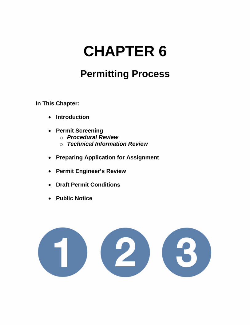
CHAPTER 6
Permitting Process
In This Chapter:
• Introduction • Permit Screening
o Procedural Review o Technical Information Review
• Preparing Application for Assignment
• Permit Engineer’s Review
• Draft Permit Conditions
• Public Notice

Michigan’s Permit to Install Workbook
Permitting Process 6-1
CHAPTER 6: Permitting Process Introduction The permitting process includes opportunities for face-to-face meetings between the Applicant and Permit Section Staff. Requirements and deadlines are clearly communicated at the start and throughout the permitting process. Further, any applicant may request a pre-application meeting with Permit Section staff. Submittal of a complete application is imperative to ensure that the application review process moves rapidly. A discussion of how to submit a complete application is found in Chapters 6 and 7.
Permit Screening The Permit Section of the AQD receives all Permit to Install applications. Each application is date stamped and then screened to ensure that the application form has been filled out correctly and that it contains all of the information for the Permit Engineer to begin the technical review (administratively complete). The Screener uses a checklist to ensure that the application is administratively complete. This screening checklist is divided into two sections: procedural review and technical information review. By understanding the AQD’s permit screening procedure, a permit Applicant can avoid costly and frustrating delays in getting a permit approved. Procedural Review: In the procedural review section, the Screener checks for a completed application form. Specifically, the screener ensures that:
• The application has the Applicant’s name and address and the location of the equipment • The process or equipment is described in the application • The application is signed by the facility owner or operator • The Applicant provided three copies of the application form and two copies of the
attachments. At least one copy of the application form must have an original signature. • The application clearly states whether it is for existing or new equipment • An authorized agent is identified
If any of this information is missing or unclear, the Screener returns the entire application to the Applicant with a letter explaining what information is needed for the application to be administratively complete. For applications that satisfy these requirements, the screener progresses to the technical information review portion of the checklist. Technical Information Review: In the technical information review section, the Screener determines if the application contains the technical information that is requested on the back of the application form. Specifically, the screener ensures that:
• Basic emission calculations and emission rates are provided • The operating schedule is described • Emission rates of toxic air contaminants and predicted ambient impacts are described
Michigan’s Permit to Install Workbook
6-2 Permitting Process
• It is apparent from which equipment the emissions occur • The stacks are sufficiently described to associate them with equipment and emission rates • The following stack parameters are provided for each stack:
height above ground inside diameter volumetric flow rate (specified as acfm or scfm) exhaust gas temperature orientation (vertical or horizontal) description of rain protection, if applicable
• Adequate site description information is provided including building dimensions, distances to property line, and location of stacks or other emission points
If any information is missing from technical information part of the review, the application will not be accepted, but will proceed through the “Off-Line” Tracking process. The Screener will send a letter to the Applicant that identifies the application deficiencies and a date that a response is needed. If a response is not received within the specified timeframe, the application package will be returned to the Applicant. Applications for Exempt Processes: During the screening process, the Screener attempts to identify any applications for exempt processes. After confirming with the Permit Supervisor and AQD District Staff that the process is exempt, the Screener notes it on the screening checklist. The Screener returns the application to the Applicant with a letter that explains that a permit is not needed because the application is for an exempt process. This letter cites the exemption rule, outlines any recordkeeping requirements, and contains a copy of the exemption rule.
Preparing Application for Assignment Permit Number: The AQD assigns each permit application a unique number. The permit number consists of two number fields separated by a dash (NNN-XX). The first number represents the chronological number of receipt. The second number represents the year of receipt. A permit identified as 349-96 was the 349th permit application received during 1996. If the permit application is for a modification, the AQD may use the original permit number with a letter suffix. For example, the first modification of permit 349-96 would be 349-96A. Assigning the Permit: After the screening procedures are complete, the AQD assigns the permit to a Permit Engineer in the Permit Section. The AQD assigns the applications based on the type of emission unit and the engineer’s expertise. The Applicant is notified which Permit Engineer is working on the project.
Permit Engineer’s Review The Permit Engineer performs several activities before recommending the approval or the denial of the permit. Some of these activities include determining whether the application is technically complete, confirming air contaminant emissions and calculations, and determining if the source complies with all applicable rules and regulations.

Michigan’s Permit to Install Workbook
Permitting Process 6-3
Assigning a SRN: Early in the review, the Permit Engineer determines if the facility has a state registration number (SRN). The SRN is a number that the AQD uses to identify facilities. It has five digits: a letter followed by four numbers, e.g., B2345. If the facility has ever submitted a permit application, it should have a SRN. If the facility does not have a SRN, the AQD will assign one. Emission Determination: The Permit Engineer’s next task is to determine both the potential and actual emissions for the facility, including the maximum hourly, monthly, and annual emissions. The Permit Engineer reviews the calculations in the application using U.S. Environmental Protection Agency (U.S. EPA) documents, applications for similar processes, performance tests, and other methods. He or she compares information from suppliers to information in the U.S. EPA resources, such as the Compilation of Air Pollutant Emission Factors AP-42, Factor Information Retrieval (FIRE), and the Technology Transfer Network (TTN) bulletin board. The Permit Engineer compares performance test results to emission values from U.S. EPA resources to determine if the results are acceptable. Compliance Determination and Regulatory Review: Next, the Permit Engineer determines if the facility is in compliance with all rules and regulations. This review is not limited to the equipment in the permit application – it includes other operations at the facility. The Permit Engineer informs the AQD Enforcement Unit if the facility violated any rule or regulation, including Michigan Rule 201 for installing equipment without a permit. Federal Rules: A key responsibility of the Permit Engineer is to review the federal and state rules and regulations to determine all of the applicable requirements. For federal rules, the Permit Engineer evaluates emission levels to determine if the proposal is subject to major source review requirements for either Prevention of Significant Deterioration (PSD) or for nonattainment areas. The Permit Engineer also determines if the facility is subject to requirements of a federal New Source Performance Standard (NSPS) or a National Emission Standard for Hazardous Air Pollutants (NESHAP). State Rules: The Permit Engineer also determines the facility’s capability to comply with every applicable state rule. The first step is usually a toxics review under Michigan Rules 224-230 to ensure that the facility’s emissions will not exceed any applicable screening levels. The AQD Modeling Staff uses simulation models to determine a prediction of the off-site impact of the toxic air contaminant to ensure that the impact is below the applicable screening level. If the facility will emit a substance that does not have a screening level, the Permit Engineer works with the AQD Toxic Staff to ensure that the toxic impact is acceptable. In addition to the air toxic rules, the Permit Engineer determines the applicability of other state rules, such as particulate standards and VOC emission limits. Other Agencies: Although the AQD permitting process is independent of other agency permits, the Permit Engineer may contact other governmental agencies about compliance with their rules and regulations before

Michigan’s Permit to Install Workbook
6-4 Permitting Process
recommending that the permit application be approved or denied. This may involve other divisions within the Department of Environmental Quality.
Draft Permit Conditions The permitting process involves two separate and distinct sets of draft conditions – Preliminary Draft Conditions and Final Draft Conditions. The Preliminary Draft Conditions are optional and, if used, would be sent to the Applicant early in the review process after most of the information is received; while the Final Draft Conditions are sent to the Applicant after all of the additional supporting information is received. The purpose of providing the Preliminary Draft Conditions is to give the Applicant insight regarding the final permit. Preliminary Draft Conditions may include: equipment covered, number and type of emission limits, operational restrictions, recordkeeping and reporting, testing, exhaust stack requirements, applicable requirements, etc. This will allow the Applicant an opportunity early in the permit process to alert the Permit Engineer of potential problems and/or concerns related to the conditions. It also gives the Permit Engineer, the district, and the Applicant additional time to address the potential problems and/or concerns and to develop a solution satisfactory to all parties. As the Preliminary Draft Conditions may be developed prior to complete review and evaluation of the application, they may not be all inclusive. Numerical emission limit values, stack parameters, testing requirements, etc., may not be included or complete. The Preliminary Draft Conditions may be subject to substantial change after the application is more thoroughly reviewed, and/or comments are considered. The Final Draft Conditions are based upon the final completed evaluation of the application, input from the district, and any comments received regarding the Preliminary Draft Conditions. If the Applicant has substantial questions, comments, and/or concerns with the Final Draft Conditions, a “Look-See” meeting should be scheduled and held. If the outstanding issues are not resolved, the Applicant may withdraw the application, or the AQD will either issue the permit or begin the public noticing procedures. In many cases, only one set of draft conditions may be sent to the Applicant. This will occur when the Permit Engineer, District Staff, and Applicant agree that the Preliminary Draft Conditions should be considered Final Draft Conditions.
Public Notice Some permit applications must go through a 30-day public comment period and, if requested, a public hearing. These applications include:
• Applications to install a major stationary source subject to either PSD or nonattainment area requirements.
• Major modification applications subject to either PSD or nonattainment area requirements. • Facilities netting out of PSD or major source nonattainment area requirements • Synthetic minor permit applications whose emission limitations restrict the potential to emit
to 90 percent or more of the major source thresholds. • Applications with significant public interest. • Major sources of hazardous air pollutants.

Michigan’s Permit to Install Workbook
Permitting Process 6-5
The AQD gives public notice by identifying the proposed permit in a local newspaper. The public notice includes the date, time, and location for a public hearing if one is requested during the 30-day public notice period.

Michigan’s Permit to Install Workbook
6-6 Permitting Process
NOTES

CHAPTER 7
What a PTI Looks Like
In This Chapter:
• Introduction o Federal Enforceability
• Permit Condition Examples
o General Conditions o Special Conditions
• Permit Status on the Internet
• Approved Permit to Install


Michigan’s Permit to Install Workbook
What a PTI Looks Like 7-1
CHAPTER 7: What a PTI Looks Like Introduction An approved Permit to Install will contain two sets of conditions: General Conditions and Special Conditions. These conditions are the basis and terms of the permit. The General Conditions are the same for all permits issued and are not negotiable. The Special Conditions are site and source specific conditions used to ensure compliance with applicable state and federal rules. There is room to negotiate with the Permit Engineer on the Special Conditions, reflecting the company’s preference in demonstrating compliance. The company must comply with both the General and Special Conditions of the permit at all times. Below are the General Conditions, as they appear in every PTI, and the Special Conditions category headings with a description of the type of conditions that go under each. The General Conditions reiterate air quality rules and regulations. They cover such items as general compliance and notification requirements, protection of air quality, changes in process or ownership, and substitution of materials. There are hundreds of standard Special Conditions that can be modified to fit a specific source. Some examples are shown below. Federal Enforceability A facility can reduce its potential to emit through the special conditions of its permit. By restricting its potential to emit, a facility may avoid federal requirements like major source review and ROP requirements. However, to effectively reduce the potential to emit, the permit must be federally enforceable. To be federally enforceable, the permit must contain an emission limit and either a production limit or operational limit. The combination of these limits must be enforceable as a practical matter. Also, the permit may have to go through a public comment period and hearing. A production limit restricts the amount of product over a period of time. An operational limit restricts the way the process is operated, including hours of operation, amount of raw materials used, or control equipment. Permit Condition Examples General Conditions: 1. The process or process equipment covered by this permit shall not be reconstructed,
relocated, or modified, unless a Permit to Install authorizing such action is issued by the Department, except to the extent such action is exempt from the Permit to Install requirements by any applicable rule. (R 336.1201(1))
2. If the installation, construction, reconstruction, relocation, or modification of the equipment for
which this permit has been approved has not commenced within 18 months, or has been interrupted for 18 months, this permit shall become void unless otherwise authorized by the Department. Furthermore, the permittee or the designated authorized agent shall notify the Department via the Supervisor, Permit Section, Air Quality Division, Michigan Department of Environmental Quality, P.O. Box 30260, Lansing, Michigan 48909-7760, if it is decided not to pursue the installation, construction, reconstruction, relocation, or modification of the equipment allowed by this Permit to Install. (R 336.1201(4))

Michigan’s Permit to Install Workbook
7-2 What a PTI Looks Like
3. If this Permit to Install is issued for a process or process equipment located at a stationary source that is not subject to the Renewable Operating Permit program requirements pursuant to R 336.1210, operation of the process or process equipment is allowed by this permit if the equipment performs in accordance with the terms and conditions of this Permit to Install. (R 336.1201(6)(b))
4. The Department may, after notice and opportunity for a hearing, revoke this Permit to Install if
evidence indicates the process or process equipment is not performing in accordance with the terms and conditions of this permit or is violating the Department’s rules or the Clean Air Act. (R 336.1201(8), Section 5510 of Act 451, PA 1994)
5. The terms and conditions of this Permit to Install shall apply to any person or legal entity that
now or hereafter owns or operates the process or process equipment at the location authorized by this Permit to Install. If the new owner or operator submits a written request to the Department pursuant to R 336.1219 and the Department approves the request, this permit will be amended to reflect the change of ownership or operational control. The request must include all of the information required by subrules (1)(a), (b), and (c) of R 336.1219 and shall be sent to the District Supervisor, Air Quality Division, Michigan Department of Environmental Quality. (R 336.1219)
6. Operation of this equipment shall not result in the emission of an air contaminant which
causes injurious effects to human health or safety, animal life, plant life of significant economic value, or property, or which causes unreasonable interference with the comfortable enjoyment of life and property. (R 336.1901)
7. The permittee shall provide notice of an abnormal condition, start-up, shutdown, or
malfunction that results in emissions of a hazardous or toxic air pollutant which continue for more than one hour in excess of any applicable standard or limitation, or emissions of any air contaminant continuing for more than two hours in excess of an applicable standard or limitation, as required in Rule 912, to the Department. The notice shall be provided not later than two business days after start-up, shutdown, or discovery of the abnormal condition or malfunction. Written reports, if required, must be filed with the Department within 10 days after the start-up or shutdown occurred, within 10 days after the abnormal conditions or malfunction has been corrected, or within 30 days of discovery of the abnormal condition or malfunction, whichever is first. The written reports shall include all of the information required in Rule 912(5). (R 336.1912)
8. Approval of this permit does not exempt the permittee from complying with any future
applicable requirements which may be promulgated under Part 55 of 1994 PA 451, as amended or the Federal Clean Air Act.
9. Approval of this permit does not obviate the necessity of obtaining such permits or approvals
from other units of government as required by law. 10. Operation of this equipment may be subject to other requirements of Part 55 of 1994 PA 451,
as amended and the rules promulgated thereunder. 11. Except as provided in subrules (2) and (3) or unless the special conditions of the Permit to
Install include an alternate opacity limit established pursuant to subrule (4) of R 336.1301, the permittee shall not cause or permit to be discharged into the outer air from a process or process equipment a visible emission of density greater than the most stringent of the

Michigan’s Permit to Install Workbook
What a PTI Looks Like 7-3
following. The grading of visible emissions shall be determined in accordance with R 336.1303. (R 336.1301)
a) A six-minute average of 20 percent opacity, except for one six-minute average per hour of not more than 27 percent opacity.
b) A visible emission limit specified by an applicable federal new source performance standard.
c) A visible emission limit specified as a condition of this Permit to Install. 12. Collected air contaminants shall be removed as necessary to maintain the equipment at the
required operating efficiency. The collection and disposal of air contaminants shall be performed in a manner so as to minimize the introduction of contaminants to the outer air. Transport of collected air contaminants in Priority I and II areas requires the use of material handling methods specified in R 336.1370(2). (R 336.1370)
13. The Department may require the permittee to conduct acceptable performance tests, at the
permittee’s expense, in accordance with R 336.2001 and R 336.2003, under any of the conditions listed in R 336.2001. (R 336.2001)
Special Conditions:
Emission Unit Identification
Emission Unit ID Emission Unit Description Stack Identification EUEDIPLINE1 E-Dip coating process for automotive parts.
Consists of 2 phosphate cleaning stations, a conveyor single E-dip station, bake oven, and natural gas-fired process boiler.
SV1 SV2
EUCHROME1 Decorative chrome plating line for automotive parts. Consists of an alkaline cleaning tank, acid dip tank, zinc plating tank, semi-bright dip tanks, bright dip tanks, and chromium tank.
SV3
EUGENERATOR1 Diesel fuel fired generator. SV4 EUGENERATOR2 Diesel fuel fired generator. SV5 Changes to the equipment described in this table are subject to the requirements of R336.1201, except as allowed by R336.1278 to R336.1290.
Flexible Group Identification
Flexible Group ID Emission Units Included in Flexible Group Stack Identification FGGENERATORS EUGENERATOR1
EUGENERATOR2 SV4 SV5
FGFACILITY All process equipment at the facility including equipment covered by other permits, grand-fathered equipment and exempt equipment.
The following conditions apply to: EUEDIPLINE1
Description: E-Dip coating process for automotive parts Flexible Group ID: n/a

Michigan’s Permit to Install Workbook
7-4 What a PTI Looks Like
Pollution Control Equipment: none Emission Limits
Pollutant Equipment Limit Time Period Testing/
Monitoring Method
Applicable Requirement
1.1 VOC EUEDIPLINE1 10 tpy 12-month rolling time period as determined at the end of each calendar month
R336.1702(a)
Special Conditions limiting the emission of specific pollutants (benzene) or groups of pollutants (VOCs, HAPs)
Visible Emission Limits 1.2 Visible emissions from EUEDIPLINE1 shall not exceed a six-minute average of 10 percent
opacity. [R336.1301, R336.1331] Special Conditions limiting the opacity from portions or all of the emission unit Material Usage Limits 1.3 The VOC content of all phosphate cleaning agents used in EUEDIPLINE1 shall not exceed
15 percent by weight. [R336.1225, R336.1901] Special Conditions limiting the material throughput or material make-up Process/Operational Limits 1.4 The heat input capacity of the EUEDIPLINE1 process boiler shall not exceed a maximum of
9.5 MM Btu per hour. [R336.1205] Special Conditions requiring certain parameters be met (temperature of incinerator, follow federal regulations, use only listed wells, hours of operation limitation, implement fugitive dust or malfunction abatement plan, etc.) Equipment 1.5 The permittee shall equip and maintain the EUEDIPLINE1 process boiler with a gas input
meter. [R336.1205, R336.1225, R336.1910] Special Conditions requiring certain equipment be installed and operating (oxidizers, gauges, HVLP applicators, continuously burning pilot flames, fencing, etc.) Testing 1.6 Within 180 days after commencement of trial operation, verification of VOC emission rates
from EUEDIPLINE1, by testing at owner’s expense, in accordance with Department requirements, will be required. No less than 30 days prior to testing, a complete test plan shall be submitted to the AQD. The final plan must be approved by the AQD prior to testing. Verification of emission rates includes the submittal of a complete report of the test results to the AQD within 60 days following the last date of the test. [R336.1205, R336.1702, R336.2001, R336.2003, R336.2004]
Special Conditions for performance testing after installation of emission unit to show compliance (emission rate, opacity, VOC/HAP content, control efficiency, etc.)

Michigan’s Permit to Install Workbook
What a PTI Looks Like 7-5
Monitoring 1.7 The permittee shall monitor, in a satisfactory manner, the natural gas input to the
EUEDIPLINE1 process boiler on a continuous basis. [R336.1205, R336.1225, R336.1910] Special Conditions requiring specific parametric monitoring Recordkeeping/Reporting/Notification 1.8 The permittee shall keep, in a satisfactory manner, daily natural gas consumption records for
the EUEDIPLINE1 process boiler, as required by SC 1.7. All records shall be kept on file for a period of at least five years and made available to the Department upon request. [R336.1205, R336.1225, R336.1910]
Special Conditions requiring recordkeeping of specific parametric monitoring or submittal of reports and notifications Stack/Vent Restrictions
Stack & Vent ID Maximum Diameter (inches)
Minimum Height Above Ground Level
(feet) Applicable
Requirement
1.9a SV1 12 30 R336.1225 1.9b SV2 8 45 R336.1225 The exhaust gases shall be discharged unobstructed vertically upwards to the ambient air. Special Conditions requiring emissions be routed to atmosphere in specific ways Permit Dates 1.10 Within 30 days of issuance of this permit, the permittee shall label the process tanks
according to a method acceptable to the AQD District Supervisor. Within seven days of completing the labeling, the permittee shall notify the AQD District Supervisor, in writing, as to the date the labeling was completed. [R336.1201]
Special Conditions giving specific time lines to when a permit is effective, a permit is terminated, or compliance with conditions must be achieved Portable Equipment 1.11 The permittee shall not operate EU at this site for more than two (2) years beyond the
issuance date of this permit. The permittee shall keep a record of the number of years EU operates at this site. This information shall be kept on file for a period of at least five years and made available to the Department upon request. [R336.1201]
Special Conditions to help ensure portable equipment is operated in compliance with rules Permit Status on Internet A Permit Applicant can look up the status of its pending application at www.deq.state.mi.us/aps/PendApps.asp (see Figure 7-1). By using this Internet query, the applicant can find out which Permit Engineer is assigned to its permit application and when the application was received, assigned, and completed.

Michigan’s Permit to Install Workbook
7-6 What a PTI Looks Like
Approved Permit to Install After the AQD has decided to issue a permit, it will send the following items to the applicant:
• A cover letter confirming that the permit was approved;
• A copy of the permit application that has been signed and stamped as approved;
• A permit certificate that has been signed and
stamped as approved; and
• Attachments that consist of the General and Special Conditions and any appendices to the conditions.
Figure 7-1: Permit Section Pending Application Query

Michigan’s Permit to Install Workbook
What a PTI Looks Like 7-7
STATE OF MICHIGAN
DEPARTMENT OF ENVIRONMENTAL QUALITY LANSING
RICK SNYDER GOVERNOR
Keith Creagh DIRECTOR
January 15, 2016
Mr. Tex Mills Chromewell Plating, Inc. 15000 W. Main Street Holland, Michigan 49484 Dear Mr. Mills: This letter is in reference to your Permit to Install application for a new chrome plating process (State Registration Number B7856) located at 15000 W. Main St., Holland, Michigan. This application, identified as No. 1234-15, has been evaluated and approved by the Air Quality Division, pursuant to the delegation of authority from the Michigan Department of Environmental Quality. This approval is based upon and subject to compliance with all administrative rules of the Department and conditions stipulated in the attached supplement. Please review these conditions thoroughly so that you may take the actions necessary to ensure compliance with all of these conditions. Please contact me if you have any questions regarding this permit.
Sincerely, Permit Engineer Permit Section Air Quality Division (Telephone number)
Attachment cc:Grand Rapids District Supervisor

Michigan’s Permit to Install Workbook
7-8 What a PTI Looks Like
MICHIGAN DEPARTMENT OF ENVIRONMENTAL QUALITY AIR QUALITY DIVISION
November 14, 2015
NEW SOURCE REVIEW PERMIT TO INSTALL Permit No. 1234-15
ISSUED TO Chromewell Plating, Inc.
LOCATED AT 15000 W. Main Street
Holland, Michigan 49484
IN THE COUNTY OF Ottawa
STATE REGISTRATION NUMBER B7856
The Air Quality Division has approved this Permit to Install, pursuant to the delegation of authority from the Michigan Department of Environmental Quality. This permit is hereby issued in accordance with and subject to Part 5505(1) of Article II, Chapter I, Part 55 (Air Pollution Control) of P.A. 451 of 1994. Pursuant to Air Pollution Control Rule 336.1201(1), this permit constitutes the permittee’s authority to install the identified emission unit(s) in accordance with all administrative rules of the Department and the attached conditions. Operation of the emission unit(s) identified in this Permit to Install is allowed pursuant to Rule 336.1201(6).
DATE OF RECEIPT OF ALL INFORMATION REQUIRED BY RULE 203:
February 13, 2005
DATE PERMIT TO INSTALL APPROVED: March 14, 2005
SIGNATURE:
DATE PERMIT VOIDED:
SIGNATURE:
DATE PERMIT REVOKED:
SIGNATURE:
CHAPTER 8
How to Comply With Your Permit to Install
In This Chapter:
• What Companies Should Know
o Reviewing the Draft Permit o Negotiating Draft Permit Special Conditions
• Compliance With the Permit to Install
o General Conditions o Special Conditions
• Compliance Monitoring
o Stack Testing o Continuous Emission Monitoring Systems (CEMS)
• Modifications to the Permit to Install


Michigan’s Permit to Install Workbook
How to Comply with Your Permit to Install 8-1
CHAPTER 8: How to Comply With Your Permit to Install A facility’s obligations to the Michigan Department of Environmental Quality, Air Quality Division (AQD) do not end after a Permit to Install is obtained. Once a facility receives a Permit to Install, it must continuously comply with the conditions of the permit. Additionally, a facility may have to obtain new permits in the future. The first step to complying with a permit is reading and understanding the conditions. The next step is to perform compliance monitoring to ensure that the facility is complying with its permit. The AQD monitors compliance by inspecting facilities, responding to complaints, reviewing facility tests and records, and following up on violations. What Companies Should Know The AQD will forward a draft Permit to Install to a company for its review and acceptance before the Permit to Install is issued. The draft permit contains terms and conditions that allow a company to operate in compliance with both state and federal rules and regulations. These terms and conditions are legally binding and are readily enforceable. Companies who eagerly accept permit conditions without first reviewing them usually find themselves operating in violation of their Permits to Install. Violations can prove to be costly. Therefore, it is essential that companies verify that they can comply with all of the terms and conditions prior to acceptance, and also seek revisions to their existing permits when they become aware that future production activities may put their facilities out of compliance. Reviewing the Draft Permit When reviewing the draft permit, there are several things the company should examine before accepting the conditions:
• Is description of permitted equipment accurate, including control equipment? • Are emission limits as expected? • Are material limit as expected? • Are the operation restrictions something the equipment is capable of? • Are the design parameters reflective of what will be installed? • If a specific test is listed, is it what was expected? • Is the timing of the required test feasible? • If monitoring equipment is required, is your equipment capable of operating with it? • Does the monitoring equipment measure the parameter listed? • Are the recordkeeping time periods and calculation methods possible? • Are the reporting requirements accurate? • Are the stack parameters accurate?
When your inspector comes out, these are the things they will be looking for. If errors are found in these items, the company could end up violating the permit by operating differently than what is required by the permit. The conditions in the permit will govern how the company is allowed to operate and by what parameter they are able to do so. Review of the draft conditions are best addressed by a company’s own plant personnel, even if a consultant has been hired to obtain the permit. Companies should have their production and plant managers review the draft permit to determine if the permit allows production and other activities to operate at capacity without severe restrictions. Plant personnel who purchase raw materials for production should also be involved with the review of the draft permit. They should be made aware of any restrictions on materials that can be used for production. Sometimes, companies are so
Michigan’s Permit to Install Workbook
8-2 How to Comply with Your Permit to Install
eager to start installation and production that they fail to inform key personnel who need to be aware of these limitations. While errors are a rare occurrence, it does occasionally happen. Therefore, be sure to review the draft permit for accuracy. Negotiating Draft Permit Special Conditions Many companies are not aware that they can negotiate terms and conditions contained in special conditions prior to acceptance of those conditions. Offer an alternative for those conditions that it may be difficult to comply with. The key to achieving a favorable outcome involves a well thought out alternative. Make sure your company understands all of the requirements and limitations before agreeing to the conditions. Every company should consider appointing a staff member as the environmental/permit coordinator for its facility. This individual should be responsible for overseeing environmental and permit issues at the plant and staying abreast of rule changes and how they can affect plant operations. Establishing an environmental coordinator can help a company ensure that production activities will remain in compliance. Compliance with the Permit to Install General Conditions: Maintaining compliance with the general conditions is straightforward. It requires a company to pursue immediate, future, or possible action to avoid violating a term or condition contained in a permit. Many of the general conditions involve notifications with an associated time frame. Companies need to make sure that they adhere to time frames, either with a response or completion of the required activity contained in the condition. A simple approach is to use tickler files, folders, or calendars that outline the timetables for submitting timely notifications for each of the following examples: Items Requiring Immediate Action:
• Applying for a new Permit to Install for the modification, reconstruction or relocation of any emission unit covered under an existing permit, except for those activities that are exempt by an applicable rule.
• Written notifications must be submitted within the time frames established in the condition. The notification must include all requirement information to be considered complete.
Items Requiring Future Action:
• Notification of the completion of the installation, reconstruction or relocation within 18 months; otherwise the Permit to Install will be void.
• Notification of a change of ownership with statement of acceptance of all existing permits, written agreements, consent orders, or judgments, along with documentation of purchase by the new owners.
• Notification of compliance with future regulations that are promulgated after issuance of the Permit to Install.

Michigan’s Permit to Install Workbook
How to Comply with Your Permit to Install 8-3
Special Conditions: Permits to Install are generally organized around the emission limits. In order to be enforceable as a practical matter a permit will contain both an emission limit and a related production or operational requirement that allows compliance with the emission limit to be determined. Often a single emission limit will have an equipment requirement, a monitoring requirement, and a recordkeeping requirement that accompany it. Such a situation may arise when, in order to meet an emission limit, the installation and operation of a control device is required and a key operating parameter of the control device (e.g., pressure drop, temperature, liquid flow rate, etc.) must be continuously monitored and recorded. As mentioned earlier, there are different categories or types of special conditions. The following are brief tips toward complying with different types of special conditions: Emission and Visible Emission Limits: There are several approaches to ensure compliance with emission limits. Each will depend on the method used to determine the emission rate from the emission unit. If we consider a paint spray booth where the total coating usage rate was used to determine the short and long term emission limits, we may use recordkeeping as a method of compliance. By knowing the quantity of coating used over a known period of time, AQD Staff can determine compliance with an emission limit. Records should be made readily available on-site for AQD District Staff’s review upon request. Data from a continuous emission monitoring system (CEMS) or a continuous opacity monitoring system (COMS) are a proven method for demonstrating compliance. Once a CEMS or COMS is calibrated, it will provide nonstop information about an emitted pollutant or the opacity of emissions from an emission unit. Purchasing, installing and operating a CEMS or a COMS can be an expensive solution for demonstrating compliance and the system will require periodic checks to ensure proper functioning. However, it is one of the most accurate of the available alternatives. Evaluating compliance with visible emission limits sometimes requires periodically observing the emissions leaving the stack. Such an observation regimen may require a trained observer. In all cases, records of the results of the observations are required to be maintained. This method allows a lower-cost alternative to the installation of a COMS. However, it is not an available alternative in every case. Another method to demonstrate compliance with an emission limit is by maintaining records of work practices. There are some cases where properly operating the production equipment may limit the emission of a pollutant. Showing the company’s continued compliance with standards of practice can demonstrate proper use of an emission unit within required operating parameters. Process/Operational Parameters: Compliance with operational parameters begins with management. Plant production must limit the operation of emission units in a manner that complies with the terms in the special conditions. Assigning an individual to be the environmental/permit coordinator is recommended. This individual, as well as line supervisors, can:
Monitor material usage limitations. Track operating temperature. Track back pressure limitations for an emission unit, or control device. Post procedures for other personnel members.

Michigan’s Permit to Install Workbook
8-4 How to Comply with Your Permit to Install
These parameter requirements should be reinforced with all line operators on a periodic basis. Usually these types of conditions require recordkeeping to demonstrate compliance. Testing: All test protocols should be submitted to and reviewed by the Technical Programs Unit of AQD. They have copies of approved test protocols that can be tailored to meet the needs of your company. Both designing and performing stack tests require a great deal of knowledge. Therefore, we suggest that companies hire a firm to design and conduct the test. Special conditions for testing requirements usually establish a deadline by which results must be reported. Monitoring: All monitoring equipment and practices should be reviewed and approved by the AQD prior to adopting. Monitoring activities should be practical, easy for plant personnel to perform, and most importantly, should adequately demonstrate compliance. Existing forms or practices that a company has in place for plant personnel should be used for monitoring procedures whenever possible. If approved, the plan and procedure should be readily available to all plant staff. Monitoring procedures must allow others to reproduce similar data/results regardless of who is conducting the monitoring. Some monitoring procedures are considered as “established standards” and cannot be changed. These must be followed as they are written. Monitoring can be as simple as checking the back pressure on a device and being able to demonstrate compliance through recordkeeping; or as complex as using a CEMS with a computer database. Recordkeeping/Reporting/Notification: All recordkeeping methods must be in agreement with the requirements contained in the special condition and compliance with each requirement must be demonstrated. Each method should be discussed and reviewed by the AQD District Staff prior to incorporating the use of the method. This ensures that the proposed method is appropriate and designed in an acceptable format that allows the company to demonstrate compliance. All records must be easily accessible to AQD District Staff for review. File drawers dedicated to maintaining these records are recommended. Compliance Monitoring The purpose of compliance monitoring is to ensure that the facility is operating in compliance with its Permit to Install. There are several ways to perform compliance monitoring, including stack testing and monitoring. Stack Testing: A stack test is often the ultimate determination of compliance. The results of a stack test are of great significance to both the AQD and the facility. Therefore, it is important that the test be performed in a valid and representative manner. The complex nature of the various sampling methods places great responsibility on both the AQD and on testing personnel to ensure that each test accurately represents a facility’s actual emissions. Stack tests must be performed in accordance with federal or state test methods and procedures. At least 30 days before the scheduled test date (unless another time frame is required by permit condition), submit a test plan should be submitted to the AQD. This test plan should include the following information:

Michigan’s Permit to Install Workbook
How to Comply with Your Permit to Install 8-5
• Identification and a brief description of the source to be tested. The description should include: Names, addresses, and telephone numbers of the contact persons for information
regarding the source and the test plan
Type of industrial process or combustion facility
Type and quantity of raw and finished materials used in the process
Description of any cyclical or batch operations which would tend to produce variable emissions with time
Basic operating parameters used to regulate the process
Rated capacity of the process
A brief description of any air pollution control equipment associated with the process:
Type of control device
Operating parameters
Rated capacity and efficiency
The applicable permit number and emission limits for the process
Identification of all pollutants to be measured
A description of the sampling trains to be used
Detailed sampling and analytical procedures
The number and length of sampling runs that will constitute a complete test A dimensioned sketch showing all sampling ports in relation to breeching and to upstream
and downstream disturbances or obstructions of gas flow Estimated flue gas conditions such as temperature, moisture, and velocity Projected process operating conditions during which the tests will be run (e.g., production
rate) A description of any process or control equipment data to be collected during the test
period A description of any monitoring data to be collected during the test period and
subsequently reported Chain of custody procedures Field quality assurance/quality control procedures (e.g., field blanks, sample storage, and
transport methods) Laboratory quality assurance/quality control procedures (e.g., manner and frequency of
blanks, spikes, and standards) Names and titles of personnel who will be performing the tests
Two copies of the test report should be submitted to the AQD within 60 days after the stack test (or other time frame specified by permit condition). In addition to the test results, the report should include descriptions of the source, the sampling and analytical methodology used, the process operating conditions, and all field and lab data and calculation methods. The test report is a stand-alone document, and it may repeat information supplied in the permit application. However, the test report will serve as evidence to both the AQD and the facility of the compliance status of the facility. Therefore, completeness is important for both content and quality. Although the exact format of the report and the required information vary depending on the source and the pollutants, the following is an outline for a complete test report:
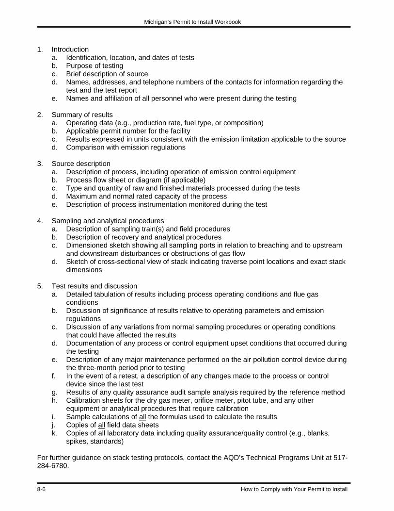
Michigan’s Permit to Install Workbook
8-6 How to Comply with Your Permit to Install
1. Introduction
a. Identification, location, and dates of tests b. Purpose of testing c. Brief description of source d. Names, addresses, and telephone numbers of the contacts for information regarding the
test and the test report e. Names and affiliation of all personnel who were present during the testing
2. Summary of results
a. Operating data (e.g., production rate, fuel type, or composition) b. Applicable permit number for the facility c. Results expressed in units consistent with the emission limitation applicable to the source d. Comparison with emission regulations
3. Source description
a. Description of process, including operation of emission control equipment b. Process flow sheet or diagram (if applicable) c. Type and quantity of raw and finished materials processed during the tests d. Maximum and normal rated capacity of the process e. Description of process instrumentation monitored during the test
4. Sampling and analytical procedures
a. Description of sampling train(s) and field procedures b. Description of recovery and analytical procedures c. Dimensioned sketch showing all sampling ports in relation to breaching and to upstream
and downstream disturbances or obstructions of gas flow d. Sketch of cross-sectional view of stack indicating traverse point locations and exact stack
dimensions 5. Test results and discussion
a. Detailed tabulation of results including process operating conditions and flue gas conditions
b. Discussion of significance of results relative to operating parameters and emission regulations
c. Discussion of any variations from normal sampling procedures or operating conditions that could have affected the results
d. Documentation of any process or control equipment upset conditions that occurred during the testing
e. Description of any major maintenance performed on the air pollution control device during the three-month period prior to testing
f. In the event of a retest, a description of any changes made to the process or control device since the last test
g. Results of any quality assurance audit sample analysis required by the reference method h. Calibration sheets for the dry gas meter, orifice meter, pitot tube, and any other
equipment or analytical procedures that require calibration i. Sample calculations of all the formulas used to calculate the results j. Copies of all field data sheets k. Copies of all laboratory data including quality assurance/quality control (e.g., blanks,
spikes, standards) For further guidance on stack testing protocols, contact the AQD’s Technical Programs Unit at 517-284-6780.

Michigan’s Permit to Install Workbook
How to Comply with Your Permit to Install 8-7
Continuous Emission Monitoring Systems: Continuous emission monitoring systems (CEMS) have monitoring equipment that accumulates data on a pre-determined time schedule in a stack or duct. Many of the principles of stack testing apply to CEMS. The difference is that a stack test records data only during the test (a few hours) while CEMS record data continuously. When using CEMS, you should adhere strictly to state and federal guidelines. Samples must be drawn, analyzed, and reported according to the procedures that are pre-approved by the AQD. Because of the precision and accuracy required for acceptable test results, the AQD recommends that experienced professionals implement CEMS. Before establishing a CEMS, the facility must submit a monitoring plan to the AQD. This will uncover potential problems with the CEMS involving locations of probes or monitors, types of monitors, what the data acquisition system is capable of producing, the monitor’s span and instrument range, and when the CEMS will be installed and tested. The following information should be included in a monitoring plan: A general description of the process and pollution control equipment
A flow diagram showing the sample acquisition points or paths in relation to the following: Flow disturbances (fans, elbows, inlets, outlets, etc.) Pollution control equipment Emission point of monitored gases to the atmosphere Flue walls at the sample acquisition location
System information Pollutants or parameters to be monitored Operating principles of the analyzers Number of analyzers, including number of sample acquisition points or paths per analyzer
and locations monitored by each Equipment manufacturer, model numbers, and serial numbers Type of probe Equipment specifications of monitors Formulas including any factors used to calculate emission in the units of the applicable
standard Span values of all pollutant monitors Instrument ranges of all pollutant monitors Proposed daily calibration gas, calibration error, linearity, and cylinder gas audit values Data acquisition system/data recorder resolution
The expected date of monitor installation and performance specification testing The AQD will witness the initial performance specification testing or annual relative accuracy test audits to prove that CEMS data is efficient. Testers should provide the AQD with a test protocol before testing occurs. The test protocol should provide the following information: • CEMS description • Reference method testing description • Seven-day calibration drift test • Relative accuracy test • Calculations • Source operating data

Michigan’s Permit to Install Workbook
8-8 How to Comply with Your Permit to Install
Facilities with CEMS must report quarterly to the AQD. There are two reporting elements: a summary report and an excess emission report (EER). A summary report conveys information on CEMS downtime and excess emissions. An EER tracks the events when monitored emissions exceed the emissions standards. These reports indicate whether or not the facility is using good operating and maintenance practices to minimize emissions. An EER should include the following information: • Total operating time of each source during the reporting period
• Documentation of excess emissions: Date of each exceedance of the applicable standard Start and end time of each exceedance of the applicable standard Magnitude of each exceedance of the applicable standard Nature or cause of each exceedance of the applicable standard and averaging period Corrective action or preventive measures of each exceedance of the applicable standard
• Any mathematical factors used to convert emissions to units of the applicable standard
• Documentation of monitoring system performance: Date when monitoring system was inoperative Start and end time when the monitoring system was inoperative Nature of system repairs or adjustments
• Documentation of any time the monitor exceeded the instrument range including the date, time, duration, nature or cause, and corrective action
• A statement that no exceedances or monitor system outage occurred, if this is the case
• A summary of excess emissions For further guidance on CEM protocols, contact the AQD’s Technical Programs Unit at 517-284-6780. Modifications to the Permit to Install In addition to complying with permit conditions, a facility must sometimes obtain a new permit to modify, reconstruct, or relocate an emission unit. Some changes that may require a new permit include substituting new raw materials, such as coatings or fuels; increasing the hours of operation over previously permitted levels; or increasing the capacity of the emission unit, such as adding additional spray guns to a coating booth. For more information on whether a facility needs a new permit review the “Permit to Install Determining Applicability Guidebook” available at www.michigan.gov/air (select “Permits to Install/New Source Review” then “Application Form, Instructions and Guidance Documents”).

CHAPTER 9 Miscellaneous Issues
In This Chapter:
• Confidentiality
• Construction Waivers
• Voiding a Permit to Install
• Change of Ownership
• Tax Exemptions
• Pollution Prevention Loan Programs
• Environmental Audits
• Clean Corporate Citizen Program
• Michigan Air Emissions Reporting System
Other Misc.


Michigan’s Permit to Install Workbook
Miscellaneous Issues 9-1
CHAPTER 9: Miscellaneous Issues Confidentiality The contents of a Permit to Install application and the Permit to Install are considered public information and can be obtained through a Freedom of Information Act (FOIA) request. However, a permit applicant can classify some of its information as “confidential,” which means that the public cannot gain access to it. Section 5516(3) of Public Act 451 of 1994 and the Air Quality Division’s (AQD) Operational Memorandum No. 10 provide guidelines for what information can be kept confidential and how that information will be handled. A company can only keep certain types of information confidential. This includes information that could jeopardize the competitive position of a company if it were disclosed, such as:
• Trade secrets. • Process information. • Production information. • Commercial and financial information.
Procedure for Confidential Information: When submitting a permit application that contains confidential information, follow these steps:
• Separate the confidential information from all of the other permit materials. • Stamp every confidential page “CONFIDENTIAL.” • Place the confidential information in an envelope that is stamped “CONFIDENTIAL.”
After receiving confidential information, AQD Staff will determine if the information can remain confidential. If the AQD determines that the information is not confidential, the applicant has 25 days to demonstrate confidentiality. Information that the AQD allows to be disclosed to the public cannot be held as confidential information. Things that should not be marked confidential include:
• An entire permit application. • Material safety data sheets (MSDS). • Emissions information (as it relates to quantity, composition, or quality of emissions or to
the amount and nature of air contaminants emitted ). • Air contaminants released into the environment. • Limits in a Permit to Install, consent order, or judgment.
The Air Quality Division’s (AQD) Operational Memorandum No. 10 can be accessed at www.michigan.gov/air (select “State Air Laws and Rules” then “AQD Policy and Procedures”). Freedom of Information Act (FOIA) Requests: The public can obtain any information from a permit application that is not confidential by submitting a FOIA request to the AQD. FOIA requests must be sent in writing and can be sent to the FOIA Coordinator by fax, e-mail, or postal mail. See the DEQ FOIA webpage at

Michigan’s Permit to Install Workbook
9-2 Miscellaneous Issues
www.michigan.gov/deq (scroll to the bottom of the page and choose FOIA”) for the address and fax number of the FOIA Coordinator. The AQD has five business days to grant, deny, or partially grant and partially deny a FOIA request. The AQD can charge a fee to cover duplication, mailing, and clerical labor costs associated with the request.
Construction Waivers Michigan Rule 201 requires a facility to obtain a Permit to Install before constructing a new source or installing a new emission unit. In some cases, facilities could suffer economic losses if they delay construction until a permit is issued. Proper planning can help avoid some of these situations. The AQD can address some of these timing conflicts by issuing construction waivers in certain cases. Michigan Rule 202 authorizes construction waivers, which allow a facility to begin construction before the Permit to Install is issued. A construction waiver will not allow the facility to begin operating the equipment, even on a trial basis, without first obtaining its permit. There are several requirements that a facility must satisfy to have a construction waiver request approved: 1. A Permit to Install application must be submitted before, or with, a construction waiver request. 2. The AQD will not grant construction waivers for sources that are subject to either of the two
federal New Source Review (NSR) programs that it administers. These are the major source review programs for attainment and nonattainment areas in Parts 18 and 19 of the Rules for Air Pollution Control, respectively. Additionally, major sources of HAPs regulated by a NESHAP cannot be granted a construction waiver. These three programs are federal requirements that cannot be waived by the MDEQ. See Chapter 4 for more information about these programs.
3. The AQD will not grant a construction waiver if there is any public controversy or zoning issue
for the proposed activity. An applicant must resolve these issues before obtaining a construction waiver.
4. The applicant assumes all risk and liability if a source is constructed and then a Permit to
Install is not approved. This risk includes lost revenue or additional construction costs to retrofit if additional requirements are later found to apply.
5. Applicants for a construction waiver must demonstrate an undue hardship such as the loss of
a competitive edge in a marketplace, a significant loss in contracts or bids, or a loss of an opportunity to pursue a business venture.
According to Rule 202, the request for a waiver shall be in writing. All construction waiver requests are reviewed and approved by the appropriate AQD District Office. See Chapter 1 for the addresses of the AQD District Offices. Although the Lansing AQD Staff review the air permit applications, the AQD District Staff review construction waiver requests. There is no cost for requesting a construction waiver. The AQD must take final action on the request within 30 days of receipt, unless additional information is required in order for the AQD to make its determination. Again, remember that the applicant assumes all risks associated with constructing before permit approval.

Michigan’s Permit to Install Workbook
Miscellaneous Issues 9-3
Voiding a Permit to Install There are several reasons to void a Permit to Install, including the following:
• The equipment has been removed or rendered inoperable. • The equipment no longer needs a Permit to Install because of an exemption. • The terms and conditions of the permit have been incorporated into a new Permit to Install,
either for a modification to the process or an opt-out permit. • The terms and conditions of the permit have been incorporated into a Renewable Operating
Permit. • The installation, reconstruction or relocation of the equipment did not commence within 18
months or was interrupted for 18 months, as specified in Michigan Rule 201(4). To request to void a Permit to Install, send a letter, fax, or e-mail to the AQD Permit Section (P.O. Box 30260, Lansing, Michigan 48909-7760) with a copy to the appropriate AQD District Supervisor. Include the following information in the request:
• The name of the company that holds the permit. • A description of the location or the street address of the equipment and the State
Registration Number (SRN). • The Permit to Install number. • A brief description of the process equipment covered by the request. • The reason for voiding the permit. If the reason for the request to void the Permit to Install
is an exemption, reference the specific exemption and include information showing the applicability of the exemption.
For more information, obtain a copy of the AQD’s Procedure for Voiding Permits to Install (revision date June 7, 1999) available at www.deq.state.mi.us/aps. Change of Ownership A facility must amend an existing Permit to Install when there is a change of ownership or operational control. To request a change of ownership, send a letter to the appropriate AQD District Supervisor (see Chapter 1, Figure 1-2) with a copy to the Permit Section at P.O. Box 30260, Lansing, MI 48909-7760. A change of ownership request should include all of the following information as required by Rule 219:
• A description of the facility or process. • A listing of the permits, voluntary agreements, consent orders, and judgments involved in
the request. • Identification of the new owner and a copy of the written agreement showing the specific
date of ownership transfer. • A written statement from the new owners accepting responsibility for the terms of the permit
and associated agreements or judgments. The AQD will respond in writing to the request within 60 days. The AQD’s Transfer of Ownership and Name Change Instructions are available at www.deq.state.mi.us/aps.
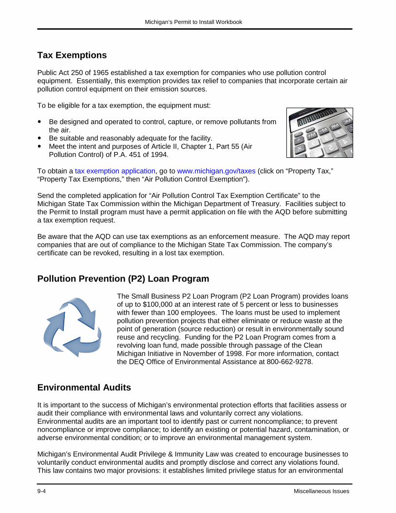
Michigan’s Permit to Install Workbook
9-4 Miscellaneous Issues
Tax Exemptions Public Act 250 of 1965 established a tax exemption for companies who use pollution control equipment. Essentially, this exemption provides tax relief to companies that incorporate certain air pollution control equipment on their emission sources. To be eligible for a tax exemption, the equipment must: Be designed and operated to control, capture, or remove pollutants from
the air. Be suitable and reasonably adequate for the facility. Meet the intent and purposes of Article II, Chapter 1, Part 55 (Air
Pollution Control) of P.A. 451 of 1994. To obtain a tax exemption application, go to www.michigan.gov/taxes (click on “Property Tax,” “Property Tax Exemptions,” then “Air Pollution Control Exemption”). Send the completed application for “Air Pollution Control Tax Exemption Certificate” to the Michigan State Tax Commission within the Michigan Department of Treasury. Facilities subject to the Permit to Install program must have a permit application on file with the AQD before submitting a tax exemption request. Be aware that the AQD can use tax exemptions as an enforcement measure. The AQD may report companies that are out of compliance to the Michigan State Tax Commission. The company’s certificate can be revoked, resulting in a lost tax exemption. Pollution Prevention (P2) Loan Program
The Small Business P2 Loan Program (P2 Loan Program) provides loans of up to $100,000 at an interest rate of 5 percent or less to businesses with fewer than 100 employees. The loans must be used to implement pollution prevention projects that either eliminate or reduce waste at the point of generation (source reduction) or result in environmentally sound reuse and recycling. Funding for the P2 Loan Program comes from a revolving loan fund, made possible through passage of the Clean Michigan Initiative in November of 1998. For more information, contact the DEQ Office of Environmental Assistance at 800-662-9278.
Environmental Audits It is important to the success of Michigan’s environmental protection efforts that facilities assess or audit their compliance with environmental laws and voluntarily correct any violations. Environmental audits are an important tool to identify past or current noncompliance; to prevent noncompliance or improve compliance; to identify an existing or potential hazard, contamination, or adverse environmental condition; or to improve an environmental management system. Michigan’s Environmental Audit Privilege & Immunity Law was created to encourage businesses to voluntarily conduct environmental audits and promptly disclose and correct any violations found. This law contains two major provisions: it establishes limited privilege status for an environmental

Michigan’s Permit to Install Workbook
Miscellaneous Issues 9-5
audit and it provides immunity from state fines and penalties for violations discovered through an environmental audit. The privilege provision allows certain information to be held confidential and not accessible to a state or local government agency or the public. Information that cannot be considered privileged includes: Information required to be available or reported to a regulatory agency or any other person as
required by law. Information obtained by observation, sampling, or monitoring by any regulatory agency. Pretreatment monitoring results that a publicly-owned treatment works or control authority
requires to be reported. Information from a person or source not associated with the environmental audit. Equipment maintenance records.
Once a facility discloses environmental audit information, it waives the privilege unless the information was disclosed under a confidentiality agreement. The confidentiality agreement sets out the type of information that will be held confidential and the conditions under which the Department of Environmental Quality (DEQ) will keep this information confidential. Under the immunity provision of this law, a person is immune from any administrative or civil fines and penalties and from criminal fines and penalties for negligent acts (other than acts of gross negligence) related to violations of the state’s environmental laws, if that person makes a voluntary disclosure of the violations to the appropriate agency. To be considered voluntary, the person making the disclosure must demonstrate that:
• The disclosure of the information arises out of an environmental audit. • The audit occurs before the person is made aware that he or she is under investigation by a
regulatory agency. • The disclosure is made promptly after knowledge of the environmental violation is obtained. • The person initiates an appropriate and good-faith effort to achieve compliance, pursues
compliance with due diligence, and promptly corrects the violation after its discovery.
This immunity does not eliminate or affect the legal responsibility to correct the violation, conduct necessary remediation, or pay damages. Moreover, this immunity only applies to Michigan’s environmental protection laws administered by the DEQ. There is no immunity from federal or local laws or regulations. To obtain an Environmental Audit Privilege & Immunity Law fact sheet and forms go to www.michigan.gov/deq (select “Environmental Incentives, Grants and Loans”). To encourage self-audits and voluntary disclosures, the Environmental Protection Agency (EPA) provides some relief from federal penalties for facilities that perform voluntary environmental audits. The federal policy on environmental audits and voluntary disclosure is explained in two documents:
• The May 11, 2000 EPA policy entitled “Incentives for Self-Policing: Discovery, Disclosure, Correction, and Prevention of Violations.”
• The May 11, 2000 “Policy on Compliance Incentives for Small Business.” The federal policy has immunity provisions, but no privilege. You can obtain a copy of these policies at www2.epa.gov/compliance/epas-audit-policy.

Michigan’s Permit to Install Workbook
9-6 Miscellaneous Issues
Clean Corporate Citizen (C3) Program The Clean Corporate Citizen Program (C3 Program) recognizes and rewards facilities that have consistently demonstrated a strong environmental ethic and stewardship. Facilities participating in the C3 Program can carry out their environmental protection responsibilities without rigorous oversight. Therefore, these facilities receive greater permitting flexibility than facilities that do not participate in the program. There are three criteria for participation in the C3 Program:
1. Develop an environmental management system that includes an identification of environmental impacts, self-initiated compliance audits, public participation, a clear statement of the facility’s commitment to environmental excellence, and environmental training for employees.
2. Implement pollution prevention strategies by making a commitment to reduce waste at the
source and by taking action to identify pollution prevention opportunities, establish goals to address these opportunities, report on accomplishments, and participate in information and technical exchange programs.
3. Demonstrate consistent compliance with all applicable environmental regulations and have
no outstanding, unresolved violations. There are several benefits for participating in the C3 Program. The air quality permitting benefits include: An expanded waiver provision, which allows clean corporate facilities to get a construction
waiver without showing hardship.
Expedited review of permit applications, which means that the AQD will issue or deny a permit within 30 days of receiving a complete application from a Clean Corporate Citizen facility (the AQD has additional time if a public hearing is required).
The availability of a plant-wide applicability limit, which means that a clean corporate citizen facility would not have to obtain permits for new processes as long as the emissions for the entire facility stayed below an emissions cap.
To become a Clean Corporate Citizen, a facility must first provide public notice of its C3 Program application and submit it for review. After public review, the facility submits the application to the DEQ for review. The DEQ will approve or deny the application. A Clean Corporate Citizen must renew its C3 designation annually. A facility can lose its C3 designation if the DEQ determines that the facility is not meeting the C3 Program criteria. For more information on the Clean Corporate Citizen Program, contact the Office of Environmental Assistance at 800-662-9278 or go to www.michigan.gov/deqc3.

Michigan’s Permit to Install Workbook
Miscellaneous Issues 9-7
Michigan Air Emissions Reporting System (MAERS) The federal Clean Air Act requires each state to maintain an inventory of air pollution emissions for certain facilities and update this inventory every year. Michigan’s emission inventory is the Michigan Air Emissions Reporting System (MAERS). The AQD maintains MAERS by having facilities report their emissions annually. Not every facility is required to report under MAERS. According to the AQD’s Operational Memorandum No. 13, facilities that are subject to NSPS or NESHAP or that use Rule 208a to opt-out of the ROP program must report emissions. In addition, facilities with actual emissions greater than the following thresholds must report their emissions annually:
CO 100 tons per year NOX 40 tons per year SO2 40 tons per year PM 25 tons per year PM-10 15 tons per year VOC 100 tons per year Pb 0.6 tons per year
MAERS reports are due by March 15 each year. In mid-January, the AQD notifies facilities that they must submit the MAERS report. For emissions from calendar year 2012, facilities will be notified in January 2013 that the emissions report is due by March 15, 2013. For more information about MAERS go to www.michigan.gov/air (select “Emissions”).

Michigan’s Permit to Install Workbook
9-8 Miscellaneous Issues
NOTES

APPENDIX A Hazardous Air Pollutant (HAP) List


CAS No. Chemical CAS No. Chemical CAS No. Chemical CAS No. Chemical 75070 Acetaldehyde 60355 Acetamide 75058 Acetonitrile 98862 Acetophenone 53963 2-Acetylaminofluorene 107028 Acrolein 79061 Acrylamide 79107 Acrylic acid 107131 Acrylonitrile 107051 Allyl chloride 92671 4-Aminobiphenyl 62533 Aniline 90040 o-Anisdine 1332214 Asbestos 71432 Benzene 92875 Benzidine 98077 Benzotrichloride 100447 Benzyl chloride 92524 Biphenyl 117817 Bis (2-ethylhexyl)
phthalate (DEHP) 542881 Bis (chloromethyl)
ether 75252 Bromoform 106990 1,3-Butadiene 156627 Calcium cyanamide 133062 Captan 63252 Carbaryl 75150 Carbon disulfide 56235 Carbon tetrachloride 463581 Carbonyl sulfide 120809 Catechol 133904 Chloramben 57749 Chlordane 7782505 Chlorine 79118 Chloroacetic acid 532274 2-Chloroacetophenone 108907 Chlorobenzene 510156 Chlorobenzilate 67663 Chloroform 107302 Chloromethyl methyl
ether 126998 Chloroprene 1319773 Cresols/Cresylic acid
(isomers and mixtures) 95487 o-Cresol 108394 m-Cresol 106445 p-Cresol 98828 Cumene 94757 2,4-D, salts and esters 3547044 DDE 334883 Diazomethane 132649 Dibenzofurans 96128 1,2-Dibromo-3-
chloropropane 84742 Dibutylphthalate 106467 1,4-Dichlorobenzene(p)
91941 3,3-Dichlorobenzidene 111444 Dichloroethyl ether
(Bis(2-chloroethyl)ether)
542756 1,3-Dichloropropene 62737 Dichlorvos 111422 Diethanolamine 21697 N,N-Diethyl aniline
(N,N-Dimethylaniline) 64675 Diethyl sulfate 119904 3,3- Dimethoxybenzidine 60117 Dimethyl
aminoazobenzene 119937 3,3-Dimethyl benzidine 79447 Dimethyl carbarmoyl
chloride 68122 Dimethyl formamide 57147 1,1 Dimethyl hydrazine 131113 Dimethyl phthalate 77781 Dimethyl sulfate 534521 4,6-Dintro-o-cresol, and
salts 51285 2,4-Dinitrophenol 121142 2,4-Dinitrotoluene 123911 1,4-Dioxane (1,4-
Diethyleneoxide) 122667 1,2-Diphenylhydrazine 106898 Epichlorohydin (1-
Chloro-2,3-epozypropane)
106887 1,2-Epozybutane 140885 Ethyl acrylate 100414 Ethyl benzene 51796 Ethyl carbamate
(Urethane) 75003 Ethyl chloride
(Chloroethane) 106934 Ethylene dibromide)
(Dibromoethane) 107062 Ethylene dichloride
(1,2-Dichloroethane) 107211 Ethylene glycol 151564 Ethylene imine
(Aziridine) 75218 Ethylene oxide 96457 Ethylene thiourea 75343 Ethylidene dichloride
(1,1-Dichloroethane) 50000 Formaldehyde 76448 Heptachlor 118741 Hexachlorobenzene 87683 Hexachlorobutadiene 77474 Hexachlorocyclo
pentadiene 67721 Hexachloroethane 822060 Hexamethylene-1,6-
diisocyanate 680319 Hexamethyl
phosphoramide 110543 Hexane
302012 Hydrazine 7647010 Hydrochloric acid 7664393 Hydrogen fluoride
(hydrofluoric acid) 123319 Hydroquinone 78591 Isophorone 58899 Lindane (all isomers) 108316 Maleic anhydride 67561 Methanol 72435 Methozychlor 74839 Methyl bromide
(Bromomethane) 74873 Methyl chloride
(Chloromethane) 71556 Methyl chloroform
(1,1,1-Trichloroethane) 60344 Methyl hydrazine 74884 Methyl iodide
(Iodomethane) 108101 Methyl isobutyl ketone
(Hexone) 624839 Methyl isocyanate 80626 Methyl methacrylate 1634044 Methyl tert butyl ether 101144 4,4-Methylene bis
(2-chloroaniline) 75092 Methylene chloride
(Dichloromethane) 101688 Methlene diphenyl
diisocyanate (MDI) 101779 4,4’-methylenedianiline 91203 Naphtalene 98953 Nitrobenzene 92933 4-Nitrobiphenyl 100027 4-Nitrophenol 79469 2-Nitropropane 684935 N-Nitroso-N-
methylurea 62759 N-
Nitrosodimethylamine 59892 N-Nitrosomorpholine 56382 Parathion 82688
87865 Pentachlorophenol 108952 Phenol 106503 p-Phenylenediamine 75445 Phosgene 7803512 Phosphine 7723140 Phosphorus 85449 Phthalic anhydride 1336363 Polycholrinated
biphenyls (Aroclors) 1120714 1,3-Propane sultone 57578 beta-Propiolactone 123386 Propionaldehyde 114261 Propoxur (Baygon) 75569 Propylene oxide
78875 Propylene dichloride (1,2-Dichloropropane)
75558 1,2-Propylenimine (2-Methyl aziridine)
91225 Quinoline 106514 Quinone 100425 Styrene 96093 Styrene oxide 1746016 2,3,7,8-
Tetrachlorodibenzo p-dioxin
79345 1,1,2,2-Tetrachloroethane
127184 Tetrachloroethylene (Perchloroethylene)
7550450 Titanium tetrachloride 108883 Toluene 95807 2,4-Toluene diamine 584849 2,4-Toluene
diisocyanate 95534 o-Toluidine 8001352 Toxaphene (chlorinated
camphene) 120821 1,2,4-Trichlorobenzene 79005 1,1,2-Trichloroethane 79016 Trichloroethylene 95954 2,4,5-Trichlorophenol 88062 2,4,6-Trichlorophenol 121448 Triethylamine 1582098 Trifluralin 540841 2,2,4-Trimethylpentane 108054 Vinyl acetate 593602 Vinyl bromide 75014 Vinyl chloride 75354 Vinylidene chloride
(1,1 Dichloroethylene) 1330207 Xylenes (isomers and
mixtures) 95476 o-Xylenes 108383 m-Xylenes 106423 p-Xylenes COMPOUNDS
Antimony compounds Arsenic compounds (inorganic including arsine) Beryllium compounds Cadmium compounds Chromium compounds Cobalt compounds Coke oven emissions Cyanide compounds Fine mineral fibers Glycol ethers* Lead compounds Manganese compounds Mercury compounds Nickel compounds Polycyclic organic matter Radionuclides (including radon) Selenium compounds
*Note: Ethylene glycol mono-butyl ether (EGBE) was removed from the HAP list in December 2004. Methyl ethyl ketone (MEK, 2-Butanone) was removed from the HAP list in December 2005.

APPENDIX B List of Excluded Substances


LIST OF COMPOUNDS EXCLUDED FROM THE DEFINITION OF A TOXIC AIR CONTAMINANT
Acetylene Aluminum metal dust Aluminum oxide (nonfibrous forms) Ammonium sulfate Argon
Hydrogen Iron oxide Lead Liquefied petroleum gas (LPG) Methane
Calcium carbonate Calcium hydroxide Calcium oxide Calcium silicate Calcium sulfate
Neon Nitrogen Nitrogen Oxide Nuisance particulates Oxygen
Carbon dioxide Carbon monoxide Cellulose Coal dust Crystalline silica emissions from processes specified in Rule 120(f)(xv)
Ozone Perlite Portland cement Propane Silicon Starch
Emery Ethane Graphite (synthetic) Grain dust Helium
Sucrose Sulfur dioxide Vegetable oil mist Water vapor Zinc metal dust


APPENDIX C Michigan Air Toxics Rules

Go to www.michigan.gov/air (select “News and Info” then “State Air Laws and Rules” then “Part 2”) R 336.1224 T-BACT requirement for new and modified source of air toxics; exemptions. (11/10/98) Rule 224. (1) A person who is responsible for any proposed new or modified emission unit or units for which an application for a permit to install is required by part 2 of these rules and which emits a toxic air contaminant shall not cause or allow the emission of the toxic air contaminant from the proposed new or modified emission unit or units in excess of the maximum allowable emission rate based on the application of best available control technology for toxics (T-BACT), except as provided in subrule (2) of this rule.
(2) The requirement for T-BACT in subrule (1) of this rule shall not apply to any of the following:
(a) An emission unit or units for which standards have been promulgated under section 112(d) of the clean air act or for which a control technology determination has been made under section 112(g) or 112(j) of the clean air act for any of the following:
(i) The hazardous pollutants listed in section 112(b) of the clean air act.
(ii) Other toxic air contaminants that are volatile organic compounds, if the standard promulgated under section 112(d) of the clean air act or the determination made under section 112(g) or 112(j) of the clean air act controls similar compounds that are also volatile organic compounds.
(iii) Other toxic air contaminants that are particulate matter, if the standard promulgated under section 112(d) of the clean air act or the determination made under section 112(g) or 112(j) of the clean air act controls similar compounds that are also particulate matter.
(b) An emission unit or units that is in compliance with all of the following:
(i) The maximum allowable emissions of each toxic air contaminant from the proposed new or modified emission unit or units is 0.1 pound per hour or less for a carcinogen or 1.0 pound per hour or less for any other toxic air contaminant.
(ii) The applicable initial threshold screening level for the toxic air contaminant is more than 200 micrograms per cubic meter.
(iii) The applicable initial risk screening level is more than 0.1 micrograms per cubic meter.
(c) An emission unit or units which only emits toxic air contaminants that are particulates or VOCs and which is in compliance with BACT or LAER requirements for particulates and VOCs.
R 336.1225 Health-based screening level requirement for new or modified sources of air toxics. (11/10/98)
Rule 225. (1) A person who is responsible for any proposed new or modified emission unit or units for which an application for a permit to install is required by part 2 of these rules and which emits a toxic air contaminant (TAC) shall not cause or allow the emission of the toxic air contaminant from the proposed new or modified emission unit or units in excess of the maximum allowable emission rate which results in a predicted maximum ambient impact that is more than the initial threshold screening

level or the initial risk screening level, or both, except as provided in subrules (2) and (3) of this rule and in R 336.1226.
(2) As an alternative to complying with the initial risk screening level in subrule (1) of this rule, a person may instead demonstrate compliance with the secondary risk screening level. For the purpose of complying with the secondary risk screening level, the total allowable emissions of the carcinogen from the proposed new or modified emission unit or units and all existing emission units at the stationary source shall not result in a maximum ambient impact that is more than the secondary risk screening level.
(3) If the ambient impacts of a carcinogen occur on industrial property or public roadways, as an alternative to complying with the initial risk screening level or secondary risk screening level in subrule (1) or (2) of this rule, a person may instead demonstrate compliance with either of the following provisions:
(a) The maximum allowable emission rate of the carcinogen from the proposed new or modified emission unit or units results in ambient impacts that meet both of the following requirements:
(i) The maximum ambient impact on industrial property or public roadways is less than or equal to the initial risk screening level multiplied by a factor of 10.
(ii) The maximum ambient impact on all property that is not industrial or a public roadway is less than or equal to the initial risk screening level.
(b) The total allowable emissions of the carcinogen from the proposed new or modified emission unit or units and all existing emission units at the stationary source result in ambient impacts that meet both of the following requirements:
(i) The maximum ambient impact on industrial property or public roadways is less than or equal to the secondary risk screening level multiplied by a factor of 10.
(ii) The maximum ambient impact on all property that is not industrial or a public roadway is less than or equal to the secondary risk screening level.
(4) Any owner or operator who utilizes the alternative criteria provided in subrule (3) of this rule shall notify the department if a change in land use occurs for property determined to be industrial or a public roadway. The notification shall be submitted to the department within 30 days of the actual land use change. Within 60 days of the land use change, the owner or operator shall submit to the department a plan for complying with the requirements of subrule (1) of this rule. The plan shall require compliance with subrule (1) of this rule not later than 1 year after the due date of the plan submittal.
(5) For the purposes of this rule, industrial property includes only property where the activities are industrial in nature, for example, manufacturing, utilities, industrial research and development, or petroleum bulk storage. The term industrial property does not include farms or commercial establishments.
(6) For the purpose of subrules (1), (2), and (3) of this rule, both of the following provisions apply:
(a) All polychlorinated dibenzodioxins and dibenzofurans shall be considered as 1 toxic air contaminant, expressed as an equivalent concentration of 2,3,7,8-tetrachlorodibenzo-p-dioxin, based upon the relative potency of the isomers emitted from the emission unit or units.
(b) If 2 or more toxic air contaminants are present and known to result in toxicological interaction, then the interactive effects shall be considered in establishing initial threshold screening levels, initial risk screening levels, and secondary risk screening levels.

R 336.1226 Exemptions from the health-based screening level requirement. (11/10/98) Rule 226. The health-based screening level requirement provided in R 336.1225(1) shall not apply to any of the following:
(a) Emissions of a toxic air contaminant that meet both of the following requirements:
(i) The emission rate is less than 10 pounds per month and 0.14 pound per hour.
(ii) The toxic air contaminant is not a carcinogen or a high concern toxic air contaminant listed in table 20.

Table 20. List of High Concern Toxic Air Contaminants Chemical Name CAS Number
2,4,6-trinitrotoluene (TNT) 118-96-7 2-diethylaminoethanol 100-37-8 Acrolein 107-02-8 allyl chloride 107-05-1 alpha chloroacetophenone 532-27-4 alpha-amylase 9000-90-2 antimony compounds1 Arsine 7784-42-1 barium compounds1 Biphenyl 92-52-4 Bromine 7726-95-6 chlorine dioxide 10049-04-4 chlormadinone acetate 302-22-7 Chlorpyrifos 2921-88-2 cobalt compounds1 Colophony 8050-09-7 Dibromochloropropane 96-12-8 dibutyltin oxide 818-08-6 Dichlorvos 62-73-7 diisocyanate compounds1,2 dimethyl sulfate 77-78-1 Glutaraldehyde 111-30-8 halogenated dimethylhydantoin compounds3 isocyanate compounds1,4 maleic anhydride 108-31-6 manganese compounds1 melengesterol acetate 2919-66-6 mercury compounds1 Octachlorostyrene 29082-74-7 osmium tetroxide 20816-12-0 Pentachlorobenzene 608-93-5 platinum soluble salt 7440-06-4 selenium compounds1 subtilisins (proteolytic enzymes)5 sulfuric acid (including sulfur trioxide and oleum) 7664-93-9 tetrachlorobenzene compounds6 thallium compounds1 vanadium pentaoxide 1314-62-1
1 These listings include any unique chemical substance that contains the named chemical (for example, antimony, barium, cobalt, diisocyanate, isocyanate, manganese, mercury, selenium, and thallium) as part of the chemical structure. 2 Diisocyanate compounds include compounds with 2 of the isocyanate functional groups (-CNCO). 3 Halogenated dimethylhydantoin compounds includes those compounds with a hydantoin infrastructure (NHCONHCOCH2) substituted by 2 methyl groups at the 5 position on the ringed structure and halogens at the 1 or 3 position or the 1 and 3 position. 4 Isocyanate compounds includes compounds with 1 or more of the isocyanate functional groups (-CNCO).
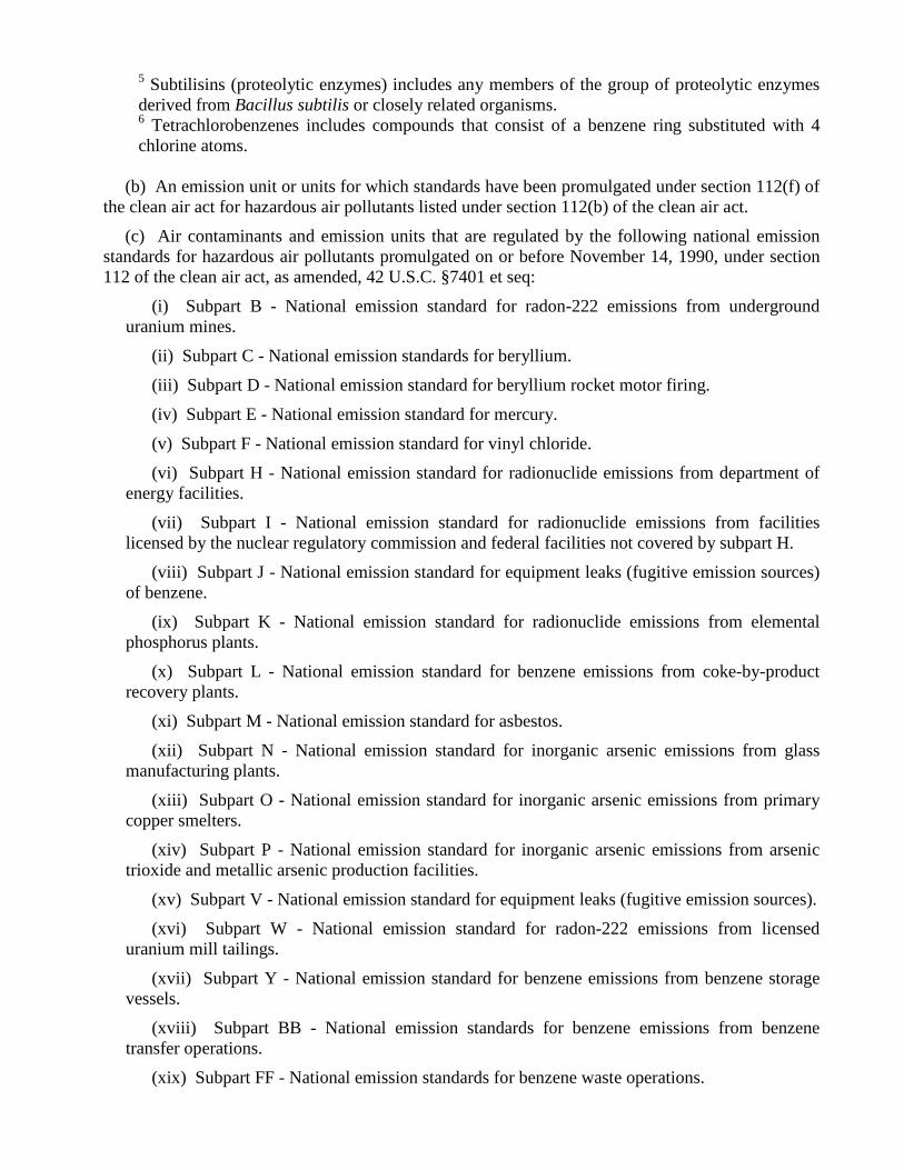
5 Subtilisins (proteolytic enzymes) includes any members of the group of proteolytic enzymes derived from Bacillus subtilis or closely related organisms. 6 Tetrachlorobenzenes includes compounds that consist of a benzene ring substituted with 4 chlorine atoms.
(b) An emission unit or units for which standards have been promulgated under section 112(f) of the clean air act for hazardous air pollutants listed under section 112(b) of the clean air act.
(c) Air contaminants and emission units that are regulated by the following national emission standards for hazardous air pollutants promulgated on or before November 14, 1990, under section 112 of the clean air act, as amended, 42 U.S.C. §7401 et seq:
(i) Subpart B - National emission standard for radon-222 emissions from underground uranium mines.
(ii) Subpart C - National emission standards for beryllium.
(iii) Subpart D - National emission standard for beryllium rocket motor firing.
(iv) Subpart E - National emission standard for mercury.
(v) Subpart F - National emission standard for vinyl chloride.
(vi) Subpart H - National emission standard for radionuclide emissions from department of energy facilities.
(vii) Subpart I - National emission standard for radionuclide emissions from facilities licensed by the nuclear regulatory commission and federal facilities not covered by subpart H.
(viii) Subpart J - National emission standard for equipment leaks (fugitive emission sources) of benzene.
(ix) Subpart K - National emission standard for radionuclide emissions from elemental phosphorus plants.
(x) Subpart L - National emission standard for benzene emissions from coke-by-product recovery plants.
(xi) Subpart M - National emission standard for asbestos.
(xii) Subpart N - National emission standard for inorganic arsenic emissions from glass manufacturing plants.
(xiii) Subpart O - National emission standard for inorganic arsenic emissions from primary copper smelters.
(xiv) Subpart P - National emission standard for inorganic arsenic emissions from arsenic trioxide and metallic arsenic production facilities.
(xv) Subpart V - National emission standard for equipment leaks (fugitive emission sources).
(xvi) Subpart W - National emission standard for radon-222 emissions from licensed uranium mill tailings.
(xvii) Subpart Y - National emission standard for benzene emissions from benzene storage vessels.
(xviii) Subpart BB - National emission standards for benzene emissions from benzene transfer operations.
(xix) Subpart FF - National emission standards for benzene waste operations.

(d) Emissions of a toxic air contaminant if it is demonstrated, on a case-by-case basis, to the satisfaction of the department, that the proposed new or modified emission unit or units will not cause or contribute to a violation of the provisions of R 336.1901. The demonstration shall include all relevant scientific information such as the following:
(i) All available information on the health effects of the toxic air contaminant.
(ii) The levels at which adverse health or environmental effects have occurred.
(iii) Net air quality benefits that would occur as a result of replacing an existing facility.
(iv) Actual exposure levels and duration of exposure.
(v) The uncertainty in data or analysis.
(vi) Other supporting information requested by the department.
R 336.1227 Demonstration of compliance with health-based screening level. (11/10/98) Rule 227. (1) Compliance with the health-based screening level provisions of R 336.1225 shall be determined by any of the following:
(a) The emission rate of each toxic air contaminant is not greater than the rates determined from the algorithms in table 21. If table 21 provides 2 allowable emission rates for a screening level specific averaging time, then compliance with both emission rates is required.
Table 21. Algorithms for determining allowable emission rates (AER)
Screening Level (SL) Averaging Time
Monthly Emission Rate (pounds per month)1,2
24 Hour Emission Rate (pounds per 24 hours)1,3
8 Hour Emission Rate (pounds per 8 hours)1,4
1 Hour Maximum Emission Rate (pounds per hour)1,5
Annual SL X 40 = AER SL X 0.54 = AER
24 hours SL X 0.12 = AER
SL X 0.05 = AER
8 hours SL X 0.02 = AER
SL X 0.02 = AER
1 hour SL X 0.001 = AER
1 All screening levels (SL) are in units of mg/m3. 2 The constant value of 40 is in units of lbs month
g m/
/m 3 .
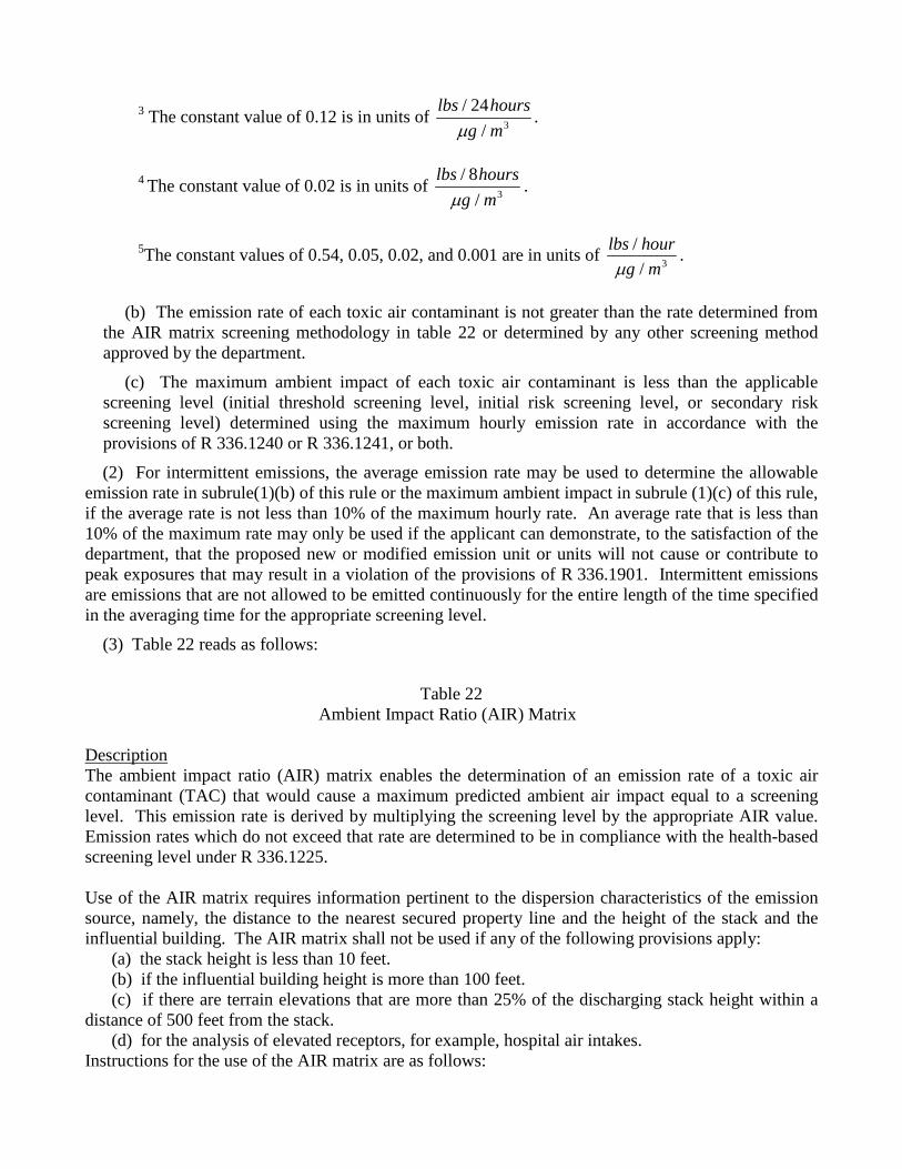
3 The constant value of 0.12 is in units of lbs hours
g m/
/24
3m.
4 The constant value of 0.02 is in units of lbs hours
g m/
/8
3m.
5The constant values of 0.54, 0.05, 0.02, and 0.001 are in units of lbs hour
g m//m 3 .
(b) The emission rate of each toxic air contaminant is not greater than the rate determined from the AIR matrix screening methodology in table 22 or determined by any other screening method approved by the department.
(c) The maximum ambient impact of each toxic air contaminant is less than the applicable screening level (initial threshold screening level, initial risk screening level, or secondary risk screening level) determined using the maximum hourly emission rate in accordance with the provisions of R 336.1240 or R 336.1241, or both.
(2) For intermittent emissions, the average emission rate may be used to determine the allowable emission rate in subrule(1)(b) of this rule or the maximum ambient impact in subrule (1)(c) of this rule, if the average rate is not less than 10% of the maximum hourly rate. An average rate that is less than 10% of the maximum rate may only be used if the applicant can demonstrate, to the satisfaction of the department, that the proposed new or modified emission unit or units will not cause or contribute to peak exposures that may result in a violation of the provisions of R 336.1901. Intermittent emissions are emissions that are not allowed to be emitted continuously for the entire length of the time specified in the averaging time for the appropriate screening level.
(3) Table 22 reads as follows:
Table 22
Ambient Impact Ratio (AIR) Matrix Description The ambient impact ratio (AIR) matrix enables the determination of an emission rate of a toxic air contaminant (TAC) that would cause a maximum predicted ambient air impact equal to a screening level. This emission rate is derived by multiplying the screening level by the appropriate AIR value. Emission rates which do not exceed that rate are determined to be in compliance with the health-based screening level under R 336.1225. Use of the AIR matrix requires information pertinent to the dispersion characteristics of the emission source, namely, the distance to the nearest secured property line and the height of the stack and the influential building. The AIR matrix shall not be used if any of the following provisions apply: (a) the stack height is less than 10 feet. (b) if the influential building height is more than 100 feet. (c) if there are terrain elevations that are more than 25% of the discharging stack height within a distance of 500 feet from the stack. (d) for the analysis of elevated receptors, for example, hospital air intakes. Instructions for the use of the AIR matrix are as follows:

Instructions 1. Determine the height of the discharging stack from ground level in feet (Hs). 2. Determine the height of the influential building in feet (Hb). This is done by first identifying all buildings, including buildings on-site and off-site, located within a distance of 5 times their height from the discharging stack. Then, determine which building is the highest. This is the influential building, with height (Hb) in feet. If the stack is not attached to a building, then a building height 2.5 times lower than the stack height must be assumed. 3. Determine the ratio of the stack height to the influential building height by dividing the stack height, in feet, by the influential building height, in feet, for example, Hs/Hb. 4. Determine the minimum distance, in feet, from the discharging stack to the secured property line. If there is no secured property line, then a distance of 25 feet is used. 5. Determine the appropriate value from the AIR matrix. This is done by selecting the column with the appropriate influential building height and Hs/Hb ratio, and selecting the row with the appropriate minimum distance to the secured property line. If the influential building height is between values in the column headings, then use the lower value or interpolate between values in the column headings. If Hs is less than Hb, then set the influential building height equal to the stack height and use the 1.25 Hs/Hb column. If Hs/Hb is between 1 and 1.25, then select the 1.25 column. If Hs/Hb is between 1.25 and 1.75, then use the 1.25 column or interpolate between the 1.25 and 1.75 columns. If Hs/Hb is between 1.75 and 2.5, then use the 1.75 column or interpolate between the 1.75 and 2.5 columns. If Hs/Hb is greater than or equal to 2.5, then use the 2.5 column. If the minimum distance to the secured property line is between 2 distances in the row headings, then use the lower value, for example, if the distance is 250 feet, then use the 200 foot distance row in the matrix. The value thus derived from the body of the matrix is the ratio of the annual averaged hourly emission rate divided by the maximum annual ambient impact, in units of (lbs/hr)/(ug/m3). This value is referred to as the annual AIR. 6. The annual averaged hourly emission rate ratio (annual AIR) is adjusted as necessary for shorter averaging times, consistent with the averaging times for the screening levels. This adjustment is done as follows:
24-hr AIR (lbs/hr)/(ug/m3) = annual AIR x 0.091. 8-hr AIR (lbs/hr)/(ug/m3) = annual AIR x 0.046. 1-hr AIR (lbs/hr)/(ug/m3) = annual AIR x 0.02.
7. Determine the maximum emission rate that would comply with the health-based screening level and averaging time. This is done by multiplying the screening level, in ug/m3, by the AIR value for the appropriate averaging time. The result is the highest emission rate, averaged over the averaging time period, that would be in compliance with the screening level. If a source’s maximum hourly emission rate does not exceed this, then the screening level would not be exceeded. If the emission is intermittent, then the emission rate can be averaged over the applicable averaging time as long as the averaged emission rate is not less than 10% of the maximum hourly emission rate, as specified in R 336.1227(2). 8. In the special case of TAC emissions from multiple stacks, determine the AIR value for each stack and select the lowest value among them. Then proceed as in step number 7.

Table 22. Ambient Impact Ratio (AIR) Matrix Annual Averaged Hourly Emission Rate Ambient Impact Ratios (AIRs) in Units of (lbs/hr)/(mg/m3)
for Toxic Air Contaminants (TACs) with Annual Averaged Screening Levels
BLDG HT (ft) 10 20 30 40 50 Hs / Hb 1.25 1.75 2.50 1.25 1.75 2.50 1.25 1.75 2.50 1.25 1.75 2.50 1.25 1.75 2.50 Stack Height-> 12.5 17.5 25.0 25.0 35.0 50.0 37.5 52.5 75.0 50.0 70.0 100.0 62.5 87.5 125.0
D 25 0.0085 0.022 0.159 0.032 0.084 0.679 0.075 0.220 1.603 0.152 0.421 2.941 0.263 0.736 4.630 I 50 0.0087 0.022 0.159 0.032 0.084 0.679 0.075 0.220 1.603 0.152 0.421 2.941 0.263 0.736 4.630 S 75 0.0096 0.022 0.159 0.032 0.084 0.679 0.075 0.220 1.603 0.152 0.421 2.941 0.263 0.736 4.630 T 100 0.011 0.023 0.159 0.033 0.084 0.679 0.075 0.220 1.603 0.152 0.421 2.941 0.263 0.736 4.630 A 200 0.020 0.040 0.159 0.042 0.084 0.679 0.082 0.220 1.603 0.157 0.421 2.941 0.266 0.736 4.630 N 300 0.030 0.053 0.178 0.059 0.113 0.679 0.099 0.221 1.603 0.174 0.421 2.941 0.282 0.736 4.630 C 400 0.040 0.065 0.171 0.077 0.140 0.679 0.126 0.268 1.603 0.200 0.421 2.941 0.312 0.736 4.630 E 500 0.051 0.077 0.189 0.094 0.164 0.679 0.153 0.318 1.603 0.243 0.505 2.941 0.351 0.743 4.630 600 0.063 0.091 0.222 0.112 0.188 0.746 0.181 0.368 1.603 0.287 0.588 2.941 0.409 0.838 4.630
F 700 0.075 0.104 0.241 0.130 0.211 0.812 0.208 0.413 1.603 0.328 0.664 2.941 0.468 0.951 4.717 T 800 0.089 0.119 0.257 0.148 0.235 0.768 0.235 0.459 1.608 0.370 0.740 2.941 0.528 1.064 4.803 900 0.103 0.134 0.264 0.167 0.258 0.770 0.261 0.502 1.672 0.411 0.812 2.941 0.585 1.168 4.854 1000 0.119 0.151 0.272 0.187 0.282 0.800 0.289 0.545 1.786 0.452 0.883 2.959 0.644 1.276 4.950 1500 0.209 0.245 0.318 0.290 0.406 1.080 0.428 0.756 1.953 0.654 1.214 3.521 0.924 1.761 5.376 2000 0.311 0.350 0.383 0.408 0.539 1.256 0.573 0.965 2.304 0.861 1.534 3.731 1.205 2.222 5.882 BLDG HT (ft) 60 70 80 90 100 Hs / Hb 1.25 1.75 2.50 1.25 1.75 2.50 1.25 1.75 2.50 1.25 1.75 2.50 1.25 1.75 2.50 Stack Height-> 75.0 105.0 150.0 87.5 122.5 175.0 100.0 140.0 200.0 112.5 157.5 225.0 125.0 175.0 250.0
D 25 0.412 1.114 6.098 0.606 1.656 8.621 0.839 2.242 8.333 1.126 3.049 13.514 1.458 3.876 14.286 I 50 0.412 1.114 6.098 0.606 1.656 8.621 0.839 2.242 8.333 1.126 3.049 13.514 1.458 3.876 14.286 S 75 0.412 1.114 6.098 0.606 1.656 8.621 0.839 2.242 8.333 1.126 3.049 13.514 1.458 3.876 14.286 T 100 0.412 1.114 6.098 0.606 1.656 8.621 0.839 2.242 8.333 1.126 3.049 13.514 1.458 3.876 14.286 A 200 0.413 1.114 6.098 0.606 1.656 8.621 0.839 2.242 8.333 1.126 3.049 13.514 1.458 3.876 14.286 N 300 0.426 1.114 6.098 0.614 1.656 8.621 0.845 2.242 8.333 1.129 3.049 13.514 1.458 3.876 14.286 C 400 0.455 1.114 6.098 0.641 1.656 8.621 0.868 2.242 8.333 1.147 3.049 13.514 1.475 3.876 14.286 E 500 0.498 1.114 6.098 0.683 1.656 8.621 0.909 2.242 8.333 1.185 3.049 13.514 1.506 3.876 14.286 600 0.545 1.114 6.098 0.741 1.656 8.621 0.967 2.242 8.333 1.244 3.049 13.514 1.563 3.876 14.286
F 700 0.625 1.269 6.250 0.808 1.672 8.621 1.040 2.242 8.333 1.316 3.049 13.514 1.634 3.876 14.286 T 800 0.705 1.429 6.410 0.901 1.825 8.621 1.111 2.242 8.333 1.404 3.049 13.514 1.730 3.876 14.286 900 0.781 1.572 6.579 1.000 2.016 8.621 1.235 2.488 9.091 1.502 3.086 13.514 1.832 3.876 14.286 1000 0.861 1.724 6.849 1.101 2.203 9.091 1.359 2.732 10.000 1.634 3.289 13.514 1.931 3.876 14.286 1500 1.232 2.404 7.042 1.577 3.106 9.615 1.953 3.846 11.905 2.358 4.505 15.152 2.778 5.208 16.129 2000 1.603 3.049 7.353 2.041 3.968 9.615 2.525 4.808 12.821 3.049 5.618 16.129 3.597 6.494 18.519


APPENDIX D Reference Table for Odors


Reference Table for Odors The MDEQ Air Quality Division (AQD) has conducted research into what data are available on odor threshold concentrations for various organic compounds. The attached table, originally from the Handbook of Environmental Data on Organic Chemicals by Verschueren, is the result. Some of the terms used in the table require some explanation: Threshold Odor Concentration There have been at least three different odor thresholds that have been used in various studies, At
the absolute perception threshold, one is barely certain that an odor is detected, but it is too faint to identify further. At the recognition threshold, the odor can be defined as being representative of the chemical being studied. Some studies have also attempted to identify an "objectionability threshold". The thresholds can also be defined by the degree of response of the odor panel conducting the study, 50% and 100% responses are commonly used. The threshold concentrations reported in this table are to be considered as the 50% Recognition Thresholds.
Odor Perception Concentration This is the concentration at which one is barely certain that an odor is detected. The literature
referenced was unclear as to whether the concentrations shown in this column are for the worst individual perception responses or 50% population (odor panel) perception responses. Both are probably used. In all cases, this number is the lowest reported positive odor response. Where an odor perception concentration has not been listed in the table, that indicated that only one odor threshold data point was available.
Odor Index This is an indicator of a compound's potential to cause an odor emission. It is a dimensionless term
based on vapor pressure and (in this reference) 100% Odor Recognition Concentration as:
Odor Index numbers greater than 1,000,000 are termed "high odor potential", 100,000 to 1,000,000 are "medium odor potential", and less than 100,000 are "Low odor potential". In many cases, a range of Threshold Odor Concentrations is given in this table. These ranges can vary up to 2 orders of magnitude. The variation between the Threshold and Perception Concentrations can range up to four orders of magnitude. The lack of a range of values for a given chemical most likely indicates a lack of odor data rather than good correlation between various studies. An air & Waste Management Association study into the accuracy of odor panel testing techniques has shown that a two order of magnitude variation in threshold concentrations is not uncommon. These data are provided for reference only and can reasonably be used as the basis for making engineering assumptions regarding an odor source. These data should not be considered as emission limits nor as an absolute indicator of the presence or absence of an odor nuisance.
Odor Index = VaporPressure (ppm)100% Odor Recognition Concentration (ppm)

THRESHOLD ODOR CONCENTRATION, ODOR PERCEPTION CONCENTRATION
AND ODOR INDEX FOR VARIOUS ORGANIC COMPOUNDS
Chemical Formula Odor Quality Threshold Odor Concentration
Odor Perception
Concentration Odor Index
BTX AROMATICS benzene C6H6 --- 3-65 ppm 1 ppm 300 toluene C6H5CH3 sour, burnt 2 ppm 0.2 ppm 720 xylenes C4H4(CH3)2 sweet 0.3-4 ppm 0.1 ppm 360-29,200 1,2,3,5-tetramethylbenzene
C4H2(CH3)4 --- 3 ppb --- 136,000
isopropylbenzene C4H5(CH3)2 sharp 47 ppb 8 ppb 89,600 styrene C6H5CHCH2 sharp, sweet 0.15-0.5 ppm 5 ppb 44,390
ETHYLESTERS ethylacetate CH3COOC2H5 sweet, ester 6-13 ppm 0.02 ppm 1,900
ethylbutyrate C3H7COOC2H5 --- 7 ppb --- 1,982,000 ethyl n-valerate C4H9COOC2H5 --- 50 ppb --- 178,000 ethylhexanoate C5H11COOC2H5 --- 2-5 ppb --- 760,000 ethylpelargonate C8H17COOC2H5 fruity 1 ppb --- 109,000 ethyldecanate C9H19COOC2H5 --- 0.2 ppb --- --- ethylundecylate C10H21COOC2H5 --- 0.6 ppb --- ---
METHYLESTERS methylformate HCOOCH3 --- 2000 ppm --- 300 methylacetate CH3COOCH3 --- 200 ppm 0.2 ppm 1100 methylbutyrate C3H7COOCH3 --- 3 ppb --- 19,000,000
KETONES acetone CH3COCH3 sweet, fruity 20-50 ppm 0.5 ppm 1,740 methylethylketone CH3COC2H5 sweet, sharp 4-10 ppm 2 ppm 3,800 diethylketone C2H5COC2H5 --- 9 ppm --- 1,900 methylisobutylketone CH3COCH2CH(CH3)2 sweet, sharp 0.5-8 ppm 0.1 ppm 1,000 methylisoamylketone CH3COCH2CH2CH(CH3)2 sweet, sharp 50 ppb 12 ppb 75,000 ethylisoamylketone C2H5COCH2CH2CH(CH3)2 --- 8 ppb --- 660 2 pentanone CH3 -CO-CH2-CH2-CH3 --- 8 ppm --- 2,000 2-heptanone CH3 -CO-CH2CH2-
CH2CH2CH3 --- 20 ppb --- 171,000
2-octanone CH3CO(CH2)5CH3 --- 250 ppm --- 4 diisobutylketone [(CH3)2CHCH2]2CO sweet, ester 0.3 ppm 0.1 ppm 45
MERCAPTANS isoamylmercaptan (CH3)2CHCH2CH2SH --- 0.2 ppb --- --- methylmercaptan CH3SH pungent,
decayed cabbage
20-0.8 ppb 0.02 ppb 53,300,000
ethylmercaptan CH3CH2SH decayed cabbage
0.3-0.5 ppb 0.02 ppb 289,500,000
propylmercaptan CH3CH2CH2SH --- 0.3-0.7 ppb 0.08 ppb 263,000,000 isoproylmercaptan (CH3)2CHSH --- 0.2 ppb --- 1,052,000,000 butylmercaptan CH3CH2CH2CH2SH --- 0.6-0.8 ppb --- 49,000,000 isobutylmercaptan (CH3 )2CHCHSH --- 0.5 ppb --- --- t.butylmercaptan (CH3 )3CSH --- 0.8 ppb --- --- phenylmercaptan C4H5SH putrid 0.2-0.3 ppb --- 940,000 o-tolylmercaptan C4H5(CH3)SH rancid 2 ppb --- 39,000
SULFIDES hydrogen sulfide H2S rotten eggs 0.2-7 ppb --- 17,000,000 methylsulfide (CH3)2S decayed
vegetables 1-20 ppb 0.4 ppb 2,760,000
ethylsulfide (CH3-CH2)2S garlic 0.25-4 ppb 0.06 ppb 14,400,000 propylsulfide (C3H7)2S --- 1.5-19 ppb --- --- butylsulfide (CH3CH2CH2CH2)2S --- 2 ppb --- 658,000 isoamylsulfide [(CH3)2CHCH2CH2]2S --- 0.4 ppb --- 1,640,000 phenylsulfide (C4H5)2S ether, burnt
rubber 2 ppb 6 ppt 14,000
pentylsulfide (C5H11)2S --- 0.028 ppb --- --- di-isopropylsulfide [(CH3)2CH]2S --- 3.2 ppb --- ---

Chemical Formula Odor Quality Threshold Odor Concentration
Odor Perception
Concentration Odor Index
ALDEHYDES formaldehyde H CHO hay, straw-like 1 ppm 0.05 ppm 5,000,000 acetaldehyde CH3CHO sweet, ripe
apples 0.03-0.1 ppm 0.007 ppm 4,300,000
propionaldehyde CH3CH2CHO sweet, acrid 0.4 ppm 0.009 ppm 3,870,000 acrylaldehyde (acroleine)
CH3=CHCHO
burnt sweet hot fat
0.02-1.8 ppm
0.05 ppm
19,300
butyraldehyde CH3CH2CH2CHO sweet rancid 9 ppb 5 ppb 2,400,000 isobutyraldehyde (CH3)2CHCHO sweet, ester 150 ppb 5 ppb 950,000 crotonaldehyde CH3CH=CHCHO --- 0.2 ppm 0.03 ppm 125,000 methylpentaldehyde C5H12CHO sweet, rancid 0.14 ppm 0.09 ppm 132,000 furfuraldehyde C4H3OCHO almonds 0.25 ppm --- 5,300 benzaldehyde C6H5CHO bitter almonds 6 ppb --- 22,000 cinnamaldehyde C6H5CH=CHCHO --- 2 ppb --- 131,500
ACIDS formic acid
HCOOH
pungent, penetrating
20 ppm
---
2,200
acetic acid CH3COOH sour 0.2-1 ppm --- 15,000 propionic acid CH3CH2 COOH sour 6-34 ppb --- 112,000 butyric acid CH3(CH2)2COOH sour 0.003-0.4 ppb 1 ppt 50,000 valeric acid CH3(CH2)3COOH body odor 0.6-0.8 ppb --- 256,000 caproic acid CH3(CH2)4COOH limburger
cheese 6 ppb --- 44,000
enanthic acid CH3(CH2)5COOH --- 15 ppb --- 7,900 caprylic acid CH3(CH2)6COOH --- 8 ppb --- 105,000 pelargonic acid CH3(CH2)7COOH --- 0.8 ppb --- 164,000 capric acid CH3(CH2)8COOH --- 2 ppb --- --- lauric acid CH3(CH2)10COOH oil of bay 3.4 ppb --- --- hydrogen cyanide HCN bitter almonds 0.2-5 ppm --- 163,000
ALCOHOLS methanol CH3OH sour, sharp 2000 ppm 4 ppm 20 ethanol CH3CH2OH sweet 1-50 ppm --- 10 propanol CH3CH2CH2OH sweet 30-40 ppm 0.02 ppm 500 butanol CH3(CH2)2CH2OH rancid, sweet 1-50 ppm 0.3 ppm 2,600 pentanol CH3(CH2)3CH2OH sweet 1-10 ppm 0.12 ppm 3,700 hexanol CH3(CH2)4CH2OH sweet 0.09 ppm 0.005 ppm 14,300 heptanol CH3(CH2)5CH2OH --- 0.06 ppm --- 23,100 octanol CH3(CH2)6CH2OH --- 2-3 ppb --- 33,000 decanol CH3(CH2)8CH2OH --- 6 ppb --- 31,000 dodecanol CH3(CH2)10CH2OH --- 7 ppb --- 1,800 butylcellasolve C4H9OCH2CH2OH --- 0.35 ppm 0.1 ppm 2,700
PHENOLICS phenol C6H5OH medicinal, sweet 0.05-0.6 ppm 0.005 ppm 20 cresols (CH3)C6H4OH tar 0.009-0.3 ppm 0.5 ppb 60-260
ACETATES methylacetate CH3COOCH3 --- 0.2 ppm 0.5 ppb 1,100 ethylacetate CH3COOC2H5 sweet, ester 0.2-6 ppm 0.02 ppm 1,900 propylacetate CH3COOC3H7 sweet, ester 0.15 ppm 0.05 ppm 219,000 isopropylacetate CH3COO(1C3H7) sweet, ester 30 ppm 0.5 ppm 2,100 butylacetate CH3COOC4H9 sweet, ester 0.6-20 ppm 6 ppb 284,000 isobutylacetate CH3COO(1C4H9) sweet, ester 0.5-4 ppm 0.35 ppm 3,300 amylacetate CH3COOC5H11 sweet, banana 0.08 ppm 0.002 ppm 2,500 Isoamylacetate CH3COO(1C5H11) --- 15 ppb --- 526,000 sec. hexylacetate CH3COO(sec.C6H13) sweet, ester 0.2 ppm 0.06 ppm 12,500 Octylacetate CH3COOC8H17 sweet 0.12 ppm 0.1 ppm 6,300
ACRYLATES ethylacrylate CH2=CH-COOC2H5 sour, pungent 0.1-1.0 ppb --- 38,160,000 isobutylacrylate CH2=CH-COOCH2-
CH(CH3)2 sweet, musty 9 ppb 2 ppb 515,000
ethylhexylacylate CH2=CH-COOC8H17 sharp, musty 180 ppb 70 ppb 7,300 butyrates methylbutyrate CH3-CH2-CH2-COOCH3 --- 3 ppb --- 19,200,000 ethylbutyrate CH3-CH2-CH2-COOC2H5 --- 8 ppb --- 1,982,000

Chemical Formula Odor Quality Threshold Odor Concentration
Odor Perception
Concentration Odor Index
AMINES ammonia NH3 pungent 0.04-0.7 ppm 0.7 ppb 167,300 methylamine CH3NH2 fishy, pungent 3 ppm 0.02 ppm 940,000
ethylamine CH3 CH2NH2 sharp, ammonia 0.3-0.8 ppm 0.03 ppm 1,445,000 isopropylamine (CH3)2CHNH2 ammonia 0.7 ppm 0.2 ppm 637,000 butylamine (CH3)(CH2)3NH2 sour, ammonia 0.2 ppm 0.08 ppm 395,000 dimethylamine (CH3)2NH fishy 0.02-0.05 ppm --- 280,000 diethylamine (C2H5)2NH musty, fishy 0.06-0.3 ppm 0.02 ppm 880,000 dipropylamine (C3H7)2NH ammonia 0.1 ppm 0.02 ppm 395,000 diisopropylamine [(CH3)2CH]2NH fishy 0.4 ppm 0.1 ppm 108,000 dibutylamine (C4H9)2NH fishy 0.3 ppm 0.08 ppm 5,500 trimethylamine (CH3)3N fishy 0.2 ppb --- 494,000 tri-ethylamine (C2H5)3N fishy 0.3 ppm 0.08 ppm 235,000 ethanolamine HOCH2CH2NH2 mild ammonia 3-4 ppm --- 130 methylethanolamine HOCH2CH2 musty 3 ppm 1 ppm 400 NH CH3 dimethylethanolamine HOCH2CH2 --- 45 ppb 15 ppb 292,000 N (CH3)2
ALKANES ethane CH3CH3 --- 1500 ppm --- 25,300 propane C3H8 --- --- 20,000 ppm 425 butane C4H10 --- --- 5,000 ppm 480 isobutane C4H10 --- 1.2 ppm --- 3,000,000 pentane C5H12 --- 990 ppm 2 ppm 570 heptane C7H16 --- 50-220 ppm 0.6 ppm 200 octane C8H18 --- 150 ppm 0.02 ppm 100 nonane C9H20 --- 0.4 ppm --- 9,800 undecane C11H24 --- 0.1 ppm --- 8,400
ALKENES ethene CH2=CH2 olefinic 400 ppm 260 ppm 57,100 propene CH3CH=CH2 aromatic 70 ppm 20 ppm 14,700 1-butene CH3CH2CH=CH2 Gasoline 60-70 ppm 0.07 ppm 43,500,000 2-butene CH3CH=CHCH3 --- 0.6 ppm --- 3,330,000 isobutene (CH3)2C=CH2 --- 0.6 ppm --- 4,640,000 1-pentene CH3CH2CH2CH=CH2 --- 2 ppb --- 376,000,000 1-decene CH3(CH2)7CH=CH2 --- 11 ppb --- 3,900,000 ethyleneoxide CH2CH20 sweet, olefinic 260-700 ppm 0.8 ppm 2,000
ETHERS ethylether CH3CH2OCHCH3 sweet, pungent 0.3 ppm --- 1,939,000 butylether C4H9OC4H9 fruity, sweet 0.24 ppm 0.07 ppm 13,400 isopropylether (CH3)2CHOCH(CH)2 Sweet 0.05 ppm 0.02 ppm 3,227,000 phenylether C6H5OC6H5 geranium odor 0.1 ppm 0.001 ppm 130
CHLORINATED SOLVENTS
chloroform CHC13 --- 200-300 ppm --- 70 carbon tetrachloride CC14 sweet, pungent 20-200 ppm --- --- 1,1,1-trichloroethane CC1CH3 Sweet 400 ppm 100 ppm 330 trichloroethylene CC12=CHC1 --- 20 ppm --- 300 methylene chloride CH2C12 Sweet 25-150 ppm --- 2,100 vinyl chloride CH2CH1 Sweet 4,000-25,000 ppm --- 100

APPENDIX E Solutions to Workbook Examples


WORKBOOK EXAMPLE NO. 1
Method of Emission Calculations: The projected and maximum allowable emissions of NOx and CO from the E-Dip process boiler were calculated using emission factors from AP-42, Table 1.4-1. Assumptions:
1. Rated heat-input capacity of the low NOX process boiler is 300 MMBtu/hr.
2. On average, natural gas has a heating capacity of 1,000 Btu/ft3.
3. From the AP-42, Table 1.4-1 the boiler is considered a large wall-fired boiler
because the heat capacity exceeds 100 MMBtu /hr. The boiler has NOX controls, therefore, the following emission factors will be used:
Combustion Type Category
NOx Emission Factor
(lb/106 scf)
CO Emission Factor
(lb/106 scf)
Large Boiler 140 84
The amount of natural gas needed to fire the process boiler:
The process boiler has a rated heat-input capacity (RHIC) of 300 MMBtu/hr,
and natural gas has an average heating capacity (AHC) of 1,000 Btu/ft3. You
calculate the amount of natural gas used in the boiler per hour using the
following equation.
Nat’l GasUsage Rate = (Curing ovenRHIC)/(Natural gasAHC)
= (300 MMBtu/hr) * 10^6 Btu/MMBtu / (1,000 Btu/ft3) = 300,000 ft3/hr You need to know the amount of fuel to determine the amount of NOX and CO that will be produced by the process boiler. The emissions are related to the throughput of natural gas. The projected hourly NOX emissions from the process boiler:
NOX = (Emission Factor) x (Amount of natural gas)
= (140 lb/106 ft3) x (300,000 ft3/hr) = 42 lbs/hr
The projected annual NOX emissions from the process boiler:
6,000 hours/year x 42 lbs/hour x 1 ton/2,000 lbs = 126 tons/yr

The maximum allowable annual NOX emissions from the process boiler:
126 tons/yr X 1.20 = 151 tons/yr The projected hourly CO emissions from the process boiler:
CO = (Emission Factor) x (Amount of natural gas)
= (84 lb/106 ft3) x (300,000 ft3/hr) = 25.2 lbs/hr
The projected annual CO emissions from the process boiler: 6,000/year x 25.2 lbs/hour x 1 ton/2,000 lbs = 75.6 tons/yr
The maximum allowable annual CO emissions from the process boiler:
75.6 tons/yr X 1.20 = 90.7 tons/yr
SUMMARY OF EMISSION CALCULATIONS FOR THE PROCESS BOILER Projected Emissions:
Emission Unit Air Contaminant Emissions Lbs/Hr Tons/Yr
Process Boiler NOX 42 126
CO 25.2 75.6 Maximum Allowable Emissions:
Emission Unit Air Contaminant Emissions Lbs/Hr Tons/Yr
Process Boiler NOX 42 151
CO 25.2 90.7
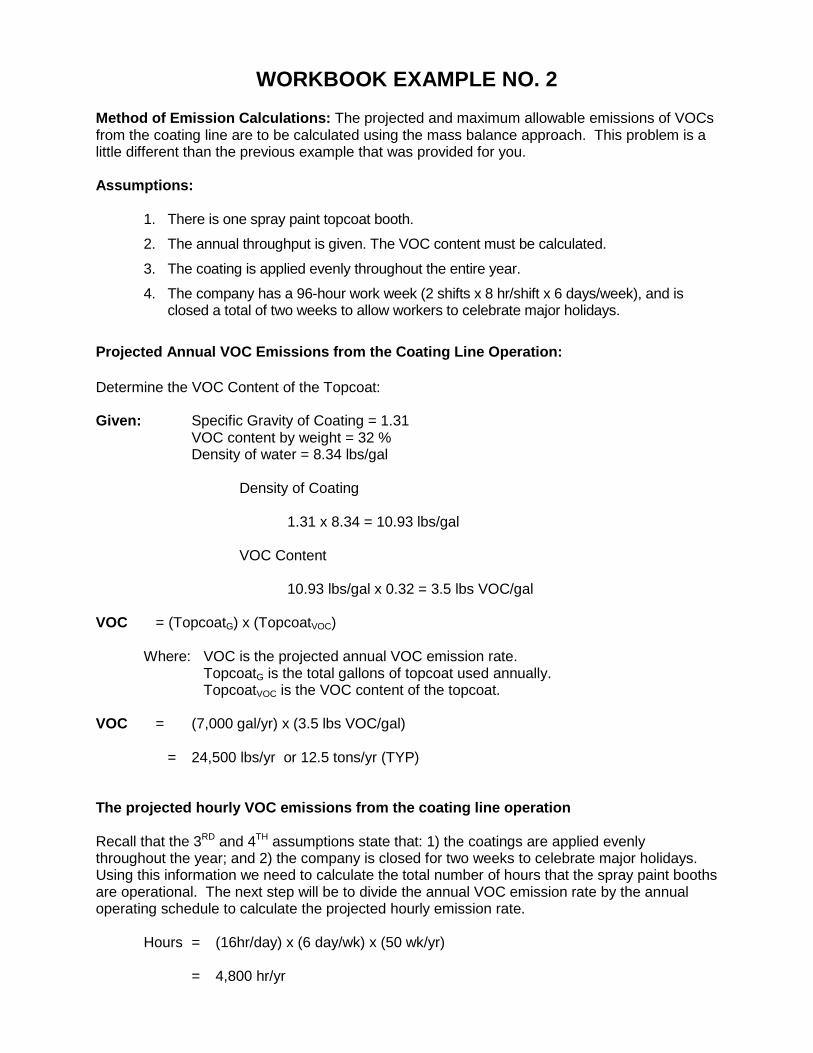
WORKBOOK EXAMPLE NO. 2
Method of Emission Calculations: The projected and maximum allowable emissions of VOCs from the coating line are to be calculated using the mass balance approach. This problem is a little different than the previous example that was provided for you. Assumptions:
1. There is one spray paint topcoat booth.
2. The annual throughput is given. The VOC content must be calculated.
3. The coating is applied evenly throughout the entire year.
4. The company has a 96-hour work week (2 shifts x 8 hr/shift x 6 days/week), and is closed a total of two weeks to allow workers to celebrate major holidays.
Projected Annual VOC Emissions from the Coating Line Operation: Determine the VOC Content of the Topcoat: Given: Specific Gravity of Coating = 1.31 VOC content by weight = 32 % Density of water = 8.34 lbs/gal Density of Coating 1.31 x 8.34 = 10.93 lbs/gal VOC Content 10.93 lbs/gal x 0.32 = 3.5 lbs VOC/gal VOC = (TopcoatG) x (TopcoatVOC)
Where: VOC is the projected annual VOC emission rate. TopcoatG is the total gallons of topcoat used annually.
TopcoatVOC is the VOC content of the topcoat.
VOC = (7,000 gal/yr) x (3.5 lbs VOC/gal) = 24,500 lbs/yr or 12.5 tons/yr (TYP)
The projected hourly VOC emissions from the coating line operation Recall that the 3RD and 4TH assumptions state that: 1) the coatings are applied evenly throughout the year; and 2) the company is closed for two weeks to celebrate major holidays. Using this information we need to calculate the total number of hours that the spray paint booths are operational. The next step will be to divide the annual VOC emission rate by the annual operating schedule to calculate the projected hourly emission rate.
Hours = (16hr/day) x (6 day/wk) x (50 wk/yr)
= 4,800 hr/yr
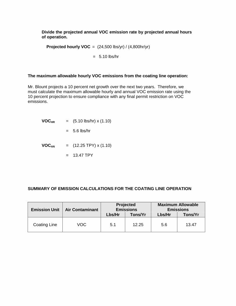
Divide the projected annual VOC emission rate by projected annual hours of operation. Projected hourly VOC = (24,500 lbs/yr) / (4,800hr/yr)
= 5.10 lbs/hr
The maximum allowable hourly VOC emissions from the coating line operation: Mr. Blount projects a 10 percent net growth over the next two years. Therefore, we must calculate the maximum allowable hourly and annual VOC emission rate using the 10 percent projection to ensure compliance with any final permit restriction on VOC emissions.
VOCHR = (5.10 lbs/hr) x (1.10) = 5.6 lbs/hr
VOCAN = (12.25 TPY) x (1.10) = 13.47 TPY
SUMMARY OF EMISSION CALCULATIONS FOR THE COATING LINE OPERATION
Emission Unit Air Contaminant Projected
Emissions Maximum Allowable
Emissions Lbs/Hr Tons/Yr Lbs/Hr Tons/Yr
Coating Line
VOC 5.1 12.25 5.6 13.47

WORKBOOK EXAMPLE NO. 3
When calculating the emissions of a specific compound, keep in mind the following:
1) Always use the maximum percentage when a range is given for a compound.
2) Determine if other coatings contain the same pollutant, in this case ethylene glycol. If so, include those emissions in the calculations.
3) Use the maximum allowable usage rate requested in the permit application.
1. Calculate the annual maximum allowable emissions of ethylene glycol from the coating operation using the above Material Safety Data Sheet (MSDS).
VOCEG = (TopcoatG) x (TopcoatD) x (% TAC) x (SF)
Where: VOCEG is the annual maximum allowable ethylene glycol emission rate TopcoatG is the total gallons of topcoat used annually TopcoatD is the density (in pounds per gallon) of the topcoat % TAC is the percent by weight of ethylene glycol SF is the safety factor (10%) used to calculate the maximum
allowable
VOCEG = (5,000 gal/yr) x (9.84 lb/gal) x (0.10) x (1 + 0.1) = 5,412 pounds per year or 2.71 tons per year
2. Calculate the hourly maximum allowable emissions of ethylene glycol from the coating operation using the above operating schedule.
Calculate the maximum allowable hourly emission rate of ethylene glycol by dividing the annual maximum allowable emission rate by the annual hours of operation.
Hours = (16 hr/day) x (6 day/wk) x (50 wk/yr) = 4,800 hr/yr
Divide the annual maximum allowable ethylene glycol emission rate by the annual hours of operation.
VOCHR = (5,412 lb/yr) / (4,800 hr/yr) = 1.13 lb/hr

3. Apply the Exemption Criteria in Rule 224
Is ethylene glycol a high concern toxic air contaminant?
No, ethylene glycol is not listed in Table 20 of Rule 226. Is the emission of ethylene glycol less than 10 pounds per month and 0.14 pounds per hour?
No.
The monthly emissions are 5.412 lbs/yr * 1 yr/12 months = 451 pounds which is > 10 pounds.
The hourly emissions are 1.13 lbs which is > 0.14
Is the emission of ethylene glycol exempt from the health based screening level requirement? If no, proceed to Question 4.
The ethylene glycol emissions are not exempt from the health-based screening level.
4. Will the emission of ethylene glycol exceed the allowable emission rate (AER)?
Apply the algorithm in Table 21 of Rule 227 to determine the AER. Multiply the screening level of ethylene glycol by 0.001 to determine the AER:
AER = (Screening level for ethylene glycol) x (k)
Note: (k) is a correction factor for the averaging time listed in Table 21.
AER = (1,000 ug/m3) x (0.001 lbs/hr ) µg/m3
= 1.0 lb/hr
Compare the AER to the hourly emission of ethylene glycol. If the emissions are less than the calculated AER, then the source emissions are acceptable.
AER vs. Ethylene Glycol Emissions
1.0 lb/hr < 1.13 lbs/hr The coating line does exceed the AER for ethylene glycol. Try the AIR or SCREEN3 model to show compliance with the screening level requirement of Rule 225.