persona the personalized knee - zimmer biomet...5 | persona the personalized knee surgical technique...
TRANSCRIPT

Persona® The Personalized Knee
Surgical Technique

Table of Contents
Introduction .............................................................................................................. 2 Constraint Options Preoperative Planning Surgical Approach Patient Preparation Magnet Usage Symbols Screw/Pin Information
Resect Distal Femur .................................................................................................. 6 Assemble Adjustable Distal Resection Instrumentation Establish Femoral Alignment Resect Distal Femur Optional Instrument Optional Cutting Technique
Resect Proximal Tibia ............................................................................................. 12 Assemble Extramedullary (EM) Alignment Guide Position Alignment Guide Set Resection Level Resect Proximal Tibia Optional Technique
Size Femur and Establish External Rotation .......................................................... 19
Complete Femoral A/P and Chamfer Resections .................................................. 22 Optional Instrument
Establish Size and Rotation of Tibia ........................................................................ 24
Drill and Broach Tibia.............................................................................................. 25 Optional Technique
Prepare the Patella ................................................................................................. 28
Resect the Patella ................................................................................................... 28
Finish the Patella ..................................................................................................... 29
CR Femoral Finishing and Trialing .......................................................................... 31
PS Femoral Finishing and PS Box Preparation ....................................................... 33
Perform Trial Reduction .......................................................................................... 38

Table of Contents (cont.)
Tibial Articular Surface Provisional (TASP) Assembly ............................................ 39
Implant Components .............................................................................................. 43 Tibial Plate Femoral Component Bearing Patellar Component All-Polyethylene Patella
Close Incision .......................................................................................................... 46 Surgeon Notes and Tips
Appendix A .............................................................................................................. 47 2 Degrees Valgus Recut Guide 2 Degrees Varus Recut Guide
Appendix B .............................................................................................................. 49 Spacer Block Technique
Appendix C: Optional Instruments ......................................................................... 52 Resect Distal Femur: Fixed Distal Resection Instrument Size Femur - Anterior Referencing Sizer Shift Block Resect Distal Femur - PRI Distal Resection Instrument Implant Components - Attached Tibial Plate Inserter
Appendix D ............................................................................................................. 66 Compatibility Charts

2 | Persona The Personalized Knee Surgical TechniqueSurgical Technique
Successful total knee arthroplasty depends in part on re-establishment of normal lower extremity alignment, proper implant design and orientation, secure implant fixation, and adequate soft tissue balancing and stability. Persona The Personalized Knee is designed to help the surgeon accomplish these goals by combining alignment accuracy with a simple, straight-forward technique.
The instruments and technique assist the surgeon in restoring the center of the hip, knee, and ankle to lie in a straight line, establishing a neutral mechanical axis. The femoral and tibial components are oriented perpendicular to this axis. Femoral rotation is determined using the posterior condyles, the epicondylar axis, or Whiteside’s line as a reference. The instruments enable accurate cuts to ensure robust component fixation.
A wide variety of component sizes, shapes, and constraint options allow for optimized component fit and soft tissue balancing. The femur, tibia, and patella are prepared independently, and can be cut in any sequence using the principle of measured resection (removing enough bone to allow replacement by the prosthesis). Adjustment cuts may be needed later. The anterior referencing technique uses the anterior cortex to set the A/P position of the femoral component. The posterior condyle cut is variable.
Constraint Options
The degree of constraint of the bearing can be planned based on surgeon preference and patient requirements. The use of the cruciate retaining (CR) femoral provisionals and components can be used with either a CR or Medial Congruent® (MC) bearing when the posterior cruciate ligament (PCL) is intact.
The CR femoral provisionals and components can be used when the PCL is sacrificed or deficient and removed, if used with either a MC or ultracongruent (UC) bearing provisionals and components.
Also, posterior stabilized (PS) femoral provisionals and components can be used with the PS or constrained posterior stabilized (CPS) bearings provisionals and components when the PCL is deficient and removed.
PS femoral components cannot be used with CR, MC, or UC bearings and CR femoral components cannot be used with PS or CPS bearings.
The CPS bearings can be used to provide moderate varus\valgus constraint in patients to facilitate soft tissue balance and stability. The CPS bearings shall be used with cemented non-porous femoral and tibial components only. Additional information for this product may be found in the Constrained Posterior Stabilized (CPS) Surgical Technique (97-5026-072-00).
The MC, UC, PS, and CPS implants can be used in the following situations, depending on the degree of the deformity, the stability of the ligaments, and the quality of the bone. The surgeon is responsible for assessing whether a more constraining implant/system or revision implant/system is necessary.
1. Marked valgus deformity – requiring PCL and lateral soft tissue release.
2. Prior high tibial osteotomies – soft tissue balancing is the same as for a valgus deformity with lateral soft tissue and PCL release.
3. Patellectomy – PCL incomplete or absent.
4. Most revision situations – PCL deficient or nonfunctional.
Introduction

3 | Persona The Personalized Knee Surgical Technique
Introduction (cont.)
Note: The MC components can be used with or without the PCL present. The UC, PS, and CPS components should not be used if the PCL is present.
Please refer to the package inserts for complete product information, including contraindications, warnings, precautions, and adverse effects.
Preoperative Planning
Obtain 36 inch or 53 inch standing anteroposterior and lateral radiographs of the extremity, as well as a sunrise view of the patella. The entire femur should be visualized to rule out any structural abnormalities, as the distal femoral cut will be referenced from an intramedullary rod in the medullary canal.
Use the template overlay (available through your Zimmer Biomet representative) to determine the angle between the anatomic axis and the mechanical axis. This angle will be reproduced intraoperatively. This surgical technique helps the surgeon ensure that the distal femur will be cut perpendicular to the mechanical axis and, after soft tissue balancing, will be parallel to the resected surface of the proximal tibia.
Surgical Approach
The surgeon can choose a midvastus approach, a subvastus approach, or a parapatellar medial arthrotomy. Also, depending on surgeon preference, the patella can be either everted or subluxed. The femur, tibia, and patella are prepared independently, and can be cut in any sequence using the principle of measured resection (removing enough bone to allow replacement by the prosthesis).
Patient Preparation
To prepare the limb for total knee arthroplasty, adequate muscle relaxation is required. The anesthesiologist should adjust the medication based on the patient’s habitus and weight, and administer to induce adequate muscle paralysis for a minimum of 30-40 minutes. It is imperative that the muscle relaxant be injected prior to inflation of the tourniquet. Alternatively, spinal or epidural anesthesia should produce adequate muscle relaxation. If desired, apply a proximal thigh tourniquet and inflate it with the knee in hyperflexion to maximize that portion of the quadriceps that is below the level of the tourniquet. Once the patient is draped and prepped on the operating table, determine the landmarks for the surgical incision.

4 | Persona The Personalized Knee Surgical Technique
Magnet Usage
Warning: Some instruments in the Persona System contain magnets. All Persona Magnetic Instruments should be kept at a safe distance from a patient’s active implantable medical device(s) (i.e. pacemaker). These types of devices may be adversely affected by magnets. Instruments containing magnets should be kept on an appropriate table or stand when not in use at the surgical site.
Symbols
Symbols have been established for the following:
• Left
• Right
• Varus/Valgus
• Medial/Lateral
• Standard
• Do not implant - Not for implant
• Do not impact
• Inset Only
• Anterior Referencing
• Lock
• Unlock
• Cemented
• Stemmed
• Narrow
Introduction (cont.)
Lock Unlock
Medial/Lateral
M/LStandard
StdDo not implant - Not for implant
Left Right Varus/Valgus
Cemented Stemmed
Do not impact Inset Only Anterior Referencing
Narrow

5 | Persona The Personalized Knee Surgical Technique
* The 2.5 mm female hex screws and 2.5 mm male hex driver should not be used in cortical bone, as this may increase the incidence of stripping of the driver.
Screw/Pin Information
The chart below contains relevant information on various 3.2 mm screws/pins that are compatible with the Persona System. If these screws/pins are used during the procedure for instrument fixation, they should be removed prior to closure as they are NOT implantable.
Screw/Pin Screw/Pin Item # Compatible DriverShipped Sterile/Non-sterile
Quantity per Package Single use?
25 mm x 2.5 mm Female Hex Screw 42-5099-025-25*
2.5 mm Male Hex Driver 42-5099-025-00
Sterile 2 Yes
75 mm x 3.2 mm Trocar Tipped Drill Pin (2.5 mm hex) 00-5901-020-00
Pin/Screw Inserter 00-5901-021-00
Sterile 4 Yes
Hex Headed Screw 33 mm long 00-5901-035-33
Pin/Screw Inserter 00-5901-021-00
Sterile 2 Yes
MIS Quad-Sparing™ Total Knee Headed Screw 48 mm long 00-5983-040-48
Screw Inserter/Extractor00-5983-049-00
Sterile 1 Yes
25 mm Shorthead Holding Pin 00-5977-056-03 Multi Pin Puller
00-5901-022-00
Non-Sterile 1 No
Introduction (cont.)

6 | Persona The Personalized Knee Surgical Technique
1. Pull
2. Insert
2. Rotate
1. Press
Caution Marking
Rotate Dial
Shown at '0' setting
Figure 1
Figure 2
Figure 3
Figure 4
Insert the IM rod into the adjustable valgus guide.
Note: If desired, align the depth markings on the IM rod with the flat plate of the adjustable valgus guide to set the IM rod at a specific length. Inserting the IM rod beyond the double line marking, indicated with caution symbols, may prevent assembly of the modular handle to the IM rod (Figure 3).
Refer to Appendix C for Optional Instruments to resect the distal femur.
Set the resection depth on the adjustable resection tower by rotating the dial (Figure 4). The ‘0’ setting indicates a 10 mm resection. Adjustments can be made in 1 mm increments from 10 mm to 14 mm.
Resect Distal FemurAssemble Adjustable Distal Resection Instrumentation
Pull the lever on the modular handle and insert the IM rod (Figure 1). Orientation of the IM rod will align with the polished line on the sides of the modular handle.
Technique Tip: Alternately, the IM rod may be inserted into the top of the modular handle to accommodate surgical preference.
Set the valgus angle on the adjustable valgus guide by pressing the button and rotating the dial to the appropriate left or right valgus angle from 0 degrees to 9 degrees (Figure 2).
Avoid turning the locking knob excessively in the counterclockwise, or "unlocking", direction to prevent it from binding.
Persona 8 mm IM Rod 42-5099-002-00
Persona Modular Handle 42-5099-014-00
Persona Valgus Alignment Guide42-5099-004-00
Persona Adjustable Resection Tower42-5099-008-00

7 | Persona The Personalized Knee Surgical Technique
Resect Distal Femur (cont.)Assemble Adjustable Distal Resection Instrumentation (cont.)
Note: The ‘0’ setting can be set to indicate a 1 mm through 9 mm resection depth, in 1 mm increments, by assembling the corresponding resection plate to the valgus guide. Figure 5 illustrates this with the 9 mm resection plate. The 9 mm and 8 mm resection plates may facilitate correction of recurvatum and the 1 mm–3 mm resection plates can be used for recutting the distal femur, if needed.
The size 1 and 2 femoral components are 1 mm thinner distally than sizes 3-12. Consider adjusting the resection depth on these sizes to accommodate for this difference.
Technique Tip: If it is possible that the femoral component may be a size 1 or 2, then consider cutting the distal resection for a size 1 or 2. If the size of the femur is later determined to be 3-12, then the additional bone cut can be made using the 1 mm resection plate.
Insert the adjustable resection tower into the adjustable valgus guide.
Rotate the lock lever on the adjustable resection tower to the unlocked, or “in-line”, position and fully insert into the cut guide (Figure 6a). Flip the lock lever to the locked, or “vertical”, position to secure it to the cut guide (Figure 6b).
Technique Tip: The adjustable resection tower is compatible with the fixed valgus guide and the fixed resection tower is compatible with the adjustable valgus guide. These instruments can be interchanged to accommodate surgical preference.
Figure 5
Figure 6a
Figure 6b
2. Insert 1. Unlock
Lock
Persona 8 mm IM Rod 42-5099-002-00
Persona Modular Handle 42-5099-014-00
Persona Valgus Alignment Guide 42-5099-004-00
Persona Adjustable Resection Tower 42-5099-008-00
Persona 0° Distal Cut Guide 42-5099-010-00
Persona 9 mm Distal Resection Plate 42-5099-015-09

8 | Persona The Personalized Knee Surgical Technique
Resect Distal Femur (cont.)Establish Femoral Alignment
Drill the IM canal using the 8 mm IM step drill (Figure 7). Suction the canal to remove medullary contents.
Insert the IM rod and assembled distal resection instrumentation into the IM canal far enough to ensure the most accurate replication of the anatomic axis.
Set the orientation of the adjustable valgus guide by placing it against the most prominent distal condyle and rotating it about the IM rod so that the engraved lines are aligned with the epicondylar axis (Figure 8a).
Turn the lock knob on the adjustable valgus guide clockwise, to the locked position, to secure orientation of the assembly (Figure 8b).
Note: Setting rotation of the adjustable valgus guide is important for creating a distal resection that matches the desired valgus angle selected. It does not set the rotation of the femoral component.
Figure 7 Figure 8a Figure 8b
8 mm IM Step Drill
00-5978-014-00
Persona 8 mm IM Rod 42-5099-002-00
Persona Modular Handle 42-5099-014-00
Persona Valgus Alignment Guide42-5099-004-00
Persona Adjustable Resection Tower 42-5099-008-00
Persona 0° Distal Cut Guide 42-5099-010-00

9 | Persona The Personalized Knee Surgical Technique
Resect Distal Femur (cont.)
Establish Femoral Alignment (cont.)
For additional fixation, or in lieu of using the lock knob, impact the captured pin on the medial or lateral side of the adjustable valgus guide until the head of the captured pin is flush with the plate (Figure 9).
Resect Distal Femur
Verify the adjustable valgus guide is set to the proper side (left or right) and angle and that the adjustable resection tower is set to the appropriate depth.
Figure 9
Technique Tip: If unsure of the adjustable resection tower depth setting, rotate the dial clockwise until a “click” is felt. This occurs when the dial moves from the ‘4’ setting to the ‘0’ setting. The bold ‘0’ will be visible on the dial and the line will be aligned with the ‘0’ mark along the shaft (Figure 10).
Technique Tip: Confirm valgus alignment by inserting the drop rod adapter into the large holes on the anterior face of the cut guide and insert an alignment rod into the drop rod adapter (Figure 11).
Rotate Dial
"Click"
Figure 10 Figure 11
Persona 8 mm IM Rod 42-5099-002-00
Persona Modular Handle 42-5099-014-00
Persona Valgus Alignment Guide 42-5099-004-00
Persona Adjustable Resection Tower 42-5099-008-00
Persona 0° Distal Cut Guide 42-5099-010-00
Persona Drop Rod Adapter 42-5399-006-00
Alignment Rod with Coupler 00-5785-080-00

10 | Persona The Personalized Knee Surgical Technique
Resect Distal Femur (cont.)Resect Distal Femur (cont.)
Insert a trocar tipped pin through each of the standard pin holes marked ‘0’ on the anterior surface of the cut guide (Figure 12).
Flip the lock lever on the adjustable resection tower to the unlocked, or “in-line”, position and pull the handle to remove the IM rod and assembled distal resection instrumentation leaving only the cut guide attached to the femur (Figure 13).
Note: If the captured pin was deployed it may be necessary to first remove it from the bone using the pin puller. Alternatively, removing the IM rod from the adjustable valgus guide may facilitate removal of the captured pin from the bone.
Optional Instrument
A fixed distal resection system exists for users who, for all patients, maintain a consistent valgus angle for their distal cut. For use of this instrument refer to Appendix C: Optional Instruments: Resect Distal Femur - Fixed Distal Resection Instrument Section 1.
Technique Tip: Additional 2 mm adjustments may be made by using the sets of holes marked -2, +2, and +4. These sets of holes indicate, in millimeters, the amount of additional bone resection each will yield relative to the resection setting on the resection tower (where ‘0’ represents 10 mm. However, if the 9 mm resection plate is used, the ‘0’ represents 9 mm).
1. Unlock
2. Pull
Figure 12 Figure 13
Persona 8 mm IM Rod 42-5099-002-00
Persona Modular Handle 42-5099-014-00
Persona Valgus Alignment Guide42-5099-004-00
Persona Adjustable Resection Tower 42-5099-008-00
Persona 0° Distal Cut Guide 42-5099-010-00
3.2 mm x 75 mm Trocar Tipped Drill Pin (2.5 mm hex) 00-5901-020-00
Pin Screw Inserter 00-5901-021-00

11 | Persona The Personalized Knee Surgical Technique
Resect Distal Femur (cont.)Optional Instrument (cont.)
Insert the resection guide into the cut slot of the cut guide to verify the depth of resection.
Insert a trocar tipped pin through at least one of the locking, or oblique, pin holes in the cut guide to further secure the cut guide to the femur (Figure 14).
Using a 1.27 mm (0.050 inch) oscillating saw blade through the cut slot in the cut guide, resect the distal femur.
Note: The flatness of the distal femoral resection is critical to ensuring adequate contact between the porous femoral implant and the bone. If using a porous femoral implant, evaluate the flatness of the resection prior to sizing and modify the cut as necessary so that it is completely flat.
Remove all pins and the cut guide.
Optional Cutting Technique
If desired, the bone resection can be made from the top (most distal) surface of the cut guide (Figure 15a). The top surface of the cut guide is 4 mm from the cut slot. Therefore, if cutting from the top surface, the position of the cut guide must be adjusted by moving the cut guide from the trocar tipped pins through the ‘0’ holes and reinserting the cut guide onto the trocar tipped pins through the holes marked ‘+4’ (Figure 15b). Insert a trocar tipped pin through at least one of the locking, or oblique, pin holes in the cut guide to further secure the cut guide to the femur prior to cutting the femur.
Figure 14
Figure 15b
Figure 15a
Persona 0° Distal Cut Guide 42-5099-010-00
3.2 mm x 75 mm Trocar Tipped Drill Pin (2.5 mm hex)
00-5901-020-00
Pin Screw Inserter
00-5901-021-00
Resection Guide 00-5977-084-00
Multi Pin Puller 00-5901-022-00
Persona 8 mm IM Rod 42-5099-002-00
Persona Modular Handle 42-5099-014-00
Persona Valgus Alignment Guide42-5099-004-00
Persona Adjustable Resection Tower 42-5099-008-00

12 | Persona The Personalized Knee Surgical Technique
1. Push
3. Release
4. Push
6. Release
2. Insert Rod
5. Insert
Resect Proximal TibiaAssemble Extramedullary (EM) Alignment Guide
Depress and hold the button on the EM distal rod and insert the threaded rod on the EM ankle clamp into the distal rod and release the button. Depress and hold the button on the distal end of the EM proximal tube and insert the EM distal rod into the EM proximal tube and release the button (Figure 16).
Attach the selected tibial cut guide to the EM alignment guide (Figure 17).
1. Lift the lever on the EM proximal tube up.
2. Translate the cut guide onto the top of the EM proximal tube, under the locking cone.
3. Push down the lever on the EM proximal tube to lock the cut guide in place.
Figure 16 Figure 17
3. Push Down2. Translate
1. Lift
Persona EM Proximal Tube 42-5399-001-00
Persona EM Distal Rod 42-5399-002-00
Persona EM Ankle Clamp 42-5399-003-00
Persona Tibial Cut Guide Left - 3° 42-5399-051-03
Persona Tibial Cut Guide Left - 7° 42-5399-051-07

13 | Persona The Personalized Knee Surgical Technique
Figure 18 Figure 19
Resect Proximal Tibia (cont.)Assemble Extramedullary (EM) Alignment Guide (cont.)
The buttons shown in Figure 18 are used to adjust the following: varus/valgus angle of the cut guide, slope of the cut guide and the height of the cut guide. The height adjustment button can be depressed for macro-adjustment or the dial can be rotated for micro-adjustment.
One full rotation of the dial equals 4 mm of height adjustment and ¼ turn equals 1 mm of height adjustment (Figure 19). Rotating the height adjustment dial clockwise shortens the alignment guide and rotating the dial counterclockwise lengthens the alignment guide.
The system includes six different cut guides: a 7 degree cut guide and a 3 degree guide, in left, right, and universal (non-sided) configurations.
Technique Tip: It is recommended to use the 3 degree cut guide for a PS component and the 7 degree cut guide for a CR component. If the UC bearing is to be used, the recommended tibial cut slope is 5–7 degrees. Biasing towards a flatter slope cut for the UC bearing provides an opportunity to better match flexion and extension space, considering the flexion space generally increases more than the extension space when the PCL is resected. If the MC bearing is used, the recommended tibial slope is 5 degrees. However, 7 degrees is allowable particularly when the PCL is retained.
Height Adjustment
Varus/Valgus Adjustment
Slope Adjustment
Shorten
Clockwise
Counter Clockwise
Lengthen
Persona Tibial Cut Guide Right - 3° 42-5399-052-03
Persona Tibial Cut Guide Right - 7° 42-5399-052-07
Persona Tibial Cut Guide Universal - 3° 42-5399-050-03
Persona Tibial Cut Guide Right - 7° 42-5399-050-07

14 | Persona The Personalized Knee Surgical Technique
Resect Proximal Tibia (cont.)Position Alignment Guide
To improve the exposure of the tibial surface, retract the tibia anteriorly. Carefully position the retractor against the posterior cortex of the tibia subperiosteally to prevent neurovascular injury. Retract the patella laterally. Adjust the EM alignment guide to the approximate length of the tibia. Place the spring arms of the EM ankle clamp around the ankle proximal to the malleoli. Align the vertical slot in the cut guide with the medial third of the tibial tubercle.
Technique Tip: Care should be taken when pinning into the tibia to avoid perforating the posterior cortex.
Adjust the height of the cut guide to the approximate desired location. Use the engraved line on the top of the cut guide to align the rotational and M/L placement guide (Figure 20b). A 3.2 mm pin or screw may be inserted through the 12 mm vertical slot in the cut guide to secure the desired M/L and rotational position of the proximal portion of the guide (Figure 20a).
Note: This pin will need to be removed to allow the "+2" or "+4" mm shifts with the cut guide.
Align the EM alignment guide with the mechanical axis of the tibia (Figure 21a). The longitudinal axis will usually lie just medial to the mid-point of the tibial tubercle and be centered in line with the intercondylar eminence. The distal end of the EM alignment guide should be positioned about 5 mm–10 mm medial to the midpoint between the palpable medial and lateral malleoli. The short vertical engraved lines on the varus/valgus adjustment rail are incremented by 5 mm to aid in setting the desired varus/valgus position of the EM alignment guide (Figure 21b). Excessive soft tissue or poor exposure or visualization can make it difficult to palpate bony landmarks so care should be taken to ensure accurate cuts.
Figure 20b Figure 21b
Figure 20a
Figure 21a
AP Axis
5 mm
3.2 mm x 75 mm Trocar Tipped Drill Pin (2.5 mm hex)
00-5901-020-00
Pin Screw Inserter
00-5901-021-00
Persona Tibial Cut Guide Right - 7° 42-5399-052-07
Persona EM Proximal Tube 42-5399-001-00
Persona EM Distal Rod 42-5399-002-00
Persona EM Ankle Clamp 42-5399-003-00
3.2 mm Drill 00-5120-085-00

15 | Persona The Personalized Knee Surgical Technique
Resect Proximal Tibia (cont.)Position Alignment Guide (cont.)
Adjust the EM alignment guide in the sagittal plane to be parallel to the anterior tibial crest. A 3.2 mm drill or the 3.2 mm pin can be placed through the hole in the slot of the cut guide to help assess the expected slope of the tibial resection, and if desired, match the patient's specific anatomic slope (Figure 22). As necessary, adjust the tibial slope of the EM alignment guide. If there is bulky bandage around the ankle or if there is excessive adipose tissue, the guide can be adjusted to create the desired slope. This will help ensure that the tibia will be cut with the proper slope. Care should be taken to avoid excessive posterior slope and to verify coronal alignment to the mechanical axis.
Figure 22 Figure 23
Set Resection Level
Each tip of the stylus indicates a different resection level. The 2 mm tip is used to establish the resection level from the defective tibial condyle for a minimal cut. The 10 mm tip is used to establish the resection level from the least involved tibial condyle.
To assemble, push and hold the lever on the stylus and insert the stylus into the top of the cut guide and release the lever (Figure 23). The stylus rotates and telescopes to facilitate desired positioning of the stylus tip.
Technique Tip: Boom tip must be in the vertical position to accurately assess resection level. Correct position is verified with an audible click as the boom twists. WARNING: An excessive bone resection will result if the boom is not in the vertical position.
Technique Tip: If using the top surface of the cut guide to make the resection, follow this technique for setting the resection level with the stylus. Then follow the optional technique at the end of this section. The stylus tips are calibrated to the cut slot.
2. Insert
1. Push
3. Release
Persona Tibial Cut Guide Right - 7° 42-5399-052-07
Persona Tibial Stylus - 2/10 mm 42-5399-005-00

16 | Persona The Personalized Knee Surgical Technique
Pin/Screw Inserter 00-5901-021-00
Alignment Rod with Coupler 00-5785-080-00
Persona Tibial Cut Guide Right - 7° 42-5399-052-07
Persona Tibial Stylus - 2/10 mm 42-5399-005-00
Persona Drop Rod Adapter 42-5399-006-00
75 mm x 3.2 mm Trocar Tipped Drill Pin (2.5 mm hex)00-5901-020-00
Resection Guide00-5977-084-00
Figure 24 Figure 25
Figure 27
Figure 28
A resection guide can be placed through the cut slot on the cut guide, to verify the desired level and slope of the resection (Figure 26). Insert a 3.2 mm trocar tipped pin through one of the "0" holes in the cut guide with the pin/screw inserter. Ensure the cut guide is flush to the bone and not impeded by soft tissues before making the cut.
Insert a second trocar tipped pin through the other "0" hole in the cut guide with the pin/screw inserter (Figure 27). Remove the stylus by pushing the lever on the side of the stylus and remove.
To confirm alignment, insert the drop rod adapter into the cut guide and insert the alignment rod into the adapter (Figure 28).
Figure 26
Resect Proximal Tibia (cont.)Set Resection Level (cont.)
The 2 mm tip should rest on the defective tibial condyle (Figure 24). This positions the slot of the cut guide to remove 2 mm of bone below the tip of the stylus.
Alternatively, rest the 10 mm tip of the stylus on the cartilage of the least involved condyle (Figure 25). This will allow the removal of the same amount of bone that the thinnest tibial component will replace. These two points of resection will usually not coincide. The surgeon must determine the appropriate level of resection based on patient’s needs, such as age and bone quality. Rotate the micro-adjustment dial of the EM proximal tube to position the stylus and the cut guide to the desired level.
Technique Tip: When adjusting the height of the EM alignment guide steady the distal portion of the guide with one hand and use the other hand to adjust the height of the proximal portion of the guide.

17 | Persona The Personalized Knee Surgical Technique
Persona Tibial Cut Guide Right - 7° 42-5399-052-07
75 mm x 3.2 mm Trocar Tipped Drill Pin (2.5 mm hex) 00-5901-020-00
Pin/Screw Inserter 00-5901-021-00
Multi Pin Puller 00-5901-022-00
Figure 30a Figure 30b
Figure 29 Figure 31
Figure 32
Resect Proximal Tibia (cont.)Resect Proximal Tibia
The entire EM alignment guide can be left in place for additional stability during resection. Optionally, the EM alignment guide can be removed by lifting the lever on the EM proximal tube up to the open position, translating the EM alignment guide anteriorly while leaving the cut guide in place (Figure 29). If the EM alignment guide has been removed, additional 2 mm adjustments may be made by shifting the cut guide to the sets of holes marked “+2”, and “+4”. The markings on the cut guide indicate, in millimeters, the amount of additional bone resection relative to the standard tibial resection set by the cut guide and stylus. If a pin or screw was inserted into the 12 mm vertical slot, it will need to be removed to make the 2 mm adjustments.
Once the resection level has been determined, insert a 3.2 mm trocar tipped pin in the oblique hole indicated by a lock pin symbol, to further secure the cut guide (Figures 30a and 30b). If a pin or screw was inserted into the 12 mm vertical slot, then a pin through the oblique hole may not be needed for secure fixation.
Optional Technique
If desired, the resection can be made from the top surface of the cut guide. The top surface of the cut guide is 4 mm above the cut slot (Figure 31); therefore, the position of the cut guide must be adjusted by moving the cut guide from the headless pins and reinserting the cut guide through the holes marked "+4" (Figure 32).
1. Lift
2. Translate
Locking Pin Symbol

18 | Persona The Personalized Knee Surgical Technique
Resect Proximal Tibia (cont.)Optional Technique (cont.)
Technique Tip: The patellar tendon may be located behind the lateral side of the cut guide due to the patellar tendon relief cutout on the cut guide. Be careful to avoid cutting the patellar tendon when resecting the tibia.
Use a 1.27 mm (0.050 inch) oscillating saw blade through the slot on the cut guide to resect the proximal surface of the tibia (Figure 33).
Prior to removing the cut guide, a contralateral or universal cut guide (of any angle) can be inverted and placed on the resected tibia to assure that a planar cut has been achieved (Figure 34). If necessary, perform a clean-up cut.
Note: The flatness of the proximal tibial resection is critical to ensuring adequate contact between the porous tibial implant and the bone. If using a porous tibial implant, evaluate the flatness of the proximal tibial resection prior to drilling for the pegs. Modify the cut as necessary so that it is completely flat.
Remove oblique pins and the tibial cut guide.
Technique Tip: If unable to complete the resection on the lateral side of the tibia, remove the cut guide, extend the knee and retract the soft tissue on the lateral side. If necessary, use an osteotome to complete the resection.
If the cut guide has been removed, the drop rod adapter and alignment rod can be inserted into the holes on the inverted contralateral or universal cut guide (of any angle) to verify the desired tibial resection (Figure 35).
Remove all pins.
Figure 33 Figure 34 Figure 35
Persona Tibial Cut Guide Right - 7° 42-5399-052-07
Persona Tibial Cut Guide Universal - 3° 42-5399-050-03
Persona Tibial Cut Guide Universal - 7° 42-5399-050-07
75 mm x 3.2 mm Trocar Tipped Drill Pin (2.5 mm hex) 00-5901-020-00
Multi Pin Puller 00-5901-022-00
Persona Drop Rod Adapter 42-5399-006-00
Alignment Rod with Coupler 00-5785-080-00
Pin/Screw Inserter 00-5901-021-00

19 | Persona The Personalized Knee Surgical Technique
Persona Anterior Referencing Sizer 42-5099-088-10
2.5 mm Male Hex Driver 42-5099-025-00
25 mm x 2.5 mm Female Hex Screw 42-5099-025-25
Size Femur and Establish External Rotation Rotate the feet of the anterior referencing femoral sizing guide so the appropriate “Left” or “Right” markings are visible as the femoral sizing guide is placed on the bone (Figure 36). External rotation can be set at 3 degrees or 5 degrees from the posterior condylar axis.
Technique Tip: Remove any osteophytes that interfere with instrument positioning.
Apply the sizer so that the flat surface of the sizer is flush against the resected surface of the distal femur and the feet of the sizer are flush against the posterior condyles. Center the sizer mediolaterally. Both the vertical and horizontal portions of the sizer provide visual cues relative to the A/P and epicondylar axes of the femur to help ensure that desired external rotation is attained.
Note: Sizer geometry is rotated 3 degrees to align to the A/P and epicondylar axes of the femur. The 3 degrees drill holes are rotated 3 degrees from the posterior feet and are neutral to the central sizer geometry. This enables use of the A/P and epicondylar axis to set rotation.
Side Designation
Figure 36
Figure 37
Figure 38
If the 3 degrees external rotation holes are to be used to set external rotation, the etched line on the sizer should be positioned so it is in line with Whiteside’s line (Figure 37) to optimize the M/L position of the drill holes for subsequent 4-in-1 cut guide placement. If the 5 degrees external rotation holes are to be used, the sizer can be positioned with the etched line on the sizer 4 mm laterally from Whiteside’s line to better center the drill holes for subsequent 4-in-1 cut guide placement, due to the M/L offset of the holes. Hold the guide in place and if necessary, secure the sizer to the femur using 25 mm x 3.2 mm (2.5 mm female hex) screws (Figure 38) in one or both of the holes on the lower portion of the guide to help draw the sizer adjacent to the distal femur, particularly in MIS situations.
Note: Do NOT use 48 mm screws for fixation of the anterior reference sizer. 48 mm screws are not recommended due to potential bone perforation.
Technique Tip: Do not impact the sizer onto the femur.

20 | Persona The Personalized Knee Surgical Technique
25 mm x 2.5 mm Female Hex Screw 42-5099-025-25
3.2 mm Drill 00-5120-085-00
2.5 mm Male Hex Driver 42-5099-025-00
Persona Anterior Referencing Sizer 42-5099-088-10
Size 1Size 7
Size 12
Size Femur and Establish External Rotation (cont.)
Slightly extend the knee and retract soft tissues to expose the anterior femoral cortex. Clear any soft tissue from the anterior cortex. Ensure that the leg is in less than 90 degrees of flexion (70 degrees– 80 degrees). This will decrease the tension of the patellar tendon to facilitate placement of the sizing boom. The sizing boom telescopes proximally/distally to facilitate optimal placement along the anterior cortex. The engraved lines along the top of the boom approximate the anterior flange lengths of the size 1, 7, and 12 femoral components (Figure 39a). Once the sizing boom is appropriately positioned, it should be locked in place by tightening the knob at the end of the boom clockwise (Figure 39b).
Technique Tip: Lock boom after positioning to reduce the toggle of the boom tip. This will also reduce the risk of notching.
Technique Tip: Positioning the sizing boom tip on the “high” part of the femur by lateralizing the location of the sizing boom tip can often lessen the likelihood of notching the femur.
Technique Tip: To size accurately, the sizing boom should be telescoped to the size read from the tower. If the boom is telescoped to the exact size, the tip of the boom will approximate the exit point of the saw blade through the anterior cortex.
Figure 39bFigure 39a

21 | Persona The Personalized Knee Surgical Technique
Figure 40 Figure 41
Size Femur and Establish External Rotation (cont.)
After the sizer is appropriately positioned on the femur, read the femoral size from the engraved lines on the sizer tower and select the closest size (Figure 40). There are six even sizes labeled on the left side of the tower and six odd sizes labeled on the right side of the tower, with lines indicating the in-between sizes. The 3 degrees or 5 degrees holes in the midline of the A/P portion of the sizer are used to drill 3.2 mm holes for pegs on the anterior referencing 4-in-1 femoral cut guide (Figure 41). A 3.2 mm pin may be placed in the first drilled hole to maintain an “index” position prior to drilling the second hole. Remove the screws, then remove the sizer.
Technique Tip: The multi pin puller cannot be used to extract the screw(s).
Technique Tip: This anterior referencing sizer works only with these anterior referencing 4-in-1 femoral cut guides and provisionals, and implants referenced in this technique.
Technique Tip: If the femoral size is determined to be a size 3 or bigger but was prepared for a size 1 or 2, consider cutting additional distal bone using the 1 mm resection plate.

22 | Persona The Personalized Knee Surgical Technique
Persona Anterior Referencing 4-in-1 Cut Guide - Size 7 42-5099-085-62
Resection Guide 00-5977-084-00
3.2 mm Drill 00-5120-085-00
Persona Slaphammer 42-5099-037-00
1. Insert
Complete Femoral A/P and Chamfer Resections By hand, place the 4-in-1 cut guide on the femur by aligning the two pins on the back of the guide with the previously drilled positioning holes (Figure 42). Impact the face of the guide until the guide is flush with the femur. Place the resection guide through the anterior slot of the cut guide to ensure the desired anterior resection (Figure 43). If inadequate bone will be removed from the anterior cortex, drill through the two holes on the face of the cut guide (Figure 44a). Use the slaphammer to axially remove the cut guide (Figures 45a and 45b). Place the next smaller-sized femoral cut guide on the femur in the newly drilled “posteriorized” drill holes (Figures 44a and 44b). Verify the anterior and posterior resection levels with the resection guide to assure that the desired resections will be attained. If too much posterior bone will be resected the original femoral cut guide can be used.
Technique Tip: If the 2 mm shift holes are to be used, assure that the desired holes on the distal femur are used. The resection guide can be used as final verification of the anticipated anterior and posterior resections.
Technique Tip: If there is a risk of anterior notching, the 4-in-1 cut guide can be removed, rotated 180 degrees and be replaced on the distal femur. Holes can then be drilled through the 2 mm shift holes on the face of the 4-in-1 guide. The 4-in-1 guide then needs to be removed, rotated 180 degrees and be placed on the distal femur in the anteriorized holes. This will result in a 2 mm anterior shift of the 4-in-1 femoral resections. Using the resection guide, verify that the desired anterior and posterior resections will be attained.
Optional Instrument
The shift block can be used to internally or externally rotate the 4-in-1 cut guide 2 degrees and/or shift 1 mm in the anterior or posterior direction. Refer to Appendix C: Optional Instruments: Shift Block, for use.
2. Rotate
3. Extract
Figure 43
Figure 42
Figure 44a
Figure 45a
Figure 44b
Figure 45b

23 | Persona The Personalized Knee Surgical Technique
75 mm x 3.2 mm Trocar Tipped Drill Pin (2.5 mm hex) 0-5901-020-00
Pin/Screw Inserter 00-5901-021-00
Multi Pin Puller 00-5901-022-00
Persona Slaphammer 42-5099-037-00
Persona Anterior Referencing 4-in-1 Cut Guide - Size 7 42-5099-085-62
Figure 47
Figure 46
Figure 48a
Figure 48b
Complete Femoral A/P and Chamfer Resections (cont.)Optional Instrument (cont.)
After final placement of the desired anterior referencing 4-in-1 cut guide, insert 3.2 mm trocar-tipped pins or 3.2 mm headed screws (see Screw Information section for examples) through the oblique holes in the anterior referencing 4-in-1 cut guide (Figure 46). Use a 1.27 mm (.050 in.) thick oscillating saw blade to complete the anterior, posterior, posterior chamfer, and anterior chamfer resections through the cut slots (Figure 47). Upon completion of the cuts, use the multi pin puller to remove the oblique pins.
Technique Tip: It is not recommended that the following headed screws are used through the oblique holes of the anterior referencing 4-in-1 cut guides, as the head of the screw may interfere with the saw blade: 00-5791-041-00, 00-5791-043-00, 00-5791-044-00, 00-5061-063-00.
Use the slaphammer to remove the cut guide from the femur. Insert the slaphammer, rotate ¼ turn clockwise to engage the locking feature extract (Figures 48a and 48b).
Technique Tip: Completing the femoral resections in the order of anterior, posterior, posterior chamfer, and then anterior chamfer, the 4-in-1 cut guide will have the greatest stability.
1
2
3
4
2. Rotate
3. Extract
1. Insert

24 | Persona The Personalized Knee Surgical Technique
Persona Tibial Sizing Plate Handle 42-5399-017-00
Persona Cemented Tibial Sizing Plate Size F Right 42-5399-075-02
Multi Pin Puller 00-5901-022-00
Alignment Rod with Coupler 00-5785-080-00
2.5 mm Male Hex Driver 42-5099-025-00
25 mm x 2.5 mm Female Hex Screw 42-5099-025-25
25 mm Shorthead Holding Pin 00-5977-056-03
Male-headed Screws/Pins must be removed from these holes for Tibial Articular Surface Provisionals (TASP)
1. Depress
3. Release2. Insert
Establish Size and Rotation of Tibia Use only Persona tibial sizing, broaching, and provisional instrumentation for preparation of Persona Implants.
Once tibial osteophytes have been thoroughly removed, select the appropriate right or left sizing plate that provides the desired tibial coverage, without overhang at any location. Appropriate tibial sizing is important as an over sized tibia component can result in overhang, soft tissue impingement and pain, or with stemmed components potential distal conflict between stem and bone.
Attach the tibial sizing plate handle to the cemented tibial sizing plate (Figure 49a). The recommended tibial rotational alignment is within 5 degrees of the axis created by the medial 1/3 of the tibial tubercle and the PCL attachment point. The engraved lines on the cemented tibial sizing plate can be used to aid in establishing the desired tibial rotation. Rotate the cemented tibial sizing plate to attain the desired tibial rotational alignment. The notch in the lateral periphery of the sizing plate is used to establish proper position with respect to the lateral border of the tibia without medialization of the sizing plate.
When the desired position has been attained, secure the cemented tibial sizing plate by placing 25 mm x 3.2 mm (2.5 mm female hex) screws or 25 mm x 3.2 mm short head holding pins in the medial and lateral holes near the PCL cutout of the cemented tibial sizing plate (Figure 49b). The remaining adjunct fixation holes shown on the surface of the cemented tibial sizing plate can be used if necessary. If the cemented tibial sizing plate is to be used as a provisional in later steps, male-headed screws/pins used in these holes must be removed prior to using the Tibial Articular Surface Provisionals (TASPs) (Figure 50). Ensure that the cemented tibial sizing plate remains in the proper position when securing it to the bone. Once desired alignment has been verified with the alignment rod, remove the tibial sizing plate handle from the cemented tibial sizing plate.
Figure 49b Figure 50
Figure 49a

25 | Persona The Personalized Knee Surgical Technique
Persona Cemented Tibial Drill, 15.7 mm 42-5399-018-10
Persona Cemented Tibial Drill Guide - 15.7 mm 42-5399-020-00
Establish Size and Rotation of Tibia (cont.)
Technique Tip: Do not impact, lever, or pry the tibial sizing plate handle; this instrument is designed for alignment purposes only. Use the alignment rod in the hole or slot in the tibial sizing plate handle to verify proper tibial plate varus/valgus alignment. (See Appendix A for correcting varus/valgus resections)
Technique Tip: If using a screw through the anterior medial hole on the periphery of the cemented tibial sizing plate, ensure that the cemented tibial sizing plate remains in the desired position and does not lift off posteriorly.
Drill and Broach TibiaThe keel of the tibial implant has a unique location for every size; therefore, it is critical to select the proper size at this step before drilling and broaching. Once these subsequent steps have been performed, the size should not be changed. If desired, femoral finishing can be performed in conjunction with provisional trialing at this stage to assure that the desired range
of motion and soft tissue balance can be attained with the cemented tibial sizing plate in place prior to drilling and broaching the tibia.
By hand, place and hold the cemented tibial drill guide on the tibia cemented tibial sizing plate, by first engaging the posterior tabs in the undercuts in the cemented tibial sizing plate and then making sure that the distal anterior portion of the cemented tibial drill guide is flush against the cemented tibial sizing plate (Figure 51a).
Use the cemented tibial drill and drill until the center of the size-specific engraved line on the cemented tibial drill is in line with the top of the cemented tibial drill guide (Figure 51b). After drilling is complete, remove the cemented tibial drill and cemented tibial drill guide.
Technique Tip: Insert cemented tibial drill into cemented tibial drill guide prior to starting cemented tibial drill. By hand, hold the cemented tibial drill guide flush against the cemented tibial sizing plate while drilling.
Figure 51a Figure 51b

26 | Persona The Personalized Knee Surgical Technique
Persona Tibial Sizing Plate Handle 42-5399-017-00
Persona Cemented Tibial Sizing Plate Size F Right 42-5399-075-02
Persona Cemented Tibial Drill, 15.7 mm 42-5399-018-10
Persona Cemented Tibial Drill Guide - 15.7 mm 42-5399-020-00
Persona Cemented Tibial Drill Stop Collar, 15.7 mm 42-5399-019-00
Figure 52
Figure 53 Figure 54
Drill and Broach Tibia (cont.)Optional Technique
If desired, the cemented tibial drill stop collar, may be used to aid in drilling to the correct depth. Depress the button on the cemented tibial drill stop collar and slide the cemented tibial drill stop collar to the desired size-specific position on the cemented tibial drill (Figure 52).
Confirm that the correct size is displayed in the cemented tibial drill stop collar window (Figure 53) and that the cemented tibial drill stop collar is locked on the cemented tibial drill.
Technique Tip: Verify that the cemented tibial drill stop collar is locked on the cemented tibial drill by attempting to slide the cemented tibial drill stop collar on the cemented tibial drill by hand. The cemented tibial drill stop collar will make an audible click when it locks on the cemented tibial drill.
Technique Tip: Insert cemented tibial drill into cemented tibial drill guide prior to drilling.
After positioning the cemented tibial drill stop collar in the proper position, drill through the cemented tibial drill guide until the cemented tibial drill stop collar contacts the cemented tibial drill guide (Figure 54). After drilling is complete, remove the cemented tibial drill and cemented tibial drill guide from the cemented tibial sizing plate.
Depress
Slide
Drill Stop Window

27 | Persona The Personalized Knee Surgical Technique
Persona Cemented Tibial Broach Size EF 42-5399-022-05
Persona Cemented Tibial Broach Inserter/Extractor Handle 42-5399-023-00
Persona Cemented Tibial Sizing Plate Size F Right 42-5399-075-02
Insert
Drill and Broach Tibia (cont.)Optional Technique (cont.)
Insert the correct-sized cemented tibial broach into the cemented tibial broach inserter/extractor handle (Figure 55). Retract the impaction head until it locks in the fully retracted position, which will facilitate placement on the cemented tibial sizing plate. After seating the cemented tibial broach inserter/extractor handle on the cemented tibial sizing plate, tap the impaction head once to seat the cemented tibial broach. Impact the cemented tibial broach inserter/extractor handle assembly with care to prevent fracture of the tibia (Figure 56). Impact until the impaction head bottoms out on the cemented tibial broach inserter/extractor handle stop (Figure 56 inset). While holding the cemented tibial broach inserter/extractor handle, impact the extraction button to remove the cemented tibial broach from the bone (Figure 57). Avoid dislodging the cemented tibial sizing plate when removing the cemented tibial broach inserter/extractor handle.
Technique Tip: Assure that no metallic debris is present on the magnetic feet of the cemented tibial broach inserter/extractor handle as this may inhibit the mating with the cemented tibial sizing plate and may introduce unwanted debris into the surgical site.
Technique Tip: Make sure that the cemented tibial broach inserter/extractor handle remains flush against the cemented tibial sizing plate and in full contact with the cemented tibial sizing plate and that the cemented tibial broach inserter/extractor handle does not tip during impaction. The orientation of the cemented tibial broach inserter/extractor handle is important to ensure proper and complete broaching resulting in full seating of the tibial implant on the bone.
Technique Tip: DO NOT extract with mallet blows on either the medial or lateral side of the under surface of the impaction head of the cemented tibial broach inserter/extractor handle. DO NOT attempt to extract the cemented tibial broach with a horizontal or angled blow on any side of the cemented tibial broach inserter/extractor handle.
Figure 55 Figure 57Figure 56

28 | Persona The Personalized Knee Surgical Technique
Femur Caliper 00-5903-030-00
3.2 mm Drill 00-5120-085-00
1. Depress Collar
2. Rotate Collar
Prepare the Patella If the surgeon determines that the condition of the patient's patella is satisfactory, it is not necessary to resurface the patella. The geometry, depth, and length of the patella groove on the Persona Femoral Component accommodates the unresurfaced patella.
Technique Tip: These instruments are designed for onlaying all-poly patella only.
Place the leg in full extension, evert the patella to at least 90 degrees. Stabilize the patella, using two inverted towel clips. Incise the soft tissue around the patella down to the insertion of the quadriceps and patellar tendons. Before making any bone cuts, determine the maximum thickness of the patella by using the femur caliper to measure the most prominent anterior-to-posterior dimension (Figure 58).
Technique Tip: The femur caliper has a tolerance of ± 0.25 mm.
Resect the Patella Please refer to the appropriate surgical technique if other patella instrumentation is to be used to resect the patella.
Refer to the sizing chart for patella dimensions (Figure 59). Use a 3.2 mm drill to drill the highest portion of the medial facet perpendicular to the articular surface approximately 12 mm deep centered on the medial sagittal ridge (Figure 60). This acts as a guide for proper medialization of the patella.
Use the patella osteotomy guide with the stylus set for the desired amount of resection. Depress the button on the stylus while twisting to set the stylus at the desired resection level (Figure 61). If the patella is very worn, resect less bone.
Technique Tip: Assure that the patella osteotomy guide stylus is referencing the most prominent point on the patella before resecting.
Technique Tip: At least 10 mm of bone must remain to ensure that the pegs of the patella implant do not protrude through the anterior surface (see image).
Figure 58
Figure 61Figure 59
Persona Standard Implant Patella Size & Thickness
26 mm x 7.5 mm*
29 mm x 8.0 mm**
32 mm x 8.5 mm**
35 mm x 9.0 mm
38 mm x 9.5 mm
41 mm x 10.0 mm
Figure 60
* The 26 mm patella must always be inset.
** The 29 mm and 32 mm patellae must be inset when used with sizes 10–12 Persona PS femoral components.
See package insert for complete details.

29 | Persona The Personalized Knee Surgical Technique
Patella Osteotomy Guide 00-5903-010-00
NexGen Patella Sizing Template 00-5903-041-00
2. Depress
1. Squeeze
Resect the Patella (cont.)
Apply the patella osteotomy guide medially and laterally with the jaws at the osteochondral juncture with the handles of the jig oriented toward the foot. Apply the guide with the jaws parallel to the dorsal surface of the patella, while positioning the patella osteotomy guide stylus over the most prominent point on the patella. Make the resection with a 1.27 mm (0.050 inch) thick saw blade (Figure 62). Cut the patella flat so that a smooth surface remains.
Technique Tip: To facilitate unlocking the patella osteotomy guide from the patella, apply slight gripping pressure on the handles of the patella osteotomy guide and depress the release lever to unlock the patella osteotomy guide (Figure 63).
Figure 62 Figure 63 Figure 64
Finish the Patella Using the NexGen® Patella Sizing Template, select the maximum-sized patella that does not overhang, centered over the 3.2 mm drill hole as a reference for proper medialization (Figure 64).
Technique Tip: Do not drill through the center hole of the NexGen Patella Sizing Template.
Technique Tip: Eccentric placement of the patella 3–4 mm medially allows for better patella tracking.
30 | Persona The Personalized Knee Surgical Technique
NexGen Patella Peg Drill Guide Sizes 29, 32, 35, 38, 41 00-5903-023-29/41
Patella Clamp 00-5903-020-00
NexGen 6.4 mm Patella/Femoral Drill 00-5120-052-01
2. Depress
1. Squeeze
Finish the Patella (cont.)
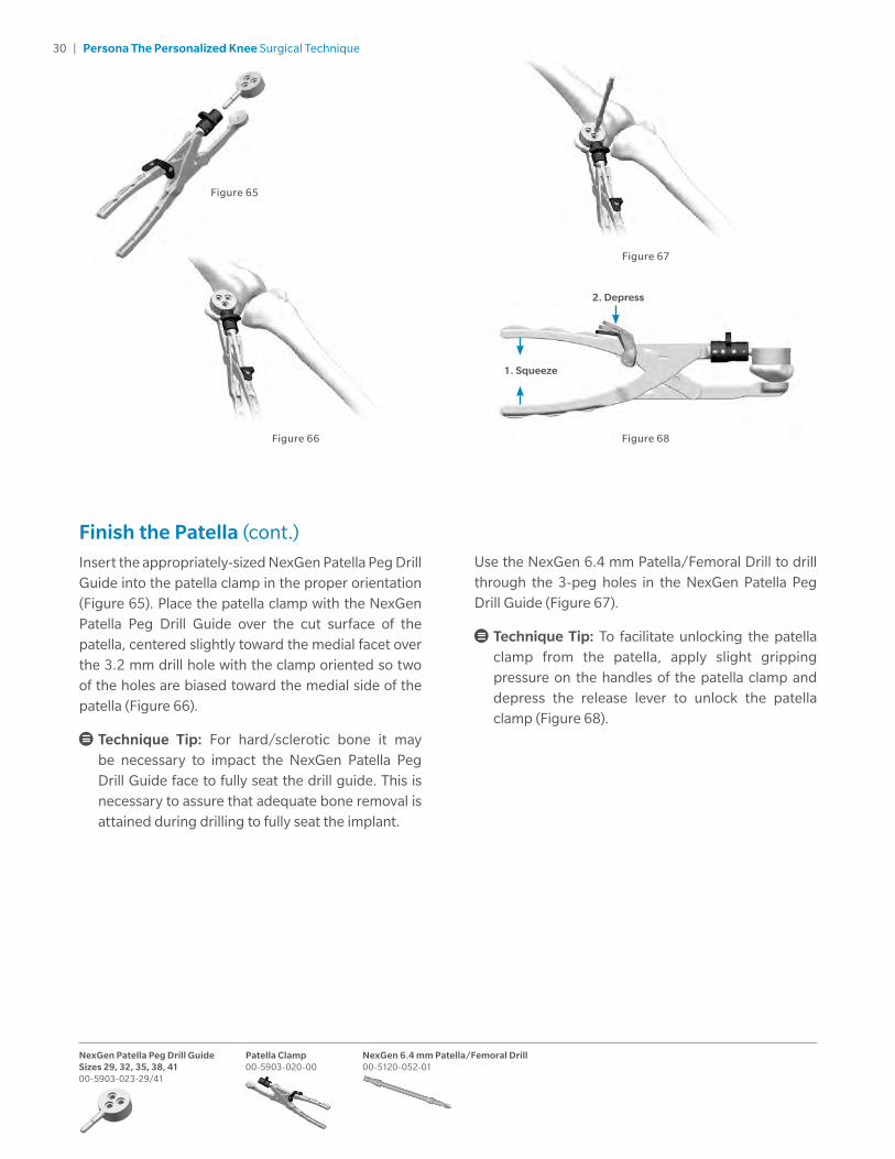
Insert the appropriately-sized NexGen Patella Peg Drill Guide into the patella clamp in the proper orientation (Figure 65). Place the patella clamp with the NexGen Patella Peg Drill Guide over the cut surface of the patella, centered slightly toward the medial facet over the 3.2 mm drill hole with the clamp oriented so two of the holes are biased toward the medial side of the patella (Figure 66).
Technique Tip: For hard/sclerotic bone it may be necessary to impact the NexGen Patella Peg Drill Guide face to fully seat the drill guide. This is necessary to assure that adequate bone removal is attained during drilling to fully seat the implant.
Figure 66 Figure 68
Figure 67
Figure 65
Use the NexGen 6.4 mm Patella/Femoral Drill to drill through the 3-peg holes in the NexGen Patella Peg Drill Guide (Figure 67).
Technique Tip: To facilitate unlocking the patella clamp from the patella, apply slight gripping pressure on the handles of the patella clamp and depress the release lever to unlock the patella clamp (Figure 68).

31 | Persona The Personalized Knee Surgical Technique
Persona Femoral Inserter/Extractor 42-5099-092-00
Persona Femoral CR Impactor Pad 42-5099-094-00
Persona CR Femoral Provisional Size 7 Right 42-5027-062-02
CR Femoral Finishing and Trialing
Technique Tip: Reference the orientation and size etched and/or engraved markings to identify the correct provisional.
Assemble the femoral CR impactor pad to the femoral inserter/extractor. Hold the femoral inserter/extractor with the handle in the open position and insert the femoral CR impactor pad, aligning the "CR" on the femoral CR impactor pad with the arrow on the femoral inserter/extractor (Figure 69a). The femoral CR impactor pad is keyed, so the femoral CR impactor pad may have to be rotated while placing and aligning the femoral CR impactor pad onto the femoral inserter/extractor.
Femoral sizes 3 through 11 are provided in two profiles, standard and narrow. The size 3 through 11 standard femoral provisionals have intermittent cutouts around the periphery, with the inner dimension representing the outer profile of the narrow femoral implant and the outer dimension representing the outer profile of the standard femoral implant (Figure 69b).
Figure 69a Figure 69b Figure 70
Femoral sizes 1 and 2 are provided in one profile, narrow; and femoral size 12 provided in one profile, standard. Thus the size 1, 2 and 12 femoral provisionals do not have intermittent cutouts. Care should be taken to use the appropriate standard or narrow implant as is related to side (left or right) and size based on the provisional fit and ROM provided during the trialing phase.
Technique Tip: Do not impact the anterior flange of the CR femoral provisional. Do not impact the medial or lateral aspects or the release lever of the femoral inserter/extractor.
Remove any posterior osteophytes or overhanging bone on the femur to facilitate maximum knee flexion. Attach the femoral inserter/extractor to the correct CR femoral provisional by inserting the hook on the femoral inserter/extractor arm into the anterior notch in the CR femoral provisional and close the handle on the femoral inserter/extractor to secure the CR femoral provisional (Figure 70).
Release Lever
Alignment Arrows
Narrow Cutouts

32 | Persona The Personalized Knee Surgical Technique
Persona Femoral Inserter/Extractor 42-5099-092-00
Persona Femoral CR Impactor Pad 42-5099-094-00
Persona CR Femoral Provisional Size 7 Right 42 5027-062-02
Pinch to release
Figure 71 Figure 73
Figure 72 Figure 74
CR Femoral Finishing and Trialing (cont.)Place the correct CR femoral provisional onto the femur in the desired medial/lateral position. Impact the end of the femoral inserter/extractor handle to fully seat the CR femoral provisional onto the femur (Figure 71). To remove the femoral inserter/extractor from the CR femoral provisional, pinch the release lever while pulling out/down (Figure 71). Alternatively, if the CR femoral provisional is placed on the femur by hand, the femoral inserter/extractor handle must be in the closed and locked position prior to engaging the CR femoral provisional. Then the femoral inserter/extractor can be used to impact the provisional onto the femur. For additional fixation of the fully seated provisional, insert the 25 mm x 3.2 mm screw (2.5 mm female hex) with the 2.5 mm male hex driver through the hole in the lateral anterior flange of the CR femoral provisional (Figure 72).
Technique Tip: Ensure the shoulder of drill is seated at bottom of the femoral provisional counterbore.
If the tibia has been prepared, a trial range of motion can be performed to assure proper positioning of the CR femoral provisional prior to femoral peg hole preparation. Once desired medial-lateral placement has been attained, drill the peg holes for size 3 through 12 femoral implants through the CR femoral provisional with the NexGen 6.4 mm Patella/Femoral Drill (Figure 73). For size 1 and 2 femoral implants use the NexGen 4.4 mm Femoral Peg Drill. If a screw was used to provide adjunct fixation, remove the screw from the anterior flange in the CR femoral provisional. The slaphammer can be used to remove size 3 through 12 CR femoral provisionals (Figure 74). Rotate the slaphammer a ¼ turn outward. For size 1 and 2 CR femoral provisionals the slaphammer can be inserted into the notch on the medial or lateral side of the provisional. Alternatively, the femoral inserter/extractor can be reattached to the CR femoral provisional to remove it from the bone. If necessary, place the round end of the slaphammer in the extraction hole of the femoral inserter/extractor to facilitate removal.
1. Insert
2. Rotate
3. Extract
25 mm x 2.5 mm Female Hex Screw 42-5099-025-25
NexGen 6.4 mm Patella/Femoral Drill 00-5120-052-01
Persona Slaphammer 42-5099-037-00
2.5 mm Male Hex Driver 42-5099-025-00
NexGen 4.4mm Femoral Drill for size 1 and 2 Femoral Provisionals 00-5965-009-00

33 | Persona The Personalized Knee Surgical Technique
Alignment Arrows
Release Lever
Figure 75a Figure 75b
CR Femoral Finishing and Trialing (cont.)
Technique Tip: Ensure oval hole of the femoral provisional is free of debris prior to inserting slaphammer.
Technique Tip: If trialing with TASP leave femoral provisional in place until trialing is complete.
Technique Tip: Do not impact the anterior flange of the CR femoral provisional for removal, as this may damage the CR femoral provisional.
PS Femoral Finishing and PS Box Preparation
Technique Tip: Reference the orientation and size etched and/or engraved markings to identify the correct provisional.
Assemble the femoral PS impactor pad to the femoral inserter/extractor. Hold the femoral inserter/extractor, with the handle in the open position and insert the femoral PS impactor pad, aligning the "PS" on the femoral PS impactor pad with the arrow on the femoral inserter/extractor (Figure 75a).
The femoral PS impactor pad is keyed, so the femoral PS impactor pad may have to be rotated while placing and aligning the femoral PS impactor pad onto the femoral inserter/extractor.
Femoral sizes 3 through 11 are provided in two profiles, standard and narrow. The size 3 through 11 standard femoral provisionals have intermittent cutouts around the periphery, with the inner dimension representing the outer profile of the narrow femoral implant and the outer dimension representing the outer profile of the standard femoral implant (Figure 75b). Femoral sizes 1 and 2 are provided in one profile, narrow; and femoral size 12 provided in one profile, standard. Thus the size 1, 2, and 12 femoral provisionals do not have intermittent cutouts. Care should be taken to use the appropriate standard or narrow implant as is related to side (left or right) and size based on the provisional fit and ROM provided during the trialing phase.
Persona Femoral Inserter/Extractor 42-5099-092-00
Persona Femoral PS Impactor Pad 42-5099-093-00
Persona PS-CPS Femoral Provisional Size 7 Right 42-5047-062-02

34 | Persona The Personalized Knee Surgical Technique
Persona Femoral Inserter/Extractor 42-5099-092-00
Persona Femoral PS Impactor Pad 42-5099-093-00
Persona PS-CPS Femoral Provisional Size 7 Right 42-5047-062-02
2.5 mm Male Hex Driver 42-5099-025-00
25 mm x 2.5 mm Female Hex Screw 42-5099-025-25
Persona PS Box Cut Guide 6-942-5099-060-03
Pinch to release
PS Femoral Finishing and PS Box Preparation (cont.)
Technique Tip: Do not impact the anterior flange of the PS femoral provisional. Do not impact the medial or lateral aspects or the release lever of the femoral inserter/extractor.
Remove any posterior osteophytes or overhanging bone on the femur to facilitate maximum knee flexion. Attach the femoral inserter/extractor to the correct PS femoral provisional by inserting the hook on the femoral inserter/extractor arm into the lateral notch in the PS femoral provisional and close the handle on the femoral inserter/extractor to secure the PS femoral provisional (Figure 76).
Place the correct PS femoral provisional onto the femur in the desired medial/lateral position. Impact the end of the femoral inserter/extractor handle to fully seat the PS femoral provisional onto the femur (Figure 77). To remove the femoral inserter/extractor from the PS femoral provisional, pinch the release lever while pulling out/down (Figure 77).
Alternatively, if the PS femoral provisional is placed on the femur by hand, the femoral inserter/extractor handle must be in the closed and locked position prior to engaging the PS femoral provisional. Then the femoral inserter/extractor can be used to impact the provisional onto the femur. For additional fixation of the fully seated PS femoral provisional, insert the 25 mm x 3.2 mm screw (2.5 mm female hex) with the 2.5 mm male hex driver through the hole in the lateral anterior flange of the PS femoral provisional (Figure 78a).
By hand, insert and hold the correct-sized PS box cut guide into the anterior holes of the PS femoral provisional (Figure 78b). For additional fixation of the fully seated PS box cut guide, insert the 25 mm x 3.2 mm screw (2.5 mm female hex) with the 2.5 mm male hex driver through one of the holes in the PS box cut guide. Separate PS box cut guides exist for the PS femoral provisional for sizes 1–2, 3–5, 6–9, and 10–12.
Figure 77
Figure 78a
Figure 78b
Figure 76

35 | Persona The Personalized Knee Surgical Technique
Persona PS-CPS Femoral Provisional Size 7 Right 42-5047-062-02
Persona PS Box Cut Guide 6-9 42-5099-060-03
2.5 mm Male Hex Driver 42-5099-025-00
25 mm x 2.5 mm Female Hex Screw 42-5099-025-25
PS Femoral Finishing and PS Box Preparation (cont.)
Technique Tip: Do not impact the PS box cut guide into the provisional.
Make the anterior to posterior PS box cut with a 1.27 mm (0.050 inch) thick, ½ inch wide oscillating or reciprocating saw blade, by resting the saw blade in a parallel manner on the front surface of the PS box cut guide. Avoid undercutting the medial and lateral condyles. This is particularly important for smaller femurs (Figure 79a).
Figure 79a Figure 79b
After completing the anterior-to-posterior box cut, make the vertical wall cuts for the PS notch cuts by resting the saw blade in a parallel manner against the interior sidewalls of the PS femoral provisional (Figure 79b).

36 | Persona The Personalized Knee Surgical Technique
2.5 mm Male Hex Driver 42-5099-025-00
25 mm x 2.5 mm Female Hex Screw 42-5099-025-25
Persona PS Box Cut Guide 6-9 42-5099-060-03
Persona PS-CPS Box Provisional Size 6-7 Right42-5047-007-12
PS Femoral Finishing and PS Box Preparation (cont.)
Technique Tip: Keep blades against the support features of the cut guide and femoral provisional to ensure adequate bone resection. The cut planes (A/P and vertical) extend below the top of the PS cam.
Technique Tip: Align the raised bumps on the exterior side walls of the box provisional with the grooves in the interior sidewalls of the femoral provisional.
If a screw was used to provide adjunct fixation, remove the screw and the PS box cut guide. By hand, insert the correct-sized PS box provisional into the PS femoral provisional to assure that adequate bone has been removed for the implant AND for proper patella trialing. Separate left and right PS box provisionals exist for sizes 1–2, 3–5, 6–9, and 10–12 PS femoral provisionals (Figure 80). The constrained posterior stabilized (CPS) cut slot must be used if a CPS bearing is selected. The CPS cut slot may also be used for PS box resections. Additional information for this product may be found in the Constrained Posterior Stabilized (CPS) Surgical Technique (97-5026-072-00).
Technique Tip: If the appropriately sized PS box provisionals does not easily seat into the PS femoral provisional, perform clean up cuts to assure adequate bone has been removed. Do NOT impact the PS box provisional. Make sure the PS femoral provisional is fully seated after inserting the correct PS box provisional.
Figure 80

37 | Persona The Personalized Knee Surgical Technique
NexGen 6.4 mm Patella/Femoral Drill 00-5120-052-01
2.5 mm Male Hex Driver 42-5099-025-00
25 mm x 2.5 mm Female Hex Screw 42-5099-025-25
Persona PS-CPS Box Provisional Size 6-7 Right 42-5047-007-12
Persona Slaphammer 42-5099-037-00
Persona PS-CPS Femoral Provisional Size 7 Right 42-5047-062-02
2. Insert
1. Remove
3. Rotate
4. Extract
PS Femoral Finishing and PS Box Preparation (cont.)
Technique Tip: Ensure the shoulder of drill is seated at bottom of the femoral provisional counterbore.
Drill the pegs holes for the size 3 through 12 femoral implants through the PS femoral provisionals with the NexGen 6.4 mm Patella/Femoral Drill (Figure 81). The size 1 and 2 femoral components do not have pegs thus drilling is not required for those sizes. Remove the screw from the anterior flange in the PS femoral provisional. Remove the PS box provisional. The slaphammer can be used to remove size 3 through 12 PS femoral provisionals (Figure 82). Rotate the slaphammer a ¼ turn outward. For size 1 and 2 PS femoral provisionals the slaphammer can be inserted into the notch on the medial or lateral side of the provisional. Alternatively, the femoral inserter/extractor can be re-attached to the PS femoral provisional to remove it from the bone. If necessary, insert the slaphammer in the extraction hole of the femoral inserter/extractor to facilitate removal.
Figure 81 Figure 82
Technique Tip: Ensure oval hole of the femoral provisional is free of debris prior to inserting slaphammer.
Technique Tip: If trialing with TASP leave femoral provisional in place until trialing is complete.
Technique Tip: Do not impact the anterior flange of the PS femoral provisional for removal, as this may damage the PS femoral provisional.

38 | Persona The Personalized Knee Surgical Technique
Perform Trial Reduction Remove any posterior osteophytes or overhanging bone on the femur to ensure maximum knee flexion. In this step, a trial reduction is performed to check component position, patellar tracking, range of motion (ROM), and joint stability. Depending on the order of the surgical steps, some of the provisional components may already be in place. For example if the cemented tibial sizing plate is to be used, it may already be in place. If the femoral provisional was the last bone preparation step, it will already be in place. If not, attach the femoral inserter/extractor to the appropriate femoral provisional and insert on the bone in the correct position (Figures 83a and 83b).
Technique Tip: Be sure that soft tissue is not trapped beneath the provisionals. Impact until fully seated.
Remove the femoral inserter/exactor from the provisional. With the knee in extension, ensure that the provisional is flush against the resected distal surface of the femur on the medial condyle. Retract the lateral side and check to make sure it is flush distally, on the lateral side. If preparation for patella resurfacing has been performed, insert the appropriate patella provisional during the trialing phase.
Figure 83a Figure 83b
Persona CR Femoral Provisional Size 7 Right 42-5027-062-02
Persona Femoral PS Impactor Pad 42-5099-093-00
Persona PS-CPS Box Provisional Size 6-7 Right 42-5047-007-12
Persona PS-CPS Femoral Provisional Size 7 Right 42-5047-062-02
Standard All-Poly Patella Provisional, Size 35 mm x 9 mm00-5971-065-35
Tibial Provisional Extractor 00-5977-017-00
Quick Connect Handle 00-5901-034-00
Tibial Impactor Head 00-5901-033-00
Persona Stemmed Tibial Provisional Size F Right 42-5321-075-02
Persona Femoral Inserter/Extractor 42-5099-092-00
Persona Cemented Tibial Sizing Plate Size F Right 42-5399-075-02
Persona Femoral CR Impactor Pad 42-5099-094-00

39 | Persona The Personalized Knee Surgical Technique
Figure 84a Figure 84b
Tibial Articular Surface Provisional (TASP) Assembly The TASP consists of three parts: a TASP bottom, a TASP shim, and a TASP top. Select the TASP bottom that matches the cemented tibial sizing plate or tibial baseplate implant. Select the TASP top that mates with both the TASP bottom and the femoral provisional or component as marked on the anterior face of the TASP top (Figure 84a). In addition to the markings on the parts, the same colors are used for the mating TASP tops and bottoms. Axially align the pin slots on the TASP top with the pins on the TASP bottom during assembly as these parts must be assembled BEFORE the TASP shim can be used (Figure 84b). Select the set of TASP shims that match the selected Tibial implant size.
Technique Tip: There are two TASP bottom thicknesses +0 mm and +6 mm. Use +0 mm bottom for 10–14 mm constructs and the +6 mm bottom for 16–20 mm constructs.
Note: TASP bottom pins are offset to prevent assembly of left TASP tops on right TASP bottoms and vice versa.
Technique Tip: As shown on the anterior face of the TASP top, confirm the correct constraint, femoral compatibility, tibial size, and side.
Technique Tip: Apply gentle manual pressure without impacting the TASP construct with either a mallet or hand. The TASP construct includes the TASP top, bottom, shim, and tibial sizing plate handle.
Technique Tip: As described on page 13, if using the cemented tibial sizing plate during the trialing phase, please assure that the necessary male-headed screws/pins are removed from the anterior surface of the cemented tibial sizing plate to avoid interference and potential damage to the TASP.
Pin Slots
Pins
Persona TASP Top Right CR 3-11/EF 42-5270-005-10
Persona TASP Top Right Medial Congruent 6-7/EF 42-5271-007-10
Persona TASP Top Right Ultracongruent 4-11/EF 42-5272-005-10
Persona TASP Top Right PS 6-9/EF 42-5274-007-10
Persona TASP Right EF +0 Bottom 42-5270-005-05
Persona TASP Right EF +6 Bottom 42-5270-005-15

40 | Persona The Personalized Knee Surgical Technique
Persona TASP Right EF +6 Bottom 42-5270-005-15
Persona TASP Top Right Ultracongruent 4-11/EF 42-5272-005-10
Persona TASP Top Right CR 3-11/EF 42-5270-005-10
Persona TASP Top Right Medial Congruent 6-7/EF 42-5271-007-10
Persona Tibial Sizing Plate Handle 42-5399-017-00
Persona TASP Shim EF 10 mm 42-5279-005-00
5-15 degrees
Tibial Articular Surface Provisional (TASP) Assembly (cont.)
The shims (10, 11, 12, 13, and 14 mm) are not side-specific. Attach the tibial sizing plate handle to the appropriate 10 mm shim (Figure 85a). While holding the TASP top and bottom together with one hand, lock the TASP top and bottom together by inserting the appropriate 10 mm shim with the tibial sizing plate handle (Figure 85b). The 10 mm shim will create a TASP construct which matches the thickness of the thinnest tibial bearing implant, 10 mm (Figures 86a and 86b).
Technique Tip: During assembly of the TASP construct, slide the shim in using a direct anterior approach between the TASP top and bottom. To avoid inadvertent separation, maintain slight pressure between the TASP top and bottom while inserting the shim.
The shims are incremented by 1 mm to create TASP constructs of 10 mm, 11 mm, 12 mm, 13 mm, or 14 mm to match the implant offering. The +6 mm bottoms are included for instances where the TASP construct needs to be 16 mm, 18 mm, or 20 mm. In these circumstances, the 10 mm, 12 mm, and 14 mm shims are to be used to create the respective TASP constructs.
Note: The maximum thickness of available CR implants is 18 mm. MC, UC, and PS implants are available in thicknesses up to 20 mm. Also, 15 mm, 17 mm, and 19 mm thicknesses are NOT available in CR, MC, UC, or PS.
It is recommended that the thinnest TASP construct (10 mm) be inserted into the joint space, with the knee at greater than 30 degrees of flexion (Figure 87a), to perform an initial ROM assessment.
If a thicker construct is needed to appropriately fill and balance the joint space, place the knee in approximately 5–15 degrees of flexion (Figure 87b) to facilitate in vivo removal and insertion of the shims with the tibial sizing plate handle.
Figure 85b Figure 86b
Figure 86a Figure 87a
Figure 87b
1. Depress
2. Insert3. Release
> 30 degrees
Figure 85a

41 | Persona The Personalized Knee Surgical Technique
Tibial Articular Surface Provisional (TASP) Assembly (cont.)
The entire TASP construct can be removed to exchange the shims of the TASP construct. This is accomplished by flexing the knee greater than 30 degrees, then lifting the tibial sizing plate handle while attached to the TASP construct. Once the anterior lip of the TASP bottom is above the anterior rail of the tibial sizing plate (Figure 87c), rotate the TASP out of the joint space medially or laterally (Figure 87d). This will aid in preventing unwanted shim disassembly during TASP removal.
Technique Tip: Varus/Valgus forces may make it difficult to remove the TASP construct. To aid in the removal of the TASP and prevent breakage, ensure that the joint is in a neutral position when removing the TASP construct.
As shown (Figure 88), size A and B tibias, size C and D tibias, size E and F tibias, and size G and H tibias, share side-specific tibial bottoms, tibial tops, and color, respectively.
When using the stemmed tibia provisional, assemble the stemmed tibia provisional to the tibial provisional extractor and insert in the prepared tibia bone. For additional fixation of the fully seated provisional, insert the 25 mm x 3.2 mm screw (2.5 mm female hex) with the 2.5 mm male hex driver through the two screw fixation holes in the medial and lateral compartments on the STP.
Note: Do NOT use 48 mm screws for cemented tibial sizing plate fixation. 48 mm screw are not recommended due to potential bone perforation.
Figure 87d
Figure 88
Figure 87c
Lift (>30 degrees) then rotate.
TASP Shim/Construct Thickness Anterior divots in the shim correspond to the overall construct thickness
as shown in the image above.
*Shared Sizing - A and B, C and D, E and F, G and H Cemented Tibial Sizing Plates have common TASP Tops, Bottoms and Shims respectively.
10 mm
11 mm
12 mm
13 mm
14 mm
Color Coded Side Specific Shared Sizing*
Tibial Sizing Plate No Yes No
Articular Surface Tops Yes Yes Yes
+0 Bottoms Yes Yes Yes
+6 Bottoms Yes Yes Yes
Shims No No Yes
Persona TASP Right EF +6 Bottom 42-5270-005-15
Persona TASP Top Right Ultracongruent 4-11/EF 42-5272-005-10
Persona TASP Top Right CR 3-11/EF 42-5270-005-10
Persona TASP Top Right Medial Congruent 6-7/EF 42-5271-007-10
Persona Tibial Sizing Plate Handle 42-5399-017-00
Persona TASP Shim EF 10 mm 42-5279-005-00
Persona Stemmed Tibial Provisional Size F Right 42-5321-075-02
Tibial Provisional Extractor 00-5977-017-00

42 | Persona The Personalized Knee Surgical Technique
Tibial Articular Surface Provisional (TASP) Assembly (cont.) Check ligament stability in extension and in 30 degrees, 60 degrees, and 90 degrees of flexion. Attempt to distract the joint in flexion to ensure that it will not distract. If a posterior stabilized component is used, hyperflex the knee and verify that the spine still engages the cam. Insert the patellar provisional onto the resected patellar surface. Perform a ROM to check patellar tracking. When component position, ROM, and joint stability have been confirmed, remove all provisional components.
If a CR femoral implant is to be used and the PCL is recessed or becomes deficient intraoperatively, the PCL should be fully resected and the Medial Congruent (MC) or ultracongruent (UC) TASP should be trialed to assure desired ROM and joint stability prior to bearing implant selection.
When trialing with either a CR or MC insert and the PCL is retained, posterior soft tissue tightness may occur, resulting in the femur booking open (Figure 89). Should this occur, consider resecting the PCL. If the PCL is resected, either a MC or UC bearing should be used.
If unacceptable flexion/extension gap imbalances exist, refer to the "Balance Flexion/Extension Gaps" section of Appendix B for potential options.
The constrained posterior stabilized (CPS) TASP may also be assessed if further stability is needed. Additional information for this product may be found in the Constrained Posterior Stabilized (CPS) Surgical Technique (97-5026-072-00). When greater varus/valgus constraint is needed and/or stems or augments are required, the surgeon should consider using a revision implant system.
Assemble the tibial provisional extractor to the stemmed tibia provisional to remove the stemmed tibia provisional prior to implanting the components.
Technique Tip: If the TASP construct is used with the femoral and/or tibial implants, contact with bone cement should be avoided to prevent potential damage to the TASP components.
Technique Tip: The articular surface inserter should not be used with the TASP.
Technique Tip: Use only the tibial sizing plate handle to remove the TASP construct. The use of other instruments may damage or break the TASP.
Figure 89
Consider resecting the PCL if the femur appears to book open.
Persona Tibial Sizing Plate Handle 42-5399-017-00

43 | Persona The Personalized Knee Surgical Technique
Standard All-Poly Patella Provisional, Size 35 mm x 9 mm 00-5971-065-35
Quick Connect Handle 00-5901-034-00
Tibial Impactor Head 00-5901-033-00
Persona Cemented Stemmed Tibial Plate Sizes F Right 42-5320-075-02
Implant Components
Technique Tip: Prior to cementing implants remove provisionals and use pulse lavage to remove unwanted debris from the resected bone surfaces and the joint space.
In this step, the final components are implanted, and the tibial bearing is secured to the implanted tibial baseplate. When using cemented components, it is recommended to use two batches of cement. After the implants have been chosen, make a final check to ensure that all components are compatible. If the resected surfaces of the tibia and/or femur are sclerotic, drill multiple holes with a small drill (2.0 mm–3.2 mm) to improve cement intrusion. Mix the cement following the manufacturer's guidelines for cement prep including but not limited to mix, work, and set time.
Tibial Plate
Sublux the tibia anteriorly to allow adequate clearance to insert the tibial implant into the prepared bone. Do not apply substances other than bone cement to the tibial implant (i.e. do not dip implant into antibiotics or other substances). Keep the implant clean and free of debris prior to cementing. Place a layer of cement on the underside of the tibial baseplate, around the keel, on the resected tibial surface, and in the tibial IM canal. Assemble the quick connect handle to the tibial impactor head (Figure 90). Unlock collar and hold, insert handle into impactor head, release collar, and rotate handle until “click” is heard. Refer to the option of an attached inserter for the tibial plate insertion, located in Appedix C. Position the tibial plate onto the tibia and use the tibial impactor to impact it until fully seated (Figure 91). Thoroughly remove any excess cement in a consistent manner. Allow the cement to fully cure before performing a trial ROM or inserting the bearing.
Figure 90 Figure 91
1. Unlock Collar
2. Insert
3. Release
4. Rotate

44 | Persona The Personalized Knee Surgical Technique
Persona FemoralInserter/Extractor 42-5099-092-00
Persona Femoral PS Impactor Pad 42-5099-093-00
Persona Femoral CR Impactor Pad 42-5099-094-00
Persona CR Femoral Component Size 7 Right 42-5026-062-02
Persona PS Femoral Component Size 7 Right 42-5006-062-02
Femoral Impactor Head 00-5901-032-00
Tibial Impactor Head 00-5901-033-00
Quick Connect Handle 00-5901-034-00
Implant Components (cont.)Femoral Component
With the knee in 70 degrees – 90 degrees of flexion, retract the soft tissue in the desired manner. Place a layer of cement on the underside of the prosthesis and in the holes drilled in the femur. Attach the femoral inserter/extractor to the femoral component (Figures 92a and 92b). Insert the femoral component onto the distal femur by translating the component laterally until the lateral peg aligns with the drill hole in the lateral femoral condyle. Take care to avoid scratching the implant component surfaces. After the femoral component is placed on the femur and the femoral inserter/extractor is removed, the femoral inserter/extractor can be used to fully seat the implant onto the femur. If this method is used,the femoral inserter/extractor handle must be in the closed and locked position. Ensure that soft tissue is not trapped beneath the implant. Alternatively, assemble the quick connect handle to the femoral impactor head (Figure 93). Use this assembly to fully seat the femoral implant (Figure 94). Remove retractors, and check the medial and lateral sides to make sure the femoral implant is fully impacted distally. Remove any excess cement in a thorough and consistent manner.
Bearing
The articular surface inserter applies both downward and rearward forces to aid in the insertion of the bearing onto the tibial base plate. Choose the correct tibial bearing based on size, side, constraint and thickness as determined by the trial range of motion. Place the bearing onto the tibial base plate. Apply pressure anterior to posterior to properly engage the tibial component and tibial bearing for final seating. This is necessary to allow the inserter to properly engage the tibial component and tibial bearing for final seating (Figure 95). Steady the surface of the base plate with one hand by applying downward pressure near the posterior cruciate cutout.
Technique Tip: Insert a bearing only once. Never reinsert the same bearing onto a tibial base plate.
Figure 94
Figure 95Figure 93
1. Unlock Collar
2. Insert
3. Release
4. Rotate
1.2.
Figure 92a
Figure 92b

45 | Persona The Personalized Knee Surgical Technique
Persona UC Tibial Articular Component Size 4-11/EF Right 42-5212-005-10
Persona PS Tibial Articular Component Size 6-9/EF Right 42-5214-007-10
Persona Articular Surface Inserter 42-5299-001-00
Articular Surface Removal Instrument 00-5977-021-00
Persona Stemmed Cemented Tibial Component Size F Right 42-5320-075-02
Persona CR Tibial Articular Component Size 3-11/EF Right 42-5210-005-10
Persona MC TibialArticular Component 6-7/EF Right 42-5221-007-10
Implant Components (cont.)Bearing (cont.)
Engage the hook on the articular surface inserter with the mating slot in the front of the base plate and close the lever with your index finger. This locks the inserter to the tibial plate (Figure 96a). Squeeze the handle of the articular surface inserter to seat the bearing (Figure 96b). Open the lever and remove the articular surface inserter.
Alternatively the bearing can be locked into the tibial plate as described above, prior to tibial plate implantation. If PS femoral implants are used, the femoral implant should be implanted before the tibial implant to avoid the excessive joint distraction required to clear the post while implanting the PS femoral implant. If CR femoral implants are used, the tibial implant should be implanted prior to the femoral implant to facilitate the removal of excess cement from the posterior aspect of the tibia, prior to femoral implantation.
Figure 96b Figure 97Figure 96a
Technique Tip: Only in vivo assembly of the ultracongruent bearing is recommended because the design of the ultracongruent bearing precludes cement removal from the PCL cutout area at the tibial baseplate/bone interface.
Assemble the quick connect handle to the tibial impactor head. Unlock collar and hold, insert quick connect handle into tibial impactor head, release collar, and rotate handle until “click” is heard. Position the tibial plate bearing construct onto the tibia and use the tibial impactor to impact it until fully seated (Figure 97). Thoroughly remove any excess cement in a consistent manner.
Technique Tip: Do NOT impact or lever the articular surface inserter or extractor tools when they are attached to the tibial plate as this may disrupt the fixation of the tibial plate to the bone and/or cause damage to the implant or instrument. Also, do not impact the bearing.
To remove a bearing from the baseplate, engage the hook on the articular surface removal instrument with the mating slot on the front of the baseplate and squeeze the handle to disengage the bearing from the base plate. The articular surface removal instrument should not be used for provisional removal.

46 | Persona The Personalized Knee Surgical Technique
Patella Clamp 00-5903-020-00
Patella Clamp Head 00-5903-021-00
Persona All-poly Patella Size 32 mm 42-5400-000-32
Implant Components (cont.)Patellar Component
Please refer to the appropriate surgical technique if other patella instrumentation is to be used to accomplish the patella implantation.
All-Polyethylene Patella
With the knee in 70 degrees – 90 degrees of flexion, apply cement to the anterior surface and pegs of the patellar component while in a doughy consistency. Alternatively, this step can be performed with the knee in full extension. Locate the drilled peg holes and use the patella clamp assembly to insert and secure the patella in place. Fully open the jaws of the patella clamp and align the tooth to the anterior surface of the patella and the patella clamp head to the posterior surface of the implant (Figure 98). Use the patella clamp to apply enough pressure to fully seat the implant on the patellar surface. Remove any excess cement in a thorough and consistent manner.
Figure 98
Close IncisionFreely irrigate the wound with the solution of choice to assure unwanted debris is removed from the joint space prior to closure. A drain may be placed intracapsularly. Then close the wound with sutures and apply a bandage. Please refer to package insert for complete product information, including contraindications, warnings, precautions, and adverse effects.
Surgeon Notes and Tips
Take care that the retractors do not inadvertently dislodge the tibial baseplate, particularly on the posterolateral corner. Verify that the femoral component is fully seated before closing the wound. Confirm that no portion of the quadriceps mechanism has been pinned beneath the femoral component.

47 | Persona The Personalized Knee Surgical Technique
Pin/Screw Inserter 00-5901-021-00
Persona Drop Rod Adapter 42-5399-006-00
Persona Tibial Cut Guide Right - 7° 42-5399-052-07
75 mm x 3.2 mm Trocar Tipped Drill Pin (2.5 mm hex) 00-5901-020-00
Alignment Rod with Coupler 00-5785-080-00
2° Valgus Recut Guide 00-5901-090-00
NexGen PRI Alignment Adapter 00-5901-086-00
Appendix A
2 Degrees Valgus Recut GuideInsert the Persona Drop Rod Adapter into the tibial cut guide. Place the alignment rod with coupler into the drop rod adaptor and assess the cut (Figure 99).
If a valgus correction cut is needed, place the valgus recut guide on the resected tibial plateau by attaching the alignment rod with coupler and the NexGen PRI Alignment Adaptor. Align with the medial 1/3 of the tubercle. Once it has been determined that the desired correction cut will be attained, slide the medial portion of the valgus recut guide so it is flush with the medial portion of the tibial cortex to provide a planar recut of the tibia. Affix with 3.2 mm trocar tipped pins using the pin and screw inserter.
Technique Tip: The fixation holes for the valgus recut guide are at oblique angles to improve fixation of the guide.
Perform resection, remove trocar tipped pins, and the valgus recut guide (Figure 100).
Valgus Recut Needed
Figure 99 Figure 100
Correction Resection

48 | Persona The Personalized Knee Surgical Technique
Pin/Screw Inserter 00-5901-021-00
Persona Drop Rod Adapter 42-5399-006-00
Persona Tibial Cut Guide Right - 7° 42-5399-052-07
75 mm x 3.2 mm Trocar Tipped Drill Pin (2.5 mm hex) 00-5901-020-00
Alignment Rod with Coupler 00-5785-080-00
2° Valgus Recut Guide 00-5901-090-00
NexGen PRI Alignment Adapter 00-5901-086-00
1SECTION
39
APPENDIX
A Establish the Tibial PlatformVarus/Valgus Recut Guides
2° Varus Recut GuideInsert the Alignment Adapter into the tibial cut guide. Place the Alignment Rod with Coupler into the alignment adapter and assess the cut. (Fig. 100) If a varus correction cut is needed, place the 2° Varus Recut Guide on the resected tibial plateau and affix with 3.2mm trocar-tipped pins with the Pin and Screw Inserter.
Insert the alignment adapter into the recut guide. Place the alignment rod into the alignment adapter and verify the desired alignment. (Fig. 101) Remove the alignment adapter and alignment rods, perform resection, remove the trocar-tipped pins and the guide.
TECHNIQUE TIP A.2
The fixation holes for the recut guide are at oblique angles to improve fixation of the guide.
Instruments
Alignment Rod with Coupler
00-5785-080-00
Tibial Cut Guide, 7°, Left
00-5901-077-00
Tibial Cut Guide, 7°, Right
00-5901-078-00
Tibial Cut Guide, 7°, Universal
00-5901-080-00
Tibial Cut Guide, 0°, Left
00-5901-075-00
Tibial Cut Guide, 0°, Right
00-5901-076-00
Tibial Cut Guide, 0°, Standard
00-5901-079-00
Pin/Screw Inserter 00-5901-021-00
Multi Pin Puller00-5901-022-00
3.2mm x 75mm Trocar Tipped
Drill Pin (2.5 hex) 00-5901-020-00
Alignment Adapter00-5901-086-00
2° Varus Recut Guide
00-5901-090-01
Fig. 100 Fig. 101
Varus Recut Needed
Correction Resection
Varus Recut Needed
Appendix A (cont.)
2 Degrees Varus Recut GuideInsert the Persona Drop Rod Adapter into the tibial cut guide. Place the alignment rod with coupler into the drop rod adaptor and assess the cut (Figure 101).
If a varus correction cut is needed, place the varus recut guide on the resected tibial plateau by attaching the alignment rod with coupler and the NexGen PRI Alignment Adaptor. Align with the medial 1/3 of the tubercle. Once it has been determined that the desired correction cut will be attained, slide the lateral portion of the varus recut guide so it is flush with the lateral portion of the tibial cortex to provide a planar recut of the tibia. Affix with 3.2 mm trocar tipped pins using the pin and screw inserter.
Figure 101 Figure 102
Technique Tip: The fixation holes for the varus recut guide are at oblique angles to improve fixation of the guide.
Perform resection, remove trocar tipped pins, and the varus recut guide (Figure 102).
1SECTION
39
APPENDIX
A Establish the Tibial PlatformVarus/Valgus Recut Guides
2° Varus Recut GuideInsert the Alignment Adapter into the tibial cut guide. Place the Alignment Rod with Coupler into the alignment adapter and assess the cut. (Fig. 100) If a varus correction cut is needed, place the 2° Varus Recut Guide on the resected tibial plateau and affix with 3.2mm trocar-tipped pins with the Pin and Screw Inserter.
Insert the alignment adapter into the recut guide. Place the alignment rod into the alignment adapter and verify the desired alignment. (Fig. 101) Remove the alignment adapter and alignment rods, perform resection, remove the trocar-tipped pins and the guide.
TECHNIQUE TIP A.2
The fixation holes for the recut guide are at oblique angles to improve fixation of the guide.
Instruments
Alignment Rod with Coupler
00-5785-080-00
Tibial Cut Guide, 7°, Left
00-5901-077-00
Tibial Cut Guide, 7°, Right
00-5901-078-00
Tibial Cut Guide, 7°, Universal
00-5901-080-00
Tibial Cut Guide, 0°, Left
00-5901-075-00
Tibial Cut Guide, 0°, Right
00-5901-076-00
Tibial Cut Guide, 0°, Standard
00-5901-079-00
Pin/Screw Inserter 00-5901-021-00
Multi Pin Puller00-5901-022-00
3.2mm x 75mm Trocar Tipped
Drill Pin (2.5 hex) 00-5901-020-00
Alignment Adapter00-5901-086-00
2° Varus Recut Guide
00-5901-090-01
Fig. 100 Fig. 101
Varus Recut Needed
Correction Resection
Correction Resection

49 | Persona The Personalized Knee Surgical Technique
Spacer Block Technique
Technique Tip: The distal thickness of the Persona CR and PS Femoral Components is 9 mm for sizes 3-12 and 8 mm for sizes 1-2. The posterior thickness of the Persona CR Component is 9 mm for sizes 3-12 and 8 mm for sizes 1-2. The posterior thickness of the Persona PS Component is 10 mm for sizes 3-12 and 9 mm for sizes 1-2.
Note: The spacer block techniques described below only apply when the femoral bone cuts have been made for a size 3-12 femur. If the femoral bone cuts have been made for a size 1-2 femur, adjust the technique to account for the distal femoral thickness difference described above.
Check Extension Gap
After the proximal tibia and distal femur have been resected, the extension gap can be evaluated using spacer blocks or a tensioning device. Position the knee in full extension. The distal thickness of the Persona Femoral Component is 9 mm and the minimum Persona Tibial Articular Surface/Baseplate Construct is 10 mm. If a 10 spacer block (19 mm thickness) does not fit into the resected joint space in extension, it will be necessary to remove additional bone from either the tibia or the femur. The spacer block physical thicknesses are 9 mm more than what are shown on the spacer blocks to represent the combined Persona distal femoral thickness and the corresponding tibial component thickness.
Use the spacer/alignment guides or MIS spacer/alignment guides to check the extension gap. Insert the thinnest appropriate spacer/alignment guide between the resected surfaces of the femur and tibia (Figure 103). If necessary, insert progressively thicker spacer/alignment guides until the desired soft tissue tension is obtained. Drop the alignment rod with coupler into the spacer/alignment guide. Check the flatness, slope and alignment of the tibial cut. Apply varus and valgus stress for optimal ligament balancing. Ligament releases should be performed until the extension gap is rectangular. When the extension gap is balanced, proceed to size femur, establish external rotation, and finish the femoral cuts.
Check Flexion Gap
After the femoral finishing cuts have been completed and with the knee in 90 degrees flexion, use the spacer/alignment guides or MIS spacer/alignment guides to check ligament balance and joint alignment in flexion. Insert the alignment rod with coupler into the guide and check the alignment of the tibial resection (Figure 104). Then check ligament balance. If necessary, insert progressively thicker spacer blocks until the desired soft tissue tension is obtained.
Figure 103 Figure 104
Appendix B

50 | Persona The Personalized Knee Surgical Technique
Alignment Rod with Coupler 00-5785-080-00
Alignment Rod 00-5785-079-00
MIS Spacer/Alignment Guide 00-5983-070-10
Spacer Block Technique (cont.)Balance Flexion and Extension Gaps
Technique Tip: Prior to addressing flexion/extension imbalances, make sure that desired varus/valgus alignment has been attained.
Technique Tip: If femoral or tibial recuts are performed subsequent femoral finishing and tibial finishing steps need to be repeated to provide for proper provisional and component fit.
With the knee in extension, attach the alignment rod to the alignment rod with coupler. Check ligament balance and limb alignment in extension. Refer to Figure 105 for potential solutions for flexion/extension mismatches.
1. If a knee is too tight in both flexion and extension, resecting additional tibial bone or reducing the height of the tibial bearing may be sufficient to balance the construct.
Figure 105
2. If the knee is tight in flexion but acceptable in extension, three options exist. One option is to release the PCL either by island osteotomy or ligament release, both of which lengthen the ligament. If the PCL is absent, change constraint to MC or UC. A second option is to cement the femoral component distal to the bone cut. This augmentation with cement distally fills the extension space when used with a thinner tibial bearing. The third option is to downsize the femoral component.
3. If the joint is loose in extension and tight in flexion one option is to use a smaller sized femoral component possibly with a thicker polyethylene component.
4. If the joint is acceptable in flexion but tight in extension, several options exist. One is to release the posterior capsule from the femur. Another alternative is to resect more distal femoral bone. This moves the femoral component proximally on the femur at the expense of elevating the joint line.
Appendix B (cont.)
Extension
Flexion Tight OK Loose
Tight 1 2 3
OK 4 5 6
Loose 7 8 9

51 | Persona The Personalized Knee Surgical Technique
Spacer Block Technique (cont.)Balance Flexion and Extension Gaps (cont.)
5. If both components are acceptable, no further modification is necessary.
6. If the joint is acceptable in flexion and loose in extension, consider downsizing the femoral component with a thicker tibial bearing. If the femoral component cannot be downsized, cement the femoral component distal to the bone cut. This augmentation with cement distally fills the extension space.
7. If the joint is loose in flexion and tight in extension, a larger femoral component may suffice. A second option is a thicker tibial bearing with a more proximal femoral position. A third option is a thicker tibial component combined with a posterior release.
8. If the joint is loose in flexion and acceptable in extension, increasing the femoral size may equalize the gaps. Alternatively, moving the femoral component proximally and applying a thicker tibial bearing will equalize the gaps. Another option is to fill the flexion gap with the appropriate poly and perform a posterior release to increase the extension gap.
9. If a joint is symmetrically loose in both flexion and extension, a thicker tibial bearing will usually solve both problems.
In situations where two options exist to help solve the soft tissue mismatch, the position of the patella or the joint line helps the surgeon decide which option to select.
Note: After applying one of these solutions, perform another trial reduction. This will identify any new problem or a variation of the initial problem that may exist.
Figure 106
Appendix B (cont.)
Extension
Flexion Tight OK Loose
Tight 1 2 3
OK 4 5 6
Loose 7 8 9

52 | Persona The Personalized Knee Surgical Technique
Persona 8 mm IM Rod 42-5099-002-00
Persona Modular Handle 42-5099-014-00
Persona 5° Valgus Alignment Guide 42-5099-005-05
Persona 9 mm Distal Resection Plate 42-5099-015-09
1. Pull
2. Insert
Resect Distal Femur – Fixed Distal Resection InstrumentAssemble Fixed Distal Resection Instrumentation
Pull the lever on the modular handle and insert the IM rod (Figure 107). Orientation of the IM rod will align with the polished line on the sides of the modular handle.
Technique Tip: Alternately, the IM rod may be inserted into the top of the modular handle to accommodate surgical preference.
Insert the IM rod into the fixed valgus guide.
Note: If desired, align the depth markings on the IM rod with the flat plate of the fixed valgus guide to set the IM rod at a specific length (Figure 108).
Figure 107
Insert the fixed resection tower into the face of the fixed valgus guide indicating the angle and side of the knee (left or right).
Note: The valgus alignment guide will resect 10 mm of distal bone. The distal resection can be changed to 1 mm through 9 mm resection depth, in 1 mm increments, by assembling the corresponding resection plate to the valgus guide. Figure 109 illustrates this with the 9 mm resection plate. The 9 mm and 8 mm resection plates may facilitate correction of recurvatum and the 1 mm – 3 mm resection plates can be used for recutting the distal femur, if needed.
The size 1 and 2 femoral components are 1 mm thinner distally than sizes 3-12. Consider adjusting the resection depth on these sizes to accommodate for this difference.
Appendix C: Optional Instruments
Figure 109
Figure 108

53 | Persona The Personalized Knee Surgical Technique
Persona 8 mm IM Rod 42-5099-002-00
Persona Modular Handle 42-5099-014-00
Persona 5° Valgus Alignment Guide 42-5099-005-05
Persona Fixed Resection Tower 42-5099-006-00
Persona 0° Distal Cut Guide 42-5099-010-00
Resect Distal Femur – Fixed Distal Resection Instrument (cont.)Assemble Fixed Distal Resection Instrumentation (cont.)
Rotate the lock lever on the fixed resection tower to the unlocked, or “in-line”, position and fully insert into the cut guide (Figure 110a).
Appendix C: Optional Instruments (cont.)
Figure 110a Figure 110b
Flip the lock lever to the locked, or “vertical”, position to secure it to the cut guide (Figure 110b).
Technique Tip: The fixed resection tower is compatible with the adjustable valgus guide and the adjustable resection tower is compatible with the fixed valgus guide. These instruments can be interchanged to accommodate surgical preference.
2. Insert 1. Unlock
Lock

54 | Persona The Personalized Knee Surgical Technique
8 mm IM Step Drill 00-5978-014-00
Persona 8 mm IM Rod 42-5099-002-00
Persona Modular Handle 42-5099-014-00
Persona 5° Valgus Alignment Guide 42-5099-005-05
Persona Fixed Resection Tower 42-5099-006-00
Persona 0° Distal Cut Guide 42-5099-010-00
Resect Distal Femur – Fixed Distal Resection Instrument (cont.)Establish Femoral Alignment
Drill the IM canal using the 8 mm IM step drill (Figure 111). Suction the canal to remove medullary contents.
Insert the IM rod and assembled distal resection instrumentation into the IM canal far enough to ensure the most accurate replication of the anatomic axis.
Set the orientation of the fixed valgus guide by placing it against the most prominent distal condyle and rotating it about the IM rod so that it is aligned with the epicondylar axis (Figure 112).
Appendix C: Optional Instruments (cont.)
Figure 111 Figure 112 Figure 113
Note: Setting rotation of the fixed valgus guide is important for creating a distal resection that matches the desired valgus angle selected. It does not set the rotation of the femoral component.
To secure orientation, impact the captured pin on the medial side of the fixed valgus guide until the head of the captured pin is flush with the plate (Figure 113).

55 | Persona The Personalized Knee Surgical Technique
Persona Drop Rod Adapter 42-5399-006-00
Alignment Rod with Coupler 00-5785-080-00
3.2 mm x 75 mm Trocar Tipped Drill Pin (2.5 mm hex) 00-5901-020-00
Pin/Screw Inserter 00-5901-021-00
Persona 8 mm IM Rod 42-5099-002-00
Persona Modular Handle 42-5099-014-00
Persona 5° Valgus Alignment Guide 42-5099-005-05
Persona Fixed Resection Tower 42-5099-006-00
Persona 0° Distal Cut Guide 42-5099-010-00
1. Unlock
2. Pull
Resect Distal Femur – Fixed Distal Resection Instrument (cont.)Resect Distal Femur
Verify the fixed valgus guide is set to the proper side (left or right) and the fixed valgus guide shows the appropriate valgus angle.
Technique Tip: Confirm valgus alignment by inserting the drop rod adapter into the large holes on the anterior face of the cut guide and insert an alignment rod into the drop rod adapter (Figure 114).
Insert a trocar tipped pin through each of the standard pin holes marked ‘0’ on the anterior surface of the cut guide (Figure 115).
Flip the lock lever on the fixed resection tower to the unlocked, or “in-line”, position and pull the handle to remove the IM rod and assembled distal resection instrumentation leaving only the cut guide attached to the femur (Figure 116).
Figure 114 Figure 115 Figure 116
Note: If the captured pin was deployed it may be necessary to first remove it from the bone using the pin puller. Alternatively, removing the IM rod from the fixed valgus guide may facilitate removal of the captured pin from the bone.
Technique Tip: Additional 2 mm adjustments may be made by using the sets of holes marked -2, +2, and +4. These sets of holes indicate, in millimeters, the amount of additional bone resection each will yield relative to the 10 mm resection accommodated by the fixed resection tower (however, if the 9 mm resection plate is used, the depth adjustments are relative to a 9 mm resection).
Appendix C: Optional Instruments (cont.)

56 | Persona The Personalized Knee Surgical Technique
Persona Anterior Referencing Sizer 42-5099-088-00
2.5 mm Male Hex Driver 42-5099-025-00
Size Femur – Anterior Referencing SizerSize Femur and Establish External Rotation
Rotate the feet of the anterior referencing sizer so the appropriate “left” or “right” markings are visible as the anterior referencing sizer is placed on the bone (Figure 117). External rotation can be set at 3 degrees or 5 degrees from the posterior condylar axis.
Technique Tip: Remove any osteophytes that interfere with instrument positioning.
Apply the anterior referencing sizer so that the flat surface of the anterior referencing sizer is flush against the resected surface of the distal femur and the feet of the anterior referencing sizer are flush against the posterior condyles. Center the anterior referencing sizer mediolaterally. Both the vertical and horizontal portions of the anterior referencing sizer provide visual cues relative to the AP and epicondylar axes of the femur to help ensure that desired external rotation is attained.
Figure 117 Figure 118
Note: Sizer geometry is rotated 3 degrees to align to the A/P and epicondylar axes of the femur. The 3 degrees drill holes are rotated 3 degrees from the posterior feet and are neutral to the central sizer geometry. This enables use of the A/P and epicondylar axis to set rotation.
If the 3 degrees external rotation holes are to be used to set external rotation, the etched line on the anterior referencing sizer should be positioned so it is in line with Whiteside’s line (Figure 118) to optimize the M/L position of the drill holes for subsequent anterior referencing 4-in-1 cut guide placement.
Appendix C: Optional Instruments (cont.)
Side Designation

57 | Persona The Personalized Knee Surgical Technique
Size Femur – Anterior Referencing Sizer (cont.)Size Femur and Establish External Rotation (cont.)
If the 5 degrees external rotation holes are to be used, the sizer can be positioned with the etched line on the anterior referencing sizer 4 mm laterally from Whiteside’s line to better center the drill holes for subsequent anterior referencing 4-in-1 cut guide placement, due to the M/L offset of the holes. Hold the anterior referencing sizer in place and if necessary, secure the anterior referencing sizer to the femur using 25 mm x 3.2 mm (2.5 mm female hex) screws (Figure 119) in one or both of the holes on the lower portion of the anterior referencing sizer to help draw the anterior referencing sizer adjacent to the distal femur, particularly in MIS situations.
Note: Do NOT use 48 mm screws for fixation of the anterior reference sizer. 48 mm screws are not recommended due to potential bone perforation.
Figure 119
Slightly extend the knee and retract soft tissues to expose the anterior femoral cortex. Clear any soft tissue from the anterior cortex. Ensure that the leg is in less than 90 degrees of flexion (70 degrees – 80 degrees). This will decrease the tension of the patellar tendon to facilitate placement of the anterior referencing sizer boom. The position of the anterior referencing sizer boom tip approximates the proximal position of the anterior flange of the femoral component. The anterior referencing sizer boom can be rotated to facilitate insertion under the soft tissue envelope. A palpable indication as well as a vertical orientation of the end of the anterior referencing sizer boom (Figure 122) ensures that the anterior referencing sizer boom is rotated to the correct position.
Technique Tip: Do not impact the anterior referencing sizer onto the femur.
Appendix C: Optional Instruments (cont.)
Persona Anterior Referencing Sizer 42-5099-088-00
2.5 mm Male Hex Driver 42-5099-025-00

58 | Persona The Personalized Knee Surgical Technique
Size Femur – Anterior Referencing Sizer (cont.)Size Femur and Establish External Rotation (cont.)
Technique Tip: Positioning the anterior referencing sizer boom tip on the “high” part of the femur by lateralizing the location of the anterior referencing sizer boom tip can often lessen the likelihood of notching the femur.
After the anterior referencing sizer boom is appropriately positioned, read the femoral size from the engraved lines on the anterior referencing sizer tower and select the closest size (Figure 120). There are six even sizes labeled on the left side of the tower and six odd sizes labeled on the right side of the tower, with lines indicating the in-between sizes. The same size markings are present on the anterior surface of the anterior referencing sizer boom and approximate the proximal position of the anterior flange of the femoral component when telescoped to the same size that has been determined by the vertical anterior referencing sizer tower (Figure 121). The 3 degrees or 5 degrees holes in the midline of the A/P portion of the anterior referencing sizer are used to drill 3.2 mm holes for pegs on the anterior referencing 4-in-1 femoral cut guide (Figure 122).
Figure 120
Figure 121
Figure 122
A 3.2 mm pin may be placed in the first drilled hole to maintain an “index” position prior to drilling the second hole. Remove the screws, then remove the anterior referencing sizer.
Technique Tip: The multi pin puller cannot be used to extract the screw(s).
Technique Tip: This anterior referencing sizer works only with these anterior referencing 4-in-1 femoral cut guides and provisionals, and implants referenced in this technique.
25 mm x 2.5 mm Female Hex Screw 42-5099-025-25
3.2 mm Drill 00-5120-085-00
Appendix C: Optional Instruments (cont.)

59 | Persona The Personalized Knee Surgical Technique
Persona Shift Block 42-5099-085-10
3.2 mm Drill 00-5120-085-00
Shift BlockPrior to performing the four facet cuts with the 4-in-1 cut guide, determine whether the position of the block anterior to posterior and external rotation is sufficient. If adjustment is needed, remove the 4-in-1 cut guide from the femur and insert the shift block using the same holes in the distal face of the femur (Figure 123).
To select the method of adjustment, depress button and rotate drill guide until the desired face is shown. If a 2 degrees rotation is desired, rotate the guide to the appropriate 2 degrees rotation face (Figure 124).
If an A/P shift is desired, rotate the guide to the appropriate 1 mm shift face (Figure 125).
Figure 123 Figure 125
Figure 124
Technique Tip: The Persona Shift Block is only to be used with the Persona 4-in-1 Cut Guides.
Technique Tip: Do not impact or torque the shift block while inserting or drilling.
Appendix C: Optional Instruments (cont.)

60 | Persona The Personalized Knee Surgical Technique
Persona Shift Block 42-5099-085-10
3.2 mm Drill 00-5120-085-00
Persona Anterior Referencing 4-in-1 Cut Guide - Size 7 42-5099-085-62
Shift Block (cont.)
After making sure the appropriate face is locked in place, drill through the holes that have been selected using a 3.2 mm drill (Figure 126).
Technique Tip: Ensure drill guide is locked in place for accurate shift or rotations.
If additional adjustment with the shift block is desired, remove it from the bone, using an osteotome if necessary, and replace it in the newly drilled holes and repeat the drilling process. Otherwise, place the 4-in-1 cut guide in the newly drilled holes (Figure 127) and perform bone resections.
Figure 126 Figure 127
Technique Tip: The shift block can be rotated 180 degrees to create new drill holes in the opposite M/L direction while providing the same A/P shift or rotation adjustment. If a 180 degrees rotation is performed, be careful to avoid overlapping previously drilled holes.
Appendix C: Optional Instruments (cont.)

61 | Persona The Personalized Knee Surgical Technique
Unlock
Insert
Resect Distal Femur – PRI Distal Resection InstrumentPlease refer to the appropriate surgical technique if other distal femoral alignment and distal femoral resection instrumentation is to be used to accomplish the distal femoral resection.
After attaining the desired soft tissue exposure, use the 8 mm IM step drill to make a starter hole (Figure 128).
Suction the canal to remove medullary contents.
Figure 128 Figure 130
Figure 129
Insert the femoral IM rod into the modular T-handle (Figure 129) and insert the IM rod into the femur far enough to ensure the most accurate replication of the anatomic axis, then remove the modular T-handle (Figure 130).
Technique Tip: As the symbol on the modular T-handle indicates – do not impact the modular T-handle.
Appendix C: Optional Instruments (cont.)
Femoral IM Rod 00-5901-060-00
Modular T-Handle 00-5901-061-00
8 mm IM Step Drill 00-5978-014-00

62 | Persona The Personalized Knee Surgical Technique
Figure 132
5 degrees Right Valgus Setting
Optional Pinning Holes
Resect Distal Femur – PRI Distal Resection Instrument (cont.)
Retract the spring-loaded button on the top of the femoral valgus alignment guide and rotate the valgus adjustment dial to the desired valgus angle and release the button to lock the valgus angle from 0 degrees to 9 degrees, ensuring that the proper left or right setting is attained (Figure 131).
Place the femoral valgus alignment guide on the IM rod against the most prominent condyle and confirm the desired valgus setting (Figure 132).
Figure 131 Figure 133
Appendix C: Optional Instruments (cont.)
Technique Tip: If the epicondyles are visible, the epicondylar axis may be used as a guide in setting the orientation of the femoral valgus alignment guide. This does not set the rotation of the femoral component, but keeps the distal cut oriented to the final component rotation. If desired, the guide can be pinned to provide rotational stability (Figure 133).
2. Rotate
1. Retract 3. Release Retraction
Femoral Valgus Alignment Guide 00-5901-067-00
3.2 mm x 75 mm Trocar Tipped Drill Pin (2.5 mm hex) 00-5901-020-00
Pin/Screw Inserter 00-5901-021-00

63 | Persona The Personalized Knee Surgical Technique
Resect Distal Femur – PRI Distal Resection Instrument (cont.)Resect Distal Femur
Attach the 0 degrees captured/uncaptured cutting head to the distal femoral resection guide (Figure 134). The adjustment dial on the resection guide can be set from “-2” to “+4”. The “0” represents a 10 mm distal resection (Figure 135). The -1 setting represents a 9 mm resection while the +4 setting represents a 14 mm resection. Upon rotation, the dial has palpable stops and clear markings at each 2 mm location. One half rotation creates 1 mm of adjustment. Insert the distal femoral resection guide with the cutting head into the femoral valgus alignment guide until the cutting head rests on the anterior femoral cortex.
Figure 135
Appendix C: Optional Instruments (cont.)
Verify the desired resection setting on the distal femoral resection guide and/or rotate the adjustment dial to attain the desired setting (Figure 136a). Insert trocar tipped pins through the two standard pin holes marked “0” on the anterior surface of the cutting head (Figure 136b). Additional 2 mm adjustments may be made by removing the cutting head from the pins and replacing the cutting head on the pins in the sets of holes marked -2, +2, and +4. The markings on the cutting head indicate, in millimeters, the amount of bone resection each will yield relative to the initial distal resection setting.
Adjustment Dial
Oblique Hole
Figure 136a
Figure 134
Figure 136b
Femoral Valgus Alignment Guide 00-5901-067-00
Distal Femoral Resection Guide 00-5901-063-00
0° Captured/Uncaptured Cutting Head 00-5901-064-00
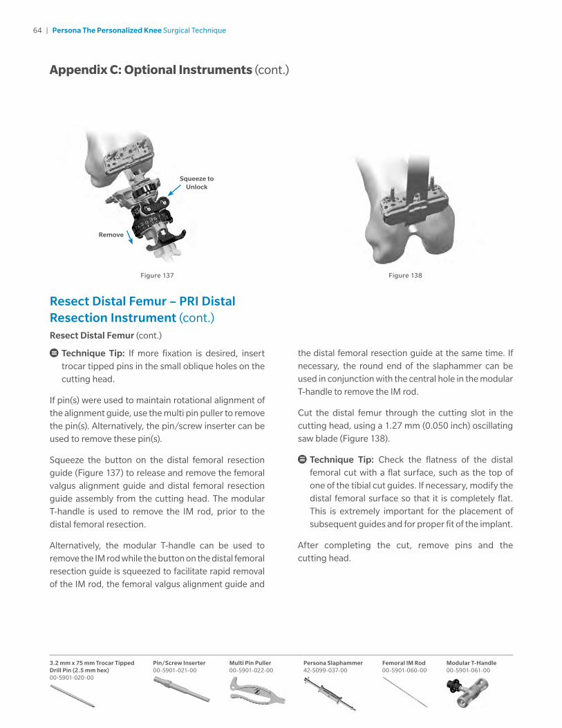
64 | Persona The Personalized Knee Surgical Technique
3.2 mm x 75 mm Trocar Tipped Drill Pin (2.5 mm hex) 00-5901-020-00
Pin/Screw Inserter 00-5901-021-00
Multi Pin Puller 00-5901-022-00
Persona Slaphammer 42-5099-037-00
Femoral IM Rod 00-5901-060-00
Modular T-Handle 00-5901-061-00
Resect Distal Femur – PRI Distal Resection Instrument (cont.) Resect Distal Femur (cont.)
Technique Tip: If more fixation is desired, insert trocar tipped pins in the small oblique holes on the cutting head.
If pin(s) were used to maintain rotational alignment of the alignment guide, use the multi pin puller to remove the pin(s). Alternatively, the pin/screw inserter can be used to remove these pin(s).
Squeeze the button on the distal femoral resection guide (Figure 137) to release and remove the femoral valgus alignment guide and distal femoral resection guide assembly from the cutting head. The modular T-handle is used to remove the IM rod, prior to the distal femoral resection.
Alternatively, the modular T-handle can be used to remove the IM rod while the button on the distal femoral resection guide is squeezed to facilitate rapid removal of the IM rod, the femoral valgus alignment guide and
Figure 137 Figure 138
Appendix C: Optional Instruments (cont.)
the distal femoral resection guide at the same time. If necessary, the round end of the slaphammer can be used in conjunction with the central hole in the modular T-handle to remove the IM rod.
Cut the distal femur through the cutting slot in the cutting head, using a 1.27 mm (0.050 inch) oscillating saw blade (Figure 138).
Technique Tip: Check the flatness of the distal femoral cut with a flat surface, such as the top of one of the tibial cut guides. If necessary, modify the distal femoral surface so that it is completely flat. This is extremely important for the placement of subsequent guides and for proper fit of the implant.
After completing the cut, remove pins and the cutting head.
Squeeze to Unlock
Remove

65 | Persona The Personalized Knee Surgical Technique
Implant ComponentsAttached Tibial Plate Inserter
Depress the lever of the tibial inserter to extend the metal distal tab (Figure 139). Insert the tab into the implant’s dovetails on the central portion of the tibial implant. Slide the tibial inserter posteriorly until the tab engages the dovetails (Figure 140). Release the lever to secure the tibial inserter to the tibial implant. Ensure the tibial inserter is seated flush to the proximal surface of the tibial implant (Figure 141).
Sublux the tibia anteriorly to allow adequate clearance to insert the tibial implant into the prepared bone. Do not apply substances other than bone cement to the tibial implant (i.e. do not dip implant into antibiotics or other substances). Keep the implant clean and free of debris prior to cementing. Place a layer of cement on the underside of the tibial baseplate, around the keel, on the resected tibial surface, and in the tibial IM canal.
Position the tibial plate onto the tibia and use the tibial inserter to impact it until fully seated.
To release the inserter from the implant, depress the lever on the tibial inserter. The handle will move in a superior direction away from the tibial implant (Figure 142). Tilt the handle posteriorly to disengage the distal tab of the inserter from the plate (Figure 143).
Thoroughly remove any excess cement in a consistent manner. Allow the cement to fully cure before performing a trial ROM or inserting the bearing.
Figure 139 Figure 140 Figure 142 Figure 143Figure 141
Persona Cemented Stemmed Tibial Plate Sizes F Right 42-5320-075-02
Persona Tibial Inserter Size E–F 42-5398-092-05
Appendix C: Optional Instruments (cont.)

66 | Persona The Personalized Knee Surgical Technique
Appendix D: Compatibility Charts
CR: Persona CR Femoral/Persona CR Bearing and Tibial Compatibility
Tibial Size
TASP Top & Bottom Color
Femoral Size
1 2 3 4 5 6 7 8 9 10 11 12
A
B
Orange1-2 / A B 3-6 / A B
C
D
Yellow1-2 / C D 3-9 / C D
E
F
Green3-11 / E F
G
H
Blue7-12 / G H
J Gray 9-12 / J
MC: Persona CR Femoral/Persona MC Bearing and Tibial Compatibility
Tibial Size
TASP Top & Bottom Color
Femoral Size
1 2 3 4 5 6 7 8 9 10 11 12
A
B
Orange1-2 / A B 3-4 / A B
C
D
Yellow4-5 / C D 6-7 / C D 8-9 / C D
E
F
Green4-5 / E F 6-7 / E F 8-11 / E F
G
H
Blue8-11 / G H 12 / G H
J Gray 12 / J
UC: Persona CR Femoral/Persona UC Bearing and Tibial Compatibility
Tibial Size
TASP Top & Bottom Color
Femoral Size
1 2 3 4 5 6 7 8 9 10 11 12
A
B
Orange1-2 / A B 3-4 / A B
C
D
Yellow1-2 / C D 3-7 / C D
E
F
Green4-11 / E F
G
H
Blue7-12 / G H
J Gray 9-12 / J

67 | Persona The Personalized Knee Surgical Technique
Appendix D: Compatibility Charts (cont.)
PS: Persona PS Femoral/Persona PS Bearing and Tibial Compatibility
Tibial Size
TASP Top & Bottom Color
Femoral Size
1 2 3 4 5 6 7 8 9 10 11 12
A
B
Orange1-2 / A B 3-5 / A B
C
D
Yellow1-2 / C D 3-5 / C D 6-9 / C D
E
F
Green3-5 / E F 6-9 / E F 10-11 / E F
G
H
Blue6-9 / G H 10-12 / G H
J Gray 10-12 / J
CPS: Persona PS Femoral/Persona Constrained Posterior Stabilized (CPS) Bearing and Tibial Compatibility
Tibial Size
TASP Top & Bottom Color
Femoral Size
1 2 3 4 5 6 7 8 9 10 11 12
A
B
Orange1-2 / A B 3-5 / A B
C
D
Yellow1-2 / C D 3-5 / C D 6-9 / C D
E
F
Green3-5 / E F 6-9 / E F 10-11 / E F
G
H
Blue6-9 / G H 10-12 / G H
J Gray 10-12 / J

68 | Persona The Personalized Knee Surgical Technique
CR: Persona CR Femoral/NexGen CR/CR-Flex Bearing and Tibial Compatibility
Persona CR Femur Used On NexGen CR/CR Flex Bearing (Modular, Fixed Bearing)
NexGen Tibial Size
Persona CR Femoral Size
1 2 3 4 5 6 7 8 9 10 11 12
1
2A-E Micro / 1-2 C-H / 1-2
3
4A-E Micro / 3-4 C-H / 3-4
5
6A-E Micro / 5-6* C-H / 5-6
7
8C-H / 7-10
9
10
All compatibility above applies only to the following NexGen CR/CR-Flex Bearings: 90-5970-XXX-XX, 00/90-5952-XXXX-XX*The A-E Micro / 5-6 NexGen CR/CR-Flex Bearing is only available in Japan, and only in the 00-5952-041-XX family.This information is also available in the Persona Femoral Component package insert.
Persona CR Femur Used On NexGen CR Monoblock Tibia (Trabecular Metal™ Monoblock)
NexGen Tibial Size
Persona CR Femoral Size
1 2 3 4 5 6 7 8 9 10 11 12
1
2
3 C-H / 3
4 C-H / 4
5 C-H / 5
6 C-H / 6
7 C-H / 7
8 C-H / 8
9
10
All compatibility above applies only to the following NexGen Trabecular Metal Monoblocks: 00-5886-04X-XXThis information is also available in the Persona Femoral Component package insert.
Appendix D: Compatibility Charts (cont.)

69 | Persona The Personalized Knee Surgical Technique
Persona PS Femoral/NexGen LPS-Flex Bearing and Tibial Compatibility
Persona PS Femur Used On NexGen LPS-Flex Bearing (Modular, Fixed Bearing)
NexGen Tibial Size
Persona PS Femoral Size
1 2 3 4 5 6 7 8 9 10 11 12
1
2AB / 1-2 CD / 1-2 E / 1-2*
3
4AB / 3-4 CD / 3-4 EF / 3-4 G / 3-4*
5
6CD / 5-6 EF / 5-6 GH / 5-6
7
8EF / 7-10 GH / 7-10
9
10
All compatibility above applies only to the following NexGen LPS-Flex Bearings: 00-5960-XXX-XX, 00-5962-XXX-XX, 00-5964-XXX-XX*The E / 1-2 & G / 3-4 bearings are only available in the 00-5962-XXX-XX family.This information is also available in the Persona Femoral Component package insert.
Appendix D: Compatibility Charts (cont.)

70 | Persona The Personalized Knee Surgical Technique
Persona PS Femur Used On NexGen LPS Monoblock Tibia (Trabecular Metal Monoblock)
NexGen Tibial Size
Persona PS Femoral Size
1 2 3 4 5 6 7 8 9 10 11 12
1
2
3 CD / 3 EF / 3
4 CD / 4 EF / 4
5 CD / 5 EF / 5 GH / 5
6 EF / 6 GH / 6
7 EF / 7 GH / 7
8 GH / 8
9
10
All compatibility above applies only to the following NexGen Trabecular Metal Monoblocks: 00-5886-05X-XX, 00-5886-06X-XX, 00-5886-07X-XXThis information is also available in the Persona Femoral Component package insert.
Appendix D: Compatibility Charts (cont.)

71 | Persona The Personalized Knee Surgical Technique
Notes

72 | Persona The Personalized Knee Surgical Technique
Notes


All content herein is protected by copyright, trademarks and other intellectual property rights, as applicable, owned by or licensed to Zimmer Biomet or its affiliates unless otherwise indicated, and must not be redistributed, duplicated or disclosed, in whole or in part, without the express written consent of Zimmer Biomet.
This material is intended for health care professionals. Distribution to any other recipient is prohibited.
For product information, including indications, contraindications, warnings, precautions, potential adverse effects and patient counseling information, see the package insert and zimmerbiomet.com.
Zimmer Biomet does not practice medicine. This technique was developed in conjunction with [a] health care professional[s]. This document is intended for surgeons and is not intended for laypersons. Each surgeon should exercise his or her own independent judgment in the diagnosis and treatment of an individual patient, and this information does not purport to replace the comprehensive training surgeons have received. As with all surgical procedures, the technique used in each case will depend on the surgeon’s medical judgment as the best treatment for each patient. Results will vary based on health, weight, activity and other variables. Not all patients are candidates for this product and/or procedure.
Check for country product clearances and reference product specific instructions for use. Not for distribution in France.
©2018 Zimmer Biomet
97-5026-001-00 Rev. 13 02/18 MC186921
Authorized RepresentativeZimmer U.K. Ltd.9 Lancaster PlaceSouth Marston ParkSwindon, SN3 4FP, UK
Legal ManufacturerZimmer, Inc. 1800 West Center Street Warsaw, Indiana 46580 USA
zimmerbiomet.com
CE mark on a surgical technique is not valid unless there is a CE mark on the product label.
0086