personal communications for windows, version 5 · personal communications for windows, ... interim...
TRANSCRIPT

Personal Communications for Windows, Version 5.6
Administrator’s Guide and Reference
SC31-8840-01
���


Personal Communications for Windows, Version 5.6
Administrator’s Guide and Reference
SC31-8840-01
���

NoteBefore using this information and the product it supports, read the information in Appendix E, “Notices” on page 367.
Second Edition (September 2002)
This edition applies to Version 5.6 of IBM Personal Communications (program number: 5639–I70) and to allsubsequent releases and modifications until otherwise indicated in new editions.
© Copyright International Business Machines Corporation 1989, 2002. All rights reserved.US Government Users Restricted Rights – Use, duplication or disclosure restricted by GSA ADP Schedule Contractwith IBM Corp.

Contents
Figures . . . . . . . . . . . . . . . ix
Tables . . . . . . . . . . . . . . . xi
About This Book . . . . . . . . . . xiiiWho Should Read This Book . . . . . . . . xiiiHow to Use This Book . . . . . . . . . . xiii
Command Syntax Symbols . . . . . . . . xiiiWhere to Find More Information . . . . . . . xiv
Online Help . . . . . . . . . . . . . xivMessages and Alerts . . . . . . . . . . xivPersonal Communications Library. . . . . . xv
Part 1. General Information . . . . . 1
Chapter 1. Personal CommunicationsHighlights . . . . . . . . . . . . . . 3
Chapter 2. Problem Analysis . . . . . . 9Log Viewer . . . . . . . . . . . . . . . 9Trace Facility . . . . . . . . . . . . . . 9Information Bundler . . . . . . . . . . . 10Internet Service . . . . . . . . . . . . . 11Checking for APARs and CSDs . . . . . . . . 11
Connection Configuration . . . . . . . . 12APARs . . . . . . . . . . . . . . . 12Interim Service Builds . . . . . . . . . . 15Corrective Service Distributions . . . . . . 15
Detect and Repair . . . . . . . . . . . . 15
Part 2. Advanced Configuration,Management, and Operations . . . 17
Chapter 3. Advanced Configuration . . 19Configuration Files . . . . . . . . . . . . 19
Initial Configuration Definitions . . . . . . 19Using Template and Update Files . . . . . . 20
Automatic Device Name Generation (5250 Only) . . 23Substitution Characters . . . . . . . . . 24Client Naming Function . . . . . . . . . 24Device Name Collision Processing . . . . . . 25
Support for Systems Policies. . . . . . . . . 25Support for Management by Tivoli® . . . . . . 25Commands for Emulator Functions . . . . . . 25
Start a Personal Communications Session . . . 26Stop a Personal Communications Session . . . 26Query Personal Communications Sessions . . . 27
Chapter 4. Configuring Multiple Links 29Configuring a Second 3270 Emulation Link . . . . 29Configuring a Second 5250 Emulation Link . . . . 29Configuring a Second Link of a Different Kind . . 30
Configuring to Perform 3270 and 5250 Emulation toMultiple Hosts . . . . . . . . . . . . . 30
Chapter 5. Attachment Considerationsand Adapter Setup Information . . . . 35Attachment Information . . . . . . . . . . 35
COAX Attachment . . . . . . . . . . . 35LAN via IEEE 802.2 Attachment . . . . . . 36TCP/IP Connection. . . . . . . . . . . 36SDLC MPA Attachment . . . . . . . . . 38IBM Global Network - SNA over AsyncAttachment . . . . . . . . . . . . . 39IBM Global Network Connection Attachment . . 39Home3270 Attachment . . . . . . . . . 403270 Attachment via the AS/400 System. . . . 41IBM PC720 Modem Initialization (Japan Only). . 413174 Peer Communications Support (LAN overCoax) . . . . . . . . . . . . . . . 415250 Twinaxial Console . . . . . . . . . 42Twinax Connections Through a 5494 Controllerto an AS/400 . . . . . . . . . . . . . 435250 Asynchronous Console . . . . . . . . 43
Adapter Setup Information . . . . . . . . . 44Creating and Updating Devices in Windows 2000and XP . . . . . . . . . . . . . . . 44Using Coax (3270) Adapters . . . . . . . . 44Twinax Adapters . . . . . . . . . . . 46MPA Adapters . . . . . . . . . . . . 48WAC Attachments . . . . . . . . . . . 50OEM Adapters . . . . . . . . . . . . 51
Chapter 6. Tivoli Support . . . . . . . 53Remote Installation of Personal CommunicationsUsing Tivoli Courier . . . . . . . . . . . 53IBMPCOMM Plus Module for PersonalCommunications . . . . . . . . . . . . 54Task Administration . . . . . . . . . . . 54
Plus Module Administrative Tasks. . . . . . 55Personal Communications Administrative Tasks 55
Event Management . . . . . . . . . . . . 58Personal Communications Events . . . . . . 59Event Management Tasks. . . . . . . . . 60Event Rules . . . . . . . . . . . . . 61Event Adapter . . . . . . . . . . . . 62
Software Distribution . . . . . . . . . . . 63Distribute and Install Personal Communications 64Distribute the SNA Node Configuration Files . . 64Distribute the Emulator Configuration Files . . 64
Signature (Inventory) Information . . . . . . . 65
Chapter 7. System Policy Support . . . 67Configuration Policy . . . . . . . . . . . 68
Communication Configuration . . . . . . . 68Menu Configuration . . . . . . . . . . 68Toolbar Configuration . . . . . . . . . . 69
© Copyright IBM Corp. 1989, 2002 iii
Multiple Sessions Configuration . . . . . . 70Keyboard Configuration . . . . . . . . . 70Mouse Configuration . . . . . . . . . . 71Change Directory . . . . . . . . . . . 71Import . . . . . . . . . . . . . . . 72
Execution Policy . . . . . . . . . . . . . 72Dynamic Menu Modification . . . . . . . 72Java Applet . . . . . . . . . . . . . 73Macro Play/Record. . . . . . . . . . . 73Start Session . . . . . . . . . . . . . 73Delete Session . . . . . . . . . . . . 73Product Update . . . . . . . . . . . . 74File Transfer . . . . . . . . . . . . . 74Detect and Repair . . . . . . . . . . . 74
Installation Policy . . . . . . . . . . . . 74
Chapter 8. Configuring and Using SSLSecurity for Personal Communications . 77What is SSL? . . . . . . . . . . . . . . 77Preparation for SSL Communication . . . . . . 77
Server and Related Client Configuration. . . . 77Client Configuration . . . . . . . . . . 78
Establishing an SSL-Based Session . . . . . . . 79Secure Session Icon . . . . . . . . . . . 79
Configuring Personal Communications for SSLSupport . . . . . . . . . . . . . . . 80
Host Definition . . . . . . . . . . . . 80Automatic Host Location . . . . . . . . . 80Advanced Security Setup . . . . . . . . . 81
Pop-up Messages . . . . . . . . . . . . 82Changing the Password of a Client’s Key Database 82
Using Certificate Wizard . . . . . . . . . 83Using Certificate Management . . . . . . . 83
Configuring SSL for Connecting to a Server Using aCertificate from a Well-Known CA . . . . . . 83Configuring SSL for Connecting to a Server Using aCertificate from an Unknown CA . . . . . . . 84
Opening a Key Database and Adding a RootCertificate . . . . . . . . . . . . . . 84Opening a Key Database and Adding a PersonalCertificate . . . . . . . . . . . . . . 85Obtaining a Personal ID Certificate from aKnown Certificate Authority (CA) . . . . . . 86
Configuring SSL for Connecting to a Server Using aSelf-Signed Certificate . . . . . . . . . . . 87Security References . . . . . . . . . . . . 87Problem Determination . . . . . . . . . . 87Smart Card Support . . . . . . . . . . . 88
Enabling Smart Card Support . . . . . . . 88Using the IKEYCMD Command-Line Interface . . 89
Environment Setup for IKEYCMDCommand-Line Interface . . . . . . . . . 89IKEYCMD Command Line Syntax . . . . . . 90IKEYCMD Tasks for Personal Communications 92Creating a new key database . . . . . . . 93Creating a new key pair and certificate request 94Creating a self-signed certificate . . . . . . 95Exporting keys . . . . . . . . . . . . 95Importing keys . . . . . . . . . . . . 96Listing CAs . . . . . . . . . . . . . 96Storing the CA certificate . . . . . . . . . 96
Opening a key database . . . . . . . . . 97Showing the default key in a key database . . . 97Using GSK6CMD batch file . . . . . . . . 98Summary of Command-Line Invocations . . . 98
Chapter 9. ODBC Drivers andDatabase Access Utility . . . . . . . 101Overview of Open Database Connectivity (ODBC) 101
Components of ODBC . . . . . . . . . 102Database Access Utility . . . . . . . . . . 103
Accessing an ODBC Data Source . . . . . . 103Database Size Limit . . . . . . . . . . 105
Chapter 10. Express Logon Feature 107Using Express Logon . . . . . . . . . . . 107Preparing to Configure the Express Logon Feature 107Configuring Express Logon. . . . . . . . . 108
Recording the Macro . . . . . . . . . . 108Manual Configuration of an ELF Macro . . . 108Limitations of the Logon Macro . . . . . . 108
Problem Determination . . . . . . . . . . 109
Part 3. SNA and AnyNet Topics 111
Chapter 11. SNA Client/ServerConcepts . . . . . . . . . . . . . 113Terminology . . . . . . . . . . . . . . 113APPC Concepts. . . . . . . . . . . . . 113
Introducing APPC and CPI-C . . . . . . . 114What Is a Transaction Program? . . . . . . 114What Is the Difference between APPC andAPPN? . . . . . . . . . . . . . . 115Side Information Definitions . . . . . . . 115Improving Productivity Using APPC . . . . 116Improving Productivity Using CPI-C . . . . 116What Is a Logical Unit? . . . . . . . . . 116LU Types . . . . . . . . . . . . . . 117Dependent and Independent LUs. . . . . . 117What Is a Session?. . . . . . . . . . . 117What Is a Conversation?. . . . . . . . . 118A Conversation between Two TPs . . . . . 119Parallel Sessions between LUs . . . . . . . 119
SNA Communications . . . . . . . . . . 119SNA Node Operations . . . . . . . . . . 120
Chapter 12. AnyNet SNA over TCP/IP 121What Does AnyNet SNA over TCP/IP Do? . . . 121
Running APPC or CPI-C Applications over aTCP/IP Network . . . . . . . . . . . 121Using AnyNet to Connect SNA Applications onDifferent Platforms . . . . . . . . . . 121Chaining Gateways to Connect Multiple SNAand IP Networks . . . . . . . . . . . 1225250 Emulation over a TCP/IP Network . . . 123APPC3270 Emulation over a TCP/IP Network 1233270 Emulation via DLUR over a TCP/IPNetwork . . . . . . . . . . . . . . 124
iv Personal Communications Administrator’s Guide and Reference
3270 Emulation over a TCP/IP Network via anSNA Gateway to a VTAM® Host on an SNANetwork . . . . . . . . . . . . . . 1243270 Emulation over a TCP/IP Network via anSNA Gateway to a VTAM Host on an APPNNetwork . . . . . . . . . . . . . . 1253270 Emulation via an SNA Gateway over aTCP/IP Network . . . . . . . . . . . 125
How Does SNA over TCP/IP Work? . . . . . 126Mapping SNA Resources to IP Addresses . . . . 127Defining Domain Names and IP Addresses . . . 128Defining Unique CP Names and ConnectionNetwork Names . . . . . . . . . . . . 129Setting and Modifying the Routing PreferenceProtocol . . . . . . . . . . . . . . . 130Helpful Hints . . . . . . . . . . . . . 131
Tuning . . . . . . . . . . . . . . 131Connecting to AS/400 . . . . . . . . . 131Dynamic IP Addresses . . . . . . . . . 131
AnyNet Configuration Examples . . . . . . . 132Example 1. 5250 Emulation Over a TCP/IPNetwork . . . . . . . . . . . . . . 132Example 2. Running APPC or CPI-CApplications over a TCP/IP Network . . . . 133Example 3. APPC3270 Emulation over a TCP/IPNetwork . . . . . . . . . . . . . . 134Example 4. 3270 Emulation via DLUR over aTCP/IP Network . . . . . . . . . . . 135Example 5. 3270 Emulation over a TCP/IPNetwork via a SNA Gateway to a VTAM Hoston a SNA Network . . . . . . . . . . 137Example 6. 3270 Emulation via an SNAGateway over a TCP/IP Network . . . . . 138Example 7. 3270 Emulation over a TCP/IPNetwork via an AnyNet SNA/IP Gateway to aVTAM Host on an APPN Network . . . . . 139Example 8. 3270 Emulation from a Windows NTWorkstation and a Windows 95 Workstation onDifferent IP Networks . . . . . . . . . 140
Part 4. National Language Support 143
Chapter 13. Multiple-LanguageSupport . . . . . . . . . . . . . . 145Overview. . . . . . . . . . . . . . . 145
System Locale . . . . . . . . . . . . 145Language Groups . . . . . . . . . . . 145
Personal Communications User InterfaceLanguages . . . . . . . . . . . . . . 146Multiple Sessions . . . . . . . . . . . . 147Other Considerations . . . . . . . . . . . 147
Chapter 14. Country Codes andCharacter Sets . . . . . . . . . . . 149Keyboard Country ID and Shift Support . . . . 150IBM Japanese Character Set (2-Byte Codes) . . . 152
Character Types . . . . . . . . . . . 152Character Size . . . . . . . . . . . . 152IBM Kanji Codes . . . . . . . . . . . 152IBM Traditional Chinese Character Set . . . . 153
IBM Simplified Chinese Character Set, GBKCode . . . . . . . . . . . . . . . 154IBM Hangeul Character Set. . . . . . . . 154Thai Language Support . . . . . . . . . 155
Chapter 15. Bidirectional LanguageSupport (Arabic and Hebrew) . . . . 157Considerations for Printing . . . . . . . . . 157
Printing in Arabic . . . . . . . . . . . 157DAT File for 5250 Arabic . . . . . . . . 157
Bidirectional Arabic Support . . . . . . . . 158Limitations . . . . . . . . . . . . . 158Installation Tips . . . . . . . . . . . 158Bidirectional Keyboard Functions for 3270 . . . 158Arabic Character Shape Selection Functions . . 160Personal Communications AS/400 . . . . . 161
Bidirectional Hebrew Support . . . . . . . . 162Bidirectional Functions for 3270 . . . . . . 162Keyboard Layout . . . . . . . . . . . 164Configuration . . . . . . . . . . . . 164Font . . . . . . . . . . . . . . . 165File Transfer With 862 Code Page. . . . . . 165Bidirectional Functions for 5250 . . . . . . 165
Bidirectional Support for VT . . . . . . . . 166Configuring VT Emulation for Arabic orHebrew . . . . . . . . . . . . . . 166File Transfer . . . . . . . . . . . . . 166Copy and Paste . . . . . . . . . . . 167Print Screen . . . . . . . . . . . . . 167Remapping BiDi Keys . . . . . . . . . 167Bidirectional Functions for VT . . . . . . . 167Arabic Support for ASMO 449 7-bit Code Page 168
Chapter 16. Unicode Support . . . . 1691390/1399 Code Pages . . . . . . . . . . 169Hindi Support . . . . . . . . . . . . . 170
Part 5. Building a Printer DefinitionTable (PDT) . . . . . . . . . . . 173
Chapter 17. Building a PrinterDefinition Table (PDT) for PC/3270 . . 175ASCII_PASSTHRU? and EBCDIC_PASSTHRU? . . 175Supplemental Explanation of PDF Statements forPC/3270 . . . . . . . . . . . . . . . 175SCS TAB Setting . . . . . . . . . . . . 177Printer Color Mixing . . . . . . . . . . . 177Printer Session Data Stream Support . . . . . 177
3270 Data Stream . . . . . . . . . . . 178SCS Data Stream . . . . . . . . . . . 179
Delimiting Print Jobs . . . . . . . . . . . 180Structured Fields . . . . . . . . . . . . 181
Begin/End of File Query Reply . . . . . . 181Begin/End of File Structured Fields . . . . . 181
Chapter 18. Building a PrinterDefinition Table (PDT) for PC400 . . . 185Using the Printer Definition Table (PDT) File . . . 185Printer Definition File (PDF File) Format . . . . 185
Contents v

Macro Definitions . . . . . . . . . . . 185Formatting Controls . . . . . . . . . . 187
Transparent Print Capability . . . . . . . . 189ASCII_PASSTHRU? Keyword Support . . . . 189EBCDIC_PASSTHRU? Keyword Support . . . 190EBCDIC_xx Keyword Support. . . . . . . 190
Printer Definition Tables. . . . . . . . . . 191Example Printer Definition Files . . . . . . . 191
IBM4019.PDF File Contents. . . . . . . . 191IBM5577.PDF File Contents. . . . . . . . 199
Field Names of Printer Definition Files . . . . . 201Symbols of Printer Definition Files . . . . . . 208Using Printer Control Codes . . . . . . . . 213
Printer Control Code Format . . . . . . . 213Parameter Definition of Printer Control Codes 213Supported Control Codes . . . . . . . . 214Supported SCS Commands . . . . . . . . 214Programming Notes . . . . . . . . . . 217Restrictions and Notes for AS/400 PrinterCommands and Printer Setup . . . . . . . 217
PFT Migration Utility. . . . . . . . . . . 222Using the PFT Migration Utility . . . . . . 222Details of Migration . . . . . . . . . . 223
Part 6. Appendixes . . . . . . . . 247
Appendix A. Keyboard Layouts. . . . 249Local Edit Keys. . . . . . . . . . . . . 250Keyboard Layouts . . . . . . . . . . . . 251
Enhanced Keyboard, Microsoft NaturalKeyboard (3270 Only) . . . . . . . . . 255Enhanced Keyboard, Microsoft NaturalKeyboard (5250 Only) . . . . . . . . . 257Enhanced Keyboard, Microsoft NaturalKeyboard (Combined 3270 and 5250) . . . . 259Enhanced Keyboard, Microsoft NaturalKeyboard (VT Keyboard Layout) . . . . . . 261Enhanced Keyboard, Microsoft NaturalKeyboard (VT Local Edit Mode Only) . . . . 263Space-Saving Keyboard (3270 Only) . . . . . 265Space-Saving Keyboard (5250 Only) . . . . . 267Space-Saving Keyboard (Combined 3270 and5250) . . . . . . . . . . . . . . . 2695576-001 (3270 Only) . . . . . . . . . . 2715576-001 (5250 Only) . . . . . . . . . . 2735576-001 (Combined 3270 and 5250) . . . . . 2755576-A01 (3270 Only). . . . . . . . . . 2775576-A01 Keyboard (5250 Only) . . . . . . 2795576-A01 Keyboard (Combined 3270 and 5250) 2815576-002/003 (3270 Only) . . . . . . . . 2835576-002/003 Keyboard (5250 Only) . . . . . 2855576-002/003 Keyboard (Combined 3270 and5250) . . . . . . . . . . . . . . . 287
APL Keyboard Layouts (3270 Only) . . . . . . 288Key Map for Home3270 . . . . . . . . . . 290
Appendix B. AS/400 ConfigurationExamples . . . . . . . . . . . . . 293AS/400 Device Description . . . . . . . . . 2945250 Sessions through One Link . . . . . . . 294
AS/400 System Mode Description . . . . . . 295AS/400 Device Description for TwinaxialAttachments (APPC) Example . . . . . . . . 296AS/400 Device Description for AsynchronousAttachment Example . . . . . . . . . . . 297AS/400 VT Asynchronous Attachment Example 301AS/400 Configuration for SDLC Example . . . . 303
Network Attributes . . . . . . . . . . 303SDLC Leased Configuration . . . . . . . . 304
Creating an SDLC Line Description . . . . . 304SDLC Controller Description . . . . . . . 306
SDLC Switched Configuration . . . . . . . . 307SDLC Line Description . . . . . . . . . 307SDLC Controller Description . . . . . . . 309
LAN Configuration Example . . . . . . . . 310LAN Controller Description . . . . . . . 311
Appendix C. Host Code Page Tables 313Host Code Page 037-1/697-1 Brazil, Canada,Netherlands, Portugal, U.S., and 037/1175Traditional Chinese . . . . . . . . . . . 314Host Code Page 273-1/697-1 Austria, Germany . . 315Host Code Page 275-1/697-1 Brazil . . . . . . 316Host Code Page 277-1/697-1 Denmark, Norway 317Host Code Page 278-1/697-1 Finland, Sweden . . 318Host Code Page 280-1/697-1 Italy . . . . . . 319Host Code Page 284-1/697-1 Latin America, Spain 320Host Code Page 285-1/697-1 United Kingdom . . 321Host Code Page 290 Japan (Katakana) Extended 322Host Code Page 297-1/697-1 France . . . . . . 323Host Code Page 420 Arabic Bilingual . . . . . 324Host Code Page 424/941 Israel (Hebrew - BulletinCode) . . . . . . . . . . . . . . . . 325Host Code Page 500-1/697-1 International . . . . 326Host Code Page 803 Israel (Hebrew - Old Code) 327Host Code Page 833/1173 Hangeul . . . . . . 328Host Code Page 836/1174 Simplified Chinese . . 329Host Code Page 870/959 Latin 2 - EBCDICMultilingual . . . . . . . . . . . . . . 330Host Code Page 871-1/697-1 Iceland . . . . . 331Host Code Page 875 Greece . . . . . . . . 332Host Code Page 924-1/1353-1 International . . . 333Host Code Page 1025/1150 Cyrillic . . . . . . 334Host Code Page 1026/1152 Latin 5 - Turkey . . . 335Host Code Page 1027/1172 Japan (Latin) Extended 336Host Code Page 1047/103 Latin 1 (Open Systems) 337Host Code Page 1112/1035 Latvia, Lithuania . . . 338Host Code Page 1122/1037 Estonia . . . . . . 339Host Code Page 1123 Ukraine . . . . . . . . 340Host Code Page 1130 Vietnam . . . . . . . . 341Host Code Page 1132 Laos . . . . . . . . . 342Host Code Page 1137 India . . . . . . . . . 343Host Code Page 1140-1/695-1 Brazil, Canada,Netherlands, Portugal, U.S., and 1140/1175Traditional Chinese . . . . . . . . . . . 344Host Code Page 1141-1/695-1 Austria, Germany 345Host Code Page 1142-1/695-1 Denmark, Norway 346Host Code Page 1143-1/695-1 Finland, Sweden . . 347Host Code Page 1144-1/695-1 Italy . . . . . . 348Host Code Page 1145-1/695-1 Latin America, Spain 349Host Code Page 1146-1/695-1 United Kingdom . . 350
vi Personal Communications Administrator’s Guide and Reference

Host Code Page 1147-1/695-1 France . . . . . 351Host Code Page 1148-1/695-1 International . . . 352Host Code Page 1149-1/695-1 Iceland . . . . . 353Host Code Page 1153/1375 Latin 2 - EBCDICMultilingual . . . . . . . . . . . . . . 354Host Code Page 1154/1381 Cyrillic . . . . . . 355Host Code Page 1155/1378 Latin 5 - Turkey . . . 356Host Code Page 1156/1393 Latvia, Lithuania . . . 357Host Code Page 1157/1391 Estonia . . . . . . 358Host Code Page 1158/1388 Ukraine . . . . . . 359
Host Code Page 1160/1395 Thailand . . . . . 360Host Code Page 1164/1397 Vietnam . . . . . . 361
Appendix D. Alerts . . . . . . . . . 363
Appendix E. Notices . . . . . . . . 367Trademarks . . . . . . . . . . . . . . 368
Index . . . . . . . . . . . . . . . 371
Contents vii

viii Personal Communications Administrator’s Guide and Reference

Figures
1. Database Access Overview . . . . . . . 1012. ODBC Components . . . . . . . . . 1023. A Session between Two LUs . . . . . . 1184. A Conversation between Two TPs. . . . . 1195. Parallel Sessions between LUs . . . . . . 1196. Running APPC or CPI-C Applications over a
TCP/IP Network . . . . . . . . . . 1217. Using AnyNet to Connect SNA Applications
on Different Platforms . . . . . . . . 1228. Chaining Multiple Gateways to Connect
Multiple IP Networks . . . . . . . . . 1239. 5250 Emulation over a TCP/IP Network 123
10. APPC3270 Emulation over a TCP/IPNetwork . . . . . . . . . . . . . 124
11. 3270 Emulation via DLUR over a TCP/IPNetwork . . . . . . . . . . . . . 124
12. 3270 Emulation over a TCP/IP Network viaan SNA Gateway to a VTAM Host on anSNA Network . . . . . . . . . . . 125
13. 3270 Emulation over a TCP/IP Network viaan SNA Gateway to a VTAM Host on anAPPN Network . . . . . . . . . . . 125
14. 3270 Emulation via an SNA Gateway over aTCP/IP Network . . . . . . . . . . 126
15. Structure of SNA over TCP/IP for PersonalCommunications . . . . . . . . . . 127
16. Formats of the Domain Names That SNAover TCP/IP Builds . . . . . . . . . 128
17. Defining a CP Name and a ConnectionNetwork Name . . . . . . . . . . . 130
18. 5250 Emulation Over a TCP/IP Network 13219. Running APPC or CPI-C Applications over a
TCP/IP Network . . . . . . . . . . 13320. APPC3270 Emulation over a TCP/IP
Network . . . . . . . . . . . . . 13521. 3270 Emulation via DLUR over a TCP/IP
Network . . . . . . . . . . . . . 13622. 3270 Emulation over a TCP/IP Network via a
SNA Gateway to a VTAM Host on a SNANetwork . . . . . . . . . . . . . 137
23. 3270 Emulation via an SNA Gateway over aTCP/IP Network . . . . . . . . . . 138
24. 3270 Emulation over a TCP/IP Network viaan AnyNet SNA/IP Gateway to a VTAMHost on an APPN Network . . . . . . . 139
25. 3270 Emulation on Different IP Networks 14026. Type-1 APL Keyboard. . . . . . . . . 28927. Type-2 APL Keyboard. . . . . . . . . 28928. Type-3 APL Keyboard. . . . . . . . . 28929. Type-4 APL Keyboard. . . . . . . . . 29030. Common Control Code of Keyboard Core
Segment for Non-Japanese Keyboard. . . . 29031. Common Control Code of Keyboard Core
Segment for Japanese Keyboard . . . . . 29132. Control-Code Map of Keyboard Core
Segment for U.S. Enhanced Keyboard . . . 29233. LAN Attachment via IEEE 802.2 . . . . . 293
© Copyright IBM Corp. 1989, 2002 ix

x Personal Communications Administrator’s Guide and Reference
Tables
1. Supported Netscape PKCS#11-compatibleSmart Card Drivers . . . . . . . . . . 88
2. Object-Action Pairs for IKEYCMD . . . . . 903. Command-Line Options for IKEYCMD 914. Supported Keyboard Types . . . . . . . 1495. Keyboard Country ID and Shift Support 1506. The IBM Japanese Character Set and IBM
Kanji Codes . . . . . . . . . . . . 1527. The IBM Japanese Character Set and IBM
Kanji Codes (Extended for Unicode Subset) . 1538. IBM Traditional Chinese Host Code . . . . 1539. IBM Simplified Chinese Character Set, GBK
Code . . . . . . . . . . . . . . 15410. IBM Hangeul Host Code (833) . . . . . . 15411. IBM Hangeul Host Code (1364) . . . . . 15512. Bidirectional Key-Combinations for 3270 16213. Bidirectional Key-Combinations for 5250 16514. Bidirectional Key-Combinations for VT 16715. Control Sequences for Arabic VT Support 16816. Color Mixes . . . . . . . . . . . . 17717. 3270 Data Stream Commands . . . . . . 17818. 3270 Data Stream Orders. . . . . . . . 17819. 3270 Data Stream Format Control Codes 179
20. Supported SCS Control Codes . . . . . . 17921. Begin/End of File Query Reply Format 18122. Begin/End of File Structured Field Format 18123. Field Names of PDF Files . . . . . . . 20124. Effective Values for PDF File Field Names 20725. Printer Symbol Definitions . . . . . . . 20826. Printer Control Code Parameter Types 21327. Supported SCS Commands . . . . . . . 21428. Printer Control Codes. . . . . . . . . 21729. SCD Parameter Values . . . . . . . . 21830. Commonly Used SFG GFID Values . . . . 21831. AS/400 Font Parameters . . . . . . . . 21932. PDF File Name . . . . . . . . . . . 22333. Migration from the Printer Function Table to
the Printer Definition File . . . . . . . 22334. New Keyboard Map Functions for a 5250
Layout . . . . . . . . . . . . . . 24935. New Keyboard Map Functions for a 3270
Layout . . . . . . . . . . . . . . 24936. Key Combinations for Upper-Right and
Lower-Right Characters . . . . . . . . 25037. Local Edit Keys . . . . . . . . . . . 25038. Other Control Code Map of Key Segment B 291
© Copyright IBM Corp. 1989, 2002 xi

xii Personal Communications Administrator’s Guide and Reference

About This Book
IBM® Personal Communications for Windows® reference books are comprised offour volumes: a 3270 Emulator User’s Reference, a 5250 Emulator User’s Reference,a VT Emulator User’s Reference and an Administrator’s Guide and Reference.These volumes provide information for using IBM Personal CommunicationsAS/400® for Windows operating systems (hereafter called PC400) and IBMPersonal Communications for Windows operating systems. In this book, Windowsrefers to Windows 95, Windows 98, Windows NT, Windows Me, Windows 2000,and Windows XP. When information is applies only to a specific operatingsystems, this is indicated in the text. PC/3270 refers to the 3270 portion of thecombined package. Throughout this book, workstation refers to all supportedpersonal computers. When only one model or architecture of the personalcomputer is referred to, only that type is specified.
Who Should Read This BookThis book is intended for administrators of Personal Communications.
How to Use This BookThis book contains reference information that you might need to refer to wheninstalling or operating Personal Communications.
Personal Communications is designed to use various communication adapters andto work with other workstation and host system software. Refer to the appropriatedocumentation for the products you use.
Command Syntax SymbolsParentheses, brackets, ellipses, and slashes have the following meanings or uses:
( ) Parentheses enclose operands that govern the action of certain commandoptions.
[ ] Brackets indicate an optional command argument. If you do not use theoptional item, the program selects a default.
... Ellipsis after an argument indicates that you can repeat the preceding itemany number of times.
/ For 3270, a slash must precede the Time Sharing Option Extensions(TSO/E) password. A slash must also precede parameters of DOScommands entered from the command line. For 5250, a slash must precedeparameters of IBM DOS commands entered from the command line.
\ A backslash is included as part of any directory name. An initial backslashindicates the first-level directory, and an additional backslash is inserted inthe directory name to indicate another level.
All directives, operands, and other syntax can be typed in either uppercase orlowercase, unless otherwise indicated.
© Copyright IBM Corp. 1989, 2002 xiii

Where to Find More Information
Online HelpThe help facility describes how to install, configure, and use PersonalCommunications. Online help is very extensive and includes information aboutevery aspect of configuring and using Personal Communications.
Use help to obtain the following information:v Menu choicesv Operation proceduresv Operations in windowsv Meanings of the terms displayed in windowsv Causes of errors and the corresponding actions to takev Mouse-based operationsv Operation without a mousev Detailed explanations of specific termsv Further technical information about Personal Communicationsv Detailed explanations of operator information area (OIA) messages
To display online help, select choices from the Help menu or press F1.
You can use Personal Communications online help just as you use the online helpfor Windows.
Messages and AlertsOnline messages are displayed by Personal Communications, but a message doesnot always mean an error occurred. For example, a message might tell you that anoperation is in progress or has been completed. A message can also prompt you towait for the completion of an operation.
Messages That Appear in Pop-Up WindowsWhile using Personal Communications, you may see messages appear in popupwindows, but not necessarily as a direct result of your actions. These messages canappear for a number of reasons, outlined in the following sections.
System-Fault Messages: For Windows NT®, if a message does appear in a pop-upwindow, you can paste its contents into the Windows NT clipboard. To do this:1. Click Details on the pop-up window.2. Mark the text that you want to copy.3. Click the marked text with the right mouse button and then click Copy.4. Start an editor, such as Notepad, and click Paste from the Edit menu.5. Save the file in case an IBM Service Representative needs this information to
diagnose your problem.
Security-Related Messages: Personal Communications optionally utilizes SecureSockets Layer (SSL) to establish sessions with servers; this may require input fromyou (for example, a password). See Chapter 8, “Configuring and Using SSLSecurity for Personal Communications” on page 77 for details.
System-Policy-Related Messages: Your Personal Communications workstationconfiguration can be controlled centrally using facilities for managing systempolicies. See Chapter 7, “System Policy Support” on page 67 for details.
xiv Personal Communications Administrator’s Guide and Reference

OIA Messages
Personal Communications displays messages in the operator information area(OIA) or in a pop-up window. Messages from Personal Communications aredisplayed in the message window; messages from the host system regarding thecondition of the session are displayed in the OIA of the session window.
The OIA is the bottom line of the session window. An OIA message indicates thestatus of Personal Communications as well as information about the workstation,host system, and attachment method.
All of the OIA indicators, reminders, and messages are described in the onlinehelp. To view this information:1. Click Index from the Help menu.2. Select The operator information area messages.
To look up a specific OIA message, select Search. When the Search windowappears, type the letters that appear in the OIA. For example, MACH or PROG. If alightning bolt appears, type COMM.
3. Double-click the index entry that matches your search.4. Scroll through the window until you find the number that appears in your
OIA.
AlertsAlerts may be generated which correspond to specific Personal Communicationsmessages. See Appendix D, “Alerts” on page 363 for more information.
Personal Communications LibraryThe Personal Communications library includes the following publications:v IBM Personal Communications for Windows, Version 5.6 CD-ROM Guide to
Installation, GC31-8079-07v IBM Personal Communications AS/400 for Windows, Version 5.6 CD-ROM Guide to
Installation, GC31-8080-07v IBM Personal Communications for Windows, Version 5.6 Quick Beginnings,
GC31-8679-03v IBM Personal Communications for Windows, Version 5.6 Access Feature, SC31-8684-03v IBM Personal Communications for Windows, Version 5.6 5250 Emulator User’s
Reference, SC31-8837-01v IBM Personal Communications for Windows, Version 5.6 3270 Emulator User’s
Reference, SC31-8838-01v IBM Personal Communications for Windows, Version 5.6 VT Emulator User’s
Reference, SC31-8839-01v IBM Personal Communications for Windows, Version 5.6 Administrator’s Guide and
Reference, SC31-8840-01v IBM Personal Communications for Windows, Version 5.6 Emulator Programming,
SC31-8478-06v IBM Personal Communications for Windows, Version 5.6 Client/Server
Communications Programming, SC31-8479-06v IBM Personal Communications for Windows, Version 5.6 System Management
Programming, SC31-8480-06v IBM Personal Communications for Windows, Version 5.6 CM Mouse Support User’s
Guide and Referencev IBM Personal Communications for Windows, Version 5.6 Host Access Class Library,
SC31-8685-03
About This Book xv

v IBM Personal Communications for Windows, Version 5.6 Configuration File Reference,SC31-8655-05
These books are also available (except in DBCS versions) in PDF format and areoptionally installed or viewed from the CD-ROM.
In addition to the printed books, there are HTML documents provided withPersonal Communications:
Host Access Class Library for JavaThis HTML document describes how to write an ActiveX/OLE2.0–compliant application to use Personal Communications as anembedded object.
Host Access Beans for JavaThis HTML document describes Personal Communications emulatorfunctions delivered as a set of JavaBeans™.
xvi Personal Communications Administrator’s Guide and Reference

Part 1. General Information
© Copyright IBM Corp. 1989, 2002 1

2 Personal Communications Administrator’s Guide and Reference
Chapter 1. Personal Communications Highlights
Personal Communications brings the power of personal networking to yourworkstation by providing a variety of connectivity options supporting local areanetwork (LAN) and wide area network (WAN) environments. Whether you needhost terminal emulation, client/server applications, or connectivity, PersonalCommunications offers a robust set of communications, networking, andadministrative features.
Personal Communications is a full-function emulator package with an easy-to-usegraphical interface, which includes many useful features such as file transfer anddynamic configuration, and emulator APIs including the IBM Host Access ClassLibrary.
Personal Communications also provides a variety of SNA-based client applicationprogramming interfaces (APIs). You can create applications that use thepeer-to-peer client APIs, which are based on LU 6.2 (and provided by PersonalCommunications). Using these APIs you can simultaneously access and processinformation on peer workstations.
With Personal Communications, you can participate in Advanced Peer-to-PeerNetworking® (APPN®) as an end node, and use the advanced network features,high-performance routing (HPR), and dependent LU requester (DLUR).
Personal Communications provides the following functions:v System/390® Connections
LAN LAN via IEEE 802.2Communications Server for Windows NTTelnet32703270 via AS/400APPC 3270 via LANMicrosoft® SNA client over FMIDependent Logical Unit Requester (DLUR)VT-over-Telnet (TCP/IP)3174 Peer Communication
COAX SNA Distributed Function TerminalNon-SNA Distributed Function Terminal
COM portTelnet 3270SNA-over-AsyncIBM Global Network® (not in Japan)Home3270IBM Global Network - SNA-over-AsyncDependent Logical Unit Requester (DLUR) via
SNA-over-Async
Hayes AutoSyncAPPC 3270 via SNA-over-AsyncAPPC 3270 via Hayes AutoSyncVT-over-AsyncVT-over-Telnet (TCP/IP)X.25 Hayes AutoSyncX.25 DLUR via Hayes AutoSync
© Copyright IBM Corp. 1989, 2002 3
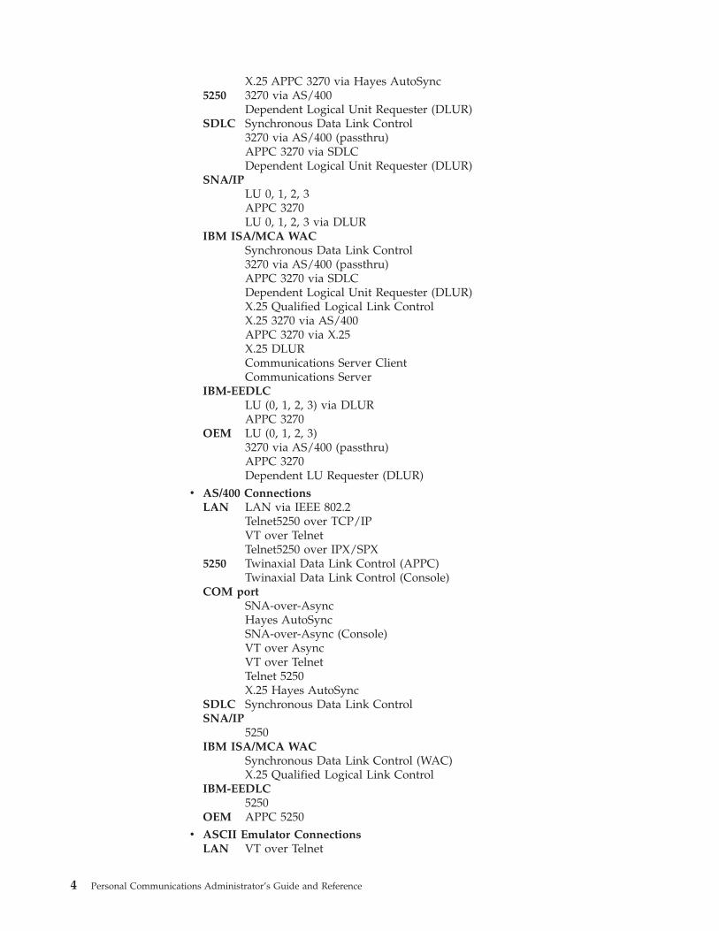
X.25 APPC 3270 via Hayes AutoSync5250 3270 via AS/400
Dependent Logical Unit Requester (DLUR)SDLC Synchronous Data Link Control
3270 via AS/400 (passthru)APPC 3270 via SDLCDependent Logical Unit Requester (DLUR)
SNA/IPLU 0, 1, 2, 3APPC 3270LU 0, 1, 2, 3 via DLUR
IBM ISA/MCA WACSynchronous Data Link Control3270 via AS/400 (passthru)APPC 3270 via SDLCDependent Logical Unit Requester (DLUR)X.25 Qualified Logical Link ControlX.25 3270 via AS/400APPC 3270 via X.25X.25 DLURCommunications Server ClientCommunications Server
IBM-EEDLCLU (0, 1, 2, 3) via DLURAPPC 3270
OEM LU (0, 1, 2, 3)3270 via AS/400 (passthru)APPC 3270Dependent LU Requester (DLUR)
v AS/400 ConnectionsLAN LAN via IEEE 802.2
Telnet5250 over TCP/IPVT over TelnetTelnet5250 over IPX/SPX
5250 Twinaxial Data Link Control (APPC)Twinaxial Data Link Control (Console)
COM portSNA-over-AsyncHayes AutoSyncSNA-over-Async (Console)VT over AsyncVT over TelnetTelnet 5250X.25 Hayes AutoSync
SDLC Synchronous Data Link ControlSNA/IP
5250IBM ISA/MCA WAC
Synchronous Data Link Control (WAC)X.25 Qualified Logical Link Control
IBM-EEDLC5250
OEM APPC 5250v ASCII Emulator Connections
LAN VT over Telnet
4 Personal Communications Administrator’s Guide and Reference

COM portVT-over-AsyncVT over Telnet
v S/3X Emulator Connections5250 Twinaxial Data Link Control (Console)
v Client/Server ConnectionsLAN LAN via IEEE 802.2Twinaxial
Twinaxial Data Link Control (APPC)COM port
SNA-over-AsyncHayes AutoSyncX.25
SDLC Synchronous Data Link ControlIBM WAC
Synchronous Data Link ControlX.25
AnyNet® SNA over TCP/IPAPPC
Enterprise ExtenderHPR over IP
v Configuration of SNA Node (APPN) Sessions– Emulator– Client/server applications
v SNA Node Operations– Starting and stopping resources– Deleting resources– Displaying resource information– Changing session limits– Initiation of path switches
v Log Viewer– View Message Log, Trace Log, and Merged Log files– Summary and Detail views– Set default Message Log size and location– Filter and search Log files– Message Log entries Help
v Trace Capability– 3270/5250 emulator data– APPN and APPC API data– Connectivity data, such as LAN or SDLC– User services data, such as node initialization
v APPC Applets– Display SNA sense data (GETSENSE)– Transfer files (AFTP and AFTPD)– Check connection (APING)
v Sample Programs
– Located in \Personal Communications\samples subdirectoryv Installation and Configuration
– Partial installation option– Program sharing on a network server– Automatic detection of installed communication adapters– Dynamic change of communication configurations– Automatic Dial Facility (Async (IGN), SDLC, Home3270, SNA-A)
Chapter 1. Personal Communications Highlights 5

– Silent Installation– ASCII SNA-node configuration– Verification of ASCII configuration
v OEM Adaptor Cards
An open API enables vendors and other equipment manufacturers (OEMs) toprovide adapter cards that allow for additional connectivity options, forexample, additional X.25, ISDN, SDLC or twinax support.
v Host Session Function– Up to 26 sessions– Variable screen size and automatic font scaling– Function settings (of the host code page, for example) for each session
v Host Graphics Support– Built-in vector graphics support for GDDM® and other graphics applications
v File Transfer Function– Easy operation through graphical user interface (GUI) windows– Batch transfer of multiple files– Concurrent file transfer through multiple sessions– Background file transfer– File transfer invocation by macro– OfficeVision/MVS™ Import/Export functions– VT File Transfer (XModem and YModem)
v Edit (Cut and Paste) Function
You can use the clipboard to cut, copy, and paste a selected areaIn addition, youcan paste data in other applications, such as spreadsheet programs, that supportthe PasteLink function.– Support of spreadsheet data format (Sylk, Biff3, Wk3 formats)– Copy Append– Paste Next– Paste to Trim Rectangle– Paste Stop at Protected Line
v Graphical User Interface (GUI)– Customizable 3D iconic tool bar– 3D-button hotspots– Pop-up keypad– Macro function, including record and play– VBScripts, including record and play– Keyboard-function setup and remapping– Mouse-button-function setup and remapping– Display setup (cursor type, graphics, sound, colors, for example)– Automatic font size adjustment or fixed font size– Window-appearance setup– Menu-bar customization– 3270 Light Pen emulation by using a mouse– Status bar with history– Page setup (Text and Graphics)– Revised Configuration Dialog– Online help
v Print Function– Printer session (for PC/3270: SCS, LU 3, or non-SNA)– Graphics local print– Printing with the Windows NT printer drivers– Print function by printer definition table (PDT)– Multiple host-print functions in multiple sessions– Print-job control by SNA bracket timeout
6 Personal Communications Administrator’s Guide and Reference

– PDF-to-PDT conversion tool– PC400 print function by OS/400® Host Print Transform (HPT)– PC400 printing supported by the AS/400 Advanced Print Support Utility– ZipPrint
v Programming Interfaces– 16/32-bit Emulator High-Level Language Application Programming Interface
(EHLLAPI)– 16/32-bit Dynamic Data Exchange (DDE)– 32-bit Node Operations Facility (NOF)– 16/32-bit Personal Communications API (PCSAPI)– 32-bit Advanced Program-to-Program Communication (APPC)– 32-bit Common Programming Interface for Communications (CPI-C)– 32-bit Automation Object API– 32-bit ActiveX/OLE 2.0– Host Access Beans for Java™
– ActiveX Controlsv PC400 Client Function
– Data transfer– PC Organizer– Text Assist– Enhanced Programmable Terminal User Interface (ENPTUI)
Chapter 1. Personal Communications Highlights 7

8 Personal Communications Administrator’s Guide and Reference

Chapter 2. Problem Analysis
This chapter describes the information that will help you analyze problems withPersonal Communications, and ways to report a problem to IBM. For detailedinformation about contacting IBM, refer to Quick Beginnings.
For information about Personal Communications and support, refer to thefollowing Web sites:v The Personal Communications home page provides access to general product
information, and download services. To view this page, go to the followingInternet address:http://www.ibm.com/software/network/pcomm
v The Personal Communications support page provides links to code fixes, tips,newsgroups, support options, and services. To view this page or to submit asoftware defect report, go to the following Internet address:http://www.ibm.com/software/network/pcomm/support
Personal Communications provides several utilities to help you with problemanalysis. They can be invoked by selecting their icons from the Programs → IBMPersonal Communications → Administrative and PD Aids subfolder on theWindows Start menu.
The following sections describe these utilities and how to use them.
Log ViewerThe Personal Communications log viewer utility enables you to view, merge, sort,search, and filter information contained in message and trace logs. Use the logviewer during problem analysis to work with message and trace log entries. Thedefault name of the message log output file is PCSMSG.MLG; its file extensionmust be .mlg. The file extension for trace logs must be .tlg.
To view message or trace logs:1. From the Administrative and PD Aids subfolder, click Log Viewer; or, from an
active session, click Launch → Log Viewer from the Actions menu.2. From the list of logged messages, double-click a message to display the
message text.
For more information, refer to the information on log viewer functions in theUser’s Reference for the specific emulator type.
Trace FacilityThe Personal Communications trace facility enables you to log trace informationfor certain Personal Communications functions.
To start a trace, perform the following steps:1. From the Administrative and PD Aids folder, click Trace Facility; or, from an
active session, select Launch → Trace Facility from the Actions menu. Thetrace status on the title bar displays the current state:
© Copyright IBM Corp. 1989, 2002 9
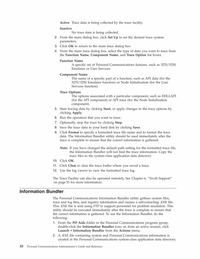
Active Trace data is being collected by the trace facility.
InactiveNo trace data is being collected.
2. From the main dialog box, click Set Up to set the desired trace systemparameters.
3. Click OK to return to the main trace dialog box.4. From the main trace dialog box, select the type of data you want to trace from
the Function Name, Component Name, and Trace Option list boxes.
Function NameA specific set of Personal Communications features, such as 3270/5250Emulator or User Services.
Component NameThe name of a specific part of a function, such as API data (for the3270/5250 Emulator function) or Node Initialization (for the UserServices function).
Trace OptionsThe options associated with a particular component, such as EHLLAPI(for the API component) or API trace (for the Node Initializationcomponent).
5. Start tracing data by clicking Start, or apply changes to the trace options byclicking Apply.
6. Run the operation that you want to trace.7. Optionally, stop the trace by clicking Stop.8. Save the trace data to your hard disk by clicking Save.9. Click Format to specify a formatted trace file name and to format the trace
data. The Information Bundler utility should be used immediately after thetrace is complete to ensure that the correct information is gathered.
Note: If you have changed the default path setting for the formatted trace file,the Information Bundler will not find the trace information. Copy thetrace files to the system-class application data directory.
10. Click OK.11. Click Clear to clear the trace buffer where you saved a trace.12. Use the log viewer to view the formatted trace log.
The Trace Facility can also be operated remotely. See Chapter 6, “Tivoli Support”on page 53 for more information.
Information BundlerThe Personal Communications Information Bundler utility gathers system files,trace and log files, and registry information and creates a self-extracting .EXE file.This .EXE file is sent using FTP to support personnel for problem resolution. Thisutility should be executed immediately after the trace is complete to ensure thatthe correct information is gathered. To use the Information Bundler, do thefollowing:1. From the PD Aids folder in the Personal Communications program group,
double-click the Information Bundler icon; or, from an active session, clickLaunch → Information Bundler from the Actions menu.
2. A .EXE file containing system and Personal Communications information iscreated in the Personal Communications system-class application data directory.
10 Personal Communications Administrator’s Guide and Reference

By default this file is called X12345.EXE. Refer to the installation documentationfor the location of the system-class application data directory for each Windowsoperating system.
Internet ServiceThe Internet Service utility enables you to send the .EXE file containing diagnosticdata collected by the Information Bundler to an FTP server. This utility will notwork unless TCP/IP is configured and you have a direct connection to the internet.To use Internet Service:1. Double-click the Internet Service icon located in the Personal Communications
program group; or, from an active session, click Actions → Launch → InternetService.The Internet Service window contains four data fields that must have validvalues before you can submit your problem report.
2. Verify that the FTP Address field contains the default addresstestcase.software.ibm.com. This is the service anonymous FTP server.
3. Type your e-mail address in the field provided.4. In the Problem Determination Filename field, type the file name and path of
the .EXE file created with the Information Bundler. This file is located in thePersonal Communications installation directory.
5. In the PMR Number field, type the PMR number that you received as a resultof contacting IBM support personnel.
6. When all fields in the window have been filled with valid values, clickTransmit to submit your problem determination information.
Checking for APARs and CSDsThe Product Update Tool allows you to manage CSDs (Corrective ServiceDistributions) and APARs (authorized program analysis reports) for PersonalCommunications. Authorized users also can use the Product Update Tool todownload, test, and commit APARs. Authorized Program Analysis Reports(APARs) are single module product fixes for Personal Communications, whileCSDs are full Personal Communications product updates. You must be connectedto the Internet in order to test or commit APARs.
The Product Update Tool uses .vbs files to download the correct APAR package, sothe Windows Scripting Host Service must be running on the machine beingupdated.
To access the Product Update Tool:1. Select Administrative and PD Aids from the Personal Communications start
menu.2. Click Product Update Tool.3. Click Connection Configuration to change connection and proxy options.
Note: If you have difficulty using the Product Update Tool on Windows 95systems, you may have to test an APAR or check for CSDs using anotherplatform. Refer to the Personal Communications Readme file for the latestinformation.
The following are the major functions available via the Product Update Tool.v “Test an APAR” on page 13
Chapter 2. Problem Analysis 11
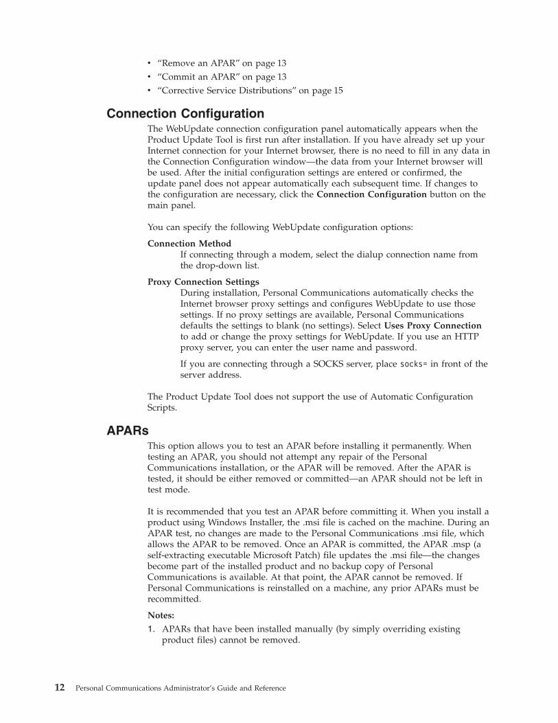
v “Remove an APAR” on page 13v “Commit an APAR” on page 13v “Corrective Service Distributions” on page 15
Connection ConfigurationThe WebUpdate connection configuration panel automatically appears when theProduct Update Tool is first run after installation. If you have already set up yourInternet connection for your Internet browser, there is no need to fill in any data inthe Connection Configuration window—the data from your Internet browser willbe used. After the initial configuration settings are entered or confirmed, theupdate panel does not appear automatically each subsequent time. If changes tothe configuration are necessary, click the Connection Configuration button on themain panel.
You can specify the following WebUpdate configuration options:
Connection MethodIf connecting through a modem, select the dialup connection name fromthe drop-down list.
Proxy Connection SettingsDuring installation, Personal Communications automatically checks theInternet browser proxy settings and configures WebUpdate to use thosesettings. If no proxy settings are available, Personal Communicationsdefaults the settings to blank (no settings). Select Uses Proxy Connectionto add or change the proxy settings for WebUpdate. If you use an HTTPproxy server, you can enter the user name and password.
If you are connecting through a SOCKS server, place socks= in front of theserver address.
The Product Update Tool does not support the use of Automatic ConfigurationScripts.
APARsThis option allows you to test an APAR before installing it permanently. Whentesting an APAR, you should not attempt any repair of the PersonalCommunications installation, or the APAR will be removed. After the APAR istested, it should be either removed or committed—an APAR should not be left intest mode.
It is recommended that you test an APAR before committing it. When you install aproduct using Windows Installer, the .msi file is cached on the machine. During anAPAR test, no changes are made to the Personal Communications .msi file, whichallows the APAR to be removed. Once an APAR is committed, the APAR .msp (aself-extracting executable Microsoft Patch) file updates the .msi file—the changesbecome part of the installed product and no backup copy of PersonalCommunications is available. At that point, the APAR cannot be removed. IfPersonal Communications is reinstalled on a machine, any prior APARs must berecommitted.
Notes:
1. APARs that have been installed manually (by simply overriding existingproduct files) cannot be removed.
12 Personal Communications Administrator’s Guide and Reference
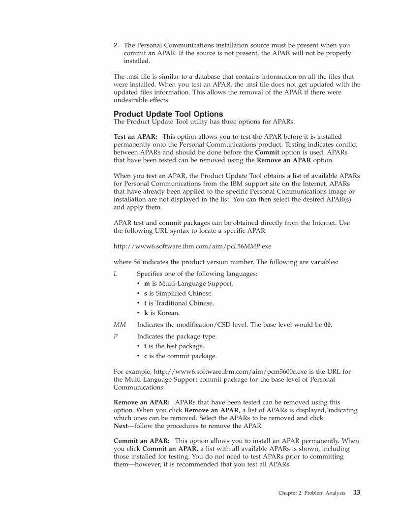
2. The Personal Communications installation source must be present when youcommit an APAR. If the source is not present, the APAR will not be properlyinstalled.
The .msi file is similar to a database that contains information on all the files thatwere installed. When you test an APAR, the .msi file does not get updated with theupdated files information. This allows the removal of the APAR if there wereundesirable effects.
Product Update Tool OptionsThe Product Update Tool utility has three options for APARs.
Test an APAR: This option allows you to test the APAR before it is installedpermanently onto the Personal Communications product. Testing indicates conflictbetween APARs and should be done before the Commit option is used. APARsthat have been tested can be removed using the Remove an APAR option.
When you test an APAR, the Product Update Tool obtains a list of available APARsfor Personal Communications from the IBM support site on the Internet. APARsthat have already been applied to the specific Personal Communications image orinstallation are not displayed in the list. You can then select the desired APAR(s)and apply them.
APAR test and commit packages can be obtained directly from the Internet. Usethe following URL syntax to locate a specific APAR:
http://www6.software.ibm.com/aim/pcL56MMP.exe
where 56 indicates the product version number. The following are variables:
L Specifies one of the following languages:v m is Multi-Language Support.v s is Simplified Chinese.v t is Traditional Chinese.v k is Korean.
MM Indicates the modification/CSD level. The base level would be 00.
P Indicates the package type.v t is the test package.v c is the commit package.
For example, http://www6.software.ibm.com/aim/pcm5600c.exe is the URL forthe Multi-Language Support commit package for the base level of PersonalCommunications.
Remove an APAR: APARs that have been tested can be removed using thisoption. When you click Remove an APAR, a list of APARs is displayed, indicatingwhich ones can be removed. Select the APARs to be removed and clickNext—follow the procedures to remove the APAR.
Commit an APAR: This option allows you to install an APAR permanently. Whenyou click Commit an APAR, a list with all available APARs is shown, includingthose installed for testing. You do not need to test APARs prior to committingthem—however, it is recommended that you test all APARs.
Chapter 2. Problem Analysis 13

During the commit process, a window displays a list of active tasks that mightinterfere with the commit process (for example, active Personal Communicationssessions)—the Product Update Tool may be one of the listed tasks. If so, close thelisted tasks, including the Product Update Tool, and click Retry in the Installerdialog to complete the process. You may also click Cancel to terminate the updateprocess. If you choose Ignore, you are more likely to be required to reboot in orderfor locked files to be updated.
The commit process requires access to the original installation files. If you installedPersonal Communications from the product CD, you must have the CD in theCD-ROM drive; if you installed Personal Communications off the network, youmust be connected to the network. If the source is not present, you must providethe location of the source files.
When you choose to commit an APAR, the APAR .msp file is downloaded andexecuted. Once you have selected what APARs you would like to commit, thecorresponding .msp file is launched silently. Since the changes are permanent, nobackup copy is made. You can then distribute one or more .msp files across thenetwork.
If the operating system is Windows 95, 98, or Me, the .msp file is saved in
X:\<drive>\Application Data\IBM\PersonalCommunications\APARs\[APAR Name]
where X:\<drive> is the directory in which the operating system resides. ForWindows NT, the .msp file is saved in
X:\<drive>\Profiles\All Users\Application Data\IBM\PersonalCommunications\APARs\[APAR Name]
For Windows 2000 and XP, the .msp file is saved in
X:\Documents and Settings\All Users\Application Data\IBM\PersonalCommunications\APARs\[APAR Name]
Note: After an APAR has been installed for testing or committed, the filepcommaparinfo.txt is created in the above application data directories. Thisfile contains a list of the APARs that have been installed as well as theirstatus (tested or committed). This file must not be edited or moved, becauseit is essential for the proper tracking of APARs.
If you have a .msp file, you can manually commit the maintenance to othersystems by using the following msiexec.exe command:msiexec.exe /p APAR.msp REINSTALLMODE=em
where APAR is the name of the APAR file.
Administrative InstallationYou can apply APARs to an install image by using the msiexec.exe parameter /pAPAR.msp, where APAR is the name of the APAR. This parameter may be used inconjunction with the /a parameter, in order to commit an APAR to anadministrative installation. The command line syntax is as follows:msiexec.exe /a "[absolute path to product .msi file]" /p "[absolute
path to .msp file]" REINSTALLMODE=em
14 Personal Communications Administrator’s Guide and Reference

Refer to the CD-ROM Guide to Installation for more information aboutadministrative installation and command line parameters. For more informationabout the REINSTALLMODE property, refer to the Microsoft Developer Networkat http://msdn.microsoft.com.
You should always test an APAR on an administrative installation before pushingthe new image and/or the APAR to other machines. The administrative installationon which APARs are tested and the administrative install image should always besynchronized.
Interim Service BuildsAn Interim Service Build (ISB) is a cumulative APAR package containing allcurrently available APAR fixes. ISBs are tested to ensure that the included APARsfunction well together. You can obtain ISBs using the APAR commit option in theProduct Update Tool. or by downloading the .msp file.
When you check for APARs, any available ISBs are also displayed. Thecorresponding .msp file is located in the same application data directory as APARs,with the specific ISB name. You may then be prompted to reboot the system.
To download ISB files, go to the Corrective Service Distribution site—you will finda link to the latest ISB, a list of included APARs, and installation instructions.
Corrective Service DistributionsCSDs are packages containing a bundle of APARs and possibly new productoptions and improvements. For Personal Communications, new CSDs arecumulative. To check for CSDs, click Check for CSDs in the Product Update Tool.
Installing a CSD is similar to a reinstallation of the product (removing old productfiles and installing new files); therefore, there is no test and commit processavailable for CSDs. To remove a CSD, your only option is to uninstall the currentPersonal Communications product level, then reinstall the prior level.
You can only obtain CSDs if you have purchased a full version of the product. Thisis validated by entering a service key, which is included in the original package ofPersonal Communications. When you check for CSDs, your Internet browser opensto the CSD site, where you will prompted to enter your registration data andservice key. Once registration is complete and the service key is entered, you canselect the product, version and language for which you need the CSD update.
Note: A CSD file is usually larger than 100 MB.
Detect and RepairThe Help → Detect and Repair operation performs a check on the installedPersonal Communications files to determine if the installation has been damaged.A subsequent repair is performed, if necessary. Users must be authorized in theSystem Policy to use this feature. The user may be prompted for the installationimage.
The Restore my shortcuts option will restore the original shortcuts. If the shortcutshave been modified since the original Personal Communications installation, youmay want to keep shortcuts intact; in that case, do not choose this option.
Personal Communications Detect and Repair performs the following operations:
Chapter 2. Problem Analysis 15

v Reinstalls a file if it is missing or corrupt, or if it is an older version.v Rewrites all registry settings for the application in the LOCAL_MACHINE
section of the registry.v Rewrites all registry settings for the application in the CURRENT_USER section
of the registry.v Reinstalls all shortcuts (optional).
Alternatively, Windows Installer performs the following operations:v Reinstalls a file if it is missing or corrupt, or if it is an older version. Windows
Installer does not check files for corruptionv Rewrites all registry settings for the application in the LOCAL_MACHINE
section of the registry.v Rewrites all registry settings for the application in the CURRENT_USER section
of the registry.v Reinstalls all shortcuts. This function is not optional in Windows Installer.
16 Personal Communications Administrator’s Guide and Reference

Part 2. Advanced Configuration, Management, and Operations
© Copyright IBM Corp. 1989, 2002 17

18 Personal Communications Administrator’s Guide and Reference
Chapter 3. Advanced Configuration
This chapter describes facilities useful for deploying Personal Communications inlarge networks. Some of these facilities are handled by features of PersonalCommunications itself, while others are provided by external products, augmentedwith facilities provided by Personal Communications.
Configuration FilesThe following sections describe the advanced configurations that you can makewith the built-in files of Personal Communications. Advanced configurationsenable you to easily configure and distribute common keywords and parameters toyour client base, and include the following:v Initial Configuration Definitionsv Configuration with Template and Update Files
Initial Configuration DefinitionsPersonal Communications enables network administrators to create an initialconfiguration definitions file that contains common configuration definitions fortheir clients. By using an initial configurations file, the administrator can distributepreconfigured definitions and have them automatically preloaded whenever a newconfiguration is created on a client.
The first step is to create a configuration using SNA node configuration, Start orConfigure Sessions, or an ASCII editor. For detailed information on configuringsessions, refer to Quick Beginnings.
After you create the configurations file, rename the file to the appropriate reservedname. For SNA node configuration files (*.ACG), the file name is PCSINIT.AC$.For workstation profiles (*.WS), the file name is PCSINIT.WS$. For emulatorconfigurations using SNA communication, you should use both a PCSINIT.WS$and a PCSINIT.AC$ file.
After you rename the files, they can be distributed to client workstations. Put thefiles in the configuration files directory. The definitions in the files will bepreloaded whenever a user creates a new configuration.
Note: The initial configuration file does not override parameter defaults for newdefinitions in new configurations, but preloads complete definitions intonew configurations. Users can modify these definitions to get customparameter values; however, the original initial configuration file remainsunchanged.
Configuration File and Emulator Profile DirectoriesThe default directory for configuration files is specified during installation.Configuration files can be used for all users or a specific user. Refer to theCD-ROM Guide to Installation for details on specifying the initial default directory.
By default, Personal Communications searches for emulator profiles in theconfiguration files directory. You can use the User Preference Manager utility toindicate a different location for profiles.
© Copyright IBM Corp. 1989, 2002 19
Using Template and Update FilesWhen creating configurations for a large number of clients to implement, you cancreate a template configuration file that represents the common configurationelements for all clients. Using an update file with only those changes necessary foreach client, you can distribute the template and update file and merge the two tocreate the target configuration.
The Personal Communications Server template and update files enable you tocreate or modify a configuration using an ASCII editor. You can configure all of thePersonal Communications configuration keywords and parameters with updatefiles. Both the template and update files have the same format as PersonalCommunications configuration (.ACG) files.
Template files can ease the mass distribution of configurations to remote clients. Atemplate file can specify the keywords which are common to several clients. Forexample, if you have multiple clients to configure as SNA clients, many of thekeywords will be identical. You can create a template configuration file that reflectsthose common keywords.
You can use update files to add, modify, or delete keywords in a template file. Theoriginal template configuration file is left unchanged. An update file is merged intoa template file by specifying the INCLUDE keyword at the end of the template file.For example, if an update file is named myconfig.chg, the last line of the templatefile that will use the update file is INCLUDE=myconfig.chg. When the template fileand the update file are merged, you can give the resulting configuration file aname with the .ACG extension that distinguishes it from other .ACG files.
When you create configurations using template and update files, the verificationutility searches directories in the following order:1. The local directory where the verification utility is being invoked2. The system-class application data directory
To ensure that the verification utility can locate the template and update files, youshould store them in the system-class application data directory, which is alsowhere the configuration (.ACG) files are stored.
Key FieldsThe key field is the parameter in a keyword that names the keyword and uniquelyidentifies it from other keywords of the same type.
Some keywords do not have key fields because they can only be specified once ina configuration file. An example of a keyword that can only be specified once isthe NODE keyword.
Adding Keywords to a Template FileWhen using an update file to add a new keyword definition, you must provide theentire keyword. The key field must be provided along with a unique value. If anysubfields are omitted from the keyword, the defaults for those fields are used. Forexample, to add a MODE keyword to the configuration, the update file mightcontain the following keyword:MODE=(
MODE_NAME=MYMODECOS_NAME=#INTERCRYPTOGRAPHY=NONEDEFAULT_RU_SIZE=1
20 Personal Communications Administrator’s Guide and Reference

MAX_NEGOTIABLE_SESSION_LIMIT=128MAX_RU_SIZE_UPPER_BOUND=4096MIN_CONWINNERS_SOURCE=15
)
The content of the update file assumes that a MODE keyword with the parameterof MODE_NAME=MYMODE does not exist in the template. If it does, theparameters will be updated with the values provided in the update file.
If the MODE_NAME parameter is omitted from the update file, an error will occurduring the configuration verification because the MODE_NAME parameter cannotbe uniquely identified. Not all parameters available for the MODE keyword arespecified in the update file. The remaining parameters use the defaults as specifiedin the Configuration File Reference. The resulting addition to the configuration willlook like this:MODE=(
MODE_NAME=MYMODEAUTO_ACT=0COMPRESSION=PROHIBITEDCOS_NAME=#INTERCRYPTOGRAPHY=NONEDEFAULT_RU_SIZE=1MAX_NEGOTIABLE_SESSION_LIMIT=128MAX_RU_SIZE_UPPER_BOUND=4096MIN_CONWINNERS_SOURCE=15PLU_MODE_SESSION_LIMIT=32RECEIVE_PACING_WINDOW=1
)
Modifying a Keyword in a Template FileWhen using the update file to modify an existing keyword definition, the originalkeyword should exist in the template file. If it does not exist in the template file,the update file adds an entry to the new configuration. You must specify the keyparameter in the update file to identify the target keyword. Only those parametersspecified in the update file keyword are updated in the template file’s keyword.Parameters not specified in the update file are left unchanged. For example, if thefollowing MODE keyword is in the template file:MODE=(
MODE_NAME=#INTERAUTO_ACT=0COMPRESSION=PROHIBITEDCOS_NAME=#INTERCRYPTOGRAPHY=NONEDEFAULT_RU_SIZE=1MAX_NEGOTIABLE_SESSION_LIMIT=256MAX_RU_SIZE_UPPER_BOUND=4096MIN_CONWINNERS_SOURCE=128PLU_MODE_SESSION_LIMIT=256RECEIVE_PACING_WINDOW=20
)
and the following keyword is specified in the update file:MODE=(
MODE_NAME=#INTERAUTO_ACT=10
)
the resulting configuration would have the following MODE keyword definition:MODE=(
MODE_NAME=#INTERAUTO_ACT=10
Chapter 3. Advanced Configuration 21

COMPRESSION=PROHIBITEDCOS_NAME=#INTERCRYPTOGRAPHY=NONEDEFAULT_RU_SIZE=1MAX_NEGOTIABLE_SESSION_LIMIT=256MAX_RU_SIZE_UPPER_BOUND=4096MIN_CONWINNERS_SOURCE=128PLU_MODE_SESSION_LIMIT=256RECEIVE_PACING_WINDOW=20
)
Deleting a Keyword from a Template FileWhen using the update file to delete a keyword from the template, you mustspecify the key parameter and value that identify the keyword, along with thekeyword DELETE. For example, if the template file specifies the followingkeyword:MODE=(
MODE_NAME=#INTERAUTO_ACT=0COMPRESSION=PROHIBITEDCOS_NAME=#INTERCRYPTOGRAPHY=NONEDEFAULT_RU_SIZE=1MAX_NEGOTIABLE_SESSION_LIMIT=256MAX_RU_SIZE_UPPER_BOUND=4096MIN_CONWINNERS_SOURCE=128PLU_MODE_SESSION_LIMIT=256RECEIVE_PACING_WINDOW=20
)
and the response file contains the following keyword:MODE=(
MODE_NAME=#INTERDELETE
)
the resulting configuration does not contain the #INTER mode definition.
The DELETE keyword can appear after a parameter=value specification or on a lineby itself, either preceding or following the parameter. For example, the followinguses of the DELETE keyword are valid:MODE=(
MODE_NAME=#INTERDELETE
)MODE=(
DELETEMODE_NAME=#INTER
)
The DELETE keyword cannot appear in front of a parameter=value specification onthe same line. For example, the following uses of the DELETE keyword are notvalid:MODE=(
DELETE MODE_NAME=#INTER)
MODE=(MODE_NAME=#INTER DELETE
)
22 Personal Communications Administrator’s Guide and Reference
To delete all keywords of a particular type, or to delete one keyword that does nothave a key field, only the keyword and the DELETE keyword are necessary. Forexample,MODE=(
DELETE)
Note: Not all keywords can be deleted; only those which are not listed as requiredcan be deleted—refer to the Configuration File Reference for details.
Applying Updates to Configuration FilesTo update or change an existing SNA configuration file using an update file, do thefollowing:1. Using a text editor, create an update file that contains keywords to be added,
deleted, or changed in an existing SNA node configuration file.2. Add an include statement at the bottom of the existing SNA node configuration
or template indicating the name of the update file.3. Invoke the SNA Configuration Verification utility by typing the following on
the command line:vacgcon config.acg newconfig.chg
config.acgThe existing configuration file
newconfig.chgThe new configuration file
You must remove the include statement to reuse your template as aconfiguration file.
Note: When an update file does not contain a complete, usable configuration, it isrecommended that you use an extension other than .ACG.
Automatic Device Name Generation (5250 Only)The Telnet 5250 client function can generate a new and non-arbitrary DEViceNAME (DEVNAME) for a session without requiring per-session profile (*.WS)customization or a user exit.
You can use keywords and special characters in the WorkStationID (WID) field (inthe [5250] stanza of the Workstation profile) to cause some or all of the followinginformation to be substituted into the DEVice NAME value that is sent to theTN5250 server:v Computer name or user namev Short session IDv Session type IDv Collision avoidance ID
When specified, the Collision Avoidance ID enables the generation of a newDEVice NAME if the Telnet server rejects a submitted name (which can occurwhen the old name is already in use on the AS/400). The ability to have a varietyof names generated allows multiple sessions to the same AS/400 from one or moreclients using just one WorkStation Profile (.WS) file. The definition of the existing.WS file parameter WorkStationID in the [5250] stanza is extended to accomplishthis.
Chapter 3. Advanced Configuration 23
Substitution CharactersYou can use special substitution characters in the WID field to control theplacement of the generated information into the DEVNAME field. One substitutioncharacter is used in the WID for each generated character. This reserves space inthe DEVNAME for each generated character and indicates where each generatedcharacter is to be placed. The three special substitution characters are:
Short Session ID(value range: A–Z) The special character signifying this in the WID is theasterisk (*).
Example:If the WorkstationID is configured as 123* and the short ID of the firstsession is A, then the device names generated for the first three sessionswill be 123A, 123B, and 123C.
Session Type ID(possible values: S for diSplay or P for Printer) The special charactersignifying this in the WID is the percent sign (%).
Example: If the Workstation ID is configured as %123* and the session typeis Printer, then the first three device names generated would beP123A, P123B, and P123C.
Collision Avoidance ID(value range: 1–9, A–Z) The Collision Avoidance ID (CAID) is used by thedevice name collision (DNC) function (see “Device Name CollisionProcessing” on page 25) to generate a new DEVice NAME when the oldname is rejected by the Telnet server as already being in use. The specialcharacter signifying this in the WID is the equals sign (=).
Example: If the Workstation ID is configured as %ABC=, the session type isDisplay, and the device name SABC1 is already in use on theAS/400, then the first generated device name (SABC1) will berejected by the server, but the second name (SABC2) will beaccepted.
Client Naming FunctionIf you specify a Client Naming (CN) substitution keyword in the Workstation ID(WID) field, then an external name is retrieved and used when generating theDEVice NAME.
The CN keywords are prefixed with the ampersand character (&), followed by afive character identifier. Two keywords are supported:
&COMPNWindows COMPuter Name for the client
&USERNUSER Name specified during logon to the Windows computer where theemulator executes
A name whose length exceeds the space remaining in the 10 character longDEVNAME field will have that excess trimmed from the left side by default.Excess characters can alternatively be trimmed from the right side by prefixing theCN keyword with a plus sign (+) character (for example, +&COMPN).
24 Personal Communications Administrator’s Guide and Reference
Notes:
1. If the specified name cannot be obtained, then the message Unable to get thelocal "x" name (where ″x″ is COMPN or USERN) is displayed in the statusbar.
2. If a client naming keyword is specified in the WID, then characters other thanthose defined for this feature are ignored.
3. A numeric character in the first position of a DEVNAME is invalid, and may beconverted by the AS/400 to the pound (or number) character (#).
Example A: If the Workstation ID is &COMPN* and the name of the local computer isclientaccess1, then the device names generated for the first threesessions would be ntaccess1A, ntaccess1B, and ntaccess1C.
Example B: If the Workstation ID is +&COMPN*% and the name of the USER logonfor the local computer is clientaccess1, then the device namesgenerated for the first three sessions would be clientaccA, clientaccB,and clientaccC.
Device Name Collision ProcessingDevice name collision occurs when a Telnet client sends the Telnet server a virtualdevice name, but that device name is already in use on the server. When thisoccurs, the Telnet server sends a request to the client asking it to send a differentDEVNAME.
Device name collision (DNC) processing handles requests from the server for adifferent DEVNAME. If the collision avoidance ID (CAID) substitution character ispresent in the WID, the CAID is incremented and sent as part of the newDEVNAME to the server.
If the server requests a different DEVNAME and the CAID is not present in theWID, then the error message Device Name "x" is invalid or already in use onthe server is displayed on the status bar and the session is disconnected.
Support for Systems PoliciesAdministrators can set up centrally controlled sets of policies for use by PersonalCommunications workstation users; these policies can restrict access to certainfunctions.
See Chapter 7, “System Policy Support” on page 67 for further information.
Support for Management by Tivoli®
Personal Communications provides facilities to integrate with the TivoliEnterprise™ Management set of products, thus allowing access to many productfeatures from management consoles.
See Chapter 6, “Tivoli Support” on page 53 for further information.
Commands for Emulator FunctionsPersonal Communications provides the following commands for managingPersonal Communications sessions. These commands can be used to facilitateremote access (for example, by the Tivoli console):
Chapter 3. Advanced Configuration 25

PCOMSTRTStart a Personal Communications session
PCOMSTOPStop a Personal Communications session
PCOMQRYQuery Personal Communications sessions
Start a Personal Communications SessionThe command PCOMSTRT has the following parameters:
/p Name of workstation profile to start (required). The syntax is/p=workstation-profile. You can specify the workstation profile as either thepath (drive, directory, and file name) or just the file name, in which casethe location of the workstation profile file is the user-class application datadirectory.
/s Session letter of the session to start. The syntax is /s=session-letter. This isoptional. If omitted, the first available session letter is used.
/w Session window startup state. The syntax is /w={0|1|2|3}.
0 Hidden
1 Normal (default)
2 Minimized
3 Maximized
/q Quiet mode. In quiet mode, PCOMSTRT does not write any messages tostdout.
/nowaitDo not wait for session to start. The /nowait option tells PCOMSTRT tocomplete execution without waiting until the emulator session is started.There is no /wait option; the default is to wait until the session is started.
/c Convert output to Windows code page for output. The /c option isintended to be used when the Tivoli IBMPCOMM Plus module taskinvokes the PCOMSTRT program. It is not intended to be used when auser starts the program from an MS-DOS prompt.
/? Displays help information.
Returns: DOS Error level is set for use when this command is invoked by aprogram. When the command is directly entered, a message indicating the sessionis starting is displayed.
Stop a Personal Communications SessionThe command PCOMSTOP has the following parameters:
/s Session letter of session to stop. The syntax is /s=session-letter. This isoptional. If omitted, the first available session letter is used.
/all Stops all sessions
/q Quiet mode. In quiet mode, PCOMSTOP does not write any messages tostdout.
Reviewers:
Removed /nowait option, per defect 76965.
26 Personal Communications Administrator’s Guide and Reference

/c Convert output to Windows code page for output. The /c option isintended to be used when the Tivoli IBMPCOMM Plus module taskinvokes the PCOMSTOP program. It is not intended to be used when auser starts the program from an MS-DOS prompt.
/? Displays help information.
Returns: DOS Error level is set for use when this command is invoked by aprogram. When the command is directly entered, a message is displayed indicatingthe session is stopping.
Query Personal Communications SessionsThe command PCOMQRY has the following parameters:
/s Session letter of session to query, The syntax is /s=session-letter. This isoptional. If omitted, the first available session letter is used.
/all Queries all sessions.
/q Quiet mode. In quiet mode, PCOMQRY does not write any messages tostdout.
/nowaitDo not wait for session to query. The /nowait option tells PCOMQRY tocomplete execution without waiting until the emulator session is queried.There is no /wait option; the default is to wait until the session is queried.
/c Convert output to Windows code page for output. The /c option isintended to be used when the Tivoli IBMPCOMM Plus module taskinvokes the PCOMQRY program. It is not intended to be used when a userstarts the program from an MS-DOS prompt.
/? Displays help information.
Chapter 3. Advanced Configuration 27

28 Personal Communications Administrator’s Guide and Reference

Chapter 4. Configuring Multiple Links
Many customers must attach to multiple AS/400 and S/390® mainframe systems.Personal Communications allows this type of configuration. The following sectionsexplain how to do this.
Note: You do not need to read this section if you want to create multiple sessionson the same host.
Configuring a Second 3270 Emulation Link
RecommendationIf you want a second SNA connection (link) to run concurrently, we stronglyrecommend that you configure it in the same .ACG file as the first one; thiswill avoid any possible conflict of settings.
Perform the following steps to configure a second 3270 emulation link. You canmake the configuration even if the first link is active.1. Double-click the Start or Configure Sessions icon to start a new session; or
click Configure from the Communication menu.2. Choose the host, interface, and attachment type, as usual.3. Configure the session parameters, then click Configure Link.4. In the Configure Local System panel, check that the default .ACG file is the
one in which you saved the configuration for the first link. If not, clickExisting and choose the correct file from the list.
5. Check that the settings for the PC Location Name are correct. Click Next.6. The LAN Device Connection panel appears. Under Device Selection, be sure
that the device used for the first link is displayed. Under ConnectionSelection, select New Connection. Notice that the connection name haschanged to show a new link name. Click Next.
7. The Configure LAN Connection panel is displayed. The Destination Addressfield will show 400000000000. Enter the Destination Address for the secondlink, and change the additional parameters if needed.
8. Click Advanced.9. The Advanced dialog panel shows the default values for block ID and PU ID.
Change them as necessary to the values for the second link. Click OK.
10. Click Next, then Finish, and save the .ACG file (replace the existing file).Then click OK until you return to the session window. If you have doneeverything correctly, and if the gateway or controller is running, you shouldget a connection.
You can add further 3270 links in the same way.
Configuring a Second 5250 Emulation LinkThe steps you should follow to configure a second 5250 emulation link are almostthe same as for 3270. You can make the configuration even if the first link is active.
© Copyright IBM Corp. 1989, 2002 29
1. Double-click the Start or Configure Sessions icon to start a new session; orclick Configure from the Communication menu.
2. Choose the host, interface, and attachment type, as usual.3. Configure the session parameters, then click Configure Link.
4. In the Configure Local System panel, check that the default .ACG file is the onein which you saved the configuration for the first link. If not, click Existing andchoose the correct file from the list.
5. Check that the settings for the first link are correct. Click Next.
6. The Configure Logical Connection panel appears, showing the settings for thefirst link. If you are going to connect to a different AS/400, change the SystemLocation Name. Click Next.
7. The Configure LAN Connection panel appears. If the Link Station Name hasnot changed, change it.
8. Change the Destination Address (and the other parameters if necessary). If youwant to change the Local SAP number or the Receive Buffer Count, (which isunlikely), click Advanced. If not, click Next, then Finish, and save the .ACGfile (replace the existing file), then click OK until you return to the sessionwindow.
You can add further 5250 links in the same way.
Configuring a Second Link of a Different KindThe procedure for configuring other links is similar to those for the configurationsfor 3270 and 5250 link configurations. This procedure applies whether you aregoing to configure two (or more) links that use the same connection type, or linksthat use different connection types. In this example, assume that you have alreadyconfigured a 3270 connection and now want to add a 5250 connection. As before,you can make the configuration even if the first link is active.1. Double-click the Start or Configure Sessions icon to start a new session; or
click Configure from the Communication menu.2. Choose AS/400, the LAN interface and the IEEE 802.2 attachment type.3. Configure the session parameters, then click Configure Link.
4. In the Configure Local System panel, check that the default .ACG file is the onein which you saved the configuration for the 3270 link. If not, click Existingand choose the correct file from the list. Notice that the PC Location Name isalready there. Click Next.
5. The Configure Logical Connection panel appears. Enter the System LocationName and click Next.
6. Notice that the Link Station Name has changed. Enter the Destination Addressof the AS/400. Click Next, then Finish, and save the .ACG file (replace theexisting file); then click OK until you return to the session window.
Configuring to Perform 3270 and 5250 Emulation to Multiple HostsTo configure Personal Communications to perform 3270 and 5250 emulation tomultiple hosts:1. Click Actions → Launch → SNA Node Configuration of your active session; or
click SNA Node Configuration from the Program → IBM PersonalCommunications folder on the Windows Start menu.
2. Configure the node information:a. Click Configure Node from the list of Configuration options.
30 Personal Communications Administrator’s Guide and Reference
b. Click New.c. In the Fully qualified CP name field, enter the Network ID and CP name
that is defined for you on the AS/400 (APPN.TEST, for example).Note: If the AS/400 is performing automatic configuration, the value youenter here is ignored. However, it is still necessary to enter a value in thefield to close the panel.
d. Click OK.3. Configure the device information:
a. Click Configure Devices from the list of Configuration options.
Note: In Windows 2000 and XP, the dialog displays the device adaptersthat are installed and indicates whether each adapter is enabled ordisabled.
b. Click LAN from the list of available DLCs.Note: These instructions are based on the LAN DLC; the field names andtabs might be slightly different if you are configuring another type of DLC.
c. Click New.d. Specify the adapter number for the connection.e. Click OK.
4. Configure the connection information:a. Click Configure Connections from the list of Configuration options.b. Click LAN from the list of available DLCs.c. Click New.d. Enter the Link station name (default is LINK0000) and click the device (for
example, LANX_04) that you defined in step 3 from the Device Name list.This link will be defined for the 5250 session to the AS/400.
e. Enter the LAN destination address of the AS/400.f. Click the Advanced tab.g. Verify that Activate at startup is checked.h. Verify that APPN support is checked.i. If you plan to use 3270 passthrough on this connection, click Solicit SSCP
sessions.j. Click OK to save the information.
5. Configure the second link for the 3270 session:a. Click New.b. Enter the Link station name (default is LINK0001) and select the same
device you used to define the 5250 session (for example, LANX_04). Thislink will be defined for the 3270 session to the host.
c. Enter the LAN destination address of the host.d. Click the Advanced tab.e. Verify that Activate at startup is checked.f. Verify that APPN support is checked.g. Click Solicit SSCP sessions.h. In the Local Node ID field, enter the Block ID and Physical Unit ID that
identifies the device.i. Click the Adjacent Node tab.j. Click HOST-XID3 from the list of Adjacent CP types.k. Click OK.
Chapter 4. Configuring Multiple Links 31

6. Configure the Partner LU 6.2 information:a. Click New.b. Enter the Partner LU name, such as APPN.S101010. This is the name of the
AS/400; this information can be obtained by running a DSPNETA on theAS/400.
c. Click OK.7. Save the configuration information:
a. On the SNA Node Configuration window, click Save As from the Filemenu.
b. Enter a file name with a .ACG file extension, such as TEST.ACG. Click Yesto make this configuration the default.
c. Click Exit on the File menu.8. Start the 5250 emulator session:
a. Click Start or Configure Sessions from the Program → IBM PersonalCommunications folder of the Windows Start menu.
b. Click the AS/400 host, the LAN interface, and the IEEE 802.2 attachment.c. Click Configure.d. Click Configure Link.e. Click Existing.f. Click the configuration you saved in step 7 from the list and click Open.g. Click Next.h. Verify that the System location name matches the name you specified in
step 6. Click Next.i. In the Device name field, select the device name you defined in step 3.
Click Next.j. In the Link station name field, select the name you defined in step 4, such
as LINK0000. Click Next.k. Click Finish.l. Click Save and then click Yes to overwrite the existing file.m. Click OK to close the Customize Communication - 5250 Host window and
then click OK to close the Customize Communication window and startthe 5250 session.
9. Save the workstation profile for the 5250 session:a. Click Save As from the File menu on the emulator window.b. Enter a file name with a .WS extension and click OK.c. If you want the ability to start this session separately, click Yes to create an
icon; otherwise, click No.d. Click OK.
10. Start the 3270 emulator session:a. Click Start or Configure Sessions from the Program → IBM Personal
Communications folder of the Windows Start menu.b. Click the S/390 host, the LAN interface, and the IEEE 802.2 attachment.c. Click Configure.d. Click Configure Link.e. Click Existing.f. Select the configuration you saved in step 7 from the list and click Open.g. Click Next.
32 Personal Communications Administrator’s Guide and Reference

h. In the Device name field, select the device name you defined in step 3.Click Next.
i. In the Link station name field, select the name you defined in step 5, suchas LINK0001.
j. Click Advanced.k. Deselect APPN support and click OK.l. Click Next.m. Click Finish.n. Click Save and then click Yes to overwrite the existing file.o. Click OK to close the Customize Communication - 3270 Host window and
then click OK to close the Customize Communication window and startthe 3270 session.
11. Save the workstation profile for the 3270 session:a. Click Save As from the File menu on the emulator window.b. Enter a file name with a .WS extension and click OK.c. If you want to start this session separately, click Yes to create an icon;
otherwise, click No.d. Click OK.
12. Create a batch file to start both the 5250 session and the 3270 session at thesame time:a. Close both running emulator sessions.b. Click Programs → IBM Personal Communications → Utilities → Multiple
Sessions from the Windows Start menu.c. From the list of workstation profile files, select the .WS file for the 5250
session (step 9). Click Add.d. From the list of workstation profile files, select the .WS file for the 3270
session (step 11). Click Add.e. Click Save As from the File menu and enter a file name with a .BCH
extension to save the batch file. Click OK.f. Click Yes. Verify that the folder is the DESKTOP and select both check boxes.
Click OK.g. Click Exit from the File menu.
13. To start the 5250 and 3270 emulator sessions together, double-click the BatchFile icon on your Desktop.
Chapter 4. Configuring Multiple Links 33

34 Personal Communications Administrator’s Guide and Reference
Chapter 5. Attachment Considerations and Adapter SetupInformation
This chapter describes factors you should consider when configuring PersonalCommunications for the following attachment types:v “COAX Attachment”v “LAN via IEEE 802.2 Attachment” on page 36v “TCP/IP Connection” on page 36v “SDLC MPA Attachment” on page 38v “IBM Global Network - SNA over Async Attachment” on page 39v “IBM Global Network Connection Attachment” on page 39v “Home3270 Attachment” on page 40v “3270 Attachment via the AS/400 System” on page 41v “IBM PC720 Modem Initialization (Japan Only)” on page 41v “3174 Peer Communications Support (LAN over Coax)” on page 41v “5250 Twinaxial Console” on page 42v “5250 Asynchronous Console” on page 43
This chapter also contains information about setting up communications adapters(for example, Coax, Twinax, MPA, SDLC, WAC). See the following topics:v “Adapter Setup Information” on page 44v “Twinax Adapters” on page 46v “IBM SDLC PCMCIA Adapter and Modem (Japan Only)” on page 48v “IBM PCI Multiprotocol Adapter” on page 49v “WAC Attachments” on page 50
Attachment Information
COAX AttachmentThis section describes factors you should consider when configuring PersonalCommunications with a coaxial attachment.
Note: The APPC and CPI-C APIs, provided with Personal Communications, do notsupport coaxial connections.
Avoiding Machine Check 207Patch the microcode of the 3174 control unit. The following list shows therelationship between 3174 control unit microcode levels and patch IDs:
Microcode Level Patch ID
S0503 PCA53D1
S0504 PCA53D2
A0503 PCA53D3
A0504 PCA53D4
B0200 PCA53D5
© Copyright IBM Corp. 1989, 2002 35

B0401 PCA53D6
B0402 PCA53D8
C0101 PCA53D7
In addition, if you have a 3174 with Configuration Support B or higher, you canset the following parameters:v 3174 customization Q126 digit 2=1 to change the COAX timeout from 50 to 100
microseconds.v 3174 customization Q125 digit 4=1 to set command chaining off.
RestrictionsWhen your workstation is configured to use a DFT attachment, the followingfunctions and capabilities of the IBM 3174 or 3274 Control Units are not supported:v Programmed symbols on attached workstationsv Attachment to port 0 on attached workstationsv Database operationsv 3270 Diagnostic Reset Dumpv Patch facility
Configuring a Non-Plug-and-Play Coax Adapter (ISA)See “Adapter Setup Information” on page 44 for more information on configuringIBM coax adapters.
LAN via IEEE 802.2 AttachmentFollowing is a description of preinstallation considerations for installing PersonalCommunications for use on a LAN. For more detailed information, refer to theIBM Local Area Network Technical Reference.
PIU SizeThis value is negotiated between your workstation and the host system, unlessXID=No is defined on the PU, or the Adjacent CP type has been changed toHost - XID0 in SNA Node Configuration. If this value is not negotiated, theMaximum PIU Size must match the MAXDATA value defined on the host system.
Receive Window CountThis value is negotiated between your workstation and the host system, unlessXID=No is defined on the PU, or the Adjacent CP type has been changed toHost - XID0 in SNA Node Configuration. If this value is not negotiated, theReceive Window Count must match the MAXOUT value defined on the host system.
Using a PCMCIA Token-Ring or Ethernet CardPersonal Communications supports the IBM Token-Ring and Ethernet credit cardadapters in the same way as it does the full-size adapters.
TCP/IP ConnectionThis section provides information, considerations, and restrictions for PersonalCommunications TCP/IP connections.
TCP/IP Protocol DriverYou must set up your Windows environment for the TCP/IP network. To verifythat the TCP/IP protocol is installed on your workstation, double-click Network inyour Control Panel and see if TCP/IP appears in the list of network components.Double-click TCP/IP to specify your IP address and other TCP/IP properties.
36 Personal Communications Administrator’s Guide and Reference

Screen SizeThe following four screen sizes are supported for TN3270:
24x8032x8043x8027x132
The following two screen sizes are supported for TN5250:24x8027x132
Screen size 48x80, 62x160, and 24x132 are supported if your server/host supportsthe TN3270E protocol.
Terminal Type to Be Negotiated with TN3270The terminal type to be negotiated is set to IBM-3278-2-E, IBM-3278-3-E,IBM-3278-4-E, or IBM3278-5-E according to the screen size that is specified on theCustomize Communication 3270 Host panel. If you need to specify IBM-3279-2-Eor IBM-3279-3-E (for graphics), add the following line to the [Telnet3270] section inthe workstation profile (.WS):
TerminalType=3279
TN3287 and TN3270E ConnectionTN3287 (defined in RFC 1646) and TN3270E (defined in RFC 1647) were testedwith following Telnet servers:v Communications Server for Windows NTv Communications Server for OS/2®
v TN3287 Brixton PU2.1 V3.0– SNA Client Access™ for AIX® Version1 Release 2– IBM Communications Server for OS/2 Warp
v TN3270E Brixton PU2.1 V3.0– SNA Client Access for AIX Version1 Release 2– IBM Communications Server for OS/2 Warp
v Microsoft SNA Server
Other TCP/IP FunctionsThe following sections describe enhancements made to TCP/IP connections forPersonal Communications Version 5.6.
Backup Server/Host with LU Name and Port Number: Personal Communicationsenables you to specify up to two backup host or server names to connect to. Thisprovides easier connections when the primary host or server cannot be reached.You can also specify a specific LU name or port number unique to that server orhost.
Service Location Protocol: Personal Communications enables connection to SLPservers that are RFC 2165 compliant. This function eliminates the need for users toknow the name of a network host supporting a specific service. SLPimplementation for a Personal Communications client allows load balancing anddynamic location of a specific LU or LU pool across a group of servers. IBMCommunications Server (CS/NT) 6.1 currently supports SLP. This support can beused in conjunction with SSL support.
Connect Timeout: Personal Communications uses nonblocking sockets whenconnecting to a remote system. Personal Communications waits three seconds, by
Chapter 5. Attachment Considerations and Adapter Setup Information 37
default, to establish the socket connection. The default can be changed by addingthe following line to the Telnet3270 or Telnet5250 section of the workstation profile:InactiveTimeout=xx
where xx is the time in seconds.
TN5250 Enhancements: Personal Communications enables you to emulate aTN5250 printer session if the Host carries OS/400 V4.2 or higher. A Workstation IDfor display and printer emulation sessions can also be specified.
SDLC MPA AttachmentThis section describes factors you should consider when configuring PersonalCommunications with an SDLC attachment.
Line SpeedFor the SDLC attachment, a line speed up to 28.8 Kbps is supported. However,actual line speed will vary depending on the carrier speed the modem supports.
V.25bis AutodialPersonal Communications only supports the bit-oriented protocol for V.25bis callcontrol messages. Modems must support an ASCII-coded character set consistingof 7-bit coded ASCII characters with odd parity.
Personal Communications supports the following adapters:v Multiprotocol (MPA) interface compatible adapters, for example:
– IBM Multiprotocol Communications Adapter (73G7099)– IBM Multiprotocol Adapter/A (645114 or later)– IBM SDLC/Async Communications Adapter (ASCA) (42H4332)
v IBM SDLC PCMCIA adapter (Japanese only)v IBM SDLC PCMCIA modem (Japanese only)v IBM PCI Multiprotocol Adapter (12J2981)
Performance ConsiderationsIf you use multiple sessions in a high-speed and high-load configuration with anSDLC attachment, the connection to the host might fail. In this case, set the host’stimeout value to be greater than that of Personal Communications.v To change the host timeout value, modify the following NCP parameters:
REPLYTOThe maximum duration in seconds that the host waits for a reply fromthe terminal. The default is 1 second.
RETRIES=(m,t,n)The number of recovery attempts for errors occurring duringtransmission over the link. Repetitive retries are called a retry sequence.The maximum number of retries is specified as m, which can be from 0to 128. NCP pause (the time between the retry sequences) is specified ast and can be from 1 to 255 seconds. The maximum number of retrysequences is specified by n and can be from 1 to 127. For example:
REPLYTO=1, RETRIES=(3,4,5)(( 1(seconds) x 3(times) + 4(seconds)) x 5(times)= 35 (seconds)
Note: In this example, the host waits 35 seconds for the terminal toreply.
38 Personal Communications Administrator’s Guide and Reference

For more details, ask your system personnel.v To change the Personal Communications timeout value, type a new value in the
Inactivity timer field on the Performance page of the Connections property sheetin SNA Node Configuration.The value is in seconds and can be from 40 to 160. The default is 80.
PIU Size: This value is negotiated between your workstation and the host system,unless XID=No is defined on the PU, or the Adjacent CP type has been changed toHost - XID0 in SNA Node Configuration. If this value is not negotiated, theMaximum PIU Size must match the MAXDATA value defined on the host system.
Receive Window Count: This value is negotiated between your workstation andthe host system, unless XID=No is defined on the PU, or the Adjacent CP type hasbeen changed to Host - XID0 in SNA Node Configuration. If this value is notnegotiated, the Receive Window Count must match the MAXOUT value defined on thehost system.
IBM Global Network - SNA over Async AttachmentIBM Global Network - SNA over Async is supported using 8-bit no parity; SNAsession-level compression and decompression is not supported.
Line SpeedLine speeds up to 115.2 Kbps are supported. However, the maximum usable linespeed depends on the speed of the processor or communication port. Ifcommunication stops or becomes exceedingly slow, reduce the line speed.
Updating Phone ListTo update the phone number list for IBM Global Network SNA over Async, do thefollowing:1. Click the Use Phone Book button on the Define a Com Port Connection panel.2. Click the Download Phone Numbers button.
Personal Communications FTPs to the IGN server and downloads the phonenumber file and converts it to the correct format.
Note: A Proxy must be configured in order for this procedure to work.
IBM Global Network Connection Attachment
Note: This attachment type is not available in Japan.
IBM Global Network Connection supports only a single communication port.
Line SpeedIBM Global Network Connection supports up to 115.2 kbps as the line speed.However, the maximum usable line speed depends on the speed of the processoror communication port. If communication stops or becomes exceedingly slow,reduce the line speed.
Updating Phone ListTo update the phone number list for IBM Global Network SNA over Async, clickthe Download Phone Numbers button from the Configuration panel. When thisbutton is selected, Personal Communications FTPs to the IGN server anddownloads the phone number file and converts it to the correct format.
Note: A Proxy must be configured in order for this procedure to work.
Chapter 5. Attachment Considerations and Adapter Setup Information 39

RestrictionsYou cannot use the following functions:v Import/Exportv Host graphicsv Host printv Server-Requester Programming Interface (SRPI)v Concurrent multiple file transfers
Home3270 AttachmentBecause Home3270 supports only a single COM port, only one session is availablefor use at a time.
Setting the Screen Colors in a Home3270 SessionBecause protocol converters translate the 3270 (EBCDIC) data stream into an ASCIIdata stream, the original information about the 3270 fields is lost, and all the fieldattributes of the 3270 screen are treated as extended attributes. Because of this, youmust select the Extended Color category in order to change the colors of characterson the screen. Changing base colors will have no effect.
For example, if you want to change the color of characters that appear in green ona black background, select Extended Color - Green, then click or drag-and-dropthe color you want for the characters (and for the background if you wish). Do notchange the appropriate Base Color because the change will have no effect.
Line Speed: Line speeds up to 115,200 bps are supported. However, charactersmight be lost on high-speed lines, depending on the processor speed. Ifcommunication stops or becomes exceedingly slow, reduce the line speed.
Unsupported Character Sequences: The following character sequences are validfor the Home3270 attachment. However, they perform no function.v ESC P 1 (Block cursor command)v ESC P 0 (Underline cursor command)v DLE DC2 (Printer start command)v DLE DC4 (Printer end command)
Conditions for Communication Check 50x: Home3270 requires both Data SetReady (DSR) and Carrier Detect (CD) to determine the state of the attachment withthe host system. If DSR is not recognized, communication check 501 appears in theoperator information area. When DSR is recognized and CD is not recognized,communication check 504 appears in the operator information area.
When you select ROLMphone with DCM in the Home3270 configuration,communication check 504 does not appear.
Home3270 and OIA message COMM 504: If you run Home3270 sessions at aspeed of 28.8 kbps or higher and the session disconnects with a COMM504 in theOIA, try lowering the port speed to equal the line speed of the Protocol Converteryou are connecting to.
Note: DBCS is not available with this attachment.
Restrictions: The following functions are not available with this attachment:v Host graphicsv Host printv Server Requester Programming Interface
40 Personal Communications Administrator’s Guide and Reference

3270 Attachment via the AS/400 SystemThis section provides information, considerations, and restrictions for PC/3270connections through an AS/400 system.
AS/400 System SetupPC/3270 can connect to a host computer through one or more AS/400 systems byusing the passthrough function (usable with OS/400 Version 2.2.0 or later).
To use this function, set the following communication configuration descriptions inthe AS/400 system to on (Vary On):v Line descriptionv Controller descriptionv Printer description
Error Messages from the AS/400 SystemWhen this system is connected to an S/390 host system through the AS/400system, the following message might appear on the screen.
AS/400 CPI5xxx
The message might appear for the following reasons:v Line error between the AS/400 system and the host systemv Communication configuration description error in the AS/400 systemv The communication configuration description in the AS/400 system is set to off
(Vary Off)
When this message appears, detailed error information is saved in the AS/400system operator message queue. Refer to the error message that corresponds to thenumber displayed on the screen and then correct the cause of the error.
IBM PC720 Modem Initialization (Japan Only)In the Japanese version of Personal Communications, if you use an IBM PC720 andconnect it via a dial connection, the error message “COMDIA15 Unable toinitialize modem” may appear at startup. To correct this condition, increase thevalue of Retries in Initialization to more than 1 by using the Modem Informationpanel.
3174 Peer Communications Support (LAN over Coax)The LAN over Coax function provides peer-to-peer communication forworkstations connected to an IBM 3174 Control Unit through an IBM 3270communication adapter. It provides support for any NDIS protocol stack capable ofutilizing the IEEE 802.5 (token-ring) frame format, such as IEEE 802.2 (SNA),NetBIOS, TCP/IP, or LLC2. This function is not supported for Windows 2000 andXP.
Installing LAN Over CoaxUnder Windows 95 or Windows 98:1. On the network Control Panel, choose to install a new adapter.2. Select the Have Disk option when prompted.3. Install the program in the XLNCOAX subdirectory in the Personal
Communications installation directory.
For Windows 95 and Windows 98, the .INF file installs the new adapter supportand binds the adapter to all valid protocol stacks. To utilize the new adapter, afterinstalling and rebooting, configure Personal Communications to utilize a LAN
Chapter 5. Attachment Considerations and Adapter Setup Information 41

adapter, and enter the adapter number that corresponds to the 3174 PeerCommunications adapter number found under the LLC Protocol for this adapter.The 3174 Peer Communications RPQ is also required on the 3174.
Configuring LAN Over CoaxFor Windows 95 and Windows 98, configure by using the Network Control PanelProperties button for the selected adapter.
Options:
Network AddressOverrides the burned-in adapter address.
Queued TransmitsNumber of queued transmit elements to support.
Slot NumberRequired for MCA bus systems, not applicable to others; indicates theadapter to use in a specific MCA slot.
On MicroChannel® workstations, you can use up to four type-B 3270 ConnectionAdapters (but only 1 type A). When you configure Personal Communications, youmust specify the physical slot in which each adapter is installed.
System Resources: On ISA Bus systems, the following system resources are used:v Interrupt Level 2v IO address 0x2d0 through 0x2dfv Shared memory address 0xce000
These resources are not changeable. On MCA systems, these resources areconfigured via the MCA adapter configuration, with the exception for the Interruptnumber, which is Interrupt 2.
Multiple Adapter CoexistenceIf you use type-B adapters, you can use one or more for DFT connectionsconcurrently with 3174 Peer Communications. If you want to do this, the PeerCommunications adapters must be in higher-numbered slots than the DFTadapters because DFT connections will, by design, use the first adapters they find,searching from slot 1.
5250 Twinaxial ConsoleYou can configure Personal Communications to act as the console for an AS/400. Ifyou want to use full-function 5250 emulation, you must not use the consoleattachment; you must use Twinaxial Data Link Control (APPC).
Restrictions:v The Setup API functions of the File menu cannot be used.v Copy is the only editing function available.v The file transfer function cannot be used.v The session type cannot be set to Printer (AS/400).v Multiple console sessions cannot be used.v The Enhanced Non-programmable Terminal User Interface (ENPTUI) cannot be
transferred from the host system.v The PC Organizer cannot be used.v The screen size is always 24x80, even if 27x132 is specified.
42 Personal Communications Administrator’s Guide and Reference
v The cursor position cannot be moved by the mouse.
Twinax Connections Through a 5494 Controller to an AS/400To set up a twinaxial connection to an AS/400 through a 5494 controller:1. Click Programs → IBM Personal Communications → SNA Node Configuration
from the Windows Start menu.2. Click Configure Connections from the list of Configuration options and then
click Twinaxial from the list of DLCs.3. Click an entry from the list of configured twinaxial connections and click
View → Change → Add.4. Check Link to preferred NN server.5. Click the Security tab.6. In the Adjacent CP name field, enter the network ID and CP name of the
5494 controller.7. Click OK to save the connection information.8. Click Configure Partner LU 6.2 from the list of Configuration options.9. Click an entry from the list of Partner LU 6.2 definitions and click View →
Change → Add.10. In the Partner LU name field, enter the CP name of the AS/400 system. The
CP name is also known as the system location name.11. In the Fully qualified CP name field, enter the network ID and CP name of
the 5494 controller.12. Click OK to save the Partner LU 6.2 information.13. Click Save As... from the File menu.14. Enter a file name with an .ACG file extension, such as CFG5494.ACG. Click Yes
to make this configuration the default.
Note: To enable this configuration, configure the 5494 controller as a network node(NN).
5250 Asynchronous ConsoleFor the asynchronous console attachment, you must have a 2609 or 2612 adapterfor the Multiple Function I/O Processor (MFIOP) on the AS/400 system. Thisconnection also requires a special cable. The part numbers for the cables are46G0450 (6m) and 46G0479 (2.5m).
Note: The AS/400 Advanced Portable Model P02 does not support theasynchronous console attachment.
An asynchronous console has the following restrictions:v Multiple console sessions cannot be used.v APIs are not supportedv The session type cannot be set to the Printer.v The file transfer functions is not supported.v The PC Organizer cannot be used.
Chapter 5. Attachment Considerations and Adapter Setup Information 43
Adapter Setup Information
Creating and Updating Devices in Windows 2000 and XPIn Windows 2000 and XP, Personal Communications Version 5.6 does not installdrivers for communications adapters (Coax, Twinax, MPA, SDLC, WAC). You haveto install the drivers and create devices using the Windows Hardware wizard orthe Device Manager. You must use that process for both Plug-and-Play andnon-Plug-and-Play adapters. The drivers and .INF files are located on the PersonalCommunications CD-ROM in the \admin\drivers subdirectory.
If you are installing Version 5.6 in Windows 2000 or XP over a previous release ofPersonal Communications, and you are using a communications adapter, youshould update the existing driver using the Windows Device Manager.
Not all communications adapters listed here are supported for Windows 2000 andXP.
Note: For more information about driver installation, updating drivers, andadapter setup in Windows 2000 and XP, refer to the CD-ROM Guide toInstallation.
Using Coax (3270) AdaptersThe configuration of IBM ISA-bus, MicroChannel (MCA), and Plug-and-Play coaxadapters is described in the following sections. However, MicroChannel adaptersare not supported for Windows operating systems.
Polling FeatureYour workstation may have been configured so that an IBM coax adapter cannotacquire an interrupt request line (IRQ) that it needs in order to function. Thissituation occurs because other devices have been configured to use these IRQs, sothat the IRQs are no longer available. This situation can occur in any supportedWindows operating system.
In such a situation, the IBM coax adapter may or may not be able to use anotheravailable IRQ. The IBM 3278/79 Emulation Adapter (ISA bus) can use only IRQ 9.Other IBM coax adapters, such as the IBM 3270 Credit Card adapter, can use otherIRQs than IRQ 9, but all these other usable IRQs may also have been reserved forother devices in the system.
If this happens, you can use the polling feature to enable the IBM coax adapter tofunction without using an IRQ. To activate the polling feature, add the Poll=Yparameter to the [CSDFT] or [CNDFT] section of your workstation profile (*.WS)as follows:v SNA/DFT attachment
[CSDFT]Poll=Y <-- add
v Non SNA/DFT attachment[CNDFT]Poll=Y <-- add
For an IBM 3270 Credit Card adapter, the polling feature is automatically activated,without Poll=Y being added to the .WS file.
44 Personal Communications Administrator’s Guide and Reference
Plug-and-Play AdaptersYou cannot use multiple 3270 PnP adapters, nor can you use a 3270 PnP at thesame time as a 3278/79 Emulation or 3270 Connection Adapter.
Configure Personal Communications in the normal way. The Plug-and-Play radiobutton is active and you do not have to configure the buffer address.
For Windows 95 and 98, the first time that you insert the 3270 Emulation CreditCard Adapter into a PCMCIA slot or start your PC with the PCI card installed,Windows will prompt you for the location of the .INF file for the card. The .INFfile is located in the directory where Personal Communications is installed.
Note: Removing the card while you have an active connection will haveunpredictable results.
ISA-Bus Adapters
3278/79 Emulation Adapter: This adapter has a fixed I/O-port address andinterrupt level (IRQ), but you have to set the memory address, which you can doonly through the Personal Communications configuration.
The buffer address must be set. The default is CE000. If you happen to know thatthis address is already being used by another device, you should change it, but,when you first try to connect, Personal Communications will check the registry tofind an available address anyway.
In Windows 2000 and XP, if Personal Communications cannot acquire a systemresource (that is, an IRQ, a memory address, or an I/O address) needed by thisadapter, Personal Communications displays an error panel identifying theunavailable resource. For an IRQ conflict (this adapter uses IRQ 9 only), PersonalCommunications automatically tries to activate the polling feature instead of usingIRQ 9; if this succeeds then no error panel is displayed. For a memory addressconflict, you should use the Personal Communications coax adapter configurationpanel to select another memory address. For an I/O address conflict, you shouldreconfigure the device that is using the I/O address to use some other I/Oaddress.
MicroChannel Adapters
IBM 3270 Connection Adapter: MicroChannel adapters need the same types ofresource as ISA-bus but configuration is much easier because the resources are allset by the workstation’s hardware configuration and Personal Communications isable to read them.
Configure Personal Communications in the normal way. The default buffer addresswill be the one set in the system configuration. You should not change it.
Note: MicroChannel adapters are not supported for Windows operating systems.
3270 ISA-Bus and MCA Adapters and ROM ShadowingThese adapters use 8KB of workstation memory; the default values for the memoryaddresses are as follows:v Adapter #0 CE000h - CFFFFhv Adapter #1 D0000h - D1FFFhv Adapter #2 D2000h - D3FFFhv Adapter #3 D4000h - D5FFFh
Chapter 5. Attachment Considerations and Adapter Setup Information 45

Some types of workstation may use these areas, by default, for ROM shadowing inBIOS (the IBM PC350 for example). You should check the ROM-shadowing settingsbefore installing an adapter, and disable the range that will be used by the adapterthat you are going to install.
Coax Adapters and ROM Shadowing: Personal Communications maps theshared RAM of the 3270 connection adapter on the PC. The default values for theadapters as follows:v Adapter #0 CE000h - CFFFFhv Adapter #1 D0000h - D1FFFhv Adapter #2 D2000h - D3FFFhv Adapter #3 D4000h - D5FFFh
Workstations that support ROM shadowing in BIOS may use these areas for ROMshadowing by default (IBM PC350 P100, for example). Check the ROM shadowingsettings before installing an adapter and disable the range for the adapter you aregoing to install.
Twinax Adapters
Twinax Adapter TypesPersonal Communications classifies twinax adapters under five adapter types:v IBM 5250 Plug-and-Play Adapters
– IBM 5250 Emulation PCMCIA Adapter– IBM 5250 PCMCIA Adapter (DBCS-unique adapter)– IBM 5250 Emulation PCI Adapter– IBM 5250 Express ISA Adapter, when the adapter’s Plug-and-Play BIOS is enabled
– IBM 5250 Express PC Card– IBM 5250 Express PCI Adapter
v IBM 5250 MicroChannel Adapters– IBM System36/38 Workstation Emulation Adapter /A (DBCS-unique adapter)– IBM 5250 Emulation Adapter /A
Note: MicroChannel adapters are not supported for Windows operatingsystems.
v IBM 5250 ISA Adapters– IBM Enhanced 5250 Display Station Emulation Adapter– IBM 5250 Express ISA Adapter, when the adapter’s Plug-and-Play BIOS is
disabled
v IBM 5250 ISA Adapter (Asia-Pacific)– IBM ISA-Bus Communication Adapter (DBCS-unique adapter)
v Other Twinax Adapter– OEM 5250 adapters
Using Twinax (5250) AdaptersThe configuration of each IBM adapter type is described in the following sections.All the IBM adapters are supported; OEM adapters are supported if theirmanufacturer has created a device driver that is compatible with the IBM driver.
46 Personal Communications Administrator’s Guide and Reference
Plug-and-Play Twinax AdaptersBefore you can use one of the IBM 5250 Plug-and-Play adapters, you must firstinstall a driver for the adapter.
IBM 5250 Plug-and-Play Adapter: In Personal Communications, set the AdapterType to IBM 5250 Plug-and-Play Adapter. You do not have to set the InterruptLevel, I/O Address, or Memory Address fields; these fields are grayed out.Personal Communications automatically reads the interrupt level, I/O address, andmemory address from the adapter card.
In Windows 95 and 98, the first time that you insert the 5250 PCMCIA or PC Cardadapter into a PCMCIA slot, or start your PC with the 5250 PCI card or 5250 ISAExpress card (with Plug-and-Play BIOS enabled) installed, Windows prompts youfor the location of the .INF file for the card. The .INF file is located in the directorywhere Personal Communications is installed. The file is named IBM5250.INF.
If you experience problems getting a host connection with the 5250 Emulation PCIAdapter and you have an IBM personal computer, upgrading the BIOS might solvethe problem. You can find the date of your system BIOS by using your systemsetup when you boot your personal computer. Then you can look on the Internetto see if there is a later version for your personal computer. The IBM File LibraryWeb site that has the latest BIOS upgrade files is located at:www.pc.ibm.com/listfiles.html
From there you can search for your specific IBM personal computer. If there is aflash BIOS upgrade date later than that on your personal computer, download thefile to your personal computer and follow the instructions that come with the file.For non-IBM personal computers, contact the manufacturer of your personalcomputer for BIOS upgrade information.
ISA-Bus Twinax Adapters
IBM 5250 ISA Adapter: In Personal Communications, set the adapter type to IBM5250 ISA Adapter. You must then set the interrupt level, I/O address, and Memoryaddress to match the values set on the adapter card. For a new configuration,Personal Communications shows the default settings.
To view or change the settings on the adapter card, use the adapter configurationutility provided with the adapter. For the IBM Enhanced 5250 Display StationEmulation Adapter only, change the I/O address using switches on the adapteritself.
Note: Removing a 5250 PCMCIA card or 5250 PC Card, or stopping a PCMCIAadapter slot containing a 5250 PCMCIA card or 5250 PC Card, will haveunpredictable results.
IBM 5250 ISA Adapter (Asia-Pacific): In Personal Communications, set theadapter type to IBM 5250 ISA Adapter (Asia-Pacific). You must then set theinterrupt level and memory address to match the values set on the adapter card.For a new configuration, Personal Communications shows the default settings. TheI/O Address field is grayed out; you do not need to set this field. PersonalCommunications automatically reads the I/O address from the adapter card.
Chapter 5. Attachment Considerations and Adapter Setup Information 47

To change the I/O address on the adapter card, use the switches on the adapteritself. To view the I/O address, or to view or change the interrupt level or memoryaddress on the adapter card, use the adapter configuration utility provided withthe adapter.
MicroChannel Adapters
IBM 5250 MicroChannel Adapter: In Personal Communications, set the adaptertype to IBM 5250 MicroChannel Adapter. You do not have to set the InterruptLevel, I/O Address, or Memory Address fields; these fields are grayed out.Personal Communications automatically reads the interrupt level, I/O address, andmemory address from the adapter card.
Note: MicroChannel adapters are not supported for Windows operating systems.
MPA Adapters
Preventing Conflicts with Non-PCI MPA AdaptersThe multiprotocol adapters use system resources that, in some cases, cannot beshared. Therefore, you must make sure there are no conflicts with the followingresources:v DMA levelv I/O addresses (MPA0 uses X'380'–X'38F' and MPA1 uses X'3A0'–X'3AF')v IRQ level (ISA bus only)
The IBM Multiprotocol interface adapters use the following system resources:v The ISA-bus SDLC adapters require the use of IRQ3 and DMA channel 1 and
only the MPA0 communication port is supported.v The MPA for ISA can be supported using mode 4 (IRQ3 and DMA1 channel 1)
or mode A (IRQ4 and DMA channel 1). IRQ level send/receive of 3 or 4 issupported. The ASCA can be supported using mode 4 (IDQ3 or IRQ5 or IRQ4 orIRQ7 and DMA channel 1) or mode A (IRQ4 or IRQ7 and DMA channel 1). IRQlevel send/receive or 3, 4, 5, or 7 is supported. The interrupt level setting on theconfiguration panel in Personal Communications must match the value on theadapter card.
Note: When the MPA is configured for mode 4, the device is not allowed to usethe other IRQ even though only one interrupt is claimed.
Personal Communications supports the MPA0 or MPA1 communication ports.Some sound cards use an I/O address within the range X'380'–X'38F'. MPA1should be used to avoid a conflict.
v The MPA/A for a microchannel-bus workstation uses IRQ3, and the DMA levelcan be configured. Both the MPA0 and MPA1 communication ports can be activeat the same time and the interrupt is claimed as sharable.
IBM SDLC PCMCIA Adapter and Modem (Japan Only)For Windows 95 and Windows 98: The support uses the Configuration Managerfor Plug-and-Play support, which automatically configures IRQ number, I/O ports,and memory addresses as required. IBMSDLC.INF (installed in the PersonalCommunications installation directory) describes the SDLC PCMCIA cards to theoperating system. When you insert the PCMCIA card, Windows 95 and Windows98 prompt you for the adapter drivers. You must specify the PersonalCommunications installation directory and click OK. To verify that the adapter is
48 Personal Communications Administrator’s Guide and Reference

functioning properly, select the appropriate PCMCIA adapter under Other Deviceson the Device Manager property page of the System Windows control panelapplet.
For Windows NT: Plug-and-Play is not supported. During installation the registryis updated, using default parameters. When the configuration is started and anincoming or outbound connection is enabled, the device attempts to load, using thestored parameters from the registry. If a card is found and a conflict is detected,the registry is updated with values that do not conflict and you are notified torestart the system.
Note: The system must be restarted for these values to take effect.
Only one SDLC PCMCIA card can be used at a time. Because a common driversupports both SDLC PCMCIA and MPA interface cards, an MPA cannot be usedconcurrently with SDLC PCMCIA.
For Windows 2000 and XP, see “Adapter Setup Information” on page 44.
IBM SDLC PCMCIA Adapter: The IBM SDLC PCMCIA adapter supports:v Leased and switched connectionsv Speeds up to 19.2 Kbpsv Switched and Constant Request To Send (RTS)v NRZ and NRZI encoding schemes
The IRQ number on the device page’s adapter property sheet is ignored.
IBM SDLC PCMCIA Modem: The IBM SDLC PCMCIA modem supports:v Switched V.26bis connections onlyv Speeds up to 2400 baudv Switched RTS only
The configured value on the constant RTS and IRQ level send/receive devicepage’s adapter property sheet are ignored.
IBM PCI Multiprotocol AdapterRefer to the Quick Installation Guide in the PCI Multiprotocol Adapter User’s Guide forinstructions on installing this adapter under Windows 95, Windows 98, andWindows NT.
Two IBM PCI Multiprotocol Adapters can operate concurrently. The configurationspecifies one adapter with Communication Port MPA0 and the second adapterwith Communication Port MPA1. When the link is activated, MPA0 is the first PCIMultiprotocol Adapter that the operating system finds and MPA1 is the secondadapter found. If more than one PCI Multiprotocol adapter is installed on amachine and you are unsure which adapter the operating system will find first,you may want to perform an isolated test to determine which adapter is connectedto which Communication Port. One suggestion is to disconnect the modemsconnected to the adapter from the telephone line and then try to start each linkindividually. By watching the modems, you should be able to determine whichmodem is connected to which Communication Port. Then the modems can beattached to the proper network. If a single PCI Multiprotocol Adapter is used, theconfiguration file must specify MPA0 as the Communication Port.
Chapter 5. Attachment Considerations and Adapter Setup Information 49

Note: If a Personal Communications configuration is using this adapter, and a PCIMPA adapter is added or removed from the system, PersonalCommunications may have to be reconfigured.
An ISA-bus MPA and IBM PCI Multiprotocol Adapter can be used concurrently, aslong as the ISA-bus MPA adapter is configured as MPA1.
The IBM PCI Multiprotocol Adapter supports:v Leased and switched connectionsv Speeds up to 56 kbpsv Switched and Constant Request To Send (RTS)v NRZ and NRZI encoding schemes
The IRQ number on the device page adapter property sheet is ignored.
WAC AttachmentsThis section describes factors you should consider when configuring PersonalCommunications to communicate through a Wide Area Connector (WAC) adapter.
EIB SupportAll available Electrical Interface Boards (EIBs) are supported for the WAC adapter.
Supported AdaptersThe IBM WAC adapters for bus types ISA and MCA are supported.
Note: At this time, the new IBM PCI bus WAC adapter is not supported byPersonal Communications.
Potential Configuration IssuesWhen configuring both ports (upper and lower) on a single WAC adapter, youmust create two logical devices, using the configuration utility. Be careful toconfigure the same Shared Ram Address for both devices, using the same adapternumber. If you do not do this, the Shared Ram Address for the first deviceactivated will be used for the second device.
For ISA systems, the adapter number is obtained from the interpretation of theon-board DIP switch settings. Switches 1-3 determine the Interrupt level, andswitches 4-7 (read in reverse order) determine the adapter number. Please consultthe adapter installation publication for additional information. Adapter numbers 0and 1 are logically the same. This is also true for adapter numbers 8 and 9.
On some IBM ValuePoint systems, intermittent problems can occur. If you areusing one of these systems and are having problems, ensure that the adapter’s DIPswitch settings are such that Interrupt Level 9 is being used.
If you intend to use the WAC adapter in a system and you also plan on usingHayes AutoSync function, then you might experience problems with your asyncconnection. To find appropriate Shared Memory values, you should use theadapter diagnostic disk provided with the adapter.
For MCA systems, the adapter number is the slot number in which the adapterphysically resides. You can easily obtain this number via the MCA Configurationutility that was provided with your system. For IBM systems, you can determinethis number by looking at the back of the system unit and providing the numberdisplayed for the selected slot.
50 Personal Communications Administrator’s Guide and Reference

System ResourcesThe Wide Area Connector adapter utilizes the following system resources per eachadapter installed:v 32 bytes of IO addresses (differs depending upon the adapter number used on
ISA; see Help on the Configuration panel for additional information, or throughMCA adapter configuration)
v Interrupt level (the same level can be used on MCA if all adapters share thesame, ISA adapters must have unique interrupt numbers)
v 16 KB of shared memory
For ISA adapters, you should consult your WAC installation publication forinformation concerning the IRQ used and the adapter number configured, both ofwhich are configured through the adapter’s DIP switches.
The following sections provide additional information about configuring adapters,including PCMCIA and PCI cards.
OEM AdaptersPersonal Communications has an open API that enables vendors and otherequipment manufacturers (OEMs) to provide adapter cards that allow foradditional connectivity options, for example, additional X.25, ISDN, SDLC, ortwinax support. After installing the OEM adapter, you can begin to configure it inthe usual manner described in Quick Beginnings. However, at some point in theconfiguration process you may need to provide information required by themanufacturer of the OEM adapter card.
OEM Twinax Adapter CardsDevelopers of software drivers for OEM twinax cards that are seeking toimplement support for Personal Communications on an OEM twinax adaptershould obtain a copy of the document Twinax OEM Interface Specification forWindows NT and Windows 95, as well as associated program materials. You candownload these atwww.ibm.com/software/network/pcomm/about/api/twinax.html.
The documented interface does not support the Microsoft Windows Driver Model(WDM) for Windows 98 and Windows 2000. However, the interface does workwith legacy drivers in Windows 98 and 2000.
Chapter 5. Attachment Considerations and Adapter Setup Information 51

52 Personal Communications Administrator’s Guide and Reference

Chapter 6. Tivoli Support
Personal Communications is Tivoli-Ready certified. It is integrated with TivoliEnterprise as a Desktop application, and provides a Plus module for its applicationmanagement. The Plus module, called IBMPCOMM Plus, includes eventmanagement, software distribution, and administrative tasks. PersonalCommunications also includes an inventory signature file. This chapter describesthe remote installation using Tivoli/Courier®, IBMPCOMM Plus module, and theinventory signature file.
Remote Installation of Personal Communications Using Tivoli CourierPersonal Communications can be installed using Tivoli/Courier, a Tivoli SoftwareDistribution product. Tivoli requires that the installation software run in silent orunattended mode.
To install Personal Communications using Tivoli/Courier, do the following:1. Copy the installable image from the CD-ROM to a local or shared network
drive by typing the following command:xcopy d1:\install\pcomm\*.* /s d2:\pcomm
d1 The CDROM drive letter
d2 The local or shared network drive2. Copy the sample pcomm.fp, instpcom.bat, and applicable typical .ini, custom
.ini files, or both from the CD-ROM by typing the following commands:copy d1:\install\admin\distrib\pcomm.fp d2:\pcomm
copy d1:\install\admin\distrib\instpcom.bat d2:\pcomm
copy d1:\install\admin\distrib\typical.ini d2:\pcomm
copy d1:\install\admin\distrib\custom.ini d2:\pcomm
3. From the Tivoli Profile Manager, create a file package by doing the following:a. Create a profile named pcomm (the file package for Personal
Communications).b. Import the pcomm.fp file into the Personal Communications package
created in step a.c. Go to the properties for the file package and update the following as
necessary:v Source host (the name of the Tivoli Administration Server)v Source directory (d2:\pcomm from step 1)
d. From the Edit menu, click Platform Specific Options, then click eitherWindows 95 Options or Windows NT Options and update the followingas necessary:v Destination Directory Path (the location of Personal Communications
install package on the target workstation, which requires approximately300 MB of free disk space)
v After Distribution (the location on the source host of the instpcom.bat file(d2:\pcomm from step 1)
e. Distribute the Personal Communications file package to the target nodes.f. When the install process has completed successfully, you may want to
remove the file package from target machines to free disk space.
© Copyright IBM Corp. 1989, 2002 53

IBMPCOMM Plus Module for Personal CommunicationsIf you use Tivoli to centrally manage devices and applications in your network,IBMPCOMM Plus module enables you to manage Personal Communicationsfunctions on nodes installed with Personal Communications, from the Tivolidesktop. The IBMPCOMM Plus module can be installed on the Tivoli ManagementRegion (TMR) server and other managed nodes using the\install\admin\plus\images\IBMPCOMMPlus.image file on the PersonalCommunications CD-ROM. It can then be viewed on the Tivoli desktop.
To access installed IBMPCOMM Plus functions, double-click the TivoliPlus iconfrom the Desktop for Administrator panel. Then double-click the IBMPCOMMPlus for Tivoli icon. The IBMPCOMM Plus for Tivoli panel appears, displayingtask icons. Double-click these icons (or right-click and click run on the resultingpop-up menu) to perform the following actions on Personal Communicationsnodes:v Start, stop, and query the SNA nodev Display and modify SNA node resourcesv List configuration filesv Start, stop, and query emulator sessionsv Start, stop, and save traces for problem determinationv Manage client system eventsv Distribute and install Personal Communications
The IBMPCOMM Plus for Tivoli panel also includes theSubscriber_List_of_PCOMM_Nodes icon. Right-click this icon and click theSubscribers menu item to configure the list of Personal Communications nodes towhich the administrative tasks apply.
The IBMPCOMM Plus for Tivoli panel also includes the Create_Subscriber_Listicon. This icon is used to create one or more custom subscriber-list tasks formanagement of PCOMM nodes, where the nodes are related for a givenmanagement task or set of tasks. For example, you can create a list of nodes onwhich to install just 5250 emulation, and another list for installing 3270 emulationand IBM SNA protocols. The choice of how to use this task is up to you. After youcreate the subscriber-list task, you can select the subscriber list when running themanagement task or tasks.
Most tasks include a dialog in which you can enter information needed to run thetask. When you double-click an applicable icon in the IBMPCOMM Plus for Tivolipanel, enter information in the fields of the dialog box presented. Help is availablefor each dialog.
The following sections provide more information about the IBMPCOMM Plusmodule tasks.
Task AdministrationThis section describes the administrative tasks available for use on the Tivolidesktop. Each task is represented by an icon on the IBMPCOMM Plus for Tivolipanel. Tivoli tasks perform a specific function on one or more PersonalCommunications nodes. By default, the tasks use the nodes in the default
54 Personal Communications Administrator’s Guide and Reference

subscription list, which is specified by the task Subscriber_List_of_PCOMM_Nodes.When executing a task, you can select other subscribed Personal Communicationsnodes you want to execute the task on.
Note: If two or more tasks target the same nodes, each must be run to completionbefore starting another; otherwise results can be unpredictable. This is aknown, but not well documented, Tivoli restriction.
Plus Module Administrative TasksThe following list describes Plus Module administrative tasks:v About_IBMPCOMM Plus displays information about the IBMPCOMM Plus
module installed on the TMR server, or other managed nodes.v Subscriber_List_of_PCOMM_Nodes is the administrator-defined list of Personal
Communications nodes. Before any IBMPCOMM Plus module administrativetask can be used, you must subscribe the Personal Communications nodes youwish to manage with the IBMPCOMM Plus module. This is where theSubscriber_List_of_PCOMM_Nodes task is used; or you can use a differentsubscriber list, created using the Create_Subscriber_List task.
v Create_Subscriber_List allows you to build additional customized lists ofPersonal Communications nodes; for instance, you might set up different lists,based on geography, or types of user, or based on PCOMM installation options.For example, you can create one subscriber list for installing PCOMM with 5250Emulation and Services only. Another for installing PCOMM with 3270Emulation and Services plus IBM SNA Protocols. These are options you chooseduring the install process. Since the Personal Communications install task usessilent install via a initialization file, the initialization file must match exactlywhat is intended to be installed.For the two install choices above, two initialization files are needed. You cancreate these initialization files, and create corresponding subscriber lists, forinstalling Personal Communications. Since there are many install choices (andpotentially many initialization files), the Create_Subscriber_List task is a way foryou to coordinate all this.
Personal Communications Administrative Tasks
Issuing DOS CommandsUse the Issue_Command task to execute any valid MS-DOS command-line entry,provided it does not prompt the user for input; double-clicking on the icon for thistask opens a dialog for you to enter the command.
Notes:
1. You should not issue the following Personal Communications commandsmanually with this task: CSSTART.EXE, CSSTOP.EXE, CSQUERY.EXE,CSDSPY.EXE, CSMODIFY.EXE, PCOMSTRT.EXE, PCOMSTOP.EXE,CSTRACE.EXE, and PCOMQRY.EXE. These programs are intended for use byother administrative tasks of the IBMPCOMM Plus module. For example, thetask Start_SNA_Node uses the CSSTART.EXE program. If any of theseprograms are specified for the Issue_Command task, the result can beunpredictable.
2. Be aware of the use of the PCOMM_ROOT environment variable in the DIRcommand; when Personal Communications is installed on a node, thisenvironment variable is set as a system environment variable. The IBMPCOMMPlus module tasks use this variable to identify where Personal Communicationsis installed on each node. For example, specifying dir
Chapter 6. Tivoli Support 55
%PCOMM_Root%\private\*.* for the Issue_Command task returns a list of allfiles in the \private subdirectory of the directory in which PersonalCommunications is installed.
Launching Personal Communications ProgramsRight-click the Launch@<TMR_Server_Node> icon, where <TMR_Server_Node> isthe name of the local TMR server node on which the Plus module is installed;select one of the following menu items:
Launch_EmulatorThis can also be performed using the Launch_Emulator icon. The iconexecutes the module PCSWS.EXE. This is not a remote operation, and isonly available if Personal Communications is installed on the TMR server.
Launch_SNA_Node_OperationsThis can also be performed using the Launch_SNA_Node_Operationsicon. This icon executes the module PCSNOPS.EXE. This is not a remoteoperation, and is only available if Personal Communications is installed onthe TMR server.
Note: For both Launch_Emulator and Launch_SNA_Node_Operations, you mustbe at the TMR server machine on which Personal Communications isinstalled. That is, the launch works only from a Tivoli desktop running onthe local TMR server. Also, the TMR server must be running on WindowsNT or Windows 2000 or XP.
Emulator AdministrationThe IBMPCOMM Plus module includes the following administrative (operational)tasks for the emulator:v List_Emulator_Configuration_Filesv Query_Emulator_Session_Statusv Start_Emulator_Sessionv Stop_Emulator_Session
List_Emulator_Configuration_FilesThis task returns a list of the emulator configuration files. These filesinclude the workstation profile (.WS) files, keyboard remap (.KMP) files,macro (.MAC) files, and others located in the Personal Communicationsworkstation profile directory.
Query_Emulator_Session_StatusThis task queries the status of one or all active emulator sessions. You arepresented with a dialog box for you to specify the session letter for thequery; you can select either a specific session letter or all sessions. The taskexecutes the module PCOMQRY.EXE on the target nodes and returns theresulting information to the Tivoli desktop. The status SESSION_OFFLINEmeans the session window is open but it has no connection to a host. Thestatus SESSION_ONLINE means the session window is open and aconnection to a host exists.
Start_Emulator_SessionThis task starts an emulator session. You are presented with a dialog boxwith which to specify the workstation profile, session letter, and sessionwindow for starting the session; you can select either a specific sessionletter or the first one available. The task executes the modulePCOMSTRT.EXE on the target nodes and returns the resulting informationto the Tivoli desktop.
56 Personal Communications Administrator’s Guide and Reference

Stop_Emulator_SessionThis task stops one or all emulator sessions; it presents a dialog box foryou to specify the session letter for the session to stop. You can selecteither a specific session letter or all sessions. The task executes the modulePCOMSTOP.EXE on the target nodes and returns the resulting informationto the Tivoli desktop.
SNA Node AdministrationThe IBMPCOMM Plus module includes the following administrative (operational)tasks for remotely operating SNA nodes:v List_SNA_Configuration_Filesv Start_SNA_Nodev Stop_ SNA_Nodev Display_SNA_Node_Resourcev Modify_SNA_Node_Resourcev Query_SNA_Node_Status
List_SNA_Configuration_FilesThis task returns a list of the SNA node configuration files (.ACG) locatedin the Personal Communications SNA node configuration files directory.
Start_SNA_NodeThis task starts an SNA node; the task presents a dialog box for you tooptionally specify an SNA configuration file and an action to beperformed. It uses the Personal Communications command-line programCSSTART.EXE on the Personal Communications target nodes to start thespecified SNA node configuration file, and displays the results on theTivoli desktop.
The actions presented are as follows
Start configurationStarts an SNA node using the specified configuration file or, if noname is specified, starts the SNA node with the defaultconfiguration file.
Set Start at boot timeSets up an automatic service that starts the SNA node when thesystem is booted, using the default or specified SNA configurationfile.
Reset Start at boot timeResets the automatic service back to a manual service so that thenode will no longer be automatically started at bootup. A reboot isneeded to enable this.
Set default configurationSets the specified configuration file to be the default configurationfile. If no file name is specified, the task returns an error.
Stop_SNA_NodeThis task stops the SNA node. The task executes the module CSSTOP.EXEon the Personal Communications target nodes to stop the SNA node, anddisplays the result.
Display_SNA_Node_ResourceThis task displays attributes of an SNA resource; the task presents a dialogbox for you to select the resource type, optionally specify the specificresource, and select the level of detail (the number of attributes) to be
Chapter 6. Tivoli Support 57
displayed. The task executes the module CSDSPY.EXE on the PersonalCommunications target nodes, and returns the requested information.
Select the type of resource you want to display; you can enter the optional(case-sensitive) resource ID and select the output-detail level. If you leavethe resource ID blank, information on all resources of the type selected isdisplayed.
Modify_SNA_Node_ResourceThis task modifies attributes of an SNA resource; the task presents a dialogbox for you to select the resource type, specify the specific resource, andselect the action (modification) to be performed. The task executes themodule CSMODIFY.EXE on the Personal Communications target nodes,and displays the returned information.
Select the type of resource you want to change, followed by the(case-sensitive) resource ID, and select the action to be performed.
Query_SNA_Node_StatusThis task queries the status of the SNA node. The task executes the moduleCSQUERY.EXE on the Personal Communications target nodes, and displaysthe result.
Problem Determination Using Integrated Trace FacilityThe IBMPCOMM Plus module includes three tasks that support problemdetermination. The tasks use the Integrated Trace Facility on target PersonalCommunications nodes. These tasks allow the administrator to remotely set up,start, and terminate the trace facility, and format and package trace results at thetarget Personal Communications nodes
The three tasks are as follows:
Start_TraceThis task starts tracing. It opens an input dialog in which you specify atrace options file. The trace options file defines the functions, components,and options for the trace. The task then executes the moduleCSTRACE.EXE on the target nodes to start tracing.
Stop_TraceThis task stops tracing. It opens an input dialog in which you specify thename of the existing unformatted trace file where the trace output isstored. The dialog includes a check box for indicating whether to appendthe trace output to the unformatted trace file. Leave the check boxunchecked to indicate the unformatted trace file is to be replaced. If no filename is specified, the Trace Facility’s default unformatted trace file is used.The task executes the module CSTRACE.EXE on the target nodes to stoptracing and save the trace output.
Format_TraceThis task formats and packages the trace output. It opens an input dialogin which you specify the name of the unformatted trace file to beformatted into human-readable form. The task executes the moduleCSTRACE.EXE on the target nodes to format the trace output. It thenexecutes the module PCSPD.EXE on the target nodes to package theformatted trace output.
Event ManagementThe following sections describe the facilities provided for the detection andmanagement of events recognized by Personal Communications.
58 Personal Communications Administrator’s Guide and Reference

Personal Communications EventsThe Tivoli enterprise console (TEC) is a rules-based event management applicationthat collects, processes, and automatically responds to common managementevents, such as the starting or stopping of a managed application or networkconnection.
Events are formatted messages sent to an event server. The event server presentsthe events to the administrator at the event console. An event adapter formats theevent messages in a form that the event server understands. See “Event Adapter”on page 62 for more information about formatting messages into events. The
IBMPCOMM Plus module includes the following event classes:
IBMPCOMMBase classParent for all PCOMM event classes
PCOMM_Unknown_Message classFormats unrecognized PCOMM events
PCOMM_Base classParent class for formatting PCOMM events
PCOMM_Base_1 classParent class for formatting PCOMM emulator events
PCOMM_Base_2 classParent class for formatting PCOMM non-emulator events
PCOMM_Error classParent for PCOMM error event classes
PCOMM_Attention classParent for PCOMM attention event classes
PCOMM_Warning classParent for PCOMM warning event classes
PCOMM_Information classParent for PCOMM informational event classes
PCOMM_PCS_Error classFormats PCOMM non-emulator PCS error events
PCOMM_PCS_Attention classFormats PCOMM non-emulator PCS attention events
PCOMM_PCS_Information classFormats PCOMM non-emulator PCS informational events
PCOMM_ANY_Error classFormats PCOMM non-emulator ANY error events
PCOMM_ANY_Attention classFormats PCOMM non-emulator ANY attention events
PCOMM_ANY_Warning classFormats PCOMM non-emulator ANY warning events
PCOMM_ANY_Information classFormats PCOMM non-emulator ANY informational events
Notes:
1. The parent classes are used only to define common attributes for other classesin the class hierarchy. The formatting classes are the lowest-level classes, which
Chapter 6. Tivoli Support 59

the Tivoli TEC NT Adapter uses to format the NT-event-log messages intoevents suitable for sending to the Tivoli event server.
2. The _PCS_ and _ANY_ notation distinguishes messages issued by PersonalCommunications with the form of PCSccccc and ANYccccc, respectively.
3. Personal Communications records in the NT event log only error messages. Soonly the *_Error classes apply for formatting events, and thus only the errorevents get sent to the Tivoli event server.
4. All these classes are defined for the IBMPCOMM Plus module (in thepcomm_plus.baroc file). All classes are listed for your reference. You may referto these class definitions in the pcomm_plus.baroc and pcomm_plus.fmt fileswhen, for example, you want to add event filters to the NT event adapterconfiguration (.conf) file. More information on filtering PersonalCommunications events is given in “Event Adapter” on page 62.
Each event contains a header message and a subject message.
The header message text is PCS3008E IBM Personal Communications logged thefollowing message.
The subject message is divided into the message ID, probe information, and entiretext; these are the same as what is logged in the Personal Communicationsmessage log.
At the Tivoli event console, the subject message parts appear in the eventattributes, as follows:
msg Header message
msg_sub_1 Subject message ID
msg_sub_2 Probe information
msg_sub_3 Text
Event Management Tasks
Setup_Rule_BaseSetup_Rule_Base configures the Tivoli Event Console (TEC) rule base to receiveand handle Personal Communications events; it ensures that PersonalCommunications classes and rules are defined in a new or existing rule base, andit ensures that the Personal Communications event sources are assigned to thedesired administrator’s event console.
This event management task also creates an IBMPCOMMPlus Event Group, whichfilters all of the generated events. It also filters the Tivoli/Sentry® events outside ofPersonal Communications; Personal Communications does not include monitors.
This task can be modified to run on selected subscribers. By default the task is runon the TEC server.
When running Setup_Rule_Base, a dialog is presented where you can enter therule base name and related information; refer to the help for details.
There are two basic options: add the Personal Communications event classes andrules to an existing rule base, or add them to a new rule base. In either case, youcan also specify the name of the event console for which you want to configure therule base.
60 Personal Communications Administrator’s Guide and Reference

Note: You should run this task only once after installing the IBMPCOMM Plusmodule. If you need to run it again, you should first delete the rule base orthe Personal Communications class and rules files, and then run this taskagain.
Initialize_NT_AdapterInitialize_NT_Adapter initializes the Windows NT event adapter to forwardPersonal Communications events to the TEC server. Click Continue to initialize theWindows NT event adapter at the Windows NT and Windows 2000 nodes onwhich Personal Communications is installed. This task adds the format statementsfrom the Personal Communications event format file (pcomm_plus.fmt) to the endof the Windows NT event format file (tecad_nt.fmt). The Windows NT adapteruses the Personal Communications format statements in the tecad_nt.fmt file torecognize Personal Communications events in the Windows NT and Windows 2000event logs, and to format those events and forward them to the event server.
This event management task stops the event adapter, if it is running, and starts itagain after updating the tecad_nt.fmt file. Therefore, make sure the PersonalCommunications nodes are in a state that will not be adversely affected bystopping and starting the Windows NT adapter.
When running Initialize_NT_Adapter, a dialog is presented where you can clickthe Continue button, or the Cancel button. Click the Help button for furtherguidance.
Event RulesSome events may require you to take an action. The rules supplied with theIBMPCOMM Plus module (defined in pcomm_plus.rls) are simple rules. They closeevents after a certain amount of time has elapsed since the receipt of the events.For example, Personal Communications error events are closed after 24 hours, ifthe administrator has done nothing with them (that is, they are still in the OPENstate).
You can use the Tivoli Setup_Rule_Base task to instantiate the rules and classes tothe event server. You can tailor the rules—for instance, to add an action to forwardthe event to another event server, or to add some other applicable action; to dothis, you must create the rules and rule base using the Event Server icon on themain Tivoli desktop, or by using an appropriate text editor. The Tivoli TEC booksdescribe how to do this.
Event correlation rules are specified in event correlation rules (.rls) files. Eventclass definition (.baroc) files specify the classes of events that the event server isconfigured to receive. The IBMPCOMM Plus module includes a default class(pcomm_plus.baroc) file.
The IBMPCOMM Plus module includes a default rules (pcomm_plus.rls) file. Itdefines a set of simple rules for the Personal Communications classes, as follows:
Rule 1 Close PCOMM Information events that are still OPEN after 15 minutes.
Rule 2 Close PCOMM Attention and PCOMM Warning events that are still OPENafter 60 minutes.
Rule 3 Close PCOMM Error events that are still OPEN after 24 hours.
Rule 4 Close PCOMM Unknown Message events that are still OPEN after 24hours.
Chapter 6. Tivoli Support 61

Note: Only Rule 3 (for error-type events) is actively used.
Event AdapterAn event adapter collects information, performs local filtering, converts relevantevents into a format that can be used by the event server, and sends the formattedevent messages to the event server.
The Tivoli enterprise console provides a ready-made event adapter for WindowsNT and Windows 2000, which checks the event log. It uses the following files:
tecad_nt.barocDefines event classes the event adapter sends. This file is not used by theevent adapter itself, but serves as a mandatory link between the adapterand the event server which must load this file before it is able tounderstand the event messages it receives from the adapter.
tecad_nt.confDefines global configuration options that apply to many event adapters.This file specifies the event server location. It also may include optionalattributes that define the behavior of the event adapter, such as the eventclasses to filter, whether to buffer events, the maximum size (length) of theevent message, the name of the log file, and how often to poll the log filefor new events.
tecad_nt.errDefines error logging and tracing options. Runtime debugging facilities arebuilt into all Tivoli-supplied adapters to allow tracing of each event, fromthe time it enters the adapter until it is discarded or successfully sent tothe event server. The administrator uses this to ensure the adapter isworking correctly, especially when updating the configuration (.conf) orformat (.fmt) file.
tecad_nt.fmtDefines the format of system log messages and their mappings to eventclasses.
Personal Communications also includes the following files:
pcomm_plus.fmtFor the Initialize_NT_Adapter task
pcomm_plus.barocFor the Setup_Rule_Base task
pcomm_plus.rlsFor the Setup_Rule_Base task
Note: The IBMPCOMM Plus module uses the Tivoli-supplied event adapter.Because the Tivoli event adapter is available only for Windows NT andWindows 2000, no events can be sent from Personal Communications nodesinstalled on Windows 95 and Windows 98 systems.
The IBMPCOMM Plus module includes each of the pcomm_plus_* files. Thetecad_nt.* files are part of, and installed with, the Tivoli NT event adapter. You canmodify some of them—for example, the configuration (.conf) file—to suit therequirements of the managed enterprise. This is done in conjunction with theInitialize_NT_Adapter and Setup_Rule_Base tasks.
62 Personal Communications Administrator’s Guide and Reference

The association between the Initialize_NT_Adapter and Setup_Rule_Base tasks isas follows:1. You must first run the Initialize_NT_Adapter task so that the target Windows
NT or Windows 2000 nodes can send PCOMM events. This task must also berun after you make changes to the .conf file, such as adding or changingPCOMM filters. This task stops the NT adapter, combines the PCOMM eventformat definitions in pcomm_plus.fmt with the NT adapter definitions intecad_nt.fmt, and restarts the NT adapter.
2. You must then run the Setup_Rule_Base task in order for the TEC server toprocess incoming PCOMM events. This task stops the event server, instantiatesthe PCOMM classes in pcomm_plus.baroc and the PCOMM rules inpcomm_plus.rls with the ones in the rule base the user specifies (or the defaultrule base), and restarts the event server.
You must run both these tasks before PCOMM events can be forwarded to the TECconsole.
The pcomm_plus.baroc file defines the classes and attributes that can be used forfiltering.
In order to add filtering, you must understand the event attributes for PersonalCommunications. Typically, you define filters based on the class, to filter out allevents for a given class at the source (NT adapter) side, such as:
Filter:Class=PCOMM_Emul_PCS_Error
Or, to filter out one or more specific messages, for example, you could add thefollowing filtering:
FilterMode=OUTFilter:Class=PCOMM_Unknown_MessageFilter:Class=PCOMM_PCS_Error;msg_sub_1=PCS6003E
Note: The FilterMode=OUT statement is optional; OUT is the default.
Personal Communications logs error-class messages to the Windows NT orWindows 2000 event log file.
The Tivoli NT event adapter gets information from the Windows event log file atconfigurable intervals.
Software DistributionTivoli software distribution enables software to be installed and updated across amultiplatform network. It uses file packages to define the distribution andinstallation requirements of an application. The IBMPCOMM Plus module includessetup and run tasks (icons) that allow you to create a file package and distribute it.
The IBMPCOMM Plus module includes tasks to create and distribute three filepackages; they are used to:v Distribute and Install Personal Communicationsv Distribute the SNA Node Configuration Filesv Distribute the Emulator Configuration Files
Chapter 6. Tivoli Support 63
Distribute and Install Personal CommunicationsThis file package includes the Personal Communications install image andinitialization files. You must manually tailor the initialization files for installation.The Create_File_Package_for_Install task allows you to specify the location of thePersonal Communications install image and the initialization file; it creates the filepackage (.fp) file. The install image location (path) can be on a Tivoli server or amanaged node, or on a LAN server to which the target nodes have access. Theinitialization file must be located on the local managed node (the node on whichthe IBMPCOMM Plus module is running). If you want, you can modify theinitialization file (or create a new one) for a customized install. This would beuseful, for instance, to install only a subset of the languages PersonalCommunications supports. The Personal Communications CD-ROM includessample initialization files for a typical installation and a custom installation. Thefile names are typical.ini and custom.ini, respectively. The typical installation isequivalent to accepting all the defaults. The custom installation specifies auser-chosen installation directory and a national language (French). You maycompare these two files to see how they differ. The File_Package_for_Install task isused to distribute the install-image files and invoke the silent install.
For Personal Communications Version 5.6, the Create_File_Package_for_Install taskdialog has a check box for restarting the target nodes; the default is unchecked.Selecting this check box allows you to restart the target nodes following successfulcompletion of the installation. If the option is not selected, no reboot occurs. Inaddition, the restart capability of Windows Installer will not be used, because thiswould prematurely terminate the after-program and the Tivoli agent beforeprocessing has finished.
Refer to the CD-ROM Guide to Installation for more information about silentinstallation.
Distribute the SNA Node Configuration FilesThis file package may include one or more .ACG files and an optional user-exit file(a program or batch file). The administrator must supply the user-exit file. TheCreate_File_Package_for_SNA_Node task allows you to specify the location of the.ACG files to be distributed and the user-exit file name; it creates the file package(.fp) file. The .ACG files may be located on a Tivoli server or managed node. Theuser-exit file must be located on the local managed node. The user exit file can beused to tailor the .ACG files for the target machines—for example, to change thelocal CP name to the target machine name. The online help advises you to run theverification utility before distributing the .ACG files. TheFile_Package_for_SNA_Node task is used to distribute the .ACG files, copy themto the SNA node configuration files directory, and invoke the user exit.
Distribute the Emulator Configuration FilesThis file package may include one or more emulator configuration (.WS, .KMP,.MAP, etc.) files and an optional user-exit file. TheCreate_File_Package_for_Emulator task allows you to specify the location of theemulator configuration files to be distributed and the user-exit file name; it createsthe file package (.fp) file. The configuration files may be located on a Tivoli serveror managed node. The user-exit file must be located on the local managed node.The user exit file can be used to tailor the configuration files for the targetmachines—for example, to add target-specific information. It can also be used tocall the migration utility, for example to add session icons to the Window Start
64 Personal Communications Administrator’s Guide and Reference
menu. The File_Package_for_Emulator task is used to distribute the configurationfiles, copy them to the workstation profile directory, and invoke the user exit.
Signature (Inventory) InformationTivoli provides an inventory database. Each inventory record in the databaseconsists of a signature file name, its size, and related information about thecorresponding software product such as its name and version. The signature file isone whose name and size remain constant for the life of the related information.You use the database and its inventory functions to determine what applications,and versions of applications, are installed in the enterprise.
The Tivoli inventory database includes a signature file for PersonalCommunications Versions 4.3 and higher. The signature file for PersonalCommunications Version 5.6 is named PCSINVTY.DAT. The information includesthe file name, size, and related product name, version number, and, if applicable,CSD identification.
Note: This signature file is not part of the IBMPCOMM Plus module.
Chapter 6. Tivoli Support 65

66 Personal Communications Administrator’s Guide and Reference

Chapter 7. System Policy Support
System policies allow you to control the actions that a user is permitted toperform.
A policy can be defined by any application or component. The policy appears inthe administrator user interface; information that you set about the policy migratesto the local computer’s registry. The application or component that defines a policymust check the registry to enforce its own policy.
Policy information is typically added to a local registry in the following sequence:1. Categories, policies, and parts are described in a policy template (*.ADM) file.
Windows 95 ships with an ADMIN.ADM file containing all the policies that thesystem supports. The Microsoft Resource Kit and Windows NT Server Version 4.0and higher include three policy template files: WINNT.ADM, COMMON.ADM,and WINDOWS.ADM. Applications or components can also provide their ownpolicy template files.
Note: Personal Communications supplies a policy template for each languagecurrently supported. The templates are on the installation CD-ROM inthe admin directory. For example, the policy template for the US Englishlanguage is named ENUPOL.ADM and the policy template for theFrench language is named FRAPOL.ADM.
2. You run the policy editor, which reads one or more policy templates and liststhe available categories and policies. You set up the desired policies, and thepolicy editor uses registry functions to save the work to a policy (*.POL) file.The system policy editor is supplied with Microsoft NT Server; a group policyeditor is provided with Windows 2000 and Windows XP. Documentation aboutthe use of Microsoft policy editors can be found at http://www.microsoft.com.
3. After the user logs on (and user profiles are reconciled if they are enabled), thepolicy downloader determines where to find the file on the network, opens thepolicy file, and merges the appropriate computer, user, and user group policiesinto the local registry.
Note: When using the group policy editor provided with Windows 2000, the NotConfigured setting allows the same permission or access to features as theEnabled setting.
IBM Personal Communications provides its own policy template file(PCSPOL.ADM). It contains one category of type USER.
Within the IBM Personal Communications category are the following policies:
ConfigurationContains policy information related to configuration
ExecutionContains policy information related to execution
InstallationContains policy information related to uninstallation
© Copyright IBM Corp. 1989, 2002 67

Configuration PolicyUse the configuration policy to define user access to the following configurations:
CommunicationControls the user’s ability to change configuration information pertainingto communication. This includes both emulator configuration (modified byselecting the Communication → Configure menu) and the SNA nodeconfiguration utility (PCSCFG.EXE).
Menu Controls the user’s ability to read and change configuration informationpertaining to the menu.
ToolbarControls the user’s ability to read and change configuration informationpertaining to the toolbar.
Multiple SessionsControls the user’s ability to read, execute, and change configurationinformation pertaining to multiple sessions with the multiple sessionsutility (PCSBAT.EXE).
KeyboardControls the user’s ability to read and change configuration informationpertaining to the keyboard.
MouseControls the user’s ability to read and change configuration informationpertaining to the mouse.
Change DirectoryControls the user’s ability to select sessions and batch files in directoriesother than the application data location, from the Session Managerwindow.
ImportControls the user’s ability to import .WS files from the Session Managerwindow.
Communication ConfigurationThe Communication Configuration drop-down list contains the following options.
Read The user can only read preconfigured communication information.However, this does not prevent the user from changing the communicationconfiguration information by manually editing the *.WS file, the *.ACG file,or both. This is the most restrictive level of control.
Write The user can read preconfigured communication information, and canmake temporary and permanent changes to the communicationconfiguration information. This is the least restrictive, and is equivalent tothe level of control in which users operate without policy support.
The default for the communication configuration part is Write.
Menu ConfigurationThe Menu Configuration drop-down list contains the following options.
No Access
The user has no access to menu configuration information; that is, the usercannot read preconfigured menu configuration information or change
68 Personal Communications Administrator’s Guide and Reference
menu configuration information. This means that any menu configurationinformation contained in the .WS file (specifically, in the [Menu] stanza) orthe PCSWIN.INI file (modified by selecting the View → Show → Menumenu) is ignored, and the user cannot execute the menu bar customizationutility (PCSMENU.EXE).
The difference between this item and the Read item is that this itemignores updates to the menu configuration information that the user mayhave made while manually editing the .WS file or PCSWIN.INI file. Thismeans that the user can use only the product default menu configuration,and that you cannot set up modified menu configurations to be used byusers who have No Access. This is the most restrictive level of control.
Read The user can only read preconfigured menu information. This means thatmenu configuration information contained in the .WS file (specifically, inthe [Menu] stanza) and the PCSWIN.INI file (modified by selectingtheView → Show → Menu menu) is not ignored, but the user cannot updatethe menu by selecting View → Show → Menu or the menu barcustomization utility (PCSMENU.EXE). The difference between this itemand the No Access item is that this item does not prevent the user fromupdating the menu configuration information by hand editing the .WS fileor the PCSWIN.INI file. However, unlike the No Access item, this itemallows an administrator to set up modified menu configurations to be usedby users who have Read access. This is less restrictive than No Access.
Write The user can read preconfigured menu information, and can makepermanent changes to the menu configuration information. This is the leastrestrictive item, and is equivalent to the level of control in which usersoperate without policy support.
The default for the menu configuration part is Write.
Toolbar ConfigurationThe Toolbar Configuration drop-down list contains the following options.
No AccessThe user has no access to toolbar configuration information; that is, theuser cannot read preconfigured toolbar configuration information orchange (temporarily or permanently) toolbar configuration information.This means that any toolbar configuration information contained in the*.WS file (specifically, in the [Toolbar] stanza) or the PCSWIN.INI file(modified by selecting the View → Show → Tool Bar menu) is ignored. Thedifference between this item and the Read item (described later) is that thisitem ignores updates to the toolbar configuration information that the usermay have made while manually editing the .WS file or the PCSWIN.INIfile. This means that the user can use only the product default toolbarconfiguration, and that you cannot set up modified toolbar configurationsto be used by users who have No Access. This is the most restrictive levelof control.
Read The user can only read preconfigured toolbar information. This means thattoolbar configuration information contained in the .WS file (specifically, inthe [Toolbar] stanza) and the PCSWIN.INI file (the results of manipulatingthe View → Show → Tool Bar menu) is not ignored, but the user cannotchange (temporarily or permanently) the toolbar configuration information.The difference between this item and the No Access item is that this itemdoes not prevent the user from updating the toolbar configurationinformation by hand editing the .WS file or the PCSWIN.INI file. However,
Chapter 7. System Policy Support 69
unlike the No Access item, this item allows an administrator to set upmodified toolbar configurations to be used by users who have Read access.This is less restrictive than No Access.
Write The user can read preconfigured toolbar information, and can maketemporary or permanent changes to the toolbar configuration information.This is the least restrictive item, and is equivalent to the level of control inwhich users operate without policy support.
The default for the toolbar configuration part is Write.
Multiple Sessions ConfigurationThe Multiple Sessions Configuration drop-down list contains the following options.
No AccessThe user has no access to multiple session configuration information; thatis, the user cannot read or execute preconfigured multiple sessionconfiguration information or change multiple session configurationinformation. This means that the user cannot execute the multiple sessionsutility (PCSBAT.EXE). This is the most restrictive level of control.
Read The user can only read and execute preconfigured multiple sessioninformation. This means that the user can execute the multiple sessionsutility (PCSBAT.EXE) to read multiple session configuration information, orexecute the multiple sessions utility (PCSBAT.EXE) to executepreconfigured multiple session information. However, the user cannot saveany changes made to the multiple session configuration information. Thisis less restrictive than No Access.
Write The user can read and execute preconfigured multiple session information,and can make permanent changes to multiple session configurationinformation. This is the least restrictive item, and is equivalent to the levelof control in which users operate without policy support. This settingallows the user access to the Modify function in the Session Managerwindow.
The default for the multiple session configuration part is Write.
Keyboard ConfigurationThe Keyboard Configuration drop-down list contains the following options.
No AccessThe user has no access to keyboard configuration information; that is, theuser cannot read preconfigured keyboard configuration information orchange (temporarily or permanently) keyboard configuration information.This means that any keyboard configuration information contained in the.WS file (specifically, in the [Keyboard] stanza) is ignored. The differencebetween this item and the Read item is that this item ignores updates tothe keyboard configuration information that the user may have made whilemanually editing the .WS file or the PCSWIN.INI file. This means that theuser can only use the product default keyboard configuration, and thatyour cannot set up modified keyboard configurations to be used by userswho have No Access. This is the most restrictive level of control.
Read The user can only read preconfigured keyboard information. This meansthat keyboard configuration information contained in the .WS file(specifically, in the [Keyboard] stanza) and the PCSWIN.INI file is notignored, but the user cannot change (temporarily or permanently) the
70 Personal Communications Administrator’s Guide and Reference

keyboard configuration information. The difference between this item andthe No Access item is that this item does not prevent the user fromupdating the keyboard configuration information by manually editing the.WS file or the PCSWIN.INI file. However, unlike the No Access item, thisitem allows an administrator to set up modified keyboard configurations tobe used by users who have Read access. This is less restrictive than NoAccess.
Write The user can read preconfigured keyboard information, and can maketemporary or permanent changes to the keyboard configurationinformation. This is the least restrictive item, and is equivalent to the levelof control in which users operate without policy support.
The default item for the keyboard configuration part is Write.
Mouse ConfigurationThe Mouse Configuration drop-down list contains the following options
No AccessThe user has no access to mouse configuration information; that is, theuser cannot read preconfigured mouse configuration information or change(temporarily or permanently) mouse configuration information. This meansthat any mouse configuration information contained in the .WS file(specifically, in the [Mouse] stanza) is ignored. The difference between thisitem and the Read item is that this item ignores updates to the mouseconfiguration information that the user may have made while manuallyediting the .WS file or the PCSWIN.INI file. This means that the user canuse only the product default mouse configuration, and that you cannot setup modified mouse configurations to be used by users who have NoAccess. This is the most restrictive level of control.
Read The user can only read preconfigured mouse information. This means thatmouse configuration information contained in the .WS file (specifically, inthe [Mouse] stanza) and the PCSWIN.INI file is not ignored, but the usercannot change (temporarily or permanently) the mouse configurationinformation. The difference between this item and the No Access item isthat this item does not prevent the user from updating the mouseconfiguration information by hand editing the .WS file or the PCSWIN.INIfile. However, unlike the No Access item, this item allows an administratorto set up modified mouse configurations to be used by users who haveRead access. This is less restrictive than No Access.
Write The user can read preconfigured mouse information, and can maketemporary or permanent changes to the mouse configuration information.This is the least restrictive item, and is equivalent to the level of control inwhich users operate without policy support.
The default for the mouse configuration part is Write.
Change DirectoryThe Change Directory policy has the following options. The default or NotConfigured setting is for the feature to be enabled.
CheckedIn the Session Manager window, this setting allows the user to selectsession and batch files from a location other than the application datadirectory.
Chapter 7. System Policy Support 71

UncheckedThis setting disables the Change Directory feature.
ImportThe Import policy has the following options. The default or Not Configuredsetting is for the feature to be enabled.
CheckedThis setting allows the user to import .WS files in the Session Managerwindow.
UncheckedThis setting disables the Import feature.
Execution PolicyUse the execution policy to define the user’s access to the following:
Dynamic Menu ModificationControls whether or not applications executed by the user are permitted todynamically add themselves to the menu of an active session.
Java AppletControls the user’s ability to execute Java applets from the Actions → RunJava Applet menu.
Macro Play/RecordControls the user’s ability to play and record macros.
Start SessionControls the user’s ability to start an emulator session from the SessionManager window.
Delete SessionControls the user’s ability to delete an emulator session from the SessionManager window.
Product UpdateControls the user’s ability to start the Product Update Tool.
File TransferControls the user’s ability to receive files from or send files to the hostsystem.
Detect and RepairControls the user’s ability to utilize the Help → Detect and Repair function.
Dynamic Menu ModificationThe Dynamic Menu Modification checkbox has the following options:
CheckedApplications executed by the user can dynamically add themselves to themenu of an active session. This is the least restrictive level of control, andis equivalent to the level of control in which users operate without policysupport.
UncheckedApplications executed by the user cannot dynamically add themselves tothe menu of an active session. This is the most restrictive level of control.
The default for the dynamic menu modification part is Checked.
72 Personal Communications Administrator’s Guide and Reference
Java AppletThe Java applet checkbox has the following options:
CheckedThe user can execute a Java applet from the Actions → Run Java Appletmenu. This is the least restrictive level of control, and is equivalent to thelevel of control in which users operate without policy support.
UncheckedThe user cannot execute a Java applet from the Actions → Run Java Appletmenu. This is the most restrictive level of control.
The default for the Java applet part is Checked.
Macro Play/RecordThe Macro Play/Record drop-down list has the following options:
No AccessThe user has no access to macros; that is, the user cannot play or recordmacros. This is the most restrictive level of control.
Play The user can play macros.
RecordThe user can play and record macros.
The default for the macro play/record part is Record.
Start SessionThe session execution checkbox has the following options:
CheckedThe user can start an emulator session. This is the least restrictive level ofcontrol, and is equivalent to the level of control in which users operatewithout policy support.
UncheckedThe user cannot start an emulator session. This is the most restrictive levelof control.
The default for the session execution policy is Checked.
Delete SessionThe Delete Session checkbox has the following options:
CheckedIn the Session Manager window, the right-click Delete Session option isenabled.
UncheckedIn the Session Manager window, the right-click Delete Session option doesnot appear if this policy item is disabled—however, users are still able todelete batch files from the Session Manager. This is the most restrictivelevel of control.
The default is Checked.
Chapter 7. System Policy Support 73

Product UpdateThe Product Update checkbox has the following options:
CheckedThe user can utilize the Product Update Tool utility.
UncheckedPersonal Communications returns a system policy restriction dialog whenusers attempt to start the Product Update Tool. This is the most restrictivelevel of control.
The default is Checked.
File TransferUse the file transfer option to control the user’s ability to do the following:
Send Controls the user’s ability to send files to the host system.
ReceiveControls the user’s ability to receive files from the host system.
SendThe Send checkbox has the following options:
CheckedThe user can send files to the host system.
UncheckedThe user cannot send files to the host system.
The default for send is Checked.
ReceiveThe Receive checkbox has the following options:
CheckedThe user can receive files from the host system.
UncheckedThe user cannot receive files from the host system.
The default for receive is Checked.
Detect and RepairThe Detect and Repair checkbox has the following options:
CheckedThe user can utilize the Detect and Repair function from the Help menu.
UncheckedThe user cannot utilize the Detect and Repair function. This is the mostrestrictive level of control.
The default is Checked.
Installation PolicyUse the installation policy to control the user’s ability to do the following:
74 Personal Communications Administrator’s Guide and Reference

UninstallControls the user’s ability to uninstall IBM Personal Communications.
The Uninstall checkbox has the following options:
CheckedThe user can uninstall IBM Personal Communications.
UncheckedThe user cannot uninstall IBM Personal Communications.
Chapter 7. System Policy Support 75

76 Personal Communications Administrator’s Guide and Reference

Chapter 8. Configuring and Using SSL Security for PersonalCommunications
The purpose of basing communications on Secure Sockets Layer (SSL) is to provideprivacy and integrity during communication over an unsecured TCP/IP connectionbetween a client and a target server. This chapter briefly describes how toconfigure the Personal Communications client to use this mode.
Personal Communications provides several ways to manage certificates:v “Using Certificate Wizard” on page 83v “Using Certificate Management” on page 83v “Using the IKEYCMD Command-Line Interface” on page 89
What is SSL?SSL is an industry standard protocol that provides X.509 certificate-basedauthentication and encryption for unsecured connections. PersonalCommunications supports client and server side certificate-issuer authenticationand encryption of emulation sessions in compliance with the SSL V3 standard.Server side certificate-issuer authentication means that the target server presents itsX.509 certificate for the Personal Communications client to inspect forcertificate-issuer authenticity before initiating an encrypted session.
SSL client authentication allows a server to confirm a user’s identity. Using thesame techniques as those used for server authentication, SSL-enabled serversoftware can check that a client’s certificate and public ID are valid and have beenissued by a certificate authority (CA) listed in the server’s list of trusted CAs. Thisconfirmation might be important if the server, for example, is a bank sendingconfidential financial information to a customer; in that case it is important tocheck the recipient’s identity.
Privacy and integrity are mediated by X.509 certificates, which act as electronic IDcards. Usually these are issued by external Certificate Authorities (CAs), whosebusiness is the issuing of Internet certificates. Some of these CAs are widelytrusted because of their vetting protocols and performance records. That is, thoseCAs are thorough in verifying the identity of a certificate requester before issuing acommercial use certificate. Also, the operations of the CAs are secure enough toprevent theft of encryption keys and other materials that can be used to counterfeittheir certificates.
Preparation for SSL CommunicationThere is a division of labor for SSL configuration tasks. The configurations of theclient and the server are coordinated to achieve the required compatibility. Thefollowing sections describe the preparation tasks required for client configurationand server configuration.
Server and Related Client ConfigurationThe administrator of a target server must have completed at least one of thefollowing:
© Copyright IBM Corp. 1989, 2002 77
v Equip the server with an appropriate class X.509 certificate from a well-knownCertificate Authority (CA). The administrator will have created a public/privatekey pair, submitted a request to the CA for a certificate, and received andactivated that server certificate. By definition a well-known CA is one whose rootcertificates are already stored in the Personal CommunicationsPCommClientKeyDb.kdb database file—see “Configuring SSL for Connecting toa Server Using a Certificate from a Well-Known CA” on page 83 for a list ofthese.
Note: You must also equip the client PCommClientKeyDb.kdb database file withan X.509 personal certificate from the same certificate authority (CA) toenable client authentication.
v Equip the server with an appropriate class X.509 certificate from an unknownCA. The procedure is the same as the step above with the added necessity ofobtaining the root certificate from the unknown CA. Usually the administrator ofthe target server will distribute the appropriate root certificate which must thenbe added to the PCommClientKeyDb.kdb database file.
Note: You must also equip the client PCommClientKeyDb.kdb database file withan X.509 personal certificate from the same certificate authority (CA) toenable client authentication.
v Equip the server with a self-signed X.509 certificate. The administrator of thetarget server can do this as an interim measure while waiting for a CA’scertificate. A copy of that certificate must be added to the clientPCommClientKeyDb.kdb database file. The distribution must be done in asecure manner to guard the privacy and integrity offered by SSL.
Notes:
1. You must also equip the client PCommClientKeyDb.kdb database file with aX.509 self-signed personal certificate from the same certificate authority (CA)to enable client authentication.
2. You must also add a copy of this certificate to the server’s key database.
Client ConfigurationThe following elements must be configured on the client side to enable SSL:v PCommClientKeyDb.kdb is a certificate management database that is
automatically created in the user-class application data directory when PersonalCommunications is installed. It is password protected. The default password ispcomm and is generated when PCommClientKeyDb.kdb is initially created byPersonal Communications. To assure the continued integrity ofPCommClientKeyDb.kdb, change the default password to a password orpassphrase that is not easily guessed. See “Changing the Password of a Client’sKey Database” on page 82 for instructions on changing the password. Asinstalled, this database contains a list of well known CAs and their rootcertificates that will be sufficient for the majority of SSL client users for serverside authentication. If the target server uses a certificate from one of those wellknown CAs, the client user does not need to modify thePCommClientKeyDb.kdb other than to change the default password for serverside authentication. See the notes in “Server and Related Client Configuration”on page 77.
v PCommClientKeyDb.sth is a password stash file that is automatically createdwhen Personal Communications is installed. By default, PersonalCommunications clients try to use the password stash file at runtime. Thepassword or passphrase used to protect PCommClientKeyDb.kdb is encrypted
78 Personal Communications Administrator’s Guide and Reference

and stored in this stash file for use by Personal Communications. Every time thepassword is changed on PCommClientKeyDb.kdb, this stash file must beregenerated. Otherwise, the SSL-mode will not operate. See “Changing thePassword of a Client’s Key Database” on page 82 for instructions on changingthe password.
Notes:
1. The use of a password stash file is strongly discouraged; the protection forthese files is not strong.
2. Using Password for PCommClientKeyDb.kdb instead ofPCommClientKeyDb.sth: Personal Communications allows the option to notuse the PCommClientKeyDb.sth password stash file. In order to operatewithout the stash file, erase the PCommClientKeyDb.sth file from theuser-class application data directory; then, during SSL session configuration,select the Prompt for Password Once radio button from the AdvancedSecurity Setup property page.
v The Enable Security checkbox must be set in the telnet configuration of PersonalCommunications to operate in SSL mode. A client operating in SSL mode cannotestablish a connection with a server that is operating in ordinary Telnet mode.Likewise, a client operating in ordinary Telnet mode cannot establish aconnection with a server operating in SSL mode. See “Configuring PersonalCommunications for SSL Support” on page 80 for information on enablingsecurity.
v Check the Send Personal Certificate to Server if Requested check box on theAdvanced Security Setup property page for client authentication. If this optionis not checked, only server side authentication is performed. If the serverrequests a client certificate and this option is not selected, there will be no activeconnection. See “Opening a Key Database and Adding a Root Certificate” onpage 84 for details.
Establishing an SSL-Based SessionUpon establishing a preliminary connection with a target server, the PersonalCommunications client is presented a certificate by that server; if you have enabledclient certificate authentication, your certificate is likewise presented to the server.The digital signature of the CA is authenticated using a published root certificate ofthe issuing CA. The client automatically decrypts certain information on thepresented certificate using a public key on the CAs root certificate. This step issuccessful only when the presented certificate was encrypted using a well guarded,unique, and corresponding private key, known only to the CA. This process candetect (and reject) intentional alterations (forgeries) and the rare garbling that canoccur over data circuits.
Personal Communications also allows users to use self-signed certificates for thispurpose.
Once this certificate-issuer authentication step succeeds, the client and servernegotiate to agree on an encryption key to be used during the ensuing dataexchange session.
Secure Session IconWhen an SSL connection is established, a padlock icon is displayed in the PersonalCommunications status bar. Depending on the level of encryption, the icon isaccompanied by a number (0, 40, 56, 128, 168). If the session is not SSL-based, theicon shows as unlocked.
Chapter 8. Configuring and Using SSL Security for Personal Communications 79

You can display information about the security aspects of your session by clickingSecurity → Client or Security → Server from the Communication menu. Thisprovides details about the certificates exchanged during SSL negotiations betweenclient and server.
Configuring Personal Communications for SSL SupportWhether you are configuring a TN3270, TN5250 or VT session, a single restrictionis that the underlying protocol must be TCP/IP. Once you have selected theConnection to Host for your configuration, do the following to enable SSL:1. Start a workstation profile from the Session Manager; or, from an active session,
click Configure from the Communication menu. When the dialog box appears,click Configure.
2. In the Customize Communication panel, choose the appropriate Type of Host,Interface and Attachment values for the desired Telnet host.
3. Click Link Parameters
4. Depending on the host type and transport selected, there will be property pagetabs for:
Host Definition
Automatic Host Location
Advanced Security Setup
Host DefinitionFor the Host Definition property page:1. Specify the normal host name and LU parameters under Primary.2. Specify the Port Number under Primary. It is likely that it will not be the
default port value for Telnet. The administrator of the destination server mighthave set up a specific port number to handle SSL service.
3. Click Enable Security.
Note: If the Enable Security checkbox is greyed out, then SSL support is notinstalled. Check Personal Communications Installation information to seeif an error occurred during product installation.
4. For server authentication only, no additional setup is required. For clientauthentication, click on the tab for the Advanced Security Setup property page.Select the desired radio button for key database password option. Check theSend Personal Certificate to Server if Requested check box and select thedesired radio button to select or be prompted for the personal certificate. ClickOK.
5. Click OK.6. Click OK.
The connection will start after a few moments.
Automatic Host LocationFor the Automatic Host Location property page:1. Click Enable SLP.2. Click Enable Security.
80 Personal Communications Administrator’s Guide and Reference

Note: If the Enable Security checkbox is greyed out, then SSL support is notinstalled. Check Personal Communications Installation information to seeif an error occurred during product installation.
3. Fill in Scope and LU or Pool Name information, according to instructions fromyour network administrator.
4. For server authentication only, no additional setup is required. For clientauthentication, click on the tab for the Advanced Security Setup property page.Select the desired radio button for key database password option. Check theSend Personal Certificate to Server if Requested check box and select thedesired radio button to select or be prompted for the personal certificate. ClickOK.
5. Fill out the remainder of the parameters in the standard way.6. Click OK.7. Click OK.
The connection will start after a few moments.
Note: The default TCP/IP parameter for packet multicast has changed forWindows Me and 2000, to disable this function.
To enable SLP support for Windows 2000, the following Value Name needsto be defined or updated in the system registry:
Key Under HKEY_LOCAL_MACHINE\SYSTEM\,CurrentControlSet\Services\Tcpip\Parameters
Value TypeREG_DWORD-Boolean
Valid RangeSet the value to 0.
To enable SLP support for Windows Me, the following Value Name needs tobe defined or updated in the system registry:
Key Under HKEY_LOCAL_MACHINE\SYSTEM\,CurrentControlSet\Services\Class\VxD\MSTCP
Value TypeREG_DWORD-Boolean
Valid RangeSet the value to 0.
Advanced Security SetupFor the Advanced Security Setup property page:1. In the Key Database Password group box, you can choose whether or not to
use the key database password stash file. Select the Use Password Stash (STH)File radio button to use key database stash file and not be prompted for thekey database file password. You can use this option with or without the ClientAuthentication function.
2. In the Personal Client Certificate from Key database group box, youdetermine when and how the client certificate will be chosen for sending to theserver. If you want to enable client authentication and have the personal clientcertificate from the key database file sent to the server when requested, checkthe Send Personal Certificate to Server if Requested check box. Select theSend Personal Certificate Trusted by Server radio button if one do not want to
Chapter 8. Configuring and Using SSL Security for Personal Communications 81

be prompted to select a Personal Client Certificate from Key Database file.Personal Communications will send the Personal Client Certificate trusted byServer.If you want to choose the personal client certificate, select the Select or Promptfor Personal Client Certificate radio button; you will be prompted to select apersonal client certificate during session establishment, when the serverrequests the client certificate.To preselect a personal client certificate during configuration, select on theSelect now radio button; the Enter Key Database Password screen is displayed.Enter the Key Database Password and select from the Personal CertificateLabel drop-down list, and click OK.
3. Click Apply.4. Click OK.5. Click OK.
The connection will start after a few moments.
Pop-up MessagesDuring session establishment, your workstation may display pop-up messages inorder to solicit from you:v The password for accessing the PCommClientKeyDb.kdb databasev The location of the PCommClientKeyDb.kdb
If you chose to be prompted for personal client certificate information (see“Advanced Security Setup” on page 81), the Select Client Personal Certificate LabelName screen is displayed at connection time, when the server requests the clientpersonal certificate. The Server Certificate Information list box displays theinformation about the certificate issued to the server, as well as the issuer.Information includes common name, organization, locality and e-mail. This isprovided for information purpose only; none of the information can be selected.The Server Trusted Root List list box displays the information about the trustedroot supported by the server. This is also provided for information purpose only;none of the information can be selected. Click the Select Personal Certificate LabelName drop-down list and select the personal certificate to be sent to the server forclient authentication. Click OK after selection.
If you chose to be prompted once for the key database password (see “AdvancedSecurity Setup” on page 81), the Enter Key Database Password screen is displayedat connection time, when the server requests the client personal certificate. Enterthe key database password and click OK.
Changing the Password of a Client’s Key DatabaseThe key database file created when Personal Communications is installed has adefault set of root certificates that will handle a majority of server certificateswithout modification to the file. This initial file is accessible using certificatemanagement. The default password pcomm.
Certificates can be managed using Certificate Wizard, Certificate Manager, or usingthe IKEYCMD command-line interface.
82 Personal Communications Administrator’s Guide and Reference

Using Certificate WizardThe wizard is provided to allow users to easily change a password or add acertificate to a key database file. To access the Certificate Wizard, do the following:1. From the Start → Programs → IBM Personal Communications → Utilities menu,
select Certificate Wizard.2. Select the Change the password to your key database radio button on the
Welcome to the Personal Communications Certificate Wizard panel, click Next,and proceed through the wizard following the instructions on each panel.
Using Certificate ManagementTo change the password using Certificate Management, do the following:1. From the Start → Programs → IBM Personal Communications → Utilities
menu, select Certificate Management.2. From the Key Database File menu, select Open.3. Select the PCommClientKeyDb.kdb file from the user-class application data
directory.4. Click Open.5. Type the current password for the file in the Password entry field.6. From the Key Database File menu, select Change Password.
Follow the guidelines issued by your network manager for selecting apassword or passphrase that is not easily guessed.
7. Type the new password in the New Password entry field.8. Type the new password again in the Confirm New Password entry field.9. To set a password expiration time, click Set expiration time and enter the
number of days until expiration.10. Click Stash the password to stash the password of the current database
encrypted.
Note: Personal Communications cannot access the certificates in your file ifthis checkbox is not selected.
11. Click OK.
Configuring SSL for Connecting to a Server Using a Certificate from aWell-Known CA
The following CA signed root certificates are already stored in PersonalCommunication’s key database and marked as trusted certificates:v Thawte Personal Premium CAv Thawte Personal Freemail CAv Thawte Personal Basic CAv Thawte Premium Server CAv Thawte Server CAv RSA Secure Server CAv VeriSign Class 1 Public Primary CAv VeriSign Class 2 Public Primary CAv VeriSign Class 3 Public Primary CAv VeriSign Test CA Root Certificatev VeriSign Class 1 CA Individual Subscriber-Persona Not Validated
Chapter 8. Configuring and Using SSL Security for Personal Communications 83

v VeriSign Class 2 CA Individual Subscriber-Persona Not Validatedv VeriSign Class 3 CA Individual Subscriber-Persona Not Validated
Following is a summary of the steps required for connecting to a server using acertificate issued by a well-known CA:1. Confirm that the server you want to connect to has a certificate from a
well-known CA.2. Configure Personal Communications for SSL support. See “Configuring
Personal Communications for SSL Support” on page 80 for details.
Configuring SSL for Connecting to a Server Using a Certificate froman Unknown CA
The procedures in this section explain how to configure security for connecting toa server using a certificate issued by an unknown CA; that is, a CA that is notalready defined in the PCommClientKeyDb.kdb file.
Following is a summary of the steps required:1. Confirm that the server you want to connect with has a certificate from an
unknown CA.2. Request the root certificate for the unknown CA from your server
administrator.3. Open the PCommClientKeyDb.kdb file and add the root certificate to it.4. For client authentication, obtain a personal certificate from this unknown CA
and add it to the PCommClientKeyDb.kdb file.
Opening a Key Database and Adding a Root CertificateWhen you get the root certificate file from your server administrator, make surethat it is in one of the following formats, based on the normal file extensions:
.ARM Base64-encoded ASCII data (armored 64 format)
.DER Binary DER data
Only a certificate in one of these formats can be added to the keyring database.
Note: In many cases, instead of providing a root certificate file, the serveradministrator may create the key database file and password stash file at theserver. After adding the root certificate, the server administrator can copythe files to each client. If you do this, it is important that the names andlocation match as follows:v Key database file: PCommClientKeyDb.kdbv Password stash file: PCommClientKeyDb.sth
These files are located in the user-class application data directory.
If the server administrator provided only a root certificate file, use the certificatewizard or certificate management utility to open the key database file and add theroot certificate.
Using Certificate WizardThe wizard is provided to allow users to easily change a password or add acertificate to a key database file. To use the certificate wizard, do the following:
84 Personal Communications Administrator’s Guide and Reference
1. From the Start → Programs → IBM Personal Communications → Utilities menu,select Certificate Wizard.
2. Select one of the following radio buttons on the Welcome to the CertificateWizard panel:
Import a certificate
Create a self-signed certificate
3. Click Next and proceed through the wizard following the instructions on eachpanel.
Using Certificate ManagementTo use certificate management to open a key database and add a root certificate, dothe following:1. From the Start → Programs → IBM Personal Communications → Utilities
menu, select Certificate Management.2. From the Key Database File menu, click Open.3. Select the PCommClientKeyDb.kdb file.4. Click Open.5. Type the password in the Password entry field and click OK.6. Select Signer Certificates from the drop-down listbox.7. Click Add to receive the certificate.
The Add CA’s Certificate from a File panel appears.8. Select the format dictated by your server administrator from the Data Type
listbox.9. Type the full path to the root certificate file in the Certificate file name entry
field.10. Click Browse, open the certificate file, and click OK.11. Enter a label for the certificate and click OK.12. Click View/Edit.13. Activate the Set the certificate as a trusted root, and click OK.
Opening a Key Database and Adding a Personal CertificateWhen you get the personal certificate file from your server administrator or a CA,make sure that it is in one of the following formats:v PKCS12 filev CMS key database filev Keyring filev Base64-encoded ASCII data (armored 64 format)v Binary DER data
A personal certificate can also be in a cryptographic device (such as a Smart Cardor Fingerprint) or in a browser’s keyring (Windows 2000 and XP only).
Using Certificate ManagementTo use certificate management to open a key database and add a personalcertificate, do the following:1. From the Start → Programs → IBM Personal Communications → Utilities
menu, select Certificate Management.2. From the Key Database File menu, click Open.3. Select the PCommClientKeyDb.kdb file.
Chapter 8. Configuring and Using SSL Security for Personal Communications 85

4. Click Open.5. Type the password in the Password entry field and click OK.6. Select Personal Certificates from the drop-down listbox.7. Click Import for KDB, DYR and P12 format files to import the certificate.
The Import Key panel appears.8. Select the format dictated by your server administrator from the Key file
Type listbox.9. Type the full path to the root certificate file in the Certificate file name entry
field.10. Click Browse, open the certificate file, and click OK.11. Enter the Key Label, or accept the default, and click OK.12. Click Receive for ARM and DER format files.
The Add CA’s Certificate from a File panel appears.13. Select the format dictated by your server administrator from the Data Type
listbox.14. Type the full path to the root certificate file in the Certificate file name entry
field.15. Click Browse, open the certificate file, and click OK.16. Enter a label for the certificate and click OK.
Using Certificate WizardThe wizard is provided to allow users to easily change a password or add acertificate to a key database file. To use the certificate wizard, do the following:1. From the Start → Programs → IBM Personal Communications → Utilities menu,
select Certificate Wizard.2. Select the Import a certificate radio button on the Welcome to the Personal
Communications Certificate Wizard panel, click Next.3. Select the Import a client certificate radio button on the Import Certificate
panel, click Next and proceed through the wizard following the instructions oneach panel.
Note: The certificate wizard only supports importing a PKCS12 file.
Obtaining a Personal ID Certificate from a Known CertificateAuthority (CA)
A personal ID certificate uniquely identifies you, and can be obtained from knowncertificate authorities. One such certificate authority is VeriSign. To obtain aPersonal ID certificate from VeriSign:1. Open the VeriSign web page at http://digitalid.verisign.com/.2. Select Personal IDs from the page.3. Follow the instructions on the next web page to install a Digital ID (either
full-service or trial) in your Web browser or on a cryptographic device, if thedevice has such capability.
After the certificate has been installed in your browser, you must store it in the keydatabase. In Windows 2000 and XP, you can use the Certificate Management utilityto open the Microsoft certificate store. For other supported Windows operatingsystems, use the following procedure.1. From the browser, export the certificate into a new key file.2. Open the Personal Communications client key database file.
86 Personal Communications Administrator’s Guide and Reference

3. Click on Export/Import to import the certificate. The Export/Import Key dialogappears.
4. Click the Key button.
Note: The key file type must be PKCS12 file.5. Enter the name of the file in the first field, the path to the file in the second
field; click OK.6. At the password prompt, enter your password and click OK.
Configuring SSL for Connecting to a Server Using a Self-SignedCertificate
Although using self-signed certificates is not recommended, a server administratorcan use them while waiting on a purchased CA certificate. Once the CA certificateis available, the server and all clients should be reconfigured to switch from theself-signed certificate to the purchased one.
Following is a summary of the steps required:1. Confirm that the server you want to connect with has a self-signed certificate.2. Request from your server administrator the root certificate for the self-signed
certificate.3. Open the PCommClientKeyDb.kdb file and add the root certificate to it.
The steps required by a client in this scenario are the same as those for theUnknown CA scenario. See “Opening a Key Database and Adding a RootCertificate” on page 84 for the steps involved.
Security ReferencesPersonal Communications supports server and client authentication. The followingpublications are available on the World Wide Web and provide more information:v SSL-Talk FAQ Version 1.0.3
http://www.consensus.com/security/ssl-talk-faq.htmlv Introduction to SSL
http://www.camb.opengroup.org/~fjh/Papers/cook/ssl_intro.htmlv SSL Version 3.0 Specification
http://home.netscape.com/eng/ssl3/index.html
For an introduction to and a history of public key cryptography and privacy, referto Simson Garfinkel, PGP: Pretty Good Privacy, O’Reilly and Associates, 1995; ISBN:1565920988.
Problem DeterminationFollowing is some information to help you avoid problems that might be related toSSL configuration.v With server side authentication, the common name in the sever’s certificate is
always compared to the name you type in the Host Name field on the client.These names must match exactly. You cannot:– Type the IP address in one place and the host name in the other– Type wrt05306 in one place and WTR5306 in the other
Chapter 8. Configuring and Using SSL Security for Personal Communications 87
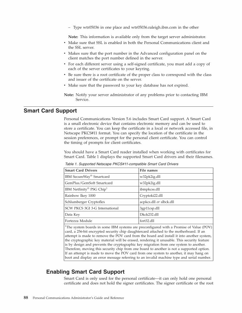
– Type wtr05036 in one place and wtr05036.raleigh.ibm.com in the other
Note: This information is available only from the target server administrator.v Make sure that SSL is enabled in both the Personal Communications client and
the SSL server.v Makes sure that the port number in the Advanced configuration panel on the
client matches the port number defined in the server.v For each different server using a self-signed certificate, you must add a copy of
each of the server certificates to your keyring.v Be sure there is a root certificate of the proper class to correspond with the class
and issuer of the certificate on the server.v Make sure that the password to your key database has not expired.
Note: Notify your server administrator of any problems prior to contacting IBMService.
Smart Card SupportPersonal Communications Version 5.6 includes Smart Card support. A Smart Cardis a small electronic device that contains electronic memory and can be used tostore a certificate. You can keep the certificate in a local or network accessed file, inNetscape PKCS#11 format. You can specify the location of the certificate in thesession preferences, or prompt for the personal client certificate. You can controlthe timing of prompts for client certificates.
You should have a Smart Card reader installed when working with certificates forSmart Card. Table 1 displays the supported Smart Card drivers and their filenames.
Table 1. Supported Netscape PKCS#11-compatible Smart Card Drivers
Smart Card Drivers File names
IBM SecureWay® Smartcard w32pk2ig.dll
GemPlus/GemSoft Smartcard w32pk2ig.dll
IBM Netfinity® PSG Chip1 ibmpkcss.dll
Rainbow Ikey 1000 Cryptoki22.dll
Schlumberger Cryptoflex acpkcs.dll or slbck.dll
SCW PKCS 3GI 3-G International 3gp11csp.dll
Data Key Dkck232.dll
Fortezza Module fort32.dll1The system boards in some IBM systems are preconfigured with a Promise of Value (POV)card, a 256-bit encrypted security chip daughtercard attached to the motherboard. If anattempt is made to remove the POV card from the board and install it into another system,the cryptographic key material will be erased, rendering it unusable. This security featureis by design and prevents the cryptographic key migration from one system to another.Therefore, moving this security chip from one board to another is not a supported option.If an attempt is made to move the POV card from one system to another, it may hang onboot and display an error message referring to an invalid machine type and serial number.
Enabling Smart Card SupportSmart Card is only used for the personal certificate—it can only hold one personalcertificate and does not hold the signer certificates. The signer certificate or the root
88 Personal Communications Administrator’s Guide and Reference

and any intermediate certificate of the personal certificate on the Smart Cardshould be added in the PCommClientKeyDb.kdb file.
To enable Smart Card security using the Certificate Management utility, do thefollowing.1. From the Select Key Database File menu, select Open.2. From the Key database type dropdown, menu, select Crytographic Token
3. Locate the appropriate file or enter the file name and location.
To enable Smart Card support when configuring a session, do the following:1. Select Enable Security in the Host Definition tab panel.2. In the Advanced Security Setup tab panel, select Send Personal Certificate to
Server if Requested.3. Select Cryptographic Support (PKCS#11).4. In the Cryptographic Support Setup panel, choose the Netscape Compatible
PKCS#11 driver name from the drop-down list. If a driver software providerwas not found by Personal Communications, you must enter a Smart Carddriver name.
5. If the driver loaded successfully, the Cryptographic Token Label list isdisplayed. There may be a delay while the certificate labels are loaded.
6. Enter the Cryptographic Token Password for the selected Cryptographic TokenLabel; this provides access to the PKCS#11 Cryptographic device. You can thenaccess the PKCS#11 Certificate Label Names from the drop-down list. If there isonly one Certificate, it will automatically be used.If PKCS#11 Cryptographic support is enabled and a password for the PKCS#11cryptographic module is not defined during configuration, you will beprompted for the password.
Using the IKEYCMD Command-Line InterfaceIKEYCMD is a command-line tool that can be used to manage keys, certificates,and certificate requests. It is functionally similar to Certificate Management(IKEYMAN) and is intended to be run from the command line without a graphicalinterface.
Use IKEYCMD for configuration tasks related to public-private key creation andmanagement. You can use IKEYCMD to create key database files for the same keydatabase types that IKEYMAN currently supports. You can also create certificaterequests, import CA signed certificates, and manage self-signed certificates.
You cannot use IKEYCMD for configuration options that update the serverconfiguration file httpd.conf. To update the server configuration file, you must usethe IBM Administration Server.
Environment Setup for IKEYCMD Command-Line InterfaceUse the following procedure to set the environment variables to use the IKEYCMDcommand-line interface.1. Set or modify the PATH variable to include the location of the Java executables.
This can be done by using the UI, modifying autoexec.bat, or typing thefollowing in a command window:set PATH=c:\Program Files\IBM\Personal Communications\jre\bin;%PATH%;
Chapter 8. Configuring and Using SSL Security for Personal Communications 89

where C:\Program Files\IBM\Personal Communications is the directory whereis Personal Communications installed.
2. Set or modify the PATH variable to include the location of the Java executables.This can be done by using the UI, modifying autoexec.bat, or typing thefollowing in a command window:set CLASSPATH=c:\Program Files\ibm\gsk6\classes\cfwk.zip;C:\ProgramFiles\IBM\gsk6\classes\gsk6cls.jar;%CLASSPATH%;
Once completed, IKEYCMD should run from any directory.
To run an IKEYCMD command, use the following syntax:java com.ibm.gsk.ikeyman.ikeycmd <command>
IKEYCMD Command Line SyntaxThe syntax of the IKEYCMD CLI isjava com.ibm.gsk.ikeyman.ikeycmd <object> <action> [options]
where object is one of the following:
-keydbActions taken on the key database (either a CMS key database file, aWebDB keyring file, or SSLight class)
-cert Actions taken on a certificate
-certreqActions taken on a certificate request
-help Display help for the IKEYCMD invocations
-versionDisplay version information for IKEYCMD
Action is the specific action to be taken on the object, and options are the options(either required or optional) specified for the object and action pair. Some optionsmay be required for certain object and action pairs.
Note: The object and action keywords are position-sensitive and must be in theorder indicated in the example. However, options are not position-sensitiveand can be typed in any order, provided that they are entered as an optionand operand pair.
Object-Action PairsThe following table describes each action that can be performed on a specifiedobject.
Table 2. Object-Action Pairs for IKEYCMD
Object Action Description
-keydb -changepw Change the password for a key database.
-convert Convert the key database from one format to another.
-create Create a key database.
-delete Delete the key database.
-stashpw Stash the password of a key database into a file.
-cert -add Add a CA certificate from a file into a key database.
-create Create a self-signed certificate.
90 Personal Communications Administrator’s Guide and Reference
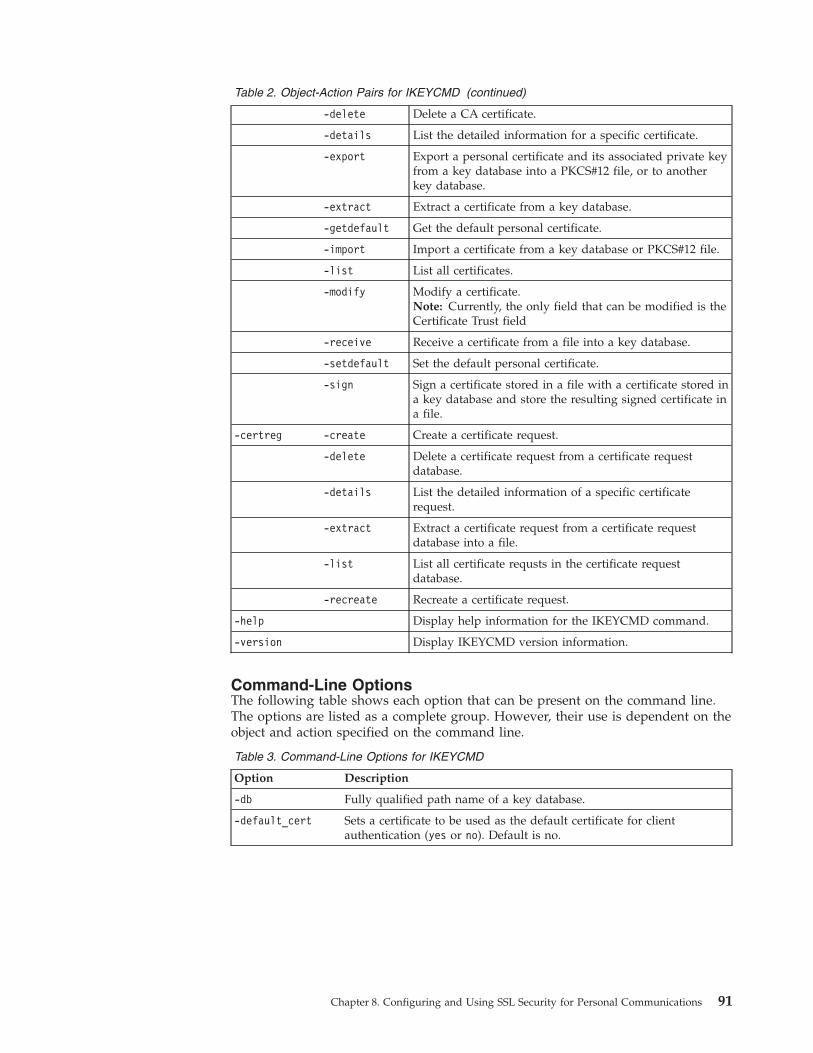
Table 2. Object-Action Pairs for IKEYCMD (continued)
-delete Delete a CA certificate.
-details List the detailed information for a specific certificate.
-export Export a personal certificate and its associated private keyfrom a key database into a PKCS#12 file, or to anotherkey database.
-extract Extract a certificate from a key database.
-getdefault Get the default personal certificate.
-import Import a certificate from a key database or PKCS#12 file.
-list List all certificates.
-modify Modify a certificate.Note: Currently, the only field that can be modified is theCertificate Trust field
-receive Receive a certificate from a file into a key database.
-setdefault Set the default personal certificate.
-sign Sign a certificate stored in a file with a certificate stored ina key database and store the resulting signed certificate ina file.
-certreg -create Create a certificate request.
-delete Delete a certificate request from a certificate requestdatabase.
-details List the detailed information of a specific certificaterequest.
-extract Extract a certificate request from a certificate requestdatabase into a file.
-list List all certificate requsts in the certificate requestdatabase.
-recreate Recreate a certificate request.
-help Display help information for the IKEYCMD command.
-version Display IKEYCMD version information.
Command-Line OptionsThe following table shows each option that can be present on the command line.The options are listed as a complete group. However, their use is dependent on theobject and action specified on the command line.
Table 3. Command-Line Options for IKEYCMD
Option Description
-db Fully qualified path name of a key database.
-default_cert Sets a certificate to be used as the default certificate for clientauthentication (yes or no). Default is no.
Chapter 8. Configuring and Using SSL Security for Personal Communications 91
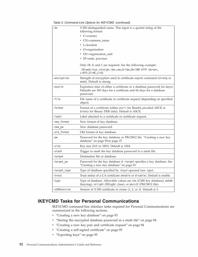
Table 3. Command-Line Options for IKEYCMD (continued)
-dn X.500 distinguished name. This input is a quoted string of thefollowing format:
v C=country
v CN=common_name
v L=location
v O=organization
v OU=organization_unit
v ST=state, province
Only CN, O, and C are required. See the following example:
CN=weblinux.raleigh.ibm.com,O=ibm,OU=IBM HTTP Server,L=RTP,ST=NC,C=US
-encryption Strength of encryption used in certificate export command (strong orweak). Default is strong.
-expire Expiration time of either a certificate or a database password (in days).Defaults are 365 days for a certificate and 60 days for a databasepassword.
-file File name of a certificate or certificate request (depending on specifiedobject).
-format Format of a certificate (either ascii for Base64_encoded ASCII orbinary for Binary DER data). Default is ASCII.
-label Label attached to a certificate or certificate request.
-new_format New format of key database.
-new_pw New database password.
-old_format Old format of key database.
-pw Password for the key database or PKCS#12 file. “Creating a new keydatabase” on page 93on page 27.
-size Key size (512 or 1024). Default is 1024.
-stash Trigger to stash the key database password to a stash file.
-target Destination file or database.
-target_pw Password for the key database if -target specifies a key database. See“Creating a new key database” on page 93.
-target_type Type of database specified by -target operand (see -type).
-trust Trust status of a CA certificate (enable or disable). Default is enable.
-type Type of database. Allowable values are cms (CMS key database), webdb(keyring), sslight (SSLight .class), or pkcs12 (PKCS#12 file).
-x509version Version of X.509 certificate to create (1, 2, or 3). Default is 3.
IKEYCMD Tasks for Personal CommunicationsIKEYCMD command-line interface tasks required for Personal Communications aresummarized in the following sections.v “Creating a new key database” on page 93v “Storing the encrypted database password in a stash file” on page 94v “Creating a new key pair and certificate request” on page 94v “Creating a self-signed certificate” on page 95v “Exporting keys” on page 95
92 Personal Communications Administrator’s Guide and Reference
v “Importing keys” on page 96v “Listing CAs” on page 96v “Storing the CA certificate” on page 96v “Showing the default key in a key database” on page 97
See “Summary of Command-Line Invocations” on page 98 for a summary ofcommand-line invocation syntax examples.
Creating a new key databaseA key database is a file that the Personal Communications client uses to store oneor more key pairs and certificates—this is required to enable secure connectionsbetween the Personal Communications client and the telnet server. Beforeconfiguring SSL communication, you need to have the PCommClientKeyDb.kdbkey database file in the Personal Communications application data directory. Bydefault, this file is installed on your machine with Personal Communications and ithas a default password of pcomm. It is recommended that you change this initialpassword the very first time you use Personal Communications. See “Changing thedatabase password” on page 94 for instructions on how to change the key databasepassword.
To open a key database using the IKEYCMD command-line interface, type thefollowing command:
java com.ibm.gsk.ikeyman.ikeycmd -keydb -open -db
PCommClientKeyDb.kdb -pw <password> -type cms -expire <days> -stash
where:
<password>Password is required for each key database operation. The initial passwordfor PCommClientKeyDb.kdb ispcomm.
-type The PCommClientKeyDb.kdb used by the Personal Communications clientis a CMS database type.
-expireNumber of days before password expires.
-stash Stashes password for key database.
When the -stash option is specified during the key database creation, thepassword is stashed in the PCommClientKeyDb.sth file.
The PCommClientKeyDb.kdb key database file holds all the security informationneeded by the Personal Communications client. Any additions or changes aremade to the existing PCommClientKeyDb.kdb key database file.
Setting the database passwordWhen you create a new key database, specify a key database password. Thispassword protects the private key. The private key is the only key that can signdocuments or decrypt messages encrypted with the public key. Change the keydatabase password frequently.
Use the following guidelines when specifying the password:v The password must be from the U.S. English character set.
Chapter 8. Configuring and Using SSL Security for Personal Communications 93

v The password should be at least six characters and contain at least twononconsecutive numbers. Make sure the password does not consist of publiclyobtainable information about you, such as the initials and birth date for you,your spouse, or children.
v Stash the password.
Note: Keep track of expiration dates for the password. If the password expires, amessage is written to the error log. The server will start, but there will notbe a secure network connection if the password has expired.
Changing the database passwordTo change the database password, type the following command:java com.ibm.gsk.ikeyman.ikeycmd -keydb -changepw -db PCommClientKeyDb.kdb-pw <password> -new_pw<new_password> -expire <days> -stash
where:
-new_pwNew key database password. This password must be different than the oldpassword and cannot be a NULL string.
-expireNumber of days before the password expires.
-stash Stashes password for key database.
Storing the encrypted database password in a stash fileFor a secure network connection, store the encrypted database password in a stashfile.
To store the password while a database is created, type the following command:java com.ibm.gsk.ikeyman.ikeycmd -keydb -create -db <path_to_db>/<db_name>.kdb-pw <password> -type cms -expire <days> -stash
To store the password after a database has been created, type the followingcommand:java com.ibm.gsk.ikeyman.ikeycmd -keydb -stashpw -db <db_name>.kdb -pw <password>
Registering a key database with the serverThe initial configuration setting for the default key database name is key.kdb. If youuse key.kdb as your default key database name, you do not need to register thedatabase with the server. The server uses the initial setting on the KeyFile directivein the configuration file. If you do not use key.kdb as your default key databasename, or, if you create additional key databases, you must register those databases.
Creating a new key pair and certificate requestTo create a public-private key pair and certificate request, do the following:1. Type the following command:
java com.ibm.gsk.ikeyman.ikeycmd -certreq -create -db PCommClientKeyDb.kdb-pw <password> -size <1024 | 512>-dn<distinguished_name>-file <filename> -label <label>
where:
-size Key size of 512 or 1024.
-label Label attached to certificate or certificate request.
-dn Enter an X.500 distinguished name. See Table 3 on page 91 for syntax.
94 Personal Communications Administrator’s Guide and Reference

-file Name of file where the certificate request will be stored. By default,Personal Communications uses the name certreq.arm and it should bestored in the application data directory, where thePCommClientKeyDb.kdb key database is located.
2. Verify that the certificate was successfully created.a. View the contents of the certificate request file you created.b. Make sure the key database recorded the certificate request by typing the
following command:java com.ibm.gsk.ikeyman.ikeycmd -certreq -list -db PCommClientKeyDb.kdb-pw <password>
You should see the label that you just created in the list of certificates. Sendthe newly created file to a certificate authority.
3. Send the newly created file to a certificate authority.
Creating a self-signed certificateIt usually takes two to three weeks to get a certificate from a well-known certificateauthority (CA). While waiting for an issued certificate, use IKEYCMD to create aself-signed server certificate to enable SSL sessions between clients and the server.Use this procedure if you are acting as your own CA for a private Web network.
To create a self-signed certificate, type the following command:java com.ibm.gsk.ikeyman.ikeycmd -cert -create -db PCommClientKeyDb.kdb-pw <password> -size <1024 | 512> -dn <distinguished name>-label <label> -default_cert <yes or no>
where:
-size Key size 512 or 1024.
-label Enter a descriptive comment used to identify the key and certificate in thedatabase.
-dn Enter an X.500 distinguished name. See Table 3 on page 91 for syntax.
-default_certType yes if you want this certificate to be the default certificate in the keydatabase. Otherwise, type no.
Exporting keysTo export keys to another key database or to export keys to a PKCS12 file, type thefollowing command:java com.ibm.gsk.ikeyman.ikeycmd -cert -export -db PCommClientKeyDb.kdb -pw<password> -label <label>-type <cms | sslight> -target <filename>-target_pw <password> -target_type <cms | sslight | pkcs12>-encryption <strong | weak>
where:
-label Label attached to the certificate.
-target Destination file or database.
-target_pwPassword for the target key database.
-target_typeType of the database specified by -target operand.
Chapter 8. Configuring and Using SSL Security for Personal Communications 95

-encryptionStrength of encryption. Default is strong.
Importing keysTo import keys from another key database, type the following command:java com.ibm.gsk.ikeyman.ikeycmd -cert -import -db <filename> -pw <password>-label <label> -type <cms | sslight> -target <filename> -target_pw <password>-target_type <cms | sslight>
To import keys from a PKCS12 file, type the following command:java com.ibm.gsk.ikeyman.ikeycmd -cert -import -file <filename> -pw <password>-type pkcs12 -target <filename> -target_pw <password> -target_type <cms | sslight>
where:
-label Label attached to the certificate.
-target Destination database.
-target_pwPassword for the key database if -target specifies a key database.
-target_typeType of database specified by -target operand.
Listing CAsTo display a list of trusted CAs in the PCommClientKeyDb.kdb key database, typethe following command:java com.ibm.gsk.ikeyman.ikeycmd -cert -list CA -db PCommClientKeyDb.kdb-pw <password>-type cms
Storing the CA certificate
Receiving a CA-signed certificateUse this procedure to receive an electronically mailed certificate from a certificateauthority (CA), designated as a trusted CA on your server. By default, thefollowing CA certificates are stored in the PCommClientKeyDb.kdb key databaseand marked as trusted CA certificates:v IBM World Registry CAv Integrion CA Root (from IBM World Registry)v VeriSign Class 1 Public Primary CAv VeriSign Class 2 Public Primary CAv VeriSign Class 3 Public Primary CAv VeriSign Class 4 Public Primary Cv VeriSign Test CAv RSA Secure Server CA (from VeriSign)v Thawte Personal Basic CAv Thawte Personal Freemail CAv Thawte Personal Premium CAv Thawte Premium Server CAv Thawte Server CA
The CA may send more than one certificate. In addition to the certificate for yourserver, the CA may also send additional Signing certificates or Intermediate CA
96 Personal Communications Administrator’s Guide and Reference

Certificates. For example, Verisign includes an Intermediate CA Certificate whensending a Global Server ID certificate. Before receiving the server certificate, youmust receive any additional Intermediate CA certificates. See “Storing a CAcertificate” for instructions on receiving Intermediate CA Certificates.
Note: If the CA who issues your CA-signed certificate is not a trusted CA in thekey database, you must first store the CA certificate and designate the CA asa trusted CA. Then you can receive your CA-signed certificate into thedatabase. You cannot receive a CA-signed certificate from a CA who is not atrusted CA. For instructions, see “Storing a CA certificate”.
To receive the CA-signed certificate into a key database, type the followingcommand:java com.ibm.gsk.ikeyman.ikeycmd -cert -receive -file <filename>-db PCommClientKeyDb.kdb -pw <password> -format<ascii | binary> -default_ cert <yes | no>
where:
-formatCertificate Authority might provide CA Certificate in either ASCII orbinary format.
-label Label attached to CA certificate.
-trust Indicates whether this CA can be trusted. Use enable options whenreceiving a CA certificate.
-file File containing the CA certificate.
-default_ certType yes if you want to make this key your default key
Storing a CA certificateTo store a certificate from a CA who is not a trusted CA, type the followingcommand:java com.ibm.gsk.ikeyman.ikeycmd -cert -add -db PCommClientKeyDb.kdb-pw <password>-label <label> -format <ascii> -trust <enable> -file <file>
where:
-label Label attached to certificate or certificate request.
-formatCertificate Authorities might supply a binary ASCII file.
-trust Indicate whether this CA can be trusted (should be yes).
Opening a key databaseExplicit opening of a key database is not supported. For each command, databaseand password options are given—these options are sufficient to operate in a keydatabase.
Showing the default key in a key databaseTo display the default key entry, type the following command:java com.ibm.gsk.ikeyman.ikeycmd -cert -getdefault -db PCommClientKeyDb.kdb-pw <password>
Chapter 8. Configuring and Using SSL Security for Personal Communications 97
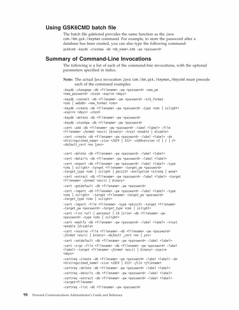
Using GSK6CMD batch fileThe batch file gsk6cmd provides the same function as the javacom.ibm.gsk.ikeyman command. For example, to store the password after adatabase has been created, you can also type the following command:gsk6cmd -keydb -stashpw -db <db_name>.kdb -pw <password>
Summary of Command-Line InvocationsThe following is a list of each of the command-line invocations, with the optionalparameters specified in italics.
Note: The actual Java invocation java com.ibm.gsk.ikeyman,iKeycmd must precedeeach of the command examples.
-keydb -changepw -db <filename> -pw <password> -new_pw<new_password> -stash -expire <days>
-keydb -convert -db <filename> -pw <password> -old_format<cms | webdb> -new_format <cms>
-keydb -create -db <filename> -pw <password> -type <cms | sslight>-expire <days> -stash
-keydb -delete -db <filename> -pw <password>
-keydb -stashpw -db <filename> -pw <password>
-cert -add -db <filename> -pw <password> -label <label> -file<filename> -format <ascii |binary> -trust <enable | disable>
-cert -create -db <filename> -pw <password> -label <label> -dn<distinguished_name> -size <1024 | 512> -x509version <3 | 1 | 2>-default_cert <no |yes>
-cert -delete -db <filename> -pw <password> -label <label>
-cert -details -db <filename> -pw <password> -label <label>
-cert -export -db <filename> -pw <password> -label <label> -type<cms | sslight> -target <filename> -target_pw <password>-target_type <cms | sslight | pkcs12> -encryption <strong | weak>
-cert -extract -db <filename> -pw <password> -label <label> -target<filename> -format <ascii | binary>
-cert -getdefault -db <filename> -pw <password>
-cert -import -db <filename> -pw <password> -label <label> -type<cms | sslight> -target <filename> -target_pw <password>-target_type <cms | sslight>
-cert -import -file <filename> -type <pkcs12> -target <filename>-target_pw <password> -target_type <cms | sslight>
-cert -list <all | personal | CA |site> -db <filename> -pw<password> -type <cms | sslight>
-cert -modify -db <filename> -pw <password> -label <label> -trust<enable |disable>
-cert -receive -file <filename> -db <filename> -pw <password>-format <ascii | binary> -default _cert <no | yes>
-cert -setdefault -db <filename> -pw <password> -label <label>
-cert -sign -file <filename> -db <filename> -pw <password> -label<label> -target <filename> -format <ascii | binary> -expire<days>
-certreq -create -db <filename> -pw <password> -label <label> -dn<distinguished_name> -size <1024 | 512> -file <filename>
-certreq -delete -db <filename> -pw <password> -label <label>
-certreq -details -db <filename> -pw <password> -label <label>
-certreq -extract -db <filename> -pw <password> -label <label>-target<filename>
-certreq -list -db <filename> -pw <password>
98 Personal Communications Administrator’s Guide and Reference

-certreq -recreate -db <filename> -pw <password> -label <label>-target<filename>
-help
-version
Chapter 8. Configuring and Using SSL Security for Personal Communications 99

100 Personal Communications Administrator’s Guide and Reference

Chapter 9. ODBC Drivers and Database Access Utility
This chapter contains information about ODBC drivers and the Database Accessutility. Should you require more detailed information, refer to the following guides:v IBM DB2 Connect Personal Edition Quick Beginnings — S10J-8162–00v IBM DB2 Connect User’s Guide — S10J-8163–00
You can also find additional information in the online help.
Overview of Open Database Connectivity (ODBC)ODBC is an industry standard application program interface (API) that provides asolution to a common problem—how to write programs that access a DatabaseManagement System (DBMS) without making them dependent on specific DBMSdesigns. ODBC provides API access to SQL-accessible databases, allowingapplication programs to use SQL to access data from many kinds of sources. Theindependence of the access method from the original design of the database meansthat developers can design and produce a single version of an application that canwork with, for example, DB2 Connect™, Oracle, or Sybase data, without requiringa separate version for each DBMS. Users simply add database drivers to link theapplication to their choice of DBMS.
ODBC is a component of the Windows Open Services Architecture (WOSA).Personal Communications Version 5.6 supports ODBC 2.0, for development of32-bit applications for Windows 95, Windows 98, Windows NT, Windows Me,Windows 2000, and Windows XP.
An ODBC driver provides an application program with standard and uniform SQLaccess to a DBMS database. An ODBC driver allows the designers and users of theapplication program to ignore the SQL differences between various DBMS systems.
Figure 1 shows an overview of the Personal Communications Database Accessutility and the ODBC DB2® drivers.
V3R1 ODBC Server DB2/400Data Base
DB2/MVSData Base
Copy/Paste PC Data Base
MVSAS/400Host Systems
PC SideAdvanced Program to Program Communication
ODBC Administrator (provided by Microsoft)
Data Base Access Utility (PCSDB.EXE)
Microsoft Excel Lotus 1-2-3Windows
ApplicationProgram
OEM ODBC Driver
Figure 1. Database Access Overview
© Copyright IBM Corp. 1989, 2002 101

Components of ODBCThere are four components in the ODBC architecture:v The application component defines and performs the work to be accomplished.
It calls the ODBC API functions that submit SQL statements and retrieve results.v The driver manager component loads drivers on behalf of an application.v The driver component processes ODBC function calls, submits SQL requests to a
specific data source, and passes results to the application. The driver transformsthe application’s SQL syntax into the syntax expected by the driver’s associatedDBMS.
v The data source component is the data to be accessed and the means for doingso, including the associated operating system, DBMS and network platform.
From the application program’s perspective, the driver manager and the driverappear to be a single unit for processing ODBC function calls. Figure 2 shows therelationship between the four components:
Application ComponentAn application using ODBC performs the following tasks:v Requests a session (connection) with a data source.v Sends SQL requests to the data source.v Defines storage areas and data formats for the results of the SQL requests.v Requests the results of the defined query.v Processes errors.v Requests commit or rollback operations for transaction control.v Terminates the session with the data source.
Any program that accesses a DBMS, such as a spreadsheet, a mail server, or areport generator, can be designed to use ODBC.
Application
Driver Manager
AS/400ODBCDriver
MVSODBCDriver
OtherODBCDriver
DataSource
DataSource
DataSource
DB2/400 DB2/MVS other
ODBC Interface
Figure 2. ODBC Components
102 Personal Communications Administrator’s Guide and Reference

Driver ManagerThe driver manager is a dynamic link library (DLL), the purpose of which is toload drivers. It also performs the following functions:v Maps a data source name to a specific driver DLL.v Processes ODBC initialization calls.v Provides the entry points to the ODBC functions for each driver.v Provides parameter and sequence validation for ODBC calls.
DriverA driver is a DLL that implements ODBC function calls and interacts with a datasource.
The driver manager loads a driver when the application calls theSQLBrowseConnect, SQLConnect, or SQLDriverConnect function.
A driver performs the following tasks in response to ODBC function calls from anapplication:v Establishes a connection to a data source.v Submits requests to the data source.v Translates data to or from other formats, if requested by the application.v Returns results to the application.v Formats errors into standard error codes and returns them to the application.v Declares and manipulates cursors if necessary. This operation is invisible to the
application unless there is a request for access to a cursor name.v Initiates transactions of the data source. This operation is invisible to the
application.
Data SourceA data source is an instance of a DBMS product and any remote operating systemand the protocol required to access it.
Database Access UtilityDatabase Access lets you access host or PC databases and retrieve data, usingODBC drivers. If you specify the conditions for accessing data in each window, thedesired query can be created automatically. See the online help for extensiveinformation on using the Database Access utility with the PersonalCommunications ODBC drivers.
From Database Access, you can perform any of the following actions:v You can see and modify the SQL statements that are created automatically.v You can see available database table lists.v You can copy spreadsheet data to the clipboardv You can show data in the grid in the main window spreadsheet, send data to
other applications (for example Lotus® 1-2-3® or Microsoft Excel), or send datato a printer.
v If you want to know the meaning of items in the windows, you can see anexplanation when you click on the item and then click help.
Accessing an ODBC Data SourceTo access an ODBC data source, do one of the following:
Chapter 9. ODBC Drivers and Database Access Utility 103
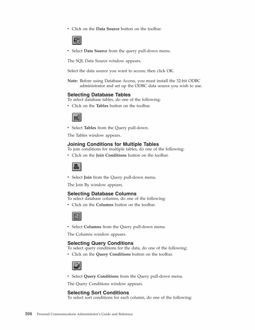
v Click on the Data Source button on the toolbar.
v Select Data Source from the query pull-down menu.
The SQL Data Source window appears.
Select the data source you want to access; then click OK.
Note: Before using Database Access, you must install the 32-bit ODBCadministrator and set up the ODBC data source you wish to use.
Selecting Database TablesTo select database tables, do one of the following:v Click on the Tables button on the toolbar.
v Select Tables from the Query pull-down.
The Tables window appears.
Joining Conditions for Multiple TablesTo join conditions for multiple tables, do one of the following:v Click on the Join Conditions button on the toolbar.
v Select Join from the Query pull-down menu.
The Join By window appears.
Selecting Database ColumnsTo select database columns, do one of the following:v Click on the Columns button on the toolbar.
v Select Columns from the Query pull-down menu.
The Columns window appears.
Selecting Query ConditionsTo select query conditions for the data, do one of the following:v Click on the Query Conditions button on the toolbar.
v Select Query Conditions from the Query pull-down menu.
The Query Conditions window appears.
Selecting Sort ConditionsTo select sort conditions for each column, do one of the following:
104 Personal Communications Administrator’s Guide and Reference

v Click on the Order button on the toolbar.
v Select Order from the Query pull-down menu.
The Order By window appears.
Viewing the Current SQL StatementTo view the current SQL statement, do one of the following:v Click on the SQL Statement button on the toolbar.
v Select SQL Statement from the Query pull-down menu.v Click the SQL button in any window selected from the Query pull-down menu.
The SQL Statement window appears.
Database Size LimitWhen you use Database Access, the maximum number of each value that can bedisplayed in the spreadsheet is as follows:
Number of columns 400Number of rows 16350Column length 2048 bytesRow length 2048 bytesSQL statement’s length 32766 bytes
Note: The values shown are standard, but your PC’s available resources (such asmemory) can result in other limits.
When you use another application (for example Lotus 1-2-3), refer to the manualfor that application because the limit might be different.
Chapter 9. ODBC Drivers and Database Access Utility 105

106 Personal Communications Administrator’s Guide and Reference

Chapter 10. Express Logon Feature
The Express Logon Feature allows a Personal Communications Telnet 3270 user tosecurely logon to a host application without sending the User ID and password.One advantage of using this function is that it reduces the time you spendmaintaining host user IDs and passwords. It also reduces the number of user IDsand passwords that the users have to remember.
To use Express Logon, the host session must be configured for SSL and clientauthentication. This means the client must have a valid client certificate. The SSLconnection must be made to one of the supported Telnet 3270 servers.
Using Express LogonWhen starting a session using Express Logon, Personal Communicationsestablishes an SSL client authentication session with the Telnet 3270 server. Duringthe logon process, a macro with the Express Logon information is played. Once thesession is established, Personal Communications sends the application ID for theapplication that the user is accessing to the Telnet 3270 server. This information iscontained in the logon macro. The Telnet 3270 server uses certificate informationfrom the SSL connection and the application ID received from PersonalCommunications, and requests the user ID and passticket (a temporary password)from the host access control program (such as RACF®).
Personal Communications uses the macro function to put predefined substitutestrings in the user ID and password fields. The Telnet 3270 server substitutes theuser ID and passticket in the appropriate place in the 3270 datastream. The logonis completed.
After an ELF macro is recorded, it can be distributed to multiple users for playbackwithout further modification.
Preparing to Configure the Express Logon FeatureBefore you configure an Express Logon macro, you need to have the followinginformation.v Host application name
Name of the host application the user is logging onto. For example, the nameentered on the USSMSG10 screen.
v Host access application IDThis name must match the RACF PTKTDATA (Passticket Data Profile)application name that is configured on the OS/390® (V2R10 or later) or z/OShost. This name could be the same as the application name that the user islogging onto (for example, the name on USSMSG10). When creating PTKTDATAprofiles for applications such as TSO, the application name portion of the profilewill most likely not be the same. For example, RACF requires that theapplication ID portion of the profile name be TSO+SID. Refer to the OS/390V2R10.0 SecureWay Security Server RACF Security Administrator’s Guide or thez/OS V1R1.0 SecureWay Security Server RACF Security Administrator’s Guide todetermine the correct profile naming.
v User ID and password for the application that you are logging on to.
© Copyright IBM Corp. 1989, 2002 107

During macro recording, the actual user ID and password are used. They are notrecorded in the macro; only the predefined substitute strings are recorded in themacro. The Telnet 3270 server replaces the predefined substitute strings with theactual user ID and password during the logon process.
v Client Security CertificateThe security certificate for the client must be stored in RACF using the RACFRACDCERT command.– For information about using digital certificates with RACF, refer to the
following books:- For OS/390, refer to OS/390 V2R10.0 SecureWay Security Server RACF
Security Administrator’s Guide and OS/390 V2R10.0 SecureWay Security ServerRACF Command Language Reference.
- For z/OS, refer to z/OS V1R1.0 SecureWay Security Server RACF SecurityAdministrator’s Guide and z/OS V1R1.0 SecureWay Security Server RACFCommand Language Reference.
– For information about configuring DCAS to use RACF certificates, refer to thefollowing books:- For OS/390, refer to OS/390 V2R10.0 IBM Communication Server IP
Migration.- For z/OS, refer to z/OS V1R1.0 IBM Communication Server IP Migration.
Configuring Express Logon
Recording the MacroYou must record a macro for each host application that you want to access. Youcannot log on to multiple applications with one macro. You do not have toconfigure SSL, and client authentication is not required on the telnet servers andOS/390 or z/OS before recording the logon macro, but you must do this beforeyou can play the macro.
Manual Configuration of an ELF MacroYou can manually configure an existing Macro format file for ELF use. Theprocedure is as follows:1. From the Action Bar, open the macro file containing the recorded keystrokes by
selecting Edit → Preferences → Macro/Script.2. Select the macro file you just recorded and then select Customize.3. Replace the UserID recorded in the macro with two tags: the ELF Application
ID and the ELF UserID placeholder. The Application ID tag consists of threewords, each separated by a blank character: elf, applid, and the identifier ofthe host application that will be logged onto. The UserID placeholder is)USR.ID(.For example, replace "myUserID with ")USR.ID(.
4. Replace the Password recorded in the macro with the ELF Passwordplaceholder tag )PSS.WD(.For example, replace "myPassword with ")PSS.WD(.
Limitations of the Logon Macrov Automatic insertion of the user ID and password placeholders into the recorded
macro requires that the password be typed into the first non-display input field.The user ID is assumed to have been entered just prior to the password. The
108 Personal Communications Administrator’s Guide and Reference

Modified Data Tag attribute of each formatted input field is assumed to be ONonly when the field has been modified by the operator.
v There is a short delay while the Telnet 3270 server acquires the passticket fromthe host access control facility. The amount of time is probably less than theusual delay incurred when the user enters a user ID and password. However,the user can see the macro proceed through the screens during the logonprocess.
v Logon Express recording requires that the host program uses 3270 fieldattributes to define the password field on the screen.
Problem DeterminationIf the client logon fails and displays the messages )USR.ID( NOT IN CP DIRECTORY,INVALID USERID, )USR.ID(, PASSWORD NOT AUTHORIZED or any similar messages,check the Telnet 3270 server log for details.
Possible reasons for failures are:v The application ID defined in the macro is not valid.v The Telnet 3270 server could not connect to DCAS. The host might be down.v The client certificate is not defined in RACF or it is not valid.v The passticket has expired and could not be used to log on.v The Telnet 3270 server completed scanning of data stream without replacing the
user ID or password.v The Telnet 3270 server or the host does not support the Express Logon Feature.
Chapter 10. Express Logon Feature 109

110 Personal Communications Administrator’s Guide and Reference

Part 3. SNA and AnyNet Topics
© Copyright IBM Corp. 1989, 2002 111

112 Personal Communications Administrator’s Guide and Reference
Chapter 11. SNA Client/Server Concepts
TerminologyAdvanced Program-to-Program Communication (APPC)
An implementation of the SNA LU 6.2 protocol that allows interconnectedsystems to communicate and share the processing of programs.
Advanced Peer-to-Peer Networking (APPN)An enhancement for Systems Network Architecture (SNA) networksfeaturing:v Dynamic exchange of network topology information that simplifies
connections, route selection, network definition, and reconfigurationv Automated resource registration and directory lookupv Greater distributed network control that helps to isolate the effects of
single points of failure
Common Programming Interface for Communications (CPI-C)Personal Communications provides support for the Common ProgrammingInterface for Communications (CPI-C) 2.0 industry standard interface fromX/Open. The CPI-C interface enables greater application portability acrossdifferent platforms. By using CPI-C 2.0, APPC programming is simplified,resulting in reduced cycle time, and enhanced client/server computingcapability. This support provides the capability for distributed parts of anapplication to converse with one another. The implementation is consistentwith the Conversational function described in the IBM Open Blueprint®.
Logical Unit Address (LUA)System software and interfaces that supply input/output (I/O) serviceroutines to support communications that use LU types 0, 1, 2, and 3 SNAprotocols. These protocols support user defined data streams, SNAcharacter streams, and SNA 3270 data streams. LUA services include onlythose services that support data communications. LUA does not supplyany device emulation facilities.
Node An endpoint of a link, or a junction, common to two or more links in anetwork. Nodes can be linked to host processors, communicationcontrollers, cluster controllers, terminals, or workstations.
End NodeProvides directory and routing services for a workstation on an APPNnetwork.
If the workstation will not be connecting from an end node to a networknode server, you need to define an SNA connection.
APPC ConceptsPersonal Communications provides Advanced Peer-to-Peer Networking (APPN)end node support for workstations, allowing them to communicate more flexiblywith other systems in the network.
Personal Communications provides advanced program-to-programcommunications (APPC) to support communications between distributed
© Copyright IBM Corp. 1989, 2002 113

processing programs, called transaction programs (TPs). APPN extends thiscapability to a networking environment. The TPs can be located at any node in thenetwork that provides APPC.
Introducing APPC and CPI-CAdvanced Program-to-Program Communication (APPC), also known as LU 6.2, issoftware that enables high-speed communications between programs on differentcomputers, from portables and workstations to midrange and host computers.APPC software is available for many different IBM and non-IBM operatingsystems, either as part of the operating system or as a separate software package.
APPC serves as an interface between application programs and the network. Whenthe communications application on your workstation passes information to theAPPC software, APPC takes the information and sends it on to a networkinterface, such as a token ring adapter card. The information travels across thenetwork to another computer, where the APPC software receives the informationfrom the network interface. APPC puts the information back into its originalformat and passes it to the corresponding communications application.
APPC provides a consistent set of functions for program-to-programcommunications across different platforms. But, the architecture did not specify acommon application programming interface (API) for implementing thesefunctions. As a result, each operating system that supports APPC developed itsown API, a set of verbs that closely resemble the operating system itself. Thesedifferences do not pose a problem if you are writing programs for two computersthat use the same operating system. Most client/server applications run ondifferent types of computers, however, to take advantage of the strengths of eachcomputer. So, if you are designing programs for different operating systems, youmust learn how to use two or more different sets of verbs.
The Common Programming Interface for Communications (CPI-C) eliminates thisproblem. CPI-C provides one standard set of verbs, known as CPI-C calls, for allsystems that support CPI-C. As a result, you learn only one set of calls to writeclient/server applications for different systems.
What Is a Transaction Program?The part of the communications application that initiates or responds to APPCcommunications is called a transaction program. A transaction program is not anentire, stand-alone program. Instead, it is the part of the program that handlestransactions (exchanges of data) with another program.
When people talk with each other, we say that they are having a conversation.Likewise, the communication between two transaction programs is called aconversation.
A conversation between two programs is similar to a conversation between twopeople. When you have a conversation with another person, you follow unwrittenrules that govern how you begin and end the conversation, take turns speaking,and exchange information. Similarly, APPC is called a protocol because it providesthe rules that govern how conversations between transaction programs start andstop, which program “speaks” first, and how data is exchanged. Computers needcomplete and rigid rules for conversations between programs. For that reason,APPC consists of a set of well-defined and thorough rules to cover all possiblecommunications situations.
114 Personal Communications Administrator’s Guide and Reference
An APPC program may have several conversations active at one time, with thesame transaction program or with different transaction programs.
Every transaction program needs a partner to communicate with. Thus, transactionprograms are developed in pairs called partner transaction programs.
People use different parts of speech to communicate with each other. Transactionprograms are more limited in their communications; they use only verbs tocommunicate with each other. The verbs are the programming language you use tostart, stop, and control conversations.
A transaction program consists of APPC and CPI-C verbs such as:
ALLOCATE (CMALLC in CPI-C)Starts a conversation with another transaction program
SEND_DATA (CMSEND in CPI-C)Sends data to the partner transaction program
RECEIVE (CMRCV in CPI-C)Receives data from the partner transaction program
DEALLOCATE (CMDEAL in CPI-C)Ends a conversation with another transaction program.
The APPC verbs make up the application programming interface (API) for APPCand CPI-C. In other words, these verbs represent the interface between thetransaction program and the APPC software.
What Is the Difference between APPC and APPN?APPC is a communications protocol that enables programs on different computersto “talk to” each other. APPC provides the interface between the programs and thenetworking hardware and software and defines the rules that programs use toexchange information.
Advanced Peer-to-Peer Networking (APPN) is the underlying networking protocolthat routes APPC traffic through intermediate nodes in the network. For instance,when Program A uses APPC to talk to Program B, APPN finds the node whereProgram B is located and directs the APPC traffic through the network.
APPN includes several features that help reduce the amount of configurationrequired to set up and maintain a network. These features automate many tasksthat are time-consuming, complicated, and error-prone. For example, if you’reinstalling a new workstation that uses APPN, you don’t have to set upconfiguration information for every workstation you want to communicate with.You simply provide the name of the computer and the address of the intermediatenode that handles your traffic. APPN takes care of the rest of the informationneeded to route APPC traffic to and from your workstation.
If you connect to an APPN network, you simplify your own configuration andmake it easier for other computers in the network to find you.
Side Information DefinitionsBefore starting a conversation with a partner program, a CPI-C program requiresthe following information:v The name of the partner programv The name of the LU on the remote computer
Chapter 11. SNA Client/Server Concepts 115

v The type of session used by the programv Security information
If the CPI-C partner program uses a blank symbolic destination name, a sideinformation definition is not necessary.
Improving Productivity Using APPCThe advanced features of APPC help speed the development of robustclient/server applications and keep development costs low.
Client/server applications often prove to be especially challenging to theprogrammer. It’s not enough to understand the details about the computer andoperating system that your application uses. If you’re designing client/serverapplications, you have to deal with computers used by both sides of theapplication, as well as the intervening network. For instance, implementingeffective security measures is more important and more complicated, since youmust ensure security throughout the network. In addition, synchronization anderror reporting are often problematic in a distributed environment, because bothsides of the application must coordinate their work.
One reason that APPC has become so widely used in client/server applications isthat it furnishes a complete set of useful functions like security, synchronization,and error reporting. If you use other protocols, you must build these functions inevery application you write. For example, if you use NetBIOS, you must designand implement a strategy for security for each application. Not only does thisapproach require additional work, it may result in a number of incompatiblesecurity systems in your network. By contrast, APPC includes a common set ofsecurity services that are consistent across all APPC platforms.
Similarly, most protocols do not include synchronization functions. Synchronizationis required by any program that cannot continue processing data until the datasent to the partner program has been received and processed. Rather than writingyour own synchronization routine, APPC provides a Confirm call that you can useto handle synchronization between two programs.
Improving Productivity Using CPI-CBecause many client/server applications are distributed between mainframesystems and workstations, host programmers and workstation programmers mustwork together to develop partner applications. CPI-C bridges the gap betweenthese programmers by providing a common language for designing thecommunications part of the applications. CPI-C also enables you to write thecommunications portion of an application without knowing the details of theoperating system. After you write a CPI-C application, you can easily move theprograms from one operating system to another with few changes. So, by using theCPI-C interface, you can port both your applications and your programming skillsfrom one system to another, quickly and cost-effectively.
What Is a Logical Unit?Every TP gains access to an SNA network through a logical unit (LU). An LU isSNA software that accepts verbs from your programs and acts on those verbs. ATP issues APPC verbs to its LU. These verbs cause commands and data to flowacross the network to a partner LU. An LU also acts as an intermediary between
116 Personal Communications Administrator’s Guide and Reference

the TPs and the network to manage the exchange of data between TPs. A singleLU can provide services for multiple TPs. Multiple LUs can be active in the nodesimultaneously.
LU TypesPersonal Communications supports LU types 0, 1, 2, 3, and 6.2. LU types 0, 1, 2,and 3 support communication between host application programs and differentkinds of devices, such as terminals and printers.
LU 6.2 supports communications between two programs located at type 5 subareanodes, type 2.1 peripheral nodes, or both, and between programs and devices.APPC is an implementation of the LU 6.2 architecture.
Communication occurs only between LUs of the same LU type. For example, anLU 2 communicates with another LU 2; it does not communicate with an LU 3.
When Personal Communications is configured, your local and partner LUs aredefined once for each machine. When you design programs, you must understandthe capabilities supported by the LU in the particular machines you plan to use.
Dependent and Independent LUsA dependent LU depends on a system services control point (SSCP) to activate asession. A dependent LU needs an active SSCP-LU session, which the dependentLU uses to start an LU-LU session with an LU in a subarea node. A dependent LUcan have only one session at a time with the subarea LU. For communications witha TP at a subarea node, each dependent LU can have only one conversation at atime, and each dependent LU can support communications for only one TP at atime.
An independent LU does not depend on an SSCP to activate a session. Anindependent LU supports multiple concurrent sessions with other LUs in a subareanode, so you can have multiple conversations and support multiple TPs forcommunications with subarea TPs. LUs between peripheral nodes also use thissupport.
The distinction between a dependent LU and an independent LU is meaningfulonly when discussing a session between an LU in a peripheral node and an LU ina subarea node. Otherwise, dependent and independent LUs both support multipleconcurrent sessions and conversations when communicating between type 2.1peripheral nodes, for example, between two Windows NT workstations. A PersonalCommunications LU can support a single session with a dependent LU or multiplesessions with an independent LU.
What Is a Session?Before TPs can communicate with each other their LUs must be connected in amutual relationship called a session. A session connects two LUs, so it is called anLU-LU session. Figure 3 on page 118 illustrates this communication relationship.Multiple, concurrent sessions between the same two LUs are called parallel LU-LUsessions.
Chapter 11. SNA Client/Server Concepts 117

Sessions act as conduits that manage the movement of data between a pair of LUsin an SNA network. Specifically, sessions deal with things such as the quantity ofdata transmitted, data security, network routing, and traffic congestion.
Sessions are maintained by their LUs. Normally, your TPs do not deal with sessioncharacteristics. You define session characteristics when you:v Configure your systemv Use the Session Services function in the Subsystem Management windowsv Use the management verbs
What Is a Conversation?The communication between TPs is called a conversation. Conversations occuracross LU-LU sessions. A conversation starts when a TP issues an APPC verb orCPI-C call that allocates a conversation. The conversation style associated with theconversation indicates the style of data transfer to be used, two-way alternate ortwo-way simultaneous. A conversation that specifies a two-way alternate style ofdata transfer is also known as a half-duplex conversation. A conversation thatspecifies a two-way simultaneous style of data transfer is referred to as a full-duplexconversation.
When a half-duplex conversation is allocated to a session, a send-receiverelationship is established between the TPs connected to the conversation, and atwo-way alternate data transfer occurs where information is transferred in bothdirections, one direction at a time. Like a telephone conversation, one TP calls theother, and they “converse”, one TP talking at a time, until a TP ends theconversation. One TP issues verbs to send data, and the other TP issues verbs toreceive data. When it finishes sending data, the sending TP can transfer sendcontrol of the conversation to the receiving TP. One TP decides when to end theconversation and informs the other when it has ended.
When a full-duplex conversation is allocated to a session, both TPs connected tothe conversation are started in send-and-receive state, and a two-way simultaneousdata transfer occurs where information is transferred in both directions at the sametime. Both TPs may issue verbs to send and receive data simultaneously with notransfer of send control required. The conversation ends when both TPs indicatethey are ready to stop sending data, and each TP has received the data sent by thepartner. If an error condition occurs, one TP may decide to end both sides of theconversation abruptly.
Conversations can exchange control information and data. The TP should select theconversation style best suited for its application.
Figure 3. A Session between Two LUs
118 Personal Communications Administrator’s Guide and Reference

A Conversation between Two TPsFigure 4 shows a conversation between two TPs as it occurs over a session.
A session can support only one conversation at a time, but one session can supportmany conversations in sequence. Because multiple conversations can reusesessions, a session is a long-lived connection compared to a conversation. When aprogram allocates a conversation and all applicable sessions are in use, the LU putsthe incoming Attach (allocation request) on a queue. It completes the allocationwhen a session becomes available.
Two LUs can also establish parallel sessions with each other to support multipleconcurrent conversations. A parallel session occurs when either TP allocates aconversation, and a session exists but is being used by a conversation. The LU canrequest a new session to satisfy the allocation.
Parallel Sessions between LUsFigure 5 shows three parallel sessions between two LUs; each session carries aconversation.
SNA CommunicationsPersonal Communications supports Systems Network Architecture (SNA) type 2.1nodes (including SNA type 2.0 and SNA type 2.1 support for LUs other than SNALU 6.2). This support lets you write programs to communicate with many otherIBM SNA products.
You can write programs without knowing the details of the underlying network.All you need to know is the name of the partner LU; you do not need to know itslocation. SNA determines the partner LU location and the best path for routingdata. A change to the underlying network, such as a physical address change, the
Figure 4. A Conversation between Two TPs
Figure 5. Parallel Sessions between LUs
Chapter 11. SNA Client/Server Concepts 119

addition of a new adapter, or the relocation of a machine, does not affect APPCprograms. A program might, however, need to establish link connections overswitched SDLC connections.
When Personal Communications starts, it establishes local LU and logical linkdefinitions, which are stored in a configuration file. The system managementapplication programming interface (API) provides functions that controlconfiguration definition and adapter and link activation.
SNA Node OperationsWith SNA Node Operations, either a user or system administrator can displayinformation or take action on node resources that are known to the active node.
The following tasks are supported:v Starting and stopping resourcesv Deleting resourcesv Displaying resource informationv Changing session limitsv Initiating path switches
Refer to the information about SNA node operations in the 3270 Emulator User’sReference, 5250 Emulator User’s Reference, or the online help for information on usingSNA node operations.
120 Personal Communications Administrator’s Guide and Reference
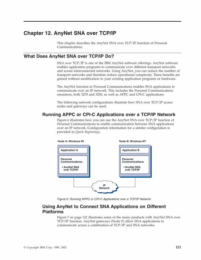
Chapter 12. AnyNet SNA over TCP/IP
This chapter describes the AnyNet SNA over TCP/IP function of PersonalCommunications.
What Does AnyNet SNA over TCP/IP Do?SNA over TCP/IP is one of the IBM AnyNet software offerings. AnyNet softwareenables application programs to communicate over different transport networksand across interconnected networks. Using AnyNet, you can reduce the number oftransport networks and therefore reduce operational complexity. These benefits aregained without modification to your existing application programs or hardware.
The AnyNet function in Personal Communications enables SNA applications tocommunicate over an IP network. This includes the Personal Communicationsemulators, both 3270 and 5250, as well as APPC and CPI-C applications.
The following network configurations illustrate how SNA over TCP/IP accessnodes and gateways can be used.
Running APPC or CPI-C Applications over a TCP/IP NetworkFigure 6 illustrates how you can use the AnyNet SNA over TCP/IP function ofPersonal Communications to enable communication between SNA applicationsover an IP network. Configuration information for a similar configuration isprovided in Quick Beginnings.
Using AnyNet to Connect SNA Applications on DifferentPlatforms
Figure 7 on page 122 illustrates some of the many products with AnyNet SNA overTCP/IP function. AnyNet gateways (Node F) allow SNA applications tocommunicate across a combination of TCP/IP and SNA networks.
IPNetwork
Node A: Windows 95 Node B: Windows NT
Application A
PersonalCommunications
• AnyNet SNAover TCP/IP
Application B
PersonalCommunications
• AnyNet SNAover TCP/IP
Figure 6. Running APPC or CPI-C Applications over a TCP/IP Network
© Copyright IBM Corp. 1989, 2002 121

Chaining Gateways to Connect Multiple SNA and IP NetworksChained gateways enable the SNA network to connect multiple IP networks.
Note: While Figure 8 on page 123 shows three networks connected, the number ofnetworks that can be concatenated is unlimited.
IP
Node A: Windows 95 Node B: OS/2
Application A
PersonalCommunications
• AnyNet SNAover TCP/IP
Application B
PersonalCommunications
• AnyNet SNAover TCP/IP
Node C: OS/400 Node D: AIX
Application C
OS/400
• SNA• AnyNet SNA
over TCP/IP• TCP/IP
Application D
CommunicationsServer for AIX
• AnyNet APPCover TCP/IP
CommunicationsServer
• AnyNet SNAover TCP/IPGateway
Node F:OS/2,MVSor AIX
SNA
LU6.2
Node E:
Figure 7. Using AnyNet to Connect SNA Applications on Different Platforms
122 Personal Communications Administrator’s Guide and Reference
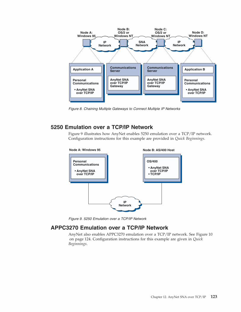
5250 Emulation over a TCP/IP NetworkFigure 9 illustrates how AnyNet enables 5250 emulation over a TCP/IP network.Configuration instructions for this example are provided in Quick Beginnings.
APPC3270 Emulation over a TCP/IP NetworkAnyNet also enables APPC3270 emulation over a TCP/IP network. See Figure 10on page 124. Configuration instructions for this example are given in QuickBeginnings.
IPNetwork
Node D:Windows NT
SNANetwork
IPNetwork
Node A:Windows 95
Application A
PersonalCommunications
• AnyNet SNAover TCP/IP
CommunicationsServer
AnyNet SNAover TCP/IPGateway
Node B:OS/2 or
Windows NT
CommunicationsServer
AnyNet SNAover TCP/IPGateway
Application B
PersonalCommunications
• AnyNet SNAover TCP/IP
IPNetwork
Node C:OS/2 or
Windows NT
Figure 8. Chaining Multiple Gateways to Connect Multiple IP Networks
IPNetwork
PersonalCommunications
• AnyNet SNAover TCP/IP
Node A: Windows 95
OS/400
• AnyNet SNAover TCP/IP
• TCP/IP
Node B: AS/400 Host
Figure 9. 5250 Emulation over a TCP/IP Network
Chapter 12. AnyNet SNA over TCP/IP 123

3270 Emulation via DLUR over a TCP/IP NetworkFigure 11 illustrates how you can use the AnyNet SNA over TCP/IP function ofPersonal Communications to enable 3270 emulation over a TCP/IP network. NodeB, an access node, is defined as a dependent LU requester (DLUR). Configurationinstructions for this example are provided in Quick Beginnings.
3270 Emulation over a TCP/IP Network via an SNA Gateway toa VTAM® Host on an SNA Network
Figure 12 on page 125 illustrates a configuration that supports dependent LUcommunications for downstream workstations to a subarea host. In this example,Node B is configured for dependent LU communication over AnyNet to an S/390host. Configuration instructions for this example are provided in Quick Beginnings.
IPNetwork
VTAM
• AnyNet SNAover TCP/IP
Node A: VTAM
PersonalCommunications
• AnyNet SNAover TCP/IP
Node B: Windows 95
Figure 10. APPC3270 Emulation over a TCP/IP Network
IPNetwork
VTAM
• AnyNet SNAover TCP/IP
• DLUS
Node A: VTAM
PersonalCommunications
• DLUR• AnyNet SNA
over TCP/IP
Node B: Windows NT
Figure 11. 3270 Emulation via DLUR over a TCP/IP Network
124 Personal Communications Administrator’s Guide and Reference

3270 Emulation over a TCP/IP Network via an SNA Gateway toa VTAM Host on an APPN Network
Figure 13 illustrates a configuration that supports dependent LU communicationfor downstream workstations to an APPN host. The configuration of Node C is thesame as that of Node B in the previous example, but the VTAM host and the OS/2gateway are connected to an APPN network.
3270 Emulation via an SNA Gateway over a TCP/IP NetworkFigure 14 on page 126 illustrates a configuration that supports dependent LUcommunication for downstream workstations over a single IP network. All threemachines are running AnyNet SNA over TCP/IP. As in the previous example,Node A is a dependent LU server (DLUS), and Node B is a dependent LUrequester (DLUR). Configuration instructions for this example are given in QuickBeginnings.
IPNetwork
Node A: OS/2 or Windows NT Node B: Windows 95
SNA
PLU
CommunicationsServer
• SNA Gateway• AnyNet SNA
over TCP/IP
VTAM
PersonalCommunications
• AnyNet SNAover TCP/IP
Figure 12. 3270 Emulation over a TCP/IP Network via an SNA Gateway to a VTAM Host onan SNA Network
IPNetwork
Node B: OS/2 or Windows NT Node C: Windows NT
SNA
PLU
CommunicationsServer
• SNA Gateway• AnyNet SNA
over TCP/IP• DLUR
PersonalCommunications
• AnyNet SNAover TCP/IP
Node A: VTAM
VTAM
• DLUS
Figure 13. 3270 Emulation over a TCP/IP Network via an SNA Gateway to a VTAM Host onan APPN Network
Chapter 12. AnyNet SNA over TCP/IP 125
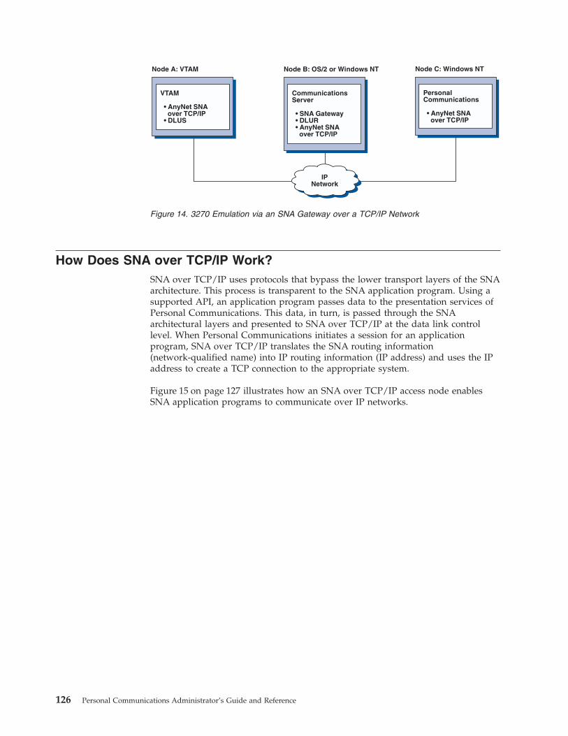
How Does SNA over TCP/IP Work?SNA over TCP/IP uses protocols that bypass the lower transport layers of the SNAarchitecture. This process is transparent to the SNA application program. Using asupported API, an application program passes data to the presentation services ofPersonal Communications. This data, in turn, is passed through the SNAarchitectural layers and presented to SNA over TCP/IP at the data link controllevel. When Personal Communications initiates a session for an applicationprogram, SNA over TCP/IP translates the SNA routing information(network-qualified name) into IP routing information (IP address) and uses the IPaddress to create a TCP connection to the appropriate system.
Figure 15 on page 127 illustrates how an SNA over TCP/IP access node enablesSNA application programs to communicate over IP networks.
IPNetwork
CommunicationsServer
• SNA Gateway• DLUR• AnyNet SNA
over TCP/IP
Node B: OS/2 or Windows NT
PersonalCommunications
• AnyNet SNAover TCP/IP
Node C: Windows NT
VTAM
• AnyNet SNAover TCP/IP
• DLUS
Node A: VTAM
Figure 14. 3270 Emulation via an SNA Gateway over a TCP/IP Network
126 Personal Communications Administrator’s Guide and Reference

The configuration information you define enables SNA over TCP/IP to determine:v Whether to route the data using SNA or to route the data using IPv The IP address associated with the network-qualified LU name
SNA over TCP/IP uses both stream (TCP) and datagram (UDP) sockets that arebound to the well-known port (397). Any information received over this port isrouted to AnyNet.
Mapping SNA Resources to IP AddressesSNA over TCP/IP access nodes must determine the IP address of the partnerbefore an SNA session can be established. The SNA identifier of the partner ismapped to an IP address using the following steps:1. SNA over TCP/IP receives the SNA identifier from Personal Communications
in one of the following formats:v For LU names, netid.lunamev For CP names, netid.cpname
2. SNA over TCP/IP takes the identifier and generates a domain name:v For LU names, luname.netid.snasuffixv For CP names, cpname.netid.snasuffix
Note: The default value for snasuffix is SNA.IBM.COM. For additionalinformation on the SNA domain name suffix, refer to the online help.
Figure 16 on page 128 shows examples of domain names generated by SNAover TCP/IP.
Windows NT
PersonalCommunications
CPI-C
APPC LUA
SNA
SNA Applicationincluding
emulationand print
AnyNet
TCP/IP
Sockets
TCP UDP
IP
DLCs
Figure 15. Structure of SNA over TCP/IP for Personal Communications
Chapter 12. AnyNet SNA over TCP/IP 127

3. SNA over TCP/IP requests that the domain name be translated into an IPaddress.
4. TCP/IP uses the HOSTS file or domain name server to translate the domainname into an IP address (for example, 9.67.192.28).
When the IP network includes SNA over TCP/IP gateways, consider the followingadditional address mapping issue:
If the partner LU can be reached through a gateway, the domain name of thepartner must be mapped to the IP address of the gateway. If there are parallelgateways, the domain name should be mapped to each gateway IP address.
Defining Domain Names and IP AddressesThis section describes the TCP/IP name resolution function, used by AnyNet tomap SNA resources to IP addresses. This function queries both the local HOSTSfile and any domain name servers to convert a domain name (for example,lu1.neta1.sna.ibm.com) into an IP address (for example, 10.1.1.1).
HOSTS FileYou can use TCP/IP HOSTS files to define domain names and IP addressesfor your network. However, as your network becomes larger andmaintaining the HOSTS file on each user workstation becomes tootime-consuming, it is recommended that you use a domain name server.
The HOSTS file lists:v IP addressv Domain namev Other aliases for the domain name
Note: For Windows/NT this resides in the drivers\etc subdirectory ofyour NT system. For Windows 95 and Windows 98, this is in yourWindows system directory.
For example, if your IP address is 10.1.1.1, network ID is NETA1, SNAresource name is LUA1, and SNA domain name suffix is the default(sna.ibm.com), enter the following in your HOSTS file:10.1.1.1 lua1.neta1.sna.ibm.com
Domain Name ServerDomain names and IP addresses can also be defined in the domain nameserver database.
lu1.neta1.sna.ibm.com
netid
domain name
SNA domain name suffixLU name
cp1.neta1.sna.ibm.com
netid
domain name
SNA domain name suffixCP name
Figure 16. Formats of the Domain Names That SNA over TCP/IP Builds
128 Personal Communications Administrator’s Guide and Reference
Each SNA identifier is mapped to a corresponding IP address by a domainname server. The location of these servers is configured in the Networksection of the Control Panel.
For more information on HOSTS files and domain name servers, refer to yourTCP/IP documentation. If your workstation is using the TCP/IP support inWindows 95, Windows 98, Windows NT, Windows Me, Windows 2000, orWindows XP, refer to the online TCP/IP documentation that is included with theWindows 95, Windows 98, Windows NT, Windows Me, Windows 2000, orWindows XP product.
Defining Unique CP Names and Connection Network NamesFor configurations that have two or more SNA over TCP/IP gateways connectingan SNA network with two or more IP networks, you must define a unique SNAcontrol point (CP) name and a unique SNA connection network name for each IPnetwork.
All LUs that reside on access nodes in the IP network appear to reside on a nodewith this CP name.
Use the reverse data file of the domain name server or the HOSTS file to definethe CP name and the connection network name for a given IP network. Map the IPaddress 127.0.0.3 to the CP name and map the IP address 127.0.0.4 to theconnection network name.
The following example shows entries in the reverse data file. For an IP networkwith SNA network ID NETA, CP name MYCPNAME, and connection networkname MYCNET, you would define the following entries:127.0.0.3 NETA.MYCPNAME.127.0.0.4 NETA.MYCNET.
Notes:
1. A period is required at the end of the name only if the definition is in the DNSreverse data file. No period is used in HOSTS file definitions.
2. Do not include the SNA domain name suffix.
The AnyNet SNA over TCP/IP function of Personal Communications provides adefault CP name ($ANYNET.$GWCP) and a default connection network name($ANYNET.$GWCNET). In configurations with one IP network, you can use thedefault by not defining a CP name or a connection network name. Inconfigurations with multiple gateways connecting multiple IP networks, one IPnetwork can use the default. You must, however, define a unique CP name andconnection network name for all other IP networks.
Figure 17 on page 130 shows how to define the CP name and the connectionnetwork name for a configuration with two IP networks. An example is providedin Quick Beginnings.
Chapter 12. AnyNet SNA over TCP/IP 129

Setting and Modifying the Routing Preference ProtocolWhen an SNA application initiates a session, Personal Communications must firstdetermine which transport to use, either SNA, IP, or a combination of the two.
Personal Communications uses the default routing preference for the session unlessthere is a specific routing preference set for the partner LU. PersonalCommunications then sets up a session for the partner LU using the preferredtransport.
If the partner is not available through the preferred transport, PersonalCommunications can reroute the session request over the other available transport,depending on the setting in the routing preference table. For example, if the settingin the routing preference table for the destination LU is nonnative first, PersonalCommunications will attempt to set up the session over TCP/IP. If the partner isnot available through TCP/IP, Personal Communications will route the sessionover SNA. However, if the setting in the routing preference table for thedestination LU is nonnative only, Personal Communications will attempt to set upthe session over TCP/IP. If TCP/IP is not available, Personal Communications willnot route the session over SNA, because the setting allows only PersonalCommunications to use nonnative transport.
The routing preference table is used only for new sessions. Previously existingsessions use the same transport; they are not brought down and rerouted if therouting preference table is changed.
You can set or modify the default routing preference to one of the following:
IP NetworkCPName =$ANYNET.$GWCP
Connection network name =$ANYNET.$GWCNET
IP NetworkCPName = NETB.CPBConnection network name =NETB.CNETB
SNA
SNAover TCP/IPgateway
SNAover TCP/IPgateway
Node A
Node B
reverse address table
127.0.0.3
127.0.0.4
NETB.CPB
NETB.CNETB
(no table, default assumed)
Figure 17. Defining a CP Name and a Connection Network Name
130 Personal Communications Administrator’s Guide and Reference
Native firstRequests are routed over SNA. If no SNA route is available, requests arerouted over TCP/IP.
Nonnative firstRequests are routed over TCP/IP. If no TCP/IP route is available, requestsare routed over SNA.
Native onlyRequests are routed only over SNA. If no SNA route is available, theconnection will fail.
Nonnative onlyRequests are routed only over TCP/IP. If no TCP/IP route is available, theconnection will fail.
Helpful HintsThis section contains helpful hints on tuning, TCP/IP connectivity via SLIP or PPP,and dynamic IP addresses.
TuningIf you can access an LU through multiple SNA over TCP/IP gateways, and youhave mapped that LU name to multiple IP addresses, increase the Connection retryduration and Connection wait time limit when configuring the AnyNet baseparameters. This ensures that TCP attempts to connect to all possible adapters andgateways. It can take as long as 90 seconds for a TCP connection to fail to aninactive IP address.
Connecting to AS/400If you are unable to connect to AS/400 using SNA over TCP/IP, use the followingprocedure:1. Make sure that the ANYNET support on the AS/400 is activated. Issue the
command DSPNETA on the AS/400 and make sure the ANYNET status is yes.2. Edit the HOSTS file on the PC, mapping the IP address to the CP name of the
AS/400.3. Reboot the PC; the SNA over TCP/IP connection is then activated.
Dynamic IP AddressesGenerally, AnyNet SNA over TCP/IP depends on SNA resources (for example, LUnames, CP names, or idblk/num) being statically mapped to IP addresses.However, depending on your configuration and how your connections areinitiated, you might be able to use AnyNet SNA over TCP/IP in environmentswhere IP addresses are dynamically assigned (for example, DHCP).
APPC or CPI-C ApplicationsAn SNA over TCP/IP access node with a dynamically assigned IP address mayalways initiate sessions to another SNA over TCP/IP access node or gateway witha static IP address.
The only way an SNA over TCP/IP access node or gateway with a static IPaddress (node A) can initiate a session to a partner with a dynamic IP address(node B) is:v Node B initiated a session to or through node A first.v The session initiated in Step 1 is still active.
Chapter 12. AnyNet SNA over TCP/IP 131

Dependent LU Applications
Note: The information in this section applies to LU 0, 1, 2, 3, or dependent 6.2applications.
SNA over TCP/IP access nodes with dynamically assigned IP addresses cansupport dependent LU communications if the following criteria are met.v Dependent LU communication is occurring through an SNA gateway either
through:– Communications Manager/2 V5 or later– Communications Server for Windows NT 5.0 or later
v The SNA over TCP/IP access node with a dynamically assigned IP addressinitiates connections to an SNA gateway with a static IP address.
Dependent LU communication through DLUS/DLUR over AnyNet SNA overTCP/IP is not supported if the DLUR node has a dynamically assigned IP address.
AnyNet Configuration ExamplesThis section includes examples of AnyNet running SNA over IP connections.Thefollowing configuration instructions are complete only for the Windows NT andWindows 95 operating systems. In all examples, the SNA domain name suffix isSNA.IBM.COM.
Notes:
1. In the following examples, Windows 95 is shown; Windows 98 can be treatedthe same.
2. Windows NT is shown; Windows 2000 can be treated the same.
For more information about AnyNet as part of Personal Communications, refer tothe 3270 Emulator User’s Reference or 5250 Emulator User’s Reference.
Example 1. 5250 Emulation Over a TCP/IP Network
Follow these steps to establish communication between the Windows 95workstation (Node A) and the AS/400 host (Node B).
CP name: NETA.CPNAME2IP address: 10.2.1.1
IPNetwork
PersonalCommunications
• AnyNet SNAover TCP/IP
Node A: Windows 95
CP name: NETA.CPNAME1IP address: 10.1.1.1
OS/400
• AnyNet SNAover TCP/IP
• TCP/IP
Node B: AS/400 Host
Figure 18. 5250 Emulation Over a TCP/IP Network
132 Personal Communications Administrator’s Guide and Reference

For Windows 95 Node A, do as follows:1. Add the following entries to the local HOSTS file:
10.1.1.1 CPNAME1.NETA.SNA.IBM.COM
2. Create a workstation profile using the Personal Communications configurationtool:a. Click the Start/Configure Session icon; or click Configure from the
Communication menu. The Customize Communication window isdisplayed.
b. Select the following options:v Host: AS/400
v Interface: AnyNet
v Attachment: TCP/IP 5250
c. Click Configure.d. Click Configure Link.e. On the Configure Local System window, enter:
PC Location Name: NETA.CPNAME2
On the Configure Logical Connection Windows, enter:System Location Name: NETA.CPNAME1
f. Save your workstation profile.
For AS/400 Node B, add the following entry to the local HOSTS file:10.2.1.1 CPNAME2.NETA.SNA.IBM.COM
Example 2. Running APPC or CPI-C Applications over aTCP/IP Network
Follow these steps to establish communication between a Windows NT node and aWindows 95 node. Note that in this example, the CP names are used as LU names.
For Windows 95 Node A, do as follows:1. Add the following entry to the local HOSTS file:
172.25.11.2 CP2.NETA.SNA.IBM.COM
LU name: NETA.CP1IP address: 172.25.11.1
IPNetwork
Node A: Windows 95
LU name: NETA.CP2IP address: 172.25.11.2
Node B: Windows NT
Application A
PersonalCommunications
• AnyNet SNAover TCP/IP
Application B
PersonalCommunications
• AnyNet SNAover TCP/IP
Figure 19. Running APPC or CPI-C Applications over a TCP/IP Network
Chapter 12. AnyNet SNA over TCP/IP 133

2. Create a configuration using the Personal Communications configuration tool:a. Click the SNA Node Configuration icon; or click Actions → Launch → SNA
Node Configuration. The Personal Communications SNA NodeConfiguration window is displayed.
b. In the Configuration Options list, choose Configure Node and click New.c. On the Define the Node window on the Basic tab, enter:
Fully qualified CP name: NETA.CP1
Click OK to complete node configuration.d. Choose Configure Devices. In the DLCs list, choose AnyNet SNA/IP and
click New.e. On the Define an AnyNet SNA over TCP/IP Device window on the Basic
tab, enter:SNA domain name suffix: SNA.IBM.COM
f. Click the Routing Preferences tab:Default Routing Preference: Nonnative onlyClick OK to complete configuration of the AnyNet device.
g. From the Personal Communications SNA Node Configuration window, clickFile. Click Save as... and enter the desired file name to save.
For Windows NT Node B, do as follows:1. Add the following entry to the local HOSTS file:
172.25.11.1 CP1.NETA.SNA.IBM.COM
2. Create a configuration using the Personal Communications configuration tool:a. Click the SNA Node Configuration icon; or click Actions → Launch → SNA
Node Configuration. The Personal Communications SNA NodeConfiguration window is displayed.
b. In the Configuration Options list, choose Configure Node and click New.c. On the Define the Node window on the Basic tab, enter:
Fully qualified CP name: NETA.CP2
Click OK to complete node configuration.d. Choose Configure Devices. In the DLCs list, choose AnyNet SNA/IP and
click New.e. On the Define an AnyNet SNA over TCP/IP Device window on the Basic
tab, enter:SNA domain name suffix: SNA.IBM.COM
f. Click the Routing Preferences tab:Default Routing Preference: Nonnative onlyClick OK to complete configuration of the AnyNet device.
g. From the Personal Communications SNA Node Configuration window, clickFile. Click Save as... and enter the desired file name to save.
3. Start Personal Communications on each machine.4. Start your applications (for example APING).
Example 3. APPC3270 Emulation over a TCP/IP Network
134 Personal Communications Administrator’s Guide and Reference
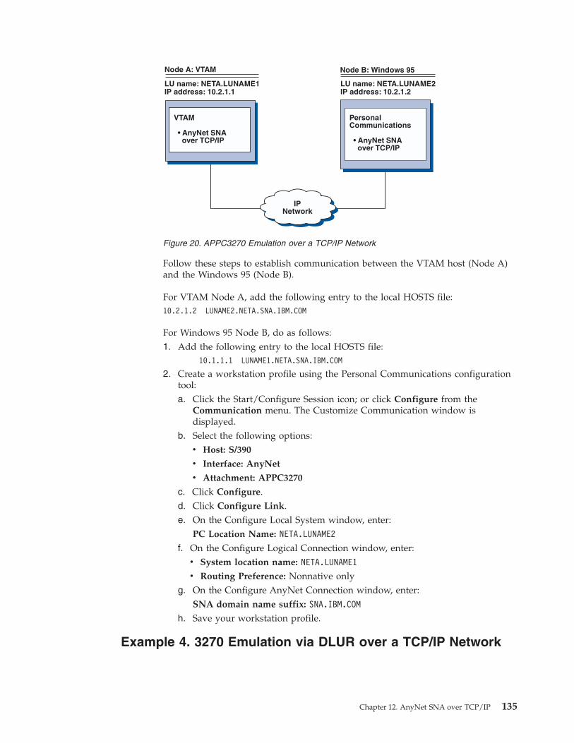
Follow these steps to establish communication between the VTAM host (Node A)and the Windows 95 (Node B).
For VTAM Node A, add the following entry to the local HOSTS file:10.2.1.2 LUNAME2.NETA.SNA.IBM.COM
For Windows 95 Node B, do as follows:1. Add the following entry to the local HOSTS file:
10.1.1.1 LUNAME1.NETA.SNA.IBM.COM
2. Create a workstation profile using the Personal Communications configurationtool:a. Click the Start/Configure Session icon; or click Configure from the
Communication menu. The Customize Communication window isdisplayed.
b. Select the following options:v Host: S/390
v Interface: AnyNet
v Attachment: APPC3270
c. Click Configure.d. Click Configure Link.e. On the Configure Local System window, enter:
PC Location Name: NETA.LUNAME2
f. On the Configure Logical Connection window, enter:v System location name: NETA.LUNAME1
v Routing Preference: Nonnative onlyg. On the Configure AnyNet Connection window, enter:
SNA domain name suffix: SNA.IBM.COM
h. Save your workstation profile.
Example 4. 3270 Emulation via DLUR over a TCP/IP Network
IPNetwork
VTAM
• AnyNet SNAover TCP/IP
Node A: VTAM
PersonalCommunications
• AnyNet SNAover TCP/IP
Node B: Windows 95
LU name: NETA.LUNAME1IP address: 10.2.1.1
LU name: NETA.LUNAME2IP address: 10.2.1.2
Figure 20. APPC3270 Emulation over a TCP/IP Network
Chapter 12. AnyNet SNA over TCP/IP 135

Follow these steps to establish communication between the VTAM Host (Node A)and the Windows 95 workstation (Node B).
For VTAM Node A, add the following entry to the HOSTS file:192.168.7.10 CP2.NETA.SNA.IBM.COM192.168.7.10 DEPLU1.NETA.SNA.IBM.COM
For Windows 95 Node B, do as follows:1. Add the following entry to the local HOSTS file:
192.168.7.8 CP1.NETA.SNA.IBM.COM
2. Create a workstation profile using the Personal Communications configurationtool:a. Click on the Start/Configure Session icon; or click Configure from the
Communication menu. The Customize Communication window isdisplayed.
b. Select the following options:v Host: S/390
v Interface: AnyNet
v Attachment: TCP/IP LU 0,1,2,3 via DLUR
c. Click Configure.d. Click Configure Link.e. On the Configure Local System window, enter:
PC Location Name: NETA.CP2
f. On the Configure DLUR window, enter:v DLUS name: NETA.CP1
v Routing Preference: Nonnative onlyg. On the Configure AnyNet Connection window, enter:
SNA domain name suffix: SNA.IBM.COM
h. Save your workstation profile.
CP name: NETA.CP1IP address: 192.168.7.8
IPNetwork
VTAM
• AnyNet SNAover TCP/IP
• DLUS
Node A: VTAM
CP name: NETA.CP2IP address: 192.168.7.10Dependent LU name: NETA.DEPLU1
PersonalCommunications
• DLUR• AnyNet SNA
over TCP/IP
Node B: Windows 95
Figure 21. 3270 Emulation via DLUR over a TCP/IP Network
136 Personal Communications Administrator’s Guide and Reference

Example 5. 3270 Emulation over a TCP/IP Network via a SNAGateway to a VTAM Host on a SNA Network
For OS/2 (or Windows NT) Node A, add the following entry to the HOSTS file:172.16.5.6 CP1.NETA.SNA.IBM.COM
Follow these steps to establish communication between the Windows 95workstation (Node B) and the VTAM host.
For Windows 95 Node B, do as follows:1. Add the following entry to the local HOSTS file:
172.16.3.4 CP2.NETA.SNA.IBM.COM
2. Create a workstation profile using the Personal Communications configurationtool:a. Click on the Start/Configure Session icon; or click Configure from the
Communication menu. The Customize Communication window isdisplayed.
b. Select the following options:v Host: S/390
v Interface: AnyNet
v Attachment: TCP/IP LU 0,1,2,3
c. Click Configure.d. Click Configure Link.e. On the Configure Local System window, enter:
PC Location Name: NETA.CP1
f. On the Configure AnyNet Connection window, enter:v SNA domain name suffix: SNA.IBM.COM
v Fully qualified CP name: NETA.CP2
g. Save your workstation profile.
CP name: NETA.CP2IP address: 172.16.3.4
IPNetwork
CommunicationsServer
• SNA Gateway• AnyNet SNA
over TCP/IP
Node A: OS/2 or Windows NT
CP name: NETA.CP1IP address: 172.16.5.6
PersonalCommunications
• AnyNet SNAover TCP/IP
Node B: Windows 95
SNAVTAM
PLU
Figure 22. 3270 Emulation over a TCP/IP Network via a SNA Gateway to a VTAM Host on aSNA Network
Chapter 12. AnyNet SNA over TCP/IP 137

Example 6. 3270 Emulation via an SNA Gateway over a TCP/IPNetwork
Follow these steps to establish communication between the Windows 95Workstation (Node C) and the VTAM host (Node A).
For VTAM Node A, add the following entry to the HOSTS file:10.1.1.2 CP2.NETA.SNA.IBM.COM10.1.1.2 DEPLU1.NETA.SNA.IBM.COM
For OS/2 (or Windows NT) Node B, add the following entry to the HOSTS file:10.1.1.3 CP1.NETA.SNA.IBM.COM10.1.1.1 CP3.NETA.SNA.IBM.COM
For Windows 95 Node C, do as follows:1. Add the following entry to the local HOSTS file:
10.1.1.2 CP2.NETA.SNA.IBM.COM
2. Create a workstation profile using the Personal Communications configurationtool:a. Click the Start/Configure Session icon; or click Configure from the
Communication menu. The Customize Communication window isdisplayed.
b. Select the following options:v Host: S/390
v Interface: AnyNet
v Attachment: TCP/IP LU 0,1,2,3
c. Click Configure.d. Click Configure Link.e. On the Configure Local System window, enter:
PC Location Name: NETA.CP1
f. On the Configure AnyNet Connection window, enter:v SNA domain name suffix: SNA.IBM.COM
v Fully qualified CP name: NETA.CP2
g. Save your workstation profile.
CP name: NETA.CP2IP address: 10.1.1.2
IPNetwork
CommunicationsServer
• SNA Gateway• DLUR• AnyNet SNA
over TCP/IP
Node B: OS/2 or Windows NT
CP name: NETA.CP1IP address: 10.1.1.3Dependent LU name: NETA.DEPLU1
PersonalCommunications
• AnyNet SNAover TCP/IP
Node C: Windows 95
CP name: NETA.CP3IP address: 10.1.1.1
VTAM
• AnyNet SNAover TCP/IP
• DLUS
Node A: VTAM
Figure 23. 3270 Emulation via an SNA Gateway over a TCP/IP Network
138 Personal Communications Administrator’s Guide and Reference
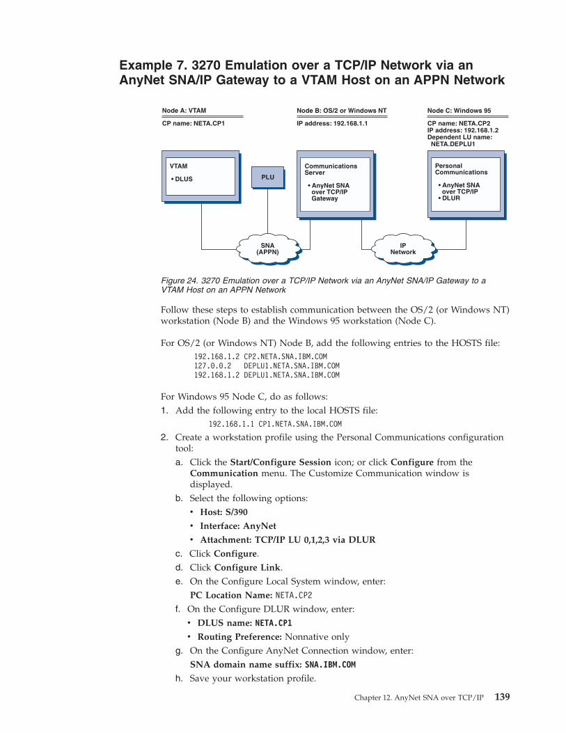
Example 7. 3270 Emulation over a TCP/IP Network via anAnyNet SNA/IP Gateway to a VTAM Host on an APPN Network
Follow these steps to establish communication between the OS/2 (or Windows NT)workstation (Node B) and the Windows 95 workstation (Node C).
For OS/2 (or Windows NT) Node B, add the following entries to the HOSTS file:192.168.1.2 CP2.NETA.SNA.IBM.COM127.0.0.2 DEPLU1.NETA.SNA.IBM.COM192.168.1.2 DEPLU1.NETA.SNA.IBM.COM
For Windows 95 Node C, do as follows:1. Add the following entry to the local HOSTS file:
192.168.1.1 CP1.NETA.SNA.IBM.COM
2. Create a workstation profile using the Personal Communications configurationtool:a. Click the Start/Configure Session icon; or click Configure from the
Communication menu. The Customize Communication window isdisplayed.
b. Select the following options:v Host: S/390
v Interface: AnyNet
v Attachment: TCP/IP LU 0,1,2,3 via DLUR
c. Click Configure.d. Click Configure Link.e. On the Configure Local System window, enter:
PC Location Name: NETA.CP2
f. On the Configure DLUR window, enter:v DLUS name: NETA.CP1
v Routing Preference: Nonnative onlyg. On the Configure AnyNet Connection window, enter:
SNA domain name suffix: SNA.IBM.COM
h. Save your workstation profile.
IP address: 192.168.1.1
IPNetwork
CommunicationsServer
• AnyNet SNAover TCP/IPGateway
Node B: OS/2 or Windows NT
CP name: NETA.CP2IP address: 192.168.1.2Dependent LU name:
NETA.DEPLU1
PersonalCommunications
• AnyNet SNAover TCP/IP
• DLUR
Node C: Windows 95
CP name: NETA.CP1
VTAM
• DLUS
Node A: VTAM
SNA(APPN)
PLU
Figure 24. 3270 Emulation over a TCP/IP Network via an AnyNet SNA/IP Gateway to aVTAM Host on an APPN Network
Chapter 12. AnyNet SNA over TCP/IP 139
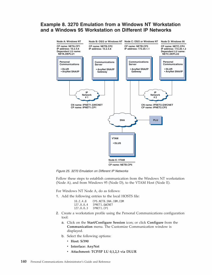
Example 8. 3270 Emulation from a Windows NT Workstationand a Windows 95 Workstation on Different IP Networks
Follow these steps to establish communication from the Windows NT workstation(Node A), and from Windows 95 (Node D), to the VTAM Host (Node E).
For Windows NT Node A, do as follows:1. Add the following entries to the local HOSTS file:
10.2.4.8 CP5.NETB.SNA.IBM.COM127.0.0.4 IPNET1.GWCNET127.0.0.3 IPNET1.CP1
2. Create a workstation profile using the Personal Communications configurationtool:a. Click on the Start/Configure Session icon; or click Configure from the
Communication menu. The Customize Communication window isdisplayed.
b. Select the following options:v Host: S/390
v Interface: AnyNet
v Attachment: TCP/IP LU 0,1,2,3 via DLUR
PLU
CP name: NETB.CP2IP address: 10.2.4.8
Node B: OS/2 or Windows NT
IPNetwork
# 1
CP name: NETA.CP1IP address: 10.2.4.6Dependent LU name:
NETA.DEPLU1
PersonalCommunications
• DLUR• AnyNet SNA/IP
Node A: Windows NT
CP name: NETC.CP4IP address: 172.20.1.2Dependent LU name:
NETC.DEPLU2
Node D: Windows 95
IPNetwork
# 2
CP name: NETB.CP3IP address: 172.20.1.1
Node C: OS/2 or Windows NT
CN name: IPNET1.GWCNETCP name: IPNET1.CP1
CN name: IPNET2.GWCNETCP name: IPNET2.CP2
CommunicationsServer
• AnyNet SNA/IPGateway
SNA
CP name: NETB.CP5
Node E: VTAM
VTAM
• DLUS
CommunicationsServer
• AnyNet SNA/IPGateway
PersonalCommunications
• DLUR• AnyNet SNA/IP
Figure 25. 3270 Emulation on Different IP Networks
140 Personal Communications Administrator’s Guide and Reference

c. Click on Configure.d. Click on Configure Link.e. On the Configure Local System window, enter:
PC Location Name: NETA.CP1
f. On the Configure DLUR window, enter:v DLUS name: NETB.CP5
v Routing Preference: Non-native onlyg. On the Configure AnyNet Connection window, enter:
SNA domain name suffix: SNA.IBM.COM
h. Save your workstation profile.
For OS/2 (or Windows NT) Node B, add the following entries to the HOSTS file:10.2.4.6 CP1.NETA.SNA.IBM.COM127.0.0.2 DEPLU1.NETA.SNA.IBM.COM10.2.4.6 DEPLU1.NETA.SNA.IBM.COM127.0.0.4 IPNET1.GWCNET127.0.0.3 IPNET1.CP1
For OS/2 (or Windows NT) Node C, add the following entries to the HOSTS file:172.20.1.2 CP4.NETC.SNA.IBM.COM127.0.0.2 DEPLU2.NETC.SNA.IBM.COM172.20.1.2 DEPLU2.NETC.SNA.IBM.COM127.0.0.4 IPNET2.GWCNET127.0.0.3 IPNET2.CP2
For Windows 95 Node D, do as follows:1. Add the following entry to the local HOSTS file:
172.20.1.1 CP5.NETB.SNA.IBM.COM127.0.0.4 IPNET2.GWCNET127.0.0.3 IPNET2.CP2
2. Create a workstation profile using the Personal Communications configurationtool:a. Click the Start/Configure Session icon; or click Configure from the
Communication menu. The Customize Communication window isdisplayed.
b. Select the following options:v Host: S/390
v Interface: AnyNet
v Attachment: TCP/IP LU 0,1,2,3 via DLUR
c. Click Configure.d. Click Configure Link.e. On the Configure Local System window, enter:
PC Location Name: NETC.CP4
f. On the Configure DLUR window, enter:v DLUS name: NETB.CP5
v Routing Preference: Nonnative onlyg. On the Configure AnyNet Connection window, enter:
SNA domain name suffix: SNA.IBM.COM
h. Save your workstation profile.
Chapter 12. AnyNet SNA over TCP/IP 141

142 Personal Communications Administrator’s Guide and Reference

Part 4. National Language Support
© Copyright IBM Corp. 1989, 2002 143

144 Personal Communications Administrator’s Guide and Reference
Chapter 13. Multiple-Language Support
Personal Communications Version 5.6 multiple-language support provides thecapability to allow users to interact with more than a single language on theirworkstations. Prior versions allowed for different languages to be displayed inemulator sessions; now, the Windows graphical user interface elements of thePersonal Communications user interface can be tailored to the languages of users,allowing more flexibility in configuring and using Personal Communications.
This chapter provides a basic description of these facilities. Refer to QuickBeginnings for a description of the procedures for changing your configured userinterface language. The particulars of installing the support are described in theCD-ROM Guide to Installation.
OverviewThere are two system-related factors which govern the usage of multiple languagesby Personal Communications users:
System LocaleThis is set in the Windows Regional Settings (Regional Options inWindows 2000 and Regional and Language Options in Windows XP)control panel applet; it determines what system user interface languagescan be viewed.
Language GroupsEach system locale is associated with a language group; some groups haveonly one language; others support several, allowing for simultaneousviewing of applications in more than one language.
System LocaleWhen you choose a language on the Regional Settings (or Options) screen, asystem locale is established as the basis for interacting with the system; Windowsinteractions of certain applications (such as Personal Communications) aregoverned by this setting.
In Windows 2000, you can change the system locale in the Regional Options →General → Set Default... → Select System Locale dialog. For Windows XP, PersonalCommunications uses the settings specified in Regional and Language →Advanced → Language for non-Unicode programs.
Notes:
1. Windows common dialogs, such as file open and print, may not change tomatch the system locale; they will be displayed in the language chosen whenWindows was installed.
2. The actions needed to switch system locales depend on the languages installedand the version of Windows. Refer to your Windows documentation for details.
Language GroupsThe system locale set when Windows is started determines which Windows/ANSIcode page is used by applications; in turn, this code page determines whichlanguage group an application can use. The language groups and languagessupported for Personal Communications user interface are:
© Copyright IBM Corp. 1989, 2002 145

CyrillicRussian
JapaneseJapanese
Latin 1
v Brazilian-Portuguesev Danishv Dutchv Englishv Finnishv Frenchv Germanv Italianv Norwegianv Portuguesev Spanishv Swedish
Latin 2
v Czechv Hungarianv Polishv Slovenian
TurkishTurkish
Notes:
1. For Windows XP, most language groups are installed by default. You canspecify supplemental language support.
2. English text can be displayed for any system locale without significantcorruption. Therefore, English is an implicit member of each language group.
3. There are additional languages supported for host emulation sessions; thesegroups only concern user interface language.
Personal Communications User Interface LanguagesIt is important to understand how Personal Communications uses the capabilityfor supporting multiple languages. Like other applications, PersonalCommunications can use any language within the language group for which thecurrent system locale is set. As an administrator, you have the ability to changethat locale, using the Windows Regional Settings control panel applet.
There are several considerations to keep in mind:v There is a default Personal Communications user interface language; this is set
at installation, and applies to every user of the Windows system.
Note: This default is set to match the Windows user default locale.v The Personal Communications user interface language is a preference that is
stored per user; thus, a shared workstation can support users of differentlanguages.
146 Personal Communications Administrator’s Guide and Reference

v If a user does not have a user interface language preference defined, PersonalCommunications uses the Personal Communications default language for thatmachine.
v If the user’s language preference cannot be displayed (because of a languagegroup mismatch) the user interface is in the Personal Communications defaultlanguage; a warning is displayed.
v If the Personal Communications default language is incompatible with thesystem language, English is used as the default.
v Each user in a client/server or Windows Terminal Server (WTS) environmentscan have his own Personal Communications user interface language.
Multiple SessionsIt is possible to open multiple Personal Communications emulation sessionssimultaneously; in previous versions of Personal Communications these sessionscould interact with hosts of different languages.
With Version 5.6 it is also possible to have simultaneous sessions with differentuser interface languages; this is only possible for languages within a languagegroup. In order to do this, you start a session in one language, then change thePersonal Communications configuration to another language; when you then starta new session, it will use the newly selected language.
Other ConsiderationsTo prevent the generation of log files in several languages the PersonalCommunications log file is recorded in the default Personal Communications userinterface language.
Some of the Personal Communications components (such as LLC2 drivers) do notrequire multiple-language support; they only use the default PersonalCommunications language.
Some Personal Communications components (the keyboard customizer, keypad,play/record, copy/paste and macro components, for example) record, store, andinsert language-sensitive text into Personal Communications sessions. It should benoted that text created in one language group may be corrupted and meaninglesswhen inserted in a session running under another language group. For instance,keyboard customizer text created on a Japanese Personal Communicationsconfiguration will not be readable on a French configuration.
Chapter 13. Multiple-Language Support 147

148 Personal Communications Administrator’s Guide and Reference
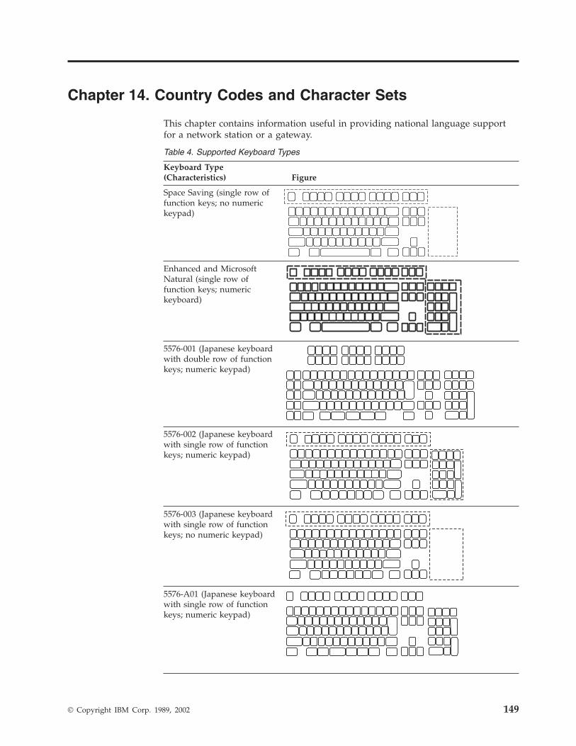
Chapter 14. Country Codes and Character Sets
This chapter contains information useful in providing national language supportfor a network station or a gateway.
Table 4. Supported Keyboard Types
Keyboard Type(Characteristics) Figure
Space Saving (single row offunction keys; no numerickeypad)
Enhanced and MicrosoftNatural (single row offunction keys; numerickeyboard)
5576-001 (Japanese keyboardwith double row of functionkeys; numeric keypad)
5576-002 (Japanese keyboardwith single row of functionkeys; numeric keypad)
5576-003 (Japanese keyboardwith single row of functionkeys; no numeric keypad)
5576-A01 (Japanese keyboardwith single row of functionkeys; numeric keypad)
© Copyright IBM Corp. 1989, 2002 149
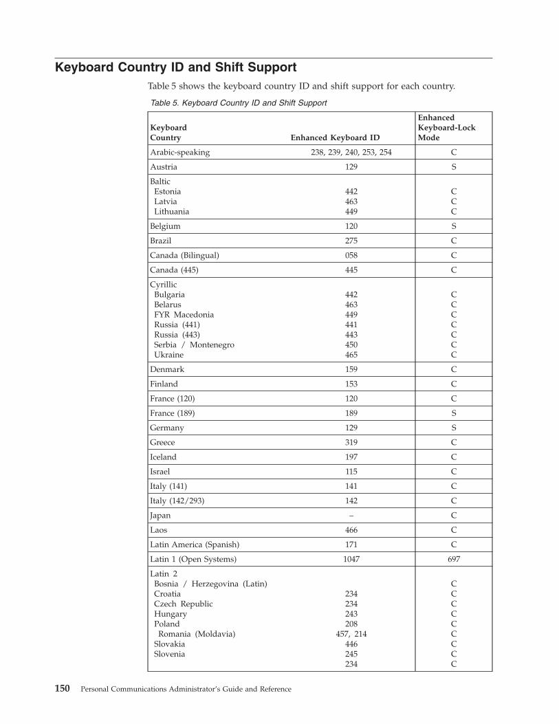
Keyboard Country ID and Shift SupportTable 5 shows the keyboard country ID and shift support for each country.
Table 5. Keyboard Country ID and Shift Support
KeyboardCountry Enhanced Keyboard ID
EnhancedKeyboard-LockMode
Arabic-speaking 238, 239, 240, 253, 254 C
Austria 129 S
BalticEstoniaLatviaLithuania
442463449
CCC
Belgium 120 S
Brazil 275 C
Canada (Bilingual) 058 C
Canada (445) 445 C
CyrillicBulgariaBelarusFYR MacedoniaRussia (441)Russia (443)Serbia / MontenegroUkraine
442463449441443450465
CCCCCCC
Denmark 159 C
Finland 153 C
France (120) 120 C
France (189) 189 S
Germany 129 S
Greece 319 C
Iceland 197 C
Israel 115 C
Italy (141) 141 C
Italy (142/293) 142 C
Japan – C
Laos 466 C
Latin America (Spanish) 171 C
Latin 1 (Open Systems) 1047 697
Latin 2Bosnia / Herzegovina (Latin)CroatiaCzech RepublicHungaryPoland
Romania (Moldavia)SlovakiaSlovenia
234234243208
457, 214446245234
CCCCCCCCC
150 Personal Communications Administrator’s Guide and Reference
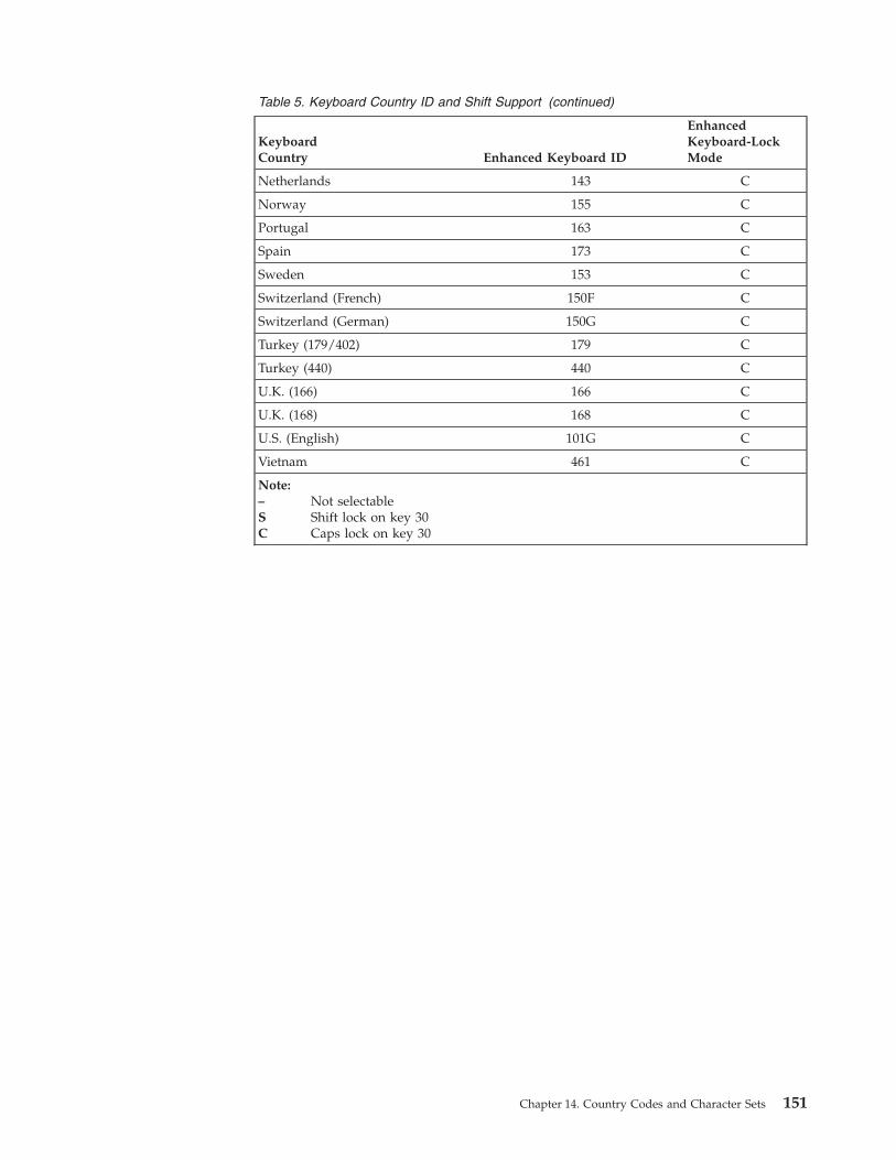
Table 5. Keyboard Country ID and Shift Support (continued)
KeyboardCountry Enhanced Keyboard ID
EnhancedKeyboard-LockMode
Netherlands 143 C
Norway 155 C
Portugal 163 C
Spain 173 C
Sweden 153 C
Switzerland (French) 150F C
Switzerland (German) 150G C
Turkey (179/402) 179 C
Turkey (440) 440 C
U.K. (166) 166 C
U.K. (168) 168 C
U.S. (English) 101G C
Vietnam 461 C
Note:– Not selectableS Shift lock on key 30C Caps lock on key 30
Chapter 14. Country Codes and Character Sets 151
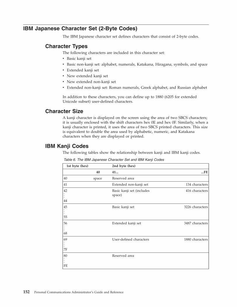
IBM Japanese Character Set (2-Byte Codes)The IBM Japanese character set defines characters that consist of 2-byte codes.
Character TypesThe following characters are included in this character set:v Basic kanji setv Basic non-kanji set: alphabet, numerals, Katakana, Hiragana, symbols, and spacev Extended kanji setv New extended kanji setv New extended non-kanji setv Extended non-kanji set: Roman numerals, Greek alphabet, and Russian alphabet
In addition to these characters, you can define up to 1880 (6205 for extendedUnicode subset) user-defined characters.
Character SizeA kanji character is displayed on the screen using the area of two SBCS characters;it is usually enclosed with the shift characters hex 0E and hex 0F. Similarly, when akanji character is printed, it uses the area of two SBCS printed characters. This sizeis equivalent to double the area used by alphabetic, numeric, and Katakanacharacters when they are displayed or printed.
IBM Kanji CodesThe following tables show the relationship between kanji and IBM kanji codes.
Table 6. The IBM Japanese Character Set and IBM Kanji Codes
1st byte (hex) 2nd byte (hex)
40 41... ...FE
40 space Reserved area
41 Extended non-kanji set 134 characters
42...44
Basic kanji set (includesspace)
416 characters
45...55
Basic kanji set 3226 characters
56...68
Extended kanji set 3487 characters
69...7F
User-defined characters 1880 characters
80...FE
Reserved area
152 Personal Communications Administrator’s Guide and Reference
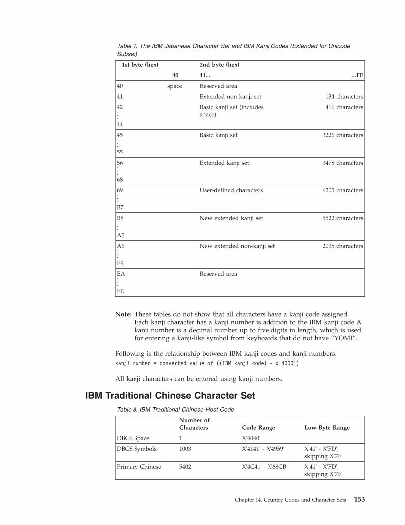
Table 7. The IBM Japanese Character Set and IBM Kanji Codes (Extended for UnicodeSubset)
1st byte (hex) 2nd byte (hex)
40 41... ...FE
40 space Reserved area
41 Extended non-kanji set 134 characters
42...44
Basic kanji set (includesspace)
416 characters
45...55
Basic kanji set 3226 characters
56...68
Extended kanji set 3478 characters
69...B7
User-defined characters 6205 characters
B8...A5
New extended kanji set 5522 characters
A6...E9
New extended non-kanji set 2035 characters
EA...FE
Reserved area
Note: These tables do not show that all characters have a kanji code assigned.Each kanji character has a kanji number is addition to the IBM kanji code Akanji number is a decimal number up to five digits in length, which is usedfor entering a kanji-like symbol from keyboards that do not have “YOMI”.
Following is the relationship between IBM kanji codes and kanji numbers:kanji number = converted value of ((IBM kanji code) - x’4000’)
All kanji characters can be entered using kanji numbers.
IBM Traditional Chinese Character SetTable 8. IBM Traditional Chinese Host Code
Number ofCharacters Code Range Low-Byte Range
DBCS Space 1 X'4040'
DBCS Symbols 1003 X'4141' - X'4959' X'41' - X'FD',skipping X'7F'
Primary Chinese 5402 X'4C41' - X'68CB' X'41' - X'FD',skipping X'7F'
Chapter 14. Country Codes and Character Sets 153

Table 8. IBM Traditional Chinese Host Code (continued)
Number ofCharacters Code Range Low-Byte Range
Secondary Chinese 7654 X'6941' - X'91C7' X'41' - X'FD',skipping X'7F'
User-Defined Area 6204 X'C241' - X'E2FD' X'41' - X'FD',skipping X'7F'
IBM Simplified Chinese Character Set, GBK CodeTable 9. IBM Simplified Chinese Character Set, GBK Code
Number ofCharacters Host Code Range PC Code Range
DBCS Space 1 X'4040' X'A1A1'
GB 2312-80Non-Chinese CharacterSet
(GBK/1)
X'4141'-X'47FE' (737) X'A1A1'-X'A9FE'(846)
GB 2312-80 ChineseCharacter Set
(GBK/2)
X'4841'-X'6CFE'(6763)
X'B0A1'-X'F7FE'(6768)
ISO 10646-1 CJK unifiedideographs
(GBK/3)
6080 X'8141'-X'A0FE',X'A141'-X'A181'
X'8140'-X'A0FE'(Note 1)
ISO 10646-1 CJK unifiedideographs ISO 10646-1CJK compatibility
(GBK/4)
8160 X'A182'-X'A1FE',X'A241'-X'CCFE',X'CE41'-X'CEFE'
X'AA40'-X'FEA0'(Note 1)
Big-5 SymbolCompatibilityIdeographic StructureSymbols
(GBK/5)
X'CD41'-X'CDFE'(148)
X'A840'-X'A9A0'(192) (Note 1)
User DefinableCharacters Area
(UDC 1 to 3)
1894 X'7641'-X'80FE' X'AAA1'-X'AFFE',X'F8A1'-X'FEFE',X'A140'-X'A7A0'(Note 1)
Note 1: X'7F' of second byte is excluded.
IBM Hangeul Character SetTable 10. IBM Hangeul Host Code (833)
Number ofCharacters Code Range Low-Byte Range
DBCS Space 1 X'4040'
DBCS Symbols 939 X'4141' - X'4BFD' X'41' - X'FD',skipping X'7F'
154 Personal Communications Administrator’s Guide and Reference

Table 10. IBM Hangeul Host Code (833) (continued)
Number ofCharacters Code Range Low-Byte Range
Hanja Set 5265 X'5041' - X'6C45' X'41' - X'FD',skipping X'7F'
Hangeul and JamoSet
2672 X'8441' - X'D3B7' X'41' - X'FD',skipping X'7F'
User-Defined Area 1880 X'D441' - X'DDFD' X'41' - X'FD',skipping X'7F'
Table 11. IBM Hangeul Host Code (1364)
Number ofCharacters Code Range Low-Byte Range
DBCS Space 1 X'4040'
Non-Hangeul/HanjaSet
1181 X'4141' - X'4E92' X'41' - X'FE'
Hanja Set 5265 X'5041' - X'6C45' X'41' - X'FE'
Hangeul and JamoSet
11224 X'8441' - X'D3BD' X'41' - X'FE'
User-Defined Area 1880 X'D441' - X'DDFD' X'41' - X'FE'
Thai Language Support
Thai Display Mode SelectionSelect menu Appearance on emulator session, and then select Thai ComposeMode...
Switching Keyboard Between Thai and LatinPress either Alt+left shift or Alt+right shift to toggle the keyboard between Thaiand Latin.
Language Shift StatusThe status line of each emulator session shows a language shift indicator. Ifkeyboard is in Thai language shift, an indicator TH will appear in the status line.
Thai Display Composed ModeMode 1 - Non-compose mode
No character composition occurs in this mode.
Mode 2 - Composed modeThai characters are auto-composed in this mode. No column realignment isperformed.
Mode 3 - Composed with space alignmentIn this mode of composing, three consecutive spaces cause columnrealignment. The realignment occurs whenever composing routine findsthree consecutive spaces. Thus if all fields have at least three trailingspaces, then all fields of all records will be properly aligned.
Mode 4 - Composed with EOF alignmentIn this mode of composing, the EOF character (Hexadecimal ’EA’) alsocauses column realignment. Whenever the composing routine finds a single
Chapter 14. Country Codes and Character Sets 155

EOF, it deletes the EOF and performs column realignment. If twoconsecutive EOFs are found, no realignment occurs, one EOF is deleted,and one EOF is treated as data.
Mode 5 - Composed with space and EOF alignmentThis mode of composing performs the column realignment function ofboth mode 3 and mode 4.
Printer Space AdjustmentIf your printer needs space adjustment for Thai printing, add the followingstatement to PCSWIN.INI, which resides in the user-class application datadirectory:[Thai]PrintAdjust=x
The value of x can be:
0 no adjustment (same as no PrintAdjust statement)
1 Perform adjustment when found three consecutive spaces
2 Perform adjustment when found EOF character
3 Perform adjustment when found three consecutive spaces or EOF character(combine 1 and 2)
Thai Scalable (Truetype) Font support on PrintersPersonal Communications provides a Thai Truetype font, ThaiPhuket. To print Thaicharacters, you can install a Thai scalable (Truetype) font as follows:1. Open the Control Panel Folder.
a. Click Start on the task bar.b. Move pointer to Settings and click Control Panel.
2. Open the Fonts Folder (Double-click the Fonts icon).3. On the file menu, select Install New Font.4. Click the drive and folder where Personal Communications is installed.5. Double-click on ThaiPhuket.
156 Personal Communications Administrator’s Guide and Reference
Chapter 15. Bidirectional Language Support (Arabic andHebrew)
Considerations for PrintingPDT printing mode requires the IBM Arabic 864 code page font to be installed, andthe IBM Hebrew 862 code page font for Hebrew printing.
Printing in ArabicTo enable printing in Arabic, you need to do the following :v For 5250 sessions, using Host Print Transform, you should install the 864 Arabic
printer fonts or the AFP fonts on the AS/400 system.v For 3270 sessions, using PDF files, do the following:
1. Install the 864 Arabic printer fonts.2. Modify the PDF files as follows:
a. Define the escape sequences of the fonts that you want to use, as in thefollowing example./* Naseem ( 1 0 V ( s 0 p 1 5 h 9 v 0 s 0 b 3 T */NSM EQU 1B 28 31 30 56 1B 28 73 30 70 31 35 68 39 76 30 73 30 62 33 54
Note: You can get the font escape sequences by printing out the fontnames from the printer menus.
b. Add the escape sequence of the font that you want to use to theSTART_JOB escape sequence, as in the following example.START_JOB=CUL CBP NSM /* Switch to Arabic Font */
3. Compile the PDF to get the PDT file.
DAT File for 5250 ArabicFor Arabic 5250 print sessions, selecting the 420 host code page prompts PersonalCommunications to load the PCSPDA.DAT file. This file ensures that thehost-specified fonts map properly to the Typing Arabic print font.
If the 037 (U.S.) host code page is selected in a Win32 OS session, the PCSPD.SAMfile is loaded automatically. This file replaces the Courier font with Courier New.For 5250 sessions in OS/2, Personal Communications uses the original PCSPD.DATfile, since Euro support is implemented in Courier in OS/2, not in Courier New (asin Windows).
The user can specify the DAT file using the .ws parameterDATFILE=xxxx
where xxxx is the name of the preferred DAT file.
© Copyright IBM Corp. 1989, 2002 157

Bidirectional Arabic Support
LimitationsThe Bidirectional Text Assist Function is not supported in the PersonalCommunications AS/400 component. As a result, the user cannot run BidirectionalOfficeVision/400™.
Installation TipsTo set up an Arabic workstation, do the following:1. Select 420 Arabic Speaking as the host code page in the Customize
Communication panel.2. Select Arabic Speaking as the keyboard layout.3. In the Select Display Font panel, choose ARB3270 at the Automatic Sizing list
box or at the Fixed size font selection.4. In the API Settings panel, select 864 as the DDE/EHLLAPI PC code page.5. Choose Typing Arabic as the font in the Page Setup panel.
Note: For Personal Communications for Windows 95 you can also selectARB3270 for printers with drivers that allow bitmap fonts. For example,printing through PDT requires the IBM Arabic 864 font to be availableon the printer.
To set up for Numeric Swapping or Symmetric Swapping:1. Select Display Setup from the Edit → Preferences → Appearance pull-down list.2. Select Swapping from the list box at the left, where the settings for numerics
and symmetric characters is displayed. Changes are immediately reflected onthe active session.
Note: Numeric Swapping is a 3270-only feature. This function will not beselectable if the session is an AS/400 session.
The supported Arabic fonts are:v ARB3270, which is found in the PCSANSIA.FON, or MFIANSIA.FON. To use
the MFIANSIA.FON:1. Rename the file PCSANSIA.FON to PCSANSIA.ORG.2. Copy MFIANSIA.FON to PCSANSIA.FON.
v Typing Arabic, which is found in the file TYPEARB.TTF.
The Arabic font files are located on the product CD-ROM in the FONTsubdirectory.
Bidirectional Keyboard Functions for 3270The keys unique to Bidirectional 3270 are:v Language selection: This function is activated by the key combination Alt+Shift
and allows you to change the language layer. If the language layer is Latin,pressing the Alt+RightShift key combination changes the language layer toArabic. If the language layer is Arabic, pressing the Alt+LeftShift keycombination changes the language layer to Latin.
v Screen Reverse: This function is activated by the key combination Alt+NewLineand reverses the screen image. If the screen orientation is left-to-right, pressing
158 Personal Communications Administrator’s Guide and Reference
this key combination reverses the screen image right-to-left. If the screenorientation is right-to-left, pressing this key combination reverses the screenimage to left-to-right.Note that the operator information area is not reversed by this operation.When the screen orientation is changed, the language layer is changed to thedefault language of the new screen orientation. If the screen is reversed toright-to-left, then the language is changed to Arabic. If the screen is reversed toleft-to-right, then the language is changed to one using Latin characters.If the swapping of symmetric characters is enabled, the inversion of the screencauses directional characters to be replaced by their counterparts.If the swapping of numeric characters is enabled, the inversion of the screencauses Hindi numerals to be replaced by their Arabic counterparts and theArabic numerals to be replaced by their Hindi counterparts.
v Field Reverse: This function is activated by the key combination Alt+NumLockand toggles the field orientation to either opposite to or the same as the screenorientation. The text in the field is not inverted. The cursor orientation is setequal to the new field orientation and the language layer is selected accordingly.If the cursor is in the first logical position of a field or line, when you select thefield reverse function, the cursor skips to the other side of that field or line,which becomes the first logical position. If the cursor was not in the firstposition of the field or line, when selecting the field reverse function, the cursorremains in its position and allows natural and correct editing of existing text.
v Auto Field Reverse: This function is activated by the key combinationAlt+NumPad5, which toggles the auto field reverse mode for the current screenorientation.Auto field reverse affects the automatic selection of the field orientation ofunprotected fields:– When auto field reverse is disabled, upon initial entry to a field (whether
numeric or alphanumeric), the field orientation is always set equal to thescreen orientation.
– When auto field reverse is enabled, upon initial entry to an alphanumericfield, the field orientation will be set to right-to-left (for both left-to-right andright-to-left screen orientations).
– When auto field reverse is enabled, upon initial entry to a numeric field, thefield orientation will be set to left-to-right (for both left-to-right andright-to-left screen orientations).
v Push/End Push: This function is activated by the key combinationShift+NumLock and allows the entering and editing of text whose direction isopposite from the field direction. When this function is activated, the cursororientation is reversed, the language layer is changed accordingly, and a pushsegment is created.The PUSH function has two secondary modes:– Boundary mode: This mode is activated upon entering push mode. In this
mode, the cursor remains in its position, and the typing of additionalcharacters pushes the text in the direction opposite from the field direction. Toindicate this boundary mode, the cursor has a block shape.
– Edit mode: This mode is activated when the cursor is moved from itsboundary position into the PUSH SEGMENT area. In this mode, you can editthe text within the PUSH segment, while typing in the field’s naturaldirection.
Chapter 15. Bidirectional Language Support (Arabic and Hebrew) 159
END PUSH, activated by the Shift+NumLock key sequence, terminates the pushmode.
Note: In Windows mode, END PUSH is activated by the Shift+Numpad/ keysequence.
The cursor jumps to the end of the PUSH segment, and its direction changes tothe original direction. You can also perform END PUSH by pressing any fieldexit keys (for example, Cursor Up or Cursor Down) or an AID key (for example,Enter)
v AutoPush: This function is activated by the key combination Alt+NumPad/ andassists the terminal operator in typing mixed left-to-right and right-to-left text.When enabled, reversed segments are automatically initiated and terminated,according to the entered character or the selected language layer. This moderelieves the operator from manually pressing Push, as it is automaticallyinvoked.– In right-to-left fields, typing a digit or a Latin letter causes the automatic
initiation of Push, without language change. Further Latin letters or digitswill continue the push mode; any other character automatically terminatespush mode. This feature allows you to type Arabic text with imbeddednumbers or Latin words without using Push/End Push.
– In left-to-right fields, typing an Arabic character or special character causesthe automatic initiation of Push, without language change. Typing any digitor Latin character causes the automatic termination of the mode. This allowsthe user to type Latin text with imbedded Arabic words using language layerselection rather than Push/End Push.
Arabic Character Shape Selection FunctionsThere are five shape selection keys: one for Contextual Shape Determination (CSD),and 4 for Specific Shaping modes (Base/Isolated, Initial, Middle, Final). The defaultShaping Mode is CSD.
The keys unique to Bidirectional 3270 are:v Contextual Shape Determination (CSD) key: Pressing this key sets the shaping
mode to Contextual Shape Determination (CSD), which is the default. Note thatcontextual shape determination is performed only for right-to-left text entered ormodified by the operator. This key toggles between CSD and Base mode.Pressing any of the Specific shape selection keys disables CSD.The character Alef-Madda
in the operator information area indicates that CSD is selected.
This function is initiated by the key combination Alt+NumPad4.v Specific Shape Selection keys:
– Base/Isolated: initiated by the key combination Alt+NumPad2– Initial: initiated by the key combination Alt+NumPad1– Final: initiated by the key combination Alt+NumPad7– Middle: initiated by the key combination Alt+NumPad8
Pressing one of the above keys disables CSD, and sets shaping mode to theselected value. Arabic letters typed from then on will have the selected shape.
160 Personal Communications Administrator’s Guide and Reference
Note: Some Arabic characters do not have middle, initial, or final shapes. In thiscase, if the user enters one of those characters where the requested shapedoes not exist, then the closest shape is selected according to thefollowing rules:– Instead of initial, isolated is selected.– Instead of final, isolated is selected.– Instead of middle, final (if it exists) or isolated is selected.
The selected Shaping Mode is shown in the operator information area:– Isolated GHEIN
indicates Base/Isolated Shaping Mode– Initial GHEIN
indicates Initial Shaping Mode– Middle GHEIN
indicates Middle Shaping Mode– Final GHEIN
indicates Final Shaping Modev Field Shape key: Pressing the key combination Alt+NumPad+ causes the
shaping of the Arabic data present in the current field or line. The cursorposition remains unchanged.
v Field De-Shape key: The key combination Alt+NumPad Enter de-shapes theArabic data present in the current field or line. All Arabic letters are convertedto their Base/Isolated shapes.
Personal Communications AS/400The keys unique to Bidirectional PC400 are:v Language selection: This function is activated by the key combination Alt+Shift
and allows the changing of the language layer. If the language layer is Latin, bypressing the Alt+RightShift key combination, the language layer will change toArabic. If the language layer is Arabic, by pressing the Alt+LeftShift keycombination, the language layer will change to Latin.
v Screen Reverse: This function is activated by the key combination Alt+NewLineand reverses the screen image. If the screen orientation is left-to-right, bypressing this key combination the screen image will be reversed to right-to-left.If the screen orientation is right-to-left, pressing this key combination reversesthe screen image to left-to-right.Note that the operator information area is not reversed by this operation.When the screen orientation is changed, the language layer is changed to thedefault language of the new screen orientation. If the screen is reversed toright-to-left, the language is changed to Arabic. If the screen is reversed toleft-to-right, the language is changed to one using Latin characters.
Chapter 15. Bidirectional Language Support (Arabic and Hebrew) 161
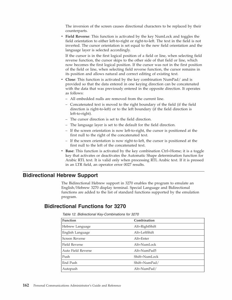
The inversion of the screen causes directional characters to be replaced by theircounterparts.
v Field Reverse: This function is activated by the key NumLock and toggles thefield orientation to either left-to-right or right-to-left. The text in the field is notinverted. The cursor orientation is set equal to the new field orientation and thelanguage layer is selected accordingly.If the cursor is in the first logical position of a field or line, when selecting fieldreverse function, the cursor skips to the other side of that field or line, whichnow becomes the first logical position. If the cursor was not in the first positionof the field or line, when selecting field reverse function, the cursor remains inits position and allows natural and correct editing of existing text.
v Close: This function is activated by the key combination NumPad/ and isprovided so that the data entered in one keying direction can be concatenatedwith the data that was previously entered in the opposite direction. It operatesas follows:– All embedded nulls are removed from the current line.– Concatenated text is moved to the right boundary of the field (if the field
direction is right-to-left) or to the left boundary (if the field direction isleft-to-right).
– The cursor direction is set to the field direction.– The language layer is set to the default for the field direction.– If the screen orientation is now left-to-right, the cursor is positioned at the
first null to the right of the concatenated text.– If the screen orientation is now right-to-left, the cursor is positioned at the
first null to the left of the concatenated text.v Base: This function is activated by the key combination Ctrl+Home; it is a toggle
key that activates or deactivates the Automatic Shape determination function forArabic RTL text. It is valid only when processing RTL Arabic text. If it is pressedin an LTR field, an operator error 0027 results.
Bidirectional Hebrew SupportThe Bidirectional Hebrew support in 3270 enables the program to emulate anEnglish/Hebrew 3270 display terminal. Special Language and Bidirectionalfunctions are added to the list of standard functions supported by the emulationprogram.
Bidirectional Functions for 3270Table 12. Bidirectional Key-Combinations for 3270
Function Combination
Hebrew Language Alt+RightShift
English Language Alt+LeftShift
Screen Reverse Alt+Enter
Field Reverse Alt+NumLock
Auto Field Reverse Alt+NumPad5
Push Shift+NumLock
End Push Shift+NumPad/
Autopush Alt+NumPad/
162 Personal Communications Administrator’s Guide and Reference
The 3270 host system can run as a native Windows application. The layout anduser interface functions in the Windows-based product conform to the IBM userinterface standard (SAA/CUA®); they are similar to the layout and functionsimplemented in other IBM products (for example, OS/2).v Language Selection: The key combination Alt+Shift allows you to change the
language layer. If the language layer is Latin, pressing Alt+RightShift changesthe language layer to Hebrew. If the language layer is Hebrew, pressingAlt+LeftShift changes the language layer to Latin.
v Screen Reverse: This function, activated by the Alt+Enter key sequence, reversesthe screen image. If the screen direction is left-to-right, the screen image isinverted and displayed from right-to-left. Pressing this hotkey again returns thescreen to its original direction, left-to-right. When the screen orientation ischanged, the language layer is changed to the default language of the newscreen orientation. If the screen is changed to right-to-left, the language changesto Hebrew. If the screen is changed to left-to-right, the language changes toLatin.Note that the status line (OIA) never reverses. It always displays from left toright.
v Field Reverse: In most cases, the field direction is the same as the general screendirection. However, sometimes it is necessary to have a field whose direction isthe opposite of the screen direction. The Field Reverse function, activated by theAlt+NumLock key sequence, allows such transitions. When this function isactivated, the typing direction is reversed, but the existing text in the field andthe screen image does not change. This function creates a temporary changewhich stays in effect as long as the cursor remains within the field, or until FieldReverse is activated again.If the function is activated while the cursor is at the beginning of a line or field,the cursor jumps to the end of the line or field, so that the reversed field beginslogically from that position. Otherwise, the cursor remains in its position andallows natural and correct editing of existing texts whose direction is theopposite of the screen direction.
v Auto Field Reverse: This function sets the field orientation for you, when youare entering data for mixed applications (Hebrew and English). This is done byautomatically activating the Field Reverse function. The Auto Field Reversemode is activated by the Alt+NumPad5 key sequence, and can be appliedindependently for each screen orientation, left-to-right or right-to-left.– If the Auto Field Reverse option is activated on a right-to-left screen, the Field
Reverse function is automatically activated every time the cursor moves to anumeric field. The cursor then jumps to the leftmost position of the numericfield, to allow left-to-right typing of numbers.
– If the Auto Field Reverse option is activated on a left-to-right screen, the FieldReverse function is automatically activated only when the cursor moves to analphanumeric field. The cursor then jumps to the rightmost position of thefield, to allow right-to-left typing of Hebrew.
Initially, the Auto Field Reverse option is enabled when the screen direction isright-to-left, and is not enabled when the screen direction is left-to-right. Toterminate the Auto Field Reverse mode, press Alt+NumPad5 again.
v Push and End Push: These functions allow you to type or edit text whosedirection is the opposite of the field direction. When this function is activatedthe cursor orientation is reversed, the language layer is changed accordingly, anda push segment is created.
Chapter 15. Bidirectional Language Support (Arabic and Hebrew) 163

The Push function is activated by the Shift+NumLock key sequence. The Pushfunction has two secondary modes:– Boundary Mode: This mode is activated upon entering the Push mode. In this
mode, the cursor remains in its position, and the typing of additionalcharacters pushes the text in the direction opposite to the field direction. Toindicate this boundary mode, the cursor shape is changed.
– Edit Mode: This mode is activated when the cursor is moved from itsboundary position into the Push Segment area. In this mode, you can changethe text within the Push segment, while typing in the text’s natural direction.
End Push, activated by the Shift+NumPad/ key sequence, terminates thetemporary mode. The cursor jumps to the end of the Push segment, and itsdirection reverts to that of the field.
v Autopush: The Autopush mode makes work easier and more efficient whentyping Hebrew and English mixed text. When this mode is enabled, reversesegments initiate and terminate automatically, according to the entered characteror the selected language layer. It relieves the operator from manually selectingPush and End Push. Autopush is especially useful for typing digits in Hebrewfields (right-to-left fields). The Autopush mode is activated by the Alt+NumPad/key sequence; it can be applied independently to fields whose direction isleft-to-right or right-to-left. In this mode, the Push and End Push functions areautomatically activated according to the language of the text being typed. Thereis no need to worry about activating and terminating the Push mode manually.– In right-to-left fields, typing a digit or a Latin letter causes the automatic
initiation of Push, without language change. Additional Latin letters or digitswill continue the push mode; any other character automatically terminatespush mode. This feature allows you to type Hebrew text with imbeddednumbers or Latin words without using Push/End Push.
– In left-to-right fields, typing a Hebrew character causes the automaticinitiation of Push. Typing any digit or Latin character causes the automatictermination of the mode. This allows the user to type Latin text withimbedded Hebrew words by using language layer selection rather thanPush/End Push.
Keyboard LayoutTwo Hebrew keyboard templates (Bulletin and Old Code) are supplied with theproduct. The Old-Code template is similar to the Bulletin template, with thefollowing exceptions:v Shift of ″6″ (s-6) produces the Greek Delta symbol (ASCII 235, hex EB),
representing the old Israeli Lira, instead of the regular Cent symbol.v Shift of ″7″ (s-7) does not produce anything (the Ampersand symbol is not
available in Old Code).v In English language mode, unshifted English letters produce uppercase letters
(A-Z), rather than lower case letters (a-z), whether Caps Lock is ON or OFF.
ConfigurationTo set up a Hebrew workstation, do the following:1. Select 424 Hebrew (Bulletin Code) or 803 Hebrew (Old Code) as the host code
page in the Customize Communication panel.2. Select Hebrew (Bulletin Code) or Hebrew (Old Code) as the keyboard layout.3. Select Transfer from the Edit → Preferences pull-down menu.4. From the General tab, select 862, 916, or 1255 from the PC Code-Page list.
164 Personal Communications Administrator’s Guide and Reference

5. In the API Settings panel, select 862, 916, or 1255 as the DDE/EHLLAPI PCcode page.
6. In the Select Display Font panel, choose HEB3270 at the Automatic Sizing listbox or at the Fixed size font selection.
7. Select Page Setup from the File pull-down menu.8. In the Text tab, choose (Courier Heb) printer font.
FontIf you are accustomed to a traditional Display Station such as IBM InfoWindow®
3472, you may not prefer the Personal Communications font. You can try analternative font by changing the font files as follows:1. Rename PCSANSIH.FON file to BASANSIH.FON2. Copy ALTANSIH.FON to PCSANSIH.FON
In order to use the ALTANSIH.FON file, you must order the needed disketteseparately.
File Transfer With 862 Code PagePC code page 862 is the IBM number for the Hebrew code page. MicrosoftWindows (Hebrew) uses a code page based on (but not identical to) the ISO codepage, and quite different from code page 862.
Apart from the differences in code points, Microsoft Windows for Hebrew workswith logical text. This means that Windows applications are expected to store textin logical order (that is, the same order as typed but not as displayed).Accordingly, the text that is displayed on the screen is different from the text thatis processed by the application.
Therefore, when transferring files with translation to and from code page 862, theremay be unexpected results (such as a different order of Hebrew text), in somecases. To overcome such problems, it is recommended after conversion of EBCDICtext to code page 862 to consider using the CONVERT program, provided as partof Microsoft Windows, which is capable of converting between logical text andvisual text.
Bidirectional Functions for 5250Table 13. Bidirectional Key-Combinations for 5250
Function Combination
Hebrew Language Alt+RightShift
English Language Alt+LeftShift
Reverse NumLock
Close NumPad/
Screen Reverse Alt+Enter
v Hebrew Language: same meaning as in “Bidirectional Functions for 3270” onpage 162
v English Language: same meaning as in “Bidirectional Functions for 3270” onpage 162
v Reverse: Pressing this key allows the operator to reverse the current cursordirection. It functions as follows:
Chapter 15. Bidirectional Language Support (Arabic and Hebrew) 165

– The cursor is repositioned according to the current cursor direction. Whenright-to-left, the cursor is placed at the current left boundary location. Whenleft-to-right, the cursor is placed at the current right boundary location.
– The cursor direction is then reversed; the Keyboard Layer you get depends onthe new cursor direction.
– Insert mode is reset.v Close: By pressing this key, data entered in one key direction is joined with data
that was previously entered in the opposite direction:– All embedded null characters are removed from the current line (or field, if
the field is contained on one line).– Joined text is moved to the right boundary of the field if the field direction is
right-to-left, or to the left boundary if the field direction is left-to-right.– The remainder of the line (or the field, if contained on one line) is padded
with null characters.– The cursor direction is set to the field direction.– If the cursor direction is now left-to-right, the cursor is positioned at the first
null character to the right of the joined text. If the cursor direction is nowright-to-left, the cursor is positioned at the first null character to the left of thejoined text.
– Insert mode is reset.v Screen Reverse: same meaning as in “Bidirectional Functions for 3270” on
page 162
Bidirectional Support for VTThe bidirectional support in VT enables the program to emulate English/Arabic orEnglish/Hebrew VT 340 7-bit, VT 340 8-bit, VT 100, VT 52, and VT ANSI displayterminals. Special language and bidirectional functions are added to the list ofstandard functions supported by the emulation program.
Configuring VT Emulation for Arabic or HebrewTo set up an Arabic or Hebrew workstation for VT emulation, do the following:1. Click Configure from the Communication pull-down menu.2. Select ASCII for the host type.3. Click the Session Parameters button.4. Select the National host code page type.5. Select the host code page
v If configuring for Arabic, choose Arabic ASMO 708 for 8-bit code page orArabic ASMO 449 for 7-bit code page.
v If configuring for Hebrew, choose Hebrew ISO or Hebrew NRCS.6. Select the font by going to the Edit pull-down menu and selecting Preferences
→ Appearance → Font.7. Select Face Name.
v If configuring for Hebrew, select HEB3270.v If configuring for Arabic, select AVT3270.
File TransferAutomatic code page conversion occurs during file transfer. However, this is onlyvalid for 8-bit code pages.
For Arabic workstations, the conversion is from Arabic ASMO 708 to 1256 whensending. The code page conversion is reversed when receiving.
166 Personal Communications Administrator’s Guide and Reference
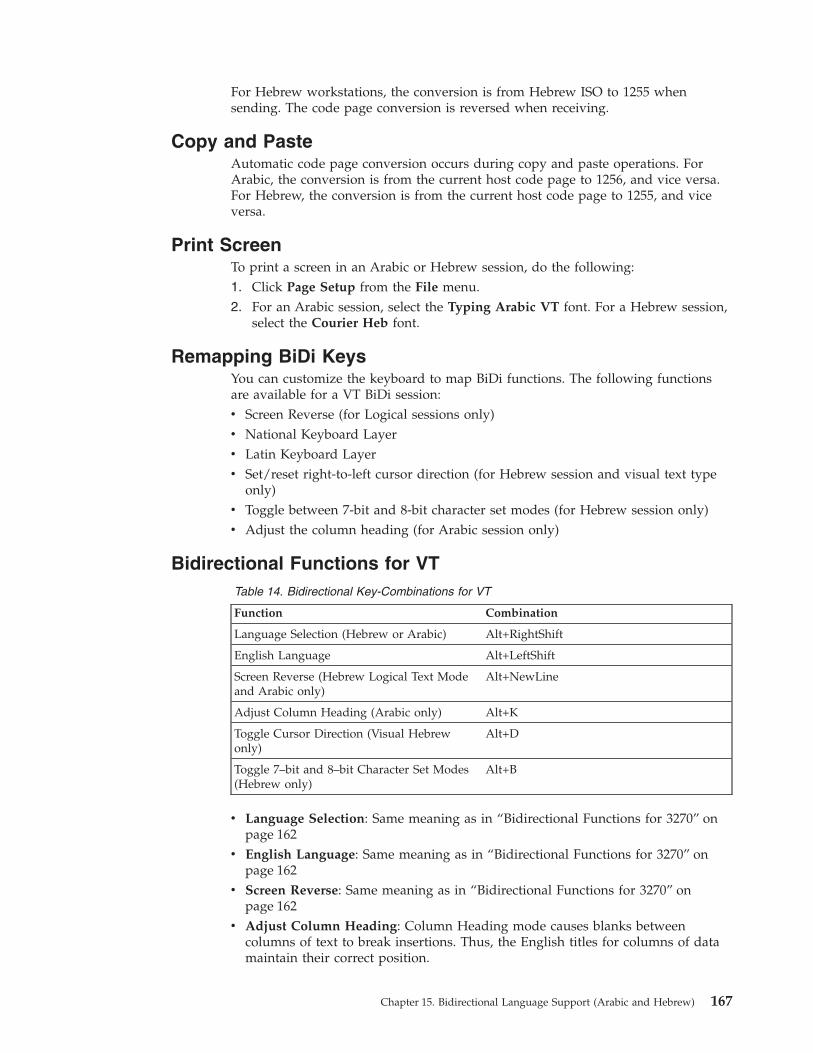
For Hebrew workstations, the conversion is from Hebrew ISO to 1255 whensending. The code page conversion is reversed when receiving.
Copy and PasteAutomatic code page conversion occurs during copy and paste operations. ForArabic, the conversion is from the current host code page to 1256, and vice versa.For Hebrew, the conversion is from the current host code page to 1255, and viceversa.
Print ScreenTo print a screen in an Arabic or Hebrew session, do the following:1. Click Page Setup from the File menu.2. For an Arabic session, select the Typing Arabic VT font. For a Hebrew session,
select the Courier Heb font.
Remapping BiDi KeysYou can customize the keyboard to map BiDi functions. The following functionsare available for a VT BiDi session:v Screen Reverse (for Logical sessions only)v National Keyboard Layerv Latin Keyboard Layerv Set/reset right-to-left cursor direction (for Hebrew session and visual text type
only)v Toggle between 7-bit and 8-bit character set modes (for Hebrew session only)v Adjust the column heading (for Arabic session only)
Bidirectional Functions for VTTable 14. Bidirectional Key-Combinations for VT
Function Combination
Language Selection (Hebrew or Arabic) Alt+RightShift
English Language Alt+LeftShift
Screen Reverse (Hebrew Logical Text Modeand Arabic only)
Alt+NewLine
Adjust Column Heading (Arabic only) Alt+K
Toggle Cursor Direction (Visual Hebrewonly)
Alt+D
Toggle 7–bit and 8–bit Character Set Modes(Hebrew only)
Alt+B
v Language Selection: Same meaning as in “Bidirectional Functions for 3270” onpage 162
v English Language: Same meaning as in “Bidirectional Functions for 3270” onpage 162
v Screen Reverse: Same meaning as in “Bidirectional Functions for 3270” onpage 162
v Adjust Column Heading: Column Heading mode causes blanks betweencolumns of text to break insertions. Thus, the English titles for columns of datamaintain their correct position.
Chapter 15. Bidirectional Language Support (Arabic and Hebrew) 167

v Toggle Cursor Direction: If current cursor direction is left-to-right, pressingAlt+D changes it to right-to-left, and back again. When the cursor direction is setto right-to-left, this does not affect cursor addressing , moving, inserting, anddeleting characters, erasing in line or erasing in display.The following functions are affected by the right-to-left cursor direction setting:– Backspace (the cursor moves one position to the right)– Carriage return (the cursor moves to the rightmost position on the current
line)– Line feed (the cursor moves to the rightmost position of the next line)– Typing in the auto wrap mode (current line is continued from rightmost
position of the next line)v Toggle 7–bit and 8–bit Character Set Modes: This function allows switching
between 7-bit and 8-bit character sets. If the current character set is ISO Hebrew(8-bit), pressing Alt+B changes the character set to Hebrew NRCS (7-bit).
Arabic Support for ASMO 449 7-bit Code PageThe following Control Sequences are supported for ASMO 449 7-bit code page.
Table 15. Control Sequences for Arabic VT Support
Control Sequence Description
Arabic Mode and State Controls
DECSABM v Arabization disabled
v BiDi with Text Controls
v BiDi without Text Controls
DDECSNL Start new Arabic/Latin language
DECVTCM v Invisible Text Controls
v Visible Text Controls
DECSAPV Numerals displayed in Arabic/Hindi,according to context
Arabic Imaging Controls
DECBDOCPD Set the direction of the screen (DocumentPresentation Direction)
Arabic Text Controls
SLR Start LTR direction
SRL Start RTL direction
SDD SDD start default direction
168 Personal Communications Administrator’s Guide and Reference

Chapter 16. Unicode Support
For Windows NT and 2000, Personal Communications Version 5.6 supportsUnicode for Hindi and 1390/1399 Japanese code pages.
For a description of the procedure for configuring Personal Communications Hindisupport, refer to Quick Beginnings. Installation information is described in theCD-ROM Guide to Installation.
1390/1399 Code PagesThe following features are supported in Unicode for 1390/1399 Japanese characterprocessing.v Print Screenv Record and play macrosv Data and file transferv Copy, Cut, and Pastev EHLLAPI. Refer to Emulator Programming for information about 1390/1399
transfer APIs.v Keyboard Customization
See the following list for more information about specific 1390/1399 support issues.
DBCS Translation TablePersonal Communications maps 1390/1399 code pages as follows:v 1390-->UCS2v UCS2-->1390v 1399-->UCS2v UCS2-->1399v 1399-->943v 943-->1390
Personal Communications loads a different translation table for display.
Personal Communications handles the Unicode printing both for GDImode and PDT mode.
Data and File TransferFile transfer uses the EBCDIC<-->UNICODE (or EBCDIC<-->ASCII )translation for Host to PC. The user can save as an ASCII file or as aUnicode file.
User Defined Area (UDA) SupportPersonal Communications handles EBCDIC<-->UNICODE (UDC), which isdifferent from EBCDIC <--> ASCII. The DBCS UDA mapping table editorhandles UNICODE<--> EBCDIC UDA.
© Copyright IBM Corp. 1989, 2002 169

Hindi SupportThe following features are supported in Unicode for Hindi.v Print Screenv Data transfer. File transfer is not supported.v Copy, Copy Append, Cut, and Paste. Copy Link is not supported.v EHLLAPI. Refer to Emulator Programming for information about Hindi data
transfer APIs.v Trace
See the following list for more information about specific Hindi support issues.
Code PageThe host code page for Hindi is 1137. The Unicode PC code page is 1200.Personal Communications uses a predefined translation table to map thesecode pages.
Record and Play MacrosHindi enablement is limited to macro scripts only. Customization of themacro file is disabled in Hindi sessions. VB scripts are not supported.
Fonts Only True Type Fonts are used for Hindi for display and printing. The TTFfile is enumerated by Personal Communications and is displayed in thePage Setup pull-down menu. This font file has to be selected for printingthe characters in Hindi. The Hindi font file is installed along with otherfont files.
KeyboardThe English keyboard layout is mapped to the Hindi layout. This isaccomplished by loading the two key mapping tables corresponding toHindi from the PCSKBD.DLL file. The first table maps the Windows virtualkey number to the IBM key number. The second key mapping table mapsthe IBM key number to the Unicode value of the corresponding character.
Keyboard CustomizationWhen a key is selected in the Keyboard Customization dialog, the editcontrol window displays the corresponding Hindi character. The user canchange the mapping by selecting a new character from the list box. If theuser attempts to directly edit the edit control window, the characters fromthe current input character set appear.
Copy/Move/Swap and Find keysThe function of these keys is similar to that of the existing SBCS languages.The only difference is that the Hindi characters are stored as Unicodecharacters instead of single-byte characters.
Switching from Hindi to EnglishHindi language support also includes toggling between Hindi and Englishusing the ALT+left Shift key.
OIA DisplayThe Operator Information Area displays functions differently for WindowsNT, and Windows 2000 and XP.
Windows NTWhen a user is working in the Hindi compose mode, HI isdisplayed in columns 36 and 37 of the OIA display; when workingin English compose mode, E is displayed. The user can togglebetween Hindi and English using ALT+left Shift key.
170 Personal Communications Administrator’s Guide and Reference

Windows 2000 and XPIn Windows 2000 and XP, HI is displayed in the OIA whenworking in Hindi mode. There is no display when the user shiftsfrom Hindi mode.
Chapter 16. Unicode Support 171

172 Personal Communications Administrator’s Guide and Reference

Part 5. Building a Printer Definition Table (PDT)
© Copyright IBM Corp. 1989, 2002 173

174 Personal Communications Administrator’s Guide and Reference
Chapter 17. Building a Printer Definition Table (PDT) forPC/3270
This chapter, in combination with Chapter 18, “Building a Printer Definition Table(PDT) for PC400” on page 185, explains how to customize a printer definition table(PDT file) for PC/3270. Chapter 18, “Building a Printer Definition Table (PDT) forPC400” on page 185 contains basic information about creating and changing PDTs;this chapter contains specific information about creating PC/3270 PDTs. PDTs forPC/3270 and PC400 differ only slightly; if you use a common PDT (used for bothPC/3270 and PC400), the additional statements for PC400 are ignored for PC/3270processing. Similarly, statements unique to PC/3270 are ignored for PC400processing.
ASCII_PASSTHRU? and EBCDIC_PASSTHRU?The ASCII_PASSTHRU? and EBCDIC_PASSTHRU? PDF statements are newoptions available for PC/3270. See “Transparent Print Capability” on page 189 fordetails.
Supplemental Explanation of PDF Statements for PC/3270The following PDF statements have functions that differ from those for PC400. Allstatements are listed in “Field Names of Printer Definition Files” on page 201.
MAXIMUM_PAGE_LENGTHPrinted lines per page. If you change this value, you must change thevalue in the SET_PAGE_LENGTH=SFL value statement (see “Sessionparameters” on page 187) to be the same.
MAXIMUM_PRINT_POSITIONPrinted characters per line.
COMPRESS_LINE_SPACING?(For LU 3 only) Whether blank or null lines are to be printed if allcharacters on that line are nulls.
FORM_FEED_ANY_POSITION?Whether a form feed is to be valid in any position. If NO, a form feed willbe valid only in the following positions:v First print-position of the bufferv After a valid new line operationv First print-position of a line
OVERRIDE_FORMATTED_PRINT?Whether nulls are to be printed as blanks.
INTERV_REQ_TIMERThis statement is ignored.
INTERV_TIMER_ON_PE_ONLY?This statement is ignored.
RESELECT_TIME_EXCPT_5204This statement is ignored.
ESC/P_LINE_FEED?If YES, the line feed (LF) function is emulated when the line feed
© Copyright IBM Corp. 1989, 2002 175

command is received. This is useful when you do not want a line feedaccompanied by a carriage return (CR) on a printer using the ESC/Pprinter language. If NO, the value defined in the LINE_FEED statement issent to the printer.
IGNORE_FORM_FEED_AT_FIRST_POS?If YES, the form feed (FF) function is ignored at the first position (for LU 2,LU 3, and non-SNA sessions) or at the beginning of the print job (for LU 1sessions). Using this option eliminates extra blank pages at the beginningof each print job.
FORM_FEED_TAKES_POSITION?If YES, the form feed (FF) function is effective if followed by data (LU 2,LU 3, and non-SNA sessions only).
KANJI_CODE?If YES, kanji codes (JIS or SHIFT_JIS) have been used. This value cannot bechanged.
ZENKAKU_SPACEThe size (adjustment unit) of a user-defined character and a HANKAKUcharacter. This value cannot be changed.
SBCS_FONT_LOADRegistration of a HANKAKU GAIJI. This value cannot be changed.
DBCS_FONT_LOADRegistration of a ZENKAKU GAIJI. This value cannot be changed.
SET_LOCAL_FONTSet a font set of user-defined characters. Remove it when user-definedcharacters are not loaded to a printer.
RESET_LOCAL_FONTReset a font set of user-defined characters. Remove it when user-definedcharacters are not loaded to a printer.
KANJI_ONSet kanji mode.
KANJI_OFFReset kanji mode.
ATTRIBUTE_GRID_LINESet to grid-line print. This value cannot be changed.
START_DOUBLE_WIDTH_CHARACTERSet a double-width character.
END_DOUBLE_WIDTH_CHARACTERReset a double-width character.
Notes:
1. When using IBM5577.PDF, change FORM_FEED=EJC to FORM_FEED in thefile when a continuous form job does not feed correctly.
2. When using ESC_P.PDF, DBCS (2-byte) characters are placed to the left of thecharacter box, not in the center. To place DBCS characters in the center of thecharacter box, change the IBM-supplied values in ESC_P.PDF:
P10 EQU 1B 50 1B 20 00 1C 53 00 0C 1C 54 00 00P12 EQU 1B 4D 1B 20 00 1C 53 00 06 1C 54 00 00P13 EQU 1B 67 1B 20 01 1C 53 00 03 1C 54 00 01P15 EQU 1B 67 1B 20 00 1C 53 00 00 1C 54 00 00
176 Personal Communications Administrator’s Guide and Reference
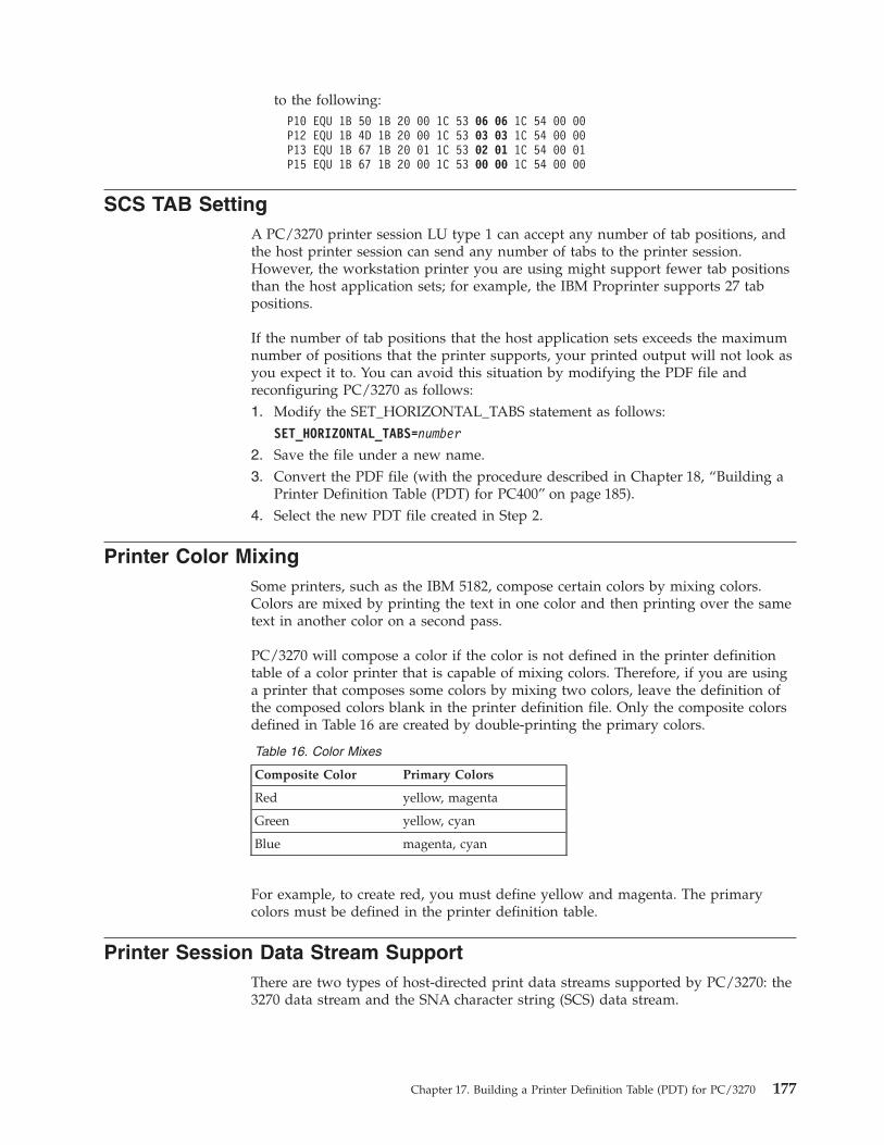
to the following:P10 EQU 1B 50 1B 20 00 1C 53 06 06 1C 54 00 00P12 EQU 1B 4D 1B 20 00 1C 53 03 03 1C 54 00 00P13 EQU 1B 67 1B 20 01 1C 53 02 01 1C 54 00 01P15 EQU 1B 67 1B 20 00 1C 53 00 00 1C 54 00 00
SCS TAB SettingA PC/3270 printer session LU type 1 can accept any number of tab positions, andthe host printer session can send any number of tabs to the printer session.However, the workstation printer you are using might support fewer tab positionsthan the host application sets; for example, the IBM Proprinter supports 27 tabpositions.
If the number of tab positions that the host application sets exceeds the maximumnumber of positions that the printer supports, your printed output will not look asyou expect it to. You can avoid this situation by modifying the PDF file andreconfiguring PC/3270 as follows:1. Modify the SET_HORIZONTAL_TABS statement as follows:
SET_HORIZONTAL_TABS=number
2. Save the file under a new name.3. Convert the PDF file (with the procedure described in Chapter 18, “Building a
Printer Definition Table (PDT) for PC400” on page 185).4. Select the new PDT file created in Step 2.
Printer Color MixingSome printers, such as the IBM 5182, compose certain colors by mixing colors.Colors are mixed by printing the text in one color and then printing over the sametext in another color on a second pass.
PC/3270 will compose a color if the color is not defined in the printer definitiontable of a color printer that is capable of mixing colors. Therefore, if you are usinga printer that composes some colors by mixing two colors, leave the definition ofthe composed colors blank in the printer definition file. Only the composite colorsdefined in Table 16 are created by double-printing the primary colors.
Table 16. Color Mixes
Composite Color Primary Colors
Red yellow, magenta
Green yellow, cyan
Blue magenta, cyan
For example, to create red, you must define yellow and magenta. The primarycolors must be defined in the printer definition table.
Printer Session Data Stream SupportThere are two types of host-directed print data streams supported by PC/3270: the3270 data stream and the SNA character string (SCS) data stream.
Chapter 17. Building a Printer Definition Table (PDT) for PC/3270 177

3270 Data StreamThe 3270 data stream is a buffer-oriented data stream. The print data is formattedas if it were going to be displayed on a screen. The host system sends commandsto format the presentation space. These commands can change the presentationspace in any location at any time. Once the host system completes formatting thepresentation space, it issues a START PRINT command and the presentation spaceis printed as accurately as the printer hardware allows. The 3270 data stream canbe sent to PC/3270 workstations over an SNA LU 3 session or a non-SNA DFTprinter session.
Table 17 lists the commands that can be sent in the 3270 data stream.
Table 17. 3270 Data Stream Commands
Command Meaning
W Write
EW Erase/Write
EWA Erase/Write Alternate
RB Read Buffer
RM Read Modified
RMA Read Modified All
EAU Erase All Unprotected
WSF Write Structured Field
The RB, RM, and RMA commands cannot be used with an SNA attachment.
Table 18 lists the orders that can be sent in the 3270 data stream.
Table 18. 3270 Data Stream Orders
Order Meaning
SBA Start Buffer Address
SF Start Field
IC Insert Cursor
PT Program Tab
RA Repeat to Address
EUA Erase Unprotected to Address
SFE Start Field Extended
SA Set Attribute
MF Modify Field
The last three orders in the preceding table manage the color, extendedhighlighting, and programmed symbols attributes for fields and individualcharacters. The programmed symbols attribute is not supported by PC/3270.
In addition to the commands and orders in the two preceding tables, there arespecial printer formatting control codes that can be included in the 3270 datastream.
178 Personal Communications Administrator’s Guide and Reference

The following table lists the control codes that can be sent in the 3270 data stream.
Table 19. 3270 Data Stream Format Control Codes
Code Description
NL New Line control code moves the print position to the left margin anddown one line.
CR Carriage Return control code moves the print position to the leftmargin.
EM End of Message control code ends the print operation.
FF Form Feed control code moves the print position to the left margin atthe top of the next page.
Note: NL, CR, and EM are valid only if a line-length format specified by the WCCis not used. The FF code is valid in any buffer position.
PC/3270 printer support interprets each 3270 attribute and printer control codeand translates them into a sequence of one or more workstation printer controlcodes. For more information about the 3270 data stream, refer to IBM 3270Information Display Data Stream Programmer’s Reference.
SCS Data StreamThe SCS data stream is a sequential data stream that is oriented toward lineprinters. The characters are translated according to the host system code page andprinted according to the attributes and formatting specified by the controlcommands. The way in which SCS characters are printed depends only on thecontrol codes that precede them. Therefore, it is not necessary to buffer thecharacters before they are printed. The SCS data stream flows across the SNA LU 1session only.
The valid SCS control codes supported by PC/3270 are listed in Table 20.
Table 20. Supported SCS Control Codes
Code Value Command
NL X'15' New Line
LF X'25' Linefeed (Index)
CR X'0D' Carriage Return
FF X'0C' Form Feed
BS X'16' Backspace
BEL X'2F' Bell Function
IRS X'1E'Interchange-RecordSeparator
SA X'28' Set Attribute
TRN X'35' Transparent
NUL X'00' Null
HT X'05' Horizontal Tab
VT X'0B' Vertical Tab
SHF X'2B C1' Set Horizontal Format
SVF X'2B C2' Set Vertical Format
Chapter 17. Building a Printer Definition Table (PDT) for PC/3270 179
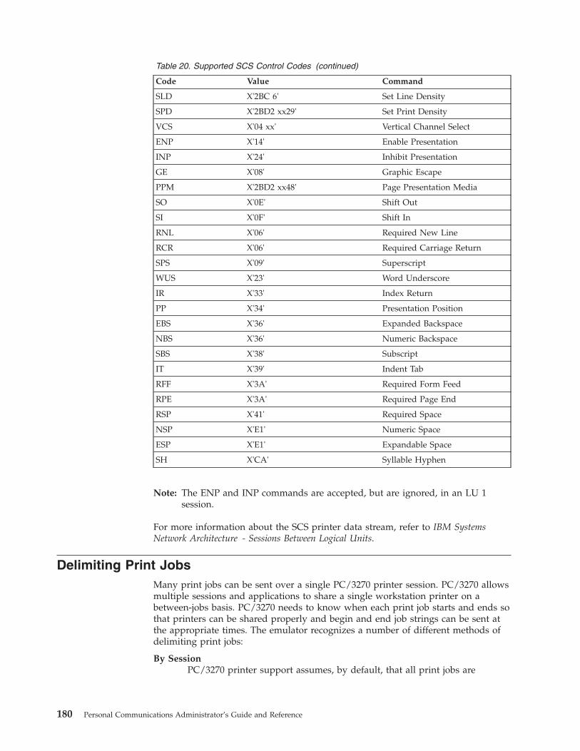
Table 20. Supported SCS Control Codes (continued)
Code Value Command
SLD X'2BC 6' Set Line Density
SPD X'2BD2 xx29' Set Print Density
VCS X'04 xx' Vertical Channel Select
ENP X'14' Enable Presentation
INP X'24' Inhibit Presentation
GE X'08' Graphic Escape
PPM X'2BD2 xx48' Page Presentation Media
SO X'0E' Shift Out
SI X'0F' Shift In
RNL X'06' Required New Line
RCR X'06' Required Carriage Return
SPS X'09' Superscript
WUS X'23' Word Underscore
IR X'33' Index Return
PP X'34' Presentation Position
EBS X'36' Expanded Backspace
NBS X'36' Numeric Backspace
SBS X'38' Subscript
IT X'39' Indent Tab
RFF X'3A' Required Form Feed
RPE X'3A' Required Page End
RSP X'41' Required Space
NSP X'E1' Numeric Space
ESP X'E1' Expandable Space
SH X'CA' Syllable Hyphen
Note: The ENP and INP commands are accepted, but are ignored, in an LU 1session.
For more information about the SCS printer data stream, refer to IBM SystemsNetwork Architecture - Sessions Between Logical Units.
Delimiting Print JobsMany print jobs can be sent over a single PC/3270 printer session. PC/3270 allowsmultiple sessions and applications to share a single workstation printer on abetween-jobs basis. PC/3270 needs to know when each print job starts and ends sothat printers can be shared properly and begin and end job strings can be sent atthe appropriate times. The emulator recognizes a number of different methods ofdelimiting print jobs:
By SessionPC/3270 printer support assumes, by default, that all print jobs are
180 Personal Communications Administrator’s Guide and Reference

delimited by sessions. That is, in the absence of all other indicators,PC/3270 assumes that a print job begins when a printer session is startedand ends when it is reset.
Time-Out IntervalOn non-SNA DFT sessions, print jobs can be delimited by a user-specifiedtimeout interval. A print job on a non-SNA DFT printer session beginswhen the first host-outbound data for that job is received, and ends whenno host-outbound data is received for a period of time exceeding theuser-specified non-SNA DFT timeout interval. For PC/3270, this interval isspecified during configuration.
By BracketsOn an SNA session with an LU 1 or LU 3 host application, PC/3270 canuse bracket indicators to delimit print jobs. The emulator opens the printerwhen it receives the begin bracket, then it processes and prints data. Theemulator closes the printer after it receives an end bracket.
When the emulator receives another begin bracket, it again opens a printerand begins processing a print job.
Structured FieldsThe host can use structured fields to indicate to the device that a new fileis beginning or that the current file is completed. PC/3270 delimits printjobs with Begin of File and End of File structured fields (SF) to performhost-directed printing. Structured fields are described in “StructuredFields”.
Structured FieldsThe host uses Begin of File and End of File structured fields to indicate to a devicethat a file is beginning or ending.
Begin/End of File Query ReplyThe Begin/End of File query reply indicates that a device supports Begin of Fileand End of File to delineate print jobs. The PC/3270 sends a query reply, as shownin Table 21, to the host in response to a Read Partition General query.
Table 21. Begin/End of File Query Reply Format
Byte Contents Description
0–1 X'0005' The length of this structure
2 X'81' Query reply
3 QCODE X'9F' Begin/End of File
4 FLAGS Reserved; must be set to 0’s
Begin/End of File Structured FieldsBegin/End of File structured fields are accepted on either LU 1 or LU 3 sessions.Table 22 shows the format of the Begin/End of File structured fields.
Table 22. Begin/End of File Structured Field Format
Byte Bit Contents Description
0–1 X'0007' The length of this structure
2–3 X'0F85' Begin/End of File
Chapter 17. Building a Printer Definition Table (PDT) for PC/3270 181
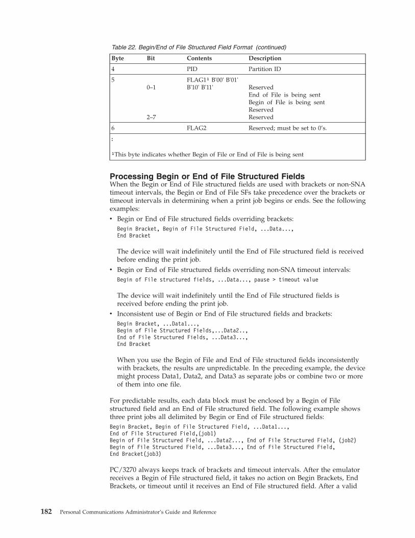
Table 22. Begin/End of File Structured Field Format (continued)
Byte Bit Contents Description
4 PID Partition ID
50–1
2–7
FLAG1¹ B'00' B'01'B'10' B'11' Reserved
End of File is being sentBegin of File is being sentReservedReserved
6 FLAG2 Reserved; must be set to 0’s.
:
¹This byte indicates whether Begin of File or End of File is being sent
Processing Begin or End of File Structured FieldsWhen the Begin or End of File structured fields are used with brackets or non-SNAtimeout intervals, the Begin or End of File SFs take precedence over the brackets ortimeout intervals in determining when a print job begins or ends. See the followingexamples:v Begin or End of File structured fields overriding brackets:
Begin Bracket, Begin of File Structured Field, ...Data...,End Bracket
The device will wait indefinitely until the End of File structured field is receivedbefore ending the print job.
v Begin or End of File structured fields overriding non-SNA timeout intervals:Begin of File structured fields, ...Data..., pause > timeout value
The device will wait indefinitely until the End of File structured fields isreceived before ending the print job.
v Inconsistent use of Begin or End of File structured fields and brackets:Begin Bracket, ...Data1...,Begin of File Structured Fields,...Data2..,End of File Structured Fields, ...Data3...,End Bracket
When you use the Begin of File and End of File structured fields inconsistentlywith brackets, the results are unpredictable. In the preceding example, the devicemight process Data1, Data2, and Data3 as separate jobs or combine two or moreof them into one file.
For predictable results, each data block must be enclosed by a Begin of Filestructured field and an End of File structured field. The following example showsthree print jobs all delimited by Begin or End of File structured fields:Begin Bracket, Begin of File Structured Field, ...Data1...,End of File Structured Field,(job1)Begin of File Structured Field, ...Data2..., End of File Structured Field, (job2)Begin of File Structured Field, ...Data3..., End of File Structured Field,End Bracket(job3)
PC/3270 always keeps track of brackets and timeout intervals. After the emulatorreceives a Begin of File structured field, it takes no action on Begin Brackets, EndBrackets, or timeout until it receives an End of File structured field. After a valid
182 Personal Communications Administrator’s Guide and Reference

End of File SF is processed, the emulator defaults to delimiting jobs by brackets ortimeout intervals until it receives the next Begin of File structured field.
Begin or End of File Structured Field Error ConditionsPC/3270 does not accept transmission of data belonging to two separate print jobsin the same chain. To be accepted by the emulator, Begin of File structured fieldsmust be the first structured field of a chain and End of File structured fields mustbe the last structured field of a chain.
PC/3270 rejects transmission in the following instances:v The emulator receives an End of File structured field without first receiving a
Begin of File structured field.v The emulator receives a second Begin of File structured field without receiving
an intervening End of File structured field.v The emulator receives a Begin of File structured field that is not the first
structured field following a write structured field command (LU 2, LU 3, andnon-SNA sessions) or a Function Management Header 1 (LU 1 sessions).
v The emulator receives an End of File structured field that is not the laststructured field following a write structured field command (LU 2, LU 3, andnon-SNA sessions) or a Function Management Header 1 (LU 1 sessions).
Processing SCS Data StreamsWhen processing an SCS data stream, PC/3270 treats Begin or End of Filestructured fields as follows:v A Begin of File structured field indicates that all SCS data in the same
transmission until an End of File structured field is received is part of a newprint job.
v An End of File structured field indicates that any SCS data received in the samechain as the End of File structured field is the last data of the current print job.
Processing 3270 Data StreamsWhen processing a 3270 data stream, PC/3270 treats Begin or End of Filestructured fields as follows:v A Begin of File structured field indicates that the next presentation space print
(initiated by a write type command with the start print bit turned on in thewrite control character) is the first in a print job.
v An End of File structured field indicates that the last presentation space printwas the last of the current print job. The emulator immediately sends aterminate string to the printer to close the printer session.
If PC/3270 receives a Begin of File structured field and an End of File structuredfield without at least one presentation space separating them, it ignores thestructured fields.
Chapter 17. Building a Printer Definition Table (PDT) for PC/3270 183

184 Personal Communications Administrator’s Guide and Reference
Chapter 18. Building a Printer Definition Table (PDT) forPC400
This chapter explains how to create and change the printer definition table (PDTfile) used for PC400. Chapter 17, “Building a Printer Definition Table (PDT) forPC/3270” on page 175 contains specific information about creating PC/3270 PDTs.PDTs for PC/3270 and PC400 differ only slightly; if you use a common PDT (usedfor both PC/3270 and PC400), the additional statements for PC400 are ignored forPC/3270 processing. Similarly, statements unique to PC/3270 are ignored forPC400 processing.
The PDT file is created by converting the printer definition file (PDF file). The PDFand PDT define the transmission of characters and control codes to the printer andthe format of printer output. To change an existing PDF (the recommendedmethod) or create a new one, use a text editor that can produce or update anASCII file.
Using the Printer Definition Table (PDT) FileTo use the PDT file:1. Select File from the menu bar of the workstation window.2. Select Printer Setup from the File menu.
The Printer Setup window appears.3. Select the Use PDT file check box and Select PDT.
The Select PDT file window appears.
To build the PDT file (required only if the PDF has been changed or created):1. Select Convert PDF. Select the PDF file to be converted from the list in the
Convert PDF to PDT window; then select Convert. The PDF File Converterwindow appears. After the file has been converted, click on Close, then clickClose in the Convert PDF to PDT window.
2. Click OK in the Select PDT file window.3. Click OK on the Printer Setup window.
After printer setup is complete, the Printer Setup window is closed.
Printer Definition File (PDF File) FormatA PDF contains 3 main sections:v Macro definitionsv Formatting controlsv Character definitions using EBCDIC_xx keywords
Macro DefinitionsThis section of a PDF contains user-defined macros. A macro is a single mnemonicthat stands for a control code or a sequence of control codes. A mnemonicsimplifies defining control sequences for PC printers and makes it easier to readthe information in the PDF.
© Copyright IBM Corp. 1989, 2002 185
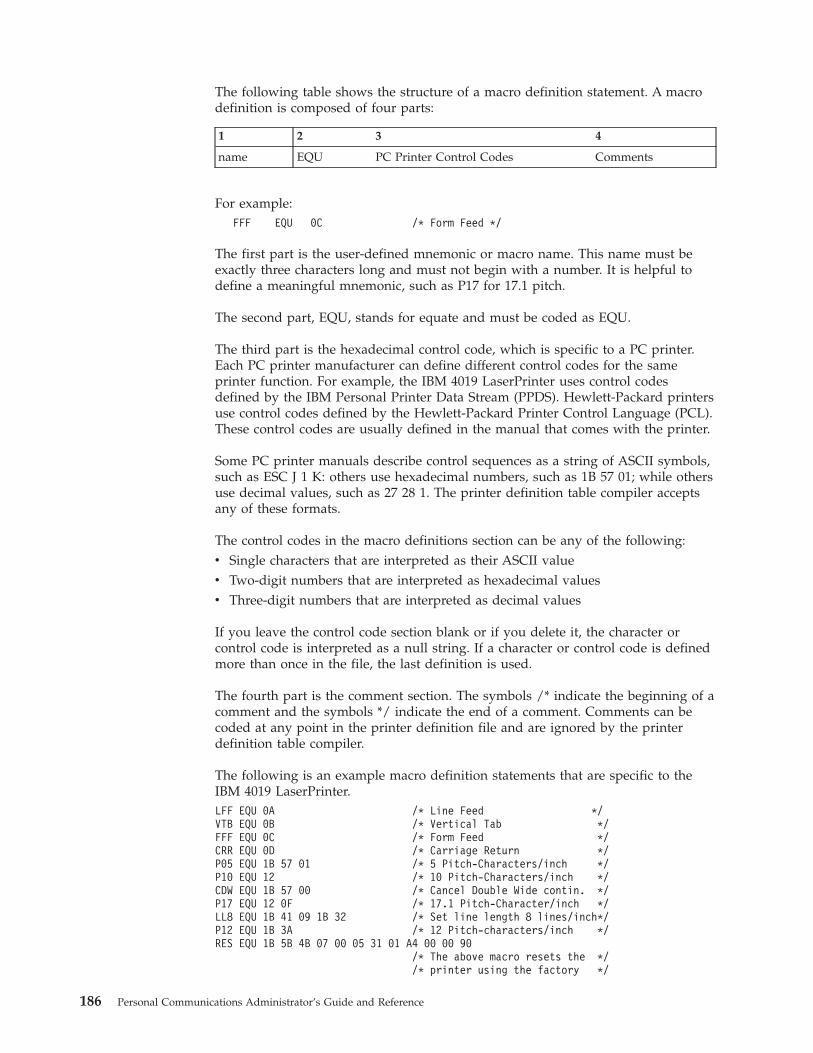
The following table shows the structure of a macro definition statement. A macrodefinition is composed of four parts:
1 2 3 4
name EQU PC Printer Control Codes Comments
For example:FFF EQU 0C /* Form Feed */
The first part is the user-defined mnemonic or macro name. This name must beexactly three characters long and must not begin with a number. It is helpful todefine a meaningful mnemonic, such as P17 for 17.1 pitch.
The second part, EQU, stands for equate and must be coded as EQU.
The third part is the hexadecimal control code, which is specific to a PC printer.Each PC printer manufacturer can define different control codes for the sameprinter function. For example, the IBM 4019 LaserPrinter uses control codesdefined by the IBM Personal Printer Data Stream (PPDS). Hewlett-Packard printersuse control codes defined by the Hewlett-Packard Printer Control Language (PCL).These control codes are usually defined in the manual that comes with the printer.
Some PC printer manuals describe control sequences as a string of ASCII symbols,such as ESC J 1 K: others use hexadecimal numbers, such as 1B 57 01; while othersuse decimal values, such as 27 28 1. The printer definition table compiler acceptsany of these formats.
The control codes in the macro definitions section can be any of the following:v Single characters that are interpreted as their ASCII valuev Two-digit numbers that are interpreted as hexadecimal valuesv Three-digit numbers that are interpreted as decimal values
If you leave the control code section blank or if you delete it, the character orcontrol code is interpreted as a null string. If a character or control code is definedmore than once in the file, the last definition is used.
The fourth part is the comment section. The symbols /* indicate the beginning of acomment and the symbols */ indicate the end of a comment. Comments can becoded at any point in the printer definition file and are ignored by the printerdefinition table compiler.
The following is an example macro definition statements that are specific to theIBM 4019 LaserPrinter.LFF EQU 0A /* Line Feed */VTB EQU 0B /* Vertical Tab */FFF EQU 0C /* Form Feed */CRR EQU 0D /* Carriage Return */P05 EQU 1B 57 01 /* 5 Pitch-Characters/inch */P10 EQU 12 /* 10 Pitch-Characters/inch */CDW EQU 1B 57 00 /* Cancel Double Wide contin. */P17 EQU 12 0F /* 17.1 Pitch-Character/inch */LL8 EQU 1B 41 09 1B 32 /* Set line length 8 lines/inch*/P12 EQU 1B 3A /* 12 Pitch-characters/inch */RES EQU 1B 5B 4B 07 00 05 31 01 A4 00 00 90
/* The above macro resets the *//* printer using the factory */
186 Personal Communications Administrator’s Guide and Reference
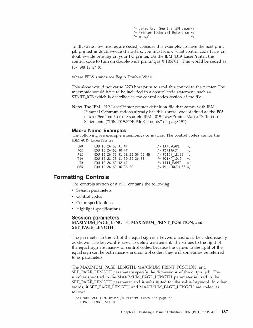
/* defaults. See the IBM Laser*//* Printer Technical Reference *//* manual. */
To illustrate how macros are coded, consider this example. To have the host printjob printed in double-wide characters, you must know what control code turns ondouble-wide printing on your PC printer. On the IBM 4019 LaserPrinter, thecontrol code to turn on double-wide printing is X’1B5701’. This would be coded as:BDW EQU 1B 57 01
where BDW stands for Begin Double Wide.
This alone would not cause 3270 host print to send this control to the printer. Themnemonic would have to be included in a control code statement, such asSTART_JOB which is described in the control codes section of the file.
Note: The IBM 4019 LaserPrinter printer definition file that comes with IBMPersonal Communications already has this control code defined as the P05macro. See line 9 of the sample IBM 4019 LaserPrinter Macro DefinitionStatements (“IBM4019.PDF File Contents” on page 191).
Macro Name ExamplesThe following are example mnemonics or macros. The control codes are for theIBM 4019 LaserPrinter:
LND EQU 1B 26 6C 31 4F /* LANDSCAPE */POR EQU 1B 26 6C 30 4F /* PORTRAIT */P12 EQU 1B 28 73 31 32 2E 30 30 48 /* PITCH_12.00 */T10 EQU 1B 28 73 31 30 2E 30 56 /* POINT_10.0 */LTR EQU 1B 26 6C 32 41 /* LETT_PAPER */G66 EQU 1B 26 6C 36 36 50 /* PG_LENGTH_66 */
Formatting ControlsThe controls section of a PDF contains the following:v Session parametersv Control codesv Color specificationsv Highlight specifications
Session parametersMAXIMUM_PAGE_LENGTH, MAXIMUM_PRINT_POSITION, andSET_PAGE_LENGTH
The parameter to the left of the equal sign is a keyword and must be coded exactlyas shown. The keyword is used to define a statement. The values to the right ofthe equal sign are macros or control codes. Because the values to the right of theequal sign can be both macros and control codes, they will sometimes be referredto as parameters.
The MAXIMUM_PAGE_LENGTH, MAXIMUM_PRINT_POSITION, andSET_PAGE_LENGTH parameters specify the dimensions of the output job. Thenumber specified in the MAXIMUM_PAGE_LENGTH parameter is used in theSET_PAGE_LENGTH parameter and is substituted for the value keyword. In otherwords, if SET_PAGE_LENGTH and MAXIMUM_PAGE_LENGTH are coded asfollows:MAXIMUM_PAGE_LENGTH=066 /* Printed lines per page */SET_PAGE_LENGTH=SFL 066
Chapter 18. Building a Printer Definition Table (PDT) for PC400 187
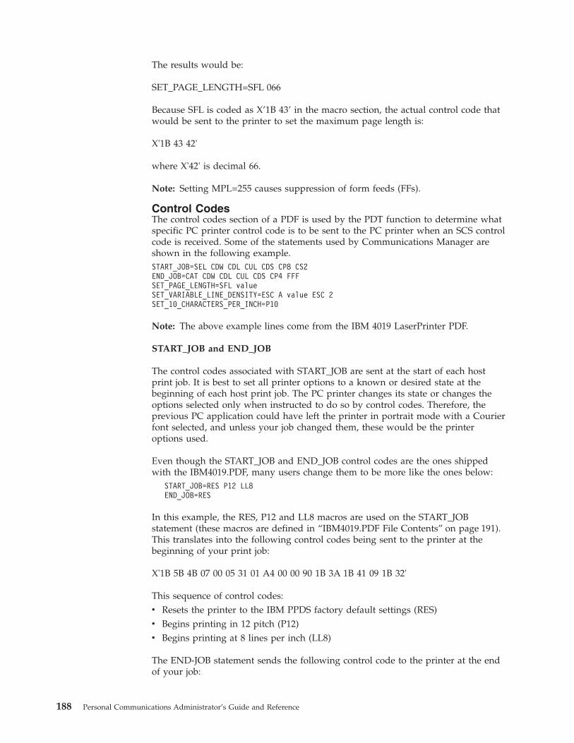
The results would be:
SET_PAGE_LENGTH=SFL 066
Because SFL is coded as X’1B 43’ in the macro section, the actual control code thatwould be sent to the printer to set the maximum page length is:
X'1B 43 42'
where X'42' is decimal 66.
Note: Setting MPL=255 causes suppression of form feeds (FFs).
Control CodesThe control codes section of a PDF is used by the PDT function to determine whatspecific PC printer control code is to be sent to the PC printer when an SCS controlcode is received. Some of the statements used by Communications Manager areshown in the following example.START_JOB=SEL CDW CDL CUL CDS CP8 CS2END_JOB=CAT CDW CDL CUL CDS CP4 FFFSET_PAGE_LENGTH=SFL valueSET_VARIABLE_LINE_DENSITY=ESC A value ESC 2SET_10_CHARACTERS_PER_INCH=P10
Note: The above example lines come from the IBM 4019 LaserPrinter PDF.
START_JOB and END_JOB
The control codes associated with START_JOB are sent at the start of each hostprint job. It is best to set all printer options to a known or desired state at thebeginning of each host print job. The PC printer changes its state or changes theoptions selected only when instructed to do so by control codes. Therefore, theprevious PC application could have left the printer in portrait mode with a Courierfont selected, and unless your job changed them, these would be the printeroptions used.
Even though the START_JOB and END_JOB control codes are the ones shippedwith the IBM4019.PDF, many users change them to be more like the ones below:
START_JOB=RES P12 LL8END_JOB=RES
In this example, the RES, P12 and LL8 macros are used on the START_JOBstatement (these macros are defined in “IBM4019.PDF File Contents” on page 191).This translates into the following control codes being sent to the printer at thebeginning of your print job:
X'1B 5B 4B 07 00 05 31 01 A4 00 00 90 1B 3A 1B 41 09 1B 32'
This sequence of control codes:v Resets the printer to the IBM PPDS factory default settings (RES)v Begins printing in 12 pitch (P12)v Begins printing at 8 lines per inch (LL8)
The END-JOB statement sends the following control code to the printer at the endof your job:
188 Personal Communications Administrator’s Guide and Reference

X'1B 5B 4B 07 00 05 31 01 A4 00 00 90'
This control code resets the printer to IBM PPDS factory default settings (RES).
SET_VARIABLE_LINE_DENSITY
The SET_VARIABLE_LINE_DENSITY statement is used in combination with thepanel where you can select the number of lines per inch (LPI), which can be either6 or 8.
The PDT process uses whatever is selected in the lines per inch field, andsubstitutes this number for the value keyword in theSET_VARIABLE_LINE_DENSITY parameter. In other words, if lines per inch is setto 8, the SET_VARIABLE_LINE_DENSITY parameter isSET_VARIABLE_LINE_DENSITY=ESC A 09 ESC 2
where the 09 comes from 72/8. The number of typographic points in 1 inch is 42;thus a value of 12 points would indicate six lines to an inch.
The control code that is sent to the printer to set the line density is:X’1B 41 09 1B 32’SET_10_CHARACTERS_PER_INCH
On most printers, the default pitch is 10 characters per inch. In most PDTs,Personal Communications uses this same convention and sends the control codefound on the SET_10_CHARACTERS_PER_INCH statement. This is usually codedin the PDF as:SET_10_CHARACTERS_PER_INCH=P10
where P10 is coded in the macro definition section as:P10 EQU 12
Transparent Print Capability
ASCII_PASSTHRU? Keyword SupportIf you add the following line to your PDF, Personal Communications will sendhost data without any translation:
ASCII_PASSTHRU? = YES
This option is for special host applications that generate PC printer control codesdirectly.
Even if ASCII_PASSTHRU? is set, control codes defined START_JOB and END_JOBare sent to the printer at the start and the end of a print job respectively. Toremove those commands, you need to rebuild the PDT file after removing the PDFkeyword definitions for START_JOB and END_JOB.
If ASCII_PASSTHRU? is set, all character definition lines, for example, EBCDIC_xx,are ignored.
If both ASCII_PASSTHRU? and EBCDIC_PASSTHRU? are set, ASCII_PASSTHRU?has priority.
Chapter 18. Building a Printer Definition Table (PDT) for PC400 189
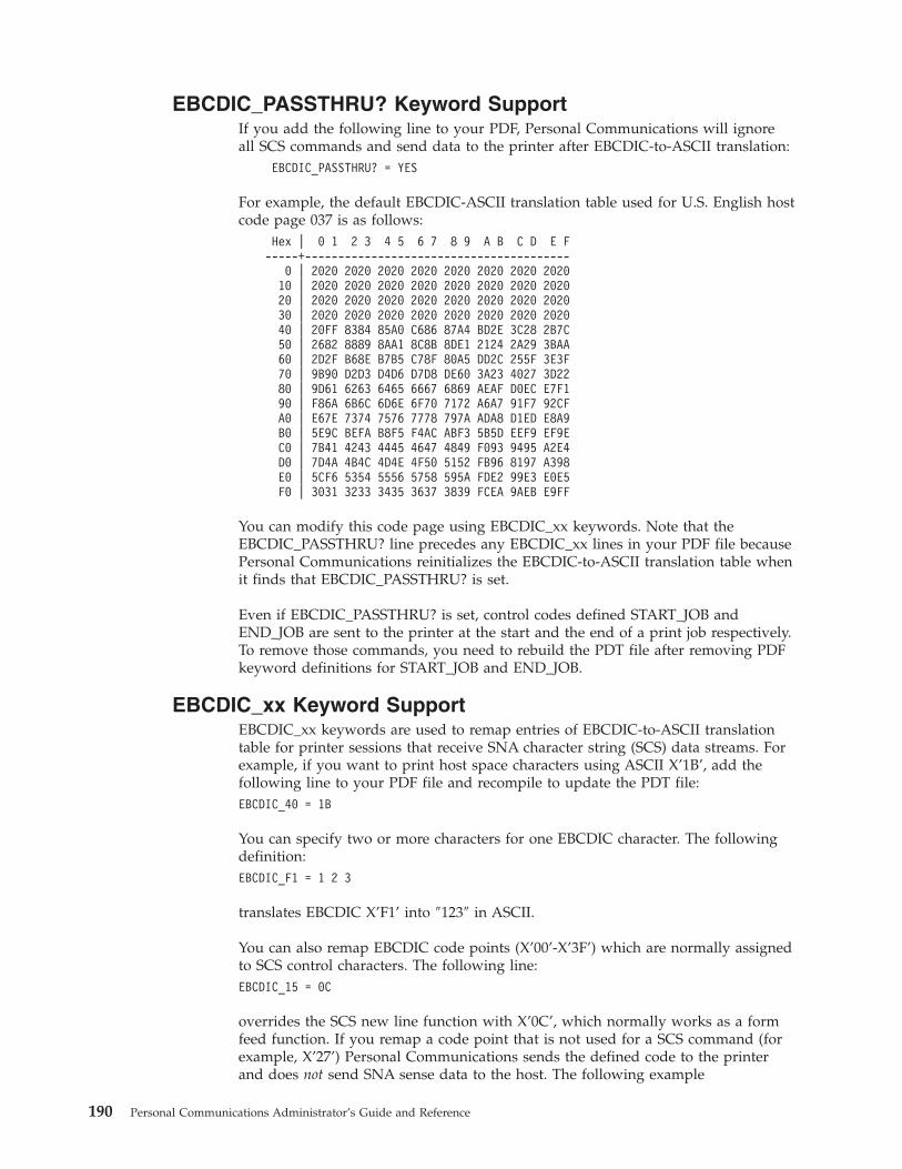
EBCDIC_PASSTHRU? Keyword SupportIf you add the following line to your PDF, Personal Communications will ignoreall SCS commands and send data to the printer after EBCDIC-to-ASCII translation:
EBCDIC_PASSTHRU? = YES
For example, the default EBCDIC-ASCII translation table used for U.S. English hostcode page 037 is as follows:
Hex | 0 1 2 3 4 5 6 7 8 9 A B C D E F-----+----------------------------------------
0 | 2020 2020 2020 2020 2020 2020 2020 202010 | 2020 2020 2020 2020 2020 2020 2020 202020 | 2020 2020 2020 2020 2020 2020 2020 202030 | 2020 2020 2020 2020 2020 2020 2020 202040 | 20FF 8384 85A0 C686 87A4 BD2E 3C28 2B7C50 | 2682 8889 8AA1 8C8B 8DE1 2124 2A29 3BAA60 | 2D2F B68E B7B5 C78F 80A5 DD2C 255F 3E3F70 | 9B90 D2D3 D4D6 D7D8 DE60 3A23 4027 3D2280 | 9D61 6263 6465 6667 6869 AEAF D0EC E7F190 | F86A 6B6C 6D6E 6F70 7172 A6A7 91F7 92CFA0 | E67E 7374 7576 7778 797A ADA8 D1ED E8A9B0 | 5E9C BEFA B8F5 F4AC ABF3 5B5D EEF9 EF9EC0 | 7B41 4243 4445 4647 4849 F093 9495 A2E4D0 | 7D4A 4B4C 4D4E 4F50 5152 FB96 8197 A398E0 | 5CF6 5354 5556 5758 595A FDE2 99E3 E0E5F0 | 3031 3233 3435 3637 3839 FCEA 9AEB E9FF
You can modify this code page using EBCDIC_xx keywords. Note that theEBCDIC_PASSTHRU? line precedes any EBCDIC_xx lines in your PDF file becausePersonal Communications reinitializes the EBCDIC-to-ASCII translation table whenit finds that EBCDIC_PASSTHRU? is set.
Even if EBCDIC_PASSTHRU? is set, control codes defined START_JOB andEND_JOB are sent to the printer at the start and the end of a print job respectively.To remove those commands, you need to rebuild the PDT file after removing PDFkeyword definitions for START_JOB and END_JOB.
EBCDIC_xx Keyword SupportEBCDIC_xx keywords are used to remap entries of EBCDIC-to-ASCII translationtable for printer sessions that receive SNA character string (SCS) data streams. Forexample, if you want to print host space characters using ASCII X’1B’, add thefollowing line to your PDF file and recompile to update the PDT file:EBCDIC_40 = 1B
You can specify two or more characters for one EBCDIC character. The followingdefinition:EBCDIC_F1 = 1 2 3
translates EBCDIC X’F1’ into ″123″ in ASCII.
You can also remap EBCDIC code points (X’00’-X’3F’) which are normally assignedto SCS control characters. The following line:EBCDIC_15 = 0C
overrides the SCS new line function with X’0C’, which normally works as a formfeed function. If you remap a code point that is not used for a SCS command (forexample, X’27’) Personal Communications sends the defined code to the printerand does not send SNA sense data to the host. The following example
190 Personal Communications Administrator’s Guide and Reference
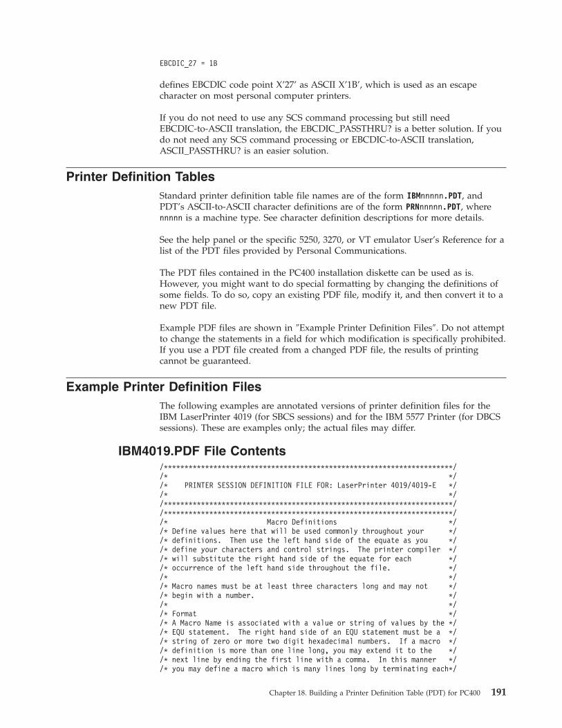
EBCDIC_27 = 1B
defines EBCDIC code point X’27’ as ASCII X’1B’, which is used as an escapecharacter on most personal computer printers.
If you do not need to use any SCS command processing but still needEBCDIC-to-ASCII translation, the EBCDIC_PASSTHRU? is a better solution. If youdo not need any SCS command processing or EBCDIC-to-ASCII translation,ASCII_PASSTHRU? is an easier solution.
Printer Definition TablesStandard printer definition table file names are of the form IBMnnnnn.PDT, andPDT’s ASCII-to-ASCII character definitions are of the form PRNnnnnn.PDT, wherennnnn is a machine type. See character definition descriptions for more details.
See the help panel or the specific 5250, 3270, or VT emulator User’s Reference for alist of the PDT files provided by Personal Communications.
The PDT files contained in the PC400 installation diskette can be used as is.However, you might want to do special formatting by changing the definitions ofsome fields. To do so, copy an existing PDF file, modify it, and then convert it to anew PDT file.
Example PDF files are shown in ″Example Printer Definition Files″. Do not attemptto change the statements in a field for which modification is specifically prohibited.If you use a PDT file created from a changed PDF file, the results of printingcannot be guaranteed.
Example Printer Definition FilesThe following examples are annotated versions of printer definition files for theIBM LaserPrinter 4019 (for SBCS sessions) and for the IBM 5577 Printer (for DBCSsessions). These are examples only; the actual files may differ.
IBM4019.PDF File Contents/**********************************************************************//* *//* PRINTER SESSION DEFINITION FILE FOR: LaserPrinter 4019/4019-E *//* *//**********************************************************************//**********************************************************************//* Macro Definitions *//* Define values here that will be used commonly throughout your *//* definitions. Then use the left hand side of the equate as you *//* define your characters and control strings. The printer compiler *//* will substitute the right hand side of the equate for each *//* occurrence of the left hand side throughout the file. *//* *//* Macro names must be at least three characters long and may not *//* begin with a number. *//* *//* Format *//* A Macro Name is associated with a value or string of values by the *//* EQU statement. The right hand side of an EQU statement must be a *//* string of zero or more two digit hexadecimal numbers. If a macro *//* definition is more than one line long, you may extend it to the *//* next line by ending the first line with a comma. In this manner *//* you may define a macro which is many lines long by terminating each*/
Chapter 18. Building a Printer Definition Table (PDT) for PC400 191

/* line except the last with a comma. No macro names are allowed on *//* right hand side. *//**********************************************************************/BEGIN_MACROS/* The following values are standard for most printers. Check your *//* printer manual to verify that these are correct for your printer */NUL EQU 00 /* Nul character */BEL EQU 07 /* Beeper */BAK EQU 08 /* Back Space */TAB EQU 09 /* Tab */LFF EQU 0A /* Line Feed */VTB EQU 0B /* Vertical Tab */FFF EQU 0C /* Form Feed */CRR EQU 0D /* Carriage Return */P05 EQU 1B 57 01 /* 5 Pitch-Characters/inch */
/* Same as Double Wide */SEL EQU 11 /* Select Printer */P10 EQU 12 /* 10 Pitch-Characters/inch */CDW EQU 1B 57 00 /* Cancel Double Wide contin. */CDL EQU 14 /* Cancel Double Wide line */ESC EQU 1B /* Escape */CAN EQU 18 /* Cancel Data */SPA EQU 20 /* Space */P17 EQU 12 0F /* 17.1 Pitch-Characters/inch */CS2 EQU 1B 36 /* Select Character Set 2 */CS1 EQU 1B 37 /* Select Character Set 1 */P12 EQU 1B 3A /* 12 Pitch-characters/inch */SVT EQU 1B 42 /* Set Vertical Tabs */SFL EQU 1B 43 00 /* Set Form Length */SHT EQU 1B 44 /* Set Horizontal Tabs */SDS EQU 1B 47 /* Start Double Strike */CDS EQU 1B 48 /* Cancel Double Strike */SSP EQU 1B 4E /* Set skip perforation */CSP EQU 1B 4F /* Cancel skip perforation */CAT EQU 1B 52 /* Cancel all tabs Clears VT */
/* and sets HT every 8 position */CSS EQU 1B 54 /* Cancel Subscript or Superscript */SSO EQU 1B 53 00 /* Set Superscript over */SSU EQU 1B 53 01 /* Set Subscript under */SUL EQU 1B 2D 01 /* Start Underline */CUL EQU 1B 2D 00 /* Cancel Underline */SCP EQU 1B 5B 54 04 00 00 00 /* ESC T - select code page */CP8 EQU 1B 5B 54 04 00 00 00 03 52 /* select code page 850 */CP4 EQU 1B 5B 54 04 00 00 00 01 B5 /* select code page 437 */LL2 EQU 1B 41 24 1B 32 /* Setline length 2 lines/inch */LL3 EQU 1B 41 18 1B 32 /* Setline length 3 lines/inch */LL4 EQU 1B 41 12 1B 32 /* Setline length 4 lines/inch */LL6 EQU 1B 41 0C 1B 32 /* Set line length 6 lines/inch */LL8 EQU 1B 41 09 1B 32 /* Set line length 8 lines/inch */LL0 EQU 1B 41 07 1B 32 /* Set line length 10 lines/inch */
/* actually 7/72 inch */SD1 EQU 1B 5B 46 05 00 00 01 01 00 00 /* Select Drawer 1 */SD2 EQU 1B 5B 46 05 00 00 01 02 00 00 /* Select Drawer 2 */ENV EQU 1B 5B 46 05 00 00 02 00 00 00 /* Select Envelope */FRM EQU 1B 64 /* Forward Relative Movement */VLF EQU 1B 4A /* Vertical Line Feed 1/216 inch units */SPO EQU 1B 6B /* Set Portrait Orientation */SLO EQU 1B 6C /* Set Landscape Orientation */SFG EQU 1B 5B 49 08 00 /* Set Font Global */END_MACROS/* Session Parameters *//* These parameters determine the way in which output will be *//* formatted for your printer. *//* Numeric Parameters *//* These parameters should be defined with a two digit hex number *//* or a three digit decimal number. The range of the number is zero *//* to 255 (decimal). */
192 Personal Communications Administrator’s Guide and Reference
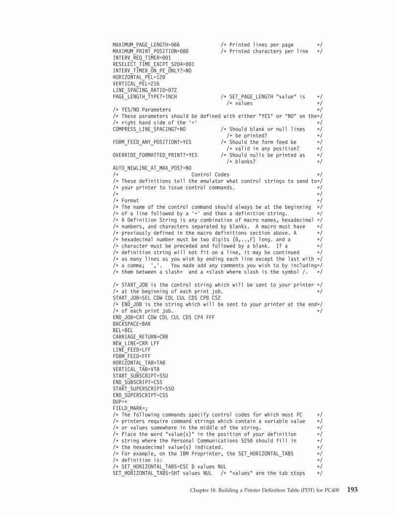
MAXIMUM_PAGE_LENGTH=066 /* Printed lines per page */MAXIMUM_PRINT_POSITION=080 /* Printed characters per line */INTERV_REQ_TIMER=001RESELECT_TIME_EXCPT_5204=001INTERV_TIMER_ON_PE_ONLY?=NOHORIZONTAL_PEL=120VERTICAL_PEL=216LINE_SPACING_RATIO=072PAGE_LENGTH_TYPE?=INCH /* SET_PAGE_LENGTH "value" is */
/* values *//* YES/NO Parameters *//* These parameters should be defined with either "YES" or "NO" on the*//* right hand side of the ’=’ */COMPRESS_LINE_SPACING?=NO /* Should blank or null lines */
/* be printed? */FORM_FEED_ANY_POSITION?=YES /* Should the form feed be */
/* valid in any position? */OVERRIDE_FORMATTED_PRINT?=YES /* Should nulls be printed as */
/* blanks? */AUTO_NEWLINE_AT_MAX_POS?=NO/* Control Codes *//* These definitions tell the emulator what control strings to send to*//* your printer to issue control commands. *//* *//* Format *//* The name of the control command should always be at the beginning *//* of a line followed by a ’=’ and then a definition string. *//* A Definition String is any combination of macro names, hexadecimal *//* numbers, and characters separated by blanks. A macro must have *//* previously defined in the macro definitions section above. A *//* hexadecimal number must be two digits (0,..,F) long. and a *//* character must be preceded and followed by a blank. If a *//* definition string will not fit on a line, it may be continued *//* as many lines as you wish by ending each line except the last with *//* a comma; ’,’. You made add any comments you wish to by including*//* them between a slash* and a *slash where slash is the symbol /. */
/* START_JOB is the control string which will be sent to your printer *//* at the beginning of each print job. */START_JOB=SEL CDW CDL CUL CDS CP8 CS2/* END_JOB is the string which will be sent to your printer at the end*//* of each print job. */END_JOB=CAT CDW CDL CUL CDS CP4 FFFBACKSPACE=BAKBEL=BELCARRIAGE_RETURN=CRRNEW_LINE=CRR LFFLINE_FEED=LFFFORM_FEED=FFFHORIZONTAL_TAB=TABVERTICAL_TAB=VTBSTART_SUBSCRIPT=SSUEND_SUBSCRIPT=CSSSTART_SUPERSCRIPT=SSOEND_SUPERSCRIPT=CSSDUP=*FIELD_MARK=;/* The following commands specify control codes for which most PC *//* printers require command strings which contain a variable value *//* or values somewhere in the middle of the string. *//* Place the word "value(s)" in the position of your definition *//* string where the Personal Communications 5250 should fill in *//* the hexadecimal value(s) indicated. *//* For example, on the IBM Proprinter, the SET_HORIZONTAL_TABS *//* definition is: *//* SET_HORIZONTAL_TABS=ESC D values NUL */SET_HORIZONTAL_TABS=SHT values NUL /* "values" are the tab stops */
Chapter 18. Building a Printer Definition Table (PDT) for PC400 193

/* in column numbers */SET_VERTICAL_TABS=SVT values NUL /* "values" are the tab stops */
/* in line numbers */SET_HORIZONTAL_MARGINS=SET_PAGE_LENGTH=SFL value /* "value"=inch of the page */SET_AUTO_PERFORATION_SKIP=SSP value
/* "value"=number of lines to *//* skip over the perforation *//* between pages. Used to set *//* top and bottom margins. */
SET_VARIABLE_LINE_DENSITY=ESC A value ESC 2/* "value"=number of points. *//* A point is *//* 1/(LINE_SPACING_RATIO) inch.*/
SET_CHARACTER_SET=/*SET_CHARACTER_SET=ESC I NULL selects the normal font *//*SET_CHARACTER_SET=ESC I 02 selects the NLQ (near letter quality) *//*SET_CHARACTER_SET=ESC I 04 selects the normal downloaded font *//*SET_CHARACTER_SET=ESC I 06 selects the NLQ downloaded font *//*SET_CHARACTER_SET=CS1 selects the Character set 1 *//*SET_CHARACTER_SET=CS2 selects the Character set 2 */
/* These control codes set the printer lines per inch and characters *//* per inch to fixed amounts. *//* If your printer does not support setting the line density in points*//* then you can enter control strings for the following commands. *//* When Personal Communications 5250 gets a command from the host to *//* set the lines per inch, it will round it to the closest line per *//* inch setting that you provide. Note that if you provide a command *//* for the SET_VARIABLE_LINE_DENSITY command above that it will be *//* used and any control strings you provide for the set lines per inch*//* commands below will not be used. */
SET_2_LINES_PER_INCH=LL2SET_3_LINES_PER_INCH=LL3SET_4_LINES_PER_INCH=LL4SET_6_LINES_PER_INCH=LL6SET_8_LINES_PER_INCH=LL8SET_10_LINES_PER_INCH=LL0 /* 7/72 inch or 9/96 inch */SET_10_CHARACTERS_PER_INCH=P10SET_12_CHARACTERS_PER_INCH=P12SET_13_CHARACTERS_PER_INCH= /* */SET_15_CHARACTERS_PER_INCH= /* The proprinter does not */
/* support 15 pitch except in *//* graphic mode */
SET_17_CHARACTERS_PER_INCH=P17 /* Condensed mode */SET_20_CHARACTERS_PER_INCH=START_DOUBLE_WIDTH_CHARACTERS=P05END_DOUBLE_WIDTH_CHARACTERS=CDW
/* These control codes are used to select the source drawer number *//* when your printer has the dual drawer sheetfeed option. */SELECT_DRAWER1=SD1SELECT_DRAWER2=SD2SELECT_DRAWER3=SELECT_ENVELOPE=ENV /* Envelope */
/* These control codes select the print mode (quality of print). */SELECT_DRAFT_QUALITY=SELECT_LETTER_QUALITY=SELECT_ENHANCED_QUALITY=SELECT_SETUP_QUALITY=
/* These control codes */SET_DUPLEX=SET_DUPLEX_TUMBLE=RESET_DUPLEX=
194 Personal Communications Administrator’s Guide and Reference
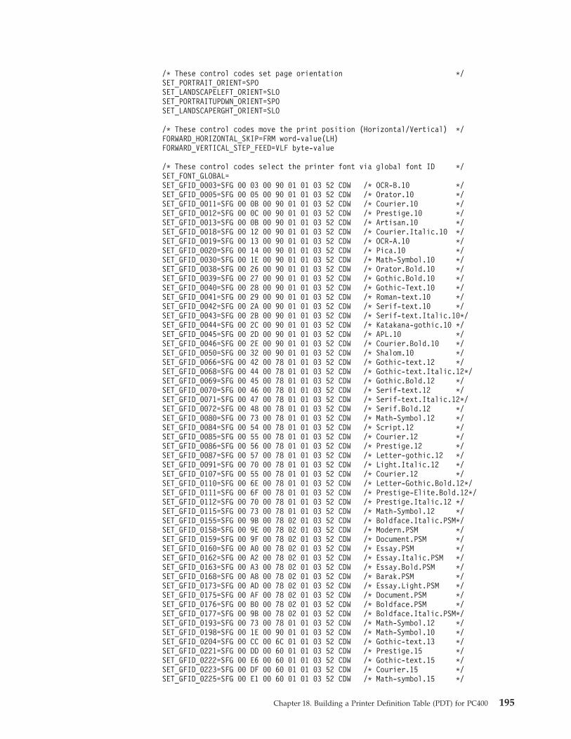
/* These control codes set page orientation */SET_PORTRAIT_ORIENT=SPOSET_LANDSCAPELEFT_ORIENT=SLOSET_PORTRAITUPDWN_ORIENT=SPOSET_LANDSCAPERGHT_ORIENT=SLO
/* These control codes move the print position (Horizontal/Vertical) */FORWARD_HORIZONTAL_SKIP=FRM word-value(LH)FORWARD_VERTICAL_STEP_FEED=VLF byte-value
/* These control codes select the printer font via global font ID */SET_FONT_GLOBAL=SET_GFID_0003=SFG 00 03 00 90 01 01 03 52 CDW /* OCR-B.10 */SET_GFID_0005=SFG 00 05 00 90 01 01 03 52 CDW /* Orator.10 */SET_GFID_0011=SFG 00 0B 00 90 01 01 03 52 CDW /* Courier.10 */SET_GFID_0012=SFG 00 0C 00 90 01 01 03 52 CDW /* Prestige.10 */SET_GFID_0013=SFG 00 0B 00 90 01 01 03 52 CDW /* Artisan.10 */SET_GFID_0018=SFG 00 12 00 90 01 01 03 52 CDW /* Courier.Italic.10 */SET_GFID_0019=SFG 00 13 00 90 01 01 03 52 CDW /* OCR-A.10 */SET_GFID_0020=SFG 00 14 00 90 01 01 03 52 CDW /* Pica.10 */SET_GFID_0030=SFG 00 1E 00 90 01 01 03 52 CDW /* Math-Symbol.10 */SET_GFID_0038=SFG 00 26 00 90 01 01 03 52 CDW /* Orator.Bold.10 */SET_GFID_0039=SFG 00 27 00 90 01 01 03 52 CDW /* Gothic.Bold.10 */SET_GFID_0040=SFG 00 28 00 90 01 01 03 52 CDW /* Gothic-Text.10 */SET_GFID_0041=SFG 00 29 00 90 01 01 03 52 CDW /* Roman-text.10 */SET_GFID_0042=SFG 00 2A 00 90 01 01 03 52 CDW /* Serif-text.10 */SET_GFID_0043=SFG 00 2B 00 90 01 01 03 52 CDW /* Serif-text.Italic.10*/SET_GFID_0044=SFG 00 2C 00 90 01 01 03 52 CDW /* Katakana-gothic.10 */SET_GFID_0045=SFG 00 2D 00 90 01 01 03 52 CDW /* APL.10 */SET_GFID_0046=SFG 00 2E 00 90 01 01 03 52 CDW /* Courier.Bold.10 */SET_GFID_0050=SFG 00 32 00 90 01 01 03 52 CDW /* Shalom.10 */SET_GFID_0066=SFG 00 42 00 78 01 01 03 52 CDW /* Gothic-text.12 */SET_GFID_0068=SFG 00 44 00 78 01 01 03 52 CDW /* Gothic-text.Italic.12*/SET_GFID_0069=SFG 00 45 00 78 01 01 03 52 CDW /* Gothic.Bold.12 */SET_GFID_0070=SFG 00 46 00 78 01 01 03 52 CDW /* Serif-text.12 */SET_GFID_0071=SFG 00 47 00 78 01 01 03 52 CDW /* Serif-text.Italic.12*/SET_GFID_0072=SFG 00 48 00 78 01 01 03 52 CDW /* Serif.Bold.12 */SET_GFID_0080=SFG 00 73 00 78 01 01 03 52 CDW /* Math-Symbol.12 */SET_GFID_0084=SFG 00 54 00 78 01 01 03 52 CDW /* Script.12 */SET_GFID_0085=SFG 00 55 00 78 01 01 03 52 CDW /* Courier.12 */SET_GFID_0086=SFG 00 56 00 78 01 01 03 52 CDW /* Prestige.12 */SET_GFID_0087=SFG 00 57 00 78 01 01 03 52 CDW /* Letter-gothic.12 */SET_GFID_0091=SFG 00 70 00 78 01 01 03 52 CDW /* Light.Italic.12 */SET_GFID_0107=SFG 00 55 00 78 01 01 03 52 CDW /* Courier.12 */SET_GFID_0110=SFG 00 6E 00 78 01 01 03 52 CDW /* Letter-Gothic.Bold.12*/SET_GFID_0111=SFG 00 6F 00 78 01 01 03 52 CDW /* Prestige-Elite.Bold.12*/SET_GFID_0112=SFG 00 70 00 78 01 01 03 52 CDW /* Prestige.Italic.12 */SET_GFID_0115=SFG 00 73 00 78 01 01 03 52 CDW /* Math-Symbol.12 */SET_GFID_0155=SFG 00 9B 00 78 02 01 03 52 CDW /* Boldface.Italic.PSM*/SET_GFID_0158=SFG 00 9E 00 78 02 01 03 52 CDW /* Modern.PSM */SET_GFID_0159=SFG 00 9F 00 78 02 01 03 52 CDW /* Document.PSM */SET_GFID_0160=SFG 00 A0 00 78 02 01 03 52 CDW /* Essay.PSM */SET_GFID_0162=SFG 00 A2 00 78 02 01 03 52 CDW /* Essay.Italic.PSM */SET_GFID_0163=SFG 00 A3 00 78 02 01 03 52 CDW /* Essay.Bold.PSM */SET_GFID_0168=SFG 00 A8 00 78 02 01 03 52 CDW /* Barak.PSM */SET_GFID_0173=SFG 00 AD 00 78 02 01 03 52 CDW /* Essay.Light.PSM */SET_GFID_0175=SFG 00 AF 00 78 02 01 03 52 CDW /* Document.PSM */SET_GFID_0176=SFG 00 B0 00 78 02 01 03 52 CDW /* Boldface.PSM */SET_GFID_0177=SFG 00 9B 00 78 02 01 03 52 CDW /* Boldface.Italic.PSM*/SET_GFID_0193=SFG 00 73 00 78 01 01 03 52 CDW /* Math-Symbol.12 */SET_GFID_0198=SFG 00 1E 00 90 01 01 03 52 CDW /* Math-Symbol.10 */SET_GFID_0204=SFG 00 CC 00 6C 01 01 03 52 CDW /* Gothic-text.13 */SET_GFID_0221=SFG 00 DD 00 60 01 01 03 52 CDW /* Prestige.15 */SET_GFID_0222=SFG 00 E6 00 60 01 01 03 52 CDW /* Gothic-text.15 */SET_GFID_0223=SFG 00 DF 00 60 01 01 03 52 CDW /* Courier.15 */SET_GFID_0225=SFG 00 E1 00 60 01 01 03 52 CDW /* Math-symbol.15 */
Chapter 18. Building a Printer Definition Table (PDT) for PC400 195

SET_GFID_0229=SFG 00 E5 00 60 01 01 03 52 CDW /* Serif-text.15 */SET_GFID_0230=SFG 00 E6 00 60 01 01 03 52 CDW /* Gothic-text.15 */SET_GFID_0245=SFG 00 2E 00 90 01 01 03 52 P05 /* Courier.Bold.5 */SET_GFID_0252=SFG 00 FC 00 54 01 01 03 52 CDW /* Courier.15 */SET_GFID_0253=SFG 00 FD 00 54 01 01 03 52 CDW /* Courier.Bold.17 */SET_GFID_0254=SFG 00 FE 00 55 01 01 03 52 CDW /* Courier.17 */SET_GFID_0280=SFG 01 18 00 48 01 01 03 52 CDW /* APL.20 */SET_GFID_0281=SFG 01 19 00 48 01 01 03 52 CDW /* Gothic-text.20 */SET_GFID_0290=SFG 01 22 00 36 01 01 03 52 CDW /* Gothic-text.27 */SET_GFID_0751=SFG 11 37 00 A0 01 03 03 52 CDW /* Sonoran-serif.8pt */SET_GFID_1051=SFG 11 37 00 C8 01 03 03 52 CDW /* Sonoran-serif.10pt */SET_GFID_1053=SFG 11 4B 00 C8 01 03 03 52 CDW /* Sonoran-serif.bold.10pt*/SET_GFID_1056=SFG 11 B7 00 C8 01 03 03 52 CDW /* Sonoran-serif.italic.10pt*/SET_GFID_1351=SFG 11 37 00 F0 01 03 03 52 CDW /* Sonoran-serif.12pt */SET_GFID_1653=SFG 11 4B 01 40 01 03 03 52 CDW /* Sonoran-serif.Bold.16pt*/SET_GFID_2103=SFG 11 4B 01 E0 01 03 03 52 CDW /* Sonoran-serif.Bold.24pt*/
/* Color Specifications */START_COLOR_BLUE=END_COLOR_BLUE=START_COLOR_GREEN=END_COLOR_GREEN=START_COLOR_CYAN=END_COLOR_CYAN=START_COLOR_RED=END_COLOR_RED=START_COLOR_MAGENTA=END_COLOR_MAGENTA=START_COLOR_YELLOW=END_COLOR_YELLOW=START_COLOR_BLACK=END_COLOR_BLACK=START_COLOR_WHITE=END_COLOR_WHITE=
/* Highlight Specifications *//* These definitions will determine how things which are sent by the *//* host to be displayed or printed as underlined, reverse video, or *//* blinking will be highlighted on your printer. */
START_HIGHLIGHT_INTENSE=SDS /* This is double strike */END_HIGHLIGHT_INTENSE=CDSSTART_HIGHLIGHT_UNDERLINE=SULEND_HIGHLIGHT_UNDERLINE=CULSTART_HIGHLIGHT_REVERSE_VIDEO=END_HIGHLIGHT_REVERSE_VIDEO=START_HIGHLIGHT_BLINK=END_HIGHLIGHT_BLINK=
/* Character Definitions */SPACE=SPAEXCLAMATION_POINT=21QUOTATION_MARKS=22NUMBER_SIGN=23DOLLAR_SIGN=24PERCENT_SIGN=25AMPERSAND=26APOSTROPHE=27LEFT_PARENTHESIS=28RIGHT_PARENTHESIS=29ASTERISK=2APLUS_SIGN=2BCOMMA=2CHYPHEN=2DPERIOD=2ESLASH=2FZERO=0
196 Personal Communications Administrator’s Guide and Reference

ONE=1TWO=2THREE=3FOUR=4FIVE=5SIX=6SEVEN=7EIGHT=8NINE=9COLON=3ASEMICOLON=3BLESS_THAN_SIGN=3CEQUAL_SIGN=3DGREATER_THAN_SIGN=3EQUESTION_MARK=3FAT_SIGN=40A_CAPITAL=AB_CAPITAL=BC_CAPITAL=CD_CAPITAL=DE_CAPITAL=EF_CAPITAL=FG_CAPITAL=GH_CAPITAL=HI_CAPITAL=IJ_CAPITAL=JK_CAPITAL=KL_CAPITAL=LM_CAPITAL=MN_CAPITAL=NO_CAPITAL=OP_CAPITAL=PQ_CAPITAL=QR_CAPITAL=RS_CAPITAL=ST_CAPITAL=TU_CAPITAL=UV_CAPITAL=VW_CAPITAL=WX_CAPITAL=XY_CAPITAL=YZ_CAPITAL=ZLEFT_BRACKET=5BBACKSLASH=5CRIGHT_BRACKET=5DCIRCUMFLEX_ACCENT=5EUNDERLINE=5FGRAVE_ACCENT=60A_SMALL=aB_SMALL=bC_SMALL=cD_SMALL=dE_SMALL=eF_SMALL=fG_SMALL=gH_SMALL=hI_SMALL=iJ_SMALL=jK_SMALL=kL_SMALL=lM_SMALL=mN_SMALL=nO_SMALL=oP_SMALL=pQ_SMALL=qR_SMALL=rS_SMALL=s
Chapter 18. Building a Printer Definition Table (PDT) for PC400 197

T_SMALL=tU_SMALL=uV_SMALL=vW_SMALL=wX_SMALL=xY_SMALL=yZ_SMALL=zLEFT_BRACE=7BVERTICAL_BAR=7CRIGHT_BRACE=7DTILDE_ACCENT=7EC_CEDILLA_CAPITAL=80U_DIAERESIS_SMALL=81E_ACUTE_SMALL=82A_CIRCUMFLEX_SMALL=83A_DIAERESIS_SMALL=84A_GRAVE_SMALL=85A_OVERCIRCLE_SMALL=86C_CEDILLA_SMALL=87E_CIRCUMFLEX_SMALL=88E_DIAERESIS_SMALL=89E_GRAVE_SMALL=8AI_DIAERESIS_SMALL=8BI_CIRCUMFLEX_SMALL=8CI_GRAVE_SMALL=8DA_DIAERESIS_CAPITAL=8EA_OVERCIRCLE_CAPITAL=8FE_ACUTE_CAPITAL=90AE_DIPTHONG_SMALL=91AE_DIPTHONG_CAPITAL=92O_CIRCUMFLEX_SMALL=93O_DIAERESIS_SMALL=94O_GRAVE_SMALL=95U_CIRCUMFLEX_SMALL=96U_GRAVE_SMALL=97Y_DIAERESIS_SMALL=98O_DIAERESIS_CAPITAL=99U_DIAERESIS_CAPITAL=9AO_SLASH_SMALL=9BPOUND_SIGN=9CO_SLASH_CAPITAL=9DMULTIPLY_SIGN=9EA_ACUTE_SMALL=A0I_ACUTE_SMALL=A1O_ACUTE_SMALL=A2U_ACUTE_SMALL=A3N_TILDE_SMALL=A4N_TILDE_CAPITAL=A5ORDINAL_INDICATOR_FEMININE=A6ORDINAL_INDICATOR_MASCULINE=A7QUESTION_MARK_INVERTED=A8REGISTERED_TRADEMARK_SYMBOL=A9LOGICAL_NOT=AAONE_HALF=ABONE_QUARTER=ACEXCLAMATION_POINT_INVERTED=ADLEFT_ANGLE_QUOTES=AERIGHT_ANGLE_QUOTES=AFA_ACUTE_CAPITAL=B5A_CIRCUMFLEX_CAPITAL=B6A_GRAVE_CAPITAL=B7COPYRIGHT_SYMBOL=B8CENT_SIGN=BDYEN_SIGN=BEA_TILDE_SMALL=C6A_TILDE_CAPITAL=C7INTERNATIONAL_CURRENCY_SYMBOL=CF
198 Personal Communications Administrator’s Guide and Reference

ETH_ICELANDIC_SMALL=D0ETH_ICELANDIC_CAPITAL=D1E_CIRCUMFLEX_CAPITAL=D2E_DIAERESIS_CAPITAL=D3E_GRAVE_CAPITAL=D4I_DOTLESS_SMALL=D5I_ACUTE_CAPITAL=D6I_CIRCUMFLEX_CAPITAL=D7I_DIAERESIS_CAPITAL=D8VERTICAL_LINE_BROKEN=DDI_GRAVE_CAPITAL=DEO_ACUTE_CAPITAL=E0SHARP_S_SMALL=E1O_CIRCUMFLEX_CAPITAL=E2O_GRAVE_CAPITAL=E3O_TILDE_SMALL=E4O_TILDE_CAPITAL=E5MICRO_SYMBOL=E6THORN_ICELANDIC_SMALL=E7THORN_ICELANDIC_CAPITAL=E8U_ACUTE_CAPITAL=E9U_CIRCUMFLEX_CAPITAL=EAU_GRAVE_CAPITAL=EBY_ACUTE_SMALL=ECY_ACUTE_CAPITAL=EDOVERLINE=EEACUTE_ACCENT=EFSYLLABLE_HYPHEN=F0PLUS_OR_MINUS_SIGN=F1THREE_QUARTERS=F3PARAGRAPH_SYMBOL=F4SECTION_SYMBOL=F5DIVIDE_SIGN=F6CEDILLA=F7DEGREE_SYMBOL=F8DIAERESIS=F9MIDDLE_DOT_ACCENT=FAONE_SUPERSCRIPT=FBTHREE_SUPERSCRIPT=FCTWO_SUPERSCRIPT=FDREQUIRED_SPACE=SPA/**********************************************************************//* PC5250 Internal Data Area. *//* Do not change these statements. *//**********************************************************************/TOP_MARGIN=LEFT_MARGIN=DYNAMIC_START_JOB=00 00 00 00 00 00 00 00 00 00 00DYNAMIC_END_JOB=00 00DYNAMIC_SET_PAGE_LENGTH=00 00 00PRINTER_ID=40 19/* End of Definition File */
IBM5577.PDF File Contents/**********************************************************************//* PDF FILE (PRINTER DEFINITION FILE) FOR: PS/55 Printer *//**********************************************************************/BEGIN_MACROSNUL EQU 00BEL EQU 07BAK EQU 08TAB EQU 09LFF EQU 0AVTB EQU 0BFFF EQU 0CCRR EQU 0D
Chapter 18. Building a Printer Definition Table (PDT) for PC400 199

SEL EQU 11DC3 EQU 13ESC EQU 1BCAN EQU 18SPA EQU 20P10 EQU 1B 7E 02 00 01 32P12 EQU 1B 7E 02 00 01 3CP13 EQU 1B 7E 02 00 01 43P15 EQU 1B 7E 02 00 01 4BSDW EQU 1B 7E 0E 00 01 09EDW EQU 1B 7E 0E 00 01 0ASVT EQU 1B 7E 19SHT EQU 1B 7E 18CSS EQU 1B 7E 0E 00 01 0FSSO EQU 1B 7E 0E 00 01 0DSSU EQU 1B 7E 0E 00 01 0ESUL EQU 1B 7E 11 00 01 01CUL EQU 1B 7E 11 00 01 00LL2 EQU 1B 7E 03 00 01 14LL3 EQU 1B 7E 03 00 01 1ELL4 EQU 1B 7E 03 00 01 28LL6 EQU 1B 7E 03 00 01 3CLL7 EQU 1B 7E 03 00 01 4BLL8 EQU 1B 7E 03 00 01 50SPL EQU 1B 7E 04 00 03 00INZ EQU 1B 7E 01 00 00EJC EQU 1B 7E 0E 00 01 06END_MACROS/**********************************************************************//* Session Parameters *//**********************************************************************/MAXIMUM_PAGE_LENGTH=066MAXIMUM_PRINT_POSITION=132DEFAULT_CPI?=010DEFAULT_LPI?=006COMPRESS_LINE_SPACING?=NOFORM_FEED_ANY_POSITION?=YESOVERRIDE_FORMATTED_PRINT?=YESHORIZONTAL_PEL=180VERTICAL_PEL=120UNITS_OF_DRAW_LINE=KANJI_CODE?=SHIFT_JISZENKAKU_SPACE=PAGE_LENGTH_TYPE?=6INCH/**********************************************************************//* Control Codes *//**********************************************************************/START_JOB=INZ SEL LL6 P10END_JOB=INZBACKSPACE=BAKBEL=BELCARRIAGE_RETURN=CRRNEW_LINE=CRR LFFLINE_FEED=LFFFORM_FEED=EJCHORIZONTAL_TAB=TABVERTICAL_TAB=VTBDESELECT=DC3START_SUBSCRIPT=SSUEND_SUBSCRIPT=CSSSTART_SUPERSCRIPT=SSOEND_SUPERSCRIPT=CSSDUP=*FIELD_MARK=;SET_HORIZONTAL_TABS=SHT length(HL)-valuesSET_VERTICAL_TABS=SVT length(HL)-valuesSET_HORIZONTAL_MARGINS=
200 Personal Communications Administrator’s Guide and Reference

SET_PAGE_LENGTH=SPL word-value(HL)SET_2_LINES_PER_INCH=LL2SET_3_LINES_PER_INCH=LL3SET_4_LINES_PER_INCH=LL4SET_6_LINES_PER_INCH=LL6SET_7.5_LINES_PER_INCH=LL7SET_8_LINES_PER_INCH=LL8SET_10_CHARACTERS_PER_INCH=P10SET_12_CHARACTERS_PER_INCH=P12SET_13.4_CHARACTERS_PER_INCH=P13SET_15_CHARACTERS_PER_INCH=P15START_DOUBLE_WIDTH_CHARACTERS=SDWEND_DOUBLE_WIDTH_CHARACTERS=EDWIMAGE_TRANSMISSION=1B 25 31 length(HL)-imagesFORWARD_HORIZONTAL_SKIP=1B 25 33 word-value(HL)FORWARD_VERTICAL_STEP_FEED=1B 25 35 word-value(HL)SET_FONT_SIZE=1B 7E 20 00 03 word-value(HL) 02SET_TATEGAKI_MODE=1B 7E 0E 00 01 0BRESET_TATEGAKI_MODE=1B 7E 0E 00 01 0CSBCS_FONT_LOAD=1B 7E 81 00 28 F0 40 00 18 byte-values F0 40DBCS_FONT_LOAD=1B 7E 81 00 4C F0 40 02 18 byte-values F0 40SELECT_DRAWER=SET_LOCAL_FONT=RESET_LOCAL_FONT=ABS_HORIZONTAL_COLUMN_SKIP=1B 7E 1C 00 02 00 byte-valueREL_HOR_COLUMN_SKIP_TO_RIGHT=1B 7E 1C 00 02 01 byte-valueSET_SOLID_LINE_TYPE=SET_DOTTED_LINE_TYPE=SET_LINE_WIDTH_THIN=SET_LINE_WIDTH_BOLD=DRAW_LINE=KANJI_ON=KANJI_OFF=ATTRIBUTE_GRID_LINE=1B 7E 16 length(HL)-values/**********************************************************************//* Highlight Specifications *//**********************************************************************/START_HIGHLIGHT_INTENSE=ESC 7E 0E 00 01 17END_HIGHLIGHT_INTENSE=ESC 7E 0E 00 01 18START_HIGHLIGHT_UNDERLINE=1B 7E 11 00 01 01END_HIGHLIGHT_UNDERLINE=1B 7E 11 00 01 00/**********************************************************************//* Internal Data Area. *//* Do not change these statement. *//**********************************************************************/TOP_MARGIN=LEFT_MARGIN=DYNAMIC_START_JOB=00 00 00 00 00 00 00 00 00 00 00DYNAMIC_END_JOB=00 00DYNAMIC_SET_PAGE_LENGTH=00 00 00PRINTER_ID=55 77/* End of Definition File */
Field Names of Printer Definition FilesTable 23 lists the field names of the printer definition files (PDF files) and theirmeanings:
Table 23. Field Names of PDF Files
Field Name Meaning Remarks
MAXIMUM_PAGE_LENGTH Default MPL Default is 66
MAXIMUM_PRINT_POSITION Default MPP Default is 132
DEFAULT_CPI? Default CPI Default is 10
Chapter 18. Building a Printer Definition Table (PDT) for PC400 201
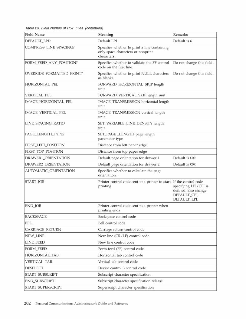
Table 23. Field Names of PDF Files (continued)
Field Name Meaning Remarks
DEFAULT_LPI? Default LPI Default is 6
COMPRESS_LINE_SPACING? Specifies whether to print a line containingonly space characters or nonprintcharacters.
FORM_FEED_ANY_POSITION? Specifies whether to validate the FF controlcode on the first line.
Do not change this field.
OVERRIDE_FORMATTED_PRINT? Specifies whether to print NULL charactersas blanks.
Do not change this field.
HORIZONTAL_PEL FORWARD_HORIZONTAL_SKIP lengthunit
VERTICAL_PEL FORWARD_VERTICAL_SKIP length unit
IMAGE_HORIZONTAL_PEL IMAGE_TRANSMISSION horizontal lengthunit
IMAGE_VERTICAL_PEL IMAGE_TRANSMISSION vertical lengthunit
LINE_SPACING_RATIO SET_VARIABLE_LINE_DENSITY lengthunit
PAGE_LENGTH_TYPE? SET_PAGE _LENGTH page lengthparameter type
FIRST_LEFT_POSITION Distance from left paper edge
FIRST_TOP_POSITION Distance from top paper edge
DRAWER1_ORIENTATION Default page orientation for drawer 1 Default is COR
DRAWER2_ORIENTATION Default page orientation for drawer 2 Default is COR
AUTOMATIC_ORIENTATION Specifies whether to calculate the pageorientation.
START_JOB Printer control code sent to a printer to startprinting
If the control codespecifying LPI/CPI isdefined, also changeDEFAULT_CPI,DEFAULT_LPI.
END_JOB Printer control code sent to a printer whenprinting ends
BACKSPACE Backspace control code
BEL Bell control code
CARRIAGE_RETURN Carriage return control code
NEW_LINE New line (CR/LF) control code
LINE_FEED New line control code
FORM_FEED Form feed (FF) control code
HORIZONTAL_TAB Horizontal tab control code
VERTICAL_TAB Vertical tab control code
DESELECT Device control 3 control code
START_SUBSCRIPT Subscript character specification
END_SUBSCRIPT Subscript character specification release
START_SUPERSCRIPT Superscript character specification
202 Personal Communications Administrator’s Guide and Reference

Table 23. Field Names of PDF Files (continued)
Field Name Meaning Remarks
END_SUPERSCRIPT Superscript character specification release
DUP Character used for printing DUP codes
FIELD_MARK Character used for printing FIELD MARKcharacters
SET_HORIZONTAL_TABS Horizontal tab setup Do not change this field.
SET_VERTICAL_TABS Vertical tab setup Do not change this field.
SET_HORIZONTAL_MARGINS Right and left margin setup Do not change this field.
SET_PAGE_LENGTH Page length setup Assign the unit used forthe defined control codepage length to thePAGE_LENGTH_TYPEfield. When single sheetsare to be used, delete thisfield.
SET_VARIABLE_LINE_DENSITY Line density setup Assign the unit used forthe control code lengthdefined toLINE_SPACING_RATIOfield.
SET_2_LINES_PER_INCH New line pitch (2LPI) setup
SET_3_LINES_PER_INCH New line pitch (3LPI) setup
SET_4_LINES_PER_INCH New line pitch (4LPI) setup
SET_6_LINES_PER_INCH New line pitch (6LPI) setup
SET_8_LINES_PER_INCH New line pitch (8LPI) setup
SET_10_LINES_PER_INCH New line pitch (10LPI) setup
SET_10_CHARACTERS_PER_INCH Character pitch (10CPI) setup
SET_12_CHARACTERS_PER_INCH Character pitch (12CPI) setup
SET_13_CHARACTERS_PER_INCH Character pitch (13CPI) setup
SET_15_CHARACTERS_PER_INCH Character pitch (15CPI) setup
SET_17_CHARACTERS_PER_INCH Character pitch (17CPI) setup
SET_20_CHARACTERS_PER_INCH Character pitch (20CPI) setup
IMAGE_TRANSMISSION Image data setup (vertical 24-dot image)
SELECT_DRAWER1 Page tray (Primary) setup
SELECT_DRAWER2 Page tray (Alternate) setup
SELECT_ENVELOPE Envelope tray setup
SELECT_DRAFT_QUALITY Draft print quality setup
SELECT_LETTER_QUALITY Letter print quality setup
SELECT_ENHANCED_QUALITY Enhanced print quality setup
SET_DUPLEX Duplex printing setup
SET_DUPLEX_TUMBLE Duplex (tumble) printing setup
RESET_DUPLEX Duplex printing release
SET_PORTRAIT_ORIENT Page orientation (Normal portrait (upright))setup
Chapter 18. Building a Printer Definition Table (PDT) for PC400 203

Table 23. Field Names of PDF Files (continued)
Field Name Meaning Remarks
SET_LANDSCAPELEFT_ORIENT Page orientation (Landscape left (270 degreeclockwise rotation of text)) setup
SET_PORTRAITUPDWN_ORIENT Page orientation (Portrait upside down (180degree clockwise rotation of text)) setup
SET_LANDSCAPERGHT_ORIENT Page orientation (Landscape right (90degree clockwise rotation of text)) setup
FORWARD_HORIZONTAL_SKIP Variable skip (relative position/dot unit) Assign the unit of thedefined control codelength to theHORIZONTAL_PEL field.
FORWARD_VERTICAL_STEP_FEED Variable line feed (relative position/dotunit)
Assign the unit of thedefined control codelength to theVERTICAL_PEL field.
SET_FONT_GLOBAL Global font ID setup Do not change this field.
SET_GFID_0003 GFID 3 (OCR-B) setup
SET_GFID_0005 GFID 5 (Orator) setup
SET_GFID_0011 GFID 11 (Courier 10) setup
SET_GFID_0012 GFID 12 (Prestige Pica) setup
SET_GFID_0013 GFID 13 (Artisan 10) setup
SET_GFID_0018 GFID 18 (Courier Italic 10) setup
SET_GFID_0019 GFID 19 (OCR-A) setup
SET_GFID_0020 GFID 20 (Pica) setup
SET_GFID_0030 GFID 30 (Math Symbol 10) setup
SET_GFID_0038 GFID 38 (Orator Bold) setup
SET_GFID_0039 GFID 39 (Gothic Bold 10) setup
SET_GFID_0040 GFID 40 (Gothic Text 10) setup
SET_GFID_0041 GFID 41 (Roman Text 10) setup
SET_GFID_0042 GFID 42 (Serif Text 10) setup
SET_GFID_0043 GFID 43 (Serif Italic 10) setup
SET_GFID_0044 GFID 44 (Katakana 10) setup
SET_GFID_0045 GFID 45 (APL 10) setup
SET_GFID_0046 GFID 46 (Courier Bold 10) setup
SET_GFID_0050 GFID 50 (Shalom 10) setup
SET_GFID_0066 GFID 66 (Gothic Text 12) setup
SET_GFID_0068 GFID 68 (Gothic Italic 12) setup
SET_GFID_0069 GFID 69 (Gothic Bold 12) setup
SET_GFID_0070 GFID 70 (Serif Text 12) setup
SET_GFID_0071 GFID 71 (Serif Italic 12) setup
SET_GFID_0072 GFID 72 (Serif Bold 12) setup
SET_GFID_0080 GFID 80 (Math Symbol 12) setup
SET_GFID_0084 GFID 84 (Script 12) setup
SET_GFID_0085 GFID 85 (Courier 12) setup
204 Personal Communications Administrator’s Guide and Reference

Table 23. Field Names of PDF Files (continued)
Field Name Meaning Remarks
SET_GFID_0086 GFID 86 (Prestige Elite) setup
SET_GFID_0087 GFID 87 (Letter Gothic 12) setup
SET_GFID_0091 GFID 91 (Light Italic 12) setup
SET_GFID_0110 GFID 110 (Letter Gothic Bold 12) setup
SET_GFID_0111 GFID 111 (Prestige Elite Bold) setup
SET_GFID_0112 GFID 112 (Prestige Elite Italic) setup
SET_GFID_0115 GFID 115 (Math Symbol 12) setup
SET_GFID_0155 GFID 155 (Boldface Italic) setup
SET_GFID_0158 GFID 158 (Modern) setup
SET_GFID_0159 GFID 159 (Boldface) setup
SET_GFID_0160 GFID 160 (Essay) setup
SET_GFID_0162 GFID 162 (Essay Italic) setup
SET_GFID_0163 GFID 163 (Essay Bold) setup
SET_GFID_0168 GFID 168 (Barak PSM) setup
SET_GFID_0173 GFID 173 (Essay Light) setup
SET_GFID_0175 GFID 175 (Document) setup
SET_GFID_0176 GFID 176 (Boldface) setup
SET_GFID_0177 GFID 177 (Boldface Italic) setup
SET_GFID_0193 GFID 193 (Math Symbol 12) setup
SET_GFID_0198 GFID 198 (Math Symbol 10) setup
SET_GFID_0204 GFID 204 (Gothic Text 13) setup
SET_GFID_0221 GFID 221 (Prestige 15) setup
SET_GFID_0222 GFID 222 (Gothic Text 15) setup
SET_GFID_0223 GFID 223 (Courier 15) setup
SET_GFID_0225 GFID 225 (Math Symbol 15) setup
SET_GFID_0229 GFID 229 (Serif Text 15) setup
SET_GFID_0230 GFID 230 (Gothic Text 15) setup
SET_GFID_0245 GFID 245 (Courier Bold 5) setup
SET_GFID_0252 GFID 252 (Courier 17) setup
SET_GFID_0253 GFID 253 (Courier Bold 17) setup
SET_GFID_0254 GFID 254 (Courier 17 (sub/super)) setup
SET_GFID_0280 GFID 280 (APL 20) setup
SET_GFID_0281 GFID 281 (Gothic Text 20) setup
SET_GFID_0290 GFID 290 (Gothic Text 27) setup
SET_GFID_0751 GFID 751 (Sonoran-Serif 8-pt RomanMedium) setup
SET_GFID_1051 GFID 1051 (Sonoran-Serif 10-pt RomanMedium) setup
SET_GFID_1053 GFID 1053 (Sonoran-Serif 10-pt RomanBold) setup
Chapter 18. Building a Printer Definition Table (PDT) for PC400 205
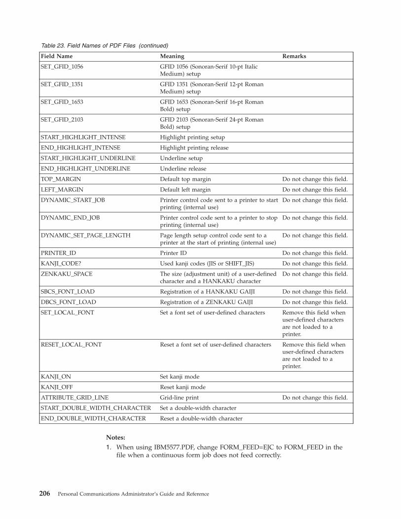
Table 23. Field Names of PDF Files (continued)
Field Name Meaning Remarks
SET_GFID_1056 GFID 1056 (Sonoran-Serif 10-pt ItalicMedium) setup
SET_GFID_1351 GFID 1351 (Sonoran-Serif 12-pt RomanMedium) setup
SET_GFID_1653 GFID 1653 (Sonoran-Serif 16-pt RomanBold) setup
SET_GFID_2103 GFID 2103 (Sonoran-Serif 24-pt RomanBold) setup
START_HIGHLIGHT_INTENSE Highlight printing setup
END_HIGHLIGHT_INTENSE Highlight printing release
START_HIGHLIGHT_UNDERLINE Underline setup
END_HIGHLIGHT_UNDERLINE Underline release
TOP_MARGIN Default top margin Do not change this field.
LEFT_MARGIN Default left margin Do not change this field.
DYNAMIC_START_JOB Printer control code sent to a printer to startprinting (internal use)
Do not change this field.
DYNAMIC_END_JOB Printer control code sent to a printer to stopprinting (internal use)
Do not change this field.
DYNAMIC_SET_PAGE_LENGTH Page length setup control code sent to aprinter at the start of printing (internal use)
Do not change this field.
PRINTER_ID Printer ID Do not change this field.
KANJI_CODE? Used kanji codes (JIS or SHIFT_JIS) Do not change this field.
ZENKAKU_SPACE The size (adjustment unit) of a user-definedcharacter and a HANKAKU character
Do not change this field.
SBCS_FONT_LOAD Registration of a HANKAKU GAIJI Do not change this field.
DBCS_FONT_LOAD Registration of a ZENKAKU GAIJI Do not change this field.
SET_LOCAL_FONT Set a font set of user-defined characters Remove this field whenuser-defined charactersare not loaded to aprinter.
RESET_LOCAL_FONT Reset a font set of user-defined characters Remove this field whenuser-defined charactersare not loaded to aprinter.
KANJI_ON Set kanji mode
KANJI_OFF Reset kanji mode
ATTRIBUTE_GRID_LINE Grid-line print Do not change this field.
START_DOUBLE_WIDTH_CHARACTER Set a double-width character
END_DOUBLE_WIDTH_CHARACTER Reset a double-width character
Notes:
1. When using IBM5577.PDF, change FORM_FEED=EJC to FORM_FEED in thefile when a continuous form job does not feed correctly.
206 Personal Communications Administrator’s Guide and Reference

2. When using ESC_P.PDF, DBCS (2-byte) characters are placed to the left of thecharacter box, not in the center. To place DBCS characters in the center of thecharacter box, change the IBM-supplied values in ESC_P.PDF:
P10 EQU 1B 50 1B 20 00 1C 53 00 0C 1C 54 00 00P12 EQU 1B 4D 1B 20 00 1C 53 00 06 1C 54 00 00P13 EQU 1B 67 1B 20 01 1C 53 00 03 1C 54 00 01P15 EQU 1B 67 1B 20 00 1C 53 00 00 1C 54 00 00
to the following:P10 EQU 1B 50 1B 20 00 1C 53 06 06 1C 54 00 00P12 EQU 1B 4D 1B 20 00 1C 53 03 03 1C 54 00 00P13 EQU 1B 67 1B 20 01 1C 53 02 01 1C 54 00 01P15 EQU 1B 67 1B 20 00 1C 53 00 00 1C 54 00 00
The following table lists the session parameter field names and their effectivevalues:
Table 24. Effective Values for PDF File Field Names
Field Name Effective Value
MAXIMUM_PAGE_LENGTH 001 to 255
MAXIMUM_PRINT_POSITION 001 to 255
DEFAULT_CPI? 010/012/015
DEFAULT_LPI? 004/006/008
COMPRESS_LINE_SPACING? YES/NO
FORM_FEED_ANY_POSITION? YES/NO
OVERRIDE_FORMATTED_PRINT? YES/NO
HORIZONTAL_PEL FORWARD_HORIZONTAL_SKIP lengthunit
VERTICAL_PEL FORWARD_VERTICAL_ STEP_FEED lengthunit
IMAGE_HORIZONTAL_PEL IMAGE_TRANSMISSION horizontal unit
IMAGE_VERTICAL_PEL IMAGE_TRANSMISSION vertical unit
LINE_SPACING_RATIO SET_VARIABLE_LINE_DENSITY length unit
PAGE_LENGTH_TYPE? LINE/INCH/6INCH*
FIRST_LEFT_POSITION 000 to 1440 in units of 1/1440 inch
FIRST_TOP_POSITION 000 to 1440 in units of 1/1440 inch
DRAWER1_ORIENTATION LANDSCAPE/PORTRAIT/COR
DRAWER2_ORIENTATION LANDSCAPE/PORTRAIT/COR
AUTOMATIC_ORIENTATION YES/NO
* 6/INCH indicates that page length should be specified in units of 1/6 inch.
Notes:
1. If one of the desired CPI/LPI settings is not exactly supported by the printer,set the nearest value. The results of printing might not be as desired.
2. If the units used to specify the control code length defined inFORWARD_HORIZONTAL _SKIP and FORWARD_VERTICAL _STEP_FEEDare not the same as the units used to specify the HORIZONTAL_PEL andVERTICAL_PEL, the desired output will not be obtained.
Chapter 18. Building a Printer Definition Table (PDT) for PC400 207
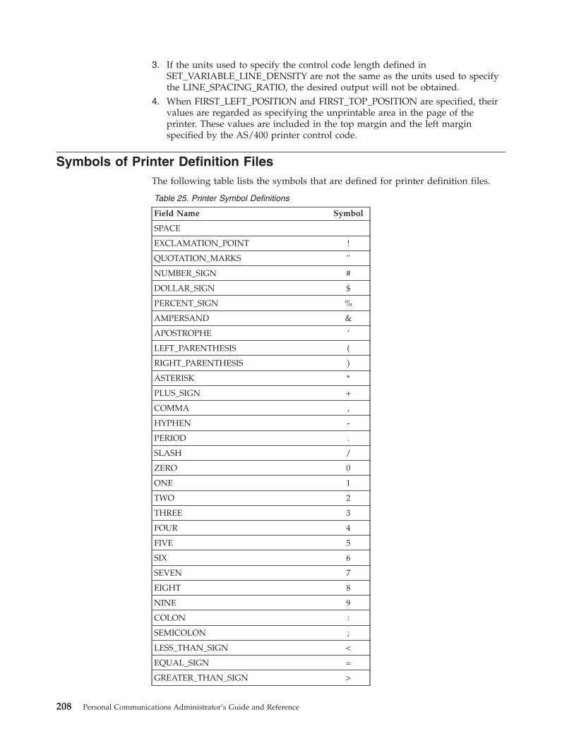
3. If the units used to specify the control code length defined inSET_VARIABLE_LINE_DENSITY are not the same as the units used to specifythe LINE_SPACING_RATIO, the desired output will not be obtained.
4. When FIRST_LEFT_POSITION and FIRST_TOP_POSITION are specified, theirvalues are regarded as specifying the unprintable area in the page of theprinter. These values are included in the top margin and the left marginspecified by the AS/400 printer control code.
Symbols of Printer Definition FilesThe following table lists the symbols that are defined for printer definition files.
Table 25. Printer Symbol Definitions
Field Name Symbol
SPACE
EXCLAMATION_POINT !
QUOTATION_MARKS "
NUMBER_SIGN #
DOLLAR_SIGN $
PERCENT_SIGN %
AMPERSAND &
APOSTROPHE ’
LEFT_PARENTHESIS (
RIGHT_PARENTHESIS )
ASTERISK *
PLUS_SIGN +
COMMA ,
HYPHEN -
PERIOD .
SLASH /
ZERO 0
ONE 1
TWO 2
THREE 3
FOUR 4
FIVE 5
SIX 6
SEVEN 7
EIGHT 8
NINE 9
COLON :
SEMICOLON ;
LESS_THAN_SIGN <
EQUAL_SIGN =
GREATER_THAN_SIGN >
208 Personal Communications Administrator’s Guide and Reference

Table 25. Printer Symbol Definitions (continued)
Field Name Symbol
QUESTION_MARK ?
AT_SIGN @
A_CAPITAL A
B_CAPITAL B
C_CAPITAL C
D_CAPITAL D
E_CAPITAL E
F_CAPITAL F
G_CAPITAL G
H_CAPITAL H
I_CAPITAL I
J_CAPITAL J
K_CAPITAL K
L_CAPITAL L
M_CAPITAL M
N_CAPITAL N
O_CAPITAL O
P_CAPITAL P
Q_CAPITAL Q
R_CAPITAL R
S_CAPITAL S
T_CAPITAL T
U_CAPITAL U
V_CAPITAL V
W_CAPITAL W
X_CAPITAL X
Y_CAPITAL Y
Z_CAPITAL Z
LEFT_BRACKET [
BACKSLASH \
RIGHT_BRACKET ]
CIRCUMFLEX_ACCENT ^
UNDERLINE _
GRAVE_ACCENT
A_SMALL a
B_SMALL b
C_SMALL c
D_SMALL d
E_SMALL e
F_SMALL f
Chapter 18. Building a Printer Definition Table (PDT) for PC400 209

Table 25. Printer Symbol Definitions (continued)
Field Name Symbol
G_SMALL g
H_SMALL h
I_SMALL i
J_SMALL j
K_SMALL k
L_SMALL l
M_SMALL m
N_SMALL n
O_SMALL o
P_SMALL p
Q_SMALL q
R_SMALL r
S_SMALL s
T_SMALL t
U_SMALL u
V_SMALL v
W_SMALL w
X_SMALL x
Y_SMALL y
Z_SMALL z
LEFT_BRACE {
VERTICAL_BAR │
RIGHT_BRACE }
TILDE_ACCENT
C_CEDILLA_CAPITAL Ç
U_DIAERESIS_SMALL ü
E_ACUTE_SMALL é
A_CIRCUMFLEX_SMALL â
A_DIAERESIS_SMALL ä
A_GRAVE_SMALL à
A_OVERCIRCLE_SMALL å
C_CEDILLA_SMALL ç
E_CIRCUMFLEX_SMALL ê
E_DIAERESIS_SMALL ë
E_GRAVE_SMALL è
I_DIAERESIS_SMALL ï
I_CIRCUMFLEX_SMALL î
I_GRAVE_SMALL ì
A_DIAERESIS_CAPITAL Ä
A_OVERCIRCLE_CAPITAL Å
210 Personal Communications Administrator’s Guide and Reference
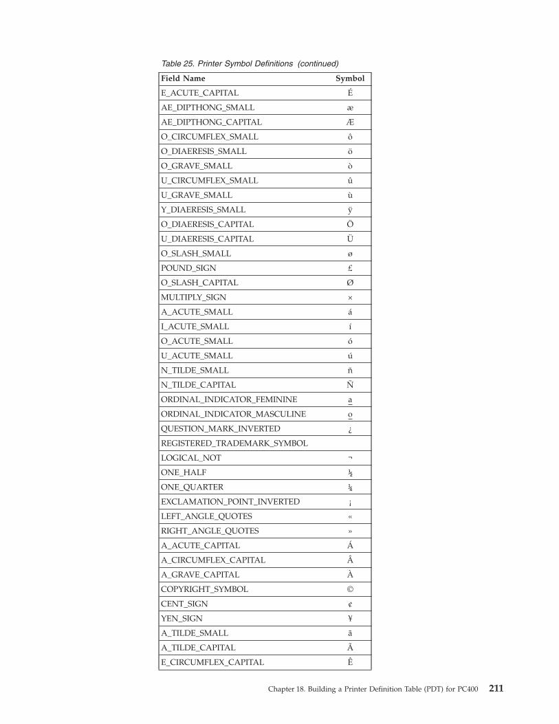
Table 25. Printer Symbol Definitions (continued)
Field Name Symbol
E_ACUTE_CAPITAL É
AE_DIPTHONG_SMALL æ
AE_DIPTHONG_CAPITAL Æ
O_CIRCUMFLEX_SMALL ô
O_DIAERESIS_SMALL ö
O_GRAVE_SMALL ò
U_CIRCUMFLEX_SMALL û
U_GRAVE_SMALL ù
Y_DIAERESIS_SMALL ÿ
O_DIAERESIS_CAPITAL Ö
U_DIAERESIS_CAPITAL Ü
O_SLASH_SMALL ø
POUND_SIGN £
O_SLASH_CAPITAL Ø
MULTIPLY_SIGN ×
A_ACUTE_SMALL á
I_ACUTE_SMALL í
O_ACUTE_SMALL ó
U_ACUTE_SMALL ú
N_TILDE_SMALL ñ
N_TILDE_CAPITAL Ñ
ORDINAL_INDICATOR_FEMININE a
ORDINAL_INDICATOR_MASCULINE o
QUESTION_MARK_INVERTED ¿
REGISTERED_TRADEMARK_SYMBOL
LOGICAL_NOT ¬
ONE_HALF ½
ONE_QUARTER ¼
EXCLAMATION_POINT_INVERTED ¡
LEFT_ANGLE_QUOTES «
RIGHT_ANGLE_QUOTES »
A_ACUTE_CAPITAL Á
A_CIRCUMFLEX_CAPITAL Â
A_GRAVE_CAPITAL À
COPYRIGHT_SYMBOL ©
CENT_SIGN ¢
YEN_SIGN ¥
A_TILDE_SMALL ã
A_TILDE_CAPITAL Ã
E_CIRCUMFLEX_CAPITAL Ê
Chapter 18. Building a Printer Definition Table (PDT) for PC400 211

Table 25. Printer Symbol Definitions (continued)
Field Name Symbol
E_DIAERESIS_CAPITAL Ë
I_ACUTE_CAPITAL Í
I_CIRCUMFLEX_CAPITAL Î
I_DIAERESIS_CAPITAL Ï
VERTICAL_LINE_BROKEN ¦
I_GRAVE_CAPITAL Ì
O_ACUTE_CAPITAL Ó
O_CIRCUMFLEX_CAPITAL Ô
O_GRAVE_CAPITAL Ò
O_TILDE_SMALL õ
O_TILDE_CAPITAL Õ
MICRO_SYMBOL µ
U_ACUTE_CAPITAL Ú
U_CIRCUMFLEX_CAPITAL Û
U_GRAVE_CAPITAL Ù
ACUTE_ACCENT u
SYLLABLE_HYPHEN -
PLUS_OR_MINUS_SIGN ±
THREE_QUARTERS ¾
PARAGRAPH_SYMBOL ¶
SECTION_SYMBOL §
DIVIDE_SIGN ÷
DEGREE_SYMBOL °
ONE_SUPERSCRIPT ¹
THREE_SUPERSCRIPT ³
TWO_SUPERSCRIPT ²
REQUIRED_SPACE
INTERNATIONAL_CURRENCY_SYMBOL ¤
ETH_ICELANDIC_SMALL ð
ETH_ICELANDIC_CAPITAL Ð
SHARP_S_SMALL ß
THORN_ICELANDIC_SMALL þ
THORN_ICELANDIC_CAPITAL Þ
Y_ACUTE_SMALL ý
Y_ACUTE_CAPITAL Ý
OVERLINE ‾
CEDILLA q
DIAERESIS ..
MIDDLE_DOT_ACCENT ·
212 Personal Communications Administrator’s Guide and Reference

Using Printer Control CodesThis section explains the SNA Character String (SCS) control codes, or Final FormText: Document Content Architecture (FFT DCA).
For details of AS/400 printer control codes, refer to AS/400 Guide to Programmingfor Printing.
Printer Control Code FormatSome printer control codes perform single, specific functions by themselves, whileothers perform multiple functions according to the parameters specified after thecontrol code.
A printer control code with parameters has the following format:
Control Code Count Parameter 1 Parameter 2...
1 or 2 bytes 1 byte 1 or 2 bytes 1 or 2 bytes
A count consists of 1 byte, and indicates the length of the parameters (includingthe count) after the control code, in bytes. For example, a count and two 1-byteparameters is shown as X'03', because the count itself is included. Some controlcodes, such as the Printing Position (PP) control code, do not have counts.
A parameter can be 1 or 2 bytes in length. The number of bytes depends on thecontrol codes. Not all control codes have parameters.
Note: In this manual, counts and parameters that are actually processed in binaryare all expressed in hexadecimal (0–F) to improve readability.
Parameter Definition of Printer Control CodesSome printer control codes require that parameters be specified. Pay particularattention when defining a parameter because how this is done depends on theparameter type. If the definition method for another type is used, the desiredoutput will not be obtained.
The following table lists printer control code parameter types and their meanings:
Table 26. Printer Control Code Parameter Types
Parameter Type Meaning
byte-value One-byte parameter.
byte-values Multibyte parameter.Used if operands are fixed.
word-value(HL) One-word parameter (higher and lower bytes).
word-value(LH) One-word parameter (lower and higher bytes).
length(HL)-values Multibyte parameter requiring operands.An operand consists of a higher and lower byte.Used if operands are variable.
length(LH)-values Multibyte parameter requiring operands.An operand consists of a lower and higher byte.Used if operands are variable.
length(HL)-images Image data requiring operands.An operand consists of a higher and lower byte.
Chapter 18. Building a Printer Definition Table (PDT) for PC400 213
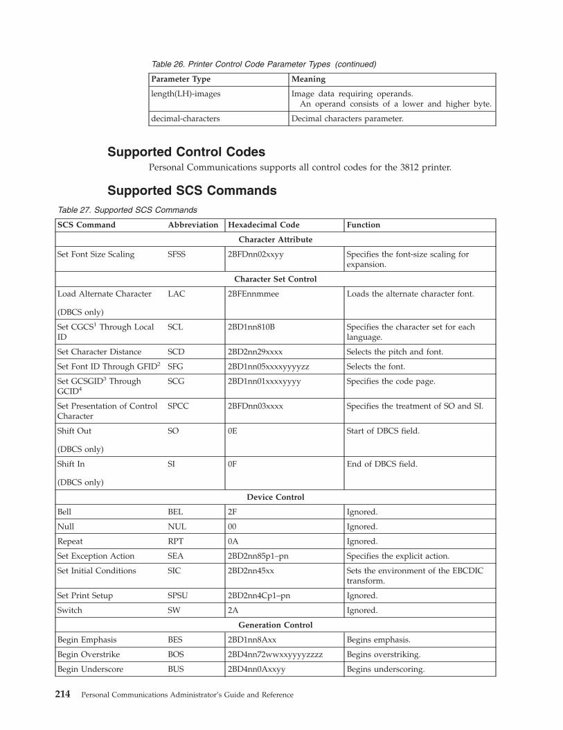
Table 26. Printer Control Code Parameter Types (continued)
Parameter Type Meaning
length(LH)-images Image data requiring operands.An operand consists of a lower and higher byte.
decimal-characters Decimal characters parameter.
Supported Control CodesPersonal Communications supports all control codes for the 3812 printer.
Supported SCS CommandsTable 27. Supported SCS Commands
SCS Command Abbreviation Hexadecimal Code Function
Character Attribute
Set Font Size Scaling SFSS 2BFDnn02xxyy Specifies the font-size scaling forexpansion.
Character Set Control
Load Alternate Character
(DBCS only)
LAC 2BFEnnmmee Loads the alternate character font.
Set CGCS1 Through LocalID
SCL 2BD1nn810B Specifies the character set for eachlanguage.
Set Character Distance SCD 2BD2nn29xxxx Selects the pitch and font.
Set Font ID Through GFID2 SFG 2BD1nn05xxxxyyyyzz Selects the font.
Set GCSGID3 ThroughGCID4
SCG 2BD1nn01xxxxyyyy Specifies the code page.
Set Presentation of ControlCharacter
SPCC 2BFDnn03xxxx Specifies the treatment of SO and SI.
Shift Out
(DBCS only)
SO 0E Start of DBCS field.
Shift In
(DBCS only)
SI 0F End of DBCS field.
Device Control
Bell BEL 2F Ignored.
Null NUL 00 Ignored.
Repeat RPT 0A Ignored.
Set Exception Action SEA 2BD2nn85p1–pn Specifies the explicit action.
Set Initial Conditions SIC 2BD2nn45xx Sets the environment of the EBCDICtransform.
Set Print Setup SPSU 2BD2nn4Cp1–pn Ignored.
Switch SW 2A Ignored.
Generation Control
Begin Emphasis BES 2BD1nn8Axx Begins emphasis.
Begin Overstrike BOS 2BD4nn72wwxxyyyyzzzz Begins overstriking.
Begin Underscore BUS 2BD4nn0Axxyy Begins underscoring.
214 Personal Communications Administrator’s Guide and Reference
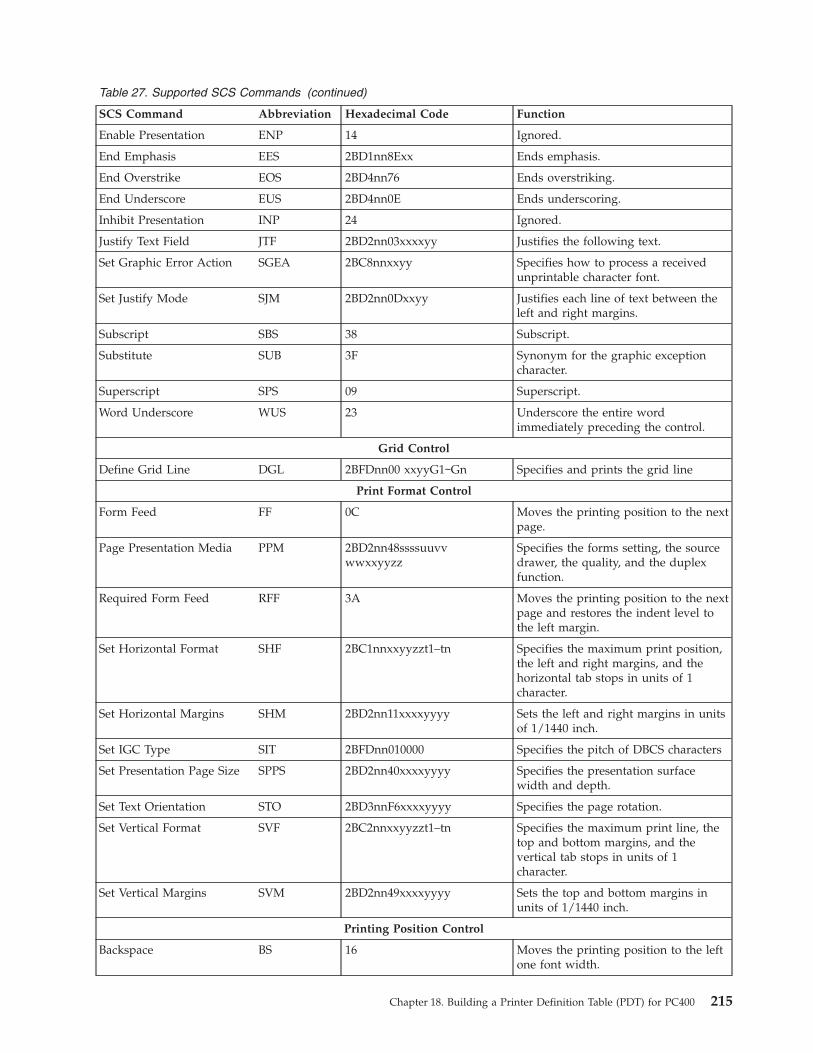
Table 27. Supported SCS Commands (continued)
SCS Command Abbreviation Hexadecimal Code Function
Enable Presentation ENP 14 Ignored.
End Emphasis EES 2BD1nn8Exx Ends emphasis.
End Overstrike EOS 2BD4nn76 Ends overstriking.
End Underscore EUS 2BD4nn0E Ends underscoring.
Inhibit Presentation INP 24 Ignored.
Justify Text Field JTF 2BD2nn03xxxxyy Justifies the following text.
Set Graphic Error Action SGEA 2BC8nnxxyy Specifies how to process a receivedunprintable character font.
Set Justify Mode SJM 2BD2nn0Dxxyy Justifies each line of text between theleft and right margins.
Subscript SBS 38 Subscript.
Substitute SUB 3F Synonym for the graphic exceptioncharacter.
Superscript SPS 09 Superscript.
Word Underscore WUS 23 Underscore the entire wordimmediately preceding the control.
Grid Control
Define Grid Line DGL 2BFDnn00 xxyyG1∼Gn Specifies and prints the grid line
Print Format Control
Form Feed FF 0C Moves the printing position to the nextpage.
Page Presentation Media PPM 2BD2nn48ssssuuvvwwxxyyzz
Specifies the forms setting, the sourcedrawer, the quality, and the duplexfunction.
Required Form Feed RFF 3A Moves the printing position to the nextpage and restores the indent level tothe left margin.
Set Horizontal Format SHF 2BC1nnxxyyzzt1–tn Specifies the maximum print position,the left and right margins, and thehorizontal tab stops in units of 1character.
Set Horizontal Margins SHM 2BD2nn11xxxxyyyy Sets the left and right margins in unitsof 1/1440 inch.
Set IGC Type SIT 2BFDnn010000 Specifies the pitch of DBCS characters
Set Presentation Page Size SPPS 2BD2nn40xxxxyyyy Specifies the presentation surfacewidth and depth.
Set Text Orientation STO 2BD3nnF6xxxxyyyy Specifies the page rotation.
Set Vertical Format SVF 2BC2nnxxyyzzt1–tn Specifies the maximum print line, thetop and bottom margins, and thevertical tab stops in units of 1character.
Set Vertical Margins SVM 2BD2nn49xxxxyyyy Sets the top and bottom margins inunits of 1/1440 inch.
Printing Position Control
Backspace BS 16 Moves the printing position to the leftone font width.
Chapter 18. Building a Printer Definition Table (PDT) for PC400 215
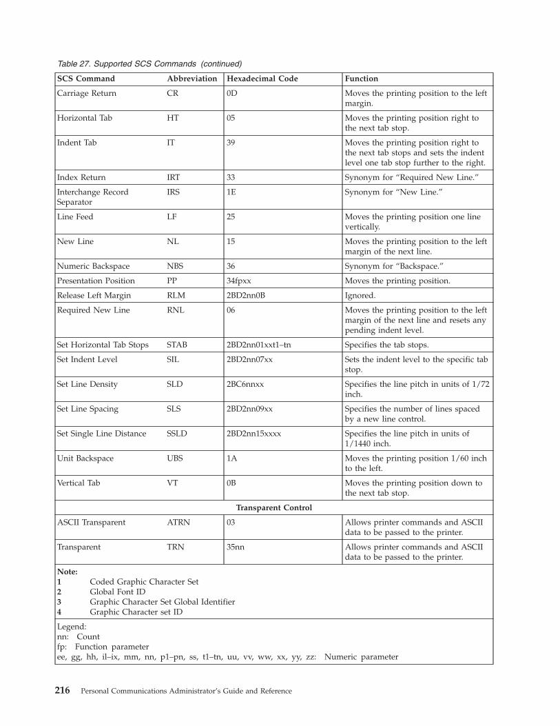
Table 27. Supported SCS Commands (continued)
SCS Command Abbreviation Hexadecimal Code Function
Carriage Return CR 0D Moves the printing position to the leftmargin.
Horizontal Tab HT 05 Moves the printing position right tothe next tab stop.
Indent Tab IT 39 Moves the printing position right tothe next tab stops and sets the indentlevel one tab stop further to the right.
Index Return IRT 33 Synonym for “Required New Line.”
Interchange RecordSeparator
IRS 1E Synonym for “New Line.”
Line Feed LF 25 Moves the printing position one linevertically.
New Line NL 15 Moves the printing position to the leftmargin of the next line.
Numeric Backspace NBS 36 Synonym for “Backspace.”
Presentation Position PP 34fpxx Moves the printing position.
Release Left Margin RLM 2BD2nn0B Ignored.
Required New Line RNL 06 Moves the printing position to the leftmargin of the next line and resets anypending indent level.
Set Horizontal Tab Stops STAB 2BD2nn01xxt1–tn Specifies the tab stops.
Set Indent Level SIL 2BD2nn07xx Sets the indent level to the specific tabstop.
Set Line Density SLD 2BC6nnxx Specifies the line pitch in units of 1/72inch.
Set Line Spacing SLS 2BD2nn09xx Specifies the number of lines spacedby a new line control.
Set Single Line Distance SSLD 2BD2nn15xxxx Specifies the line pitch in units of1/1440 inch.
Unit Backspace UBS 1A Moves the printing position 1/60 inchto the left.
Vertical Tab VT 0B Moves the printing position down tothe next tab stop.
Transparent Control
ASCII Transparent ATRN 03 Allows printer commands and ASCIIdata to be passed to the printer.
Transparent TRN 35nn Allows printer commands and ASCIIdata to be passed to the printer.
Note:1 Coded Graphic Character Set2 Global Font ID3 Graphic Character Set Global Identifier4 Graphic Character set ID
Legend:nn: Countfp: Function parameteree, gg, hh, il–ix, mm, nn, p1–pn, ss, t1–tn, uu, vv, ww, xx, yy, zz: Numeric parameter
216 Personal Communications Administrator’s Guide and Reference

Programming NotesThis section briefly explains how a printer reacts if a partial control code isreceived, or if an incomplete control code is sent.
If the transmission of a control code is interrupted, the printer waits for theremaining part of the code. If the data stream (the series of data units and controlcodes) sent after the interruption is consistent with the data stream sent before theinterruption, (that is, if one complete printer control code is restored by chaining),the control code is processed as is.
If the two parts of the data stream are inconsistent, an error occurs. A negativeresponse to an “Invalid Printer Parameter” is sent to the host system, or treated asa no-op (no operation; ignored because of a meaningless code). Detailedinformation is not sent to the host system if an error occurs in a control code. Afterprogramming, the data stream must be checked thoroughly by repeating theprinting test.
Restrictions and Notes for AS/400 Printer Commands andPrinter Setup
This section provides supplementary notes and explains restrictions for printing.
Printer Control CodesTable 28. Printer Control Codes
Printer Control Code If Use PDT file is Selected:If a Windows Printer Driveris Used:
SCD — Set the CharacterDensity
Select the GFID for the valid character distance (CD)parameter as shown in Table 29 on page 218.
If the specified font is notsupported, a substitution isprovided. For example, when15 CPI font is specified butthe font is not supported, thesupported 17 CPI font issubstituted.
See “How to DeterminePC400 Font” on page 218.
SFG — Set Font ID throughGFID
Recognizable GFIDs are restricted. (See “Field Names ofPrinter Definition Files” on page 201.) If the specified GFIDis not supported and it is out of the range from 154 through200, the closest font width from the fonts shown in Table 30on page 218 is substituted.
If the specified GFID is not supported and it is between 154and 200, the following font is substituted: Font name:Document; GFID value:175.
See “How to DeterminePC400 Font” on page 218.
BUS — Begin Underscore The selected font might notsupport the underscore.
BES — Begin Emphasis The selected font might notsupport the emphasis.
Chapter 18. Building a Printer Definition Table (PDT) for PC400 217

Table 28. Printer Control Codes (continued)
Printer Control Code If Use PDT file is Selected:If a Windows Printer Driveris Used:
STO — Set Text Orientation The page orientation can bechanged to portrait orlandscape. The direction,which is up, down, left, orright on the paper, dependson the Microsoft Windowsprinter driver. If the pageorientation is changed, thecurrent paper is ejected.
PPM — Page PresentationMedia
The following parameters are supported for PDTs in DBCSmode:v Forms Control (FC)v Source Drawer (SD)v Duplex (DX)
Other parameters are ignored.
Table 29. SCD Parameter Values
CD Parameter Character Pitch (normal) GFID Value (COR)
000A 10 CPI 13 CPI 204000B Proportional 13 CPI 175000C 12 CPI 15 CPI 86000F 15 CPI 20 CPI 23000FF 10 CPI 13 CPI 204
The following table lists only the most commonly used GFIDs. See Table 31 onpage 219 for the complete list.
Table 30. Commonly Used SFG GFID Values
Font Name GFID value
Courier Bold 5 245Courier 10 11Prestige Elite 12 86Gothic-text 13 204Gothic-text 15 230Courier 17 252Gothic-text 20 281Gothic-text 27 290
When you use the Windows printer driver, the spooler must be on.
How to Determine PC400 FontWhen a print job is created on AS/400, a certain font, identified by font ID (GFID),is associated with it. Such a font can be specified by the following parameters:v Font familyv Pitch and familyv Character setv Width
218 Personal Communications Administrator’s Guide and Reference
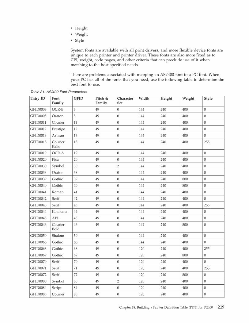
v Heightv Weightv Style
System fonts are available with all print drivers, and more flexible device fonts areunique to each printer and printer driver. These fonts are also more fixed as toCPI, weight, code pages, and other criteria that can preclude use of it whenmatching to the host specified needs.
There are problems associated with mapping an AS/400 font to a PC font. Whenyour PC has all of the fonts that you need, use the following table to determine thebest font to use.
Table 31. AS/400 Font Parameters
Entry ID FontFamily
GFID Pitch &Family
CharacterSet
Width Height Weight Style
GFID0003 OCR-B 3 49 0 144 240 400 0
GFID0005 Orator 5 49 0 144 240 400 0
GFID0011 Courier 11 49 0 144 240 400 0
GFID0012 Prestige 12 49 0 144 240 400 0
GFID0013 Artisan 13 49 0 144 240 400 0
GFID0018 CourierItalic
18 49 0 144 240 400 255
GFID0019 OCR-A 19 49 0 144 240 400 0
GFID0020 Pica 20 49 0 144 240 400 0
GFID0030 Symbol 30 49 2 144 240 400 0
GFID0038 Orator 38 49 0 144 240 400 0
GFID0039 Gothic 39 49 0 144 240 800 0
GFID0040 Gothic 40 49 0 144 240 800 0
GFID0041 Roman 41 49 0 144 240 400 0
GFID0042 Serif 42 49 0 144 240 400 0
GFID0043 Serif 43 49 0 144 240 400 255
GFID0044 Katakana 44 49 0 144 240 400 0
GFID0045 APL 45 49 0 144 240 400 0
GFID0046 CourierBold
46 49 0 144 240 800 0
GFID0050 Shalom 50 49 0 144 240 400 0
GFID0066 Gothic 66 49 0 144 240 400 0
GFID0068 Gothic 68 49 0 120 240 400 255
GFID0069 Gothic 69 49 0 120 240 800 0
GFID0070 Serif 70 49 0 120 240 400 0
GFID0071 Serif 71 49 0 120 240 400 255
GFID0072 Serif 72 49 0 120 240 800 0
GFID0080 Symbol 80 49 2 120 240 400 0
GFID0084 Script 84 49 0 120 240 400 0
GFID0085 Courier 85 49 0 120 240 400 0
Chapter 18. Building a Printer Definition Table (PDT) for PC400 219

Table 31. AS/400 Font Parameters (continued)
Entry ID FontFamily
GFID Pitch &Family
CharacterSet
Width Height Weight Style
GFID0086 Prestige 86 49 0 120 240 400 0
GFID0087 Letter-Gothic
87 49 0 120 240 400 0
GFID0091 Light 91 49 0 120 240 400 255
GFID0107 Courier 107 49 0 120 240 400 0
GFID0110 Letter-Gothic
110 49 0 120 240 800 0
GFID0111 Prestige 111 49 0 120 240 800 0
GFID0112 Prestige 112 49 0 120 240 400 255
GFID0115 Symbol 115 49 2 120 240 400 0
GFID0155 Boldface 155 18 0 120 240 400 0
GFID0158 Document 158 18 0 120 240 400 0
GFID0159 Boldface 159 18 0 120 240 800 0
GFID0160 Essay 160 34 0 120 240 800 0
GFID0162 Essay 162 34 0 120 240 800 255
GFID0163 Essay 163 34 0 120 240 800 0
GFID0168 Barak 168 18 0 120 240 400 0
GFID0173 Essay 173 34 0 120 240 400 0
GFID0175 Document 175 18 0 120 240 400 0
GFID0176 Boldface 176 18 0 120 240 800 0
GFID0177 Boldface 177 18 0 120 240 800 255
GFID0193 Symbol 193 49 2 120 240 400 0
GFID0198 Symbol 198 49 2 144 240 400 0
GFID0204 Gothic 204 49 0 108 210 400 0
GFID0221 Prestige 221 49 0 96 210 400 0
GFID0222 Gothic 222 49 0 96 210 400 0
GFID0223 Courier 223 49 0 96 210 400 0
GFID0225 Symbol 225 49 2 96 240 400 0
GFID0229 Serif 229 49 0 96 210 400 0
GFID0230 Gothic 230 49 0 96 210 400 0
GFID0245 CourierBold
245 49 0 288 240 800 0
GFID0252 Courier 252 49 0 84 240 400 0
GFID0253 CourierBold
253 49 0 84 240 800 0
GFID0254 Courier 254 49 0 84 120 400 0
GFID0280 APL 280 49 0 72 120 400 0
GFID0281 Gothic 281 49 0 72 120 400 0
GFID0290 Gothic 290 49 0 54 120 400 0
GFID0751 Sonoran-serif
751 18 0 54 162 400 0
220 Personal Communications Administrator’s Guide and Reference
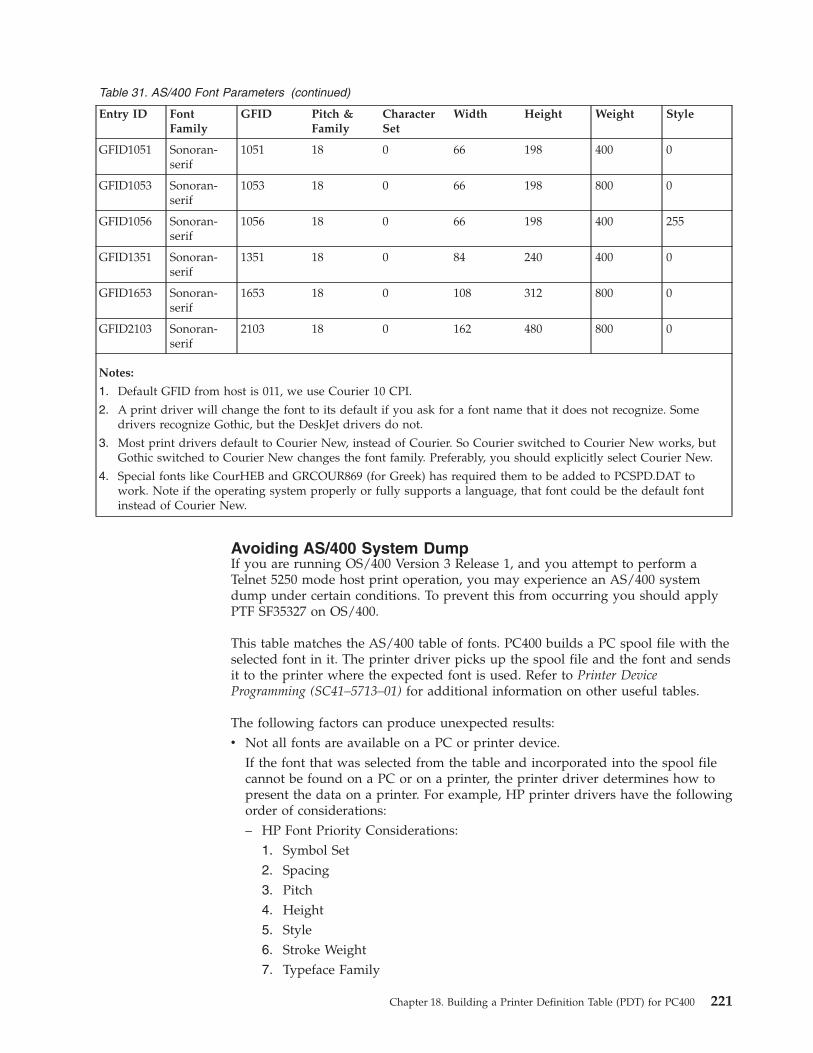
Table 31. AS/400 Font Parameters (continued)
Entry ID FontFamily
GFID Pitch &Family
CharacterSet
Width Height Weight Style
GFID1051 Sonoran-serif
1051 18 0 66 198 400 0
GFID1053 Sonoran-serif
1053 18 0 66 198 800 0
GFID1056 Sonoran-serif
1056 18 0 66 198 400 255
GFID1351 Sonoran-serif
1351 18 0 84 240 400 0
GFID1653 Sonoran-serif
1653 18 0 108 312 800 0
GFID2103 Sonoran-serif
2103 18 0 162 480 800 0
Notes:
1. Default GFID from host is 011, we use Courier 10 CPI.
2. A print driver will change the font to its default if you ask for a font name that it does not recognize. Somedrivers recognize Gothic, but the DeskJet drivers do not.
3. Most print drivers default to Courier New, instead of Courier. So Courier switched to Courier New works, butGothic switched to Courier New changes the font family. Preferably, you should explicitly select Courier New.
4. Special fonts like CourHEB and GRCOUR869 (for Greek) has required them to be added to PCSPD.DAT towork. Note if the operating system properly or fully supports a language, that font could be the default fontinstead of Courier New.
Avoiding AS/400 System DumpIf you are running OS/400 Version 3 Release 1, and you attempt to perform aTelnet 5250 mode host print operation, you may experience an AS/400 systemdump under certain conditions. To prevent this from occurring you should applyPTF SF35327 on OS/400.
This table matches the AS/400 table of fonts. PC400 builds a PC spool file with theselected font in it. The printer driver picks up the spool file and the font and sendsit to the printer where the expected font is used. Refer to Printer DeviceProgramming (SC41–5713–01) for additional information on other useful tables.
The following factors can produce unexpected results:v Not all fonts are available on a PC or printer device.
If the font that was selected from the table and incorporated into the spool filecannot be found on a PC or on a printer, the printer driver determines how topresent the data on a printer. For example, HP printer drivers have the followingorder of considerations:– HP Font Priority Considerations:
1. Symbol Set2. Spacing3. Pitch4. Height5. Style6. Stroke Weight7. Typeface Family
Chapter 18. Building a Printer Definition Table (PDT) for PC400 221
8. Resolution9. Orientation
– Location: printer ROM, SIMM module ROM, cartridge ROM, printer RAMPriority of locations:1. Soft font (lowest ID first)2. Cartridge Font3. SIMM Font4. Internal Font
– 600 dpi has priority over 300 dpi
To avoid this uncertainty, it is recommended that you update the table so thatonly the fonts that are available in the given environment are used.
v NLSThe AS/400 font has NLS characters in it, which are not part of a correspondingPC font. The IBM-supplied table does not support character sets other thanANSI, although it provides a field for them. In this case, PC400 builds a PCspool file with a font that doesn’t recognize NLS.To fix the problem, it is recommended that you either change the font names inthe table to the NLS enabled on a PC/printer, or if the font has the same nameas the one in the table, update a Character Set value.
v After you decide to scale a printout which may be a result of CORig orBesFitting, you usually decrease the distance horizontally as well as verticallybetween characters. This can result in overlapping. PC400 attempts to adjust thegiven character size to a new one. A problem may occur when a font defined inthe table is not a scalable font. Like GFID011, the most heavily used AS/400 fontis mapped to Courier. Courier is a non-scalable font which has only a limitednumber of character box sizes. To avoid possible problems it is recommendedthat you use Courier New instead, which is a scalable TTF font.
PFT Migration UtilityThe PFT migration utility converts the printer function table (PFT) for the PCSupport/400 workstation feature to a printer definition file (PDF) for PC400.
This section describes the operator interface of the PFT migration utility.
For details of PFT, refer to AS/400 PC Support: DOS and OS/2 Technical ReferenceSC21-8091.
Using the PFT Migration UtilityThe file name of the PFT Migration Utility program is PCSPFC.EXE. It is aWindows application, and you can execute it by doing the following:1. Double-click the program name using the Windows Explorer utility.2. Specify the program name (and parameters) in the Windows Run utility as
follows:
If no parameter is specified, PCSPFC.EXE displays the Convert PFT to PDFdialog box.
PCSPFC [ [drive:] [path] PFT-file-name[.extension] ]
222 Personal Communications Administrator’s Guide and Reference

If you omit a drive name and a directory name, PCSPFC.EXE uses thecurrent drive and the current directory. If you omit an extension,PCSPFC.EXE adds .PFT to the PFT file name.
3. When you execute the PFT Migration Utility, the Convert PFT to PDF dialogbox appears. On the Convert PFT to PDF dialog box, select a PFT file from thelist box or type a specific PFT file name, and click OK. The PFT MigrationUtility starts the conversion and displays the PFT File Converter dialog box toshow the conversion status.
After the conversion, if you click Save List on the PFT File Converter dialog box,conversion messages in the dialog box are saved into a list file. The list file iscreated in the same directory and with the same name as the PFT file, except theextension. The extension of the list file is .LS2.
If the conversion was completed successfully, you can click Convert PDF to PDTfrom the PFT File Converter dialog box to convert the PDF file to a PDT file. Youcan also create a PDT file by selecting Printer Setup from the File pull-down menuas explained in “Using the Printer Definition Table (PDT) File” on page 185.
Migration ConsiderationsWhen the base PDF file already exists, the converted PDF fields are appended tothe end of the base PDF file. The name of the base PDF file is decided as follows:
Table 32. PDF File Name
PFT File Name Base PDF File Name
xxxxxxxx.PFT xxxxxxxx.PDF
xxxxx.MNL MNLxxxxx.PDF
zzzxxxxx.MNL* zzzxxxxx.PDF*
: * “zzz” is not “IBM”.
Even if the same fields are already defined in the PDF file, the appended fields areeffective because the last definition is always effective in a PDF file.
If the base PDF file does not exist in the directory, the PFT Migration Utilitycreatesa new PDF file that has only the converted fields from the PFT file. In this case,you should append this file to an appropriate base file manually, because the fieldsconverted from the PFT file do not cover all of the necessary PDF fields.
Therefore, it is recommended that you prepare both the PFT file and its base PDFfile in the same directory before the conversion.
Details of MigrationThis section describes how the PFT Migration Utility migrates the printer functiontable (PFT) to the printer definition file (PDF).
Migration from the Printer Function TableThe following table shows the target fields of the PDF for the data in the PFT.
Table 33. Migration from the Printer Function Table to the Printer Definition File
PFT Field Name
PDF Field Name
Description
INITIALIZATION AND RESET
Chapter 18. Building a Printer Definition Table (PDT) for PC400 223

Table 33. Migration from the Printer Function Table to the Printer Definition File (continued)
PFT Field Name
PDF Field Name
Description
Initialization
Initialization START_JOB=
When the data is defined in the Initialization field of PFT, thedata is appended to the string START_JOB=.
Filename
Filename None
This field is ignored.
Reset
Reset END_JOB=
When the data is defined in the Reset field of PFT, the data isappended to the string END_JOB=.
VERTICAL LINE SPACING
6 lines per inch
6 lines per inch SET_6_LINES_PER_INCH=
When the data is defined in the 6 lines per inch field of PFT, thedata is appended to the string SET_6_LINES_PER_INCH=.
8 lines per inch
8 lines per inch SET_8_LINES_PER_INCH=
When the data is defined in the 8 lines per inch field of PFT, thedata is appended to the string SET_8_LINES_PER_INCH=.
Variable line spacing
Control Sequence SET_VARIABLE_DENSITY=
When the data is defined in the control sequence field of the PFTfor the variable line spacing, the data is appended to the stringSET_VARIABLE_DENSITY=. The parameter n in the controlsequence is replaced with the PDF parameter type.
Maximum None
This field is ignored.
Offset None
This field is ignored.
X/Y LINE_SPACING_RATIO=
When the data is defined in the X/Y field of the PFT for thevariable line spacing, the value Y/X is appended to the stringLINE_SPACING_RATIO= as three-digit or four-digit numbers toindicate the decimal number. For example, when Y/X is 72, the072 is appended to the string LINE_SPACING_RATIO= andLINE_SPACING_RATIO=072 is written to the output file. When thevalue is greater than 255, the four-digit number is migrated.When the value is less than 255, the three-digit number ismigrated.
Indexing Functions
224 Personal Communications Administrator’s Guide and Reference

Table 33. Migration from the Printer Function Table to the Printer Definition File (continued)
PFT Field Name
PDF Field Name
Description
Begin Superscript START_SUPERSCRIPT=
When the data is defined in the Begin Superscript field and EndSuperscript field of the PFT for the indexing functions, the datais appended to the string START_SUPERSCRIPT=. If the data forthe End Superscript is not defined, the data for the BeginSuperscript is ignored.
End Superscript END_SUPERSCRIPT=
When the data is defined in the End Superscript field and BeginSuperscript field of the PFT for the indexing functions, the datais appended to the string END_SUPERSCRIPT=. If the data forthe Begin Superscript is not defined, the data for the EndSuperscript is ignored.
Begin Subscript START_SUBSCRIPT=
When the data is defined in the Begin Subscript field and EndSubscript field of the PFT for the indexing functions, the data isappended to the string START_SUBSCRIPT=. If the data for theEnd Subscript is not defined, the data for the Begin Subscript isignored.
End Subscript END_SUBSCRIPT=
When the data is defined in the End Subscript field and BeginSubscript field of the PFT for the indexing functions, the data isappended to the string END_SUBSCRIPT=. If the data for theBegin Subscript is not defined, the data for the End Subscript isignored.
Reverse 1/2 Index START_SUPERSCRIPT= END_SUBSCRIPT=
The data is appended to the START_SUPERSCRIPT= for all ofthe following conditions:v When the data is not defined in the Begin Superscript field in
the PFT or when the data is not defined in the End Superscriptfield in the PFT.
v When the data is defined in the Reverse 1/2 index andForward 1/2 index field in the PFT.
The data is appended to END_SUBSCRIPT= for all of thefollowing conditions:v When the data is not defined in the Begin Subscript field in
the PFT or when the data is not defined in the End Subscriptfield in the PFT.
v When the data is defined in the Reverse 1/2 index andForward 1/2 index field in the PFT.
Chapter 18. Building a Printer Definition Table (PDT) for PC400 225

Table 33. Migration from the Printer Function Table to the Printer Definition File (continued)
PFT Field Name
PDF Field Name
Description
Forward 1/2 Index END_SUPERSCRIPT= START_SUBSCRIPT=
The data is appended to END_SUPERSCRIPT= for all of thefollowing conditions:v When the data is not defined in Begin Superscript field in the
PFT or when the data is not defined in End Superscript fieldin the PFT.
v When the data is defined in the Reverse 1/2 index andForward 1/2 index field in the PFT.
The data is appended to START_SUBSCRIPT= for all of thefollowing conditions:v When the data is not defined in the Begin Subscript field in
the PFT or when the data is not defined in the End Subscriptfield in the PFT.
v When the data is defined in the Reverse 1/2 index andForward 1/2 index field in the PFT.
Reverse Index None
This field is ignored.
HORIZONTAL LINE SPACING
5 pitch
5 pitch None
This field is ignored.
8.55 pitch
8.55 pitch None
This field is ignored.
10 pitch
10 pitch SET_10_CHARACTERS_PER_INCH=
When the data is defined in the 10 pitch field of the PFT for thehorizontal character spacing, the data is appended to the stringSET_10_CHARACTERS_PER_INCH=.
12 pitch
12 pitch SET_12_CHARACTERS_PER_INCH=
When the data is defined in the 12 pitch field of the PFT for thehorizontal character spacing, the data is appended to the stringSET_12_CHARACTERS_PER_INCH=.
15 pitch
15 pitch SET_15_CHARACTERS_PER_INCH=
When the data is defined in the 15 pitch field of the PFT for thehorizontal character spacing, the data is appended to the stringSET_15_CHARACTERS_PER_INCH=.
17.1 pitch
17.1 pitch SET_17_CHARACTERS_PER_INCH=
When the data is defined in the 17.1 pitch field of the PFT for thehorizontal character spacing, the data is appended to the stringSET_17_CHARACTERS_PER_INCH=.
Horizontal Motion Index
226 Personal Communications Administrator’s Guide and Reference
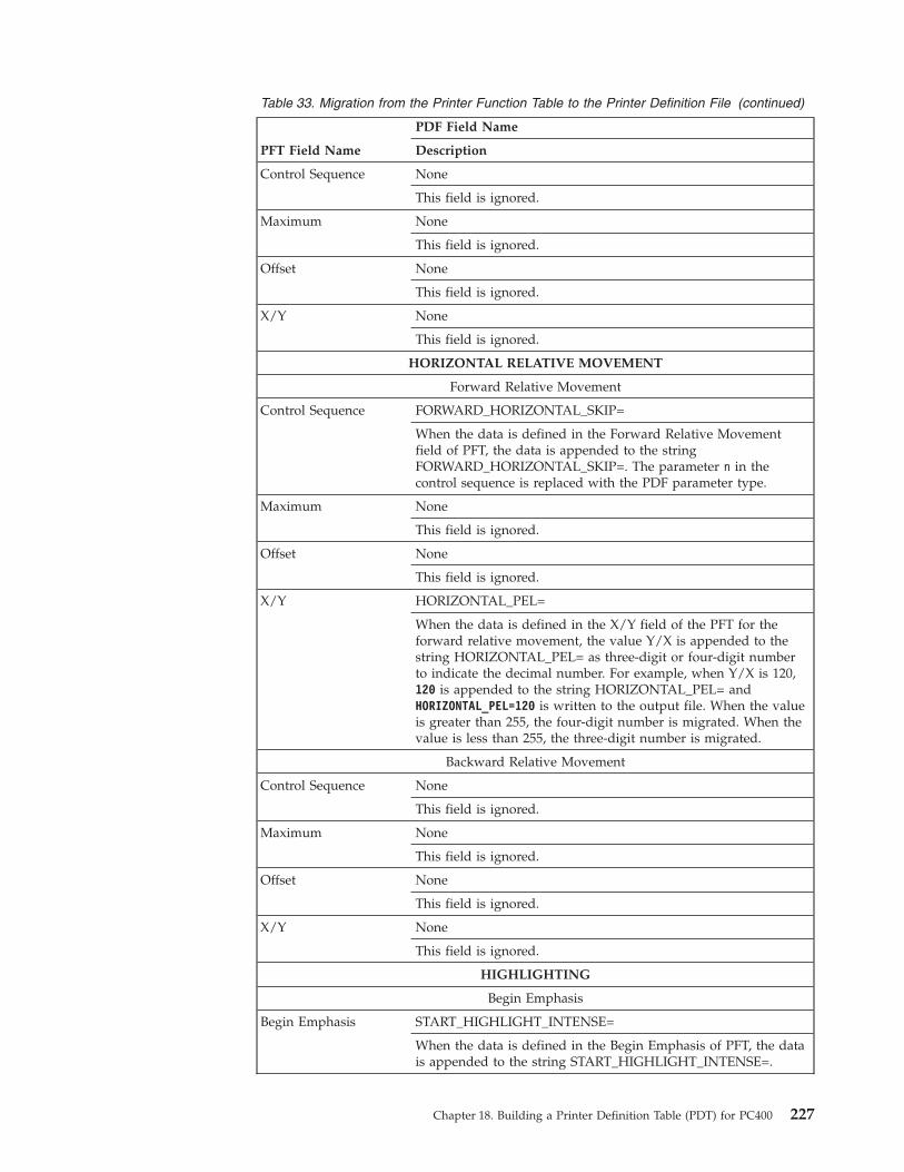
Table 33. Migration from the Printer Function Table to the Printer Definition File (continued)
PFT Field Name
PDF Field Name
Description
Control Sequence None
This field is ignored.
Maximum None
This field is ignored.
Offset None
This field is ignored.
X/Y None
This field is ignored.
HORIZONTAL RELATIVE MOVEMENT
Forward Relative Movement
Control Sequence FORWARD_HORIZONTAL_SKIP=
When the data is defined in the Forward Relative Movementfield of PFT, the data is appended to the stringFORWARD_HORIZONTAL_SKIP=. The parameter n in thecontrol sequence is replaced with the PDF parameter type.
Maximum None
This field is ignored.
Offset None
This field is ignored.
X/Y HORIZONTAL_PEL=
When the data is defined in the X/Y field of the PFT for theforward relative movement, the value Y/X is appended to thestring HORIZONTAL_PEL= as three-digit or four-digit numberto indicate the decimal number. For example, when Y/X is 120,120 is appended to the string HORIZONTAL_PEL= andHORIZONTAL_PEL=120 is written to the output file. When the valueis greater than 255, the four-digit number is migrated. When thevalue is less than 255, the three-digit number is migrated.
Backward Relative Movement
Control Sequence None
This field is ignored.
Maximum None
This field is ignored.
Offset None
This field is ignored.
X/Y None
This field is ignored.
HIGHLIGHTING
Begin Emphasis
Begin Emphasis START_HIGHLIGHT_INTENSE=
When the data is defined in the Begin Emphasis of PFT, the datais appended to the string START_HIGHLIGHT_INTENSE=.
Chapter 18. Building a Printer Definition Table (PDT) for PC400 227

Table 33. Migration from the Printer Function Table to the Printer Definition File (continued)
PFT Field Name
PDF Field Name
Description
End Emphasis
End Emphasis END_HIGHLIGHT_INTENSE=
When the data is defined in the End Emphasis of PFT, the data isappended to the string END_HIGHLIGHT_INTENSE=.
Begin Underline
Begin Underline START_HIGHLIGHT_UNDERLINE=
When the data is defined in the Begin Underline of PFT, the datais appended to the string START_HIGHLIGHT_UNDERLINE=.
End Underline
End Underline END_HIGHLIGHT_UNDERLINE=
When the data is defined in the End Underline of PFT, the datais appended to the string END_HIGHLIGHT_UNDERLINE=.
Begin Quality Print
Begin Quality Print None
This field is ignored.
End Quality Print
End Quality Print None
This field is ignored.
PAPER HANDLING
Bottom Tray Feed
Bottom Tray Feed SELECT_DRAWER2=
If the data is defined in some fields for LANDSCAPE PAPERHANDLING, the PFT Migration Utility assumes that this controlsequence includes the control of the portrait orientation. For this,the PFT Migration Utility divides this control sequence into twoparts and migrates the control sequence for the drawer select andpaper feed. The control sequence of the portrait orientation ismigrated to SET_PORTRAIT_ORIENT=. If no data is defined inany fields for LANDSCAPE PAPER HANDLING, the PFTMigration Utility migrates this control sequence to theSELECT_DRAWER2=. (See “Definition of PAPER HANDLINGMigration” on page 243.)
Top Tray Feed
Top Tray Feed SELECT_DRAWER1=
If the data is defined in some fields for LANDSCAPE PAPERHANDLING, the PFT Migration Utility assumes that this controlsequence includes the control of the portrait orientation. For this,the PFT Migration Utility divides this control sequence into twoparts and migrates the control sequence for the drawer select andpaper feed. The control sequence of the portrait orientation ismigrated to SET_PORTRAIT_ORIENT=. If no data is defined inany fields for LANDSCAPE PAPER HANDLING, the PFTMigration Utility migrates this control sequence toSELECT_DRAWER1=. (See “Definition of PAPER HANDLINGMigration” on page 243.)
Envelope Feed
228 Personal Communications Administrator’s Guide and Reference

Table 33. Migration from the Printer Function Table to the Printer Definition File (continued)
PFT Field Name
PDF Field Name
Description
Envelope Feed SELECT_ENVELOPE=
If the data is defined in some fields for LANDSCAPE PAPERHANDLING, the PFT Migration Utility assumes that this controlsequence includes the control of the portrait orientation. For this,the PFT Migration Utility divides this control sequence into twoparts and migrates the control sequence for the drawer select andpaper feed. The control sequence of the portrait orientation ismigrated to SET_PORTRAIT_ORIENT=. If no data is defined inany fields for LANDSCAPE PAPER HANDLING, the PFTMigration Utility migrates this control sequence toSELECT_ENVELOPE=. (See “Definition of PAPER HANDLINGMigration” on page 243.)
Manual Feed
Manual Feed SELECT_DRAWER3=
If the data is defined in some fields for LANDSCAPE PAPERHANDLING, the PFT Migration Utility assumes that this controlsequence includes the control of the portrait orientation. For this,the PFT Migration Utility divides this control sequence into twoparts and migrates the control sequence for the drawer select andpaper feed. The control sequence of the portrait orientation ismigrated to SET_PORTRAIT_ORIENT=. If no data is defined inany fields for LANDSCAPE PAPER HANDLING, the PFTMigration Utility migrates this control sequence toSELECT_DRAWER3=. (See “Definition of PAPER HANDLINGMigration” on page 243.)
Continuous Feed
Continuous Feed None
This field is ignored.
Ignore Paper End Sensor
Ignore Paper EndSensor
None
This field is ignored.
Enable Paper End Sensor
Enable Paper EndSensor
None
This field is ignored.
Eject Automatic Cut Sheet
Eject automatic CutSheet
None
This field is ignored.
Eject Manual Cut Sheet
Eject Manual Cut Sheet None
This field is ignored.
Collate
Collate None
This field is ignored.
PAPER POSITIONING
Continuous Forms
Chapter 18. Building a Printer Definition Table (PDT) for PC400 229
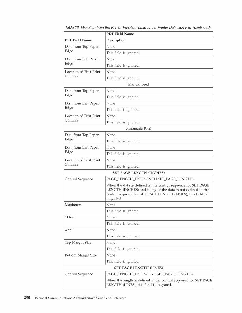
Table 33. Migration from the Printer Function Table to the Printer Definition File (continued)
PFT Field Name
PDF Field Name
Description
Dist. from Top PaperEdge
None
This field is ignored.
Dist. from Left PaperEdge
None
This field is ignored.
Location of First PrintColumn
None
This field is ignored.
Manual Feed
Dist. from Top PaperEdge
None
This field is ignored.
Dist. from Left PaperEdge
None
This field is ignored.
Location of First PrintColumn
None
This field is ignored.
Automatic Feed
Dist. from Top PaperEdge
None
This field is ignored.
Dist. from Left PaperEdge
None
This field is ignored.
Location of First PrintColumn
None
This field is ignored.
SET PAGE LENGTH (INCHES)
Control Sequence PAGE_LENGTH_TYPE?=INCH SET_PAGE_LENGTH=
When the data is defined in the control sequence for SET PAGELENGTH (INCHES) and if any of the data is not defined in thecontrol sequence for SET PAGE LENGTH (LINES), this field ismigrated.
Maximum None
This field is ignored.
Offset None
This field is ignored.
X/Y None
This field is ignored.
Top Margin Size None
This field is ignored.
Bottom Margin Size None
This field is ignored.
SET PAGE LENGTH (LINES)
Control Sequence PAGE_LENGTH_TYPE?=LINE SET_PAGE_LENGTH=
When the length is defined in the control sequence for SET PAGELENGTH (LINES), this field is migrated.
230 Personal Communications Administrator’s Guide and Reference

Table 33. Migration from the Printer Function Table to the Printer Definition File (continued)
PFT Field Name
PDF Field Name
Description
Maximum None
This field is ignored.
Offset None
This field is ignored.
X/Y None
This field is ignored.
Top Margin Size None
This field is ignored.
Bottom Margin Size None
This field is ignored.
SET LEFT MARGIN (INCHES)
Control Sequence None
This field is ignored.
Maximum None
This field is ignored.
Offset None
This field is ignored.
X/Y None
This field is ignored.
SET LEFT MARGIN (COLUMNS)
Control Sequence SET_HORIZONTAL_MARGIN=
When the data is defined in the control sequence field for SETLEFT MARGIN (COLUMNS), this field is migrated.
Maximum None
This field is ignored.
Offset None
This field is ignored.
CARRIER RETURN/LINE FEED
Continuous Forms
Chapter 18. Building a Printer Definition Table (PDT) for PC400 231
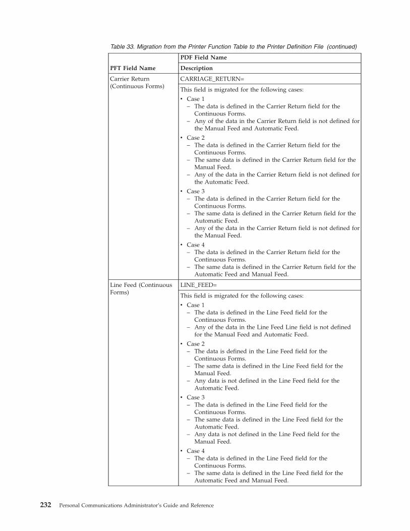
Table 33. Migration from the Printer Function Table to the Printer Definition File (continued)
PFT Field Name
PDF Field Name
Description
Carrier Return(Continuous Forms)
CARRIAGE_RETURN=
This field is migrated for the following cases:
v Case 1– The data is defined in the Carrier Return field for the
Continuous Forms.– Any of the data in the Carrier Return field is not defined for
the Manual Feed and Automatic Feed.
v Case 2– The data is defined in the Carrier Return field for the
Continuous Forms.– The same data is defined in the Carrier Return field for the
Manual Feed.– Any of the data in the Carrier Return field is not defined for
the Automatic Feed.
v Case 3– The data is defined in the Carrier Return field for the
Continuous Forms.– The same data is defined in the Carrier Return field for the
Automatic Feed.– Any of the data in the Carrier Return field is not defined for
the Manual Feed.
v Case 4– The data is defined in the Carrier Return field for the
Continuous Forms.– The same data is defined in the Carrier Return field for the
Automatic Feed and Manual Feed.
Line Feed (ContinuousForms)
LINE_FEED=
This field is migrated for the following cases:
v Case 1– The data is defined in the Line Feed field for the
Continuous Forms.– Any of the data in the Line Feed Line field is not defined
for the Manual Feed and Automatic Feed.
v Case 2– The data is defined in the Line Feed field for the
Continuous Forms.– The same data is defined in the Line Feed field for the
Manual Feed.– Any data is not defined in the Line Feed field for the
Automatic Feed.
v Case 3– The data is defined in the Line Feed field for the
Continuous Forms.– The same data is defined in the Line Feed field for the
Automatic Feed.– Any data is not defined in the Line Feed field for the
Manual Feed.
v Case 4– The data is defined in the Line Feed field for the
Continuous Forms.– The same data is defined in the Line Feed field for the
Automatic Feed and Manual Feed.
232 Personal Communications Administrator’s Guide and Reference

Table 33. Migration from the Printer Function Table to the Printer Definition File (continued)
PFT Field Name
PDF Field Name
Description
Manual Feed
Carrier Return (ManualFeed)
CARRIAGE_RETURN=
This field is migrated for the following cases:
v Case 1– The data is defined in the Line Feed field for the Manual
Feed.– Any of the data in the Line Feed Line field is not defined
for the Continuous Forms and Automatic Feed.
v Case 2– The data is defined in the Line Feed field for the Manual
Feed.– The same data is defined in the Line Feed field for the
Continuous Forms.– Any data is not defined in the Line Feed field for the
Automatic Feed.
v Case 3– The data is defined in the Line Feed field for the Manual
Feed.– The same data is defined in the Line Feed field for the
Automatic Feed.– Any data is not defined in the Line Feed field for the
Continuous Forms.
v Case 4– The data is defined in the Line Feed field for the Manual
Feed.– The same data is defined in the Line Feed field for the
Automatic Feed and Continuous Forms.
Chapter 18. Building a Printer Definition Table (PDT) for PC400 233

Table 33. Migration from the Printer Function Table to the Printer Definition File (continued)
PFT Field Name
PDF Field Name
Description
Line Feed (ManualFeed)
LINE_FEED=
This field is migrated for the following cases:
v Case 1– The data is defined in the Line Feed field for the Manual
Feed.– Any of the data in the Line Feed Line field is not defined
for the Continuous Forms and Automatic Feed.
v Case 2– The data is defined in the Line Feed field for the Manual
Feed.– The same data is defined in the Line Feed field for the
Continuous Forms.– Any data is not defined in the Line Feed field for the
Automatic Feed.
v Case 3– The data is defined in the Line Feed field for the Manual
Feed.– The same data is defined in the Line Feed field for the
Automatic Feed.– Any data is not defined in the Line Feed field for the
Continuous Forms.
v Case 4– The data is defined in the Line Feed field for the Manual
Feed.– The same data is defined in the Line Feed field for the
Automatic Feed and Continuous Forms.
Automatic Feed
234 Personal Communications Administrator’s Guide and Reference
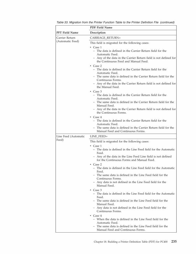
Table 33. Migration from the Printer Function Table to the Printer Definition File (continued)
PFT Field Name
PDF Field Name
Description
Carrier Return(Automatic Feed)
CARRIAGE_RETURN=
This field is migrated for the following cases:
v Case 1– The data is defined in the Carrier Return field for the
Automatic Feed.– Any of the data in the Carrier Return field is not defined for
the Continuous Feed and Manual Feed.
v Case 2– The data is defined in the Carrier Return field for the
Automatic Feed.– The same data is defined in the Carrier Return field for the
Continuous Forms.– Any of the data in the Carrier Return field is not defined for
the Manual Feed.
v Case 3– The data is defined in the Carrier Return field for the
Automatic Feed.– The same data is defined in the Carrier Return field for the
Manual Feed.– Any of the data in the Carrier Return field is not defined for
the Continuous Forms.
v Case 4– The data is defined in the Carrier Return field for the
Automatic Feed.– The same data is defined in the Carrier Return field for the
Manual Feed and Continuous Forms.
Line Feed (AutomaticFeed)
LINE_FEED=
This field is migrated for the following cases:
v Case 1– The data is defined in the Line Feed field for the Automatic
Feed.– Any of the data in the Line Feed Line field is not defined
for the Continuous Forms and Manual Feed.
v Case 2– The data is defined in the Line Feed field for the Automatic
Feed.– The same data is defined in the Line Feed field for the
Continuous Forms.– Any data is not defined in the Line Feed field for the
Manual Feed.
v Case 3– The data is defined in the Line Feed field for the Automatic
Feed.– The same data is defined in the Line Feed field for the
Manual Feed.– Any data is not defined in the Line Feed field for the
Continuous Forms.
v Case 4– When the data is defined in the Line Feed field for the
Automatic Feed.– The same data is defined in the Line Feed field for the
Manual Feed and Continuous Forms.
Chapter 18. Building a Printer Definition Table (PDT) for PC400 235

Table 33. Migration from the Printer Function Table to the Printer Definition File (continued)
PFT Field Name
PDF Field Name
Description
MULTIPLE COPIES
Print without Clearing Page from
Top Tray None
This field is ignored.
Bottom Tray None
This field is ignored.
Envelope Tray None
This field is ignored.
Manual Tray None
This field is ignored.
Clear Page Buffer None
This field is ignored.
Multiple Copies Variable Control
Control Sequence None
This field is ignored.
Maximum None
This field is ignored.
Offset None
This field is ignored.
LANDSCAPE PAPER HANDLING
Bottom Tray Feed
Bottom Tray Feed SET_LANDSCAPELEFT_ORIENT=
If the data is defined in some fields for LANDSCAPE PAPERHANDLING, the PFT Migration Utility assumes that this controlsequence includes the control sequence for the landscapeorientation. For this, the PFT Migration Utility divides the controlsequence into two parts. The control sequence for the drawerselect and paper feed is ignored because this control sequence ismigrated when the data for PAPER HANDLING is processed.The control sequence for landscape orientation is migrated toSET_LANDSCAPE_ORIENT=. (See “Definition of PAPERHANDLING Migration” on page 243.)
Top Tray Feed
Top Tray Feed SET_LANDSCAPELEFT_ORIENT=
If the data is defined in some fields for LANDSCAPE PAPERHANDLING, the PFT Migration Utility assumes that this controlsequence includes the control sequence for the landscapeorientation. For this, the PFT Migration Utility divides the controlsequence into two parts. The control sequence for the drawerselect and paper feed is ignored because this control sequence ismigrated when the data for PAPER HANDLING is processed.The control sequence for landscape orientation is migrated toSET_LANDSCAPE_ORIENT=. (See “Definition of PAPERHANDLING Migration” on page 243.)
236 Personal Communications Administrator’s Guide and Reference
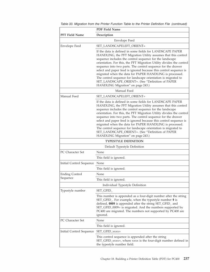
Table 33. Migration from the Printer Function Table to the Printer Definition File (continued)
PFT Field Name
PDF Field Name
Description
Envelope Feed
Envelope Feed SET_LANDSCAPELEFT_ORIENT=
If the data is defined in some fields for LANDSCAPE PAPERHANDLING, the PFT Migration Utility assumes that this controlsequence includes the control sequence for the landscapeorientation. For this, the PFT Migration Utility divides the controlsequence into two parts. The control sequence for the drawerselect and paper feed is ignored because this control sequence ismigrated when the data for PAPER HANDLING is processed.The control sequence for landscape orientation is migrated toSET_LANDSCAPE_ORIENT=. (See “Definition of PAPERHANDLING Migration” on page 243.)
Manual Feed
Manual Feed SET_LANDSCAPELEFT_ORIENT=
If the data is defined in some fields for LANDSCAPE PAPERHANDLING, the PFT Migration Utility assumes that this controlsequence includes the control sequence for the landscapeorientation. For this, the PFT Migration Utility divides the controlsequence into two parts. The control sequence for the drawerselect and paper feed is ignored because this control sequence ismigrated when the data for PAPER HANDLING is processed.The control sequence for landscape orientation is migrated toSET_LANDSCAPE_ORIENT=. (See “Definition of PAPERHANDLING Migration” on page 243.)
TYPESTYLE DEFINITION
Default Typestyle Definition
PC Character Set None
This field is ignored.
Initial Control Sequence None
This field is ignored.
Ending ControlSequence
None
This field is ignored.
Individual Typestyle Definition
Typestyle number SET_GFID_
This number is appended as a four-digit number after the stringSET_GFID_. For example, when the typestyle number 9 isdefined, 0009 is appended after the string SET_GFID_ andSET_GFID_0009= is migrated. And the numbers supported byPC400 are migrated. The numbers not supported by PC400 areignored.
PC Character Set None
This field is ignored.
Initial Control Sequence SET_GFID_xxxx=
This control sequence is appended after the stringSET_GFID_xxxx=, where xxxx is the four-digit number defined inthe typestyle number field.
Chapter 18. Building a Printer Definition Table (PDT) for PC400 237
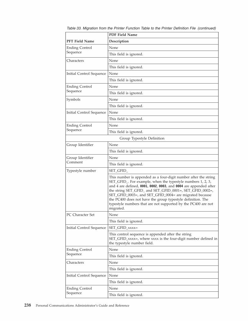
Table 33. Migration from the Printer Function Table to the Printer Definition File (continued)
PFT Field Name
PDF Field Name
Description
Ending ControlSequence
None
This field is ignored.
Characters None
This field is ignored.
Initial Control Sequence None
This field is ignored.
Ending ControlSequence
None
This field is ignored.
Symbols None
This field is ignored.
Initial Control Sequence None
This field is ignored.
Ending ControlSequence
None
This field is ignored.
Group Typestyle Definition
Group Identifier None
This field is ignored.
Group IdentifierComment
None
This field is ignored.
Typestyle number SET_GFID_
This number is appended as a four-digit number after the stringSET_GFID_. For example, when the typestyle numbers 1, 2, 3,and 4 are defined, 0001, 0002, 0003, and 0004 are appended afterthe string SET_GFID_ and SET_GFID_0001=, SET_GFID_0002=,SET_GFID_0003=, and SET_GFID_0004= are migrated becausethe PC400 does not have the group typestyle definition. Thetypestyle numbers that are not supported by the PC400 are notmigrated.
PC Character Set None
This field is ignored.
Initial Control Sequence SET_GFID_xxxx=
This control sequence is appended after the stringSET_GFID_xxxx=, where xxxx is the four-digit number defined inthe typestyle number field.
Ending ControlSequence
None
This field is ignored.
Characters None
This field is ignored.
Initial Control Sequence None
This field is ignored.
Ending ControlSequence
None
This field is ignored.
238 Personal Communications Administrator’s Guide and Reference
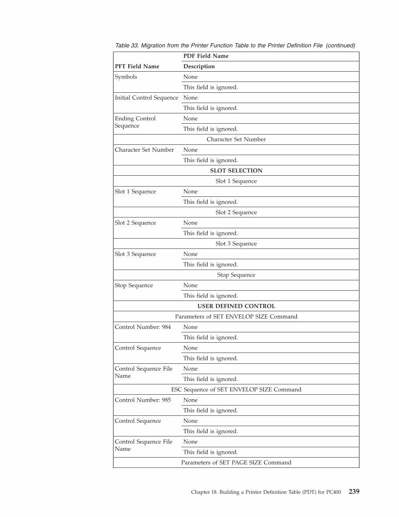
Table 33. Migration from the Printer Function Table to the Printer Definition File (continued)
PFT Field Name
PDF Field Name
Description
Symbols None
This field is ignored.
Initial Control Sequence None
This field is ignored.
Ending ControlSequence
None
This field is ignored.
Character Set Number
Character Set Number None
This field is ignored.
SLOT SELECTION
Slot 1 Sequence
Slot 1 Sequence None
This field is ignored.
Slot 2 Sequence
Slot 2 Sequence None
This field is ignored.
Slot 3 Sequence
Slot 3 Sequence None
This field is ignored.
Stop Sequence
Stop Sequence None
This field is ignored.
USER DEFINED CONTROL
Parameters of SET ENVELOP SIZE Command
Control Number: 984 None
This field is ignored.
Control Sequence None
This field is ignored.
Control Sequence FileName
None
This field is ignored.
ESC Sequence of SET ENVELOP SIZE Command
Control Number: 985 None
This field is ignored.
Control Sequence None
This field is ignored.
Control Sequence FileName
None
This field is ignored.
Parameters of SET PAGE SIZE Command
Chapter 18. Building a Printer Definition Table (PDT) for PC400 239
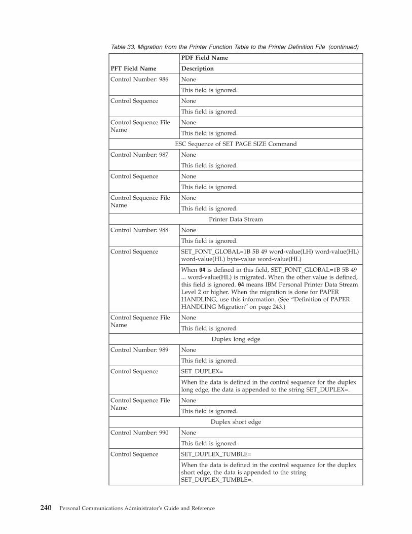
Table 33. Migration from the Printer Function Table to the Printer Definition File (continued)
PFT Field Name
PDF Field Name
Description
Control Number: 986 None
This field is ignored.
Control Sequence None
This field is ignored.
Control Sequence FileName
None
This field is ignored.
ESC Sequence of SET PAGE SIZE Command
Control Number: 987 None
This field is ignored.
Control Sequence None
This field is ignored.
Control Sequence FileName
None
This field is ignored.
Printer Data Stream
Control Number: 988 None
This field is ignored.
Control Sequence SET_FONT_GLOBAL=1B 5B 49 word-value(LH) word-value(HL)word-value(HL) byte-value word-value(HL)
When 04 is defined in this field, SET_FONT_GLOBAL=1B 5B 49... word-value(HL) is migrated. When the other value is defined,this field is ignored. 04 means IBM Personal Printer Data StreamLevel 2 or higher. When the migration is done for PAPERHANDLING, use this information. (See “Definition of PAPERHANDLING Migration” on page 243.)
Control Sequence FileName
None
This field is ignored.
Duplex long edge
Control Number: 989 None
This field is ignored.
Control Sequence SET_DUPLEX=
When the data is defined in the control sequence for the duplexlong edge, the data is appended to the string SET_DUPLEX=.
Control Sequence FileName
None
This field is ignored.
Duplex short edge
Control Number: 990 None
This field is ignored.
Control Sequence SET_DUPLEX_TUMBLE=
When the data is defined in the control sequence for the duplexshort edge, the data is appended to the stringSET_DUPLEX_TUMBLE=.
240 Personal Communications Administrator’s Guide and Reference

Table 33. Migration from the Printer Function Table to the Printer Definition File (continued)
PFT Field Name
PDF Field Name
Description
Control Sequence FileName
None
This field is ignored.
Simplex
Control Number: 991 None
This field is ignored.
Control Sequence RESET_DUPLEX=
When the data is defined in the control sequence for the simplex,the data is appended to the string RESET_DUPLEX=.
Control Sequence FileName
None
This field is ignored.
Jog the output tray
Control Number: 992 None
This field is ignored.
Control Sequence None
This field is ignored.
Control Sequence FileName
None
This field is ignored.
Normal portrait orientation
Control Number: 993 None
This field is ignored.
Control Sequence SET_PORTRAIT_ORIENT=
When the data is defined in the control field for the normalportrait orientation, the data is appended to the stringSET_PORTRAIT_ORIENT=.
Control Sequence FileName
None
This field is ignored.
Landscape left
Control Number: 994 None
This field is ignored.
Control Sequence SET_LANDSCAPELEFT_ORIENT=
When the data is defined in the control field for the landscapeleft, the data is appended to the stringSET_LANDSCAPELEFT_ORIENT=.
Control Sequence FileName
None
This field is ignored.
Portrait upside down orientation
Control Number: 995 None
This field is ignored.
Chapter 18. Building a Printer Definition Table (PDT) for PC400 241
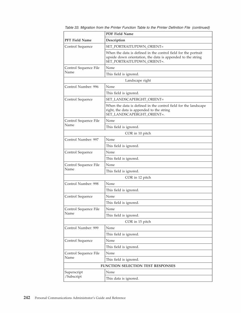
Table 33. Migration from the Printer Function Table to the Printer Definition File (continued)
PFT Field Name
PDF Field Name
Description
Control Sequence SET_PORTRAITUPDWN_ORIENT=
When the data is defined in the control field for the portraitupside down orientation, the data is appended to the stringSET_PORTRAITUPDWN_ORIENT=.
Control Sequence FileName
None
This field is ignored.
Landscape right
Control Number: 996 None
This field is ignored.
Control Sequence SET_LANDSCAPERGHT_ORIENT=
When the data is defined in the control field for the landscaperight, the data is appended to the stringSET_LANDSCAPERGHT_ORIENT=.
Control Sequence FileName
None
This field is ignored.
COR in 10 pitch
Control Number: 997 None
This field is ignored.
Control Sequence None
This field is ignored.
Control Sequence FileName
None
This field is ignored.
COR in 12 pitch
Control Number: 998 None
This field is ignored.
Control Sequence None
This field is ignored.
Control Sequence FileName
None
This field is ignored.
COR in 15 pitch
Control Number: 999 None
This field is ignored.
Control Sequence None
This field is ignored.
Control Sequence FileName
None
This field is ignored.
FUNCTION SELECTION TEST RESPONSES
Superscript/Subscript
None
This data is ignored.
242 Personal Communications Administrator’s Guide and Reference
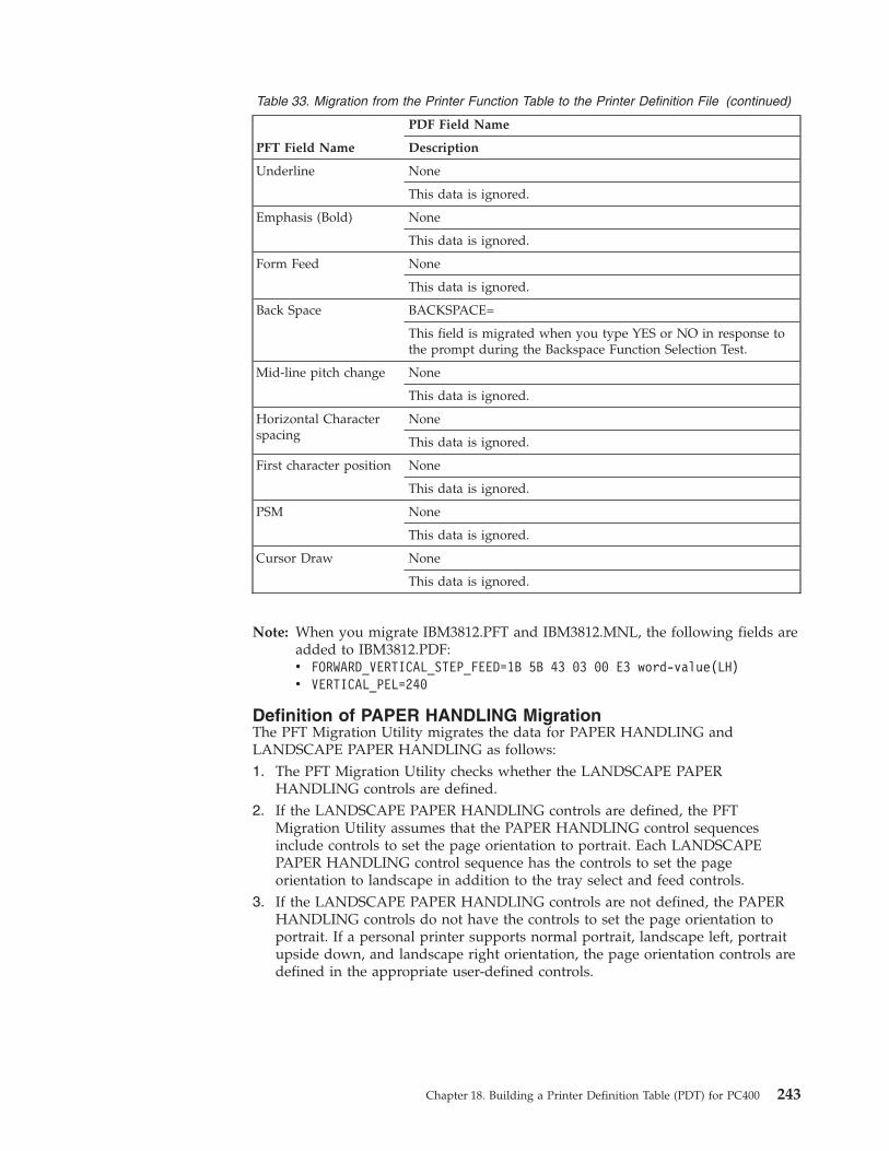
Table 33. Migration from the Printer Function Table to the Printer Definition File (continued)
PFT Field Name
PDF Field Name
Description
Underline None
This data is ignored.
Emphasis (Bold) None
This data is ignored.
Form Feed None
This data is ignored.
Back Space BACKSPACE=
This field is migrated when you type YES or NO in response tothe prompt during the Backspace Function Selection Test.
Mid-line pitch change None
This data is ignored.
Horizontal Characterspacing
None
This data is ignored.
First character position None
This data is ignored.
PSM None
This data is ignored.
Cursor Draw None
This data is ignored.
Note: When you migrate IBM3812.PFT and IBM3812.MNL, the following fields areadded to IBM3812.PDF:v FORWARD_VERTICAL_STEP_FEED=1B 5B 43 03 00 E3 word-value(LH)v VERTICAL_PEL=240
Definition of PAPER HANDLING MigrationThe PFT Migration Utility migrates the data for PAPER HANDLING andLANDSCAPE PAPER HANDLING as follows:1. The PFT Migration Utility checks whether the LANDSCAPE PAPER
HANDLING controls are defined.2. If the LANDSCAPE PAPER HANDLING controls are defined, the PFT
Migration Utility assumes that the PAPER HANDLING control sequencesinclude controls to set the page orientation to portrait. Each LANDSCAPEPAPER HANDLING control sequence has the controls to set the pageorientation to landscape in addition to the tray select and feed controls.
3. If the LANDSCAPE PAPER HANDLING controls are not defined, the PAPERHANDLING controls do not have the controls to set the page orientation toportrait. If a personal printer supports normal portrait, landscape left, portraitupside down, and landscape right orientation, the page orientation controls aredefined in the appropriate user-defined controls.
Chapter 18. Building a Printer Definition Table (PDT) for PC400 243
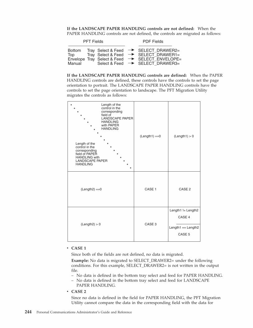
If the LANDSCAPE PAPER HANDLING controls are not defined: When thePAPER HANDLING controls are not defined, the controls are migrated as follows:
PFT Fields
BottomTopEnvelopeManual
TrayTrayTray
Select & FeedSelect & FeedSelect & FeedSelect & Feed
SELECT_DRAWER2=SELECT_DRAWER1=SELECT_ENVELOPE=SELECT_DRAWER3=
PDF Fields
If the LANDSCAPE PAPER HANDLING controls are defined: When the PAPERHANDLING controls are defined, these controls have the controls to set the pageorientation to portrait. The LANDSCAPE PAPER HANDLING controls have thecontrols to set the page orientation to landscape. The PFT Migration Utilitymigrates the controls as follows:
Length of thecontrol in thecorrespondingfield of PAPERHANDLING withLANDSCAPE PAPERHANDLING
Length of thecontrol in thecorrespondingfield ofLANDSCAPE PAPERHANDLINGwith PAPERHANDLING
(Length1) ==0
(Length2) ==0
(Length2) > 0
Length1 != Length2
CASE 4
Length1 == Length2
CASE 5
CASE 1
CASE 3
CASE 2
(Length1) > 0
v CASE 1
Since both of the fields are not defined, no data is migrated.Example: No data is migrated to SELECT_DRAWER2= under the followingconditions. For this example, SELECT_DRAWER2= is not written in the outputfile.– No data is defined in the bottom tray select and feed for PAPER HANDLING.– No data is defined in the bottom tray select and feed for LANDSCAPE
PAPER HANDLING.v CASE 2
Since no data is defined in the field for PAPER HANDLING, the PFT MigrationUtility cannot compare the data in the corresponding field with the data for
244 Personal Communications Administrator’s Guide and Reference

LANDSCAPE PAPER HANDLING. The data for LANDSCAPE PAPERHANDLING is migrated to the drawer selection field of PDF regardless,including control of the landscape orientation.Example: The control of the top tray select and feed for LANDSCAPE PAPERHANDLING is migrated to SELECT_DRAWER1= under the followingconditions.– No data is defined in the top tray select and feed for PAPER HANDLING.– The control is defined in the top tray select and feed for LANDSCAPE PAPER
HANDLING.v CASE 3
Since no data is defined in the field for LANDSCAPE PAPER HANDLING, thePFT Migration Utility cannot compare the data in the corresponding field withthe data for PAPER HANDLING. The data for PAPER HANDLING is migratedto the drawer selection field of PDF regardless, including the control of theportrait orientation.Example: The control of the manual select and feed for PAPER HANDLING ismigrated to SELECT_DRAWER3= under the following conditions.– The control is defined in the manual select and feed for PAPER HANDLING.– No data is defined in the top tray select and feed for LANDSCAPE PAPER
HANDLING.v CASE 4
Since the length is different, no data is migrated.Example: No data is migrated to SELECT_DRAWER2= under the followingconditions. For this example, SELECT_DRAWER2= is not written in the outputfile.– The data is defined in the bottom tray select and feed for PAPER
HANDLING and the length is 8.– The data is defined in the bottom tray select and feed for LANDSCAPE
PAPER HANDLING and the length is 10.v CASE 5
The PFT Migration Utility compares the data for PAPER HANDLING with thedata for LANDSCAPE PAPER HANDLING as follows:– If a different value is found in the data, search the control backward for the
escape character X'1B'.– If the escape character is found in the middle of the control, divide the
control into two parts. The PFT Migration Utility assumes that the first part isthe control for the tray select and feed, and the second part is the control forthe page orientation. The PFT Migration Utility migrates the first part of thePAPER HANDLING control into the tray select and feed, the second part ofthe PAPER HANDLING control into the SET_PORTRAIT_ORIENT=, and thesecond part of the LANDSCAPE PAPER HANDLING control intoSET_LANDSCAPELEFT_ORIENT=.
– If the escape character is found at the top of the control and 03 (= HP PCL) isdefined in the user-defined control 988, the PFT Migration Utility assumesthat the controls are combined. For this, the control begins with the escapecharacter and the two shared characters. For this, the PFT Migration Utilityassumes that the last character of the first part is a lowercase letter andconverts it to an uppercase letter to indicate that it is a terminating character.
Chapter 18. Building a Printer Definition Table (PDT) for PC400 245

The PFT Migration Utility divides the controls into the two parts as follows:
Migrated into SET_PORTRAIT_ORIENT=
Migrated into SET_LANDSCAPELEFT_ORIENT=
ESC
ESC
shared character
shared character
oo oo oo oo
oo oo oo oo
XX
XX
Different value
Different value
Converted uppercase
Migrated into the tray select and feed
< Control for LANDSCAPE PAPER HANDLING >
< Control for the PAPER HANDLING >
– If the escape character is found, but the data stream is not HP PCL, the PFTMigration Utility displays the error message to indicate that the PFTMigration Utility cannot migrate the data.
– If the escape character is not found, the PFT Migration Utility displays theerror message to indicate that the PFT Migration Utility cannot migrate thedata.
– If a different value is not found, the same control is defined for PAPERHANDLING and LANDSCAPE PAPER HANDLING.
The PFT Migration Utility migrates the data in the following order:1. Top Tray Select and Feed2. Bottom Tray Select and Feed3. Manual Select and Feed4. Envelope Tray Select and Feed
The migration stops for the page orientation, SET_PORTRAIT_ORIENT= andSET_LANDSCAPELEFT_ORIENT=, when the controls for the page orientation arefound. For example, the controls for the page orientation are found when the datais migrated for the Bottom Tray Select and Feed. The PFT Migration Utility doesnot care about the page orientation when migrating the data Manual Select andFeed, and Envelop Tray Select and Feed.
246 Personal Communications Administrator’s Guide and Reference

Part 6. Appendixes
© Copyright IBM Corp. 1989, 2002 247

248 Personal Communications Administrator’s Guide and Reference

Appendix A. Keyboard Layouts
This appendix describes keyboard layouts supported by the host system. Thekeyboards are selected during installation or customization procedures. You canuse keyboard layouts to locate character positions on the keyboard.
Different characters can appear in different key positions, depending on thecountry language selected. This appendix shows only U.S. keyboards. The functionkeys located across the top of the keyboard are not shown. Shaded areas showkeys that are not available on some U.S. keyboards. Refer to your Windowsdocumentation for more information about the country and code page options.Ask your system administrator for information about host code pages.
Personal Communications includes .KMP keyboard map files for 3270 and 5250sessions that map the standard Win32 hotkeys for Cut, Copy, and Paste to Ctrl+X,Ctrl+C and Ctrl+V, respectively.
For 5250 sessions, the default .KMP file is pcswinkb5.kmp. In this map file, the5250 key values for the following functions have also been changed: Enter andNew Line. The user can utilize the new keyboard map file, or may add these newkey values to an existing map file. The remapping is given in the following table.
Table 34. New Keyboard Map Functions for a 5250 Layout
Function of Key Key
Cut Ctrl+X
Copy Ctrl+C
Paste Ctrl+V
Enter Enter
New Line Right Ctrl
The PF7 and PF8 remain mapped to Roll Up and Roll Down, respectively.
For 3270 sessions, the default .KMP file is pcswinkb3.kmp. In this map file, the3270 key values for the following functions have also been changed: Page Up, PageDown, Enter and New Line. The user may utilize the new keyboard map file, ormay add these new key values to an existing map file. The remapping is given inthe following table.
Table 35. New Keyboard Map Functions for a 3270 Layout
Function of Key Key
Cut Ctrl+X
Copy Ctrl+C
Paste Ctrl+V
Page Up PF7
Page Down PF8
Enter Enter
New Line Right Ctrl
© Copyright IBM Corp. 1989, 2002 249
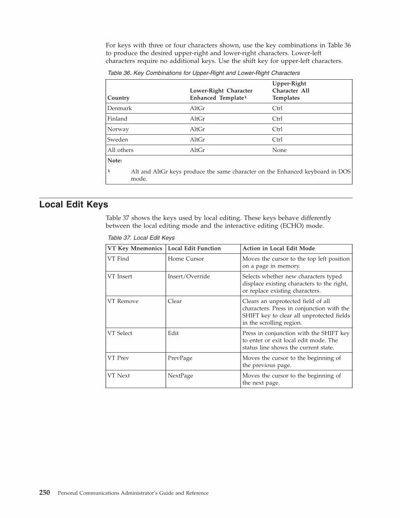
For keys with three or four characters shown, use the key combinations in Table 36to produce the desired upper-right and lower-right characters. Lower-leftcharacters require no additional keys. Use the shift key for upper-left characters.
Table 36. Key Combinations for Upper-Right and Lower-Right Characters
CountryLower-Right CharacterEnhanced Template¹
Upper-RightCharacter AllTemplates
Denmark AltGr Ctrl
Finland AltGr Ctrl
Norway AltGr Ctrl
Sweden AltGr Ctrl
All others AltGr None
Note:
¹ Alt and AltGr keys produce the same character on the Enhanced keyboard in DOSmode.
Local Edit KeysTable 37 shows the keys used by local editing. These keys behave differentlybetween the local editing mode and the interactive editing (ECHO) mode.
Table 37. Local Edit Keys
VT Key Mnemonics Local Edit Function Action in Local Edit Mode
VT Find Home Cursor Moves the cursor to the top left positionon a page in memory.
VT Insert Insert/Override Selects whether new characters typeddisplace existing characters to the right,or replace existing characters.
VT Remove Clear Clears an unprotected field of allcharacters. Press in conjunction with theSHIFT key to clear all unprotected fieldsin the scrolling region.
VT Select Edit Press in conjunction with the SHIFT keyto enter or exit local edit mode. Thestatus line shows the current state.
VT Prev PrevPage Moves the cursor to the beginning ofthe previous page.
VT Next NextPage Moves the cursor to the beginning ofthe next page.
250 Personal Communications Administrator’s Guide and Reference
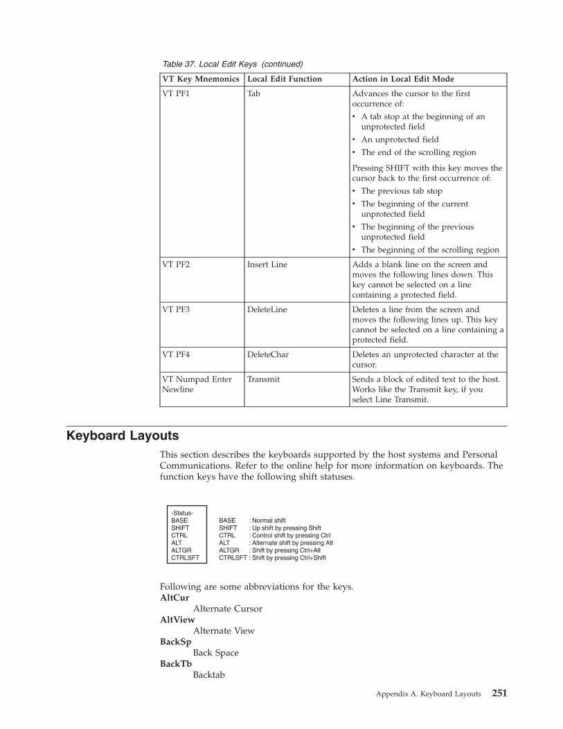
Table 37. Local Edit Keys (continued)
VT Key Mnemonics Local Edit Function Action in Local Edit Mode
VT PF1 Tab Advances the cursor to the firstoccurrence of:
v A tab stop at the beginning of anunprotected field
v An unprotected field
v The end of the scrolling region
Pressing SHIFT with this key moves thecursor back to the first occurrence of:
v The previous tab stop
v The beginning of the currentunprotected field
v The beginning of the previousunprotected field
v The beginning of the scrolling region
VT PF2 Insert Line Adds a blank line on the screen andmoves the following lines down. Thiskey cannot be selected on a linecontaining a protected field.
VT PF3 DeleteLine Deletes a line from the screen andmoves the following lines up. This keycannot be selected on a line containing aprotected field.
VT PF4 DeleteChar Deletes an unprotected character at thecursor.
VT Numpad EnterNewline
Transmit Sends a block of edited text to the host.Works like the Transmit key, if youselect Line Transmit.
Keyboard LayoutsThis section describes the keyboards supported by the host systems and PersonalCommunications. Refer to the online help for more information on keyboards. Thefunction keys have the following shift statuses.
Following are some abbreviations for the keys.AltCur
Alternate CursorAltView
Alternate ViewBackSp
Back SpaceBackTb
Backtab
-Status-BASESHIFTCTRLALTALTGRCTRLSFT
BASESHIFTCTRLALTALTGRCTRLSFT
: Normal shiftUp shift by pressing ShiftControl shift by pressing CtrlAlternate shift by pressing AltShift by pressing Ctrl+AltShift by pressing Ctrl+Shift
:::::
Appendix A. Keyboard Layouts 251

BgnOLnBegin of Line
BotOPgBottom of Page
BtbWordBacktab Word
CarRtnCarrier Return
ChgFmtChange Format
ChgScrnChange Screen
ChrAdvCharacter Advance
Ctrl ControlCurBlink
Cursor BlinkCurSel
Cursor SelectDelWord
Delete WordDevCan
Device CancelDspTxC
Display TextCodeDup DuplicateEditCop
Edit CopyEditPst
Edit PasteEditUnd
Edit UndoEndFld
End of FieldEndOLn
End of LineErEOF Erase EOFErFld Erase FieldErInp Erase InputFld- Field-Fld+ Field+FldColor
Field ColorFldExt Field ExitFldHigh
Field HighlightFldMark
Field MarkFldTrns
Transparency Field InheritFastDn
Fast DownFastDow
Fast DownFastUp
Fast Up
252 Personal Communications Administrator’s Guide and Reference

FieldColField Color
GrpCsrGraphic Cursor
HostPrHost Print
JmpNextJump Next
JumpNxtJump Next
MarkLefMark Left
MkDownMark Down
MkLeftMark Left
MkRightMark Right
MrkUpMark Up
MarkDowMark Down
MarkRigMark Right
MoveDowMove Down
MoveLefMove Left
MoveRigMove Right
MvDownMove Down
MvLeftMove Left
MvRightMove Right
MvUp Move UpNewLin
New LineReqBSp
Required BackspaceReqTab
Required TabRolDwn
Roll DownRollDow
Roll DownRolUp Roll UpRst/Ctrl
Reset/CtrlRPause
Record/Play PauseSOSI SOSI DisplaySOSI/G
SOSI Generate
Appendix A. Keyboard Layouts 253

SysAttnSystem Attention
SysReqSystem Request
TabFldTab Field
TopOPgTop of Page
TransOpTransparency Opaque
TrnfldITransparency Field Inherit
TrnOp Transparency OpaqueTstReq
Test RequestTurquois
TurquoiseUnderSc
UnderscoreUndScr
UnderscoreWdWrap
Word Wrap
254 Personal Communications Administrator’s Guide and Reference

Enhanced Keyboard, Microsoft Natural Keyboard (3270 Only)
Segment A assignment:
Segment B assignment:
A
B C D
110SysAttnSysReq--------------------
PF1PF13SOSIDocDocRed
PF2PF14-----WdWrapWdWrapPink
------------------------------
------------------------------
TabFldBackTab--------------------
------------------------------
------------------------------
Reset/CtrlReset/Ctrl-----QuitQuit-----
------------------------------
------------------------------
------------------------------
Enter/CtrlEnter/Ctrl--------------------
----------SUB
---------------
----------CAN
---------------
----------ETX
---------------
----------SYN
---------------
----------STX
---------------
----------SO
---------------
----------CR
---------------
------------------------------
------------------------------
------------------------------
------------------------------
----------SOH
---------------
----------DC3
---------------
----------EOT
---------------
----------ACK
---------------
----------BEL
---------------
----------BS
---------------
----------LF
---------------
----------VT
---------------
----------FF
---------------
------------------------------
------------------------------
NewLineNewLine--------------------
----------DC1
---------------
----------ETB
---------------
----------ENQ
---------------
----------DC2
---------------
----------DC4
---------------
----------EM
---------------
----------NAK
---------------
----------HT
---------------
----------SI
---------------
----------DLE
---------------
----------NUL
---------------
----------ESC
---------------
------------------------------
------------------------------
----------NUL
---------------
------------------------------
------------------------------
------------------------------
------------------------------
------------------------------
------------------------------
------------------------------
----------RS
---------------
----------US
---------------
----------RS
---------------
------------------------------
BackSpBackSp-----
----------
EditUnd
------------------------------
PF3PF15-----CfgFmtCfgFmtGreen
Clear-----Break---------------
PF4PF16---------------Yellow
PF5PF17Record----------Blue
PF6PF18Play----------Turq
PF7PF19RPause----------White
PF8PF20-----APLAPL
PF9PF21-----CurSelCurSel-----
PF11PF23RTMAltCurAltCur-----
PF12PF24-----+Cr+Cr-----
PF10PF22-----
-----
CurBlinkCurBlink
FldColor
112 113
125124
1
16
30
44
58 60 61 62 64
46 47 48 49 50 51 52 53 54 55 57
31 32 33 34 35 36 37 38 39 40 41 43
17 18 19 20 21 22 23 24 25 26 27 28 29
2 3 4 5 6 9 111087 12 13 14 15
114
126
115 116 117 118 119 120 123121 122
Appendix A. Keyboard Layouts 255

Segment C assignment: Segment D assignment:
Insert
Delete
HomeFMRulePA2PA2-----
UpMkupMvupFastUpFastUp-----
DownMkDownMvDown
-----
LeftMkLeftMvLeft
-----
Right
-----
FastDnFastDn
BtbWordBtbWord
MkRightMvRightTabWordTabWord
------------------------------
------------------------------
-------------------------TrnOp
---------------
-----
ErEOFErFld-----ErInpErInp-----
Home-------------------------
Left-----MyLeft---------------
------------------------------
Right-----
UndScrUndScr-----
MyRight
EndFld-------------------------
Insert-------------------------
Delete-----
-----
-------------------------
Esc J----------
-----
Up-----MvUpFastUpFastUp
Down-----MvDown
-----
FldTrns
FldHighFldHigh
DelWordDelWordDelWord
TrnFldI
FastDnFastDn
-----TabFld--------------------
EnterEnter--------------------
-----PA3
-----
-----
---------------
Dup
EditCut
PA1PA1
EditCop
DelWordDelWordDelWord
ChgScrnJmpNextJmpNext
ReverseReverse
EditPstTest
EditPst
-----
75
76
80
83
8479 89
90 10595 100
81 91
92 97 102
93
99 104
96
98
101
103
106
108
85
86
256 Personal Communications Administrator’s Guide and Reference

Enhanced Keyboard, Microsoft Natural Keyboard (5250 Only)
Segment A assignment:
Segment B assignment:
A
B C D
110SysAttnSysReq--------------------
PF1PF13SOSIHelp----------
PF2PF14--------------------
------------------------------
------------------------------
TabFldBackTbReqTab---------------
------------------------------
------------------------------
Reset/CtrlReset/Ctrl-----QuitQuit-----
------------------------------
------------------------------
------------------------------
Enter/CtrlEnter/Ctrl--------------------
------------------------------
------------------------------
------------------------------
------------------------------
------------------------------
------------------------------
------------------------------
------------------------------
------------------------------
------------------------------
------------------------------
------------------------------
------------------------------
------------------------------
------------------------------
------------------------------
------------------------------
------------------------------
------------------------------
------------------------------
------------------------------
------------------------------
FldExtNewLinCarRtn---------------
------------------------------
------------------------------
------------------------------
------------------------------
------------------------------
------------------------------
------------------------------
------------------------------
------------------------------
------------------------------
------------------------------
------------------------------
------------------------------
------------------------------
------------------------------
------------------------------
------------------------------
------------------------------
------------------------------
------------------------------
------------------------------
------------------------------
------------------------------
------------------------------
------------------------------
------------------------------
BackSpBackSpReqBSp---------------
------------------------------
PF3PF15--------------------
Clear-----HostPrTstReq----------
PF4PF16--------------------
PF5PF17Record---------------
PF6PF18Play---------------
PF7PF19RPause---------------
PF8PF20SOSI/G-----SOSI/G
PF9PF21--------------------
PF11PF23-----AltCurAltCur-----
PF12PF24-----TestReqTestReq-----
PF10PF22-----
-----
CurBlinkCurBlink
FieldCol
112 113
125124
1
16
30
44
58 60 61 62 64
46 47 48 49 50 51 52 53 54 55 57
31 32 33 34 35 36 37 38 39 40 41 43
17 18 19 20 21 22 23 24 25 26 27 28 29
2 3 4 5 6 9 111087 12 13 14 15
114
126
115 116 117 118 119 120 123121 122
Appendix A. Keyboard Layouts 257

Segment C assignment: Segment D assignment:
Insert
Delete
HomeFM
Rule---------------
UpMkupMvupFastUpFastUp-----
DownMkDownMvDown
-----
LeftMkLeftMvLeft
-----
Right
-----
FastDnFastDn
BtbWordBtbWord
MkRightMvRightTabWordTabWord
------------------------------
Fld-Fld-
CarRtnFld-Fld------
------------------------------
------------------------------
ErEOF----------ErInpErInp-----
Home-------------------------
Left-----BgnOLn---------------
------------------------------
Right-----
UndScrUndScr-----
EndOLn
ErEOF-------------------------
Ins-------------------------
Delete-----
-----
RolDwn-------------------------
RolUp-------------------------
Up-----TopOPgFastUpFastUp-----
Down-----BotOPg
-----
DelWordDelWordDelWord
FastDnFastDn
Fld+Fld+
CarRtnFld+Fld+-----
FldExtFldExt--------------------
RolDwnRolDwn-----JmpNxtJmpNxt-----
RolUp
--------------------
Dup
EditCut
----------
EditCop
DelWordDelWordDelWord
EditPst
EditPst
-----
75
76
80
83
8479 89
90 10595 100
81 91
92 97 102
93
99 104
96
98
101
103
106
108
85
86
258 Personal Communications Administrator’s Guide and Reference

Enhanced Keyboard, Microsoft Natural Keyboard (Combined3270 and 5250)
Segment A assignment:
Segment B assignment:
A
B C D
110SysAttnSysReq--------------------
PF1PF13SOSIDocDocRed
PF2PF14-----WdWrapWdWrapPink
------------------------------
------------------------------
TabFldBackTab--------------------
------------------------------
------------------------------
Reset/CtrlReset/Ctrl-----QuitQuit-----
------------------------------
------------------------------
------------------------------
Enter/CtrlEnter/Ctrl--------------------
----------SUB
---------------
----------CAN
---------------
----------ETX
---------------
----------SYN
---------------
----------STX
---------------
----------SO
---------------
----------CR
---------------
------------------------------
------------------------------
------------------------------
------------------------------
----------SOH
---------------
----------DC3
---------------
----------EOT
---------------
----------ACK
---------------
----------BEL
---------------
----------BS
---------------
----------LF
---------------
----------VT
---------------
----------FF
---------------
------------------------------
------------------------------
NewLineNewLine--------------------
----------DC1
---------------
----------ETB
---------------
----------ENQ
---------------
----------DC2
---------------
----------DC4
---------------
----------EM
---------------
----------NAK
---------------
----------HT
---------------
----------SI
---------------
----------DLE
---------------
----------NUL
---------------
----------ESC
---------------
------------------------------
------------------------------
----------NUL
---------------
------------------------------
------------------------------
------------------------------
------------------------------
------------------------------
------------------------------
------------------------------
------------------------------
----------US
---------------
----------RS
---------------
------------------------------
BackSpChrAdv--------------------
------------------------------
PF3PF15-----CfgFmtCfgFmtGreen
Clear-----Break---------------
PF4PF16---------------Yellow
PF5PF17Record----------Blue
PF6PF18Play----------Turq
PF7PF19RPause----------White
PF8PF20-----APLAPL
PF9PF21-----CurSelCurSel-----
PF11PF23RTMAltCurAltCur-----
PF12PF24-----+Cr+Cr-----
PF10PF22-----
-----
CurBlinkCurBlink
FldColor
112 113
125124
1
16
30
44
58 60 61 62 64
46 47 48 49 50 51 52 53 54 55 57
31 32 33 34 35 36 37 38 39 40 41 43
17 18 19 20 21 22 23 24 25 26 27 28 29
2 3 4 5 6 9 111087 12 13 14 15
114
126
115 116 117 118 119 120 123121 122
Appendix A. Keyboard Layouts 259

Segment C assignment: Segment D assignment:
Insert
Delete
HomeFM
RulePA2PA2
-----
UpMkupMvupFastUpFastUp-----
DownMkDownMvDown
-----
LeftMkLeftMvLeft
-----
Right
-----
FastDnFastDn
BtbWordBtbWord
MkRightMvRightTabWordTabWord
------------------------------
------------------------------
-------------------------TrnOp
---------------
ReverseReverse-----
ErEOFErFld-----ErInpErInp-----
Home-------------------------
Left-----MvLeft---------------
------------------------------
Right-----
MvRightUndScrUndScr-----
EndFld-------------------------
Delete-----
-----
-------------------------
Fldtrns
ESC J----------FldHighFldHigh-----
Up-----MvUp
FastUpFastUpTrnFldI
Down-----MvDownFastDnFastDn-----
DelWordDelWordDelWord
Field+TabFld--------------------
EnterEnter--------------------
RolDwnPA3ChgScrJmpNxtJmpNxt-----
RolUp
Test---------------
Dup
EditCut
PA1PA1
EditCop
DelWordDelWordDelWord
EditPst
EditPst
-----
75
76
80
83
8479 89
90 10595 100
81 91
92 97 102
93
99 104
96
98
101
103
106
108
85
86
Insert-------------------------
260 Personal Communications Administrator’s Guide and Reference
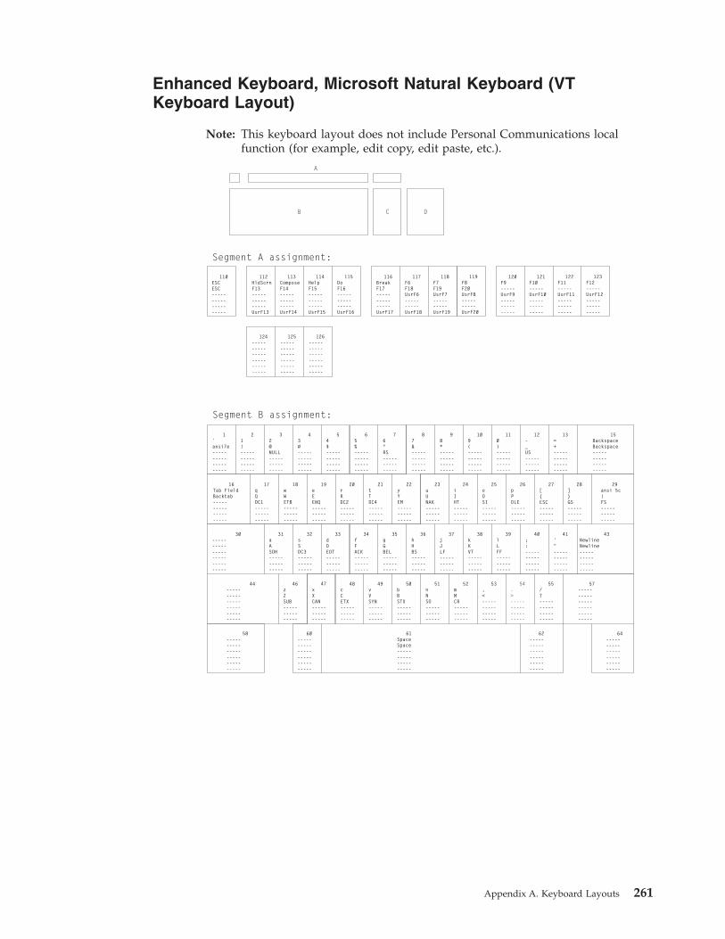
Enhanced Keyboard, Microsoft Natural Keyboard (VTKeyboard Layout)
Note: This keyboard layout does not include Personal Communications localfunction (for example, edit copy, edit paste, etc.).
110ESCESC--------------------
112HldScrnF13---------------UsrF13
54$--------------------
19eEENQ---------------
33dDEOT---------------
48cCETX---------------
98*--------------------
23uUNAK---------------
37jJLF---------------
52mMCR---------------
13=+--------------------
27[{ESC---------------
41'"--------------------
1`ansi7e--------------------
29ansi 5c|FS---------------
43NewlineNewline--------------------
57------------------------------
64------------------------------
116BreakF17---------------UsrF17
120F9-----UsrF9---------------
124------------------------------
113ComposeF14---------------UsrF14
65%--------------------
20rRDC2---------------
34fFACK---------------
49vVSYN---------------
62------------------------------
109(--------------------
24iIHT---------------
38kKVT---------------
53,<--------------------
28]}GS---------------
21!--------------------
16Tab FieldBacktab--------------------
30------------------------------
44------------------------------
117F6F18UsrF6----------UsrF18
121F10-----UsrF10---------------
125------------------------------
114HelpF15---------------UsrF15
76^RS---------------
21tTDC4---------------
35gGBEL---------------
50bBSTX---------------
60------------------------------
110)--------------------
25oOSI---------------
39lLFF---------------
54.>--------------------
15BackspaceBackspace--------------------
32@NULL---------------
17qQDC1---------------
31aASOH---------------
46zZSUB---------------
61SpaceSpace--------------------
118F7F19UsrF7----------UsrF19
122F11-----UsrF11---------------
126------------------------------
115DoF16---------------UsrF16
87&--------------------
22yYEM---------------
36hHBS---------------
51nNSO---------------
12-_US---------------
26pPDLE---------------
40;:--------------------
55/?--------------------
58------------------------------
43#--------------------
18wWETB---------------
32sSDC3---------------
47xXCAN---------------
119F8F20UsrF8----------UsrF20
123F12-----UsrF12---------------
Segment A assignment:
Segment B assignment:
A
B C D
Appendix A. Keyboard Layouts 261

Segment C assignment: Segment D assignment:
90-----PF1--------------------
91Selectnumpd 7--------------------
92Leftnumpd 4--------------------
93Findnumpd 1--------------------
99InsertHerenumpd 0--------------------
95-----PF2--------------------
96Upnumpd 8--------------------
97-----numpd 5--------------------
98Downnumpd 2--------------------
100-----PF3--------------------
101PrvScnnumpd 9--------------------
102Rightnumpd 6--------------------
103NxPgnumpd 3--------------------
104Removenumpd .--------------------
105-----PF4--------------------
106numpd —numpd ,--------------------
108-----numpd Newln--------------------
75InsertHere-------------------------
76Remove-------------------------
79Left-------------------------
80Select-------------------------
81Find-------------------------
83Up-------------------------
84Down-------------------------
85PrevScn-------------------------
86NextScn-------------------------
89Right-------------------------
262 Personal Communications Administrator’s Guide and Reference

Enhanced Keyboard, Microsoft Natural Keyboard (VT LocalEdit Mode Only)
Note: This keyboard layout does not include Personal Communications localfunction (for example, edit copy, edit paste, etc.).
110ESCESC--------------------
112HldScrnF13---------------UsrF13
54$--------------------
19eEENQ---------------
33dDEOT---------------
48cCETX---------------
98*--------------------
23uUNAK---------------
37jJLF---------------
52mMCR---------------
13=+--------------------
27[{ESC---------------
41'"--------------------
1`ansi7e--------------------
29ansi 5c|FS---------------
43Newline/TransmitNewline/Transmit--------------------
57------------------------------
64------------------------------
116BreakF17---------------UsrF17
120F9-----UsrF9---------------
124------------------------------
113ComposeF14---------------UsrF14
65%--------------------
20rRDC2---------------
34fFACK---------------
49vVSYN---------------
62------------------------------
109(--------------------
24iIHT---------------
38kKVT---------------
53,<--------------------
28]}GS---------------
21!--------------------
16Tab FieldBacktab--------------------
30------------------------------
44------------------------------
117F6F18UsrF6----------UsrF18
121F10-----UsrF10---------------
125------------------------------
114HelpF15---------------UsrF15
76^RS---------------
21tTDC4---------------
35gGBEL---------------
50bBSTX---------------
60------------------------------
110)--------------------
25oOSI---------------
39lLFF---------------
54.>--------------------
15BackspaceBackspace--------------------
32@NULL---------------
17qQDC1---------------
31aASOH---------------
46zZSUB---------------
61SpaceSpace--------------------
118F7F19UsrF7----------UsrF19
122F11-----UsrF11---------------
126------------------------------
115DoF16---------------UsrF16
87&--------------------
22yYEM---------------
36hHBS---------------
51nNSO---------------
12-_US---------------
26pPDLE---------------
40;:--------------------
55/?--------------------
58------------------------------
43#--------------------
18wWETB---------------
32sSDC3---------------
47xXCAN---------------
119F8F20UsrF8----------UsrF20
123F12-----UsrF12---------------
Segment A assignment:
Segment B assignment:
A
B C D
Appendix A. Keyboard Layouts 263

Segment C assignment: Segment D assignment:
90BkTabTabFld--------------------
91Selectnumpd 7--------------------
92Leftnumpd 4--------------------
93HmeCurnumpd 1--------------------
99Insert/Overstrikenumpd 0--------------------
95-----InsrtLn--------------------
96Upnumpd 8--------------------
97-----numpd 5--------------------
98Downnumpd 2--------------------
100-----DelLn--------------------
101PrvPgnumpd 9--------------------
102Rightnumpd 6--------------------
103NxPgnumpd 3--------------------
104ClrFldnumpd .--------------------
105-----DelChar--------------------
106numpd —numpd ,--------------------
108-----Transmit--------------------
75Insrt/Ovstrk-------------------------
76ClrFldClrPg--------------------
79Left-------------------------
80SelectEDIT--------------------
81HomeCur-------------------------
83Up-------------------------
84Down-------------------------
85PrevPg-------------------------
86NextPg-------------------------
89Right-------------------------
264 Personal Communications Administrator’s Guide and Reference

Space-Saving Keyboard (3270 Only)
Segment A assignment:
Segment B assignment:
A
B C
110SysAttnSysReq--------------------
PF1PF13-----DocDocRed
PF2PF14-----WdWrapWdWrapPink
------------------------------
------------------------------
TabFldBackTab--------------------
------------------------------
------------------------------
Reset/CtrlReset/Ctrl-----QuitQuit-----
------------------------------
------------------------------
------------------------------
Enter/CtrlEnter/Ctrl--------------------
------------------------------
------------------------------
------------------------------
------------------------------
------------------------------
------------------------------
------------------------------
------------------------------
------------------------------
------------------------------
------------------------------
------------------------------
------------------------------
------------------------------
------------------------------
------------------------------
------------------------------
------------------------------
------------------------------
------------------------------
------------------------------
------------------------------
NewLineNewLine--------------------
------------------------------
------------------------------
------------------------------
------------------------------
------------------------------
------------------------------
------------------------------
------------------------------
------------------------------
------------------------------
------------------------------
------------------------------
------------------------------
------------------------------
------------------------------
------------------------------
------------------------------
------------------------------
------------------------------
------------------------------
------------------------------
------------------------------
------------------------------
------------------------------
------------------------------
------------------------------
BackSpBackSp--------------------
------------------------------
PF3PF15-----CfgFmtCfgFmtGreen
Clear-----Break---------------
PF4PF16---------------Yellow
PF5PF17Record----------Blue
PF6PF18Play----------Turq
PF7PF19RPause----------White
PF8PF20-----APLAPL
PF9PF21-----CurSelCurSel-----
PF11PF23RTMAltCurAltCur-----
PF12PF24-----+Cr+Cr-----
PF10PF22-----
-----
CurBlinkCurBlink
FldColor
112 113
125124
1
16
30
44
58 60 61 62 64
46 47 48 49 50 51 52 53 54 55 57
31 32 33 34 35 36 37 38 39 40 41 43
17 18 19 20 21 22 23 24 25 26 27 28 29
2 3 4 5 6 9 111087 12 13 14 15
114
126
115 116 117 118 119 120 123121 122
Appendix A. Keyboard Layouts 265

Segment C assignment:
InsertDup-----PA1PA1-----
DeleteDelete
HomeFMRulePA2PA2-----
UpMkupMvupFastUpFastUp-----
DownMkDownMvDown
-----
LeftMkLeftMvLeft
-----
Right
-----
FastDnFastDn
BtbWordBtbWord
MkRightMvRightTabWordTabWord
ErEOFErFld-----ErInpErInp-----
-----PA3ChgScrnJmpNextJmpNext-----
----------Test---------------
DelWordDelWordDelWord-----
75
76
80
83
8479 89
81
85
86
266 Personal Communications Administrator’s Guide and Reference

Space-Saving Keyboard (5250 Only)
Segment A assignment:
Segment B assignment:
A
B C
110SysAttnSysReq--------------------
PF1PF13-----Help----------
PF2PF14--------------------
------------------------------
------------------------------
TabFldBackTbReqTab---------------
------------------------------
------------------------------
Reset/CtrlReset/Ctrl-----QuitQuit-----
------------------------------
------------------------------
------------------------------
Enter/CtrlEnter/Ctrl--------------------
------------------------------
------------------------------
------------------------------
------------------------------
------------------------------
------------------------------
------------------------------
------------------------------
------------------------------
------------------------------
------------------------------
------------------------------
------------------------------
------------------------------
------------------------------
------------------------------
------------------------------
------------------------------
------------------------------
------------------------------
------------------------------
------------------------------
FldExtNewLinCarRtn---------------
------------------------------
------------------------------
------------------------------
------------------------------
------------------------------
------------------------------
------------------------------
------------------------------
------------------------------
------------------------------
------------------------------
------------------------------
------------------------------
------------------------------
------------------------------
------------------------------
------------------------------
------------------------------
------------------------------
------------------------------
------------------------------
------------------------------
------------------------------
------------------------------
------------------------------
------------------------------
BackSpBackSpReqBSp---------------
------------------------------
PF3PF15--------------------
Clear-----HostPrTstReq----------
PF4PF16--------------------
PF5PF17Record---------------
PF6PF18Play---------------
PF7PF19RPause---------------
PF8PF20--------------------
PF9PF21--------------------
PF11PF23-----AltCurAltCur-----
PF12PF24--------------------
PF10PF22-----
-----
CurBlinkCurBlink
112 113
125124
1
16
30
44
58 60 61 62 64
46 47 48 49 50 51 52 53 54 55 57
31 32 33 34 35 36 37 38 39 40 41 43
17 18 19 20 21 22 23 24 25 26 27 28 29
2 3 4 5 6 9 111087 12 13 14 15
114
126
115 116 117 118 119 120 123121 122
Appendix A. Keyboard Layouts 267

Segment C assignment:
InsertDupDspTxC---------------
DeleteDelete
HomeFMRule---------------
UpMkupMvupFastUpFastUp-----
DownMkDownMvDown
-----
LeftMkLeftMvLeft
-----
Right
-----
FastDnFastDn
BtbWordBtbWord
MkRightMvRightTabWordTabWord
ErEOF----------ErInpErInp-----
RolDwnRolDwn-----JmpNxtJmpNxt-----
RolUpRolUp--------------------
DelWordDelWordDelWord-----
75
76
80
83
8479 89
81
85
86
268 Personal Communications Administrator’s Guide and Reference
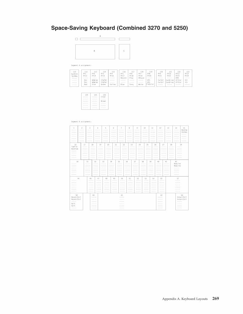
Space-Saving Keyboard (Combined 3270 and 5250)
Segment A assignment:
Segment B assignment:
A
B C
110SysAttnSysReq--------------------
PF1PF13-----DocDocRed
PF2PF14-----WdWrapWdWrapPink
------------------------------
------------------------------
TabFldBackTab--------------------
------------------------------
------------------------------
Reset/CtrlReset/Ctrl-----QuitQuit-----
------------------------------
------------------------------
------------------------------
Enter/CtrlEnter/Ctrl--------------------
------------------------------
------------------------------
------------------------------
------------------------------
------------------------------
------------------------------
------------------------------
------------------------------
------------------------------
------------------------------
------------------------------
------------------------------
------------------------------
------------------------------
------------------------------
------------------------------
------------------------------
------------------------------
------------------------------
------------------------------
------------------------------
------------------------------
NewLineNewLine--------------------
------------------------------
------------------------------
------------------------------
------------------------------
------------------------------
------------------------------
------------------------------
------------------------------
------------------------------
------------------------------
------------------------------
------------------------------
------------------------------
------------------------------
------------------------------
------------------------------
------------------------------
------------------------------
------------------------------
------------------------------
------------------------------
------------------------------
------------------------------
------------------------------
------------------------------
------------------------------
BackSpChrAdv--------------------
------------------------------
PF3PF15-----CfgFmtCfgFmtGreen
Clear-----Break---------------
PF4PF16---------------Yellow
PF5PF17Record----------Blue
PF6PF18Play----------Turq
PF7PF19RPause----------White
PF8PF20-----APLAPL
PF9PF21-----CurSelCurSel-----
PF11PF23RTMAltCurAltCur-----
PF12PF24-----+Cr+Cr-----
PF10PF22-----
-----
CurBlinkCurBlink
FldColor
112 113
125124
1
16
30
44
58 60 61 62 64
46 47 48 49 50 51 52 53 54 55 57
31 32 33 34 35 36 37 38 39 40 41 43
17 18 19 20 21 22 23 24 25 26 27 28 29
2 3 4 5 6 9 111087 12 13 14 15
114
126
115 116 117 118 119 120 123121 122
Appendix A. Keyboard Layouts 269

Segment C assignment:
InsertDup-----PA1PA1-----
DeleteDelete
HomeFMRulePA2PA2-----
UpMkupMvupFastUpFastUp-----
DownMkDownMvDown
-----
LeftMkLeftMvLeft
-----
Right
-----
FastDnFastDn
BtbWordBtbWord
MkRightMvRightTabWordTabWord
ErEOFErFld-----ErInpErInp-----
RolDwnPA3ChgScrnJmpNxtJmpNxt-----
RolUp-----Test---------------
DelWordDelWordDelWord-----
75
76
80
83
8479 89
81
85
86
270 Personal Communications Administrator’s Guide and Reference

5576-001 (3270 Only)
Segment A assignment:
112PF1PF13SOSIDoc
----------
113PF2PF14-----WordWrap----------
114PF3PF15AltViewCfgFmt----------
115PF4PF16--------------------
116PF5PF17--------------------
117PF6PF18--------------------
118PF7PF19--------------------
119PF8PF20APL-----APL-----
120PF9PF21--------------------
121PF10PF22--------------------
122PF11PF23--------------------
123PF12PF24-----GrpCsr----------
------------------------------
CrBrk----------AltCr----------
ErEOF----------ErInp----------
SysAttn----------CrSel----------
PA1----------DevCom----------
PA2----------PA3----------
Segment B assignment:
ResetReset-----Record----------
Play----------RPause----------
------------------------------
ClearClearSysReq---------------
------------------------------
1SysAttnSysReq--------------------
2------------------------------
3------------------------------
4------------------------------
5------------------------------
6------------------------------
7------------------------------
12----------
US---------------
13----------
RS---------------
15BackSpBackSp-----EditUnd----------
17----------DCI
---------------
18----------ETB
---------------
19----------ENQ
---------------
20----------DC2
---------------
21----------DC4
---------------
22----------EM
---------------
23----------NAK
---------------
24----------
HT---------------
25----------SI
---------------
26----------DLE
---------------
27----------NUL
---------------
28----------ESC
---------------
31----------SOH
---------------
32----------DC3
---------------
33----------EOT
---------------
34----------ACK
---------------
35----------BEL
---------------
36----------
BS---------------
37----------
LF---------------
38----------
VT---------------
39----------
FF---------------
40------------------------------
41------------------------------
46----------SUB
---------------
47----------CAN
---------------
48----------ETX
---------------
49----------SYN
---------------
50----------STX
---------------
51----------
SO---------------
52----------
CR---------------
53------------------------------
54------------------------------
55----------
FS---------------
60------------------------------
62------------------------------
16Tab
BackTab--------------------
29------------------------------
44------------------------------
30------------------------------
43NewLineNewLine-----NewLine----------
57------------------------------
58------------------------------
64Entr/CtlEntr/Ctl
--------------------
61------------------------------
BB
A
C D
------------------------------
------------------------------
------------------------------
------------------------------
------------------------------
------------------------------
------------------------------
------------------------------
------------------------------
------------------------------
------------------------------
8------------------------------
9------------------------------
10------------------------------
11------------------------------
14------------------------------
----------
GS---------------
Appendix A. Keyboard Layouts 271
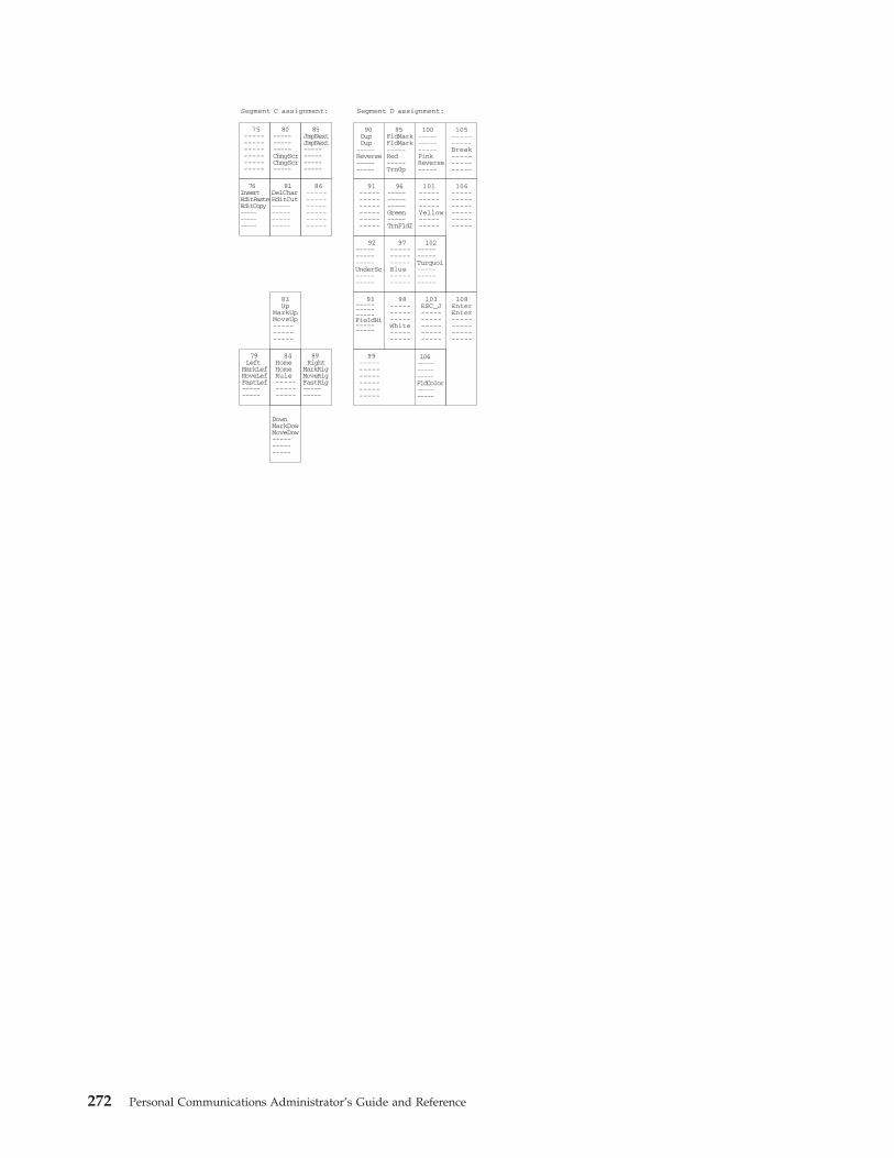
Segment C assignment:
75------------------------------
80---------------ChngScrChngScr-----
85JmpNextJmpNext--------------------
90DupDup
-----Reverse----------
95FldMarkFldMark-----Red-----Trn0p
100---------------PinkReverse-----
105----------Break---------------
76InsertEditPasteEditCopy---------------
81DelCharEditCut--------------------
86------------------------------
83Up
MarkUpMoveUp---------------
79Left
MarkLefMoveLefFastLef----------
84HomeHomeRule---------------
89Right
MarkRigMoveRigFastRig----------
DownMarkDowMoveDow---------------
91------------------------------
96---------------Green-----TrnFldI
101---------------Yellow----------
106------------------------------
92---------------UnderSc----------
97---------------Blue----------
102----------Turquoi---------------
93---------------FieldHi----------
98---------------White----------
103ESC_J-------------------------
108EnterEnter--------------------
99------------------------------
104---------------FldColor----------
Segment D assignment:
272 Personal Communications Administrator’s Guide and Reference
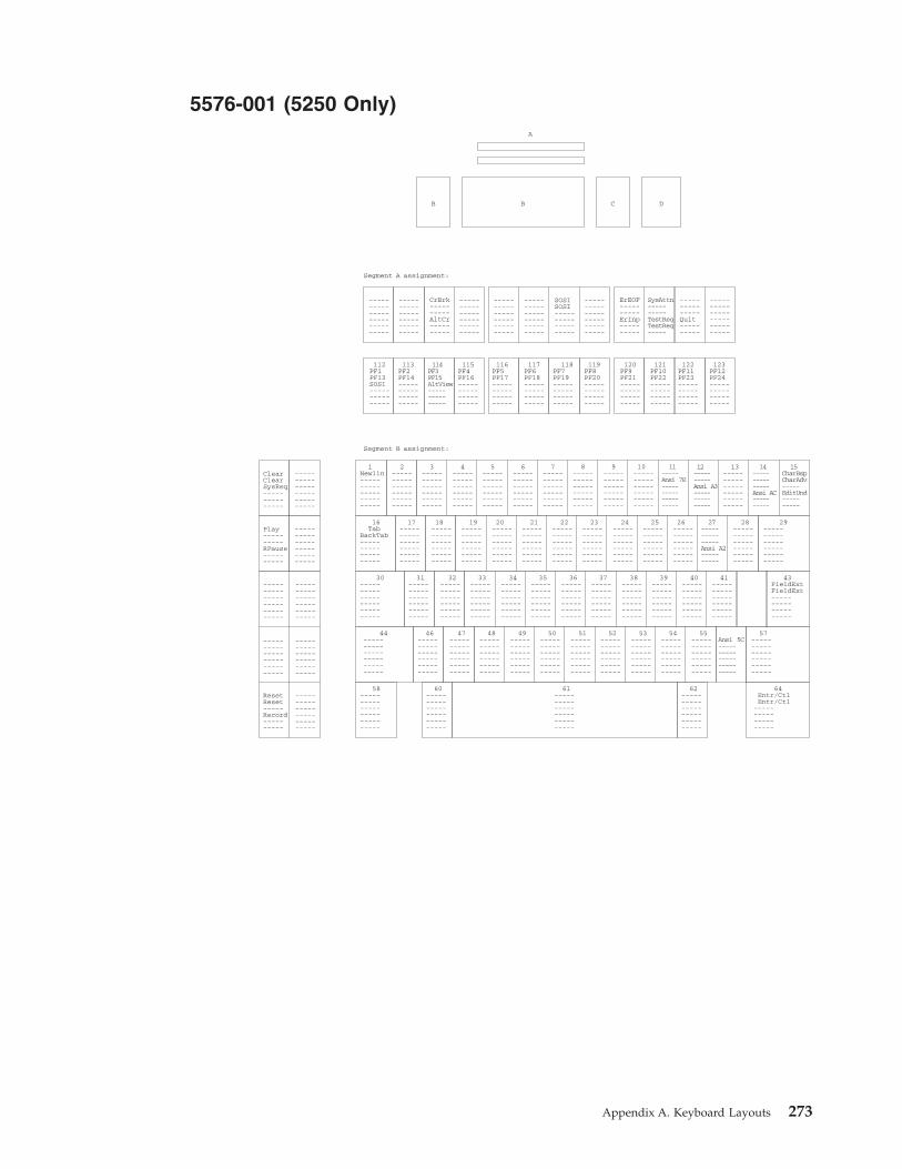
5576-001 (5250 Only)
Segment A assignment:
112PF1PF13SOSI---------------
113PF2PF14--------------------
114PF3PF15AltView---------------
115PF4PF16--------------------
116PF5PF17--------------------
117PF6PF18--------------------
118PF7PF19--------------------
119PF8PF20--------------------
120PF9PF21--------------------
121PF10PF22--------------------
122PF11PF23--------------------
123PF12PF24--------------------
------------------------------
CrBrk----------AltCr----------
ErEOF----------ErInp----------
SysAttn----------TestReqTestReq-----
---------------Quit----------
------------------------------
Segment B assignment:
ResetReset-----Record----------
Play----------RPause----------
------------------------------
ClearClearSysReq---------------
------------------------------
1Newlin-------------------------
2------------------------------
3------------------------------
4------------------------------
5------------------------------
6------------------------------
7------------------------------
12----------Ansi A3---------------
13------------------------------
15CharBspCharAdv-----EditUnd----------
17------------------------------
18------------------------------
19------------------------------
20------------------------------
21------------------------------
22------------------------------
23------------------------------
24------------------------------
25------------------------------
26------------------------------
27---------------Ansi A2----------
28------------------------------
31------------------------------
32------------------------------
33------------------------------
34------------------------------
35------------------------------
36------------------------------
37------------------------------
38------------------------------
39------------------------------
40------------------------------
41------------------------------
46------------------------------
47------------------------------
48------------------------------
49------------------------------
50------------------------------
51------------------------------
52------------------------------
53------------------------------
54------------------------------
55------------------------------
60------------------------------
62------------------------------
16Tab
BackTab--------------------
29------------------------------
44------------------------------
30------------------------------
43FieldExtFieldExt--------------------
57------------------------------
58------------------------------
64Entr/CtlEntr/Ctl
--------------------
61------------------------------
BB
A
C D
------------------------------
------------------------------
------------------------------
------------------------------
SOSISOSI--------------------
------------------------------
------------------------------
------------------------------
------------------------------
------------------------------
------------------------------
8------------------------------
9------------------------------
10------------------------------
11-----Ansi 7E--------------------
14---------------Ansi AC----------
Ansi 5C-------------------------
Appendix A. Keyboard Layouts 273

Segment C assignment:
75RollDwnRollDwn--------------------
80HomeFldMkRule---------------
85RollUpRollUp--------------------
90DupDupDupDupDup
-----
95FldMarkFldMarkFldMarkFldMarkFldMark-----
100------------------------------
105Field-Field-Field-Field-Field------
76InsertEditPasteEditCopy---------------
81DelChar-------------------------
86------------------------------
83Up
MarkUpMoveUpFastUp----------
79Left
MarkLefMoveLefFastLef----------
84HomeHomeRule---------------
89Right
MarkRigMoveRigFastRig----------
DownMarkDowMoveDowFastDow----------
91------------------------------
96------------------------------
101------------------------------
106Field+Field+Field+Field+Field+-----
92------------------------------
97------------------------------
102------------------------------
93------------------------------
98------------------------------
103------------------------------
108FldExtFldExt--------------------
99------------------------------
104------------------------------
Segment D assignment:
274 Personal Communications Administrator’s Guide and Reference

5576-001 (Combined 3270 and 5250)
Segment A assignment:
112PF1PF13SOSIDoc
----------
113PF2PF14-----WordWrap----------
114PF3PF15AltViewCfgFmt----------
115PF4PF16--------------------
116PF5PF17--------------------
117PF6PF18--------------------
118PF7PF19--------------------
119PF8PF20APL-----APL-----
120PF9PF21--------------------
121PF10PF22--------------------
122PF11PF23--------------------
123PF12PF24-----+Cr
----------
------------------------------
CrBnk----------AltCur----------
ErEOF----------ErInp----------
SysAttn----------CrSel----------
PA1----------DevCom----------
PA2----------PA3----------
Segment B assignment:
ResetReset-----Record----------
Play----------RPause----------
------------------------------
ClearClearSysReqSysReq----------
------------------------------
1SysAttn-------------------------
2------------------------------
3------------------------------
4------------------------------
5------------------------------
6------------------------------
7------------------------------
12----------USAnsi A3----------
13----------
RS---------------
15BackSpCharAdv--------------------
17----------DCI
---------------
18----------ETB
---------------
19----------ENQ
---------------
20----------DC2
---------------
21----------DC4
---------------
22----------EM
---------------
23----------NAK
---------------
24----------
HT---------------
25----------
SI---------------
26----------DLE
---------------
27----------NULAnsi A2----------
28----------ESC
---------------
31----------SOH
---------------
32----------DC3
---------------
33----------EOT
---------------
34----------ACK
---------------
35----------BEL
---------------
36----------
BS---------------
37----------
LF---------------
38----------
VT---------------
39----------
FF---------------
40------------------------------
41------------------------------
46----------
SUB---------------
47----------CAN
---------------
48----------ETX
---------------
49----------SYN
---------------
50----------STX
---------------
51----------
SO---------------
52----------
CR---------------
53------------------------------
54------------------------------
55------------------------------
60------------------------------
62------------------------------
16Tab
BackTab--------------------
29------------------------------
44------------------------------
30------------------------------
43NewLineNewLine--------------------
57------------------------------
58------------------------------
64Entr/CtlEntr/Ctl
--------------------
61------------------------------
BB
A
C D
------------------------------
------------------------------
HelpHelp--------------------
------------------------------
SOSISOSI--------------------
HostPrt-------------------------
------------------------------
------------------------------
------------------------------
------------------------------
------------------------------
8------------------------------
9------------------------------
10------------------------------
11-----Ansi 7E--------------------
14---------------Ansi A3----------
42----------GS
---------------
Ansi 5C-----FS
---------------
Appendix A. Keyboard Layouts 275

Segment C assignment:
75RollDwn-------------------------
80---------------ChgScrChgScr-----
85RollDwnJmpNext--------------------
90DupDup
-----Reverse----------
95FldMarkFldMark-----Red
-----Trn0p
100---------------Pink----------
105Field-Field-Break---------------
76InsertEditPasteEditCopy---------------
81DelCharEditCut--------------------
86------------------------------
83Up
MarkUpMoveUpFastUpFastUp-----
79Left
MarkLefMoveLefFastLef----------
84HomeHomeRule---------------
89Right
MarkRigMoveRigFastRig----------
DownMarkDowMoveDow---------------
91------------------------------
96---------------Green-----FldTrns
101---------------Yellow----------
106Field+Field+--------------------
92---------------UnderSc----------
97---------------Blue----------
102---------------Turquoi----------
93---------------FieldHi----------
98---------------White----------
103ESC_J-------------------------
108EnterEnter--------------------
99------------------------------
104---------------FldCol----------
Segment D assignment:
276 Personal Communications Administrator’s Guide and Reference

5576-A01 (3270 Only)
Segment A assignment:
Segment B assignment:
A
B C D
110SysAttnSysReq--------------------
PF1PF13SOSIDocDocRed
PF2PF14-----WordWrapWordWrapPink
------------------------------
------------------------------
TabBackTab--------------------
------------------------------
------------------------------
Reset/CtrlReset/Ctrl-----QuitQuit-----
------------------------------
------------------------------
------------------------------
Enter/CtlEnter/Ctl--------------------
----------SUB
---------------
----------CAN
---------------
----------ETX
---------------
----------SYN
---------------
----------STX
---------------
----------SO
---------------
----------CR
---------------
------------------------------
------------------------------
------------------------------
------------------------------
----------SOH
---------------
----------DC3
---------------
----------EOT
---------------
----------ACK
---------------
----------BEL
---------------
----------BS
---------------
----------LF
---------------
----------VT
---------------
----------FF
---------------
------------------------------
------------------------------
NewLineNewLine--------------------
----------DC1
---------------
----------ETB
---------------
----------ENQ
---------------
----------DC2
---------------
----------DC4
---------------
----------EM
---------------
----------NAK
---------------
----------HT
---------------
----------SI
---------------
----------DLE
---------------
----------NUL
---------------
----------ESC
---------------
------------------------------
------------------------------
----------NUL
---------------
------------------------------
------------------------------
------------------------------
------------------------------
------------------------------
------------------------------
------------------------------
----------RS
---------------
----------US
---------------
----------RS
---------------
------------------------------
BackSpBackSp-----
----------
EditUnd
------------------------------
PF3PF15AltViewCfgFmtCfgFmtGreen
Clear-----Break---------------
PF4PF16---------------Yellow
PF5PF17Record----------Blue
PF6PF18Play----------Turq
PF7PF19RPause----------White
PF8PF20APL-----APL
PF9PF21CrSel-----CrSel-----
PF11PF23RTMAltCrAltCr-----
PF12PF24-----GrpCsrGrpCsr-----
PF10PF22CrBnk-----CrBnk-----FldColor
112 113
125124
1
16
30
44
58 60 61 62 64
46 47 48 49 50 51 52 53 54 55 57
31 32 33 34 35 36 37 38 39 40 41 43
17 18 19 20 21 22 23 24 25 26 27 28 29
2 3 4 5 6 9 111087 12 13 14 15
114
126
115 116 117 118 119 120 123121 122
Appendix A. Keyboard Layouts 277
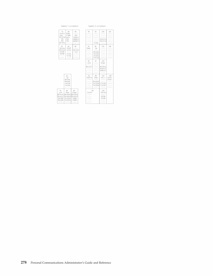
Segment C assignment: Segment D assignment:
Insert
Delete
HomeFldMkRulePA2PA2-----
UpMarkUpMoveUpFastUpFastUp-----
DownMarkDowMoveDowFastDowFastDow-----
LeftMarkLefMoveLefBackWdBackWd-----
RightMarkRigMoveRigFwdWdFwdWd-----
------------------------------
-------------------------TrnOp
------------------------------
---------------
ReverseReverse-----
ErEOFErFld-----ErInpErInp-----
Home-------------------------
Left-----
MovLeft---------------
------------------------------
Right-----
MoveRigUnderScUnderSc-----
EndFld-------------------------
Insert-------------------------
Delete-----
----------
------------------------------
------------------------------
ESC J----------
FieldHiFieldHi-----
Up-----MoveUpFastUpFastUpTrnFldI
Down-----
MoveDowFastDowFastDow-----
DelWdDelWd
EnterEnter--------------------
-----PA3
ChgScnJmpNextJmpNext-----
-----EditPstTest---------------
Dup
EditCut
PA1PA1
EditCop
DelWdDelWd-----
EditPst
-----
75
76
80
83
8479 89
90 10595 100
81 91
92 97 102
93
99 104
96
98
101
103
106
108
85
86
278 Personal Communications Administrator’s Guide and Reference
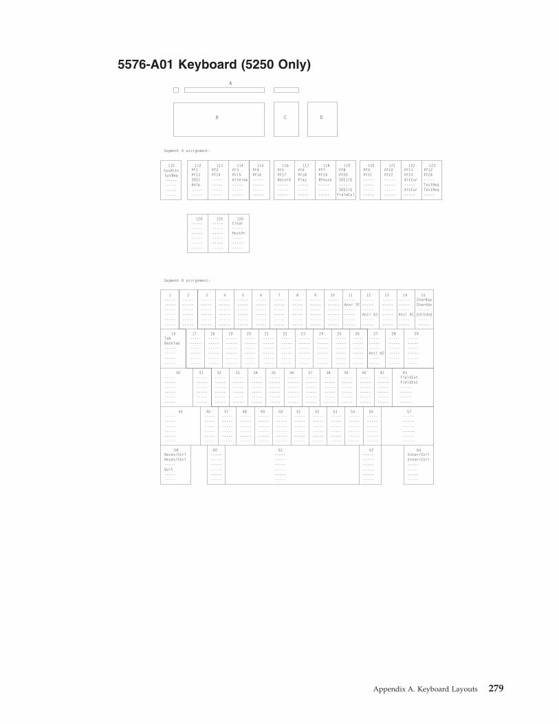
5576-A01 Keyboard (5250 Only)
Segment A assignment:
Segment B assignment:
A
B C
110SysAttnSysReq--------------------
PF1PF13SOSIHelp----------
PF2PF14--------------------
------------------------------
------------------------------
TabBackTab--------------------
------------------------------
------------------------------
Reset/CtrlReset/Ctrl-----Quit----------
------------------------------
------------------------------
------------------------------
Enter/CtrlEnter/Ctrl--------------------
------------------------------
------------------------------
------------------------------
------------------------------
------------------------------
------------------------------
------------------------------
------------------------------
------------------------------
------------------------------
------------------------------
------------------------------
------------------------------
------------------------------
------------------------------
------------------------------
------------------------------
------------------------------
------------------------------
------------------------------
------------------------------
------------------------------
FieldExtFieldExt--------------------
------------------------------
------------------------------
------------------------------
------------------------------
------------------------------
------------------------------
------------------------------
------------------------------
------------------------------
------------------------------
---------------Ansi A2----------
------------------------------
------------------------------
------------------------------
------------------------------
------------------------------
------------------------------
------------------------------
------------------------------
-----Ansi 7E--------------------
------------------------------
------------------------------
------------------------------
---------------Ansi A3----------
------------------------------
---------------Ansi AC----------
CharBspCharAdv-----
EditUnd----------
------------------------------
PF3PF15AltView---------------
Clear-----HostPr---------------
PF4PF16--------------------
PF5PF17Record---------------
PF6PF18Play---------------
PF7PF19RPause---------------
PF8PF20SOSI/G-----SOSI/G
PF9PF21--------------------
PF11PF23AltCur-----AltCur-----
PF12PF24-----TestReqTestReq-----
PF10PF22--------------------FieldCol
112 113
125124
1
16
30
44
58 60 61 62 64
46 47 48 49 50 51 52 53 54 55 57
31 32 33 34 35 36 37 38 39 40 41 43
17 18 19 20 21 22 23 24 25 26 27 28 29
2 3 4 5 6 9 111087 12 13 14 15
114
126
115 116 117 118 119 120 123121 122
D
Appendix A. Keyboard Layouts 279

Segment C assignment: Segment D assignment:
Insert
Delete
HomeFldMkRule---------------
UpMarkUpMoveUpFastUpFastUp-----
DownMarkDowMoveDowFastDowFastDow-----
LeftMarkLefMoveLefBackWdBackWd-----
RightMarkRigMoveRigTabWordTabWord-----
Ansi 2DAnsi 2DField-Field-Field------
FldMkFldMkFldMkFldMkFldMk-----
DupDup
--------------------
------------------------------
ErEOF----------ErInpErInp-----
Home-------------------------
Left-----
MoveLft---------------
------------------------------
Right-----
MoveRig---------------
ErEOF-------------------------
Insert-------------------------
Delete-----
----------
RollDwn-------------------------
RollUp-------------------------
Up-----MoveUpFastUpFastUp-----
Down-----
MoveDowFastDowFastDow-----
DelWordDelWord
Field+Field+Field+Field+Field+-----
FldExtFldExt--------------------
RollDwnRollDwn-----
JumpNxtJumpNxt-----
RollUpEditPst--------------------
Dup
EditCut
----------
EditCop
DelWdDelWd-----
EditPst
-----
75
76
80
83
8479 89
90 10595 100
81 91
92 97 102
93
99 104
96
98
101
103
106
108
85
86
280 Personal Communications Administrator’s Guide and Reference

5576-A01 Keyboard (Combined 3270 and 5250)
Segment A assignment:
Segment B assignment:
A
B C D
110Attn
SysReq--------------------
PF1PF13SOSIDocDocRed
PF2PF14-----WordWrapWordWrapPink
------------------------------
------------------------------
TabBackTab--------------------
------------------------------
------------------------------
Reset/CtrlReset/Ctrl-----QuitQuit-----
------------------------------
------------------------------
------------------------------
Enter/CtlEnter/Ctl--------------------
----------SUB
---------------
----------CAN
---------------
----------ETX
---------------
----------SYN
---------------
----------STX
---------------
----------SO
---------------
----------CR
---------------
------------------------------
------------------------------
------------------------------
------------------------------
----------SOH
---------------
----------DC3
---------------
----------EOT
---------------
----------ACK
---------------
----------BEL
---------------
----------BS
---------------
----------LF
---------------
----------VT
---------------
----------FF
---------------
------------------------------
------------------------------
NewLineNewLine--------------------
----------DC1
---------------
----------ETB
---------------
----------ENQ
---------------
----------DC2
---------------
----------DC4
---------------
----------EM
---------------
----------NAK
---------------
----------HT
---------------
----------SI
---------------
----------DLE
---------------
----------NUL
ANSI A2----------
----------ESC
---------------
------------------------------
------------------------------
----------NUL
---------------
------------------------------
------------------------------
------------------------------
------------------------------
-----ANSI 7E--------------------
------------------------------
------------------------------
------------------------------
----------US
ANSI A3----------
----------RS
---------------
---------------
ANSI AC----------
BackSpCharAdv--------------------
------------------------------
PF3PF15AltViewCfgFmtCfgFmtGreen
Clear-----Break---------------
PF4PF16---------------Yellow
PF5PF17Record----------Blue
PF6PF18Play----------Turquois
PF7PF19RPause----------White
PF8PF20APL-----APL-----
PF9PF21-----CrSelCrSel-----
PF11PF23AltCur-----AltCur-----
PF12PF24-----+Cr+Cr-----
PF10PF22CrBnk-----CrBnk-----
112 113
125124
1
16
30
44
58 60 61 62 64
46 47 48 49 50 51 52 53 54 55 57
31 32 33 34 35 36 37 38 39 40 41 43
17 18 19 20 21 22 23 24 25 26 27 28 29
2 3 4 5 6 9 111087 12 13 14 15
114
126
115 116 117 118 119 120 123121 122
Appendix A. Keyboard Layouts 281

Segment C assignment: Segment D assignment:
Insert
Delete
HomeFieldMkRulePA2PA2-----
UpMarkUpMoveUpFastUpFastUp-----
DownMarkDowMoveDowFastDowFastDow-----
LeftMarkLefMoveLefBackWdBackWd-----
RightMarkRigMoveRigFwdWdFwdWd-----
------------------------------
-------------------------TrnOp
ANSI 2DANSI 2D--------------------
---------------
ReverseReverse-----
ErEOFErFld-----ErInpErInp-----
Home-------------------------
Left-----
MoveLet---------------
------------------------------
Right-----
MoveRigUnderScUnderSc-----
EndFld-------------------------
Insert-------------------------
Delete-----
----------
------------------------------
Field-------------------------
ESC J----------
FieldHiFieldHi-----
Up-----MoveUpFastUpFastUpTrnFldI
Down-----
MoveDowFastDowFastDow-----
DelWordDelWord
EnterEnter--------------------
RollDwnPA3
ChgScnJumpNxtJumpNxt-----
RollUpEditPstTest---------------
Dup
EditCut
PA1PA1
EditCop
DelWordDelWord-----
EditPst
-----
75
76
80
83
8479 89
90 10595 100
81 91
92 97 102
93
99 104
96
98
101
103
106
108
85
86
282 Personal Communications Administrator’s Guide and Reference

5576-002/003 (3270 Only)
Segment A assignment:
Segment B assignment:
A
B C D
110SysattnSysRq--------------------
PF1PF13SOSIDocDocRed
PF2PF14-----WordWrapWordWrapPink
------------------------------
------------------------------
TabBackTab--------------------
------------------------------
------------------------------
Reset/CtrlReset/Ctrl-----QuitQuit-----
------------------------------
------------------------------
------------------------------
Entr/CtlEntr/Ctl--------------------
----------SUB
---------------
----------CAN
---------------
----------ETX
---------------
----------SYN
---------------
----------STX
---------------
----------SO
---------------
----------CR
---------------
------------------------------
------------------------------
------------------------------
------------------------------
----------SOH
---------------
----------DC3
---------------
----------EOT
---------------
----------ACK
---------------
----------BEL
---------------
----------BS
---------------
----------LF
---------------
----------VT
---------------
----------FF
---------------
------------------------------
------------------------------
NewLineNewLine--------------------
----------DC1
---------------
----------ETB
---------------
----------ENQ
---------------
----------DC2
---------------
----------DC4
---------------
----------EM
---------------
----------NAK
---------------
----------HT
---------------
----------SI
---------------
----------DLE
---------------
----------NUL
---------------
----------ESC
---------------
------------------------------
------------------------------
----------NUL
---------------
------------------------------
------------------------------
------------------------------
------------------------------
------------------------------
------------------------------
------------------------------
----------RS
---------------
----------US
---------------
----------RS
---------------
------------------------------
BackSpBackSp-----
EditUnd----------
------------------------------
PF3PF15AltViewCfgFmtCfgFmtGreen
Clear-----Break---------------
PF4PF16---------------Yellow
PF5PF17Record----------Blue
PF6PF18Play----------Turquois
PF7PF19RPause----------White
PF8PF20APL-----APLFieldCol
PF9PF21CrSel-----CrSel-----
PF11PF23RTMAltCrAltCr-----
PF12PF24-----GrpCsrGrpCsr-----
PF10PF22CrBnk-----CrBnk-----
112 113
125124
1
16
30
44
58 60 61 62 64
46 47 48 49 50 51 52 53 54 55 57
31 32 33 34 35 36 37 38 39 40 41 43
17 18 19 20 21 22 23 24 25 26 27 28 29
2 3 4 5 6 9 111087 12 13 14 15
114
126
115 116 117 118 119 120 123121 122
Appendix A. Keyboard Layouts 283

Segment C assignment: Segment D assignment:
Insert
Delete
HomeFldMkRulePA2PA2-----
UpMarkUpMoveUpFastUpFastUp-----
DownMarkDowMoveDowFastDowFastDow-----
LeftMarkLefMoveLefBackWdBackWd-----
RightMarkRigMoveRigFwdWdFwdWd-----
------------------------------
-------------------------TrnOp
------------------------------
---------------
ReverseReverse-----
ErEOFErFld-----ErInpErInp-----
Home-------------------------
Left-----
MovLeft---------------
------------------------------
Right-----
MoveRigUnderScUnderSc-----
EndFld-------------------------
Insert-------------------------
Delete-----
----------
------------------------------
------------------------------
ESC J----------
FieldHiFieldHi-----
Up-----MoveUpFastUpFastUpTrnFldI
Down-----
MoveDowFastDowFastDow-----
DelWdDelWd
EnterEnter--------------------
-----PA3
ChgScnJmpNextJmpNext-----
-----EditPstTest---------------
Dup
EditCut
PA1PA1
EditCop
DelWdDelWd-----
EditPst
-----
75
76
80
83
8479 89
90 10595 100
81 91
92 97 102
93
99 104
96
98
101
103
106
108
85
86
284 Personal Communications Administrator’s Guide and Reference

5576-002/003 Keyboard (5250 Only)
Segment A assignment:
Segment B assignment:
A
B C D
110SysAttnSysReq--------------------
PF1PF13SOSIHelp----------
PF2PF14--------------------
------------------------------
------------------------------
TabBackTab--------------------
------------------------------
------------------------------
------------------------------
------------------------------
------------------------------
------------------------------
------------------------------
------------------------------
------------------------------
------------------------------
------------------------------
Reset/CtlReset/Ctl-----Quit----------
------------------------------
------------------------------
------------------------------
Entr/CtlEntr/Ctl--------------------
------------------------------
------------------------------
------------------------------
------------------------------
------------------------------
------------------------------
------------------------------
------------------------------
------------------------------
------------------------------
------------------------------
------------------------------
------------------------------
FieldExtFieldExt--------------------
------------------------------
------------------------------
------------------------------
------------------------------
------------------------------
------------------------------
------------------------------
------------------------------
------------------------------
------------------------------
---------------
Ansi A2----------
------------------------------
------------------------------
------------------------------
------------------------------
------------------------------
------------------------------
------------------------------
------------------------------
-----Ansi 7E--------------------
------------------------------
------------------------------
------------------------------
---------------
Ansi A3----------
----------RS
---------------
---------------
ANSI AC----------
CharBspCharAdv-----
EditUnd----------
------------------------------
PF3PF15AltView---------------
Clear-----HostPr---------------
PF4PF16--------------------
PF5PF17Record---------------
PF6PF18Play---------------
PF7PF19Pause
---------------
PF8PF20SOSI/G-----SOSI/GFieldCol
PF9PF21--------------------
PF11PF23AltCur-----AltCur-----
PF12PF24-----TestReqTestReq-----
PF10PF22--------------------
112 113
125124
1
16
30
44
58 60 61 62 64
46 47 48 49 50 51 52 53 54 55 57
31 32 33 34 35 36 37 38 39 40 41 43
17 18 19 20 21 22 23 24 25 26 27 28 29
2 3 4 5 6 9 111087 12 13 14 15
114
126
115 116 117 118 119 120 123121 122
Appendix A. Keyboard Layouts 285

Segment C assignment: Segment D assignment:
Insert
Delete
HomeFldMkRule---------------
UpMarkUpMoveUpFastUpFastUp-----
DownMarkDowMoveDowFastDowFastDow-----
LeftMarkLefMoveLefBackWdBackWd-----
RightMarkRigMoveRigTabWordTabWord-----
DupDupDupDupDup
-----
ANSI 2DANSI 2D--------------------
FldMkFldMkFldMkFldMkFldMk-----
------------------------------
ErEOF----------ErInpErInp-----
Home-------------------------
Left-----
MoveLft---------------
------------------------------
Right-----
MoveRig---------------
ErEOF-------------------------
Insert-------------------------
Delete-----
----------
RollDwn-------------------------
RollUp-------------------------
Up-----MoveUpFastUpFastUp-----
Down-----
MoveDowFastDowFastDow-----
DelWordDelWord
Field+Field+Field+Field+Field+-----
FldExtFldExt--------------------
RollDwnRollDwn-----
JumpNxtJumpNxt-----
RollUpEditPst--------------------
Dup
EditCut
----------
EditCop
DelWdDelWd-----
EditPst
-----
75
76
80
83
8479 89
90 10595 100
81 91
92 97 102
93
99 104
96
98
101
103
106
108
85
86
286 Personal Communications Administrator’s Guide and Reference

5576-002/003 Keyboard (Combined 3270 and 5250)
Segment A assignment:
Segment B assignment:
A
B C D
110Attn
SysReq--------------------
PF1PF13SOSIDocDocRed
PF2PF14-----WordWrapWordWrapPink
------------------------------
------------------------------
TabBackTab--------------------
------------------------------
------------------------------
Reset/CtlReset/Ctl-----QuitQuit-----
------------------------------
------------------------------
------------------------------
Entr/CtlEntr/Ctl--------------------
----------SUB
---------------
----------CAN
---------------
----------ETX
---------------
----------SYN
---------------
----------STX
---------------
----------SO
---------------
----------CR
---------------
------------------------------
------------------------------
------------------------------
------------------------------
----------SOH
---------------
----------DC3
---------------
----------EOT
---------------
----------ACK
---------------
----------BEL
---------------
----------BS
---------------
----------LF
---------------
----------VT
---------------
----------FF
---------------
------------------------------
------------------------------
NewLineNewLine--------------------
----------DC1
---------------
----------ETB
---------------
----------ENQ
---------------
----------DC2
---------------
----------DC4
---------------
----------EM
---------------
----------NAK
---------------
----------HT
---------------
----------SI
---------------
----------DLE
---------------
----------NUL
ANSI A2----------
----------ESC
---------------
------------------------------
------------------------------
----------NUL
---------------
------------------------------
------------------------------
------------------------------
------------------------------
-----ANSI 7E--------------------
------------------------------
------------------------------
------------------------------
----------US
ANSI A3----------
----------RS
---------------
---------------
ANSI AC----------
BackSpCharAdv--------------------
------------------------------
PF3PF15AltViewCfgFmtCfgFmtGreen
Clear-----Break---------------
PF4PF16---------------Yellow
PF5PF17Record----------Blue
PF6PF18Play----------Turquois
PF7PF19Pause----------White
PF8PF20APL
-----APL
-----
PF9PF21----CrSelCrSel-----
PF11PF23AltCur-----AltCur-----
PF12PF24-----+Cr+Cr-----
PF10PF22CrBnk-----CrBnk-----
112 113
125124
1
16
30
44
58 60 61 62 64
46 47 48 49 50 51 52 53 54 55 57
31 32 33 34 35 36 37 38 39 40 41 43
17 18 19 20 21 22 23 24 25 26 27 28 29
2 3 4 5 6 9 111087 12 13 14 15
114
126
115 116 117 118 119 120 123121 122
Appendix A. Keyboard Layouts 287
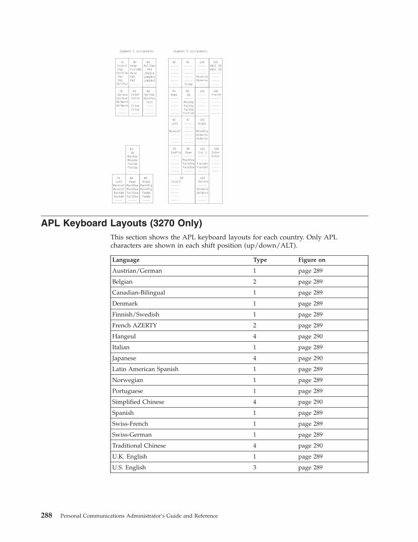
Segment C assignment: Segment D assignment:
Insert
Delete
HomeFieldMkRulePA2PA2-----
UpMarkUpMoveUpFastUpFastUp-----
DownMarkDowMoveDowFastDowFastDow-----
LeftMarkLefMoveLefBackWdBackWd-----
RightMarkRigMoveRigFwdWdFwdWd-----
------------------------------
ANSI 2DANSI 2D--------------------
-------------------------TrnOp
---------------
-----
ErEOFErFld-----ErInpErInp-----
Home-------------------------
Left-----
MoveLef---------------
------------------------------
Right-----
MoveRigUnderScUnderSc-----
EndFld-------------------------
Insert-------------------------
Delete-----
----------
------------------------------
Esc J----------
-----
Up-----MoveUpFastUpFastUpTrnFldI
Down-----
MoveDowFastDowFastDow-----
FieldHiFieldHi
DelWordDelWord
Field+-------------------------
EnterEnter--------------------
RollDwnPA3
ChgScnJumpNxtJumpNxt-----
RollUpEditPstTest---------------
Dup
EditCut
PA1PA1
EditCop
DelWordDelWord-----
ReverseReverse
EditPst
-----
75
76
80
83
8479 89
90 10595 100
81 91
92 97 102
93
99 104
96
98
101
103
106
108
85
86
APL Keyboard Layouts (3270 Only)This section shows the APL keyboard layouts for each country. Only APLcharacters are shown in each shift position (up/down/ALT).
Language Type Figure on
Austrian/German 1 page 289
Belgian 2 page 289
Canadian-Bilingual 1 page 289
Denmark 1 page 289
Finnish/Swedish 1 page 289
French AZERTY 2 page 289
Hangeul 4 page 290
Italian 1 page 289
Japanese 4 page 290
Latin American Spanish 1 page 289
Norwegian 1 page 289
Portuguese 1 page 289
Simplified Chinese 4 page 290
Spanish 1 page 289
Swiss-French 1 page 289
Swiss-German 1 page 289
Traditional Chinese 4 page 290
U.K. English 1 page 289
U.S. English 3 page 289
288 Personal Communications Administrator’s Guide and Reference
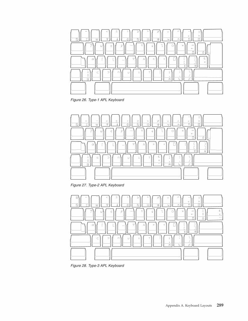
Figure 26. Type-1 APL Keyboard
Figure 27. Type-2 APL Keyboard
Figure 28. Type-3 APL Keyboard
Appendix A. Keyboard Layouts 289

Key Map for Home3270This section shows the position of the following control codes:
NUL (X'00')ESC (X'1B')FS (X'1C')GS (X'1D')RS (X'1E')US (X'1F')
The positions of these control codes are fixed and common for all languages(including U.S. English), regardless of the characters assigned to BASE and UPSHIFT positions of the keys. These control codes are positioned to the CONTROLpositions of the keys shown in Figure 30 through Figure 31 on page 291.
Figure 29. Type-4 APL Keyboard
NUL RS US
ESC GS FS
Figure 30. Common Control Code of Keyboard Core Segment for Non-Japanese Keyboard
290 Personal Communications Administrator’s Guide and Reference

The positions of other control codes vary for each language. These control codesare positioned to the CONTROL position of the associated alphabetic key. Thosecontrol codes and the associated alphabetic characters are as follows.
Table 38. Other Control Code Map of Key Segment B
Control Code Associated Letter
SOH (X'01') a
STX (X'02') b
ETX (X'03') c
EOT (X'04') d
ENQ (X'05') e
ACK (X'06') f
BEL (X'07') g
BS (X'08') h
HT (X'09') i
LF (X'0A') j
VT (X'0B') k
FF (X'0C') l
CR (X'0D') m
SO (X'0E') n
SI (X'0F') o
DLE (X'10') p
DC1(XON) (X'11') q
DC2 (X'12') r
DC3(XOF) (X'13') s
DC4 (X'14') t
NAK (X'15') u
SYN (X'16') v
ETB (X'17') w
CAN (X'18') x
EM (X'19') y
NUL RS US RS
NUL
GS
FS
ESC
Figure 31. Common Control Code of Keyboard Core Segment for Japanese Keyboard
Appendix A. Keyboard Layouts 291
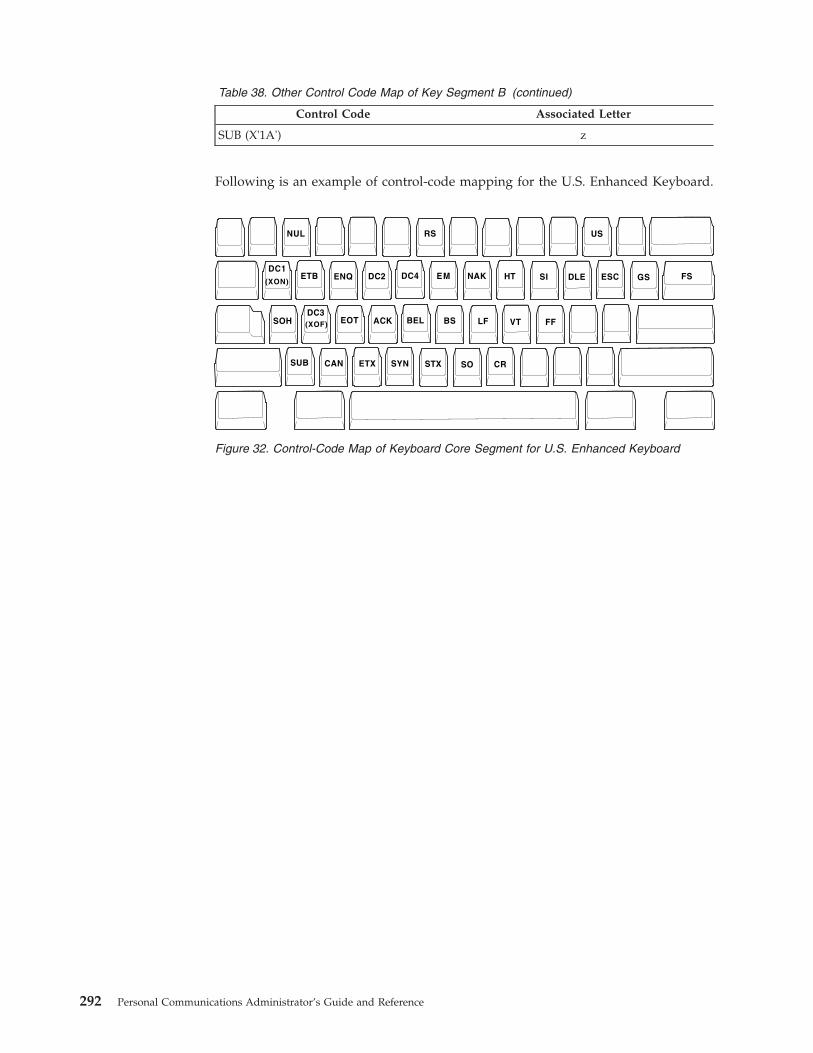
Table 38. Other Control Code Map of Key Segment B (continued)
Control Code Associated Letter
SUB (X'1A') z
Following is an example of control-code mapping for the U.S. Enhanced Keyboard.
NUL RS US
ESC GS FSDC1
ETB ENQ DC2 DC4 EM NAK HT SI DLE
SOHDC3
EOT ACK BEL BS LF VT FF
SUB CAN ETX SYN STX SO CR
(XON)
(XOF)
Figure 32. Control-Code Map of Keyboard Core Segment for U.S. Enhanced Keyboard
292 Personal Communications Administrator’s Guide and Reference

Appendix B. AS/400 Configuration Examples
To connect to an AS/400 system, you need to specify configuration information inthe workstation profile that accurately corresponds to the information specified inthe AS/400 system (referred to as the device description).
For example, the LAN attachment via IEEE 802.2 in the following figure showshow the configuration information specified in the AS/400 workstation profilecorresponds to the configuration information in the AS/400 system.
AS/400 PC400
Network AttributeLocal Network IDLocal Location Name
Line DescriptionLocal Adapter AddressSource Service Access Point (SSAP)
Controller DescriptionController Category (*APPC)Remote Network IDRemote Control PointLAN Remote Adapter Address(PC LAN Adapter Address)
LAN DSAPLAN SSAP
Device DescriptionDevice Category (*APPC)Remote LocationRemote Network ID CodeAPPN available (*YES)
Configure Communication
Session TypeHost Code PageSystem Location Name
Field 1Field 2
PC Location NameField 1Field 2
Workstation IDDevice Description
Device Category (*DSP, *PRT)Device Type (3197/3477, 3812)Device Class (*VRT)Device Format (C1/FC,1)Keyboard Language Type (USB)Character Identifier (697 037)
Configure Link(LAN via IEEE 802.2)
Destination AddressRemote SAP
(Select Advanced)
Local SAP
Figure 33. LAN Attachment via IEEE 802.2
© Copyright IBM Corp. 1989, 2002 293
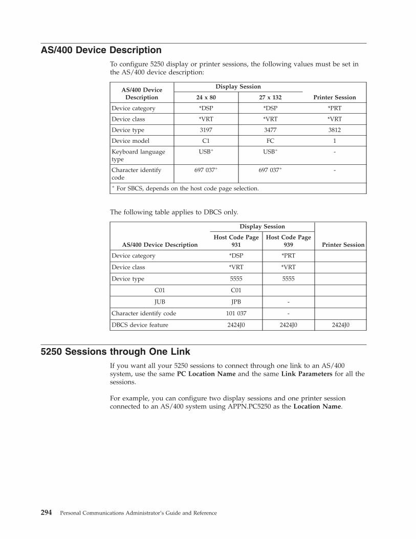
AS/400 Device DescriptionTo configure 5250 display or printer sessions, the following values must be set inthe AS/400 device description:
AS/400 DeviceDescription
Display Session
Printer Session24 x 80 27 x 132
Device category *DSP *DSP *PRT
Device class *VRT *VRT *VRT
Device type 3197 3477 3812
Device model C1 FC 1
Keyboard languagetype
USB+ USB+ -
Character identifycode
697 037+ 697 037+ -
+ For SBCS, depends on the host code page selection.
The following table applies to DBCS only.
AS/400 Device Description
Display Session
Printer SessionHost Code Page
931Host Code Page
939
Device category *DSP *PRT
Device class *VRT *VRT
Device type 5555 5555
C01 C01
JUB JPB -
Character identify code 101 037 -
DBCS device feature 2424J0 2424J0 2424J0
5250 Sessions through One LinkIf you want all your 5250 sessions to connect through one link to an AS/400system, use the same PC Location Name and the same Link Parameters for all thesessions.
For example, you can configure two display sessions and one printer sessionconnected to an AS/400 system using APPN.PC5250 as the Location Name.
294 Personal Communications Administrator’s Guide and Reference

Session A : Session Type : Display(Display) System Location Name : APPN.S7801234
PC Location Name : APPN.PC5250Workstation ID : (not specified)
Session B : Session Type : Display(Display) System Location Name : APPN.S7801234
PC Location Name : APPN.PC5250Workstation ID : (not specified)
Session C : Session Type : Printer(Printer) System Location Name : APPN.S7801234
PC Location Name : APPN.PC5250Workstation ID : PCLOCALP1
In this example, the AS/400 network attributes are:
Local network ID : APPNLocal location : S7801234
TipEnter DSPNETA from a 5250 session to display AS/400 network attributes.
AS/400 System Mode DescriptionPC400 initially uses mode description QPCSUPP on the AS/400 system. If the PCSupport/400 program or Client Access/400 is installed on the AS/400 system,QPCSUPP need not be created. If mode description QPCSUPP does not exist onthe AS/400 system, create the mode description:1. Enter the following command on the command line of the main menu of the
AS/400 system:CRTMODD
The Creating Mode Description panel appears.
Creating Mode Description (CRTMODD)
Type the selected items, and push the Enter key.
Mode Description................. NameMaximum Session.................. 8 1-512Maximum number of interaction.... 8 1-512Number of Local Control Sessions. 4 0-512Number of Pre-joined Sessions.... 0 0-512Inbound Pacing Value............. 7 0-63Outbound Pacing Value............ 7 0-63Maximum Length of Request Unit... *CALC 241-16384, *CALCText Description ................ *BLANK
EndF3=Exit F4=Prompt F5=Reshow F10=Add parameter F12= CancelF13=How to use this panel F24=More key
Appendix B. AS/400 Configuration Examples 295

2. Type the necessary values in each field, according to the following table.
Field Name Input Value
Mode description QPCSUPP
Maximum session 64
Maximum number of interactions 64
Number of local control sessions 0
Number of pre-joined sessions 0
Inbound pacing value 7
Outbound pacing value 7
Maximum length of request unit *CALC
Text description This field is optional
3. After you type all the values, press the Enter key.This completes the creation of the mode description QPCSUPP.
AS/400 Device Description for Twinaxial Attachments (APPC) ExampleIf you want to use a twinaxial (TDLC) attachment, the AS/400 system requires thatyou specify a device description. When the automatic device configurationindicator (QAUTOCFG) is set to ON in the AS/400 system, the device descriptionis created automatically. When the indicator is set to OFF, create the devicedescription, as follows:1. Enter the following command on the command line of the AS/400 system main
menu:CRTDEVDSP
The Creating Device Description (Display) panel appears.
Creating Device Description(Display) (CRTDEVDSP)
Type the selected item, and push Enter key.
Device Description... NameDevice Class.......... *LCL, *RMT, *VRT, *SNPTDevice Type........... 3101, 3151, 3161, 3162...Device Format........ 0, 1, 2, 4, 11, 12, 23...
EndF3=Exit F4=Prompt F5=Reshow F10=Add parameter F12= CancelF13=How to use this panel F24=More key
2. Type the values in each field, according to the following table.
Field Name Input Value
Device description This is an optional field
Device class *LCL
296 Personal Communications Administrator’s Guide and Reference

Field Name Input Value
Device type 5150
Device format 2
3. After you type all values, press the Enter key.The following screen appears:
Creating Device Description(Display) (CRTDEVDSP)
Type the selected item, and push Enter key.
Device Description..........>TWXP0A1 NameDevice Class................>*LCL *LCL, *RMT, *VRT, *SNPTDevice Type.................>5150 3101, 3151, 3161, 3162...Device Format...............>2 0, 1, 2, 4, 11, 12, 23...Port Number................. 0-17Switch Setting.............. 0, 1, 2, 4, 5, 6Online when IPL.............>*YES *YES, *NOController to be attached... NameKeyboard Word Type..........>*SYSVAL *SYSVAL,AGB,AGI,BLI...Text Description............>*BLANK
F3=Exit F4=Prompt F5=Reshow F10=Add parameter F12= CancelF13=How to use this panel F24=More key
4. Type the values for each field, according to the following table.
Field Name Input Value
Port number Number of the port to be attached
Switch setting Device address
Controller to be attached Descriptive name of the controller to be attached
Keyboard word type USB1
1 Depends on the host code page selection.
5. After you enter all the values, press the Enter key.This completes the creation of the device description for the twinaxialattachment.
AS/400 Device Description for Asynchronous Attachment ExampleIf you want to use an asynchronous dial attachment, the AS/400 system requiresthat you specify configuration parameters for the controller/line/devices to beused.
The following sample is a typical configuration on the AS/400 system for anasynchronous dialed connection through an ASCII Workstation Controller.1. Enter the following command on the command line of the AS/400 system main
menu:WRKCFGSTS *CTL CTL03
where CTL03 is the name of your controller.
The Work with Configuration Status panel appears.
Appendix B. AS/400 Configuration Examples 297

Work with Configuration Status
Position to . . . . . _____________ Starting characters
Type options, press Enter1=Vary on 2=Vary off 5=Work with job 8=Work with description9-Display mode status ...
Opt Description Status -------------Job--------------8_ CTL03 ACTIVE__ ADLCTST VARY ON PENDING__ ASYNC VARY ON PENDING__ ASYNCD VARY ON PENDING__ EZASYNC VARY ON PENDING__ ASYNCP0 VARY ON PENDING__ ASYNRTR ACTIVE
BOTTOMParameters or command===>
F3=Exit F4=Prompt F12=Cancel F23=More options F24=More keys
2. Enter 8 in the Opt field to work with the controller description for CTL03.The Work with Controller Descriptions panel appears.
Work with Controller Descriptions
Position to . . . . . _____________ Starting characters
Type options, press Enter2=Change 3=Copy 4=Delete 5=Display 6=Print 7=Rename8=Work with status 9=Retrieve source 12=Print device addresses
Opt Controller Type Text2_ CTL03 6141 CREATED BY AUTO-CONFIGURATION
BOTTOMParameters or command===>F3=Exit F4=Prompt F5=Refresh F6=Create F9=Retrieve F12=CancelF14=Work with status
3. Enter 2 in the Opt field to change the controller description for CTL03.The Change Controller Description panel appears.
298 Personal Communications Administrator’s Guide and Reference

Change Ctl Desc (local WS) (CHGCTLLWS)
Controller Description . . . . . . : CTL03Option . . . . . . . . . . . . . . : *BASICCategory of controller . . . . . . : *LWS
Controller type . . . . . . . . . : 6141Controller model . . . . . . . . . : 1Resource name . . . . . . . . . . : CTL03TDLC line . . . . . . . . . . . . : QTDL429000Online at IPL . . . . . . . . . . : *YESAuto-configuration controller . . : *YESText . . . . . . . . . . . . . . . : CREATED BY AUTO-CONFIGURATIONDevice wait timer . . . . . . . . : 10
Press Enter to continue.===>
BOTTOMF3=Exit F4=Prompt F5=Refresh F12=Cancel F13=How to use this displayF24=More keys
4. Type the values in each field, according to the following table.
Field Name Input Value
Controller description CTL03
Resource name CTL03
Online at IPL *YES
Device wait timer 10
Auto-configuration controller *YES
Text description This field is optional
The Work with Controller Descriptions panel appears.
Work with Controller Descriptions
Position to . . . . . _____________ Starting characters
Type options, press Enter2=Change 3=Copy 4=Delete 5=Display 6=Print 7=Rename8=Work with status 9=Retrieve source 12=Print device addresses
Opt Controller Type Text8_ CTL03 6141 Created by auto-configuration
BOTTOMParameters or command===>F3=Exit F4=Prompt F5=Refresh F6=Create F9=Retrieve F12=CancelF14=Work with status
5. Enter 8 in the Opt field to work with the configuration status.The Work with Configuration Status panel appears.
Appendix B. AS/400 Configuration Examples 299
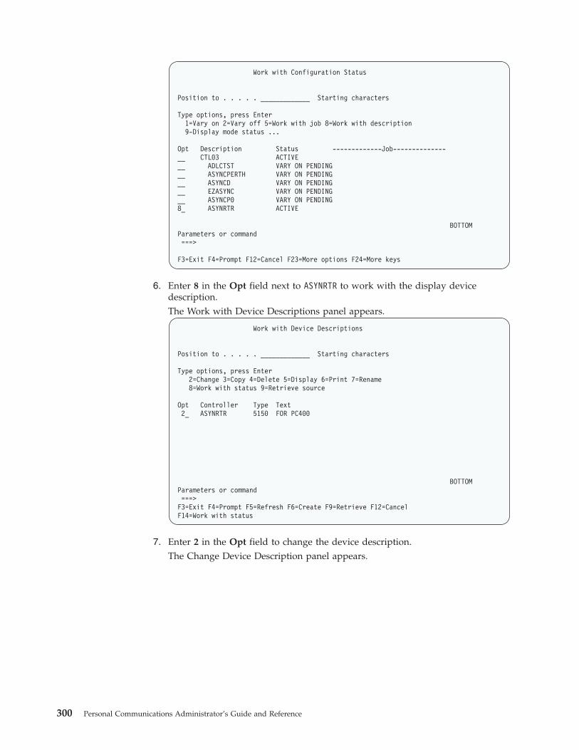
Work with Configuration Status
Position to . . . . . _____________ Starting characters
Type options, press Enter1=Vary on 2=Vary off 5=Work with job 8=Work with description9-Display mode status ...
Opt Description Status -------------Job--------------__ CTL03 ACTIVE__ ADLCTST VARY ON PENDING__ ASYNCPERTH VARY ON PENDING__ ASYNCD VARY ON PENDING__ EZASYNC VARY ON PENDING__ ASYNCP0 VARY ON PENDING8_ ASYNRTR ACTIVE
BOTTOMParameters or command===>
F3=Exit F4=Prompt F12=Cancel F23=More options F24=More keys
6. Enter 8 in the Opt field next to ASYNRTR to work with the display devicedescription.The Work with Device Descriptions panel appears.
Work with Device Descriptions
Position to . . . . . _____________ Starting characters
Type options, press Enter2=Change 3=Copy 4=Delete 5=Display 6=Print 7=Rename8=Work with status 9=Retrieve source
Opt Controller Type Text2_ ASYNRTR 5150 FOR PC400
BOTTOMParameters or command===>F3=Exit F4=Prompt F5=Refresh F6=Create F9=Retrieve F12=CancelF14=Work with status
7. Enter 2 in the Opt field to change the device description.The Change Device Description panel appears.
300 Personal Communications Administrator’s Guide and Reference

Change Device Desc (Display) (CHGDEVDSP)
Type choices, press Enter.
Device description . . . . . . . . > ASYNRTR NamePort number . . . . . . . . . . . 4 0-17, *SAMESwitch setting . . . . . . . . . . 0 0-6, *SAMEOnline at IPL . . . . . . . . . . *YES *SAME, *YES, *NOKeyboard language type . . . . . . USI *SAME, *SYSVAL, *NONE, AGB...
Character identifier:Graphic character set . . . . . *KBDTYPE 1-32767, *KBDTYPE, *SYSVAL...Code page . . . . . . . . . . . 1-32767
Allow blinking cursor . . . . . . *YES *SAME, *YES, *NOPrint device . . . . . . . . . . . *SYSVAL Name, *SAME, *SYSVALOutput queue . . . . . . . . . . . *DEV Name, *SAME, *DEV
Library . . . . . . . . . . . . Name, *LIBL, *CURLIBPrinter file . . . . . . . . . . . QSYSPRT Name, *SAME
Library . . . . . . . . . . . . *LIBL Name, *LIBL, *CURLIBMore...
Press Enter to continue.===>F3=Exit F4=Prompt F5=Refresh F10=Additional parameters F12=CancelF13=How to use this display F24=More keys
This completes the creation of the controller and display device descriptions foran asynchronous dial attachment.
AS/400 VT Asynchronous Attachment ExampleThe following sample is a typical configuration on the AS/400 system for a VTasynchronous dialed connection through an ASCII Workstation Controller. Formore details on AS/400 for VT asynchronous attachments, refer to AS/400 ASCIIWorkstation Reference (SA41-3130-00).1. Enter the following command on the command line of the AS/400 system main
menu:CRTDEVDSP
The Create Device Description panel appears, in a first and second screen, asshown for the configuration of a VT100 device in the following screens. Whenfilling in the panel, make sure that the name of the attached controller(arbitrarily shown as CTL05 here) matches the name of the twinaxial controllerconfigured on your AS/400.
Appendix B. AS/400 Configuration Examples 301

Create Device Desc (Display) (CRTDEVDSP)
Type choices, press Enter.
Device description . . . . . . . > VT100 NameDevice class . . . . . . . . . . > *LCL *LCL, *RMT, *VRT, *SNPTDevice type . . . . . . . . . . > V100 3101, 3151, 3161, 3162...Device model . . . . . . . . . . > *ASCII 0, 1, 2, 4, 5, 12, 23 ...Emulated twinaxial device . . . > *TYPE 3196A2, 3197D2, *TYPEPort number . . . . . . . . . . > 1 0-17Emulating ASCII device . . . . . > *NO *NO, *YESPhysical attachment . . . . . . > *MODEM *DIRECT, *PTT, *MODEM...Online at IPL . . . . . . . . . > *YES *YES, *NOAttached controller . . . . . . > CTL05 NameKeyboard language type . . . . . > USB *SYSVAL, AGB, AGI, ALI...Inactivity timer . . . . . . . . > *NOMAX 1-30, *ATTACH, *NOMAX...Line speed . . . . . . . . . . . > 19200 *TYPE, *CALC, 150, 300...Word length . . . . . . . . . . > 8 *TYPE, *CALC, 7, 8Type of parity . . . . . . . . . > *NONE *TYPE, *CALC, *EVEN, *ODD...Stop bits . . . . . . . . . . . > 2 *TYPE, 1, 2
More...F3=Exit F4=Prompt F5=Refresh F10=Additional parameters F12=CancelF13=How to use this display F24=More keys
Create Device Desc (Display) (CRTDEVDSP)
Type choices, press Enter.
Text ’description’ . . . . . . . > ’dec vt100 device description test’
Additional ParametersCharacter identifier:
Graphic character set . . . . > *KBDTYPE 1-32767, *SYSVAL, *KBDTYPECode page . . . . . . . . . . 1-32767
Print device . . . . . . . . . . > *SYSVAL Name, *SYSVALOutput queue . . . . . . . . . . > *DEV Name, *DEV
Library . . . . . . . . . . . Name, *LIBL, *CURLIBPrinter file . . . . . . . . . . > QSYSPRT Name
Library . . . . . . . . . . . > *LIBL Name, *LIBL, *CURLIB
BottomF3=Exit F4=Prompt F5=Refresh F10=Additional parameters F12=CancelF13=How to use this display F24=More keys
2. For a similar configuration for a VT220:Use the same command, CRTDEVDSP, on the command line of the AS/400system main menu. Again, the same kind of panels appear. You must makesure that the name of the attached controller matches the name of the twinaxialcontroller configured on your AS/400.
302 Personal Communications Administrator’s Guide and Reference
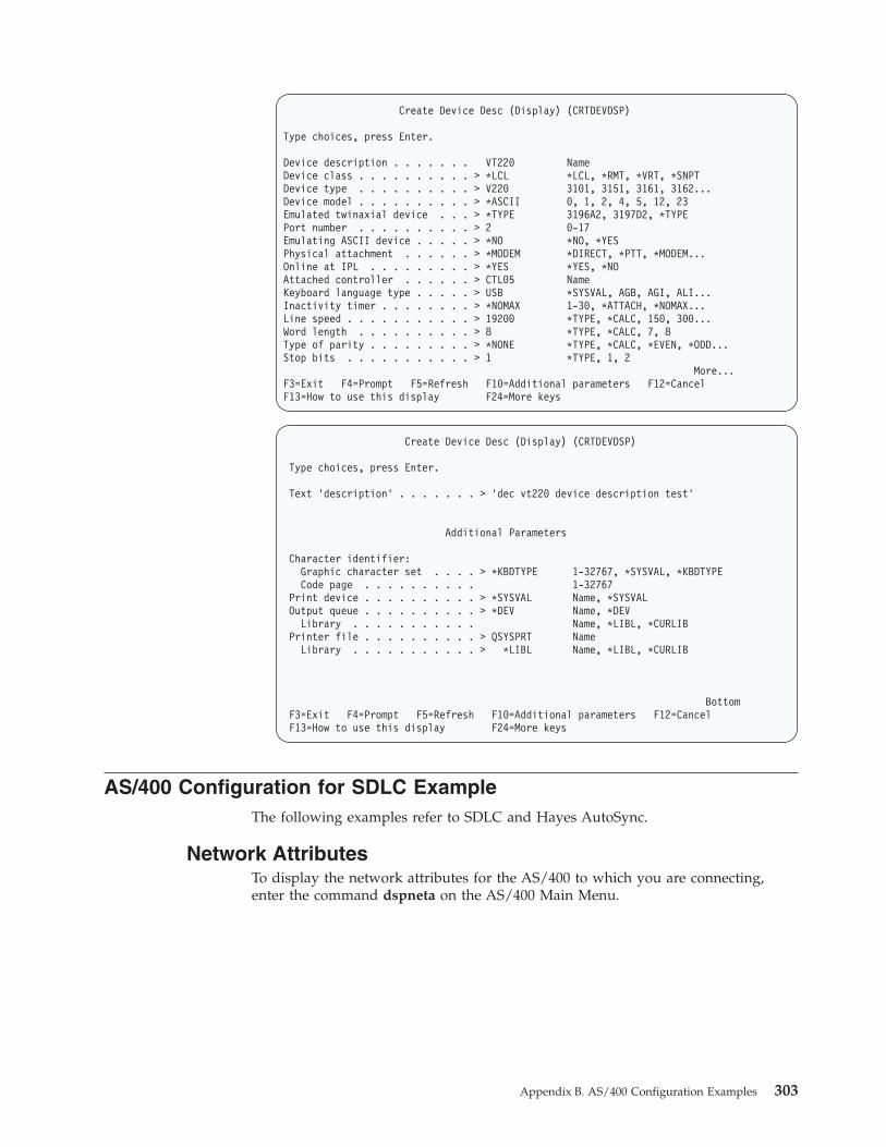
Create Device Desc (Display) (CRTDEVDSP)
Type choices, press Enter.
Device description . . . . . . . VT220 NameDevice class . . . . . . . . . . > *LCL *LCL, *RMT, *VRT, *SNPTDevice type . . . . . . . . . . > V220 3101, 3151, 3161, 3162...Device model . . . . . . . . . . > *ASCII 0, 1, 2, 4, 5, 12, 23Emulated twinaxial device . . . > *TYPE 3196A2, 3197D2, *TYPEPort number . . . . . . . . . . > 2 0-17Emulating ASCII device . . . . . > *NO *NO, *YESPhysical attachment . . . . . . > *MODEM *DIRECT, *PTT, *MODEM...Online at IPL . . . . . . . . . > *YES *YES, *NOAttached controller . . . . . . > CTL05 NameKeyboard language type . . . . . > USB *SYSVAL, AGB, AGI, ALI...Inactivity timer . . . . . . . . > *NOMAX 1-30, *ATTACH, *NOMAX...Line speed . . . . . . . . . . . > 19200 *TYPE, *CALC, 150, 300...Word length . . . . . . . . . . > 8 *TYPE, *CALC, 7, 8Type of parity . . . . . . . . . > *NONE *TYPE, *CALC, *EVEN, *ODD...Stop bits . . . . . . . . . . . > 1 *TYPE, 1, 2
More...F3=Exit F4=Prompt F5=Refresh F10=Additional parameters F12=CancelF13=How to use this display F24=More keys
Create Device Desc (Display) (CRTDEVDSP)
Type choices, press Enter.
Text ’description’ . . . . . . . > ’dec vt220 device description test’
Additional Parameters
Character identifier:Graphic character set . . . . > *KBDTYPE 1-32767, *SYSVAL, *KBDTYPECode page . . . . . . . . . . 1-32767
Print device . . . . . . . . . . > *SYSVAL Name, *SYSVALOutput queue . . . . . . . . . . > *DEV Name, *DEV
Library . . . . . . . . . . . Name, *LIBL, *CURLIBPrinter file . . . . . . . . . . > QSYSPRT Name
Library . . . . . . . . . . . > *LIBL Name, *LIBL, *CURLIB
BottomF3=Exit F4=Prompt F5=Refresh F10=Additional parameters F12=CancelF13=How to use this display F24=More keys
AS/400 Configuration for SDLC ExampleThe following examples refer to SDLC and Hayes AutoSync.
Network AttributesTo display the network attributes for the AS/400 to which you are connecting,enter the command dspneta on the AS/400 Main Menu.
Appendix B. AS/400 Configuration Examples 303
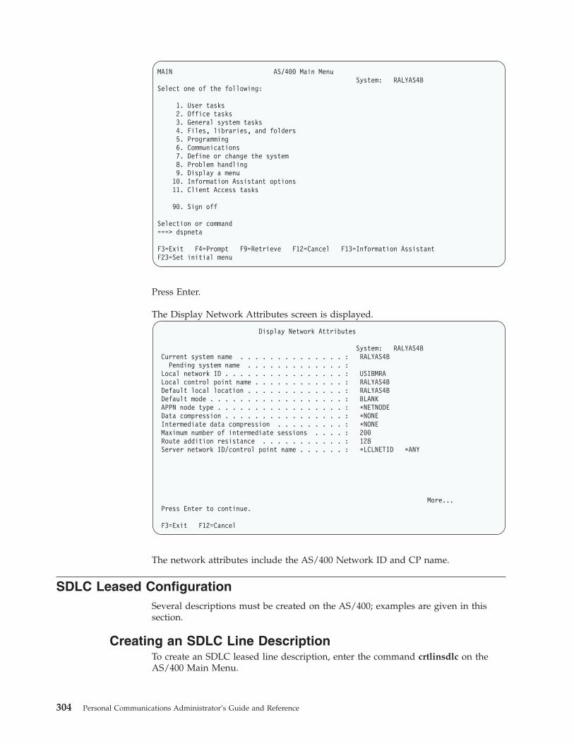
MAIN AS/400 Main MenuSystem: RALYAS4B
Select one of the following:
1. User tasks2. Office tasks3. General system tasks4. Files, libraries, and folders5. Programming6. Communications7. Define or change the system8. Problem handling9. Display a menu10. Information Assistant options11. Client Access tasks
90. Sign off
Selection or command===> dspneta
F3=Exit F4=Prompt F9=Retrieve F12=Cancel F13=Information AssistantF23=Set initial menu
Press Enter.
The Display Network Attributes screen is displayed.
Display Network Attributes
System: RALYAS4BCurrent system name . . . . . . . . . . . . . . : RALYAS4B
Pending system name . . . . . . . . . . . . . :Local network ID . . . . . . . . . . . . . . . . : USIBMRALocal control point name . . . . . . . . . . . . : RALYAS4BDefault local location . . . . . . . . . . . . . : RALYAS4BDefault mode . . . . . . . . . . . . . . . . . . : BLANKAPPN node type . . . . . . . . . . . . . . . . . : *NETNODEData compression . . . . . . . . . . . . . . . . : *NONEIntermediate data compression . . . . . . . . . : *NONEMaximum number of intermediate sessions . . . . : 200Route addition resistance . . . . . . . . . . . : 128Server network ID/control point name . . . . . . : *LCLNETID *ANY
More...Press Enter to continue.
F3=Exit F12=Cancel
The network attributes include the AS/400 Network ID and CP name.
SDLC Leased ConfigurationSeveral descriptions must be created on the AS/400; examples are given in thissection.
Creating an SDLC Line DescriptionTo create an SDLC leased line description, enter the command crtlinsdlc on theAS/400 Main Menu.
304 Personal Communications Administrator’s Guide and Reference

MAIN AS/400 Main MenuSystem: RALYAS4B
Select one of the following:
1. User tasks2. Office tasks3. General system tasks4. Files, libraries, and folders5. Programming6. Communications7. Define or change the system8. Problem handling9. Display a menu10. Information Assistant options11. Client Access tasks
90. Sign off
Selection or command===> crtlinsdlc
F3=Exit F4=Prompt F9=Retrieve F12=Cancel F13=Information AssistantF23=Set initial menu
Press F4 (Prompt).
The Create LIne Description panel is displayed. Enter the values for eachparameter on the panel.
Create Line Desc (SDLC) (CRTLINSDLC)
Type choices, press Enter.
Line description . . . . . . . . > PCOMMSDLCL NameResource names . . . . . . . . . > LIN021 Name
+ for more valuesOnline at IPL . . . . . . . . . *YES *YES, *NOData link role . . . . . . . . . *NEG *NEG, *PRI, *SECPhysical interface . . . . . . . *RS232V24 *RS232V24, *V35, *X21, ...Connection type . . . . . . . . *NONSWTPP *NONSWTPP, *SWTPP, *MP, *SHMSwitched network backup . . . . *NO *NO, *YESExchange identifier . . . . . . *SYSGEN 05600000-056FFFFF, *SYSGENNRZI data encoding . . . . . . . *YES *YES, *NOLine speed . . . . . . . . . . . 9600 600, 1200, 2400, 4800...Modem type supported . . . . . . *NORMAL *NORMAL, *V54, *IBMWRAP...Maximum frame size . . . . . . . 521 265, 521, 1033, 2057Duplex . . . . . . . . . . . . . *HALF *HALF, *FULLInactivity timer . . . . . . . . 300 *NOMAX, 150-4200 (0.1 sec)Poll response delay . . . . . . 0 0-2048 (0.0001 seconds)
More...F3=Exit F4=Prompt F5=Refresh F12=Cancel F13=How to use this displayF24=More keys
Appendix B. AS/400 Configuration Examples 305

Create Line Desc (SDLC) (CRTLINSDLC)
Type choices, press Enter.
Nonproductive receive timer . . 320 160-4200 (0.1 seconds)Idle timer . . . . . . . . . . . 30 5-300 (0.1 seconds)Connect poll timer . . . . . . . 30 2-300 (0.1 seconds)Poll cycle pause . . . . . . . . 0 0-2048 (0.0001 seconds)Frame retry . . . . . . . . . . 7 0-64Text ’description’ . . . . . . . PCOMM SDLC leased line
Additional Parameters
Attached nonswitched ctls . . . Name+ for more values
Modem data rate select . . . . . *FULL *FULL, *HALFError threshold level . . . . . *OFF *OFF, *MIN, *MED, *MAXModulus . . . . . . . . . . . . 8 8, 128Maximum outstanding frames . . . 7 1-28
More...F3=Exit F4=Prompt F5=Refresh F12=Cancel F13=How to use this displayF24=More keys
Press Enter to save the line description pcommsdlcl.
SDLC Controller DescriptionTo create the SDLC controller description for the line PCOMMSDLCL, entercrtctlappc on the AS/400 Main Menu.
MAIN AS/400 Main MenuSystem: RALYAS4B
Select one of the following:
1. User tasks2. Office tasks3. General system tasks4. Files, libraries, and folders5. Programming6. Communications7. Define or change the system8. Problem handling9. Display a menu10. Information Assistant options11. Client Access tasks
90. Sign off
Selection or command===> crtctlappc
F3=Exit F4=Prompt F9=Retrieve F12=Cancel F13=Information AssistantF23=Set initial menu
Press F4 (Prompt). The Create Controller Description panel is displayed. Entervalues for each parameter on the following two panels.
306 Personal Communications Administrator’s Guide and Reference
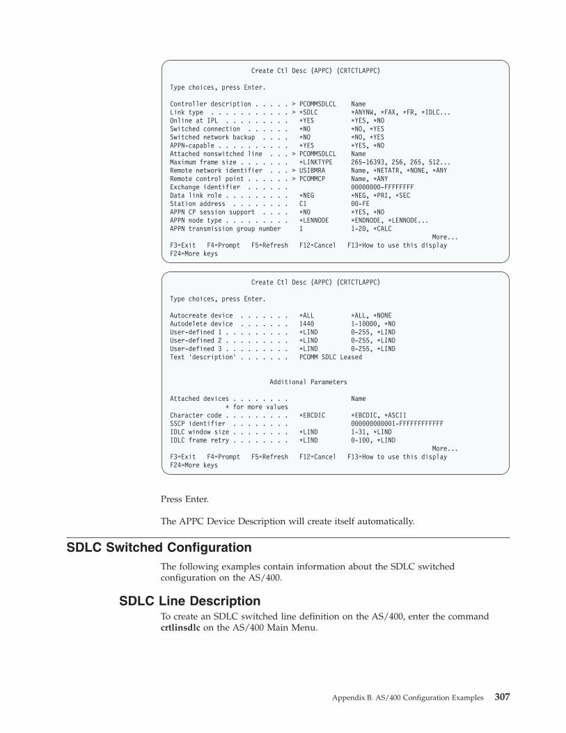
Create Ctl Desc (APPC) (CRTCTLAPPC)
Type choices, press Enter.
Controller description . . . . . > PCOMMSDLCL NameLink type . . . . . . . . . . . > *SDLC *ANYNW, *FAX, *FR, *IDLC...Online at IPL . . . . . . . . . *YES *YES, *NOSwitched connection . . . . . . *NO *NO, *YESSwitched network backup . . . . *NO *NO, *YESAPPN-capable . . . . . . . . . . *YES *YES, *NOAttached nonswitched line . . . > PCOMMSDLCL NameMaximum frame size . . . . . . . *LINKTYPE 265-16393, 256, 265, 512...Remote network identifier . . . > USIBMRA Name, *NETATR, *NONE, *ANYRemote control point . . . . . . > PCOMMCP Name, *ANYExchange identifier . . . . . . 00000000-FFFFFFFFData link role . . . . . . . . . *NEG *NEG, *PRI, *SECStation address . . . . . . . . C1 00-FEAPPN CP session support . . . . *NO *YES, *NOAPPN node type . . . . . . . . . *LENNODE *ENDNODE, *LENNODE...APPN transmission group number 1 1-20, *CALC
More...F3=Exit F4=Prompt F5=Refresh F12=Cancel F13=How to use this displayF24=More keys
Create Ctl Desc (APPC) (CRTCTLAPPC)
Type choices, press Enter.
Autocreate device . . . . . . . *ALL *ALL, *NONEAutodelete device . . . . . . . 1440 1-10000, *NOUser-defined 1 . . . . . . . . . *LIND 0-255, *LINDUser-defined 2 . . . . . . . . . *LIND 0-255, *LINDUser-defined 3 . . . . . . . . . *LIND 0-255, *LINDText ’description’ . . . . . . . PCOMM SDLC Leased
Additional Parameters
Attached devices . . . . . . . . Name+ for more values
Character code . . . . . . . . . *EBCDIC *EBCDIC, *ASCIISSCP identifier . . . . . . . . 000000000001-FFFFFFFFFFFFIDLC window size . . . . . . . . *LIND 1-31, *LINDIDLC frame retry . . . . . . . . *LIND 0-100, *LIND
More...F3=Exit F4=Prompt F5=Refresh F12=Cancel F13=How to use this displayF24=More keys
Press Enter.
The APPC Device Description will create itself automatically.
SDLC Switched ConfigurationThe following examples contain information about the SDLC switchedconfiguration on the AS/400.
SDLC Line DescriptionTo create an SDLC switched line definition on the AS/400, enter the commandcrtlinsdlc on the AS/400 Main Menu.
Appendix B. AS/400 Configuration Examples 307

MAIN AS/400 Main MenuSystem: RALYAS4B
Select one of the following:
1. User tasks2. Office tasks3. General system tasks4. Files, libraries, and folders5. Programming6. Communications7. Define or change the system8. Problem handling9. Display a menu10. Information Assistant options11. Client Access tasks
90. Sign off
Selection or command===> crtlinsdlc
F3=Exit F4=Prompt F9=Retrieve F12=Cancel F13=Information AssistantF23=Set initial menu
Press F4 (Prompt).
The Create Ctl Description panel is displayed. Enter values for each parameter onthe panel.
Create Line Desc (SDLC) (CRTLINSDLC)
Type choices, press Enter.
Line description . . . . . . . . > PCOMSDLCSW NameResource names . . . . . . . . . > LIN051 Name
+ for more valuesOnline at IPL . . . . . . . . . *YES *YES, *NOData link role . . . . . . . . . > *PRI *NEG, *PRI, *SECPhysical interface . . . . . . . *RS232V24 *RS232V24, *V35, *X21, ...Connection type . . . . . . . . > *SWTPP *NONSWTPP, *SWTPP, *MP, *SHMVary on wait . . . . . . . . . . *NOWAIT *NOWAIT, 15-180 (1 second)Autocall unit . . . . . . . . . *NO *NO, *YESExchange identifier . . . . . . *SYSGEN 05600000-056FFFFF, *SYSGENNRZI data encoding . . . . . . . *YES *YES, *NOLine speed . . . . . . . . . . . 9600 600, 1200, 2400, 4800...Modem type supported . . . . . . *NORMAL *NORMAL, *V54, *IBMWRAP...Switched connection type . . . . *BOTH *BOTH, *ANS, *DIALAutoanswer . . . . . . . . . . . *YES *YES, *NOAutodial . . . . . . . . . . . . *NO *NO, *YES
More...F3=Exit F4=Prompt F5=Refresh F12=Cancel F13=How to use this displayF24=More keys
308 Personal Communications Administrator’s Guide and Reference

Create Line Desc (SDLC) (CRTLINSDLC)
Type choices, press Enter.
Calling number . . . . . . . . . *NONEConnect poll retry . . . . . . . 7 0-64Maximum frame size . . . . . . . 521 265, 521, 1033, 2057Duplex . . . . . . . . . . . . . *HALF *HALF, *FULLNonproductive receive timer . . 320 160-4200 (0.1 seconds)Idle timer . . . . . . . . . . . 30 5-300 (0.1 seconds)Connect poll timer . . . . . . . 30 2-300 (0.1 seconds)Poll cycle pause . . . . . . . . 0 0-2048 (0.0001 seconds)Frame retry . . . . . . . . . . 7 0-64Data Set Ready drop timer . . . 6 3-60 (seconds)Autoanswer type . . . . . . . . *DTR *DTR, *CDSTLRemote answer timer . . . . . . 60 30, 35, 40, 45 (seconds)...Text ’description’ . . . . . . . PCOMM SDLC switched line
More...F3=Exit F4=Prompt F5=Refresh F12=Cancel F13=How to use this displayF24=More keys
Press Enter to save the description pcomsdlcsw.
SDLC Controller DescriptionTo create the controller description for the switched SDLC line, enter crtctlappc onthe AS/400 Main Menu.
MAIN AS/400 Main MenuSystem: RALYAS4B
Select one of the following:
1. User tasks2. Office tasks3. General system tasks4. Files, libraries, and folders5. Programming6. Communications7. Define or change the system8. Problem handling9. Display a menu10. Information Assistant options11. Client Access tasks
90. Sign off
Selection or command===> crtctlappc
F3=Exit F4=Prompt F9=Retrieve F12=Cancel F13=Information AssistantF23=Set initial menu
Press F4 (Prompt).
The Create Controller Description panel is displayed. Enter values for eachparameter on the panel.
Appendix B. AS/400 Configuration Examples 309
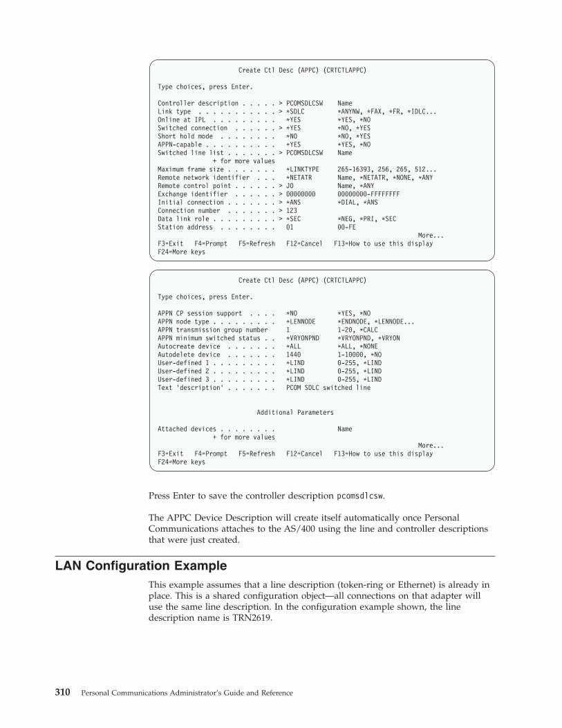
Create Ctl Desc (APPC) (CRTCTLAPPC)
Type choices, press Enter.
Controller description . . . . . > PCOMSDLCSW NameLink type . . . . . . . . . . . > *SDLC *ANYNW, *FAX, *FR, *IDLC...Online at IPL . . . . . . . . . *YES *YES, *NOSwitched connection . . . . . . > *YES *NO, *YESShort hold mode . . . . . . . . *NO *NO, *YESAPPN-capable . . . . . . . . . . *YES *YES, *NOSwitched line list . . . . . . . > PCOMSDLCSW Name
+ for more valuesMaximum frame size . . . . . . . *LINKTYPE 265-16393, 256, 265, 512...Remote network identifier . . . *NETATR Name, *NETATR, *NONE, *ANYRemote control point . . . . . . > JO Name, *ANYExchange identifier . . . . . . > 00000000 00000000-FFFFFFFFInitial connection . . . . . . . > *ANS *DIAL, *ANSConnection number . . . . . . . > 123Data link role . . . . . . . . . > *SEC *NEG, *PRI, *SECStation address . . . . . . . . 01 00-FE
More...F3=Exit F4=Prompt F5=Refresh F12=Cancel F13=How to use this displayF24=More keys
Create Ctl Desc (APPC) (CRTCTLAPPC)
Type choices, press Enter.
APPN CP session support . . . . *NO *YES, *NOAPPN node type . . . . . . . . . *LENNODE *ENDNODE, *LENNODE...APPN transmission group number 1 1-20, *CALCAPPN minimum switched status . . *VRYONPND *VRYONPND, *VRYONAutocreate device . . . . . . . *ALL *ALL, *NONEAutodelete device . . . . . . . 1440 1-10000, *NOUser-defined 1 . . . . . . . . . *LIND 0-255, *LINDUser-defined 2 . . . . . . . . . *LIND 0-255, *LINDUser-defined 3 . . . . . . . . . *LIND 0-255, *LINDText ’description’ . . . . . . . PCOM SDLC switched line
Additional Parameters
Attached devices . . . . . . . . Name+ for more values
More...F3=Exit F4=Prompt F5=Refresh F12=Cancel F13=How to use this displayF24=More keys
Press Enter to save the controller description pcomsdlcsw.
The APPC Device Description will create itself automatically once PersonalCommunications attaches to the AS/400 using the line and controller descriptionsthat were just created.
LAN Configuration ExampleThis example assumes that a line description (token-ring or Ethernet) is already inplace. This is a shared configuration object—all connections on that adapter willuse the same line description. In the configuration example shown, the linedescription name is TRN2619.
310 Personal Communications Administrator’s Guide and Reference

LAN Controller DescriptionThe normal method would be to let the APPC controller create itself automatically.However, if preferred, the following command can be used to manually create theAPPC controller.
To create a LAN controller description, enter crtctlappc on the AS/400 Main Menu.
MAIN AS/400 Main MenuSystem: RALYAS4B
Select one of the following:
1. User tasks2. Office tasks3. General system tasks4. Files, libraries, and folders5. Programming6. Communications7. Define or change the system8. Problem handling9. Display a menu10. Information Assistant options11. Client Access tasks
90. Sign off
Selection or command===> crtctlappc
F3=Exit F4=Prompt F9=Retrieve F12=Cancel F13=Information AssistantF23=Set initial menu
Press F4 (Prompt). The Create Controller Description panel will be displayed.
Enter values for each parameter on the panel.
Create Ctl Desc (APPC) (CRTCTLAPPC)
Controller description . . . . . > PCOMMLAN NameLink type . . . . . . . . . . . > *LAN *ANYNW, *FAX, *FR, *IDLC...Online at IPL . . . . . . . . . *YES *YES, *NOAPPN-capable . . . . . . . . . . *YES *YES, *NOSwitched line list . . . . . . . > TRN2619 Name
+ for more valuesMaximum frame size . . . . . . . *LINKTYPE 265-16393, 256, 265, 512...Remote network identifier . . . *NETATR Name, *NETATR, *NONE, *ANYRemote control point . . . . . . > PEPE Name, *ANYExchange identifier . . . . . . 00000000-FFFFFFFFInitial connection . . . . . . . *DIAL *DIAL, *ANSDial initiation . . . . . . . . *LINKTYPE *LINKTYPE, *IMMED, *DELAYLAN remote adapter address . . . 400052005109 000000000001-FFFFFFFFFFFFAPPN CP session support . . . . *NO *YES, *NOAPPN node type . . . . . . . . . *LENNODE *ENDNODE, *LENNODE...APPN/HPR capable . . . . . . . . *YES *YES, *NO
More...F3=Exit F4=Prompt F5=Refresh F12=Cancel F13=How to use this displayF24=More keys
Appendix B. AS/400 Configuration Examples 311

Create Ctl Desc (APPC) (CRTCTLAPPC)
Type choices, press Enter.
APPN transmission group number 1 1-20, *CALCAPPN minimum switched status . . *VRYONPND *VRYONPND, *VRYONAutocreate device . . . . . . . *ALL *ALL, *NONEAutodelete device . . . . . . . 1440 1-10000, *NOUser-defined 1 . . . . . . . . . *LIND 0-255, *LINDUser-defined 2 . . . . . . . . . *LIND 0-255, *LINDUser-defined 3 . . . . . . . . . *LIND 0-255, *LINDModel controller description . . *NO *NO, *YESText ’description’ . . . . . . . PCOMM token-ring
BottomF3=Exit F4=Prompt F5=Refresh F10=Additional parameters F12=CancelF13=How to use this display F24=More keys
Press Enter to save the controller description pcommlan.
The APPC Device Description will create itself automatically. PersonalCommunications attaches to the AS/400 using the controller description that wasjust created.
312 Personal Communications Administrator’s Guide and Reference

Appendix C. Host Code Page Tables
The following tables show the host code page for each country.
© Copyright IBM Corp. 1989, 2002 313

Host Code Page 037-1/697-1 Brazil, Canada, Netherlands, Portugal,U.S., and 037/1175 Traditional Chinese
The column indicates the first digit and the row indicates the second digit.
Brazil, Canada, Netherlands, Portugal, U.S., Trad. Chinese
314 Personal Communications Administrator’s Guide and Reference

Host Code Page 273-1/697-1 Austria, GermanyThe column indicates the first digit and the row indicates the second digit.
Austria, Germany
Appendix C. Host Code Page Tables 315

Host Code Page 275-1/697-1 BrazilThe column indicates the first digit and the row indicates the second digit.
Brazil
316 Personal Communications Administrator’s Guide and Reference

Host Code Page 277-1/697-1 Denmark, NorwayThe column indicates the first digit and the row indicates the second digit.
Denmark, Norway
Appendix C. Host Code Page Tables 317

Host Code Page 278-1/697-1 Finland, SwedenThe column indicates the first digit and the row indicates the second digit.
Finland, Sweden
318 Personal Communications Administrator’s Guide and Reference

Host Code Page 280-1/697-1 ItalyThe column indicates the first digit and the row indicates the second digit.
Italy
Appendix C. Host Code Page Tables 319

Host Code Page 284-1/697-1 Latin America, SpainThe column indicates the first digit and the row indicates the second digit.
Spain, Latin America
320 Personal Communications Administrator’s Guide and Reference

Host Code Page 285-1/697-1 United KingdomThe column indicates the first digit and the row indicates the second digit.
United Kingdom
Appendix C. Host Code Page Tables 321

Host Code Page 290 Japan (Katakana) ExtendedThe column indicates the first digit and the row indicates the second digit.
Japan (Katakana) Extended
322 Personal Communications Administrator’s Guide and Reference

Host Code Page 297-1/697-1 FranceThe column indicates the first digit and the row indicates the second digit.
France
Appendix C. Host Code Page Tables 323

Host Code Page 420 Arabic BilingualThe column indicates the first digit and the row indicates the second digit.
Arabic
324 Personal Communications Administrator’s Guide and Reference

Host Code Page 424/941 Israel (Hebrew - Bulletin Code)The column indicates the first digit and the row indicates the second digit.
Israel (Hebrew)
Appendix C. Host Code Page Tables 325

Host Code Page 500-1/697-1 InternationalThe column indicates the first digit and the row indicates the second digit.
International
326 Personal Communications Administrator’s Guide and Reference

Host Code Page 803 Israel (Hebrew - Old Code)The column indicates the first digit and the row indicates the second digit.
Israel (Hebrew)
Appendix C. Host Code Page Tables 327

Host Code Page 833/1173 HangeulThe column indicates the first digit and the row indicates the second digit.
Hangeul
328 Personal Communications Administrator’s Guide and Reference

Host Code Page 836/1174 Simplified ChineseThe column indicates the first digit and the row indicates the second digit.
Simplified Chinese
Appendix C. Host Code Page Tables 329

Host Code Page 870/959 Latin 2 - EBCDIC MultilingualThe column indicates the first digit and the row indicates the second digit.
Latin 2
330 Personal Communications Administrator’s Guide and Reference

Host Code Page 871-1/697-1 IcelandThe column indicates the first digit and the row indicates the second digit.
Iceland
Appendix C. Host Code Page Tables 331

Host Code Page 875 GreeceThe column indicates the first digit and the row indicates the second digit.
Greece
332 Personal Communications Administrator’s Guide and Reference

Host Code Page 924-1/1353-1 InternationalThe column indicates the first digit and the row indicates the second digit.
International
Appendix C. Host Code Page Tables 333

Host Code Page 1025/1150 CyrillicThe column indicates the first digit, and the row indicates the second digit. If thiscode page is not used with a Cyrillic host machine, certain characters might notdisplay properly.
Cyrillic
334 Personal Communications Administrator’s Guide and Reference

Host Code Page 1026/1152 Latin 5 - TurkeyThe column indicates the first digit, and the row indicates the second digit.
Latin 5, Turkey
Appendix C. Host Code Page Tables 335

Host Code Page 1027/1172 Japan (Latin) ExtendedThe column indicates the first digit and the row indicates the second digit.
Japan (Latin) Extended
336 Personal Communications Administrator’s Guide and Reference

Host Code Page 1047/103 Latin 1 (Open Systems)The column indicates the first digit and the row indicates the second digit.
Latin 1
Appendix C. Host Code Page Tables 337

Host Code Page 1112/1035 Latvia, LithuaniaThe column indicates the first digit and the row indicates the second digit.
Latvia, Lithuania
338 Personal Communications Administrator’s Guide and Reference

Host Code Page 1122/1037 EstoniaThe column indicates the first digit and the row indicates the second digit.
Estonia
Appendix C. Host Code Page Tables 339

Host Code Page 1123 UkraineThe column indicates the first digit and the row indicates the second digit.
Ukraine
340 Personal Communications Administrator’s Guide and Reference
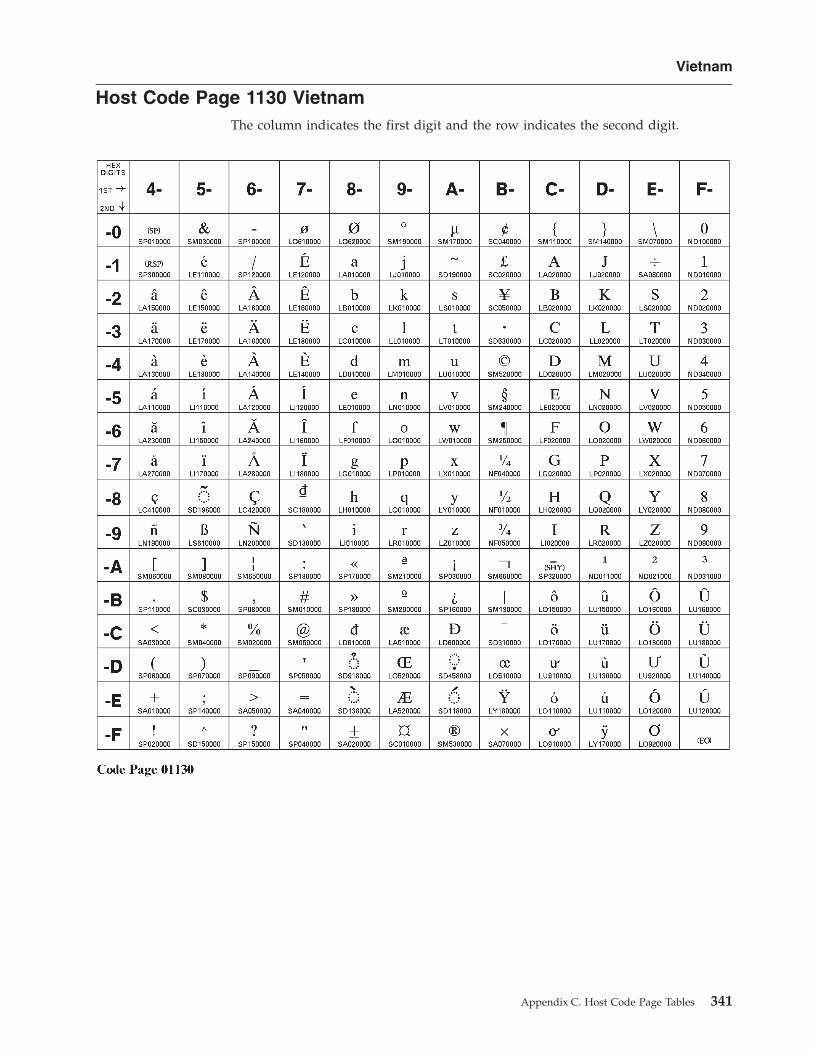
Host Code Page 1130 VietnamThe column indicates the first digit and the row indicates the second digit.
Vietnam
Appendix C. Host Code Page Tables 341

Host Code Page 1132 LaosThe column indicates the first digit and the row indicates the second digit.
Laos
342 Personal Communications Administrator’s Guide and Reference

Host Code Page 1137 IndiaThe column indicates the first digit and the row indicates the second digit.
India
Appendix C. Host Code Page Tables 343

Host Code Page 1140-1/695-1 Brazil, Canada, Netherlands, Portugal,U.S., and 1140/1175 Traditional Chinese
The column indicates the first digit and the row indicates the second digit.
Brazil, Canada, Netherlands, Portugal, U.S., Trad. Chinese
344 Personal Communications Administrator’s Guide and Reference

Host Code Page 1141-1/695-1 Austria, GermanyThe column indicates the first digit and the row indicates the second digit.
Austria, Germany
Appendix C. Host Code Page Tables 345

Host Code Page 1142-1/695-1 Denmark, NorwayThe column indicates the first digit and the row indicates the second digit.
Denmark, Norway
346 Personal Communications Administrator’s Guide and Reference

Host Code Page 1143-1/695-1 Finland, SwedenThe column indicates the first digit and the row indicates the second digit.
Finland, Sweden
Appendix C. Host Code Page Tables 347

Host Code Page 1144-1/695-1 ItalyThe column indicates the first digit and the row indicates the second digit.
Italy
348 Personal Communications Administrator’s Guide and Reference

Host Code Page 1145-1/695-1 Latin America, SpainThe column indicates the first digit and the row indicates the second digit.
Spain, Latin America
Appendix C. Host Code Page Tables 349

Host Code Page 1146-1/695-1 United KingdomThe column indicates the first digit and the row indicates the second digit.
United Kingdom
350 Personal Communications Administrator’s Guide and Reference

Host Code Page 1147-1/695-1 FranceThe column indicates the first digit and the row indicates the second digit.
France
Appendix C. Host Code Page Tables 351

Host Code Page 1148-1/695-1 InternationalThe column indicates the first digit and the row indicates the second digit.
International
352 Personal Communications Administrator’s Guide and Reference

Host Code Page 1149-1/695-1 IcelandThe column indicates the first digit and the row indicates the second digit.
Iceland
Appendix C. Host Code Page Tables 353

Host Code Page 1153/1375 Latin 2 - EBCDIC MultilingualThe column indicates the first digit and the row indicates the second digit.
Latin 2
354 Personal Communications Administrator’s Guide and Reference

Host Code Page 1154/1381 CyrillicThe column indicates the first digit, and the row indicates the second digit. If thiscode page is not used with a Cyrillic host machine, certain characters might notdisplay properly.
Cyrillic
Appendix C. Host Code Page Tables 355

Host Code Page 1155/1378 Latin 5 - TurkeyThe column indicates the first digit, and the row indicates the second digit.
Latin 5, Turkey
356 Personal Communications Administrator’s Guide and Reference
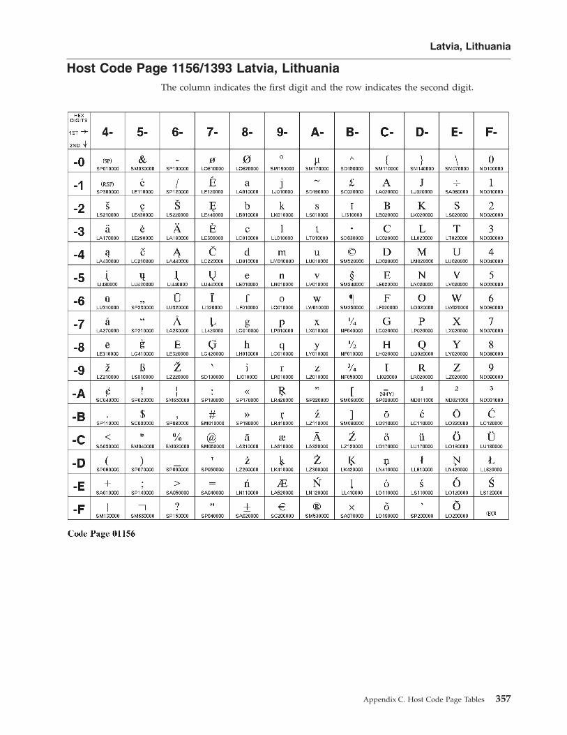
Host Code Page 1156/1393 Latvia, LithuaniaThe column indicates the first digit and the row indicates the second digit.
Latvia, Lithuania
Appendix C. Host Code Page Tables 357

Host Code Page 1157/1391 EstoniaThe column indicates the first digit and the row indicates the second digit.
Estonia
358 Personal Communications Administrator’s Guide and Reference

Host Code Page 1158/1388 UkraineThe column indicates the first digit and the row indicates the second digit.
Ukraine
Appendix C. Host Code Page Tables 359

Host Code Page 1160/1395 ThailandThe column indicates the first digit and the row indicates the second digit.
Thailand
360 Personal Communications Administrator’s Guide and Reference

Host Code Page 1164/1397 VietnamThe column indicates the first digit and the row indicates the second digit.
Vietnam
Appendix C. Host Code Page Tables 361

Vietnam
362 Personal Communications Administrator’s Guide and Reference

Appendix D. Alerts
Alerts are generated by components of Personal Communications; correspondingmessages are logged in the message log and can be viewed with the PersonalCommunications log viewer utility. Refer to the information about log viewerfunctions in the User’s Reference for the specific emulator type for moreinformation.
Note that some alerts can be caused by different situations. Each situation maygenerate a different message. Other alerts are informational and do not generatespecific messages in the log, although messages about problems relating to thesituation that generated the alert may be logged.
Alert ID number Messages logged
APPN
X’034A6F0B’ PCS4066EPCS4068EPCS4093E
X’0DF28A14’ PCS4065EPCS4066EPCS4068EPCS4069EPCS4070E
X’170F7710’ No specific messageX’21745F28’ No specific messageX’2313A399’ PCS4364A
PCS4365APCS4379A
X’32CDF4E2’ PCS4073EX’47302521’ No specific messageX’6D27D125’ PCS4066E
PCS4068EX’7599A7D8’ No specific messageX’769022F0’ PCS4504EX’9DCD7CCA’ PCS4275E
PCS4280EPCS4282EPCS4283APCS4284EPCS4304EPCS4305EPCS4310APCS4311EPCS4312E
X’9E452D9C’ PCS4593AX’A89646AA’ PCS4275E
PCS4280EPCS4282EPCS4283APCS4284EPCS4304EPCS4305EPCS4310APCS4311EPCS4312E
X’B558D310’ PCS4324EPCS4342EPCS4347E
X’C781E91E’ No specific message
© Copyright IBM Corp. 1989, 2002 363

X’EBAA3C4F’ PCS4593AX’EBEE390E’ PCS4063E
PCS4064EPCS4066EPCS4067EPCS4068EPCS4071APCS4091EPCS4092EPCS4094EPCS4123EPCS4124EPCS4125E
X’F52A0C01’ PCS4061EPCS4062E
X’FE1C42EB’ No specific messageLLC2 SAP
X’016E5F4E’ PCS1066APCS1054A
X’3BA03B6D’ PCS1066APCS1005E
X’55BF3E1C’ PCS1066APCS1054A
X’A676B230’ PCS1066APCS1005E
X’CAF3C58A’ PCS1066APCS1054A
X’D2E24978’ PCS1066APCS1005E
X’D615A61E’ PCS1066APCS1054A
X’EB1D6ABB’ PCS1066APCS1005E
X’EB61E14F’ PCS1066APCS1005E
LLC2 Link Station
X’216D1033’ PCS1065APCS1003E
X’25AC0D84’ PCS1065APCS1004E
X’28EF2B5D’ PCS1065APCS1001EPCS1004EPCS1006E
X’5B8F5BA7’ PCS1065APCS1050A
X’83D91642’ PCS1065APCS1000E
X’87180BF5’ PCS1065APCS1000E
X’8A5B2D2C’ PCS1065APCS1000E
X’8E9A309B’ PCS1065APCS1000E
X’E65B0B7F’ PCS1065A
pDLC
Alert ID number Messages logged Alert type Alert description
X’0E499026’ PCS8607 01 3300X’0F935B3E’ PCS8603 01 3300X’21C346F0’ PCS8619 01 3300X’25025B47’ PCS8620 01 3300
364 Personal Communications Administrator’s Guide and Reference

X’28417D9E’ PCS8617 01 3300X’2C806029’ PCS8618 01 3300X’4227687B’ PCS8610 01 3300X’6C6E2505’ PCS8604 01 8000
PCS8612X’7EA9C871’ PCS8608 01 3300X’8CEC6B74’ PCS8609 01 3300X’AB218ADF’ PCS8700 01 3300X’BB5C288E’ PCS8600 01 3300X’C16E9922’ PCS8615 01 3300X’C5AF8495’ PCS8616 01 3300X’C8ECA24C’ PCS8613 01 3300X’CC2DBFFB’ PCS8614 01 3300X’D3F9C6D8’ PCS8611 01 3300X’EBB67B65’ PCS8606 01 3300
Twinax DLC
Alert ID number Messages logged Alert type Alert description
X’24077791’ PCS8700 01 3300X’C91C002A’ PCS8107 01 3300X’D7D5F953’ PCS8101 01 3300
Appendix D. Alerts 365

366 Personal Communications Administrator’s Guide and Reference

Appendix E. Notices
This information was developed for products and services offered in the U.S.A.IBM may not offer the products, services, or features discussed in this document inother countries. Consult your local IBM representative for information on theproducts and services currently available in your area. Any reference to an IBMproduct, program, or service is not intended to state or imply that only that IBMproduct, program, or service may be used. Any functionally equivalent product,program, or service that does not infringe any IBM intellectual property right maybe used instead. However, it is the user’s responsibility to evaluate and verify theoperation of any non-IBM product, program, or service.
IBM may have patents or pending patent applications covering subject matterdescribed in this document. The furnishing of this document does not give youany license to these patents. You can send license inquiries, in writing, to:
IBM Director of LicensingIBM Corporation500 Columbus AvenueThornwood, NY 10594U.S.A.
For license inquiries regarding double-byte (DBCS) information, contact the IBMIntellectual Property Department in your country or send inquiries, in writing, to:
IBM World Trade Asia CorporationLicensing2-31 Roppongi 3-chome, Minato-kuTokyo 106, Japan
The following paragraph does not apply to the United Kingdom or any othercountry where such provisions are inconsistent with local law:INTERNATIONAL BUSINESS MACHINES CORPORATION PROVIDES THISPUBLICATION “AS IS” WITHOUT WARRANTY OF ANY KIND, EITHEREXPRESS OR IMPLIED, INCLUDING, BUT NOT LIMITED TO, THE IMPLIEDWARRANTIES OF NON-INFRINGEMENT, MERCHANTABILITY OR FITNESSFOR A PARTICULAR PURPOSE. Some states do not allow disclaimer of express orimplied warranties in certain transactions, therefore, this statement may not applyto you.
This information could include technical inaccuracies or typographical errors.Changes are periodically made to the information herein; these changes will beincorporated in new editions of the publication. IBM may make improvementsand/or changes in the product(s) and/or the program(s) described in thispublication at any time without notice.
Any references in this information to non-IBM documentation or non-IBM Websites are provided for convenience only and do not in any manner serve as anendorsement of those documents or Web sites. The materials for those documentsor Web sites are not part of the materials for this IBM product and use of thosedocuments or Web sites is at your own risk.
Licensees of this program who wish to have information about it for the purposeof enabling: (i) the exchange of information between independently created
© Copyright IBM Corp. 1989, 2002 367

programs and other programs (including this one) and (ii) the mutual use of theinformation which has been exchanged, should contact:
IBM CorporationDepartment T01Building 062P.O. Box 12195RTP, NC 27709-2195U.S.A.
Such information may be available, subject to appropriate terms and conditions,including in some cases, payment of a fee.
The licensed program described in this information and all licensed materialavailable for it are provided by IBM under terms of the IBM Customer Agreementor any equivalent agreement between us.
Information concerning non-IBM products was obtained from the suppliers ofthose products, their published announcements or other publicly available sources.IBM has not tested those products and cannot confirm the accuracy ofperformance, compatibility or any other claims related to non-IBM products.Questions on the capabilities of non-IBM products should be addressed to thesuppliers of those products.
All statements regarding IBM’s future direction or intent are subject to change orwithdrawal without notice, and represent goals and objectives only.
TrademarksThe following terms are trademarks of the IBM Corporation in the United States orother countries, or both:
AIXAdvanced Peer-to-Peer NetworkingAnyNetAPPNAS/400Client AccessCUADB2DB2 ConnectGDDMIBMIBM Global NetworkIBMLinkInfoWindowMicro ChannelNetfinity
OS/2OS/390OS/400OfficeVision/400OfficeVision/MVSOpen BlueprintRACFS/390SAASecureWaySystem/390TivoliTivoli/CourierTivoli EnterpriseTivoli/SentryVTAM
Lotus and 1–2–3 are trademarks of Lotus Development Corporation in the UnitedStates, other countries, or both.
Microsoft, Windows, Windows NT, and the Windows logo are registeredtrademarks of Microsoft Corporation in the United States, other countries, or both.
Java and all Java-based trademarks and logos are trademarks or registeredtrademarks of Sun Microsystems, Inc. in the United States, other countries, or both.
368 Personal Communications Administrator’s Guide and Reference

Other company, product, and service names may be trademarks or service marksof others.
Appendix E. Notices 369

370 Personal Communications Administrator’s Guide and Reference

Index
Numerics3270
configuring a second link 29configuring emulation to multiple hosts 30
3270 data stream (printing) 1773270 passthru 415250
automatic device name generation 23configuring a second link 29configuring emulation to multiple hosts 30
Aadapters
3270 via AS/400 41coax 35Ethernet 36Home3270 40IBM Global Network Connection 39IBM PCI Multiprotocol 49IBM SDLC PCMCIA 48LAN via IEEE 802.2 36OEM 51SDLC MPA 38Token-Ring 36twinax 46twinax, ISA-bus 46WAC 50
alerts xv, 363AnyNet
AnyNet examples 132AnyNet SNA over TCP/IP
configuration examples 132defining names 128, 129hints 131mapping 127overview 121routing preference protocol 130
APARs 11committing 12testing 12
Arabic support 158AS/400
3270 passthru 415250 sessions through one link 294configuration examples 293device description
for asynchronous attachments 297for twinaxial attachment 296
error messages 41system mode description 295system setup 41
asynchronous attachment, AS/400 device description 297asynchronous console 43
Bbidirectional language support
Arabiccharacter shape selection functions 160
bidirectional language support (continued)Arabic (continued)
installation 158keyboard functions for 3270 158limitations 158
Hebrewconfiguration 164functions for 5250 165general 162
printing considerations, Arabic and Hebrew 157VT, Arabic and Hebrew 166
CCertificate Management 83, 85Certificate Wizard 83, 84character sequences, unsupported 40character sets 149Chinese character set 153coax adapters 35code pages 313communication check 50x 40compiler, printer table
description of 175explanation 185printer color mixing 177printer definition file format 201
configuration3270 295250 29advanced configuration 19AS/400 examples 293multiple links 29
conflicts, preventing 48country codes 149CSDs 11, 15
Ddata stream support, printer
3270 178SCS 179
Database Access Utilitydata source, accessing 103general 103overview 101
delimiting print jobs 180
Eerror messages from the AS/400 system 41Express Logon
configuring 108preparing to configure 107problem determination 109using 107
© Copyright IBM Corp. 1989, 2002 371

Ffiles
configuration 19template 20update 20
HHebrew support 162Home3270 40host code page tables 313host-directed print 178
IIBM Global Network - SNA over Async 39IBM PC720 modem initialization 41IBMPCOMM Plus Module 54Information Bundler 10Information, Where to Find More
Alerts, Messages and xivMessages and Alerts xiv
Internet Service utility 11
JJapanese character set 152
Kkeyboard layouts 249
LLAN over COAX
configuring 42installing 41
LAN via IEEE 802.2 attachment 36language support
bidirectional 157multiple sessions 147overview 145Thai 155user interface languages 146
line speedHome3270 attachment 40IBM Global Network - SNA over Async attachment 39SDLC attachment 38
log viewer 9
Mmachine check 207 35messages
alerts xvOIA xvsystem fault xiv
messages generated by alerts 363
Nnode operations 120notices 367
OODBC driver
components 102overview 101
OEM adapter 51online help xiv
Ppassthru 41PCSPTC program 175, 185Personal Communications
functions 3library xvproblem analysis
APARs 12Information Bundler 10Internet Service 11log viewer 9overview 9trace facility 9
printer color mixing 177printer control codes 213printer data stream support
3270 178SCS 179
printer definition filesexamples 191field names 201symbols 208
printer definition table3270
data stream support 177delimiting print jobs 180overview 175PDF statements 175printer color mixing 177SCS TAB setting 177structured fields 181
PC400example files 191overview 185PDF file format 185transparent print capability 189using PDF file 185
printer function table migration utility 222problem analysis
CSDs 15Information Bundler 10Internet Service 11log viewer 9overview 9trace facility 9
Problem analysisAPARs 12
SSCS data stream (printing) 177SDLC MPA adapter 38security
configuring SSL 77using SSL 77
sessionsquerying 27
372 Personal Communications Administrator’s Guide and Reference

sessions (continued)starting 26stopping 26
shift support 150SNA Client/Server concepts
APPC concepts 113general 113SNA communications 119SNA node operations 120terminology 113
SNA node operations 120SSL security
Certificate Management 83, 85Certificate Wizard 83, 84configuring
client 78server and related client 77
general 77password, changing 82problem determination 87references 87secure session icon 79smart card support 88smart card support, enabling 88SSL-Based session 79
SSL supportadvanced security setup 81automatic host location 80configuring 80host definition 80pop-up messages 82
SSL, configuringadding root certificate 84using unknown CA 84using well-known CA 83
system policy supportconfiguration policy 68execution policy 72file transfer 74installation policy 74overview 67
TTCP/IP
connection considerations 36protocol driver 36
Tivoli 53event management 58inventory database 65remote installation of Personal Communications 53software distribution 63task administration 54
trace facility 9trademarks 368twinax
adapters, using 46attachment, AS/400 device description 296
twinax connections 43twinaxial console 42
UUnicode support
1390/1399 code pages 169Hindi 170
Unicode support (continued)overview 169
unsupported character sequences 40
WWebUpdate
APARs 11CSDs 11
Index 373

374 Personal Communications Administrator’s Guide and Reference
Readers’ Comments — We’d Like to Hear from You
Personal Communications for Windows, Version 5.6Administrator’s Guide and Reference
Publication No. SC31-8840-01
Overall, how satisfied are you with the information in this book?
Very Satisfied Satisfied Neutral Dissatisfied VeryDissatisfied
Overall satisfaction h h h h h
How satisfied are you that the information in this book is:
Very Satisfied Satisfied Neutral Dissatisfied VeryDissatisfied
Accurate h h h h h
Complete h h h h h
Easy to find h h h h h
Easy to understand h h h h h
Well organized h h h h h
Applicable to your tasks h h h h h
Please tell us how we can improve this book:
Thank you for your responses. May we contact you? h Yes h No
When you send comments to IBM, you grant IBM a nonexclusive right to use or distribute your comments in anyway it believes appropriate without incurring any obligation to you.
Name Address
Company or Organization
Phone No.

Readers’ Comments — We’d Like to Hear from YouSC31-8840-01
SC31-8840-01
����Cut or FoldAlong Line
Cut or FoldAlong Line
Fold and Tape Please do not staple Fold and Tape
Fold and Tape Please do not staple Fold and Tape
NO POSTAGENECESSARYIF MAILED IN THEUNITED STATES
BUSINESS REPLY MAILFIRST-CLASS MAIL PERMIT NO. 40 ARMONK, NEW YORK
POSTAGE WILL BE PAID BY ADDRESSEE
IBM CorporationInformation DevelopmentDepartment CGMD / Bldg 500P.O. Box 12195Research Triangle Park, NC27709-9990
_ _ _ _ _ _ _ _ _ _ _ _ _ _ _ _ _ _ _ _ _ _ _ _ _ _ _ _ _ _ _ _ _ _ _ _ _ _ _ _ _ _ _ _ _ _ _ _ _ _ _ _ _ _ _ _ _ _ _ _ _ _ _ _ _ _ _ _ _ _ _ _ _ _ _ _ _ _ _ _ _ _ _ _ _ _ _ _ _
_ _ _ _ _ _ _ _ _ _ _ _ _ _ _ _ _ _ _ _ _ _ _ _ _ _ _ _ _ _ _ _ _ _ _ _ _ _ _ _ _ _ _ _ _ _ _ _ _ _ _ _ _ _ _ _ _ _ _ _ _ _ _ _ _ _ _ _ _ _ _ _ _ _ _ _ _ _ _ _ _ _ _ _ _ _ _ _ _
__
__
__
__
__
__
__
__
__
__
__
__
__
__
__
__
__
__
__
__
__
__
__
__
__
__
__
__
__
__
__
__
__
__
__
__
__
__
__
__
__
__
__
__
__
__
__
__
__
_


����
Program Number: 5639–I70
Printed in U.S.A.
SC31-8840-01