personal flotation devices — materials and components ...pontofocal... · iso (the international...
TRANSCRIPT

Reference numberISO 12402-7:2006/Amd.1:2011(E)
© ISO 2011
INTERNATIONAL STANDARD
ISO12402-7
First edition2006-11-15
AMENDMENT 12011-04-01
Personal flotation devices — Part 7: Materials and components — Safety requirements and test methods
AMENDMENT 1
Équipements individuels de flottabilité —
Partie 7: Matériaux et composants — Exigences de sécurité et méthodes d'essai
AMENDEMENT 1

ISO 12402-7:2006/Amd.1:2011(E)
PDF disclaimer This PDF file may contain embedded typefaces. In accordance with Adobe's licensing policy, this file may be printed or viewed but shall not be edited unless the typefaces which are embedded are licensed to and installed on the computer performing the editing. In downloading this file, parties accept therein the responsibility of not infringing Adobe's licensing policy. The ISO Central Secretariat accepts no liability in this area.
Adobe is a trademark of Adobe Systems Incorporated.
Details of the software products used to create this PDF file can be found in the General Info relative to the file; the PDF-creation parameters were optimized for printing. Every care has been taken to ensure that the file is suitable for use by ISO member bodies. In the unlikely event that a problem relating to it is found, please inform the Central Secretariat at the address given below.
COPYRIGHT PROTECTED DOCUMENT © ISO 2011 All rights reserved. Unless otherwise specified, no part of this publication may be reproduced or utilized in any form or by any means, electronic or mechanical, including photocopying and microfilm, without permission in writing from either ISO at the address below or ISO's member body in the country of the requester.
ISO copyright office Case postale 56 • CH-1211 Geneva 20 Tel. + 41 22 749 01 11 Fax + 41 22 749 09 47 E-mail [email protected] Web www.iso.org
Published in Switzerland
ii © ISO 2011 – All rights reserved
ISO 12402-7:2006/Amd.1:2011(E)
© ISO 2011 – All rights reserved iii
Foreword
ISO (the International Organization for Standardization) is a worldwide federation of national standards bodies (ISO member bodies). The work of preparing International Standards is normally carried out through ISO technical committees. Each member body interested in a subject for which a technical committee has been established has the right to be represented on that committee. International organizations, governmental and non-governmental, in liaison with ISO, also take part in the work. ISO collaborates closely with the International Electrotechnical Commission (IEC) on all matters of electrotechnical standardization.
International Standards are drafted in accordance with the rules given in the ISO/IEC Directives, Part 2.
The main task of technical committees is to prepare International Standards. Draft International Standards adopted by the technical committees are circulated to the member bodies for voting. Publication as an International Standard requires approval by at least 75 % of the member bodies casting a vote.
Attention is drawn to the possibility that some of the elements of this document may be the subject of patent rights. ISO shall not be held responsible for identifying any or all such patent rights.
Amendment 1 to ISO 12402-7:2006 was prepared by Technical Committee ISO/TC 188, Small craft, Subcommittee SC 1, Personal safety equipment, in collaboration with Technical Committee CEN/TC 162, Protective clothing including hand and arm protection and lifejackets.

ISO 12402-7:2006/Amd.1:2011(E)
© ISO 2011 – All rights reserved 1
Personal flotation devices —
Part 7: Materials and components — Safety requirements and test methods
AMENDMENT 1
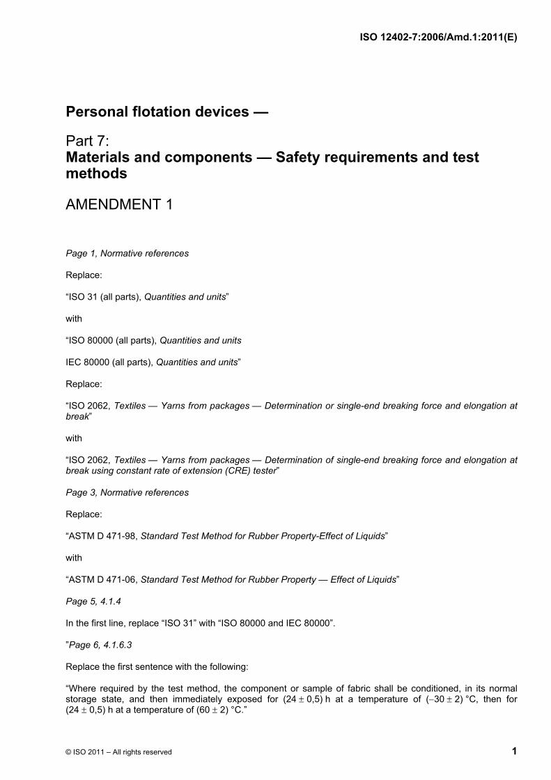
Page 1, Normative references
Replace:
“ISO 31 (all parts), Quantities and units”
with
“ISO 80000 (all parts), Quantities and units
IEC 80000 (all parts), Quantities and units”
Replace:
“ISO 2062, Textiles — Yarns from packages — Determination or single-end breaking force and elongation at break”
with
“ISO 2062, Textiles — Yarns from packages — Determination of single-end breaking force and elongation at break using constant rate of extension (CRE) tester”
Page 3, Normative references
Replace:
“ASTM D 471-98, Standard Test Method for Rubber Property-Effect of Liquids”
with
“ASTM D 471-06, Standard Test Method for Rubber Property — Effect of Liquids”
Page 5, 4.1.4
In the first line, replace “ISO 31” with “ISO 80000 and IEC 80000”.
”Page 6, 4.1.6.3
Replace the first sentence with the following:
“Where required by the test method, the component or sample of fabric shall be conditioned, in its normal storage state, and then immediately exposed for (24 ± 0,5) h at a temperature of (−30 ± 2) °C, then for (24 ± 0,5) h at a temperature of (60 ± 2) °C.”

ISO 12402-7:2006/Amd.1:2011(E)
2 © ISO 2011 – All rights reserved
Page 7, 4.1.6.4
Add the following after the last list item:
“NOTE This test is not applicable to fabrics related to PFDs complying with ISO 12402-5.”
Page 8, 4.3.2.2
Replace the complete subclause with the following:
“4.3.2.2 Textile woven fabrics shall have an as-received tensile strength as specified in Table 2, measured using the grab method given in ISO 13934-2.”
Page 8, 4.3.2.3
Replace the complete subclause with the following:
“4.3.2.3 Textile knitted fabrics shall have an as-received burst strength as specified in Table 2, measured using the method given in ISO 13938-1 or ISO 13938-2.”
Page 9, Table 2
Replace Table 2 with the following:
Table 2 — Fabric
Property Exposure Test method Number of samples
Sample sizea
(mm × mm) Compliance criteria
Tensile strength (woven fabrics only)
1 Standard conditioning
2 Accelerated weathering according to 4.1.6.4
3 70 h immersion in:
3.1 fuel B according to ASTM D 471-06 or diesel fuel according to EN 590b
3.2 0,5 % detergent according to ISO 6330
ISO 13934-2, except that jaw breaks may be included in the average results.
5 warp and 5 weft for each separate exposure
As specified by test method
Following exposure 1, the average of 5 samples shall be at least 400 N for each direction.
Following each separate exposure 2 and 3, the average of 5 samples shall be at least 260 N.

ISO 12402-7:2006/Amd.1:2011(E)
© ISO 2011 – All rights reserved 3
Table 2 (continued)
Property Exposure Test method Number of samples
Sample sizea
(mm × mm) Compliance criteria
Bursting strength (knitted fabrics only)
1 Standard conditioning
2 Accelerated weathering according to 4.1.6.4
3 70 h immersion in:
3.1 fuel B according to ASTM D 471-06 or diesel fuel according to EN 590b
3.2 0,5 % detergent according to ISO 6330
ISO 13938-1 or ISO 13938-2
10 for each separate exposure
130 × 130 Following exposure 1, the average of 10 samples shall be at least 800 kPa.
Following each separate exposure in 2 and 3, the average of 10 samples shall retain at least 60 % of the strength determined following standard conditioning.
Elongation at break (woven fabrics only)
Standard conditioning
ISO 13934-1 5 warp and 5 weft
As specified by test method
Following standard conditioning, the average of 5 samples shall not exceed a 60 % increase of elongation at break.
Tearing strength (woven fabrics only)
Standard conditioning
ISO 13937-2 5 warp 5 weft
50 × 200 The average of 5 samples shall be at least 25 N for each direction.
Yarn slippage (woven fabrics only)
Standard conditioning
See 4.3.2.6 5 warp 5 weft
100 × 150 The average of 5 samples shall be at least 220 N.
Openness of weavec
Standard conditioning
See 4.3.2.7 The openness of weave shall not exceed 20 %.
Adhesion strengthd
Standard conditioning
ISO 2411 2 warp and2 weft or 5 warp and5 weft
50 × 200 or 75 × 200
The coating adhesion shall be at least 7 N/cm.
a Applies to each colour except for fabrics related to PFDs complying with ISO 12402-5, where a minimum of one colour shall be tested.
b Exposure tests shall be based on typical fuels used in the intended area of application.
c Applies to external cover fabrics only, not to gusset, lining, or drainage fabric.
d Applies only to coated fabric with a coating of 185 g/m2 or more and where the base fabric or scrim does not comply with the applicable strength requirements when fabric is uncoated.

ISO 12402-7:2006/Amd.1:2011(E)
4 © ISO 2011 – All rights reserved
Page 12, 4.3.3.2
Replace the complete subclause with the following:
“4.3.3.2 The colour of the material samples shall be measured using the procedures defined in CIE publication No. 15.2 with polychromatic illumination D65, 45/0 geometry and 2° standard observer. The specimen shall have a black underlay with a reflectance of less than 0,04. The specimens shall be conditioned for at least 24 h at (20 ± 2) °C and (65 ± 5) % relative humidity. If the test is carried out in other conditions, the test shall be conducted within 5 min after withdrawal from the conditioning atmosphere.”
Page 12, 4.3.3.3
Delete the complete subclause 4.3.3.3 and renumber current subclause 4.3.3.4 as 4.3.3.3.
Page 12, Table 3
Replace Table 3 with the following:
Table 3 — Chromaticity coordinates x and y and luminance factor β for yellow, orange and red non-fluorescent colours of lifejacket material
Chromaticity coordinates Luminance factor Colour
x y β
Yellow 0,389 0,320 0,405 0,500
0,610 0,490 0,400 0,500
> 0,35
Orange 0,500 0,405 0,470 0,600
0,500 0,400 0,330 0,400
> 0,25
Red 0,600 0,470 0,525 0,700
0,400 0,330 0,270 0,300
> 0,15

ISO 12402-7:2006/Amd.1:2011(E)
© ISO 2011 – All rights reserved 5
Page 13, Table 4
Replace Table 4 with the following:
Table 4 — Chromaticity coordinates x and y and luminance factor β for yellow, yellow-orange, orange, orange-red and red fluorescent colours of lifejacket material
Chromaticity coordinates Luminance factor Colour
x y β
Fluorescent yellow 0,380 0,320 0,370 0,440
0,610 0,490 0,440 0,550
> 0,60
Fluorescent yellow–orange 0,440 0,370 0,420 0,505
0,550 0,440 0,390 0,490
> 0,50
Fluorescent orange 0,505 0,420 0,460 0,575
0,490 0,390 0,350 0,425
> 0,40
Fluorescent orange–red 0,575 0,460 0,488 0,630
0,425 0,350 0,320 0,360
> 0,30
Fluorescent red 0,630 0,488 0,525 0,695
0,360 0,320 0,280 0,300
> 0,20
ISO 12402-7:2006/Amd.1:2011(E)
6 © ISO 2011 – All rights reserved
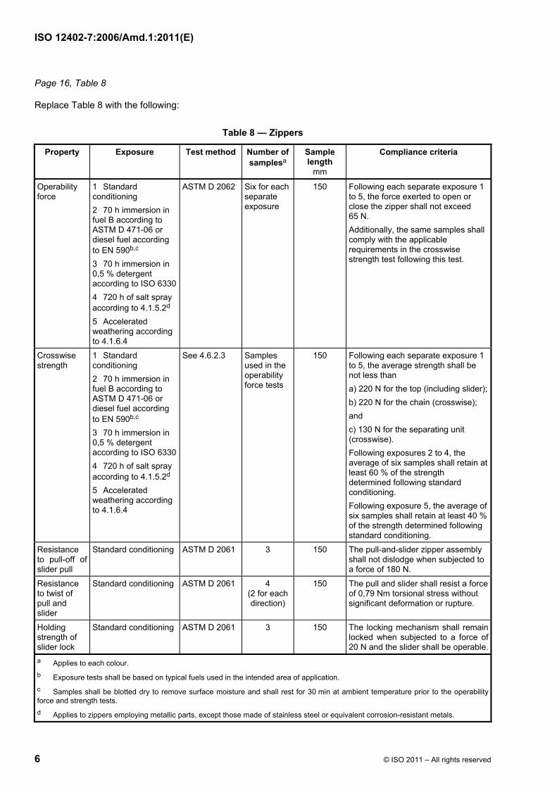
Page 16, Table 8
Replace Table 8 with the following:
Table 8 — Zippers
Property Exposure Test method Number of samplesa
Sample length
mm
Compliance criteria
Operability force
1 Standard conditioning 2 70 h immersion in fuel B according to ASTM D 471-06 or diesel fuel according to EN 590b,c 3 70 h immersion in 0,5 % detergent according to ISO 6330 4 720 h of salt spray according to 4.1.5.2d 5 Accelerated weathering according to 4.1.6.4
ASTM D 2062 Six for each separate exposure
150 Following each separate exposure 1 to 5, the force exerted to open or close the zipper shall not exceed 65 N. Additionally, the same samples shall comply with the applicable requirements in the crosswise strength test following this test.
Crosswise strength
1 Standard conditioning 2 70 h immersion in fuel B according to ASTM D 471-06 or diesel fuel according to EN 590b,c 3 70 h immersion in 0,5 % detergent according to ISO 6330 4 720 h of salt spray according to 4.1.5.2d 5 Accelerated weathering according to 4.1.6.4
See 4.6.2.3 Samples used in the operability force tests
150 Following each separate exposure 1 to 5, the average strength shall be not less than a) 220 N for the top (including slider);b) 220 N for the chain (crosswise); and c) 130 N for the separating unit (crosswise). Following exposures 2 to 4, the average of six samples shall retain at least 60 % of the strength determined following standard conditioning. Following exposure 5, the average of six samples shall retain at least 40 % of the strength determined following standard conditioning.
Resistance to pull-off of slider pull
Standard conditioning ASTM D 2061 3 150 The pull-and-slider zipper assembly shall not dislodge when subjected to a force of 180 N.
Resistance to twist of pull and slider
Standard conditioning ASTM D 2061 4 (2 for each direction)
150 The pull and slider shall resist a force of 0,79 Nm torsional stress without significant deformation or rupture.
Holding strength of slider lock
Standard conditioning ASTM D 2061 3 150 The locking mechanism shall remain locked when subjected to a force of 20 N and the slider shall be operable.
a Applies to each colour. b Exposure tests shall be based on typical fuels used in the intended area of application. c Samples shall be blotted dry to remove surface moisture and shall rest for 30 min at ambient temperature prior to the operability force and strength tests. d Applies to zippers employing metallic parts, except those made of stainless steel or equivalent corrosion-resistant metals.

ISO 12402-7:2006/Amd.1:2011(E)
© ISO 2011 – All rights reserved 7
Page 19, Table 9
Replace Table 9 with the following:
Table 9 — Webbing closures and adjusters
Property Exposure Test method Number of samplesa,b
Compliance criteria
Tensile strength
1 Standard conditioning
2 70 h immersion in fuel B according to ASTM D 471-06 or diesel fuel according to EN 590c,d
3 70 h immersion in 0,5 % detergent according to ISO 6330
4 (70 ± 2) °C for 7 daysc
5 (−30 ± 2) °C for 24 he
6 720 h of salt spray according to 4.1.5.2
7 Fatiguef
8 Accelerated weathering according to 4.1.6.4
See 4.7.1.2.1 5 for each separate conditioning
Following each separate exposure 1 to 8
a) hardware shall have a minimum strength of 890 N; or
b) where hardware is intended for use in meeting the PFD horizontal load test requirement for lifejackets, or is a single load-bearing member intended for use in meeting the PFD horizontal load test requirement for buoyancy aids, hardware shall have a minimum tensile strength of 1 600 N.
For exposures 2 to 8, the average of 5 samples shall retain at least 60 % of the strength that determined from standard conditioning.

ISO 12402-7:2006/Amd.1:2011(E)
8 © ISO 2011 – All rights reserved
Table 9 (continued)
Property Exposure Test method Number of samplesa, b
Compliance criteria
Strength/ slippage
1 Standard conditioning
2 2 min water soakf
3 The same exposure as tensile strength exposure that resulted in greatest percentage strength lossg
See 4.7.1.2.2 5 for each separate exposure
For exposures 1 to 3, each sample shall support, without breaking, distorting, or slipping more than 25 mm, a load of:
a) 890 Nh;
b) 1 600 N for 30 min where hardware is intended for use in meeting the PFD horizontal load test requirement for lifejackets, or is a single load-bearing member intended for use in meeting the PFD horizontal load test requirement for buoyancy aids.
Inadvertent release test (dual-tab closures only)
Standard conditioning See 4.7.1.2.3 5 Each sample shall support for 5 min,without breaking, disengagement, or similar condition, a load of at least 50 % of the minimum tensile strength specified for exposure 1 in the tensile strength test for the standard conditioning using webbing for PFDs.
a Applies to each colour.
b A minimum of 75 hardware/webbing samples.
c Samples shall be blotted dry to remove surface moisture and shall rest for 30 min at ambient temperature prior to the strength test.
d Exposure tests shall be based on typical fuels used in the intended area of application.
e Immediately following removal from the cold chamber, the samples shall be dropped using different orientations onto a concrete floor five times from a height of 1 800 mm. Each sample shall then be manually operated five times and examined for signs of cracking. The samples shall then be returned to the cold chamber for 15 min. Finally, the samples shall be individually removed and subjected to the tensile strength test and strength/slippage test.
f The webbing which is used for the applicable tests in 4.7.1.2.1 shall be soaked in fresh water for 2 min prior to the strength/slippage test.
g Each flexible or moveable tab of a polymeric part shall be mechanically operated for 5 000 cycles at a rate of 1 cycle/s. The tab shall be completely engaged/disengaged. Also, for hardware which is designed to separate into two parts (i.e. buckles), the parts shall be completely engaged/disengaged. In addition, the samples shall be manually operated five times prior to the tensile strength test and strength/slippage test.
h Strength values are for the fixed-straight-length body strap method. The values shall be doubled for the closed-loop assembly method.

ISO 12402-7:2006/Amd.1:2011(E)
© ISO 2011 – All rights reserved 9
Page 23, Table 10
Replace Table 10 with the following:
Table 10 — Lacing closures and adjusters
Property Exposure Test method Number of samplesa, b
Compliance criteria
Tensile strength
1 Standard conditioning
2 70 h immersion in fuel B according to ASTM D 471-06 or diesel fuel according to EN 590c,d
3 70 h immersion in 0,5 % detergent according to ISO 6330
4 (70 ± 2) °C for 7 dc
5 (−30 ± 2) °C for 24 he
6 720 h of salt spray according to 4.1.5.2
7 Fatiguef
8 Accelerated weathering according to 4.1.6.4
See 4.7.2.2.1 5 for each separate exposure
Following each separate exposure 1 to 7, each sample shall have a minimum breaking strength of 1 000 N.
Also, for exposures 2 to 8, the average of 5 samples shall retain at least 60 % of the strength determined from standard conditioning.
Strength/ slippage
1 Standard conditioning
2 2 min water soakg
See 4.7.2.2.2 5 for each separate exposure
For exposures 1 and 2, each sample shall support, without breaking, distorting, or slipping more than 25 mm, a weight of 1 000 N for 10 min using the fixed-straight-length body strap method. The load is to be doubled for the closed-loop assembly method.
Tab disen-gagement test
Standard conditioning See 4.7.2.2.3 5 A moveable tab shall remain engaged and operable when subjected to a shock load of (6,8 ± 0,2) J.
a Applies to each colour.
b For polymeric hardware, a minimum of 80 samples. For metal hardware, 35 hardware samples.
c Samples shall be blotted dry to remove surface moisture and shall rest for 30 min at ambient temperature prior to the strength test.
d Exposure tests shall be based on typical fuels used in the intended area of application.
e Immediately following removal from the cold chamber, the samples shall be dropped using different orientations onto a concrete floor five times from a height of 1 800 mm. Each sample shall then be manually operated five times and examined for signs of cracking.The samples shall then be returned to the cold chamber for 15 min. Finally, the samples shall be individually removed and subjected to the tensile strength test and strength/slippage test.
f Each flexible or moveable tab of a polymeric part shall be mechanically operated for 5 000 cycles at a rate of 1 cycle/s. The tab shall be completely engaged/disengaged. Also, for hardware which is designed to separate into two parts (i.e. buckles), the parts shall be completely engaged/disengaged. In addition, the samples shall be manually operated five times prior to the tensile strength test and strength/slippage test.
g The lacing which is used for the applicable tests in 4.7.2.2.2 shall be soaked in fresh water for 2 min prior to the strength/slippage test.

ISO 12402-7:2006/Amd.1:2011(E)
10 © ISO 2011 – All rights reserved
Page 25, Table 12
Replace Table 12 with the following:
Table 12 — Foam flotation material
Property Test method Number of samples Compliance criteriaa
Density See 4.8.2.1 18b Baseline test.
Specific buoyancy See 4.8.2.2 18 Baseline test.
Compressionc See 4.8.2.4 or 4.8.2.5d 3e The maximum loss of buoyancy for the average of all samples shall not exceed 10 %.
Thermal stabilityc See 4.8.2.3 or 4.8.2.5d 3c The maximum loss of volume in any sample shall not exceed 5 % and there shall be no sign of damage such as shrinking, cracking, swelling, dissolution or change of mechanical qualities, when compared with unconditioned specimens.d
Buoyancy retention factors, alternative to compression and thermal stability:c,d V-factor (for wearable devices)
4.8.2.5 9e,f 94 V for material used to make up at least 85 % of the required buoyancy in a PFD meeting the requirements of ISO 12402-1 to ISO 12402-3.
85 V for material used to make up at least 85 % of the required buoyancy in a PFD meeting the requirements of ISO 12402-4 to ISO 12402-6.
80 V for material making up no more than 15 % of the required buoyancy in any PFD.
Tensile strength See 4.8.2.6 5g The average tensile strength shall be not less than 140 kPa for foam that is a structural part of the device, i.e. not retained by a cover fabric.
Oil resistance See 4.8.2.7 3f There shall be no visible volume change, softening, or deterioration of a material when compared with unconditioned specimens, and the average tensile strength of the material shall be not less than 75 % of the value determined for the unconditioned specimens.
Cold flexibility See 4.8.2.8 3f There shall be no cracking when examined under a magnification of 5 ×.
Compression deflection
See 4.8.2.9 3g The force required to deflect the material to 75 % of its original thickness shall be at least 7 kPa.
Dimensional analysis See 4.8.2.10 1 Baseline test.
Thickness See 4.8.2.11 4h The average thickness shall be within ± 10 % of the design values.
a The use of foam buoyant material is dependent on (but not limited to) the thickness, the buoyancy retention factor, the type of the personal flotation device for which it is intended, and on how it is enclosed in the personal flotation device. b Six samples shall be taken from each of three lots of foam flotation material. c This property shall be investigated for each nominal thickness in which the foam flotation material is produced, except that for material produced in thicknesses greater than 25 mm, a plot of property values versus thickness based upon at least three thicknesses(thinnest, mid-range, and thickest) of 25 mm and greater shall be used to obtain values for intermediate thickness. d When the alternative tests in 4.8.2.5 are used, the resulting retention factors shall be used to compensate for the projected loss of buoyancy as specified in 5.3.4.2 of ISO 12402-1 to ISO 12402-6. e The samples shall be the same samples used in the specific buoyancy measurements. f Samples from one or more lots. g One sample from each lot. h Two samples from batch 1 and one sample each from batches 2 and 3.

ISO 12402-7:2006/Amd.1:2011(E)
© ISO 2011 – All rights reserved 11
Page 27, 4.8.2.3
Replace the complete subclause with the following:
“4.8.2.3 Thermal stability of buoyancy material
Three test specimens of dimensions (200 ± 2) mm × (200 ± 2) mm and of thickness (20 ± 2) mm shall be conditioned initially in air at (23 ± 2) °C and (50 ± 5) % relative humidity for at least 24 h before carrying out the test. If the buoyancy material is of a granular form or consists of sheets thinner than 20 mm, then either a number of layers shall be used to achieve a minimum total thickness of 20 mm, or a minimum volume of material of 0,1 l shall be tested, as appropriate.
Each specimen shall then be weighed in air, and undergo measurements to determine its volume. If the volume is measured by displacement of water, the specimens shall be conditioned in air at (23 ± 2) °C and a relative humidity of (50 ± 5) % for (24 ± 0,5) h.
They shall then be placed on a flat surface in an oven maintained at an even temperature of (60 ± 1) °C with air circulating at the rate of 3 to 10 changes per hour, for a period of (7 ± 0,1) h. Only test specimens from the same type of material shall be conditioned in one oven at a given time.
Following removal from the oven, specimens shall be laid on a flat surface for (17 ± 0,1) h at (23 ± 2) °C and (50 ± 5) % relative humidity.
They shall then be exposed in a similar container to an even temperature of (−30 ± 1) °C for a period of (7,0 ± 0,1) h, then removed and laid on the flat surface for (17,0 ± 0,1) h at room temperature as before.
This cycle of exposure to alternating high and low temperatures shall be repeated until the samples have been exposed to each temperature for ten periods. The measurements shall then be repeated, and the percentage volume change calculated.”
Page 28, 4.8.2.4
Replace the complete subclause with the following:
“4.8.2.4 Test method for the compressibility of inherently buoyant material
4.8.2.4.1 Examine three specimens of each sample of foam of dimensions (100 ± 2) mm × (100 ± 2) mm and of thickness (20 ± 2) mm. If the material consists of granules, then fill three cloth sacks with the granules to the same filling density as the lifejacket or buoyancy aid. Fit them into a metal frame of dimensions (100 × 100) mm and a height equivalent to the thickness of the buoyancy aid. Prior to the test, they shall have been stored at (23 ± 2) °C and a relative humidity of (50 ± 5) % for at least 24 h, and they shall be tested under these conditions.
4.8.2.4.2 Each specimen shall be placed in fresh water under a flat metal plate at least 20 % larger than the specimen size and then compressed at a speed of 200 mm/min until a load of 50 kPa has been reached. This lower position shall be set for further compressions. The specimen shall then be completely decompressed, and the cycle of compression repeated a further four times, using the lower set-point as the limit of compression.
4.8.2.4.3 The specimen shall then be kept under the metal plate such that it is only just weighted by the plate to remain under water. The load required to achieve this shall be recorded as the original buoyancy.
NOTE It will almost certainly be necessary to use a different load cell from that required in 4.8.2.4.2.
4.8.2.4.4 The specimen shall then be dried for 7 d in air at a temperature of (23 ± 2) °C and a relative humidity of (50 ± 5) %. The compression cycle in 4.8.2.4.2 shall then be repeated without water, and for a total of 500 times. If deformation occurs, then the upper set-point might need to be reset in order to keep the decompression time equal during the whole period.

ISO 12402-7:2006/Amd.1:2011(E)
12 © ISO 2011 – All rights reserved
4.8.2.4.5 The specimen shall then be returned to the atmosphere in 4.8.2.4.4 for at least 3 d, and the buoyancy measurement in 4.8.2.4.2 and 4.8.2.4.3 repeated, giving the value B. The loss of buoyancy (calculated as A − B) shall then be expressed as a percentage of the original buoyancy (A).”
Page 32, 4.9.1
Replace the third paragraph with the following:
“If the material is susceptible to fungal attack and is used as a water-resistant membrane, a test shall be carried out as specified in Annex A.”
Page 34, Table 13
Replace Table 13 with the following:
Table 13 — Inflation chamber materials
Property Exposure Test method
Number of samples
Sample size mm × mm
Compliance criteria
Tensile strength (woven fabrics only)
1 Standard conditioning
2 Accelerated ageing: 168 h at 70 °C
3 After soil burial and fungus resistance (12 weeks' exposure), see Annex A
4 Accelerated weathering according to 4.1.6.4a,b
ISO 13934-2 5 warp and 5 weft for each exposure
100 × 150 Following exposure 1, the five-sample average shall be at least 930 N in the direction of greater thread count and 800 N in the direction of lesser thread count.
Following exposures 2 and 3, the five-sample average for each direction shall retain at least 90 % of that value determined following standard conditioning.
Following exposure 4, the five-sample average for each direction shall retain at least 260 N determined following standard conditioning.
Trapezoid tear strength (woven fabrics only)
1 Standard conditioning
2 Accelerated ageing: 168 h at 70 °C
ISO 9073-4 5 warp and 5 weft for each condi-tioning
75 × 150 Following exposure 1, the five-sample average for each direction shall be at least 45 N in the warp direction and 36 N in the filling direction.
Following exposure 2, the five-sample average for each direction shall retain at least 90 % of the value determined following standard conditioning.
Perme-ability
1 Standard conditioning
2 Accelerated ageing: 168 h at 70 °C
3 After soil burial and fungus resistance (12 weeks' exposure), see Annex A
4 (65 ± 1) °C at 95 % relative humidity for 360 h
ISO 7229, using CO2 gas
3 for each exposure
125 × 125 Following exposure 1, identification test.
Following exposures 2 to 4, the three-sample average for each direction shall not exceed 110 % of the value determined following standard conditioning.

ISO 12402-7:2006/Amd.1:2011(E)
© ISO 2011 – All rights reserved 13
Table 13 (continued)
Property Exposure Test method
Number of samples
Sample size mm × mm
Compliance criteria
Abrasion resistance (woven fabrics)
1 Standard conditioning
2 After abrasion resistance, 9 N pressure, and 100 000 double rubs
ISO 12947-2 See also Annex B
8 warp and 8 weft for each exposure
250 × 50 Except for a material intended for use under a fabric envelope or otherwise protected, the eight-sample average for each direction shall retain at least 75 % of the value determined following standard conditioning.
Adhesion 1 Standard conditioning
2 After 42 d at 70 °C over water
ISO 2411 5 75 × 200 After conditioning 1: 180 N per 50 mm
After conditioning 2: 150 N per 50 mm
Flexibility 1 Standard conditioning
2 After 42 d at 70 °C over water
ISO 7854:1995, Method A
3 (37,5 ± 0,1)× 125
After conditioning 1: no cracking after 9 000 cycles
After conditioning 2: no cracking after 9 000 cycles
a For fully inflated and packed conditions, only exposure 4 weathering shall be conducted for a material not intended to be fully encased within a cover fabric.
b Every colour shall be weathered.
ISO 12402-7:2006/Amd.1:2011(E)
14 © ISO 2011 – All rights reserved
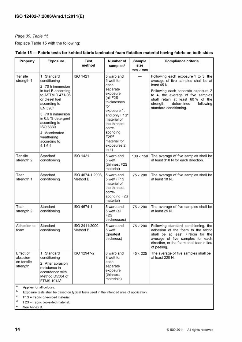
Page 39, Table 15
Replace Table 15 with the following:
Table 15 — Fabric tests for knitted fabric laminated foam flotation material having fabric on both sides
Property Exposure Test method
Number of samplesa
Sample size
mm × mm
Compliance criteria
Tensile strength 1
1 Standard conditioning 2 70 h immersion in fuel B according to ASTM D 471-06 or diesel fuel according to EN 590b 3 70 h immersion in 0,5 % detergent according to ISO 6330 4 Accelerated weathering according to 4.1.6.4
ISO 1421 5 warp and 5 weft for each separate exposure (all F2S thicknesses for exposure 1; and only F1Sc material of the thinnest corre-sponding F2Sd material for exposures 2 to 4)
— Following each exposure 1 to 3, the average of five samples shall be at least 45 N. Following each separate exposure 2 to 4, the average of five samples shall retain at least 60 % of the strength determined following standard conditioning.
Tensile strength 2
Standard conditioning
ISO 1421 5 warp and 5 weft (thinnest F2S material)
100 × 150 The average of five samples shall be at least 310 N for each direction.
Tear strength 1
Standard conditioning
ISO 4674-1:2003, Method B
5 warp and 5 weft (F1S material of the thinnest corre-sponding F2S material)
75 × 200 The average of five samples shall be at least 18 N.
Tear strength 2
Standard conditioning
ISO 4674-1 5 warp and 5 weft (all F2S thicknesses)
75 × 200 The average of five samples shall be at least 25 N.
Adhesion to foam
Standard conditioning
ISO 2411:2000, Method B
5 warp and 5 weft (greatest thickness)
75 × 200 Following standard conditioning, the adhesion of the foam to the fabric shall be at least 7 N/cm for the average of five samples for each direction, or the foam shall tear in lieu of peeling.
Effect of abrasion on tensile strength
1 Standard conditioning 2 After abrasion resistance in accordance with Method D5304 of FTMS 191Ae
ISO 12947-2 8 warp and 8 weft for each separate exposure (thinnest materials)
45 × 225 The average of five samples shall be at least 220 N.
a Applies for all colours. b Exposure tests shall be based on typical fuels used in the intended area of application. c F1S = Fabric one-sided material. d F2S = Fabric two-sided material. e See Annex B.

ISO 12402-7:2006/Amd.1:2011(E)
© ISO 2011 – All rights reserved 15
Page 40, Table 16
Replace Table 16 with the following:
Table 16 — Fabric tests for knitted fabric laminated foam flotation material having fabric on one side
Property Exposure Test method
Number of samplesa
Sample size
mm × mm
Compliance criteria
Tensile strength 1
1 Standard conditioning
2 70 h immersion in fuel B according to ASTM D 471-06 or diesel fuel according to EN 590b
3 70 h immersion in 0,5 % detergent according to ISO 6330
4 Accelerated weathering according to 4.1.6.4
ISO 1421 5 warp and 5 weft for each separate exposure (all thicknesses for exposure 1; and only thinnest material for exposures 2 to 4)
— Following each exposure 1 to 3, the average of five samples shall be at least 45 N.
Following each separate exposure 2 to 4, the average of five samples shall retain at least 60 % of the strength determined following standard conditioning.
Tensile strength 2
Standard conditioning
ISO 1421 5 warp and 5 weft (thinnest material)
100 × 150 The average of five samples shall be at least 310 N for each direction.
Tear strength
Standard conditioning
ISO 4674-1:2003, Method B
5 warp and 5 weft (all thicknesses)
75 × 200 The average of five samples shall be at least 25 N.
Adhesion to foam
Standard conditioning
ISO 2411 5 warp and 5 weft (greatest thickness)
75 × 200 Following standard conditioning, the adhesion of the foam to the fabric shall be at least 7 N/cm for the average of five samples for each direction or the foam shall tear in lieu of peeling.
Effect of abrasion on tensile strength
Standard conditioning
See Annex B 8 warp and 8 weft for each separate exposure (thinnest materials)
45 × 225 The average of five samples shall be at least 220 N.
a Applies for all colours.
b Exposure tests shall be based on typical fuels used in the intended area of application.
ISO 12402-7:2006/Amd.1:2011(E)
16 © ISO 2011 – All rights reserved
Page 45, Table 17
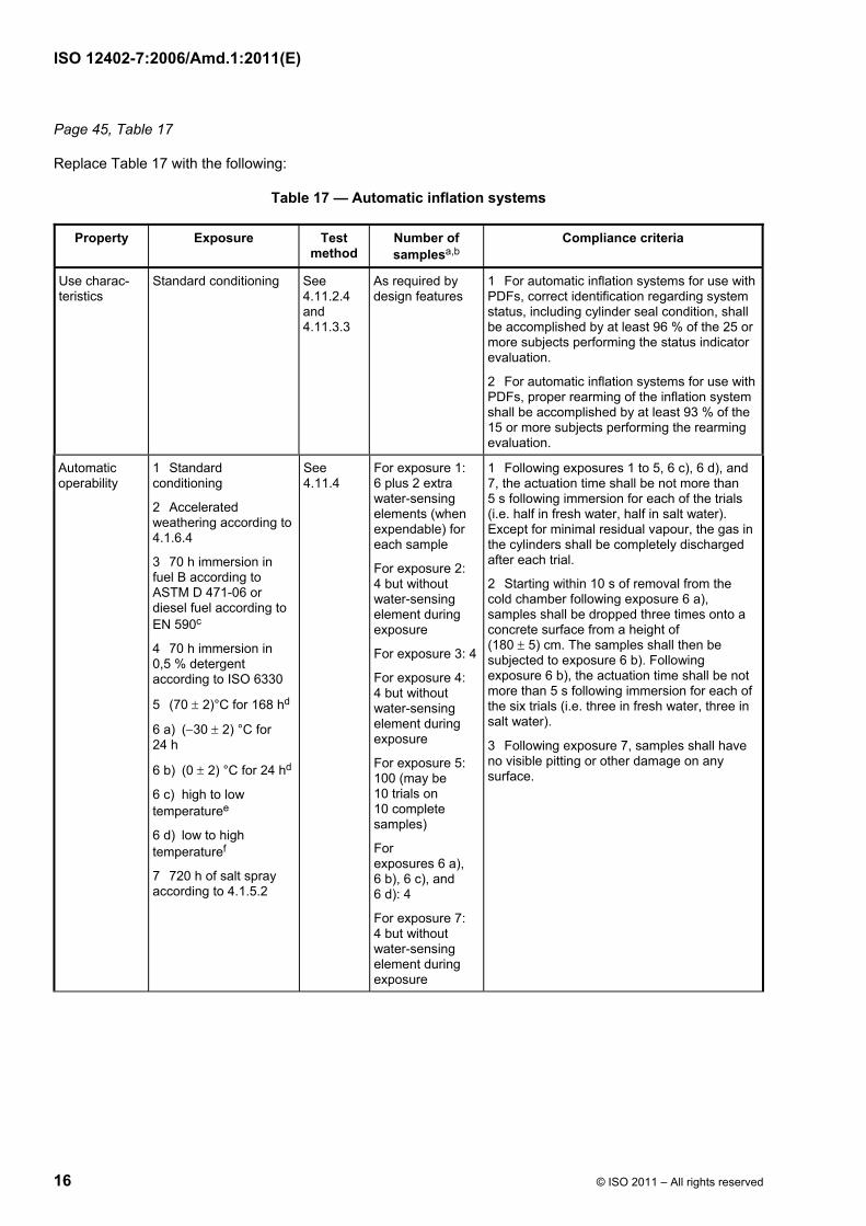
Replace Table 17 with the following:
Table 17 — Automatic inflation systems
Property Exposure Test method
Number of samplesa,b
Compliance criteria
Use charac-teristics
Standard conditioning See 4.11.2.4 and 4.11.3.3
As required by design features
1 For automatic inflation systems for use with PDFs, correct identification regarding system status, including cylinder seal condition, shall be accomplished by at least 96 % of the 25 or more subjects performing the status indicator evaluation.
2 For automatic inflation systems for use with PDFs, proper rearming of the inflation system shall be accomplished by at least 93 % of the 15 or more subjects performing the rearming evaluation.
Automatic operability
1 Standard conditioning
2 Accelerated weathering according to 4.1.6.4
3 70 h immersion in fuel B according to ASTM D 471-06 or diesel fuel according to EN 590c
4 70 h immersion in 0,5 % detergent according to ISO 6330
5 (70 ± 2)°C for 168 hd
6 a) (−30 ± 2) °C for 24 h
6 b) (0 ± 2) °C for 24 hd
6 c) high to low temperaturee
6 d) low to high temperaturef
7 720 h of salt spray according to 4.1.5.2
See 4.11.4
For exposure 1: 6 plus 2 extra water-sensing elements (when expendable) for each sample
For exposure 2: 4 but without water-sensing element during exposure
For exposure 3: 4
For exposure 4: 4 but without water-sensing element during exposure
For exposure 5: 100 (may be 10 trials on 10 complete samples)
For exposures 6 a), 6 b), 6 c), and 6 d): 4
For exposure 7: 4 but without water-sensing element during exposure
1 Following exposures 1 to 5, 6 c), 6 d), and 7, the actuation time shall be not more than 5 s following immersion for each of the trials (i.e. half in fresh water, half in salt water). Except for minimal residual vapour, the gas in the cylinders shall be completely discharged after each trial.
2 Starting within 10 s of removal from the cold chamber following exposure 6 a), samples shall be dropped three times onto a concrete surface from a height of (180 ± 5) cm. The samples shall then be subjected to exposure 6 b). Following exposure 6 b), the actuation time shall be not more than 5 s following immersion for each of the six trials (i.e. three in fresh water, three in salt water).
3 Following exposure 7, samples shall have no visible pitting or other damage on any surface.

ISO 12402-7:2006/Amd.1:2011(E)
© ISO 2011 – All rights reserved 17
Table 17 (continued)
Property Exposure Test method
Number of samplesa,b
Compliance criteria
Discharge Same as automatic operability exposures 1, 2, 3, 4, 5, 6 b), and 7
See 4.11.7 Three of the samples from exposures 1, 2, 4 and 7 from the automatic operability test with new water-sensing elements. Three new samples complete with water-sensing elements shall be used for exposures 3, 4, 5, 6 a) and 6 b)
For exposures 1 to 5, and 7, the time for actuation following immersion shall be not more than 5 s. In addition, systems shall achieve 100 % of nominal design buoyancy within 10 s following immersion. For exposure 6 b), the time for actuation following immersion shall be not more than 5 s. In addition, systems shall achieve 50 % of nominal design buoyancy within 10 s following immersion.
Hydrostatic proof pressure
Standard conditioning See 4.11.4 1 complete The inflation system shall withstand an internal hydrostatic pressure of (10 300 ± 300) kPa gauge without deformation or leakage.
Proof pressure Standard conditioning See 4.11.4 The sample from the hydrostatic proof pressure test
After the hydrostatic proof pressure test, the inflation system shall not leak when subjected to an air pressure of 14 kPa gauge for 30 s, followed by an air pressure of 275 kPa gauge for 30 s.
Air flow Standard conditioning See 4.11.4 1 complete The inflation system meets the intent of the requirement when minimum air flow is 4 l/min at an inlet pressure of 275 kPa gauge.
Vacuum Standard conditioning See 4.11.4 The sample from the air flow test
The inflation system shall not show a loss of pressure greater than 1,3 mm of water in 1 min or 2,5 mm of water in 1 h when subjected to a vacuum of 300 mm of water applied so as to reduce the seating spring pressure and with atmospheric pressure on the other side.
Humid atmosphere
Conditioning:g
168 h at (49 ± 2) °C and ( 2
096+ ) % relative humidity
See 4.11.8 100 complete (may be 2 trials on 50 complete samples)g
95 % of the sample shall not actuate during the exposure and shall operate as intended following the exposure. Those samples that did not actuate during the exposure shall completely pierce the proof disc within 5 s when immersed following the exposure.
System durability
Standard conditioning See 4.11.9 1 complete The inflation system shall operate as intended.
Pull Standard conditioning See 4.11.11 1 complete The inflation system shall not be damaged. a Applies for all colours. b For polymeric/metallic inflation systems, a minimum of 35 samples with water-sensing elements plus 300 extra water-sensing elements, plus 300 cylinders. c Exposure tests shall be based on typical fuels used in the intended area of application. d The duration specified is for the first trial. Each sample shall be conditioned for an additional 4 h prior each subsequent trial. e Each sample shall be placed in a circulating air oven maintained at (70 ± 2) °C for 24 h. The samples shall then to be placed in a cold chamber at (−30 ± 2) °C for 24 h. The temperature of the cold chamber shall then be raised to (0 ± 2) °C for 24 h. f Each sample shall be placed in a cold chamber at (−30 ± 2) °C for 24 h. The samples shall then be placed in a circulating air oven maintained at (70 ± 2) °C for 24 h. g The test samples shall be placed in an uninsulated, watertight enclosure and draped with a fabric prior to being transferred to the ambient condition and shall be removed from the enclosure upon return to the elevated temperature and humidity conditions. The fabric used shall have the same use as coated fabric as a material that can be used for the buoyancy compartment.

ISO 12402-7:2006/Amd.1:2011(E)
18 © ISO 2011 – All rights reserved
Page 47, Table 18
Replace Table 18 with the following:
Table 18 — Manual inflation systems
Property Exposure Test method
Number of samplesa,b
Compliance criteria
Use charac-teristics
Standard conditioning See 4.11.2.4and 4.11.3.3
As required by design features
1 For manual inflation systems, correct identification regarding system status, including cylinder seal condition, shall be accomplished by at least 96 % of the 25 or more subjects performing the status indicator evaluation.
2 For manual inflation systems, proper rearming of the inflation system shall be accomplished by at least 93 % of the 15 or more subjects performing the rearming evaluation.
Manual operability
1 Standard conditioning
2 Accelerated weathering according to 4.1.6.4
3 70 h immersion in fuel B according to ASTM D 471-06 or diesel fuel according to EN 590c
4 70 h immersion in 0,5 % detergent according to ISO 6330
5 (70 ± 2) °C for 168 hd
6 (−30 ± 2) °C for 24 hd
7 720 h of salt spray according to 4.1.5.2
See 4.11.5 3 for each separate condi-tioning (total 27 samples)
1 Following exposures 1 to 5 and 7, the force applied to the toggle resulting in piercing shall be not less than 13 N and not more than 67 N for each of the trials, and the average force shall be not less than 22 N.
2 Within 10 s of removal from the cold chamber following exposure 6, samples shall remain operable when dropped three times onto a concrete surface from a height of 180 cm. The force applied to the toggle resulting in piercing shall be not less than 13 N and not more than 67 N for each of the trials, and the average force shall be not less than 22 N.
3 Following exposure 7, samples shall have no visible pitting or other damage on any surface.
Pull cord strength
1 Standard conditioning
2 Accelerated weathering according to 4.1.6.4
See 4.11.5 1 for each separate conditioning
NOTE Use of operability test samples is an alternative.
The pull cord, its attachment to the tab and its attachment to the inflator shall withstand a force of 445 N for 3 s without failing or separating from the inflator.
Hydrostatic proof pressure
Standard conditioning
See 4.11.5 1 complete The inflation system shall withstand an internal hydrostatic pressure of 10 300 kPa without deformation or leakage.
Proof pressure
Standard conditioning
See com-pliance criteria
The sample from the hydrostatic proof pressure test
After the hydrostatic proof pressure test, the inflation system shall not leak when subjected to an air pressure of 14 kPa gauge for 30 s, followed by an air pressure of 275 kPa gauge for 30 s.

ISO 12402-7:2006/Amd.1:2011(E)
© ISO 2011 – All rights reserved 19
Table 18 (continued)
Property Exposure Test method
Number of samplesa,b
Compliance criteria
Air flow Standard conditioning See com-pliance criteria
1 complete The inflation system shall allow a minimum air flow of 4 l/min at an inlet pressure of 275 kPa gauge.
Vacuum Standard conditioning See com-pliance criteria
The sample from the air flow test
The inflation system shall not show a loss of pressure greater than 1,3 mm of water in 1 min or 2,5 mm of water in 1 h when subjected to a vacuum of 300 mm of water applied so as to reduce the seating spring pressure and with atmospheric pressure on the other side.
System durability
Standard conditioning See 4.11.9 1 complete sample
The inflation system shall operate as intended.
Pull Standard conditioning See 4.11.11 1 The inflation system shall not be damaged.
a Applies for all colours.
b For polymeric/metallic inflation systems, a minimum of 35 samples, and 300 cylinders.
c Exposure tests shall be based on typical fuels used in the intended area of application.
d The duration specified is for the first trial. Each sample shall be conditioned for 4 h prior to each subsequent trial.

ISO 12402-7:2006/Amd.1:2011(E)
20 © ISO 2011 – All rights reserved
Page 48, Table 19
Replace Table 19 with the following:
Table 19 — Oral inflation systems
Property Exposure Test method
Number of samplesa,b
Compliance criteria
Oral operability
1 Standard conditioning
2 Accelerated weathering according to 4.1.6.4
3 70 h immersion in fuel B according to ASTM D 471-06 or diesel fuel according to EN 590c
4 70 h immersion in 0,5 % detergent according to ISO 6330
5 (70 ± 2) °C for 168 h
6 (−30 ± 2) °C for 24 h
7 720 h of salt spray according to 4.1.5.2
See 4.11.6 3 for each separate conditioning (total 27 samples)
1 The crack pressure shall not exceed 3 kPa.
2 The air flow shall be not less than 100 l/min at 7 kPa gauge pressure.
Back-pressure
Same as oral operability See com-pliance criteria
The samples from the operability test
The samples shall not leak when subjected to a back-pressure of 0 kPa to 69 kPa.
When leakage occurs using samples from the salt spray exposure or detergent exposure, rinse the valve from the outside by agitating the sample in fresh water for a period of not more than 15 s to dissolve any embedded particles, and repeat the test.
a Applies for all colours.
b For polymeric/metallic inflation systems, a minimum of 30 samples.
c Exposure tests shall be based on typical fuels used in the intended area of application.
ISO 12402-7:2006/Amd.1:2011(E)
© ISO 2011 – All rights reserved 21
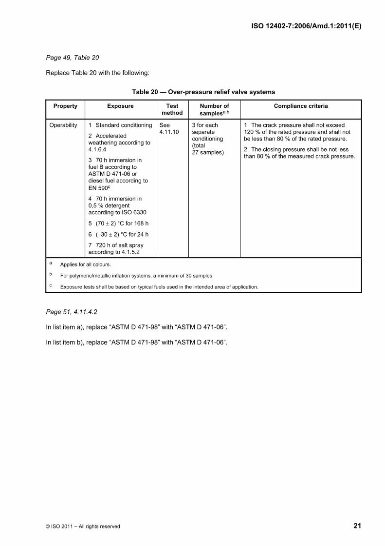
Page 49, Table 20
Replace Table 20 with the following:
Table 20 — Over-pressure relief valve systems
Property Exposure Test method
Number of samplesa,b
Compliance criteria
Operability 1 Standard conditioning
2 Accelerated weathering according to 4.1.6.4
3 70 h immersion in fuel B according to ASTM D 471-06 or diesel fuel according to EN 590c
4 70 h immersion in 0,5 % detergent according to ISO 6330
5 (70 ± 2) °C for 168 h
6 (−30 ± 2) °C for 24 h
7 720 h of salt spray according to 4.1.5.2
See 4.11.10
3 for each separate conditioning (total 27 samples)
1 The crack pressure shall not exceed 120 % of the rated pressure and shall not be less than 80 % of the rated pressure.
2 The closing pressure shall be not less than 80 % of the measured crack pressure.
a Applies for all colours.
b For polymeric/metallic inflation systems, a minimum of 30 samples.
c Exposure tests shall be based on typical fuels used in the intended area of application.
Page 51, 4.11.4.2
In list item a), replace “ASTM D 471-98” with “ASTM D 471-06”.
In list item b), replace “ASTM D 471-98” with “ASTM D 471-06”.

ISO 12402-7:2006/Amd.1:2011(E)
ICS 13.340.70 Price based on 21 pages
© ISO 2011 – All rights reserved
Reference numberISO 12402-7:2006(E)
© ISO 2006
INTERNATIONAL STANDARD
ISO12402-7
First edition2006-11-15
Personal flotation devices — Part 7: Materials and components — Safety requirements and test methods
Équipements individuels de flottabilité —
Partie 7: Matériaux et composants — Exigences de sécurité et méthodes d'essai

ISO 12402-7:2006(E)
PDF disclaimer This PDF file may contain embedded typefaces. In accordance with Adobe's licensing policy, this file may be printed or viewed but shall not be edited unless the typefaces which are embedded are licensed to and installed on the computer performing the editing. In downloading this file, parties accept therein the responsibility of not infringing Adobe's licensing policy. The ISO Central Secretariat accepts no liability in this area.
Adobe is a trademark of Adobe Systems Incorporated.
Details of the software products used to create this PDF file can be found in the General Info relative to the file; the PDF-creation parameters were optimized for printing. Every care has been taken to ensure that the file is suitable for use by ISO member bodies. In the unlikely event that a problem relating to it is found, please inform the Central Secretariat at the address given below.
© ISO 2006 All rights reserved. Unless otherwise specified, no part of this publication may be reproduced or utilized in any form or by any means, electronic or mechanical, including photocopying and microfilm, without permission in writing from either ISO at the address below or ISO's member body in the country of the requester.
ISO copyright office Case postale 56 • CH-1211 Geneva 20 Tel. + 41 22 749 01 11 Fax + 41 22 749 09 47 E-mail [email protected] Web www.iso.org
Published in Switzerland
ii © ISO 2006 – All rights reserved

ISO 12402-7:2006(E)
© ISO 2006 – All rights reserved iii
Contents Page
Foreword............................................................................................................................................................ iv Introduction ........................................................................................................................................................ v 1 Scope ..................................................................................................................................................... 1 2 Normative references ........................................................................................................................... 1 3 Terms and definitions........................................................................................................................... 3 4 Materials and components .................................................................................................................. 5 4.1 General................................................................................................................................................... 5 4.2 Sewing thread ....................................................................................................................................... 7 4.3 Fabric ..................................................................................................................................................... 8 4.4 Structural webbing and tie tape ........................................................................................................ 13 4.5 Structural lacing.................................................................................................................................. 15 4.6 Structural zippers ............................................................................................................................... 15 4.7 Hardware.............................................................................................................................................. 18 4.8 Foam flotation material ...................................................................................................................... 24 4.9 Inflation chamber materials ............................................................................................................... 32 4.10 Polymeric foam coatings ................................................................................................................... 36 4.11 Inflation systems for hybrid and fully inflatable PFDs.................................................................... 41 4.12 Gas-filled cylinders............................................................................................................................. 57 Annex A (informative) Mildew resistance of materials: Soil burial method ............................................... 73 Annex B (informative) Abrasion resistance of cloth: Oscillatory method (Wyzenbeek method) ............ 75 Annex C (informative) Example of a design drawing ................................................................................... 78 Bibliography ..................................................................................................................................................... 79

ISO 12402-7:2006(E)
iv © ISO 2006 – All rights reserved
Foreword
ISO (the International Organization for Standardization) is a worldwide federation of national standards bodies (ISO member bodies). The work of preparing International Standards is normally carried out through ISO technical committees. Each member body interested in a subject for which a technical committee has been established has the right to be represented on that committee. International organizations, governmental and non-governmental, in liaison with ISO, also take part in the work. ISO collaborates closely with the International Electrotechnical Commission (IEC) on all matters of electrotechnical standardization.
International Standards are drafted in accordance with the rules given in the ISO/IEC Directives, Part 2.
The main task of technical committees is to prepare International Standards. Draft International Standards adopted by the technical committees are circulated to the member bodies for voting. Publication as an International Standard requires approval by at least 75 % of the member bodies casting a vote.
Attention is drawn to the possibility that some of the elements of this document may be the subject of patent rights. ISO shall not be held responsible for identifying any or all such patent rights.
ISO 12402-7 was prepared by the European Committee for Standardization (CEN) Technical Committee CEN/TC 162, Protective clothing including hand and arm protection and lifejackets, in collaboration with Technical Committee ISO/TC 188, Small craft, in accordance with the Agreement on technical cooperation between ISO and CEN (Vienna Agreement).
ISO 12402 consists of the following parts, under the general title Personal flotation devices:
⎯ Part 1: Lifejackets for seagoing ships — Safety requirements
⎯ Part 2: Lifejackets, performance level 275 — Safety requirements
⎯ Part 3: Lifejackets, performance level 150 — Safety requirements
⎯ Part 4: Lifejackets, performance level 100 — Safety requirements
⎯ Part 5: Buoyancy aids (level 50) — Safety requirements
⎯ Part 6: Special purpose lifejackets and buoyancy aids — Safety requirements and additional test methods
⎯ Part 7: Materials and components — Safety requirements and test methods
⎯ Part 8: Accessories — Safety requirements and test methods
⎯ Part 9: Test methods
⎯ Part 10: Selection and application of personal flotation devices and other relevant devices
ISO 12402-7:2006(E)
© ISO 2006 – All rights reserved v
Introduction
ISO 12402 has been prepared to give guidance on the design and application of personal flotation devices (hereafter referred to as PFDs) for persons engaged in activities, whether in relation to their work or their leisure, in or near water. PFDs manufactured, selected, and maintained to this standard should give a reasonable assurance of safety from drowning to a person who is immersed in water.
Requirements for lifejackets on large, commercial seagoing ships are regulated by the International Maritime Organization (IMO) under the International Convention for the Safety of Life at Sea (SOLAS). ISO 12402-1 addresses lifejackets for seagoing ships.
ISO 12402 allows for the buoyancy of a PFD to be provided by a wide variety of materials or designs, some of which may require preparation before entering the water (e.g. inflation of chambers by gas from a cylinder or blown in orally). However, PFDs can be divided into the following two main classes:
⎯ those which provide face up in-water support to the user regardless of physical conditions (lifejackets), and
⎯ those which require the user to make swimming and other postural movements to position the user with the face out of the water (buoyancy aids).
Within these main two classes there are a number of levels of support, types of buoyancy, activation methods for inflatable devices, and auxiliary items (such as location aids), all of which will affect the user’s probability of survival. Within the different types of buoyancy allowed, inflatable PFDs either provide full buoyancy without any user intervention other than arming (i.e. PFDs inflated by a fully automatic method) or require the user to initiate the inflation. Hybrid PFDs always provide some buoyancy but rely on the same methods as inflatable PFDs to achieve full buoyancy. With inherently buoyant PFDs, the user only needs to put the PFD on to achieve the performance of its class.
PFDs that do not require intervention (automatically operating PFDs) are suited to activities where persons are likely to enter the water unexpectedly; whereas PFDs requiring intervention (e.g. manually inflated PFDs) are only suitable for use if the user believes there will be sufficient time to produce full buoyancy, or help is close at hand. In every circumstance, the user should ensure that the operation of the PFD is suited to the specific application. The conformity of a PFD to this part of ISO 12402 does not imply that it is suitable for all circumstances. The relative amount of required inspection and maintenance is another factor of paramount importance in the choice and application of specific PFDs.
ISO 12402 is intended to serve as a guide to manufacturers, purchasers, and users of such safety equipment in ensuring that the equipment provides an effective standard of performance in use. Equally essential is the need for the designer to encourage the wearing of the equipment by making it comfortable and attractive for continuous wear on or near water, rather than for it to be stored in a locker for emergency use. Throwable devices and flotation cushions are not covered by this part of ISO 12402. The primary function of a PFD is to support the user in reasonable safety in the water. Within the two classes, alternative attributes make some PFDs better suited to some circumstances than others or make them easier to use and care for than others. Important alternatives allowed by ISO 12402 are the following:
⎯ to provide higher levels of support (levels 100, 150, or 275) that generally float the user with greater water clearance, enabling the user’s efforts to be expended in recovery rather than avoiding waves; or to provide lighter or less bulky PFDs (levels 50 to 100);
⎯ to provide the kinds of flotation (inherently buoyant foam, hybrid, and inflatable) that will accommodate the sometimes conflicting needs of reliability and durability, in-water performance, and continuous wear;

ISO 12402-7:2006(E)
vi © ISO 2006 – All rights reserved
⎯ to provide automatically operating (inherently buoyant or automatically inflated) PFDs that float users without any intervention on their part, except in initially donning the PFD (and regular inspection and rearming of inflatable types), or to provide user control of the inflatable PFD’s buoyancy by manual and oral operation; and
⎯ to assist in detection (location aids) and recovery of the user.
PFDs provide various degrees of buoyancy in garments that are light in weight and only as bulky and restrictive as needed for their intended use. They will need to be secure when worn, in order to provide positive support in the water and to allow the user to swim or actively assist herself/himself or others. The PFD selected shall ensure that the user is supported with the mouth and nose clear of the water under the expected conditions of use and the user’s ability to assist.
Under certain conditions (such as rough water and waves), the use of watertight and multilayer clothing, which provide (intentionally or otherwise) additional buoyancy, or the use of equipment with additional weight (such as tool belts) will likely alter the performance of the PFD. Users, owners and employers need to ensure that this is taken into account when selecting a PFD. Similarly, PFDs may not perform as well in extremes of temperature, although fully approved under this part of ISO 12402. PFDs may also be affected by other conditions of use, such as chemical exposure and welding, and may require additional protection to meet the specific requirements of use. If the user intends taking a PFD into such conditions, she/he has to be assured that the PFD will not be adversely affected. This part of ISO 12402 also allows a PFD to be an integral part of a safety harness designed to conform to ISO 12401, or an integral part of a garment with other uses, for example to provide thermal protection during immersion, in which case the complete assembly as used is required to conform to this part of ISO 12402.
In compiling the attributes required of a PFD, consideration has also been given to the potential length of service that the user might expect. Whilst a PFD needs to be of substantial construction and material, its potential length of service often depends on the conditions of use and storage, which are the responsibility of the owner, user and/or employer. Furthermore, whilst the performance tests included are believed to assess relevant aspects of performance in real-life use, they do not accurately simulate all conditions of this. For example, the fact that a device passes the self-righting tests in swimming attire, as described herein, does not guarantee that it will self-right an unconscious user wearing waterproof clothing; neither can it be expected to completely protect the airway of an unconscious person in rough water. Waterproof clothing can trap air and further impede the self-righting action of a lifejacket.
It is essential that owners, users and employers choose those PFDs that meet the correct standards for the circumstances in which they will be used. Manufacturers and those selling PFDs have to make clear to prospective purchasers the product properties, alternative choices and the limitations to normal use, prior to the purchase.
Similarly, those framing legislation regarding the use of these garments should consider carefully which class and performance levels are most appropriate for the foreseeable conditions of use, allowing for the higher risk circumstances. These higher risk circumstances should account for the highest probabilities of occurrence of accidental immersion and the expected consequences in such emergencies. More information on the selection and application is given in ISO 12402-10.

INTERNATIONAL STANDARD ISO 12402-7:2006(E)
© ISO 2006 – All rights reserved 1
Personal flotation devices —
Part 7: Materials and components — Safety requirements and test methods
1 Scope
This part of ISO 12402 specifies the minimum requirements for construction and performance of materials and components of personal flotation devices as well as relevant test methods.
2 Normative references
The following referenced documents are indispensable for the application of this document. For dated references, only the edition cited applies. For undated references, the latest edition of the referenced document (including any amendments) applies.
ISO 31 (all parts), Quantities and units
ISO 105-A02, Textiles — Tests for colour fastness — Part A02: Grey scale for assessing change in colour
ISO 105-B02:1994, Textiles — Tests for colour fastness — Part B02: Colour fastness to artificial light: Xenon arc fading lamp test
ISO 105-E02, Textiles — Tests for colour fastness — Part E02: Colour fastness to sea water
ISO 105-X12, Textiles — Tests for colour fastness — Part X12: Colour fastness to rubbing
ISO 139, Textiles — Standard atmospheres for conditioning and testing
ISO 188, Rubber, vulcanized or thermoplastic — Accelerated ageing and heat resistance tests
ISO 1302, Geometrical Product Specifications (GPS) — Indication of surface texture in technical product documentation
ISO 1421:1998, Rubber- or plastics-coated fabrics — Determination of tensile strength and elongation at break
ISO 1926, Rigid cellular plastics — Determination of tensile properties
ISO 2062, Textiles — Yarns from packages — Determination or single-end breaking force and elongation at break
ISO 2411:2000, Rubber- or plastics-coated fabrics — Determination of coating adhesion
ISO 3696:1987, Water for analytical laboratory use — Specification and test methods
ISO 4674-1:2003, Rubber- or plastics-coated fabrics — Determination of tear resistance — Part 1: Constant rate of tear methods
ISO 12402-7:2006(E)
2 © ISO 2006 – All rights reserved
ISO 4892-1, Plastics — Methods of exposure to laboratory light sources — Part 1: General guidance
ISO 4892-2, Plastics — Methods of exposure to laboratory light sources — Part 2: Xenon-arc lamps
ISO 5470-2:2003, Rubber- or plastics-coated fabrics — Determination of abrasion resistance — Part 2: Martindale abrader
ISO 6330, Textiles — Domestic washing and drying procedures for textile testing
ISO 7229, Rubber- or plastics-coated fabrics — Measurement of gas permeability
ISO 7854:1995, Rubber- or plastics-coated fabrics — Determination of resistance to damage by flexing
ISO 9073-4, Textiles — Test methods for nonwovens — Part 4: Determination of tear resistance
ISO 9227, Corrosion tests in artificial atmospheres — Salt spray tests
ISO 12402-1, Personal flotation devices — Part 1: Lifejackets for seagoing ships — Safety requirements
ISO 12402-2, Personal flotation devices — Part 2: Lifejackets, performance level 275 — Safety requirements
ISO 12402-3, Personal flotation devices — Part 3: Lifejackets, performance level 150 — Safety requirements
ISO 12402-4, Personal flotation devices — Part 4: Lifejackets, performance level 100 — Safety requirements
ISO 12402-5, Personal flotation devices — Part 5: Buoyancy aids (level 50) — Safety requirements
ISO 12402-6, Personal flotation devices — Part 6: Special purpose lifejackets and buoyancy aids — Safety requirements and additional test methods
ISO 12947-2, Textiles — Determination of the abrasion resistance of fabrics by the Martindale method — Part 2: Determination of specimen breakdown
ISO 13934-1, Textiles — Tensile properties of fabrics — Part 1: Determination of maximum force and elongation at maximum force using the strip method
ISO 13934-2, Textiles — Tensile properties of fabrics — Part 2: Determination of maximum force using the grab method
ISO 13937-2, Textiles — Tear properties of fabrics — Part 2: Determination of tear force of trouser-shaped test specimens (Single tear method)
ISO 13938-1, Textiles — Bursting properties of fabrics — Part 1: Hydraulic method for determination of bursting strength and bursting distension
ISO 13938-2, Textiles — Bursting properties of fabrics — Part 2: Pneumatic method for determination of bursting strength and bursting distension
EN 590, Automotive fuels — Diesel — Requirements and test methods
EN 10088-1, Stainless steels — Part 1: List of stainless steels
CIE publication No. 15.2, Colorimetry
ASTM D 412-98, Standard Test Methods for Vulcanized Rubber and Thermoplastic Elastomers —Tension
ASTM D 471-98, Standard Test Method for Rubber Property-Effect of Liquids
ASTM D 882-02, Standard Test Method for Tensile Properties of Thin Plastic Sheeting

ISO 12402-7:2006(E)
© ISO 2006 – All rights reserved 3
ASTM D 1683, Standard Test Method for Failure in Sewn Seams of Woven Apparel Fabrics
ASTM D 2061, Standard Test Methods for Strength Tests for Zippers
ASTM D 2062, Standard Test Methods for Operability of Zippers
ASTM D 5034-95, Standard Test Method for Breaking Strength and Elongation of Textile Fabrics (Grab Test)
FTMS 191A, Federal Test Method Standard
3 Terms and definitions
For the purposes of this document, the terms and definitions given in ISO 12402-1 to ISO 12402-5 and the following apply.
3.1 coated fabric flexible material composed of a textile fabric and an adherent polymeric material
3.2 course series of successive loops lying crosswise in knitted fabrics, that is, lying at right angles to a line passing through the open throat to the closed end of the loops
3.3 cylinder seal indicator visual display on an inflation system which provides information regarding the status of the seal on an installed cylinder
3.4 design inflation range range of buoyancy and pressure, as specified by the manufacturer, to which a chamber is capable of being inflated to provide the intended in-water performance
3.5 weft yarn running from selvage to selvage at right angles to the warp in woven fabrics
NOTE For knitted fabric, see 3.21.
3.6 filling density mass of the gas charge for gas-filled cylinders or other inflation-medium containers, in kilograms, divided by the volume of the inflation-medium container, in litres
3.7 foam flotation material closed-cell (cells not interconnecting) foamed polymeric material
3.8 full inflation chamber or chambers inflated to any value within the design inflation range
3.9 inflation system means of inflating one or more chambers to make the PFD buoyant or more buoyant on demand, either actively or passively with respect to the user’s action

ISO 12402-7:2006(E)
4 © ISO 2006 – All rights reserved
3.10 initial jaw separation distance between the bottom of the top clamp and the top of the bottom clamp of a tensile test machine prior to testing
3.11 laminated fabric layered fabric structure wherein a fabric is combined with a continuous sheet material, either by heat or by an adhesive, in such a way that the identity of the continuous sheet material is retained
3.12 lot number marking assigned to each group of materials or component produced which incorporates a means of identifying the year and quarter of manufacture (unless provided elsewhere), and provides a means of identifying the production of a particular factory when a manufacturer produces at more than one factory
3.13 multi-eyelet guide polymeric part designed to be sewn into a PFD and having a series of holes to insert lacing for adjustment of the fit of a PFD
3.14 multi-point status indicator status indicator which utilizes two or more independent visual display points to communicate inflation system readiness
3.15 polymeric foam coating coating applied to flotation foam in place of a fabric covering to protect and strengthen the finished PFD
3.16 selvage uncut edge portion of a fabric
3.17 serviceability ease with which the inflation system mechanism is properly rearmed
3.18 serviceable capable of continued use, i.e. exhibits no signs of functional deterioration, broken or deformed hardware, non-functional indicators, blocked or detached oral inflation tube, or detached manual inflator trigger
3.19 single-point status indicator status indicator which combines all system checks into a single visual display point to communicate inflation system readiness
3.20 status indicator part or parts of an inflation system which provide user feedback to assist in keeping an inflatable PFD in an armed and ready condition
3.21 wale column of loops in successive courses in knitted fabrics, which is parallel to the loop axes
ISO 12402-7:2006(E)
© ISO 2006 – All rights reserved 5
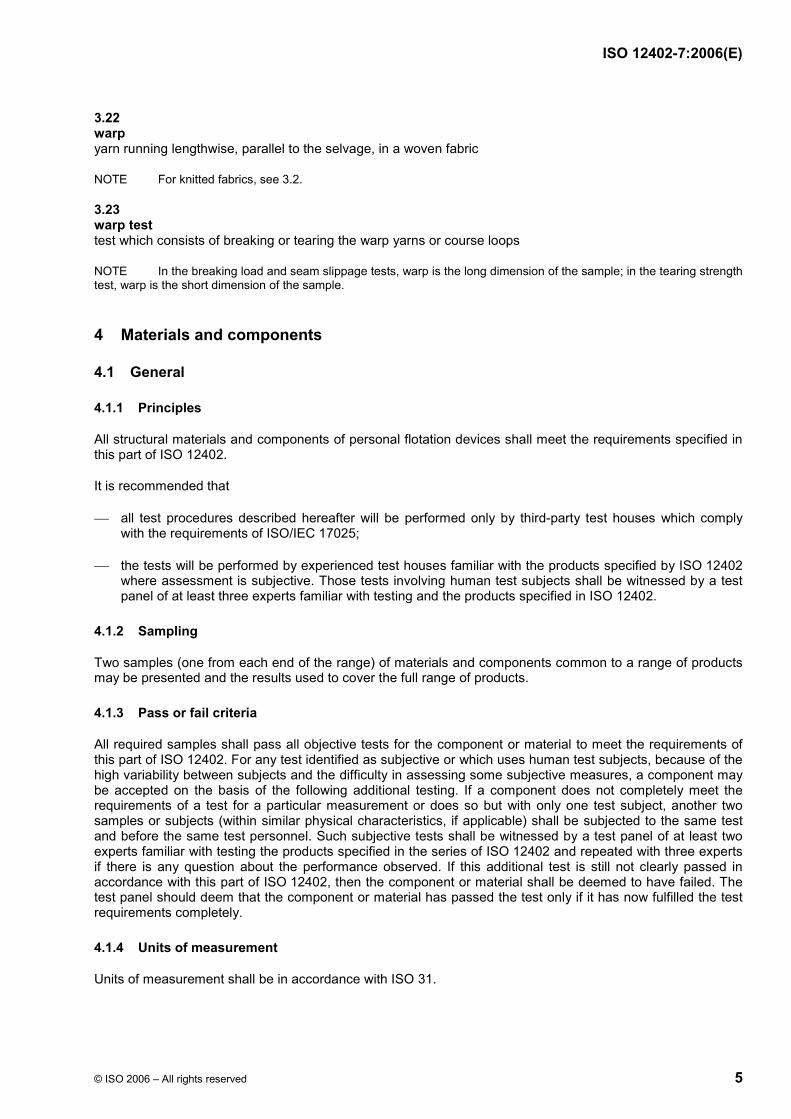
3.22 warp yarn running lengthwise, parallel to the selvage, in a woven fabric
NOTE For knitted fabrics, see 3.2.
3.23 warp test test which consists of breaking or tearing the warp yarns or course loops
NOTE In the breaking load and seam slippage tests, warp is the long dimension of the sample; in the tearing strength test, warp is the short dimension of the sample.
4 Materials and components
4.1 General
4.1.1 Principles
All structural materials and components of personal flotation devices shall meet the requirements specified in this part of ISO 12402.
It is recommended that
⎯ all test procedures described hereafter will be performed only by third-party test houses which comply with the requirements of ISO/IEC 17025;
⎯ the tests will be performed by experienced test houses familiar with the products specified by ISO 12402 where assessment is subjective. Those tests involving human test subjects shall be witnessed by a test panel of at least three experts familiar with testing and the products specified in ISO 12402.
4.1.2 Sampling
Two samples (one from each end of the range) of materials and components common to a range of products may be presented and the results used to cover the full range of products.
4.1.3 Pass or fail criteria
All required samples shall pass all objective tests for the component or material to meet the requirements of this part of ISO 12402. For any test identified as subjective or which uses human test subjects, because of the high variability between subjects and the difficulty in assessing some subjective measures, a component may be accepted on the basis of the following additional testing. If a component does not completely meet the requirements of a test for a particular measurement or does so but with only one test subject, another two samples or subjects (within similar physical characteristics, if applicable) shall be subjected to the same test and before the same test personnel. Such subjective tests shall be witnessed by a test panel of at least two experts familiar with testing the products specified in the series of ISO 12402 and repeated with three experts if there is any question about the performance observed. If this additional test is still not clearly passed in accordance with this part of ISO 12402, then the component or material shall be deemed to have failed. The test panel should deem that the component or material has passed the test only if it has now fulfilled the test requirements completely.
4.1.4 Units of measurement
Units of measurement shall be in accordance with ISO 31.

ISO 12402-7:2006(E)
6 © ISO 2006 – All rights reserved
4.1.5 Material
4.1.5.1 Non-metallic components and fabrics
Non-metallic components and fabrics shall not be damaged by storage at temperatures of −30 °C to +65 °C.
4.1.5.2 Corrosion of metal components
When tested in accordance with ISO 9227 for a period of 160 h, metal components shall not be significantly affected by corrosion. This shall be tested according to the relevant clauses of this part of ISO 12402.
4.1.5.3 Magnetic properties
No metallic component shall affect a magnetic compass of a type commonly used in small boats by more than 1° when placed 500 mm from the compass.
4.1.5.4 Innocuousness
The foam flotation material shall not contain CFC or HCFC.
4.1.6 Sample conditioning
4.1.6.1 General
Materials and components common to a range of products may be presented as one sample of each item.
Prior to testing, materials and components shall be conditioned.
4.1.6.2 Standard conditioning
a) Except for textile products (i.e., fabric, webbing, thread, tie tape), the applicable number of samples specified in each section shall be conditioned at (23 ± 2) °C and (50 ± 5) % relative humidity for not less than 24 h prior to the tests.
b) For textile products, the samples shall be conditioned according to ISO 139 for not less than 24 h.
c) If it is spelled out that the sample is to be tested under “wet conditions”, the sample shall be soaked for 6 0,2
0+ h in fresh water, or as specified by the test procedure itself.
4.1.6.3 Temperature cycling
Where required by the test method, the component or sample of fabric shall be conditioned, in its normal storage state, and then immediately exposed for (24,0 ± 0,5) h at a temperature of (−30 ± 2) °C, then for (24,0 ± 0,5) h at a temperature of (65 ± 2)°C. Any damage shall be assessed by visual examination and be reported. The component or sample shall undergo ten cycles.
4.1.6.4 Accelerated weathering
Laboratory exposure of components and fabrics for PFDs to conditions representative of elements found in a severe outdoor environment including light and water shall be conducted by exposing samples in a xenon weathering machine in accordance with ISO 4892-1 and ISO 4892-2 as further defined by the following specifications.
⎯ Exposure: 500 kJ/(m2 × nm) at 340 nm of UV radiation.

ISO 12402-7:2006(E)
© ISO 2006 – All rights reserved 7
⎯ Sample mounting: mount samples with the face side (the side normally exposed to sunlight in service) toward the light so that the centre of each sample is in the same plane as the perpendicular to the centreline of the light source.
⎯ Irradiance: 0,55 W/m2 at 340 nm.
⎯ Filters: daylight filters.
⎯ Black panel temperature: (63 ± 2) °C.
⎯ Dry bulb temperature: (42 ± 2) °C.
⎯ Relative humidity: 50 % (during light-only cycle).
⎯ Water temperature: (20 ± 5) °C.
⎯ Test cycles: 102 min of light/18 min of light and continuous water spray/24 min dark and water spray.
4.2 Sewing thread
4.2.1 Construction
Sewing thread shall not contain natural fibres or be monofilament.
4.2.2 Performance
Sewing thread shall comply with the requirements specified in Table 1.
4.2.3 Loop breaking strength
For the loop breaking strength test, the test machine described in ISO 2062 shall be used. Secure both ends of one piece in one clamp of the testing machine so that the length of the loop equals half the total length between the jaws. Pass one end of the second piece through the loop formed by the first, and secure both ends of the second piece in the other clamp of the machine. Separate the clamps at a rate of (300 ± 10) mm/min.
Table 1 — Sewing thread
Property Exposure Test method
Number of samples
Sample size a mm
Compliance criteria
Single strand breaking
1 Standard conditioning
2 Accelerated weathering according to 4.1.6.4
ISO 2062 5 for each colour for each exposure
1 000 ± 10 For exposure 1, the average breaking strength of five samples shall be at least 25 N. For exposure 2, the average breaking strength of five samples shall retain at least 60 % of the strength determined following standard conditioning. In addition, the average breaking strength of five samples shall be at least 23 N.
Loop breaking strength
Standard conditioning a
See 4.2.3 5 (each consisting of two pieces)
500 min. Average breaking strength of five samples shall be at least 44 N.
a Applies to each colour.

ISO 12402-7:2006(E)
8 © ISO 2006 – All rights reserved
4.3 Fabric
4.3.1 General
Only fabrics which are structural to maintain the performance of the product under test shall be tested. Decorative and other fabrics shall not be tested.
4.3.2 Performance
4.3.2.1 Fabric used as drainage material shall comply with all of the applicable fabric requirements. Following weathering according to 4.1.6, the tensile strength shall be measured using the grab method given in ISO 13934-2.
4.3.2.2 Textile woven fabrics shall have an as received tensile strength of at least 400 N, measured using the grab method given in ISO 13934-2.
4.3.2.3 Textile knitted fabrics shall have an as received tensile strength of at least 400 N, measured using the grab method given in ISO 13934-2.
4.3.2.4 Fabrics used in the construction of covers of buoyant compartments, the retention system, and any other component the failure of which would render the PFD non-conformant with this part of ISO 12402, shall comply with the following requirements.
a) Tensile strength for woven fabrics shall be tested according to ISO 13934-2 using the grab method, following conditioning according to 4.1.6, and shall have the strength given in Table 2,
b) Tear resistance of woven fabrics shall be tested according to ISO 13937-2, [tensile speed (100 ± 10) mm/min, with a pretension of 2 N for materials of up to 200 g/m2, 5 N for materials of over 200 g/m2 and up to 500 g/m2, and 10 N for materials of over 500 g/m2], and shall be not less than 35 N.
4.3.2.5 Fabric shall comply with the acceptance criteria specified in Table 2 when subjected to the tests therein. Separate samples shall be used for each different conditioning exposure.

ISO 12402-7:2006(E)
© ISO 2006 – All rights reserved 9
Table 2 — Fabric
Property Exposure Test method Number of samples
Sample size a
(mm) Compliance criteria
Tensile strength (woven fabrics only)
1 Standard conditioning 2 Accelerated weathering according to 4.1.6.4 3 70 h immersion in: 3.1 fuel B according to ASTM D 471-98 or diesel fuel according to EN 590 3.2 IRM 902 oil according to ASTM D 471-98 3.3 0,5 % detergent according to ISO 6330
ISO 13934-2 5 warp and 5 weft for each separate exposure
As specified by test method
Following each separate exposure in 1 and 2, the average of five samples shall be at least 400 N for each direction. Following exposures 2 and 3, the average of five samples shall retain at least 60 % of the strength determined following standard conditioning. Following exposure 2, the average of five samples shall be at least 290 N.
Burst (knitted fabrics only)
1 Standard conditioning 2 Accelerated weathering according to 4.1.6.4 3 70 h immersion in: 3.1 fuel B according to ASTM D 471-98 or diesel fuel according to EN 590 3.2 IRM 902 oil according to ASTM D 471-98 3.3 0,5 % detergent according to ISO 6330
ISO 13938-1 orISO 13938-2
10 for each separate exposure
130 × 130 Following each separate exposure in 1 and 2, the average of 10 samples shall be at least 800 kPa. Following exposure 3, the average of 10 samples shall retain at least 60 % of the strength determined following standard conditioning.
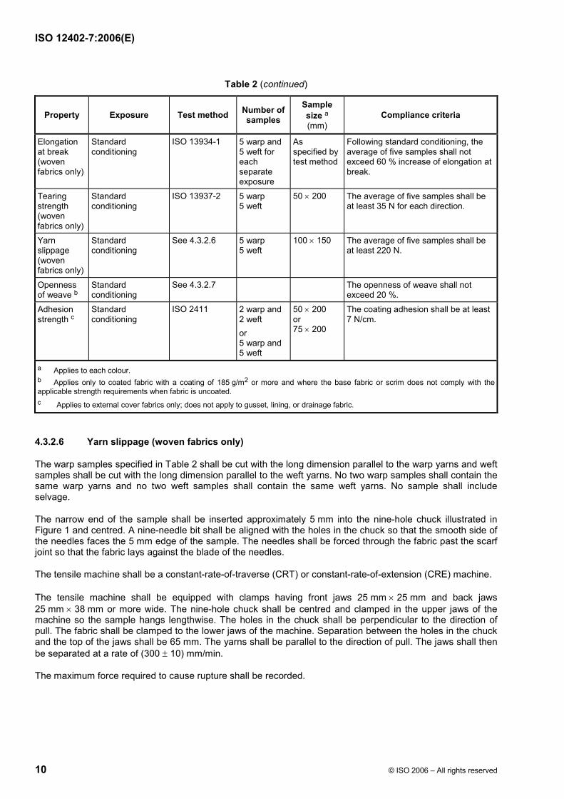
ISO 12402-7:2006(E)
10 © ISO 2006 – All rights reserved
Table 2 (continued)
Property Exposure Test method Number of samples
Sample size a
(mm) Compliance criteria
Elongation at break (woven fabrics only)
Standard conditioning
ISO 13934-1 5 warp and 5 weft for each separate exposure
As specified by test method
Following standard conditioning, the average of five samples shall not exceed 60 % increase of elongation at break.
Tearing strength (woven fabrics only)
Standard conditioning
ISO 13937-2 5 warp 5 weft
50 × 200 The average of five samples shall be at least 35 N for each direction.
Yarn slippage (woven fabrics only)
Standard conditioning
See 4.3.2.6 5 warp 5 weft
100 × 150 The average of five samples shall be at least 220 N.
Openness of weave b
Standard conditioning
See 4.3.2.7 The openness of weave shall not exceed 20 %.
Adhesion strength c
Standard conditioning
ISO 2411 2 warp and 2 weft or 5 warp and 5 weft
50 × 200 or 75 × 200
The coating adhesion shall be at least 7 N/cm.
a Applies to each colour. b Applies only to coated fabric with a coating of 185 g/m2 or more and where the base fabric or scrim does not comply with the applicable strength requirements when fabric is uncoated. c Applies to external cover fabrics only; does not apply to gusset, lining, or drainage fabric.
4.3.2.6 Yarn slippage (woven fabrics only)
The warp samples specified in Table 2 shall be cut with the long dimension parallel to the warp yarns and weft samples shall be cut with the long dimension parallel to the weft yarns. No two warp samples shall contain the same warp yarns and no two weft samples shall contain the same weft yarns. No sample shall include selvage.
The narrow end of the sample shall be inserted approximately 5 mm into the nine-hole chuck illustrated in Figure 1 and centred. A nine-needle bit shall be aligned with the holes in the chuck so that the smooth side of the needles faces the 5 mm edge of the sample. The needles shall be forced through the fabric past the scarf joint so that the fabric lays against the blade of the needles.
The tensile machine shall be a constant-rate-of-traverse (CRT) or constant-rate-of-extension (CRE) machine.
The tensile machine shall be equipped with clamps having front jaws 25 mm × 25 mm and back jaws 25 mm × 38 mm or more wide. The nine-hole chuck shall be centred and clamped in the upper jaws of the machine so the sample hangs lengthwise. The holes in the chuck shall be perpendicular to the direction of pull. The fabric shall be clamped to the lower jaws of the machine. Separation between the holes in the chuck and the top of the jaws shall be 65 mm. The yarns shall be parallel to the direction of pull. The jaws shall then be separated at a rate of (300 ± 10) mm/min.
The maximum force required to cause rupture shall be recorded.

ISO 12402-7:2006(E)
© ISO 2006 – All rights reserved 11
Dimensions in millimetres
Key 1 Singer® 1) thin ball-point needles (size 18). The needles used have a conventional cylindrical profile (not U-bladed) and standard scarf. The grooves of the needles all face in the same direction, perpendicular to the plane formed by the nine needles 2 nine-hole spacer
Figure 1 — Nine-needle apparatus
4.3.2.7 Openness of weave
The openness of weave, see Table 2, shall be determined using a full width sample at least 1 000 mm long. Five separate measurements shall be taken across the width of the roll. For each measurement, a 650 mm2 area shall be marked on the fabric. No measurement shall be within 25 mm of the selvage edge.
In the area of the marked fabric material, the size of each opening shall be measured using an optical comparator with a magnification of 5 ×. Openings on the edge of a 650 mm2 area shall be counted as one whole opening only if more than 50 % of the opening is inside the marked square.
1) This information is given for the convenience of users of this part of ISO 12402 and does not constitute an endorsement by ISO of the product named. Equivalent products may be used if they can be shown to lead to the same results.

ISO 12402-7:2006(E)
12 © ISO 2006 – All rights reserved
The openness of the weave shall be calculated as follows:
100 Sn
θ ×= (1)
where
θ is the openness of weave;
S is the total surface area of openings (mm2);
n is the number of 650 mm2 areas.
4.3.3 Colour
4.3.3.1 The colour of the exposed portions (excluding components such as webbing, zips and other fittings) of a lifejacket when deployed in normal floating position shall be in the colour range from yellow to red; the chromaticity for non-fluorescent colours shall lie within one of the areas defined in Table 3 and the luminance factor shall exceed the corresponding minimum in Table 3. The chromaticity coordinates and the minimum luminance factor for fluorescent colours shall comply with Table 4.
4.3.3.2 The colour of the material samples shall be measured after accelerated weathering in accordance with 4.1.6.4 with the procedures defined in CIE publication No. 15.2 with polychromatic illumination D65, 45/0 geometry and 2° standard observer. The specimen shall have a black underlay with reflectance of less than 0,04. The specimens shall be conditioned for at least 24 h at (20 ± 2) °C and (65 ± 5) % relative humidity. If the test is carried out in other conditions, the test shall be conducted within 5 min after withdrawal from the conditioning atmosphere.
4.3.3.3 Xenon light exposure for material samples shall be performed in accordance with ISO 105-B02:1994, method 3. The exposure shall continue until blue scale control standard number 5 has changed to step 3 for red and red–orange materials, and for yellow and yellow–orange the blue scale control standard number 4 has changed to step 4 of the grey scale when determined in accordance with ISO 105-A02.
4.3.3.4 The colour fastness (dry and wet) of lifejacket material when determined in accordance with ISO 105-A02 shall be resistant to rubbing (wet and dry), when tested in accordance with ISO 105-X12 to at least step 4, and to salt water when tested in accordance with ISO 105-E02 to at least step 4.
Table 3 — Chromaticity coordinates x and y and luminance factor β for yellow–orange and orange–red non-fluorescent colours of lifejacket material
Chromaticity coordinates Minimum
luminance factor Colour
x y βmin
Yellow–orange 0,387 0,346 0,438 0,525
0,610 0,478 0,400 0,476
0,40
Orange–red 0,610 0,690 0,550 0,485
0,390 0,310 0,275 0,358
0,15

ISO 12402-7:2006(E)
© ISO 2006 – All rights reserved 13
Table 4 — Chromaticity coordinates x and y and luminance factor β for yellow, orange–red and red fluorescent colours of lifejacket material
Chromaticity coordinates Minimum
luminance factor Colour
x y βmin
Fluorescent yellow 0,387 0,356 0,398 0,460
0,610 0,494 0,452 0,540
0,70
Fluorescent orange–red 0,610 0,535 0,570 0,655
0,390 0,375 0,340 0,345
0,40
Fluorescent red 0,655 0,570 0,595 0,690
0,345 0,340 0,315 0,310
0,25
4.4 Structural webbing and tie tape
4.4.1 General
Structural webbing and tie tape shall comply with this part of ISO 12402 when subjected to the tests described in Table 5 and Table 6.
4.4.2 Torsional stiffness
Three samples shall be used. The samples specified in Table 6 shall be laid flat on a hard surface, straight, and not under tension. One end of the sample shall be marked as the reference end. Marks are to be placed on the sample 32 mm and 1 000 mm from the reference end.
The reference end of the sample shall be held in a clamping surface by taking the end of the strip at the reference end and folding it over until the end is even with the mark drawn 32 mm from the reference end. The reference end shall then be placed in a fabric clamp in accordance with the test methods for tensile strength and elongation of textile fabrics (see ISO 13934-1), centred and perpendicular to the clamp bars.
The end opposite the reference end shall be placed in a clamp. The clamping surface area is 12,5 mm × 115 mm and the jaws are not padded. The end of the strip shall be placed in the jaws of the clamp so that the 1 000 mm mark is even with the outside bottom edge of the larger jaw of the clamp. The distance between the fabric clamp and the upper jaw shall be 880 mm.
The clamp shall then be mounted so that the sample hangs freely down with the clamps parallel to each other.
The fabric clamp shall then be rotated five complete turns clockwise and released. After the release from the fabric clamp, the sample winds itself back up counterclockwise. The fabric clamp shall be stopped immediately when the starting position is reached. The time from which the strip was let go until the twisting motion first stopped shall be recorded. For tie-tape material that has an unsymmetrical weave, the procedure shall then be repeated with the sample rotated counterclockwise.
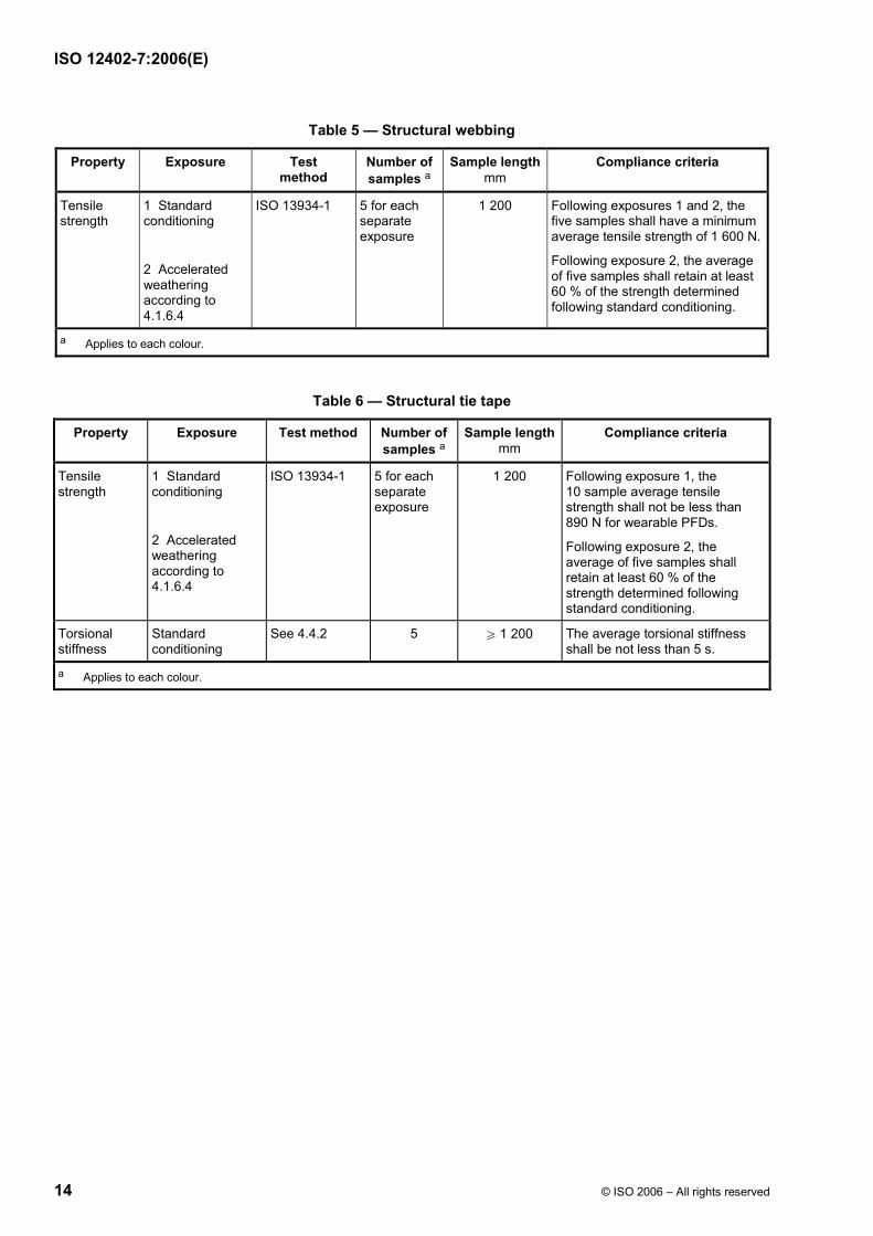
ISO 12402-7:2006(E)
14 © ISO 2006 – All rights reserved
Table 5 — Structural webbing
Property Exposure Test method
Number of samples a
Sample lengthmm
Compliance criteria
Tensile strength
1 Standard conditioning
2 Accelerated weathering according to 4.1.6.4
ISO 13934-1 5 for each separate exposure
1 200 Following exposures 1 and 2, the five samples shall have a minimum average tensile strength of 1 600 N.
Following exposure 2, the average of five samples shall retain at least 60 % of the strength determined following standard conditioning.
a Applies to each colour.
Table 6 — Structural tie tape
Property Exposure Test method Number of samples a
Sample lengthmm
Compliance criteria
Tensile strength
1 Standard conditioning
2 Accelerated weathering according to 4.1.6.4
ISO 13934-1 5 for each separate exposure
1 200 Following exposure 1, the 10 sample average tensile strength shall not be less than 890 N for wearable PFDs.
Following exposure 2, the average of five samples shall retain at least 60 % of the strength determined following standard conditioning.
Torsional stiffness
Standard conditioning
See 4.4.2 5 W 1 200 The average torsional stiffness shall be not less than 5 s.
a Applies to each colour.

ISO 12402-7:2006(E)
© ISO 2006 – All rights reserved 15
4.5 Structural lacing
4.5.1 Construction
Structural lacing shall be at least 3 mm in diameter or 6 mm in width.
4.5.2 Performance
Structural lacing shall comply with the acceptance criteria specified in Table 7 when subjected to the tests specified in this table.
Table 7 — Structural lacing
Property Exposure Test method
Number of samples a
Samplelength
mm
Compliance criteria
Tensile strength
1 Standard conditioning
2 Accelerated weathering according to 4.1.6.4
ISO 13934-1 5 for each separate exposure
1 200 Following exposure 1, the average tensile strength of five samples shall be at least 530 N.
Following exposure 2, the average tensile strength of five samples shall retain at least 60 % of the strength determined following standard conditioning.
a Applies to each colour.
4.6 Structural zippers
4.6.1 Construction
A zipper pull shall be at least 24 mm long. Projections (i.e. raised material) on the end of the zipper pull shall be provided to make the zipper pull easier to grasp.
When the pin is properly seated for closing the zipper, the retainer of a zipper shall engage with the separable pin and the slider shall engage the chain.
The slider of the zipper shall be of the automatic locking type.
4.6.2 Performance
4.6.2.1 General
Zippers shall comply with the acceptance criteria specified in Table 8 when subjected to the tests specified in this table.
4.6.2.2 Operability force test
For each set of six samples (see Table 8), three shall be used to determine the force required to open the zipper, and three shall be used to determine the force required to close the zipper. Samples for opening force shall be closed for conditioning. Samples for closing force shall be open (separated) for conditioning. Tests shall be conducted on the slider and on the moveable retainer, when provided.

ISO 12402-7:2006(E)
16 © ISO 2006 – All rights reserved
Table 8 — Zippers
Property Exposure Test method Number of samples a
Samplelength
mm
Compliance criteria
Operability force
1 Standard conditioning
2 70 h immersion in fuel B according to ASTM D 471-98 or diesel fuel according to EN 590 c
3 70 h immersion in
IRM 902 oil according to ASTM D 471-98
4 70 h immersion in 0,5 % detergent according to ISO 6330
5 720 h of salt spray according to 4.1.5.2 b
6 Accelerated weathering according to 4.1.6.4
ASTM D 2062 Six for each separate exposure
150 Following each separate exposure 1 to 6, the force exerted to open or close the zipper shall not exceed 65 N.
Additionally, the same samples shall comply with the applicable requirements in the crosswise strength test following this test.
Crosswise strength
1 Standard conditioning
2 70 h immersion in fuel B according to ASTM D 471-98 or diesel fuel according to EN 590 c
3 70 h immersion in IRM 902 oil according to ASTM D 471-98
4 70 h immersion in 0,5 % detergent according to ISO 6330
5 720 h of salt spray according to 4.1.5.2 b
6 Accelerated weathering according to 4.1.6.4
See 4.6.2.3 Samples used in the operability force tests
150 Following each separate exposure 1 to 6, the average strength shall be not less than:
a) 220 N for the top (including slider);
b) 220 N for the chain (crosswise);
c) 130 N for the separating unit (crosswise).
Following exposures 2 to 5, the average of six samples shall retain at least 60 % of the strength determined following standard conditioning.
Following exposure 6, the average of six samples shall retain at least 40 % of the strength determined following standard conditioning.
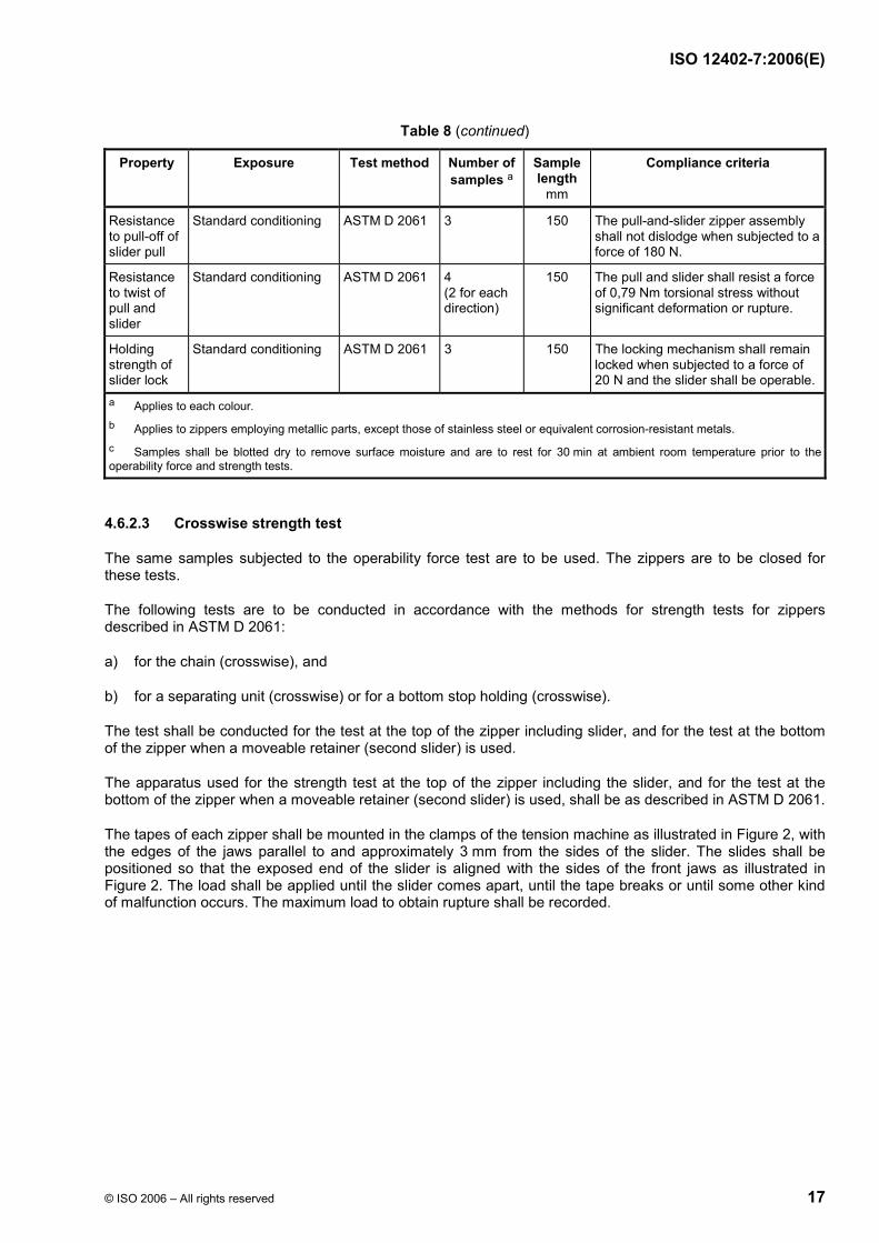
ISO 12402-7:2006(E)
© ISO 2006 – All rights reserved 17
Table 8 (continued)
Property Exposure Test method Number of samples a
Samplelength
mm
Compliance criteria
Resistance to pull-off of slider pull
Standard conditioning ASTM D 2061 3 150 The pull-and-slider zipper assembly shall not dislodge when subjected to a force of 180 N.
Resistance to twist of pull and slider
Standard conditioning ASTM D 2061 4 (2 for each direction)
150 The pull and slider shall resist a force of 0,79 Nm torsional stress without significant deformation or rupture.
Holding strength of slider lock
Standard conditioning ASTM D 2061 3 150 The locking mechanism shall remain locked when subjected to a force of 20 N and the slider shall be operable.
a Applies to each colour. b Applies to zippers employing metallic parts, except those of stainless steel or equivalent corrosion-resistant metals. c Samples shall be blotted dry to remove surface moisture and are to rest for 30 min at ambient room temperature prior to the operability force and strength tests.
4.6.2.3 Crosswise strength test
The same samples subjected to the operability force test are to be used. The zippers are to be closed for these tests.
The following tests are to be conducted in accordance with the methods for strength tests for zippers described in ASTM D 2061:
a) for the chain (crosswise), and
b) for a separating unit (crosswise) or for a bottom stop holding (crosswise).
The test shall be conducted for the test at the top of the zipper including slider, and for the test at the bottom of the zipper when a moveable retainer (second slider) is used.
The apparatus used for the strength test at the top of the zipper including the slider, and for the test at the bottom of the zipper when a moveable retainer (second slider) is used, shall be as described in ASTM D 2061.
The tapes of each zipper shall be mounted in the clamps of the tension machine as illustrated in Figure 2, with the edges of the jaws parallel to and approximately 3 mm from the sides of the slider. The slides shall be positioned so that the exposed end of the slider is aligned with the sides of the front jaws as illustrated in Figure 2. The load shall be applied until the slider comes apart, until the tape breaks or until some other kind of malfunction occurs. The maximum load to obtain rupture shall be recorded.
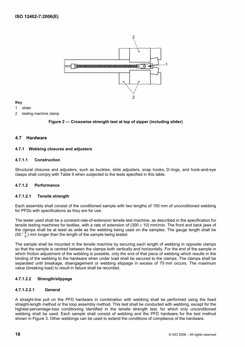
ISO 12402-7:2006(E)
18 © ISO 2006 – All rights reserved
Key 1 slider 2 testing machine clamp
Figure 2 — Crosswise strength test at top of zipper (including slider)
4.7 Hardware
4.7.1 Webbing closures and adjusters
4.7.1.1 Construction
Structural closures and adjusters, such as buckles, slide adjusters, snap hooks, D rings, and hook-and-eye clasps shall comply with Table 9 when subjected to the tests specified in this table.
4.7.1.2 Performance
4.7.1.2.1 Tensile strength
Each assembly shall consist of the conditioned sample with two lengths of 150 mm of unconditioned webbing for PFDs with specifications as they are for use.
The tester used shall be a constant-rate-of-extension tensile test machine, as described in the specification for tensile testing machines for textiles, with a rate of extension of (300 ± 10) mm/min. The front and back jaws of the clamps shall be at least as wide as the webbing being used on the samples. The gauge length shall be (50 5
0+ ) mm longer than the length of the sample being tested.
The sample shall be mounted in the tensile machine by securing each length of webbing in opposite clamps so that the sample is centred between the clamps both vertically and horizontally. For the end of the sample in which friction adjustment of the webbing is possible, only the end of that piece of webbing which results in the binding of the webbing to the hardware when under load shall be secured to the clamps. The clamps shall be separated until breakage, disengagement or webbing slippage in excess of 75 mm occurs. The maximum value (breaking load) to result in failure shall be recorded.
4.7.1.2.2 Strength/slippage
4.7.1.2.2.1 General
A straight-line pull on the PFD hardware in combination with webbing shall be performed using the fixed straight-length method or the loop assembly method. This test shall be conducted with webbing, except for the highest-percentage-loss conditioning identified in the tensile strength test, for which only unconditioned webbing shall be used. Each sample shall consist of webbing and the PFD hardware for the test method shown in Figure 3. Other webbings can be used to extend the conditions of compliance of the hardware.

ISO 12402-7:2006(E)
© ISO 2006 – All rights reserved 19
The lengths of webbing shall be connected to opposite sides of the hardware according to the routing method recommended by the hardware manufacturer. One length of the webbing shall be attached to a hoist and the other shall be attached to a weight according to Table 9.
A pre-load of (4,5 ± 0,9) kg shall be applied and the webbing shall be marked at the bottom of the adjustable end of the hardware to allow for measurement of slippage after the test. The remainder of the applicable load shall be applied for the required duration. The load shall then be removed and the webbing remarked at the bottom of the hardware. The distance between the marks shall be measured to the nearest 1,0 mm to determine the extent of slippage.
Table 9 — Webbing closures and adjusters
Property Exposure Test method Number of samples a, b
Compliance criteria
Tensile strength
1 Standard conditioning
2 70 h immersion in fuel B according to ASTM D 471-98 or diesel fuel according to EN 590 c
3 70 h immersion in IRM 902 oil according to ASTM D 471-98 c
4 70 h immersion in 0,5 % detergent according to ISO 6330
5 (70 ± 2) °C for 7 d c
6 (− 30 ± 2) °C for 24 h d
7 720 h of salt spray according to 4.1.5.2
8 Fatigue f
9 Accelerated weathering according to 4.1.6.4
See 4.7.1.2.1 5 for each separate condi- tioning
Following each separate exposure 1 to 9,
a) hardware shall have a minimum strength of 890 N; or
b) where hardware is intended for use in meeting the PFD horizontal load test requirement for lifejackets, or is a single load-bearing member intended for use in meeting the PFD horizontal load test requirement for buoyancy aids, hardware shall have a minimum tensile strength of 1 600 N.
For exposures 2 to 9, the average of five samples shall retain at least 60 % of the strength determined from standard conditioning.

ISO 12402-7:2006(E)
20 © ISO 2006 – All rights reserved
Table 9 (continued)
Property Exposure Test method Number of samples a, b
Compliance criteria
Strength/ slippage
1 Standard conditioning
2 2 min water soak f
3 The same exposure as tensile strength exposure that resulted in greatest percentage strength loss e
See 4.7.1.2.2 5 for each separate exposure
For exposures 1 to 3, each sample shall support without breaking, distorting, or slipping more than 25 mm load of
a) 890 N g;
b) 1 600 N g for 30 min where hardware is intended for use in meeting the PFD horizontal load test requirement for lifejackets, or is a single load-bearing member intended for use in meeting the PFD horizontal load test requirement for buoyancy aids.
Inadvertent release test (dual-tab closures only)
Standard conditioning See 4.7.1.2.3 5 Each sample shall support for 5 min without breaking, and without disengagement or similar condition, a load of at least 50 % of the minimum tensile strength specified for exposure 1 in the tensile strength test for the standard conditioning using webbing for PFDs.
a Applies to each colour. b For polymeric hardware, a minimum of 75 hardware/webbing samples. For metal hardware, 30 hardware/webbing samples. c Samples shall be blotted dry to remove surface moisture and are to rest for 30 min at ambient room temperature prior to the strength test. d Immediately following removal from the cold chamber, the samples shall be dropped using different orientations onto a concrete floor five times from a height of 1 800 mm. Each sample shall then be manually operated five times and then examined for signs of cracking. The samples shall then be returned to the cold chamber for 15 min. The samples shall then be individually removed and subjected to the tensile strength test and strength/slippage test. e Each flexible or moveable tab of polymeric part shall be mechanically operated for 5 000 cycles at a rate of 1 cycle per second. The tab shall be completely engaged/disengaged. Also, for hardware which is designed to separate into two parts (i.e. buckles), the parts shall be completely engaged/disengaged. In addition, the samples shall be manually operated five times prior to the tensile strength test and strength/slippage test. f The webbing which is used for the applicable tests in 4.7.1.2.1 shall be soaked in fresh water for 2 min prior to the strength/slippage test. g Strength values are for the fixed-straight-length body strap method. The values shall be doubled for the closed-loop assembly method.
4.7.1.2.2.2 Loop assembly method
For the loop assembly method, each assembly shall be closed to form a loop. Each assembly loop shall be supported vertically over a cylinder, with a second cylinder providing means for load application, illustrated in Figure 3. The body strap shall be marked at the sample to allow for measurement of the slippage after the test. Twice the applicable load specified for the fixed straight-length method shall be applied.
4.7.1.2.2.3 Fixed straight-length method
For the fixed straight-length method, connect a static load to one length of the body strap illustrated in Figure 3. For this test method, one length of the body strap shall be attached to a hoist and the other end to a weight. The body strap shall be marked at the sample to allow for measurement of the slippage after the test. The applicable load shall be applied through the bottom piece of the body strap.

ISO 12402-7:2006(E)
© ISO 2006 – All rights reserved 21
4.7.1.2.3 Inadvertent release test (dual-tab closure)
With one tab depressed, the samples shall comply with the compliance criteria specified in Table 9.
The webbing and test method shall be as described for the fixed straight-length body strap test method specified in 4.7.1.2.2, except that one tab shall be depressed. A pre-load of (2,3 ± 0,5) kg shall be applied to each closure so that when the release tab is depressed it does not slip back into the locked position. The remaining load shall then be applied.
a) Fixed straight-length method b) Loop assembly method
Key 1 600 mm length body strap rigged to hoist and hardware 2 600 mm length body strap rigged to weight No. 1 3 weight No. 1 (for fixed straight-length test) 4 weight No. 2 (for closed loop test, twice weight No. 1) 5 1 200 mm length body strap rigged to hardware 6 cylinder of 124 mm diameter
Figure 3 — Strength/slippage test methods
4.7.2 Lacing closures and adjusters
4.7.2.1 General
Structural closures and adjusters for lacing used in a primary or secondary closure or adjustment system shall comply with Table 10 when subjected to the tests specified in this table.
4.7.2.2 Performance
4.7.2.2.1 Tensile strength
Each assembly shall consist of the sample with two lengths of 150 mm of lacing attached as they are for use. For hardware that depends on friction for adjustment of the lacing, any adjustment tab shall be depressed with a force of 5 N to secure the lacing prior to testing.
ISO 12402-7:2006(E)
22 © ISO 2006 – All rights reserved
The tester shall be a constant-rate-of-extension tensile test machine as described in the specification for tensile testing machines for textiles, with a rate of extension of (300 ± 10) mm/min. The front and back jaws of the clamps shall be at least as wide as the lacing being used on the samples. The gauge length shall be (50 5
0+− ) mm longer than the width of the sample being tested.
The sample shall be mounted in the tensile machine by securing each length of lacing in opposite clamps so that the lacing grip area of the sample is centred between the clamps both vertically and horizontally. Only the ends of the lacing which result in the binding of the lacing to the hardware when under load shall be secured to the clamps. The clamps shall be separated until breakage, disengagement, lacing slippage in excess of 75 mm or a similar condition occurs. The maximum value (breaking load) to cause failure shall be recorded.
4.7.2.2.2 Strength/slippage
4.7.2.2.2.1 General
Each assembly shall consist of the sample with 1 200 mm of lacing attached as for use. For hardware that depends on friction for adjustment of the lacing, any adjustment tab shall be depressed with a force of 5 N to secure the lacing prior to testing. Also, it shall be possible to conduct this test in accordance with either the fixed straight-length method or the loop assembly method. This test shall be conducted with each lacing for which the hardware is intended.
4.7.2.2.2.2 Loop assembly method
For the loop assembly method, each assembly shall be closed to form a loop. Each assembly loop shall be supported vertically over a cylinder, with a second cylinder providing the means for load application, similar to the method illustrated in Figure 3. The lacing shall be marked at the sample to allow for measurement of the slippage after the test. Twice the applicable load specified in Table 10 shall be applied.
4.7.2.2.2.3 Fixed straight-length method
For the fixed straight-length method, connect a static load to fixed straight 600 mm lengths of lacing on each side of the sample, similar to the method illustrated in Figure 3. For this test method, one length of the lacing shall be attached to a hoist and the other end shall be attached to a weight in accordance with Table 10. The lacing shall be marked at the sample to allow for measurement of the slippage after the test. The applicable load specified in Table 10 shall be applied through the bottom piece of lacing.
4.7.2.2.3 Tab disengagement test
Each assembly shall consist of the sample with two lengths of 600 mm of lacing attached as they are for use. For hardware that depends on friction for adjustment of the lacing, any adjustment tab shall be depressed with a force of 5 N to secure the lacing prior to testing.
One of the lacing ends that results in the binding of the lacing to the hardware shall be secured in a rigid fixture. The other lacing end that results in the binding of the lacing to the hardware shall be attached to a 2,25 kg deadweight. The deadweight shall be suspended from the lacing and then raised 300 mm from the suspended position. The deadweight shall then be released so a shock load is applied to the sample.
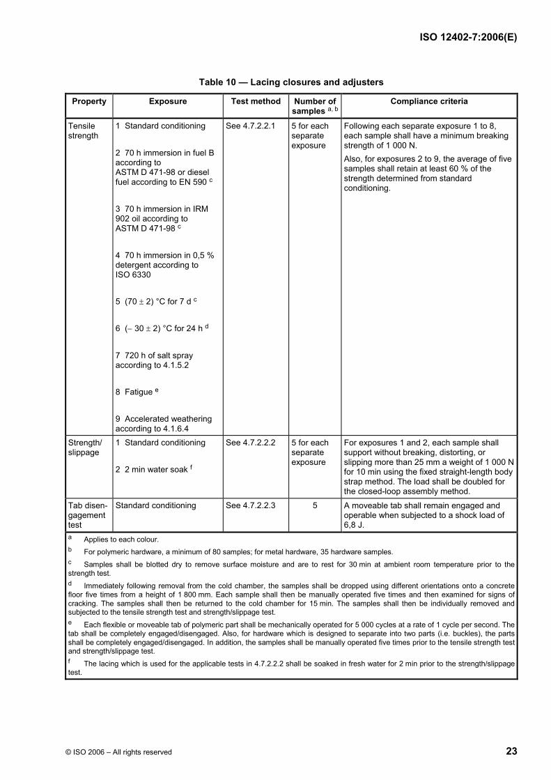
ISO 12402-7:2006(E)
© ISO 2006 – All rights reserved 23
Table 10 — Lacing closures and adjusters
Property Exposure Test method Number of samples a, b
Compliance criteria
Tensile strength
1 Standard conditioning 2 70 h immersion in fuel B according to ASTM D 471-98 or diesel fuel according to EN 590 c 3 70 h immersion in IRM 902 oil according to ASTM D 471-98 c 4 70 h immersion in 0,5 % detergent according to ISO 6330 5 (70 ± 2) °C for 7 d c 6 (− 30 ± 2) °C for 24 h d
7 720 h of salt spray according to 4.1.5.2 8 Fatigue e 9 Accelerated weathering according to 4.1.6.4
See 4.7.2.2.1 5 for each separate exposure
Following each separate exposure 1 to 8, each sample shall have a minimum breaking strength of 1 000 N. Also, for exposures 2 to 9, the average of five samples shall retain at least 60 % of the strength determined from standard conditioning.
Strength/ slippage
1 Standard conditioning 2 2 min water soak f
See 4.7.2.2.2 5 for each separate exposure
For exposures 1 and 2, each sample shall support without breaking, distorting, or slipping more than 25 mm a weight of 1 000 N for 10 min using the fixed straight-length body strap method. The load shall be doubled for the closed-loop assembly method.
Tab disen-gagement test
Standard conditioning See 4.7.2.2.3 5 A moveable tab shall remain engaged and operable when subjected to a shock load of 6,8 J.
a Applies to each colour. b For polymeric hardware, a minimum of 80 samples; for metal hardware, 35 hardware samples. c Samples shall be blotted dry to remove surface moisture and are to rest for 30 min at ambient room temperature prior to the strength test. d Immediately following removal from the cold chamber, the samples shall be dropped using different orientations onto a concrete floor five times from a height of 1 800 mm. Each sample shall then be manually operated five times and then examined for signs of cracking. The samples shall then be returned to the cold chamber for 15 min. The samples shall then be individually removed and subjected to the tensile strength test and strength/slippage test. e Each flexible or moveable tab of polymeric part shall be mechanically operated for 5 000 cycles at a rate of 1 cycle per second. The tab shall be completely engaged/disengaged. Also, for hardware which is designed to separate into two parts (i.e. buckles), the parts shall be completely engaged/disengaged. In addition, the samples shall be manually operated five times prior to the tensile strength test and strength/slippage test. f The lacing which is used for the applicable tests in 4.7.2.2.2 shall be soaked in fresh water for 2 min prior to the strength/slippage test.

ISO 12402-7:2006(E)
24 © ISO 2006 – All rights reserved
4.7.3 Multi-eyelet guides
4.7.3.1 Construction
A multi-eyelet guide for use with lacing shall comply with the compliance criteria specified in Table 11 when subjected to the tests specified in this table.
4.7.3.2 Performance
4.7.3.2.1 Tensile strength
Each sample shall be cut into test specimens 25 mm wide with one lacing loop centred. Each sample shall be independently mounted in a constant-rate-of-traverse tension machine. The flat side of the sample shall be clamped in one jaw and lacing shall be passed through the loop of the sample. Each end of the lacing shall be clamped in the other jaw of the tension machine. The initial jaw separation shall be 100 mm to 150 mm. The jaws shall be separated at a rate of 75 mm/min and the load in newtons at rupture shall be recorded.
4.7.3.2.2 Cold flexibility test
Immediately upon removal from the cold chamber, each sample specimen shall independently be bent both lengthways and widthways around a 25 mm mandrel until each end touches. The mandrel shall be in the cold chamber with the samples during the exposure.
Table 11 — Multi-eyelet guides
Property Exposure Test method Number of samples a
Compliance criteria
Tensile strength See Table 10 See 4.7.3.2.1 5 for each exposure
The average breaking strength shall not be less than 450 N.
Cold flexibility (−30 ±2) °C for 24 h See 4.7.3.2.2 5 Each sample shall not break or be permanently distorted.
a Applies to each colour.
4.8 Foam flotation material
4.8.1 General
The properties of foam flotation material shall be investigated in accordance with Table 12 and 4.8.2 and shall comply with the compliance criteria specified therein.
Except where otherwise noted, samples of foam flotation material shall measure at least 300 mm by 300 mm by the thickness of the material being investigated. When a material is 16 mm thick or less, the material shall be stacked to the number of layers that provides samples closest to 25 mm in thickness. The condition of the material shall be representative of that intended for the end-product (for example, with or without skin).
For the purposes of these requirements, skin is a dense outer layer of the foam flotation material. Tests shall be provided in three batches consisting of six samples per batch.

ISO 12402-7:2006(E)
© ISO 2006 – All rights reserved 25
Table 12 — Foam flotation material
Property Test method Number of samples Compliance criteria a
Density See 4.8.2.1 18 b Baseline test.
Specific buoyancy See 4.8.2.2 18 Baseline test.
Compression d See 4.8.2.4 or 4.8.2.5 h
18 c The maximum loss of buoyancy for the average of all samples shall not exceed 10 %.
Thermal stability d See 4.8.2.3 or 4.8.2.5 h
3 d The maximum loss of volume in any sample shall not exceed 5 % and there shall be no sign of damage such as shrinking, cracking, swelling, dissolution or change of mechanical qualities, when compared with unconditioned specimens.h
Buoyancy retention factors, alternative to compression and thermal stability: d, h V-factor (for wearable devices)
4.8.2.5 9 c, e 94 V for material used to make up at least 85 % of the required buoyancy in a PFD meeting ISO 12402-1 to ISO 12402-3.
85 V for material used to make up at least 85 % of the required buoyancy in a PFD meeting ISO 12402-4 to ISO 12402-6.
80 V for material making up no more than 15 % of the required buoyancy in any PFD.
Tensile strength See 4.8.2.6 5 f The average tensile strength shall be not less than 140 kPa for foam which is a structural part of the device, i.e. not retained by a cover fabric.
Oil resistance See 4.8.2.7 3 e There shall be no visible volume change, softening, nor deterioration of a material when compared with unconditioned specimens, and the average tensile strength of the material shall be not less than 75 % of the value determined for the unconditioned specimens.
Cold flexibility See 4.8.2.8 3 e There shall be no cracking when examined under a magnification of 5 ×.
Compression deflection See 4.8.2.9 3 f The force required to deflect the material to 75 % of its original thickness shall be at least 7 kPa.
Dimensional analysis See 4.8.2.10 1 Baseline test.
Thickness See 4.8.2.11 4 g The average thickness shall be within ± 10 % of the design values.
a The use of foam buoyant material is dependent on (and not limited to) the thickness, buoyancy retention factor, the type of PFD for which it is intended, and how it is enclosed in the PFD. b Six samples shall be taken from each of three lots of foam flotation material. c The samples shall be the same samples used in the specific buoyancy measurements. d This property shall be investigated for each nominal thickness in which the foam flotation material is produced; except that for material produced in thicknesses greater than 25 mm, a plot of property values versus thickness based upon at least three thicknesses (thinnest, midrange, and thickest) of 25 mm and greater is used to obtain values for intermediate thickness. e Samples from one or more lots. f One sample from each lot. g Two samples from batch 1 and one sample each from batches 2 and 3. h When the alternative tests in 4.8.2.5 are used, the resulting retention factors shall be used to compensate for the projected loss of buoyancy as specified in 5.3.4.2 of ISO 12402-1:— 2) to ISO 12402-6:— 2).
2) To be published.

ISO 12402-7:2006(E)
26 © ISO 2006 – All rights reserved
4.8.2 Performance
4.8.2.1 Density after water absorption
The mass of each individual sample shall be determined by using an analytical balance with an accuracy of ± 0,5 g. The samples shall then be immersed to a depth of 50 mm in fresh water at room temperature for 24 h. The initial volume of each sample shall be determined immediately after the water soak specified by
a) measuring and recording the initial water level, Wi, in an inclined manometer tube to the nearest millimetre;
b) submerging the foam in a rigid container (that is connected to the manometer) filled with fresh water; and
c) measuring and recording the final water level, Wf, to the nearest millimetre.
The volume, V, of the foam flotation material shall then be calculated by multiplying the difference between the water levels Wf and Wi by the cross-sectional area, A, of the rigid container:
( )f iV W W A= − × (2)
where
V is the volume of an individual sample, in cubic millimetres;
Wf is the final water level of manometer container, in millimetres;
Wi is the initial water level of manometer container, in millimetres;
A is the horizontal cross-sectional area of the container (i.e., L × W), in square millimetres.
The density (D) shall then be determined by the following equation:
mDV
= (3)
where
D is the density of an individual sample, in kilograms per cubic metre;
m is the mass of an individual sample, in kilograms;
V is the volume of an individual sample, in cubic metres.

ISO 12402-7:2006(E)
© ISO 2006 – All rights reserved 27
4.8.2.2 Specific buoyancy
The corrected initial buoyancy of each sample shall be determined, after 24 h of water immersion to a depth of 50 mm of fresh water at room temperature by
a) weighing the sample to the nearest gram while completely submerged underwater;
b) reading the individual buoyancy to the nearest gram directly from the digital readout; and
c) correcting the results to an atmospheric pressure of 760 mm Hg and a water temperature of 20 °C as follows:
ICI I
I
293,15 K101,3 273,15
PB B
T= × ×
+ (4)
where
BCI is the corrected initial buoyancy, in newtons;
BI is the initial measured buoyancy, in newtons;
PI is the initial atmospheric pressure, in kilopascals;
TI is the initial temperature, in degrees Celsius;
The initial specific buoyancy value of each sample shall be individually computed in accordance with the following formula:
CI1
BSB
V= (5)
where
SB1 is the initial specific buoyancy, in newtons per cubic millimetre;
BCI is the corrected initial buoyancy, in newtons, determined in accordance with formula (5);
V is the volume of an individual sample, in cubic millimetres, determined in accordance with 4.8.2.1.
4.8.2.3 Thermal stability of buoyancy material
Three test specimens of dimensions (200 ± 2) mm × (200 ± 2) mm and of thickness (20 ± 2) mm shall be conditioned initially in air at (23 ± 2) °C and (50 ± 5) % relative humidity for at least 24 h before carrying out the test. If the buoyancy material is of a granular form, or consists of sheets thinner than 20 mm, then either a number of layers shall be used to achieve a minimum total thickness of 20 mm, or a minimum volume of material of 100 cm3 shall be tested, as appropriate.
Each specimen shall then be weighed in air, and undergo measurements to determine its volume. If the volume is measured by displacement of water, the specimens shall be conditioned in air at (23 ± 2) °C and a relative humidity of (50 ± 5) % for (24,0 ± 0,5) h.
They shall then be placed on a flat surface in an oven maintained at an even temperature of (65 ± 1) °C with air circulating at the rate of 3 to 10 changes per hour, for a period of (8,0 ± 0,5) h. Only test specimens from the same type material shall be conditioned in one oven at the same time.
ISO 12402-7:2006(E)
28 © ISO 2006 – All rights reserved
Following removal from the oven, specimens shall be laid on a flat surface for (16,0 ± 0,5) h at (23 ± 2) °C and (50 ± 5) % relative humidity.
They shall then be exposed in a similar container to an even temperature of (− 30 ± 1) °C for a period of (8,0 ± 0,5) h, then removed and laid on the flat surface for (16,0 ± 0,5) h at room temperature as before.
This cycle of exposure to alternating high and low temperatures shall be repeated until the samples have been exposed to each temperature for ten periods. The measurements shall then be repeated, and the percentage volume change calculated.
4.8.2.4 Test method for the compressibility of inherently buoyant material
4.8.2.4.1 Calculation
Examine three specimens of each sample of foam of dimensions (100 ± 2) mm × (100 ± 2) mm and of thickness (20 ± 2) mm. Prior to the test, they shall have been stored at (23 ± 2) °C and a relative humidity of (50 ± 5) % for 24 h, and they shall be tested under these conditions. The initial buoyancy shall be determined in newtons for each of the three specimens and an average initial buoyancy shall be calculated as follows:
1I 2 I 3 II 3
B B BB
+ += (6)
where
BI is the average initial buoyancy, in newtons;
B1 I is the initial measured buoyancy of sample 1, in newtons;
B2 I is the initial measured buoyancy of sample 2, in newtons;
B3 I is the initial measured buoyancy of sample 3, in newtons.
The corrected initial buoyancy in newtons shall then be calculated as follows:
ICI I
I
293,15 K101,3 273,15
PB B
T= × ×
+ (7)
where
BCI is the corrected initial buoyancy, in newtons;
BI is the initial measured buoyancy, in newtons;
PI is the initial atmospheric pressure, in kilopascals;
TI is the initial temperature, in degrees Celsius;
4.8.2.4.2 Procedure
4.8.2.4.2.1 Each specimen shall be placed in fresh water under a flat metal plate at least 20 % larger than the specimen size and then compressed at a speed of 200 mm/min until a pressure of 50 kPa has been reached. This lower position shall be set for further compressions. The specimen shall then be completely decompressed, and the cycle of compression repeated a further four times, using the lower set point as the limit of compression.
ISO 12402-7:2006(E)
© ISO 2006 – All rights reserved 29
4.8.2.4.2.2 The specimen shall then be dried for 7 d in air at a temperature of (23 ± 2) °C and a relative humidity of (50 ± 5) %. The compression cycles shall then be repeated without water and for a total of 500 times. If deformation occurs, then the upper set point might need to be reset in order to keep the decompression/compression time equal during the whole test period.
4.8.2.4.2.3 The specimen shall then be returned to the atmosphere in 4.8.2.4.2.2 for at least 3 d, and the final buoyancy value shall be determined according to 4.8.2.2 for each of the three specimens in newtons, and an average final buoyancy value shall be calculated as follows:
1F 2 F 3 FF 3
B B BB
+ += (8)
where
B1 F is the final measured buoyancy of sample 1, in newtons;
B2 F is the final measured buoyancy of sample 2, in newtons;
B3 F is the final measured buoyancy of sample 3, in newtons.
A corrected final buoyancy in newtons shall then be calculated as follows:
FCF F
F
293,15 K101,3 273,15
PB B
T= × ×
+ (9)
where
BCF is the corrected final buoyancy, in newtons;
BF is the final measured buoyancy, in newtons;
PF is the final atmospheric pressure, in kilopascals;
TF is the final temperature, in degrees Celsius;
The loss of buoyancy, BL,shall then be expressed as a percentage of the corrected initial buoyancy as follows:
CI CFL
CI100
B BB
B−
= × (10)
The loss of buoyancy shall not exceed 10 % of the originally measured buoyancy value.
4.8.2.5 Buoyancy retention factor
4.8.2.5.1 General
When this test procedure is used, the resulting retention factors shall be used to compensate for the projected loss of buoyancy as specified in ISO 12402-1 to ISO 12402-6.
4.8.2.5.2 Conditioning
The samples shall be subjected to the following sequential conditioning.
a) Initial storage. The samples shall be individually stored on racks for (120 ± 1) h at (23 ± 2) °C.
b) Initial immersion. The samples shall be immersed in fresh water at room temperature for (24 ± 0,5) h with their top surface at a depth of (50 ± 5) mm, followed by measurement of the initial buoyancy of each sample by determining, to the nearest 0,01 N, the force needed to keep the sample at this depth.

ISO 12402-7:2006(E)
30 © ISO 2006 – All rights reserved
c) Heat conditioning. The samples shall be conditioned for 120 h in an air-circulating oven at a temperature of (60 ± 2) °C. A spacing of at least 25 mm shall be maintained between the samples.
d) Cool-down. Immediately after removal from the oven, the samples shall be immersed to a depth of (50 ± 5) mm in fresh water at a temperature of (23 ± 2) °C for (15 ± 1) min.
e) V-factor compression. Immediately after removal from the water, the samples shall be subjected to a load of (120 ± 6) kg as described in f).
f) Compression application. Each individual sample shall be placed on top of a flat, rigid surface that extends at least 25 mm beyond the sample on all sides. The specified load for V-factor testing [see e)] shall be uniformly applied to the top of the sample for (24 ± 0,5) h. The ambient temperature shall be (23 ± 2) °C during the compression application.
NOTE Provided that each individual sample is placed between two flat, rigid surfaces that extend at least 25 mm beyond the sample on all sides, this loading arrangement may be achieved by stacking up to nine layers with the load applied to the top of the stack.
g) Recovery storage. All the samples shall be stored on racks at (23 ± 2) °C for (264 ± 1) h. A spacing of at least 25 mm is to be maintained between the samples.
h) Final immersion. The samples shall then be completely submerged in fresh water at room temperature for (24 ± 1) h with their top surface at a depth of (50 ± 5) mm, followed by measurement of the final buoyancy (Bf) of each sample by determining, to the nearest 0,01 N, the force needed to keep the sample at this depth.
4.8.2.5.3 Calculations
The V-factor for the foam flotation material, as determined from the buoyancy of individual samples subjected to the conditioning and 120-kg compression specified in 4.8.2.5.2, shall be calculated using the following equation and rounding off the value obtained to the nearest whole number:
V-factor = f1 i
100 Ni
BN B=∑ (11)
where
Bf is the final buoyancy of an individual sample, as determined in accordance with 4.8.2.5.2 h);
Bi is the initial buoyancy of an individual sample, as determined in accordance with 4.8.2.5.2 b);
N is the number of samples subjected to the compression.
The V-factor assigned to a given thickness of a unique formulation of foam flotation material shall be either the value calculated in accordance with equation (11) or the lowest V-factor calculated for all greater thicknesses of the same formulation, whichever is lower.
4.8.2.6 Tensile strength
Prior to the tensile strength test, the dumbbell-shaped specimens shall be conditioned under standard conditions.
Dumbbell-shaped specimens shall be cut from the samples using Die A as specified in the standard test methods for rubber properties in tension specified in ISO 1926. Specimens from five of the samples shall be cut parallel to each other, and specimens from the other five samples shall be cut parallel to each other and in the direction perpendicular to that in which the specimens from the first five samples were cut. The top and bottom surfaces of the specimens shall be parallel, and the cut surfaces are to be perpendicular to the top surface and free from sharp or ragged edges. If skin is not a condition of acceptance, any surface skin or irregularities that affect the test results shall be removed by light buffing. When the material is more than 10 mm thick, the samples shall be prepared to a thickness of 10 mm or less.

ISO 12402-7:2006(E)
© ISO 2006 – All rights reserved 31
The cross-sectional area of the dumbbell-shaped specimens shall be calculated as follows:
A T W= × (12)
where
A is the cross-sectional area of the specimen, in square millimetres;
T is the average of three thickness measurements taken on the narrow section of the cut specimen, in millimetres;
W is the width of the specimen at the narrow section, in millimetres.
The tensile strength test for the dumbbell-shaped specimens shall be conducted as follows.
Each dumbbell-shaped specimen shall be individually clamped in the jaws of a tension machine and separated at a rate of 50 mm/min. The value at the time of rupture shall be recorded. After the tensile strength test, the average tensile strength of the samples shall comply with the compliance criteria specified in Table 12.
The tensile strength, F, for the dumbbell-shaped specimens is calculated as follows:
LFA
= (13)
where
L is the load required to rupture the sample, in newtons;
A is the cross-sectional area of the specimen, in square millimetres.
4.8.2.7 Oil resistance
Specimens shall be prepared as specified in 4.8.2.6.
The dumbbell-shaped specimens shall be completely immersed for 70 h in ASTM Reference Oil No. 2 at (23 ± 2) °C. Upon removal, the specimens shall be blotted with filter paper and compared with unconditioned specimens of the same dimensions for evidence of volume change, softening, or deterioration. The specimens shall stand for 30 min at (23 ± 2) °C. The specimens shall then be subjected to the tensile strength test specified in 4.8.2.6. Following this oil resistance and tensile strength test, the specimens shall comply with the compliance criteria specified in Table 12.
4.8.2.8 Cold flexibility
Samples shall be 25 mm × 200 mm by the thickness of the foam flotation material being investigated.
Prior to the test, the samples shall be conditioned for 4 h in air at (− 18 ± 1) °C. While at the same temperature, the longest dimension of the sample shall be wrapped 180° around a steel mandrel within 5 s of removal from the freezer. The mandrel shall have a diameter equal to two times the thickness of the foam flotation material under investigation.
Following this flexibility test, the specimens shall comply with the compliance criteria specified in Table 12.
4.8.2.9 Compression deflection
Each sample shall be compressed to 75 % of its original thickness. The pressure required to compress the sample to this thickness shall be recorded in kilopascals.

ISO 12402-7:2006(E)
32 © ISO 2006 – All rights reserved
A compression machine capable of gently compressing, without impact, each sample at a rate of 10 mm/min to 50 mm/min shall be used. The thickness of each sample shall be determined using a dial micrometer accurate to 0,01 mm. The compression machine shall utilize a square foot that is at least (110 × 110) mm in size.
Each sample shall be square, measuring (100 ± 3) mm × (100 ± 3) mm. Place the specimen centred in the line of the axial load on the supporting plate of the apparatus. Bring the compression foot into contact with the specimen and determine the thickness when pressure is detected. Compress the specimen by (25 ± 0,5) % of this thickness at the specified rate and take the reading of the load immediately. Calculate the 25 % compression deflection pressure, expressed as follows:
CDFPA
= (14)
where
PCD is the compression deflection pressure, in kilopascals;
F is the force required to compress the specimen by 25 % of the thickness, in kilonewtons;
A is the specimen compression contact surface area, in square metres.
Following this compression deflection test, the specimens shall comply with the compliance criteria specified in Table 12.
4.8.2.10 Dimensional analysis
A cross-sectional analysis of the foam flotation material shall be made by lightly highlighting a randomly selected area on the surface of the foam, 25 mm on each side, with a permanent marking pen. This area shall be examined for the ten cells identified as the largest, in terms of their maximum diameter, using an optical comparator.
4.8.2.11 Thickness
A dial-indicator measuring instrument with a circular presser foot area of 625 mm2 which exerts a pressure of 28 g shall be used for measuring the thickness of the samples. The indicator shall have a measuring accuracy of ± 0,1 mm. Five thickness measurements shall be made on each sample, and the average shall be computed for each sample. The average of the four samples shall then be calculated.
Following this thickness examination, the specimens shall comply with the compliance criteria specified in Table 12.
4.8.3 Knitted fabric laminated to foam flotation material
Structural-fabric-laminated foam flotation material, either one sided or two sided, shall comply with the compliance criteria specified in Table 15 or 16 as applicable, when subjected to the tests therein.
The foam provided with fabric-laminated foam flotation material, if required as part of a device’s buoyancy, shall comply with the requirements for foam flotation material, except that the material shall be tested in the thickness provided, not stacked to 25 mm.
4.9 Inflation chamber materials
4.9.1 General
Woven compartment materials for hybrid and fully inflatable PFDs shall comply with the compliance criteria specified in Table 13 when subjected to the tests therein.
The samples shall not include selvage and shall not be subject to more than one exposure.
If the material is susceptible to fungal attack, a relevant test can be carried out as described in Annex A.

ISO 12402-7:2006(E)
© ISO 2006 – All rights reserved 33
4.9.2 Performance
4.9.2.1 Tensile strength test
Each sample specified in Table 13 shall be tested as specified.
The dimension of the front jaws for each clamp shall be 25 mm × 25 mm and shall be rubber padded to prevent slippage. The dimension of the back jaw for each clamp shall be 25 mm parallel to the application of load by 25 mm or more perpendicular to the application of load. The initial jaw separation shall be 75 mm unless specified otherwise. The tensile testing machine shall be operated at a uniform pulling speed of (300 ± 10) mm/min. The load cell range shall be capable of providing the maximum load to break (break strength value shall be within 5 % to 95 % of full range). The samples shall be placed in the tensile testing machine with the long dimension parallel to the application of load. The samples shall be marked with a line 35 mm from the left edge that extends throughout the sample following along a single yarn. The sample shall be placed in the tensile testing machine with the marked line along the left edge of the upper and lower jaws to provide for equal yarn extension. The sample shall extend 10 mm above the top jaw and 10 mm below the bottom jaw.
4.9.2.2 Trapezoid tear strength test
Two samples, measuring 75 mm wide by 150 mm long shall be used. The warp samples shall be cut with the long dimension perpendicular to the warp yarns and the filling samples shall be cut with the long dimension parallel to the warp yarns. No two warp samples shall contain the same warp yarns and no two samples shall contain the same filling yarns. No sample shall include selvage.
An isosceles trapezoid having an altitude of 75 mm and bases of 25 mm and 100 mm shall be marked on each sample. A cut approximately 10 mm in length shall be made in the centre of and perpendicular to the 25 mm base. The specimen shall be clamped in the tensile testing machine along the nonparallel sides of the trapezoid so that these sides lie along the lower edge of the upper clamp and the upper edge of the lower clamp with the cut halfway between the clamps. The short trapezoid base shall be held taut and the long trapezoid base shall lie in the folds. Set the nominal gauge length at 25 mm and select the capacity of the tester suitable for the specimens to be tested. The maximum load required to tear the specimen shall be within the rated operating capacity of the tester. For a CRT machine, this should be considered as the range of 15 % to 85 % of the rated capacity.
Operate the pulling jaw at (300 ± 10) mm/min.
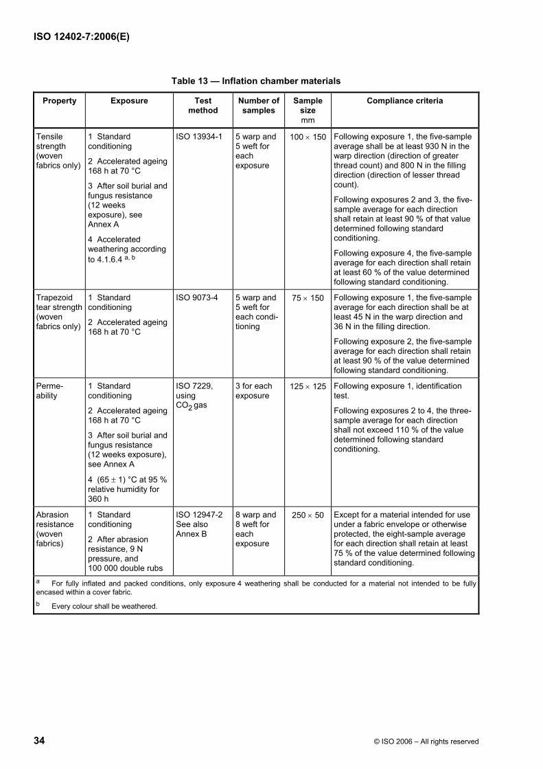
ISO 12402-7:2006(E)
34 © ISO 2006 – All rights reserved
Table 13 — Inflation chamber materials
Property Exposure Test method
Number of samples
Sample size mm
Compliance criteria
Tensile strength (woven fabrics only)
1 Standard conditioning
2 Accelerated ageing 168 h at 70 °C
3 After soil burial and fungus resistance (12 weeks exposure), see Annex A
4 Accelerated weathering according to 4.1.6.4 a, b
ISO 13934-1 5 warp and 5 weft for each exposure
100 × 150 Following exposure 1, the five-sample average shall be at least 930 N in the warp direction (direction of greater thread count) and 800 N in the filling direction (direction of lesser thread count).
Following exposures 2 and 3, the five-sample average for each direction shall retain at least 90 % of that value determined following standard conditioning.
Following exposure 4, the five-sample average for each direction shall retain at least 60 % of the value determined following standard conditioning.
Trapezoid tear strength (woven fabrics only)
1 Standard conditioning
2 Accelerated ageing 168 h at 70 °C
ISO 9073-4 5 warp and 5 weft for each condi-tioning
75 × 150 Following exposure 1, the five-sample average for each direction shall be at least 45 N in the warp direction and 36 N in the filling direction.
Following exposure 2, the five-sample average for each direction shall retain at least 90 % of the value determined following standard conditioning.
Perme-ability
1 Standard conditioning
2 Accelerated ageing 168 h at 70 °C
3 After soil burial and fungus resistance (12 weeks exposure), see Annex A
4 (65 ± 1) °C at 95 % relative humidity for 360 h
ISO 7229, using CO2 gas
3 for each exposure
125 × 125 Following exposure 1, identification test.
Following exposures 2 to 4, the three-sample average for each direction shall not exceed 110 % of the value determined following standard conditioning.
Abrasion resistance (woven fabrics)
1 Standard conditioning
2 After abrasion resistance, 9 N pressure, and 100 000 double rubs
ISO 12947-2 See also Annex B
8 warp and 8 weft for each exposure
250 × 50 Except for a material intended for use under a fabric envelope or otherwise protected, the eight-sample average for each direction shall retain at least 75 % of the value determined following standard conditioning.
a For fully inflated and packed conditions, only exposure 4 weathering shall be conducted for a material not intended to be fully encased within a cover fabric. b Every colour shall be weathered.
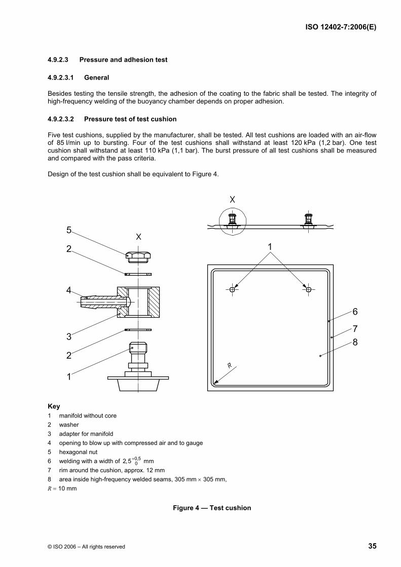
ISO 12402-7:2006(E)
© ISO 2006 – All rights reserved 35
4.9.2.3 Pressure and adhesion test
4.9.2.3.1 General
Besides testing the tensile strength, the adhesion of the coating to the fabric shall be tested. The integrity of high-frequency welding of the buoyancy chamber depends on proper adhesion.
4.9.2.3.2 Pressure test of test cushion
Five test cushions, supplied by the manufacturer, shall be tested. All test cushions are loaded with an air-flow of 85 l/min up to bursting. Four of the test cushions shall withstand at least 120 kPa (1,2 bar). One test cushion shall withstand at least 110 kPa (1,1 bar). The burst pressure of all test cushions shall be measured and compared with the pass criteria.
Design of the test cushion shall be equivalent to Figure 4.
Key 1 manifold without core 2 washer 3 adapter for manifold 4 opening to blow up with compressed air and to gauge 5 hexagonal nut 6 welding with a width of 0,5
02,5 mm+ 7 rim around the cushion, approx. 12 mm 8 area inside high-frequency welded seams, 305 mm × 305 mm, R = 10 mm
Figure 4 — Test cushion

ISO 12402-7:2006(E)
36 © ISO 2006 – All rights reserved
4.9.2.3.3 Cycling test of test cushion
Three test cushions, supplied by the manufacturer, shall be tested. The inside pressure shall change between a minimum pressure pmin = 10 kPa (100 mbar) and a maximum pressure pmax = 30 kPa (300 mbar) for 5 000 cycles. The air-flow shall be (85 ± 5) l/min. After these cycles, a test according to 4.9.2.3.2 shall be executed. Two test cushions shall withstand a burst pressure of at least 120 kPa (1,2 bar). One test cushion shall withstand at least 110 kPa (1,1 bar).
4.10 Polymeric foam coatings
4.10.1 Construction
Polymeric foam coatings shall comply with the following compliance criteria as specified in Table 14 when subjected to the tests therein.
Except for samples used for the adhesion to foam tests, the tests shall be conducted on samples of the coating that have been prepared, by the specified method, in the form of unsupported film in the minimum thickness specified.
The test piece shall be folded at its centre line, with the external sides laid together, and stored for 30 min in a heating chamber at a temperature of (82 ± 2) °C under a load of 50 N per 50 cm2. After removal from the heating chamber the sample shall be left to cool down for 2 h under standard atmosphere, then unfolded and examined for blocking or surface damage.
For evaluation the following criteria shall be used.
4.10.2 Performance
4.10.2.1 Coating adhesion
Coating adhesion shall be tested in accordance with ISO 2411, at 100 mm/min, and shall be not less than 7 N/cm. It shall also be tested when wet, following ageing according to ISO 188. An exposure of (336,0 ± 0,5) h in fresh water at (70,0 ± 1,0) °C, in accordance with ISO 2411:2000, shall be applied at 100 mm/min, and shall not be less than 7 N/cm.
4.10.2.2 Resistance to flex cracking
Resistance to flex cracking shall be tested in accordance with ISO 7854:1995, Method A using 9 000 flex cycles, following which there shall be no visible cracking or deterioration.
4.10.2.3 Elongation at break
Elongation at break shall be tested in accordance with ISO 1421:1998 using the CRE or CRT methods following conditioning of (24,0 ± 0,5) h immersion in fresh water at room temperature, and shall be not more than 60 %.
4.10.2.4 Cold flexibility
Within 5 s after removal from the cold chamber, each sample, in turn, shall be bent 180 ° around a 10-mm-diameter steel mandrel that has been conditioned with the samples.
4.10.2.5 Blocking
Resistance to blocking shall be investigated as follows.
⎯ Laminated foam flotation material having knitted fabric on both sides shall be tested as specified in Table 15 and shall comply with the compliance criteria therein.
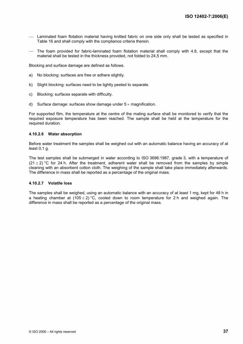
ISO 12402-7:2006(E)
© ISO 2006 – All rights reserved 37
⎯ Laminated foam flotation material having knitted fabric on one side only shall be tested as specified in Table 16 and shall comply with the compliance criteria therein.
⎯ The foam provided for fabric-laminated foam flotation material shall comply with 4.8, except that the material shall be tested in the thickness provided, not folded to 24,5 mm.
Blocking and surface damage are defined as follows.
a) No blocking: surfaces are free or adhere slightly.
b) Slight blocking: surfaces need to be lightly peeled to separate.
c) Blocking: surfaces separate with difficulty.
d) Surface damage: surfaces show damage under 5 × magnification.
For supported film, the temperature at the centre of the mating surface shall be monitored to verify that the required exposure temperature has been reached. The sample shall be held at the temperature for the required duration.
4.10.2.6 Water absorption
Before water treatment the samples shall be weighed out with an automatic balance having an accuracy of at least 0,1 g.
The test samples shall be submerged in water according to ISO 3696:1987, grade 3, with a temperature of (21 ± 2) °C for 24 h. After the treatment, adherent water shall be removed from the samples by simple cleaning with an absorbent cotton cloth. The weighing of the sample shall take place immediately afterwards. The difference in mass shall be reported as a percentage of the original mass.
4.10.2.7 Volatile loss
The samples shall be weighed, using an automatic balance with an accuracy of at least 1 mg, kept for 48 h in a heating chamber at (105 ± 2) °C, cooled down to room temperature for 2 h and weighed again. The difference in mass shall be reported as a percentage of the original mass.

ISO 12402-7:2006(E)
38 © ISO 2006 – All rights reserved
Table 14 — Polymeric foam coatings
Property Exposure Test method
Number of samples a
Sample sizemm b
Compliance criteria
Tensile strength and elongation
1 Standard conditioning 2 Accelerated weathering according to 4.1.6.4 3 (70 ± 2) °C for 7 d e
ASTM D 882-02, Method A
5 for each direction for each exposure, unsup-ported film
As specified in ASTM D 412-98, Die A
For exposures 1 and 3, the average tensile strength (for each direction) shall be not less than 8,3 MPa and the average breaking load (for each direction) shall be not less than 25 N or 100 N/mm, whichever is the greater value For exposures 1 and 3, the average elongation of five samples (for each direction) shall be not less than 320 %. For exposures 2 and 3, the average of five samples shall retain at least 60 % of the strength determined following standard conditioning.
Tear strength
1 Standard conditioning 2 Accelerated weathering according to 4.1.6.4 3 (70 ± 2) °C for 7 d e
ISO 4674-1 5 for each direction for each exposure, unsup-ported film
As specified in ISO 4674-1
Following exposures 1 and 3, the average of five samples shall not be less than 13 N/mm thickness for each direction. For exposure 2, the average of five samples shall retain at least 60 % of the strength determined after standard conditioning.
Cold flexibility
(− 30 ± 2) °C for 4 h
See 4.10.2.4 5, unsup-ported film
25 × 200 by the sample thickness
There shall be no evidence of cracking or other damage to the samples when examined under 5 × magnification.
Blocking resistance
(82 ± 2) °C for 30 min
See 4.10.2.5 3, supported or unsup-ported film d
200 × 200 or 100 × 100 c
There shall be no evidence of blocking or surface damage as defined in 4.10.2.5.
Effect of abrasion on tensile strength
Standard conditioning
See ISO 5470-2:2003, Method 1, see also Annex B
5 each direction, unsup-ported film
230 × 50 The average breaking load (for each direction) shall be 25 N.
Adhesion to foam
Standard conditioning
ISO 2411:2000, method of preparation 1
5 each direction supported film
75 × 200 Following standard conditioning, the adhesion of the foam to the film shall be at least 7 N/cm for the average of five samples for each direction, or the foam shall tear in lieu of peeling.
Water absorption
(21 ± 2) °C for 24 h
See 4.10.2.6 3 unsup-ported film d
25 × 75 Average of three samples shall not exceed 0,5 % increase in mass.
Volatile loss (105 ± 2) °C for 48 h
See 4.10.2.7 3 unsup-ported film d
300 × 400 Average of three samples shall not exceed 8,0 % loss in mass.
a Applies for all colours. b Minimum of 1,5 m2 of unsupported film and 3,2 cm2 of supported film c, both the lightest and darkest colours. c The polymeric coating shall be applied to 10-mm-thick pieces of PVC foam meeting the requirements. Other substrates can be used to expand the conditions of acceptability. d Unsupported film size. e Samples shall be cut from conditioned sheets of unsupported film.

ISO 12402-7:2006(E)
© ISO 2006 – All rights reserved 39
Table 15 — Fabric tests for knitted-fabric-laminated foam flotation material having fabric on both sides
Property Exposure Test method
Number of samples a
Sample size mm
Compliance criteria
Tensile strength 1
1 Standard conditioning
2 70 h immersion in fuel B according to ASTM D 471-98 or diesel fuel according to EN 590
3 70 h immersion in IRM 902 oil according to ASTM D 471-98
4 70 h immersion in 0,5 % detergent according to ISO 6330
5 Accelerated weathering according to 4.1.6.4
ISO 1421 5 warp and 5 weft for each separate exposure (all thicknesses for exposure 1; only thinnest material for exposures 2to 5.
Following each exposure 1 to 4, the average of five samples shall be at least 45 N.
Following each separate exposure in items 2 to 5, the average of five samples shall retain at least 60 % of the strength determined following standard conditioning.
Tensile strength 2
Standard conditioning
ISO 1421 5 warp and 5 weft (thinnest material)
100 × 150 The average of five samples shall be at least 310 N for each direction.
Tear strength
Standard conditioning
ISO 4674-1:2003, method B
5 warp and 5 weft (all thicknesses)
75 × 200 The average of five samples shall be at least 25 N.
Adhesion to foam
Standard conditioning
ISO 2411 5 warp and 5 weft (greatest thickness)
75 × 200 Following standard conditioning, the adhesion of the foam to the fabric shall be at least 7 N/cm for the average of five samples for each direction, or the foam shall tear in lieu of peeling.
Effect of abrasion on tensile strength
Standard conditioning
See Annex B 8 warp and 8 weft for each separate exposure (thinnest materials)
45 × 225 The average of five samples shall be at least 220 N.
a Applies for all colours.

ISO 12402-7:2006(E)
40 © ISO 2006 – All rights reserved
Table 16 — Fabric tests for knitted-fabric-laminated foam flotation material having fabric on one side
Property Exposure Test method
Number of samples a
Sample size mm
Compliance criteria
Tensile strength 1
1 Standard conditioning 2 70 h immersion in fuel B according to ASTM D 471-98 or diesel fuel according to EN 590 3 70 h immersion in IRM 902 oil according to ASTM D 471-98 4 70 h immersion in 0,5 % detergent according to ISO 6330 5 Accelerated weathering according to 4.1.6.4
ISO 1421 5 warp and 5 weft for each sepa-rate expo-sure (all F2S c thick-ness for exposure 1; and only F1S b material of the thinnest corre-sponding F2S material for exposures 2 to 5)
Following each exposure 1 to 4, the average of five samples shall be at least 45 N. Following each separate exposure in items 2 to 5, the average of five samples shall retain at least 60 % of the strength determined following standard conditioning.
Tensile strength 2
Standard conditioning
ISO 1421 5 warp and 5 weft (thinnest F2S material)
100 × 150 The average of five samples shall be at least 310 N for each direction.
Tear strength 1
Standard conditioning
ISO 4674-1:2003, method B
5 warp and 5 weft (F1S material of the thinnest corre-sponding F2S material)
75 × 200 The average of five samples shall be at least 18 N.
Tear strength 2
Standard conditioning
ISO 4674-1 5 warp and 5 weft (all F2S thicknesses)
75 × 200 The average of five samples shall be at least 25 N.
Adhesion to foam
Standard conditioning
ISO 2411:2000, method B
5 warp and 5 weft (greatest thicknesses)
75 × 200 Following standard conditioning, the adhesion of the foam to the fabric shall be at least 7 N/cm for the average of five samples for each direction, or the foam shall tear in lieu of peeling.
Effect of abrasion on tensile strength
1 Standard conditioning 2 After abrasion resistance in accordance with Method D5304 of FTMS 191A d
ISO 12947-2 8 warp and 8 weft for each separate exposure (thinnest materials)
45 × 225 The average of five samples shall be at least 220 N.
a Applies for all colours. b F1S = fabric one-sided material. c F2S = fabric two-sided material. d See Annex B.

ISO 12402-7:2006(E)
© ISO 2006 – All rights reserved 41
4.11 Inflation systems for hybrid and fully inflatable PFDs
4.11.1 Construction
4.11.1.1 General
The operation status of the inflation head shall be clearly indicated by green for “ready to use” and red for “not in function”.
An operating inflation head shall withstand a force of 220 N applied to it without any evidence of fracture, leakage of gas from the buoyancy chamber, or other damage.
Automatic inflation systems shall initiate firing in automatic mode within 5 s.
The force required to operate the pull toggle on an operating inflation head shall not exceed 75 N, but shall exceed 20 N when tested and when pulled in the direction instructed by the manufacturer.
Any exposed edge or projection of an inflation system shall not be so sharp as to damage the material of an inflatable compartment or constitute a risk of injury to persons during intended use.
Inflation systems shall be unidirectional; that is, at working pressures the construction shall permit the passage of the inflation medium only in the direction that supplies an inflatable compartment unless intentionally over-ridden.
All automatic inflators shall pierce a test disc or cap.
4.11.1.2 Materials
A metallic component of an inflation system shall have salt water and salt air corrosion characteristics equal or superior to those of 410 stainless steel or perform its intended function and have no visible pitting or other damage on any surface after 720 h of salt spray testing in accordance with ISO 9227. Combinations of metals shall be galvanically compatible. The following are exceptions to these requirements.
a) An expendable component (for example, a gas cylinder) is not required to be of corrosion-resistant material when the component is provided with a durable zinc coating or an equivalent protection against corrosion.
b) A component is not required to be of corrosion-resistant material when failure of the component does not affect the ability of the device to meet the requirements of this part of ISO 12402.
c) An expendable component used as a sacrificial anode meets the intent of the requirement where galvanic compatibility is not provided.
A non-metallic component of an inflation system shall resist the deteriorating effects of exposure to light, water, gasoline, detergent, dry-cleaning solvent, and motor oil as described in Tables 17 to 20.
4.11.1.3 Oral inflation systems
An inflatable PFD shall have a simple and rapid method of deflation, which shall also be used for oral inflation. This oral inflation tube shall be free from burrs and shall incorporate an effective non-return valve.
An inflatable PFD shall have a minimum air flow through the oral inflation tube of 100 l/min, and the non-return valve shall open initially at an applied air pressure of between 1,0 kPa and 3,0 kPa, when tested according to Table 19.
If an oral inflation tube protrudes from the surface of the device, and the non-return valve either protrudes from the tube when in normal use or the valve can be separated from the tube, it shall not be removable by a force less than 90 N.

ISO 12402-7:2006(E)
42 © ISO 2006 – All rights reserved
The oral inflation tube shall be removed and connected in parallel with a manometer. Air shall be provided under pressure to the end normally used for inflation, and the other end connected to an air flow meter capable of measuring flows of the order of 0,17 m3/min. The inflation tube shall be mounted vertically. The air supply shall be turned on and the pressure of the supply gradually increased until the oral inflation valve opens, the pressure of which recorded on the manometer shall be taken as the initial opening pressure. The air supply shall then be increased until a reading of (7,0 ± 0,1) kPa is recorded on the water manometer. When steady conditions supervene, the reading on the air flow meter is taken as the flow through the tube.
An oral inflation system shall be provided with a pressure-actuated inlet valve (see the compliance criteria under oral systems in Table 19. The pressure-actuated inlet valve shall not require a pull, push, or other mechanical action to open the inflation valve.
It shall not be possible to lock an oral inflation mechanism in the open or closed position. A friction fit dust cap shall not be used to lock the mechanism open.
A mouthpiece for an oral inflation system shall not contain
a) lead compounds of which the lead content exceeds 0,5 % of the total mass of the contained solids (including pigments, film solids, and driers);
b) compounds of antimony, arsenic, mercury, or selenium of which the metal content individually or in total exceeds 0,06 % by mass of the contained solids (including pigments, film solids, and driers);
c) barium compounds of which the water-soluble barium exceeds 1 % of the total barium.
4.11.1.4 Actuation and re-arming of manual and automatic inflation systems
Re-arming an inflation system shall not require the use of tools, unless the tool is a non-detachable part of the inflation system or is provided with every inflation system re-arm kit.
Devices shall be designed such that only the proper re-arming sequence is possible and only the correct component orientation is achieved for systems in which the correct re-arming of a manual or automatic inflation system is dependent upon the sequence of re-arming actions or the orientation of user-installed components. For example, automatic systems which utilize a water-sensing element whose orientation within the device is critical to the proper functioning of the device shall be designed such that the element is installed in the correct orientation.
The manual portion of a manual inflation system shall be capable of being manually actuated by one deliberate action by the user.
The manual portion of a manual inflation system shall
a) be designed such that the manual system is not reset without first unseating the spent cylinder; or
b) for manual inflation systems that incorporate user-installed indicating tabs or pins for use when re-arming the device that allows the user to indicate that the manual portion of the device has been installed, such tabs or pins shall break away or otherwise be ejected from the device during manual activation.
An automatic inflation system shall not permit installation of a loaded inflation-medium container unless the device is properly reset (i.e., an inflation-medium container discharges during installation when a system has not been reset).
The pull-mechanism portion of a manual inflation system shall be of a highly visible colour.
4.11.1.5 Means for verification of mechanism operation
A manual or automatic inflation system shall be designed such that the user is capable of testing the system during re-arming to visually verify that all mechanisms are operating using only components which are integral to the device and without discharging a cylinder.

ISO 12402-7:2006(E)
© ISO 2006 – All rights reserved 43
4.11.1.6 Indicators
Automatic and manual inflation systems shall be provided with status indicators as follows.
a) The inflation system shall incorporate cylinder seal indication in a single-point indicator. The indicator shall be integral to the device or inflation-medium container and reset to a positive or “ready” condition upon re-arming of the system.
b) The status indicator shall provide information to the user as to whether the device is correctly armed, except for the presence of a loaded inflation-medium container (e.g., the user is required to check the inflation-medium container status by removing it, inspecting it, and replacing it). The readiness of the system shall be displayed using single- or multiple-point indicator(s).
c) All status indicators shall be designed such that a user is able to visually verify that all indicators are operating properly upon inspection during re-arming without using tools not integral to, or provided with, the system and without discharging a cylinder.
d) For all status indicators, the colour green shall be used to indicate an armed or “ready” condition and the colour red shall be used to indicate an unarmed or “not ready” condition. A red status indicator shall be evident whenever a green status indicator is absent, and vice versa.
e) All status indicators shall be grouped or located such that when installed on a device in their intended position, they are viewed simultaneously when examined prior to donning and shall be readily visible over the range described in Table 22 for each status configuration after donning the PFD.
f) Electronic indicators shall be provided with a means to test the working condition of the circuitry and the adequacy of the power supply. A device that has a prominent battery service marking with an expiration date that is visible, within the indicator, does not have to comply with this requirement.
4.11.2 Performance
4.11.2.1 General
Inflation systems shall comply with the requirements specified in Tables 17 to 21 when subjected to the tests therein.
4.11.2.2 Security of protruding oral inflation valve
Following the conditioning at (− 10 ± 2) °C for (48 ± 0,5) h, the initial sticking friction between the oral inflation tube and valves, which rely entirely on friction for retention, shall then be broken by rotating the valve within the tube using pliers. Then, a force of (90 ± 1) N shall be applied to the valve in an attempt to extract it from the inflation tube, within 20 s of removal from the conditioning temperature. The security of the valve shall be observed. This test shall then be repeated following conditioning at standard atmosphere.
4.11.2.3 Over-pressure relief valve
Over-pressure relief valve systems shall comply with the requirements specified in Table 20 when subjected to the tests therein.
4.11.2.4 Use characteristics test of automatic and manual inflation systems
Each automatic or manual inflation system shall meet the compliance criteria in Table 17 and Table 18 as appropriate, when tested.
Test participants according to 4.11.3 shall be employed. A test participant shall not be familiar with the particular device under test, but shall be familiar with PFDs in general.

ISO 12402-7:2006(E)
44 © ISO 2006 – All rights reserved
For qualification and orientation of test participants for the status indicator test, each test participant shall be given the following written questions to respond to:
a) “Have you ever been boating?” and
b) “What is the purpose of a life vest (or life jacket)?”
Test participants who respond negatively to question a) or incorrectly to question b) shall be eliminated and replaced.
Qualifying test participants are to be given a video orientation which covers the following topics:
a) general purpose of an inflatable PFD;
b) general information regarding inflation-medium containers;
c) general principle and method of manual inflation;
d) general principle and method of automatic inflation.
For status-indicator test-sample preparation, samples of the candidate inflation systems shall be mounted on boards or on inflation cells as follows:
a) one sample properly armed;
b) one sample normally fired manually for devices with manual systems;
c) one sample normally fired automatically for devices with automatic systems;
d) samples incorrectly re-armed, excluding replacement with a fired cylinder;
e) samples incorrectly re-armed, including installation of a fired cylinder.
The order of presentation shall be varied for the different test participants.

ISO 12402-7:2006(E)
© ISO 2006 – All rights reserved 45
Table 17 — Automatic inflation systems
Property Exposure Test method
Number of samples a, b
Compliance criteria
Use char-acteristics
Standard conditioning See 4.11.2.4 and 4.11.3.3
As required by design features
1 For PFD-use automatic inflation systems, correct identification regarding system status, including cylinder seal condition, shall be accomplished by at least 96 % of the 25 or more subjects performing the status indicator evaluation. 2 For PFD-use automatic inflation systems, proper re-arming of the inflation system shall be accomplished by at least 93 % of the 15 or more subjects performing the re-arming evaluation.
Automatic operability
1 Standard conditioning 2 Accelerated weathering according to 4.1.6.4 3 70 h immersion in fuel B according to ASTM D471 or diesel fuel according to EN 590 4 70 h immersion in IRM 902 oil according to ASTM D 471-98 5 70 h immersion in 0,5 % detergent according to ISO 6330
6 (70 ± 2)°C for 168 h d
7 a) (− 30 ± 2) °C for 24 h
7 b) (0 ± 2) °C for 24 h d 7 c) high to low temperature e 7 d) low to high temperature f
8 720 h of salt spray according to 4.1.5.2
See 4.11.4 For exposure 1: 6 plus 2 extra water sensing elements (when expendable) for each sample. For exposure 2: 4, but without water-sensing element during exposure. For exposure 3 and 4: 4. For exposure 5: 4, but without water-sensing element during exposure. For exposure 6: 100 (may be 10 trials on 10 complete samples). For exposures 7 a), 7 b), 7 c), and 7 d): 4. For exposure 8: 4, but without water-sensing element during exposure.
1 Following exposures 1 to 6, 7 c), 7 d), and 8, the actuation time shall be not more than 5 s following immersion for each of the trials (i.e. half in fresh water, half in salt water). Except for minimal residual vapour, the gas in the cylinders shall be completely discharged after each trial. 2 Starting within 10 s of removal from the cold chamber following exposure 7 a), samples shall be dropped three times onto a concrete surface from a height of 180 cm. The samples shall then be subjected to exposure 7 b). Following exposure 7 b), the actuation time shall be not more than 5 s following immersion for each of the six trials (i.e. three in fresh water, three in salt water). 3 Following exposure 8, samples shall have no visible pitting or other damage on any surface.

ISO 12402-7:2006(E)
46 © ISO 2006 – All rights reserved
Table 17 (continued)
Property Exposure Test method
Number of samples a, b
Compliance criteria
Discharge Same as automatic operability exposures 1, 2, 3, 4, 5, 6, 7 b), and 8.
See 4.11.7 Three of the samples from exposures 1, 2, 5 and 8 from the automatic operability test with new water-sensing elements. Three new samples complete with water-sensing elements shall be used for exposures 3, 4, 6, 7 a) and 7 b).
For exposures 1 to 6, and 8, the time for actuation following immersion shall be not more than 5 s. In addition, systems shall achieve 100 % of nominal design buoyancy within 10 s following immersion. For exposure 7 b), the time for actuation following immersion shall be not more than 5 s. In addition, systems shall achieve 50 % of nominal design buoyancy within 10 s following immersion.
Hydrostatic proof pressure
Standard conditioning See 4.11.4 1 complete. The inflation system shall withstand an internal hydrostatic pressure of 10 300 kPa gauge without deformation or leakage.
Proof pressure
Standard conditioning See 4.11.4 The sample from the hydrostatic proof pressure test.
After the hydrostatic proof pressure test, the inflation system shall not leak when subjected to an air pressure of 14 kPa gauge for 30 s, followed by an air pressure of 275 kPa gauge for 30 s.
Air flow Standard conditioning See 4.11.4 1 complete. The inflation system meets the intent of the requirement when the minimum air flow is 4 l/min at an inlet pressure of 275 kPa gauge.
Vacuum Standard conditioning See 4.11.4 The sample from the air flow test.
The inflation system shall not show a loss of pressure greater than 1,3 mm of water in 1 min or 2,5 mm of water in 1 h when subjected to a vacuum of 300 mm of water applied so as to reduce the seating spring pressure and with atmospheric pressure on the other side.
Humid atmosphere
Conditioning: c
168 h at (49 ± 2) °C and
(96 20
+ ) % relative
humidity
See 4.11.8 100 complete (may be 2 trials on 50 complete samples) c.
95 % of the samples shall not actuate during the exposure and shall operate as intended following the exposure. Those samples that did not actuate during the exposure shall completely pierce the proof disc within 5 s when immersed following the exposure.
System durability
Standard conditioning See 4.11.9 1 complete. The inflation system shall operate as intended.
Pull Standard conditioning See 4.11.11
1 complete. The inflation system shall not be damaged.
a Applies to all colours. b For polymeric/metallic inflation systems, a minimum of 35 samples with water-sensing elements plus 300 extra water-sensing elements, plus 300 cylinders. c The test samples shall be placed in an uninsulated, water-tight enclosure and draped with a fabric prior to being transferred to the ambient condition, and shall be removed from the enclosure upon return to the elevated temperature and humidity condition. The fabric used is to comply with the inflation chamber material requirements in this part of ISO 12402. d The duration specified is for the first trial. Each sample shall be conditioned for an additional 4 h prior to each subsequent trial. e Each sample shall be placed in a circulating air oven maintained at (70 ± 2) °C for 24 h. The samples shall then be placed in a cold chamber at (− 30 ± 2) °C for 24 h. The temperature of the cold chamber shall then be raised to (0 ± 2) °C for 24 h. f Each sample shall be placed in a cold chamber at (− 30 ± 2) °C for 24 h. The samples shall then be placed in a circulating-air oven maintained at (70 ± 2) °C for 24 h.

ISO 12402-7:2006(E)
© ISO 2006 – All rights reserved 47
Table 18 — Manual inflation systems
Property Exposure Test method
Number of samples a, b
Compliance criteria
Use charac-teristics
Standard conditioning See 4.11.2.4 and 4.11.3.3
As required by design features.
1 For manual inflation systems, correct identification regarding system status, including cylinder seal condition, shall be accomplished by at least 96 % of the 25 or more subjects performing the status indicator evaluation. 2 For manual inflation systems, proper re-arming of the inflation system shall be accomplished by at least 93 % of the 15 or more subjects performing the rearming evaluation.
Manual operability
1 Standard conditioning 2 Accelerated weathering according to 4.1.6.4 3 70 h immersion in fuel B according to ASTM D 471-98 or diesel fuel according to EN 590 4 70 h immersion in IRM 902 oil according to ASTM D 471-98 5 70 h immersion in 0,5 % detergent according to ISO 6330
6 (70 ± 2) °C for 168 h c
7 (− 30 ± 2) °C for 24 h c
8 720 h of salt spray according to 4.1.5.2
See 4.11.5
3 for each separate condi-tioning (total 27 samples).
1 Following exposures 1 to 6 and 8, the force required to pierce shall be not less than 13 N and not more than 67 N for each of the trials, and the average force shall be not less than 22 N. 2 Within 10 s of removal from the cold chamber following exposure 7, samples shall remain operable when dropped three times onto a concrete surface from a height of 180 cm. The force required to pierce shall be not less than 13 N and not more than 67 N for each of the trials, and the average force shall be not less than 22 N. 3 Following exposure 8, samples shall have no visible pitting or other damage on any surface.
Pull cord strength
1 Standard conditioning 2 Accelerated weathering according to 4.1.6.4
See 4.11.5
1 for each separate conditioning. NOTE Use of operability test samples is an alternative.
The pull cord, its attachment to the tab, and its attachment to the inflator shall withstand a force of 445 N for 3 s without failing or separating from the inflator.
Hydrostatic proof pressure
Standard conditioning
See 4.11.5
1 complete. The inflation system shall withstand an internal hydrostatic pressure of 10 300 kPa without deformation or leakage.
Proof pressure
Standard conditioning
See com-pliance criteria
The sample from the hydrostatic proof pressure test.
After the hydrostatic proof pressure test, the inflation system shall not leak when subjected to an air pressure of 14 kPa gauge for 30 s, followed by an air pressure of 275 kPa gauge for 30 s.
Air flow Standard conditioning See com-pliance criteria
1 complete. The inflation system shall allow a minimum air flow of 4 l/min at an inlet pressure of 275 kPa gauge.
Vacuum Standard conditioning See com-pliance criteria
The sample from the air flow test.
The inflation system shall not show a loss of pressure greater than 1,3 mm of water in 1 min or 2,5 mm of water in 1 h when subjected to a vacuum of 300 mm of water applied so as to reduce the seating spring pressure and with atmospheric pressure on the other side.

ISO 12402-7:2006(E)
48 © ISO 2006 – All rights reserved
Table 18 (continued)
Property Exposure Test method
Number of samples a, b
Compliance criteria
System durability
Standard conditioning See 4.11.9
1 complete sample.
The inflation system shall operate as intended.
Pull Standard conditioning See 4.11.11
1 The inflation system shall not be damaged.
a Applies for all colours. b For polymeric/metallic inflation systems, a minimum of 35 samples, and 300 cylinders. c The duration specified is for the first trial. Each sample shall be conditioned for a 4 h prior to each subsequent trial.
Table 19 — Oral inflation systems
Property Exposure Test method
Number of samples a, b
Compliance criteria
Oral operability
1 Standard conditioning
2 Accelerated weathering according to 4.1.6.4
3 70 h immersion in fuel B according to ASTM D 471-98 or diesel fuel according to EN 590
4 70 h immersion in IRM 902 oil according to ASTM D 471-98
5 70 h immersion in 0,5 % detergent according to ISO 6330
6 (70 ± 2)°C for 168 h
7 (− 30 ± 2) °C for 24 h
8 720 h of salt spray according to 4.1.5.2
See 4.11.6
3 for each separate conditioning (total 27 samples).
1 The crack pressure shall not exceed 3 kPa.
2 The air flow shall be not less than 100 l/min at 7 kPa gauge pressure.
Back pressure
Same as oral operability See com-pliance criteria
The samples from the operability test.
The samples shall not leak when subjected to a back pressure of 0 to 69 kPa.
When leakage occurs using samples from the salt spray exposure or detergent exposure, rinse the valve from the outside by agitating the sample in fresh water for a period of not more than 15 s to dissolve any embedded particles, and repeat the test.
a Applies for all colours. b For polymeric/metallic inflation systems, a minimum of 30 samples.

ISO 12402-7:2006(E)
© ISO 2006 – All rights reserved 49
Table 20 — Over-pressure relief valve systems
Property Exposure Test method
Number of samples a, b
Compliance criteria
Operability 1 Standard conditioning
2 Accelerated weathering according to 4.1.6.4
3 70 h immersion in fuel B according to ASTM D 471-98 or diesel fuel according to EN 590
4 70 h immersion in IRM 902 oil according to ASTM D 471-98
5 70 h immersion in 0,5 % detergent according to ISO 6330
6 (70 ± 2) °C for 168 h
7 (− 30 ± 2) °C for 24 h
8 720 h of salt spray according to 4.1.5.2
See 4.11.10
3 for each separate conditioning. (total 27 samples).
1 The crack pressure shall not exceed 120 % of the rated pressure and shall be not less than 80 % of the rated pressure.
2 The closing pressure shall be not less than 80 % of the measured crack pressure.
a Applies for all colours.
b For polymeric/metallic inflation systems, a minimum of 30 samples.
4.11.3 Performance tests using human subjects
4.11.3.1 General
When performing tests with human subjects, the Declaration of Helsinki shall be taken into account. Most performance tests are subject to the influence of natural variation, particularly in the morphometry of individual subjects. It is always possible to find, within the requirements below, subjects who are sufficiently different from the average as to behave unusually.
4.11.3.2 Type of inflation system and number of test participants (group size)
Manual inflation system: one group of 25
Automatic inflation system: one group of 25
A minimum of five test participants shall be obtained for each subject group from each of the following age groups:
a) 16 years to 25 years;
b) 26 years to 50 years;
c) 51 years and older.
4.11.3.3 Indicator evaluation
For status indicator evaluations, each test participant from the group shall in turn be instructed that he/she will be shown a group of at least four inflation systems, one of which is correctly armed and the others not, and that they will be asked to identify the one that is correctly armed based on the indicators on the device and any information on the instruction card provided by the manufacturer. They shall be given the manufacturer’s

ISO 12402-7:2006(E)
50 © ISO 2006 – All rights reserved
hang tag, if any, which is provided with the device when sold (or permanently marked or attached), to help them identify the properly armed system. Each test participant shall then be asked to examine the devices and the instructions provided. Up to 10 min shall be permitted for the examination. Upon completion of the examination, the test participant shall state which device they believe is ready for use. Each test participant’s response shall be recorded. The test participant shall be asked to observe manual activation of the device.
At least 24 of the 25 participants shall identify the correct sample. If the required number of participants do not identify the correct sample, and at least 16 of the 25 test participants identify the correct sample, each test participant who identifies an incorrect sample shall be told why the sample they identified is visibly incorrect. These test participants shall again review the orientation video and manufacturer’s instructions, and shall then be asked the following questions.
a) “What is the significance of green on this device?”.
b) “What is the significance of red on this device?”.
c) For manually actuated systems, “What is this for?” (while pointing out the manual lanyard).
d) “What is this for?” (while pointing out the inflation-medium container).
The responses shall be recorded. When any response is incorrect, the test participant shall be told the correct response. These test participants shall then be given a second 10 min opportunity to correctly identify the correctly armed system.
For test participant qualification for the serviceability test, and following completion of the status indicator evaluation, each test participant shall be given the following written questions to answer.
a) “Do you consider yourself to have mechanical aptitude?”.
b) “Can you change a bag on a vacuum cleaner?”.
c) “Do you assemble things such as toys?”.
d) “With good instructions, would you be comfortable resetting a life-vest inflation system?”.
Test participants who respond negatively to any of the above questions shall not be used in the serviceability test. Test participants who respond correctly to all of the above questions are qualified as participants for serviceability testing.
For re-arming/serviceability evaluation, test participants qualified for serviceability testing shall be informed that they will be asked to re-arm the inflation system they examined and shall be provided with the incentive to perform the re-arming correctly. They shall also be instructed that they will be given two re-arming kits and that they are free to test one of the kits if they need to do so in order to satisfy themselves that they can perform the re-arming procedure properly. The participants shall be instructed that the re-arming trial is completed when they present what they believe to be a properly re-armed device (which they have not actuated).
Each test participant shall then be given the manufacturer’s instructions for each device (written, pictogram, video, etc.), two re-arming kits, and access to the manufacturer’s toll-free telephone number when provided. The test participant shall then be instructed to proceed with the re-arming evaluation.

ISO 12402-7:2006(E)
© ISO 2006 – All rights reserved 51
4.11.4 Operability test of automatic inflation systems
4.11.4.1 Each automatic inflation system shall be conditioned as a complete unit (with flanges, valves, water-sensing elements, and similar materials in place) and without an inflation-medium cylinder (a gas cylinder) being fitted. For Table 17, exposures 7 a), 7 b), and the last cold cycle of 7 c), the largest intended inflation-medium cylinder (a gas cylinder) shall be conditioned for at least one hour prior to the water drop test.
Water-sensing elements need not be exposed to the following conditions:
a) accelerated xenon weathering;
b) 0,5 % detergent according to ISO 6330;
c) 720 h salt spray.
4.11.4.2 Following the conditionings, each sample shall be fitted with a new inflation-medium cylinder (a gas cylinder) of the largest size specified by the inflation system manufacturer.
A conditioned water sensing element shall be used for each of the trials, with the following exceptions.
a) When the water-sensing element exposed to fuel according to ASTM D 471-98, Fuel B or to diesel according to EN 590 does not perform as required, the elements for this trial shall be replaced with new, unconditioned elements and the following specific marking is required on the shipping container:
Attention: PFDs that use this inflator are required to be marked “Replace water-sensing element if exposed to fuel or oil.”
b) When the water-sensing element exposed to IRM 902 oil according to ASTM D 471-98 does not perform as required, the elements for this trial shall be replaced with new, unconditioned elements and the marking specified in 4.11.4.2 a) applies.
4.11.4.3 The samples shall be tested by dropping into water that is no more than 300 mm deep. Samples from Table 17 exposures 7 c) and 7 d) (high-temperature and low-temperature exposures) shall be tested within 30 s of removal from the exposures.
Half of the samples are tested in fresh water and half in 5 % mass/volume salt water. The water temperature shall be (20 ± 2) °C, except for the cold temperature exposure where it shall be 2
00+ °C.
4.11.4.4 The actuation time — the time interval between the sample entering the water and the onset of bubble discharge due to piercing of the inflation-medium cylinder (gas cylinder) — shall be not more than 5 s.
4.11.5 Operability test of manual inflation systems
Each manual inflation system shall be conditioned as a complete unit (with flanges, valves, etc., in place) and without an inflation-medium cylinder (gas cylinder) fitted.
For Table 18, exposure 8, the largest intended inflation-medium cylinder (gas cylinder) shall be conditioned for at least 1 h prior to the in-water drop test. The test shall be conducted three times for each sample for each conditioning, each time using a new inflation-medium cylinder (gas cylinder) of the largest size specified by the inflation system manufacturer.
Samples from Table 18, exposures 6 and 7 shall be tested as specified within 30 s of removal from the exposures.
When the sample uses an expendable or reusable component such as a clip or pin to reduce the likelihood of inadvertent manual actuation, each trial shall be with the use of that component.
The sample shall be attached to a rigid fixture. Using a constant-rate-of-extension tensile test machine with readability to 0,45 N, a force shall be applied to the pull cord in the intended direction of operation at a rate of (127 ± 12) mm/min until complete puncturing of the inflation-medium cylinder (gas cylinder) has occurred. The force required to result in puncturing shall be as specified in Table 18.

ISO 12402-7:2006(E)
52 © ISO 2006 – All rights reserved
4.11.6 Operability test of oral systems
Each oral inlet valve shall be conditioned in an unsealed oral tube without an inflatable bladder attached.
Following the conditionings, a gradually increasing air pressure shall be applied to the valve at a rate of 3,5 kPa/min. The pressure at which the valve begins to open (the crack pressure) shall be not more than 4 kPa.
An air pressure of 7 kPa gauge shall then be applied to the valve. The air flow through the system (i.e., valve and tube) shall be not less than 100 l/min.
4.11.7 Discharge test of automatic and manual inflation systems
Each inflator from the operability tests shall be fitted with an inflatable bladder (made of neutrally buoyant material) with an internal volume that holds the inflation medium from the largest size inflation-medium container specified by the manufacturer without full inflation of the bladder. When required, an alternative method to secure the bladder is to use a new bladder flange piece. However, all other parts of the inflatable assembly (i.e., valve) shall be those conditioned and used in the operability tests, except that a water-sensing element shall not be put in place.
Each inflator with bladder shall be evacuated of air under a vacuum of at least 250 mm of water.
The combined in-water weight of the evacuated inflator with bladder, a fully charged inflation-medium container, and, for automatic inflators, an expended water-sensing element (unassembled), shall be measured to the nearest ounce (1 oz + 28,35 g).
The fully charged inflation-medium container shall be dried and weighed to the nearest 0,1 g.
The test sample shall be assembled using the evacuated bladder, the inflator, and the inflation-medium container after they have been dried and, for automatic inflators, with a water-sensing element as described. For exposures 7 b), 8 in Table 17 (automatic inflation systems), and 8 in Table 18 (manual inflation systems) the assembled test sample shall be reconditioned for several hours prior to the test.
For the (70 ± 2) °C temperature exposure, for automatic inflation systems (Table 17, exposure 6), and for manual inflation systems (Table 18, exposure 6), the assembled test sample shall be reconditioned to (70 ± 2) °C for 1 h after assembly and prior to the in-water discharge test. For the (0 ± 2) °C temperature exposure, for automatic inflation systems (Table 17, exposure 7 b), and for manual inflation systems (Table 18, exposure 7), the assembled test sample shall be reconditioned to (0 ± 2) °C for 1 h after assembly and prior to the in-water discharge test.
These samples shall be tested within 30 s of removal from the exposures.
A dead-weight shall then be attached to the sample in a manner that does not reduce the volume of the inflatable bladder. The in-water weight of the dead-weight shall be as follows:
iW A W= − (15)
where
Wi is the in-water weight of dead-weight;
A is the nominal buoyancy weight;
NOTE 1 For exposures 1 to 6 and 8, this weight is 100 % of the nominal design buoyancy.
NOTE 2 For exposure 7 b) in Table 17 and exposure 7 in Table 18, this weight is 50 % of the nominal design buoyancy.
W is the combined in-water weight of the evacuated inflator with bladder and a fully charged gas cylinder.

ISO 12402-7:2006(E)
© ISO 2006 – All rights reserved 53
A test tank of fresh water of such depth as to totally submerge the test sample and bladder shall be used. The temperature of the water in the test tank shall be (20 ± 2)°C for exposures 1 to 6 and 8 (Tables 17 and 18), and 2
00+ °C for exposure 7 b) (Table 17, automatic inflation systems) and 7 (Table 18, manual inflation systems).
The atmospheric pressure shall be (760 ± 5) mm Hg, or the in-water weight of the dead-weight shall be corrected accordingly.
The test sample and weight shall then be dropped into the test tank.
The inflation system shall be mounted on an approved 150 N bladder. The bladder and inflation system shall be mounted on a dummy and immersed in at least the following positions:
a) feet first — Vertical 1;
b) head first — Vertical 2;
c) face up — Horizontal 1;
d) face down — Horizontal 2.
The dummy shall be immersed with a speed of 6 cm/s. The system shall trigger 5 s after full immersion.
These tests shall be performed first with a bladder emptied by hand.
Systems using the bladder as an integral functional component shall be tested with the appropriate bladder. The bladder and the inflation system are then a single system.
For automatic inflators or for the evaluation of the automatic system on manual–automatic inflators, the time interval between the sample entering the water and the audible piercing of the inflation-medium container (the actuation time) shall be not more than 5 s. For manual inflators, the lanyard shall be pulled to puncture the inflation-medium container.
For automatic inflators, the time interval between the sample entering the water and the time at which the weight is lifted from the bottom, or when the weight changes direction from a downward movement to an upward movement (the discharge time), shall be not more than 10 s. Completeness of discharge is indicated by the lifting of the weight.
For manual inflators, the time interval between the manual actuation and the time at which the weight is lifted from the bottom, or when the weight changes direction from a downward movement to an upward movement (the discharge time), shall be not more than 5 s. Completeness of discharge is indicated by the lifting of the weight.
If completeness of discharge is not attained within the specified time, then the inflation-medium container shall be removed, dried, and reweighed. If the difference between the pre-weight and this weight is less than the minimum design charge value for the inflation-medium container (indicating that the cylinder was under-charged), then the trial shall be repeated using a new inflation-medium container that is properly fitted and, if necessary, a new water-sensing element.

ISO 12402-7:2006(E)
54 © ISO 2006 – All rights reserved
4.11.8 Humid atmosphere test of automatic inflation systems
An automatic inflation system shall not actuate during the humid atmosphere cycling exposure according to Table 17. Following the exposure, the system shall operate as intended by piercing a proof disc. The proof disc shall be (6,0 0
0,1+− ) mm in diameter and nominally 0,40 mm in thickness. The proof disc shall be
constructed of a metal in which the finished disc will provide the following characteristics.
a) The minimum piercing force (Pmin) and minimum work to pierce (Wmin), based on testing of 100 discs from the test lot, with domed side up, using the CO2 cylinder piercing test procedure in 4.12.2.2.4 and the disc holder in 4.11.8 b) shall be as follows:
Pmin = X − 3 σ W 260 N
Wmin = X − 3 σ W 0,35 J
where
X is the mean value for the disc;
σ is the standard deviation for the disc value.
b) The standard proof disc shall be inserted into a proof disc holder with the domed side up. The proof disc holder shall have a 0,38 mm deep, 6 mm diameter recess to centre and hold the proof disc over a 3,4 mm diameter pierce-pin cavity. The holder shall be threaded to fit the inflation system under test. The holder shown in Figure 5 meets the intent of the requirement. For cylinder-seal-indicating cylinders that contain the pierce pin, the cylinder head shall be modified to hold the standard proof disc in a similar manner.
c) The appropriate size disc holder with domed-side-up disc shall be screwed into the threaded opening of the inflation system, and hand tightened.
d) The inflation system shall be actuated by immersing it in fresh water. The test shall be timed to verify that actuation occurs within 5 s.
e) The proof disc shall be removed and the pierced hole compared against the pierce pin for the inflation system. Penetration occurs when the chamfered portion of the pierce pin completely penetrates the proof disc.

ISO 12402-7:2006(E)
© ISO 2006 – All rights reserved 55
Dimensions in millimetres
a 1/2–20 UNF threaded or 3/8–24 UNF threaded. b Any suitable length.
Figure 5 — Proof disc holder
4.11.9 System durability test of automatic and manual inflation systems
An automatic or manual inflation system shall be cycled through 100 actuation and re-arming procedures.
Each of the re-arming/actuation trials shall be performed using a new fully charged inflation-medium container. Following the cycling, each system shall operate as intended.
For manually actuated systems, the operation force shall not exceed 90 N after the last cycle.
4.11.10 Operability test of over-pressure relief valves
The valve shall be cycled 10 times from 0 kPa until reaching the crack pressures after standard conditioning.
4.11.11 Pull test of automatic and manual inflation systems, and cylinder-seal-indicating cylinders
With the inflator fixed in accordance with the manufacturer’s instructions, and the cylinder installed on the inflator, a load of 1 110 N shall be applied to the distal end of the gas cylinder, parallel to the length of the gas cylinder, for 5 min.
4.11.12 Window material
4.11.12.1 Window material when used as a non-structural component for viewing the inflation system indicator(s) and CO2 cylinder(s) shall comply with the requirements of Table 21 when subjected to the tests therein.

ISO 12402-7:2006(E)
56 © ISO 2006 – All rights reserved
Table 21 — Window material
Property Exposure Test method
Number ofsamples
Compliance criteria
Material thickness
1 Standard conditioning
2 Accelerated weathering according to 4.1.6.4
3 High to low temperature
4 Low to high temperature
ASTM D 5034-95, method G to E
10 Following exposure 1, the material shall be at least 0,3 mm thick.
Following exposures 2 through 4, the material shall retain 90 % of its as-received thickness.
Tensile strength
See material thickness ASTM D 5034-95, method G to E
ASTM D 412-98, method A, dumbbell die A
10 Following exposure 2, the material shall retain 80 % of the as-received tensile strength in both the machine and cross-machine directions.
Following exposures 3 through 4, the material shall retain 75 % of the as-received tensile strength in both the machine and cross-machine directions.
Elongation See material thickness ASTM D 412-98, method A, dumbbell die A
10 Following exposure 2, the material shall not increase more than 70 % or decrease more than 30 % of the as-received elongation at break load in both the machine and cross-machine directions.
Following exposures 3 through 4, the material shall not increase more than 60 % or decrease more than 50 % of the as-received elongation at break load in both the machine and cross-machine directions.
Sewn seam strength
See material thickness ASTM D 1683 5 Following exposure 2, the material shall retain 60 % of the as-received sewn seam strength in both the machine and cross-machine directions.
Following exposures 3 and 4, the material shall retain 85 % of the as-received sewn seam strength in both the machine and cross-machine directions.
Cold crack/ flexibility
(− 8 ± 1) °C for 1 h 4.11.12.8 10 There shall not be more than two samples that break into two or more pieces as a result of the test.
Visual clarity Abrasion conditioning 4.11.12.7 2 Following exposure, all test subjects shall correctly recognize either the red or green coloured indicators in all five positions and correctly recognize 80 % of both colours of indicators in all positions.
4.11.12.2 Samples shall be subjected to the high-to-low temperature exposure. The material shall be placed in a circulating-air oven maintained at (70 ± 2) °C for 24 h. The samples shall then be placed in a cold chamber at (−30 ± 2) °C for 24 h and then allowed to return to ambient room temperature.
4.11.12.3 Samples shall be subjected to the low-to-high temperature exposure. The material shall be placed in a cold chamber at (−30 ± 2) °C for 24 h. The samples shall then be placed in a circulating-air oven maintained at (70 ± 2) °C for 24 h and then allowed to return to ambient room temperature.

ISO 12402-7:2006(E)
© ISO 2006 – All rights reserved 57
4.11.12.4 For the tensile strength and elongation tests, after the applicable conditioning, each dumbbell sample shall be cut in accordance with ASTM D 412-92, method A, dumbbell die A. The elongation shall be measured at the tensile breaking point.
4.11.12.5 The average thickness of each dumbbell sample shall be determined by measuring at three places in the reduced section using a dial micrometer with a 10 mm diameter pressure foot.
4.11.12.6 Sewn seam strength tests shall be performed for any window material that will be sewn to cover fabric material instead of radio frequency (RF) welding. Before the applicable conditioning, three samples in each direction of the window material shall be sewn to 410-denier nylon (in the warp direction) to form a 550 mm length. After the appropriate conditioning, 100 mm wide seam by 150 mm long samples, in each direction, shall be cut for the seam strength tests. Five samples in each direction of the window material shall be tested for each conditioning in accordance with ASTM D 1683, using CRT, 300 mm/min with 25 mm × 25 mm front jaws (metal, rubber faced) and 25 mm × 75 mm back jaws (metal, not padded) with an initial 75 mm jaw separation.
4.11.12.7 Representative inflator indicator(s) shall be readily visible over the range described in Table 22 when viewed through window material that has been abraded. Six test subjects shall be used for the visual clarity tests in Table 21.
Table 22 — Indicator visibility
Parameter Red indicator Green indicator
Minimum viewing distance 2 000 mm 2 000 mm
Horizontal (side-to-side) viewing range 90° including head-on 90° including head-on
Vertical (top-to-bottom) viewing range 90° including head-on 90° including head-on
4.11.12.7.1 Samples for abrasion conditioning shall be cut to 230 mm × 50 mm. Two samples shall be used, one cut from each direction. Each window material sample shall be abraded with 250 double rubs (continuous cycle) under a tension of 9 N and under a load of 9 N in accordance with Method 5304 of FTMS 191A (see Annex B). The tension of the samples shall be maintained throughout conditioning.
4.11.12.7.2 The six test subjects used to determine visual clarity shall have 20/20 vision.
4.11.12.8 The cold crack/flexibility shall be conducted with the short ends of each of five 50 mm × 150 mm samples laid one atop the other and their edges shall be placed on an underlying 50 mm × 125 mm stiff, paper card (standard index-file card stock). The sample shall be looped naturally without creases or folds and shall be carefully stapled to the card twice with the staples close together and both parallel to and 10 mm from the 50 mm edges. With the arm rotated 180° from the anvil, the impacting device shall be cooled to a temperature of (− 18 ± 1) °C before and during the test.
4.12 Gas-filled cylinders
4.12.1 Construction
4.12.1.1 General
The product is a seamless steel cylinder with an approximately spherical closed end and a gradually tapering open end which forms a neck having a length-to-diameter ratio of approximately one. The neck is threaded, and its open end is sealed immediately after the gas filling operation by closing the neck opening with a suitable cap or disc. The cylinder is screwed into a device known as an inflator and, on activation, the inflator

ISO 12402-7:2006(E)
58 © ISO 2006 – All rights reserved
pin pierces the steel cap. The stored gas is transferred, via passages in the inflator, to entry port(s) of the buoyancy chamber(s) of the PFD.
Refillable gas-filled cylinders are not allowed.
4.12.1.1.1 Cylinder body
The cylinder shall be of seamless construction manufactured by deep drawing and forming, or from seamless tube with formed ends. The stresses induced at the test pressure shall be less than the yield point of the material of the cylinder and the cylinder shall show no permanent distortion after the application of the test pressure.
4.12.1.1.2 Cap
The cap shall incorporate a central pierceable area having a minimum diameter of
a) 4 mm for cylinders with 1/2-20 UNF threaded neck,
b) 2,5 mm for cylinders with 3/8-24 UNF threaded neck.
The cap shall be welded to the neck opening after filling and the weld shall be leak free.
The cap may be designed to serve as a pressure-relief device: the relief pressure shall exceed the test pressure, and be less than the burst pressure of the cylinder.
4.12.1.1.3 Gas charge
The mass of the gas charge shall be as stated on the design drawing as defined in 4.12.1.3.1. When the gas is carbon dioxide, the filling density shall not exceed 0,75 kg/l.
4.12.1.1.4 Surface protection
The outer surfaces shall be protected against corrosion by any suitable environmentally acceptable means. Cadmium shall not be used. The surfaces shall be smooth and free of any defects likely to adversely affect the integrity of the cylinder. Shot blasting or peening of the outer surface is permitted.
4.12.1.2 Materials
4.12.1.2.1 Cylinder body
The cylinder body shall be of low-carbon steel (0,55 % C max.) made by the basic oxygen process or in an electric furnace, fully killed quality with non-ageing properties or austenitic stainless steels to EN 10088-1. Aluminium may not be used as a material of construction of the cylinder body. The chemical composition and mechanical properties’ specification shall be stated on the design drawing as defined in 4.12.1.3.1 and shall be suitable for the production processes and for the use intended.
4.12.1.2.2 Cap
The cap material shall be steel and may be carbon steel, low-alloy steel or austenitic stainless steel suitable for the production processes and for the use intended. The material specification of the cap shall be stated on the design drawing as defined in 4.12.1.3.1.
4.12.1.2.3 Gas
The gas to be filled shall be CO2 to a quality which conforms to the standard for industrial CO2 in the country of manufacture, and shall have a purity equal to or greater than 99,5 % and a dew point equal to or less than 45 °C. Other gases may be used, provided always that these gases are not flammable or more toxic than CO2, nor shall they generate compounds formed by interaction with water buoyancy compartment walls and the like that are flammable or more toxic than CO2. The gas specification shall be stated on the design drawing as defined in 4.12.1.3.1.

ISO 12402-7:2006(E)
© ISO 2006 – All rights reserved 59
4.12.1.3 Cylinder type
4.12.1.3.1 All cylinders shall be fully described in a design drawing containing the following minimum information:
a) cylinder title and identification;
b) an outline of the cylinder;
c) materials of cylinder and cap;
d) the gas and gas specification [national or international standards or manufacturer’s standards and specifications (if the latter, a generic description and specification number/identity, e.g. maximum 0,1 % C special deep drawing steel to ABC company spec. No. 123, CO2 according to Standard XYZ)];
e) principal dimensions including outside diameter, overall length, minimum wall thickness of cylinder and thread details;
f) diameter and thickness of the cylinder of pierceable area;
g) cylinder minimum water capacity, in millilitres;
h) toleranced mass of gas charge, in grams;
i) filling density for CO2 cylinders (maximum gas charge divided by minimum water capacity) or filling pressure at 15 °C for cylinders filled with permanent gases;
j) test pressure;
k) minimum burst pressure;
l) corrosion protection specification [national or international standards or manufacturer’s standards and specifications (if the latter, a generic description and specification/identity)];
m) cap maximum piercing force;
n) maximum cap piercing work done;
o) marking.
An example of a design drawing is given in Annex C.
ISO 12402-7:2006(E)
60 © ISO 2006 – All rights reserved
4.12.1.3.2 A cylinder shall be considered a new cylinder type when
a) it is made by a different process, or a major process change has been made, or it is made in a different facility;
b) a different material specification is used for the cylinder body or cap;
c) the length is increased by more than 50 % for cylinders made from seamless tube with hot rolled ends, or the water capacity is increased by more than 10 % for deep drawn cylinders;
d) the external diameter has increased or decreased by more than 5 %;
e) the minimum wall thickness has been reduced;
f) the test pressure has increased to an extent that the wall thickness or cap pierceable area thickness is changed to meet the requirements of 4.12.2.1.1, or 4.12.2.1.2.
4.12.2 Performance
4.12.2.1 Tests and acceptance criteria
4.12.2.1.1 Pressure test
All cylinders shall be proof tested at the test pressure as described in 4.12.2.2.1.2 and 4.12.2.2.1.3 and, on completion of testing.
There shall be no distortion or deformation of the body of the cylinder.
When filled and pressure tested in accordance with 4.12.2.2.1, the upper surface of the piercing area shall not be more than 0,3 mm above or below surface “A” (see Figure 6).
There shall be no leakage.

ISO 12402-7:2006(E)
© ISO 2006 – All rights reserved 61
a Piercing area. b Surface “A”.
Figure 6 — Piercing area distortion
4.12.2.1.2 Burst pressure (hydrostatic)
Cylinders shall be hydrostatically pressurized to burst as described in 4.12.2.2.2.
No cylinder shall burst below a pressure of 56 MPa or twice the test pressure, whichever is greater.
The burst shall be in the cylindrical portion of the cylinder.
The burst shall be ductile.
There shall be no fragmentation of the body of the cylinder, nor shall the cap (if already welded to the cylinder) become detached.
4.12.2.1.3 Rupture
The cylinder, complete in all respects, including corrosion protection and marking, shall be heated to bursting as described in 4.12.2.2.3.
The cylinder burst shall be ductile.
There shall be no fragmentation of the body of the cylinder, nor shall the cap become detached.
If the cap also serves as a pressure-relief device, the test shall demonstrate this effect. There shall be no fragmentation.

ISO 12402-7:2006(E)
62 © ISO 2006 – All rights reserved
4.12.2.1.4 Cap piercing characteristics
Cylinders shall be tested for determination of the piercing characteristics of the cap, as described in 4.12.2.2.4.
For each sample tested, the maximum piercing force, Pmax, shall be u 260 N, and the maximum work to pierce, Wmax, shall be u 0,35 J.
4.12.2.1.5 Leakage
All cylinders shall be tested for leakage as described in 4.12.2.2.5.
All cylinders showing evidence of leakage shall be rejected.
All cylinders shall conform to the minimum gross mass marked on the cylinder.
The gross mass of the cylinder shall not exceed the marked minimum gross mass plus 10 % of the nominal gas mass or 2 g, whichever is the greater.
4.12.2.1.6 Mass or pressure of gas charge
The mass (and pressure for permanent gases) of the gas charge shall be determined as described in 4.12.2.2.6 and shall be as stated in the design drawing defined in 4.12.1.3.1.
4.12.2.1.7 Cylinder volume and maximum filling
Cylinder volumes and maximum filling shall be determined and checked as described in 4.12.2.2.7. The volume of the cylinder shall equal or exceed the minimum volume shown in the design drawing as defined in 4.12.1.3.1. When the cylinder is filled with a liquefied gas, the filling density shall be equal to or less than the filling density stated on the drawing and shall not exceed 0,75 kg/l for CO2 or, when any other liquefied gas is used, shall not exceed the filling density corresponding to an internal pressure of 25 MPa at 65 °C.
When the cylinder is filled with a permanent gas, the maximum filling pressure shall be as stated in the design drawing as defined in 4.12.1.3.1.
4.12.2.1.8 Dimensions and workmanship
The cylinders shall be inspected for dimensions and workmanship as described in 4.12.2.2.8.
The cylinders shall be free of major defects listed in Table 23. For minor defects listed in Table 23, two defective units per test sample are permitted. The cylinders shall conform to the drawing.
4.12.2.1.9 Corrosion resistance
When tested using a sodium chloride solution (salt spray) and in accordance with ISO 9227 or equivalent national standard for a period not less than 96 h,
a) there shall be no evidence of red rust on any unit following completion of the test, although pinpricks of red rust in the marking indentations (if marking is by indentation) are permitted;
b) the marking shall be legible and complete on all units;
c) if a label is used to carry the marking, the label shall remain securely fixed at the end of the test on all units.

ISO 12402-7:2006(E)
© ISO 2006 – All rights reserved 63
4.12.2.2 Test methods and samples
4.12.2.2.1 Test pressure test
4.12.2.2.1.1 General
All cylinders shall be subjected to a test as specified in 4.12.2.2.1.2 or 4.12.2.2.1.3. If the test pressure is applied hydraulically, then, in addition, all cylinders shall be heated and held at 65 °C minimum for at least 30 min.
4.12.2.2.1.2 CO2 filled cylinders
Pressurize empty cylinders at room temperature at a rate not exceeding 2 MPa/s up to 25 MPa and hold for 1 min (hydraulic test), or heat filled cylinders to (65 8
0+ ) °C and hold at this temperature for at least 30 min.
4.12.2.2.1.3 Permanent gas filled cylinders
Pressurize empty cylinders at room temperature at a rate not exceeding 2 MPa/s up to a pressure equal to 1,5 times the filling pressure at 15 °C and hold at this pressure for 1 min (hydraulic test), or place filled cylinders in an oven set at the appropriate temperature to ensure that the internal pressure in the cylinder is 1,5 times the filling pressure at 15 °C. The cylinders shall be maintained at this pressure for at least 30 min. The calculation of the internal pressure in the cylinder shall include consideration of the compressibility factors of the gas.
4.12.2.2.1.4 Test sample for cap deformation
20 units shall be taken at random.
4.12.2.2.2 Burst pressure test
4.12.2.2.2.1 Procedure
The test units shall be hydraulically pressurized. If the cap also serves as a pressure-relief device, this function shall be rendered inoperable, e.g. by blanking over the neck opening area. The gas shall be released from the cylinder and the cylinder shall be filled with the hydraulic liquid and the cylinder pressurized at a rate not exceeding 2 MPa/s. A record shall be made of the pressure/time characteristic of the pressurization.
4.12.2.2.2.2 Test sample
Eight units shall be taken at random.
4.12.2.2.3 Rupture test
WARNING — This test is dangerous. Extreme caution is required.
4.12.2.2.3.1 Procedure
A test unit shall be placed in a strong steel container. The lid shall be securely fastened. The container shall be gradually heated in an oven until bursting occurs. Only one test unit shall be tested at a time.
4.12.2.2.3.2 Test sample
Eight units shall be taken at random.

ISO 12402-7:2006(E)
64 © ISO 2006 – All rights reserved
4.12.2.2.4 Cap piercing test
4.12.2.2.4.1 Procedure
The following test shall be conducted to determine the piercing force and work required to pierce filled cylinders with a standard pierce pin. The piercing force of each cylinder shall be determined using a standard pierce pin with a pierce point as shown in Figure 7.
Dimensions in millimetres
Figure 7 — Standard pierce pin
The pierce-pin material shall be hardened steel of at least Rc 40 and shall be polished to Ra 0,1 µm [micron] according to ISO 1302. Prior to each use, the piercing portion of the pin shall be cleaned; it shall be used only when free of any irregularities.
The cylinder shall be screwed into a test fixture and hand tightened. The test fixture shall have a 4 mm diameter hole centred over the cylinder cap to allow penetration of the cap by the pin. Test fixtures (locating blocks) shown in Figures 8 and 9 comply with the requirement.
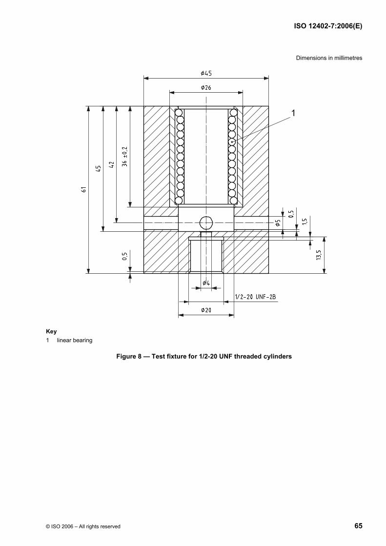
ISO 12402-7:2006(E)
© ISO 2006 – All rights reserved 65
Dimensions in millimetres
Key 1 linear bearing
Figure 8 — Test fixture for 1/2-20 UNF threaded cylinders

ISO 12402-7:2006(E)
66 © ISO 2006 – All rights reserved
Dimensions in millimetres
Key 1 linear bearing
Figure 9 — Test fixture for 3/8-24 UNF threaded cylinders
The test fixture with cylinder shall be mounted on a rigid test fixture stand so that the cylinder axis is vertical. The test fixture stand (locating block support) shown in Figure 10 meets the intent of the requirement.

ISO 12402-7:2006(E)
© ISO 2006 – All rights reserved 67
Dimensions in millimetres
Figure 10 — Test fixture stand
The pierce pin shall be secured in a pierce-pin holder so that the pin is perpendicular to and centred in the holder, with an exposed pin length of (9,0 ± 0,5) mm. The holder shown in Figure 11 meets the intent of the requirement.

ISO 12402-7:2006(E)
68 © ISO 2006 – All rights reserved
Dimensions in millimetres
Figure 11 — Pierce-pin holder for “Halkey mini pierce pin”
The pierce-pin holder shall be secured to the load cell of a constant rate extension (CRE) machine. The pierce-pin holder with pierce pin shall be mated with the test fixture so that the pin is perpendicular to and centred over the piercing area of the cylinder cap. The test arrangement shown in Figure 12 complies with the requirement.

ISO 12402-7:2006(E)
© ISO 2006 – All rights reserved 69
Key 1 pierce-pin holder 2 linear bearing 3 locating block 4 standard pierce pin 5 test cylinder 6 locating block support
Figure 12 — Cylinder piercing force test arrangement
The pierce pin shall be carefully moved toward the surface of the cap of the cylinder without making contact with the cap of the cylinder. Any cylinder sample that is touched by the pierce pin during this initial stage shall not be used for data acquisition. The pierce pin shall be driven into the cylinder cap at a rate of (30 ± 1,5) mm/min until the chamfered point of the pierce pin completely penetrates the top surface of the cap, and until the pierce pin traverses a distance of at least 3,3 mm, measured from the point of initial contact of the pierce pin with the cap. A graph of pierce force (Y axis) versus distance traversed (X axis) shall be recorded. The maximum load achieved during the test shall be recorded as the piercing force for the sample. The work (area under the curve) required to achieve penetration, measured from vertical intercept at 2,2 N to vertical intercept at 3,0 mm distance traversed shall be determined from the graph. A new pierce pin shall be used for each 50 cylinders.
4.12.2.2.4.2 Test sample
100 filled cylinders shall be taken at random.

ISO 12402-7:2006(E)
70 © ISO 2006 – All rights reserved
4.12.2.2.5 Leakage test
4.12.2.2.5.1 Procedure
All cylinders in the production batch shall be tested for tightness. The cylinders shall be complete in all respects but may or may not be marked. Leaking cylinders shall be identified by weighing before and after heating in an oven for 96 h at (65 8
0+ ) °C; or by observation of any bubble in a 1 min period when immersed in
water containing 1 % of a 25 % Aerosol OT clear solution (or equivalent) at (50 ± 5) °C; or by any equally sensitive method. Any cylinders found to be leaking shall be rejected. The leak-free cylinders shall be marked with the minimum gross mass, or they may be classified into batches of similar minimum gross mass ranges and the batches so marked.
4.12.2.2.5.2 Test sample for determination of gas cylinder gross mass
20 units shall be taken at random, if classified, from each similar minimum gross mass batch.
4.12.2.2.6 Test for mass of gas charge or filling pressure
4.12.2.2.6.1 Procedure
The test unit shall be weighed to two places of decimals (grams). The gas shall be released and the unit reweighed. When the filling is a liquefied gas, care shall be taken to ensure that the cylinder is wiped clean of condensation, is empty and free of solidified gas, before reweighing. The difference between the full and empty masses shall be the mass of the gas charge. When filled with a permanent gas, the volume of the cylinder shall be determined as in 4.12.2.2.7 and the gas pressure calculated using the appropriate compressibility factor for the gas.
4.12.2.2.6.2 Test sample
Eight units shall be taken at random.
4.12.2.2.7 Cylinder volume and (for liquefied gases) maximum filling density test
4.12.2.2.7.1 Procedure
The volume of the test unit (ml) shall be determined with the cap in place. The empty cylinder shall be weighed and the mass (grams) recorded. The cylinder shall be filled with water and reweighed, and the mass of the water and thus the volume determined. For permanent gas fillings, the volume so determined shall be used in the calculation to evaluate the gas pressure. The filling density, ρ, for liquified gases shall be determined as follows:
mV
ρ =
where
m is the mass of gas, determined according to 4.12.2.2.6;
V is the cylinder volume.
4.12.2.2.7.2 Test sample
Eight units shall be taken at random. The test sample for 4.12.2.2.6 may be used for this test.

ISO 12402-7:2006(E)
© ISO 2006 – All rights reserved 71
4.12.2.2.8 Dimensions and workmanship tests
4.12.2.2.8.1 General
Table 23 gives a description of defects.
4.12.2.2.8.2 Procedure
a) Inspection for defects D 1 to D 4 and dimensional checks:
The test unit shall be visually examined and dimensionally checked using standard measuring equipment. The equipment used shall always conform to the appropriate calibration schedule.
b) Inspection for defects D 5 and M 4:
Prior to filling, the inside of the cylinder may be inspected using any suitable optical equipment. On completion, the cylinder shall be sectioned to reveal the entire interior surface.
c) Inspection for defects M 1 to M 3:
These defects shall be observed by the naked eye at normal reading distance.
4.12.2.2.8.3 Test sample
20 units shall be taken at random and shall be inspected for defects D 1 to D 4 and M 1 to M 3. For inspection for defects D 5 and M 4, the test sample shall be eight units and may be the same sample used in 4.12.2.2.6. The units shall be complete in all respects.
4.12.2.2.9 Corrosion resistance test
4.12.2.2.9.1 Procedure
The procedure shall be in accordance with ISO 9227.
The test period shall not be less than 96 h.
4.12.2.2.9.2 Test sample
Eight units, complete in all respects including markings, shall be taken at random.

ISO 12402-7:2006(E)
72 © ISO 2006 – All rights reserved
Table 23 — Visual examination, list of defects
No. Major defect (D) No. Minor defect (M)
D 1 Surface with cracks, nicks, pits or indentations or other defects which are considered to be significant enough to compromise the safety or effective use of the cylinder.
M 1 Surface is unclean, or contains minor burrs, nicks, sharp edges or embedded foreign matter not significant enough to compromise the safety or effective use of the cylinder.
D 2 Sealing cap not securely attached. M 2 Plating or chromate coating discoloured or not uniformly applied.
D 3 Plating missing on body of cylinder. M 3 Plating on thread less than in drawing, but not absent.
D 4 Threads incorrect or damaged as determined by GO and NoGO gauges.
D 5 Internal contaminants: loose material (rust, debris, scale, liquid) considered to be of sufficient size or quantity to compromise the free flow of contents through a 1,5 mm (1/16 in) diameter opening.
M 4 Internal contaminants: traces of loose material or liquid, light rust or firmly attached light scale.
4.12.3 Marking
The cylinders shall be marked, directly on the surface by any suitable means, or on a label fixed to the surface. The markings shall be permanent, legible and durable when subjected to normal handling, transport and exposure to the environment over the life of the cylinder and shall include at least the following:
a) nominal gas charge or gas pressure, chemical symbol of gas;
b) minimum gross weight of cylinder;
c) manufacturer's symbol, part No., country, month/year of filling;
d) cautionary statements: as a minimum, “Do not heat.”.

ISO 12402-7:2006(E)
© ISO 2006 – All rights reserved 73
Annex A (informative)
Mildew resistance of materials: Soil burial method
A.1 General
This annex describes a method for determining the resistance of materials to fungus attack when subjected to severe moulding conditions from long exposure in severe climate as specified in FTMS (Federal Test Method Standard) 191A, Method 5762. See Table 12.
A.2 Specimens
A.2.1 Viability control specimens
Control specimens shall be untreated cotton cloth of about 400 g/m2 to 475 g/m2.
A.2.2 Test specimens
Double test specimens shall be taken from the sample unit. Half of the specimens shall be retained unburied and subjected to the same physical tests as the buried specimens for the purpose of comparison to determine the degree of mildew resistance of the affected specimens.
A.3 Apparatus
A.3.1 Soil bed
A.3.1.1 The soil shall be a compost comprising equal parts of
a) good top soil (soil with high clay content should not be used);
b) well rotted and shredded manure of leaf mould;
c) coarse sand (sand of a 10 or 40 mesh is best).
The soil shall be rich with microbial life which decomposes cellulose as determined in A.4.4. The soil shall not tend to pack closely or become sticky when damp. The soil mixture shall be aged for three months at 27 °C to 30 °C before use and mixed after each two weeks of aging. If at the end of three months aging the soil fails to degrade untreated cloth when tested as specified in A.4.4, the aging should be continued until it does. Aged soil may be stored and reused indefinitely so long as activity can be demonstrated when tested as specified in A.4.4.
A.3.1.2 The soil shall be maintained at between 20 % and 30 % moisture, based on the dry weight of the soil, at a temperature of 28 °C to 30 °C. Water lost during use due to evaporation shall be replaced without deforming the soil bed. If the surrounding atmosphere is maintained at 85 % to 95 % relative humidity, this loss is negligible.
A.3.1.3 The soil shall be adjusted to a pH between 6,5 and 7,5. Periodic tests and adjustments should be made to maintain the soil within the desired range by addition of appropriate amounts of calcium carbonate or agricultural ground limestone to raise the pH, or flowers of sulphur to lower the pH.

ISO 12402-7:2006(E)
74 © ISO 2006 – All rights reserved
A.3.2 Soil container
The container shall be of wood (cypress or redwood recommended) or other suitable material such as plastic or stainless steel in a size which is convenient to handle and having a depth of at least 125 mm.
A.3.3 Incubator
The incubator is a room or cabinet maintained at a temperature of 28 °C to 30 °C, and a relative humidity of 85 % to 95 %.
A.4 Procedure
A.4.1 Before exposure to mildew, the specimens shall be leached by submerging in a tank containing 4 l of water with a continuous flow of water to the bottom at 27 °C to 29 °C and a rate of five changes per hour. The specimens shall be suspended for 24 h such that all surfaces are exposed to the water and do not come into contact with the container or each other. At the end of the leaching period, the specimens shall be air dried.
A.4.2 The resistance to mildew shall be determined by the change in tensile strength and permeability to CO2.
A.4.3 The specimens shall be exposed in the incubator for 12 weeks.
A.4.4 Untreated cotton cloth control specimens shall be exposed in the soil bed every 10 d throughout the period of test in order to verify the microbial activity of the soil. The soil shall be considered to be satisfactory if the untreated controls lose not less than 50 % of their tensile strength in 5 d.
A.4.5 After being wet-out (see A.4.1), the specimen shall be buried in the soil. The specimen shall be placed flat on a 100 mm bed of soil, spaced at least 25 mm from any other specimen and covered with 25 mm of loose soil.
A.4.6 At the end of the exposure period, the specimen shall be removed from the soil bed and, if not extensively degraded, gently washed to remove soil, air-dried and then conditioned to equilibrium according to the tensile strength or permeability test method, as applicable. At the end of the conditioning period, the same physical tests shall be conducted on exposed and unexposed specimens for the purpose of comparison in determining the degree of mildew resistance of the affected specimens.
A.4.7 The change in tensile strength or other characteristic of the specimen shall be calculated as follows:
( 100)O EO
θ − ×=
where
θ is the change in value of the characteristic, in percent;
O is the value before exposure to mildew;
E is the value after exposure to mildew.
A.5 Report
The change in breaking strength or other physical characteristic of the sample unit after exposure to mildew shall be the average of the results obtained from the specimens tested and shall be reported as “percentage change” to the nearest 1 %.

ISO 12402-7:2006(E)
© ISO 2006 – All rights reserved 75
Annex B (informative)
Abrasion resistance of cloth: Oscillatory method
(Wyzenbeek method)
B.1 General
This annex specifies a method for determining the abrasion resistance of woven fabrics when subjected to unidirectional rubbing action under controlled conditions of pressure, tension, and abrasive action. This method follows that of FTMS (Federal Test Method Standard) 191A, Method 5304.
B.2 Apparatus
B.2.1 Oscillatory cylinder
B.2.1.1 This is an oscillating cylinder section with edge clamps to permit mounting of a sheet of abrasive material over its curved surface. Three or four specimen-holding arms shall be provided to permit testing of several specimens simultaneously.
B.2.1.2 Each arm shall consist of a set of controlled tension clamps and a controlled pressure pad. Tension on the specimen shall be adjusted by use of a calibrated sliding weight on a bar attached to the forward specimen clamp. The rear clamp shall butt against a thumb screw to provide for taking up the slack of the specimen. The pressure pad, made of sponge rubber, shall be fitted to a pressure bar at the top of the specimen holding arm. A second calibrated sliding weight shall furnish the desired pressure between the pad and the cylinder section.
B.2.1.3 The cylinder section shall have a diameter of 152 mm, and the rubber pad, 50 mm × 50 mm in dimension, shall be shaped to the curve of the cylinder surface. The section shall oscillate through a 75 mm long arc at the rate of 90 cycles (double rubs) per minute.
B.2.1.4 Suspended over the drum shall be two slotted vacuum pipes which shall serve to remove lint and dust particles.
B.2.2 An automatic counter shall be provided for recording the number of oscillations. The abradant for testing material to Tables 12 and 13 shall be No. 8 cotton duck, (610 ± 25) g/m2, and for testing material to Tables 14, 15 and 20 shall be No. 0 emery paper.
B.2.3 An illustration of the apparatus is shown in Figure B.1.
B.2.4 An abrasion machine of the type described in this method is manufactured by J K Technologies Inc., 2524 S. 8000 West Road, Kankakee, IL 60901 USA, Phone: (815) 933-8712.3)
3) This information is given for the convenience of users of this part of ISO 12402 and does not constitute an endorsement by ISO of the product named. Equivalent products may be used if they can be shown to lead to the same results.
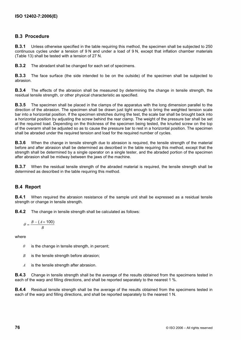
ISO 12402-7:2006(E)
76 © ISO 2006 – All rights reserved
B.3 Procedure
B.3.1 Unless otherwise specified in the table requiring this method, the specimen shall be subjected to 250 continuous cycles under a tension of 9 N and under a load of 9 N, except that inflation chamber materials (Table 13) shall be tested with a tension of 27 N.
B.3.2 The abradant shall be changed for each set of specimens.
B.3.3 The face surface (the side intended to be on the outside) of the specimen shall be subjected to abrasion.
B.3.4 The effects of the abrasion shall be measured by determining the change in tensile strength, the residual tensile strength, or other physical characteristic as specified.
B.3.5 The specimen shall be placed in the clamps of the apparatus with the long dimension parallel to the direction of the abrasion. The specimen shall be drawn just tight enough to bring the weighted tension scale bar into a horizontal position. If the specimen stretches during the test, the scale bar shall be brought back into a horizontal position by adjusting the screw behind the rear clamp. The weight of the pressure bar shall be set at the required load. Depending on the thickness of the specimen being tested, the knurled screw on the top of the overarm shall be adjusted so as to cause the pressure bar to rest in a horizontal position. The specimen shall be abraded under the required tension and load for the required number of cycles.
B.3.6 When the change in tensile strength due to abrasion is required, the tensile strength of the material before and after abrasion shall be determined as described in the table requiring this method, except that the strength shall be determined by a single operator on a single tester, and the abraded portion of the specimen after abrasion shall be midway between the jaws of the machine.
B.3.7 When the residual tensile strength of the abraded material is required, the tensile strength shall be determined as described in the table requiring this method.
B.4 Report
B.4.1 When required the abrasion resistance of the sample unit shall be expressed as a residual tensile strength or change in tensile strength.
B.4.2 The change in tensile strength shall be calculated as follows:
( 100)B AB
θ − ×=
where
θ is the change in tensile strength, in percent;
B is the tensile strength before abrasion;
A is the tensile strength after abrasion.
B.4.3 Change in tensile strength shall be the average of the results obtained from the specimens tested in each of the warp and filling directions, and shall be reported separately to the nearest 1 %.
B.4.4 Residual tensile strength shall be the average of the results obtained from the specimens tested in each of the warp and filling directions, and shall be reported separately to the nearest 1 N.

ISO 12402-7:2006(E)
© ISO 2006 – All rights reserved 77
Figure B.1 — Abrasion machine with overarms raised

ISO 12402-7:2006(E)
78 © ISO 2006 – All rights reserved
Annex C (informative)
Example of a design drawing
NOTE The letters within the circles refer to 4.12.1.3.1.
Figure C.1

ISO 12402-7:2006(E)
© ISO 2006 – All rights reserved 79
Bibliography
[1] ISO 12401, Small craft — Deck safety harness and safety line for use on recreational craft — Safety requirements and test methods
[2] ISO/IEC 17025, General requirements for the competence of testing and calibration laboratories
[3] ISO 12402-10, Personal flotation devices — Part 10: Selection and application of personal flotation devices and other relevant devices
[4] Declaration of Helsinki: Ethical principles for medical research involving human subjects, World Medical Association
ISO 12402-7:2006(E)
ICS 13.340.70 Price based on 79 pages
© ISO 2006 – All rights reserved