pet/ct facility design - aapm.org · pdf filepet/ct facility design 2010 american college of...
TRANSCRIPT

PET/CT Facility PET/CT Facility DesignDesign
2010201020102010American College of Medical American College of Medical
PhysicsPhysics
Jon A. Anderson, PhD Jon A. Anderson, PhD
ACMP, 2010 [email protected] 1
Department of RadiologyDepartment of RadiologyThe University of Texas Southwestern Medical Center at DallasThe University of Texas Southwestern Medical Center at Dallas

What Is Different When You Have PET/CT i Y F ilit ?PET/CT in Your Facility?1) 511 keV energy-increases exposure rate from doses,increases exposure rate from doses, patients-greatly increases thickness of required hi ldi d t di tishielding compared to diagnostic rooms
2)Requirements for patient handling during injection and uptake phase
3) Combined modality scanners3) Combined modality scanners (PET/CT) require consideration of both gamma-ray and x-ray hazards
ACMP, 2010 [email protected] 24) You can affect neighboring modalities
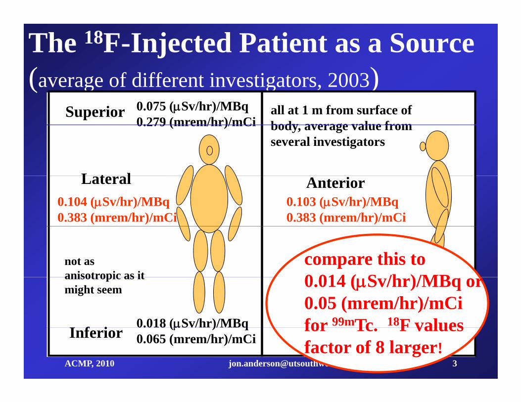
The 18F-Injected Patient as a Source ( f diff i i 2003)(average of different investigators, 2003)
0.075 (Sv/hr)/MBq0.279 (mrem/hr)/mCi
all at 1 m from surface of body average value from
Superior0.279 (mrem/hr)/mCi body, average value from
several investigators
L t l0.103 (Sv/hr)/MBq0.383 (mrem/hr)/mCi
0.104 (Sv/hr)/MBq0.383 (mrem/hr)/mCi
AnteriorLateral
not as anisotropic as it
compare this to 0 014 ( S /h )/MB
0.018 (Sv/hr)/MBqI f i
anisotropic as it might seem 0.014 (Sv/hr)/MBq or
0.05 (mrem/hr)/mCifor 99mTc 18F values
ACMP, 2010 [email protected] 3
( ) q0.065 (mrem/hr)/mCiInferior for Tc. F values
factor of 8 larger!
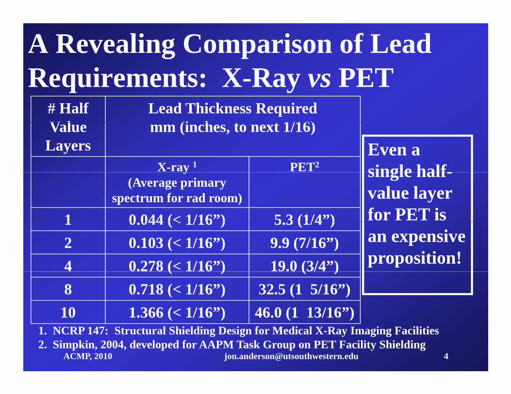
A Revealing Comparison of Lead R i t X R PETRequirements: X-Ray vs PET
# Half V l
Lead Thickness Required(i h t t 1/16)Value
Layersmm (inches, to next 1/16)
X-ray 1 PET2Even a single half-y
(Average primary spectrum for rad room)
1 0 044 (< 1/16”) 5 3 (1/4”)
single half-value layer for PET is 1 0.044 (< 1/16 ) 5.3 (1/4 )
2 0.103 (< 1/16”) 9.9 (7/16”)4 0.278 (< 1/16”) 19.0 (3/4”)
an expensive proposition!( ) ( )
8 0.718 (< 1/16”) 32.5 (1 5/16”)10 1.366 (< 1/16”) 46.0 (1 13/16”)
ACMP, 2010 [email protected] 4
1. NCRP 147: Structural Shielding Design for Medical X-Ray Imaging Facilities2. Simpkin, 2004, developed for AAPM Task Group on PET Facility Shielding
A Revealing Comparison of Lead R i t X R PET
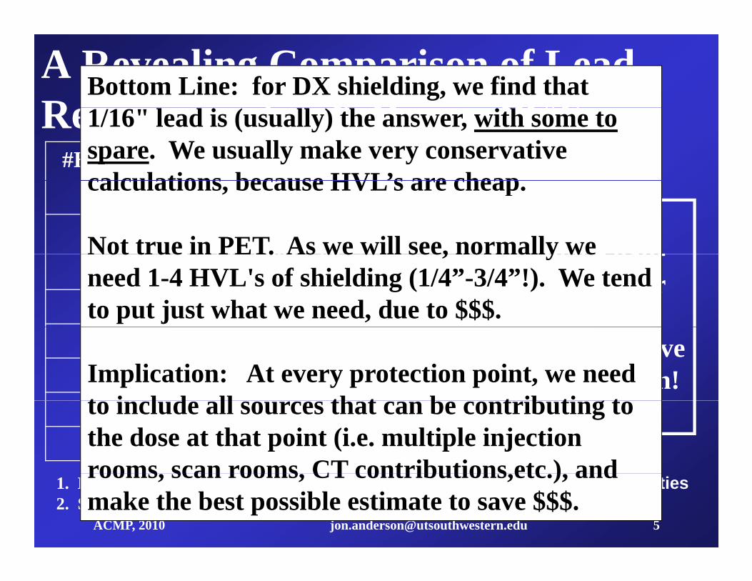
Bottom Line: for DX shielding, we find that Requirements: X-Ray vs PET
#HVL's Lead Thickness Required(i t t 1/16)
1/16" lead is (usually) the answer, with some to spare. We usually make very conservative calculations because HVL’s are cheapmm (in, to next 1/16)
X-ray 1(average primary for
PET2 Even a single half-
calculations, because HVL’s are cheap.
Not true in PET. As we will see, normally we(average primary for rad room)
1 0.044 (< 1/16) 5.3 (1/4)
single half-value layer for PET is
Not true in PET. As we will see, normally we need 1-4 HVL's of shielding (1/4”-3/4”!). We tend to put just what we need, due to $$$.2 0.103 (< 1/16) 9.9 (7/16)4 0.278 (< 1/16) 19.0 (3/4)
an expensive proposition!Implication: At every protection point, we need
t i l d ll th t b t ib ti t8 0.718 (< 1/16) 32.5 (1 5/16)10 1.366 (< 1/16) 46.0 (1 13/16)
to include all sources that can be contributing to the dose at that point (i.e. multiple injection rooms scan rooms CT contributions etc ) and
ACMP, 2010 [email protected] 5
1. NCRP 147: Structural Shielding Design for Medical X-Ray Imaging Facilities2. Simpkin, 2004, developed for AAPM Task Group on PET Facility Shielding
rooms, scan rooms, CT contributions,etc.), and make the best possible estimate to save $$$.

Workflow at the PET Center (FDG Whole Body Scans)(FDG Whole Body Scans)
Receive dosesArrival of patient* *Injection of Pt
Uptake of pharmaceutical
Assay of dosePt instruction and prep
30-90 min
* *
5-20 mCi
Transport Pt to scanner
Have Pt empty bladder
**
5 20 mCi
Position Pt
Scan5-20 min
5-10 min * * steps with highest technologist* QA Check of ScanRelease Pt
Read study
technologist exposure
*
ACMP, 2010 [email protected] 6
Distribute to PACS or Media
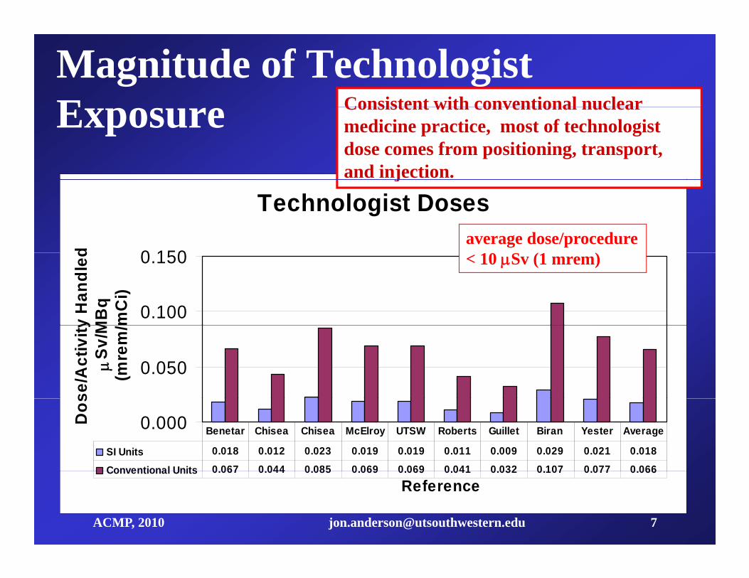
Magnitude of Technologist E Consistent with conventional nuclearExposure Consistent with conventional nuclear
medicine practice, most of technologist dose comes from positioning, transport, and injection.
Technologist Doses
0 150d
j
average dose/procedure
0.100
0.150
y H
andl
edM
Bq
mC
i)
< 10 Sv (1 mrem)
0.050
se/A
ctiv
ity
Sv/M
(mre
m/
0.000Dos
SI Units 0.018 0.012 0.023 0.019 0.019 0.011 0.009 0.029 0.021 0.018
Conventional Units 0.067 0.044 0.085 0.069 0.069 0.041 0.032 0.107 0.077 0.066
Benetar Chisea Chisea McElroy UTSW Roberts Guillet Biran Yester Average
ACMP, 2010 [email protected] 7
ReferenceConventional Units 0.067 0.044 0.085 0.069 0.069 0.041 0.032 0.107 0.077 0.066

More on Technologist Exposure
1) Individual technologist dose should drop as experience increasesp
Over a two year period with the same technologists, we saw a 40% d i di ti d it ti it h dl ddecrease in radiation dose per unit activity handled.
2) For 0.018 Sv/(MBq injected) 370 MBq (10 mCi) injected/pt 10 pt/day
Yearly: 16.6 mSv (1660 mrem) (<5 rem, >ALARA trigger) 9 Months: 12.5 mSv (1250 mrem) (> declared pregnancy limit)
ACMP, 2010 [email protected] 8

Operating Suggestions to Minimize T h l i t DTechnologist DoseMinimize handling time. Use unit doses.g
Use tungsten syringe shields, employ syringe carriers, i i i h dlitransport carts, etc. to minimize handling exposure.
Instruct patient before injection Minimize contactInstruct patient before injection. Minimize contact afterward.
Establish IV access with butterfly infusion set.
ACMP, 2010 [email protected] 9
Use other personnel for hot patient transport.

PET Facility Tour: University of Texas Southwestern Medical Center at DallasSouthwestern Medical Center at Dallas(2001-2007) Strip shopping center, uncontrolled
occupancies on both sides
Future CameraRoom Office 1
Dock Laun
d ry
ScanUtility Reading
Room
Radioactive Materials
Office 3Offi 2
Hot Lab
L
S idor
East Corridor
ScanRoom 1
Office 2Injection#2
Injection#1
HotToilet
ScanRoom 2
Sout
h Co
rri
Control
West Corridor
BreakRoomStorage Reception &
WaitingBusiness
Office
Patients
ACMP, 2010 [email protected] 10
Room WaitingOffice
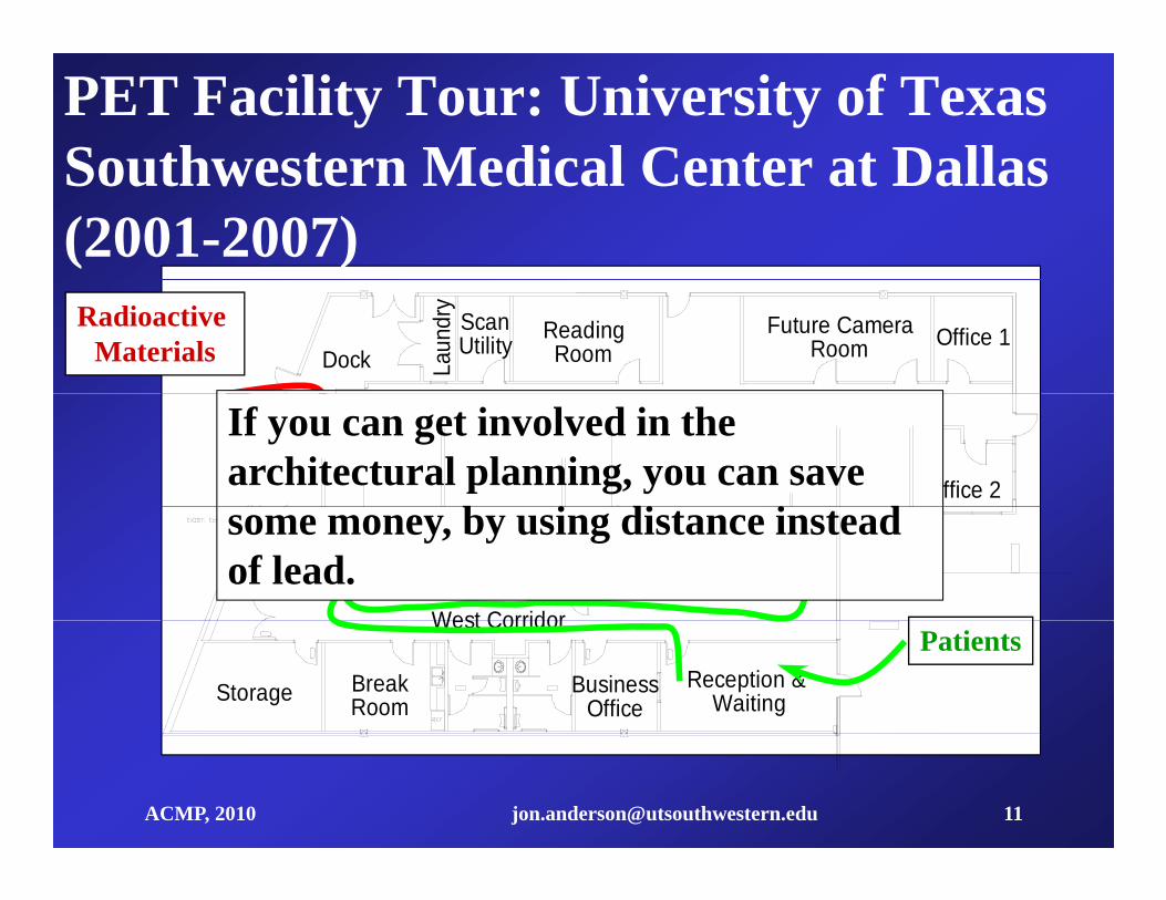
PET Facility Tour: University of Texas Southwestern Medical Center at DallasSouthwestern Medical Center at Dallas(2001-2007)
Future CameraRoom Office 1
Dock Laun
d ry
ScanUtility Reading
RoomRadioactive
Materials
ScanR 1
Office 3Office 2Injection
Hot LabScan
R 2 orrid
o r
East CorridorIf you can get involved in the architectural planning, you can save
i i iRoom 1
West Corridor
Injection#2
Injection#1
HotToilet
Room 2
Sout
h Co
Controlsome money, by using distance instead of lead.
West Corridor
BreakRoomStorage Reception &
WaitingBusiness
Office
Patients
ACMP, 2010 [email protected] 11

Hot Lab Details: Dose Storage AArea
Notes:1) Floor protection (containers
eigh > 66 lbs)weigh > 66 lbs)2) Space needed depends on how often deliveriesoften deliveries are made; may have >100 mCi here at a time, ,even for one scanner3) Extra
ACMP, 2010 [email protected] 12
shielding may be required

Hot Lab Details: Dose Assay and P ti APreparation Area
Notes:1) Calibrator )convenient to dose storage2) L Block close to calibrator3) Note use of
ispecial PET carrier for syringe4) Note L4) Note L Block: thick window, 2" lead 2" lead
ACMP, 2010 [email protected] 13
lead, 2 lead wrap-around
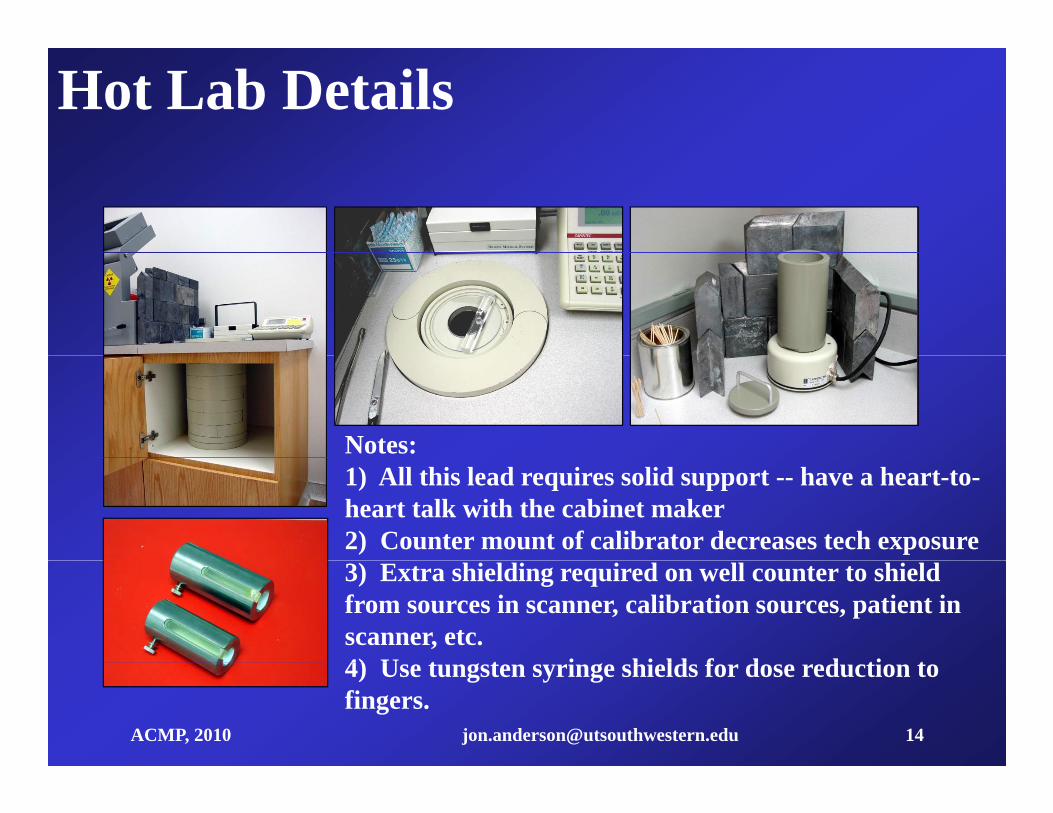
Hot Lab Details
Notes: 1) All this lead requires solid support -- have a heart-to-heart talk with the cabinet maker2) Counter mount of calibrator decreases tech exposure3) Extra shielding required on well counter to shield from sources in scanner, calibration sources, patient in scanner, etc.4) U t t i hi ld f d d ti t
ACMP, 2010 [email protected] 14
4) Use tungsten syringe shields for dose reduction to fingers.
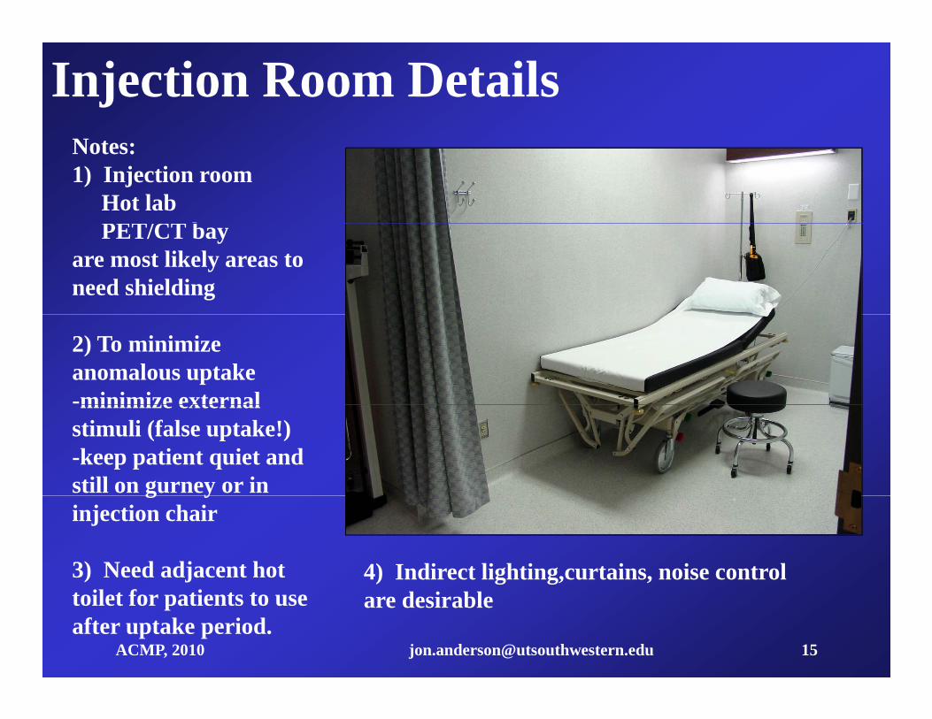
Injection Room DetailsNotes:1) Injection room
Hot labPET/CT bPET/CT bay
are most likely areas to need shielding
2) To minimize anomalous uptake-minimize externalminimize external stimuli (false uptake!)-keep patient quiet and still on gurney or in g yinjection chair
3) Need adjacent hot 4) Indirect lighting,curtains, noise control
ACMP, 2010 [email protected] 15
toilet for patients to use after uptake period.
are desirable
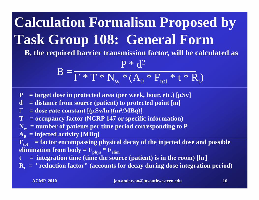
Calculation Formalism Proposed by T k G 108 G l FTask Group 108: General Form
B, the required barrier transmission factor, will be calculated asP * d2
B = P * d2
* T * Nw * A0 * Ftot * t * Rt)P = target dose in protected area (per week, hour, etc.) [Sv]d = distance from source (patient) to protected point [m] = dose rate constant [(Sv/hr)(m2/MBq)] dose rate constant [(Sv/hr)(m /MBq)]T = occupancy factor (NCRP 147 or specific information)Nw = number of patients per time period corresponding to PA0 = injected activity [MBq]0Ftot = factor encompassing physical decay of the injected dose and possible elimination from body = Fphys * Felimt = integration time (time the source (patient) is in the room) [hr]
ACMP, 2010 [email protected] 16
Rt = "reduction factor" (accounts for decay during dose integration period)

Site Evaluation for PET ShieldingUses of adjacent spaces (including above and below) and occupancy factors for them
# patients/weekisotopes to be used, activity/ptt f PET t di t b f d (b i WB di )types of PET studies to be performed (brains, WB, cardiac)uptake time and scan time for this equipment/study/center
dose delivery schedule (once a day?, multiples?); maximum activity on hand
CT technique factors (kVp, mAs/scan [depends of # beds])# scans per patient (additional diagnostic scans?)
t f " PET" CT kl d t d
ACMP, 2010 [email protected] 17
amount of "non-PET" CT workload expected
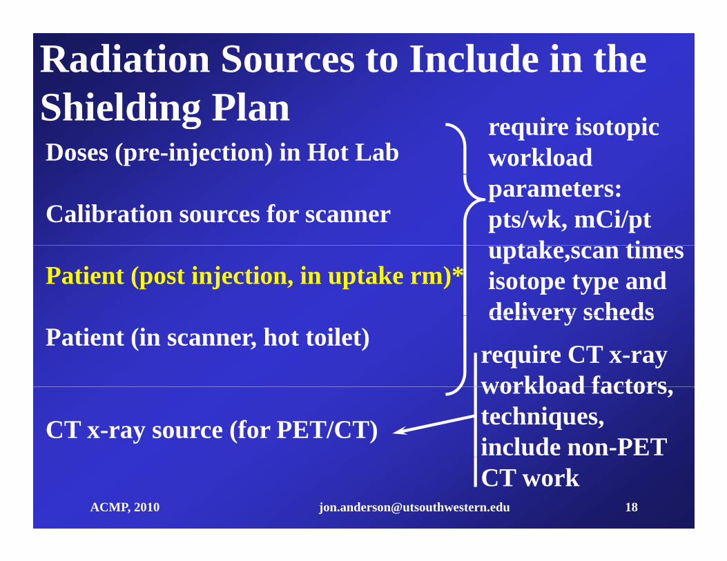
Radiation Sources to Include in the Shielding PlanShielding PlanDoses (pre-injection) in Hot Lab
require isotopic workload
Calibration sources for scanner parameters:pts/wk, mCi/pt
t k tiPatient (post injection, in uptake rm)*
uptake,scan timesisotope type and delivery scheds
Patient (in scanner, hot toilet)delivery scheds
require CT x-ray workload factors
CT x-ray source (for PET/CT)
workload factors, techniques, include non-PET
ACMP, 2010 [email protected] 18
CT work
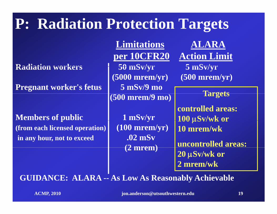
P: Radiation Protection TargetsLimitations ALARAper 10CFR20 Action Limit
Radiation workers 50 mSv/yr 5 mSv/yrRadiation workers 50 mSv/yr 5 mSv/yr(5000 mrem/yr) (500 mrem/yr)
Pregnant worker's fetus 5 mSv/9 mo Targets(500 mrem/9 mo)
Members of public 1 mSv/yr
Targets
controlled areas:100 Sv/wk orp y
(from each licensed operation) (100 mrem/yr)in any hour, not to exceed .02 mSv
(2 mrem)
100 Sv/wk or 10 mrem/wk
uncontrolled areas: (2 mrem)20 Sv/wk or 2 mrem/wk
ACMP, 2010 [email protected] 19
GUIDANCE: ALARA -- As Low As Reasonably Achievable

N: Maximum Workload EstimationPET Facility Throughput Example:
90 Minute Uptake, 30 Minute Scan15
15 i /d
9
11
13
umbe
r 15 patients/day three uptake rooms
5
7
9
atie
nt N
PhaseUptake
1
3Pa
pScanning
7:00 8:00 9:00 10:00 11:00 12:00 13:00 14:00 15:00 16:00 17:00
Time of Day
ACMP, 2010 [email protected] 20
#pts/day = (tworkday - tuptake)/tscan_rm # uptake areas = tuptake/tscan_rm
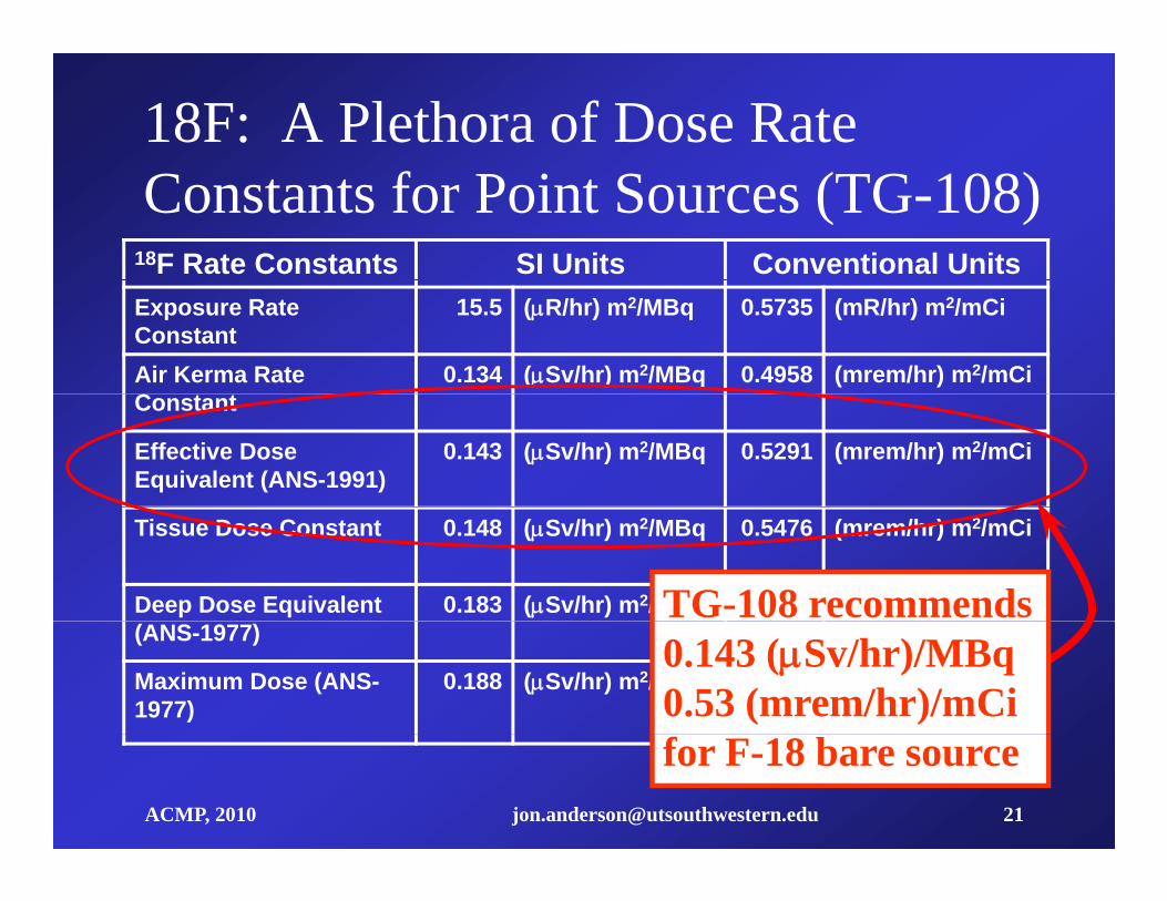
18F: A Plethora of Dose Rate Constants for Point Sources (TG-108)
18F Rate Constants SI Units Conventional UnitsExposure Rate Constant
15.5 (R/hr) m2/MBq 0.5735 (mR/hr) m2/mCi
Air Kerma Rate C
0.134 (Sv/hr) m2/MBq 0.4958 (mrem/hr) m2/mCiConstant
Effective Dose Equivalent (ANS-1991)
0.143 (Sv/hr) m2/MBq 0.5291 (mrem/hr) m2/mCi
Tissue Dose Constant 0.148 (Sv/hr) m2/MBq 0.5476 (mrem/hr) m2/mCi
Deep Dose Equivalent 0.183 (Sv/hr) m2/MBq 0.6771 (mrem/hr) m2/mCiTG-108 recommends(ANS-1977)
Maximum Dose (ANS-1977)
0.188 (Sv/hr) m2/MBq 0.6956 (mrem/hr) m2/mCi0.143 (Sv/hr)/MBq0.53 (mrem/hr)/mCi
ACMP, 2010 [email protected] 21
for F-18 bare source
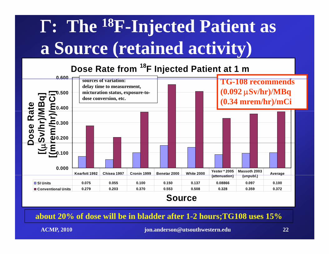
: The 18F-Injected Patient as a Source (retained activity)
Dose Rate from 18F Injected Patient at 1 m0.600
a Source (retained activity)f i ti TG 108 d
0.400
0.500
0.600
ate
MB
q]/m
Ci]
sources of variation:delay time to measurement, micturation status, exposure-to-dose conversion, etc.
TG-108 recommends(0.092 Sv/hr)/MBq (0.34 mrem/hr)/mCi
0.200
0.300
Dos
e R
aSv
/hr)
/Mre
m/h
r)/
0.000
0.100
D[( [(m
r
Kearfott 1992 Chisea 1997 Cronin 1999 Benetar 2000 White 2000 Yester * 2005 ( tt ti )
Massoth 2003 ( bl ) Average
Source
SI Units 0.075 0.055 0.100 0.150 0.137 0.08866 0.097 0.100Conventional Units 0.279 0.203 0.370 0.553 0.508 0.328 0.359 0.372
(attenuation) (unpubl.) g
ACMP, 2010 [email protected] 22
about 20% of dose will be in bladder after 1-2 hours;TG108 uses 15%
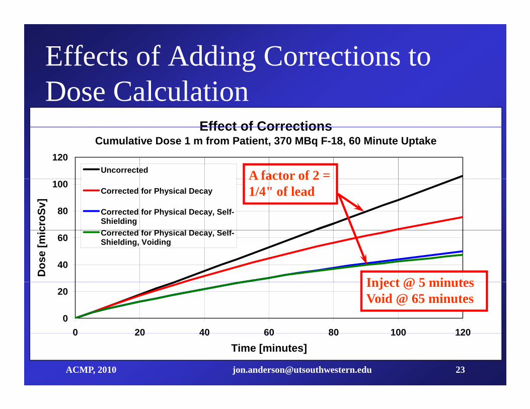
Effects of Adding Corrections to
Effect of Corrections
Dose CalculationEffect of Corrections
Cumulative Dose 1 m from Patient, 370 MBq F-18, 60 Minute Uptake120
Uncorrected A factor of 2 =
80
100
croS
v]
Corrected for Physical Decay
Corrected for Physical Decay, Self-ShieldingC t d f Ph i l D S lf
A factor of 2 1/4" of lead
40
60
Dos
e [m
ic Corrected for Physical Decay, Self-Shielding, Voiding
Inject @ 5 minutes
0
20
0 20 40 60 80 100 120
Inject @ 5 minutesVoid @ 65 minutes
ACMP, 2010 [email protected] 23
0 20 40 60 80 100 120Time [minutes]

Going from Barrier Transmission M t C l
Lead
to Shield Thickness (PET)Monte Carlocalculations by Douglas
1.0000Simpkin (2004)Monte Carlo Simulation
(Broad Parallel Beam)
Constant TVL 16 6 mm B
0.0100
0.1000
mis
sion
Constant TVL 16.6 mm
x B( )1
lnB
1
0.0010
Tran
sm
Curves and fitting f i
0.00010 5 10 15 20 25 30 35 40 45 50
Thickness(mm)
parameters for iron and concrete are also found in the
ACMP, 2010 [email protected] 24
Thickness(mm)
TG 108 report

Example 1: Uptake RoomA t ll d ithProtection Goal: 6 An uncontrolled area with 100% occupancy is 4m from the patient 40
Protection Goal:
Dis tance:
P 20 10 6 Sv
d 4 m
09210 6 Sv m2 from the patient. 40
patients a week are injected in this room with
Gamma Constant:
Occupancy:
.09210hr 106Bq
T 1 j555 MBq (15 mCi) of FDG and held for a 1hr
Number of Patients per W eek:
Injected Activity:
Nw 40
A0 555 106Bq
uptake time.
How much shielding?
Decay/Elimination:
Source Duration:
Reduction Factor:
F 1
t 1hr
R t( ) 0 831 How much shielding?
Ans: 1.2 cm of Pb or 15.2
Reduction Factor: R t( ) 0.831
BrP d2
T Nw A0 F R t( ) t Br 0.188
ACMP, 2010 [email protected] 25
cm of concretexPb Br 1.184cm xconc Br 15.165cm
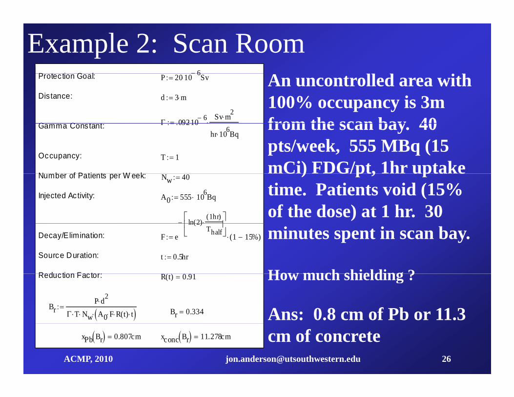
Example 2: Scan RoomP t ti G l 6 An uncontrolled area with
100% occupancy is 3m from the scan bay 40
Protec tion Goal:
Dis tance:
G C t t
P 20 10 6 Sv
d 3 m
09210 6Sv m2
from the scan bay. 40 pts/week, 555 MBq (15 mCi) FDG/pt, 1hr uptake
Gamma Constant:
Occupancy:
N b f P ti t W k
.09210hr 106Bq
T 1
C ) G/pt, upta etime. Patients void (15% of the dose) at 1 hr. 30
Number of Patients per W eek:
Injected Activity:
Nw 40
A0 555 106Bq
ln 2( )1hr( )
minutes spent in scan bay.
How much shielding ?
Decay/Elimination:
Source Duration:
Reduction Factor:
F e
ln 2( )Thalf
1 15%( )
t 0.5hr
( ) How much shielding ?
Ans: 0.8 cm of Pb or 11.3
Reduction Factor: R t( ) 0.91
BrP d2
T Nw A0 F R t( ) t Br 0.334
ACMP, 2010 [email protected] 26
cm of concretexPb Br 0.807cm xconc Br 11.278cm

A Shielding Paradigm for PET/CT A li tiApplications
0) Use architectural layout to minimize shielding
(A personal opinion)
requirements (use distance, low occupancies)
1) Identify magnitude and location of sources including1) Identify magnitude and location of sources, including CT. Integrate over period that source is in place, giving dose/wk or dose/hr at one meter for given workload.dose/wk or dose/hr at one meter for given workload.
2) Identify all barriers that will contribute to shielding, including pigs, shipping containers, etc. Establish test points at perimeter, sensitive locations. Identify which b i ill hi ld h i t
ACMP, 2010 [email protected] 27
barriers will shield each point.

A Shielding Paradigm (cont)
3) Calculate doses (both CT and PET) without attenuation.
4) Start adding lead or concrete as necessary to the barriers, recalculating the doses (CT and PET) as you go. Spread the lead and you may not have to hang reall thick sheets!really thick sheets!
5) Stop when you have met goals (1 mSv/yr, 20 Sv/hr)5) Stop when you have met goals (1 mSv/yr, 20 Sv/hr)
A spreadsheet can do all of this (including corrections for anisotropic sources).S i l b d l d t d th
ACMP, 2010 [email protected] 28
Special purpose programs can be developed to do the same.Pencil and paper can be used, but it is tedious!
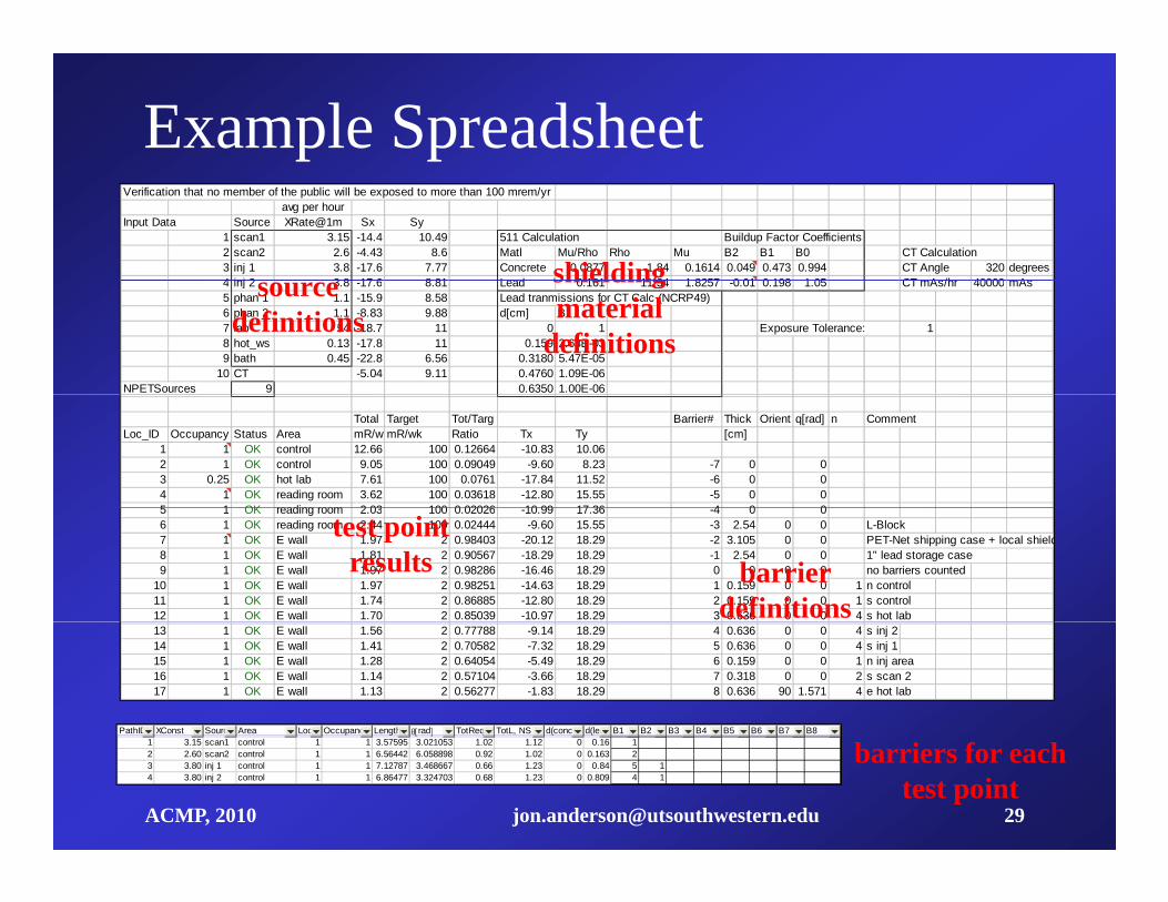
Example SpreadsheetVerification that no member of the public will be exposed to more than 100 mrem/yr
avg per hourInput Data Source XRate@1m Sx Sy
1 scan1 3.15 -14.4 10.49 511 Calculation Buildup Factor Coefficients2 scan2 2.6 -4.43 8.6 Matl Mu/Rho Rho Mu B2 B1 B0 CT Calculation3 inj 1 3.8 -17.6 7.77 Concrete 0.0877 1.84 0.1614 0.049 0.473 0.994 CT Angle 320 degrees4 inj 2 3 8 17 6 8 81 Lead 0 161 11 34 1 8257 0 01 0 198 1 05 CT mAs/hr 40000 mAsshielding4 inj 2 3.8 -17.6 8.81 Lead 0.161 11.34 1.8257 -0.01 0.198 1.05 CT mAs/hr 40000 mAs5 phan 1 1.1 -15.9 8.58 Lead tranmissions for CT Calc (NCRP49)6 phan 2 1.1 -8.83 9.88 d[cm] B7 lab 54 -18.7 11 0 1 Exposure Tolerance: 18 hot_ws 0.13 -17.8 11 0.159 2.63E-039 bath 0.45 -22.8 6.56 0.3180 5.47E-05
10 CT -5.04 9.11 0.4760 1.09E-06NPETSources 9 0.6350 1.00E-06
source definitions
shielding material
definitions
Total Target Tot/Targ Barrier# Thick Orient q[rad] n CommentLoc_ID Occupancy Status Area mR/wkmR/wk Ratio Tx Ty [cm]
1 1 OK control 12.66 100 0.12664 -10.83 10.062 1 OK control 9.05 100 0.09049 -9.60 8.23 -7 0 03 0.25 OK hot lab 7.61 100 0.0761 -17.84 11.52 -6 0 04 1 OK reading room 3.62 100 0.03618 -12.80 15.55 -5 0 05 1 OK reading room 2 03 100 0 02026 10 99 17 36 4 0 05 1 OK reading room 2.03 100 0.02026 -10.99 17.36 -4 0 06 1 OK reading room 2.44 100 0.02444 -9.60 15.55 -3 2.54 0 0 L-Block7 1 OK E wall 1.97 2 0.98403 -20.12 18.29 -2 3.105 0 0 PET-Net shipping case + local shield8 1 OK E wall 1.81 2 0.90567 -18.29 18.29 -1 2.54 0 0 1" lead storage case9 1 OK E wall 1.97 2 0.98286 -16.46 18.29 0 0 0 0 no barriers counted
10 1 OK E wall 1.97 2 0.98251 -14.63 18.29 1 0.159 0 0 1 n control11 1 OK E wall 1.74 2 0.86885 -12.80 18.29 2 0.159 0 0 1 s control12 1 OK E wall 1.70 2 0.85039 -10.97 18.29 3 0.636 0 0 4 s hot lab
barrier definitions
test point results
13 1 OK E wall 1.56 2 0.77788 -9.14 18.29 4 0.636 0 0 4 s inj 214 1 OK E wall 1.41 2 0.70582 -7.32 18.29 5 0.636 0 0 4 s inj 115 1 OK E wall 1.28 2 0.64054 -5.49 18.29 6 0.159 0 0 1 n inj area16 1 OK E wall 1.14 2 0.57104 -3.66 18.29 7 0.318 0 0 2 s scan 217 1 OK E wall 1.13 2 0.56277 -1.83 18.29 8 0.636 90 1.571 4 e hot lab
PathID XConst Source Area Loc_IDOccupancy Length rad TotReqL,WTotL, NS d(concret d(lead)B1 B2 B3 B4 B5 B6 B7 B8
ACMP, 2010 [email protected] 29
barriers for each test point
1 3.15 scan1 control 1 1 3.57595 3.021053 1.02 1.12 0 0.16 12 2.60 scan2 control 1 1 6.56442 6.058898 0.92 1.02 0 0.163 23 3.80 inj 1 control 1 1 7.12787 3.468667 0.66 1.23 0 0.84 5 14 3.80 inj 2 control 1 1 6.86477 3.324703 0.68 1.23 0 0.809 4 1
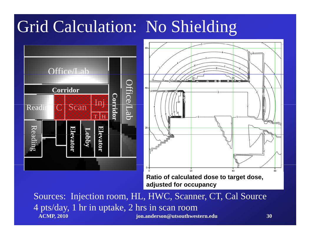
Grid Calculation: No Shielding
Office/Lab
S InjC
O ce/ ab
Corridor Cor
Office/
Scan InjCHT
Reading
rridor
Rea
/Lab
Ele
Ele
Loading
evator
evator
obby
So rces: Injection room HL HWC Scanner CT Cal So rceDoseToTargetRatio
Ratio of calculated dose to target dose, adjusted for occupancy
ACMP, 2010 [email protected] 30
Sources: Injection room, HL, HWC, Scanner, CT, Cal Source4 pts/day, 1 hr in uptake, 2 hrs in scan room

Grid Calculation: Shielded
Y image
DoseToTargetRatio
No shielding in walls in excess of 5/16" Pb; did require ceiling, floor
ACMP, 2010 [email protected] 31
No shielding in walls in excess of 5/16 Pb; did require ceiling, floor shielding. Was not necessary to run "box" to ceiling.

Grid Calculation: No Shielding
Office/LabOOPS's happen with complicated schemes: Both floor and ceiling
S InjC
O ce/ ab
Corridor Cor
Office/
schemes: Both floor and ceiling needed lead, installed as lead sheet bonded to plywood panels and held Scan InjC
HTReading
rridor
Rea
/Lab
Ele
Ele
Lo
p y pin brackets fastened to structural web, but different thickness above
d b l
ading
evator
evator
obbyand below.
The contractor switched them in
So rces: Injection room HL HWC Scanner CT Cal So rceDoseToTargetRatio
Ratio of calculated dose to target dose, adjusted for occupancy
The contractor switched them in spite of explicit drawings and clearly labeled leaded panels.
ACMP, 2010 [email protected] 32
Sources: Injection room, HL, HWC, Scanner, CT, Cal Source4 pts/day, 1 hr in uptake, 2 hrs in scan room
p
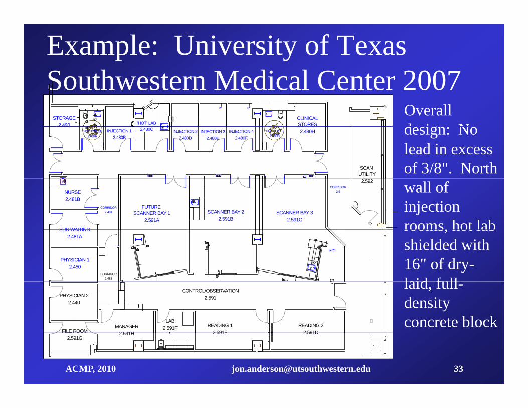
Example: University of Texas S th t M di l C t 2007Southwestern Medical Center 2007
STORAGE2.490
54"
54"
CLINICALSTORES'HOT' LAB
Overall d i N2.490
INJECTION 42.480F
2.480HINJECTION 32.480E
INJECTION 22.480D
'HOT' TOILET2.480A
SCAN UTILITY
'HOT' TOILET2.480G
INJECTION 12.480B
2.480C design: No lead in excess of 3/8". North
CORRIDOR2.481
CORRIDOR2.5
SCANNER BAY 32.591C
SCANNER BAY 22.591B
NURSE2.481B
SUB-WAITING
FUTURE SCANNER BAY 1
2.591A
2.592 wall of injection rooms, hot lab
CORRIDOR2.482
PHYSICIAN 12.450
SUB-WAITING2.481A
rooms, hot lab shielded with 16" of dry-laid f ll
MANAGER2 591H
READING 22 591D
READING 12 591E
PHYSICIAN 22.440
CONTROL/OBSERVATION2.591
FILE ROOM
LAB2.591F
laid, full-density concrete block
ACMP, 2010 [email protected] 33
2.591H 2.591D2.591E2.591G

Look Up, Down, and Sideways
ElectricalElectrical Elevator,Lobby
Duct penetrations in ceiling required separate shielding.
Corridor Corridor
Glass Wash
cal S
pace
Mechanical Space Mec
hani
c
Exterior
ACMP, 2010 [email protected] 34
Floor Plan Relative Dose Map on Floor Above
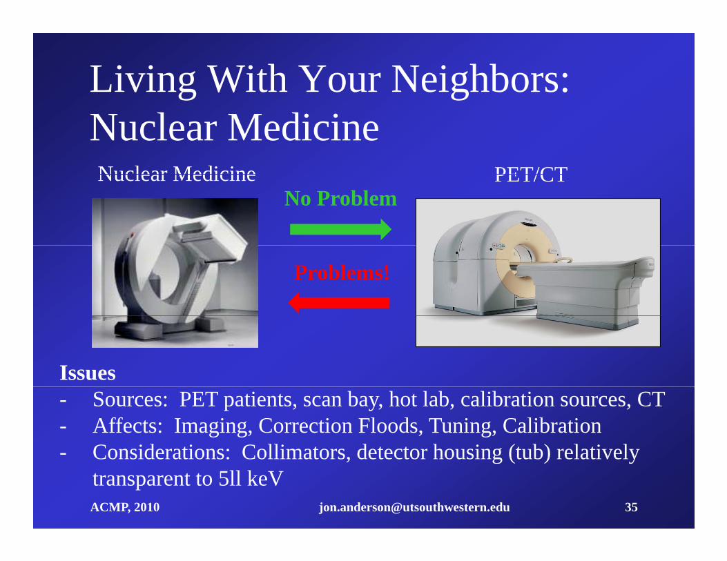
Living With Your Neighbors: Nuclear MedicineNuclear Medicine PET/CTNuclear Medicine PET/CT
No Problem
Problems!
Issues- Sources: PET patients, scan bay, hot lab, calibration sources, CT- Affects: Imaging, Correction Floods, Tuning, Calibration- Considerations: Collimators, detector housing (tub) relatively
ACMP, 2010 [email protected] 35
Considerations: Collimators, detector housing (tub) relatively transparent to 5ll keV
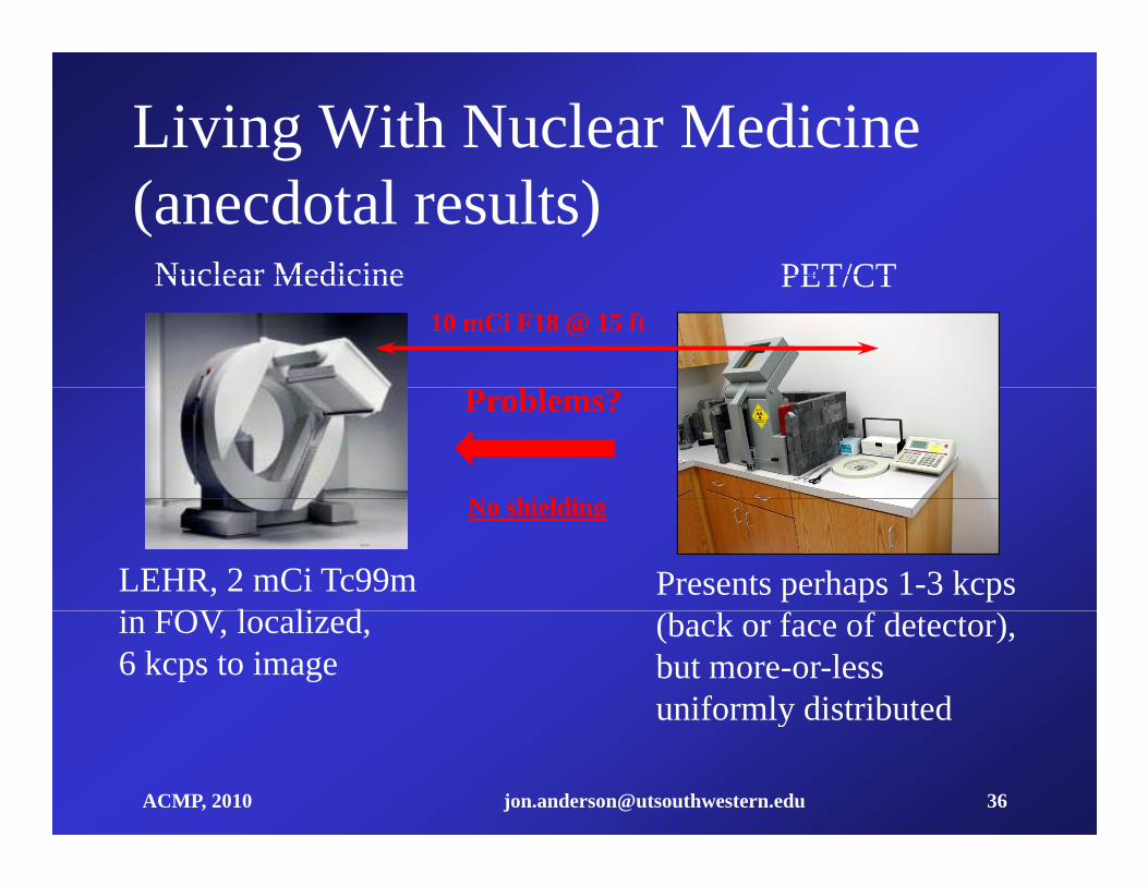
Living With Nuclear Medicine(anecdotal results)
Nuclear Medicine PET/CTNuclear Medicine PET/CT10 mCi F18 @ 15 ft
Problems?
N hi ldi
LEHR, 2 mCi Tc99m i FOV l li d
Presents perhaps 1-3 kcps
No shielding
in FOV, localized, 6 kcps to image
(back or face of detector), but more-or-less uniformly distributed
ACMP, 2010 [email protected] 36
y
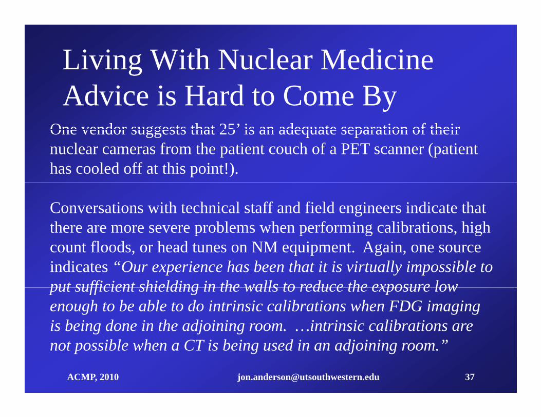
Living With Nuclear MedicineAdvice is Hard to Come By
One vendor suggests that 25’ is an adequate separation of theirOne vendor suggests that 25 is an adequate separation of their nuclear cameras from the patient couch of a PET scanner (patient has cooled off at this point!).
Conversations with technical staff and field engineers indicate that there are more severe problems when performing calibrations, high p p g , gcount floods, or head tunes on NM equipment. Again, one source indicates “Our experience has been that it is virtually impossible to put sufficient shielding in the walls to reduce the exposure lowput sufficient shielding in the walls to reduce the exposure low enough to be able to do intrinsic calibrations when FDG imaging is being done in the adjoining room. …intrinsic calibrations are
bl h CT b d d ”
ACMP, 2010 [email protected] 37
not possible when a CT is being used in an adjoining room.”

Living With Nuclear MedicineClosing Thoughts
S t N l M di i d PET id l iblSeparate Nuclear Medicine and PET as widely as possible.
NM imaging will be less affected than NM calibrations.
Shielding may be required, but we have no standards right now. It may be advantageous to extend the CT shielding above the normalmay be advantageous to extend the CT shielding above the normal 7’ level.
It b t h d l t f NM i (i t i iIt may be necessary to schedule some types of NM service (intrinsic calibrations, tunes, high count floods) at times when there will be no CT operations and no PET isotopes (patients, unshielded
ACMP, 2010 [email protected] 38
sources) in adjacent areas.
