pf osm 05-4-16 - astec, inc. · table table of introduc opera scop danger s dang basic how t war...
TRANSCRIPT

OPE
ASAGGR
ERATIO
STEC’S REGATE
F
Version
ON ANDASTEC
ECONOE DRYING
URY
n 2, 05/04/20
D SERVBurner Gr
OMICALG BURN
016
VICE Mroup
NER
MANUAAL

TableTable of
Introduc
Opera
Scop
Danger S
DANG
Basic
How t
WAR
General
Receiving
Burner C
Notes
Combust
Operatio
Adjustme
Burner D
Burner M
Burner P
Adjus
Natural
e of Conf Contents ....
ction .............
ation and Se
e of this Man
Safety and W
GER Combus
c Safety instr
to Recognize
NING! ..........
Burner Info
g and Inspe
Capacity ......Tab
s: For Table-
tion Flightin
on .................IlluIlluIllu
ents .............
Dimensions .
Mounting ....
Pilot SystemIlluIllu
stment and O
Gas Fuel PiIlluTabTabTabTabIllu
ntents ....................
....................
ervice Statem
nual ..............
Warnings ....
stion Equipm
ructions .......
e Shock .......
.....................
ormation .....
ection ...........
....................ble - 1 Burne
-1 ..................
ng ................
....................ustration 1a –ustration 1b –ustration 1c –
....................
....................
....................
...................ustration 2 - Pustration 3 –
Operation of
iping Systemustration 4 - Gble 2 - Feed ble 3 - Feed ble 4 - Recomble 5 - Naturustration 5 - R
....................
....................
ment ..............
.....................
....................
ment .............
.....................
.....................
.....................
....................
....................
....................er Capacities
.....................
....................
....................– Componen– Componen– Componen
....................
....................
....................
....................Pilot SystemTypical Pilo
the Pilot Sys
m……………Gas Train CPipe Size, foPipe Size, fommended Piral Gas ReguRegulator R
Phoenix
2
....................
....................
......................
......................
....................
......................
......................
......................
......................
....................
....................
....................s ..................
......................
....................
....................nt Identificatnt Identificatnt Identificat
....................
....................
....................
....................m ..................ot Gas Train
stem…………
………………omponents..or Gas Runs or Gas Runs ipe Nipple ...ulators ..........equirements
x FURY - O
....................
....................
.....................
.....................
....................
.....................
.....................
.....................
.....................
....................
....................
....................
....................
.....................
....................
....................tion and Loction and Loction and Loc
....................
....................
....................
....................
.......................................
…………………
…………….................... Over 25 Fe 25 Feet or U........................................s ...................
Operation and
....................
....................
.....................
.....................
....................
.....................
.....................
.....................
.....................
....................
....................
....................
....................
.....................
....................
....................cation ...........cation ...........cation………
....................
....................
....................
....................
....................
....................
………………
……………....................et ................Under ......................................................................
d Service M
....................
....................
......................
......................
....................
......................
......................
......................
......................
....................
....................
....................
....................
......................
....................
....................
....................
....................………………
....................
....................
....................
....................
....................
....................
…………………
………………........................................................................................................................
anual
...... 2
...... 4
....... 4
....... 4
...... 4
....... 4
....... 4
....... 5
....... 5
...... 5
...... 6
...... 6
...... 6
....... 6
...... 7
...... 7
...... 8
...... 8 ……9
........
...... 9
...... 9
.... 10
.... 10
.... 10
……11
…..12 .... 12 .... 13 .... 13 .... 13 .... 13 .... 14

Fuel Oil
Heavy O
Propane
Introd
Liqui
Liqui
Fuel Oil
To Re
To Re
Flame Sh
Flame Sc
Flame Sc
Mainten
Maint
Troub
Recomm
Detailed
Altitude High Alt
V-Belt T
Piping SystTabTabIlluIllu
Oil Fuel PipinIlluIllu
Fuel System
duction ........
d Propane fuIlluTab
d Propane syIllu
Atomizer ....Illu
eset the Nozz
emove the O
hape Adjust
canner ........Illu
canner Cool
ance & Trou
tenance Sch
ble Shooting
mended SpareTabTab
Burner Perf
Correction Ctitude Blowe
IllustrIllustrIllustrIllustrIllustrIllustr
Tensioning Illustr
tem ..............ble 6 – Fuel ble 7 – Minimustration 6 - #ustration 7 - #
ng System ...ustration 8 - Hustration 9 –
m .................
.....................
uel pump sysustration 10 –ble 8 – Liqui
ystem startuustration 11 –
....................ustration 12 –
zle Position,
Oil Gun Assem
tments .........
....................ustration 13 -
ling Air .......
uble Shootin
edule ...........
g ....................
e Parts ........ble 9 – Spareble 10 – Noz
rformance S
Chart ..........er Kit Additiration 14a - Bration 14b - Bration 15 - Bration 16 - Bration 17 - Bration 18 - B
ration 19 – V
....................Oil Train Semum Oil Lin#2 Fuel Oil T#2 Fuel Oil P
....................Heavy Fuel Heavy Fuel
....................
.....................
stem .............– Liquid Proid Propane T
up procedure– Liquid Pro
....................– PF Nozzle
use the follo
mbly, use the
....................
....................- Flame Scan
....................
ng Guide .....
.....................
.....................
....................e Parts List ..zzle Spare Pa
Sheets ...........
....................ion Burner HighBurner High
Burner High ABurner High ABurner High ABurner High A
V-Belt Tensi
Phoenix
3
....................ettings ..........ne Size for vTrain ...........Piping Schem
....................Oil Train ....Oil Piping S
....................
......................
......................opane Fuel TTrain Setting
e ....................opane Piping
....................Settings .....
owing steps
e following s
....................
....................nner .............
....................
....................
......................
......................
....................
....................arts List .......
....................
....................
h Altitude Blh Altitude BlAltitude BloAltitude BloAltitude BloAltitude Blo
oning Detail
x FURY - O
....................
....................various lengt....................matic ..........
....................
....................Schematic ...
....................
.....................
.....................Train ............gs .................
.....................g Schematic .
....................
....................
: ...................
steps: ..........
....................
....................
....................
....................
....................
.....................
.....................
....................
....................
....................
....................
....................
lower Kit Adlower Kit Adower Kit Addower Kit Addower Kit Addower Kit Add
l……………
Operation and
....................
....................ths .......................................................
....................
....................
....................
....................
.....................
.............................................................
.........................................
....................
....................
.....................
.....................
....................
....................
....................
....................
....................
.....................
.....................
....................
....................
....................
....................
....................
ddition ……ddition ……dition ………dition ………dition ………dition ………
………………
d Service M
....................
....................
....................
....................
....................
....................
....................
....................
....................
......................
......................
....................
....................
......................
....................
....................
....................
......................
......................
....................
....................
....................
....................
....................
......................
......................
....................
....................
....................
....................
....................
…...…..……..…….………
………….....………….....…...………………...………
……………...
anual
.... 15
.... 15
.... 15
.... 16
.... 16
.... 17
.... 17
.. 167
.... 20
..... 20
..... 20
.... 20
.... 20
..... 21
.... 21
.... 22
.... 22
..... 22
..... 22
.... 23
.... 23
.... 24
.... 24
.... 25
..... 25
..... 26
.. 278
.. 278
.. 278
.. 289
.... 30
.....31 …..31 .....32 .....32
…..33 …..34
....35

Introd Operati These insmaintenancompletenpossibilitycontact AS Scope o The objecBurner Sycontrolling
Dang DANGE OperatingPhoenix F Basic S 1. Alway2. Equip
other 3. Keep
chain4. Use e5. Check6. All the
equip7. Prior t8. Never9. Make
repres10. Accou11. Avoid
in rota12. Never13. To av
the co14. Never
progra15. Reliev16. Caref17. Thoro
duction
on and Se
structions are nce of ASTECness, unforesy. If there is anSTEC Burner
of this Man
ctives of this mystems Groupg quality and
ger Safe
ER Combus
g this Burner oFURY safety d
Safety instr
ys lockout powpment that is d
potential eneaway from poed down.
extreme cautiok that all fuel e drive guardsment. to start up chr remove, dis no modificatsentative of Aunt for all you wearing loosating machiner leave the co
void engulfmeold feed bins. r enter a poteam in effect. (ve internal prefully vent any oughly tighten
n
rvice State
intended to sC Burner Groseen or unspeny informationr Group for cla
nual
manual are top equipment. compliance to
ety and
stion Equip
outside its dedevice can ca
ructions
wer to any plade-energized ergy sources. ower driven p
on if you mussources are ss, handrails, a
eck that all plable, defeat, ions to your P
ASTEC Burner personnel, o
se clothing, loery. ontrol house uent by loose a
entially hazard(Contact ASTessure beforeflammable ga
n all fittings be
ement
serve as guideup equipmen
ecified applican that is unclearification bef
o document thIt provides p
o requiremen
Warni
pment
sign parametause an explo
ant equipmencan still retai
parts, even if t
st approach rushut off, and land other saf
lant componeor bypass an
Phoenix FURYer Group, Engon the jobsite
ong hair, neck
unattended, wggregate, nev
dous enclosedTEC Parts Dee working on aas using safeefore reapplyi
Phoenix
4
elines coverint. While ever
ations, detailsear, contradicfore proceedi
he installationolicies, procets.
ngs
ters, and/or reosion, serious
nt before workn residual en
they are not m
unning equipmlocked out priety devices m
ents are in gooy safety devicY Burner with
gineering or Se, before plantklaces, necktie
while the plantver walk on th
d space, withpartment for aany equipmety measures ng pressure.
x FURY - O
ng the installary attempt has, or variationsctory, or abseng.
, operation, aedures and re
emoving, disas injury, or dea
king on it. nergy, or may
moving, unles
ment. ior to working
must be in pla
od working coce on this equhout the recomService Depar
t startup. es, or anythin
t is in operatiohe material st
out an OSHAan outline of nt containing that will preve
Operation and
ation, operatios been mades may precludnt from this m
and maintenaeferences for a
abling, or bypaath.
be susceptib
ss they are lo
g on the burneace before sta
ondition. uipment. mmendation ortments.
ng that could
on. tockpiles, or o
A enclosed spthese requirehigh pressur
ent ignition.
d Service M
on, and e to ensure de covering e
manual, pleas
nce of ASTECassuring and
assing any
ble to gravity o
cked out or
er. arting the
or approval of
become enta
on the materia
pace permit ements.) re.
anual
every e
C
or
f a
angled
al in

How to Shock is A rap Rapid A feel Confu Pale,
First aid f Have Eleva Cover Trans WARNIN Carefullywarning m Alway To pre
comp Never
(Apprspecif
Theseperso
Gene The Phoepollution. aggregate
The Phoecombustiooperation
The Fuel/electronicand liquid
The burneoperation
Recognize
caused by aid and weak p
d breathing. ling of tiredneused thinking.cold, and sw
for shock: the victim lie
ate the victim’sr the victim w
sport the victim
NG!
y read the safmessages loys lock-out poevent seriousonents removr repair this broved parts arfically approve instructions onnel are thos
eral Burenix FURY buWith its comp
e.
enix FURY Buon air. This eat maximum
Air ratio is macally linked va propane dep
er provides a at various pr
e Shock
a rapid loss opulse.
ess, or sleepin. eaty skin.
down, and res feet, to imprith a blanket tm to a hospita
fety instructiocated througower before ws bodily injuryved. urner with repre only those ved by the AS
are intendedse trained by A
rner Infrner is design
pact flame sh
urner has an oensures that th
capacities.
aintained throlves. The Ph
pending on yo
nominal 7:1 toduction rate
of blood pres
ness.
emain quiet. rove circulatioto maintain boal, medical cli
ions in this oghout this m
working on any, do not opera
placement paavailable throTEC Burner S for use only ASTEC Burne
formationed to provideape, the Phoe
open fired comhe combustio
oughout the bhoenix FURYour configurat
turndown fromes.
Phoenix
5
ssure, the sy
on to the headody temperatnic, or doctor
operating anmanual.
y plant equipmate any plant
arts not approough ASTEC Systems Grouby experiencer Systems G
on e maximum fienix FURY fla
mbustion syston air, plus 25
urner's operawill burn all c
tion.
m its maximum
x FURY - O
ymptoms inc
d and chest.ture. r’s office as so
d service ma
ment. equipment w
oved by the mparts departmup.)
ced and qualifGroup, or AST
iring capabilityame provides
tem that prov5% excess air
ating range wicommercial gr
m firing rate.
Operation and
clude:
oon as possib
anual. Follow
with the guard
manufacturer. ment, or any o
fied personneTEC’s Service
ty with minimus the ideal me
vides 60% of ar, is available
ith either mecrades of fuel o
This provides
d Service M
ble.
w all the safe
s or other saf
other parts
el. (Qualified e Department
um noise andeans for dryin
all the necessfor efficient
chanically or oil, natural ga
s efficient
anual
ety
fety
t.)
d g
sary
as,

BURNERMODEL
PF-25
PF-35
PF-50
PF-75
PF-100
Rece Upon rece 1. Check
shipp2. Caref
any d3. If ther
(423-8
NOTE: If the insta1. Provid2. Speci
from r3. Also i
aroun
Burn
Notes: F 1. The m2. The fi
70F a3. Corre
Chart4. Visco5. The s
0.25" preve
6. The a(The b
7. Gas bflow r
8. The von the
RBURAIR F
SC
192,
269,
379,
590,
725,
eiving a
eipt of the Bu
k each item oed has been fully examine amage in shire are any da867-4210, or
allation is delade adequate ial care shoulrain, snow, ornspect the pi
nd it is uniform
er Capa
For Table-
maximum BTUgures used in
air temperaturection factors t.) sity of the oil
system exhauwater column
ent “puffing” atair flow in the body pressurburners are suate measured
values of diffee plant’s flash
NERFLOW
FH
BB
,000
,000
,000
,000
,000
nd Insp
rner:
on the bill of lareceived. all of the equpment. maged or misFAX 423-827
ayed and the protection, asd be given tor excessive mntle at the en
m.
acity
1
U/hour rating n Table – 1 arre, at sea levemust be appl
delivered to tst fan must hn) at the burnt the breechinPhoenix FURe for a given upplied with ad in inches of rential pressu
h drive.
BURNERBLOWER
HP
30
40
50
75
100
pection
ading and/or i
uipment, asse
ssing parts, co7-1560)
equipment iss dictated by y all; motors, h
moisture. d of fuel oil no
Table - 1 B
is based on 2re based on: el. ied for altitud
the burner muave enough cer breech pla
ng plate.) RY can be moflow is in the
a metering oriwater column
ure versus flo
Phoenix
6
NATURAGAS
SCFH
25,000
35,000
50,000
75,000
100,00
n
nvoice to det
emblies and s
ontact ASTEC
s to be storedyour climate ahydraulics, ele
ozzle and ens
Burner Capa
25% excess a 60Hz AC, an
e or temperat
ust be 80 SSUcapacity to prate. (This will
onitored usingindividual burfice plate. Thn with a differw are listed in
x FURY - O
AL
H
OFLG
0 2
0 4
0 5
0 8
00 1
termine that a
ub-assemblie
C Service or
outside: and the perioectrical parts,
sure that it is
acities
air. nd Standard C
ture variation
U (maximum)rovide a slightexhaust the p
g the pressurerner capacity his creates a rential pressun the individu
Operation and
OILLOWGPM
2.9
4.1
5.9
8.8
1.7
all the equipm
es to check if
Burner Group
d of exposure, and bearing
not bent and
Cubic Feet pe
ns. (See Altitu
) or lower. t negative preproducts of co
e tap in front otables.) differential pr
ure gauge, or ual burner cap
d Service M
MAXIMCAPACBTU/HO
25,000,
35,000,
50,000,
75,000,
100,000
ment that was
there has bee
p for assistan
e. s, to protect t
the gap all
er Hour (SCF
de Correction
essure (0.15” ombustion, an
of the dampe
ressure at a gmanometer.
pacity sheets
anual
UMCITYOUR
,000
,000
,000
,000
0,000
en
ce.
them
H), at
n
to nd
r.
given
found

Comb 1. The fl
pollut2. The fl
skin fr3. For th
of veicomb
4. The cdiameBurne
5. The c(A goflow ucool t
6. The A
Oper 1. The b
damp2. The P
sophimanip
3. The P4. A com
This p5. The c
a. Tb. T
usc. Td. T
pue. T
ch5. Befor6. The lo
positio7. The lo
closed
bustion
ight design inant emissionsights providerom the flamehe lowest posling material. ustion.)
combustion zoeter of the comer Performanccombustion fligod combustio
under them nehe flights.)
ASTEC Parts
ation basic model Pper which is mProgrammablestication to thpulates the fuPLC allows thmbustion blowpressure switccombustion aihe safety limihe purge pressually set at 1he plant flue he fan dampeurge time. he minimum hamber e light-off theow-fire combuon. ow fire proof fd with the low
n Flight
n the combusts. heat shieldin
e radiating dirsible emissio (Showering
one must be lmbustion zonce Data Sheeghts are desig
on flight desigext to the she
Department c
Phoenix FURYmechanically lie Logic Contr
he managemeel valve posite fuel and air
wer pressure sch is usually sr control damit parameters ssure switch 10” w.c. gas exhaust fer must be op
purge time is
combustion austion air dam
fuel valve limiw fire combust
ting
tion zone of t
ng to keep therectly onto thens of CO andmaterial throu
arge enough e must be lar
ets for the flamgned to be sen plows most
ell, insulating t
can supply co
Y uses a firinginked to the furol (PLC) optioent of the fueltion. r valve to be cswitch (normaset at 1.5” w.c
mper must opemust be satis
must be tripp
fan must be cpen enough fo
the time requ
air damper mmper limit swit
it switch (the tion air switch
Phoenix
7
he drum is es
e drum skin tee drum.) d Total Hydrocugh the flame
to accommodrge enough fome dimensionelf-cooling, to t of the materthe drum from
ombustion flig
g rate control uel valves anon for the bur/air ratio by a
controlled indeally open) muc. en to initiate thsfied. ed for the pur
confirmed to bor the calculat
uired for four
must be at the tch is set to c
switch that coh for the light-
x FURY - O
specially impo
emperature lo
carbons, the e is a commo
date completeor the burner ns.)
prevent theirrial over the flm radiant heat
ghts designed
motor mountd air damperrner control p
adding anothe
ependently. ust be made to
he purge cyc
rge cycle to b
be running. ted volume o
volumes of a
low-fire positlose its conta
ontacts the fu-off sequence
Operation and
ortant for min
ow. (Protectin
combustion zn cause of inc
e combustionflame to fit in
r failure throulights, while at, and using t
d for your app
ted to the com. rovides addit
er control mot
o prove the b
le prior to ligh
begin. This p
of air to flow d
ir to flow thro
tion. acts at the min
uel valve linkae to begin
d Service M
imizing flue g
g the metal d
zone must be complete
n. (The lengthside. See th
gh overheatinallowing somehe aggregate
plication.
mbustion air
ional tor that
lower is oper
hting the burn
ressure switc
uring the requ
ough the heati
nimum fire lig
age arm) mus
anual
gas
drum
clear
h and he
ng. e to e to
rating.
ner.
ch is
uired
ing
ht off
st be

I
I
Illustration 1
Illustration 1
1a – Compo
1b – Compo
Phoenix
8
nent Identifi
nent Identifi
x FURY - O
fication and L
fication and L
Operation and
Location
Location
d Service Manual

Burn Phoenix Flocated pl
Burn 1. The c
the dr2. The in3. Cut o4. Check
I
er DimeFURY dimensease contact
er Mou
centerline of thrum. nsertion depthut a hole in thk burner blow
Illustration 1
ensionssion drawings
Astec Burne
nting
he Burner sho
h should be she breeching wer rotation. R
1c – Compo
s are located or Group.
ould be moun
such that the eplate 3" smal
Rotation shou
Phoenix
9
nent Identifi
on the plant’s
nted on the ce
end of the buler in diameteld be clockwis
x FURY - O
fication and L
s flash drive. I
enterline of th
rner is 2 or 3”er than the buse from the m
Operation and
Location
f the drawing
he drum, at th
” behind the burner radiationmotor end.
d Service M
gs cannot be
e same pitch
breaching ringn shield.
anual
as
g.

Burn The Phoea single Upackage. pressure.
er Pilotenix FURY incUltra Violet (U
The air for th The adjustm
t Systecorporates a fV) flame detehe pilot is pro
ment and oper
Illus
m
forced-air piloector attachedvided from inration of the p
Illustratio
stration 3 –
Phoenix
10
ot system. Thd to the burneside the fan h
pilot system is
on 2 - Pilot S
Typical Pilo
x FURY - O
he Pilot and ther, and includehousing whers detailed belo
System
ot Gas Train
Operation and
he main flameed in the comre there is a cow.
n
d Service M
e are monitormplete burner constant air
anual
ed by

Adjustm 1. Use N
WAR
2. If natupiping
3. If yougas fe
4. Purge5. Size t
50 fee6. Gas p7. The e
union8. Remo
socke9. Make10. Remo
for les11. The in
Propa12. At this
WAR
ment and O
Natural Gas (NNING!
Never consent to theburner.
ural gas is theg, upstream o will be firing eed piping to e the fuel pipinthe pilot gas set long, use apressures at tentire pilot asss along the s
ove the spark et. sure the spa
ove the protecss gas pressunitial recommane, 2”-3” Was rate the piloNING!
The pilot igOnly leaveIf pilot doe
Operation o
NG) or Liquid
nect the LP fue pilot, where
e primary fuelof the main co
using liquid fua LP vapor linng of any consupply line to a minimum of he inlet of thesembly can beide of the burplug wire boo
ark igniter is coctive cover onure, Turn counended fuel pr
ater Column foot should light
gnition transfoe the pilot gases not light at
of the Pilot
Propane (LP
uel line to theit could quick
, the pilot fueontrol regulatouels, and/or nne. (See abovntaminates beavoid an exc3/8" pipe.)
e gas pilot mae removed frorner, then pullot; then the s
onnected to tn the adjustabnter-clockwiseressure settinor Natural Gat the main bur
ormer can caus on for a veryonce, shut it o
Phoenix
11
t System
P) vapor only
e pilot from thekly boil off, ca
el supply shouor. natural gas seve warning.)efore connectcessive pressu
anifold can raom the burneling the assempark plug can
he ignition trable pilot gas oe to increase g is approxim
as measured arner easily, an
use a painful y short periodoff, and then
x FURY - O
to fuel the pil
e bottom of thusing either a
uld be connec
ervice is not c
ting it to the pure drop. (Fo
nge from 8 toer by removingmbly backwarn be removed
ansformer. orifice; rotate t
the gas presmately 2”-3” Wat the test pond deliver a s
shock, use cd of time while
purge it befor
Operation and
ot.
he LP tank. Lan explosion o
cted to the na
currently avail
ilot assemblyr a pilot gas s
o 25 psig. g the strut bords.
d with a stand
the adjustmessure Water Column
rt. Air pressursufficient UV f
care around the lighting the bre attempting
d Service M
P would likelyor fire in the
tural gas feed
lable, connec
y. supply line up
lts and pipe
ard spark plu
nt screw cloc
n for Vaporizere not adjustaflame signal.
he ignition cabburner.
g to relight.
anual
y be
d
ct the
p to
ug
ckwise
ed able.
ble.

Natur
Gas T 1. Instal
a. Tb. 3
shB
c. Esi
2. The ppress
3. The pentran
NOTE: It is norma NOTE: If the Gas
ral Gas
Train Cl a controllinghis regulator – 5 psig is th
heet found onurner Performxact gas presize, and maxi
piping from theure losses.
pipe size fromnce to the bur
al for the regu
s run is more t
s Fuel P
Il
Compong gas regulatoshould be siz
he nominal exn the plant flamance Sheetsssure must bemum rated cae gas regulato
the control rerner gas train
ulator size to
than 25’, use
Piping S
llustration 4
nents or in the main zed to providexpected gas psh drive for ms) e set at the inapacity. or outlet to th
egulator to th, see tables b
be smaller th
the connectio
Phoenix
12
System
4 – Natural G
gas line withe the requiredressure requi
more precise b
itial start-up d
e burner gas
e gas train, cbelow.
an the line siz
on size on the
x FURY - O
Gas Train
in 25 feet of td gas flow at tired at the buburner specifi
depending on
manifold sho
can be identic
ze.
e burner show
Operation and
the burner. the inlet of theurner refer to tic information
n piping config
ould be sized
cal to the gas
wn in Table 2
d Service M
e burner manthe burner pro
n. ( See Detai
guration, burn
to minimize
pipe size at th
below.
anual
ifold. ofile led
ner
he

B
(M
B
(M
Burner ModelPipe Size
Minimum Dia.
Burner ModelPipe Size
Minimum Dia.
Burner ModeASTEC
Part Number
Burner ModeMaximumCapacityGas InletPressureGas InletPipe Size
NOTE: If the Gas
4. The s
receiva. Sb. Tc. T
5. The grespo
NOTE: Install theproduced
NOTE: The low agas inlet pwould be pressure f
PF-
)4"
PF-
)4"
F
el PF
r076
AST
el PF25
Cu
2.5
4
s run is 25 fee
T
supplied manuved as a ship hutoff valve fhe strainer prhe Siemens d
gas company onsible for run
e flexible metaby plant vibra
and high gas ppressures res50% of the rufor the high g
-25
"
FEED PIPE
-25
"
FEED PIPE S
-25
046
TEC PART NU
F-25,000Ft/Hr
5 PSI
4"
NATURA
Table 2 - F
et or less. Use
Table 3 - Fee
ual shutoff valoose item.
facilitates servrotects the vadouble block should purge
nning the gas
al hose suppliations.
Ta
pressure switspectively. Thunning pressuas pressure s
T
PF-35
4"
E SIZE, FOR
PF-35
4"
SIZE, FOR GA
PF-35
076046
UMBERS, FL
PF-3535,000
Cu Ft/Hr
5.5 PSI
4"
AL GAS REG
Feed Pipe Si
e the connect
ed Pipe Size
lve, must be
vicing of the galves from desgas valve has
e the main gaslines from the
ed with the b
able 4 - Reco
ches should bis should be iure for the lowswitch.
Table 5 - Nat
Phoenix
13
PF-5
4"
GAS RUNS
PF-5
4"
AS RUNS 25
PF-
0760
LEXIBLE MET
PF-50,0
Cu F
5.8
4
GULATOR RE
ize, for Gas R
ion size on th
e, for Gas Ru
installed upst
gas train. structive dirt ts an integral ss line for scale gas meter to
urner gas ma
ommended P
be set just abindividually dew gas pressur
tural Gas Re
x FURY - O
50
"
OVER 25 FE
50
"
FEET OR UN
50
046
TAL BRAIDED
-50000Ft/Hr
PSI
4"
QUIREMENT
Runs Over 2
he burner sho
uns 25 Feet o
tream of the g
that could lodstrainer at thee and dirt, aso the plant ne
anifold to redu
Pipe Nipple
bove and beloetermined onre switch and
egulators
Operation and
PF-75
6"
EET
PF-75
4"
NDER
PF-75
048292
D HOSSE
PF-7575,000
Cu Ft/Hr
4.5 PSI
6"
TS
25 Feet
own in Table-3
or Under
gas safety val
ge in them. e inlet side of s well as the ceed to purge
uce flexing of
ow the safe op each installa 125% of the
d Service M
PF-1
6"
PF-1
4"
PF-1
0482
PF-1100,0Cu Ft
4.5 P
6"
3 below.
lve, if it was
the valve. contractor the lines.
the manifold
perating rangation. Typicall
operating
anual
00
00
00
92
00000/Hr
PSI
e of y this

6. The g7. See in
Sheet8. Use th WARNING
T F B
a 9. Meter
pre-pi T
P
gas valve linkandividual burnts) he utmost car
G! he settings ininal settings we sure not to dangerously
ring natural gaiped gas trainhe gas flows erformance S
Illus
age must be aner performan
re in making a
n Table 5 are will have to behave more furich firing con
as is accompn. versus orifice
Sheets.
stration 5 - R
adjusted for pnce sheets fo
any adjustme
for the regulae adjusted foruel flow than tndition could
lished by taki
e plate differe
Phoenix
14
Regulator Re
proper flow cor air and gas
ent to prevent
ator sizing onlr the particulathere is comboccur.
ng a different
ntial pressure
x FURY - O
equirements
ontrol. flows. (See D
an unsafe co
ly. ar operating cbustion air ava
tial pressure a
es are shown
Operation and
s
Detailed Burn
ondition.
conditions. ailable to burn
across the or
in the Detaile
d Service M
er Performan
n, or "puffing"
rifice plate in t
ed Burner
anual
nce
", and
the

Burner MPF-25PF-35PF-50PF-75PF-10
Burner MMaximuCapaci
LF Oil InPressu
Fuel * New D
1. For re2. Befor
could 3. Adjus
achiev4. Depe
desire5. The lo6. Leak 7. The m
burne8. The h
contro9. Oil flo10. Oil flo WARNING
T F B
a
Model 0550500
Modelumity
2
nleture
Oil Pip
Design, Refer
ecommendede attaching thclog and dam
st the pressureved. (See thending on the ed burner outow oil pressurtest the pipin
manual low firer. (See the Inhigh fire oil flool system. (Seow rates can bow rates can b
G! he settings arinal settings we sure not to dangerously
0' to 25'1/2"1/2"1/2"1"1"
Supply Li
PF-25
2.9 GPM
* PSI
ing Sys
r to Burner P
T
Table 7 – M
pipe sizes, she fuel lines, pmage the fuele control valve Individual Bsystem desigput. re switch is fag before start
re bypass oil cndividual Burw can be set ee the Individbe checked wbe confirmed
re for the initiwill have to behave more furich firing con
26' to 501/2"1/2"1/2"1"1"
ine In Feet, #2
FUEL
PF-35
4.1 GPM
50 PSI
FUEL O
stem
Profile Sheet
Table 6 – Fu
Minimum Oi
see Table 7. purge the pip system.
ve (located at Burner Performgn, the final pu
actory set at 3t-up, then checontrol valve ner Performaby varying thual Burner Pe
with the inline using the noz
al set-up onlye adjusted foruel flow than tndition could
Phoenix
15
0' 51
1
2 and Heavy o
L OIL LINE SIZ
P
M 5.9
1
IL TRAIN SET
ts
uel Oil Train
il Line Size f
ing to remove
the fuel pumpmance Data Sump pressure
30 PSIG. eck for leaks dis used to set
ance Data Shehe fuel pressuerformance Doil flow meterzzle pressure
y. r the particulathere is comboccur.
x FURY - O
' to 100'3/4"3/4"3/4"1"
1-1/4"
oil
ZES
PF-50
9 GPM
00 PSI
TTINGS
n Settings
for various l
e scale, dirt, a
p skid) until thSheets for thee will have to
daily. t and maintaieets for the loure, or by chaData Sheets for in the fuel co
e and the burn
ar operating cbustion air ava
Operation and
0' to 50'1/2"1/2"1/2"1/2"1/2"
Recircula
PF-75
8.8 GPM
88 PSI
lengths
and other con
he required oe approximatebe adjusted t
n the low fire ow fire oil settnging the valvor proper fuelontrol valve trner performan
conditions. ailable to burn
d Service M
51' t11111
ation Line In FHeavy Oil
PF
11.7
108
ntaminates tha
oil pressure is e settings.) to attain the
oil flow at theting.) ve profile in tl flows.) rain. nce data shee
n or "puffing”
anual
to 100'1/2"1/2"1/2"1/2"1/2"
Feet,
F-100
7 GPM
8 PSI
at
e
he
et.
and

I
Illustra
Illustration 6
ation 7 – #2
Phoenix
16
6 – #2 Fuel O
Fuel Oil Pip
x FURY - O
Oil Train
ping Schema
Operation and
atic
d Service Manual

Heav
WARNINGBe very ca
H D C
vy Oil FuG! areful with He
Heavy oil has tDo not heat theContact with th
uel Pip
eavy oil: to be heated e Heavy oil hhe hot oil, or p
Illu
Illustrati
ing Sys
to lower its viigher than its piping, can ca
ustration 8 –
ion 9 - Heav
Phoenix
17
stem
iscosity for prvapor point.
ause a severe
– Heavy Fue
vy Fuel Oil P
x FURY - O
roper atomiza
e burns.
el Oil Train
Piping Schem
Operation and
ation.
matic
d Service Manual

1. Also r2. For re3. Your 4. Prope
NOTEa. Tb. Cc. F
hd. Ne. T
thf. Mg. Th. Vi. Tj. S
thk. T
an5. Purge6. Adjus7. See th
Perfo8. Final
desig9. High f
individ10. The m
burne11. The lo12. The h WARNING
F B
da
referred to asecommendedburner shoulder fuel viscosi
E: Every shiphe viscosity o
Check the fuelor better comigher oil temp
Never heat thehe oil temper
he particular oMake sure the
hese vapor pVapor pockets
hey can evenet the oil hea
he burner’s oihis will prevend will prevene the lines befst the pressurehe individual rmance Data pump pressun. fire oil flow cadual burner pmanual low firer. Refer to indow oil pressurhigh oil pressu
G! inal settings we sure not to angerously ric
Recycled Fu pipe size seed fire on all coty is required
pment of oil mof the oil must specification
mbustion the vperature. e oil above 22rature switch moil being usedfuel is not forockets can ca can also inte
n cause pipester temperatul manifold) to nt the burner nt damage to fore attachinge relief valve burner perforSheets for prre will have to
an be set by aerformance s
re bypass oil cdividual burnere switch is faure switch is f
will have to behave more fuch firing cond
uel Oil (RFO).e Table 7. ommercially a for satisfacto
must be individt be 80 SSU (
ns to check thviscosity can b
20º F or 10º Fmust be adjus
d. rming vapor (ause the pumerrupt fuel flows to burst causure regulator, the temperatfrom operatinyour plant.
g them to the until the requ
rmance sheetroper fuel flowo be adjusted
adjusting fuel sheets. (See Bcontrol valve er performancactory set at 3factory set at
e adjusted foruel flow than tdition could oc
Phoenix
18
available heavory atomizatio
dually tested.(Saybolt Sece vapor pointbe lower than
below the vasted to the m
(steam) pockemp to cavitate,w causing thesing damage and the indic
ture determinng when the o
fuel manifolduired oil pressts for approximws.) d to obtain the
pressure or bBurner Perforis used to setce sheets. (Se30 PSIG. 150 PSIG.
r the particulathere is combccur.
x FURY - O
vy fuel oils. on and combu
conds, Univert of the fuel. n the 80 SSU
apor point of tinimum temp
ets in the oil l, causing dame burner to faland possible
cating low oil tned in item 3aoil is too thick
. sure is attainemate valve se
e rated burne
by re-strokingrmance Data t and maintaiee Burner Pe
ar operating cbustion air ava
Operation and
ustion of heav
rsal) or lowe
maximum, w
the fuel, whicperature for go
ines. mage to it. lter.
e injury. temperature s
a above. k to be atomiz
ed. ettings. (See
r output, depe
g the oil valveSheets) n the low fire
erformance D
conditions. ailable or "puf
d Service M
vy oil.
r.
which means a
hever is loweood atomizati
switch (locate
zed and burn
Burner
ending on sys
. Refer to
oil flow at theata Sheets)
ffing" and a
anual
a
er. on for
ed on
well,
stem
e

Burner
MaxiCap
Liquid ProPres
Line siz
Line size
Propa
Introduct
Propane idifferent fofor the preatomizatiodifferent soption.
On the othrelatively vaporizersdemands.2,500 Btu
Liquid Pr
LP fuel Puby Blackmof 225psidpressure mesh Y-ssand, rust
NOTE: Asrated safeswitch mucompliant
r Model
imumacityopane Inlet ssureze 0'-50'
e 51'-100'
ane Fuetion
s a common orms, liquid (essure rating on. Typical LPset of compon
her hand the lower pressus and thus the. The approxi/ Cu. Ft.
ropane fuel p
umps are ratemer and is rated. This pressuis 120psi the trainer in the t, pipe scale e
stec recommeety shut-off vaust be interloct as shown in
PF-25
4.5 GPM
TBD
3/4" NPT
1" NPT
el
fuel option in LP) and vapoof all the pipi
P pressure renents compar
VP (Vaporizere fuel rangine customer ismate heating
pump system
ed by the diffeed at a maximure is in additpressure prosuction side o
etc. which wil
ends the use alves piped incked with the illustration 10
Illustratio
Tab
PF-3
6.4 G
TB
3/4" N
1" N
LIQUID PROP
many countror (VP). The Lng and fittingquired at the
red to #2 or #6
ed Propane) fg anywhere b
s responsible value of Pro
m
erential pressmum working tion to the vapduced by the of the pump tl reduce the p
of LP fuel tra series in the burner’s safe0 below.
on 10 –Liqui
le 8 –Liquid
Phoenix
19 35
GPM
D
NPT
PT 1
PANE TRAIN S
ries besides #LP fuel train iss to handle thburner LP tra6 fuel trains. A
fuel train is simbetween 2 to to supply the pane in liquid
ure they can pressure of 2
por pressure oLP pump wil
to protect the pump life dras
ins that meetburner main
ety shut-off va
id Propane P
d Propane Tr
x FURY - O
PF-50
9 GPM
195 PSI
1" NPT
1/4" NPT
SETTINGS
#2 or RFO fues similar to a #he high pressain inlet is fromAstec offers L
milar to a natu5 psig. Astec VP at the pre
d form is 91,66
produce. The200psi differeof the LP tankl be 320psi. Itpump from c
stically.
t NFPA guideLP fuel train.
alves. Astec’s
Piping Schem
rain Settings
Operation and
PF-75
13.7 GPM
245 PSI
1 1/4" NPT
1 1/2" NPT
els. It can be #2 fuel train i
sure of the fuem 200 to 250LP fuel trains
ural gas fuel tc does not selessure and flo67 Btu/gal an
e pump sold bential with a fixk. For exampt is very impo
contaminants
elines. NFPA r. Low and higLP fuel trains
matic
s
d Service M
PF-
18.2 G
TB
T 1 1/4"
T 1 1/2"
burned in twon pipe size, eel pumped for psi. It also usand pumps a
train. It is a ll propane ow rate the b
nd in vapor for
by Astec is mxed internal re
ple if the tank ortant to havelike weld-sho
requires two Lgh pressure LPs are NFPA
anual
100
GPM
BD
" NPT
" NPT
o except r ses a as an
urner rm is
ade elief vapor a 60
ots,
LP P

Liquid Pr
1. Bco
2. Cscsu
3. C4. C5. O6. T7. C
levasy
8. O9. A10. S11. A
no12. C
fr13. A
cu14. R15. A16. IG To pro
ropane syste
efore attachinompressed ai
Connect the mchedule 80 bluitable for 350
Consult the puClose the manOpen the man
urn on the LPCheck all LP lieaks are indicaporized is heystems.
Open the manAfter burner ha
TOP BURNEAdjust the LP s
ot exceeding Close the ball v
om the systemAdjust the bypurrent rating.
Reopen the baAdjust the bacGNITE BURN
operly set the
em startup pr
ng LP fuel lineir.
main LP line atlack iron or he0 psig (2410
ump installationual ball valveual shutoff va
P pump to stanes and conn
cated where theavier than ai
ual ball valveas been ignite
ER. supply pressuthe nameplatvalve betweem. ass valve to t
all valve closekpressure regER.
e pressure for
Illustratio
rocedure
es, purge the
t the approprieavier, fittingskPa) service.
on instructionse upstream of alve on the inlrt LP flow.
nections for lehere is frost oir and highly f
upstream of ed and LP is f
ure by puttingte amp load a
en the backpre
the highest pr
ed in Step 12.gulator to the
r an LP system
on 11 –Liqui
Phoenix
20
lines with co
iate connectios must be 200 s for informatf the burner fulet side of the
eaks followingor icing, althouflammable. Ex
the burner fuflowing to the
g an ammeter at any time. essure regula
ressure possi
desired pres
m, see the sc
id Propane P
x FURY - O
mpressed air
on on the bur00# or higher
tion on your suel train. e pump.
g accepted staugh it can occxercise extrem
uel train and c burner nozzl
r on the pump
ator and the ta
ible without ex
sure required
chematic in illu
Piping Schem
Operation and
r. Then, leak t
rner LP train. Ar and all valvin
supplied pump
andards and cur without eime caution w
check for leakle, check all p
p power leads
ank to remove
xceeding the
d by the burne
ustration 11 b
matic
d Service M
test piping wit
All piping mung must be
p.
practices. LPther. LP when
with LP fuel
ks. piping for leak
s, monitoring a
e the regulato
pumps maxim
er.
below.
anual
th
st be
P n
ks.
and
or
mum

Fuel
The positiat the factaccomplis
To Re 1. Shut d WARNINGLock-out t 2. Shut o3. Allow 4. Look
prope5. Make6. Loose7. Move8. Once
set co9. Conta
Oil Ato
ion of the fuetory as shownshed by the fo
eset thedown the bur
G: the plant pow
off the manuaenough timeat Illustration
er adjustment a note of the
en the set scr the nozzle pthe proper po
ollars on the mact ASTEC Se
omizer
Ill
l oil atomizer n in Illustratioollowing.
e Nozzlner.
wer, before wo
al oil ball valve for the oil in 12, to determ
. e initial positiorews of the seipes in or out ositioning of tmounting plateervice or Burn
lustration 12
in the nozzle n 12. In case
le Posit
orking on the
e on the burnthe piping to
mine if the oil
on of the oil noet collars on th
to gain the rethe Oil Gun Ae of the Oil Gner Group for
Phoenix
21
2 – PF-Nozzl
affects its abof variation, c
tion, us
burner.
ner oil train. cool. atomizing noz
ozzle. he mounting pequired retrac
Assembly is coGun Assemblyr any question
x FURY - O
le Settings
bility to atomizchanging the
se the f
zzle must be
plate of the Oction or extenompleted; Rey. ns about prop
Operation and
ze the oil. The oil atomizer
followin
moved in or
Oil Gun Assemnsion of the Oe-tighten the s
per positioning
d Service M
e nozzle is prnozzle positio
ng step
out to regain
mbly. Oil Gun Assemset screws of
g.
anual
eset on is
ps:
the
mbly. the

To Resteps 1. Shut d WARNINGLock-out t 2. Shut o3. If hea4. Remo5. Pull o6. Make7. Conta8. Once
a. Inb. R
en
Flam 1. The P
make2. Do no3. The le
showe4. The d5. See th
Perfo
Flam The PhoeThe flameunthreadiunion atta CAUTIONBe carefu
emove s:
down the bur
G: the plant pow
off the manuaated heavy oil ove the four nout the Oil Gu a note of the
act ASTEC Sethe proper po
nstall the Oil GRe-tighten the
nsuring that t
e Shap
Phoenix FURYs flame adjus
ot change theength of the flers through th
diameter of thehe detailed Brmance Data
e Scan
enix FURY is se scanner is long the 1 ¼” c
ached to it wh
N: l not to physic
the Oil
ner.
wer, before wo
al oil ball valveis being useduts holding thn Assembly f
e initial positioervice or Burnositioning of tGun Assemblyset screw of he nozzle is p
pe Adjus
Y Burner is prstment burner spin vanes frlame must behe flame cause flame must urner PerformSheets.)
ner
supplied with ocated in an aconduit coupliich supplies t
cally shock or
Gun A
orking on the
e on the burnd, allow enouhe Oil Gun Asrom the burne
on of the oil noner Group forthe Oil Gun Ay in the burnethe set collarpositioned in t
stment
reset at the fars virtually obsrom the facto
e shorter thanses increasedbe less than
mance Data S
a Flame Scaair cooled tubng on the bacthe cooling ai
r overheat the
Phoenix
22
Assemb
burner.
ner oil train. gh time for th
ssembly onto er/blower bodozzle. r any questionAssembly is coer/blower withr on the mounthe correct lo
ts
actory for the solete. ry settings. ( the combust
d pollutants inthe I.D. of the
Sheets for the
anner that detbe near the frock of the flamr from the air
e Flame Dete
x FURY - O
bly, use
he oil in the pithe burner/bl
dy.
ns about propompleted: h the four nutsnting plate of tocation per illu
shortest and
(They are pretion zone lengn the flue gasee combustion
e flame size a
tects Ultra Vioont of the bure scanner pipdamper.
ector as this c
Operation and
e the fo
iping to cool. lower.
per positioning
s. the Oil Gun Austration 12.
narrowest fla
set at 45.) gth in your drues.) n flights. nd diameter.
olet (UV) radiarner. It can bepe and undoin
can cause it to
d Service M
llowing
g.
Assembly afte
ame possible.
um. (Material
(See Burner
ation in the flae removed by ng the ½” pip
o fail.
anual
g
er
. This
that
ame.
e

Flam The flamebuildup inreadings a
e Scane scanner req front of the sand may caus
ner Couires cooling
scanner lens. se nuisance s
Illustration
oling Aair, at a consDust buildup
shutdowns.
Phoenix
23
13 - Flame S
Air stant pressure
on the scann
x FURY - O
Scanner
e, from the buner lens will d
Operation and
urner blower tdegrade accur
d Service M
to prevent durate flame
anual
st

Maint The PHOhowever tchecked. Mainten Daily Mai
Weekly M
Monthly M
Yearly Ma
Maintena1. Check2. Mark 3. Dirt ca
throug4. To rem
sched5. Check
Illustr6. Period
solen
tenancENIX FURY bthere are a fe
nance Sche
intenance Clean all oCheck oil tCheck fue
Maintenance Clean the Clean the
MaintenanceRemove thobstructionUnscrew thfuel holes clean. Clean andInspect to Inspect theRemove a
aintenance Thoroughlythe back oClean the Clean the off gas valCheck the Check fueHave comCheck the sure they a
ance Notes: k and lubricatthe linkage soan clog the atgh poor atommove and cledule above. k to make surration 12) dically check oids) to make
e & Troburner has mw items that f
edule
oil filters and stemperature al pressure.
oil nozzle andflame scanne
e he oil gun assn behind the bhe nozzle pinon the mixer/
inspect the igmake sure the burner coneny build-up o
y wash and inof the blower. pilot gas Y-stscreen in theve. oil nozzle forl & air piping bustion qualitfunction of a
are all fully op
te all points oo that any sliptomizing air nization.
ean the burne
re the atomizi
the functionine sure they ar
ouble Sinimal internafor safety rea
strainers as nand viscosity
d atomizer. er using a soft
sembly from tburner. tle and the ca
/body. If clogg
gniter plug anhe immersion e for signs of dn the burner f
nspect the bu
trainer. natural gas l
r signs of weafor leaks andty checked will safety equipperational.
f the valve linppage will be
nozzle, as wel
r oil tube and
ing oil nozzle
ng of all safetre not clogged
Phoenix
24
hootingal moving partsons and for
eeded. of waste oil, I
t cloth and W
he back or fro
ap (in case ofged unscrew t
nd igniter wireheater on Hedistortion, or front.
rner blower im
ine located at
ar. tightness.
ith a combustpment (pressu
nkage. noticed.
ll as causing
nozzle assem
is at the prop
ty equipment d with dirt, or
x FURY - O
g Guidets and is relatfuel efficienc
It must be les
Windex.
om the front o
f PF-25-50 buthe nozzle m
e. eavy oil (RFOother heat da
mpeller. It is a
t the inlet of t
tion analyzer.ure switches,
burner firing p
mbly use the
per position in
(pressure swin any way in
Operation and
e tively mainteny should be p
ss than 80 SS
of the burner d
urners) and inixer/body from
O) gun is workamage.
accessed thro
the double blo
. limit switche
problems. It c
procedure fro
nside the burn
witches, limit snoperative.
d Service M
nance free; periodically
SU.
depending on
nspect for clogm the pipe an
king.
ough the hatc
ocking safety
s, etc.), to ma
can also wast
om maintena
ner. (See
switches, and
anual
n the
gged nd
ch on
shut-
ake
te fuel
nce

Problem
Pilot willnot light
MainBurner
Fuel won'tignite
Troub Caus
No Spa
No PilGas
No FlaSigna
Fuel flotoo lo
Air Damset too for low
Air Filtethe HigAltitudBloweclogge
ble Sho
se
ark
a. Cheb. If thc. Ched. Chee. Chef. Checg. Remh. Inspi. Checj. Chec
lots
a. Cheb. Chec. Ched. Chee. Verf. Chec
meal
a. VerPilot Gb. Pullc. CheFlamed. If thScanne. Chef. Then
oww
a. Cheoil firedb. Chec. Che NOrich, oi This aii Qual
mper high fire
Check1” w.c
r on gh de er ed
First cfilter neelemewater adamag
ooting
eck to see if tere is no spa
eck to see if veck the termieck the connck the connemove the Oil pect the Spack the Sparkck the Spark
eck the LP Taeck the Cut-Oeck for LP gaeck the LP fuify the Pilot Sck the Pilot Sify the Pilot S
Gas" above.l the Flame Seck the signae Scanner.e Pilot is ligh
ner.eck the wiresn check the Feck the linkagd burner onlyeck the burneeck/clean theOTE: Be careor the low fire adjustment slified personn
k air pressure. and air dam
check the dirteeds cleaninnt with a cleaand dried for ge the filter m
Tro
Phoenix
25
the plug has ark, check thvoltage is gonal connectiection at the
ection at the Gun/Pilot Asrk Plug Cabl
k Plug for cark Plug Gap.
ank for fuel leOff Valve posas leakage.uel pressure.Solenoids areStrainer for dSolenoids are
Sensor from al from the Fl
hting and the
s to the FlamFlame Relayge, fuel pressy) they may her set-up shee Strainer andeful when incr
setting coulshould be donel are thosee at burner domper should b
ty filter indicang unscrew than spare oner future use. Dmedia.
ouble Shootin
x FURY - O
Solutiona spark.
he Plug, Caboing to the Ignon to the Ign
e back of the J-Box.
ssembly; ande for tears anrbon build-up
evel.ition.
e opening. andirt.e opening, an
the Burner, aame Sensor
ere is no Flam
e Relay., fix or replacsure, and cohave changedeets for standd the Y-Filterreasing the fud be too highne by qualifie
e trained by Aownstream obe closed.
ator on the filhe hood of the. The old filteDo NOT dry w
ng
Operation and
n
le, and Ignitionition Transfo
nition TransfoBurner.
d check the cnd cuts..
nd that there
nd that there
and clean ther; if there is n
me Signal, re
ce as neededmpressed aid.dard settingsrsuel flow not th.ed personnelASTEC Servicof air damper
lter/silencer. he filter/silencer element cwith compres
d Service M
on Transformormer.rmer.
connection to
e is gas flow.
e is gas flow.
e lens.no signal, rep
eplace the Fla
d.r pressure se
.
to make the
l.ce Departmeit should be
If it indicatescer and replaan be washessed air as t
anual
mer.
o the Plug.
See "No
place the
ame
ettings (for
mixture too
ent.less than
s that the ace the filter ed in soapy his will

Problem
High Stackemissions
Limits notcomplete
Flamestability
problemson heavy
oil
High stacktemperature
Oil Build-up onburner
Cause
Oil too hcausing
vaporpockets
Or too cocausing
pooratomizati
Atomizedirty
Poorquality o
Too much or too litt
Pressuswitch,
limitswitch nenergize
Too mucfuel at lo
fireIncorrecflightingin thedrum
Oil notatomizincorrectl
Oilatomize
inincorrecposition
e
ot,g
s
oldg
ion
a. The vUniversb. Use viscosit NOTc. Checd. For bmeans e. Nevef. Makelines. NOTor pressg. Chech. Checi. Checaltitude
er Pull out
oil
a. Somexamplb. Repla
fuel tle
To get tapproprconfirm
reor
noted
a. See locationb. Chec i. Is ii. Is c. Chec
chow
a. Checb. Chec
ctg
Contactpersonn
tngly
a. Checb. Checc. Checd. Chec
er
ctn
a. Checb. If theat low fc. Chec NOTholding d. Rese NOTroutine
viscosity of tal).a Viscometety.TE: Every shck the fuel spbetter combua higher oil t
er heat the oie sure the fue
TE: The fuel sure is buildick the Nozzleck the Filtersk the atomiz burner.t the Burner
e recycled oe, will not buace the oil, athe best emisriate excess with flue gas
the componen.ck the Fuel Pit energized it plugged, if
ck the Limit Sck the fuel flock the fuel pr
t the ASTECnel check the
ck nozzle for ck oil viscositck atomizing ck the Pintle,ck the locatioe nozzle is lofire.ck for oil buildTE: This doesit in place lo
et oil atomizeTE: The oil no
maintenance
Trouble Sh
Phoenix
26
he oil must b
er to determin
ipment of oil pecifications ustion the vistemperature l above 10 de
el Is not form
pressure willng.e/Atomizer to
s and Straineing air press
Nozzle and c
oil contains nourn well or at and purge thessions and fuair. (See Bus analysis.
ent location d
Pressure Swiif not repair
f it is clean reSwitch.ow at low fireressure, set t
C Service, or e flights.
clogged holety and tempeoil pressure
, replace if won of the oil nocation is too
d-up on the bs not occur i
oosen, whicher position toozzle is factoe.
hooting, Cont
x FURY - O
Solutionbe no higher
ne the proper
must be indto verify the cosity can bis required.eg. F below ting vapor (ste
become erra
o see if it is ders to see if thure to see if
clean it.
on-flammableall.
e fuel lines.uel economyrner Perform
drawings for
tch.or replace it.eplace it,
, set to recomto recommen
Engineering
es, clean if reerature.and flow.
worn.nozzle in the o far into the b
burner.n normal ope sometimes
o dimensions ory set and d
tinued:
Operation and
than 80 SSU
r oil tempera
dividually testvapor point oe lower than
the vapor poieam) pocket
atic, if the lin
dirty.hey are partiit is erratic in
e fluids. Hyd
y the burner sance Data S
Pressure and
.
mmended flonded pressur
Departments
equired.
burner.burner, it cou
eration (unlesoccurs due tin Illustration
oes not need
d Service M
U (Saybolt Se
ture to achie
ted.of the fuel80 SSU; wh
nt of the fuels in the oil
nes are vapor
ally blocked.n case of a h
raulic fluid, fo
should be seheets) for se
d Limit Switc
ow.re.
s, to have AS
uld cause oil
ss the set coto vibration).n 12.d to be move
anual
econds
eve this
hich
.
r locked,
.high
or
t up with ettings and
ch
STEC
build-up
ollars
d during

Item
1
2
3
4
5
6
7
8
9
10
11
12
13
14
15
16
Item
1
2
3
4
5
6
7
8
9
10
11
12
13
14
15
16
17
18
Reco
Burner Mode
PF-25PF-35PF-50PF-75PF-100
Quantity A
1
1
1
1
1
1
1
2
1
1
1
1
1
1
1
1
PHOEN
Quantity A
1
1
1
1
1
1
2
1
1
1
1
1
1
1
1
1
1
1
PHOENIX FU
ommend
elNozzle A
ASTEC09560956084308110811
PHO
ASTEC P/N
075050 I
001001 A
095170 A
063336 F
002018 H
075699 L
081185 P
005788 S
078550 H
076926 L
080222 T
076217 T084885 I
075700 H
077247 A
096804 R
NIX FURY SP
ASTEC P/N
075050 I
080207 A
063336 F
002018 H
075699 L
082148 P
005788 S
078550 H
076926 L
080222 T
076217 T
084885 I
096063 I
077829 S
095641 S
075700 H
077248 A
096804 R
URY SPARE P
ded Sp
T
ssemblyC P/N
PA
611611329177177
ENIX FURY N
Igniter
Air/Fuel Actua
Air/Fuel Actua
Fireye UV Sca
Honeywell UV
Low/High, air
Pilot Solenoid
Switch limit si
High Pressur
Low Pressure
Temperature
ThermocouplIgnition Trans
High/Low Gas
Actuator, Safe
Replacement
PARE PARTS
Igniter
Air/Fuel Actua
Fireye UV Sca
Honeywell UV
Low/High, air
Pilot Safety Sh
Switch limit si
High Pressur
Low Pressure
Temperature
Thermocoupl
Ignition Trans
Ignition Trans
Safety Shut-of
Safety Shut-of
High/Low Gas
Actuator, Siem
Replacement
PARTS LIST (O
are Par
Table 9 –
Table 10 – No
Phoenix
27 Pintle OnlyASTEC P/N
095180095180084331083011083011
OZZLE SPAR
ator, Barber Co
ator, Siemens
anner (depend
V Scanner (de
pressure sw
d Valve
ingle pole 3S
re Switch Oil 1
e Switch Oil 3
Switch, 100~
e 1/2" NPT 35sformer
s Pressure Sw
ety Shut-off Va
t Filter Eleme
LIST (Domes
ator, Siemens
anner (depend
V Scanner (de
pressure sw
hut-off Soleno
ingle pole 3S
re Switch Oil 1
e Switch Oil 3
Switch, 100~
e 1/2" NPT 35
sformer (120V
sformer (240V
ff Valve (Oil B
ff Valve (Oil B
s Pressure Sw
mens Safety S
t Filter Eleme
Overseas Bu
rts
– Spare Part
ozzle Spare P
x FURY - O
Cap OnlyASTEC P
084723084723084723
N/AN/A
RE PARTS LIST
Descriptio
olman #EA57
SQM50 (120
ding on flame
epending on f
itch 30 i.w.c.
E03-AR1
150 PSI
0 PSI
350oF (Heavy
50~1400oF (H
witch (Gas Bu
alve (Gas Burn
nt for High Alt
tic Burners O
Descriptio
SQM50 (240
ding on flame
epending on f
itch 30 i.w.c.
oid Valve
E03-AR1
150 PSI
0 PSI
350oF (Heavy
50~1400oF (H
V/240V, 50Hz/
V/50Hz) CE
urners Only) C
urners Only) N
witch (Gas Bu
Shut-off Valve
nt for High Alt
rners, 240V/5
ts List
Parts List
Operation and
y/N
BodAST
3 083 083 08
0505
T
on
7 (120V/60Hz)
V/50-60Hz) D
e manageme
flame manage
y Oil Burners)
Heavy Oil Burn
urners)
ners Only)
titude Blower
Only, 120V/60H
on
V/50-60Hz)
e manageme
flame manage
y Oil Burners)
Heavy Oil Burn
60Hz) Non CE
CE
Non-CE
urners)
(Gas Burners
titude Blower
50Hz) CE and
d Service M
y/MixerTEC P/N8433084330843305092350923
)
Dillman Plants
nt system)
ement system
ners)
Filter/Silence
Hz)
nt system)
ement system
ners)
E
s Only)
Filter/Silence
Non-CE
anual
s
m)
er
m)
er
Our compfabricatedplants and
We also sare availa
ASTEC’s calls and expedite t
The ASTETime. Aftehave the A
Detai The burnefound on t1. The b2. The p
electrthe Asallow
If you canto obtain Note: Shoul
particDepa
When1-800
Ho
plete line includ assemblies, d is the only O
supply compuable to assist y
new warehoumake sure yothe shipping t
EC Parts Deper 12 midnighAstec Parts T
iled Buer performancthe plant’s fla
burner generapiping and insrical componestec part numyou to call th
nnot locate oa replaceme
ld further infocular problemsrtment, or the
never any rep0-251-6042
ours: Monday
Teleph
udes items forwe’ve got it a
OEM for Barb
uterized asphayou with facil
use and shippou get the parto next day ai
partment runs ht and on weeTechnician on
rner Pece data sheetash drive: al arrangementrumentation
ents on the bumber listed wit
e Astec Parts
or are missinent.
rmation be res arise which e Astec Burnelacement par
Parts Hotly thru Friday 7
Saturday 8:0hone: 423-867
r many brandall. ASTEC Paber-Greene® a
alt plant contrity upgrade d
ping facility hart you need wr (this service
two shifts daekends, our ph-call contact y
erformat(s) are locate
nt which will hdrawing (P&I
urner. The comth it. The tagss Department
ng any of the
equired, or anare not cove
er Group rts are needed
Phoenix
28
ine 1-800-257:00 a.m. to 100 a.m. to No7-4210 | Fax
s and types oarts Departmasphalt plant r
rols customizeesign.
as expanded when you neede is available
aily, from 7:00hones are foryou right awa
ance Shed on the plan
have the dimeID) which is amponents wh
s on the compt and obtain a
ese documen
nswers to quered in this ma
d, call Astec P
x FURY - O
1-6042 12:00 a.m. mioon EST x: 423-867-76
of plants. Froment is the OEreplacement
ed to your req
with In-housed it. If you neeonly to custom
0 am to 12:00 rwarded to anay.
heets nt’s flash drive
ensions and oa representatihich are taggeponents matcan identical pa
nts please co
estions not covanual, contact
Parts Departm
Operation and
dnight, EST
09
m liners and bEM for Barber-
parts.
quirements. A
e parts technied quick delivmers in main
midnight Easn answering s
e. Other items
overall weighton of all the p
ed, for examph the P&ID drart.
ontact the As
vered generat the Astec Se
ment, any tim
d Service M
bearings to -Greene® asp
And our engin
icians to take very, we will land USA).
stern Standarservice that w
s that should
t of the burnerpiping and ple PI 1-1, willrawing. This w
stec burner g
ally, or shouldervice
me day or nigh
anual
phalt
neers
your
rd ill
be
r.
have will
group
ht at
Altitu
Burn R R B
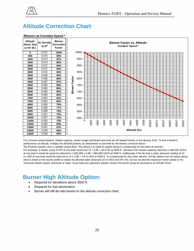
Altitude Above SeaLevel (ft.)
0500
100015002000250030003500400045005000550060006500700075008000850090009500100001100012000130001400015000
*
The Phoenix
For constanperformance
Blowers
For exampleat sea level in. H2O at swhat is listemaximum b
ude Cor
er HighRequired for eRequired for fu
urner will still
a Air Density
lb./ft3Co
0.0770.0750.0740.0730.0720.0710.0700.0690.0680.0670.0660.0650.0640.0630.0620.0610.0600.0590.0580.0570.0570.0550.0530.0510.0500.048
x burners uses a
nt speed blowers,e at altitude, mult
at Constant S
e: A blower usingit would be would
sea level would beed on the burner pblower speed, whi
rrection
h Altitudlevations abouel atomizatio de-rate base
Blower orrection Factor
100%99%97%96%94%93%92%90%89%87%86%85%84%82%81%80%79%77%76%75%74%72%69%67%65%63%
variable speed d
blower capacitytiply the desired
Speed *
g 75 HP at sea led be reduced to 1e reduced to 10 xprofile to obtain thichever is lower.
Blo
we
rF
acto
r
n Chart
de Optiove 3500 ft. on. ed on the altitu
drive. This allows
, power usage anproperty as deter
evel would use 751,000,000 x 0.86 x 0.86 = 8.6 in H2he desired static If you have any q
50%
55%
60%
65%
70%
75%
80%
85%
90%
95%
100%
0 100
0
Blo
we
r F
acto
r
Phoenix
29
t
ion:
ude correctio
it to have its spe
nd blower pressurmined at sea lev
5 * 0.86 = 64.5 HP= 860,000 SCFH
2O at 5000 ft. Topressure (10 in H
questions please
100
0
200
0
300
0
x FURY - O
n chart.
eed raised to com
re are all related vel by the blower
P at 5000 ft. LikeH at 5000 ft. Addio compensate for H2O) and HP (75contact the burn
400
0
500
0
600
0
A
Blower FactoConstan
Operation and
mpensate for the l
linearly to the decorrection factor
ewise if the bloweitionally if the fanthis lower densit
5). Do not exceeder group for assis
700
0
800
0
900
0
Altitude (ft.)
or vs. Altitudent Speed *
d Service M
ower air density.
ensity of air. To fi.
er capacity had bn had a static prety, the fan speed d the maximum mstance at 423-86
100
00
110
00
120
00
e
anual
nd a burner's
een 1,000,000 Sssure reading of must be raised a
motor speed or th7-4210.
120
00
130
00
140
00
CFH 10 above
he
150
00

Ill
Illu
lustration 14
ustration 14b
4a – Burner H
b – Burner H
Phoenix
30
High Altitud
High Altitud
x FURY - O
de Blower Ki
de Blower Ki
Operation and
Kit Addition
it Addition
d Service Manual

RecoBlow
S
ommendwer Kit:
Ill
Ill
tep (1) Remo
ded Ins
ustration 15
ustration 16
ove the Burne
stallatio
– Burner Hi
– Burner Hi
er inlet plate a
Phoenix
31
on Guid
igh Altitude
igh Altitude
assembly loca
x FURY - O
de for H
Blower Kit
Blower Kit
ated above th
Operation and
High Alt
t Assembly
t Assembly
e Oil train ass
d Service M
titude
sembly.
anual

S
asth
S
Ill
tep (2) Installs shown in illu
hrough the cetep (3) Reins
ustration 17
l (bolt-on) covustration-17 anter of the flatall the burne
– Burner Hi
ver plates to tabove. Applyange. er inlet plate a
Phoenix
32
igh Altitude
he back flangy RTV liberally
assembly.
x FURY - O
Blower Kit
ge of the HA cy around the ½
Operation and
t Assembly
conversion we½” oil guide p
d Service M
eldment assepipe traveling
anual
embly

Sm
Sor
S3”pr
S F
enco
Ill
tep (4) Mountmounted on ru
tep (5) thru hrder to mounttep (6) Install” hose onto throvided in thetep (7) Make inally install thnd of the 3” pontrol system
ustration 18
t the High Altubber isolatingoles (Appropt the new blowl the 3” hose ohe 3” pipe on e kit. Trim anysure all hose
he pressure spipe on the bum.
– Burner Hi
itude Blower g pads providriately sized) wer motor assonto the boosthe burner ai
y excess 3” rues have been switch and preurner air damp
Phoenix
33
igh Altitude
Motor assemed by the venmay need to sembly. Matcster blower our damper and
ubber hose astighten in plaessure gaugeper and wire t
x FURY - O
Blower Kit
mbly. Note thandor. be placed in
ch drill holes wutlet first. Finad secure boths needed. ace and are ree assembly onthe switch int
Operation and
t Assembly
at all motor as
the existing bwith blower mally install theh ends with ho
eady for operan the ¼” NPTo the limit str
d Service M
ssemblies mu
base frame inmotor frame. e other end ofose clamps
ation. T coupling at ting of the bur
anual
ust be
n
f the
the rner
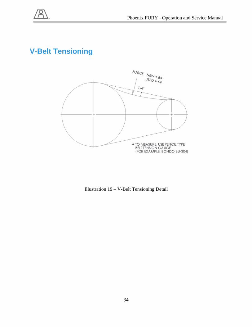
V-Be
lt Tensioning
Illusttration 19 – V
Phoenix
34
V-Belt Tens
x FURY - O
sioning Deta
Operation and
ail
d Service Manual