pfau-tec - the home depot · pdf filebefore you take your trike on the road...
TRANSCRIPT

360° 330° 300° 270° 240° 210° 180° 150° 120° 90° 60° 30° 0°
GmbH PFAU-Tec byreha-technik · entwicklung · konstruktion
Montage- und Betriebsanweisung
www.pfiff-vertrieb.de
Amico
Advanced
Alluminio
Ally
Bene
Capo
Classic
Collettivo
Comfort
Compagno
Elegance
Famoso
Fusione
Grazia
Lesto
Merano
Mobile
Napoli
Pfautomatic
Picco
Prato
Primo
Primo-Heinzmann
Primo-Quad
Proven
Robusto Deluxe
Robusto Standard
Scootertrike
Special
Unione
Deutsch England Nederland France
41
Welcome!
Trike maintenanceBefore each use(by the owner):
• Check and if needed tighten all screws and nuts,and the quick releases of the wheels.
• Check handlebar and handlebar stem for any dam-age and have these replaced where needed.
• Check brake assembly for proper function and ad-just as needed.
• Check tire pressure in compliance with the max.pressure value provided on the tires.
• Check the tire tread.
• Check the lighting system.
• Check the grips on the handlebars for proper seat-ing and wear.
• Check the screw connections of the suspensionfor proper seating, and the suspension fork forproper function and clearance at the bearing points.
Monthly (by the owner)
• Check the steering head - if necessary, have it relu-bricated and adjusted by an authorised workshop.
• Check and oil cable pulleys. Ensure that cables arenot twisted. Do not oil Te]on-covered cable sleeves.
• Check and where necessary adjust chain tension, andclean and lubricate chain. Check and adjust rearwheel track where necessary.
As needed, but at least once a year(by authorised garage)
• Check bottom brackets and lubricate as needed.
• Lubricate pedal bearing, check and adjust bearingclearance (or replace) as needed.
• Check and adjust hub gear as needed.
• Check steering head bearing and lubricate and ad-just as needed.
• Check handlebar and handlebar stem for any dam-age and replace as needed.
• Check brake system for proper function and adjustas needed. In case of diminished brake perform-
ance, check the condition of hand lever, cable pul-leys, brake lever and brake lining; adjust or replaceas needed. Lubricate joints and bearing points. Re-place twisted or nicked cable strands.
• Check rims for radial and lateral run-out. Check andadjust spoke tension as needed.
• Check the tire tread.
• Check the lighting system.
• Check and lubricate rear wheel brake hub as needed.
• Check all screw connections for proper seating andsuspension elements for clearance.
• Check all screw connections on suspension forks forproper seating and suspension elements for clearance.
• Check frame and fork for any damage and replaceas needed.
As needed by the owner:
• Check and where necessary adjust chain tension, andclean and lubricate chain.
• Check chain for wear, lubricate or replace as needed.
• Check pedal bearing mounting and repair as needed.
• Check pedal clearance.
• Check hub gear settings.
• Check handlebar and handlebar stem for any dam-age and replace as needed.
• Check brake assembly for proper function and ad-just as needed.
• Check the tire pressure and tread.
• Check the lighting system.
InspectionThe \rst inspection should be carried out after approx.500 km. Work out a suitable maintenance schedulewith your authorised dealer.
Note:You will \nd a maintenance task table for futuremaintenance/inspection dates in the appendix of thismanual.
We would like to congratulate you on the purchase of your PFAU-Tec trike.Please read and comply with the following instructions carefully to ensureyour long-term enjoyment of our vehicle.

42
Proper maintenance of the trikeThe trike must undergo periodic maintenance to en-sure its proper function and optimised appearance.Please note the following important points:
• Periodic maintenance carried out by specialists willensure the conservation of the trike’s value. The fol-lowing steps will help prevent corrosion and otherdamage:
• Never attempt to remove dried in dirt. Always usewater and a soft cloth or sponge. Do not clean thetrike with a power washer, as this could lead todamage to bearings, paint or decor.
• Never use any aggessive cleaning additives.
• Always touch up any damage to the paint immedi-ately.
• Treat corrodable parts with appropriate conser-vation and care products.
• Store your trike in a dry location, where tempera-tures remain constant.
• Check the tire pressure before long-term storage,and adjust the tire pressure as needed to complywith the value recommended by the manufacturer.

43
Content
1. General information1.1 Safety instructions . . . . . . . . . . . . . . . 44
2. Before you take your trike on the road2.1 Pretrip checks & inspections . . . . . . . . . 45
2.2 Checks as you get going . . . . . . . . . . . 45
2.3 Assembly and disassembly of the frame . . 46
2.4 Screws & nuts . . . . . . . . . . . . . . . . . . . 46
2.5 Brakes & brake pads . . . . . . . . . . . . . . 46
2.6 Saddle . . . . . . . . . . . . . . . . . . . . . . . . 46
2.7 Handlebars . . . . . . . . . . . . . . . . . . . . . 47
2.8 Pedals . . . . . . . . . . . . . . . . . . . . . . . . . 47
2.9 Tire pressure . . . . . . . . . . . . . . . . . . . . 47
2.10 Adjusting the suspension . . . . . . . . . 47
2.11 Lighting system . . . . . . . . . . . . . . . . 48
2.12 Adjusting the headlamp . . . . . . . . . . 48
2.13 Activating & deactivating the
dynamo . . . . . . . . . . . . . . . . . . . . . . 48
2.14 Gear system . . . . . . . . . . . . . . . . . . . 48
2.15 Chain . . . . . . . . . . . . . . . . . . . . . . . . 48
2.15.1 Chain tension in tandems . . . . . . . 49
2.16 Initial test drives . . . . . . . . . . . . . . . . 49
2.17 Special instructions/ScooterTrike characteristics . . . . . . . . 49
2.17.1 ScooterTrike seating position . . . . . 49
2.17.2 ScooterTrike handlebar position . . . 51
2.17.3 Special features of the ScooterTrike 51
2.17.4 Starting and the \rst meters . . . . . 52
2.17.5 ScooterTrike reverse option . . . . . . 52
2.17.6 Troubleshooting . . . . . . . . . . . . . . . 52
2.18 Special instructions/Tandem characteristics . . . . . . . . . . . 52
2.18.1 Steering system/steering position . . 52
2.18.2 The \rst meters . . . . . . . . . . . . . . . 53
2.18.3 Special driving characteristics . . . . . 53
3. Care & maintenance3.1 Cleaning . . . . . . . . . . . . . . . . . . . . . . . 53
3.2 Checks . . . . . . . . . . . . . . . . . . . . . . . . 53
3.3 Spokes . . . . . . . . . . . . . . . . . . . . . . . . 54
3.4 Brakes . . . . . . . . . . . . . . . . . . . . . . . . 54
3.4.1 Special safety instructions . . . . . . . . 54
3.4.2 Adjusting and loosening the
brake lever . . . . . . . . . . . . . . . . . . . 54
3.4.3 Adjusting the brake pads . . . . . . . . . 54
3.4.4 Brakes & brake pad adjustment . . . . 54
3.4.5 Replacing/adjusting the brake pads . . 55
3.5 Lubrication . . . . . . . . . . . . . . . . . . . . . 55
3.6 Front wheel . . . . . . . . . . . . . . . . . . . . 56
3.6.1 Attachment . . . . . . . . . . . . . . . . . . . 56
3.6.2 Bearing clearance . . . . . . . . . . . . . . 56
3.7 Rear wheel . . . . . . . . . . . . . . . . . . . . . 57
3.8 Pedal crank . . . . . . . . . . . . . . . . . . . . . 57
3.9 Lighting system components . . . . . . . 57
3.10 Dynamo setting . . . . . . . . . . . . . . . . 57
4. Intended use4.1 Load speci\cations . . . . . . . . . . . . . . . 57
4.2 Street trikes . . . . . . . . . . . . . . . . . . . . 57
4.3 Tips on environmental protection . . . . 57
4.4 Tips for your safety . . . . . . . . . . . . . . . 57
4.5 General information . . . . . . . . . . . . . . 57
4.6 Road traf\c . . . . . . . . . . . . . . . . . . . . 58
4.7 Liability . . . . . . . . . . . . . . . . . . . . . . . . 58
4.8 Warranty information . . . . . . . . . . . . . 59
5. The power assist system5.1 Basic information on power assist
systems . . . . . . . . . . . . . . . . . . . . . . . . 59
AppendixExploded drawings . . . . . . . . . . . . . . 60 - 71
handover protocol . . . . . . . . . . . . . . . . . . 72
Maintenance log . . . . . . . . . . . . . . . . . . . 73
Bicycle passport . . . . . . . . . . . . . . . . . . . . 74
Declaration of conformity . . . . . . . . . 75 - 77

44
General information
Dear customer,this brand name trike was an excellent choice. We have carefully packaged your trike, so that you will receiveit in perfect condition. Nevertheless, please do check your trike thoroughly for any damage.
1.1 Safety instructionsIn these assembly and operating instructions, all sections containing safety warnings are highlighted with ashaded background. Make sure to pass on these instructions to any other user as well.
The following table lists the max. load speciOcations for individual models:
The same information is also shown on the seat frame tubing of each model!This vehicle is intended for use on level, solid surfaces only!
The package leaPet and additional sheets are part of the operating instructions!
Max. load capacity (kg) Max. luggage load (kg)
Model Amico (12", 16") 50 kg 5 kg
Model Amico (20", 24", 26") 100 kg 10 kg
Model Advanced 100 kg 20 kg
Model Ally 100 kg 20 kg
Model Aluminio 100 kg 20 kg
Model Bene 100 kg 20 kg
Model Capo 100 kg 20 kg
Model Classic 100 kg 20 kg
Model Collettivo rear 100 kg, front 60 kg 10 kg
Model Comfort 100 kg 20 kg
Model Compagno rear 80 kg, front 80 kg 10 kg
Model Elegance 100 kg 20 kg
Model Famoso 50 kg 5 kg
Model Fusione rear 80 kg, front 80 kg 10 kg
Model Grazia 120 kg 25 kg
Model Lesto 12" 40 kg 10 kg
Model Lesto 16" 50 kg 10 kg
Model Lesto 20" 70 kg 10 kg
Model Merano 100 kg 20 kg
Model Mobile 100 kg 10 kg
Model Napoli 100 kg 20 kg
Model Pfautomatic 100 kg 20 kg
Model Picco 50 kg 5 kg
Model Prato 160 kg 20 kg
Model Primo 100 kg 20 kg
Model Primo-Heinzmann 100 kg 20 kg
Model Primo-Quad 160 kg 20 kg
Model Proven 100 kg 20 kg
Model Robusto Deluxe 120 kg 25 kg
Model Robusto Standard 120 kg 25 kg
Model Scootertrike 100 kg 20 kg
Model Special 100 kg 20 kg
Model Unione rear 80 kg, front 80 kg 10 kg
45
Before you take your trike on the road
2. Before you take your trike on the roadCheck all essential systems before you take yourtrike on the road.
2.1 Pretrip checks & inspectionsThe following points are of special importance foryour pretrip check:
a. Rigidity of the handlebarsTurn and rattle the handlebars to ensure their properseating. Check the proper alignment of the handle-bars with the front wheel. Any loose parts must betightened.
b. Function of the bellCheck the function and sound of the bell.
c. Brake lever tensionPull the front wheel and rear wheel brake and ensurethat the brake pads touch the wheel rim with 50% offull lever tension.
d. Saddle & handlebar heightWith the saddle at its correct height, you will be ableto touch the ground with your toes. The handlebarsare at the correct height, when you grab them withlightly angled elbows from a seated position.
e. Attaching the luggage rackEnsure the proper seating of the luggage rack.
f. Cleanliness of rePector and tail lightCheck re]ectors and tail lights, clean off any dirt. Replacepart in case of any damage. (Ask your authorised dealer).
g. Axle OttingCheck front and rear wheels for correct attachmentand concentricity, tighten as needed.
h. Tire pressure, wear and conditionEnsure correct tire pressure. Incorrecttire pressure can cause punctures or wobbling. Checkthe tires for wear and for any foreign bodies in thetread. See the tire inscription for max. tire pressure.Otherwise ask your authorised dealer.
i. Chain slackCheck for proper chain slack (the chain should haveabout 10 to 25 mm slack in the middle). If the chain istoo slack, it can jump out of its track, which too littleslack could lead to the chain breaking.
j. Fixture of moving parts(e.g. pedals)Ensure that all moving parts, like pedals, are pro-perly attached and can turn freely. Tighten any loosescrews.
k. Proper seating of the saddle height adjustmentleverEnsure the proper seating of the saddle heightadjustment lever.
l. Battery charge in electric bicylesTurn the main contactor to the ON position and checkthe battery charge indicators.
m. Proper seating of the battery in electric bicyclesEnsure the correct and proper seating of the battery.
2.2 Checks as you get goingn. Gear system functionContact your authorised dealer immediately if thegear system is stiff or not functioning at all.
o. Function and alignment of the head lampCheck if the beam of the head lamp illuminates acircular section of the road at distance of 10 m. Amalfunction of the head lamp could be caused by aburned out bulb. Replace the bulb with a new bulb ofthe same type (activate/deactivate the dynamo onlywhen the wheel is standing still).
p. Function of the power assist system in electricbicyclesCheck the power assist system for proper function atthe start of your drive. Stop immediately and contactyour authorised dealer if you hear any unusual noises,see any smoke or smell any unusual odours comingfrom the system.
WarningThe power assist system consists of high-precisioncomponents.Never attempt to remove the cover or dissassemblethe system yourself. Always contact your authoriseddealer in case of faults or queries.
46
Before you take your trike on the road
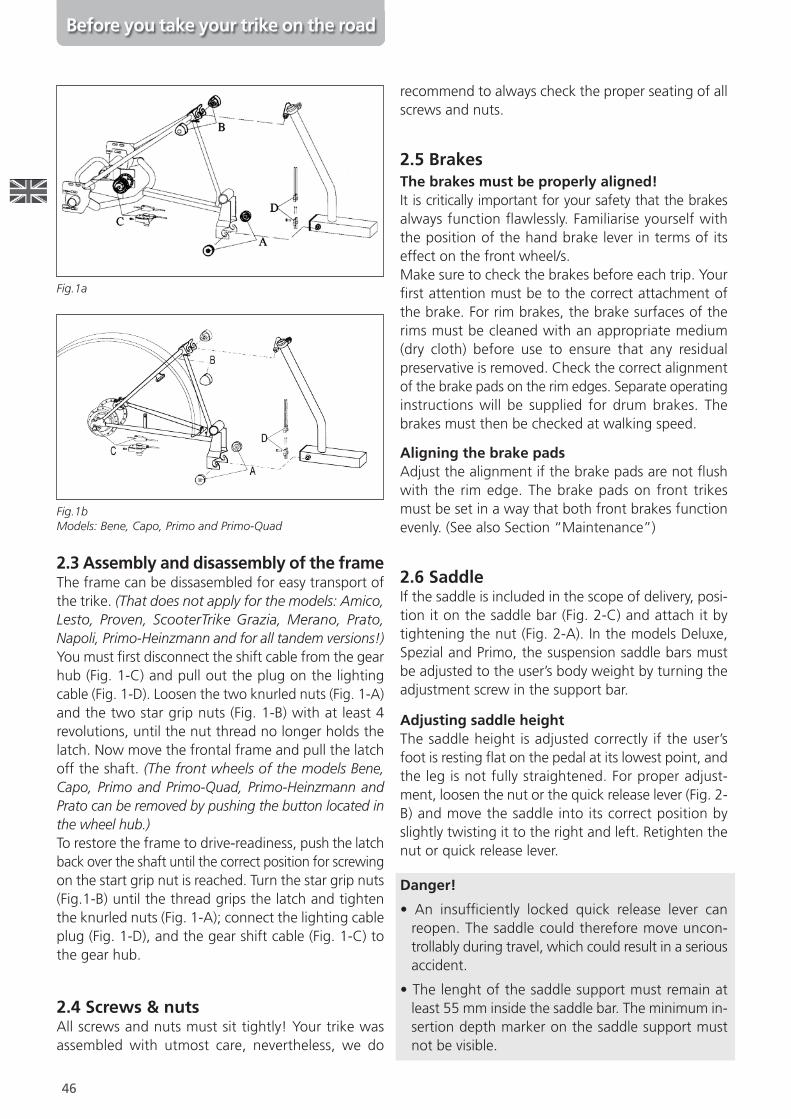
2.3 Assembly and disassembly of the frameThe frame can be dissasembled for easy transport ofthe trike. (That does not apply for the models: Amico,Lesto, Proven, ScooterTrike Grazia, Merano, Prato,Napoli, Primo-Heinzmann and for all tandem versions!)You must \rst disconnect the shift cable from the gearhub (Fig. 1-C) and pull out the plug on the lightingcable (Fig. 1-D). Loosen the two knurled nuts (Fig. 1-A)and the two star grip nuts (Fig. 1-B) with at least 4revolutions, until the nut thread no longer holds thelatch. Now move the frontal frame and pull the latchoff the shaft. (The front wheels of the models Bene,Capo, Primo and Primo-Quad, Primo-Heinzmann andPrato can be removed by pushing the button located inthe wheel hub.)To restore the frame to drive-readiness, push the latchback over the shaft until the correct position for screwingon the start grip nut is reached. Turn the star grip nuts(Fig.1-B) until the thread grips the latch and tightenthe knurled nuts (Fig. 1-A); connect the lighting cableplug (Fig. 1-D), and the gear shift cable (Fig. 1-C) tothe gear hub.
2.4 Screws & nutsAll screws and nuts must sit tightly! Your trike wasassembled with utmost care, nevertheless, we do
recommend to always check the proper seating of allscrews and nuts.
2.5 BrakesThe brakes must be properly aligned!It is critically important for your safety that the brakesalways function ]awlessly. Familiarise yourself withthe position of the hand brake lever in terms of itseffect on the front wheel/s.Make sure to check the brakes before each trip. Your\rst attention must be to the correct attachment ofthe brake. For rim brakes, the brake surfaces of therims must be cleaned with an appropriate medium(dry cloth) before use to ensure that any residualpreservative is removed. Check the correct alignmentof the brake pads on the rim edges. Separate operatinginstructions will be supplied for drum brakes. Thebrakes must then be checked at walking speed.
Aligning the brake padsAdjust the alignment if the brake pads are not ]ushwith the rim edge. The brake pads on front trikesmust be set in a way that both front brakes functionevenly. (See also Section “Maintenance”)
2.6 SaddleIf the saddle is included in the scope of delivery, posi-tion it on the saddle bar (Fig. 2-C) and attach it bytightening the nut (Fig. 2-A). In the models Deluxe,Spezial and Primo, the suspension saddle bars mustbe adjusted to the user’s body weight by turning theadjustment screw in the support bar.
Adjusting saddle heightThe saddle height is adjusted correctly if the user’sfoot is resting ]at on the pedal at its lowest point, andthe leg is not fully straightened. For proper adjust-ment, loosen the nut or the quick release lever (Fig. 2-B) and move the saddle into its correct position byslightly twisting it to the right and left. Retighten thenut or quick release lever.
Danger!
• An insuf\ciently locked quick release lever canreopen. The saddle could therefore move uncon-trollably during travel, which could result in a seriousaccident.
• The lenght of the saddle support must remain atleast 55 mm inside the saddle bar. The minimum in-sertion depth marker on the saddle support mustnot be visible.
Fig.1a
Fig.1bModels: Bene, Capo, Primo and Primo-Quad
47
Before you take your trike on the road
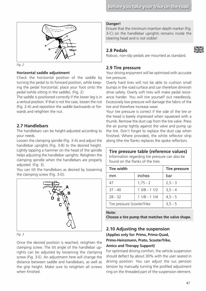
Horizontal saddle adjustmentCheck the horizontal position of the saddle byturning the pedal to its forward position, while keep-ing the pedal horizontal; place your foot onto thepedal (while sitting in the saddle). (Fig. 2)The saddle is positioned correctly if the lower leg is ina vertical position. If that is not the case, loosen the nut(Fig. 2-A) and reposition the saddle backwards or for-wards and retighten the nut.
2.7 HandlebarsThe handlebars can be height-adjusted according toyour needs.Loosen the clamping spindle (Fig. 3-A) and adjust thehandlebar uprights (Fig. 3-B) to the desired height.Lightly tapping a hammer on the head of the spindlehelps adjusting the handlebar uprights. Retighten theclamping spindle when the handlebars are properlyadjusted. (Fig. 3).You can tilt the handlebars as desired by looseningthe clamping screw (Fig. 3-D).
Once the desired position is reached, retighten theclamping screw. The tilt angle of the handlebar up-rights can be adjusted by loosening the clampingscrew (Fig. 3-E). An adjustment here will change thedistance between saddle and handlebars, as well asthe grip height. Make sure to retighten all screwswhen \nished.
Danger!Ensure that the minimum insertion depth marker (Fig.3-C) on the handlebar uprights remains inside thesteering head and is not visible!
2.8 PedalsRobust, non-slip pedals are mounted as standard.
2.9 Tire pressureYour driving enjoyment will be optimised with accuratetire pressure.Overly hard tires will not be able to cushion smallbumps in the road surface and can therefore diminishdrive safety. Overly soft tires will make pedal resist-ance harder. You will tire yourself out needlessly.Excessively low pressure will damage the fabric of thetire and therefore increase wear.Your tire pressure is correct if the side of the tire orthe tread is barely impressed when squeezed with athumb. Remove the dust cap from the tire valve. Pressthe air pump tightly against the valve and pump upthe tire. Don’t forget to replace the dust cap when\nished. Where provided, the white re]ector stripalong tthe tire ]anks replaces the spoke re]ectors.
Note:Choose a tire pump that matches the valve shape.
2.10 Adjusting the suspension(Applies only for: Primo, Primo-Quad,Primo-Heinzmann, Prato, ScooterTrike,Amico and Therapy Support)For optimised driving comfort, the vehicle suspensionshould de]ect by about 30% with the user seated indriving position. You can adjust the sus pensiontension by manually turning the pro\led adjustmentring on the threaded part of the suspension element.
Fig. 2
Fig. 3
Tire pressure table (reference values)Information regarding tire pressure can also befound on the ]anks of the tires
Tire width Tire pressure
mm inches bar
47 1,75 - 2 2,5 - 3
37 - 40 1 3/8 - 1 1/2 3,5 - 4
28 - 32 1 1/8 - 1 1/4 4,5 - 5
Tire pressure ScooterTrike 3,5 - 5
48
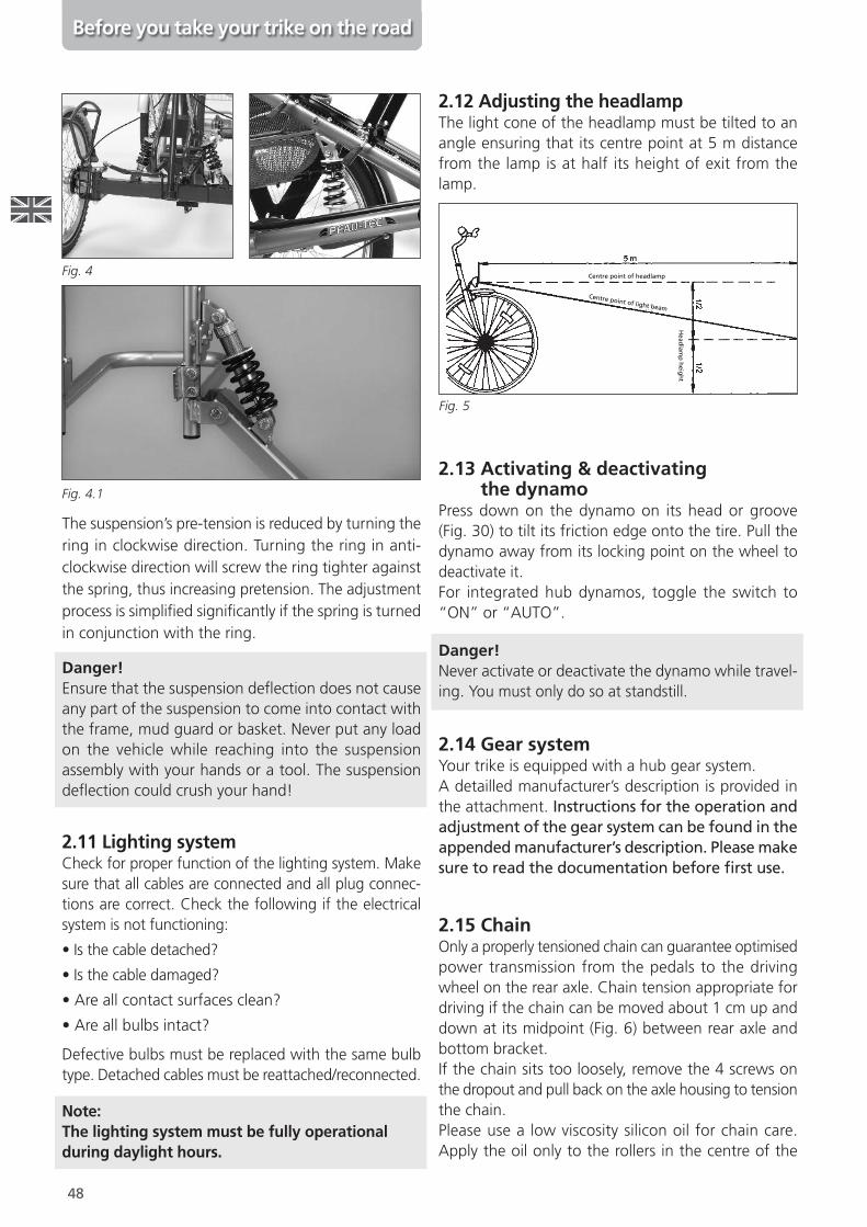
The suspension’s pre-tension is reduced by turning thering in clockwise direction. Turning the ring in anti-clockwise direction will screw the ring tighter againstthe spring, thus increasing pretension. The adjustmentprocess is simpli\ed signi\cantly if the spring is turnedin conjunction with the ring.
Danger!Ensure that the suspension de]ection does not causeany part of the suspension to come into contact withthe frame, mud guard or basket. Never put any loadon the vehicle while reaching into the suspensionassembly with your hands or a tool. The suspensionde]ection could crush your hand!
2.11 Lighting systemCheck for proper function of the lighting system. Makesure that all cables are connected and all plug connec-tions are correct. Check the following if the electricalsystem is not functioning:
• Is the cable detached?
• Is the cable damaged?
• Are all contact surfaces clean?
• Are all bulbs intact?
Defective bulbs must be replaced with the same bulbtype. Detached cables must be reattached/reconnected.
Note:The lighting system must be fully operationalduring daylight hours.
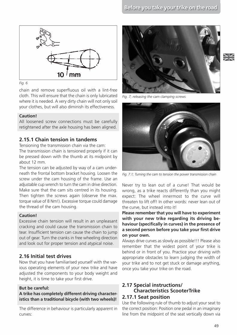
2.12 Adjusting the headlampThe light cone of the headlamp must be tilted to anangle ensuring that its centre point at 5 m distancefrom the lamp is at half its height of exit from thelamp.
2.13 Activating & deactivatingthe dynamo
Press down on the dynamo on its head or groove(Fig. 30) to tilt its friction edge onto the tire. Pull thedynamo away from its locking point on the wheel todeactivate it.For integrated hub dynamos, toggle the switch to“ON” or “AUTO”.
Danger!Never activate or deactivate the dynamo while travel-ing. You must only do so at standstill.
2.14 Gear systemYour trike is equipped with a hub gear system.A detailled manufacturer’s description is provided inthe attachment. Instructions for the operation andadjustment of the gear system can be found in theappendedmanufacturer’s description. Please makesure to read the documentation before $rst use.
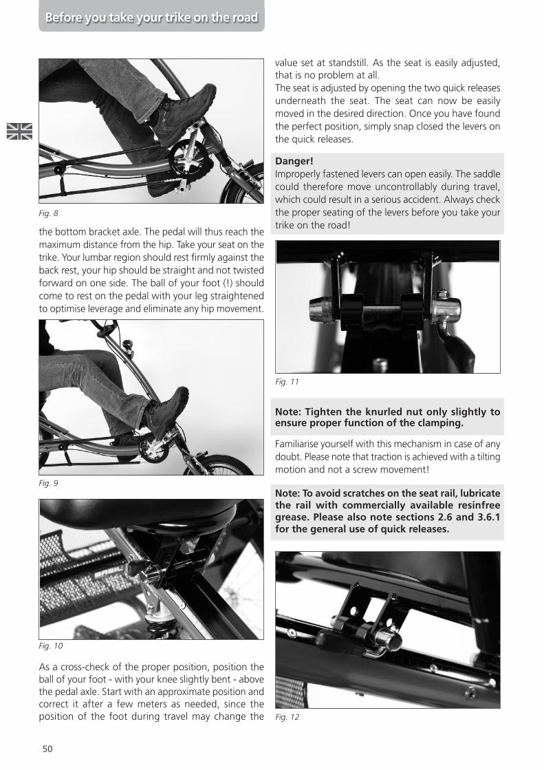
2.15 ChainOnly a properly tensioned chain can guarantee optimisedpower transmission from the pedals to the drivingwheel on the rear axle. Chain tension appropriate fordriving if the chain can be moved about 1 cm up anddown at its midpoint (Fig. 6) between rear axle andbottom bracket.If the chain sits too loosely, remove the 4 screws onthe dropout and pull back on the axle housing to tensionthe chain.Please use a low viscosity silicon oil for chain care.Apply the oil only to the rollers in the centre of the
Before you take your trike on the road
Fig. 4
Fig. 4.1
Centre point of light beam
Head
lamp
heig
ht
Centre point of headlamp
Fig. 5
49
chain and remove super]uous oil with a lint-freecloth. This will ensure that the chain is only lubricatedwhere it is needed. A very dirty chain will not only soilyour clothes, but will also diminish its effectiveness.
Caution!All loosened screw connections must be carefullyretightened after the axle housing has been aligned.
2.15.1 Chain tension in tandemsTensioning the transmission chain via the cam:The transmission chain is tensioned properly if it canbe pressed down with the thumb at its midpoint byabout 12 mm.The tension can be adjusted by way of a cam under-neath the frontal bottom bracket housing. Loosen thescrew under the cam housing of the frame. Use anadjustable cup wrench to turn the cam in drive direction.Make sure that the cam sits centred in its housing.Then tighten the screws again (observe the max.torque value of 8 Nm!). Excessive torque could damagethe thread of the cam housing.
Caution!Excessive chain tension will result in an unpleasantcracking and could cause the transmission chain totear. Insuf\cient tension can cause the chain to jumpout of gear. Turn the cranks in free wheeling directionand look out for proper tension and atypical noise.
2.16 Initial test drivesNow that you have familiarised yourself with the var-ious operating elements of your new trike and haveadjusted the components to your body weight andheight, it is time to take your \rst drive.
But be careful:A trike has completely different driving character-istics than a traditional bicycle (with two wheels)!
The difference in behaviour is particularly apparent incurves:
Never try to lean out of a curve! That would bewrong, as a trike reacts differently than you mightexpect: The wheel innermost to the curve willthreaten to lift off! In other words: never lean out ofthe curve, but instead into it!Please remember that youwill have to experimentwith your new trike regarding its driving be-haviour (speciOcally in curves) in the presence ofa second person before you take your Orst driveon your own.Always drive curves as slowly as possible!!! Please alsoremember that the widest point of your trike isbehind or in front of you. Practice your driving withappropriate obstacles to learn judging the width ofyour trike and to not get stuck or damage anything,once you take your trike on the road.
2.17 Special instructions/Characteristics ScooterTrike
2.17.1 Seat positionUse the following rule of thumb to adjust your seat tothe correct position: Position one pedal in an imaginaryline from the midpoint of the seat vertically down via
Before you take your trike on the road
Fig. 6
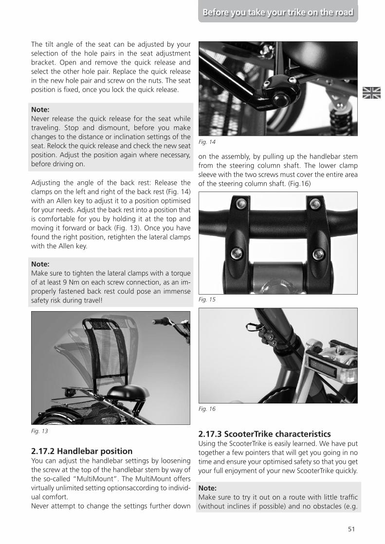
Fig. 7; releasing the cam clamping screws
Fig. 7.1; Turning the cam to tension the power transmission chain
50
the bottom bracket axle. The pedal will thus reach themaximum distance from the hip. Take your seat on thetrike. Your lumbar region should rest \rmly against theback rest, your hip should be straight and not twistedforward on one side. The ball of your foot (!) shouldcome to rest on the pedal with your leg straightenedto optimise leverage and eliminate any hip movement.
As a cross-check of the proper position, position theball of your foot - with your knee slightly bent - abovethe pedal axle. Start with an approximate position andcorrect it after a few meters as needed, since theposition of the foot during travel may change the
value set at standstill. As the seat is easily adjusted,that is no problem at all.The seat is adjusted by opening the two quick releasesunderneath the seat. The seat can now be easilymoved in the desired direction. Once you have foundthe perfect position, simply snap closed the levers onthe quick releases.
Danger!Improperly fastened levers can open easily. The saddlecould therefore move uncontrollably during travel,which could result in a serious accident. Always checkthe proper seating of the levers before you take yourtrike on the road!
Note: Tighten the knurled nut only slightly toensure proper function of the clamping.
Familiarise yourself with this mechanism in case of anydoubt. Please note that traction is achieved with a tiltingmotion and not a screw movement!
Note: To avoid scratches on the seat rail, lubricatethe rail with commercially available resinfreegrease. Please also note sections 2.6 and 3.6.1for the general use of quick releases.
Before you take your trike on the road
Fig. 8
Fig. 9
Fig. 10
Fig. 11
Fig. 12
51
Before you take your trike on the road
The tilt angle of the seat can be adjusted by yourselection of the hole pairs in the seat adjustmentbracket. Open and remove the quick release andselect the other hole pair. Replace the quick releasein the new hole pair and screw on the nuts. The seatposition is \xed, once you lock the quick release.
Note:Never release the quick release for the seat whiletraveling. Stop and dismount, before you makechanges to the distance or inclination settings of theseat. Relock the quick release and check the new seatposition. Adjust the position again where necessary,before driving on.
Adjusting the angle of the back rest: Release theclamps on the left and right of the back rest (Fig. 14)with an Allen key to adjust it to a position optimisedfor your needs. Adjust the back rest into a position thatis comfortable for you by holding it at the top andmoving it forward or back (Fig. 13). Once you havefound the right position, retighten the lateral clampswith the Allen key.
Note:Make sure to tighten the lateral clamps with a torqueof at least 9 Nm on each screw connection, as an im-properly fastened back rest could pose an immensesafety risk during travel!
2.17.2 Handlebar positionYou can adjust the handlebar settings by looseningthe screw at the top of the handlebar stem by way ofthe so-called “MultiMount”. The MultiMount offersvirtually unlimited setting optionsaccording to individ-ual comfort.Never attempt to change the settings further down
on the assembly, by pulling up the handlebar stemfrom the steering column shaft. The lower clampsleeve with the two screws must cover the entire areaof the steering column shaft. (Fig.16)
2.17.3 ScooterTrike characteristicsUsing the ScooterTrike is easily learned. We have puttogether a few pointers that will get you going in notime and ensure your optimised safety so that you getyour full enjoyment of your new ScooterTrike quickly.
Note:Make sure to try it out on a route with little traf\c(without inclines if possible) and no obstacles (e.g.
Fig. 13
Fig. 14
Fig. 15
Fig. 16
52
parked cars), where you can concentrate fully on fa-miliarising yourself with the new vehicle.
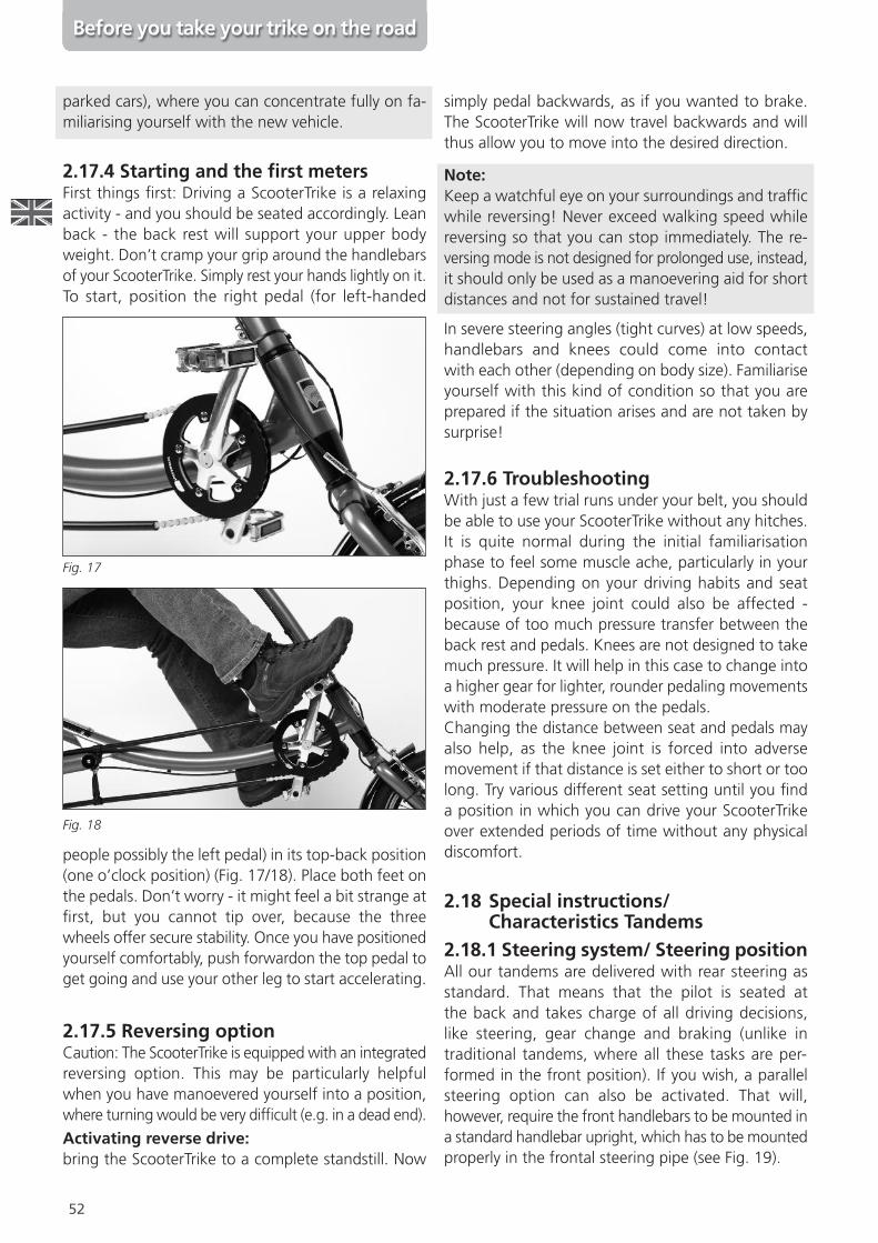
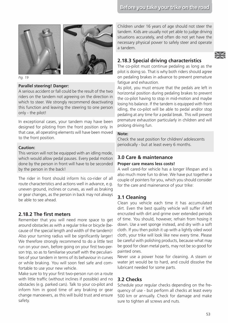
2.17.4 Starting and the Orst metersFirst things \rst: Driving a ScooterTrike is a relaxingactivity - and you should be seated accordingly. Leanback - the back rest will support your upper bodyweight. Don’t cramp your grip around the handlebarsof your ScooterTrike. Simply rest your hands lightly on it.To start, position the right pedal (for left-handed
people possibly the left pedal) in its top-back position(one o’clock position) (Fig. 17/18). Place both feet onthe pedals. Don’t worry - it might feel a bit strange at\rst, but you cannot tip over, because the threewheels offer secure stability. Once you have positionedyourself comfortably, push forwardon the top pedal toget going and use your other leg to start accelerating.
2.17.5 Reversing optionCaution: The ScooterTrike is equipped with an integratedreversing option. This may be particularly helpfulwhen you have manoevered yourself into a position,where turning would be very dif\cult (e.g. in a dead end).
Activating reverse drive:bring the ScooterTrike to a complete standstill. Now
simply pedal backwards, as if you wanted to brake.The ScooterTrike will now travel backwards and willthus allow you to move into the desired direction.
Note:Keep a watchful eye on your surroundings and traf\cwhile reversing! Never exceed walking speed whilereversing so that you can stop immediately. The re-versing mode is not designed for prolonged use, instead,it should only be used as a manoevering aid for shortdistances and not for sustained travel!
In severe steering angles (tight curves) at low speeds,handlebars and knees could come into contactwith each other (depending on body size). Familiariseyourself with this kind of condition so that you areprepared if the situation arises and are not taken bysurprise!
2.17.6 TroubleshootingWith just a few trial runs under your belt, you shouldbe able to use your ScooterTrike without any hitches.It is quite normal during the initial familiarisationphase to feel some muscle ache, particularly in yourthighs. Depending on your driving habits and seatposition, your knee joint could also be affected -because of too much pressure transfer between theback rest and pedals. Knees are not designed to takemuch pressure. It will help in this case to change intoa higher gear for lighter, rounder pedaling movementswith moderate pressure on the pedals.Changing the distance between seat and pedals mayalso help, as the knee joint is forced into adversemovement if that distance is set either to short or toolong. Try various different seat setting until you \nda position in which you can drive your ScooterTrikeover extended periods of time without any physicaldiscomfort.
2.18 Special instructions/Characteristics Tandems
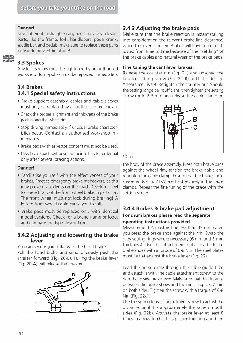
2.18.1 Steering system/ Steering positionAll our tandems are delivered with rear steering asstandard. That means that the pilot is seated atthe back and takes charge of all driving decisions,like steering, gear change and braking (unlike intraditional tandems, where all these tasks are per-formed in the front position). If you wish, a parallelsteering option can also be activated. That will,however, require the front handlebars to be mounted ina standard handlebar upright, which has to be mountedproperly in the frontal steering pipe (see Fig. 19).
Fig. 17
Fig. 18
Before you take your trike on the road
53
Parallel steering! Danger:A serious accident or fall could be the result of the tworiders on the tandem not agreeing on the direction inwhich to steer. We strongly recommend deactivatingthis function and leaving the steering to one persononly - the pilot!
In exceptional cases, your tandem may have beendesigned for piloting from the front position only. Inthat case, all operating elements will have been movedto the front position.
Caution:This version will not be equipped with an idling mode,which would allow pedal pauses. Every pedal motiondone by the person in front will have to be secondedby the person in the back!
The rider in front should inform his co-rider of allroute characteristics and actions well in advance, e.g.uneven ground, inclines or curves, as well as brakingor gear changes, as the person in back may not alwaysbe able to see ahead.
2.18.2 The Orst metersRemember that you will need more space to getaround obstacles as with a regular trike or bicycle (be-cause of the special length and width of the tandem)!Also your turning radius will be signi\cantly larger!We therefore strongly recommend to do a little testrun on your own, before going on your \rst two-per-son trip, so as to familiarise yourself with the peculiari-ties of your tandem in terms of its behaviour in curvesor while braking. You will soon feel safe and com-fortable to use your new vehicle.Make sure to try your \rst two-person run on a routewith little traf\c (without inclines if possible) and noobstacles (e.g. parked cars). Talk to your co-pilot andinform him in good time of any braking or gearchange manoevers, as this will build trust and ensuresafety.
Children under 16 years of age should not steer thetandem. Kids are usually not yet able to judge drivingsituations accurately, and often do not yet have thenecessary physical power to safely steer and operatea tandem.
2.18.3 Special driving characteristicsThe co-pilot must continue pedaling as long as thepilot is doing so. That is why both riders should agreeon pedaling brakes in advance to prevent prematurefatigue and exhaustion.As pilot, you must ensure that the pedals are left inhorizontal position during pedaling brakes to preventthe co-pilot having to stop in mid-motion and maybelosing his balance. If the tandem is equipped with frontidling, the co-pilot will be able to pedal and/or stoppedaling at any time for a pedal break. This will preventpremature exhaustion particularly in children and willprolong driving fun.
Note:Check the seat position for children/ adolescentsperiodically - but at least every 6 months.
3.0 Care & maintenanceProper care means less costs!A well cared-for vehicle has a longer lifespan and isalso much more fun to drive. We have put together acouple of pointers for you, which you should considerfor the care and mainenance of your trike:
3.1 CleaningClean you vehicle each time it has accumulateddirt. Even the best quality vehicle will suffer if leftencrusted with dirt and grime over extended periodsof time. You should, however, refrain from hosing itdown. Use a wet sponge instead, and dry with a softcloth. If you then polish it up with a lightly oiled woolcloth, your trike will look like new every time. Pleasebe careful with polishing products, because what maybe good for clean metal parts, may not be so good forpainted ones.Never use a power hose for cleaning. A steam orwater jet would be to hard, and could dissolve thelubricant needed for some parts.
3.2 ChecksSchedule your regular checks depending on the fre-quency of use - but perform all checks at least every500 km or annually. Check for damage and makesure to tighten all screws and nuts.
Before you take your trike on the road
Fig. 19
54
Danger!Never attempt to straighten any bends in safety-relevantparts, like the frame, fork, handlebars, pedal crank,saddle bar, and pedals. make sure to replace these partsinstead to brevent breakage!
3.3 SpokesAny lose spokes must be tightened by an authorisedworkshop. Torn spokes must be replaced immediately.
3.4 Brakes3.4.1 Special safety instructions• Brake support assembly, cables and cable sleevesmust only be replaced by an authorised technician
• Check the proper alignment and thickness of the brakepads along the wheel rim.
• Stop driving immediately if unusual brake character-istics occur. Contact an authorised workshop im-mediately.
• Brake pads with asbestos content must not be used.
• New brake pads will develop their full brake potentialonly after several braking actions.
Danger!
• Familiarise yourself with the effectiveness of yourbrakes. Practice emergency brake manoevers, as thismay prevent accidents on the road. Develop a feelfor the ef\cacy of the front wheel brake in particular.The front wheel must not lock during braking! Alocked front wheel could cause you to fall.
• Brake pads must be replaced only with identicalmodel versions. Check for a brand name or logo,and compare the type description.
3.4.2 Adjusting and loosening the brakelever
You can secure your trike with the hand brake.Pull the hand brake and simultaneously push thearrester forward (Fig. 20-B). Pulling the brake lever(Fig. 20-A) will release the arrester.
3.4.3 Adjusting the brake padsMake sure that the brake reaction is instant (takinginto consideration the relevant brake line clearance)when the lever is pulled. Brakes will have to be read-justed from time to time because of the “settling” ofthe brake cables and natural wear of the brake pads.
Fine tuning the cantilever brakes:Release the counter nut (Fig. 21) and unscrew theknurled setting screw (Fig. 21-B) until the desired“clearance” is set. Retighten the counter nut. Shouldthe setting range be insuf\cient, then tighten the settingscrew up to 2-3 mm and release the cable clamp on
the body of the brake assembly. Press both brake padsagainst the wheel rim, tension the brake cable andretighten the cable clamp. Ensure that the brake cablesleeve ends (Fig. 21-A) are held securely in the cableclamps. Repeat the \ne tuning of the brake with thesetting screw.
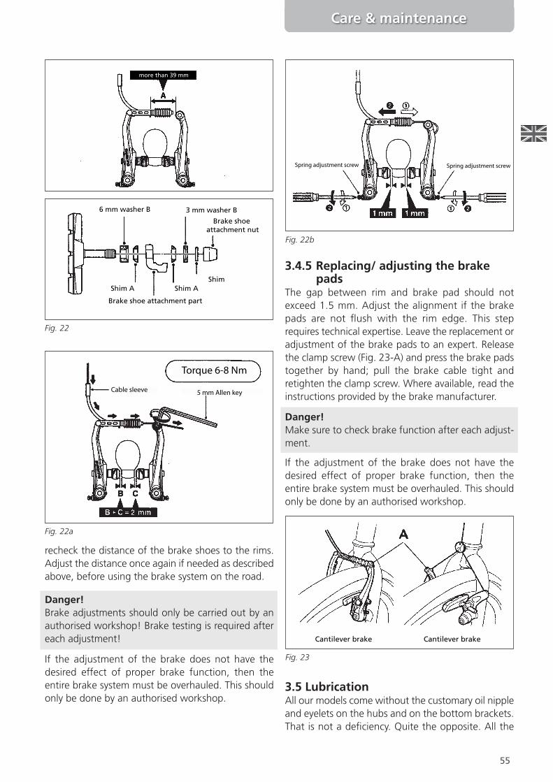
3.4.4 Brakes & brake pad adjustmentFor drum brakes please read the separateoperating instructions provided.Measurement A must not be less than 39 mm whenyou press the brake shoe against the rim. Swap thegrey setting rings where necessary (6 mm and 3 mmthickness). Use the attachment nuts to attach thebrake shoes with a torque of 6-8 Nm. The steel platesmust lie ]at against the brake lever (Fig. 22).
Lead the brake cable through the cable guide tubeand attach it with the cable attachment screw to theright-hand side brake lever. Make sure that the distancebetween the brake shoes and the rim is approx. 2 mmon both sides. Tighten the screw with a torque of 6-8Nm (Fig. 22a).Use the spring tension adjustment screw to adjust thedistance, until it is approximately the same on bothsides (Fig. 22b). Activate the brake lever at least 8times in a row to check its proper function and then
Before you take your trike on the road
Fig. 21
55
Care & maintenance
recheck the distance of the brake shoes to the rims.Adjust the distance once again if needed as describedabove, before using the brake system on the road.
Danger!Brake adjustments should only be carried out by anauthorised workshop! Brake testing is required aftereach adjustment!
If the adjustment of the brake does not have thedesired effect of proper brake function, then theentire brake system must be overhauled. This shouldonly be done by an authorised workshop.
3.4.5 Replacing/ adjusting the brakepads
The gap between rim and brake pad should notexceed 1.5 mm. Adjust the alignment if the brakepads are not ]ush with the rim edge. This steprequires technical expertise. Leave the replacement oradjustment of the brake pads to an expert. Releasethe clamp screw (Fig. 23-A) and press the brake padstogether by hand; pull the brake cable tight andretighten the clamp screw. Where available, read theinstructions provided by the brake manufacturer.
Danger!Make sure to check brake function after each adjust-ment.
If the adjustment of the brake does not have thedesired effect of proper brake function, then theentire brake system must be overhauled. This shouldonly be done by an authorised workshop.
3.5 LubricationAll our models come without the customary oil nippleand eyelets on the hubs and on the bottom brackets.That is not a de\ciency. Quite the opposite. All the
more than 39 mm
Fig. 22
Brake shoe attachment part
ShimShim A Shim A
Brake shoeattachment nut
3 mm washer B6 mm washer B
Torque 6-8 Nm
5 mm Allen keyCable sleeve
Torque 6-8 Nm
Fig. 22a
Spring adjustment screw Spring adjustment screw
Fig. 22b
Cantilever brake Cantilever brake
Fig. 23
56
Care & maintenance
latest state-of-the-art brand name cycles are equippedwith permanent lubrication, which lasts for severalyears.Avoid the chain getting encrusted with dirt or rust.This critical component must be lubricatedfrequently with either a brush and a light-weightmulti-purpose oil or with a special chain spray. Neveruse grease for chain care. Remove all super]uous oilwith a cloth right away, then you won’t have to worryabout splash stains on your clothes when you go onyour next trip. Chains are wear parts.Check the chain periodically for any signs of wear.Excessively stretched chains will result in increasedwear of the pinion and chain gear, and will negativelyaffect gear shifting comfort in chain gear systems.
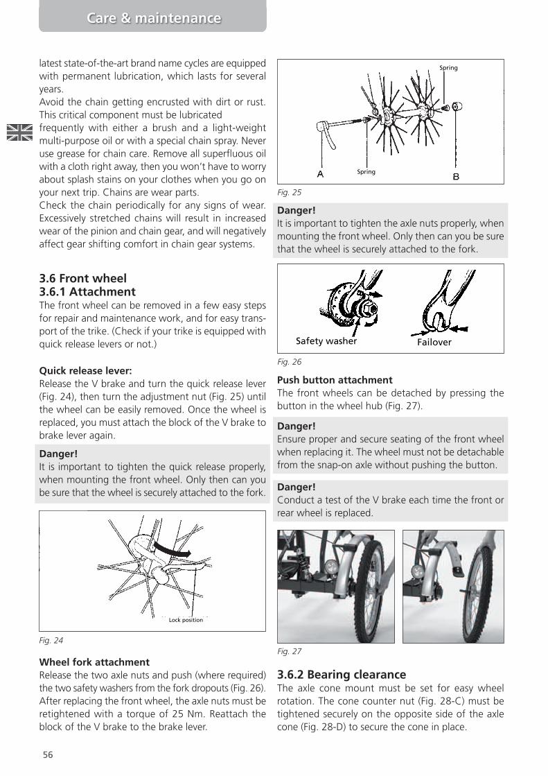
3.6 Front wheel3.6.1 AttachmentThe front wheel can be removed in a few easy stepsfor repair and maintenance work, and for easy trans-port of the trike. (Check if your trike is equipped withquick release levers or not.)
Quick release lever:Release the V brake and turn the quick release lever(Fig. 24), then turn the adjustment nut (Fig. 25) untilthe wheel can be easily removed. Once the wheel isreplaced, you must attach the block of the V brake tobrake lever again.
Danger!It is important to tighten the quick release properly,when mounting the front wheel. Only then can yoube sure that the wheel is securely attached to the fork.
Wheel fork attachmentRelease the two axle nuts and push (where required)the two safety washers from the fork dropouts (Fig. 26).After replacing the front wheel, the axle nuts must beretightened with a torque of 25 Nm. Reattach theblock of the V brake to the brake lever.
Danger!It is important to tighten the axle nuts properly, whenmounting the front wheel. Only then can you be surethat the wheel is securely attached to the fork.
Push button attachmentThe front wheels can be detached by pressing thebutton in the wheel hub (Fig. 27).
Danger!Ensure proper and secure seating of the front wheelwhen replacing it. The wheel must not be detachablefrom the snap-on axle without pushing the button.
Danger!Conduct a test of the V brake each time the front orrear wheel is replaced.
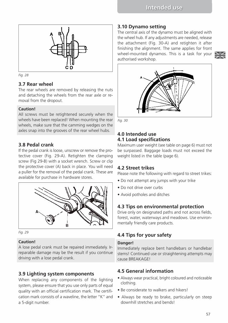
3.6.2 Bearing clearanceThe axle cone mount must be set for easy wheelrotation. The cone counter nut (Fig. 28-C) must betightened securely on the opposite side of the axlecone (Fig. 28-D) to secure the cone in place.
Fig. 24
Spring
Spring
Fig. 25
Fig. 26
FailoverSafety washer
Fig. 27
Spring
Lock position
57
Intended use
3.7 Rear wheelThe rear wheels are removed by releasing the nutsand detaching the wheels from the rear axle or re-moval from the dropout.
Caution!All screws must be retightened securely when thewheels have been replaced! When mounting the rearwheels, make sure that the camming wedges on theaxles snap into the grooves of the rear wheel hubs.
3.8 Pedal crankIf the pedal crank is loose, unscrew or remove the pro-tective cover (Fig. 29-A). Retighten the clampingscrew (Fig 29-B) with a socket wrench. Screw or clipthe protective cover (A) back in place. You will needa puller for the removal of the pedal crank. These areavailable for purchase in hardware stores.
Caution!A lose pedal crank must be repaired immediately. Ir-reparable damage may be the result if you continuedriving with a lose pedal crank.
3.9 Lighting system componentsWhen replacing any components of the lightingsystem, please ensure that you use only parts of equalquality with an of\cial certi\cation mark. The certi\-cation mark consists of a waveline, the letter “K” anda 5-digit number.
3.10 Dynamo settingThe central axis of the dynamo must be aligned withthe wheel hub. If any adjustments are needed, releasethe attachment (Fig. 30-A) and retighten it after\nishing the alignment. The same applies for frontwheel-mounted dynamos. This is a task for yourauthorised workshop.
4.0 Intended use4.1 Load speciOcationsMaximum user weight (see table on page 6) must notbe surpassed. Baggage loads must not exceed theweight listed in the table (page 6).
4.2 Street trikesPlease note the following with regard to street trikes:
• Do not attempt any jumps with your trike
• Do not drive over curbs
• Avoid potholes and ditches
4.3 Tips on environmental protectionDrive only on designated paths and not across \elds,forest, water, waterways and meadows. Use environ-mentally friendly care products.
4.4 Tips for your safety
Danger!Immediately replace bent handlebars or handlebarstems! Continued use or straightening attempts maycause BREAKAGE!
4.5 General information• Always wear practical, bright coloured and noticeableclothing.
• Be considerate to walkers and hikers!
• Always be ready to brake, particularly on steepdownhill stretches and bends!
Fig. 28
Fig. 29
Fig. 30
58
• Do not suspend any loads from the handlebars, asthis will impede driving safety.
• A hub brake (drum brake) may only be retro\tted ifthe fork is marked with an “N”.
• Periodically check the attachments of the pedalcranks and pedals.
• For your safety we recommend always wearing ahelmet when driving. The quality of the helmet isvery important. It should comply at least withlegal recommendations and requirements (relevantstandard: EN 1078 or ANSI).
Danger!On wet roads, the braking distance increases signi\-cantly. You should therefore always moderate yourspeed so that you can always stop in time whenneeded.
Danger!If you leave your cycle standing in direct sunlight, thesaddle, handlebars and other parts of your vehicle canheat up considerably within a short space of time.You can burn yourself!
4.6 Road trafOcWhat do I have to think of in trafOc?Your answer is de\ned in paragraph 1 of the GermanRoad Traf\c Act (StVZO): Each traf\c participant onpublic roads is required to behave in a manner thatdoes not endanger, encumber or inconvenience anyother participant unless dictated by circumstance.
As a cyclist, you are subject to the following rules:
• Extend your arm in the relevant direction ahead oftime, before turning off: check behind you to seethat no other vehicle is close behind you! If turningoff to the left, align yourself with traf\c towards thecentre of the road and navigate the crossing with awide arc. When turning right, take the turn as nar-rowly as possible.
• Always comply with the hand signals of traf\c war-dens and observe traf\c lights. The hand signals ofa traf\c warden supercede all other traf\c signals,including traf\c lights.
• It is not courageous to drive free-handed or whilehanging on to another vehicle - such behaviour islife threatening.
• Similarly, cycling side by side is not permitted. You don’tonly endanger yourself, but other traf\c participantsas well.
• Make sure that your vehicle complies with legalrequirements.
• Only drive roadworthy vehicles.
• Don’t cycle with earphones as they will prevent youfrom hearing warning signals.
• Check brakes, lights and bell for proper functionbefore each trip.
The following components are required for streetcycles in accordance with the Road TrafOc Act:
• Two independently functioning brakes
• A loud sounding bell
• Headlamp, tail light with re]ector, large-area re-]ector at the rear, pedal re]ectors, 2 yellow spokesre]ectors per wheel or white re]ective rings, as wellas a frontal re]ector in a type-approved design.
• A bicycle trailer may only be used on cycles with asturdy frame and fork construction. Additionallyimportant are robust trike brakes at the front andback. The user must keep in mind that thedriving behaviour of a vehicle with a loaded traileris signi\cantly different from that of a trike withouttrailer.
• Trailer transport of persons over 7 years of age and 22kg in weight is strictly prohibited.
Danger!The driver faces challenges speci\cally when starting,in curves, while braking and on slopes.
• Children under the age of 7 may only be carried onthe trike by persons over the age of 16.
• Children must only be transported with an appro-priate child seat. Use only safety-certi\ed child seatsfor cycles. make sure to read and comply with theoperating instructions supplied by the child seatmanufacturer.
• Only use type-approved carriers for transportingyour trike with your car. Make sure that the trike isproperly and securely fastened, and that it causes noimproper stresses due to insuf\cient load distributionduring transport. Any lose parts must be removedto prevent any danger for other traf\c participants.
4.7 LiabilityStreet cycles are designed and equipped for use onpublic roads and paved paths. All relevant safetyequipment provided by the manufacturer must beperiodically checked by the user and repaired or re-placed as needed. The manufacturer accepts no liability
Intended use

59
for any other use of the vehicle and/or for non-compliance with safety-related instructions includedin this manual and any resulting damage. That appliesspeci\cally for the use of the trike in offroad conditions,when overloaded (see technical data), and if faults ofor damages to the trike’s components have not beenrecti\ed.
Intended use includes compliance with the instructionsand conditions provided by the manufacturer in termsof operation, maintenance and service. Trikes mustnot be retro\tted with any components or modi\ed ifthese changes may result in any hazard.
Caution!Any modi\cations done by the user will cancel man-ufacturer liability.
4.8 Warranty informationGeneral legal requirements apply.
5.0 Power assist systems
5.1 Basic information onpower assist systems
What is a power assist system?A power assist system will make cycling easier, as yourown pedaling power is supplemented. Comparedwith regular cycles, you will only need about half thepower. Cycling therefore becomes a comfortable andeasy pastime, as an “invisible helper” is pushing youforward.
Two systems can be supplied:Motion sensor:The power assist system is activated only if the motionsensor (integrated in the pedal crank area) detectspedaling. You won’t have to put any effort into pedaling,as it is only important for the sensor to detect therotation of the crank. You can then control the levelof assistance and therefore also the speed by twistingthe “gas” throttle. These vehicles are equipped witha start-up help up to 6 km/h to help you get started.
Power sensor:The power sensor, which is usually connected to thecrank arms, will register the power used on the pedalsby the rider. A selection via the display adds either equalpower (Normal mode), half power (Eco mode) or doublethe power (Sport mode) from the electromotor to yourown efforts. Most of these systems are not equippedwith a start-up help, as they don’t have a twist throttle.
Individuals that don’t have enough power to push thepedals due to some physical limitation (e.g. on an in-cline), will not be able to utilise the power assist sys-tem.
Under what conditions is it most useful to havea power assist system?On inclines, with headwind, when transporting loads,or at night, when lighting conditions are impaired, orgenerally under conditions where regular cycles requiresigni\cant power reserves for traveling.
What is the power source on an e-cycle?E-cycles use a rechargeable Lilon battery, which, how-ever, does not automatically reload during cycling.Charging is easy, however - simply plug the chargerinto any regular household socket.
Do the batteries last forever?No. All batteries have a limited lifespan. You shouldreplace the battery when you start noticing that thecycling reach achieved with a full battery decreasessigni\cantly. Operating conditions, temperaturesand/or the charging process signi\cantly in]uence thelifespan of the battery. (Please read the attached manualprovided by the manufacturer.)(Battery replacements are not free of charge.)
Note:The timing for battery replacement is not part of theregular product warranty; please note the separatewarranty conditions supplied.
Can an e-cycle overcome any kind of incline?A certain percentage of the drive power in an e-cyclemust be provided by the rider. The rate of incline thee-cycle can handle therefore depends on your ownphysical power. Some inclines may be too much to copewith, even with the power assist system on an e-cycle.
Note:Detailed information on the various power assist sys-tems are provided in the documentation provided bythe relevant manufacturer, which is supplied separatelyin the appendix.
Power assist systems

60
Exploded drawing
1L, 1S
2
3L, 3S
4
5
6
7
8
91011
1213
14
15
16
1718
18
18
18
19L
19R
20
22
2324
25 2728
29
30
38
37
39
40
3336
36
33
33
26
3132
Part ScooterTrike ItemNo: 16"-20"1L 10-000-00068 “L” SCT frame Scooter “L”1S 10-000-00068 “S” SCT frame Scooter “S”2 10-000-00070 SCT rocker Scooter3L 10-000-00069 “L” SCT handlebar stem Scooter “L”3S 10-000-00069 “S” SCT handlebar stem Scooter “S”4 10-000-00067 SCT fork 16" rigid5 10-080-00049 SCT seat frame 2-part, incl. back rest6 10-080-00041 SCT seat cushion7 10-080-00045 SCT seat cover8 10-040-00023 SCT clamping parts back rest9 10-080-00042 SCT seat rail10 10-080-00043 SCT Rail Stone for seat rail11 10-080-00044 SCT quick release12 10-030-00026 SCT baggage rack13 09/0035.31 basket brace14 10-060-00020 Mud guard brace15 10-030-00024 Basket16 10-000-00071 SCT spring element17 10-070-00007 Differential gearing18 10-070-00005 Deep groove ball bearing 600319L 10-070-00035 SCT axle short left 312.1 mm19R 10-070-00036 SCT axle long right 382.2 mm20 10-010-00061 SCT gear hub 7 gear RFN w. pinion22 10-070-00038 SCT chain tensioner23 10-000-00072 SCT slide bush for rocker bearing24 10-000-XXXXX Rocker bearing 132x20x1625 10-000-00073 SCT threaded rod26 10-000-XXXXX Glider 3227 10-070-00037 SCT crank set 38Z with double protection28 10-070-00029 Chain protection tube29 10-070-XXXXX Spacer plate30 10-070-XXXXX Webbing for chain protection tube31 10-040-00035 SCT handlebar black32 10-040-00036 SCT handlebar adjustment unit33 10-040-00037 SCT Spacer 3-part36 10-040-00038 SCT control set 1 1/8" Ahead37 11-060-XXXXX Impeller front 16" aluminium hollow chamber black hub dynamo38 10-060-00101 SCT mud guard 16" front black39 11-060-XXXXX Impeller rear 20" aluminium hollow chamber black40 10-060-00100 SCT mud guard 20" rear black
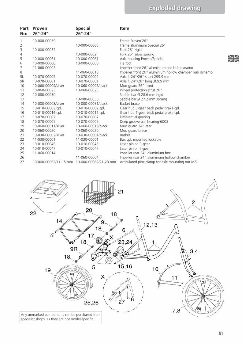
Any unmarked components can bepurchased from specialist shops, asthey are not model-speci\c!
61
Exploded drawing
Part Proven Special ItemNo: 26"-24" 26"-24"
1 10-000-00059 Frame Proven 26"2 10-000-00063 Frame aluminium Special 26"3 10-000-00052 Fork 26" rigid4 10-000-0002 Fork 26" silver sprung5 10-000-00061 10-000-00061 Axle housing Proven/Special6 10-000-00060 10-000-00060 Tie rod7 11-060-00002 Impeller front 26" aluminium box hub dynamo8 11-060-00010 Impeller front 26" aluminium hollow chamber hub dynamo9L 10-070-00002 10-070-00002 Axle f. 24"/26" short 299.9 mm9R 10-070-00001 10-070-00001 Axle f. 24"/26" long 369.9 mm10 10-060-00009/silver 10-060-00008/black Mud guard 26" front11 10-060-00023 10-060-00023 Wheel protection strut 26"12 10-080-00030 Saddle bar Ø 28.6 mm rigid13 10-080-00036 Saddle bar Ø 27.2 mm sprung14 10-000-00008/silver 10-000-00051/black Basket brace15 10-010-00002 cpl. 10-010-00002 cpl. Gear hub 3-gear back pedal brake cpl.16 10-010-00016 cpl. 10-010-00016 cpl. Gear hub 7-gear back pedal brake cpl.17 10-070-00007 10-070-00007 Differential gearing18 10-070-00005 10-070-00005 Deep groove ball bearing 600319 10-060-00011/silver 10-060-00010/black Mud guard 24" rear20 10-060-00020 10-060-00020 Mud guard brace21 10-030-00002/silver 10-030-00001/black Basket22 11-030-00001 11-030-00001 Box cpl. mounted lockable23 10-010-00045 10-010-00045 Laser pinion 3-gear24 10-010-00047 10-010-00047 Laser pinion 7-gear25 11-060-00014 Impeller rear 24" aluminium box26 11-060-00004 Impeller rear 24" aluminium hollow chamber27 10-000-00062/11-15 mm 10-000-00062/21-23 mm Articulated pipe clamp for axle mounting nut M8
18
18
18
18
9R
9L
17
1
2
3,4
5
6
6
7,8
10
11
12,1314
15,1619
20
21
22
23,24
25,26 27
X
X
Any unmarked components can be purchased fromspecialist shops, as they are not model-speci\c!
62
9L
9R
1817
18
18
18
1
2
3,4
5
6
7,8
16
10,11
12,13
14
1519
20
21
22
23
25,26
27L28
3031
X
X
29 6
32
3334 35,36
24
24
37,38 39
27R
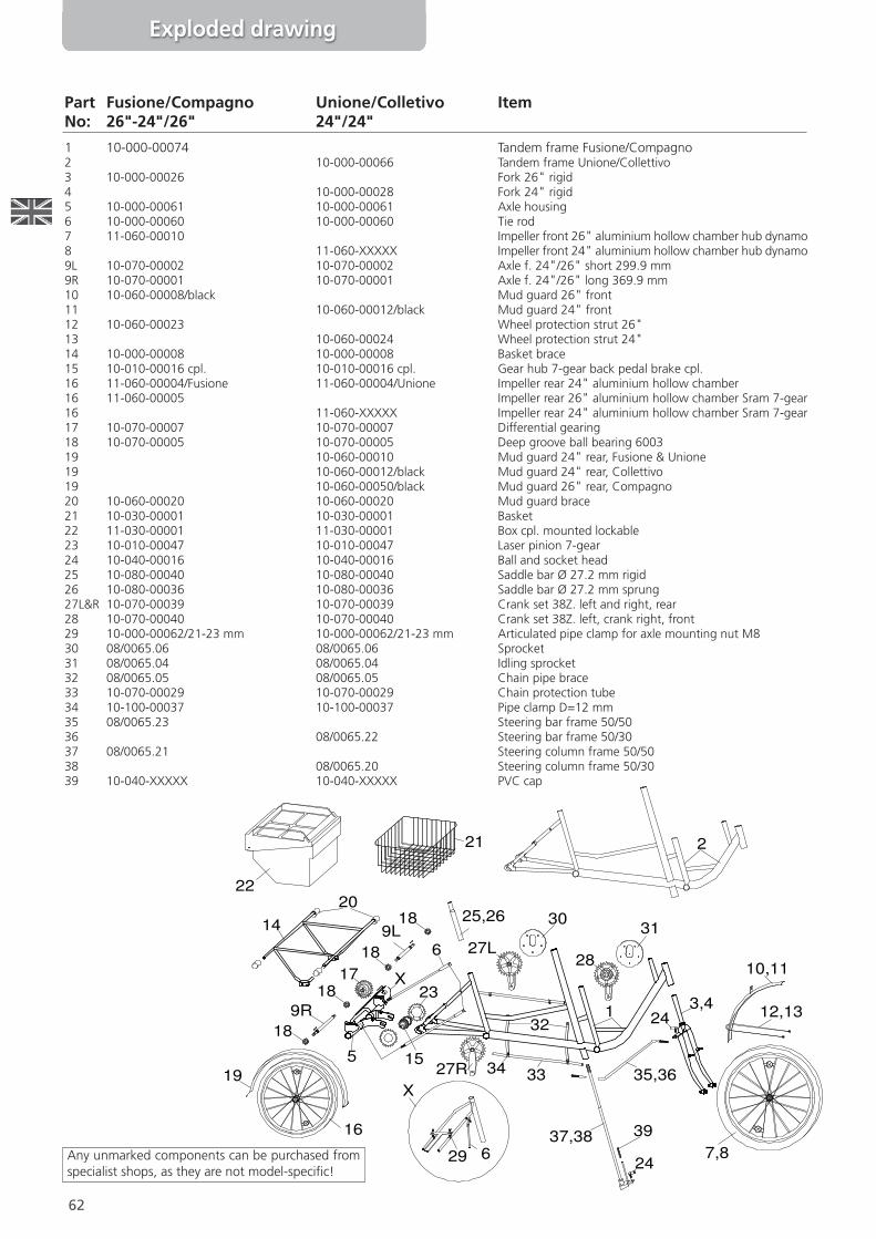
Part Fusione/Compagno Unione/Colletivo ItemNo: 26"-24"/26" 24"/24"
1 10-000-00074 Tandem frame Fusione/Compagno2 10-000-00066 Tandem frame Unione/Collettivo3 10-000-00026 Fork 26" rigid4 10-000-00028 Fork 24" rigid5 10-000-00061 10-000-00061 Axle housing6 10-000-00060 10-000-00060 Tie rod7 11-060-00010 Impeller front 26" aluminium hollow chamber hub dynamo8 11-060-XXXXX Impeller front 24" aluminium hollow chamber hub dynamo9L 10-070-00002 10-070-00002 Axle f. 24"/26" short 299.9 mm9R 10-070-00001 10-070-00001 Axle f. 24"/26" long 369.9 mm10 10-060-00008/black Mud guard 26" front11 10-060-00012/black Mud guard 24" front12 10-060-00023 Wheel protection strut 26"13 10-060-00024 Wheel protection strut 24"14 10-000-00008 10-000-00008 Basket brace15 10-010-00016 cpl. 10-010-00016 cpl. Gear hub 7-gear back pedal brake cpl.16 11-060-00004/Fusione 11-060-00004/Unione Impeller rear 24" aluminium hollow chamber16 11-060-00005 Impeller rear 26" aluminium hollow chamber Sram 7-gear16 11-060-XXXXX Impeller rear 24" aluminium hollow chamber Sram 7-gear17 10-070-00007 10-070-00007 Differential gearing18 10-070-00005 10-070-00005 Deep groove ball bearing 600319 10-060-00010 Mud guard 24" rear, Fusione & Unione19 10-060-00012/black Mud guard 24" rear, Collettivo19 10-060-00050/black Mud guard 26" rear, Compagno20 10-060-00020 10-060-00020 Mud guard brace21 10-030-00001 10-030-00001 Basket22 11-030-00001 11-030-00001 Box cpl. mounted lockable23 10-010-00047 10-010-00047 Laser pinion 7-gear24 10-040-00016 10-040-00016 Ball and socket head25 10-080-00040 10-080-00040 Saddle bar Ø 27.2 mm rigid26 10-080-00036 10-080-00036 Saddle bar Ø 27.2 mm sprung27L&R 10-070-00039 10-070-00039 Crank set 38Z. left and right, rear28 10-070-00040 10-070-00040 Crank set 38Z. left, crank right, front29 10-000-00062/21-23 mm 10-000-00062/21-23 mm Articulated pipe clamp for axle mounting nut M830 08/0065.06 08/0065.06 Sprocket31 08/0065.04 08/0065.04 Idling sprocket32 08/0065.05 08/0065.05 Chain pipe brace33 10-070-00029 10-070-00029 Chain protection tube34 10-100-00037 10-100-00037 Pipe clamp D=12 mm35 08/0065.23 Steering bar frame 50/5036 08/0065.22 Steering bar frame 50/3037 08/0065.21 Steering column frame 50/5038 08/0065.20 Steering column frame 50/3039 10-040-XXXXX 10-040-XXXXX PVC cap
Any unmarked components can be purchased fromspecialist shops, as they are not model-speci\c!
Exploded drawing
63
Exploded drawing
9L
9R
2
3
4,5
6
6
7
8
10
11
12,13
1415
16
17,18
1920
20
21
22
24
23
2526
27,28
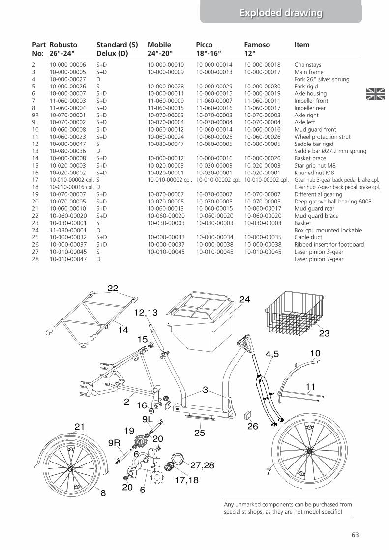
Part Robusto Standard (S) Mobile Picco Famoso ItemNo: 26"-24" Delux (D) 24"-20" 18"-16" 12"
2 10-000-00006 S+D 10-000-00010 10-000-00014 10-000-00018 Chainstays3 10-000-00005 S+D 10-000-00009 10-000-00013 10-000-00017 Main frame4 10-000-00027 D Fork 26" silver sprung5 10-000-00026 S 10-000-00028 10-000-00029 10-000-00030 Fork rigid6 10-000-00007 S+D 10-000-00011 10-000-00015 10-000-00019 Axle housing7 11-060-00003 S+D 11-060-00009 11-060-00007 11-060-00011 Impeller front8 11-060-00004 S+D 11-060-00015 11-060-00016 11-060-00017 Impeller rear9R 10-070-00001 S+D 10-070-00003 10-070-00003 10-070-00003 Axle right9L 10-070-00002 S+D 10-070-00004 10-070-00004 10-070-00004 Axle left10 10-060-00008 S+D 10-060-00012 10-060-00014 10-060-00016 Mud guard front11 10-060-00023 S+D 10-060-00024 10-060-00025 10-060-00026 Wheel protection strut12 10-080-00047 S 10-080-00047 10-080-00005 10-080-00005 Saddle bar rigid13 10-080-00036 D Saddle bar Ø27.2 mm sprung14 10-000-00008 S+D 10-000-00012 10-000-00016 10-000-00020 Basket brace15 10-020-00003 S+D 10-020-00003 10-020-00003 10-020-00003 Star grip nut M816 10-020-00002 S+D 10-020-00001 10-020-00001 10-020-00001 Knurled nut M817 10-010-00002 cpl. S 10-010-00002 cpl. 10-010-00002 cpl. 10-010-00002 cpl. Gear hub 3-gear back pedal brake cpl.18 10-010-00016 cpl. D Gear hub 7-gear back pedal brake cpl.19 10-070-00007 S+D 10-070-00007 10-070-00007 10-070-00007 Differential gearing20 10-070-00005 S+D 10-070-00005 10-070-00005 10-070-00005 Deep groove ball bearing 600321 10-060-00010 S+D 10-060-00013 10-060-00015 10-060-00017 Mud guard rear22 10-060-00020 S+D 10-060-00020 10-060-00020 10-060-00020 Mud guard brace23 10-030-00001 S 10-030-00003 10-030-00003 10-030-00003 Basket24 11-030-00001 D Box cpl. mounted lockable25 10-000-00032 S+D 10-000-00033 10-000-00034 10-000-00035 Cable duct26 10-000-00037 S+D 10-000-00037 10-000-00038 10-000-00038 Ribbed insert for footboard27 10-010-00045 S 10-010-00045 10-010-00045 10-010-00045 Laser pinion 3-gear28 10-010-00047 D Laser pinion 7-gear
Any unmarked components can be purchased fromspecialist shops, as they are not model-speci\c!
64
Any unmarked components can be purchased fromspecialist shops, as they are not model-speci\c!
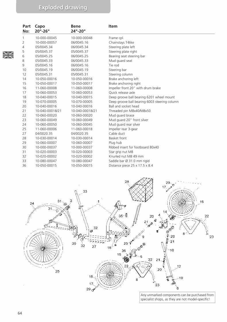
Part Capo Bene ItemNo: 20"-26" 24"-20"
1 10-000-00045 10-000-00048 Frame cpl.2 10-000-00057 06/0045.16 Chainstays T-Bike4 05/0045.34 06/0045.34 Steering plate left5 05/0045.37 05/0045.37 Steering plate right6 05/0045.25 06/0045.25 Bearing seat steering bar8 05/0045.33 06/0045.33 Mud guard seat9 05/0045.16 06/0045.16 Tie rod10 05/0045.19 06/0045.19 Steering bar12 05/0045.31 05/0045.31 Steering column14 10-050-00016 10-050-00016 Brake anchoring left15 10-050-00017 10-050-00017 Brake anchoring right16 11-060-00008 11-060-00008 Impeller front 20" with drum brake17 10-060-00053 10-060-00053 Quick release axle18 10-040-00015 10-040-00015 Deep groove ball bearing 6201 wheel mount19 10-070-00005 10-070-00005 Deep groove ball bearing 6003 steering column20 10-040-00016 10-040-00016 Ball and socket head21 10-040-00018/21 10-040-00018/21 Threaded pin M8x40/M8x5022 10-060-00020 10-060-00020 Mud guard brace23 10-060-00049 10-060-00049 Mud guard 20" front silver24 10-060-00050 10-060-00045 Mud guard rear silver25 11-060-00006 11-060-00018 Impeller rear 3-gear27 04/0020.35 04/0020.35 Cable duct28 10-030-00014 10-030-00014 Basket front29 10-060-00007 10-060-00007 Plug hub30 10-000-00037 10-000-00037 Ribbed insert for footboard 80x4031 10-020-00003 10-020-00003 Star grip nut M832 10-020-00002 10-020-00002 Knurled nut M8 49 mm33 10-080-00047 10-080-00047 Saddle bar Ø 31.0 mm rigid36 10-050-00015 10-050-00015 Distance piece 25 x 17.5 x 8.4
Exploded drawing
65
Exploded drawing
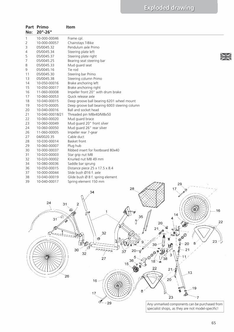
Any unmarked components can be purchased fromspecialist shops, as they are not model-speci\c!
Part Primo ItemNo: 20"-26"1 10-000-00046 Frame cpl.2 10-000-00057 Chainstays T-Bike3 05/0045.32 Pendulum axle Primo4 05/0045.34 Steering plate left5 05/0045.37 Steering plate right7 05/0045.25 Bearing seat steering bar8 05/0045.33 Mud guard seat9 05/0045.16 Tie rod11 05/0045.30 Steering bar Primo13 05/0045.38 Steering column Primo14 10-050-00016 Brake anchoring left15 10-050-00017 Brake anchoring right16 11-060-00008 Impeller front 20" with drum brake17 10-060-00053 Quick release axle18 10-040-00015 Deep groove ball bearing 6201 wheel mount19 10-070-00005 Deep groove ball bearing 6003 steering column20 10-040-00016 Ball and socket head21 10-040-00018/21 Threaded pin M8x40/M8x5022 10-060-00020 Mud guard brace23 10-060-00049 Mud guard 20" front silver24 10-060-00050 Mud guard 26" rear silver26 11-060-00005 Impeller rear 7-gear27 04/0020.35 Cable duct28 10-030-00014 Basket front29 10-060-00007 Plug hub30 10-000-00037 Ribbed insert for footboard 80x4031 10-020-00003 Star grip nut M832 10-020-00002 Knurled nut M8 49 mm34 10-080-00036 Saddle bar sprung36 10-050-00015 Distance piece 25 x 17.5 x 8.437 10-000-00044 Slide bush Ø16 f. axle38 10-040-00019 Glide bush Ø 8 f. spring element39 10-040-00017 Spring element 150 mm
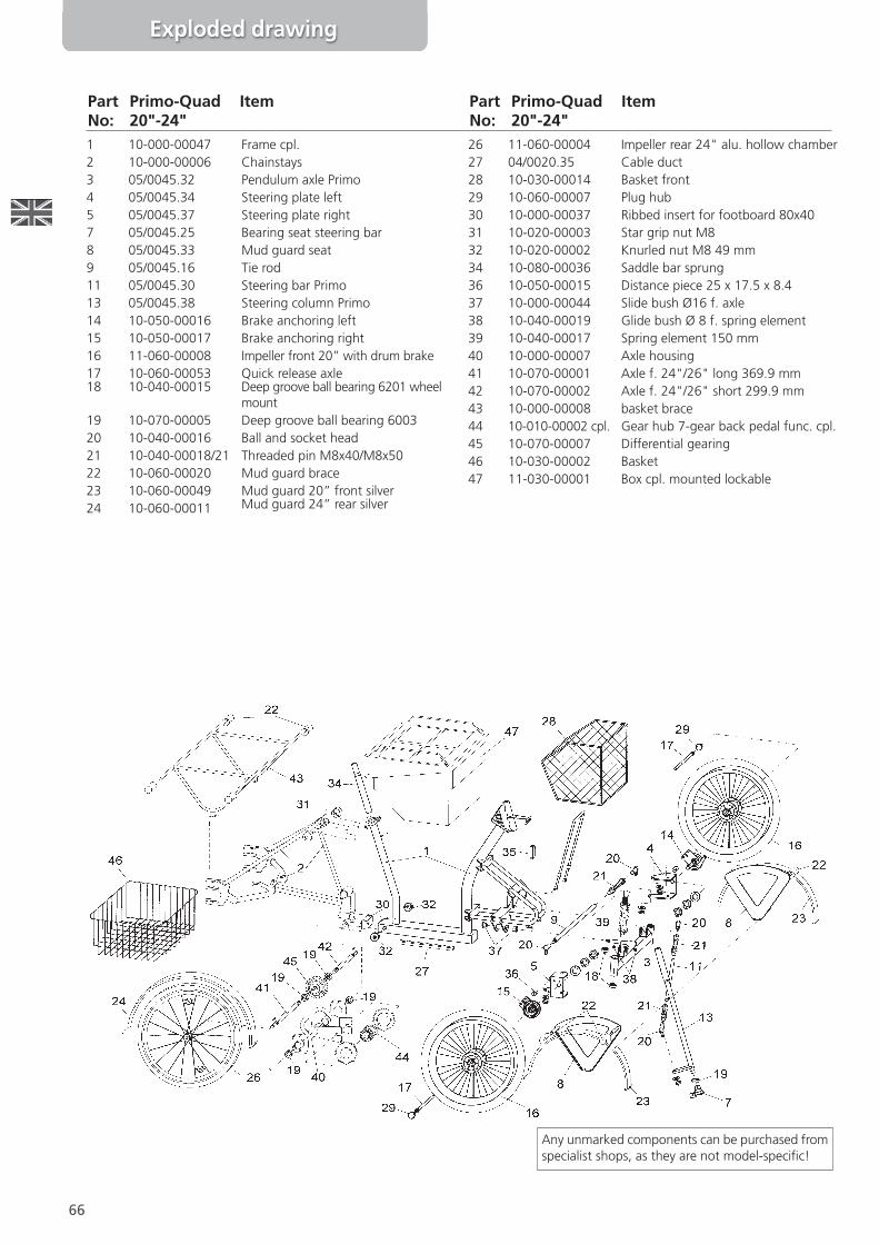
1 10-000-00047 Frame cpl.2 10-000-00006 Chainstays3 05/0045.32 Pendulum axle Primo4 05/0045.34 Steering plate left5 05/0045.37 Steering plate right7 05/0045.25 Bearing seat steering bar8 05/0045.33 Mud guard seat9 05/0045.16 Tie rod11 05/0045.30 Steering bar Primo13 05/0045.38 Steering column Primo14 10-050-00016 Brake anchoring left15 10-050-00017 Brake anchoring right16 11-060-00008 Impeller front 20” with drum brake17 10-060-00053 Quick release axle18 10-040-00015 Deep groove ball bearing 6201 wheel
mount19 10-070-00005 Deep groove ball bearing 600320 10-040-00016 Ball and socket head21 10-040-00018/21 Threaded pin M8x40/M8x5022 10-060-00020 Mud guard brace23 10-060-00049 Mud guard 20” front silver24 10-060-00011 Mud guard 24” rear silver
26 11-060-00004 Impeller rear 24" alu. hollow chamber27 04/0020.35 Cable duct28 10-030-00014 Basket front29 10-060-00007 Plug hub30 10-000-00037 Ribbed insert for footboard 80x4031 10-020-00003 Star grip nut M832 10-020-00002 Knurled nut M8 49 mm34 10-080-00036 Saddle bar sprung36 10-050-00015 Distance piece 25 x 17.5 x 8.437 10-000-00044 Slide bush Ø16 f. axle38 10-040-00019 Glide bush Ø 8 f. spring element39 10-040-00017 Spring element 150 mm40 10-000-00007 Axle housing41 10-070-00001 Axle f. 24"/26" long 369.9 mm42 10-070-00002 Axle f. 24"/26" short 299.9 mm43 10-000-00008 basket brace44 10-010-00002 cpl. Gear hub 7-gear back pedal func. cpl.45 10-070-00007 Differential gearing46 10-030-00002 Basket47 11-030-00001 Box cpl. mounted lockable
66
Any unmarked components can be purchased fromspecialist shops, as they are not model-speci\c!
Part Primo-Quad ItemNo: 20"-24"
Part Primo-Quad ItemNo: 20"-24"
Exploded drawing
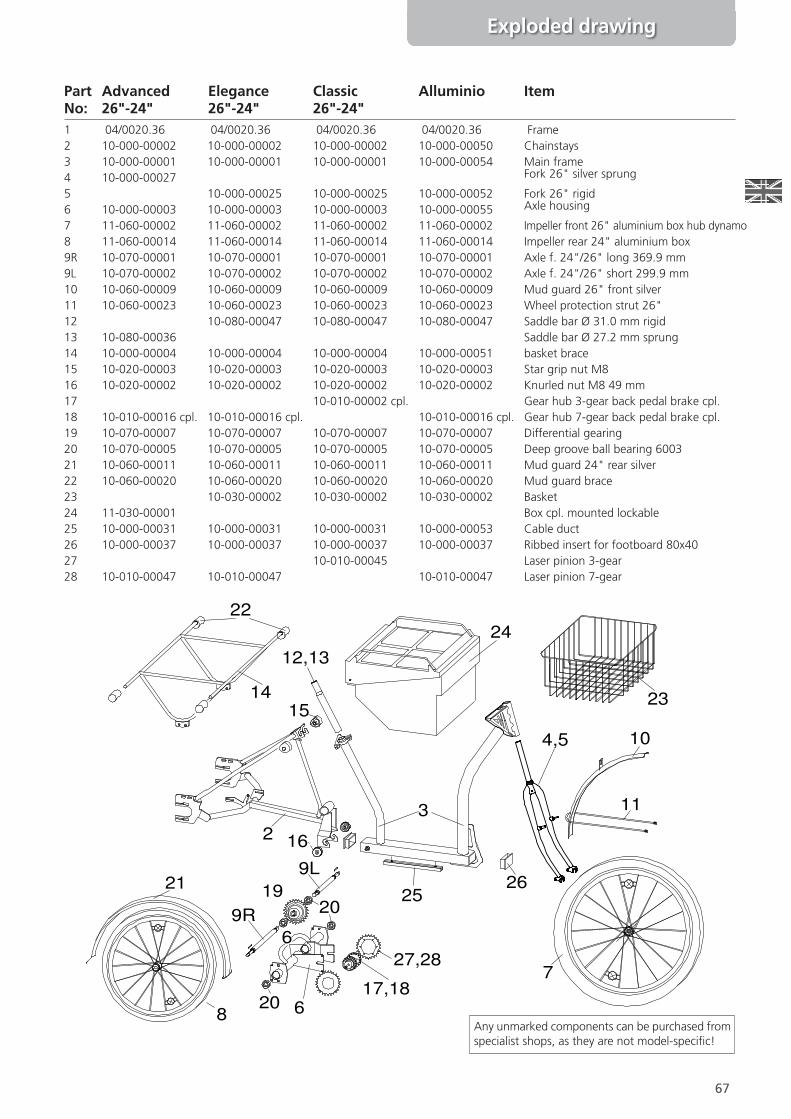
1 04/0020.36 04/0020.36 04/0020.36 04/0020.36 Frame2 10-000-00002 10-000-00002 10-000-00002 10-000-00050 Chainstays3 10-000-00001 10-000-00001 10-000-00001 10-000-00054 Main frame4 10-000-00027 Fork 26" silver sprung
5 10-000-00025 10-000-00025 10-000-00052 Fork 26" rigid6 10-000-00003 10-000-00003 10-000-00003 10-000-00055 Axle housing
7 11-060-00002 11-060-00002 11-060-00002 11-060-00002 Impeller front 26" aluminium box hub dynamo8 11-060-00014 11-060-00014 11-060-00014 11-060-00014 Impeller rear 24" aluminium box9R 10-070-00001 10-070-00001 10-070-00001 10-070-00001 Axle f. 24"/26" long 369.9 mm9L 10-070-00002 10-070-00002 10-070-00002 10-070-00002 Axle f. 24"/26" short 299.9 mm10 10-060-00009 10-060-00009 10-060-00009 10-060-00009 Mud guard 26" front silver11 10-060-00023 10-060-00023 10-060-00023 10-060-00023 Wheel protection strut 26"12 10-080-00047 10-080-00047 10-080-00047 Saddle bar Ø 31.0 mm rigid13 10-080-00036 Saddle bar Ø 27.2 mm sprung14 10-000-00004 10-000-00004 10-000-00004 10-000-00051 basket brace15 10-020-00003 10-020-00003 10-020-00003 10-020-00003 Star grip nut M816 10-020-00002 10-020-00002 10-020-00002 10-020-00002 Knurled nut M8 49 mm17 10-010-00002 cpl. Gear hub 3-gear back pedal brake cpl.18 10-010-00016 cpl. 10-010-00016 cpl. 10-010-00016 cpl. Gear hub 7-gear back pedal brake cpl.19 10-070-00007 10-070-00007 10-070-00007 10-070-00007 Differential gearing20 10-070-00005 10-070-00005 10-070-00005 10-070-00005 Deep groove ball bearing 600321 10-060-00011 10-060-00011 10-060-00011 10-060-00011 Mud guard 24" rear silver22 10-060-00020 10-060-00020 10-060-00020 10-060-00020 Mud guard brace23 10-030-00002 10-030-00002 10-030-00002 Basket24 11-030-00001 Box cpl. mounted lockable25 10-000-00031 10-000-00031 10-000-00031 10-000-00053 Cable duct26 10-000-00037 10-000-00037 10-000-00037 10-000-00037 Ribbed insert for footboard 80x4027 10-010-00045 Laser pinion 3-gear28 10-010-00047 10-010-00047 10-010-00047 Laser pinion 7-gear
67
Exploded drawing
Part Advanced Elegance Classic Alluminio ItemNo: 26"-24" 26"-24" 26"-24"
9L
9R
2
3
4,5
6
6
7
8
10
11
12,13
1415
16
17,18
1920
20
21
22
24
23
2526
27,28
Any unmarked components can be purchased fromspecialist shops, as they are not model-speci\c!
68
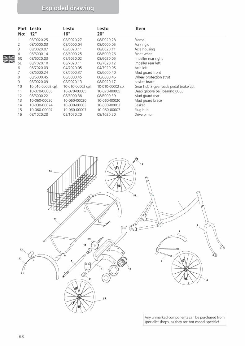
Part Lesto Lesto Lesto ItemNo: 12" 16" 20"
14
9
13
12
11
6
16
11
10
15
5 L
5 R
4
2
1
3
7
8
Any unmarked components can be purchased fromspecialist shops, as they are not model-speci\c!
Exploded drawing
1 08/0020.25 08/0020.27 08/0020.28 Frame2 08/0000.03 08/0000.04 08/0000.05 Fork rigid3 08/0020.07 08/0020.11 08/0020.11 Axle housing4 08/6000.14 08/6000.25 08/6000.26 Front wheel5R 08/6020.03 08/6020.02 08/6020.05 Impeller rear right5L 08/7020.10 08/7020.11 08/7020.12 Impeller rear left6 08/7020.03 04/7020.05 04/7020.05 Axle left7 08/6000.24 08/6000.37 08/6000.40 Mud guard front8 08/6000.45 08/6000.45 08/6000.45 Wheel protection strut9 08/0020.09 08/0020.13 08/0020.17 basket brace10 10-010-00002 cpl. 10-010-00002 cpl. 10-010-00002 cpl. Gear hub 3-gear back pedal brake cpl.11 10-070-00005 10-070-00005 10-070-00005 Deep groove ball bearing 600312 08/6000.22 08/6000.38 08/6000.39 Mud guard rear13 10-060-00020 10-060-00020 10-060-00020 Mud guard brace14 10-030-00024 10-030-00003 10-030-00003 Basket15 10-060-00007 10-060-00007 10-060-00007 Plug hub16 08/1020.20 08/1020.20 08/1020.20 Drive pinion
69
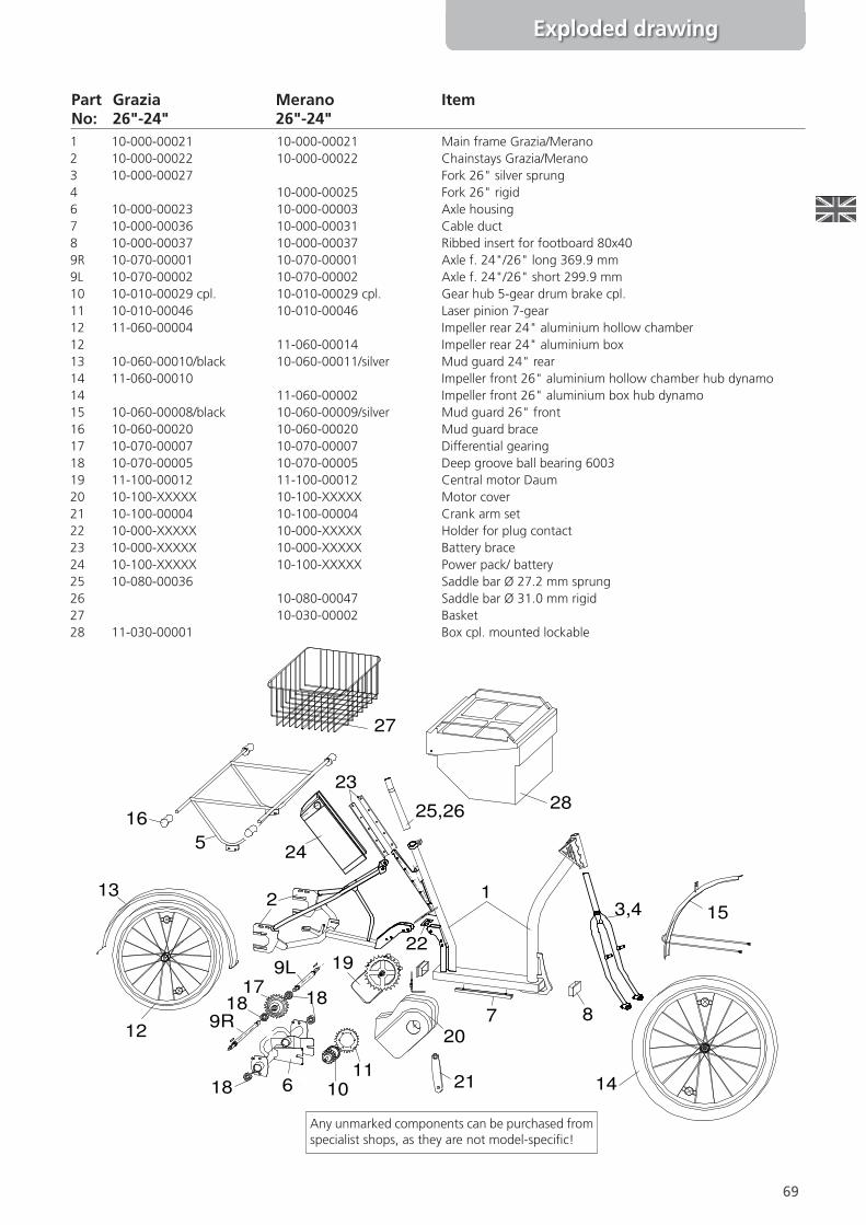
Part Grazia Merano ItemNo: 26"-24" 26"-24"
123,4
5
6
7 8
9L
9R
1718 18
18 1011
12
13
14
15
16
19
20
21
22
23
24
25,26
27
28
Any unmarked components can be purchased fromspecialist shops, as they are not model-speci\c!
1 10-000-00021 10-000-00021 Main frame Grazia/Merano2 10-000-00022 10-000-00022 Chainstays Grazia/Merano3 10-000-00027 Fork 26" silver sprung4 10-000-00025 Fork 26" rigid6 10-000-00023 10-000-00003 Axle housing7 10-000-00036 10-000-00031 Cable duct8 10-000-00037 10-000-00037 Ribbed insert for footboard 80x409R 10-070-00001 10-070-00001 Axle f. 24"/26" long 369.9 mm9L 10-070-00002 10-070-00002 Axle f. 24"/26" short 299.9 mm10 10-010-00029 cpl. 10-010-00029 cpl. Gear hub 5-gear drum brake cpl.11 10-010-00046 10-010-00046 Laser pinion 7-gear12 11-060-00004 Impeller rear 24" aluminium hollow chamber12 11-060-00014 Impeller rear 24" aluminium box13 10-060-00010/black 10-060-00011/silver Mud guard 24" rear14 11-060-00010 Impeller front 26" aluminium hollow chamber hub dynamo14 11-060-00002 Impeller front 26" aluminium box hub dynamo15 10-060-00008/black 10-060-00009/silver Mud guard 26" front16 10-060-00020 10-060-00020 Mud guard brace17 10-070-00007 10-070-00007 Differential gearing18 10-070-00005 10-070-00005 Deep groove ball bearing 600319 11-100-00012 11-100-00012 Central motor Daum20 10-100-XXXXX 10-100-XXXXX Motor cover21 10-100-00004 10-100-00004 Crank arm set22 10-000-XXXXX 10-000-XXXXX Holder for plug contact23 10-000-XXXXX 10-000-XXXXX Battery brace24 10-100-XXXXX 10-100-XXXXX Power pack/ battery25 10-080-00036 Saddle bar Ø 27.2 mm sprung26 10-080-00047 Saddle bar Ø 31.0 mm rigid27 10-030-00002 Basket28 11-030-00001 Box cpl. mounted lockable
Exploded drawing
70
Exploded drawing
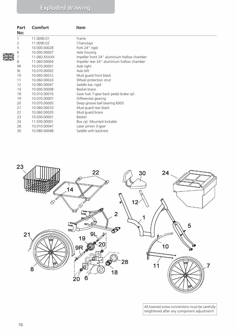
Part Comfort ItemNo:1 11.0090.01 Frame2 11.0090.02 Chainstays5 10.000.00028 Fork 24" rigid6 10.000.00007 Axle housing7 11.060.XXXXX Impeller front 24" aluminium hollow chamber8 11.060.00004 Impeller rear 24" aluminium hollow chamber9R 10.070.00001 Axle right9L 10.070.00002 Axle left10 10.060.00012 Mud guard front black11 10.060.00024 Wheel protection strut12 10.080.00047 Saddle bar, rigid14 10.000.00008 Basket brace18 10.010.00016 Gear hub 7-gear back pedal brake cpl.19 10.070.00007 Differential gearing20 10.070.00005 Deep groove ball bearing 600321 10.060.00010 Mud guard rear black22 10.060.00020 Mud guard brace23 10.030.00001 Basket24 11.030.00001 Box cpl. Mounted lockable28 10.010.00047 Laser pinion 3-gear30 10.080.00048 Saddle with backrest
All losened screw connections must be carefullyretightened after any component adjustment!
71
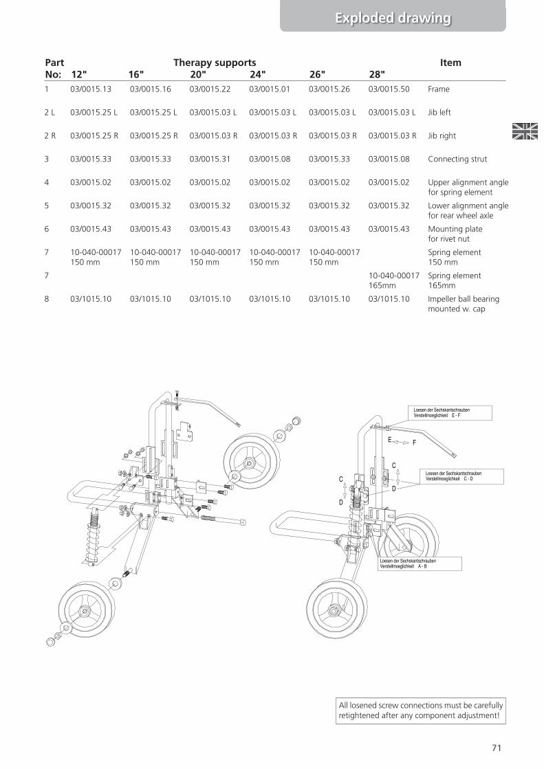
All losened screw connections must be carefullyretightened after any component adjustment!
1 03/0015.13 03/0015.16 03/0015.22 03/0015.01 03/0015.26 03/0015.50 Frame
2 L 03/0015.25 L 03/0015.25 L 03/0015.03 L 03/0015.03 L 03/0015.03 L 03/0015.03 L Jib left
2 R 03/0015.25 R 03/0015.25 R 03/0015.03 R 03/0015.03 R 03/0015.03 R 03/0015.03 R Jib right
3 03/0015.33 03/0015.33 03/0015.31 03/0015.08 03/0015.33 03/0015.08 Connecting strut
4 03/0015.02 03/0015.02 03/0015.02 03/0015.02 03/0015.02 03/0015.02 Upper alignment anglefor spring element
5 03/0015.32 03/0015.32 03/0015.32 03/0015.32 03/0015.32 03/0015.32 Lower alignment anglefor rear wheel axle
6 03/0015.43 03/0015.43 03/0015.43 03/0015.43 03/0015.43 03/0015.43 Mounting platefor rivet nut
7 10-040-00017150 mm
10-040-00017150 mm
10-040-00017150 mm
10-040-00017150 mm
10-040-00017150 mm
Spring element150 mm
7 10-040-00017165mm
Spring element165mm
8 03/1015.10 03/1015.10 03/1015.10 03/1015.10 03/1015.10 03/1015.10 Impeller ball bearingmounted w. cap
Part Therapy supports ItemNo: 12" 16" 20" 24" 26" 28"
Exploded drawing
C
D
C
D
Loesen der SechskantschraubenVerstellmoeglichkeit A - B
Loesen der SechskantschraubenVerstellmoeglichkeit C - D
Loesen der SechskantschraubenVerstellmoeglichkeit E - F
B
A
E F
72
Handover certificate trade
Name
Street
ZIP/City
Street No.
Company name
Street
ZIP/City
Telephone
Street No.
Details of dealership:
Customer details:
Product Name
Brand Delivery Date
Date Signature
ConOrmation
❑ I have thoroughly checked the above named product.
❑ The delivery was complete and without any apparent damage.
❑ Comments:
❑ I have received the operating manual including service and maintenance instructions,and I have received an oral introduction to the product.
❑ I am aware that a seller’s warranty exists for product faultsonly. For damage due to wear, resulting from the use of the product,no warranty is extended, speci\cally for wear attributable to “normal use”.

73
7.0 Maintenance logPeriodic maintenance by an authorised workshop is prerequisite to successful warranty claims. The maintenanceintervals should not surpass 6 months in order to guarantee traf\c safety and a technically sound vehicle!
Have all maintenance work documented here:
Date SignatureStamp/ Authorised workshop
Date SignatureStamp/ Authorised workshop
Date SignatureStamp/ Authorised workshop
Date SignatureStamp/ Authorised workshop
Date SignatureStamp/ Authorised workshop
Date SignatureStamp/ Authorised workshop
Date SignatureStamp/ Authorised workshop
Maintenance log
74
Bicycle Passport
Bicycle PassportSome good adviceNote down the speci\c data of your cycle immediately after purchase.You will then be able to provide an accurate description of you vehicle, should it be stolen. This point is ofparticular importance if you will be making an insurance claim.
Register your vehicle with the police if possible.
Name
Street
ZIP/City
Telephone
Date of Purchase Purchase Price
Street No.
Frame Colour
Mud Guard Colour
Tires (brand and size)
Hub Gearing
Number of Gears
Accessories
Special Features
Frame Number (to be found on the pedal crank housing)
Vehicle Description
Model:

75
In compliance with Appendix VII of the Directive 93/42/EEC on Medical Products
EC DECLARATION OF CONFORMITY
PFIFF Vertriebs GmbHI/ We
Name and address of the manufacturer
Wilhelmstraße 49
D-49610 Quakenbrück
declare in sole responsibility that the products:Therapy Trikes
Model Bene Model CapoModel Primo Model Primo-QuadModel Famoso Model GraziaModel Lesto Model MobileModel Picco Model Robusto DeluxeModel Robusto Standard
comply with the basic requirements of Directive 93/42/EEC,Appendix 1.
Date Signatures
Martin Schroedter / Theodor Buschermöhle
01.04.2008
EC DECLARATION OF CONFORMITY

76
In compliance with Appendix VII of the Directive 93/42/EEC on Medical Products
EC DECLARATION OF CONFORMITY
PFIFF Vertriebs GmbHI/ We
Name and address of the manufacturer
Wilhelmstraße 49
D-49610 Quakenbrück
declare in sole responsibility that the products:Therapy Cycles
Model Amico 12" Model Amico 16"
Model Amico 20" Model Amico 24"
Model Amico 26" Therapy supports
comply with the basic requirements of Directive 93/42/EEC,Appendix 1.
Date Signatures
Martin Schroedter / Theodor Buschermöhle
EC DECLARATION OF CONFORMITY
01.04.2008

77
EC DECLARATION OF CONFORMITY
PFIFF Vertriebs GmbHI/ We
Name and address of the manufacturer
Wilhelmstraße 49
D-49610 Quakenbrück
declare under our sole responsibility that the products:
Model Advanced Model ScooterTrike “L” + “S”Model Alluminio Model SpecialModel Ally Model CollettivioModel Classic Model CompagnoModel Comfort Model FusioneModel Elegance Model UnioneModel Proven
fulOls the requirements of the standard and regulations of theDirective EN14764 therefore corresponds to the regulations ofthe Directives.
Date Signatures
Martin Schroedter / Theodor Buschermöhle
01.04.2012
EC DECLARATION OF CONFORMITY

78
Notes

PPFFIIFFFF VVeerrttrriieebbss GGmmbbHHWilhelmstr. 49 · 49610 Quakenbrück · Tel. (0 54 31) 90 06 00 · Fax (0 54 31) 9006021
www.pfiff-vertrieb.de · E-Mail: [email protected]
GmbH PFAU-Tecby
reha-technik · entwicklung · konstruktion