pg 160 expanded
TRANSCRIPT
8/12/2019 Pg 160 Expanded
http://slidepdf.com/reader/full/pg-160-expanded 1/3
Section 4.6 Internal Combustion Engines 159
The Diesel Engine
The Diesel Engine is similar to the Otto engine except that the fuel is injected after the compression
and the combustion occurs relatively slowly. This necessitates “fuel-injectors,” but has the advan-
tage that higher compression ratios can be obtained without concern of pre-ignition (ignition at the
wrong time in the cycle). Pre-ignition occurs when the temperature rise due to compression goes
past the spontaneous ignition temperature of the fuel, creating an annoying pinging and knocking
sound, and reducing the efficiency of the cycle. Pre-ignition does not occur in a diesel engine
because there is no fuel during compression. Some spontaneous ignition temperatures are given
below.
Spontaneous ignition temperatures (°C) of sample hydrocarbons
Isooctane 447
Benzene 592
Toluene 568
n-Octane 240
n-Decane 232
n-Hexadecane 230
Methanol 470
Ethanol 392
Diesel fuel is much like decane and hexadecane and burns without a spark. Auto fuel is much like
isooctane and benzene and, ideally, will not ignite until the spark goes off. But all fuels are mixtures,
and if the gasoline contains enough n-octane instead of isooctane, then undesirable pre-ignition will
occur.
The thermodynamics of the air-standard Diesel engine can be analyzed like the Otto Cycle.
But, instead of rapid combustion at constant volume, the Diesel engine has relatively slow combus-
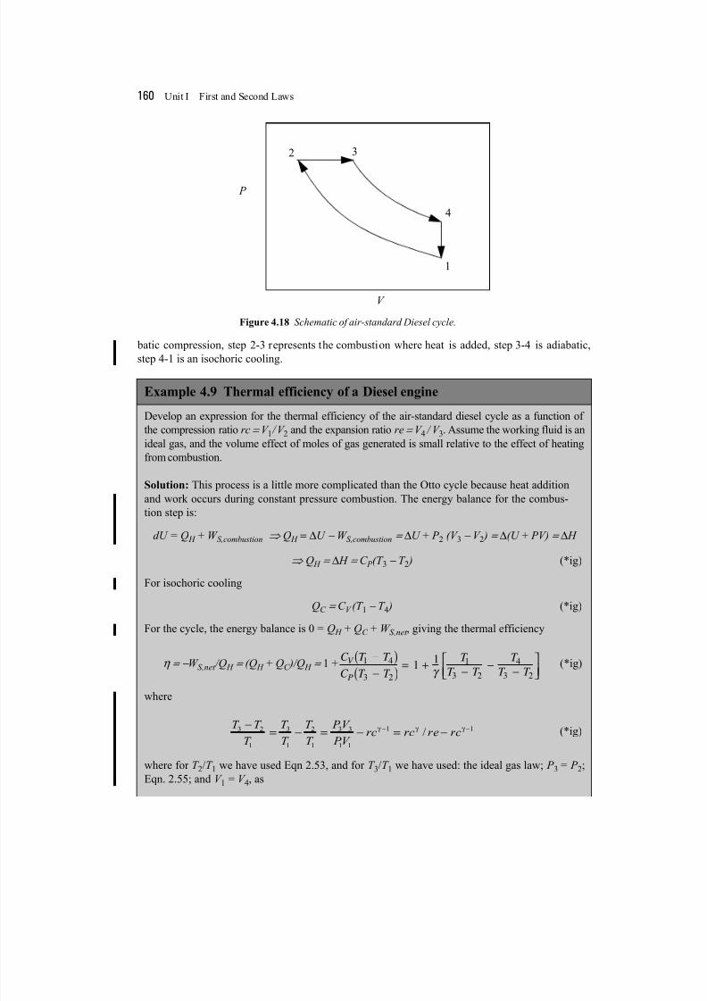
tion at constant pressure. In the air-standard Diesel cycle shown in Figure 4.18, step 1-2 is an adia-
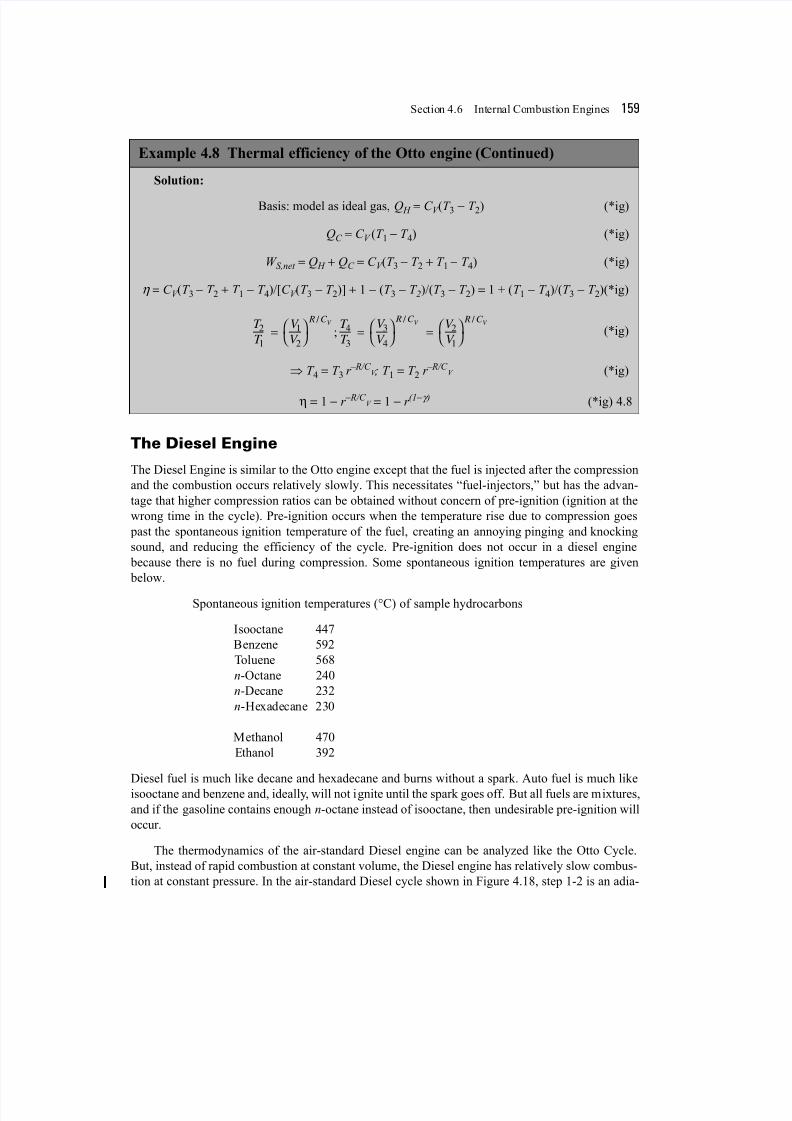
Solution:
Basis: model as ideal gas, Q H = C V (T 3 − T 2) (*ig)
QC = C V (T 1 − T 4) (*ig)
W S,net = Q H + QC = C V (T 3 − T 2 + T 1 − T 4) (*ig)
η = C V (T 3 − T 2 + T 1 − T 4)/[C V (T 3 − T 2)] + 1 − (T 3 − T 2)/(T 3 − T 2) = 1 + (T 1 − T 4)/(T 3 − T 2)(*ig)
(*ig)
⇒ T 4 = T 3 r –R/C V ; T 1 = T 2 r –R/C
V (*ig)
η = 1 − r − R/C V = 1 − r (1−γ ) (*ig) 4.8
Example 4.8 Thermal efficiency of the Otto engine (Continued)
T
T
V
V
T
T
V
V
V
V
R C R C R C V V V
2
1
1
2
4
3
3
4
2
1
=
=
=
/ / /
;
8/12/2019 Pg 160 Expanded
http://slidepdf.com/reader/full/pg-160-expanded 2/3
160 Unit I First and Second Laws
batic compression, step 2-3 represents the combustion where heat is added, step 3-4 is adiabatic,step 4-1 is an isochoric cooling.
Example 4.9 Thermal efficiency of a Diesel engine
Develop an expression for the thermal efficiency of the air-standard diesel cycle as a function of
the compression ratio rc = V 1 /V 2 and the expansion ratio re = V 4 / V 3. Assume the working fluid is an
ideal gas, and the volume effect of moles of gas generated is small relative to the effect of heating
from combustion.
Solution: This process is a little more complicated than the Otto cycle because heat addition
and work occurs during constant pressure combustion. The energy balance for the combus-
tion step is:
dU = Q H + W S,combustion ⇒ Q H = ∆U − W S,combustion = ∆U + P 2 (V 3 − V 2 ) = ∆(U + PV) = ∆ H
⇒ Q H = ∆ H = C P (T 3 − T 2 ) (*ig)
For isochoric cooling
QC = C V (T 1 − T 4 ) (*ig)
For the cycle, the energy balance is 0 = Q H + QC + W S,net , giving the thermal efficiency
η = − W S,net /Q H = (Q H + QC )/Q H = 1 + (*ig)
where
(*ig)
where for T 2/T 1 we have used Eqn 2.53, and for T 3/T 1 we have used: the ideal gas law; P 3 = P 2;
Eqn. 2.55; and V 1 = V 4, as
P
V
1
2 3
4
Figure 4.18 Schematic of air-standard Diesel cycle.
C T T
C T T
T
T T
T
T T
V
P
1 4
3 2
1
3 2
4
3 2
1 1−( )
−( ) = + − − −
γ
T T
T
T
T
T
T
P V
PV rc rc re rc
3 2
1
3
1
2
1
3 3
1 1
1 1-
= - = - = -- -g g g
/
8/12/2019 Pg 160 Expanded
http://slidepdf.com/reader/full/pg-160-expanded 3/3
Section 4.7 Fluid Flow 161
4.7 FLUID FLOW
Consider the general flow system of Fig. 4.19a in which work and heat are transferred and the fluid
undergoes changes in kinetic and potential energy. Recognize that the compressor or pump in the
schematic could be replaced with an expander or turbine. Rather than deriving an integral equation between points 1 and 4 in the schematic, let us consider a balance over a differential element at
steady-state as shown in Fig. 4.19b where the possibility of heat and work transfer are permitted.
The steady-state balance for a single stream becomes:1
For a differential element, H out = H in + dH , and
,
The differential balance becomes
(*ig)
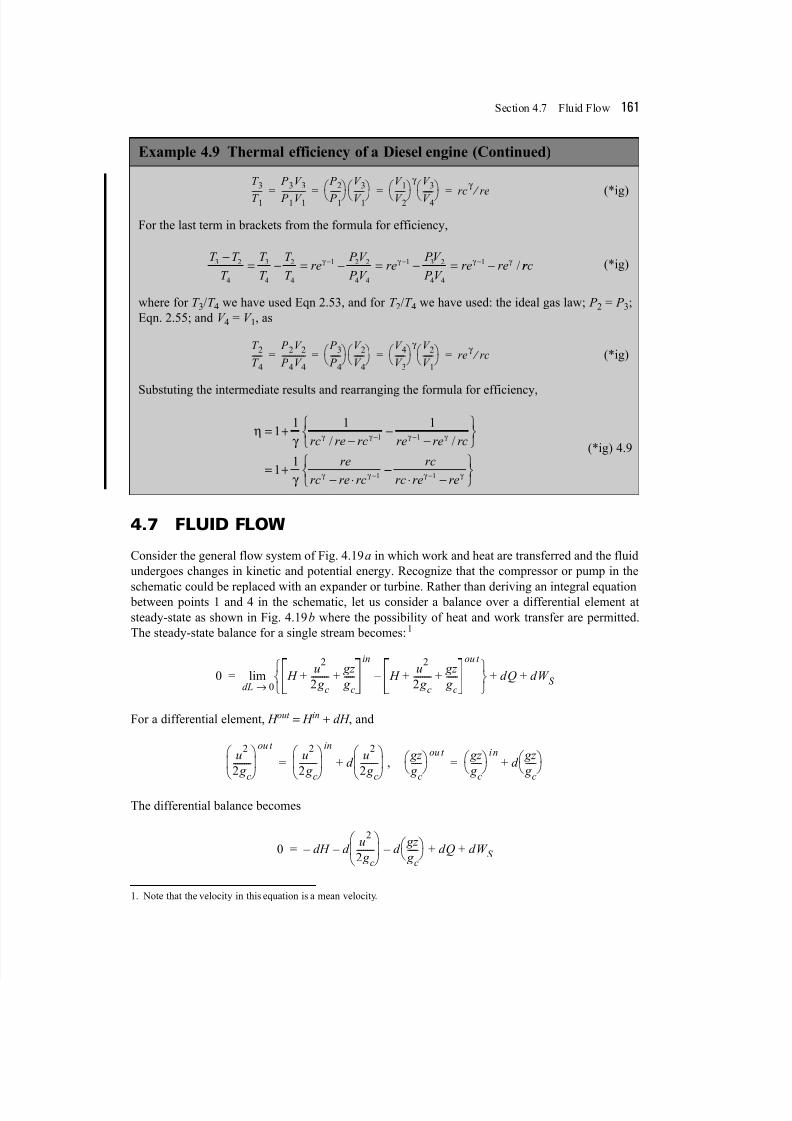
For the last term in brackets from the formula for efficiency,
(*ig)
where for T 3/T 4 we have used Eqn 2.53, and for T 2/T 4 we have used: the ideal gas law; P 2 = P 3;
Eqn. 2.55; and V 4 = V 1, as
(*ig)
Substuting the intermediate results and rearranging the formula for efficiency,
(*ig) 4.9
1. Note that the velocity in this equation is a mean velocity.
Example 4.9 Thermal efficiency of a Diesel engine (Continued)
T 3
T 1-----
P 3V 3
P 1V 1------------
P 2
P 1------
V 3
V 1------
V 1
V 2------
γ V 3
V 4------
rc
γ
re ⁄ = = = =
T T
T
T
T
T
T re
P V
P V re
PV
P V re re
3 2
4
3
4
2
4
1 2 2
4 4
1 3 2
4 4
1-
= - = - = - = -- - -g g g g / r rc
T 2
T 4-----
P 2V 2
P 4V 4------------
P 3
P 4------
V 2
V 4------
V 4
V 3------
γ V 2
V 1------
re
γ rc ⁄ = = = =
hg
g
g g g g
g g
= +-
--
ÏÌÓ
¸˝˛
= +- ◊
- -
-
1 1 1 1
1 1
1 1
1
rc re rc re re rc
re
rc re rc
/ /
--◊ -
ÏÌÓ
¸˝˛
-
rc
rc re reg g 1
0 H u
2
2 g c--------
gz
g c-----+ +
in
H u
2
2 g c--------
gz
g c-----+ +
ou t
–
dL 0→lim dQ dW S + +=
u2
2 g c
--------
ou t u
2
2 g c
--------
in
d u
2
2 g c
--------
+= gz
g c
----- ou t gz
g c
----- in
d gz
g c
----- +=
0 dH – d u
2
2 g c--------
– d gz
g c-----
– dQ dW S + +=