pg 720 pii - siemens · pg 720 pii programming device c79000-g7076-c756-02 chapters 1 to 4 of the...
TRANSCRIPT

Preface, Contents
Product Overview 1
Unpacking and Setting Up the PG 720 2
Getting to Know the PG 720 3
Installing and Operating thePG 720 4
PG 720 Expansions 5
Configuring the PG 720 6
Error Diagnostics 7
Hardware Information 8
Appendices
ESD GuidelinesA
Glossary, Index
11/99
C79000-G7076-C756
Edition 02
PG 720 PIIProgramming Device
Manual
SIMATIC
ii
�"#-�'�(/�&��)(.�#(-�().#��-�1"#�"�3)/�-")/&��)�-�,0��.)��(-/,��3)/,�)1(�*�,-)(�&�-� �.3���-�1�&&��-�.)
*,).��.�."��*,)�/�.��(���)((��.����+/#*'�(.���"�-��().#��-��,��"#!"&#!".���#(�."��'�(/�&��3���1�,(#(!
.,#�(!&���(���,��'�,%����-� )&&)1-����),�#(!�.)�."��&�0�&�) ���(!�,
!Danger
#(�#��.�-�."�.����."��-�0�,��*�,-)(�&�#($/,3��),�-/�-.�(.#�&�*,)*�,.3���'�!�������,�-/&.�# �*,)*�,�*,���/.#)(-��,�().�.�%�(�
!Warning
#(�#��.�-�."�.����."��-�0�,��*�,-)(�&�#($/,3��),�-/�-.�(.#�&�*,)*�,.3���'�!������,�-/&.�# �*,)*�,�*,���/.#)(-�,��().�.�%�(�
!Caution
#(�#��.�-�."�.�'#(),�*�,-)(�&�#($/,3�),�*,)*�,.3���'�!����(�,�-/&.�# �*,)*�,�*,���/.#)(-��,��().�.�%�(�
Note
�,�1-�3)/,��..�(.#)(�.)�*�,.#�/&�,&3�#'*),.�(.�#( ),'�.#)(�)(�."��*,)�/�.��"�(�&#(!�."��*,)�/�.��),�.)���*�,.#�/&�,
*�,.�) �."���)�/'�(.�.#)(�
�(&3������������� �����-")/&������&&)1���.)�#(-.�&&��(��1),%�)(�."#-��+/#*'�(.���/�&# #���*�,-)(-�#(�."�
-�(-��) �."��-� �.3�!/#��&#(�-�) �."#-���(/�&��,���� #(����-�*�,-)(-�1")��,���/."),#4���.)��)''#--#)(��.)!,)/(���(��.)�.�!��+/#*'�(.��-3-.�'-��(���#,�/#.-�#(����),��(���1#."��-.��&#-"���-� �.3�*,��.#��-��(�
-.�(��,�-�
�).��."�� )&&)1#(!
!Warning
�"#-���0#����(��#.-��)'*)(�(.-�'�3�)(&3����/-��� ),�."���**&#��.#)(-���-�,#����#(�."����.�&)!�),�."��.��"(#��&��-�,#*.#)(���(��)(&3�#(��)((��.#)(�1#."���0#��-�),��)'*)(�(.-� ,)'�)."�,�'�(/ ��./,�,-�1"#�"�"�0�����(�**,)0���),�,��)''�(�����3��#�'�(-�
�"#-�*,)�/�.���(�)(&3� /(�.#)(��),,��.&3��(��-� �&3�# �#.�#-�.,�(-*),.����-.),����-�.�/*���(��#(-.�&&����),,��.&3���(�)*�,�.����(��'�#(.�#(����-�,��)''�(����
������ ��������� �������(�������� �������,��,�!#-.�,���.,���'�,%-�) ��#�'�(-����
�"#,��*�,.#�-�/-#(!� ),�."�#,�)1(�*/,*)-�-��(3�)."�,�(�'�-�#(�."#-��)�/'�(.�1"#�"�,� �,�.)�.,���'�,%-�'#!".
#( ,#(!��/*)(�."��,#!".-�) �."��.,���'�,%�)1(�,-�
���"�0���"��%���."���)(.�(.-�) �."#-�'�(/�&� ),��!,��'�(.�1#."�."�"�,�1�,���(��-) .1�,����-�,#������#(�����0#�.#)(-���(().����*,��&/����(.#,�&3��1����(().�!/�,�(.��� /&&��!,��'�(.���)1�0�,��."����.��#(�."#-'�(/�&��,��,�0#�1���,�!/&�,&3��(���(3�(���--�,3��),,��.#)(-�#(�&/����#(-/�-�+/�(.���#.#)(-���/!!�-.#)(-� ),�#'*,)0�'�(.��,��1�&�)'���
� Siemens AG 1999���"(#��&���.��-/�$��.�.)��"�(!��
Disclaimer of LiabilityCopyright � Siemens AG 1999 All rights reserved
�"��,�*,)�/�.#)(��.,�(-'#--#)(��),�/-��) �."#-��)�/'�(.�),�#.-��)(.�(.-�#-().�*�,'#..���1#.")/.��2*,�--�1,#..�(��/."),#.3��� �(��,-�1#&&����&#��&�� ),��'�!�-���&&�,#!".-��#(�&/�#(!�,#!".-��,��.����3�*�.�(.�!,�(.�),�,�!#-.,�.#)() ���/.#&#.3�')��&�),���-#!(���,��,�-�,0���
�#�'�(-�����,�#�"��/.)'�.#-#�,/(!-6�/(���(.,#��-.��"(#%��-�"�� .-!��#�.��(�/-.,#�6�/.)'�.#-#�,/(!--3-.�'��)-. ��"������5�6������/�,(��,!
Siemens Aktiengesellschaft C79000-G7076-C756
Safety Guidelines
Qualified Personnel
Correct Usage
Trademarks

iiiPG 720 PII Programming DeviceC79000-G7076-C756-02
Preface
This manual contains all the information you need for working with thePG 720PII programming device. You can use this information to do thefollowing:
� Unpack the programming device and power it up.
� Familiarize yourself with the functions and settings of the variouscomponents (display, keyboard, programming facilities, etc.).
� Connect the programming device to other units of equipment(programmable logic controllers, other programming devices).
� Expand your system, provided you comply with the necessaryconditions.
� Analyze and eliminate simple problems.
The following persons require the manual:
� Users commissioning the programming device themselves orworking with it (editing, debugging).
� System administrators operating the programming device in anetwork.
� Service and maintenance personnel using the PG 720PII for systemexpansion purposes or error/fault analysis.
This manual describes the version of the PG 720PII as available inApril 1999. The Product Information Bulletin supplied with thePG 720PII contains the latest technical specifications for yourprogramming device.
The approvals, certificates, and licenses for your device are suppliedalong with the Product Information Bulletin.
Within this publication the product name PG 720PII is givenabbreviated to PG 720 or PG.
Along with your PG 720, you also receive the following documentswhich you require for commissioning the device:
� The Product Information Bulletin with the valid technicalspecifications and the PG 720 installed Software .
For more detailed information about handling the software, please referto the appropriate manuals (for example, the STEP 5 manual).
Purpose of theManual
Audience
Where is thisManual Valid?
Licenses
Product namePG 720PII
Where to FindInformation

ivPG 720 PII Programming Device
C79000-G7076-C756-02
Chapters 1 to 4 of the manual contain the most important instructionsfor commissioning and using the PG 720. Chapters 5 to 8 arereference sections required in special situations.
Setting up and getting to know your deviceBefore you start to use your programming device, you should readabout setting up the device in Chapter 2 and about the componentsand functions of the PG 720 in Chapter 3.
InstallationChapter 4 describes the basic steps necessary for commissioning thePG 720. This chapter also contains instructions for working withsubmodules and memory cards for programmable logic controllers andadditional interfaces.
ExpansionChapter 5 describes how to expand your PG 720 (for example,installation of memory expansions). Please observe the safetyinstructions in this section.
ConfigurationModifications made to the system hardware may make it necessary foryou to adapt the original hardware configuration. This is described inChapter 6.
Error/fault diagnosticsChapter 7 explains how to deal with simple faults and problems thatyou can diagnose and, in some cases, eliminate yourself.
Reference dataChapter 8 contains information about hardware addresses, interruptassignments, and connecting cables.
ESD guidelinesThe guidelines on the handling of electrostatically sensitive devices areparticularly important for service and maintenance technicians who areinstalling expansion units or carrying out error analysis with thePG 720.
GlossaryThe glossary defines and explains important terms.
Alphabetical indexThe alphabetical index will help you to find passages in the text relatingto important terms and keywords quickly and reliably.
If you have any questions concerning subjects not covered in themanual, simply get in touch with the Siemens representative in yourarea or call the SIMATIC Hotline. The addresses are listed in yourProduct Information Bulletin.
If you have any questions about the manual itself or would like to makeor suggestions, please complete the reply card at the end of themanual. We would also appreciate it if you would include your ownopinion and appraisal of the manual on the reply card.
Structure of theManual
AdditionalAssistance
Preface

vPG 720 PII Programming DeviceC79000-G7076-C756-02
Contents
Preface iii. . . . . . . . . . . . . . . . . . . . . . . . . . . . . . . . . . . . . . . . . . . . . . . . . . . . . . . . . . . . . . . .
1 Product Overview 1-1. . . . . . . . . . . . . . . . . . . . . . . . . . . . . . . . . . . . . . . . . . . . . . . . . . . . . .
2 Unpacking and Setting Up the PG 720 2-1. . . . . . . . . . . . . . . . . . . . . . . . . . . . . . . . . . .
2.1 Setting Up the PG 720 2-2. . . . . . . . . . . . . . . . . . . . . . . . . . . . . . . . . . . . . . . . . . .
2.2 Moving the Programming Device 2-6. . . . . . . . . . . . . . . . . . . . . . . . . . . . . . . . . .
3 Getting to Know the PG 720 3-1. . . . . . . . . . . . . . . . . . . . . . . . . . . . . . . . . . . . . . . . . . . . .
3.1 Hardware Components of the PG 720 3-2. . . . . . . . . . . . . . . . . . . . . . . . . . . . . .
3.2 Display 3-8. . . . . . . . . . . . . . . . . . . . . . . . . . . . . . . . . . . . . . . . . . . . . . . . . . . . . . . .
3.3 Keyboard 3-9. . . . . . . . . . . . . . . . . . . . . . . . . . . . . . . . . . . . . . . . . . . . . . . . . . . . . .
3.4 Trackball 3-14. . . . . . . . . . . . . . . . . . . . . . . . . . . . . . . . . . . . . . . . . . . . . . . . . . . . . . .
3.5 Drives 3-16. . . . . . . . . . . . . . . . . . . . . . . . . . . . . . . . . . . . . . . . . . . . . . . . . . . . . . . . .
3.6 CD-ROM Drive 3-18. . . . . . . . . . . . . . . . . . . . . . . . . . . . . . . . . . . . . . . . . . . . . . . . . .
3.7 External Power Unit and Battery 3-19. . . . . . . . . . . . . . . . . . . . . . . . . . . . . . . . . . .
3.8 Sound 3-20. . . . . . . . . . . . . . . . . . . . . . . . . . . . . . . . . . . . . . . . . . . . . . . . . . . . . . . . .
4 Installing and Operating the PG 720 4-1. . . . . . . . . . . . . . . . . . . . . . . . . . . . . . . . . . . . .
4.1 Connecting the PG 720 to the Power Supply 4-2. . . . . . . . . . . . . . . . . . . . . . . .
4.2 Battery Mode 4-3. . . . . . . . . . . . . . . . . . . . . . . . . . . . . . . . . . . . . . . . . . . . . . . . . . .
4.3 Connecting I/O Devices 4-7. . . . . . . . . . . . . . . . . . . . . . . . . . . . . . . . . . . . . . . . . .
4.4 Working with SIMATIC S5 Memory Submodules 4-12. . . . . . . . . . . . . . . . . . . . .
4.5 Working with SIMATIC Memory Cards 4-14. . . . . . . . . . . . . . . . . . . . . . . . . . . . .
4.6 Working with PC Cards 4-15. . . . . . . . . . . . . . . . . . . . . . . . . . . . . . . . . . . . . . . . . .
4.7 Connecting the PG 720 to other SIMATIC S5 Units 4-17. . . . . . . . . . . . . . . . . .
4.8 Connecting the PG 720 to a SIMATIC S7 Network (MPI/DP) 4-21. . . . . . . . . .
4.9 Networking the PG 720 with Other Stations on PROFIBUS 4-23. . . . . . . . . . .
4.10 Networking the PG 720 and Other Computers on Industrial Ethernet 4-24. . .
4.11 Connection under Windows 4-24. . . . . . . . . . . . . . . . . . . . . . . . . . . . . . . . . . . . . . .
viPG 720 PII Programming Device
C79000-G7076-C756-02
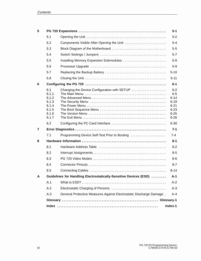
5 PG 720 Expansions 5-1. . . . . . . . . . . . . . . . . . . . . . . . . . . . . . . . . . . . . . . . . . . . . . . . . . . . .
5.1 Opening the Unit 5-2. . . . . . . . . . . . . . . . . . . . . . . . . . . . . . . . . . . . . . . . . . . . . . . .
5.2 Components Visible After Opening the Unit 5-4. . . . . . . . . . . . . . . . . . . . . . . . .
5.3 Block Diagram of the Motherboard 5-5. . . . . . . . . . . . . . . . . . . . . . . . . . . . . . . . .
5.4 Switch Settings / Jumpers 5-7. . . . . . . . . . . . . . . . . . . . . . . . . . . . . . . . . . . . . . . .
5.5 Installing Memory Expansion Submodules 5-8. . . . . . . . . . . . . . . . . . . . . . . . . .
5.6 Processor Upgrade 5-9. . . . . . . . . . . . . . . . . . . . . . . . . . . . . . . . . . . . . . . . . . . . . .
5.7 Replacing the Backup Battery 5-10. . . . . . . . . . . . . . . . . . . . . . . . . . . . . . . . . . . . .
5.8 Closing the Unit 5-11. . . . . . . . . . . . . . . . . . . . . . . . . . . . . . . . . . . . . . . . . . . . . . . . .
6 Configuring the PG 720 6-1. . . . . . . . . . . . . . . . . . . . . . . . . . . . . . . . . . . . . . . . . . . . . . . . .
6.1 Changing the Device Configuration with SETUP 6-2. . . . . . . . . . . . . . . . . . . . . 6.1.1 The Main Menu 6-5. . . . . . . . . . . . . . . . . . . . . . . . . . . . . . . . . . . . . . . . . . . . . . . . . 6.1.2 The Advanced Menu 6-14. . . . . . . . . . . . . . . . . . . . . . . . . . . . . . . . . . . . . . . . . . . . . 6.1.3 The Security Menu 6-19. . . . . . . . . . . . . . . . . . . . . . . . . . . . . . . . . . . . . . . . . . . . . . 6.1.4 The Power Menu 6-21. . . . . . . . . . . . . . . . . . . . . . . . . . . . . . . . . . . . . . . . . . . . . . . . 6.1.5 The Boot Sequence Menu 6-23. . . . . . . . . . . . . . . . . . . . . . . . . . . . . . . . . . . . . . . . 6.1.6 The Version Menu 6-25. . . . . . . . . . . . . . . . . . . . . . . . . . . . . . . . . . . . . . . . . . . . . . . 6.1.7 The Exit Menu 6-26. . . . . . . . . . . . . . . . . . . . . . . . . . . . . . . . . . . . . . . . . . . . . . . . . .
6.2 Configuring the PC Card Interface 6-30. . . . . . . . . . . . . . . . . . . . . . . . . . . . . . . . .
7 Error Diagnostics 7-1. . . . . . . . . . . . . . . . . . . . . . . . . . . . . . . . . . . . . . . . . . . . . . . . . . . . . . .
7.1 Programming Device Self-Test Prior to Booting 7-4 . . . . . . . . . . . . . . . . . . . . .
8 Hardware Information 8-1. . . . . . . . . . . . . . . . . . . . . . . . . . . . . . . . . . . . . . . . . . . . . . . . . . .
8.1 Hardware Address Table 8-2. . . . . . . . . . . . . . . . . . . . . . . . . . . . . . . . . . . . . . . . .
8.2 Interrupt Assignments 8-5. . . . . . . . . . . . . . . . . . . . . . . . . . . . . . . . . . . . . . . . . . . .
8.3 PG 720 Video Modes 8-6. . . . . . . . . . . . . . . . . . . . . . . . . . . . . . . . . . . . . . . . . . . .
8.4 Connector Pinouts 8-7. . . . . . . . . . . . . . . . . . . . . . . . . . . . . . . . . . . . . . . . . . . . . . .
8.5 Connecting Cables 8-14. . . . . . . . . . . . . . . . . . . . . . . . . . . . . . . . . . . . . . . . . . . . . .
A Guidelines for Handling Electrostatically-Sensitive Devices (ESD) A-1. . . . . . . . .
A.1 What is ESD? A-2. . . . . . . . . . . . . . . . . . . . . . . . . . . . . . . . . . . . . . . . . . . . . . . . . . .
A.2 Electrostatic Charging of Persons A-3. . . . . . . . . . . . . . . . . . . . . . . . . . . . . . . . .
A.3 General Protective Measures Against Electrostatic Discharge Damage A-4.
Glossary Glossary- 1. . . . . . . . . . . . . . . . . . . . . . . . . . . . . . . . . . . . . . . . . . . . . . . . . . . . . . . . . .
Index Index- 1. . . . . . . . . . . . . . . . . . . . . . . . . . . . . . . . . . . . . . . . . . . . . . . . . . . . . . . . . . . . .
Contents

1-1PG 720 PII Programming DeviceC79000-G7076-C756-02
Product Overview
The PG 720 programming device is a self-contained unit designedspecifically for an automation environment. Its performance, ergonomicdesign, and equipment make it a unit particularly suitable for maintenanceand service as well as for programming, configuring, debugging, andinstalling SIMATIC programmable logic control systems.
SIEMENS
You can use the PG 720 programming device to program SIMATIC S5 andSIMATIC S7 programmable logic controllers. It is equipped with thefollowing:
� Interface ports for connection to programmable logic controllers.
� Programming facilities for S5 memory submodules and S5/S7memory cards.
The PG 720 is supplied with system and automation software. Thesoftware components are listed in the Product Information leaflet.
Application
The PG’s Hardwareand Software
1
1-2PG 720 PII Programming Device
C79000-G7076-C756-02
Compared with a PC with standard hardware and software, thePG 720 programming device of the SIMATIC family has numerousadvantages:
� You can develop, debug, and document user programs forSIMATIC S5 and SIMATIC S7 programmable logic controllers withthe PG 720 without the need for additional hardware or software.
� The rugged design and practical functions of the PG 720 make itparticularly suitable for use on-site under tough industrial conditions.It is extremely light and easy to transport. The PG 720 meets thespecific requirements of industrial environments such as noiseimmunity, compliance with the relevant standards, ruggedness,simple transportation, and commissioning.
� The PG 720 is equipped with a battery allowing it to be operatedwithout a mains connection.
� The PG 720 can be set up and operated in a large number ofdifferent ways and positions, and can therefore be used practicallyanywhere it is needed.
� The PG 720 has all the integral ports necessary for connecting it toSIMATIC automation devices:
– Programming interface for SIMATIC S5 memory submodules.
– Programming interface for SIMATIC S5 and SIMATIC S7memory cards in credit card format.
– Communication interfaces for connection to S5 and S7programmable logic controllers.
� The PG 720 is supplied with all the necessary system andautomation software already installed on the hard disk.
� Since Windows 98 is also already installed, you can, of course, alsouse the PG 720 as a stand-alone workstation, and run all thestandard software available on the market that requires MS-DOS orWindows.
� In terms of performance and expansion capability, yourprogramming device meets all the normal requirements of a PC.This means that the PG 720 can also be used as a fully-fledgedpersonal computer.
Advantages of thePG 720
Product Overview

2-1PG 720 PII Programming DeviceC79000-G7076-C756-02
Unpacking and Setting Up the PG 720
This chapter contains important information about unpacking, settingup, and transporting the PG 720, such as:
� Opening and closing the keyboard
� Changing the angle of inclination of the device
� Using the extra pull-out support
� How to move the unit.
Section Contents Page
2.1 Setting Up the PG 720 2-2
2.2 Moving the Programming Device 2-6
What Does ThisChapter Contain?
ChapterOverview
2
2-2PG 720 PII Programming Device
C79000-G7076-C756-02
2.1 Setting Up the PG 720
Unpack your PG 720 as follows:
1. Remove the packing.
2. Do not throw the original packing away. Keep it in case you have toship or transport the unit again at some time in the future.
3. Check the packing list to make sure that no components aremissing.
!Caution
Risk of damage!
Moisture inside the unit can cause serious damage.
When transporting the unit in cold weather, when it may be submittedto extreme variations in temperature, make sure that the unit isallowed to reach room temperature slowly before you switch it on.
If condensation has formed, this must be allowed to evaporate beforeyou switch on. If, for example, the unit is subjected to a temperaturechange from –20° C to +20° (–4° F to +68° F) you should waitapproximately 12 hours before switching on the unit.
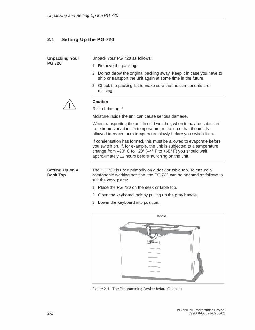
The PG 720 is used primarily on a desk or table top. To ensure acomfortable working position, the PG 720 can be adapted as follows tosuit the work place:
1. Place the PG 720 on the desk or table top.
2. Open the keyboard lock by pulling up the gray handle.
3. Lower the keyboard into position.
Handle
Figure 2-1 The Programming Device before Opening
Unpacking YourPG 720
Setting Up on aDesk Top
Unpacking and Setting Up the PG 720

2-3PG 720 PII Programming DeviceC79000-G7076-C756-02
With the keyboard open, you can incline the PG 720 to any anglebetween 0° and 90°. To adjust the angle, proceed as follows:
1. Lower the keyboard into position.
2. Pull the support (Figure 2-4) out of the rear of the stand and, ifnecessary, pull out the extra support hoop.
3. Incline the unit to an angle that will allow you to work comfortably.
Stand
Keyboard opened
Pivot
Figure 2-2 Changing the Angle of Inclination
Note
When you change the angle of inclination, make sure that thekeyboard cable is not trapped between the device and the stand.
!Caution
Risk of injury!
There is a danger of the unit tipping over if it is set up at an angle ofinclination of more than 15° without using the pull-out support. Thiscould lead to personal injury and also damage to the unit.
If the angle of inclination is greater than 15°, you must use the pull-outsupport and, if necessary, the extra support hoop in the stand.
Changing theAngle ofInclination
Unpacking and Setting Up the PG 720
2-4PG 720 PII Programming Device
C79000-G7076-C756-02
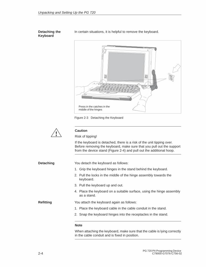
In certain situations, it is helpful to remove the keyboard.
Press in the catches in themiddle of the hinges
Figure 2-3 Detaching the Keyboard
!Caution
Risk of tipping!
If the keyboard is detached, there is a risk of the unit tipping over.Before removing the keyboard, make sure that you pull out the supportfrom the device stand (Figure 2-4) and pull out the additional hoop.
You detach the keyboard as follows:
1. Grip the keyboard hinges in the stand behind the keyboard.
2. Pull the locks in the middle of the hinge assembly towards thekeyboard.
3. Pull the keyboard up and out.
4. Place the keyboard on a suitable surface, using the hinge assemblyas a stand.
You attach the keyboard again as follows:
1. Place the keyboard cable in the cable conduit in the stand.
2. Snap the keyboard hinges into the receptacles in the stand.
Note
When attaching the keyboard, make sure that the cable is lying correctlyin the cable conduit and is fixed in position.
Detaching theKeyboard
Detaching
Refitting
Unpacking and Setting Up the PG 720

2-5PG 720 PII Programming DeviceC79000-G7076-C756-02
When the keyboard is attached to the unit, its angle of inclination is 6°,the height of the middle row of keys is 30 mm (about 1 inch). When it isdetached, the angle of inclination is 4.5°, and the height of the middlerow of keys is 27 mm. This is an ideal ergonomic design to allow acomfortable working position.
If no table or desk is available, the unit can be operated on the floor.You can adjust the casing and display through approximately 90o intothe horizontal plane.
CD-ROM drive
Stand
Pivot
Support Extra support hoop
Figure 2-4 Horizontal Operating Position Without Keyboard
Keyboard Angle
HorizontalPositionAdjustment
Unpacking and Setting Up the PG 720

2-6PG 720 PII Programming Device
C79000-G7076-C756-02
2.2 Moving the Programming Device
The PG 720 is easy to carry. Before carrying it, however, you shouldtake the following measures:
1. Shut down the operating system. To prevent data loss, you mustexit Windows 98 completely. Windows 98 issues a message toinform you when it is safe to switch off the device.
2. Unplug all the connecting cables.
3. Close the covers protecting the ports and connections on theright-hand and left-hand side panels.
4. Bring the unit into an upright position.
5. Raise the keyboard and lock it by pressing it against the front panelof the unit. The latches on the right and left snap in. Make sure thatboth catches are properly locked .
6. If you only want to carry the unit for a short distance, use thehandle.
7. If you want to move the PG 720 over larger distances, pack the unitand all its accessories in the carrying bag supplied.
Figure 2-5 PG 720 Ready for Transport
Despite the rugged design of the PG 720, its internal components aresensitive to severe vibration or jolts. When moving the PG 720, youmust therefore make sure that it is protected from severe mechanicalforces.
Use the original packing material if you have to ship the PG 720 fromone location to another.
Preparations
Carrying thePG 720
Unpacking and Setting Up the PG 720

3-1PG 720 PII Programming DeviceC79000-G7076-C756-02
Getting to Know the PG 720
This chapter contains all the information you require about the mostimportant components of the device, such as:
� LED displays
� Drives
� Keyboard
� Programming facilities of the PG 720
� External power unit and battery.
Section Contents Page
3.1 Hardware Components of the PG 720 3-2
3.2 Display 3-8
3.3 Keyboard 3-9
3.4 Trackball 3-14
3.5 Drives 3-16
3.6 CD-ROM Drive 3-18
3.7 External Power Unit and Battery 3-19
3.8 Sound 3-20
What Does ThisChapter Contain?
ChapterOverview
3

3-2PG 720 PII Programming Device
C79000-G7076-C756-02
3.1 Hardware Components of the PG 720
You can access all of the important operator controls and displays fromthe front, base, or sides of the unit. Figure 3-1 shows the front of thePG 720.
AkkuPowerAccessing external storage mediumSubmodule programming activeMPI/DP port active
6 Keyboard
7 Cover flap for COM1/COM2 port, MPI/DP port, mouse port, and LPT1/printerport 1)
8 Trackball
9 Catches for locking keyboard
10 Pivot
11 Protector strip
12 CD-ROM drive 2)
14 Speaker
2
5
1
4
8
10
11
913Detail
LEDs
See Table 3-1 for more information onthe Akku and Power LEDs.
13Detail
1 On/Off switch
2 Carrying handle
3 LC display
4 Cover flap for module ports, memory cardports, PCMCIA ports, and floppy disk drive 1)
5 Stand
12
1) The cover flaps are used to protect the ports from dust,and can be removed and replaced as required.
2) Can be accessed from the base when the device is turnedupside down.
3) Press this button for 1 second in order to switch on the programming device. A hard reset (override) is performed if you hold down the button longer than 7 seconds.
4) External storage media: hard disk drive, floppy disk drive, CD-ROM drive.
6
7
14
93
14
Figure 3-1 The Front of the PG 720
Front
Getting to Know the PG 720

3-3PG 720 PII Programming DeviceC79000-G7076-C756-02
Table 3-1 The LEDs and What They Mean
Label LED Meaning
grn Device is in mains supply mode; external powerunit is supplying power
or Device is in mains supply mode; battery is re-charging
Akku rd Device is in battery mode; battery charge levellow
blk Device is in battery mode; battery has shut downor no battery installed
Power grn
grnflashing
Device is on, battery mode is selected and bat-tery is not down
Device status is “save to DRAM”
blk Device is off or battery has shut down in batterymode (battery down)
grn Accessing external storage medium (hard disk,CD-ROM, floppy disk)
grn Submodule programming is in progress
MPI/DP grn MPI port is active
Table 3-2 The Mode LEDs
Power Akku
blk grn a.c. mains supply, battery charged or not installed
blk or a.c. mains supply, battery is recharging
blk blk Device is off or battery is down in battery mode
grn blk Device is on, battery mode
grn grn Device is on, a.c. mains supply
grn or Device is on, a.c. mains supply and battery is recharging
grn rd Device is on, battery charge level is low and battery modeis selected
grn = greenrd = redor = orangeblk = black, dark
Note
Recharging stops when the battery is fully charged or if, for example,the temperature overshoots the maximum permissible limit forrecharging. You can check the battery charge level in Windows 98.
The LEDs andWhat They Mean
The Mode LEDsof the PG 720
Getting to Know the PG 720
3-4PG 720 PII Programming Device
C79000-G7076-C756-02
Note
Press the On/Off button for approximately one second to switch on thedevice. The device switches off automatically if it is powered down inWindows. If it is not in Windows, switch off the device by pressing theOn/Off button.
If you work under Windows 98, always use the Shut Down menu in theStart pop-up to switch off the programming device. The PG 720switches off automatically when you exit Windows.
Holding down the On/Off button for longer than seven seconds triggersthe override function. The device resets and automatically reboots(useful, for example, if the system freezes).
Getting to Know the PG 720
3-5PG 720 PII Programming DeviceC79000-G7076-C756-02
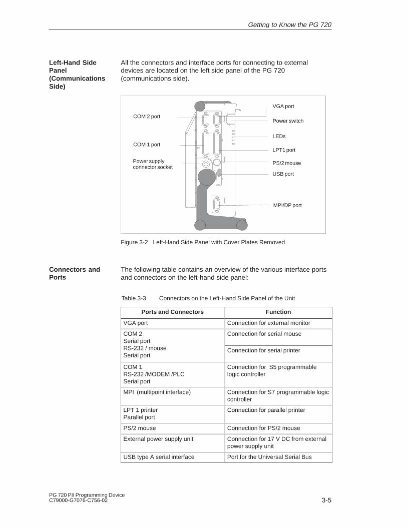
All the connectors and interface ports for connecting to externaldevices are located on the left side panel of the PG 720(communications side).
LPT1 port
USB port
VGA port
Power switch
LEDs
PS/2 mouse
COM 2 port
COM 1 port
Power supplyconnector socket
MPI/DP port
Figure 3-2 Left-Hand Side Panel with Cover Plates Removed
The following table contains an overview of the various interface portsand connectors on the left-hand side panel:
Table 3-3 Connectors on the Left-Hand Side Panel of the Unit
Ports and Connectors Function
VGA port Connection for external monitor
COM 2Serial port
Connection for serial mouse
RS-232 / mouseSerial port
Connection for serial printer
COM 1RS-232 /MODEM /PLCSerial port
Connection for S5 programmablelogic controller
MPI (multipoint interface) Connection for S7 programmable logiccontroller
LPT 1 printer Connection for parallel printerLPT 1 rinterParallel port
Connection for arallel rinter
PS/2 mouse Connection for PS/2 mouse
External power supply unit Connection for 17 V DC from externalpower supply unit
USB type A serial interface Port for the Universal Serial Bus
Left-Hand SidePanel(CommunicationsSide)
Connectors andPorts
Getting to Know the PG 720

3-6PG 720 PII Programming Device
C79000-G7076-C756-02
You access the slots for programming S5 submodules, S5/S7 memorycards, the PCMCIA port, and the disk drive from the right-hand side ofthe PG 720 (processing side).
S5 submodule port
Ejector for PCMCIAcards
PC cards types I/II/III; slot 1
Ejector for PCcards
Orientation point
PC cards types I/II; slot 2
3.5 in. disk drive
Ejector for diskettes
Access LED
Memory card port
CD-ROM drive
Figure 3-3 Right-Hand Side Panel (with Port Covers Removed)
The following table contains an overview of the ports and connectorson the right-hand side panel:
Table 3-4 Connectors on the Right-Hand Side Panel of the Unit
Interface Port Function
PC card type II port ; slot 2 Connection for PC card types I/II
PC card type III port; slot 1 Connection for PC card types I/II/III
S5 submodule port Programming SIMATIC S5 submo-dules
Memory card port Programming SIMATIC memorycards
Disk drive Working with 3.5” disks
Note
PC cards is a generic term for Cardbus cards and PCMCIA cards: seeSection 4.6.
Right-Hand SidePanel (ProcessingSide)
Getting to Know the PG 720

3-7PG 720 PII Programming DeviceC79000-G7076-C756-02
You can access the CD-ROM drive and the rechargeable battery from thebase of the PG 720 device.
CD-ROM-Drive
Battery
There are ventilation slits on the top and bottom panels of the unit.These slits must not be covered or blocked in any way (for example, byplacing the device on carpets or rugs).
!Caution
Risk of overheating!
If you cover the inlet or outlet ventilation slits, you may cause damageto the PG 720.
Do not place any objects so that they obstruct the ventilating slits inany way.
Base Panel
Ventilation Slits
Getting to Know the PG 720
3-8PG 720 PII Programming Device
C79000-G7076-C756-02
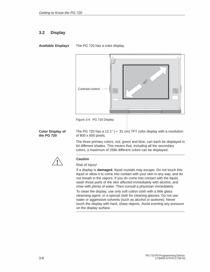
3.2 Display
The PG 720 has a color display.
Contrast control
Figure 3-4 PG 720 Display
The PG 720 has a 12.1” (� 31 cm) TFT color display with a resolutionof 800 x 600 pixels.
The three primary colors, red, green and blue, can each be displayed in64 different shades. This means that, including all the secondarycolors, a maximum of 256k different colors can be displayed.
!Caution
Risk of injury!
If a display is damaged , liquid crystals may escape. Do not touch thisliquid or allow it to come into contact with your skin in any way, and donot breath in the vapors. If you do come into contact with the liquid,wash those parts of the skin affected immediately with alcohol, andrinse with plenty of water. Then consult a physician immediately.
To clean the display, use only soft cotton cloth with a little glasscleansing agent, or a special cloth for cleaning glasses. Do not usewater or aggressive solvents (such as alcohol or acetone). Nevertouch the display with hard, sharp objects. Avoid exerting any pressureon the display surface.
Available Displays
Color Display ofthe PG 720
Getting to Know the PG 720

3-9PG 720 PII Programming DeviceC79000-G7076-C756-02
3.3 Keyboard
The keyboard is divided into the following areas:
� Alphanumeric or typewriter keyboard with special keys
� LED displays
� Function keys
� Cursor control keys.
Esc F1 F2 F3 F4 F5 F6 F7 F8 F10 Print Pause
BreakSysRq
F11 F12
���
Q W E R T Y U I O P Ü{
Home
Page
Page
End
A S D F G H J K L Ö ÄCapsLock
1 2 3 4 5 6 7{ 8 9 0 – ß =! @ ” # � $ % ^ & & / * ( ( ) ) = __?
Ctrl Alt Alt Gr
Z Y X C B N M m< ;
,> :.
? >< V
nInsert
Delete
@ [*}
] +
:
;’”
\
|
#
}[~
~
+
4
3
1
F9
Num Scroll
1 Alphanumeric keyboard
2 Special keys
3 Function keys
4 Cursor control keys
2
5
5 LED display
2
Figure 3-5 Keyboard Layout
All the keys on the keyboard are of the autorepeat type. The characteris repeated as long as the key is pressed.
The keyboard has international and German labeling.
International
Shift
Unshift
NationalExample: German
Font size and thicknessreduced
?
ß\Together with the ALTGR key
Figure 3-6 The Keyboard Labeling System
Keyboard Layout
Repeat Function
Keyboard Labeling
Getting to Know the PG 720

3-10PG 720 PII Programming Device
C79000-G7076-C756-02
The largest block of keys on the keyboard is the alphanumeric keyboardwith all the keys for the letters of the alphabet, numerals and specialcharacters. The characters are arranged in basically the same way as ona normal typewriter. However, there are a number of special keys whichhave special functions for the PG 720.
The special keys in the alphanumeric keyboard have the followingfunctions:
Table 3-5 Functions of the Special Keys
�� ��������
Backspace Key
This key moves the cursor one space to the left and deletes thecharacter at this position.
Enter
Enter Key
(Return, Enter, Line Feed (“New Line”)
The return or enter key is used mainly to terminate a commandline in the operating system; that is, the command you havetyped in is executed when you press this key. For other uses ofthis key, please refer to the user manual of the relevant userprogram.
Caps
Lock
CAPS LOCK Key
If you press this key, the middle LED at the top right-handcorner of your keyboard lights up. All upper case charactersand other characters are output normally. If you want to typelower case letters in this position, you must first press the shiftkey.
If you are using an international keyboard, you cancel thisfunction by pressing the CAPS LOCK key again. The LED thengoes out.
If you have a German keyboard, you must press the shift $ keyto cancel this function.
F9
NUM Key
With these keys Fn+ ^ NUM , the emulated numeric block isswitched from the alphanumeric keyboard to numeric keys. TheLED display lights up. Press this key again to return to cursorcontrol.
Tabulator Key
This moves the cursor depending on the selected tabulatorpositions.
AlphanumericKeyboard
Special Keys
Getting to Know the PG 720

3-11PG 720 PII Programming DeviceC79000-G7076-C756-02
Table 3-5 Functions of the Special Keys
�� ��������
“Fn” Special Key (combination key)
In conjunction with a second key (key combination), youactivate other key codes for special applications with this key.This key is also used to emulate the numeric keypad (Figure3-8 Numeric Keypad).
n
Ctrl
CTRL Key (combination key)
This key is only used in combination with other keys. Forexample, you press CTRL + ALT + Delete to reset and restartthe operating system. For other uses of this key, please refer tothe user manual of the relevant user program.
Alt
ALT Key (combination key)
This key is only used in combination with other keys. Forexample, you can enter the hexadecimal value of an ASCIIcharacter using this key and the numeric keypad for example,Fn + ALT + 123 corresponds to “{”.
AltGr
ALTGr Key (combination key)
You can use this key together with the other combination keysto generate other key codes. For example, you can generatethe “\” character on the German keyboard by typing ALTGr + ß.
PrintSysRq
PRINT (combination key)
Using the Print key, you can output the current screen displayto a printer (depending on the software used).
PauseBreak
PAUSE (combination key)
The Pause key interrupts program execution in the majority ofapplications.
The LED displays for the keys NUM LOCK and SCROLL LOCK arelocated below the function keys F9 to F12 and display the currentstatus of the keys.
� NUM LOCK
� CAPS LOCK
� SCROLL LOCK
When the programming device is powered up, the LED displays for theNUM LOCK, CAPS LOCK, and SCROLL LOCK keys light up briefly twice.The keyboard is then ready for operation.
LED Displays
Getting to Know the PG 720
3-12PG 720 PII Programming Device
C79000-G7076-C756-02
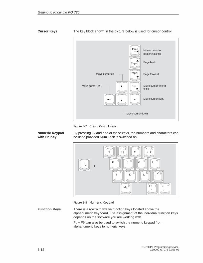
The key block shown in the picture below is used for cursor control.
Move cursor to beginning of file
Move cursor up
Move cursor right
Move cursor left
Move cursor down
Move cursor to end of file
Page back
Page forward
Home
Page
Page
End
Figure 3-7 Cursor Control Keys
By pressing Fn and one of these keys, the numbers and characters canbe used provided Num Lock is switched on.
n +U I O P
J K L Ö
7{ 8 9 0& / * ( ( ) ) =
M � ?
:;
}[
> :.
Figure 3-8 Numeric Keypad
There is a row with twelve function keys located above thealphanumeric keyboard. The assignment of the individual function keysdepends on the software you are working with.
Fn + F9 can also be used to switch the numeric keypad fromalphanumeric keys to numeric keys.
Cursor Keys
Numeric Keypadwith Fn Key
Function Keys
Getting to Know the PG 720
3-13PG 720 PII Programming DeviceC79000-G7076-C756-02
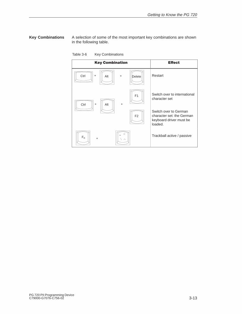
A selection of some of the most important key combinations are shownin the following table.
Table 3-6 Key Combinations
��������� �� �����
Ctrl + Alt + Delete Restart
Ctrl + Alt +
F1
F2
Switch over to internationalcharacter set
Switch over to German character set: the German keyboard driver must beloaded.
Fn +~ Trackball active / passive
Key Combinations
Getting to Know the PG 720

3-14PG 720 PII Programming Device
C79000-G7076-C756-02
3.4 Trackball
The trackball is a pointing device for cursor control and menu selectionin many programs that support mouse operation. By moving thetrackball, the cursor can be positioned anywhere on the screen.
By pressing the left-hand button, you set a marker. The function of theright-hand button depends on the particular program you are using. Youcan select objects or items in a menu and start functions with thetrackball.
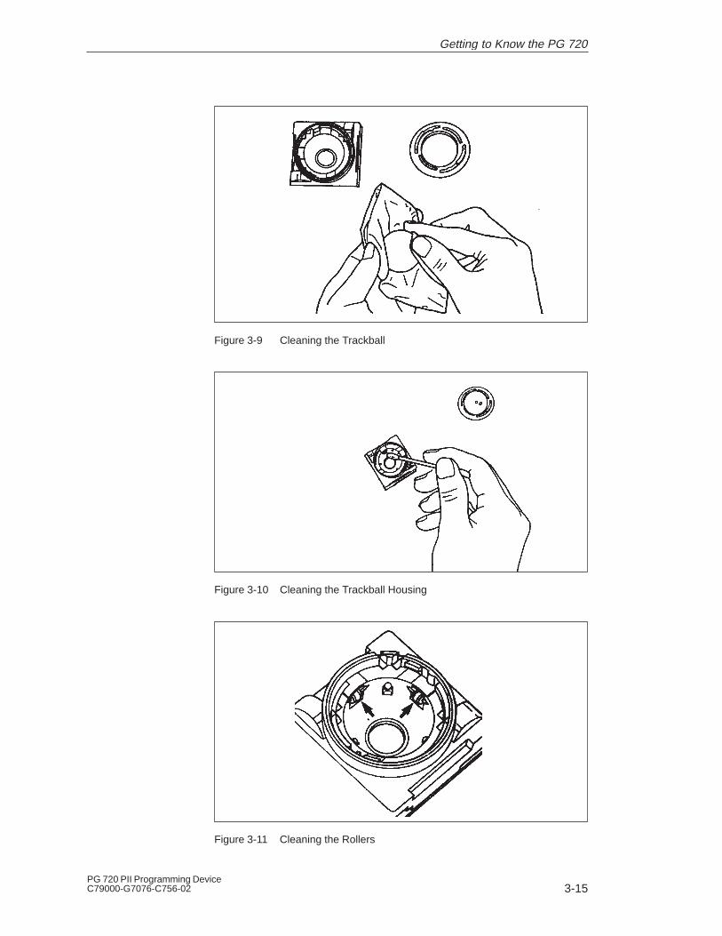
The trackball is in a roller housing which normally prevents dustcollecting on the ball or transmission mechanism. Nevertheless, youshould clean the trackball at regular intervals.
To clean the trackball, proceed as follows:
1. Switch off your programming device.
2. Remove the cover of the trackball housing by turning itanti-clockwise, for example by inserting tweezers or a similar toolinto the holes in the ring.
3. You can now take the trackball out of its housing.
4. Wash the trackball in a solution of tap water and mild cleansingagent.
5. Blow any residual dust out of the trackball housing.
6. Dry the trackball and return it to its housing.
7. Replace the cover and tighten it by turning it in a clockwisedirection.
Trackball
Cleaning theTrackball
Getting to Know the PG 720
3-15PG 720 PII Programming DeviceC79000-G7076-C756-02
Figure 3-9 Cleaning the Trackball
Figure 3-10 Cleaning the Trackball Housing
Figure 3-11 Cleaning the Rollers
Getting to Know the PG 720
3-16PG 720 PII Programming Device
C79000-G7076-C756-02
3.5 Drives
The PG 720 is equipped with the following drives as standard:
Table 3-7 Standard Drives
Type of Drive Format Capacity
Floppy (diskette) drive 3.5 inch 1.44 Mbytes
Hard disk drive 2.5 inch See Product Informationleaflet
Using the floppy disk drive, you can save programs and data ondiskettes and load them on the PG 720.
You can use the following diskettes:
Table 3-8 Types of Diskette
Double-Sided High-Density Diskette
Double-Sided Double-Density Diskette
3.5 inch 3.5 inch
1.44 Mbytes (135 TPI) 720 Kbytes
80 tracks per side 80 tracks per side
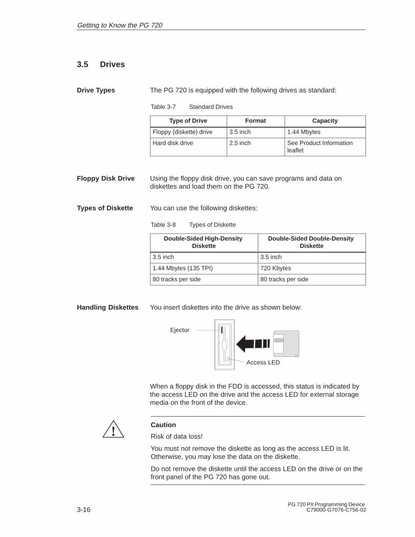
You insert diskettes into the drive as shown below:
Access LED
Ejector
When a floppy disk in the FDD is accessed, this status is indicated bythe access LED on the drive and the access LED for external storagemedia on the front of the device.
!Caution
Risk of data loss!
You must not remove the diskette as long as the access LED is lit.Otherwise, you may lose the data on the diskette.
Do not remove the diskette until the access LED on the drive or on thefront panel of the PG 720 has gone out.
Drive Types
Floppy Disk Drive
Types of Diskette
Handling Diskettes
Getting to Know the PG 720
3-17PG 720 PII Programming DeviceC79000-G7076-C756-02
You can use a number of different hard disk drives in your PG 720. Thememory capacity of the particular type of hard disk can be found in theProduct Information Bulletin and SETUP program.
When the hard disk is accessed, this status is indicated by the access LEDfor external storage media on the front of the device.
!Caution
Risk of data loss and damage to drive!
Drives are sensitive to vibrations and shock. Any vibrations occurringduring operation can lead to the loss of data or damage to the drive.
After switching off, wait a moment until the drive has stopped spinning(approximately 10 sec.) before you move the programming device.
Hard Disk Drive
Getting to Know the PG 720

3-18PG 720 PII Programming Device
C79000-G7076-C756-02
3.6 CD-ROM Drive
You can use the CD-ROM drive to read information from CDs into thePG 720. The CD-ROM drive is installed at the back of the PG 720. It isoperated on the same port as the hard disk drive.
Swing the PG 720 into a horizontal position. The CD-ROM drive is nowon the underside of the programming device. Switch the device on. Bybriefly pressing the eject button, the drawer springs out slightly. Nowpull the drawer out until it clicks into position.
Now insert the CD in the drawer with the labeling face up, and press itfirmly down into the center of the turntable. To remove the CD, hold itby the edges and pull upwards.
Push in the drawer until it closes completely. Do not press the ejectbutton.
Note
To ensure that the open drawer of the CD-ROM drive is not exposed toexcessive strain, always use one hand to hold the front of the drawerwhile inserting or removing a CD-ROM with the other.
Some applications support an EJECT function for opening theCD-ROM drive: this function does not work with this drive.The CD is tested when you close the drive and the access LED on thedrive flashes to indicate that the test is in progress:– if the LED does not stop flashing the CD is bad but readable,– if the LED flashes several times and then remains on, the CD is not
readable and defective.
1 Access LED2 Drawer3 Eject button4. Emergency release
12 3 4
!CautionRisk of data loss and damage to the drive.
CD-ROM drives are very sensitive to impermissible vibration. Vibrationduring operation can result in damage to the drive or the CD.
Overview
Opening theDrawer
Inserting /Removing CDs
Closing the Drawer
Front Panel ofthe CD-ROMDrive
Getting to Know the PG 720

3-19PG 720 PII Programming DeviceC79000-G7076-C756-02
3.7 External Power Unit and Battery
The external power unit is used to supply the PG 720 with power whenit is being operated with 120 V or 230 V mains supplies. The voltagerange is set automatically. In mains power supply operation, theintegrated battery is charged at the same time. The connecting cable tothe PG 720 has an external power supply unit. For connection to thepower system, the external power supply unit has a connector fornon-heating appliances.
LED-Display
Figure 3-12 External Power Unit
!Caution
Danger of overheating!
The external power supply unit can be damaged if it is covered.
!Caution
Risk of damage!
The PG 720 can only be used with supplied mains adapter.
The PG 720 has an integrated NiMH (nickel metal hydride)rechargeable battery. This makes the device portable, meaning youcan use it without the external power supply. The battery also preventsdata loss occurring on power failure.
Once the external power supply unit is connected, the battery ischarged. The following conditions are important:
� When charging, the battery temperature must be between + 5° Cand + 40° C (40° F and 100° F).
� When the device is switched off, charging takes approximately2 hours (fast charging).
� When the device is switched on, charging takes approximately8 hours (reduced charging current).
External PowerUnit
Battery
Getting to Know the PG 720
3-20PG 720 PII Programming Device
C79000-G7076-C756-02
� Charging stops as soon as the battery is fully charged.
� In storage, a fully charged battery runs down in approximately2 months. It must then be recharged.
� The battery has an integral charge-status monitor (”fuel gauge”).
� You can check the battery charge level in Windows 98.See Section 4.2 Battery Mode.
� It is advisable to run a teach-in cycle every now and again (see Section 4.2).
Note
The green ”Battery” LED does not necessarily mean that the battery isfully charged. Charging is cut short for safety reasons if the batterytemperature drops below 5°C or rises above 40°C.
Whenever possible, avoid running down the battery too far. Switch offthe unit when it is not in use and remove the battery connector (seeSection 4.2) if it will not be used for some time (weeks).
The Battery LED goes red and an acoustic warning sounds if thebattery is in danger of discharging fully (see Section 4.2)
Bear in mind that you must unplug the a.c. cord from the mains socketin order to disconnect the programming device from the mains supply.
3.8 Sound
The programming device has two built-in speakers. You can adjust theoutput volume either by clicking the Loudspeaker button in the taskbaror by opening the Start menu in Windows and selecting Programs >Accessories > Multimedia > Volume .
Getting to Know the PG 720
4-1PG 720 PII Programming DeviceC79000-G7076-C756-02
Installing and Operating the PG 720
This chapter describes what you have to do to set up your PG 720correctly for operation. This includes:
� The basic steps for commissioning your PG 720
� Working in the battery mode and changing the battery
� Working with memory submodules and cards for the programmablelogic controllers
� Connecting your PG 720 to other devices.
Section Contents Page
4.1 Connecting the PG 720 to the Power Supply 4-2
4.2 Battery Operation 4-3
4.3 Connecting I/O Devices 4-7
4.4 Working with SIMATIC S5 Memory Submodules 4-12
4.5 Working with SIMATIC Memory Cards 4-14
4.6 Working with PC cards 4-15
4.7 Connecting the PG 720 to other SIMATIC S5 Units 4-17
4.8 Connecting the PG 720 to a SIMATIC S7 Network(MPI/DP)
4-21
4.9 Networking the PG 720 with Other Stations onPROFIBUS
4-23
4.10 Networking the PG 720 and Other Computers onIndustrial Ethernet
4-24
4.11 Connection under Windows 4-24
What Does ThisChapter Contain?
ChapterOverview
4

4-2PG 720 PII Programming Device
C79000-G7076-C756-02
4.1 Connecting the PG 720 to the Power Supply
You can operate the PG 720 on 120 V and 230 V power systems usingthe external power supply unit. The voltage is selected automatically.
1. Plug the power supply cable supplied with the unit into theconnector on the external power supply unit.
2. Connect the power cable to a socket outlet with a groundedprotective conductor.
3. Connect the low voltage connector to the connection for the externalpower supply on the unit. The power supply cable to the PG 720 isintegrated in the external power supply unit.
4. The device is now ready for power supply operation and the batterywill be charged if required.
Connection for externalpower unit
VN = 17.5 V DC
Figure 4-1 Power Supply Connection
Note
The power plug must be disconnected to isolate the unit completelyfrom the supply.
For operation in Canada and the US, a CSA or UL listed power supplycable must be used.
The external power supply unit is intended for operation with groundedpower supply systems (TN networks according to IEC 364-3).
The unit is not intended for operation with non-grounded orimpedance-grounded systems (IT networks).
The Power Management function can interrupt battery charging ifcurrent consumption is high while the programming device is inoperation.
Connecting to thePower Supply
Installing and Operating the PG 720
4-3PG 720 PII Programming DeviceC79000-G7076-C756-02
4.2 Battery Mode
The battery has electronic circuitry for showing the current chargestatus. The electronics incorporate a metering unit which has to becalibrated at regular intervals so that it can compensate for error. Thechemical properties of the battery change in the course of time, so theelectronics have to relearn the battery’s characteristics at regularintervals. A teach-in cycle ensures that the battery’s maximum chargecapacity is at your disposal.
Note
There is a danger of the charge-status indicator misinterpreting theactual capacity of the battery if a lengthy period of time is allowed topass between teach-in cycles. This can result in an unexpectedshutdown with no prior warning.
Run a teach-in cycle:
� once every month,
� if a prolonged period of time has elapsed since the battery was lastused,
� if you think that the battery no longer operates at full capacity,
� if the programming device shuts down unexpectedly with no priorwarning,
� if operating time on battery becomes shorter.
� If during startup the error message “Battery needs calibrationcycle” appears (has to be acknowledged with the F1 key).
Broadly speaking, the procedure for a teach-in cycle is as follows:
� Charge the battery until the charge-status indicator shows 100%.See the section entitled ”Displaying Charge Status” for instructionson how to view the indicator.
� Leave the programming device switched on to drain the battery: theprogramming device will switch itself off when the battery isdischarged. Remember to disconnect the power unit from thePG 720 so that the battery can discharge.
� Once the programming device has switched itself off, start anothercharge cycle by reconnecting the external power unit to the PG 720.The teach-in cycle terminates automatically approximately 10minutes later.
Charge-Status Indicator
Teach-in Cycle (calibration cycle)
Performing aTeach-in Cycle
Installing and Operating the PG 720

4-4PG 720 PII Programming Device
C79000-G7076-C756-02
Note
You can speed up the discharge stage by deactivating the Powermanagement functions in the BIOS (see Setup menu, Section 6.1.4Power Savings Disabled....). Under Windows 98 you can achieve thefastest possible discharge by clicking Taskbar > Start > Settings >Energy Management > Energy Schematics > Settings for EnergySchematics > Battery Mode and entering ’Never’ in all categories.
The battery charge status is shown in the Summary screen (seeFigure 6-6). You can freeze this screen for viewing by hitting the Pausekey as soon as the Summary screen appears as the programmingdevice powers up.
Windows 98 has a convenient feature for viewing the battery chargestatus. To check the battery charge status: Taskbar > Start > Settings> Energy Management > Battery Indicator.
If no external power unit is connected, the PG 720 can operate on thebuilt-in rechargeable battery.
1. Switch on the programming device. Check that the battery isadequately charged before you start work.
Note
The battery charge status is displayed in the Summary screen at theend of the system boot phase; you can also check the charge statusunder Windows 98.
2. Work with your PG 720 in the usual way.
3. When the Battery LED turns red in battery mode, the battery hasdischarged to a minimal residual-charge level. Save your data andclose your work session.
Displaying ChargeStatus
Battery Mode
Installing and Operating the PG 720

4-5PG 720 PII Programming DeviceC79000-G7076-C756-02
Note
Do not start a work session in battery mode unless the battery is fullycharged. This is the only way of ensuring that the full on-batteryoperating time is available; note that if the Battery LED is orange whenyou switch on with the programming device is connected to the a.c.mains supply, the battery is recharging.
The battery is not recharging if the Battery LED is green. The green”Battery” LED does not necessarily mean that the battery is fullycharged. Charging is interrupted if, for example, battery temperature istoo high.
You may find that the battery is partially or fully discharged when youswitch on the programming device (because it has drained graduallywhile not in use, for example). Use the external power unit to connectthe programming device to the a.c. mains supply so that the batterycan recharge.
The battery recharges as soon as the programming device isconnected to the a.c. mains supply by means of the external powerunit: the battery recharges in fast-charge mode if the programmingdevice remains switched off (this takes about 2 hours) or in about eighthours at reduced charge current if the programming device is switchedon.
You can remove a discharged or defective battery and install areplacement (see the Operating Instructions for the order number):
1. Switch off the programming device.
2. Pull out the support in the stand and open the extra support hoop.
3. Turn the housing through approximately 90°.
4. Slide the cover in the underside of the housing down to open thebattery compartment.
5. Unplug the battery connector and lift out the battery.
6. Slip the new battery into position and reconnect the cable.
7. Close the battery-compartment cover.
Changing the Bat-tery
Installing and Operating the PG 720

4-6PG 720 PII Programming Device
C79000-G7076-C756-02
Unlocking thebattery connector- press here
1 Battery connector
2 Akku
3 Pull out Support
4 Akku compartment cover
1
2
3
4
2
Figure 4-2 Changing the Akku
Note
Whenever possible, avoid running down the batterie to a low level.Switch off the device after use. If the device will not be used for sometime (for example, several weeks), you should remove the batteryconnector. The batterie then has no connection to the device and inthis way can be optimally saved for future use.
Nickel-metal hydride batteries can be recycled. Their components canbe used as raw materials for new batteries or other products. Effectiverecycling of batteries is only possible when the used batteries arecollected according to type.
Note
Observe the local regulations for disposal of materials.
Disposal of UsedBatteries
Installing and Operating the PG 720

4-7PG 720 PII Programming DeviceC79000-G7076-C756-02
4.3 Connecting I/O Devices
To connect your printer, proceed as follows:
1. Switch off the PG 720 and the printer.
2. Open the cover to the interface ports on the left-hand side panel.
3. Plug the printer cable into the LPT1 parallel port.
4. Connect the printer cable to the printer.
5. Screw the connector tight at the interface port.
COM 2
COM 1 LPT 1(parallel)
(serial)
(serial)
port
socket socket
Figure 4-3 Position of the Printer Ports
!Caution
Risk of damage to the unit!
Switch the unit off before connecting the parallel printer to the LPT 1port (the printer should also be switched off).
Make sure that you use the correct port. If you use the wrong portor wrong connecting cables, the port may be damaged.
Before plugging in the cables, the electrostatic charge of your body, theunit, and the cables must be equalized. To do this, touch the mountingplate for the ports on the left-hand side of the unit.
Only use original connecting cables.
Connecting thePrinter to theParallel Port
Installing and Operating the PG 720

4-8PG 720 PII Programming Device
C79000-G7076-C756-02
You can also connect your printer to the PG 720 using a serial COM port.You will find information on how to adapt and set your interface and whichconnecting cable you require in the description of your printer.
You connect external multisynchronous monitors using the standardVGA connector on the left-hand panel side of the unit. We recommendthat you use a Siemens monitor.
VGA socket
Figure 4-4 Connecting the Monitor
You must switch the PG 720 off before connecting the monitor cable.You will find further information about the connector pinout inChapter 8.To connect the monitor, proceed as follows:
1. Switch off the PG 720 and the monitor.
2. Open the port cover on the left-hand side panel.
3. Plug the monitor cable into the VGA socket connector.
4. Secure the connector with the screws.
5. Plug the other end of the monitor cable into the monitor.
6. Switch on the PG 720 and the monitor.
7. Make the necessary changes in the SETUP program (Menu > Main> Hardware Options “CRT enabled”, “LCD enabled” “SIMULTAN”).
!Caution
Danger of damaging the monitor!
If you want to set higher clock frequencies and resolutions, first makesure that the monitor you are using is suitable for a higher clockfrequency and resolution.
If the clock frequency is too high, this can cause damage to the monitor.
Connecting thePrinter to theSerial Port
RecommendedMonitors
ConnectingMonitors
Installing and Operating the PG 720
4-9PG 720 PII Programming DeviceC79000-G7076-C756-02
You can connect both a PS/2–USB and a serial mouse to the PG 720.When the PG 720 is supplied, the mouse driver for the trackball andPS/2 mouse is already loaded.
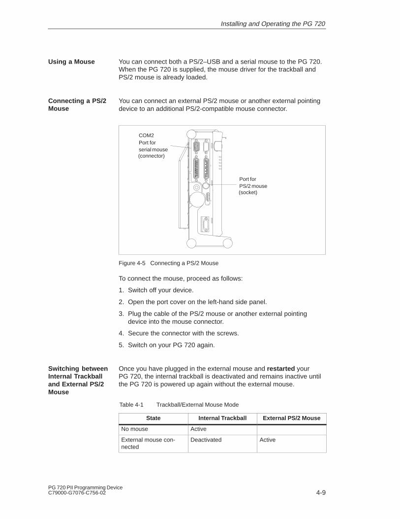
You can connect an external PS/2 mouse or another external pointingdevice to an additional PS/2-compatible mouse connector.
COM2
PS/2 mouse
Port for
Port for
serial mouse(connector)
(socket)
Figure 4-5 Connecting a PS/2 Mouse
To connect the mouse, proceed as follows:
1. Switch off your device.
2. Open the port cover on the left-hand side panel.
3. Plug the cable of the PS/2 mouse or another external pointingdevice into the mouse connector.
4. Secure the connector with the screws.
5. Switch on your PG 720 again.
Once you have plugged in the external mouse and restarted yourPG 720, the internal trackball is deactivated and remains inactive untilthe PG 720 is powered up again without the external mouse.
Table 4-1 Trackball/External Mouse Mode
State Internal Trackball External PS/2 Mouse
No mouse Active
External mouse con-nected
Deactivated Active
Using a Mouse
Connecting a PS/2Mouse
Switching betweenInternal Trackballand External PS/2Mouse
Installing and Operating the PG 720
4-10PG 720 PII Programming Device
C79000-G7076-C756-02
You can connect a serial mouse to the COM2 serial port. To operate aserial mouse, the appropriate mouse driver must be initialized andassigned parameters. You will find the information you need to do thisin the description of your mouse or in the description of the operatingsystem.
1. Switch off your device.
2. Open the cover of the interface ports on the left-hand side panel.
3. Plug the serial mouse into the mouse connector labeled COM2.
4. Secure the connector with the screws.
5. Switch on your PG 720 again.
6. Connect external mouse to USB interface.
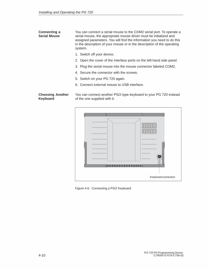
You can connect another PS/2-type keyboard to your PG 720 insteadof the one supplied with it.
Keyboard connection
Figure 4-6 Connecting a PS/2 Keyboard
Connecting aSerial Mouse
Choosing AnotherKeyboard
Installing and Operating the PG 720
4-11PG 720 PII Programming DeviceC79000-G7076-C756-02
To connect the keyboard, proceed as follows:
1. Switch off your device.
2. Unplug the keyboard connector from the base of the unit.
3. Plug in the PS/2-type keyboard connector.
Note
It is advisable to use a keyboard cable with an angled connector, sothat the connector does not extend beyond the back panel.
The keyboard cable must be inserted in the cable conduit on the backpanel of the unit, otherwise the connector can work loose when thedevice is tilted.
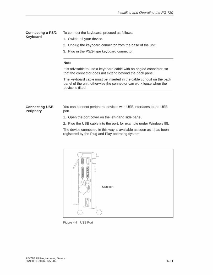
You can connect peripheral devices with USB interfaces to the USBport.
1. Open the port cover on the left-hand side panel.
2. Plug the USB cable into the port, for example under Windows 98.
The device connected in this way is available as soon as it has beenregistered by the Plug and Play operating system.
USB port
Figure 4-7 USB Port
Connecting a PS/2Keyboard
Connecting USBPeriphery
Installing and Operating the PG 720
4-12PG 720 PII Programming Device
C79000-G7076-C756-02
4.4 Working with SIMATIC S5 Memory Submodules
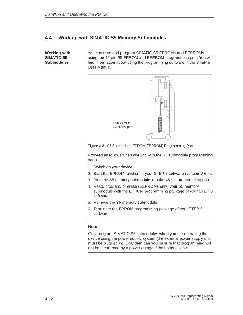
You can read and program SIMATIC S5 EPROMs and EEPROMsusing the 48-pin S5 EPROM and EEPROM programming port. You willfind information about using the programming software in the STEP 5User Manual.
S5 EPROM/EEPROM port
Figure 4-8 S5 Submodule (EPROM/EEPROM) Programming Port
Proceed as follows when working with the S5 submodule programmingports:
1. Switch on your device.
2. Start the EPROM function in your STEP 5 software (version V 6.x).
3. Plug the S5 memory submodule into the 48-pin programming port.
4. Read, program, or erase (EEPROMs only) your S5 memorysubmodule with the EPROM programming package of your STEP 5software.
5. Remove the S5 memory submodule.
6. Terminate the EPROM programming package of your STEP 5software.
Note
Only program SIMATIC S5 submodules when you are operating thedevice using the power supply system (the external power supply unitmust be plugged in). Only then can you be sure that programming willnot be interrupted by a power outage if the battery is low.
Working withSIMATIC S5Submodules
Installing and Operating the PG 720

4-13PG 720 PII Programming DeviceC79000-G7076-C756-02
!Caution
Risk of damage to EPROMs or EEPROMs!
If you insert or remove the EPROM or EEPROM while it is in use,there is a danger that it will be damaged.
You must not remove the S5 EPROM or EEPROM while the LEDindicating that the EPROM or EEPROM is being read etc. is lit. Youcannot work simultaneously with S5 memory submodules andmemory cards.
Before inserting or removing S5 EPROMs or EEPROMs, you mustequalize the static charge on your body with the potential on the unit.You can do this by briefly touching the metal mounting plate of theports on the left-hand side panel of the unit.
Installing and Operating the PG 720
4-14PG 720 PII Programming Device
C79000-G7076-C756-02
4.5 Working with SIMATIC Memory Cards
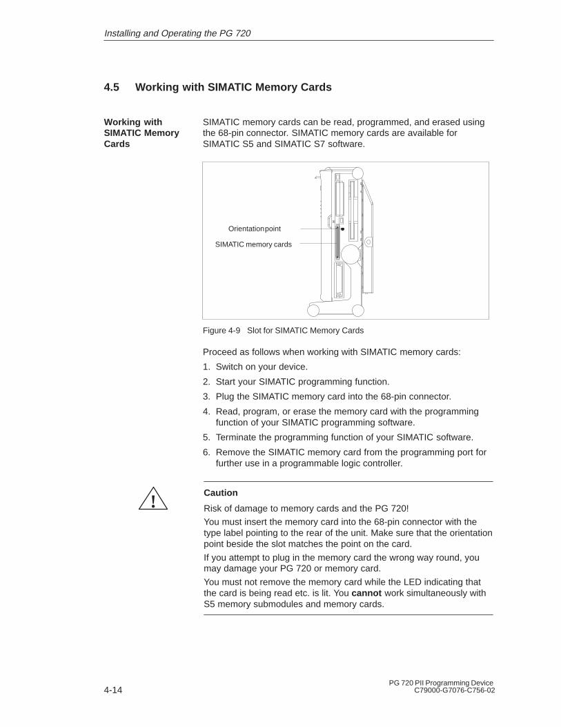
SIMATIC memory cards can be read, programmed, and erased usingthe 68-pin connector. SIMATIC memory cards are available forSIMATIC S5 and SIMATIC S7 software.
SIMATIC memory cards
Orientation point
Figure 4-9 Slot for SIMATIC Memory Cards
Proceed as follows when working with SIMATIC memory cards:
1. Switch on your device.
2. Start your SIMATIC programming function.
3. Plug the SIMATIC memory card into the 68-pin connector.
4. Read, program, or erase the memory card with the programmingfunction of your SIMATIC programming software.
5. Terminate the programming function of your SIMATIC software.
6. Remove the SIMATIC memory card from the programming port forfurther use in a programmable logic controller.
!Caution
Risk of damage to memory cards and the PG 720!
You must insert the memory card into the 68-pin connector with thetype label pointing to the rear of the unit. Make sure that the orientationpoint beside the slot matches the point on the card.
If you attempt to plug in the memory card the wrong way round, youmay damage your PG 720 or memory card.
You must not remove the memory card while the LED indicating thatthe card is being read etc. is lit. You cannot work simultaneously withS5 memory submodules and memory cards.
Working withSIMATIC MemoryCards
Installing and Operating the PG 720

4-15PG 720 PII Programming DeviceC79000-G7076-C756-02
4.6 Working with PC Cards
The PC card interface supports Cardbus cards (32-bit) and PCMCIAcards (16-bit). The PG 720 has two PC card ports. You can plugcommunication modules for MODEM, FAX-MODEM, ISDN, TokenRing, ETHERNET, memory expansion and SCSI interface modules incredit-card format into these ports. You can plug in two type II cards orone type III card.
Ejector for PC cards
PC card interface, type I/II
PC card interface, type I/II/III
(slot 1)
(slot 2)
Figure 4-10 PC Card Interface
!Caution
Risk of damage to PC cards and the PG 720!
Always insert PC cards with the front face turned toward the rear ofthe PG 720. The front face generally bears the company and productdesignation and is labeled ”This side up”, or words to that effect.
You might damage the PG 720 and the PC card if you attempt to insertthe PC card the wrong way round.
Always discharge your body’s charge of static electricity by brieflytouching a grounded part of the device (e.g. the metal mount of theport) before inserting or removing a card (in accordance with theinstructions for handling electrostatically sensitive components)
PC Cards
Installing and Operating the PG 720
4-16PG 720 PII Programming Device
C79000-G7076-C756-02
Note
Do not use PC cards along with a SIMATIC-S5 module or a SIMATICmemory card. Always follow the instructions in your OperatingInstructions.
Note
In order to use a PC card you must enter BIOS-SETUP, open the Mainmenu, select the Hardware Option submenu and set “Cardbus/PCMCIA Slot” to “Enabled”.
Installing and Operating the PG 720
4-17PG 720 PII Programming DeviceC79000-G7076-C756-02
4.7 Connecting the PG 720 to other SIMATIC S5 Units
In this section, you will learn how to connect your PG 720 to aprogramming device or S5 programmable logic controller using apoint-to-point connection.
You can establish a point-to-point connection by connecting the PG 720to another programming device or a programmable logic controllerusing
� An RS-232 connection
� A TTY connection
To ensure reliable data transfer, several factors must be taken intoaccount. The maximum data transfer rate (baud rate) depends on thedistance, the type of cable, the pin assignment of the interface andexternal interference.
You can reduce interference by choosing the right transmission cable andconnecting it properly, and by observing the following guidelines:
� Use a shielded cable with a low line resistance (130 � / km) (about40�� kft) and low capacitance (< 90 pF/m) (about 27 pF/ft).Twisted-pair cables are less susceptible to noise and interference. Alow line resistance results in reduced voltage excursions and shortercharge reversal times. The line resistance decreases with increasingconductor cross-section for the same length of cable.
� The shorter the transmission link, the higher the maximum possibledata transfer rate.
� If there is an active sender and an active receiver at the same end ofthe transmission link, the sequence of access priority to thetransmission circuit must be taken into account in order to achieve thelongest possible transmission link.
� Signal lines and power lines must not run together. Signal lines mustbe installed as far away as possible from sources of strong interference(for example, 400 V 3-phase power cables).
� The active TTY interface with a 12 V no-load voltage has been testedon a 100 m (1100 ft) long cable at a transmission rate of 9600 bps inan environment with normal levels of noise (field strength < 3 V/m or1 V/ft). If a shielded LiYCY 5 x 1 x 0.14 shielded cable is used, reliabletransmission is possible over a distance of up to 100 m (1100 ft). TheAS511 protocol (only one transmitter at a time) was used for testing.
Note
The interference field of the source decreases exponentially with thedistance.
Point-To-PointConnection
ConfiguringInterfaces withLine Current (TTY, 20 mA)
Rules
Installing and Operating the PG 720
4-18PG 720 PII Programming Device
C79000-G7076-C756-02
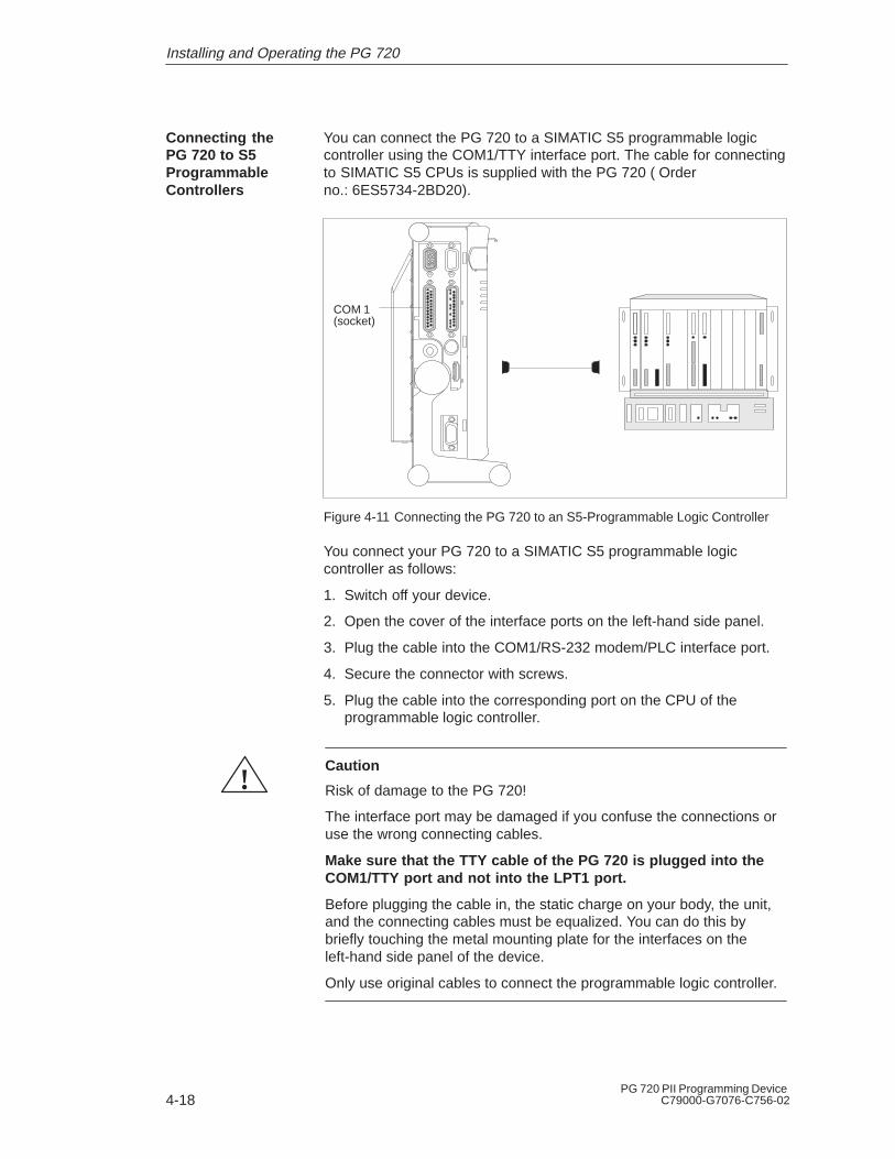
You can connect the PG 720 to a SIMATIC S5 programmable logiccontroller using the COM1/TTY interface port. The cable for connectingto SIMATIC S5 CPUs is supplied with the PG 720 (�Orderno.:�6ES5734-2BD20).
COM 1(socket)
Figure 4-11 Connecting the PG 720 to an S5-Programmable Logic Controller
You connect your PG 720 to a SIMATIC S5 programmable logiccontroller as follows:
1. Switch off your device.
2. Open the cover of the interface ports on the left-hand side panel.
3. Plug the cable into the COM1/RS-232 modem/PLC interface port.
4. Secure the connector with screws.
5. Plug the cable into the corresponding port on the CPU of theprogrammable logic controller.
!Caution
Risk of damage to the PG 720!
The interface port may be damaged if you confuse the connections oruse the wrong connecting cables.
Make sure that the TTY cable of the PG 720 is plugged into theCOM1/TTY port and not into the LPT1 port.
Before plugging the cable in, the static charge on your body, the unit,and the connecting cables must be equalized. You can do this bybriefly touching the metal mounting plate for the interfaces on theleft-hand side panel of the device.
Only use original cables to connect the programmable logic controller.
Connecting thePG 720 to S5ProgrammableControllers
Installing and Operating the PG 720
4-19PG 720 PII Programming DeviceC79000-G7076-C756-02
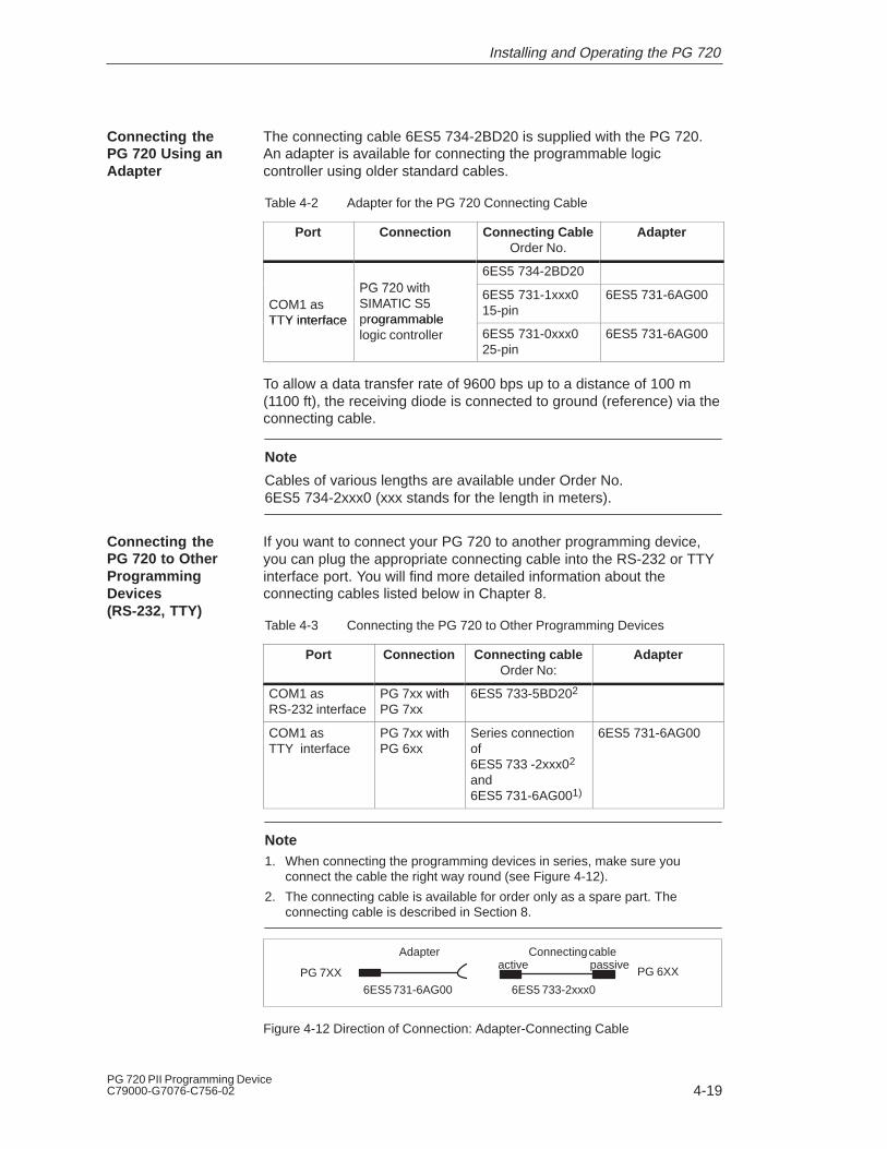
The connecting cable 6ES5 734-2BD20 is supplied with the PG 720.An adapter is available for connecting the programmable logiccontroller using older standard cables.
Table 4-2 Adapter for the PG 720 Connecting Cable
Port Connection Connecting CableOrder No.
Adapter
PG 720 ith6ES5 734-2BD20
COM1 asTTY interface
PG 720 withSIMATIC S5programmable
6ES5 731-1xxx015-pin
6ES5 731-6AG00
TTY interface rogrammablelogic controller 6ES5 731-0xxx0
25-pin6ES5 731-6AG00
To allow a data transfer rate of 9600 bps up to a distance of 100 m(1100 ft), the receiving diode is connected to ground (reference) via theconnecting cable.
Note
Cables of various lengths are available under Order No. 6ES5 734-2xxx0 (xxx stands for the length in meters).
If you want to connect your PG 720 to another programming device,you can plug the appropriate connecting cable into the RS-232 or TTYinterface port. You will find more detailed information about theconnecting cables listed below in Chapter 8.
Table 4-3 Connecting the PG 720 to Other Programming Devices
Port Connection Connecting cableOrder No:
Adapter
COM1 as RS-232 interface
PG 7xx with PG 7xx
6ES5 733-5BD202
COM1 asTTY interface
PG 7xx with PG 6xx
Series connectionof6ES5�733�-2xxx02
and6ES5�731-6AG001)
6ES5 731-6AG00
Note1. When connecting the programming devices in series, make sure you
connect the cable the right way round (see Figure 4-12).
2. The connecting cable is available for order only as a spare part. Theconnecting cable is described in Section 8.
Adapter Connecting cableactive passive
6ES5 731-6AG00 6ES5 733-2xxx0
PG 7XX PG 6XX
Figure 4-12 Direction of Connection: Adapter-Connecting Cable
Connecting thePG 720 Using anAdapter
Connecting thePG 720 to OtherProgrammingDevices(RS-232, TTY)
Installing and Operating the PG 720

4-20PG 720 PII Programming Device
C79000-G7076-C756-02
Note
If you connect two programming devices using the TTY interface, youmust deactivate the TTY interface (COM1) on one of the devices bychanging the jumper settings. When supplied, this interface is alwaysactive.
When your PG 720 is supplied, the COM1 (TTY) serial port is active(20 mA current loop). When you connect two programming devicesusing the COM1 (TTY) serial port, you must deactivate the port on oneof these devices. The PG 720 has jumpers on the mother board for thispurpose.
These jumpers are accessible if you open the battery compartmentcover.
Change the jumper settings as shown in Figure 4-13.
TTY receiveTTY send
deactivated
activated1 2 3 4 5
1 2 3 4 5
TTY receiveTTY send, open
Figure 4-13 Activating, Deactivating the TTY Port using jumpers
Proceed as follows to deactivate the port on the PG 720:
1. Switch off your device.
2. Adjust the position of the PG 720 so that it is horizontal.
3. Open the battery compartment cover.
4. Remove jumpers 2-3 and 4-5 at the top left beside the battery.
5. Insert the jumper in slot 1-2 (see Figure 4-13).
6. Close the battery compartment cover.
Activating/Deactivating thePG 720
Jumper Settings
Changing theJumper Setting
Installing and Operating the PG 720

4-21PG 720 PII Programming DeviceC79000-G7076-C756-02
4.8 Connecting the PG 720 to a SIMATIC S7 Network (MPI/DP)
You can connect your PG 720 to a SIMATIC S7 programmable logiccontroller using the floating*) MPI/DP interface. The MPI cable forconnection to SIMATIC S7 CPUs is supplied with the PG 720.(Order No.:�6ES7901-0BF00-0AA0)
6ES7901-0BF00-0AA05 m (about 16 ft.)
In a high-interference area:Bus connector6ES7972-0BB10-0XA0 or 6ES7972-0BB20-0XA06ES5762-1AA21
MPI/DP port
Figure 4-14 Connection Using the MPI/DP Interface
Proceed as follows when connecting to a SIMATIC S7 programmablelogic controller:
1. Switch off your device.
2. Open the interface cover on the left-hand side panel of the device.
3. Connect the cable to the MPI/DP interface.
!Caution
Risk of damage to the PG 720!
Before plugging in the cables, the static charge on your body, the unit,and the cables must be equalized. You can do this by briefly touchingthe metal mounting plate for the interfaces on the left-hand side panel.
*) Electrical isolation in the safety extra-low voltage circuit (SELV circuit).
Connecting an S7ProgrammableController via anMPI/DP Interface
Installing and Operating the PG 720

4-22PG 720 PII Programming Device
C79000-G7076-C756-02
Via the MPI/DP interface, you can connect your programming devicesto
� MPI networks (S7-200, S7-300, and S7-400) or
� PROFIBUS DP networks (DP components).
Up to 32 devices (PC, programming device, or programmablecontroller) can be connected to the MPI/DP interface to form a networksegment. The physical connection to the MPI/PROFIBUS DP networkis via a floating RS485 interface which is a component of theprogramming device basic module.
Several MPI/PROFIBUS DP network segments can be connected viarepeaters. The complete MPI/PROFIBUS DP network can comprise upto 127 stations. The data transmission rate in the MPI network is187.5 Kbps. Data transmission rates from 9.6 Kbps to 12 Mbps arepossible in the PROFIBUS-DP MPI network.
Note
You will find more information on setting up an MPI/DP network in themanual ”Profibus Networks” Order No.: 6GK 1970-5CA10-0AA0 or inSIMATIC NET.
Connecting
MPI/PROFIBUS DPNetwork
Installing and Operating the PG 720
4-23PG 720 PII Programming DeviceC79000-G7076-C756-02
4.9 Networking the PG 720 with Other Stations on PROFIBUS
PROFIBUS is an open and robust bus system for industrial use. It canbe used to configure networks with up to 32 stations per segment. Thedata transfer rate for PROFIBUS is 1.5 Mbps. PROFIBUS-DPsupports data-transfer rates from 9,6 Kbaud to 12 Mbaud.
The network operates on the master-slave principle with token passing(complying with DIN19245, PROFIBUS). It distinguishes betweenactive and passive stations. An active station receives the token andpasses it on to the next station within a specified time.
Using the following components, for example, you can connect ornetwork the PG 720 with PROFIBUS:
� RS 485 MPI/DP interface adapter, integrated
� Shielded, twisted pair (bus cable or connecting cable to network).
Note
You will find more detailed information about the SIMATIC Net PCcards in the SIMATIC NET Catalog IK 10.
Networking thePG 720 onPROFIBUS
How the NetworkFunctions
HardwareRequirements
Installing and Operating the PG 720

4-24PG 720 PII Programming Device
C79000-G7076-C756-02
4.10 Networking the PG 720 and Other Computers on Industrial Ethernet
Industrial Ethernet is a bus system for industrial use based onETHERNET (ISO 8802/3). The main features of Industrial Ethernet arespeed (10 Mbps), simple expansion, open communication, andwidespread application.
Industrial Ethernet is the name of Siemens networks and networkcomponents operating according to the CSMA / CD (ETHERNET)principle. Industrial Ethernet is a bus-type LAN that uses a triaxial cable(H1) as its transmission medium.
To connect or network the PG 720 with Industrial Ethernet, aPC-card-ETHERNET interface module is required.
Note
You will find more detailed information about the SIMATIC Net PCcards in the SIMATIC NET Catalog IK 10.
4.11 Connection under Windows
Windows supports point-to-point connections via the LPT or COM port.The connecting cables are standard, commercially available products.More information is available in the Networks section of the Windowsdescription and in the online Help system under “Connection to AnotherComputer”.
Networking thePG 720 onIndustrial Ethernet
How the NetworkFunctions
HardwareRequirements
Installing and Operating the PG 720
5-1PG 720 PII Programming DeviceC79000-G7076-C756-02
PG 720 Expansions
You can enhance the performance of your PG 720 by adding additionalmemory. This chapter describes how to expand your PG 720. Pleaseobserve the relevant safety guidelines.
Section Contents Page
5.1 Opening the Unit 5-2
5.2 Components Visible After Opening the Unit 5-4
5.3 Block Diagram of the Motherboard 5-5
5.4 Switch Setting / Jumper 5-7
5.5 Installing Memory Expansion Modules 5-8
5.6 Processor Upgrade 5-9
5.7 Replacing the Backup Battery 5-10
5.8 Closing the Unit 5-11
What Does ThisChapter Contain?
ChapterOverview
5

5-2PG 720 PII Programming Device
C79000-G7076-C756-02
5.1 Opening the Unit
The device is designed for easy maintenance so that any work that isnecessary can be done quickly and at low cost.
!Caution
The electronic components on the printed circuit boards are extremelysensitive to electrostatic discharge. Certain precautionary measuresare therefore necessary when handling such components. Thesemeasures are explained in the guidelines for handlingelectrostatically-sensitive devices at the end of this manual.
All technical specifications and licences apply only to expansionfunctions approved by SIEMENS.
No liability can be accepted for impairment of functions caused by theuse of devices and components of other manufacturers.
All the modules and components in the PG 720 are electrostaticallysensitive. Please read the ESD guidelines at the end of this bookcarefully. The following symbol warns that electrostatically-sensitivemodules are present.
Note the following rules before opening the unit:
� Before you disconnect the power supply cable, discharge anyelectrostatic charge on your body. You can do this by touching themetal mounting plate for the interfaces on the left-hand side panel ofthe unit.
� Discharge any electrostatic charge from tools that you are using.
� Wear a grounding wrist-strap if you are handling components.
� Leave components and modules in their packing until you are readyto install them.
� Disconnect the PG 720 from its power supply and remove thebattery before plugging in or removing any modules or components.
� Touch components and modules only on their edges. Above all, donot touch the connecting pins and printed conductors.
� Never operate the PG 720 with the cover open.
Prerequisites
Limitation ofLiability
Before Openingthe Unit
PG 720 Expansions

5-3PG 720 PII Programming DeviceC79000-G7076-C756-02
Use a screwdriver to open the unit.
To open your PG 720, proceed as follows:
1. Switch off the PG 720, pull out the power supply connector, andremove all connecting cables from the unit, including the keyboardcable.
2. Lower the keyboard and detach it.
3. Incline the unit to 90°. To stabilize the unit, pull out the extra supportand the fold-down bracket.
4. Open the cover of the battery compartment and disconnect thebattery.
5. Remove the two screws beneath the handle.
6. Lift the front section clear of the housing.
7. Disconnect the CD-ROM ribbon cable and the audio cable from thedrive plug of the backplane.
8. Lay the front section with the display on a soft, flat surface.
2
Snap catches on the base of the unit
Pull out support
Screwsbeneath handle
Figure 5-1 PG 720 prepared for opening
Tools
Opening thePG 720
PG 720 Expansions
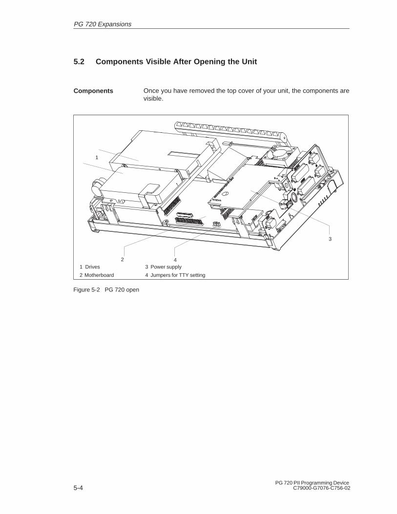
5-4PG 720 PII Programming Device
C79000-G7076-C756-02
5.2 Components Visible After Opening the Unit
Once you have removed the top cover of your unit, the components arevisible.
1
2
3
1 Drives
2 Motherboard
3 Power supply
4 Jumpers for TTY setting
4
Figure 5-2 PG 720 open
Components
PG 720 Expansions

5-5PG 720 PII Programming DeviceC79000-G7076-C756-02
5.3 Block Diagram of the Motherboard
3.3/
5 V
P
CI –
BU
S A
D(0
..31)
, C
TR
L(26
) (
33
MH
z B
us C
lock
)
29F
040
BIO
S51
2Kby
tes
ISA
BU
S
1
6bit
Dat
a,
24bi
t Add
ress
es
VG
A C
ontr
olle
rP
3V
Pow
er–
Sup
ply
Soft On/Off(SUSC_N)
P3V
(+
3.3v
olts
)
P5V
(+
5vol
ts)
’AB
T24
5
32 P
LCC
Aud
io
PIIX
4ES
yste
m C
ontr
olle
r
Sec
onda
ry
CD
RO
M
BG
A 32
4
32K
Hz
48M
Hz
LS 1
20 D
rive
Sou
nd
100
PQ
FP
AC
PI
Des
chut
es M
obile
Mod
ule
(MM
C–2
) with
Vol
tage
Reg
ulat
or, L
2 C
ache
and
440
BX
400
PIN
BG
A S
ocke
t
MD(0.63)
64
33
33MHz
2H
CLK
PC
LK
14.3
18 M
Hz
10
0/66
MH
z (
HO
ST
/BX
)[4
]
33M
Hz
( P
CI
)[8]
48M
Hz
( U
SB
) [
2]
14,3
18M
Hz
[3]
Clo
ck S
ynth
esiz
er C
DC
9318
48T
SS
OP
BX
PW
RO
K
SID
EB
AN
D S
igna
ls11
V_D
C
(+ 9
..20V
, O
verc
urre
nt–p
rote
cted
)
P12
V (
12v
olts
)
GT
L B
us
VR
M44
0BX
2
V_CPUIO
Bat
tery
with
Fue
lG
auge
2.5
/ 3.
3V51
2K L
2 C
ache
1.8
/ 3.3
V
492
BG
A
RA
S/C
SA
2/
3
Ban
k 3/
4
CK
E 2
/3
RA
S/C
SA
0/
1
Ban
k 1/
2
ED
O /
SD
RA
M
P3V
CK
E 0
/1
26
CTRL
32 AD(0:31)
CTRL
AD(0:31)
2632
( 3.3V Switched)
Sw
itch
Logi
cfo
r P
OW
ER
Pla
nes
ON
/OF
F
+5V
+3.
3V
2
V_D
C
V_5
V_3
V_3
S
VC
CA
GP
4
Module ID
VR_PWRGD
2
SM
BU
S
8 8
SD
(0:7
)
XD
(0:7
)
P3V
ED
O /
SD
RA
M
800x
600
LCD
TF
T
SV
GA
Dis
play
12.
1”
20p
LVDS
SA
(0:2
3)S
D(0
:15)
DR
EQ
(0:7
)D
AC
K(0
:7)
IRQ
(1:1
5)
2
Pag
e S
elec
t f
or 4
128K
Pag
es2
70
Prim
ary
ATA
–33
Har
d D
isk
US
B P
ort
MA
0..1
3R
AS
/CS
A 0
..3C
AS
/DQ
MA
0..7
SR
AS
,SC
AS
,CK
E0.
.3,W
E
Therm# PIIX4E
C&
T B
6900
02M
B S
GR
AM
Int
egra
ted
CTRL
26
Ext
. X
GA
1280
x102
4x25
6
P12
Vs
Spe
aker
int
.
Am
plifi
er
LM48
63M
Spe
aker
/Hea
dpho
ne
Spe
aker
CK
BF
28 T
SS
OP
22
ES
S S
OLO
1 (
AC
PI
)
P3V
s/P
1V5 CT
RL
5
DS90C363
Pow
er B
utto
n
3 / 3
.6V
VC
PU
IO
CT
RL
26A
D(0
:31)
32
M
ic.
(Ste
reo)
CD
C31
9
PC
98
+3V
Aux
SUSCB_N ( VR_ON )
+3V Aux
( 12
V S
wch
d. )
P3V
s
14.3
18 M
Hz
33M
Hz
Load_H
BATUSE_NBTLOAD_N
2
66M
Hz
AG
P 1
x
2
Por
t80
Test
Ada
pter
+5V
V_D
C
Mem
ory
Car
dS
IMA
TIC
S5
Mod
ule
SK
AN
SIM
AT
IC S
5/S
7
VC
C/V
PP
Mod
ule
10M
Hz
100
PQ
FP
20M
Hz :2
SA
(0:4
),C
TR
L (4
)
DB
(0:7
)
’AB
T24
5
2
1
S5
Chi
p S
elec
t
Ser
ial I
nter
face
TT
Y/A
G
CO
M1
MA
X 2
11E
TT
L
TT
Y
1
MA
X16
17
22
2
SM
BU
S
MU
X
2
2
5
Flo
ppy
33MHzFreerunning
BTLOW_NBTDOWN_N
P3V
s
SM
BU
S (
PIIX
4E)
ÎÎ
ÎÎÎ
ÎÎÎÎÎÎÎ K
eybo
ard
/ Tra
ckba
llP
S/2
Mou
se
MU
X’406
6
33M
Hz
Ultr
a IO
( A
CP
I 1.
0,P
C98
)
3 / 3
.6V
SA
(0:1
5),S
D(0
:7),
DR
Q(0
:3),
DA
CK
(0:3
)38
7C
TR
L
P5V
s
32kH
z
FD
C37
B78
7 (w
ith
RT
C)
128P
QF
P
14.3
18M
Hz
Cntl.
AD ( 0..31)
2632
RS
485
L2 D
P12
MB
/s
AS
PC
/2
PC
I905
0
Max
. 12
8k M
emor
y
33M
Hz
48M
Hz
100
PQ
FP
160
PQ
FP
RS
485
Hyb
ridP
5V_M
PI
Cntl.
AD ( 0..31)
2632
BU
S S
witc
hes
with
Lev
elsh
ifter
CT
RL(
3)
Port80 Chip Select
VC
C/
VP
P
Cntl.
Slo
t2Ty
pe I
/II/II
IS
lot1
Type
I/II
PC
Car
dP
C C
ard
6060
A(0
:25)
D(0
:15)
CT
RL(
18)
AD ( 0..31)
2632
Car
d B
us (
AC
PI
1.0
)
PC
I 122
5
P
C98
P3V
272B
GA
SUSCB_N ( VR_ON )
( 3.
3V S
wch
d. )
P5V
s ( 5V
Sw
chd.
)
208P
QF
P
P5V
s
P5V
s
P5V
s
P5V
_MP
I
P5V
_MP
I
33M
Hz
G_AD(0:31)
32
ES
1946
S
Prin
ter
Cen
tron
ics
(Flo
ppy)
LPT
1
RC
Net
.P
rote
ctio
n
EP
P/E
CP
266
/ 30
0 /
333
MH
zD
esch
utes
2.5V
I/O
1.7V
Cor
e
e.g.
Mod
em
CO
M2
MA
X 2
11E
Figure 5-3 Block Diagram, PG 720PII
PG 720 Expansions

5-6PG 720 PII Programming Device
C79000-G7076-C756-02
The motherboard is the heart of the PG 720. Here, data are processedand stored, and interfaces and device I/Os controlled and managed.
1
2
3
4
23
7/8
10/14
13
15
32
17
18
19 2021 9
5
11 1222
6
24
2625 16 27
33 3428 3029 31
Figure 5-4 Motherboard
The following components are located on the motherboard of thePG 720:
Table 5-1 Components of the MotherboardSerial
NumberFunctions
1 PC card slots
2 S5 submodule port3 Memory-card port4 Clock-battery connector
5 Pentium II CPU on base with cooling unit6 System memory, 2 slots7 External VGA port
8 COM 2 serial port9 TTY jumpers (X30)
10 COM 1/TTY serial port11 TTY receiver12 TTY transmitter
13 MPI/DP port14 LPT 1 parallel port15 PS/2 mouse port (external)
16 Connector for display17 Type A USB connector18 Port for keyboard and trackball
19 Floppy disk drive connection20 Power supply connection (from DC converter)
21 IDE for hard disk drive22 IDE for CD-ROM drive23 IDE for LS 120 drive
24 CD-ROM sound connection25 Connector for CPU fan
Motherboard
Components onthe Motherboard
PG 720 Expansions

5-7PG 720 PII Programming DeviceC79000-G7076-C756-02
Table 5-1 Components of the Motherboard
SerialNumber
Functions
26 Connector for On/Off switch
27 Connector for display unit28 Connector, reserved (microphone)
29 Jumper not installed
30 Connector, reserved (earphones)
31 Connector for speaker, left
32 Connector for speaker, right
33 Programming submodule
34 RS 485 hybrid
5.4 Switch Settings / Jumpers
X30 Function
2-3 4-5 Active TTY port (standard setting)
x off TTY send loop separate from power source(passive setting)
off x TTY receive loop separate from power source (pas-sive setting)
TTY Jumpers(x30) (see alsoFigure 5-2)
PG 720 Expansions

5-8PG 720 PII Programming Device
C79000-G7076-C756-02
5.5 Installing Memory Expansion Submodules
The motherboard has 2 slots for 144 pin SO DIMM memory submodules.This allows you to expand the memory capacity of your PG 720 to amaximum of 256 Mbytes.
The basic configuration consists of a 64 Mbyte SDRAM module. Onlyone module has to be installed.
Table 5-2 Slots for Memory Expansion
Memory Modules
32 Mbytes 64 Mbytes 128 Mbytes
64 Mbytes – 1 –
128 Mbytes – 2 –
128 Mbytes – – 1
192 Mbytes – 1 1
256 Mbytes – – 2
The order numbers for the SO DIMM memory submodules are listed inthe Operating Instructions.
Bank 0 Bank 1
Figure 5-5 Positions of the SO DIMM Memory Submodules
Standard Memory
PG 720 Expansions
5-9PG 720 PII Programming DeviceC79000-G7076-C756-02
!Caution
Risk of damage!
The electronic components of the printed circuit boards are extremelysensitive to electrostatic discharge. Certain precautionary measuresare therefore necessary when handling such components. Thesemeasures are explained in the guidelines for handlingelectrostatically-sensitive devices at the end of this manual.
To plug in expansion submodules, proceed as follows:
1. Open the unit as described in Section 5.1.
2. Plug the cards into the slots. Note the safety recess on theconnector side of the SO DIMM card.
3. Push the card down applying light pressure until it locks into place.
4. Close the unit (see Section 5.8).
!Caution
Risk of damage!
Make sure that the cards sit securely in the slots, otherwise they canfall out and be damaged.
The memory configuration is detected automatically. When you switchon the unit, the distribution of base and extended memory is displayedon the screen.
5.6 Processor Upgrade
You can boost the performance of your PG 720PII by installing otherPentium II processors. Consult your local service partner or distributor.
Note
Processor upgrade
If an upgrade is implemented, for example to a processor with adifferent frequency, it may be important to also upgrade the BIOS.
Installing the SODIMM Cards
Installation
PG 720 Expansions

5-10PG 720 PII Programming Device
C79000-G7076-C756-02
5.7 Replacing the Backup Battery
A backup battery (3.6 V lithium battery) powers the real-time clockeven after the PG 720 is switched off. In addition to the time of day, allthe information about the PG 720 (device configuration) is stored inRAM. If the backup battery fails or is removed, all these data are lost.
The clock uses very little power and the lithium battery has a highcapacity so that the battery can provide backup power for the real-timeclock for many years and seldom needs to be replaced.
If the battery voltage is too low, the time of day and the deviceconfiguration data in the RAM are lost.
In this case, you must replace the backup battery. The battery islocated on the drive mounting.
To change the battery, proceed as follows:
1. Switch off your PG 720 and remove the power cable and all theconnecting cables.
2. Open the unit as described in Section 5.1.
3. Now change the battery by removing the connector and releasing itfrom the clip.
4. Push the new battery firmly into the clip.
5. Close the unit as described in Section 5.7
Hard disk drive
Backup batteryClip
Figure 5-6 Clip for Backup Battery
!Caution
Risk of damage!
Only replace the lithium battery with an identical battery or with a typerecommended by the manufacturer (Order No.: W79084-E1003-B1).
Dispose of used batteries in keeping with local regulations.
If you change the battery or unplug the battery connector you must runthe SETUP program to reset your programming device’s configurationdata (see Chapter 6).
Battery PowerSupply forReal-Time Clockand Configuration
Battery Voltage too Low
Replacing theBattery
Changing SETUP
PG 720 Expansions
5-11PG 720 PII Programming DeviceC79000-G7076-C756-02
5.8 Closing the Unit
To close the unit, proceed as follows:
1. Tilt the unit to the horizontal position.
2. Place the front section on the casing.
3. Insert the CD-ROM ribbon cable and the CD-ROM audio line intothe drive connector on the backplane.
4. Press the front section onto the lower edge of the casing until thecatches in the base engage.
5. Insert the battery into the battery compartment and connect it up.
6. Close the battery cover.
7. Connect the keyboard connector to the back of the unit. Make surethat the cable is inserted in its channel.
8. Insert the keyboard cable in the cable conduit at the base of the de-vice.
9. Allow the keyboard hinge to slide into the receptacles in the base ofthe device.
10.Tilt the unit back into the operating position.
Your PG 720 is now ready for operation again.
Closing the Unit
PG 720 Expansions

5-12PG 720 PII Programming Device
C79000-G7076-C756-02
PG 720 Expansions

6-1PG 720 PII Programming DeviceC79000-G7076-C756-02
Configuring the PG 720
In this chapter, you will learn how to configure your programmingdevice. You need to do this if you change your system by adding,removing, or exchanging expansion modules and memory expansions,or by replacing a system module.
Section Contents Page
6.1 Changing the Device Configuration with SETUP 6-2
6.1.1 The Main Menu 6-5
6.1.2 The Advanced Menu 6-14
6.1.3 The Security Menu 6-19
6.1.4 The Power Savings Menu 6-21
6.1.5 The Boot Sequence Menu 6-23
6.1.6 The Version Menu 6-25
6.1.7 The Exit Menu 6-26
6.2 Configuring the PCMCIA Interface 6-30
What Does ThisChapter Contain?
ChapterOverview
6
6-2PG 720 PII Programming Device
C79000-G7076-C756-02
6.1 Changing the Device Configuration with SETUP
Your PG 720 device configuration is set for working with the softwaresupplied with the unit. You should only change the preset values if youhave modified your PG 720 in any way or if a fault occurs when the unitis powered up.
The SETUP program is in the ROM-BIOS. Information about thesystem configuration is stored in the battery-backed RAM of thePG 720.
You can use SETUP to set the hardware configuration (for example,hard disk type) and define the system characteristics. You can also useSETUP to set the time of day and date.
If incorrect SETUP data are detected when you boot the system, theBIOS prompts you to:
� Start SETUP by pressing F2 or
� Continue booting by pressing F1.
On completion of the startup test, the BIOS gives you the opportunityof starting the SETUP program by displaying the following screenprompt:
PRESS <F2> to enter SETUP
To start SETUP, proceed as follows:
1. Reset your PG 720 (warm or cold restart).
2. Press the F2 key as long as the BIOS prompt appears on thescreen.
The various menus and submenus are listed on the following pages.You can get all the information you need for the SETUP entry selectedfrom the “Item Specific Help” part of the relevant menu.
Changing theDeviceConfiguration
SETUPProgram
Incorrect SETUPData
Starting SETUP
SETUP Menus
Configuring the PG 720
6-3PG 720 PII Programming DeviceC79000-G7076-C756-02
With the standard setting of your programming device, the displayshown below appears following power-on:
Phoenix NoteBIOS 6.0 A5E000xxxxx-01
Copyright 1985-98 Phoenix Technologies Ltd., All Rights
Reserved.
SIEMENS PG 720PII
CPU = Pentium II 266MHz
640K System RAM Passed
63MB Extended RAM Passed
0512K Cache SRAM passedSystem BIOS shadowed
Video BIOS shadowed
UMB upper limit segment address: xxxx
Mouse initialized
Fixed Disk 0: IBM DADA 26480ATAPI CD–ROM: T...
Press <F2> to enter SETUP
If you press the F2 key while the above display is shown, you selectthe ROM-based BIOS setup program. In this program, you can set anumber of system functions and hardware configurations of yourprogramming device.
The standard settings are effective on delivery. You can change thesesettings using the BIOS setup. The modified settings become effectivewhen you have saved them and terminated the BIOS setup.
Screen DisplayFollowingPower On
Configuring the PG 720

6-4PG 720 PII Programming Device
C79000-G7076-C756-02
The following screen form appears when you start the BIOS setup:
Menu bar
Operating keys
Selectablesubmenu
Help window
PhoenixBIOS Setup Utility
Item Specific HelpSystem Time:
ESC Exit
TabSystem Date:
[ 15:35:32 ]
Select Item
Select Menu
+ / –
Enter Select
Change Values
Sub-Menu
F9
F10
Setup Defaults
Save and Exit
Shift-Tab Enter, orselects field.Diskette A: [ 1.44 MB, 31/2” ]
Primary Master [6495MB]Primary Slave [None]
Memory Cache:Boot OptionsKeyboard Features
[Write Back]
Hardware Options
System Memory:Extended Memory:
Main Security Power ExitAdvanced
Secondary Master [CD-ROM]Secondary Slave [None]
[ 01/23/1999 ]
640 KB64512 KB
Example:Hour/Minute/SecondMonth/Day/Year
Boot Sequence Version
Header
F1 Help
Battery Capacity: 100%
Figure 6-1 Main SETUP Menu
The screen is divided into four sections. In the top section, you canselect the menu screens [Main], [Advanced], [Security], [Power], [BootSequence], [Version], [Exit]. In the left of the center section you canselect various settings or submenus. Brief help texts appear on theright for the currently selected menu entry. The bottom section containsinformation for operator inputs.
You can move between the menu screens using the cursor keys [←]and [→].
Menu Meaning
Main System functions are set here
Advanced An extended system configuration can be set here
Security Security functions are set here, for example a password
Power Power functions can be selected here
Boot Sequence The boot priorities are defined here
Version Information about the programming device’s release status
Exit Used for terminating and saving
Menu Structure
Configuring the PG 720
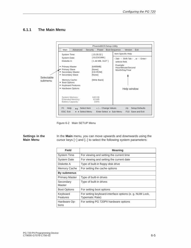
6-5PG 720 PII Programming DeviceC79000-G7076-C756-02
6.1.1 The Main Menu
Selectablesubmenu
PhoenixBIOS Setup-Utility
Item Specific HelpSystem Time:
ESC
TabSystem Date:
[ 15:35:32 ]
Select Item
Select Menu
+ / –
Enter Select
Change Values
Sub-Menu
F9
F10
Setup Defaults
Save and Exit
Shift-Tab Enter, or,
selects field.Diskette A: [ 1.44 MB, 31/2” ]
Primary Master [6495MB]Primary Slave [None]
Memory Cache:Boot OptionsKeyboard Features
[Write Back]
Hardware Options
System Memory:Extended Memory:
Main Security PowerAdvanced
Secondary Master [CD-ROM]Secondary Slave [None]
[ 01/23/1999 ]
640 KB
Example:Hour/Minute/SecondMonth/Day/Year
ExitBoot Sequence Version
63 MB
Help window
F1 Help
Exit
Battery Capacity: 100%
Figure 6-2 Main SETUP Menu
In the Main menu, you can move upwards and downwards using thecursor keys [↑ ] and [↓ ] to select the following system parameters:
Field Meaning
System Time For viewing and setting the current time
System Date For viewing and setting the current date
Diskette A Type of built-in floppy disk drive
Memory Cache For setting the cache options
By submenus
Primary Master Type of built-in drives
SecondaryMaster
Type of built-in drives
Boot Options For setting boot options
KeyboardFeatures
For setting keyboard-interface options (e. g. NUM Lock,Typematic Rate)
Hardware Op-tions
For setting PG 720PII hardware options
Settings in theMain Menu
Configuring the PG 720
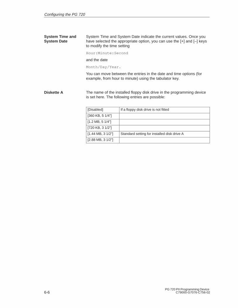
6-6PG 720 PII Programming Device
C79000-G7076-C756-02
System Time and System Date indicate the current values. Once youhave selected the appropriate option, you can use the [+] and [–] keysto modify the time setting
Hour:Minute:Second
and the date
Month/Day/Year.
You can move between the entries in the date and time options (forexample, from hour to minute) using the tabulator key.
The name of the installed floppy disk drive in the programming deviceis set here. The following entries are possible:
[Disabled] If a floppy disk drive is not fitted
[360 KB, 5 1/4”]
[1.2 MB, 5 1/4”]
[720 KB, 3 1/2”]
[1.44 MB, 3 1/2”] Standard setting for installed disk drive A
[2.88 MB, 3 1/2”]
System Time andSystem Date
Diskette A
Configuring the PG 720
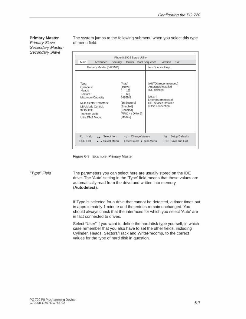
6-7PG 720 PII Programming DeviceC79000-G7076-C756-02
The system jumps to the following submenu when you select this typeof menu field:
PhoenixBIOS Setup Utility
Item Specific Help
ESC Exit
Select Item
Select Menu
+ / –
Enter Select
Change Values F9
F10
Setup Defaults
Save and ExitSub-Menu
Type:Cylinders:
[Auto]
Heads:SectorsMaximum Capacity
Main Security PowerAdvanced
Primary Master [6495MB]
Multi-Sector Transfers:LBA Mode Control:32 Bit I/O:Transfer Mode:
[13424][ 15][ 63]6495MB
[16 Sectors][Enabled][Enabled][FPIO 4 / DMA 2]
Ultra DMA Mode: [Mode2]
[AUTO] (recommended)Autotypes installed IDE-devices
[USER]Enter parameters of IDE-devices installed at this connection
ExitBoot Sequence Version
F1 Help
Figure 6-3 Example: Primary Master
The parameters you can select here are usually stored on the IDEdrive. The ’Auto’ setting in the ’Type’ field means that these values areautomatically read from the drive and written into memory (Autodetect ).
If Type is selected for a drive that cannot be detected, a timer times outin approximately 1 minute and the entries remain unchanged. Youshould always check that the interfaces for which you select ’Auto’ arein fact connected to drives.
Select “User” if you want to define the hard-disk type yourself, in whichcase remember that you also have to set the other fields, includingCylinder, Heads, Sectors/Track and WritePrecomp, to the correctvalues for the type of hard disk in question.
Primary MasterPrimary SlaveSecondary Master-Secondary Slave
”Type” Field
Configuring the PG 720

6-8PG 720 PII Programming Device
C79000-G7076-C756-02
The entry in the Multi-Sector Transfer field defines the number ofsectors transferred per interrupt. The value depends on the drive andshould be set only by setting the Type field to Auto.
Disabled
2,4,8,16 sectors
If the LBA Mode Control field (enabled,disabled) is set to ’Enabled’, thesystem supports hard disks with capacities greater than 528 Mbytes.The value depends on the drive and should be set only by setting theType field to Auto.
The setting in the 32 Bit I/O field defines the mode of access for thedrive
Disabled 16-bit access
Enabled 32-bit access (default)
The settings in these fields define the interface’s data-transfer rate. Thevalue depends on the drive and should be set only by setting the Typefield to Auto.
Hit ESC to exit the submenu.
”Multi-Sector Trans-fer” Field
”LBA Mode Control”field
”32 Bit I/O” Field
”Transfer Mode” and”Ultra DMA Mode”Fields
Configuring the PG 720
6-9PG 720 PII Programming DeviceC79000-G7076-C756-02
The following pop-up menu appears when you select the option“Memory cache” in the main menu:
PhoenixBIOS Setup Utility
Item Specific HelpSystem Time:
ESC Exit
System Date:
[ 15:35:32 ]
Select Item
Select Menu
+ / –
Enter Select
Change Values
Sub-Menu
F9
F10
Setup Defaults
Save and Exit
Diskette A: [ 1.44 MB, 31/2” ]
Primary Master [6495MB]Primary Slave [None]
Memory Cache:Boot OptionsKeyboard Features
[Write
Hardware Options
System Memory:Extended Memory:
Main Security PowerAdvanced
Secondary Master [CD-ROM]Secondary Slave [None]
[ 01/23/1998 ]
640 KB63 MB
Controls caching of systemconventional memory andmemory above one megabyte
DisabledWrrite ThroughWrrite Back
ExitBoot Sequence Version
F1 Help
Battery Capacity: 100%
Figure 6-4 “Memory Cache” Menu
A cache is a fast memory buffer between the CPU and main memory(DRAM). Recurrent memory access operations are executed in the fastcache, instead of main memory, if the function is enabled. In rareinstances involving some hardware and software combinations, it maybe necessary to disable the cache because the program runtimes orwaits are too short on account of the fast cache.
Field Meaning
[Disabled] Cache is disabled
[Write Through] Write access is not concluded until the entry has beenmade in main memory
[Write Back] Write access is concluded immediately, the entry in mainmemory takes place in the background (default)
“Memory Cache”Field
Configuring the PG 720

6-10PG 720 PII Programming Device
C79000-G7076-C756-02
The following submenu appears when you select the option “BootOptions” in the main menu:
PhoenixBIOS Setup-Utility
Item Specific Help
ESC Exit
Select Item
Select Menu
+ / –
Enter Select
Change Values F9
F10
Setup Defaults
Save and ExitSub-Menu
QuickBoot Mode:
SETUP prompt: [Enabled]
Main Security PowerAdvanced
Boot Options
[Enabled] Allows the system to skip certaintests while booting. This willdecrease the time needed to bootthe system.
POST Errors: [Enabled]
Floppy check: [Disabled]
Summary screen: [Enabled]
ExitBoot Sequence Version
F1 Help
Figure 6-5 ”Boot Options” Submenu
Quick BootMode
Some hardware tests are skipped to speed up the bootprocedure.
SETUP prompt The message PRESS <F2> to enter Setup appears at thebottom of the screen during the system run-up phase.
POST Errors The boot process is stopped if an error is detected; youmust press F1 to acknowledge. Enter “Disabled”to avoid thenecessity of acknowledging errors, for example if nokeyboard is connected.
Floppy check The floppy head is stepped inward and then back to itsoriginal position during the system run-up phase. This testis useful because it reinitializes the drive.
Summaryscreen
The most important system parameters are displayed whenthe system run-up phase completes.
’Enabled’ means that the feature is active. ’Disabled’ means that thefeature is inactive.
Option “ BootOptions”
Configuring the PG 720

6-11PG 720 PII Programming DeviceC79000-G7076-C756-02
Example of a summary screen:
PhoenixBIOS Set Up Utility
CPU:CPU Speed 266 MHz
System 640 KBExtended 63 MBShadow RAM: 384 KBCache RAM: 512 KB
Hard Disk 0: 6495 MBHard Disk 1: None
System ROM:BIOS Date: 03/06/97
Fxx – FFFF
COM Ports: 03F8, 02F8LPT Ports: 0378Display Type: VGAPS/2 Mouse: Installed
Diskette A: 1,44 MB, 31/2 ”
SIMATIC PG PG720 PII BIOS Version: V7....
Pentium PII
Hard Disk 2: CD-ROMHard Disk 3: None
Battery capacity: 95%
Figure 6-6 Summary Screen
The Summary screen appears when the system run-up phasecompletes.
The following submenu appears if you select the “Keyboard Features”field in the main menu:
PhoenixBIOS Setup Utility
Item Specific Help
ESC Exit
Select Item
Select Menu
+ / –
Enter Select
Change Values F9
F10
Setup Defaults
Save and ExitSub-Menu
Numlock:
Key Click: [Disabled]
Main Security PowerAdvanced
Keyboard Features
[On] Selects Power-on state forNumlock
Keyboard auto-repeat rate: [30/sec]
Keyboard auto-repeat delay: [1/2 sec]
ExitBoot Sequence Version
F1 Help
Figure 6-7 ”Keyboard Features” Submenu
Numlock Switches Numlock on or off following power on
Key Click A keystroke can be heard
Keyboard auto-repeat rate Increase in automatic key repeat rate
Option “KeyboardFeatures”
Configuring the PG 720

6-12PG 720 PII Programming Device
C79000-G7076-C756-02
The following submenu appears when you select the “HardwareOptions” field in the main menu:
PhoenixBIOS Setup-Utility
Item Specific Help
ESC Exit
Select Item
Select Menu
+ / –
Enter Select
Change Values F9
F10
Setup Defaults
Save and ExitSub-Menu
PCI - MPI / DP:
Main Security PowerAdvanced
Hardware Options
[Enabled]Enable or disable the PluPCI - Multi Point Interface (MPI / DP)Programming interface: [Enabled]
Trackball / PS/2 Mouse:: [Internal]
CRT / LCD selection: [SIMULTAN]CRT 640 X 480: [75 Hz]CRT 800 X 600: [75 Hz]CRT 1024 X 768: [75 Hz]LCD-Screensize: [Graph& Text Expand]
Cardbus/PCMCIA Slot: [Enabled]
ExitBoot Sequence Version
F1 Help
Figure 6-8 ”PG 720 PII Hardware Options” Submenu
The parameters of the interfaces present on the basic module are sethere.
Entry Meaning
PCI-MPI/DP Enables the CP5611-compatible MPI/DP interface. Therecourses are managed by the BIOS PCI plug & playmechanism.
Cardbus /PCMCIA Slot
[Disabled] Disables the Cardbus / PCMCIAinterfaces.
[Enabled] The resources are managed by the BIOSPCI plug & play mechanism.
Programminginterface
Enables or disables the interface for SIMATIC S5 memorymodules and SIMATIC memory cards. This interface usesthe I/O address range 300h-31fh.
CRT / LCDselection
[LCD Enabled] All data is output only to the internalLCD, the 15-way VGA port is disabled
[CRT Enabled] For maximum resolution the display signals are output only to the 15-wayVGA port; the LCD interface of the VGAcontroller is disabled.
[SIMULTAN] Both display interfaces are enabled and operate simultaneously. Note, however, that the LCD does notsupport all resolutions.
CRT 640 x 480 Refresh rate with a resolution of 640x480 pixels
CRT 800 x 600 Refresh rate with a resolution of 800x600 pixels
“HardwareOptions” Field
Configuring the PG 720
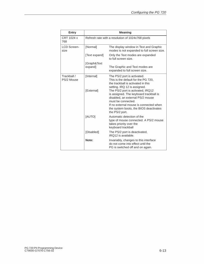
6-13PG 720 PII Programming DeviceC79000-G7076-C756-02
Entry Meaning
CRT 1024 x768
Refresh rate with a resolution of 1024x768 pixels
LCD Screen-size
[Normal] The display window in Text and Graphicmodes is not expanded to full screen size.
[Text expand] Only the Text modes are expanded to full screen size.
[Graph&Text expand] The Graphic and Text modes are
expanded to full screen size.
Trackball / PS/2 Mouse
[Internal] The PS/2 port is activated. This is the default for the PG 720, the trackball is activated in thissetting. IRQ 12 is assigned.
[External] The PS/2 port is activated, IRQ12 is assigned. The keyboard trackball is disabled, an external PS/2 mousemust be connected. If no external mouse is connected whenthe system boots, the BIOS deactivatesthe PS/2 port.
[AUTO] Automatic detection of thetype of mouse connected. A PS/2 mousetakes priority over the keyboard trackball
[Disabled] The PS/2 port is deactivated,IRQ12 is available.
Note: Invariably, changes to this interface do not come into effect until thePG is switched off and on again.
Configuring the PG 720

6-14PG 720 PII Programming Device
C79000-G7076-C756-02
6.1.2 The Advanced Menu
PhoenixBIOS Setup-Utility
Item Specific Help
ESC Exit
Select Item
Select Menu
+ / –
Enter Select
Change Values F9
F10
Setup Defaults
Save and ExitSub-Menu
Main Security Power
Installed O/S: [Other]
Reset Configuration Data: [No]
Local Bus IDE adapter:
Floppy disk controller: [Enabled]
[Primary & Secondary]
Large Disk Access Mode: [DOS]
Memory Gap at 15 Mbyte: [Disabled]
COM / LPT Configuration
Menu Structure
PCI Configuration
Harddisk Pre-Delay: [Disabled]
ExitBoot Sequence Version
Set up Warning.Setting titems on this menu to incorrect valuesmay cause yuor system to malfunction. Peripherial Configuration
F1 Help
Advanced
Figure 6-9 ”Advanced” Menu
Installed O/S Plug & play means that all modules are automaticallydetected and installed, providing they support thePlug&Play functionality.
[other] BIOS handles the entire Plug&Play capability, default configuration
[Win98] The operating system handles some of thePlug&Play functions
Reset Configu-ration Data
[Yes] All installations under Plug&Play are deleted andreconfiguration is triggered the next time the system boots. The entry is then reset to[No]. System components that do not supportPlug&Play have to be entered manually.
Diskette con-troller
Enables or disables the floppy-disk controller on themotherboard.
Local Bus IDEadapter
[Primary] One IDE interface for max. two [Secondary] drives.[Primary & Secondary] Two IDE interfaces for max. four
drives.
[Disabled] No local IDE interface.
Large Disk Ac-cess Mode
[DOS] The drive tables are adapted for DOS accessoperations in accordance with Enhanced IDE.
[OTHER] The tables are not adapted.
Settings in theAdvanced Menu
Configuring the PG 720

6-15PG 720 PII Programming DeviceC79000-G7076-C756-02
Harddisk Pre-Delay
[Disabled] No additional start-up delay for the hard disk.
3 to 30 Additional start-up delay for the seconds hard disk; needed only for older-generation
hard disks.
Memory Gap at15 MByte
[Disabled] The area from 15 to 16 Mbytes is not availableas PC-Card memory.
[Enabled] The area from 15 to 16 Mbytes is enabled for PC-Cards which can use this addressrange.
PhoenixBIOS Setup Utility
Item Specific Help
ESC Exit
Select Item
Select Menu
+ / –
Enter Select
Change Values F9
F10
Setup Defaults
Save and ExitSub-Menu
Main Security Power
Base I/O address:[Enabled]
Interrupt: [IRQ 4]
Internal COM 1:
COM / LPT Configuration
Configure internal COM port usingoptions:[Disabled]
No configuration[Enabled]
User configuration
[Auto]BIOS or OS choosesconfiguration
[OS Controlled]Controlled by OS
Base I/O address:[Enabled]
Interrupt: [IRQ 3]
Internal COM2:
Mode:[Enabled]
Base I/O address: [378]
Internal LPT1:
Interrupt: [IRQ 7]
[Output only]
[2F8]
[3F8]
SubmenuCOM/LPT Configuration ExitBoot Sequence Version
F1 Help
Advanced
Figure 6-10 “COM / LPT Configuration” Submenu
The resources used by an interface are released when you disable theinterface in question.
The I/O addresses and interrupts are preassigned: it is advisable not tochange these default assignments.
Mode: Use this setting to set the operating mode of the printerinterface. Make sure that the setting matches the printerconnected to the printer port. See the printer documentationfor details of the appropriate settings.
Printer Port Internal LPT1
Configuring the PG 720

6-16PG 720 PII Programming Device
C79000-G7076-C756-02
PhoenixBIOS Setup Utility
Item Specific Help
ESC Exit
Select Item
Select Menu
+ / –
Enter Select
Change Values F9
F10
Setup Defaults
Save and ExitSub-Menu
Main Security Power
PCI Configuration
Reserve specific IRQs foruse by legacy ISA devices
PCI/PNP ISA Resource Exclusion
PCI IRQ line 1:PCI IRQ line 2:PCI IRQ line 3:PCI IRQ line 4:
[Auto Select][Auto Select][Auto Select][Auto Select]
PCI ConfigurationSubmenu
ExitBoot Sequence Version
F1 Help
Advanced
Figure 6-11 ”PCI Configuration” Submenu
Configuring the PG 720

6-17PG 720 PII Programming DeviceC79000-G7076-C756-02
Available means that the Plug&Play mechanism in BIOS can allocatethe IRQ to plug & play submodules or motherboard functions.
Use the ’Reserved’ setting only if the interrupt has to be assignedspecifically to PCMCIA submodules with no plug&play capability.
PhoenixBIOS Setup Utility.
Item Specific Help
ESC Exit
Select Item
Select Menu
+ / –
Enter Select
Change Values F9
F10
Setup Defaults
Save and ExitSub-Menu
Main Security Power
IRQ 3:IRQ 4:IRQ 5:IRQ 7:IRQ 9:IRQ 10:IRQ 11:
[Available][Available][Available][Available][Available][reserved][reserved]
PCI / PNP ISA IRQ Resource Exclusion
Reserves the specifiedIRQ for use by legacyISA devices
ExitBoot Sequence Version
F1 Help
Advanced
Figure 6-12 “PCI / PNP ISA IRQ Resource Exclusion” Submenu
Submenu PCI/PNPISA IRQ ResourceExclusion
Configuring the PG 720
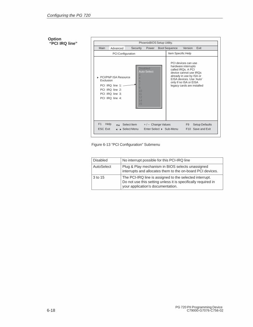
6-18PG 720 PII Programming Device
C79000-G7076-C756-02
PhoenixBIOS Setup Utility.
Item Specific Help
ESC Exit
Select Item
Select Menu
+ / –
Enter Select
Change Values F9
F10
Setup Defaults
Save and ExitSub-Menu
Main Security Power
PCI Configuration
PCI devices can usehardware interruptscalled IRQs. A PCIdevice cannot use IRQsalready in use by ISA orEISA devices. Use ’Auto’only if no ISA or EISAlegacy cards are installedPCI IRQ line 1:
PCI IRQ line 2:PCI IRQ line 3:
PCI IRQ line 4:
PCI/PNP ISA ResourceExclusion
DisabledAuto Select345791011121415
Option “PCI IRQ line”
ExitBoot Sequence Version
F1 Help
Advanced
Figure 6-13 “PCI Configuration” Submenu
Disabled No interrupt possible for this PCI-IRQ line
AutoSelect Plug & Play mechanism in BIOS selects unassignedinterrupts and allocates them to the on-board PCI devices.
3 to 15 The PCI-IRQ line is assigned to the selected interrupt.Do not use this setting unless it is specifically required inyour application’s documentation.
Configuring the PG 720
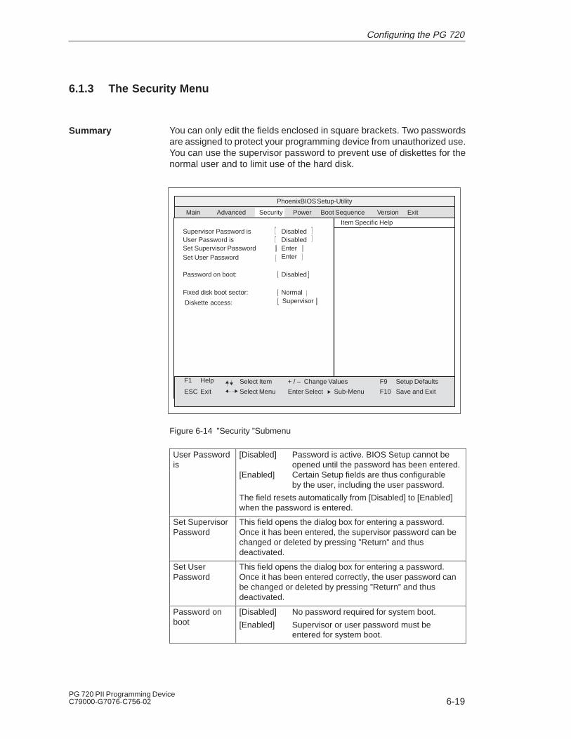
6-19PG 720 PII Programming DeviceC79000-G7076-C756-02
6.1.3 The Security Menu
You can only edit the fields enclosed in square brackets. Two passwordsare assigned to protect your programming device from unauthorized use.You can use the supervisor password to prevent use of diskettes for thenormal user and to limit use of the hard disk.
PhoenixBIOS Setup-Utility
Item Specific Help
ESC Exit
Select Item
Select Menu
+ / –
Enter Select
Change Values F9
F10
Setup Defaults
Save and ExitSub-Menu
Supervisor Password is DisabledUser Password is DisabledSet Supervisor PasswordSet User Password Enter
Enter
Password on boot: Disabled
Diskette access: SupervisorFixed disk boot sector: Normal
Main Security PowerAdvanced ExitBoot Sequence Version
F1 Help
Figure 6-14 ”Security ”Submenu
User Passwordis
[Disabled] Password is active. BIOS Setup cannot beopened until the password has been entered.
[Enabled] Certain Setup fields are thus configurableby the user, including the user password.
The field resets automatically from [Disabled] to [Enabled]when the password is entered.
Set SupervisorPassword
This field opens the dialog box for entering a password.Once it has been entered, the supervisor password can bechanged or deleted by pressing ”Return” and thusdeactivated.
Set UserPassword
This field opens the dialog box for entering a password.Once it has been entered correctly, the user password canbe changed or deleted by pressing ”Return” and thusdeactivated.
Password onboot
[Disabled] No password required for system boot.
[Enabled] Supervisor or user password must be entered for system boot.
Summary
Configuring the PG 720
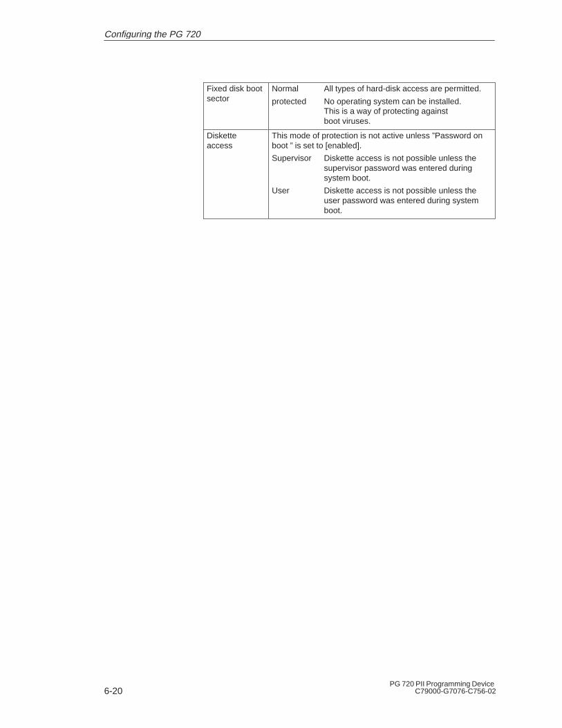
6-20PG 720 PII Programming Device
C79000-G7076-C756-02
Fixed disk bootsector
Normal All types of hard-disk access are permitted.
protected No operating system can be installed. This is a way of protecting against
boot viruses.
Disketteaccess
This mode of protection is not active unless ”Password onboot ” is set to [enabled].
Supervisor Diskette access is not possible unless the supervisor password was entered during system boot.
User Diskette access is not possible unless the user password was entered during system
boot.
Configuring the PG 720

6-21PG 720 PII Programming DeviceC79000-G7076-C756-02
6.1.4 The Power Menu
This menu has the following structure:
PhoenixBIOS Setup-Utility
Item Specific Help
ESC Exit
Select Item
Select Menu
+ / –
Enter Select
Change Values F9
F10
Setup Defaults
Save and Exit
APM (Advanced Power Management)allows APM aware software to manage power savings, if enabled
Sub-Menu
Power Savings: Disabled
Standby Timeout: OffSuspend Timeout: Off
Hard Disk Timeout: Disabled
Backlight [Full on]
Main
Security PowerAdvanced
APM: Enabled
DisabledCustomizedMaximum Power SavingsMaximum Performance
Suspend Mode: [Save to Disk]
Fan Control: [Enabled]
Battery Low Condition: [Save to Disk]
Resume On Modem Ring: [Off]Resume On Time: [Off]Resume Time: [00:00:00]
ExitBoot Sequence Version
F1 Help
Figure 6-15 “Power” Submenu
The Power menu offers a number of power-saver modes forenvironmentally friendly computing:
APM(AdvancedPower Manage-ment)
[Enabled] The operating system can shut down system resources when they are not needed.
[Disabled] The operating system is denied APM access.
Power Savings [Disabled] No power-saving functions[Customize, Maximum Power Savings, MaximumPerformance]
User-selectable and preset power-saving functions for maximum andminimum power saving. You can set the parameters forStandby/Suspend Timeouts and Fixed Disk Timeout or they set automatically to their defaults.
Standby Timeout
[Off] No standby mode[30 seconds or ...minutes after your PG enters1, 2, 4, 8, 12, 16] standby mode.
Suspend Timeout
[Off] No suspend mode[1,2, 5, 10, 15, seconds after your PG enters20, 30] suspend mode.
Summary
Configuring the PG 720

6-22PG 720 PII Programming Device
C79000-G7076-C756-02
Major components are shut down in suspend mode. The informationneeded for reactivating the programming device is buffered.
Suspend Mode [Save to Disk] In suspend mode all relevant data is written to a defined sector of thehard disk
[Save to DRAM] In suspend mode all relevant data is stored in main memory.
Hard Disk Timeout
[Disabled] The hard disk does not shut down.
[10, 15, 30, 60] Time since the last hard-disk access,the hard disk is shut down. The next time it is accessed, the hard disk starts spinning again after a brief delay.
Backlight [Full on] Display lighting is at full brightness[reduced] Brightness is reduced
Fan Control [Disabled] Fan always runs at full speed[Enabled] Fan speed depends on temperature.
Battery LowCondition
[Save to Disk] The Save to Disk mode is activated as soon as the battery charge level drops to minimum.
[Beeper] When the battery charge level drops to minimum the beeper sounds a warning
[Power Off] At this setting, the device is shut down when the charge level drops tominimum.
Resume onModem Ring
[Off] If this function is enabled, the programming
[On] device is reawakened from suspend mode by the modem’s ”Ring” signal.
Resume OnTime
[On] If this function is enabled the programming device is automaticallyswitched on at the preset time.
[Off] ’Off’ means this function is disabled.
Resume Time Time for automatic restart
Configuring the PG 720
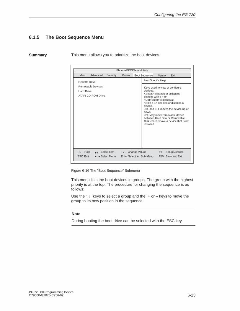
6-23PG 720 PII Programming DeviceC79000-G7076-C756-02
6.1.5 The Boot Sequence Menu
This menu allows you to prioritize the boot devices.
Boot Sequence
PhoenixBIOS Setup-Utility
Item Specific Help
ESC Exit
Select Item
Select Menu
+ / –
Enter Select
Change Values F9
F10
Setup Defaults
Save and Exit
Keys used to view or configuredevices:<Enter> expands or collapses devices with a + or –<Ctrl+Enter> expands all<Shift + 1> enables or disables adevice.<+> and <–> moves the device up ordown.<n> May move removable devicebetween Hard Disk or RemovableDisk <d> Remove a device that is notinstalled
Sub-Menu
Main
Security PowerAdvanced
Diskette Drive
Removable Devices
Hard Drive
ATAPI CD-ROM Drive
ExitVersion
F1 Help
Figure 6-16 The ”Boot Sequence” Submenu
This menu lists the boot devices in groups. The group with the highestpriority is at the top. The procedure for changing the sequence is asfollows:
Use the ↑↓ keys to select a group and the + or – keys to move thegroup to its new position in the sequence.
Note
During booting the boot drive can be selected with the ESC key.
Summary
Configuring the PG 720

6-24PG 720 PII Programming Device
C79000-G7076-C756-02
Groups marked + can contain more than one device. When you selecta group marked in this way, hit Enter to view the list of devices in thegroup. See the figure below for an illustration:
Boot Sequence
PhoenixBIOS Setup-Utility
Item Specific Help
ESC Exit
Select Item
Select Menu
+ / –
Enter Select
Change Values F9
F10
Setup Defaults
Save and Exit
Keys used to view or configure devices:<Enter> expands or collapses devices with a + or –<Ctrl+Enter> expands all<Shift + 1> enables or disables adevice.<+> and <–> moves the device up ordown.<n> May move removable devicebetween Hard Disk or RemovableDisk <d> Remove a device that is notinstalled
Sub-Menu
Main
Security PowerAdvanced
–Diskette Drive
Floppy Drive
–Removable Devices
Floppy Drive
–Hard Drive
IBM-DTCA-26480-(PM)
Alternate Device
ATAPI CD-ROM Drive
ExitVersion
F1 Help
Figure 6-17 The ”Boot Sequence” Submenu
This screen shows all possible boot devices; within a given group thehighest priority device is always listed first. Here again, you can changethe sequence as described above.
If a boot device is not available, the next device in the sequence isautomatically checked to ascertain whether or not it is bootable.
Configuring the PG 720
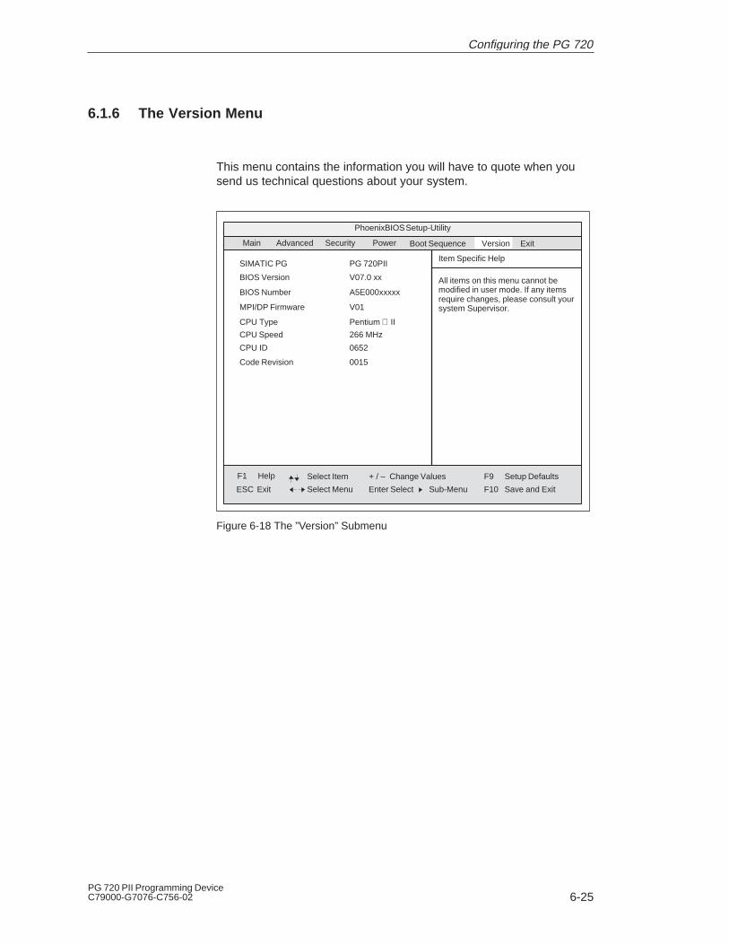
6-25PG 720 PII Programming DeviceC79000-G7076-C756-02
6.1.6 The Version Menu
This menu contains the information you will have to quote when yousend us technical questions about your system.
Boot Sequence
PhoenixBIOS Setup-Utility
Item Specific Help
ESC Exit
Select Item
Select Menu
+ / –
Enter Select
Change Values F9
F10
Setup Defaults
Save and Exit
All items on this menu cannot be modified in user mode. If any itemsrequire changes, please consult yoursystem Supervisor.
Sub-Menu
Main
Security PowerAdvanced
SIMATIC PG
ExitVersion
PG 720PII
BIOS Version V07.0 xx
BIOS Number A5E000xxxxx
MPI/DP Firmware V01
CPU Type Pentium II
CPU Speed 266 MHz
CPU ID 0652
Code Revision 0015
F1 Help
Figure 6-18 The ”Version” Submenu
Configuring the PG 720

6-26PG 720 PII Programming Device
C79000-G7076-C756-02
6.1.7 The Exit Menu
The setup program is always terminated using this menu.
PhoenixBIOS Setup-Utility
Item Specific Help
ESC Exit
Select Item
Select Menu
+ / –
Enter Select
Change Values F9
F10
Setup Defaults
Save and Exit
Exit after writing all changed SETUPitem values to CMOS.
Sub-Menu
Save Changes & ExitExit Without Saving ChangesGet Default ValuesLoad Previous ValuesSave Changes
Main
Security PowerAdvanced ExitBoot Sequence Version
F1 Help
Figure 6-19 ”Exit” Submenu
Save Changes& Exit
All changes are saved; a system restart is carried out withthe new parameters.
DiscardChanges & Exit
All changes are rejected; a system restart is carried out withthe old parameters.
Get DefaultValues
All parameters are set to safe values.
Load PreviousValues
The last saved values are reloaded.
Save Changes Save all Setup settings.
The Exit Menu
Configuring the PG 720

6-27PG 720 PII Programming DeviceC79000-G7076-C756-02
If you have made any modifications to your standard SETUP settings, youcan enter them in the following table. You can then refer to these entriesif you need to make any hardware modifications later.
Note
Print the following table out and keep the pages in a safe place onceyou have filled in your entries.
System Parameter Standard Settings Your EntriesMain
System Time
System Date
Diskette A 1,44 MB, 31/2
Primary Master C: 6495 MB
Primary Slave None
Secondary Master CD-ROM
Secondary Master None
Memory Cache Write back
Boot options
Quick Boot Mode Enabled
SETUP prompt Enabled
POST errors Enabled
Floppy check Disabled
Summary Screen Enabled
Keyboard Features
Numlock Off
Key click Disabled
Keyboard auto repeat time 30/s
Keyboard auto repeat delay 1/2s
Hardware Options
PCI-MPI/DP: Enabled
Cardbus/PCMCIA Slot Enabled
Programming Interface Enabled
CRT/LCD selection SIMULTAN
CRT 640 x 480 75
CRT 800 x 600 75
CRT 1024 x 768 75
LCD Screensize Graph&Text Expanded
Trackball / PS2 Mouse Internal
Advanced
Documenting YourDeviceConfiguration
Configuring the PG 720
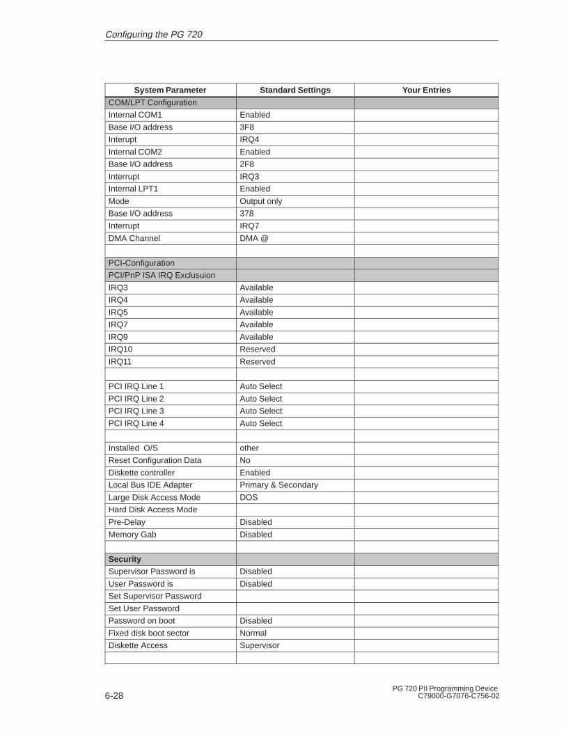
6-28PG 720 PII Programming Device
C79000-G7076-C756-02
System Parameter Your EntriesStandard Settings
COM/LPT Configuration
Internal COM1 Enabled
Base I/O address 3F8
Interupt IRQ4
Internal COM2 Enabled
Base I/O address 2F8
Interrupt IRQ3
Internal LPT1 Enabled
Mode Output only
Base I/O address 378
Interrupt IRQ7
DMA Channel DMA @
PCI-Configuration
PCI/PnP ISA IRQ Exclusuion
IRQ3 Available
IRQ4 Available
IRQ5 Available
IRQ7 Available
IRQ9 Available
IRQ10 Reserved
IRQ11 Reserved
PCI IRQ Line 1 Auto Select
PCI IRQ Line 2 Auto Select
PCI IRQ Line 3 Auto Select
PCI IRQ Line 4 Auto Select
Installed O/S other
Reset Configuration Data No
Diskette controller Enabled
Local Bus IDE Adapter Primary & Secondary
Large Disk Access Mode DOS
Hard Disk Access Mode
Pre-Delay Disabled
Memory Gab Disabled
SecuritySupervisor Password is Disabled
User Password is Disabled
Set Supervisor Password
Set User Password
Password on boot Disabled
Fixed disk boot sector Normal
Diskette Access Supervisor
Configuring the PG 720
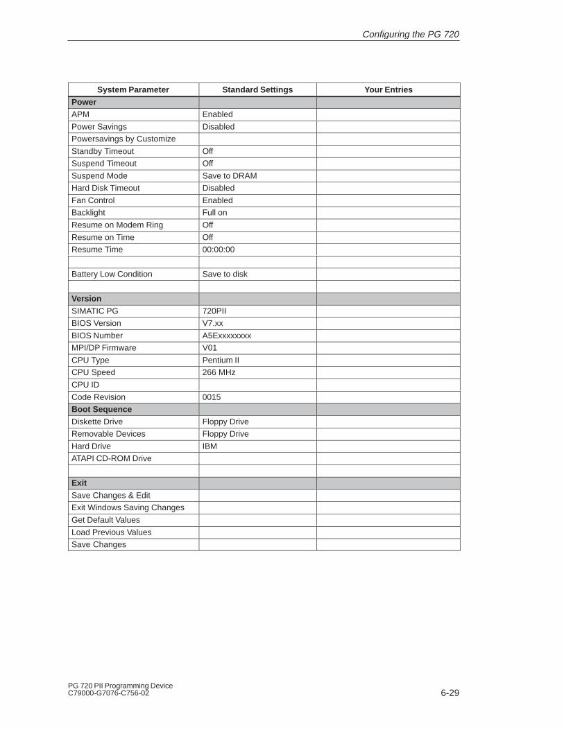
6-29PG 720 PII Programming DeviceC79000-G7076-C756-02
System Parameter Your EntriesStandard Settings
PowerAPM Enabled
Power Savings Disabled
Powersavings by Customize
Standby Timeout Off
Suspend Timeout Off
Suspend Mode Save to DRAM
Hard Disk Timeout Disabled
Fan Control Enabled
Backlight Full on
Resume on Modem Ring Off
Resume on Time Off
Resume Time 00:00:00
Battery Low Condition Save to disk
Version
SIMATIC PG 720PII
BIOS Version V7.xx
BIOS Number A5Exxxxxxxx
MPI/DP Firmware V01
CPU Type Pentium II
CPU Speed 266 MHz
CPU ID
Code Revision 0015
Boot Sequence
Diskette Drive Floppy Drive
Removable Devices Floppy Drive
Hard Drive IBM
ATAPI CD-ROM Drive
Exit
Save Changes & Edit
Exit Windows Saving Changes
Get Default Values
Load Previous Values
Save Changes
Configuring the PG 720
6-30PG 720 PII Programming Device
C79000-G7076-C756-02
6.2 Configuring the PC Card Interface
You can obtain the software you require for using PC cards underMS-DOS, such as
� Socket Services
� Card Services
� Client Drivers
� Flash File System
from your nearest Siemens sales office or representative.
Your programming device comes supplied with Windows 98 alreadyinstalled; this supports the PC card interface.
Configuring the PG 720

7-1PG 720 PII Programming DeviceC79000-G7076-C756-02
Error Diagnostics
This chapter will help you to locate, identify, and in some caseseliminate simple errors and faults. The symptoms of the problem,possible causes, and remedies are listed in the form of a table.
What Does ThisChapter Contain?
7

7-2PG 720 PII Programming Device
C79000-G7076-C756-02
Table 7-1 Errors/Faults in PG 720 Operation
Error/Fault Cause Remedy
Power- LED does not light up � PG 720 is switched off
� Power supply not properlyconnected
� Battery run down
� Switch the unit on
� Check the power supply,power cable, and powerconnector
� Charge or replace battery
Display remains dark afterpower up
� Back lighting is not active � Wait 3 to 5 seconds until theback lighting is active
External monitor remains dark � LCD enabled is entered inSETUP
� Enter CRT enabled orSIMULTAN in SETUP
Message on the display:
“Invalid configurationinformation... Press the F1 keyfor continue, F2 to run Setuputility”
� Incorrect configuration data � Press “F2” key, check theconfiguration data in theSETUP program, if necessaryadapt the default values, andcheck the error messages inthe first SETUP menu
Message on the display: “Noboot device available” NTDLRnot found, check boot datacarrier
� Diskette in drive A: is not aboot diskette
� Wrong hard disk type enteredin SETUP
� Replace diskette with bootdiskette
� Use the “Autotype Fixed Disk”function
Message: “Keyboard stuck keyfailure”
� A key became blocked duringthe self-test of the keyboard
� Check the keyboard
� Restart the system
Booting of the PG 720 abortedwith a series of beeps
� Error occurred during theself-test
� Battery charge too low
� Check hardware
� Charge battery, or connect tomains power
Every time a key is pressed, abeep is heard and no characterappears
� Keyboard buffer overflow � <CTRL> <PAUSE>
Not ready message whenattempting to read a diskette
� No diskette inserted
� Diskette is not formatted
� Insert diskette
� Format diskette
Read-only error whenattempting to write to adiskette
� Diskette is read-only
� Read-only hole open on 3.5’’diskette
� Cancel the write protection
<\> key does not exist � Wrong keyboard driver isbeing used
� German keyboard: <ALTGr> <ß>
� International keyboard: <\> key
Mouse pointer cannot bemoved with the trackball
� The ball is not rotating
� No or wrong mouse driver
� Clean the trackball and itshousing
� Load the correct mouse driver
Mouse pointer movingerratically
� Trackball dirty � Clean the trackball and itshousing
Error Diagnostics
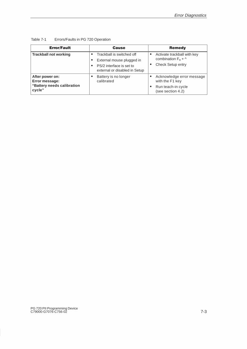
7-3PG 720 PII Programming DeviceC79000-G7076-C756-02
Table 7-1 Errors/Faults in PG 720 Operation
Error/Fault RemedyCause
Trackball not working � Trackball is switched off
� External mouse plugged in
� PS/2 interface is set toexternal or disabled in Setup
� Activate trackball with keycombination Fn + ^
� Check Setup entry
After power on:Error message:“Battery needs calibrationcycle”
� Battery is no longercalibrated
� Acknowledge error messagewith the F1 key
� Run teach-in cycle(see section 4.2)
Error Diagnostics

7-4PG 720 PII Programming Device
C79000-G7076-C756-02
7.1 Programming Device Self-Test Prior to Booting
When the PG 720 is powered up, it runs a self-test (POST = Power OnSelf Test).
If the POST detects a fault, it outputs the sequence of beeps (beepcode) assigned for the fault.
Each beep code consists of 2 x 2 sequences.
Conversion table for the beep codes to hexadecimal representation:
Beeps Hex Code
B B 0
B BB 1
B BBB 2
B BBBB 3
BB B 4
BB BB 5
BB BBB 6
BB BBBB 7
BBB B 8
BBB BB 9
BBB BBB A
BBB BBBB B
BBBB B C
BBBB BB D
BBBB BBB E
BBBB BBBB F
Example:
Beeps
B BBBB BB BBB
3 6
Check shutdown code
Error Diagnostics
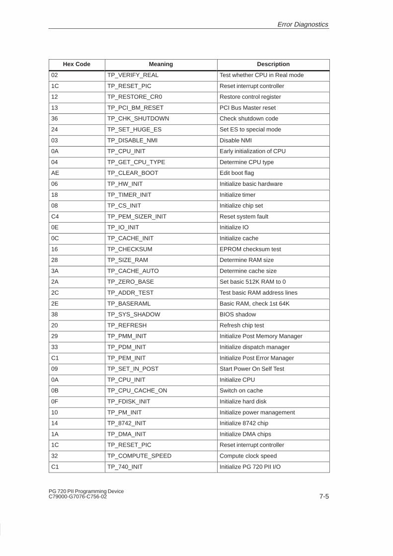
7-5PG 720 PII Programming DeviceC79000-G7076-C756-02
Hex Code Meaning Description
02 TP_VERIFY_REAL Test whether CPU in Real mode
1C TP_RESET_PIC Reset interrupt controller
12 TP_RESTORE_CR0 Restore control register
13 TP_PCI_BM_RESET PCI Bus Master reset
36 TP_CHK_SHUTDOWN Check shutdown code
24 TP_SET_HUGE_ES Set ES to special mode
03 TP_DISABLE_NMI Disable NMI
0A TP_CPU_INIT Early initialization of CPU
04 TP_GET_CPU_TYPE Determine CPU type
AE TP_CLEAR_BOOT Edit boot flag
06 TP_HW_INIT Initialize basic hardware
18 TP_TIMER_INIT Initialize timer
08 TP_CS_INIT Initialize chip set
C4 TP_PEM_SIZER_INIT Reset system fault
0E TP_IO_INIT Initialize IO
0C TP_CACHE_INIT Initialize cache
16 TP_CHECKSUM EPROM checksum test
28 TP_SIZE_RAM Determine RAM size
3A TP_CACHE_AUTO Determine cache size
2A TP_ZERO_BASE Set basic 512K RAM to 0
2C TP_ADDR_TEST Test basic RAM address lines
2E TP_BASERAML Basic RAM, check 1st 64K
38 TP_SYS_SHADOW BIOS shadow
20 TP_REFRESH Refresh chip test
29 TP_PMM_INIT Initialize Post Memory Manager
33 TP_PDM_INIT Initialize dispatch manager
C1 TP_PEM_INIT Initialize Post Error Manager
09 TP_SET_IN_POST Start Power On Self Test
0A TP_CPU_INIT Initialize CPU
0B TP_CPU_CACHE_ON Switch on cache
0F TP_FDISK_INIT Initialize hard disk
10 TP_PM_INIT Initialize power management
14 TP_8742_INIT Initialize 8742 chip
1A TP_DMA_INIT Initialize DMA chips
1C TP_RESET_PIC Reset interrupt controller
32 TP_COMPUTE_SPEED Compute clock speed
C1 TP_740_INIT Initialize PG 720 PII I/O
Error Diagnostics

7-6PG 720 PII Programming Device
C79000-G7076-C756-02
Hex Code DescriptionMeaning
3C TP_ADV_CS_CONFIG Configure advanced chip set
42 TP_VECTOR_INIT Initialize interrupt vectors
46 TP_COPYRIGHT Check copyright
49 TP_PCI_INIT Initialize PCI interface
48 TP_CONFIG Check configuration
4A TP_VIDEO Initialize video interface
If the INSERT key is pressed during booting of the system, three shortbeeps are sounded. This signalizes that the initialization of the specialprogramming device hardware is being skipped.
If your PG 720 does not boot correctly, you can inform the hotline ofthe POST hex code.
Error Diagnostics
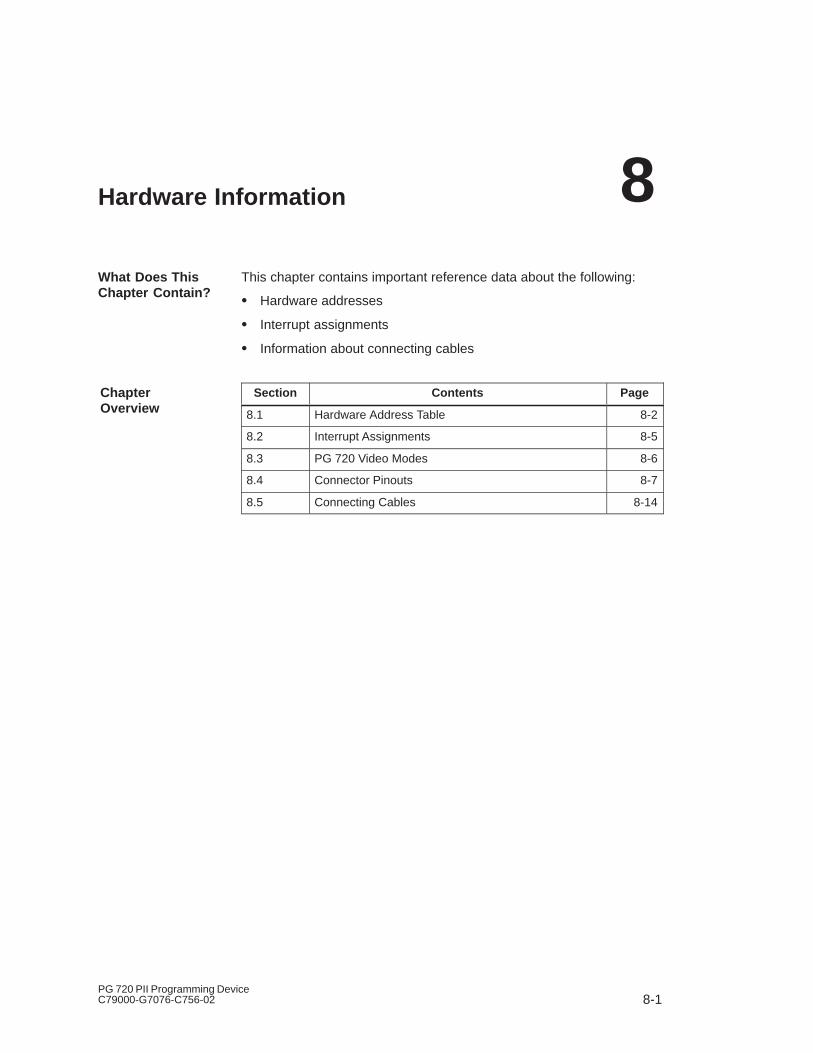
8-1PG 720 PII Programming DeviceC79000-G7076-C756-02
Hardware Information
This chapter contains important reference data about the following:
� Hardware addresses
� Interrupt assignments
� Information about connecting cables
Section Contents Page
8.1 Hardware Address Table 8-2
8.2 Interrupt Assignments 8-5
8.3 PG 720 Video Modes 8-6
8.4 Connector Pinouts 8-7
8.5 Connecting Cables 8-14
What Does ThisChapter Contain?
ChapterOverview
8
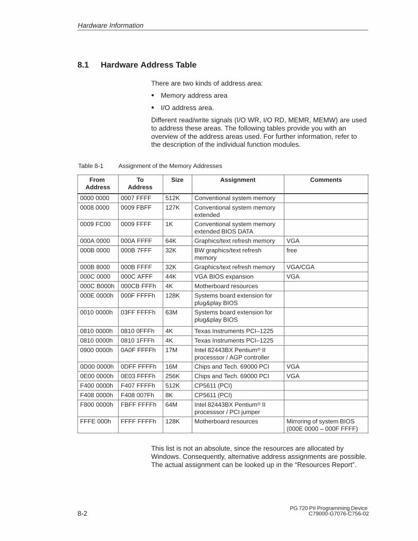
8-2PG 720 PII Programming Device
C79000-G7076-C756-02
8.1 Hardware Address Table
There are two kinds of address area:
� Memory address area
� I/O address area.
Different read/write signals (I/O WR, I/O RD, MEMR, MEMW) are usedto address these areas. The following tables provide you with anoverview of the address areas used. For further information, refer tothe description of the individual function modules.
Table 8-1 Assignment of the Memory Addresses
From Address
ToAddress
Size Assignment Comments
0000 0000 0007 FFFF 512K Conventional system memory
0008 0000 0009 FBFF 127K Conventional system memoryextended
0009 FC00 0009 FFFF 1K Conventional system memoryextended BIOS DATA
000A 0000 000A FFFF 64K Graphics/text refresh memory VGA
000B 0000 000B 7FFF 32K BW graphics/text refreshmemory
free
000B 8000 000B FFFF 32K Graphics/text refresh memory VGA/CGA
000C 0000 000C AFFF 44K VGA BIOS expansion VGA
000C B000h 000CB FFFh 4K Motherboard resources
000E 0000h 000F FFFFh 128K Systems board extension forplug&play BIOS
0010 0000h 03FF FFFFh 63M Systems board extension forplug&play BIOS
0810 0000h 0810 0FFFh 4K Texas Instruments PCI–1225
0810 0000h 0810 1FFFh 4K Texas Instruments PCI–1225
0900 0000h 0A0F FFFFh 17M Intel 82443BX Pentium� IIprocesssor / AGP controller
0D00 0000h 0DFF FFFFh 16M Chips and Tech. 69000 PCI VGA
0E00 0000h 0E03 FFFFh 256K Chips and Tech. 69000 PCI VGA
F400 0000h F407 FFFFh 512K CP5611 (PCI)
F408 0000h F408 007Fh 8K CP5611 (PCI)
F800 0000h FBFF FFFFh 64M Intel 82443BX Pentium� IIprocesssor / PCI jumper
FFFE 000h FFFF FFFFh 128K Motherboard resources Mirroring of system BIOS(000E 0000 – 000F FFFF)
This list is not an absolute, since the resources are allocated byWindows. Consequently, alternative address assignments are possible.The actual assignment can be looked up in the “Resources Report”.
Hardware Information
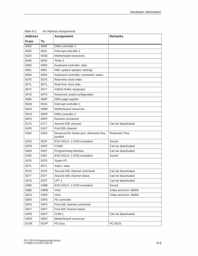
8-3PG 720 PII Programming DeviceC79000-G7076-C756-02
Table 8-2 I/O Address Assignments
Address Assignment Remarks
From To0000 000F DMA controller 1
0020 0021 Interrupt controller 1
0024 003D Motherboard resources
0040 0043 Timer 1
0060 0060 Keyboard controller, data
0061 0061 NMI, system speaker settings
0064 0064 Keyboard controller, command, status
0070 0070 Real-time clock index
0071 0071 Real-time clock date
0072 0077 CMOS-RAM / keyboard
0078 0079 Reserved, board configuration
0080 008F DMA page register
00A0 00A1 Interrupt controller 2
00A4 00B9 Motherboard resources
00C0 00DF DMA controller 2
00F0 00FF Numeric processor
0170 0177 Second IDE channel Can be deactivated
01F0 01F7 First IDE channel
0200 0203 Reserved for Game port, otherwise free,joystick
Reserved / free
0220 022F ESS SOLO -1 DOS emulation Sound
02F8 02FF COM2 Can be deactivated
0300 031F Programming interface Can be deactivated
0330 0331 ESS SOLO -1 DOS emulation Sound
0370 0370 Super I/O
0371 0371 Index / data
0376 0376 Second IDE channel command Can be deactivated
0377 0377 Second IDE channel status Can be deactivated
0378 037F LPT 1 Can be deactivated
0388 038B ESS SOLO -1 DOS emulation Sound
03B0 03BB VGA Chips and tech. 69000
03C0 03DF VGA Chips and tech. 69000
03F0 03F5 FD controller
03F6 03F6 First IDE channel command
03F7 03F7 First IDE channel status
03F8 03FF COM 1 Can be deactivated
04D0 04D1 Motherboard resources
0CF8 0CFF PCI bus PCI BUS
Hardware Information

8-4PG 720 PII Programming Device
C79000-G7076-C756-02
Table 8-2 I/O Address Assignments
Address Assignment Remarks
From To
1000 103F PIIX IO
1040 104F PIIX power management
1050 1057 First IDE controller (dual FIFO)
1058 105F Second IDE controller (dual FIFO)
1060 107F PCI/USB universal host controller
1080 10E7 ESS SOLO -1 audio device Sound
Table 8-3 DMA Assignments
DMA Channel Data Transfer Description
0 8 / 16 bits Unoccupied
1 8 / 16 bit ESS SOLO -1 DOS emulation (sound)
2 8 / 16 bits Floppy
3 8 / 16 bits Unoccupied
4 Cascading of DMA controllers
5 16 bits Unoccupied
6 16 bits Unoccupied
7 16 bits Unoccupied
Hardware Information

8-5PG 720 PII Programming DeviceC79000-G7076-C756-02
8.2 Interrupt Assignments
The PG 720 uses the two integrated interrupt controllers of type 82C59to handle the 16 hardware interrupts (IRQ 0 to IRQ 15).The INT output of the slave controller is connected to the IRQ 2 input ofthe master controller. Interrupt 9 (IRQ 9) can be used on the bus for theassigned interrupt 2 (IRQ 2). In the initialization phase, IRQ 9 is assignedto the software interrupt vector 0A H (IRQ 2) by the ROM-BIOS.
The priority of the interrupts is in the reverse order of their numbering. Thismeans the following: Interrupt IRQ 0 has the highest priority and interruptIRQ 7 the lowest. For triggering IRQ 2, interrupt IRQ 8 has the highest andIRQ 15 the lowest priority. Interrupts IRQ 8 to IRQ 15 therefore havehigher priority than interrupts IRQ 3 to IRQ 7. The interrupt vectors areinitialized and masked when the PG 720 is powered up.
Interrupt Description Comment Vector
SMI System management interrupt, cannotbe masked
- –
NMI Expansion slots signal I/O channelcheck 2
Fixed INT 2 H
IRQ 0 Internal timer (system clock) Fixed INT 8 H
IRQ 1 Keyboard Fixed INT 9 H
IRQ 2 Cascading from interrupt controller 2 Fixed INT A H
IRQ 3 Serial port 2 (COM2) Can beswitched off *)
INT B H
IRQ 4 Serial interface 1 (COM1/TTY) Can beswitched off *)
INT C H
IRQ 5 Sound, Cardbus controller SLOT 1 P&P **) INT D H
IRQ 6 Floppy controller Fixed INT E H
IRQ 7 Parallel port 1 (printer port LPT 1/EPP/ECP)
Can beswitched off *)
INT F H
IRQ 8 Battery-backed real-time clock (RTC) Fixed INT 70 H
IRQ 9 VGA controller generallyvacant
INT 71 H
IRQ 10 Cardbus controller Fixed INT 72 H
IRQ 11 USB, Cardbus controller SLOT 2 Fixed INT 73 H
IRQ 12 PS/2 mouse or trackball in keyboard Can beswitched off *)
INT 74 H
IRQ 13 Math coprocessor error Fixed INT 75 H
IRQ 14 IDE interface (primary) Fixed INT 76 H
IRQ 15 IDE controller (secondary) Fixed INT 77 H
Note the interrupts which are already occupied in the system.
*) These components can be disabled via the BIOS SETUP. Thefunctions are then no longer available and the resources arereleased for other components.
**) The on-board MPI/DP interface is plug&play-capable, theoccupied resources are managed by the BIOS.
InterruptAssignment
Priority
I/O Addresses ofthe InterruptControllers
Hardware Information
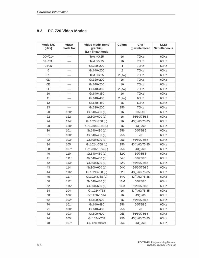
8-6PG 720 PII Programming Device
C79000-G7076-C756-02
8.3 PG 720 Video Modes
Mode No.(Hex)
VESAmode No.
Video mode (text/graphic)
(L) = linear mode
Colors CRT(I) = Interlaced
LCD/Simultaneous
00+/01+ –– Text 40x25 16 70Hz 60Hz
02+/03+ –– Text 80x25 16 70Hz 60Hz
04/05 –– Gr.320x200 4 70Hz 60Hz
6 –– Gr.640x200 2 70Hz 60Hz
07+ –– Text 80x25 2 (sw) 70Hz 60Hz
0D –– Gr.320x200 16 70Hz 60Hz
0E –– Gr.640x200 16 70Hz 60Hz
0F –– Gr.640x350 2 (sw) 70Hz 60Hz
10 –– Gr.640x350 16 70Hz 60Hz
11 –– Gr.640x480 2 (sw) 60Hz 60Hz
12 –– Gr.640x480 16 60Hz 60Hz
13 –– Gr.320x200 256 70Hz 60Hz
20 120h Gr.640x480 (L) 16 60/75/85 60Hz
22 122h Gr.800x600 (L) 16 56/60/75/85 60Hz
24 124h Gr.1024x768 (L) 16 43(I)/60/75/85 60Hz
28 128h Gr.1280x1024 (L) 16 43(I)/60 60Hz
30 101h Gr.640x480 (L) 256 60/75/85 60Hz
31 100h Gr.640x400 (L) 256 70 60Hz
32 103h Gr.800x600 (L) 256 56/60/75/85 60Hz
34 105h Gr.1024x768 (L) 256 43(I)/60/75/85 60Hz
38 107h Gr.1280x1024 (L) 256 43(I)/60 60Hz
40 110h Gr.640x480 (L) 32K 60/75/85 60Hz
41 111h Gr.640x480 (L) 64K 60/75/85 60Hz
42 113h Gr.800x600 (L) 32K 56/60/75/85 60Hz
43 114h Gr.800x600 (L) 64K 56/60/75/85 60Hz
44 116h Gr.1024x768 (L) 32K 43(I)/60/75/85 60Hz
45 117h Gr.1024x768 (L) 64K 43(I)/60/75/85 60Hz
50 112h Gr.640x480 (L) 16M 60/75/85 60Hz
52 115h Gr.800x600 (L) 16M 56/60/75/85 60Hz
64 104h Gr.1024x768 16 43(I)/60/75/85 60Hz
68 106h Gr.1280x1024 16 43(I)/60 60Hz
6A 102h Gr.800x600 16 56/60/75/85 60Hz
70 101h Gr.640x480 256 60/75/85 60Hz
71 100h Gr.640x480 256 70 60Hz
72 103h Gr.800x600 256 56/60/75/85 60Hz
74 105h Gr.1024x768 256 43(I)/60/75/85 60Hz
78 107h Gr. 1280x1024 256 43(I)/60 60Hz
Hardware Information

8-7PG 720 PII Programming DeviceC79000-G7076-C756-02
8.4 Connector Pinouts
The socket for the external power supply unit has the followingpotentials:
+ 17.5 V +5% DC voltage
– 0 V Ground
Figure 8-1 Power Supply Connector
You can connect a PS/2 mouse to your PG 720. The connector has thefollowing pinout:
View of the socket connector
��
��
��
Figure 8-2 Connector Pinout for the PS/2 Mouse Cable
Pin No. Designation Input/Output
1 Data line Input/output
2 Not assigned –
3 0 V –
4 Current-limited 5V power supply Output
5 Clock line Input/output
6 Not assigned –
Socket Connectorfor the ExternalPower Unit
Connecting a PS/2Mouse
Hardware Information
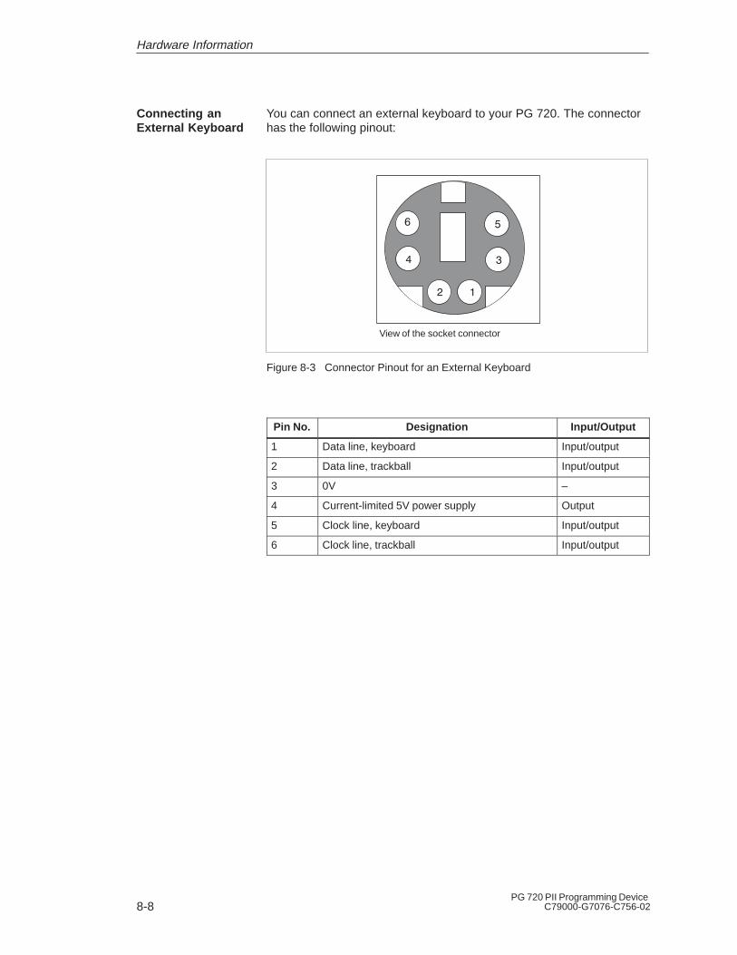
8-8PG 720 PII Programming Device
C79000-G7076-C756-02
You can connect an external keyboard to your PG 720. The connectorhas the following pinout:
View of the socket connector
��
��
��
Figure 8-3 Connector Pinout for an External Keyboard
Pin No. Designation Input/Output
1 Data line, keyboard Input/output
2 Data line, trackball Input/output
3 0V –
4 Current-limited 5V power supply Output
5 Clock line, keyboard Input/output
6 Clock line, trackball Input/output
Connecting anExternal Keyboard
Hardware Information
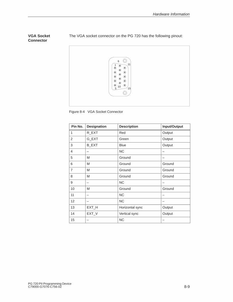
8-9PG 720 PII Programming DeviceC79000-G7076-C756-02
The VGA socket connector on the PG 720 has the following pinout:
1
5
6
10
11
15
Figure 8-4 VGA Socket Connector
Pin No. Designation Description Input/Output
1 R_EXT Red Output
2 G_EXT Green Output
3 B_EXT Blue Output
4 – NC –
5 M Ground –
6 M Ground Ground
7 M Ground Ground
8 M Ground Ground
9 – NC –
10 M Ground Ground
11 – NC –
12 – NC –
13 EXT_H Horizontal sync Output
14 EXT_V Vertical sync Output
15 – NC –
VGA SocketConnector
Hardware Information
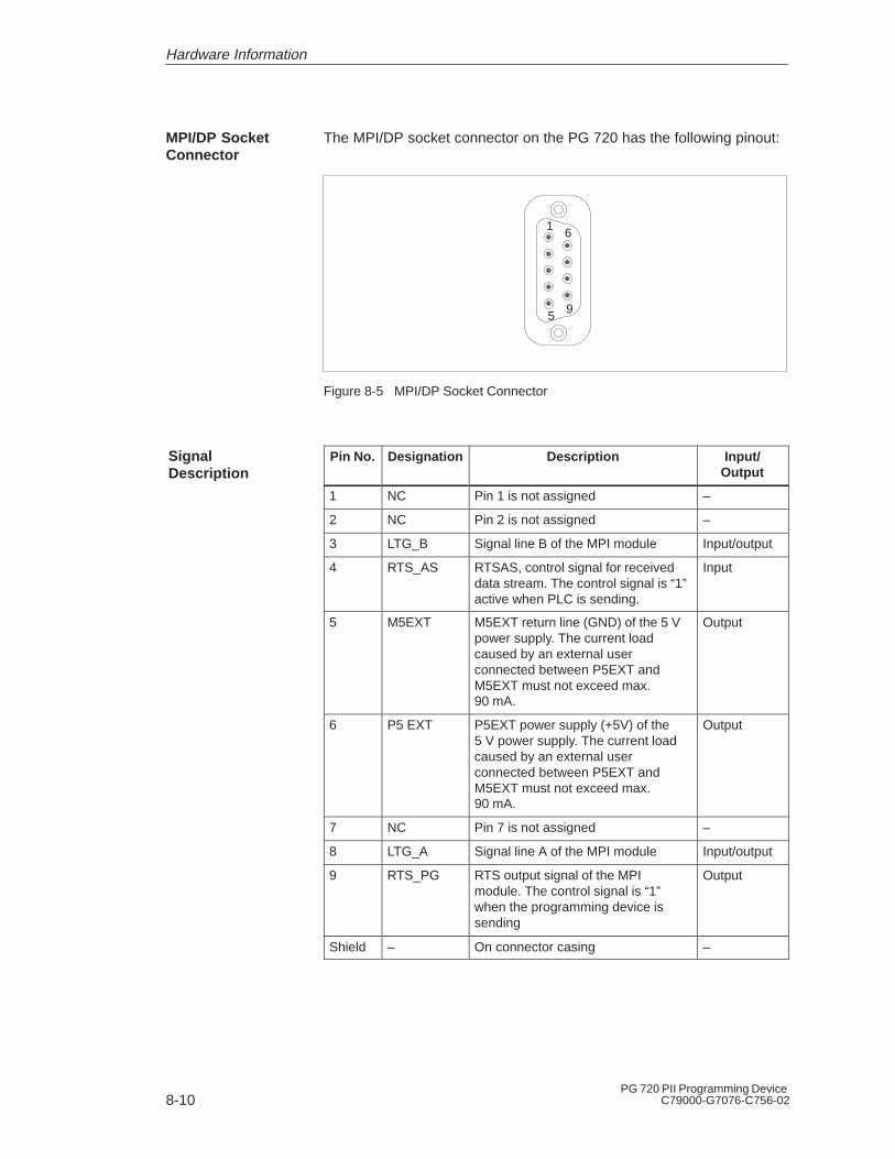
8-10PG 720 PII Programming Device
C79000-G7076-C756-02
The MPI/DP socket connector on the PG 720 has the following pinout:
1
5
6
9
Figure 8-5 MPI/DP Socket Connector
Pin No. Designation Description Input/Output
1 NC Pin 1 is not assigned –
2 NC Pin 2 is not assigned –
3 LTG_B Signal line B of the MPI module Input/output
4 RTS_AS RTSAS, control signal for receiveddata stream. The control signal is “1”active when PLC is sending.
Input
5 M5EXT M5EXT return line (GND) of the 5 Vpower supply. The current loadcaused by an external userconnected between P5EXT andM5EXT must not exceed max.90 mA.
Output
6 P5 EXT P5EXT power supply (+5V) of the5 V power supply. The current loadcaused by an external userconnected between P5EXT andM5EXT must not exceed max.90 mA.
Output
7 NC Pin 7 is not assigned –
8 LTG_A Signal line A of the MPI module Input/output
9 RTS_PG RTS output signal of the MPImodule. The control signal is “1”when the programming device issending
Output
Shield – On connector casing –
MPI/DP SocketConnector
SignalDescription
Hardware Information
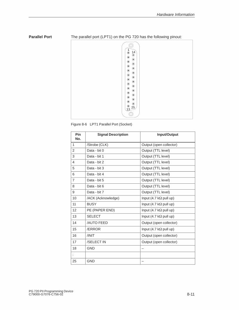
8-11PG 720 PII Programming DeviceC79000-G7076-C756-02
The parallel port (LPT1) on the PG 720 has the following pinout:
1
13
14
25
Figure 8-6 LPT1 Parallel Port (Socket)
PinNo.
Signal Description Input/Output
1 /Strobe (CLK) Output (open collector)
2 Data - bit 0 Output (TTL level)
3 Data - bit 1 Output (TTL level)
4 Data - bit 2 Output (TTL level)
5 Data - bit 3 Output (TTL level)
6 Data - bit 4 Output (TTL level)
7 Data - bit 5 Output (TTL level)
8 Data - bit 6 Output (TTL level)
9 Data - bit 7 Output (TTL level)
10 /ACK (Acknowledge) Input (4.7 k� pull up)
11 BUSY Input (4.7 k� pull up)
12 PE (PAPER END) Input (4.7 k� pull up)
13 SELECT Input (4.7 k� pull up)
14 /AUTO FEED Output (open collector)
15 /ERROR Input (4.7 k� pull up)
16 /INIT Output (open collector)
17 /SELECT IN Output (open collector)
18 GND –
:
25 GND –
Parallel Port
Hardware Information
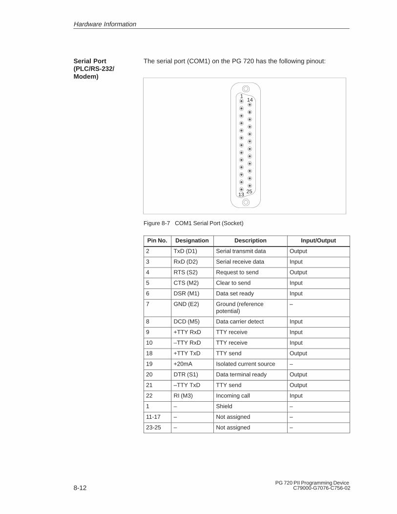
8-12PG 720 PII Programming Device
C79000-G7076-C756-02
The serial port (COM1) on the PG 720 has the following pinout:
1
13
14
25
Figure 8-7 COM1 Serial Port (Socket)
Pin No. Designation Description Input/Output
2 TxD (D1) Serial transmit data Output
3 RxD (D2) Serial receive data Input
4 RTS (S2) Request to send Output
5 CTS (M2) Clear to send Input
6 DSR (M1) Data set ready Input
7 GND (E2) Ground (referencepotential)
–
8 DCD (M5) Data carrier detect Input
9 +TTY RxD TTY receive Input
10 –TTY RxD TTY receive Input
18 +TTY TxD TTY send Output
19 +20mA Isolated current source –
20 DTR (S1) Data terminal ready Output
21 –TTY TxD TTY send Output
22 RI (M3) Incoming call Input
1 – Shield –
11-17 – Not assigned –
23-25 – Not assigned –
Serial Port(PLC/RS-232/Modem)
Hardware Information

8-13PG 720 PII Programming DeviceC79000-G7076-C756-02
The serial port (COM2) on the PG 720 has the following pinout:
1
5
6
9
Figure 8-8 COM2 Serial Port (Connector)
PinNo.
Designation Description Input/Output
1 DCD (M5) Data carrier detect Input
2 RxD (D2) Receive data Input
3 TxD (D1) Transmit data Output
4 DTR (S1) Data terminal ready Output
5 GND (E2) Ground –
6 DSR (M1) Data set ready Input
7 RTS (S2) Request to send Output
8 CTS (M2) Clear to send Input
9 RI (M3) Incoming call Input
The pin assignment of the Universal Serial Bus port is as follows:
Table 8-4 Universal Serial Bus Port
Pin No. Signalname
Meaning
4
1 VCC Cable power
4
3
2
2 – Data
23 + Data
14 Ground Cable ground
The plug is a type A connector.
Serial Port(RS-232/Mouse)
USB Port
Hardware Information

8-14PG 720 PII Programming Device
C79000-G7076-C756-02
8.5 Connecting Cables
PG 6xx
PG 7xx
S5-90U to S5-155U
S5-150U (AS 511)
Printer
CP523-525
CP526, 527CP530, 143CP552, 580CP581IP252, 260IP246, 247
S7 x00
COM1/TTY
COM1/TTY
COM1/TTY
COM1/RS-232
LPT1/Centronics
COM1/RS-232
PLC-SS/TTY
PG-IF/TTY
15-pin PG IF
25-pin PG IF
Centronics
MPI/RS 485 MPI conn./RS 485
PG-IF/MPI/RS 485
ET200 conn./RS 485
6ES5731-6AG00
6ES5733-2xxx0
6ES5733-5xxx0
Link via RS-232
6ES5731-6AG00
6ES5731-1xxx0
6ES5731-6AG00
6ES5731-0xxx0
6AP1901-0AL00
6ES5731-6AG00
6ES5726-0xxx0
6ES5731-6AG00
6ES5731-1xxx0
6ES5734-2xxx0
6ES7901-0BF00-0AA0
and
and
and
and
and
or
6ES5734-2xxx0or
Figure 8-9 Connecting Cables
1) Connecting cables available as spare parts only
Overview
Hardware Information

8-15PG 720 PII Programming DeviceC79000-G7076-C756-02
Using the standard connecting cable (supplied with the unit) you canconnect your PG 720 to a Siemens programmable logic controller.Please refer to the information in Chapter 3.
PG 7xx
25-pin male connector
activated
Connecting cable
6ES5 734-2BD20
(supplied)
PLC
15-pin male connector
deactivated
19
18
21
19
9
2
6
330 ohms
330 ohms
9
10
7
8
1
1
3
20
CasingShield/
casing
+V
–V
+V
–V
Figure 8-10 Standard Connecting Cable
If you want to connect your PG 720 to a programmable logic controllerusing the standard connecting cable of a PG 6xx, use an adapter.
PG 7xx
25-pin male
activated
Adapter
6ES5 731-6AG00
(Release 2)
Connecting cable
6ES5 731-1xxx0
PLC
15-pin male
deactivated
330 ohms
330 ohms
19
18
21
22
10
9
2
19 8 6
7219
10 24
251223206234
17
8
1
1
3
20
Casing
ShieldCasing
+V
–V
+V
–V
Figure 8-11 Adapter for PG 6xx Cable
StandardConnecting Cable
Adapter forPG 6xx Cable
Hardware Information

8-16PG 720 PII Programming Device
C79000-G7076-C756-02
PG 7xx PG 695 II25-pin male
activated
Adapter6ES5 731-6AG00(Release 2)
Connecting cable6ES5 731-0xxx0
S5-PLC, V.2425-pin femaledeactivated
330 ohms
330 ohms
19
18
21
22
10
9
819
21
19
1821
20
10
20
20
1
3
24
251223
6234
17
1
24
25
Shield
Casing
+V
+V
–V
–V
Figure 8-12 Connecting Cable With 25-Pin Socket Connector
You can connect your PG 720 to other programming devices with thiscable using the TTY/COM1 interface. This cable does not have anorder number. Please read the notes in Chapter 4.
PG 7xxPG 695 II (PC 16-20)25-pin male Cannon connector
activated
25-pin male Cannon connector
PG 7xxPG 695 II (PC 16-20)
deactivated
330 ohms19
18
21
9
10
330 ohms19 18
219
10
1
3
20 20
3
Shield/casing
COM1/TTY port COM1/TTY port
+V
–V
+V
–V
Figure 8-13 Cable for Interconnecting Programming Devices
Connecting CableWith 25-Pin SocketConnector
Cable forInterconnectingProgrammingDevices
Hardware Information
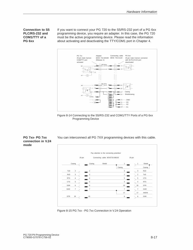
8-17PG 720 PII Programming DeviceC79000-G7076-C756-02
If you want to connect your PG 720 to the S5/RS-232 port of a PG 6xxprogramming device, you require an adapter. In this case, the PG 720must be the active programming device. Please read the informationabout activating and deactivating the TTY/COM1 port in Chapter 4.
PG 7xx25-pin male Cannon 25-pin male Cannon connectorCOM/TTY portactivated
Adapter6ES5 731-6AG00(Release 2)
Connecting cable6ES5 733-2xxx0
PG 6xx
with S5 PLC/V.24 portdeactivated
330 ohms
330 ohms
19
18
21
22
10
6
8
19
9
8
21
10
12
10 24
25122320623417
24
25
2
34
17
1
3
20
Casing
Casing
Shield/casing
GND
K3K2
K1
+V
–V
+V
–V
Figure 8-14 Connecting to the S5/RS-232 and COM1/TTY Ports of a PG 6xx Programming Device
You can interconnect all PG 7XX programming devices with this cable.
Casing Shield
Casing Casing
ShieldCasing 1
3
2
5
4
20
7
17
6
RxD
TxD
CTS
RTS
DTR
GHD
AKENI
DSR
2
3
4
5
6
7
20
TxD
RxD
RTS
CTS
DSR
GHD
DTR
2
3
4
5
6
7
20
1
3
2
5
4
20
7
17
6
25-pin 25-pinConnecting cable: 6ES5733-0BD20
Pay attention to the connecting polarities!
Figure 8-15 PG 7xx - PG 7xx Connection in V.24 Operation
Connection to S5PLC/RS-232 andCOM1/TTY of aPG 6xx
PG 7xx- PG 7xxconnection in V.24mode
Hardware Information

8-18PG 720 PII Programming Device
C79000-G7076-C756-02
Hardware Information

A-1PG 720 PII Programming DeviceC79000-G7076-C756-02
Guidelines for HandlingElectrostatically-Sensitive Devices (ESD)
Section Contents Page
A.1 What is ESD? A-2
A.2 Electrostatic Charging of Persons A-3
A.3 General Protective Measures Against ElectrostaticDischarge Damage
A-4
ChapterOverview
A
A-2PG 720 PII Programming Device
C79000-G7076-C756-02
A.1 What is ESD?
All electronic modules are equipped with large-scale integrated ICs orcomponents. Due to their design, these electronic elements are verysensitive to overvoltages and thus to any electrostatic discharge.
These Electrostatically-Sensitive Devices are commonly referred to bythe abbreviation ESD.
Electrostatically-sensitive devices are labeled with the following symbol:
!Caution
Electrostatically-sensitive devices are subject to voltages that are farbelow the voltage values that can still be perceived by human beings.These voltages are present if you touch a component or the electricalconnections of a module without previously being electrostaticallydischarged. In most cases, the damage caused by an overvoltage isnot immediately noticeable and results in total damage only after aprolonged period of operation.
Definition
Guidelines for Handling Electrostatically-Sensitive Devices (ESD)
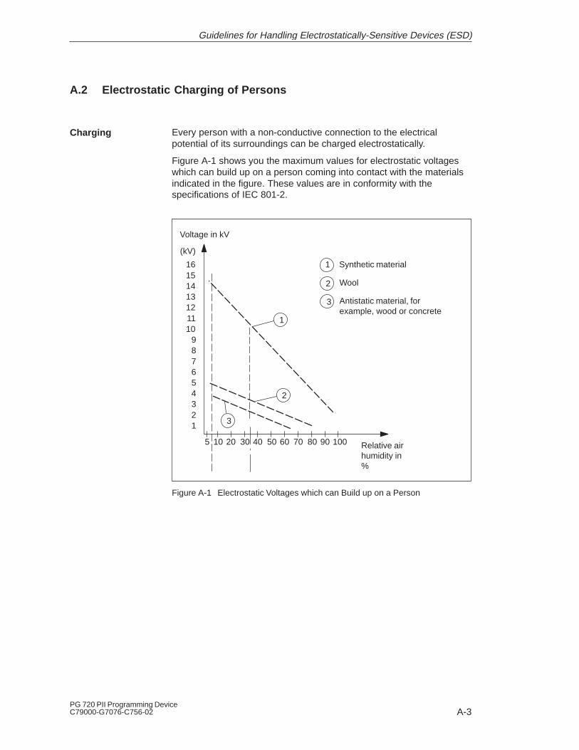
A-3PG 720 PII Programming DeviceC79000-G7076-C756-02
A.2 Electrostatic Charging of Persons
Every person with a non-conductive connection to the electricalpotential of its surroundings can be charged electrostatically.
Figure A-1 shows you the maximum values for electrostatic voltageswhich can build up on a person coming into contact with the materialsindicated in the figure. These values are in conformity with thespecifications of IEC 801-2.
Voltage in kV
123456789
10111213141516
(kV)
5 10 20 30 40 50 60 70 80 90 100 Relative airhumidity in%
1
3
1 Synthetic material
2 Wool
3 Antistatic material, forexample, wood or concrete
2
Figure A-1 Electrostatic Voltages which can Build up on a Person
Charging
Guidelines for Handling Electrostatically-Sensitive Devices (ESD)

A-4PG 720 PII Programming Device
C79000-G7076-C756-02
A.3 General Protective Measures Against Electrostatic DischargeDamage
Make sure that the personnel, working surfaces, and packaging aresufficiently grounded when handling electrostatically-sensitive devices.You thus avoid electrostatic charging.
You should touch electrostatically-sensitive devices only if it isunavoidable (for example, during maintenance work). Hold moduleswithout touching the pins of components or printed conductors. In thisway, the discharged energy cannot affect the sensitive devices.
If you have to carry out measurements on a module, you mustdischarge your body before you start the measurement by touchinggrounded metallic parts. Use grounded measuring devices only.
Ensure SufficientGrounding
Avoid DirectContact
Guidelines for Handling Electrostatically-Sensitive Devices (ESD)

Glossary-1PG 720 PII Programming DeviceC79000-G7076-C756-02
Glossary
This chapter contains a glossary in which you will find a list of theterminology used in conjunction with the Siemens range ofprogramming devices and a brief explanation of each of the terms.
What does ThisChapter Contain?
Glossary-2PG 720 PII Programming Device
C79000-G7076-C756-02
Access to the programs and data of a programming device can beprotected by passwords.
Advanced Configuration and Power Interface.
Advanced Power Management.
An application is a program which builds directly on, for example, theMS-DOS/Windows operating system. Applications on yourprogramming device are the STEP 5 Basic package, STEP 7, etc.
With an ASCII editor you can process (that is, edit) text files which arestored in ASCII code (American Standard Code of InformationInterchange).
The base memory is a part of the main memory. It is 640 Kbytes for allprogramming devices. The size is entered in the SETUP menu underthe entry “Base Memory” and is not changed even if the memory isextended.
BASIC Input Output System
A diskette which includes a boot sector, enabling it to load theoperating system.
A loading operation which transfers the operating system to the mainmemory.
The speed (in bits per second) with which information is transmittedover a data link.
A
Access Protection
ACPI
APM
Application
ASCII Editor
B
Base Memory
BIOS
Boot Diskette
Booting
Bps
Glossary

Glossary-3PG 720 PII Programming DeviceC79000-G7076-C756-02
This interface is compatible with 32-bit Cardbus cards with PCI perfor-mance compliant with the PC Card standard.
(Compact Disc – Read Only Memory) Removable memory for largeamounts of data.
Pressing and immediately releasing the left mouse button; this selectsobjects or trigger commands.
The COM1 port is a serial V.24/modem-PLC interface. This interface issuitable for asynchronous data transmission. It can also be used toconnect printers with a serial interface.
The COM2 port is a serial RS-232 interface which can be used toconnect a mouse or a printer.
These are files containing data which define the configuration afterbooting. Examples of such files are CONFIG.SYS andAUTOEXEC.BAT.
The configuration software brings the device configuration up-to-datewhen modules are installed. This is done either by copying theconfiguration files supplied with the module or by manual configurationusing the configuration utility.
Collective term for mouse pointer and text cursor.
Keypad on the keyboard for controlling the cursor.
The configuration of a programming device contains information on thehardware and options of the device, such as memory configuration,drive types, monitor, network address, etc. The data are stored in aconfiguration file and enable the operating system to load the correctdevice drivers and assign the correct device parameter assignments.
If changes are made to the hardware configuration, the user canchange entries in the configuration file using the SETUP program.
C
Cardbus interface
CD ROM
Click
COM1 Port
COM2 Port
ConfigurationFiles
Configuration Software
Cursor
Cursor Control
D
Device Configuration
Glossary

Glossary-4PG 720 PII Programming Device
C79000-G7076-C756-02
The disk drive (floppy disk drive) is used to store programs and data ondiskette (write access) or to load from diskette to the computer (readaccess).
The diskette (floppy disk) is an external data access memory on whichall types of files and programs can be stored. The storage medium is around magnetic disk in a plastic cover to protect it from gettingscratched.
The flat monitor of the PG 720.
Pressing and releasing the left mouse button very quickly twice insuccession without moving the mouse. This action is normally to openan object or program.
The PG 720 programming device is equipped with one hard disk driveand one floppy disk drive.
These are programs which are part of the operating system. Theyadapt the data from user programs to the specific formats required bythe I/O devices such as hard disk, printers, and monitors.
In graphics-supported programs, a menu line is positioned on the topedge of the screen. The menu titles contained in this line can be seteither as drop-down or pull-down menus. Drop-down menus “roll” downas soon as the mouse pointer passes over a menu title. Pull-downmenus only “roll” down when the menu title is clicked on. Differentfunctions can then be called from these menus by moving the mouseand clicking on an item in a menu.
These are plug-in submodules with EPROM/EEPROM chips. S5 userprograms can be stored on them. These programmed submodules arethen plugged in specially designed receptacles in the programmablelogic controller.
A memory extension can be installed in a programming device toincrease the size of the memory.
Disk Drive
Diskette
Display
Double-Click
Drives
Drivers
Drop-Down Menu
E
EPROM/EEPROM Submodules
Extended Memory
Glossary

Glossary-5PG 720 PII Programming DeviceC79000-G7076-C756-02
A file is the collection of data under one name.
Formatting divides the memory area on a magnetic data medium intotracks and sectors. Formatting deletes all the data on a data medium.Every data medium must be formatted before it is used for the firsttime.
Function keys can be divided into two different types; the normalfunction keys which are assigned a particular function of the computer(for example, delete key), and programmable function keys (softkeys).
The output of the complete contents of the screen on a printer is calleda hard copy.
Hard disk drives (Winchester drives) are a form of magnetic diskmemory where the magnetic disks are permanently built into the drive.
Bus system based on the Ethernet standard. Components of theSIMATIC S5 and S7 series (programming devices, programmable logiccontrollers, programmable control systems) can be networked usingIndustrial Ethernet interface modules.
� An interface is the connection between individual hardwareelements such as PLCs, programming devices, printers, or monitorsvia physical connections (cables).
� An interface is also the connection between different programs, toenable them to work together.
Module which controls and extends the hardware periphery.
The interruption of program processing in the processor of aprogramming device / programmable controller by an interrupt event.
F
File
Formatting
Function Keys
H
Hard Copy
Hard Disk Drive
I
Industrial Ethernet
Interface
Interface Module
Interrupt
Glossary

Glossary-6PG 720 PII Programming Device
C79000-G7076-C756-02
Interrupt Request Line
Industrial Standard Architecture
(Japanese Electronics Industry Development Association) Associationof Japanese electronics manufacturers whose aim is to set upstandards worldwide for the miniaturization and flexible application ofPC expansion cards. Cooperates with PCMCIA.
The keyboard is the collection of keys which are used to input data,text, characters, letters, numbers, special characters, and controlcommands in a computer. The keyboard forms the input interfacebetween the user and the computer.
Light-emitting diode (for display and indicating purposes).
The LPT1 port (Centronics port) is a parallel interface that can be usedto connect a printer.
The main memory is the complete RAM memory of a programmingdevice.
Memory submodule in credit-card format containing RAMs orEPROMs.
See Extended Memory
Communications device that enables a computer to send and receivedata over a telephone line. Modulator and demodulator of a signaltransmission facility. It converts the digital pulses from a computer intoanalog signals (and vice versa).
IRQ
ISA
J
JEIDA
K
Keyboard
L
LED
LPT1 Port
M
Main Memory
Memory Card
MemoryExpansion
Modem
Glossary
Glossary-7PG 720 PII Programming DeviceC79000-G7076-C756-02
Modules are boards (printed circuit boards) which can be plugged intoa programmable logic controller or programming device. They areavailable, for instance, as central controller modules, interfacemodules, or as bulk memory modules.
The monitor or screen is a visual display unit via which theprogramming device communicates with the user.
The mother board is the core of the programming device. From heredata are processed and stored, interfaces and device I/Os arecontrolled and managed.
The mouse is a pointing device with which the user inputs coordinates(x,y). By moving the mouse, the mouse pointer can be moved at willaround the screen. By pressing the left mouse button, the position ismarked. The other mouse keys may have different assignmentsaccording to the application. With the mouse, objects can be selected,menus processed, and functions started.
The mouse pointer is moved across the worktop (screen) by means ofthe mouse. The mouse pointer selects, for example, objects which areto be processed.
The multipoint interface (MPI) is the programming device interface ofSIMATIC S7. It permits the simultaneous operation of severalprogramming devices, text displays, and operator panels on one ormore central processing units. The stations on the MPI are connectedtogether via a bus system.
(Microsoft Disk Operating System) is one of the standard operatingsystems for personal computers.
Link between programming devices and programmable controllers bymeans of interface modules, physical cables, and the correspondingsoftware to allow data exchange between the devices.
Module
Monitor
Mother Board
Mouse
Mouse Pointer
MPI/DP
MS-DOS
N
Network
Glossary
Glossary-8PG 720 PII Programming Device
C79000-G7076-C756-02
Collective term for all functions which, in conjunction with the hardware,control and monitor execution of the user programs, the distribution ofresources among the individual user programs, and the maintenance ofthe operating mode (for example, Windows 98, MS-DOS).
Information is transmitted a byte at a time via a parallel interface (port).This means that the transmission rate is very fast. The programmingdevices have one parallel interface (LPT1).
See Access Protection
Personal computer
Personal Computer cards compliant with the 16-bit PCMCIA standardor the 32-bit Cardbus standard.
Peripheral Component Interconnect (high-speed I/O expansion bus)
(Personal Computer Memory Card International Association).Association of about 450 computer companies with the aim of settingworldwide standards for miniaturizing PC expansion cards and makingtheir use more flexible, offering the market a basis for development.Cooperates with JEIDA.See Cardbus interface.
Linking two programming devices via a special connecting cable.
SIMATIC S5 programmable logic controller
Bus system based on the PROFIBUS standard. Components of theSIMATIC S5 and S7 series (programming devices, programmable logiccontrollers, programmable control systems, distributed I/Os) can benetworked using PROFIBUS.
O
Operating System
P
Parallel Interface
Password
PC
PC cards
PCI
PCMCIA
PG LINK
PLC
PROFIBUS
Glossary

Glossary-9PG 720 PII Programming DeviceC79000-G7076-C756-02
The programmable logic controllers (PLC) of the SIMATIC S5 systemconsist of a central controller, one or more CPUs and various I/Omodules. The PLCs of the SIMATIC S7 system (for example, S7-200,-300, -400) consist of one or more CPUs and various I/O modules.
The programmable logic controllers (PLC) of the SIMATIC S5 systemconsist of one or more CPUs and various I/O modules. The PLCs ofthe SIMATIC S7 system (for example, S7-200, S7-300, S7-400) consistof one or more CPUs and various I/O modules.
See Drop-Down Menu
RAM (Random Access Memory) is a read/write memory in which everymemory location can be addressed individually and its contentschanged. RAM is used to store data and programs.
ROM (Read Only Memory) is a memory in which every memorylocation can be addressed individually. The stored programs and dataare permanently programmed at the factory before delivery and are notlost in the event of a power failure.
The RS-232 interface is a standardized interface for data transmission.Printers, modems and other hardware modules can be connected to aRS-232 interface.
Real Time Clock
Small Computer System Interface. Interface for connecting SCSIdevices (hard disk drives, CD-ROM drives).
Data is transmitted one bit at a time via a serial interface (port); serialinterfaces are therefore slower than parallel interfaces.
ProgrammableLogic Controller
ProgrammableLogic ControllerSystem
Pull-Down Menu
R
RAM
ROM
RS-232 Interface
RTC
S
SCSI Interface
Serial Interface
Glossary

Glossary-10PG 720 PII Programming Device
C79000-G7076-C756-02
A program in which information about the device configuration (that is,the configuration of the hardware on the programming device) isdefined. The device configuration of the programming device is presetwith defaults. Changes must therefore be entered in the SETUP if amemory extension, new modules, or a new drive are added to thehardware configuration.
Memory submodules for SIMATIC S5 which are programmed with thePG 720 and can be plugged into an S5 programmable logic controller.
Memory submodules in credit-card format for SIMATIC S5 andSIMATIC S7 which are programmed with the PG 720 and can beplugged into an S5 or S7 programmable logic controller.
The collective term for all programs which are used on a computer. Theoperating system and the user programs are part of the concept“software”.
Power saving status: for example, hard disk drive or display turned off.
This is a software package which represents the basis for all otherSTEP 5 software packages. With the programming device (PG 720),this package is used to program programmable logic controllers of theSIMATIC S5 family. The language used is known as STEP 5.
Programming software for the creation of user programs for SIMATICS7 control.
Super Twist Nematic passive display
Transition to power-off status, with prior saving of the system contentsto the hard disk drive.
Transition to power-saving status, with prior saving of the systemcontents to the RAM.
SETUP
SIMATIC S5MemorySubmodules
SIMATIC MemoryCards
Software
Standby
STEP 5
STEP 7
STN Display
Suspend to Disk
Suspend to RAM
Glossary
Glossary-11PG 720 PII Programming DeviceC79000-G7076-C756-02
The cursor shows where text may be entered, for example, in texteditors and in dialog windows. In many applications the position of thecursor can be changed by moving and clicking the mouse pointer.
Thin Film Transistor Color Display
The trackball is used as a pointing device for programs serviced by amouse. On the PG 720, the trackball is integrated in the keyboard.
Universal Serial Bus
The software-controlled menus and screens on the monitor throughwhich the user communicates with the program.
A collection of all the instructions and declarations for signalprocessing, by which a system (or process) is controlled or influenced.
(Video Graphics Array)Color graphics control mode
A warm restart is a restart after a program has been aborted. Theoperating system is reloaded and restarted. Under Windows 98,MS-DOS, a warm restart is performed by simultaneously pressing keysCTRL+ALT+DEL.
The memory in which a program is stored which can be processed.Also known as main memory.
T
Text Cursor
TFT Display
Trackball
U
USB
User Interface
User Program
V
VGA
W
Warm Restart
Working Memory
Glossary

Glossary-12PG 720 PII Programming Device
C79000-G7076-C756-02
Write protection for files or diskettes
� Write protection for files; this type of write protection is stored in thecomputer and is allocated by the system manager.
� Diskette write protection; for 3 1/2 in. diskettes by opening the writeprotection hole.
Write Protection
Glossary
Index-1PG 720 PII Programming DeviceC79000-G7076-C756-02
Index
AActivating/deactivating, 4-20Address areas, 8-2
BBattery, 4-4, 4-5BIOS, 6-2
date, 6-6time, 6-6
CCalibration cycle, 4-3, 7-3Cardbus, 4-15CD-ROM, 3-18Closing the unit, 5-11COM1, 3-5Connecting cables, 8-14
overview, 8-14Connectors and ports, 3-5Cursor keys, 3-12
DDevice configuration, 6-1, 6-2Diskettes, 3-16Display, 3-8Drives, 3-16
EEPROM/EEPROM, 4-12Error diagnostics, 7-1Errors, 7-2ESD guidelines, 5-2ETHERNET, 4-24Expansions, 5-1External keyboard, 8-8External power supply, 3-5
FFunction keys, 3-12
HHard disk drive, 3-17Hardware information, 8-1
II/O address area, 8-2Industrial Ethernet, 4-24Installation, 4-1Interrupt, 8-5
JJumper settings, 4-20
KKey combinations, 3-13Keyboard, 3-9, 4-10
LLithium battery, 5-10LPT 1, 3-5, 8-11
MMemory address area, 8-2Memory expansion, 5-8Modem, 3-5Moisture, 2-2Monitor, 4-8Motherboard, 5-6Mouse, connecting, 8-7Moving the PG 720, 2-6

Index-2PG 720 PII Programming Device
C79000-G7076-C756-02
MPI, 3-5MPI connector, 8-10
OOpening the keyboard, 2-2
PParallel port, 8-11PC interface, 4-15Pinouts, 8-7Point-to-point link, 8-16Point-to-point connection, 4-17Power supply system, 4-2Product Overview, 1-1PROFIBUS, 4-23Programming device, advantages of the pro-
gramming device, 1-2
RRS-232, 3-5
SS5 memory submodule, 4-12Serial port, 8-12, 8-13SETUP, 6-2Setup
Advanced menu, 6-14disk drive type, 6-6hardware options, 6-12keyboard features, 6-11Security menu, 6-19
SIMATIC memory cards, 4-14SINEC H1, 4-3Special keys, 3-10Stand support, 2-3
TTeach–in Cycle (Battery), 4-3, 7-3Trackball, 3-14, 4-9
VVGA connector, 8-9
Index