pg4315-rep.01- nz dg - december 11, 2017
TRANSCRIPT

GeotechnicalEngineering
EnvironmentalEngineering
Hydrogeology
GeologicalEngineering
Materials Testing
Building Science
Archaeological Services
Paterson Group Inc.Consulting Engineers154 Colonnade Road SouthOttawa (Nepean), OntarioCanada K2E 7J5
Tel: (613) 226-7381Fax: (613) 226-6344www.patersongroup.ca
patersongroup
Geotechnical InvestigationProposed Building Expansion
4837 Albion RoadOttawa, Ontario
Prepared For
Hard Rock Ottawac/o The Stirling Group
December 11, 2017
Report PG4315-1

patersongroup Geotechnical InvestigationOttawa Kingston North Bay Proposed Building Expansion
4837 Albion Road - Ottawa
Table of ContentsPage
1.0 Introduction . . . . . . . . . . . . . . . . . . . . . . . . . . . . . . . . . . . . . . . . 1
2.0 Proposed Project . . . . . . . . . . . . . . . . . . . . . . . . . . . . . . . . . . . . 1
3.0 Method of Investigation3.1 Field Investigation . . . . . . . . . . . . . . . . . . . . . . . . . . . . . . . . . . . . . . . . 2
3.2 Field Survey. . . . . . . . . . . . . . . . . . . . . . . . . . . . . . . . . . . . . . . . . . . . . 3
3.3 Laboratory Testing. . . . . . . . . . . . . . . . . . . . . . . . . . . . . . . . . . . . . . . . 3
3.4 Analytical Testing . . . . . . . . . . . . . . . . . . . . . . . . . . . . . . . . . . . . . . . . . . . 3
4.0 Observations4.1 Surface Conditions . . . . . . . . . . . . . . . . . . . . . . . . . . . . . . . . . . . . . . . 4
4.2 Subsurface Profile . . . . . . . . . . . . . . . . . . . . . . . . . . . . . . . . . . . . . . . . 4
4.3 Groundwater . . . . . . . . . . . . . . . . . . . . . . . . . . . . . . . . . . . . . . . . . . . . . . . 4
5.0 Discussion5.1 Geotechnical Assessment . . . . . . . . . . . . . . . . . . . . . . . . . . . . . . . . . . 5
5.2 Site Grading and Preparation . . . . . . . . . . . . . . . . . . . . . . . . . . . . . . . 5
5.3 Foundation Design . . . . . . . . . . . . . . . . . . . . . . . . . . . . . . . . . . . . . . . 6
5.4 Design for Earthquakes . . . . . . . . . . . . . . . . . . . . . . . . . . . . . . . . . . . . 8
5.5 Floor Slab . . . . . . . . . . . . . . . . . . . . . . . . . . . . . . . . . . . . . . . . . . . . . . 8
5.6 Basement Wall . . . . . . . . . . . . . . . . . . . . . . . . . . . . . . . . . . . . . . . . . . 8
5.7 Pavement Structure. . . . . . . . . . . . . . . . . . . . . . . . . . . . . . . . . . . . . . . 9
6.0 Design and Construction Precautions6.1 Foundation Drainage and Backfill . . . . . . . . . . . . . . . . . . . . . . . . . . . 11
6.2 Protection of Footings Against Frost Action . . . . . . . . . . . . . . . . . . . 11
6.3 Excavation Side Slopes. . . . . . . . . . . . . . . . . . . . . . . . . . . . . . . . . . . 11
6.4 Pipe Bedding and Backfill . . . . . . . . . . . . . . . . . . . . . . . . . . . . . . . . . 12
6.5 Groundwater Control . . . . . . . . . . . . . . . . . . . . . . . . . . . . . . . . . . . . . 13
6.6 Winter Construction. . . . . . . . . . . . . . . . . . . . . . . . . . . . . . . . . . . . . . 14
6.7 Corrosion Potential and Sulphate . . . . . . . . . . . . . . . . . . . . . . . . . . . 14
7.0 Recommendations . . . . . . . . . . . . . . . . . . . . . . . . . . . . . . . . . . . . . . . . . . . 15
8.0 Statement of Limitations . . . . . . . . . . . . . . . . . . . . . . . . . . . . . . . . . . . . . 16
Report: PG4315-1
December 11, 2017 Page i

patersongroup Geotechnical InvestigationOttawa Kingston North Bay Proposed Building Expansion
4837 Albion Road - Ottawa
Appendices
Appendix 1 Soil Profile and Test Data Sheets
Symbols and Terms
Analytical Testing Results
Appendix 2 Figure 1 - Key Plan
Drawing PG4315-1 - Test Hole Location Plan
Report: PG4315-1
December 11, 2017 Page ii

patersongroup Geotechnical InvestigationOttawa Kingston North Bay Proposed Building Expansion
4837 Albion Road - Ottawa
1.0 Introduction
Paterson Group (Paterson) was commissioned by The Stirling Group on behalf of Hard
Rock Ottawa to conduct a geotechnical investigation for the proposed building
expansion of the existing building located at 4837 Albion Road, in the City of Ottawa,
Ontario (refer to Figure 1 - Key Plan in Appendix 2).
The objectives of the current investigation were to:
‘ determine the subsurface soil and groundwater conditions based on test hole
information.
‘ provide geotechnical recommendations for the design of the proposed
development including construction considerations which may affect the design.
The following report has been prepared specifically and solely for the aforementioned
project which is described herein. This report contains the findings and includes
geotechnical recommendations pertaining to the design and construction of the
development as understood at the time of writing this report.
2.0 Proposed Project
Based on conceptual drawings provided, it is our understanding that the proposed
building expansion will consist of a multi-storey complex with a walk-out basement. An
associated parking garage, car parking areas, access lanes and landscaped areas are
also anticipated for this expansion.
Report: PG4315-1
December 11, 2017 Page 1
patersongroup Geotechnical InvestigationOttawa Kingston North Bay Proposed Building Expansion
4837 Albion Road - Ottawa
3.0 Method of Investigation
3.1 Field Investigation
Field Program
The field program for the current investigation was carried out between November 6
and November 9, 2017. At that time, a total of eleven (11) boreholes were placed
within the footprint of the proposed Phase 2 and Phase 3 expansion. The borehole
locations were determined in the field by Paterson personnel taking into consideration
site features and existing underground utilities. The locations of the boreholes and test
pit are shown on Drawing PG4315-1 - Test Hole Location Plan included in Appendix 2.
The boreholes were put down using either a truck or track-mounted auger drill rig
operated by a two person crew. All fieldwork was conducted under the full-time
supervision of personnel from Paterson’s geotechnical division under the direction of
a senior engineer. The testing procedure for boreholes consisted of augering to the
required depths and at the selected locations and sampling the overburden.
Sampling and In Situ Testing
Borehole samples were recovered from a 50 mm diameter split-spoon (SS) or the
auger flights (AU). All soil samples were visually inspected and initially classified on
site. The split-spoon and auger samples were placed in sealed plastic bags. All
samples were transported to our laboratory for further examination and classification.
The depths at which the split-spoon and auger samples were recovered from the test
holes are shown as SS and AU, respectively, on the Soil Profile and Test Data sheets
presented in Appendix 1.
A Standard Penetration Test (SPT) was conducted in conjunction with the recovery of
the split spoon samples. The SPT results are recorded as "N" values on the Soil
Profile and Test Data sheets. The "N" value is the number of blows required to drive
the split spoon sampler 300 mm into the soil after a 150 mm initial penetration using
a 63.5 kg hammer falling from a height of 760 mm.
The thickness of the overburden was evaluated during the course of the investigation
by a dynamic cone penetration test (DCPT) at BH 5-17 and BH 11-17. The DCPT
consists of driving a steel drill rod, equipped with a 50 mm diameter cone at its tip,
using a 63.5 kg hammer falling from a height of 760 mm. The number of blows
required to drive the cone into the soil is recorded for each 300 mm increment.
Report: PG4315-1
December 11, 2017 Page 2

patersongroup Geotechnical InvestigationOttawa Kingston North Bay Proposed Building Expansion
4837 Albion Road - Ottawa
Undrained shear strength testing was carried out at regular depth intervals in cohesive
soils.
The subsurface conditions observed in the test holes were recorded in detail in the
field. The soil profiles are presented on the Soil Profile and Test Data sheets in
Appendix 1.
Groundwater
Flexible standpipes were installed in all boreholes to permit monitoring of the
groundwater levels subsequent to the completion of the sampling program.
Sample Storage
All samples will be stored in the laboratory for a period of one month after issuance of
this report. They will then be discarded unless otherwise directed.
3.2 Field Survey
The test hole locations and ground surface elevation at the test hole locations were
surveyed by Paterson field personnel. Ground surface elevations at the test hole
locations were referenced to a temporary benchmark (TBM), consisting of the top of
a manhole located within the grassed area north of the existing building. A geodetic
elevation of 112.16 m was provided for the TBM by Novatech Engineering Consultants
Ltd. The location of the boreholes and the ground surface elevation at each borehole
location are presented on Drawing PG4315-1 - Test Hole Location Plan in Appendix 2.
3.3 Laboratory Testing
Soil samples recovered from the subject site were visually examined in our laboratory
to review the field logs.
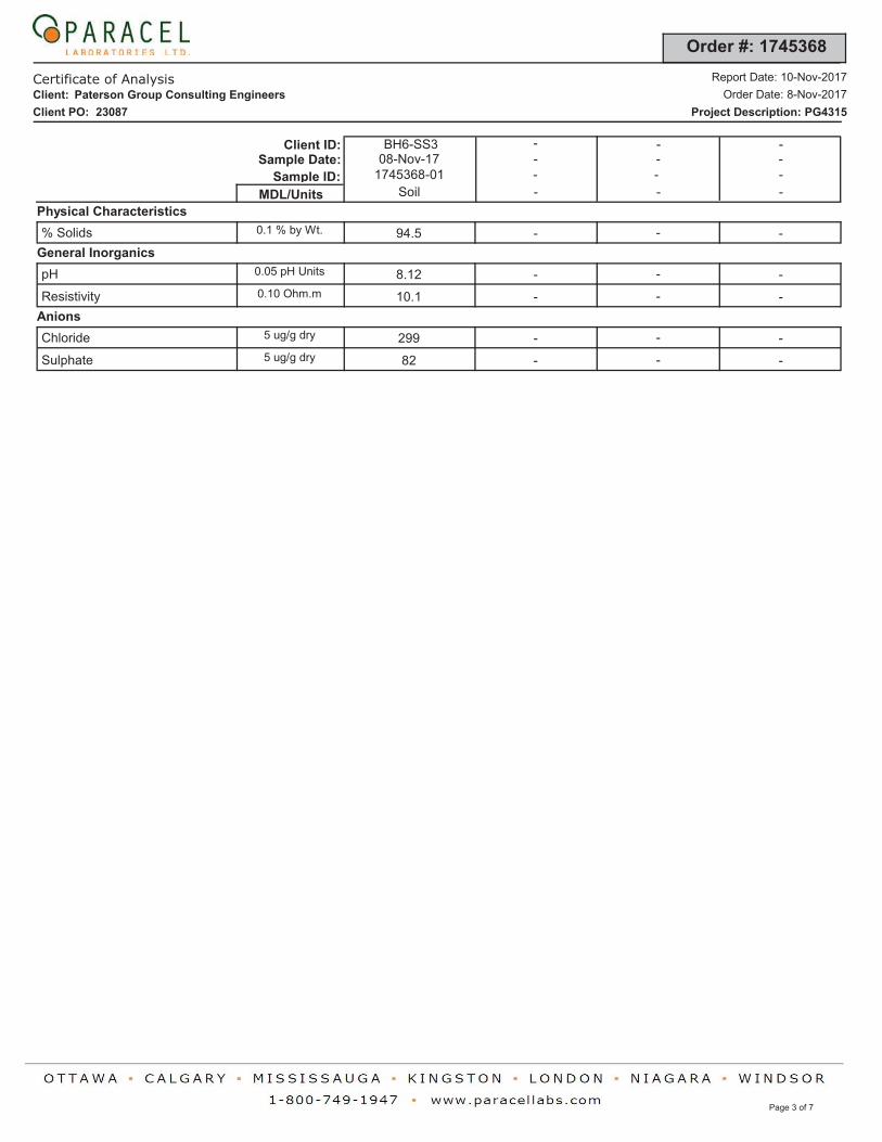
3.4 Analytical Testing
One (1) soil sample was submitted for analytical testing to assess the corrosion
potential for exposed ferrous metals and the potential of sulphate attacks against
subsurface concrete structures. The sample was submitted to determine the
concentration of sulphate and chloride, the resistivity and the pH of the sample. The
results are presented in Appendix 1 and are discussed further in Subsection 6.7.
Report: PG4315-1
December 11, 2017 Page 3

patersongroup Geotechnical InvestigationOttawa Kingston North Bay Proposed Building Expansion
4837 Albion Road - Ottawa
4.0 Observations
4.1 Surface Conditions
Currently, the subject site is occupied by a two storey building with a walk-out
basement and horse track, as well as access lanes, parking and landscaped areas.
The ground surface at the subject site is relatively flat within the parking area and
gradually slopes down eastward towards the horse track within the grass/treed area.
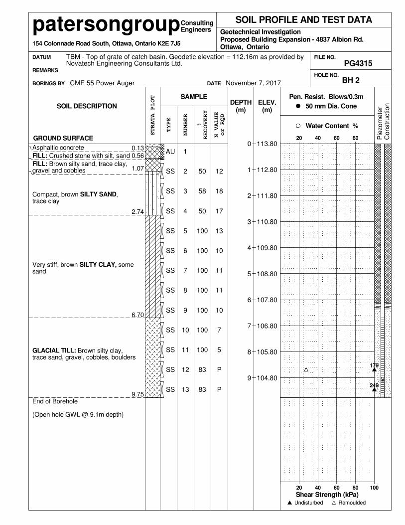
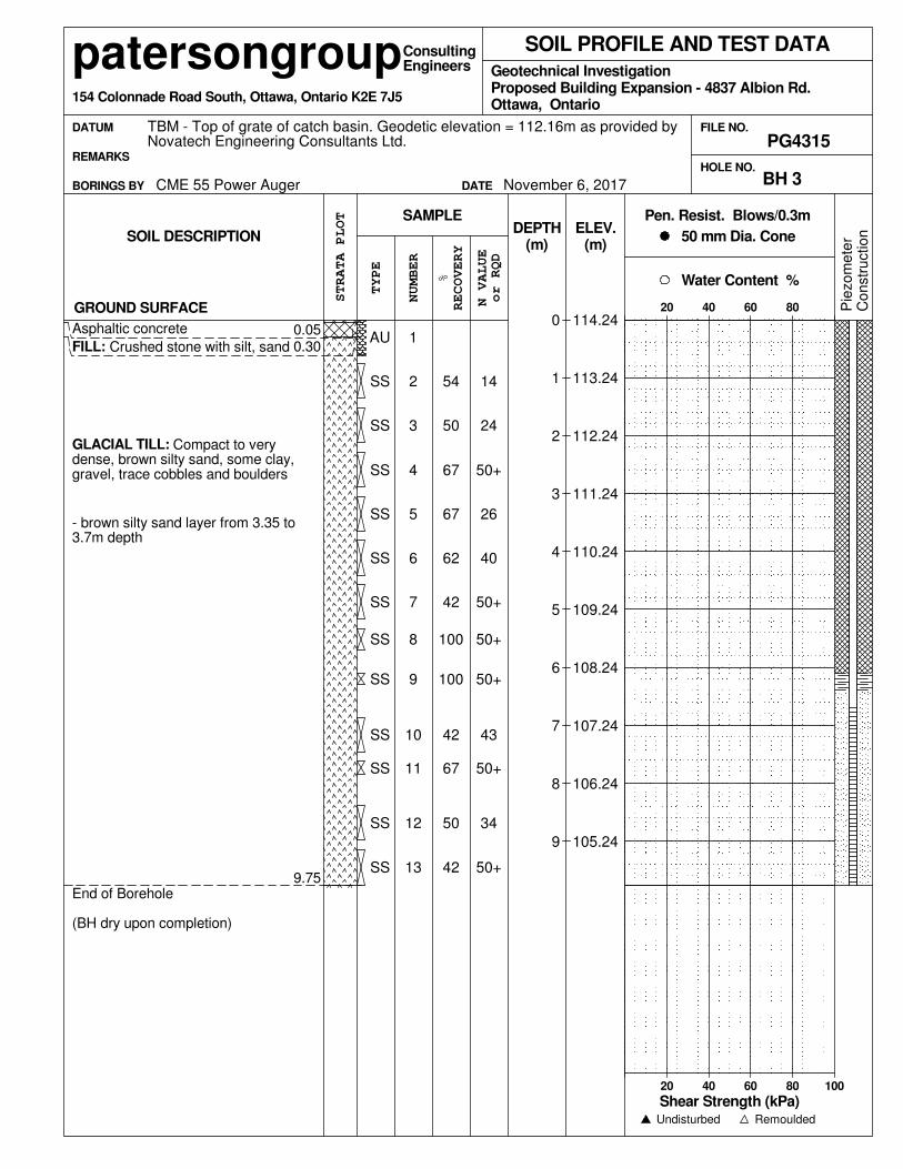
4.2 Subsurface Profile
Generally, the subsurface profile at the borehole locations consists of a thin layer of
topsoil or asphalt underlain by a crushed stone fill material with silty sand. The above
noted material is primarily underlain by a very dense to compact glacial till comprised
of a silty sand matrix with varying amounts of gravel, cobbles and boulders. A hard to
very stiff brown silty clay with occasional silty sand seams was observed overlying the
above noted glacial till in BH 2-17 and BH 5-17. A compact silty sand was encountered
below the above noted asphalt and fill material in BH 4-17. Practical refusal to augering
was observed at a depth of 7.6 and 9.5 m at BH 7-17 and BH 9-17, respectively, while
practical refusal to DCPT was observed at depths of 11.1 and 9.6 m at BH 5-17 and BH
11-17, respectively. Specific details of the soil profile at borehole locations are
presented on the Soil Profile and Test Data sheets in Appendix 1.
Based on available geological mapping, the subject site is located in an area where
bedrock is comprised of dolomite of the Oxford Formation with an overburden drift
thickness of 15 to 25 m depth.
4.3 Groundwater
Based on field observations, such as, moisture levels and colour of the recovered soil
samples, the long-term groundwater table can be expected at a depth greater than 7 m
below existing ground surface. It should be noted that groundwater levels are subject
to seasonal fluctuations and therefore could vary during the time of construction.
Report: PG4315-1
December 11, 2017 Page 4
patersongroup Geotechnical InvestigationOttawa Kingston North Bay Proposed Building Expansion
4837 Albion Road - Ottawa
5.0 Discussion
5.1 Geotechnical Assessment
From a geotechnical perspective, the subject site is adequate for the proposed building
expansion. It is expected that the proposed building can be founded by conventional
shallow foundations provided the bearing resistance values are sufficient to handle the
design building loads. Alternatively, a raft foundation or end bearing piled foundation
should be considered for the proposed building.
The above and other considerations are discussed in the following sections.
5.2 Site Grading and Preparation
Stripping Depth
Topsoil and deleterious fill, such as those containing organic materials, should be
stripped from under any buildings, paved areas, pipe bedding and other settlement
sensitive structures.
Fill Placement
Fill used for grading beneath the building structures should consist, unless otherwise
specified, of clean imported granular fill, such as Ontario Provincial Standard
Specifications (OPSS) Granular A or Granular B Type II. This material should be tested
and approved prior to delivery to the site. The fill should be placed in lifts no greater
than 300 mm thick and compacted using suitable compaction equipment for the lift
thickness. Fill placed beneath the building areas should be compacted to at least 98%
of the standard proctor maximum dry density (SPMDD)
Non-specified existing fill along with site-excavated soil can be used as general
landscaping fill where settlement of the ground surface is of minor concern. These
materials should be spread in thin lifts and at least compacted by the tracks of the
spreading equipment to minimize voids. Site excavated, brown silty clay under dry
conditions and above freezing temperatures and approved by the geotechnical
consultant at the time of placement can be used to build up the subgrade level for areas
to be paved. The brown silty clay should be placed in maximum 300 mm loose lifts and
compacted to a minimum density of 95% of its SPMDD.
Report: PG4315-1
December 11, 2017 Page 5

patersongroup Geotechnical InvestigationOttawa Kingston North Bay Proposed Building Expansion
4837 Albion Road - Ottawa
Non-specified existing fill and site-excavated soils are not suitable for use as backfill
against foundation walls unless a composite drainage blanket connected to a perimeter
drainage system is provided.
5.3 Foundation Design
Conventional Shallow Foundation
Footings placed on an undisturbed, dense glacial till, very stiff silty clay and/or dense
sand bearing surface can be designed using a bearing resistance value at serviceability
limit states (SLS) of 200 kPa and a factored bearing resistance value at ultimate limit
states (ULS) of 300 kPa.
Footings designed using the above-noted bearing resistance value at SLS will be
subjected to potential post-construction total and differential settlements of 25 and
20 mm, respectively.
An undisturbed soil bearing surface consists of a surface from which all topsoil and
deleterious materials, such as loose, frozen or disturbed soil, whether in situ or not,
have been removed, in the dry, prior to the placement of concrete for footings.
The bearing medium under footing-supported structures is required to be provided with
adequate lateral support with respect to excavations and different foundation levels.
Adequate lateral support is provided to a soil bearing medium when a plane extending
horizontally and vertically from the footing perimeter at a minimum of 1.5H:1V, passing
through in situ soil or engineered fill of equal or higher capacity as the soil.
Raft Foundation
Based on the expected loads of the proposed structure, it is anticipated that a raft
foundation will be required to found the multi-storey portions of the proposed structure.
For our design calculations, one basement level was assumed. It is expected that the
excavation will extend between 3 to 4 m below existing ground surface. The maximum
SLS contact pressure can be taken to be 350 kPa. It should be noted that the weight
of the raft slab and everything above has to be included when designing with this value.
The loading conditions for the contact pressure are based on sustained loads, that are
generally taken to be 100% Dead Load and 50% Live Load.
Report: PG4315-1
December 11, 2017 Page 6
patersongroup Geotechnical InvestigationOttawa Kingston North Bay Proposed Building Expansion
4837 Albion Road - Ottawa
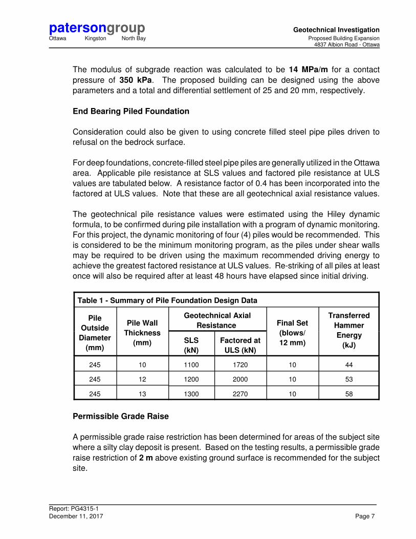
The modulus of subgrade reaction was calculated to be 14 MPa/m for a contact
pressure of 350 kPa. The proposed building can be designed using the above
parameters and a total and differential settlement of 25 and 20 mm, respectively.
End Bearing Piled Foundation
Consideration could also be given to using concrete filled steel pipe piles driven to
refusal on the bedrock surface.
For deep foundations, concrete-filled steel pipe piles are generally utilized in the Ottawa
area. Applicable pile resistance at SLS values and factored pile resistance at ULS
values are tabulated below. A resistance factor of 0.4 has been incorporated into the
factored at ULS values. Note that these are all geotechnical axial resistance values.
The geotechnical pile resistance values were estimated using the Hiley dynamic
formula, to be confirmed during pile installation with a program of dynamic monitoring.
For this project, the dynamic monitoring of four (4) piles would be recommended. This
is considered to be the minimum monitoring program, as the piles under shear walls
may be required to be driven using the maximum recommended driving energy to
achieve the greatest factored resistance at ULS values. Re-striking of all piles at least
once will also be required after at least 48 hours have elapsed since initial driving.
Table 1 - Summary of Pile Foundation Design Data
Pile
Outside
Diameter
(mm)
Pile Wall
Thickness
(mm)
Geotechnical Axial
Resistance Final Set
(blows/
12 mm)
Transferred
Hammer
Energy
(kJ)SLS
(kN)
Factored at
ULS (kN)
245 10 1100 1720 10 44
245 12 1200 2000 10 53
245 13 1300 2270 10 58
Permissible Grade Raise
A permissible grade raise restriction has been determined for areas of the subject site
where a silty clay deposit is present. Based on the testing results, a permissible grade
raise restriction of 2 m above existing ground surface is recommended for the subject
site.
Report: PG4315-1
December 11, 2017 Page 7
patersongroup Geotechnical InvestigationOttawa Kingston North Bay Proposed Building Expansion
4837 Albion Road - Ottawa
5.4 Design for Earthquakes
The site class for seismic site response can be taken as Class D for the foundations
considered at this site. A higher seismic site class, such as Class C, may be applicable
for foundation design. However, the higher seismic site class has to be confirmed by
site specific seismic shear wave velocity testing. The soils underlying the subject site
are not susceptible to liquefaction. Refer to the latest revision of the 2012 Ontario
Building Code for a full discussion of the earthquake design requirements.
5.5 Basement Floor Slab
With the removal of topsoil and deleterious fill, such as those containing organic
materials, within the footprint of the proposed building expansion, the native soil surface
will be considered to be an acceptable subgrade surface on which to commence
backfilling for floor slab construction. Any soft areas should be removed and backfilled
with appropriate backfill material. OPSS Granular A or Granular B Type II, with a
maximum particle size of 50 mm, are recommended for backfilling below the floor slab.
All backfill materials within the footprint of the proposed building should be placed in
maximum 200 mm thick loose layers and compacted to at least 98% of its SPMDD. It
is recommended that the upper 200 mm of sub-floor fill consist of 19 mm clear crushed
stone.
5.6 Basement Wall
The conditions can be well-represented by assuming the retained soil consists of a
material with an angle of internal friction of 30 degrees and a dry unit weight of
20 kN/m3. Undrained conditions are anticipated (i.e. below the groundwater level).
Therefore, the applicable effective unit weight of the retained soil can be taken as
13 kN/m3, where applicable. A hydrostatic pressure should be added to the total static
earth pressure when using the effective unit weight.
Two distinct conditions, static and seismic, should be reviewed for design calculations.
The parameters for design calculations for the two conditions are presented below.
Lateral Earth Pressures
The static horizontal earth pressure (po) can be calculated using a triangular earth
pressure distribution equal to Ko·γ·H where:
Ko = at-rest earth pressure coefficient of the applicable retained soil, 0.5
Report: PG4315-1
December 11, 2017 Page 8
patersongroup Geotechnical InvestigationOttawa Kingston North Bay Proposed Building Expansion
4837 Albion Road - Ottawa
γ = unit weight of the applicable retained soil (kN/m3)
H = height of the wall (m)
An additional pressure having a magnitude equal to Ko·q and acting on the entire height
of the wall should be added to the above diagram for any surcharge loading, q (kPa),
that may be placed at ground surface adjacent to the wall. The surcharge pressure will
only be applicable for static analyses and should not be used in conjunction with the
seismic loading case.
Actual earth pressures could be higher than the “at-rest” case if care is not exercised
during the compaction of the backfill materials to maintain a minimum separation of
0.3 m from the walls with the compaction equipment.
Seismic Earth Pressures
The total seismic force (PAE) includes both the earth force component (Po) and the
seismic component (ΔPAE). The seismic earth force (ΔPAE) can be calculated using
0.375·ac·γ·H2/g where:
ac = (1.45-amax/g)amax
γ = unit weight of fill of the applicable retained soil (kN/m3)
H = height of the wall (m)
g = gravity, 9.81 m/s2
The peak ground acceleration, (amax), for the Ottawa area is 0.32g according to
OBC 2012. Note that the vertical seismic coefficient is assumed to be zero.
The earth force component (Po) under seismic conditions can be calculated using
Po = 0.5 Ko γ H2, where Ko = 0.5 for the soil conditions noted above.
The total earth force (PAE) is considered to act at a height, h (m), from the base of the
wall, where:
h = {Po·(H/3)+ΔPAE·(0.6·H)}/PAE
The earth forces calculated are unfactored. For the ULS case, the earth loads should
be factored as live loads, as per OBC 2012.
Report: PG4315-1
December 11, 2017 Page 9
patersongroup Geotechnical InvestigationOttawa Kingston North Bay Proposed Building Expansion
4837 Albion Road - Ottawa
5.7 Pavement Structure
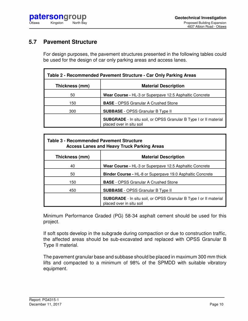
For design purposes, the pavement structures presented in the following tables could
be used for the design of car only parking areas and access lanes.
Table 2 - Recommended Pavement Structure - Car Only Parking Areas
Thickness (mm) Material Description
50 Wear Course - HL-3 or Superpave 12.5 Asphaltic Concrete
150 BASE - OPSS Granular A Crushed Stone
300 SUBBASE - OPSS Granular B Type II
SUBGRADE - In situ soil, or OPSS Granular B Type I or II material
placed over in situ soil
Table 3 - Recommended Pavement Structure
Access Lanes and Heavy Truck Parking Areas
Thickness (mm) Material Description
40 Wear Course - HL-3 or Superpave 12.5 Asphaltic Concrete
50 Binder Course - HL-8 or Superpave 19.0 Asphaltic Concrete
150 BASE - OPSS Granular A Crushed Stone
450 SUBBASE - OPSS Granular B Type II
SUBGRADE - In situ soil, or OPSS Granular B Type I or II material
placed over in situ soil
Minimum Performance Graded (PG) 58-34 asphalt cement should be used for this
project.
If soft spots develop in the subgrade during compaction or due to construction traffic,
the affected areas should be sub-excavated and replaced with OPSS Granular B
Type II material.
The pavement granular base and subbase should be placed in maximum 300 mm thick
lifts and compacted to a minimum of 98% of the SPMDD with suitable vibratory
equipment.
Report: PG4315-1
December 11, 2017 Page 10
patersongroup Geotechnical InvestigationOttawa Kingston North Bay Proposed Building Expansion
4837 Albion Road - Ottawa
6.0 Design and Construction Precautions
6.1 Foundation Drainage and Backfill
It is recommended that a perimeter foundation drainage system be provided for the
proposed building expansion and connected to the existing system. The system should
consist of a 150 mm diameter perforated corrugated plastic pipe, surrounded on all
sides by 150 mm of 19 mm clear crushed stone, placed at the footing level around the
exterior perimeter of the structures. The pipe should have a positive outlet, such as a
gravity connection to the storm sewer.
Backfill against the exterior sides of the foundation walls should consist of free-draining
non frost susceptible granular materials. The greater part of the site excavated
materials will be frost susceptible and, as such, are not recommended for re-use as
backfill against the foundation walls, unless used in conjunction with a drainage
geocomposite, such as Delta Drain 6000, connected to the perimeter foundation
drainage system. Imported granular materials, such as clean sand or OPSS Granular B
Type I granular material, should otherwise be used for this purpose.
6.2 Protection of Footings Against Frost Action
Perimeter footings of heated structures are recommended to be protected against the
deleterious effects of frost action. A minimum of 1.5 m of soil cover alone, or a
combination of soil cover and foundation insulation should be provided.
Exterior unheated footings, such as those for isolated exterior piers, are more prone to
deleterious movement associated with frost action than the exterior walls of the
structure proper and require additional protection, such as soil cover of 2.1 m or a
combination of soil cover and foundation insulation.
6.3 Excavation Side Slopes
Temporary Side Slopes
The temporary excavation side slopes anticipated should either be excavated to
acceptable slopes or retained by shoring systems from the beginning of the excavation
until the structure is backfilled.
Report: PG4315-1
December 11, 2017 Page 11

patersongroup Geotechnical InvestigationOttawa Kingston North Bay Proposed Building Expansion
4837 Albion Road - Ottawa
The excavation side slopes above the groundwater level extending to a maximum depth
of 3 m should be cut back at 1H:1V or flatter. The flatter slope is required for
excavation below groundwater level. The subsurface soil is considered to be mainly a
Type 2 and 3 soil according to the Occupational Health and Safety Act and Regulations
for Construction Projects. Excavated soil should not be stockpiled directly at the top of
excavations and heavy equipment should maintain safe working distance from the
excavation sides.
Slopes in excess of 3 m in height should be periodically inspected by the geotechnical
consultant in order to detect if the slopes are exhibiting signs of distress.
It is recommended that a trench box be used at all times to protect personnel working
in trenches with steep or vertical sides. It is expected that services will be installed by
“cut and cover” methods and excavations will not be left open for extended periods of
time.
6.4 Pipe Bedding and Backfill
Bedding and backfill materials should be in accordance with the most recent Material
Specifications & Standard Detail Drawings from the Department of Public Works and
Services, Infrastructure Services Branch of the City of Ottawa.
A minimum of 150 mm of OPSS Granular A should be placed for bedding for sewer or
water pipes when placed on soil subgrade. The bedding should extend to the spring
line of the pipe. Cover material, from the spring line to a minimum of 300 mm above
the obvert of the pipe should consist of OPSS Granular A (concrete or PSM PVC pipes)
or sand (concrete pipe). The bedding and cover materials should be placed in
maximum 225 mm thick lifts and compacted to 95% of the material’s SPMDD.
Where hard surface areas are considered above the trench backfill, the trench backfill
material within the frost zone (about 1.8 m below finished grade) should match the soils
exposed at the trench walls to reduce the potential differential frost heaving. The trench
backfill should be placed in maximum 300 mm thick loose lifts and compacted to a
minimum of 95% of the SPMDD.
Report: PG4315-1
December 11, 2017 Page 12
patersongroup Geotechnical InvestigationOttawa Kingston North Bay Proposed Building Expansion
4837 Albion Road - Ottawa
6.5 Groundwater Control
It is anticipated that groundwater infiltration into the excavations should be low and
controllable using open sumps. Pumping from open sumps should be sufficient to
control the groundwater influx through the sides of the shallow excavation. The
contractor should be prepared to direct water away from all bearing surfaces and
subgrades, regardless of the source, to prevent disturbance to the founding medium.
Groundwater Control for Building Construction
A temporary Ministry of the Environment and Climate Change (MOECC) permit to take
water (PTTW) is not anticipated to be required based on current building details.
However, if more than 400,000 L/day of ground and/or surface water is to be pumped
during the construction phase. A minimum 4 to 5 months should be allowed for
completion of the PTTW application package and issuance of the permit by the
MOECC.
Also, if typical ground or surface water volumes are between 50,000 to 400,000 L/day,
it is required to register on the Environmental Activity and Sector Registry (EASR). A
minimum of two to four weeks should be allotted for completion of the EASR
registration and the Water Taking and Discharge Plan to be prepared by a Qualified
Person as stipulated under O.Reg. 63/16. If a project qualifies for a PTTW based upon
anticipated conditions, an EASR will not be allowed as a temporary dewatering
measure while awaiting the MOECC review of the PTTW application.
Impacts on Neighbouring Structures
Based on the existing groundwater level, a groundwater lowering will not take place due
to construction of the proposed building expansion. It should be noted that no issues
are expected with respect to groundwater lowering that would cause long term damage
to adjacent structures surrounding the proposed building.
Report: PG4315-1
December 11, 2017 Page 13

patersongroup Geotechnical InvestigationOttawa Kingston North Bay Proposed Building Expansion
4837 Albion Road - Ottawa
6.6 Winter Construction
Precautions must be taken if winter construction is considered for this project. The
subsoil conditions at this site consist of frost susceptible materials. In the presence of
water and freezing conditions, ice could form within the soil mass. Heaving and
settlement upon thawing could occur.
In the event of construction during below zero temperatures, the founding stratum
should be protected from freezing temperatures by the installation of straw, propane
heaters and tarpaulins or other suitable means. The base of the excavations should
be insulated from sub-zero temperatures immediately upon exposure and until such
time as heat is adequately supplied to the building and the footings are protected with
sufficient soil cover to prevent freezing at founding level.
Trench excavations and pavement construction are difficult activities to complete during
freezing conditions without introducing frost in the subgrade or in the excavation walls
and bottoms. Precautions should be considered if such activities are to be completed
during freezing conditions. Additional information could be provided, if required.
6.7 Corrosion Potential and Sulphate
The results of analytical testing show that the sulphate content is less than 0.1%. This
result is indicative that Type 10 Portland cement (normal cement) would be appropriate
for this site. The chloride content and the pH of the samples indicate that they are not
significant factors in creating a corrosive environment for exposed ferrous metals at this
site, whereas the resistivity is indicative of a low corrosive environment.
Report: PG4315-1
December 11, 2017 Page 14
patersongroup Geotechnical InvestigationOttawa Kingston North Bay Proposed Building Expansion
4837 Albion Road - Ottawa
7.0 Recommendations
A materials testing and observation services program is a requirement for the provided
foundation design data to be applicable. The following aspects of the program should
be performed by the geotechnical consultant:
‘ Observation of all bearing surfaces prior to the placement of concrete.
‘ Sampling and testing of the concrete and fill materials used.
‘ Periodic observation of the condition of unsupported excavation side slopes in
excess of 3 m in height, if applicable.
‘ Observation of all subgrades prior to backfilling.
‘ Field density tests to determine the level of compaction achieved.
‘ Sampling and testing of the bituminous concrete including mix design reviews.
A report confirming that these works have been conducted in general accordance with
our recommendations could be issued, upon request, following the completion of a
satisfactory materials testing and observation program by the geotechnical consultant.
Report: PG4315-1
December 11, 2017 Page 15
patersongroup Geotechnical InvestigationOttawa Kingston North Bay Proposed Building Expansion
4837 Albion Road - Ottawa
8.0 Statement of Limitations
The recommendations provided in this report are in accordance with our present
understanding of the project.
A geotechnical investigation is a limited sampling of a site. The recommendations are
based on information gathered at the specific test locations and can only be
extrapolated to an undefined limited area around the test locations. Should any
conditions at the site be encountered which differ from those at the test locations,
Paterson requests notification immediately in order to permit reassessment of the
recommendations.
The present report applies only to the project described in this document. Use of this
report for purposes other than those described herein or by person(s) other than Hard
Rock Ottawa, The Stirling Group or their agent(s) is not authorized without review by
Paterson Group for the applicability of our recommendations to the altered use of the
report.
Paterson Group Inc. Dec. 12-2017
Nicholas Zulinski, P.Geo. David J. Gilbert, P.Eng.
Report Distribution:
‘ Hard Rock Ottawa (3 copies)
‘ Paterson Group (1 copy)
Report: PG4315-1
December 11, 2017 Page 16

APPENDIX 1
SOIL PROFILE AND TEST DATA SHEETS
SYMBOLS AND TERMS
ANALYTICAL TESTING RESULTS

SS
SS
9.75
0.59
SS
SS
SS
SS
SS
SS
SS
SS
SS
(m)
0.11
GROUND SURFACE0
1
2
3
4
5
6
7
8
9
NUMBER
HOLE NO.
AUAsphaltic concrete
31
SS
71
41
50+
50+
37
50
21
23
42
50+48
24
23
End of Borehole
(BH dry upon completion)
- compact, brown silty sand layerfrom 4.5 to 6.0m depth
GLACIAL TILL: Compact to verydense, brown silty sand, somegravel, cobbles, trace boulders
FILL: Brown silty sand, some gravel,trace clay, cobbles, boulders
50+
2
13
12
11
10
9
8
7
6
5
583
1
50
58
75
58
67
62
58
58
4
Remoulded
patersongroupGeotechnical Investigation
BORINGS BY
Ottawa, Ontario
STRATA PLOT
DEPTH50 mm Dia. Cone
SAMPLE
RECOVERY
Co
nstr
uctio
nP
iezo
me
ter(m)
Consulting
Undisturbed
Pen. Resist. Blows/0.3m
CME 55 Power Auger BH 1
20 40 60 80 100
REMARKS
DATUM
20 40 60 80
Engineers
FILE NO.
Proposed Building Expansion - 4837 Albion Rd.
SOIL DESCRIPTION
TBM - Top of grate of catch basin. Geodetic elevation = 112.16m as provided byNovatech Engineering Consultants Ltd.
or RQD
Shear Strength (kPa)
SOIL PROFILE AND TEST DATA
Water Content %
154 Colonnade Road South, Ottawa, Ontario K2E 7J5
113.47
112.47
111.47
110.47
109.47
108.47
107.47
106.47
105.47
104.47
November 7, 2017DATE
TYPE
N VALUE
%
PG4315
ELEV.
12
18
13
10
11
11
10
7
5
P
17
100
249
179
GROUND SURFACE
FILL: Brown silty sand, trace clay,gravel and cobbles
Asphaltic concrete
Compact, brown SILTY SAND,trace clay
Very stiff, brown SILTY CLAY, somesand
GLACIAL TILL: Brown silty clay,trace sand, gravel, cobbles, boulders
End of Borehole
(Open hole GWL @ 9.1m depth)
50
FILL: Crushed stone with silt, sand
9
P
SS
SS
SS
SS
SS
SS
AU
13
12
SS
10SS
8
7
6
5
4
3
2
1
83
83
10011
249
58
50
100
100
100
SS 100
100
9.75
6.70
2.74
1.07
0.560.13
SS
SS
SS
patersongroupProposed Building Expansion - 4837 Albion Rd.Geotechnical Investigation
Remoulded
179
SAMPLE
BORINGS BY
Ottawa, Ontario
Co
nstr
uctio
nP
iezo
me
ter(m)
Consulting
Undisturbed
Pen. Resist. Blows/0.3m
BH 2
FILE NO.
RECOVERY
REMARKS
DATUM
20 40 60 80
Engineers
CME 55 Power Auger
Shear Strength (kPa)
ELEV.
%
N VALUE
SOIL PROFILE AND TEST DATA
(m)
0
1
2
3
4
5
6
7
8
9
NUMBER
HOLE NO.
TYPE
November 7, 2017
STRATA PLOT
DEPTH50 mm Dia. Cone
Water Content %
20 40 60 80 100
PG4315
113.80
112.80
111.80
110.80
109.80
108.80
107.80
106.80
105.80
104.80
SOIL DESCRIPTION
TBM - Top of grate of catch basin. Geodetic elevation = 112.16m as provided byNovatech Engineering Consultants Ltd.
or RQD
154 Colonnade Road South, Ottawa, Ontario K2E 7J5
DATE
SS
9.75
0.30
SS
SS
SS
50+
40
26
50+
24
14
(m)
0.05
GROUND SURFACE0
1
2
3
4
5
6
7
8
9
NUMBER
HOLE NO.
50+
62
3
2
1
42
50
67
42
100
5
42
6
67
67
50
54
50+
34
50+
43
50+
100
SS
End of Borehole
(BH dry upon completion)
- brown silty sand layer from 3.35 to3.7m depth
GLACIAL TILL: Compact to verydense, brown silty sand, some clay,gravel, trace cobbles and boulders
FILL: Crushed stone with silt, sand
Asphaltic concrete
SS
SS
SS
SS
4SS
SS
AU
13
12
11
10
9
8
7
SS
Remoulded
patersongroupGeotechnical Investigation
BORINGS BY
Ottawa, Ontario
STRATA PLOT
DEPTH50 mm Dia. Cone
SAMPLE
RECOVERY
Co
nstr
uctio
nP
iezo
me
ter(m)
Consulting
Undisturbed
Pen. Resist. Blows/0.3m
CME 55 Power Auger BH 3
20 40 60 80 100
REMARKS
DATUM
20 40 60 80
Engineers
FILE NO.
Proposed Building Expansion - 4837 Albion Rd.
SOIL DESCRIPTION
TBM - Top of grate of catch basin. Geodetic elevation = 112.16m as provided byNovatech Engineering Consultants Ltd.
or RQD
Shear Strength (kPa)
SOIL PROFILE AND TEST DATA
Water Content %
154 Colonnade Road South, Ottawa, Ontario K2E 7J5
114.24
113.24
112.24
111.24
110.24
109.24
108.24
107.24
106.24
105.24
November 6, 2017DATE
TYPE
N VALUE
%
PG4315
ELEV.
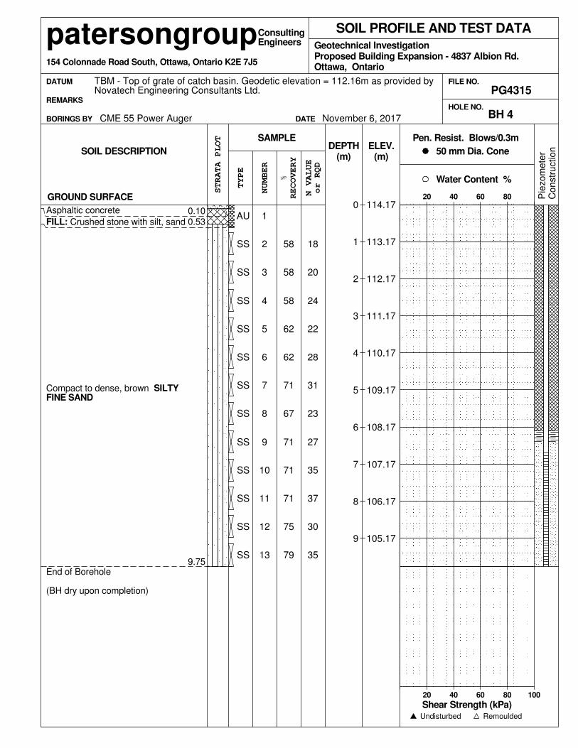
SS9.75
(m)
0.10
SS
SS
SS
SS
SS
SS
SS
SS
SS
0.53
GROUND SURFACE0
1
2
3
4
5
6
7
8
9
NUMBER
HOLE NO.
Asphaltic concreteAU
22
SS 58
58
35
30
37
35
27
23
62
2862
24
20
18
End of Borehole
(BH dry upon completion)
Compact to dense, brown SILTYFINE SAND
FILL: Crushed stone with silt, sand
31
3
13
12
11
10
9
8
7
6
584
SS 2
1
79
75
71
71
71
67
71
5
Water Content %
Remoulded
patersongroupGeotechnical Investigation
BORINGS BY
Ottawa, Ontario
STRATA PLOT
DEPTH50 mm Dia. Cone
SAMPLE
RECOVERY
Co
nstr
uctio
nP
iezo
me
ter(m)
Consulting
Undisturbed
Pen. Resist. Blows/0.3m
CME 55 Power Auger BH 4
REMARKS
DATUM
20 40 60 80
Engineers
FILE NO.
Proposed Building Expansion - 4837 Albion Rd.
114.17
113.17
112.17
111.17
110.17
109.17
108.17
107.17
106.17
105.17
Shear Strength (kPa)
SOIL DESCRIPTION
154 Colonnade Road South, Ottawa, Ontario K2E 7J5
SOIL PROFILE AND TEST DATA
or RQD
TBM - Top of grate of catch basin. Geodetic elevation = 112.16m as provided byNovatech Engineering Consultants Ltd.
20 40 60 80 100
DATE
TYPE
N VALUE
%
November 6, 2017
ELEV.
PG4315
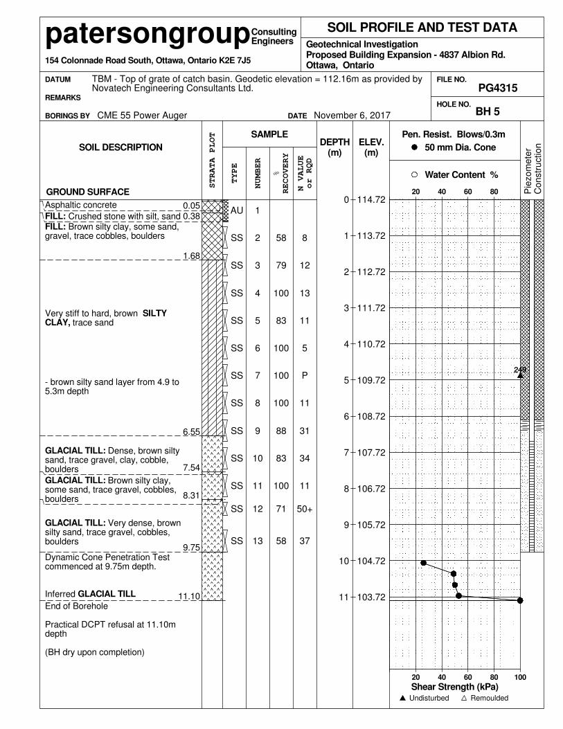
13
100
8
12
11
5
P
11
31
34
11
Very stiff to hard, brown SILTYCLAY, trace sand
249
FILL: Crushed stone with silt, sandFILL: Brown silty clay, some sand,gravel, trace cobbles, boulders
GROUND SURFACE
- brown silty sand layer from 4.9 to5.3m depth
Asphaltic concrete
GLACIAL TILL: Dense, brown siltysand, trace gravel, clay, cobble,boulders
GLACIAL TILL: Brown silty clay,some sand, trace gravel, cobbles,boulders
GLACIAL TILL: Very dense, brownsilty sand, trace gravel, cobbles,boulders
Dynamic Cone Penetration Testcommenced at 9.75m depth.
Inferred GLACIAL TILL
End of Borehole
Practical DCPT refusal at 11.10mdepth
(BH dry upon completion)
6SS
SS
SS
SS
SS
AU
13
12
11
10
9
7
SS
5
4
3
2
1
58
71
100
83
88
1008
11.10
37
58
79
100
83
SS
SS
9.75
8.31
7.54
6.55
1.68
0.380.05
SS
SS
SS
SS
50+
100
Geotechnical Investigation
Remoulded
patersongroup
SAMPLE
BORINGS BY
Ottawa, Ontario
Co
nstr
uctio
nP
iezo
me
ter(m)
Consulting
Undisturbed
Pen. Resist. Blows/0.3m
CME 55 Power Auger
Proposed Building Expansion - 4837 Albion Rd.
RECOVERY
REMARKS
DATUM
20 40 60 80
Engineers
FILE NO.
DEPTH
BH 5
ELEV.
%
N VALUE
TYPE
SOIL PROFILE AND TEST DATA
(m)
0
1
2
3
4
5
6
7
8
9
10
11
STRATA PLOT
HOLE NO.
Shear Strength (kPa)
249
NUMBER
114.72
113.72
112.72
111.72
110.72
109.72
108.72
107.72
106.72
105.72
104.72
103.72
50 mm Dia. Cone
Water Content %
20 40 60 80 100
DATE November 6, 2017
PG4315
SOIL DESCRIPTION
TBM - Top of grate of catch basin. Geodetic elevation = 112.16m as provided byNovatech Engineering Consultants Ltd.
or RQD
154 Colonnade Road South, Ottawa, Ontario K2E 7J5

SS
Pie
zo
me
ter
9.75
0.430.06
SSC
on
str
uctio
n
SS
SS
SS
SS
SS
SS
SS
SS
SS
AU
SS
DATUM
REMARKS
RECOVERY
BH 6
Pen. Resist. Blows/0.3m
RemouldedUndisturbed
Consulting
(m)
11
CME 55 Power Auger
23
13
26
28
23
22
31
50+
50+
14
42
2642
End of Borehole
(BH dry upon completion)
- compact, brown silty sand layerfrom 3.0 to 3.7m depth
GLACIAL TILL: Compact to dense,brown silty sand, some gravel,cobbles, trace clay, boulders
FILL: Crushed stone with silt, sand
Asphaltic concrete
GROUND SURFACE
28
50
Engineers
10
9
8
7
6
5
4
3
30
1
12 54
50
42
58
50
46
67
33
50
2
Water Content %
20 40 60 80 100
DATE November 7, 2017
DEPTH
114.20
113.20
112.20
111.20
110.20
109.20
108.20
107.20
106.20
105.20
SOIL DESCRIPTION
TBM - Top of grate of catch basin. Geodetic elevation = 112.16m as provided byNovatech Engineering Consultants Ltd.
or RQD
154 Colonnade Road South, Ottawa, Ontario K2E 7J5
PG4315
patersongroup
50 mm Dia. Cone
SAMPLE
BORINGS BY
Ottawa, Ontario
STRATA PLOT
FILE NO.
Geotechnical InvestigationProposed Building Expansion - 4837 Albion Rd.
Shear Strength (kPa)
ELEV.
%
N VALUE
20 40 60 80
SOIL PROFILE AND TEST DATA
(m)
0
1
2
3
4
5
6
7
8
9
NUMBER
HOLE NO.
TYPE
SS
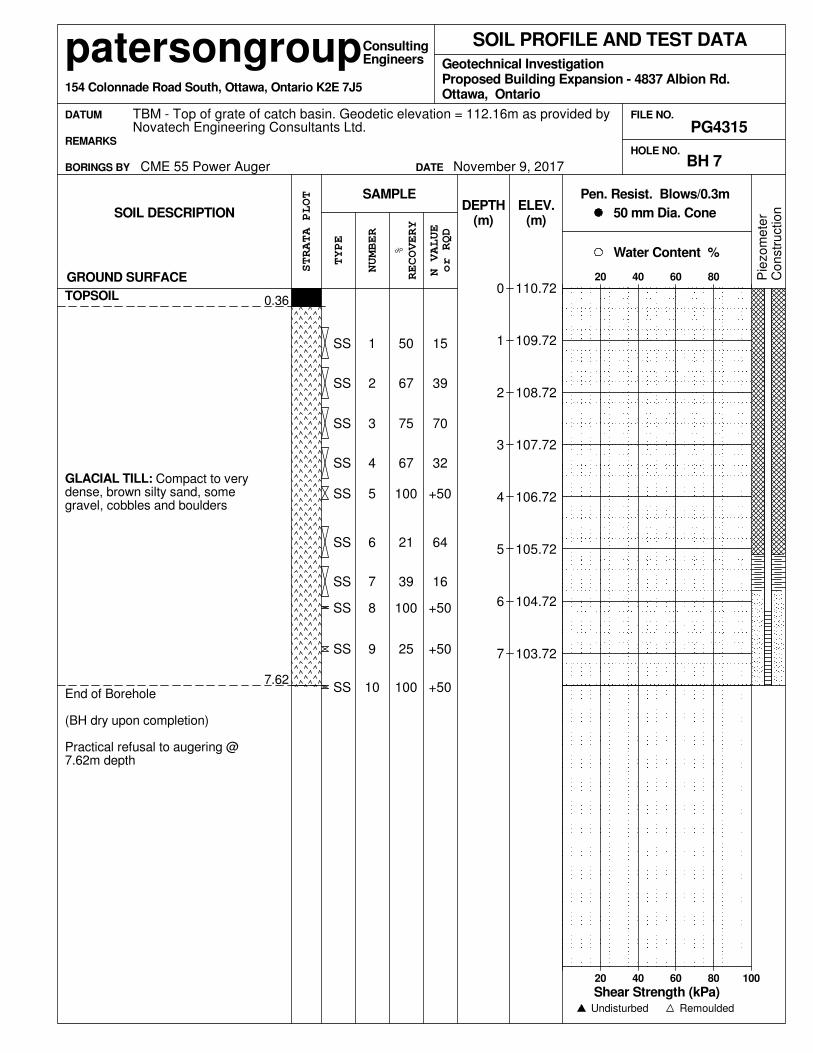
7.62
0.36
SS
SS
0
1
2
3
4
5
6
7
ELEV.
%
N VALUE
TYPE
SOIL PROFILE AND TEST DATA
GROUND SURFACE
TOPSOIL
HOLE NO.
SS
(m)
+50
67
75
67
50
+50
+50
+50SS
64
39
32
70
39
15
End of Borehole
(BH dry upon completion)
Practical refusal to augering @7.62m depth
GLACIAL TILL: Compact to verydense, brown silty sand, somegravel, cobbles and boulders
16
5SS
SS
SS
SS
SS
10
9
8
100
6 21
4
3
2
1
100
25
100
7
BORINGS BY
Ottawa, Ontario
NUMBER
Engineers
20 40 60 80
DATUM
REMARKS
RECOVERY
FILE NO.
Proposed Building Expansion - 4837 Albion Rd.Geotechnical Investigation
SAMPLE
patersongroup
BH 7
Remoulded
STRATA PLOT
November 9, 2017
PG4315
110.72
109.72
108.72
107.72
106.72
105.72
104.72
103.72
SOIL DESCRIPTION
Co
nstr
uctio
n
TBM - Top of grate of catch basin. Geodetic elevation = 112.16m as provided byNovatech Engineering Consultants Ltd.
DATE
or RQD
154 Colonnade Road South, Ottawa, Ontario K2E 7J5
Shear Strength (kPa)
CME 55 Power Auger
Pen. Resist. Blows/0.3mDEPTH
Undisturbed
Consulting
50 mm Dia. Cone
Pie
zo
me
ter
Water Content %
20 40 60 80 100
(m)
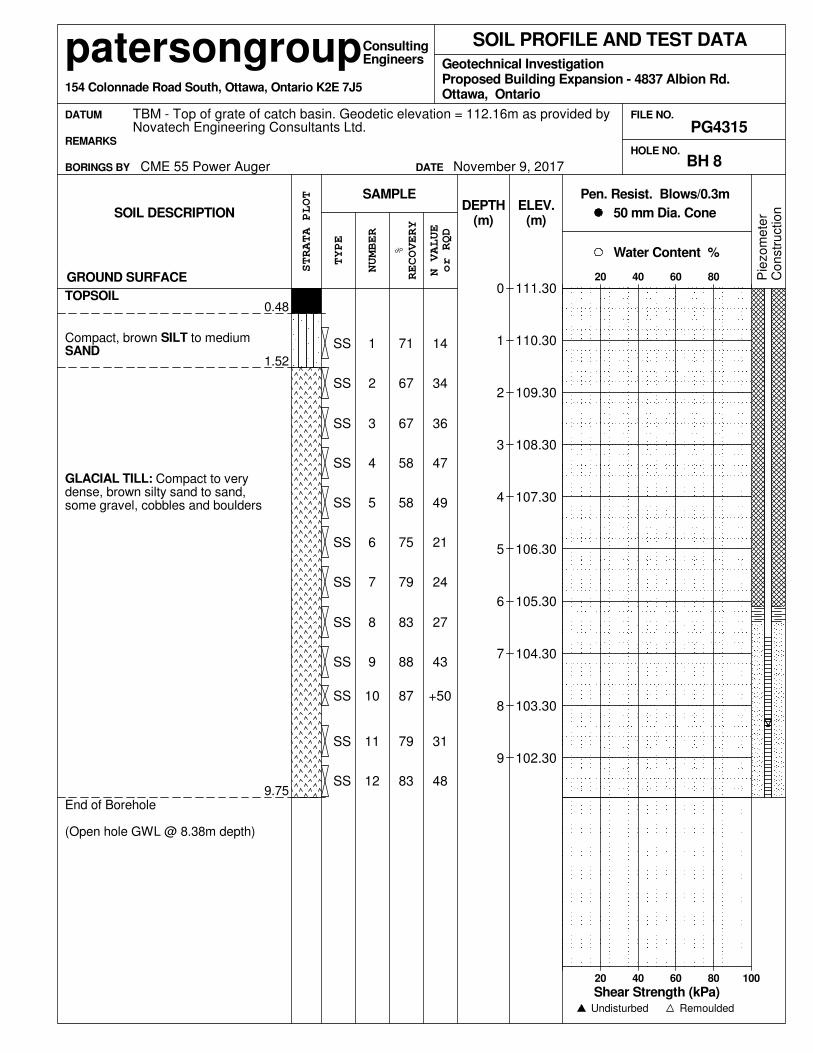
34
Compact, brown SILT to mediumSAND
GLACIAL TILL: Compact to verydense, brown silty sand to sand,some gravel, cobbles and boulders
End of Borehole
(Open hole GWL @ 8.38m depth)
27
14
GROUND SURFACE
36
47
49
21
24
+50
BH 8
Pen. Resist. Blows/0.3m
Undisturbed
Consulting
(m)
TOPSOIL
CME 55 Power Auger
Pie
zo
me
ter
Co
nstr
uctio
n
83
6
5
4
3
2
1
83
79
889
79
75
58
58
67
67
71
48
31
87
SS
43
9.75
1.52
0.48
SS
SS
SS
SS
7SS
8
SS
SS
SS
SS
SS
12
11
10
SS
BORINGS BY
patersongroup
SAMPLE
Ottawa, Ontario
STRATA PLOT
DEPTH
RECOVERY
REMARKS
DATUM
20 40 60 80
Engineers
FILE NO.
Proposed Building Expansion - 4837 Albion Rd.Geotechnical Investigation
Remoulded
(m)50 mm Dia. Cone
ELEV.
%
N VALUE
TYPE
SOIL PROFILE AND TEST DATA
0
1
2
3
4
5
6
7
8
9
NUMBER
HOLE NO.
111.30
110.30
109.30
108.30
107.30
106.30
105.30
104.30
103.30
102.30
Water Content %
20 40 60 80 100
DATE November 9, 2017
PG4315
Shear Strength (kPa)
SOIL DESCRIPTION
TBM - Top of grate of catch basin. Geodetic elevation = 112.16m as provided byNovatech Engineering Consultants Ltd.
or RQD
154 Colonnade Road South, Ottawa, Ontario K2E 7J5
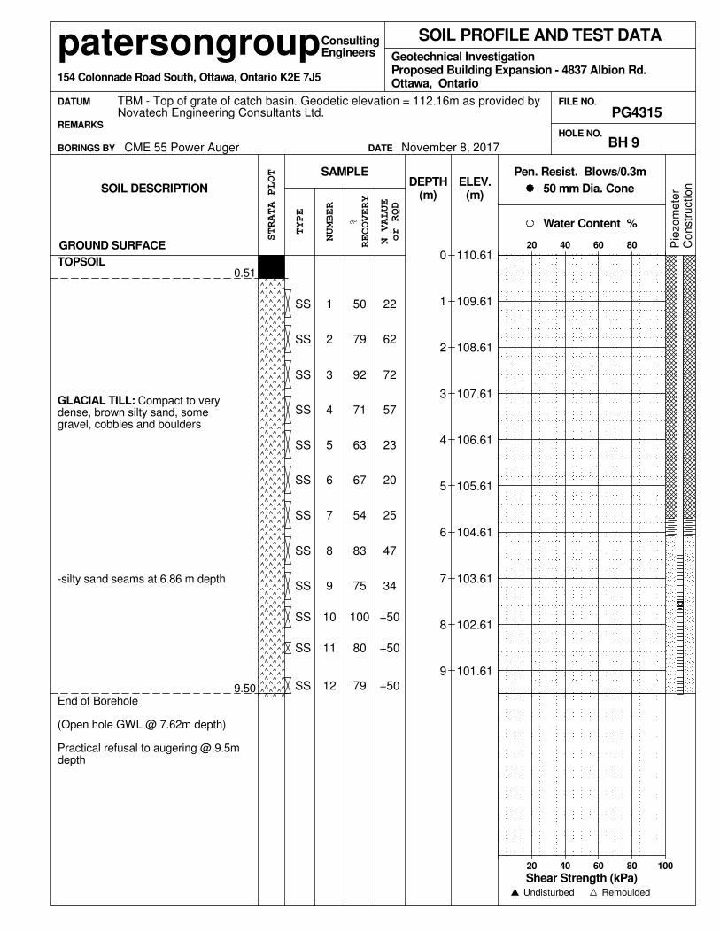
9.50
0.51
SS
SS
SS
SS
SS
SS
SS
SS
SOIL PROFILE AND TEST DATA
(m)
0
1
2
3
4
5
6
7
8
9
NUMBER
HOLE NO.
SS
GROUND SURFACE
TOPSOIL
23
92
79
50
+50
+50
+50
34
47
SS
2067
57
72
62
22
End of Borehole
(Open hole GWL @ 7.62m depth)
Practical refusal to augering @ 9.5mdepth
-silty sand seams at 6.86 m depth
GLACIAL TILL: Compact to verydense, brown silty sand, somegravel, cobbles and boulders
25
3
SS
12
11
10
9
8
7
6
714
63
2
1
79
80
100
75
83
54
SS
5
50 mm Dia. Cone
Remoulded
patersongroupGeotechnical Investigation
SAMPLE
BORINGS BY
Ottawa, Ontario
STRATA PLOT
DEPTH
RECOVERY
Co
nstr
uctio
nP
iezo
me
ter(m)
Consulting
Undisturbed
Pen. Resist. Blows/0.3m
CME 55 Power Auger BH 9
REMARKS
DATUM
20 40 60 80
Engineers
FILE NO.
Proposed Building Expansion - 4837 Albion Rd.
SOIL DESCRIPTION
TYPE
TBM - Top of grate of catch basin. Geodetic elevation = 112.16m as provided byNovatech Engineering Consultants Ltd. PG4315
or RQD
November 8, 2017
154 Colonnade Road South, Ottawa, Ontario K2E 7J5
110.61
109.61
108.61
107.61
106.61
105.61
104.61
103.61
102.61
101.61
N VALUE
% Water Content %
Shear Strength (kPa)20 40 60 80 100
DATE
ELEV.
9.75
SS
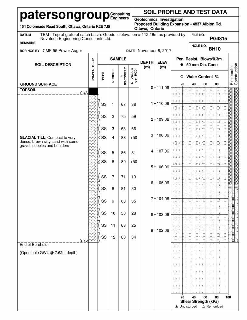
0.46
SS
SS
SS
SS
SS
SS
SS
SOIL PROFILE AND TEST DATA
(m)
0
1
2
3
4
5
6
7
8
9
NUMBER
HOLE NO.
SS
GROUND SURFACE
TOPSOIL
+50
SS
63
75
67
34
25
28
35
86
19
89
81
+50
66
59
38
End of Borehole
(Open hole GWL @ 7.62m depth)
GLACIAL TILL: Compact to verydense, brown silty sand with somegravel, cobbles and boulders
80
4
SS
SS
12
11
10
9
8
7
88
5
3
2
1
83
63
38
63
81
71
6
FILE NO.
Proposed Building Expansion - 4837 Albion Rd.
STRATA PLOT
DEPTH
Ottawa, Ontario
Water Content %
Engineers
TYPE
Geotechnical Investigation
Remoulded
DATUM
patersongroup
SAMPLE
BORINGS BY
111.06
110.06
109.06
108.06
107.06
106.06
105.06
104.06
103.06
102.06
SOIL DESCRIPTION
TBM - Top of grate of catch basin. Geodetic elevation = 112.16m as provided byNovatech Engineering Consultants Ltd.
Co
nstr
uctio
n
or RQD
154 Colonnade Road South, Ottawa, Ontario K2E 7J5
20 40 60 80
Shear Strength (kPa)
ELEV.
%
N VALUE
PG4315
50 mm Dia. Cone
REMARKS
DATE
RECOVERY
BH10November 8, 2017
Pie
zo
me
ter
Pen. Resist. Blows/0.3m
Undisturbed
Consulting
(m)
20 40 60 80 100
CME 55 Power Auger
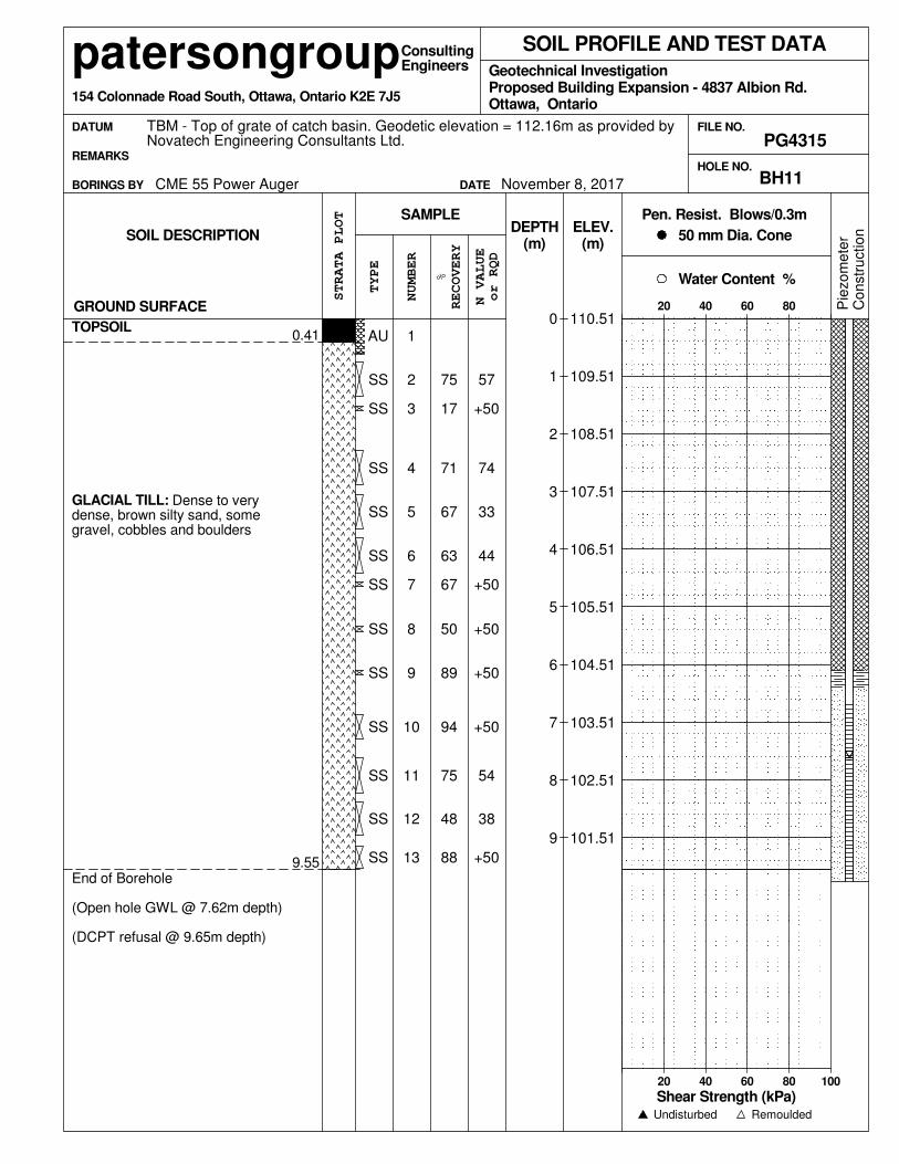
0.41
SS
9.55 SS
SS
SS
SS
SS
SS
SS
SS
SOIL PROFILE AND TEST DATA
GROUND SURFACE
(m)
0
1
2
3
4
5
6
7
8
9
NUMBER
HOLE NO.
TOPSOIL
SS
+50
67
71
17
75
+50
38
54
+50
SS
+5050
44
33
74
+50
57
End of Borehole
(Open hole GWL @ 7.62m depth)
(DCPT refusal @ 9.65m depth)
GLACIAL TILL: Dense to verydense, brown silty sand, somegravel, cobbles and boulders
+50
4
SS
AU
13
12
11
10
9
8
7
63
5
67
3
2
1
88
48
75
94
89
6
FILE NO.
STRATA PLOT
DEPTH50 mm Dia. Cone
Proposed Building Expansion - 4837 Albion Rd.
20 40 60 80 100
DATE
Geotechnical Investigation
Water Content %
Remoulded
SAMPLE
BORINGS BY
Ottawa, Ontario
20 40 60 80
patersongroup
Pie
zo
me
ter
Co
nstr
uctio
n
TBM - Top of grate of catch basin. Geodetic elevation = 112.16m as provided byNovatech Engineering Consultants Ltd.
or RQD
154 Colonnade Road South, Ottawa, Ontario K2E 7J5
Engineers
Shear Strength (kPa)
ELEV.
%
N VALUE
TYPE
Pen. Resist. Blows/0.3m
DATUM
November 8, 2017
REMARKS
RECOVERY
PG4315
BH11
Undisturbed
Consulting
(m)
110.51
109.51
108.51
107.51
106.51
105.51
104.51
103.51
102.51
101.51
SOIL DESCRIPTION
CME 55 Power Auger

SYMBOLS AND TERMS
SOIL DESCRIPTION Behavioural properties, such as structure and strength, take precedence over particle gradation in
describing soils. Terminology describing soil structure are as follows:
Desiccated - having visible signs of weathering by oxidation of clay
minerals, shrinkage cracks, etc.
Fissured - having cracks, and hence a blocky structure.
Varved - composed of regular alternating layers of silt and clay.
Stratified - composed of alternating layers of different soil types, e.g. silt
and sand or silt and clay.
Well-Graded - Having wide range in grain sizes and substantial amounts of
all intermediate particle sizes (see Grain Size Distribution).
Uniformly-Graded - Predominantly of one grain size (see Grain Size Distribution).
The standard terminology to describe the strength of cohesionless soils is the relative density, usually
inferred from the results of the Standard Penetration Test (SPT) ‘N’ value. The SPT N value is the
number of blows of a 63.5 kg hammer, falling 760 mm, required to drive a 51 mm O.D. split spoon
sampler 300 mm into the soil after an initial penetration of 150 mm.
Relative Density ‘N’ Value Relative Density %
Very Loose <4 <15
Loose 4-10 15-35
Compact 10-30 35-65
Dense 30-50 65-85
Very Dense >50 >85
The standard terminology to describe the strength of cohesive soils is the consistency, which is based on
the undisturbed undrained shear strength as measured by the in situ or laboratory vane tests,
penetrometer tests, unconfined compression tests, or occasionally by Standard Penetration Tests.
Consistency Undrained Shear Strength (kPa) ‘N’ Value
Very Soft <12 <2
Soft 12-25 2-4
Firm 25-50 4-8
Stiff
Very Stiff
50-100
100-200
8-15
15-30
Hard >200 >30

SYMBOLS AND TERMS (continued)
SOIL DESCRIPTION (continued) Cohesive soils can also be classified according to their “sensitivity”. The sensitivity is the ratio between
the undisturbed undrained shear strength and the remoulded undrained shear strength of the soil.
Terminology used for describing soil strata based upon texture, or the proportion of individual particle
sizes present is provided on the Textural Soil Classification Chart at the end of this information package.
ROCK DESCRIPTION The structural description of the bedrock mass is based on the Rock Quality Designation (RQD).
The RQD classification is based on a modified core recovery percentage in which all pieces of sound core
over 100 mm long are counted as recovery. The smaller pieces are considered to be a result of closely-
spaced discontinuities (resulting from shearing, jointing, faulting, or weathering) in the rock mass and are
not counted. RQD is ideally determined from NXL size core. However, it can be used on smaller core
sizes, such as BX, if the bulk of the fractures caused by drilling stresses (called “mechanical breaks”) are
easily distinguishable from the normal in situ fractures.
RQD % ROCK QUALITY
90-100 Excellent, intact, very sound
75-90 Good, massive, moderately jointed or sound
50-75 Fair, blocky and seamy, fractured
25-50 Poor, shattered and very seamy or blocky, severely fractured
0-25 Very poor, crushed, very severely fractured
SAMPLE TYPES
SS - Split spoon sample (obtained in conjunction with the performing of the Standard
Penetration Test (SPT))
TW - Thin wall tube or Shelby tube
PS - Piston sample
AU - Auger sample or bulk sample
WS - Wash sample
RC - Rock core sample (Core bit size AXT, BXL, etc.). Rock core samples are
obtained with the use of standard diamond drilling bits.
SYMBOLS AND TERMS (continued)
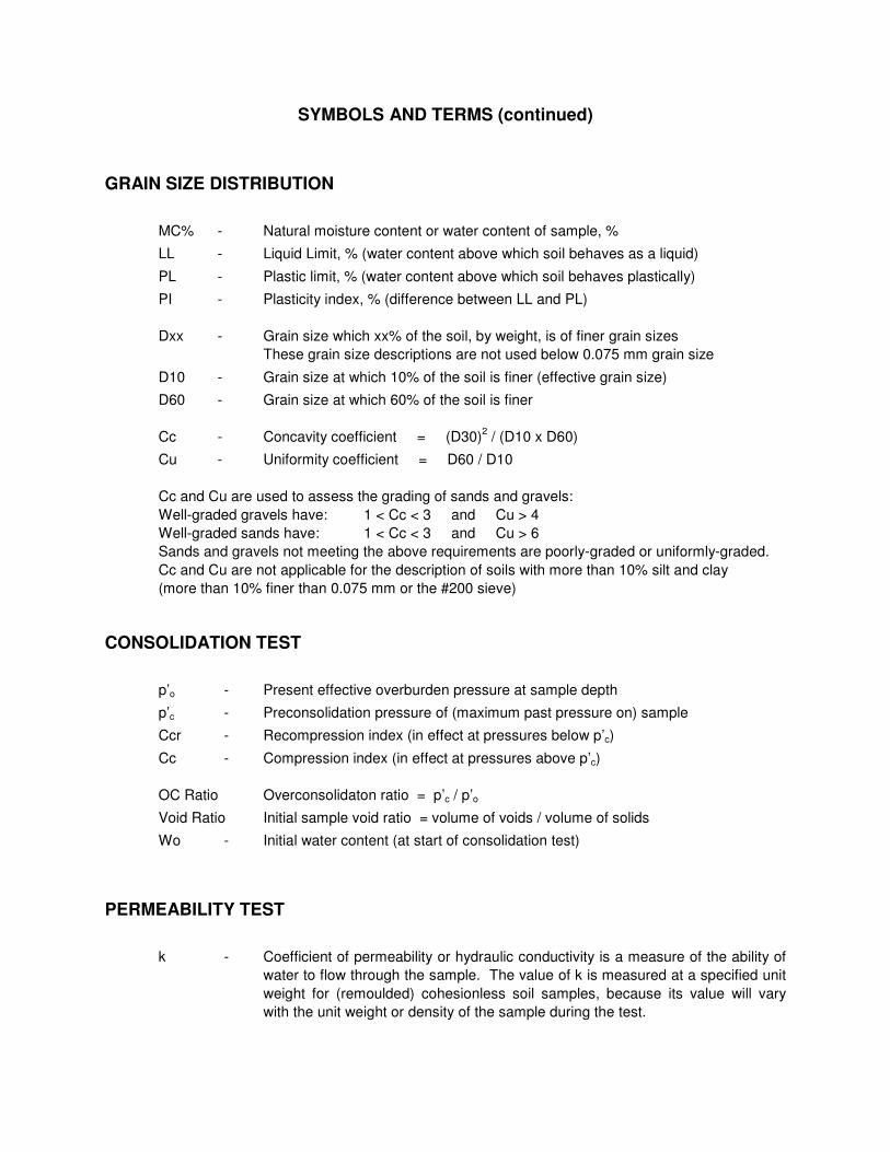
GRAIN SIZE DISTRIBUTION
MC% - Natural moisture content or water content of sample, %
LL - Liquid Limit, % (water content above which soil behaves as a liquid)
PL - Plastic limit, % (water content above which soil behaves plastically)
PI - Plasticity index, % (difference between LL and PL)
Dxx - Grain size which xx% of the soil, by weight, is of finer grain sizes
These grain size descriptions are not used below 0.075 mm grain size
D10 - Grain size at which 10% of the soil is finer (effective grain size)
D60 - Grain size at which 60% of the soil is finer
Cc - Concavity coefficient = (D30)2 / (D10 x D60)
Cu - Uniformity coefficient = D60 / D10
Cc and Cu are used to assess the grading of sands and gravels:
Well-graded gravels have: 1 < Cc < 3 and Cu > 4
Well-graded sands have: 1 < Cc < 3 and Cu > 6
Sands and gravels not meeting the above requirements are poorly-graded or uniformly-graded.
Cc and Cu are not applicable for the description of soils with more than 10% silt and clay
(more than 10% finer than 0.075 mm or the #200 sieve)
CONSOLIDATION TEST
p’o - Present effective overburden pressure at sample depth
p’c - Preconsolidation pressure of (maximum past pressure on) sample
Ccr - Recompression index (in effect at pressures below p’c)
Cc - Compression index (in effect at pressures above p’c)
OC Ratio Overconsolidaton ratio = p’c / p’o
Void Ratio Initial sample void ratio = volume of voids / volume of solids
Wo - Initial water content (at start of consolidation test)
PERMEABILITY TEST
k - Coefficient of permeability or hydraulic conductivity is a measure of the ability of
water to flow through the sample. The value of k is measured at a specified unit
weight for (remoulded) cohesionless soil samples, because its value will vary
with the unit weight or density of the sample during the test.

Order #: 1745368
Project Description: PG4315
Certificate of AnalysisClient:
Report Date: 10-Nov-2017
Order Date: 8-Nov-2017
Client PO: 23087
Paterson Group Consulting Engineers
Client ID: BH6-SS3 - - -
Sample Date: ---08-Nov-17
1745368-01 - - -Sample ID:
MDL/Units Soil - - -
Physical Characteristics
% Solids ---94.50.1 % by Wt.
General Inorganics
pH ---8.120.05 pH Units
Resistivity ---10.10.10 Ohm.m
Anions
Chloride ---2995 ug/g dry
Sulphate ---825 ug/g dry
Page 3 of 7
APPENDIX 2
FIGURE 1 - KEY PLAN
DRAWING PG4315-1 - TEST HOLE LOCATION PLAN
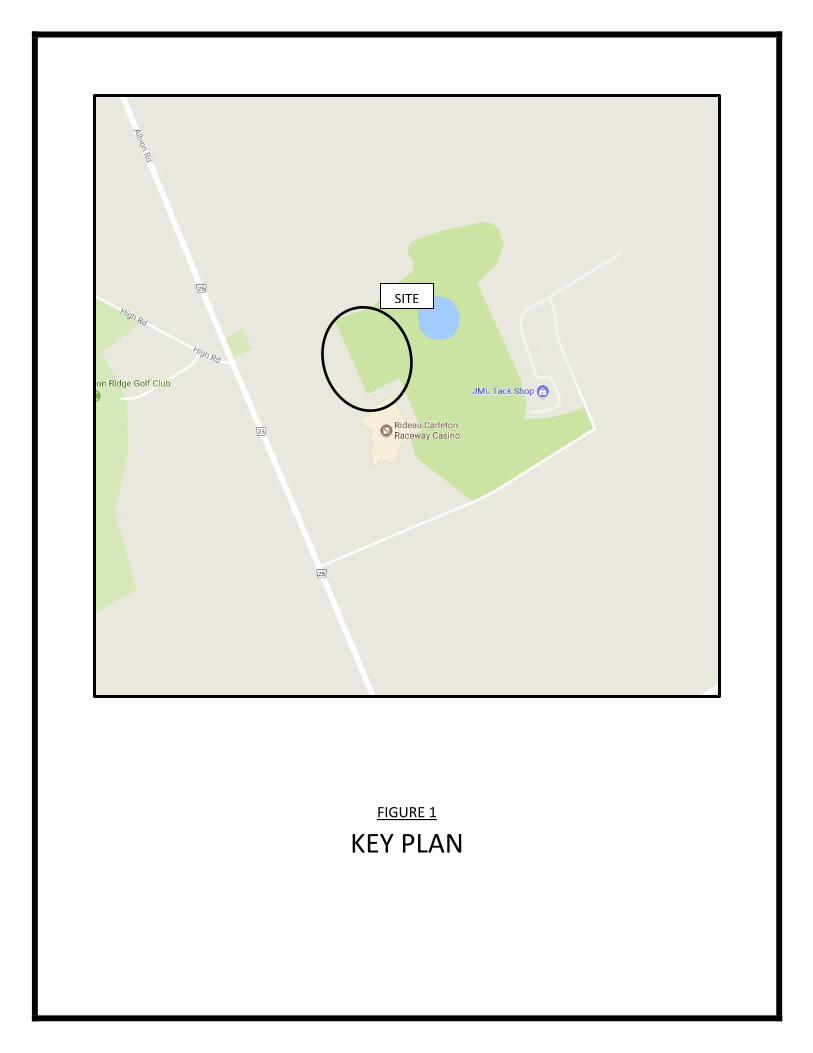
FIGURE 1
KEY PLAN
SITE

A
P
P
R
O
X
IM
A
T
E
LO
C
A
T
IO
N
O
F
F
IB
R
E
O
P
T
IC
S
C
A
B
LE
S
M
H
F
IB
E
R
O
P
T
IC
S
FIB
ER
OP
TIC
S C
AB
LE
JUP
EXISTING
ASPHALT
ENTRANCE
EXISTING GRAVEL
ENTRANCE
RIP-RAP
EX
ISTIN
G
DR
IVEW
AY
EX
ISTIN
G
DR
IVEW
AY
EXISTING
GRAVEL
ENTRANCE
EXISTING
GRAVEL
ENTRANCE
E
X
IS
T
IN
G
D
R
IV
E
W
A
Y
BP
EX GRAVEL
ENTRANCE
MA
SIGN
CFMAMAMA
JUP
SIGN
SIGN
MB
MB
MB
MB
EX RIP-RAP LINED DITCH
PO
ST
PO
ST
BP
THH
THH
THH
G
R
A
V
E
L
R
A
C
E
T
R
A
C
K
P
O
S
T
&
W
I
R
E
F
E
N
C
E
POST & WIRE FENCEPOST & WIRE FENCE
G
R
A
V
E
L
EX
IST
ING
SIG
N
WINNERS
CIRCLE
EX. BOTTOM OF SLOPE
EX
. B
O
TT
O
M
O
F S
LO
PE
EX. TOP O
F BANK
EX TOP OF BANK
EX
. TO
P O
F BA
NK
E
X
. T
O
P
O
F
B
A
N
K
E
X
.
T
O
P
O
F
B
A
N
K
EXISTING GRAVEL PARKING LOT
E
X
IS
T
IN
G
A
S
P
H
A
L
T
EX
IS
TIN
G C
EM
ET
AR
Y
EX
C
O
F R
OA
D
L
EXISTING ASPHALTEXISTING WOOD PICKET
FENCE C/W STONE PILLARS
EXISTING ASPHALT
EXISTING ASPHALT PARKING LOT
EXISTING BUS PAD
GRAVEL
GRASS
GRASS
GRASS
BP
BP
EXISTING GRANDSTAND
EX
IS
TIN
G
B
US
HLIN
E
DIRT TRACK
30.6m
E
X
IS
T
IN
G
150Ø
S
A
N
EX
D
IT
CH
CL/DITCH
CL/D
ITC
H
EX
. D
ITC
H
EX
. D
ITC
H
C
L/D
IT
C
H
EX
. D
ITC
H
EX
. D
ITC
H
EX
. D
IT
CH
EX
D
IT
CH
EX
D
IT
CH
EX
D
IT
CH
E
X
D
IT
C
H
EX
308.2m
- 150m
mØ
H
DP
E S
AN
F
OR
CE
MA
IN
EX 59.9m - 250mmØ SAN @
0.28%
EX
85m
- 250m
mØ
SA
N @
0.2
5%
E
X
7
5
m
-
2
5
0
m
m
Ø
S
A
N
@
0
.
3
3
%
EX
54.0
m -
250m
mØ
SA
N @
0.2
9%
EX SAN (ABANDONED)
EX SAN
OVERFLOW
EX 21.5m - 250mmØ SAN @
0.28%
EX 13.9m -
250mmØ SAN @
0.90%
PA
TH
WA
Y
EX SAN STUB
(ABANDONED)
SANITARY LIFT STATION
S INV = 105.16
N INV = 107.29
BASE ELEV = 103.44
EX SAN MH
T/G = 111.23
W INV = 107.06
E INV = 106.97
EX SAN MH
T/G = 109.81
W INV = 106.84
N INV = 106.62
E INV = 106.57
EX SAN MH
T/G = 108.50
W INV = 106.55
N INV = 106.48
S INV = 106.61
W INV = 106.51
S INV = 107.40
EX SAN STUB
(ABANDONED)
EX SAN MH
T/G = 108.50
S INV = 105.93
N INV = 105.87
ENINV = 105.83
EX SAN STUB
(ABANDONED)
EX SAN MH
T/G = 110.86
S INV = 105.34
N INV = 105.33
E
X
2
0
0
m
m
Ø
P
V
C
W
M
E
X
2
0
0
m
m
Ø
P
V
C
W
M
EX
200m
mØ
P
VC
W
M
EXISTING GENERATOR BUILDING
EX SAN (ABANDONED)
EXISTING ELECTRICAL PANEL
EXISTING
ELECTRICAL
PANEL
EX 450mmØ CSP
E INV = 112.55
W INV = 112.55
EXISTING
ELECTRICAL
PANEL
EX CSP
CULVERT
EX CSP
CULVERT
EX 600mmØ
CULVERT
EX 600mmØ
CULVERT
EX 600mmØ
CULVERT
EXISTING ASPHALT PARKING LOT
EXISTING ASPHALT PARKING LOT
EXISTING ASPHALT PARKING LOT
EXISTING ASPHALT PARKING LOT
EXISTING ASPHALT PARKING LOT
EXISTING ASPHALT PARKING LOT
EXISTING ASPHALT PARKING LOT
EXISTING 3m
HIGH FENCE
EX
IS
TIN
G W
AT
ER
S
ER
VIC
E
APPROX LOCATION OF
BURIED TRAFFIC DUCTS
A L B I O N R O A D
HIGH R
OAD
BH 1113.47
BH 2113.80
BH 3114.24
BH 5114.72(103.62)
BH 6114.20
BH 7
BH 8
BH 9110.61(101.11)
BH 10111.06
BH 11110.51(100.86)
BH 4114.17
110.72(103.10)
111.30
TBM-T/GMH
OTTAWA, ONTARIO
consulting engineerspaterson
NO. REVISIONS DATE INITIAL
HARD ROCK OTTAWA
GEOTECHNICAL INVESTIGATION
PROPOSED BUILDING EXPANSION - 4837 ALBION ROAD
TEST HOLE LOCATION PLAN
PG4315-1
1:2000
Title:
Scale:
Drawn by:
Checked by:
group
p:\au
tocad
draw
ings\g
eotec
hnica
l\pg4
3xx\p
g431
5\pg4
315-
1 thlp
[251]
revis
ion 1
4837
albio
n roa
d aer
ial -
final
2013
.dwg
154 Colonnade Road South
Ottawa, Ontario K2E 7J5
Tel: (613) 226-7381 Fax: (613) 226-6344
Approved by:
Revision No.:
MPG
NZ
DJG
11/2017
Date:
Report No.:
PG4315-1
Dwg. No.:
0
0
0 25 50 75 100 125 150m
LEGEND:
BOREHOLE LOCATION
114.72 GROUND SURFACE ELEVATION (m)
(103.62) PRACTICAL REFUSAL TO DCPT / AUGER
ELEVATION (m)
TBM - TOP OF GRATE OF MANHOLE. GEODETIC
ELEVATION = 112.16m.PROVIDED BY NOVATECH
ENGINEERING LTD.