pgr-6300 manual motor protection system -...
TRANSCRIPT
POWR-GARD® Motor Protection PGR-6300 SERIES
Motor Protection System
PGR-6300 MANUAL
MOTOR PROTECTION SYSTEM
JULY 16, 2009
Revision 4
Copyright © 2009 by Littelfuse, Inc.
All rights reserved. Publication: PGR-6300-M Document: P95-M320-00000 Printed in Canada.
Factory default password is 1111 New Password See Section 4.3.6.
Motor Identification
Page i PGR-6300 Motor Protection System Rev. 4
Pub. PGR-6300-M. July 16, 2009 www.littelfuse.com/protectionrelays © 2009 Littelfuse • POWR-GARD®
TABLE OF CONTENTS Page Table of Contents............................................................i List of Figures................................................................. ii List of Tables.................................................................. ii Disclaimer...................................................................... iii 1. INTRODUCTION ............................................ 1-1 1.1 General ............................................................ 1-1 1.2 PGR-6300 Features ........................................ 1-1 1.2.1 Protection ............................................ 1-1 1.2.2 Control—Starting Methods................. 1-1 1.2.3 Metering............................................... 1-1 1.2.4 Data Logging....................................... 1-1 1.2.5 Inputs and Outputs.............................. 1-1 1.2.6 OPI Operator Interface ....................... 1-2 1.2.7 PGA-0120 Temperature Input Module............................................. 1-2 1.2.8 PGA-0140 Differential Current Module............................................. 1-2 1.2.9 Communications Interface.................. 1-2 1.3 Ordering Information ....................................... 1-2 2. INSTALLATION .............................................. 2-1 2.1 General ............................................................ 2-1 2.2 CTU Control Unit ............................................. 2-1 2.3 OPI Operator Interface.................................... 2-1 2.4 PGA-0120 Temperature Input Module........... 2-1 2.5 PGA-0140 Differential Current Module .......... 2-1 2.6 Sensitive Earth-Fault CT’s .............................. 2-1 3. SYSTEM WIRING ........................................... 3-1 3.1 General ............................................................ 3-1 3.2 Wiring Connections ......................................... 3-1 3.2.1 CTU Connections................................ 3-1 3.2.1.1 Supply Voltage ........................ 3-1 3.2.1.2 Current Inputs.......................... 3-1 3.2.1.3 Voltage Inputs.......................... 3-1 3.2.1.3.1 Direct Connection .... 3-3 3.2.1.3.2 1-PT Connection...... 3-3 3.2.1.3.3 2-PT Connection...... 3-3 3.2.1.3.4 3-PT Connection...... 3-3 3.2.1.4 Digital Inputs ............................ 3-3 3.2.1.4.1 DC Operation ........... 3-3 3.2.1.4.2 AC Operation ........... 3-4 3.2.1.4.3 Combined AC and DC Operation ......... 3-4 3.2.1.4.4 Tachometer Input (HSI) .............. 3-4 3.2.1.5 Analog Input (AN IN) ............... 3-4 3.2.1.6 Analog Output (AN OUT)........ 3-4 3.2.1.7 PTC Input................................. 3-4 3.2.1.8 IRIG-B Input............................. 3-4 3.2.1.9 I/O Module Communication .... 3-4 3.2.1.10 RS-485 Network Communications................... 3-4 3.2.2 OPI Connections and Address Selection............................ 3-4
Page 3.2.3 PGA-0120 Connections and Address Selection ............................3-5 3.2.4 PGA-0140 Connections......................3-5 3.2.4.1 Core Balance...........................3-5 3.2.4.2 PGR-6300 Summation............3-5 3.2.4.3 DIF Summation........................3-5 3.2.5 Dielectric-Strength Testing .................3-5 4. OPERATION AND SETUP ............................4-1 4.1 General ............................................................4-1 4.2 CTU .............................................................4-1 4.2.1 LED Indication.....................................4-1 4.2.2 Reset Switch .......................................4-1 4.2.3 Phase-CT Inputs .................................4-1 4.2.4 Earth-Fault-CT Input ...........................4-2 4.2.5 Voltage Inputs .....................................4-2 4.2.6 Motor Data...........................................4-2 4.2.7 Output Relay Assignment...................4-2 4.2.8 Digital Inputs 1 to 7 .............................4-3 4.2.9 Tachometer Input (HSI) ......................4-4 4.2.10 Analog Output .....................................4-4 4.2.11 Analog Input ........................................4-5 4.2.11.1 Metering only.........................4-5 4.2.11.2 Protection...............................4-5 4.2.11.3 Synchronize to ASD..............4-5 4.2.11.4 Motor Speed..........................4-5 4.2.12 Starter ..................................................4-5 4.2.13 Protection ............................................4-5 4.2.14 Miscellaneous Configuration ..............4-5 4.2.15 Network Communications ..................4-5 4.3 OPI ...............................................................4-5 4.3.1 General ................................................4-5 4.3.2 Configuring the CTU for OPI Operation ..................................4-5 4.3.3 Starter Control .....................................4-6 4.3.3.1 OPI Control..............................4-6 4.3.3.2 Local Control ...........................4-6 4.3.3.3 Remote Control .......................4-6 4.3.4 Metering...............................................4-7 4.3.5 Messages ............................................4-7 4.3.5.1 Trip Reset ................................4-7 4.3.5.2 Status.......................................4-7 4.3.5.3 Data Logging ...........................4-9 4.3.5.4 Statistical Data.........................4-9 4.3.5.5 Emergency Thermal Reset.....4-9 4.3.6 Password Entry and Programming ....4-9 4.4 PGA-0120 ......................................................4-10 4.5 PGA-0140 ......................................................4-10 5. PROTECTIVE FUNCTIONS ....................... 5-1 5.1 General........................................................ 5-1 5.2 Overload...................................................... 5-1 5.2.1 Thermal Model................................. 5-1 5.2.2 Locked-Rotor Times ........................ 5-4 5.2.3 Emergency Thermal Reset.............. 5-4 5.3 Overcurrent.................................................. 5-4 5.4 Auxiliary Overcurrent................................... 5-5
Page ii PGR-6300 Motor Protection System Rev. 4
Pub. PGR-6300-M. July 16, 2009 www.littelfuse.com/protectionrelays © 2009 Littelfuse • POWR-GARD®
Page 5.5 Reduced Overcurrent ..................................5-5 5.6 Jam..............................................................5-5 5.7 Earth Fault ...................................................5-5 5.8 Current Unbalance ......................................5-5 5.9 Phase Loss—Current ..................................5-6 5.10 Phase Reverse—Current ............................5-6 5.11 Undercurrent................................................5-6 5.12 Overvoltage .................................................5-6 5.13 Voltage Unbalance ......................................5-6 5.14 Phase Loss—Voltage ..................................5-6 5.15 Phase Reverse—Voltage ............................5-6 5.16 Undervoltage ...............................................5-6 5.17 Power Factor—Quadrant 4..........................5-7 5.18 Power Factor—Quadrant 3..........................5-7 5.19 Underfrequency ...........................................5-7 5.20 Overfrequency .............................................5-7 5.21 Starts per Hour/Time Between Starts..........5-7 5.22 Failure to Accelerate and Underspeed........5-8 5.23 Differential Current Protection .....................5-8 5.24 PTC Temperature........................................5-8 5.25 RTD Temperature........................................5-8 5.26 Hot-Motor Compensation ............................5-9 5.27 Analog Input.................................................5-9 5.27.1 Protection ........................................5-9 5.27.2 Synchronize to ASD ........................5-9 5.27.3 Motor Speed....................................5-9 6. STARTER FUNCTIONS..............................6-1 6.1 General ........................................................6-1 6.2 Starter Timing Sequences ...........................6-3 6.3 Full-Voltage Non-Reversing Starter ............6-6 6.4 Adjustable-Speed Drive...............................6-6 6.5 Soft-Start Starter..........................................6-6 6.6 Full-Voltage Reversing Starter ....................6-7 6.7 Two-Speed Starter ......................................6-7 6.8 Reactor or Resistor Closed-Transition Starter .......................................................6-9 6.9 Slip-Ring Starter ..........................................6-9 6.10 Part-Winding and Double-Delta Starters ...6-10 6.11 Soft-Start-With-Bypass Starter ..................6-11 6.12 Reactor or Resistor Open-Transition Starter .....................................................6-11 6.13 Two-Winding Starter..................................6-11 6.14 Wye-Delta Open-Transition Starter ...........6-11 6.15 Autotransformer Closed-Transition Starter .....................................................6-12 6.16 Wye-Delta Closed-Transition Starter.........6-12 7. THEORY OF OPERATIONS.......................7-1 7.1 Signal-Processing Algorithms......................7-1 7.2 Power Algorithm ..........................................7-1 7.3 Operator Interface (OPI)..............................7-1 7.4 PGA-0120 Temperature Input Module ........7-1 7.5 PGA-0140 Differential Current Module........7-1 7.6 Firmware Diagnostics ..................................7-1
Page 8. COMMUNICATIONS................................... 8-1 8.1 Personal Computer Interface ...................... 8-1 8.1.1 Firmware Upgrade........................... 8-1 8.1.2 PGW-COMM.................................... 8-1 8.2 Network Interface ........................................ 8-1 8.2.1 RS-485 Communications................. 8-1 8.2.2 DeviceNet Communications ............ 8-1 8.2.3 Ethernet Communications ............... 8-1 8.2.4 Profibus DP Communications.......... 8-1 9. TECHNICAL SPECIFICATIONS ................ 9-1 9.1 Control Unit (CTU)....................................... 9-1 9.2 Operator Interface (OPI).............................. 9-2 9.3 Temperature Input Module (PGA-0120)...... 9-3 9.4 Differential Current Module (PGA-0140) ..... 9-3 Appendix A PGR-6300 Menu Map.......................A-1 Appendix B PGR-6300 Set-Up Record................B-1 Appendix C PGR-6300 Modbus Protocol ............C-1 Appendix D PGR-6300 A-B DF1 Protocol ...........D-1 Appendix E Communications Database Table ....E-1 Appendix F Register Formats ..............................F-1

Page iii PGR-6300 Motor Protection System Rev. 4
Pub. PGR-6300-M. July 16, 2009 www.littelfuse.com/protectionrelays © 2009 Littelfuse • POWR-GARD®
LIST OF FIGURES Page 1.1 Motor Protection System Block Diagram ....... 1-3 1.2 PGR-6300 Ordering Information .................... 1-4 2.1 CTU Outline and Mounting Details................. 2-2 2.2 OPI Outline and Mounting Details .................. 2-3 2.3 CTU with OPI Outline and Mounting Details........................................... 2-4 2.4 PGA-0120 Outline and Mounting Details....... 2-5 2.5 PGA-0140 Outline and Mounting Details....... 2-6 2.6 PGC-3026 Outline and Mounting Details....... 2-7 2.7 PGC-3082 Outline and Mounting Details....... 2-8 2.8 PGC-3140 Outline and Mounting Details....... 2-9 3.1 Residual Phase-CT Connection ..................... 3-1 3.2 Typical PGR-6300 Connection Diagram........ 3-2 3.3 Direct Connection............................................ 3-3 3.4 1-PT Connection.............................................. 3-3 3.5 2-PT Connection.............................................. 3-3 3.6 3-PT Connection.............................................. 3-3 3.7 Digital Tachometer Input (HSI) ....................... 3-4 3.8 Address Selection Switch Detail..................... 3-5 3.9 Two Examples of I/O Module Connections.... 3-6 3.10 PGA-0120 Connection Diagram..................... 3-7 3.11 Core Balance Connection............................... 3-8 3.12 PGR-6300 Summation Connection................ 3-8 3.13 DIF Summation Connection............................ 3-9 4.1 Menu Example................................................. 4-1 4.2 Menu Symbols................................................. 4-1 4.3 OPI Interface.................................................... 4-6 5.1 Class-20 Overload Curve................................ 5-3 5.2 Asymmetrical-Current Multipliers.................... 5-5 5.3 Used I2t Bias Curve ......................................... 5-9 6.1 Typical 3-Wire Control..................................... 6-3 6.2 Typical 2-Wire Control..................................... 6-3 6.3 Starter Sequence 1 ......................................... 6-3 6.4 Starter Sequence 2 ......................................... 6-4 6.5 Starter Sequence 3 ......................................... 6-4 6.6 Starter Sequence 4 ......................................... 6-4 6.7 Starter Sequence 5 ......................................... 6-5 6.8 Starter Sequence 6 ......................................... 6-5 6.9 Full-Voltage Non-Reversing-Starter Connection.................................................... 6-6 6.10 Adjustable-Speed-Drive Connection .............. 6-6 6.11 Soft-Start-Starter Connection ......................... 6-6 6.12 Full-Voltage-Reversing-Starter Connection ... 6-7 6.13 Two-Speed Two-Winding-Starter Connection.................................................... 6-7 6.14 Two-Speed Constant- and Variable-Torque- Starter Connections...................................... 6-8 6.15 Two-Speed Constant-Horsepower-Starter Connection................................................... 6-8 6.16 Reactor or Resistor-Starter Connection......... 6-9 6.17 Slip-Ring-Starter Connection.......................... 6-9 6.18 Part-Winding and Double-Delta-Starter Connections................................................6-10 6.19 Soft-Start-With-Bypass-Starter Connection .6-11
Page
6.20 Two-Winding-Starter Connection .................6-11 6.21 Wye-Delta Open-Transition-Starter Connection..................................................6-12 6.22 Autotransformer Closed-Transition-Starter Connection..................................................6-13 6.23 Wye-Delta Closed-Transition-Starter Connection..................................................6-13 LIST OF TABLES Page 3.1 OPI Address Selection ....................................3-4 3.2 PGA-0120 Address Selection.........................3-5 4.1 Output-Relay Functions ..................................4-2 4.2 Digital-Input Functions.....................................4-3 4.3 Analog-Output Parameters .............................4-4 4.4 Metering Display..............................................4-8 4.5 Status Messages.............................................4-8 5.1 Trip Time..........................................................5-4 5.2 Fault Duration Required for Trip .....................5-4 6.1 Start-Source Summary....................................6-1 6.2 Starter Summary .............................................6-2
DISCLAIMER Specifications are subject to change without notice. Littelfuse, Inc. is not liable for contingent or consequential damages, or for expenses sustained as a result of incorrect application, incorrect adjustment, or a malfunction. This product has a variety of applications. Those responsible for its application must take the necessary steps to assure that each installation meets all performance and safety requirements including any applicable laws, regulations, codes, and standards. Information provided by Littelfuse is for purposes of example only. Littelfuse does not assume responsibility for liability for use based upon the examples shown.

Page iv PGR-6300 Motor Protection System Rev. 4
Pub. PGR-6300-M. July 16, 2009 www.littelfuse.com/protectionrelays © 2009 Littelfuse • POWR-GARD®
This page intentionally left blank.
Page 1-1 PGR-6300 Motor Protection System Rev. 4
Pub. PGR-6300-M. July 16, 2009 www.littelfuse.com/protectionrelays © 2009 Littelfuse • POWR-GARD®
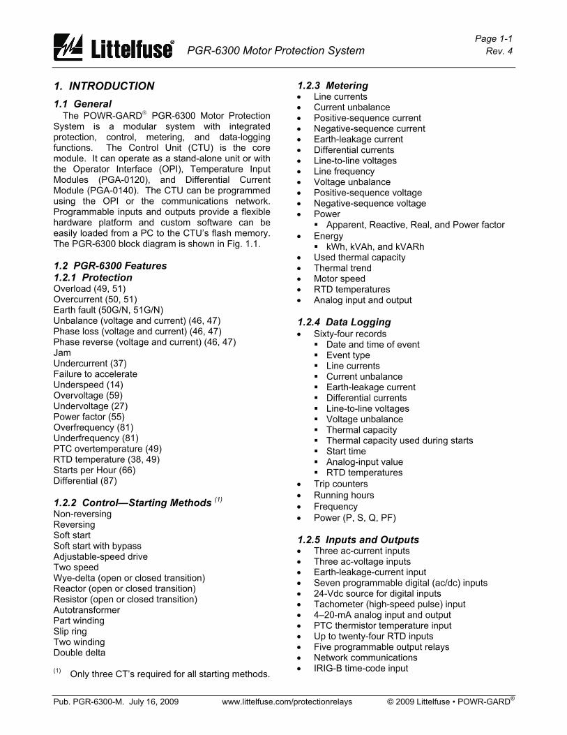
1. INTRODUCTION 1.1 General The POWR-GARD® PGR-6300 Motor Protection System is a modular system with integrated protection, control, metering, and data-logging functions. The Control Unit (CTU) is the core module. It can operate as a stand-alone unit or with the Operator Interface (OPI), Temperature Input Modules (PGA-0120), and Differential Current Module (PGA-0140). The CTU can be programmed using the OPI or the communications network. Programmable inputs and outputs provide a flexible hardware platform and custom software can be easily loaded from a PC to the CTU’s flash memory. The PGR-6300 block diagram is shown in Fig. 1.1. 1.2 PGR-6300 Features 1.2.1 Protection Overload (49, 51) Overcurrent (50, 51) Earth fault (50G/N, 51G/N) Unbalance (voltage and current) (46, 47) Phase loss (voltage and current) (46, 47) Phase reverse (voltage and current) (46, 47) Jam Undercurrent (37) Failure to accelerate Underspeed (14) Overvoltage (59) Undervoltage (27) Power factor (55) Overfrequency (81) Underfrequency (81) PTC overtemperature (49) RTD temperature (38, 49) Starts per Hour (66) Differential (87) 1.2.2 Control—Starting Methods (1) Non-reversing Reversing Soft start Soft start with bypass Adjustable-speed drive Two speed Wye-delta (open or closed transition) Reactor (open or closed transition) Resistor (open or closed transition) Autotransformer Part winding Slip ring Two winding Double delta (1) Only three CT’s required for all starting methods.
1.2.3 Metering • Line currents • Current unbalance • Positive-sequence current • Negative-sequence current • Earth-leakage current • Differential currents • Line-to-line voltages • Line frequency • Voltage unbalance • Positive-sequence voltage • Negative-sequence voltage • Power
Apparent, Reactive, Real, and Power factor • Energy
kWh, kVAh, and kVARh • Used thermal capacity • Thermal trend • Motor speed • RTD temperatures • Analog input and output 1.2.4 Data Logging • Sixty-four records
Date and time of event Event type Line currents Current unbalance Earth-leakage current Differential currents Line-to-line voltages Voltage unbalance Thermal capacity Thermal capacity used during starts Start time Analog-input value RTD temperatures
• Trip counters • Running hours • Frequency • Power (P, S, Q, PF) 1.2.5 Inputs and Outputs • Three ac-current inputs • Three ac-voltage inputs • Earth-leakage-current input • Seven programmable digital (ac/dc) inputs • 24-Vdc source for digital inputs • Tachometer (high-speed pulse) input • 4–20-mA analog input and output • PTC thermistor temperature input • Up to twenty-four RTD inputs • Five programmable output relays • Network communications • IRIG-B time-code input
Page 1-2 PGR-6300 Motor Protection System Rev. 4
Pub. PGR-6300-M. July 16, 2009 www.littelfuse.com/protectionrelays © 2009 Littelfuse • POWR-GARD®
1.2.6 OPI Operator Interface • 4 x 20 vacuum-fluorescent display • Starter control keys • Display-control and programming keys • LED status indication • Remote operation up to 1.2 km (4,000’) • Powered by PGR-6300 Control Unit 1.2.7 PGA-0120 Temperature Input Module • Eight inputs per module • Individually selectable RTD types • Solid-state multiplexing • Up to three modules per system • Remote operation up to 1.2 km (4,000’) • Powered by PGR-6300 Control Unit 1.2.8 PGA-0140 Differential Current Module • 3-CT core balance connection • 6-CT summation connection • Remote operation up to 1.2 km (4,000’) • Powered by PGR-6300 Control Unit 1.2.9 Communications Interface The standard network communication interface is an RS-485 port with Modbus® RTU and A-B® DF1 protocol support. In addition to the standard interface, network communication options include DeviceNet™, Profibus®, Modbus® TCP, and Ethernet/IP.
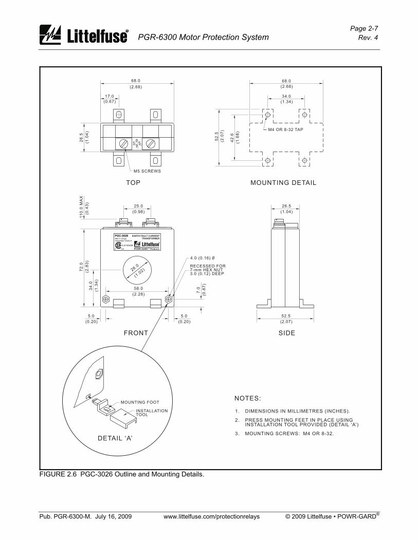
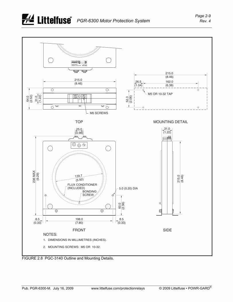
1.3 Ordering Information See Fig. 1.2 for CTU, OPI, PGA-0120, and PGA-0140 model numbers. Current Transformers: PGC-3026..................Sensitive Earth-Fault CT, 5-A-primary rating, 26-mm (1”) window PGC-3082..................Sensitive Earth-Fault CT, 5-A-primary rating, 82-mm (3.2”) window PGC-31FC .................Flux Conditioner for PGC-3082, 70-mm (2.7”) window PGC-3140..................Sensitive Earth-Fault CT With Flux Conditioner, 5-A-primary rating, 139-mm (5.5”) window Other Earth-Fault CT’s .Contact factory Phase CT’s ................Contact factory Accessories: PGA-0400 ..................Port-Powered Serial Converter PGA-0440 ..................USB to TIA-232 Serial Converter Software: PGW-COMM..............PC Interface(1)
PGW-FLSH................Firmware Upgrade(1)
(1) Available at www.littelfuse.com/protectionrelays

Page 1-3 PGR-6300 Motor Protection System Rev. 4
Pub. PGR-6300-M. July 16, 2009 www.littelfuse.com/protectionrelays © 2009 Littelfuse • POWR-GARD®
OUTPUT
RELAY 1
OUTPUT RELAY
CONTACTS SHOWN
CTU
DE-ENERGIZED.
WITH
OUTPUT
RELAY 5
OUTPUT
RELAY 2
OUTPUT
RELAY 3
OUTPUT
RELAY 4
24 V DC
OUTPUT
L1
L2
VA
VB
VC
1A
5A
C
1A
5A
C
C
5A
1A
C
5A
1A
COM
IN1
IN2
IN3
IN4
IN5
IN6
IN7
-
-
+
+
HSI
ANALOG INPUT
24-120 Vac/Vdc
DIGITAL INPUTS
PTC INPUT
PHASE
SUPPLY
VOLTAGE
INPUT
PHASE A
CURRENT
PHASE B
CURRENT
PHASE C
CURRENT
EARTH LEAKAGE
CURRENT
LED INDICATORS:
POWER
TRIP
ALARM
ERROR
RESET PUSHBUTTON
2
3
4
1
5
I/O COMMUNICATIONS
0V
+24V
++
+
--
-
PGR-6300OPERATORINTERFACE
(OPI)
4 x 20 ALPHANUMERICDISPLAY
CONTROL SELECT
START 1
START 2
STOP
RESET
ESC
ENTER
KEYPAD:
ADDRESS SWITCHES
REMOTE
OPI
LOCAL
RUN
STOP
START 1
START 2
TRIP
ALARM
LED INDICATORS:
PGR-6300CONTROL
UNIT(CTU)
S
VN
4-20 mA
4-20 mA
IRIG
ANALOG OUTPUT
RS-485 NETWORK
COMMUNICATIONS
1
2 8
9
10
11
12
13
14
15
16
60
56
59
57
58
39
62
36
37
35
40
61
7
6
5
SPG
SPGA
3
19
18
17
20
33
32
31
30
29
28
27
26
25
24
23
22
21
55
54
53
41
42
43
44
45
46
47
48
49
50
51
52
I/O COMMUNICATIONS
4
4A
OPTIONAL NETWORK
COMMUNICATIONS
TEMPERATUREINPUT
MODULE
SHIELD
SHIELD
SHIELD
SHIELD
R
R
C
C
D
D
D
D
C
C
R
R
14
16
17
15
18
7
21
2813
6
22
2912
5
23
3011
4
24
3110
3
25
329
2
26
338
1
27
34
20
19
RTD 4
RTD 2
RTD 5
RTD 7
R
R
C
C
SPG
D
D
D
D
C
C
R
R
RTD 3
RTD 1
RTD 6
RTD 8
+24V
+
-
PGA-0120
ADDRESS SWITCHES
PWR
COMM
LED INDICATORS:
CURRENT
1
4
7
C
C
C
2
5
8
5
5
5
3
6
9
1
1
1
13
11
12
10
+24V
-
+
0V
DIFFERENTIALCURRENTMODULE
PGA-0140
PWR
COMM
LED INDICATORS:
DIFFERENTIAL
0V
INPUT
INPUT
INPUT
INPUT
SPG 14
15
INPUT
PHASE C
CURRENTDIFFERENTIAL
INPUT
PHASE B
CURRENTDIFFERENTIAL
INPUT
PHASE A
FIGURE 1.1 Motor Protection System Block Diagram.

Page 1-4 PGR-6300 Motor Protection System Rev. 4
Pub. PGR-6300-M. July 16, 2009 www.littelfuse.com/protectionrelays © 2009 Littelfuse • POWR-GARD®
MAIN MENUMetering Ñ
²Messages ÑSetup Ñ
PHASE CURRENTEARTH
LEAKAGE
VOLTAGE
VN
VA
VB
VC
5 A5 A5 A5 A
1 A1 A1 A1 A
EFCTCBA
--- +++ +0V
SH
COMM24V
IR IGANIN
PTC
I/O MODULE
62 6061 59 57 5558 56 54 5253
33 32 31 30 29 28 27 26 25 24 23 22 21
20 19 18 17
PGR-6300-
Communications:01 Standard RS-485
(Includes A-B &Modbus Protocols)
02 DeviceNet andstandard RS-485
03 Profibus andstandard RS-485
04 Ethernet andstandard RS-485
®
®
®
Supplied Interconnect Cable:
3124A . . . . . . I/O Module to PGR-6300 Interconnect Cable,4 m (13’) included with PGA-0120 and PGA-0140
TM
PWR COMM
PGA-0120
PGA-0140
PGR-6200
PGR-6300
POWR-GARD
TEMPERATURE INPUT MODULE PGA-0120PGA-0120
PWR
COMM
31
SH
24V
COMM
0V
INP 8 INP 7 INP 6 INP 5
INP 1 INP 2 INP 3 INP 4
34 33 32 30 29 28 27 26 25 24 23 22 21 20 19
SPG
C D R C D R C D R C D RSH
1 2 3 4 5 6 7 8 9 10 11 12 13 14
R D C R D C R D C R D CSH
SH
15 16 17 18
INTERFACE
MOTOR PROTECTION SYSTEM
CONTROL UNIT
PGR-6300 SERIESPGR-6300 SERIES
POWR-GARD
++
62 61 60 59 58 57 56 55 54 53 52
IRIG
2
4
V
S
H
0
V
COMM
I/O MODULE
PTC
AN IN
35 36 37 39 40
S
H
COMM
AN
OUT
POWER
TRIP
ALARM
ERROR
RESET
41 42 43 44 45 46 47 48 49 50 51
24 VDC
SOURCE
DIGITAL INPUTS
C
O
M
I
N
1
I
N
2
I
N
3
I
N
4
I
N
5
I
N
6
I
N
7
H
S
I
- +
+
PGR-6200
PGR-6300
POWR-GARD
DIFFERENTIAL CURRENT MODULE PGA-0140PGA-0140
24V
COMM
0V
PHASE A PHASE B PHASE C
15 14
SPG
1 2 3 4 5 6 7 8 9
C 5 1 C 5 1 C 5 1
10 11 12 13
PGR-6300 SERIESPGR-6300 SERIESMOTOR PROTECTION SYSTEM
POWR-GARD
RESET
ESC
ENTERSTOP
START
1
START
2
CONTROL
SELECTTRIP
ALARM
REMOTE
OPI
LOCAL
RUN
STOP
-00
NOTE:
The PGR-6300 consists of the ControlUnit (CTU) and the Operator Interface (OPI).To order the Control Unit only, add (-CTU)to the part number above.To order the Operator Interface only,use PGR-6300-OPI-01-00.
CTU
OPI
FIGURE 1.2 PGR-6300 Ordering Information.
Page 2-1 PGR-6300 Motor Protection System Rev. 4
Pub. PGR-6300-M. July 16, 2009 www.littelfuse.com/protectionrelays © 2009 Littelfuse • POWR-GARD®
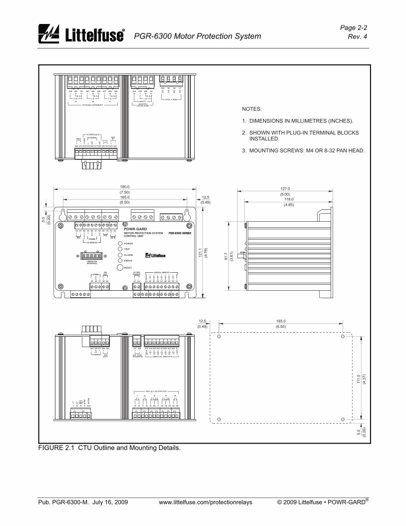
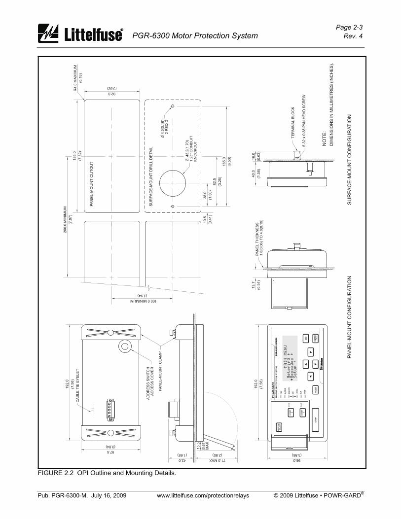
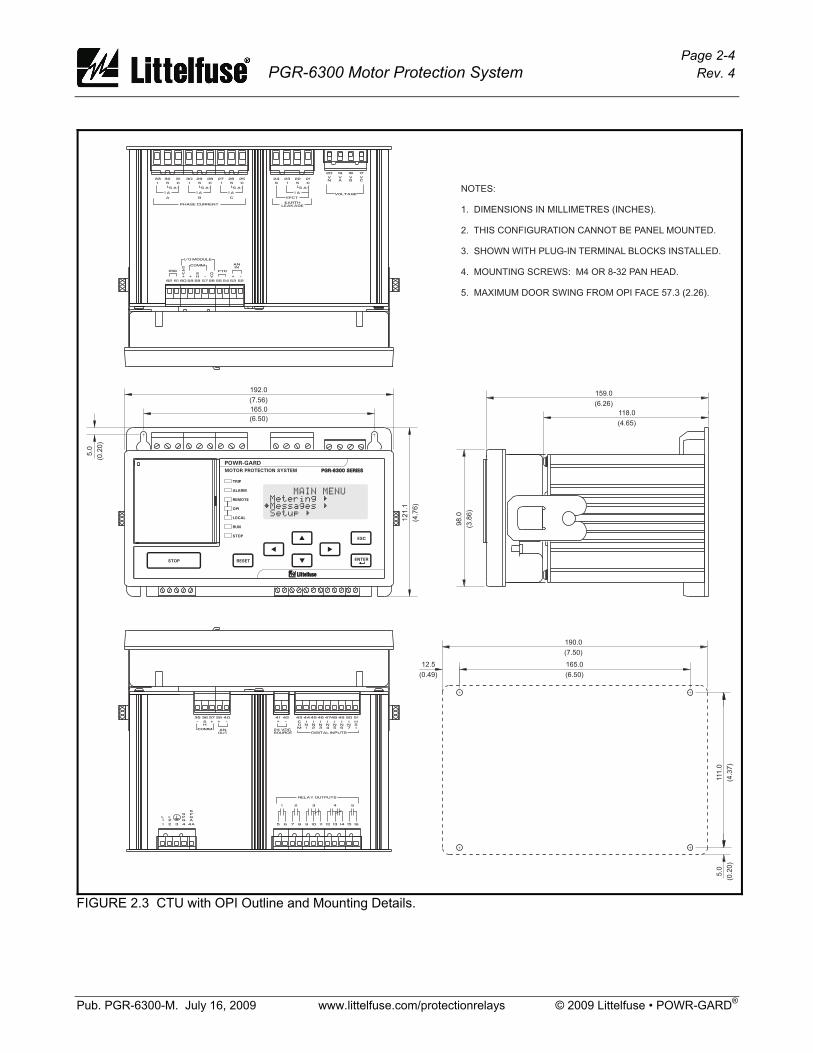
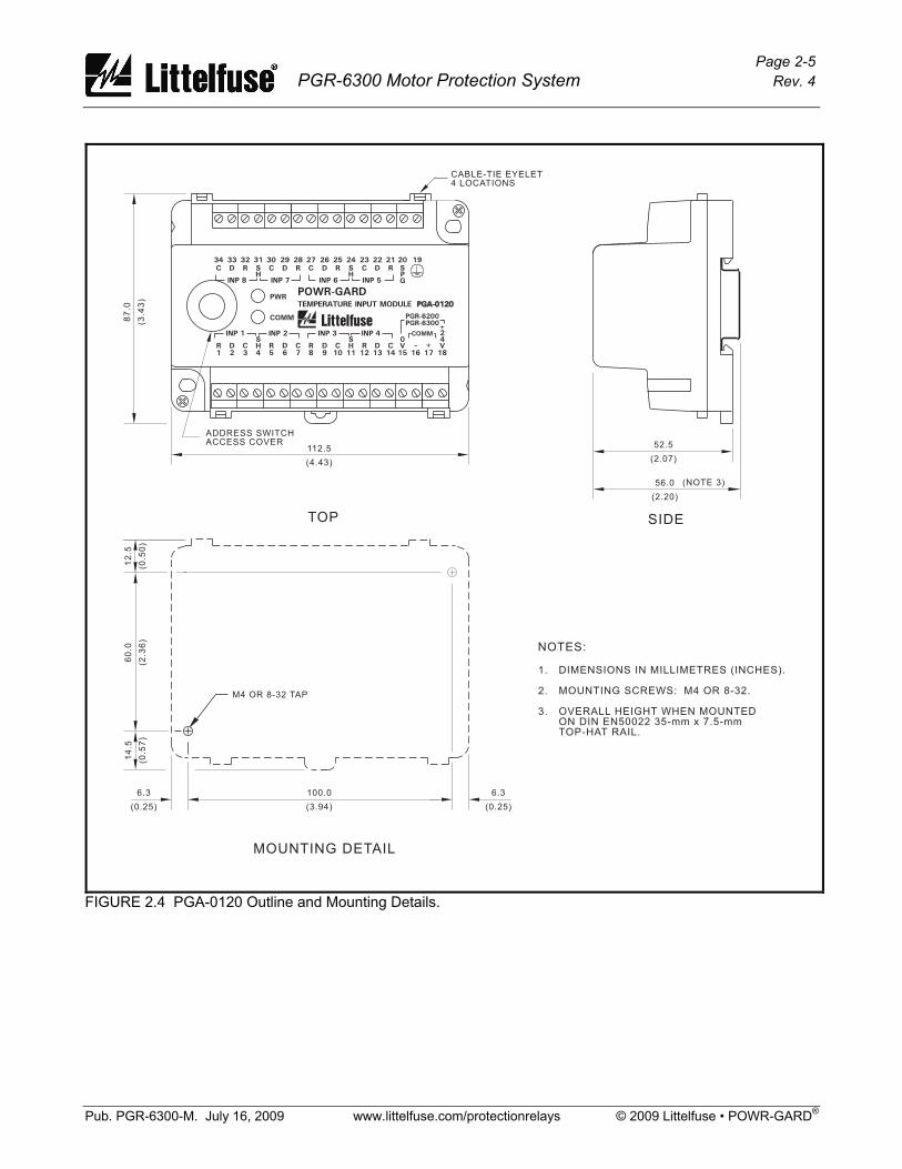
2. INSTALLATION 2.1 General A basic PGR-6300 Motor Protection System consists of a Control Unit (CTU) and three customer-supplied current transformers (CT's) for measuring phase current. For core-balance earth-fault detection, a 1-A, 5-A, PGC-3026, PGC-3082, or PGC-3140 CT is required. The residual phase-CT connection can also be used for earth-fault detection. Voltage inputs do not require potential transformers (PT’s) for system voltages up to 600 Vac. For RTD-temperature measurement, up to three PGA-120 RTD modules can be connected to the CTU. For differential protection a PGA-0140 module can be connected to the CTU. The OPI provides an operator interface for the PGR-6300. The PGR-6300 power-factor corrected switch-mode power supply is rated 65 to 265 Vac and 80 to 275 Vdc. All modules can be mounted in any orientation. 2.2 CTU Control Unit The Control Unit is configured for surface mounting. Outline and mounting details for the CTU are shown in Fig. 2.1. 2.3 OPI Operator Interface Outline and mounting details for the OPI are shown in Fig. 2.2. It is certified for use in Class I, Zone 2 hazardous locations. The Operator Interface is configured for panel mounting or it can be mounted on the CTU as shown in Fig. 2.3. 2.4 PGA-0120 Temperature Input Module Outline and mounting details for the PGA-0120 are shown in Fig. 2.4. The PGA-0120 will fit inside most motor RTD-termination junction boxes and it is certified for use in Class I, Zone 2 hazardous locations. The PGA-0120 can be surface or DIN-rail mounted. 2.5 PGA-0140 Differential Current Module Outline and mounting details for the PGA-0140 are shown in Fig 2.5. The PGA-0140 can be surface or DIN-rail mounted. 2.6 Sensitive Earth-Fault CT’S Outline and mounting details for the PGC-3026, PGC-3082, and PGC-3140 are shown in Fig. 2.6, 2.7, and 2.8.
Page 2-2 PGR-6300 Motor Protection System Rev. 4
Pub. PGR-6300-M. July 16, 2009 www.littelfuse.com/protectionrelays © 2009 Littelfuse • POWR-GARD®
NOTES:
1. DIMENSIONS IN MILLIMETRES (INCHES).
2. SHOWN WITH PLUG-IN TERMINAL BLOCKSINSTALLED.
3. MOUNTING SCREWS: M4 OR 8-32 PAN HEAD.
118.0
91.7
127.0
(4.65)
(3.6
1)
(5.00)165.0 12.5
121.1
5.0
190.0
(6.50) (0.49)(4
.76)
(0.2
0)
(7.50)
165.0
111.0
5.0
12.5
(6.50)
(4.3
7)
(0.2
0)
(0.49)
RELAY OUTPUTS
1 2 3 4 5
IN1
IN2
COM
IN3
-+ IN4
IN5
IN6
IN7
HSI
D IG ITAL INPUTS24 VDCSOURCE
5 6 87 9 1110 12 1413 15 16
5150494847464544434241
L1
L2
SPG
SPGA
-- ++
ANOUT
SH
COMM
1 2 4 4A3
4039373635
33
PHASE CURRENT
5 A5 A5 A
1 A1 A1 A
CBA
--- +++ +0V
SH
COMM24V
IR IGANIN
PTC
I/O MODULE
62 6061 59 57 5558 56 54 5253
32 31 30 29 28 27 26 25
EARTHLEAKAGE
VOLTAGE
VN
VA
VB
VC
5 A
1 A
EFCT
24 23 22 21
20 19 18 17
++
POWER
TRIP
ALARM
ERROR
RESET
MOTOR PROTECTION SYSTEM
CONTROL UNIT
PGR-6300 SERIESPGR-6300 SERIES
62POWR-GARD
61 60 59 58 57 56 55 54 53 52
IRIG
2
4
V
S
H
0
V
COMM
I/O MODULE
PTC
AN IN
OPERATOR
INTERFACE
35 36 37 39 40
S
H
COMM
AN
OUT
41 42 43 44 45 46 47 48 49 50 51
24 VDC
SOURCE
DIGITAL INPUTS
C
O
M
I
N
1
I
N
2
I
N
3
I
N
4
I
N
5
I
N
6
I
N
7
H
S
I
FIGURE 2.1 CTU Outline and Mounting Details.
Page 2-3 PGR-6300 Motor Protection System Rev. 4
Pub. PGR-6300-M. July 16, 2009 www.littelfuse.com/protectionrelays © 2009 Littelfuse • POWR-GARD®
192.0
192.0
186.0
200.0
MIN
IMU
M
R4.0
MA
XIM
UM
43.2
(1.7
0)
4.0
(0.1
6)
2R
EQ
’D
1.2
5“
CO
ND
UIT
KN
OC
KO
UT
98.071.0MAX42.0
97.5
92.0
100.0MINIMUM
15.5
MA
X10.5
40.0
16.0
38.0
82.5
165.0
(7.5
6)
(7.5
6)
CA
BLE
TIE
EY
ELE
T(7
.32)
(7.8
7)
(0.1
6)
(3.86)(2.80)(1.65)
(3.84)
(3.62)
(3.94)
(0.6
1)
(0.4
1)
(1.5
8)
(0.6
3)
(1.5
0)
(3.2
5)
(6.5
0)
6-3
2x
0.3
8P
AN
HE
AD
SC
RE
W
TE
RM
INA
LB
LO
CK
AD
DR
ES
SS
WIT
CH
AC
CE
SS
CO
VE
R
PA
NE
L-M
OU
NT
CLA
MP
NO
TE
:
DIM
EN
SIO
NS
INM
ILL
IME
TR
ES
(IN
CH
ES
).
MAIN
MENU
Metering
ѲMessages
ÑSetup
Ñ
PA
NE
L-M
OU
NT
CU
TO
UT
PA
NE
L-M
OU
NT
CO
NF
IGU
RA
TIO
NS
UR
FA
CE
-MO
UN
TC
ON
FIG
UR
AT
ION
SU
RF
AC
E-M
OU
NT
DR
ILL
DE
TA
IL
13.7
(0.5
4)
PA
NE
LT
HIC
KN
ES
S1.6
(0.0
6)
TO
4.8
(0.1
9)
PG
R-6
300
SERIE
SPG
R-6
300
SERIE
SM
OTO
RPRO
TEC
TIO
NSY
STEM
PO
WR-G
ARD
RESET
ESC
EN
TER
STO
P
STA
RT
1
STA
RT
2
CO
NTRO
L
SELEC
TTRIP
ALA
RM
REM
OTE
OPI
LO
CA
L
RU
N
STO
P
FIGURE 2.2 OPI Outline and Mounting Details.
Page 2-4 PGR-6300 Motor Protection System Rev. 4
Pub. PGR-6300-M. July 16, 2009 www.littelfuse.com/protectionrelays © 2009 Littelfuse • POWR-GARD®
PGR-6300 SERIESPGR-6300 SERIES
POWR-GARD
RESET
ESC
ENTERSTOP
TRIP
ALARM
REMOTE
OPI
LOCAL
RUN
STOP
NOTES:
1. DIMENSIONS IN MILLIMETRES (INCHES).
2. THIS CONFIGURATION CANNOT BE PANEL MOUNTED.
3. SHOWN WITH PLUG-IN TERMINAL BLOCKS INSTALLED.
4. MOUNTING SCREWS: M4 OR 8-32 PAN HEAD.
5. MAXIMUM DOOR SWING FROM OPI FACE 57.3 (2.26).
165.0
111.0
5.0
12.5
(6.50)
(4.3
7)
(0.2
0)
(0.49)
190.0
(7.50)
165.0121.1
5.0
192.0
(6.50)(4
.76)
(0.2
0)
(7.56)
MAIN MENUMetering Ñ
²Messages ÑSetup Ñ
33
PHASE CURRENT
5 A5 A5 A
1 A1 A1 A
CBA
-- ++ +0V
SH
COMM24V
IR IG
ANIN
PTC
I/O MODULE
62 6061 59 57 5558 56 54 5253
32 31 30 29 28 27 26 25
EARTHLEAKAGE
VOLTAGE
VN
VA
VB
VC
5 A
1 A
EFCT
24 23 22 21
20 19 18 17
RELAY OUTPUTS
1 2 3 4 5
IN1
IN2
COM
IN3
-+ IN4
IN5
IN6
IN7
HSI
D IG ITAL INPUTS24 VDCSOURCE
5 6 87 9 1110 12 1413 15 16
5150494847464544434241
118.0
98.0
159.0
(4.65)
(3.8
6)
(6.26)
L1
L2
SPG
SPGA
-- ++
ANOUT
SH
COMM
1 2 4 4A3
4039373635
MOTOR PROTECTION SYSTEM
FIGURE 2.3 CTU with OPI Outline and Mounting Details.
Page 2-5 PGR-6300 Motor Protection System Rev. 4
Pub. PGR-6300-M. July 16, 2009 www.littelfuse.com/protectionrelays © 2009 Littelfuse • POWR-GARD®
56.0
52.5
(2.20)
(2.07)
(NOTE 3)
NOTES:
DIMENSIONS IN MILLIMETRES (INCHES).
MOUNTING SCREWS: M4 OR 8-32.
OVERALL HEIGHT WHEN MOUNTEDON DIN EN50022 35-mm x 7.5-mmTOP-HAT RAIL.
1.
2.
3.
100.06.3 6.3
12
.51
4.5
60
.0
(3.94)(0.25) (0.25)
(0.5
0)
(0.5
7)
(2.3
6)
M4 OR 8-32 TAP
CABLE-TIE EYELET4 LOCATIONS
ADDRESS SWITCHACCESS COVER
112.5
87
.0
(4.43)
(3.4
3)
SIDETOP
MOUNTING DETAIL
PGR-6200
PGR-6300
POWR-GARD
TEMPERATURE INPUT MODULE PGA-0120PGA-0120
PWR
COMM
31
SH
24V
COMM
0V
INP 8 INP 7 INP 6 INP 5
INP 1 INP 2 INP 3 INP 4
34 33 32 30 29 28 27 26 25 24 23 22 21 20 19
SPG
C D R C D R C D R C D RSH
1 2 3 4 5 6 7 8 9 10 11 12 13 14
R D C R D C R D C R D CSH
SH
15 16 17 18
FIGURE 2.4 PGA-0120 Outline and Mounting Details.

Page 2-6 PGR-6300 Motor Protection System Rev. 4
Pub. PGR-6300-M. July 16, 2009 www.littelfuse.com/protectionrelays © 2009 Littelfuse • POWR-GARD®
CABLE-TIE EYELET4 PLACES
112.5
100.06.8 6.8
56.0
52.5
87
.01
2.5
14
.56
0.0
(4.43)
(3.94)(0.27) (0.27)
(2.20)
(2.07)
(3.4
3)
(0.5
0)
(0.5
7)
(2.3
6)
(NOTE 3)
SIDETOP
NOTES:
DIMENSIONS IN MILLIMETRES (INCHES).
MOUNTING SCREWS: M4 OR 8-32.
OVERALL HEIGHT WHEN MOUNTEDON DIN EN50022 35-mm x 7.5-mmTOP-HAT RAIL.
1.
2.
3.
M4 OR 8-32 TAP
MOUNTING DETAIL
BOTTOM
PWR COMM
- +
+
PGR-6200
PGR-6300
POWR-GARD
DIFFERENTIAL CURRENT MODULE PGA-0140PGA-0140
24V
COMM
0V
PHASE A PHASE B PHASE C
15 14
SPG
1 2 3 4 5 6 7 8 9
C 5 1 C 5 1 C 5 1
10 11 12 13
FIGURE 2.5 PGA-0140 Outline and Mounting Details.
Page 2-7 PGR-6300 Motor Protection System Rev. 4
Pub. PGR-6300-M. July 16, 2009 www.littelfuse.com/protectionrelays © 2009 Littelfuse • POWR-GARD®
DETAIL ‘A’
MOUNTING FOOT
INSTALLATIONTOOL
NOTES:
1.
2.
3.
DIMENSIONS IN MILLIMETRES (INCHES).
PRESS MOUNTING FEET IN PLACE USINGINSTALLATION TOOL PROVIDED (DETAIL ‘A’)
MOUNTING SCREWS: M4 OR 8-32.
68.0
26.0
52.55.05.0
68.0
34.0
26.525.0
58.0
17.0
26
.57
2.0
34
.0
7.0
11
0.0
MA
X
52
.5
42
.6
(2.68)
(1.0
2)
(2.07)(0.20)(0.20)
(2.68)
(1.34)
(1.04)(0.98)
(2.28)
(0.67)
(1.0
4)
(2.8
3)
(1.3
4)
(0.8
7)
(0.4
3)
(2.0
7)
(1.6
8)
M5 SCREWS
TOP MOUNTING DETAIL
M4 OR 8-32 TAP
FRONT SIDE
4.0 (0.16) 0
RECESSED FOR7-mm HEX NUT3.0 (0.12) DEEP
PP
S S22
11
LR 53428
USC
R
POWR-GARD ProductsTM
R
PGC-3026 EARTH FAULT CURRENT
TRANSFORMER600 V Class,Insulation Class A
FIGURE 2.6 PGC-3026 Outline and Mounting Details.

Page 2-8 PGR-6300 Motor Protection System Rev. 4
Pub. PGR-6300-M. July 16, 2009 www.littelfuse.com/protectionrelays © 2009 Littelfuse • POWR-GARD®
NOTES:
1.
2.
3.
DIMENSIONS IN MILLIMETRES (INCHES).
MOUNTING SCREWS: M4 OR 8-32.
PRESS MOUNTING FEET IN PLACE USINGINSTALLATION TOOL PROVIDED.
121.0
25.0
110.05.5 5.5
22
.0
82.0
69.8
56.0
121.0
80.0
30.0
20.5
30
.01
38
.0M
AX
12
6.0
56
.0
46
.0
(4.76)
(0.98)
(4.33)(0.22) (0.22)
(0.8
7)
(3.2
3)
(2.75)
(2.21)
(4.76)
(3.15)
(1.18)
(0.81)
(1.1
8)
(5.4
3)
(4.9
6)
(2.2
1)
(1.8
1)
M5 SCREWS
TOP MOUNTING DETAIL
NOTE 2
FRONT SIDE
5.0 (0.20) 0
PGC-31FCFLUXCONDITIONER(OPTIONAL)
RECESSED FOR8-mm HEX NUT1.0 (0.04) DEEP
S1S2
P1
LR 53428
USC
R
POWR-GARD ProductsTM
R
PGC-3082 EARTH FAULT CURRENT
TRANSFORMER600 V Class,Insulation Class A
FIGURE 2.7 PGC-3082 Outline and Mounting Details.
Page 2-9 PGR-6300 Motor Protection System Rev. 4
Pub. PGR-6300-M. July 16, 2009 www.littelfuse.com/protectionrelays © 2009 Littelfuse • POWR-GARD®
215.0
215.0
21
5.0
162.0
31.025.0
198.0 8.58.5
52
.3
60
.0
64
.0
31
.02
36
MA
X
(8.46)
(8.46)
(8.4
6)
(6.38)
(1.22)(0.98)
(7.80) (0.33)(0.33)
(2.0
6)
(2.3
6)
(2.5
2)
(1.2
2)
(9.2
9)
M5 SCREWS
TOP MOUNTING DETAIL
M5 OR 10-32 TAP
SIDEFRONT
5.0 (0.20) DIA
NOTES:
1. DIMENSIONS IN MILLIMETRES (INCHES).
MOUNTING SCREWS: M5 OR 10-32.2.
PP
S S22
11
SP
11
139.7
(5.50)
BONDINGSCREW
FLUX CONDITIONER(INCLUDED)
26.5
(1.04)
LR53428
US C
R
POWR-GARDProductsTM
R
PGC-3140EARTHFAULTCURRENT
TRANSFORMER 600VClass,InsulationClassA
FIGURE 2.8 PGC-3140 Outline and Mounting Details.

Page 2-10 PGR-6300 Motor Protection System Rev. 4
Pub. PGR-6300-M. July 16, 2009 www.littelfuse.com/protectionrelays © 2009 Littelfuse • POWR-GARD®
This page intentionally left blank.
Page 3-1 PGR-6300 Motor Protection System Rev. 4
Pub. PGR-6300-M. July 16, 2009 www.littelfuse.com/protectionrelays © 2009 Littelfuse • POWR-GARD®
3. SYSTEM WIRING 3.1 General A typical connection diagram is shown in Fig. 3.2. The CTU provides the 24-Vdc supply for the peripheral modules and it communicates with them using an RS-485 interface. The total length of the I/O communication system must be less than 1.2 km (4,000 ft). I/O communications addressing supports up to three modules of each type; however, the power supply in the CTU will not support more than three I/O modules. An external 24-Vdc power supply is required if more than three modules are used. The CTU voltage inputs can be directly connected to a system with line-to-line voltages up to 600 Vac. PT's are required for system voltages higher than 600 Vac. Input resistance of the voltage inputs is 3.4 MΩ. Note: The current and voltage inputs must be phase sequenced A-B-C with correct polarity observed. START1, START2, and STOP starter-control commands can be issued through the digital inputs, the network interface, or the OPI. Start, stop, and interlock contacts can be wired to any of the programmable digital inputs. The five programmable output relays can be used for starting control, protection, and interlock functions. Relay 5 is a solid-state, low-level output relay not recommended for starter control. See Section 9 for relay ratings. Note: The default configuration has no assignments for digital inputs and relay outputs. 3.2 Wiring Connections 3.2.1 CTU Connections The CTU CT-input terminal blocks accept 22 to 10 AWG (0.3 to 4.0 mm2) conductors. The remaining CTU clamping blocks accept 24 to 12 AWG (0.2 to 2.5 mm2) conductors. Terminal blocks unplug to allow the CTU to be easily replaced. 3.2.1.1 Supply Voltage Derive supply voltage from the line side of the motor controller or from an independent source. Connect supply voltage to terminals 1 and 2 (L1 and L2) as shown in Fig. 3.2. In 120-Vac systems, L2 is usually designated as the neutral conductor. For direct-current power supplies, use L1 for the positive terminal and L2 as the negative terminal. Ground terminal 3 ( ). Internal surge-protection devices are connected to terminals 4 (SPG) and 4A (SPGA) to allow dielectric-strength testing. Terminals 4 and 4A must be connected except during dielectric-strength testing. The 24-Vdc I/O module supply (terminals 56 and 60) can support three I/O modules. An external
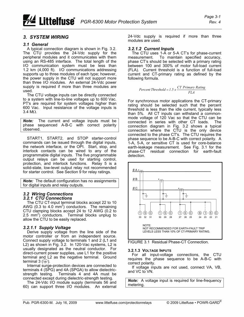
24-Vdc supply is required if more than three modules are used. 3.2.1.2 Current Inputs The CTU uses 1-A or 5-A CT’s for phase-current measurement. To maintain specified accuracy, phase CT’s should be selected with a primary rating between 100 and 300% of motor full-load current (FLA). Current threshold is a function of full-load current and CT-primary rating as defined by the following formula.
For synchronous motor applications the CT-primary rating should be selected such that the percent threshold is less than the idle current, typically less than 5%. All CT inputs can withstand a common-mode voltage of 120 Vac so that the CTU can be connected in series with other CT loads. The connection diagram in Fig. 3.2 shows a typical connection where the CTU is the only device connected to the phase CT's. The CTU requires the phase sequence to be A-B-C with correct polarity. A 1-A, 5-A, or sensitive CT is used for core-balance earth-leakage measurement. See Fig. 3.1 for the phase-CT residual connection for earth-fault detection.
FIGURE 3.1 Residual Phase-CT Connection. 3.2.1.3 VOLTAGE INPUTS For all input-voltage connections, the CTU requires the phase sequence to be A-B-C with correct polarity. If voltage inputs are not used, connect VA, VB, and VC to VN. Note: A voltage input is required for line-frequency metering.
FLARatingPrimary CT x 1.5 Threshold Percent =

Page 3-2 PGR-6300 Motor Protection System Rev. 4
Pub. PGR-6300-M. July 16, 2009 www.littelfuse.com/protectionrelays © 2009 Littelfuse • POWR-GARD®
0A
0B
0C
CO
NTA
CT
OR
K1
EA
RT
HFA
ULT
CT
ALT
ER
NA
TE
CO
NN
EC
TIO
NS
HO
WN
DO
TT
ED
ALT
ER
NA
TE
24
VD
CF
IELD
WIR
ING
OF
DIG
ITA
LIN
PU
TS
PH
AS
EC
T'S
DIR
EC
TV
OLT
AG
EIN
PU
T
MO
TO
R
NO
TE
1
PT
C
20
mA
AN
ALO
GIN
PU
T
L1
L1
L2
L2
K1
SO
LID
STA
TE
RE
LA
Y
TO
CO
MM
UN
ICA
TIO
NS
NE
TW
OR
K4-2
0m
AA
NA
LO
GO
UT
PU
T
CO
NTA
CT
OR
STA
TU
SC
ON
TA
CT
K1a
K1a
STA
RT
STA
RT
ST
OP
ST
OP
S1
S1
S2
S2
S3
S3
S4
S4
TA
CH
INP
UT
OP
ER
AT
OR
INT
ER
FA
CE
RE
AR
VIE
W
LO
WE
RT
ER
MIN
ALS
UP
PE
RT
ER
MIN
ALS
NO
TE
S:
1.
SE
EF
IGS
.3.8
AN
D3.9
FO
RR
TD
CO
NN
EC
TIO
NS
.
+-
+-
I N 1
I N 2
I N 3
I N 4
I N 5
I N 6
I N 7
H S I
C O M
24
VD
CS
OU
RC
ED
IGIT
AL
INP
UT
S
41
43
45
47
49
51
42
44
46
48
50
13
52
4
0 V
+ 2 4 V
S H L D
RE
LA
YO
UT
PU
TS
12
34
5
56
87
911
10
12
14
13
15
16
L 1L 2
S P G
S P G A1
24
4A
3PH
AS
EC
UR
RE
NT
VO
LTA
GE
V NV A
V BV C
5A
5A
5A
5A
1A
1A
1A
1A
AB
C
33 1
11
1S
32 5
55
5
31 C
CC
C
30
29
28
27
26
25
20
19
18
17
EA
RT
HLE
AK
AG
E
EF
CT
24
23
22
21
++
PO
WE
R
TR
IP
ALA
RM
ER
RO
R
RE
SE
T
MO
TO
RPRO
TEC
TIO
NSY
STEM
CO
NTRO
LU
NIT
PG
R-6
300
SERIE
SPG
R-6
300
SERIE
S
62
PO
WR-G
ARD
61
60
59
58
57
56
55
54
53
52
IRIG
2 4 V
S H
0 V
CO
MM
I/O
MO
DU
LE
PTC
AN
IN
OPERA
TO
R
INTERFA
CE
35
36
37
39
40
S H
CO
MM
AN
OU
T
41
42
43
44
45
46
47
48
49
50
51
24
VD
C
SO
URC
E
DIG
ITA
LIN
PU
TS
C O M
I N 1
I N 2
I N 3
I N 4
I N 5
I N 6
I N 7
H S I
FIGURE 3.2 Typical PGR-6300 Connection Diagram.
Page 3-3 PGR-6300 Motor Protection System Rev. 4
Pub. PGR-6300-M. July 16, 2009 www.littelfuse.com/protectionrelays © 2009 Littelfuse • POWR-GARD®
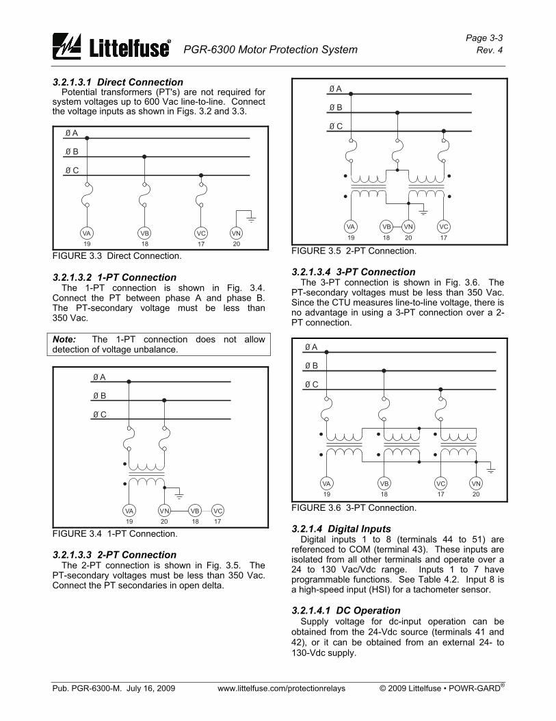
3.2.1.3.1 Direct Connection Potential transformers (PT's) are not required for system voltages up to 600 Vac line-to-line. Connect the voltage inputs as shown in Figs. 3.2 and 3.3.
0 A
0 B
0 C
VA VB VC VN
19 18 17 20 FIGURE 3.3 Direct Connection. 3.2.1.3.2 1-PT Connection The 1-PT connection is shown in Fig. 3.4. Connect the PT between phase A and phase B. The PT-secondary voltage must be less than 350 Vac. Note: The 1-PT connection does not allow detection of voltage unbalance.
0 A
0 B
0 C
VNVA VCVB
19 20 18 17 FIGURE 3.4 1-PT Connection. 3.2.1.3.3 2-PT Connection The 2-PT connection is shown in Fig. 3.5. The PT-secondary voltages must be less than 350 Vac. Connect the PT secondaries in open delta.
0 A
0 B
0 C
VA VCVB VN
17201819 FIGURE 3.5 2-PT Connection. 3.2.1.3.4 3-PT Connection The 3-PT connection is shown in Fig. 3.6. The PT-secondary voltages must be less than 350 Vac. Since the CTU measures line-to-line voltage, there is no advantage in using a 3-PT connection over a 2-PT connection.
0 A
0 B
0 C
VA VB VC VN
19 18 17 20 FIGURE 3.6 3-PT Connection. 3.2.1.4 Digital Inputs Digital inputs 1 to 8 (terminals 44 to 51) are referenced to COM (terminal 43). These inputs are isolated from all other terminals and operate over a 24 to 130 Vac/Vdc range. Inputs 1 to 7 have programmable functions. See Table 4.2. Input 8 is a high-speed input (HSI) for a tachometer sensor. 3.2.1.4.1 DC Operation Supply voltage for dc-input operation can be obtained from the 24-Vdc source (terminals 41 and 42), or it can be obtained from an external 24- to 130-Vdc supply.

Page 3-4 PGR-6300 Motor Protection System Rev. 4
Pub. PGR-6300-M. July 16, 2009 www.littelfuse.com/protectionrelays © 2009 Littelfuse • POWR-GARD®
The internal source is current limited at 100 mA and is referenced to the analog output (terminal 40) and the I/O Supply (terminal 56). Connect the “−” terminal of the dc source to COM and connect field inputs between “+” and the digital-input terminals. 3.2.1.4.2 AC Operation Inputs operate over a 24- to 130-Vac range. Connect the ac neutral to COM and connect field inputs between line and the digital inputs. 3.2.1.4.3 Combined AC and DC Operation If both ac and dc inputs are used, connect both the ac-supply common and dc-supply “−” to COM. 3.2.1.4.4 Tachometer Input (HSI) A tachometer sensor can be used to provide motor-speed measurement. Connect a logic-output PNP tachometer as shown in Fig. 3.7.
24 VDCSOURCE
DIGITALINPUTS
PNP TACHOMETERSENSOR
+24
41
42
51
43
HSI
COM
–
+
FIGURE 3.7 Digital Tachometer Input (HSI). 3.2.1.5 Analog Input (AN IN) The analog input (terminal 52 and 53) is a 4–20-mA current input with a 100-Ω input impedance. Note: The analog input is referenced to an internal supply with 100-kΩ resistors. Maximum common-mode voltage is ± 5 Vdc with respect to CTU terminal 4. 3.2.1.6 Analog Output (AN OUT) The analog output is a self-powered current-source output. The current source output is the “+” (terminal 39) and the common is “−” (terminal 40). Note: The analog output (terminal 40) is internally referenced to the 24-Vdc source (terminal 42) and the I/O supply (terminal 56). 3.2.1.7 PTC Input Terminals 54 and 55 are provided for PTC over-temperature protection. See Section 9 for specifications.
3.2.1.8 IRIG-B Input Terminals 61 and 62 are used for an IRIG-B time-code signal. When an IRIG-B signal is detected, the real-time clock (RTC) synchronizes with it. The user must set the PGR-6300 date value because the IRIG-B day-of-the-year parameter is not supported. If the time-code generator does not have a local-time adjustment, the IRIG Offset set points can be used to adjust the hour and minute values so that the PGR-6300 will read local time. 3.2.1.9 I/O Module Communication The I/O module communications interface (terminals 56 through 60) is used to support optional modules. The connector labeled Operator Interface on the CTU top panel is in parallel with terminals 50 to 56. It is used for direct OPI mounting. See Section 2.3. I/O module communication is based on the two-wire multi-drop RS-485 standard. Overall line length must not exceed 1.2 km (4,000 ft). For line lengths exceeding 10 m (33 ft), 150-Ω terminations are required at the cable ends. See Fig. 3.9. 3.2.1.10 RS-485 Network Communications Terminals 35, 36, and 37 are used for the standard RS-485 interface. See Section 4.2.15. 3.2.2 OPI Connections and Address Selection Connect the OPI to the CTU using shielded cable (Belden® 3124A or equivalent). The 24-Vdc supply for the OPI is provided by the CTU. The cable shield must be connected at both ends so that OPI transient protection is operational. See Fig. 3.9. The OPI has two switches to select its network address. See Figs. 2.2 and 3.8. Up to three OPI modules can be connected to the I/O MODULE bus, and each active OPI must have a unique address. If one OPI is used, address 1 must be used. If two OPI's are used, addresses 1 and 2 must be used. If three OPI's are used, addresses 1, 2, and 3 must be used. Table 3.1 and Fig. 3.8 shows the addressing selection format.
TABLE 3.1 OPI Address Selection ADDRESS SWITCH 1 SWITCH 2
0 (Factory test) Open Open
1 (First OPI) Closed Open
2 (Second OPI) Open Closed
3 (Third OPI) Closed Closed
Page 3-5 PGR-6300 Motor Protection System Rev. 4
Pub. PGR-6300-M. July 16, 2009 www.littelfuse.com/protectionrelays © 2009 Littelfuse • POWR-GARD®
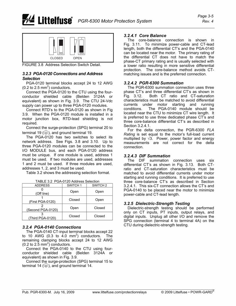
1 2
OPEN OPEN
CLOSED OPEN
FIGURE 3.8 Address Selection Switch Detail. 3.2.3 PGA-0120 Connections and Address Selection PGA-0120 terminal blocks accept 24 to 12 AWG (0.2 to 2.5 mm2) conductors. Connect the PGA-0120 to the CTU using the four-conductor shielded cable (Belden 3124A or equivalent) as shown in Fig. 3.9. The CTU 24-Vdc supply can power up to three PGA-0120 modules. Connect RTD’s to the PGA-0120 as shown in Fig 3.9. When the PGA-0120 module is installed in a motor junction box, RTD-lead shielding is not required. Connect the surge-protection (SPG) terminal 20 to terminal 19 ( ), and ground terminal 19. The PGA-0120 has two switches to select its network address. See Figs. 3.8 and 3.10. Up to three PGA-0120 modules can be connected to the I/O MODULE bus, and each PGA-0120 address must be unique. If one module is used, address 1 must be used. If two modules are used, addresses 1 and 2 must be used. If three modules are used, addresses 1, 2, and 3 must be used. Table 3.2 shows the addressing selection format.
TABLE 3.2 PGA-0120 Address Selection ADDRESS SWITCH 1 SWITCH 2
0 (Off line) Open Open
1 (First PGA-0120) Closed Open
2 (Second PGA-0120) Open Closed
3 (Third PGA-0120) Closed Closed
3.2.4 PGA-0140 Connections The PGA-0140 CT-input terminal blocks accept 22 to 10 AWG (0.3 to 4.0 mm2) conductors. The remaining clamping blocks accept 24 to 12 AWG (0.2 to 2.5 mm2) conductors. Connect the PGA-0140 to the CTU using four-conductor shielded cable (Belden 3124A or equivalent) as shown in Fig. 3.9. Connect the surge-protection (SPG) terminal 15 to terminal 14 ( ), and ground terminal 14.
3.2.4.1 Core Balance The core-balance connection is shown in Fig. 3.11. To minimize power-cable and CT-lead length, both the differential CT’s and the PGA-0140 can be located near the motor. The primary rating of the differential CT does not have to match the phase-CT primary rating and is usually selected with a lower ratio resulting in more sensitive differential protection. The core-balance method avoids CT-matching issues and is the preferred connection. 3.2.4.2 PGR-6300 Summation The PGR-6300 summation connection uses three phase CT’s and three differential CT’s as shown in Fig. 3.12. Both CT ratio and CT-saturation characteristics must be matched to avoid differential currents under motor starting and running conditions. The PGA-0140 module should be located near the CTU to minimize CT wire length. It is preferred to use three dedicated phase CT’s and three core-balance differential CT’s as described in Section 3.2.4.1. For the delta connection, the PGR-6300 FLA Rating is set equal to the motor’s full-load current multiplied by √3. Power, power factor and energy measurements are not correct for the delta connection. 3.2.4.3 DIF Summation The DIF summation connection uses six differential CT’s as shown in Fig. 3.13. Both CT-ratio and CT-saturation characteristics must be matched to avoid differential currents under motor starting and running conditions. It is preferred to use three core-balance CT’s as described in Section 3.2.4.1. This six-CT connection allows the CT’s and PGA-0140 to be placed near the motor to minimize power-cable and CT-lead length. 3.2.5 Dielectric-Strength Testing Dielectric-strength testing should be performed only on CT inputs, PT inputs, output relays, and digital inputs. Unplug all other I/O and remove the SPG connection (terminal 4 to terminal 4A) on the CTU during dielectric-strength testing.

Page 3-6 PGR-6300 Motor Protection System Rev. 4
Pub. PGR-6300-M. July 16, 2009 www.littelfuse.com/protectionrelays © 2009 Littelfuse • POWR-GARD®
CONTROL UNITOPERATORINTERFACE
PGR-6300PGR-6300
3
CONTROL UNITOPERATORINTERFACE
TEMPERATUREINPUT
MODULE
TEMPERATUREINPUT
MODULE
TEMPERATUREINPUT
MODULE
TEMPERATUREINPUT
MODULE
16
17
11
11
15
18
16
17
15
18
11
11
18
15
2
2
3
3
1
1
17
16
18
15
17
16
4
4
5
5
+
-
+
-
+
+
+
+
-
+
-
+
-
-
-
-
PGR-6300
PGA-0120
PGA-0120
PGA-0120
PGA-0120
PGR-6300
a)
b)
59
59
60
60
57
57
58
58
56
56
3
19
19
1919
19
R
R
t
t
R t
R t
INTERCONNECT CABLE BELDEN 3124AOR EQUIVALENT.
R
CONNECT CABLE SHIELD ON BOTH ENDSFOR OPI INSTALLATIONS.
= 150 OHMS, 1/4 WATT. REQUIRED FOR LINELENGTHS EXCEEDING 10 M (33 FT).
t
NOTES:
1.
2.
3.
RED
RED
RED
BLACK
GREEN
GREEN
GREEN
WHITE
WHITE
WHITE
WHITE
GREEN
BLACK
BLACK
BLACK
RED
FIGURE 3.9 Two Examples of I/O Module Connections.
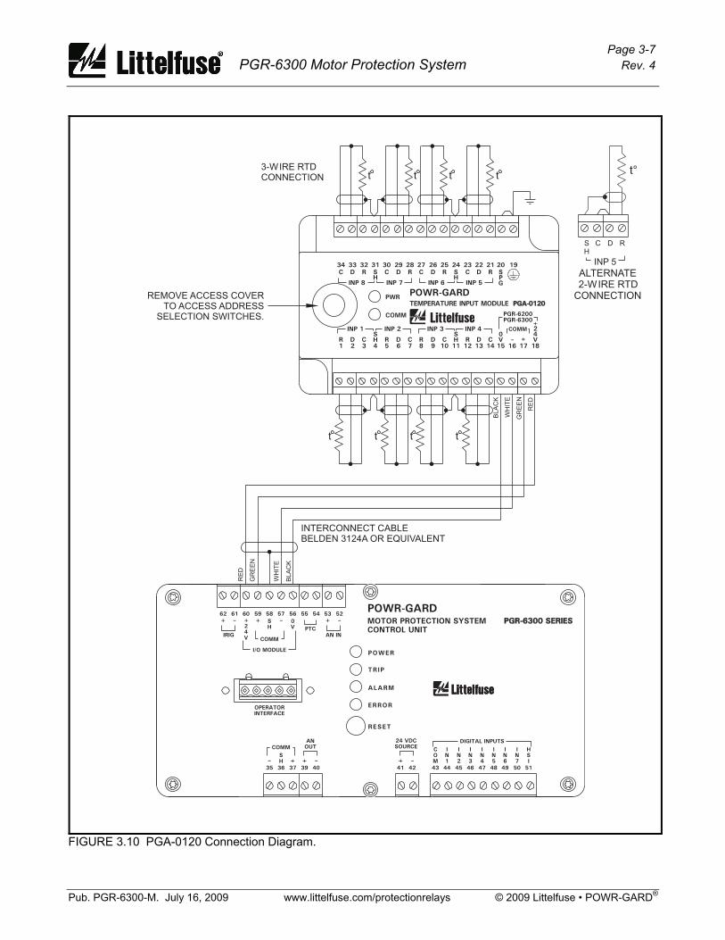
Page 3-7 PGR-6300 Motor Protection System Rev. 4
Pub. PGR-6300-M. July 16, 2009 www.littelfuse.com/protectionrelays © 2009 Littelfuse • POWR-GARD®
3-WIRE RTDCONNECTION
INTERCONNECT CABLEBELDEN 3124A OR EQUIVALENT
t
t
t
t t
t
t
t
RE
D
GR
EE
N
WH
ITE
BL
AC
K
BL
AC
K
WH
ITE
GR
EE
N
RE
D
RDC
INP 5
ALTERNATE2-WIRE RTD
CONNECTION
SH
t°
REMOVE ACCESS COVERTO ACCESS ADDRESS
SELECTION SWITCHES. PGR-6200
PGR-6300
POWR-GARD
TEMPERATURE INPUT MODULE PGA-0120PGA-0120
PWR
COMM
31
SH
24V
COMM
0V
INP 8 INP 7 INP 6 INP 5
INP 1 INP 2 INP 3 INP 4
34 33 32 30 29 28 27 26 25 24 23 22 21 20 19
SPG
C D R C D R C D R C D RSH
1 2 3 4 5 6 7 8 9 10 11 12 13 14
R D C R D C R D C R D CSH
SH
15 16 17 18
++
POWER
TRIP
ALARM
ERROR
RESET
MOTOR PROTECTION SYSTEM
CONTROL UNIT
PGR-6300 SERIESPGR-6300 SERIES
62POWR-GARD
61 60 59 58 57 56 55 54 53 52
IRIG
2
4
V
S
H
0
V
COMM
I/O MODULE
PTC
AN IN
OPERATOR
INTERFACE
35 36 37 39 40
S
H
COMM
AN
OUT
41 42 43 44 45 46 47 48 49 50 51
24 VDC
SOURCE
DIGITAL INPUTS
C
O
M
I
N
1
I
N
2
I
N
3
I
N
4
I
N
5
I
N
6
I
N
7
H
S
I
FIGURE 3.10 PGA-0120 Connection Diagram.
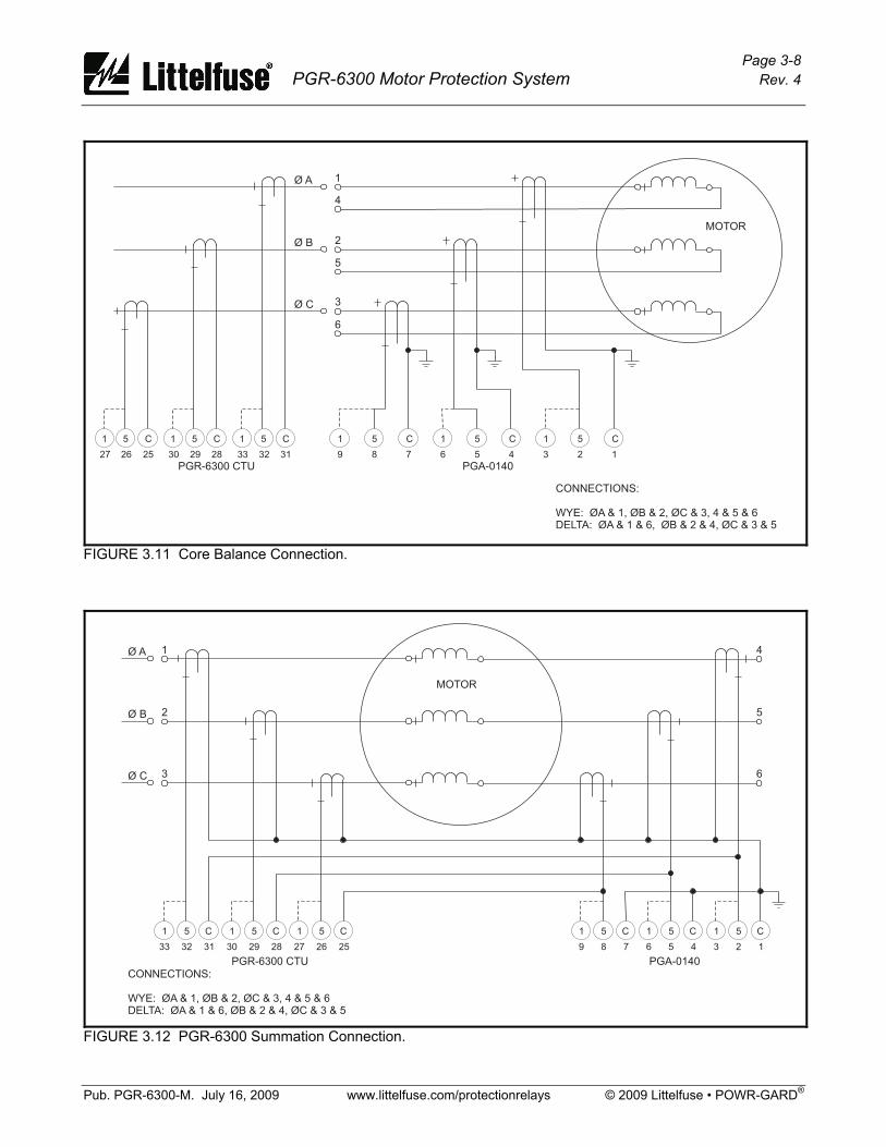
Page 3-8 PGR-6300 Motor Protection System Rev. 4
Pub. PGR-6300-M. July 16, 2009 www.littelfuse.com/protectionrelays © 2009 Littelfuse • POWR-GARD®
C 1 5 C 1 5 C51
7 6 5 4 3 2 189
MOTOR
PGR-6300 CTU
1
4
2
5
3
6
Ø A
Ø B
Ø C
C 1 5 C 1 5 C5
25 30 29 28 33 32 3126
1
27
PGA-0140
CONNECTIONS:
WYE: ØA & 1, ØB & 2, ØC & 3, 4 & 5 & 6DELTA: ØA & 1 & 6, ØB & 2 & 4, ØC & 3 & 5
FIGURE 3.11 Core Balance Connection.
C51
313233
C51
282930
C51
252627
C51
789
C51
456
C51
123
PGA-0140PGR-6300 CTU
MOTOR
1
2
3
Ø A
Ø B
Ø C
4
5
6
CONNECTIONS:
WYE: ØA & 1, ØB & 2, ØC & 3, 4 & 5 & 6DELTA: ØA & 1 & 6, ØB & 2 & 4, ØC & 3 & 5
FIGURE 3.12 PGR-6300 Summation Connection.

Page 3-9 PGR-6300 Motor Protection System Rev. 4
Pub. PGR-6300-M. July 16, 2009 www.littelfuse.com/protectionrelays © 2009 Littelfuse • POWR-GARD®
C51
789
C51
456
C51
123
PGA-0140
MOTOR
1
2
3
4
5
6
CONNECTIONS:
WYE: ØA & 1, ØB & 2, ØC & 3, 4 & 5 & 6DELTA: ØA & 1 & 6, ØB & 2 & 4, ØC & 3 & 5
PGR-6300 CTU
Ø A
Ø B
Ø C
C 1 5 C 1 5 C5
25 30 29 28 33 32 3126
1
27
FIGURE 3.13 DIF Summation Connection.

Page 3-10 PGR-6300 Motor Protection System Rev. 4
Pub. PGR-6300-M. July 16, 2009 www.littelfuse.com/protectionrelays © 2009 Littelfuse • POWR-GARD®
This page intentionally left blank.
Page 4-1 PGR-6300 Motor Protection System Rev. 4
Pub. PGR-6300-M. July 16, 2009 www.littelfuse.com/protectionrelays © 2009 Littelfuse • POWR-GARD®
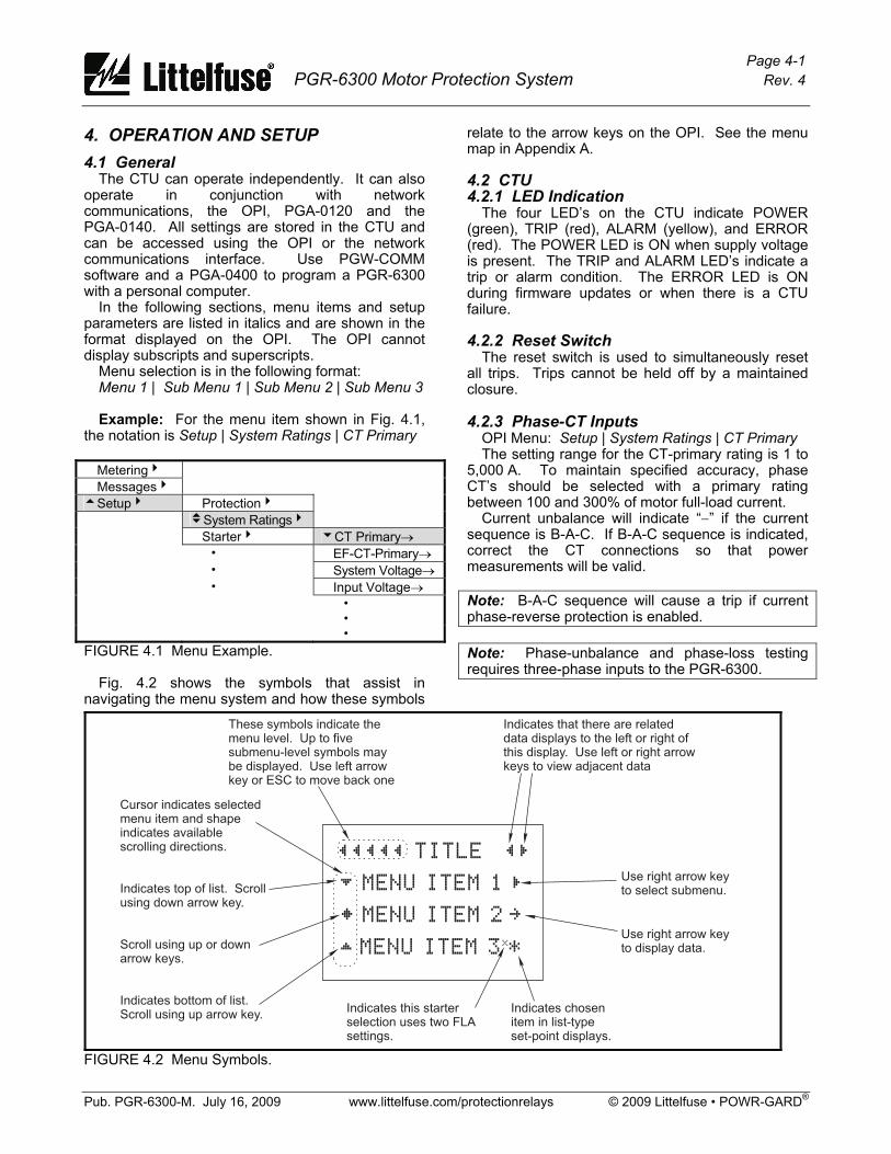
4. OPERATION AND SETUP 4.1 General The CTU can operate independently. It can also operate in conjunction with network communications, the OPI, PGA-0120 and the PGA-0140. All settings are stored in the CTU and can be accessed using the OPI or the network communications interface. Use PGW-COMM software and a PGA-0400 to program a PGR-6300 with a personal computer. In the following sections, menu items and setup parameters are listed in italics and are shown in the format displayed on the OPI. The OPI cannot display subscripts and superscripts. Menu selection is in the following format: Menu 1 | Sub Menu 1 | Sub Menu 2 | Sub Menu 3 Example: For the menu item shown in Fig. 4.1, the notation is Setup | System Ratings | CT Primary
Metering4 Messages4 5Setup4 Protection4 vSystem Ratings4 Starter4 6CT Primary→ • EF-CT-Primary→ • System Voltage→ • Input Voltage→ • • • FIGURE 4.1 Menu Example. Fig. 4.2 shows the symbols that assist in navigating the menu system and how these symbols
relate to the arrow keys on the OPI. See the menu map in Appendix A. 4.2 CTU 4.2.1 LED Indication The four LED’s on the CTU indicate POWER (green), TRIP (red), ALARM (yellow), and ERROR (red). The POWER LED is ON when supply voltage is present. The TRIP and ALARM LED’s indicate a trip or alarm condition. The ERROR LED is ON during firmware updates or when there is a CTU failure. 4.2.2 Reset Switch The reset switch is used to simultaneously reset all trips. Trips cannot be held off by a maintained closure. 4.2.3 Phase-CT Inputs OPI Menu: Setup | System Ratings | CT Primary The setting range for the CT-primary rating is 1 to 5,000 A. To maintain specified accuracy, phase CT’s should be selected with a primary rating between 100 and 300% of motor full-load current. Current unbalance will indicate “−” if the current sequence is B-A-C. If B-A-C sequence is indicated, correct the CT connections so that power measurements will be valid. Note: B-A-C sequence will cause a trip if current phase-reverse protection is enabled. Note: Phase-unbalance and phase-loss testing requires three-phase inputs to the PGR-6300.
¬¬¬¬¬ TITLE ¬Ñ
½ MENU ITEM 1 Ñ
² MENU ITEM 2 ¼
« MENU ITEM 3 *x
These symbols indicate themenu level. Up to fivesubmenu-level symbols maybe displayed. Use left arrowkey or ESC to move back one
Indicates that there are relateddata displays to the left or right ofthis display. Use left or right arrowkeys to view adjacent data
Use right arrow keyto select submenu.
Use right arrow keyto display data.
Indicates chosenitem in list-typeset-point displays.
Indicates this starterselection uses two FLAsettings.
Cursor indicates selectedmenu item and shapeindicates availablescrolling directions.
Indicates top of list. Scrollusing down arrow key.
Scroll using up or downarrow keys.
Indicates bottom of list.Scroll using up arrow key.
FIGURE 4.2 Menu Symbols.
Page 4-2 PGR-6300 Motor Protection System Rev. 4
Pub. PGR-6300-M. July 16, 2009 www.littelfuse.com/protectionrelays © 2009 Littelfuse • POWR-GARD®
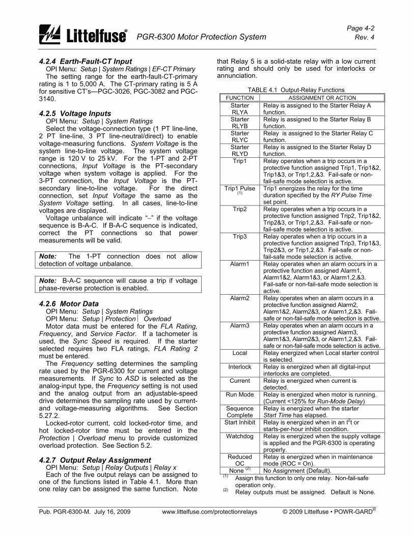
4.2.4 Earth-Fault-CT Input OPI Menu: Setup | System Ratings | EF-CT Primary The setting range for the earth-fault-CT-primary rating is 1 to 5,000 A. The CT-primary rating is 5 A for sensitive CT’s—PGC-3026, PGC-3082 and PGC-3140. 4.2.5 Voltage Inputs OPI Menu: Setup | System Ratings Select the voltage-connection type (1 PT line-line, 2 PT line-line, 3 PT line-neutral/direct) to enable voltage-measuring functions. System Voltage is the system line-to-line voltage. The system voltage range is 120 V to 25 kV. For the 1-PT and 2-PT connections, Input Voltage is the PT-secondary voltage when system voltage is applied. For the 3-PT connection, the Input Voltage is the PT-secondary line-to-line voltage. For the direct connection, set Input Voltage the same as the System Voltage setting. In all cases, line-to-line voltages are displayed. Voltage unbalance will indicate “−” if the voltage sequence is B-A-C. If B-A-C sequence is indicated, correct the PT connections so that power measurements will be valid. Note: The 1-PT connection does not allow detection of voltage unbalance. Note: B-A-C sequence will cause a trip if voltage phase-reverse protection is enabled. 4.2.6 Motor Data OPI Menu: Setup | System Ratings OPI Menu: Setup | Protection ⏐ Overload Motor data must be entered for the FLA Rating, Frequency, and Service Factor. If a tachometer is used, the Sync Speed is required. If the starter selected requires two FLA ratings, FLA Rating 2 must be entered. The Frequency setting determines the sampling rate used by the PGR-6300 for current and voltage measurements. If Sync to ASD is selected as the analog-input type, the Frequency setting is not used and the analog output from an adjustable-speed drive determines the sampling rate used by current- and voltage-measuring algorithms. See Section 5.27.2. Locked-rotor current, cold locked-rotor time, and hot locked-rotor time must be entered in the Protection | Overload menu to provide customized overload protection. See Section 5.2. 4.2.7 Output Relay Assignment OPI Menu: Setup | Relay Outputs | Relay x Each of the five output relays can be assigned to one of the functions listed in Table 4.1. More than one relay can be assigned the same function. Note
that Relay 5 is a solid-state relay with a low current rating and should only be used for interlocks or annunciation.
TABLE 4.1 Output-Relay Functions FUNCTION ASSIGNMENT OR ACTION
Starter RLYA
Relay is assigned to the Starter Relay A function.
Starter RLYB
Relay is assigned to the Starter Relay B function.
Starter RLYC
Relay is assigned to the Starter Relay C function.
Starter RLYD
Relay is assigned to the Starter Relay D function.
Trip1 Relay operates when a trip occurs in a protective function assigned Trip1, Trip1&2, Trip1&3, or Trip1,2,&3. Fail-safe or non-fail-safe mode selection is active.
Trip1 Pulse (1)
Trip1 energizes the relay for the time duration specified by the RY Pulse Time set point.
Trip2 Relay operates when a trip occurs in a protective function assigned Trip2, Trip1&2, Trip2&3, or Trip1,2,&3. Fail-safe or non-fail-safe mode selection is active.
Trip3 Relay operates when a trip occurs in a protective function assigned Trip3, Trip1&3, Trip2&3, or Trip1,2,&3. Fail-safe or non-fail-safe mode selection is active.
Alarm1 Relay operates when an alarm occurs in a protective function assigned Alarm1, Alarm1&2, Alarm1&3, or Alarm1,2,&3. Fail-safe or non-fail-safe mode selection is active.
Alarm2 Relay operates when an alarm occurs in a protective function assigned Alarm2, Alarm1&2, Alarm2&3, or Alarm1,2,&3. Fail-safe or non-fail-safe mode selection is active.
Alarm3 Relay operates when an alarm occurs in a protective function assigned Alarm3, Alarm1&3, Alarm2&3, or Alarm1,2,&3. Fail-safe or non-fail-safe mode selection is active.
Local Relay energized when Local starter control is selected.
Interlock Relay is energized when all digital-input interlocks are completed.
Current Relay is energized when current is detected.
Run Mode Relay is energized when motor is running. (Current <125% for Run-Mode Delay)
Sequence Complete
Relay is energized when the starter Start Time has elapsed.
Start Inhibit Relay is energized when in an I2t or starts-per-hour inhibit condition.
Watchdog Relay is energized when the supply voltage is applied and the PGR-6300 is operating properly.
Reduced OC
Relay is energized when in maintenance mode (ROC = On).
None (2) No Assignment (Default). (1) Assign this function to only one relay. Non-fail-safe operation only. (2) Relay outputs must be assigned. Default is None.
Page 4-3 PGR-6300 Motor Protection System Rev. 4
Pub. PGR-6300-M. July 16, 2009 www.littelfuse.com/protectionrelays © 2009 Littelfuse • POWR-GARD®
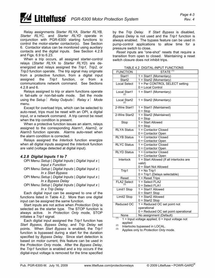
Relay assignments Starter RLYA, Starter RLYB, Starter RLYC, and Starter RLYD operate in conjunction with PGR-6300 starting functions to control the motor-starter contactor(s). See Section 6. Contactor status can be monitored using auxiliary contacts and the digital inputs. See Section 4.2.8 and Figs. 6.9 to 6.23. When a trip occurs, all assigned starter-control relays (Starter RLYA to Starter RLYD) are de-energized and relays assigned the Trip1, Trip2, or Trip3 function operate. The trip signal may originate from a protective function, from a digital input assigned the Trip1 function, or from a communications network command. See Sections 4.2.8 and 6. Relays assigned to trip or alarm functions operate in fail-safe or non-fail-safe mode. Set the mode using the Setup ⏐ Relay Outputs ⏐ Relay x ⏐ Mode menu. Except for overload trips, which can be selected to auto-reset, trips must be reset with an OPI, a digital input, or a network command. A trip cannot be reset when the trip condition is present. When a protective function issues an alarm, relays assigned to the corresponding Alarm1, Alarm2, or Alarm3 function operate. Alarms auto-reset when the alarm condition is corrected. Relays assigned the Interlock function energize when all digital inputs assigned the Interlock function are valid (voltage detected at digital input). 4.2.8 Digital Inputs 1 to 7 OPI Menu: Setup | Digital Inputs | Digital Input x |
Input x Function OPI Menu: Setup | Digital Inputs | Digital Input x | In x Start Bypass OPI Menu: Setup | Digital Inputs | Digital Input x | In x Bypass Delay OPI Menu: Setup | Digital Inputs | Digital Input x | In x Trip Delay Each digital input can be assigned to one of the functions listed in Table 4.2. More than one digital input can be assigned the same function. Start inputs are not active when Protection Only is selected as the starter type. The STOP function is always active. In Protection Only mode, STOP initiates a Trip1 signal. Each digital input assigned the Trip1 function has Start Bypass, Bypass Delay, and Trip Delay set points. When Start Bypass is enabled, the Trip1 function is bypassed during a start for the duration specified by Bypass Delay. Since start detection is based on motor current, this feature can be used in the Protection Only mode. After the Bypass Delay, the Trip1 function is enabled and a trip occurs if the digital-input voltage is removed for the time specified
by the Trip Delay. If Start Bypass is disabled, Bypass Delay is not used and the Trip1 function is always enabled. The bypass feature can be used in pump-control applications to allow time for a pressure switch to close. Reset inputs are “one-shot” resets that require a transition from open to closed. Maintaining a reset switch closure does not inhibit trips.
TABLE 4.2 DIGITAL-INPUT FUNCTIONS FUNCTION STATE (1)
Start1 1 = Start1 (Momentary) Start2 1 = Start2 (Momentary)
Local Select 1 = Per CONTROL SELECT setting 0 = Local Control
Local Start1 (2)
1 = Start1 (Momentary)
Local Start2 (2)
1 = Start2 (Momentary)
2-Wire Start1 1 = Start1 (Maintained) 0 = Stop
2-Wire Start2 1 = Start2 (Maintained) 0 = Stop
Stop 1 = Start Allowed 0 = Stop
RLYA Status 1 = Contactor Closed 0 = Contactor Open
RLYB Status 1 = Contactor Closed 0 = Contactor Open
RLYC Status 1 = Contactor Closed 0 = Contactor Open
RLYD Status 1 = Contactor Closed 0 = Contactor Open
Interlock 1 = Start Allowed (If all interlocks are valid) 0 = Start Not Allowed
Trip1 1 = No Trip1 0 = Trip1 (Delays selectable)
Reset 1 = Reset Trips FLA2 Select
(3) 1 = Select FLA2 0 = Select FLA1
Limit1 Stop 1 = Start1 Allowed 0 = Start1 Stop
Limit2 Stop 1 = Start2 Allowed 0 = Start2 Stop
Reduced OC 1 = Reduced OC set point not operational 0 = Reduced OC set point operational
None No assignment (Default) (1) 1 = Input voltage applied, 0 = Input voltage not
applied (2) Interlocks bypassed in LOCAL. (3) Applies only to Protection Only mode.
Page 4-4 PGR-6300 Motor Protection System Rev. 4
Pub. PGR-6300-M. July 16, 2009 www.littelfuse.com/protectionrelays © 2009 Littelfuse • POWR-GARD®
LOCAL is selected using the OPI, the digital input, or by network communications. The Local Select source is responsible for de-selecting. For example if both the digital input and the network communications select LOCAL, both must also de-select LOCAL. In applications where PGR-6300 starter functions are not used, FLA2 Select can be used to switch between FLA1 and FLA2. This applies only to Protection Only mode. The selected FLA is displayed in the Metering ⏐ System State menu. Limit1 Stop and Limit2 Stop are limit-switch inputs typically used with reversing starters. Limit1 Stop is a stop input associated with Start1 and Limit2 Stop is a stop input associated with Start2. The Reduced OC selection operates in conjunction with the reduced overcurrent set point which must be enabled. See Section 5.5. When Reduced OC is selected and no digital input voltage is applied, the reduced overcurrent set point is operational. When digital input voltage is applied, the reduced overcurrent set point is not operational. The following rules apply when multiple inputs are assigned the same function: • Start1, Start2, Local Start1, and Local Start2:
Momentary voltage on any input will initiate a start. (PGR-6300 must be in LOCAL for Local Start1 and Local Start2 operation.)
• Stop: Voltage must be present on all inputs to allow a PGR-6300-controlled start.
• Interlock: Voltage must be present on all inputs to allow a PGR-6300-controlled start and to energize an interlock output relay. Digital inputs programmed as Interlock are bypassed in LOCAL.
• RLYA, RLYB, RLYC, and RLYD Status: Voltage applied to any input programmed for a contactor status results in contactor-closed status.
• Reset: Voltage applied to any input will reset trips.
• 2-Wire Start1 and 2-Wire Start2: Voltage on any input will initiate a start. All inputs must be open for a stop.
• FLA2 Select: Voltage on one or more inputs assigned to FLA2 Select will select FLA2.
4.2.9 Tachometer Input (HSI) OPI Menu: Setup | System Ratings | Sync Speed OPI Menu: Setup | Digital Inputs | Tachometer This input is provided for connection to a 24-Vdc proximity sensor for speed measurement. Set the number of pulses per revolution and enable the High-Speed Input in the Tachometer menu. Pulse-frequency range is 10 Hz to 10 kHz. These two settings are required for RPM readings. If Failure to Accelerate protection is used, set the motor’s synchronous speed in the Sync Speed
menu. To fully utilize a speed-setting range from 10 to 100%, a full-speed frequency of at least 100 Hz is required. The PGR-6300 averages 16 pulse periods to determine speed. 4.2.10 Analog Output OPI Menu: Setup | Analog Output | Output Parameter A 25-mA programmable current output is provided on the CTU. Analog-output parameters are shown in Table 4.3. Factory calibration is 4–20 mA. If calibration is required, use the Analog Output menus. Zero Calibration: • Select Zero in the Output Parameter menu. • Measure the output current and adjust the Zero
Calibrate setting for the desired output. The calibration number for 4 mA will be in the range of 100 to 110.
Full-Scale Calibration: • Select Full Scale in the Output Parameter menu. • Measure the output current and adjust the
FS Calibrate setting for the desired output. The calibration number for 20 mA will be in the range of 540 to 550.
Calibration numbers are not changed when factory defaults are loaded. 4.2.11 Analog Input OPI Menu: Setup | 4-20 Analog In | Input Function The analog input function is selectable as Metering Only, Protection, Sync to ASD, or Motor Speed. 4.2.11.1 Metering Only OPI Menu: Setup | 4-20 Analog In ⏐ Metering Only When Metering Only is selected, an analog input does not affect PGR-6300 operation, but its value can be observed in the Metering menu. 4.2.11.2 Protection OPI Menu: Setup | 4-20 Analog In ⏐ Protection The Protection analog input has high- and low-level trip alarm set points. A high-level trip or alarm occurs when the 4-20-mA input exceeds the high-level trip or alarm set point. A low-level trip or alarm occurs when the 4-20-mA input is lower than the low-level trip or alarm set point.
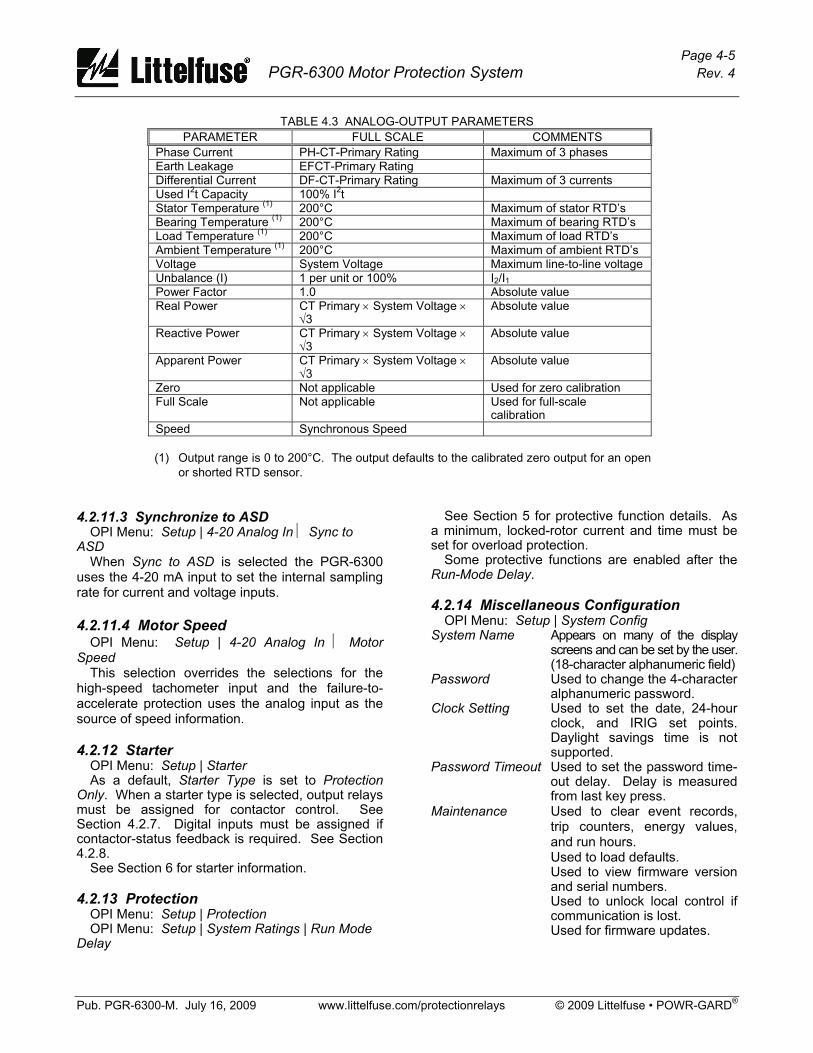
Page 4-5 PGR-6300 Motor Protection System Rev. 4
Pub. PGR-6300-M. July 16, 2009 www.littelfuse.com/protectionrelays © 2009 Littelfuse • POWR-GARD®
TABLE 4.3 ANALOG-OUTPUT PARAMETERS PARAMETER FULL SCALE COMMENTS
Phase Current PH-CT-Primary Rating Maximum of 3 phases Earth Leakage EFCT-Primary Rating Differential Current DF-CT-Primary Rating Maximum of 3 currents Used I2t Capacity 100% I2t Stator Temperature (1) 200°C Maximum of stator RTD’s Bearing Temperature (1) 200°C Maximum of bearing RTD’s Load Temperature (1) 200°C Maximum of load RTD’s Ambient Temperature (1) 200°C Maximum of ambient RTD’s Voltage System Voltage Maximum line-to-line voltage Unbalance (I) 1 per unit or 100% I2/I1 Power Factor 1.0 Absolute value Real Power CT Primary × System Voltage ×
√3 Absolute value
Reactive Power CT Primary × System Voltage × √3
Absolute value
Apparent Power CT Primary × System Voltage × √3
Absolute value
Zero Not applicable Used for zero calibration Full Scale Not applicable Used for full-scale
calibration Speed Synchronous Speed
(1) Output range is 0 to 200°C. The output defaults to the calibrated zero output for an open
or shorted RTD sensor.
4.2.11.3 Synchronize to ASD OPI Menu: Setup | 4-20 Analog In ⏐ Sync to ASD When Sync to ASD is selected the PGR-6300 uses the 4-20 mA input to set the internal sampling rate for current and voltage inputs. 4.2.11.4 Motor Speed OPI Menu: Setup | 4-20 Analog In ⏐ Motor Speed This selection overrides the selections for the high-speed tachometer input and the failure-to-accelerate protection uses the analog input as the source of speed information. 4.2.12 Starter OPI Menu: Setup | Starter As a default, Starter Type is set to Protection Only. When a starter type is selected, output relays must be assigned for contactor control. See Section 4.2.7. Digital inputs must be assigned if contactor-status feedback is required. See Section 4.2.8. See Section 6 for starter information. 4.2.13 Protection OPI Menu: Setup | Protection OPI Menu: Setup | System Ratings | Run Mode Delay
See Section 5 for protective function details. As a minimum, locked-rotor current and time must be set for overload protection. Some protective functions are enabled after the Run-Mode Delay. 4.2.14 Miscellaneous Configuration OPI Menu: Setup | System Config System Name Appears on many of the display
screens and can be set by the user. (18-character alphanumeric field)
Password Used to change the 4-character alphanumeric password.
Clock Setting Used to set the date, 24-hour clock, and IRIG set points. Daylight savings time is not supported.
Password Timeout Used to set the password time-out delay. Delay is measured from last key press.
Maintenance Used to clear event records, trip counters, energy values, and run hours.
Used to load defaults. Used to view firmware version
and serial numbers. Used to unlock local control if
communication is lost. Used for firmware updates.

Page 4-6 PGR-6300 Motor Protection System Rev. 4
Pub. PGR-6300-M. July 16, 2009 www.littelfuse.com/protectionrelays © 2009 Littelfuse • POWR-GARD®
4.2.15 Network Communications OPI Menu: Setup ⏐ Hardware ⏐ Network Comms The standard interface on the PGR-6300 is an RS-485 network. This network supports Modbus® RTU and A-B® DF1 protocols. The protocol, network ID (address), error checking, and baud rate are selectable. See Appendices C, D, E, and F. If equipped with an optional network interface, refer to the appropriate PGR-6300 optional communications interface manual. 4.3 OPI 4.3.1 General See Fig. 4.2. The Operator Interface (OPI) is used to perform motor-control functions, display meter readings, and program the CTU. Set points are not resident in the OPI. Control voltage for the OPI (24 Vdc) is supplied by the CTU and communications with the CTU is through an RS-485 link. This allows the OPI to be mounted up to 1.2 km (4,000’) from the CTU. Up to three OPI’s can be used with each CTU. 4.3.2 Configuring the CTU for OPI Operation OPI Menu: Setup | Hardware | OPI Display Select the number of OPI's in the Number of OPI's menu. The CTU supports up to three OPI’s. In multiple-OPI systems, all OPI's display the same information and the CTU will process key presses from all OPI's. If an OPI is not used, set number of OPI's to 1 (default). A loss-of-communication trip can be enabled in the OPI-Loss Trip menu. Display intensity can be set in the Intensity menu. To extend the life of the vacuum-florescent display, a screen saver is provided and enabled using the Screen Saver menu. The screen saver activation time is defined by the Setup | System Config | Password Timeout setting. 4.3.3 Starter Control OPI Menu: Setup | Starter | Starter Type OPI Menu: Setup | Hardware | OPI Display | OPI Ctrl Select A starter type other than Protection Only must be selected for starter functions to become operational. The OPI has a CONTROL SELECT key and three yellow LED’s (labeled REMOTE, OPI, and LOCAL) to select and indicate the start sources that the PGR-6300 will respond to. Each of the start sources can be enabled or disabled in the OPI Ctrl Select menu, and the CONTROL SELECT key allows the operator to choose from among the enabled start
sources. The factory default has all sources enabled and REMOTE selected. Regardless of the control setting, all stop sources are always enabled. 4.3.3.1 OPI Control If only the OPI LED is ON, the PGR-6300 is under OPI control and start keys on the OPI are the only start source the PGR-6300 will respond to. If the OPI has been enabled as a start source for remote control, the OPI LED will also be on when remote control is selected. In this case, the PGR-6300 will also respond to the other sources enabled in remote control. 4.3.3.2 Local Control OPI Menu: Setup | Digital Inputs | Digital Input x | Input x Function When the LOCAL LED is ON, the PGR-6300 is under local control and digital inputs programmed as Local Start 1 or Local Start 2 are the only start sources the PGR-6300 will respond to. Note: The I2t Start Inhibit function and digital inputs programmed as Interlock are bypassed in local control. Local control can also be selected with a network command or by a digital input programmed for Local Select—both have priority over the CONTROL SELECT key. If either or both methods force the PGR-6300 into local control and then release local control, the PGR-6300 will return to the previous control setting. Each local control source must release local control to allow the PGR-6300 to return to the previous control setting. 4.3.3.3 Remote Control OPI Menu: Setup | Starter | Remote Group When the REMOTE LED is ON, PGR-6300 start control is from the start sources enabled in the Remote Group menu. Start source selections are Digital Inputs, OPI, and Network. If Digital Inputs is enabled, digital inputs programmed for Start1, Start2, 2-Wire Start1, and 2-Wire Start2 are enabled. If OPI is enabled, the start keys on the OPI are enabled and if Network is enabled, start commands from the network are enabled. Note: The OPI STOP key and digital STOP inputs always cause a stop.
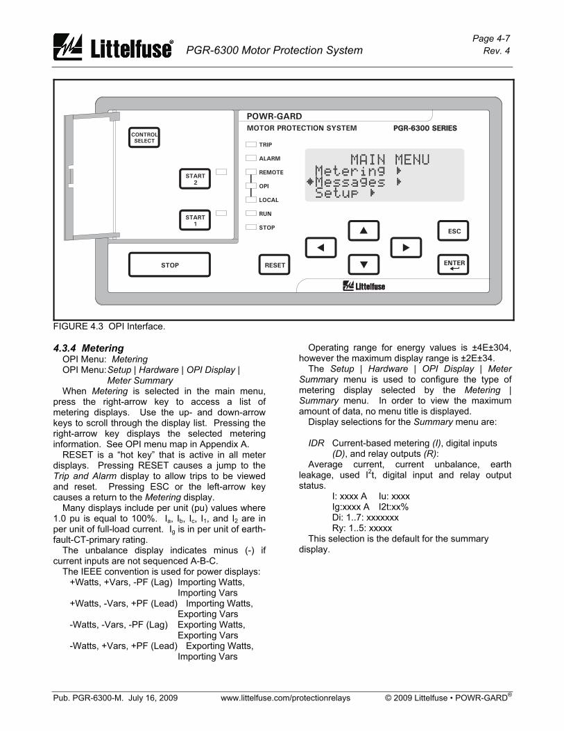
Page 4-7 PGR-6300 Motor Protection System Rev. 4
Pub. PGR-6300-M. July 16, 2009 www.littelfuse.com/protectionrelays © 2009 Littelfuse • POWR-GARD®
PGR-6300 SERIESPGR-6300 SERIESMOTOR PROTECTION SYSTEM
POWR-GARD
RESET
ESC
ENTERSTOP
START
1
START
2
CONTROL
SELECTTRIP
ALARM
REMOTE
OPI
LOCAL
RUN
STOP
²Messages Ñ
MAIN MENUMetering Ñ
Setup Ñ
FIGURE 4.3 OPI Interface. 4.3.4 Metering OPI Menu: Metering OPI Menu: Setup | Hardware | OPI Display |
Meter Summary When Metering is selected in the main menu, press the right-arrow key to access a list of metering displays. Use the up- and down-arrow keys to scroll through the display list. Pressing the right-arrow key displays the selected metering information. See OPI menu map in Appendix A. RESET is a “hot key” that is active in all meter displays. Pressing RESET causes a jump to the Trip and Alarm display to allow trips to be viewed and reset. Pressing ESC or the left-arrow key causes a return to the Metering display. Many displays include per unit (pu) values where 1.0 pu is equal to 100%. Ia, Ib, Ic, I1, and I2 are in per unit of full-load current. Ig is in per unit of earth-fault-CT-primary rating. The unbalance display indicates minus (-) if current inputs are not sequenced A-B-C. The IEEE convention is used for power displays: +Watts, +Vars, -PF (Lag) Importing Watts,
Importing Vars +Watts, -Vars, +PF (Lead) Importing Watts,
Exporting Vars -Watts, -Vars, -PF (Lag) Exporting Watts,
Exporting Vars -Watts, +Vars, +PF (Lead) Exporting Watts,
Importing Vars
Operating range for energy values is ±4E±304, however the maximum display range is ±2E±34. The Setup | Hardware | OPI Display | Meter Summary menu is used to configure the type of metering display selected by the Metering | Summary menu. In order to view the maximum amount of data, no menu title is displayed. Display selections for the Summary menu are: IDR Current-based metering (I), digital inputs
(D), and relay outputs (R): Average current, current unbalance, earth leakage, used I2t, digital input and relay output status.
I: xxxx A Iu: xxxx Ig:xxxx A I2t:xx% Di: 1..7: xxxxxxx Ry: 1..5: xxxxx
This selection is the default for the summary display.
Page 4-8 PGR-6300 Motor Protection System Rev. 4
Pub. PGR-6300-M. July 16, 2009 www.littelfuse.com/protectionrelays © 2009 Littelfuse • POWR-GARD®
IVP Current-based metering (I), voltage (V), unbalance, and power (P):
Average current, current unbalance, earth leakage, used I2t, average voltage, voltage unbalance, power and power factor.
I: xxxx A Iu: x.xx Ig:xxxx A I2t: xx% V: xx.xx kV Vu: x.xx P: xx.x kW PF: x.xx
This selection is applicable for a PGR-6300 using voltage inputs. IVPA Current-based metering (I), voltage (V),
power (P), and analog I/O (A): Average current, average voltage, earth leakage, used I2t, power, power factor, and analog currents.
I: xxxx A V: xx.xx kV Ig:xxxx A I2t:xx% P: xx.x kW PF: x.xx Ai:xxx% Ao: xxx%
This selection is applicable when the PGR-6300 analog output is used in a process control loop. The analog input and output values provide indication of control-system operation. For each metering display, Table 4.4 shows the information that can be displayed. 4.3.5 Messages OPI Menu: Messages Selecting this menu item allows trip and alarm messages, status messages, event records, and statistical data to be viewed and resets to be performed. 4.3.5.1 Trip Reset OPI Menu: Messages | Trip and Alarm Up to fifteen trip and alarm messages can be displayed in a scrollable-list format. Trip messages must be individually selected and reset when the OPI RESET key is used. All trips are simultaneously reset by digital-input reset, with the CTU RESET key or with a communications-network command. Alarms are non-latching and are displayed only for the time that the alarm condition exists. RESET is a "hot key" to the Trip and Alarm display, except during set-point entry. In the Trip and Alarm display, pressing ESC or the left-arrow key causes a return to the display shown when RESET was pressed.
4.3.5.2 Status OPI Menu: Messages | Status Messages This menu is used to display status messages. Status messages are shown in Table 4.5. 4.3.5.3 Data Logging OPI Menu: Messages | Event Records Trip-record data, start-record data, and Emergency Thermal Resets (ETR) are logged. Trip-record data includes the time of trip, cause of trip, and pre-trip(1) data. ETR records contain a snapshot of the data prior to an ETR. Trip or ETR records include: • Time Stamp YY/MM/DD HH:MM:SS, • Vab, Vbc, Vca, Ia, Ib, Ic, and 3I0 at time of trip or ETR, • Unbalance (I2/I1, V2/V1) at time of trip or ETR, • P, Q, S, and PF at time of trip or ETR (1), • Used I2t at time of trip or ETR, • PTC/RTD temperature data if applicable, and • Differential module data if applicable. Start records(2) are triggered by motor current and include: • Time Stamp YY/MM/DD HH:MM:SS, • maximum values of Ia, Ib, Ic, and 3I0 during the
start, • maximum value of I2/I1, V2/V1 during the start, • minimum values of Vab, Vbc, Vca during the start, • maximum differential currents during the start if
applicable, • I2t used during the start(3), • start duration, and • PTC/RTD temperature data if applicable. Record Type ......................... Trip/Start/ETR Number of Records............... 64 (First In First Out) (1) Recorded values for power quantities (P, Q, S,
PF) are averages of measurements over the previous 16 cycles.
(2) Values updated at 0.5-s intervals during a start. Record logged when the run mode is entered.
(3) Starting I2t can be used to determine the I2t Lockout Level. See Section 5.2.
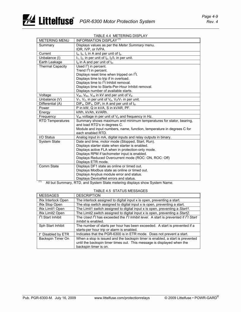
Page 4-9 PGR-6300 Motor Protection System Rev. 4
Pub. PGR-6300-M. July 16, 2009 www.littelfuse.com/protectionrelays © 2009 Littelfuse • POWR-GARD®
TABLE 4.4 METERING DISPLAY METERING MENU INFORMATION DISPLAY (1) Summary Displays values as per the Meter Summary menu.
IDR, IVP, or IVPA. Current Ia, Ib, Ic in A and per unit of Ip. Unbalance (I) I1, I2, in per unit of Ip, I2/I1 in per unit. Earth Leakage Ig in A and per unit of Ie. Thermal Capacity Used I2t in percent.
Trend I2t in percent. Displays reset time when tripped on I2t. Displays time to trip if in overload. Displays time to I2t Inhibit removal. Displays time to Starts-Per-Hour Inhibit removal. Displays number of available starts.
Voltage Vab, Vbc, Vca in kV and per unit of Vp. Unbalance (V) V1, V2, in per unit of Vp, V2/V1 in per unit. Differential (A) DIFa, DIFb, DIFc in A and per unit of Id. Power P in kW, Q in kVA, S in kVAR, PF. Energy kWh, kVAh, kVARh. Frequency Vab voltage in per unit of Vp and frequency in Hz. RTD Temperatures Summary shows maximum and minimum temperatures for stator, bearing,
and load RTD’s in degrees C. Module and input numbers, name, function, temperature in degrees C for each enabled RTD.
I/O Status Analog input in mA, digital inputs and relay outputs in binary. System State Date and time, motor mode (Stopped, Start, Run).
Displays starter state when starter is enabled. Displays active FLA when in protection-only mode. Displays RPM if tachometer input is enabled. Displays Reduced Overcurrent mode (ROC: ON, ROC: Off) Displays ETR mode.
Comm State Displays DF1 state as online or timed out. Displays Modbus state as online or timed out. Displays Anybus module error and status. Displays DeviceNet errors and status.
(1) All but Summary, RTD, and System State metering displays show System Name.
TABLE 4.5 STATUS MESSAGES MESSAGES DESCRIPTION INx Interlock Open The interlock assigned to digital input x is open, preventing a start. INx Stop Open The stop switch assigned to digital input x is open, preventing a start. INx Limit1 Open The Limit1 switch assigned to digital input x is open, preventing a Start1. INx Limit2 Open The Limit2 switch assigned to digital input x is open, preventing a Start2. I2t Start Inhibit The Used I2t has exceeded the I2t Inhibit level. A start is prevented if I2t Start
Inhibit is enabled. Sph Start Inhibit The number of starts per hour has been exceeded. A start is prevented if a
starts-per hour trip or alarm is enabled. t° Disabled by ETR Indicates that the PGR-6300 is in ETR mode. Does not prevent a start. Backspin Timer On When a stop is issued and the backspin timer is enabled, a start is prevented
until the backspin timer times out. This message is displayed when the backspin timer is on.
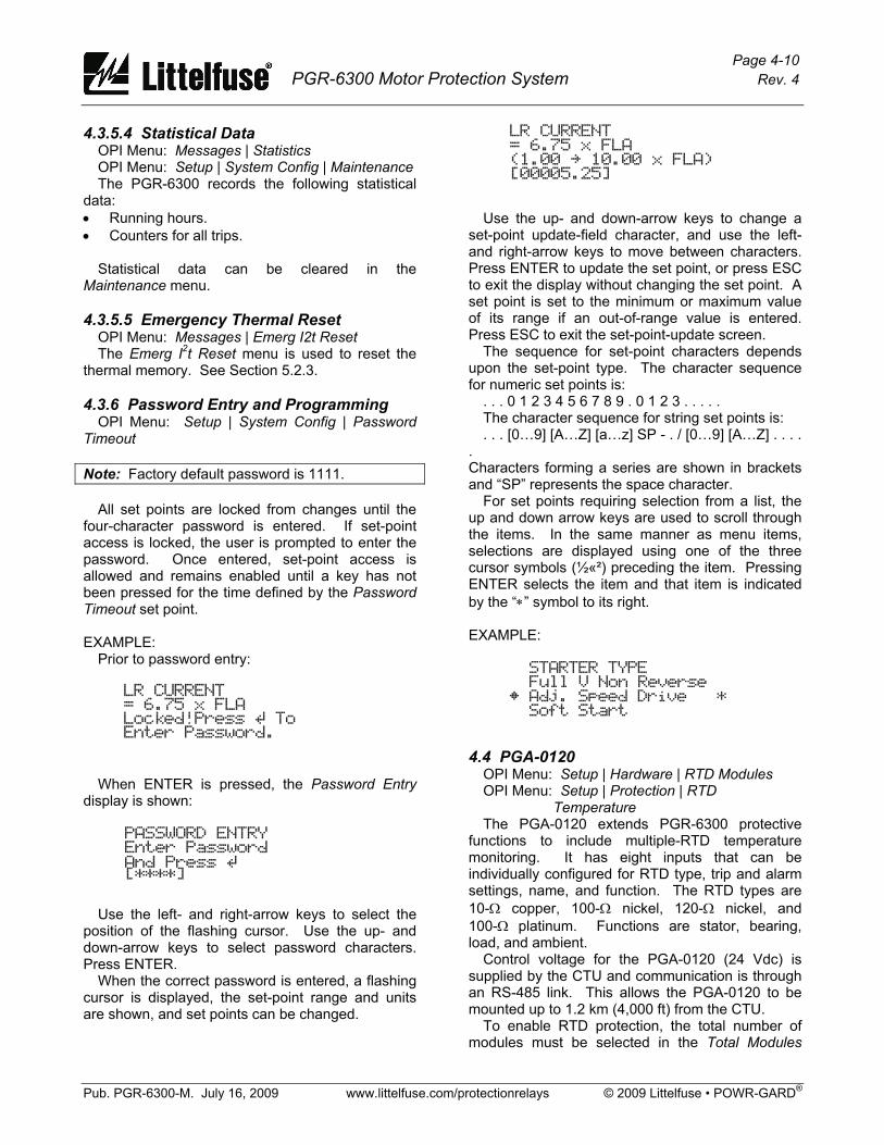
Page 4-10 PGR-6300 Motor Protection System Rev. 4
Pub. PGR-6300-M. July 16, 2009 www.littelfuse.com/protectionrelays © 2009 Littelfuse • POWR-GARD®
4.3.5.4 Statistical Data OPI Menu: Messages | Statistics OPI Menu: Setup | System Config | Maintenance The PGR-6300 records the following statistical data: • Running hours. • Counters for all trips. Statistical data can be cleared in the Maintenance menu. 4.3.5.5 Emergency Thermal Reset OPI Menu: Messages | Emerg I2t Reset The Emerg I2t Reset menu is used to reset the thermal memory. See Section 5.2.3. 4.3.6 Password Entry and Programming OPI Menu: Setup | System Config | Password Timeout Note: Factory default password is 1111. All set points are locked from changes until the four-character password is entered. If set-point access is locked, the user is prompted to enter the password. Once entered, set-point access is allowed and remains enabled until a key has not been pressed for the time defined by the Password Timeout set point. EXAMPLE: Prior to password entry:
When ENTER is pressed, the Password Entry display is shown:
Use the left- and right-arrow keys to select the position of the flashing cursor. Use the up- and down-arrow keys to select password characters. Press ENTER. When the correct password is entered, a flashing cursor is displayed, the set-point range and units are shown, and set points can be changed.
Use the up- and down-arrow keys to change a set-point update-field character, and use the left- and right-arrow keys to move between characters. Press ENTER to update the set point, or press ESC to exit the display without changing the set point. A set point is set to the minimum or maximum value of its range if an out-of-range value is entered. Press ESC to exit the set-point-update screen. The sequence for set-point characters depends upon the set-point type. The character sequence for numeric set points is: . . . 0 1 2 3 4 5 6 7 8 9 . 0 1 2 3 . . . . . The character sequence for string set points is: . . . [0…9] [A…Z] [a…z] SP - . / [0…9] [A…Z] . . . . . Characters forming a series are shown in brackets and “SP” represents the space character. For set points requiring selection from a list, the up and down arrow keys are used to scroll through the items. In the same manner as menu items, selections are displayed using one of the three cursor symbols (½«²) preceding the item. Pressing ENTER selects the item and that item is indicated by the “∗” symbol to its right. EXAMPLE:
4.4 PGA-0120 OPI Menu: Setup | Hardware | RTD Modules OPI Menu: Setup | Protection | RTD
Temperature The PGA-0120 extends PGR-6300 protective functions to include multiple-RTD temperature monitoring. It has eight inputs that can be individually configured for RTD type, trip and alarm settings, name, and function. The RTD types are 10-Ω copper, 100-Ω nickel, 120-Ω nickel, and 100-Ω platinum. Functions are stator, bearing, load, and ambient. Control voltage for the PGA-0120 (24 Vdc) is supplied by the CTU and communication is through an RS-485 link. This allows the PGA-0120 to be mounted up to 1.2 km (4,000 ft) from the CTU. To enable RTD protection, the total number of modules must be selected in the Total Modules

Page 4-11 PGR-6300 Motor Protection System Rev. 4
Pub. PGR-6300-M. July 16, 2009 www.littelfuse.com/protectionrelays © 2009 Littelfuse • POWR-GARD®
menu. Up to three PGA-0120 modules can be used. In the RTD Modules menu, the action to be taken by the CTU in response to loss of communication is selected. When the hardware has been configured, temperature set points and sensor-failure action selections in the RTD Temperature menu are used for RTD temperature protection. See Section 5.25. 4.5 PGA-0140 OPI Menu: Setup | Hardware | DIF Module OPI Menu: Setup | Protection | Differential The PGA-0140 extends PGR-6300 protective functions to include phase-differential monitoring. It has three differential-CT inputs that can be used in a three-CT core-balance connection, a six-differential-CT connection, or a six-CT connection that includes phase-CT PGR-6300 inputs. The core-balance, three-CT connection is recommended. Control voltage for the PGA-0140 (24 Vdc) is supplied by the CTU and communication is through an RS-485 link. This allows the PGA-0140 to be mounted up to 1.2 km (4,000 ft) from the CTU, and the link can be shared by other PGR-6300 I/O modules. Enable the module and loss-of-communications protection in the Hardware | DIF Module menu, and choose protection settings in the Protection | Differential menu. See Section 5.23.

Page 4-12 PGR-6300 Motor Protection System Rev. 4
Pub. PGR-6300-M. July 16, 2009 www.littelfuse.com/protectionrelays © 2009 Littelfuse • POWR-GARD®
This page intentionally left blank.
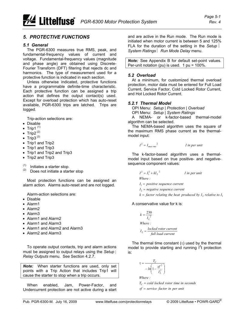
Page 5-1 PGR-6300 Motor Protection System Rev. 4
Pub. PGR-6300-M. July 16, 2009 www.littelfuse.com/protectionrelays © 2009 Littelfuse • POWR-GARD®
5. PROTECTIVE FUNCTIONS 5.1 General The PGR-6300 measures true RMS, peak, and fundamental-frequency values of current and voltage. Fundamental-frequency values (magnitude and phase angle) are obtained using Discrete-Fourier Transform (DFT) filtering that rejects dc and harmonics. The type of measurement used for a protective function is indicated in each section. Unless otherwise indicated, protective functions have a programmable definite-time characteristic. Each protective function can be assigned a trip action that defines the output contact(s) used. Except for overload protection which has auto-reset available, PGR-6300 trips are latched. Trips are logged. Trip-action selections are: • Disable • Trip1 (1) • Trip2 (2) • Trip3 (2) • Trip1 and Trip2 • Trip1 and Trip3 • Trip1 and Trip2 and Trip3 • Trip2 and Trip3 (1) Initiates a starter stop. (2) Does not initiate a starter stop Most protection functions can be assigned an alarm action. Alarms auto-reset and are not logged. Alarm-action selections are: • Disable • Alarm1 • Alarm2 • Alarm3 • Alarm1 and Alarm2 • Alarm1 and Alarm3 • Alarm1 and Alarm2 and Alarm3 • Alarm2 and Alarm3
To operate output contacts, trip and alarm actions must be assigned to output relays using the Setup | Relay Outputs menu. See Section 4.2.7. Note: When starter functions are used, only set points with a Trip Action that includes Trip1 will cause the starter to stop when a trip occurs. When enabled, Jam, Power-Factor, and Undercurrent protection are not active during a start
and are active in the Run mode. The Run mode is initiated when motor current is between 5 and 125% FLA for the duration of the setting in the Setup ⏐ System Ratings ⏐ Run Mode Delay menu. Note: See Appendix B for default set-point values. Per-unit notation (pu) is used. 1 pu = 100%. 5.2 Overload At a minimum, for customized thermal overload protection, motor data must be entered for Full Load Current, Service Factor, Cold Locked Rotor Current, and Hot Locked Rotor Current. 5.2.1 Thermal Model OPI Menu: Setup | Protection | Overload OPI Menu: Setup | System Ratings A NEMA- or k-factor-based thermal-model algorithm can be selected. The NEMA-based algorithm uses the square of the maximum RMS phase current as the thermal-model input:
22rmsmaxII = I in per unit
The k-factor-based algorithm uses a thermal-model input based on true positive- and negative-sequence component values:
12
2
1
22
21
2
ItorelativeIbyproducedheattherelatingfactorkcurrentsequencenegativeI
currentsequencepositiveI:Where
unit per in I kIII
===
+=
A conservative value for k is:
current load fullcurrent rotor lockedI
:WhereI
k
L
L
=
= 2230
The thermal time constant (τ) used by the thermal model to provide starting and running I2t protection is:
unitperinfactorservicesfondssecintimerotorlockedcoldT
:Where
Isfln
T
C
2L
2C
==
⎟⎟⎠
⎞⎜⎜⎝
⎛−−
=τ
1

Page 5-2 PGR-6300 Motor Protection System Rev. 4
Pub. PGR-6300-M. July 16, 2009 www.littelfuse.com/protectionrelays © 2009 Littelfuse • POWR-GARD®
When the motor is stopped, the thermal model uses a time constant that is user selectable as a multiple (Cooling Factor) of the thermal time constant. The cold-curve time-to-trip (t) for current above FLA × sf is:
τ×⎟⎟⎠
⎞⎜⎜⎝
⎛−−= 2
21
Isflnt
The PGR-6300 provides indication of thermal trend and used thermal capacity. Thermal trend is the value that used thermal capacity is tending toward and it is a function of the square of motor current. For currents greater than or equal to FLA × sf, time-to-trip is displayed in Metering | Thermal Capacity. The thermal trend value (Trend I2t) is:
%1002
22 ×⎟
⎟⎠
⎞⎜⎜⎝
⎛=
sfItITrend
For currents less than FLA × sf, the thermal trend value is:
ondssecintimerotorlockedhotTWhere
TTT
sfItITrend
H
C
HC
=
×⎟⎟⎠
⎞⎜⎜⎝
⎛ −×⎟
⎟⎠
⎞⎜⎜⎝
⎛=
:
%1002
22
The curve shown in Fig. 5.1 is a Class-20 thermal-protection curve (20-s trip @ 600% FLA) with a service factor of 1.15. FLA multiplied by service factor is the current at which used thermal capacity begins to tend towards a trip. Time-to-trip approaches infinity when I = FLA × sf. Service factor has little influence on time-to-trip when motor current is greater than 300% FLA. PGR-6300 thermal-overload protection is dynamic. Time to trip at any overload current depends on the value of Used I2t ⎯ as Used I2t increases, time to trip decreases. This is illustrated in Fig. 5.1 by the protection curves labeled 25% Used I2t, 50% Used I2t, and 75% Used I2t. Programming software PGW-COMM has a plot function to display and export PGR-6300 protection curves. An overload alarm occurs when Used I2t reaches the I2t Alarm Level set point. An overload trip occurs when Used I2t reaches 100%. When an overload trip occurs, reset is not allowed until Used I2t falls below the I2t Inhibit Level set point. The time-to-reset in minutes is: t = -τ × Cooling Factor × ln(I2t Inhibit Level)
Time-to-reset is displayed in the Metering ⏐ Thermal Capacity menu. The thermal model has three reset modes; Normal, Auto, and Multiple Motor Seq. The thermal overload reset mode is set using the Setup ⏐ Protection ⏐ Overload ⏐ I2t Reset Type menu. In the Normal mode, a thermal-overload trip reset is not allowed until Used I2t falls below the I2t Inhibit Level setting. A reset input is required to reset the trip. Normal is the default reset mode. In the Auto mode, a thermal-overload trip is automatically reset when Used I2t falls below the I2t Inhibit Level setting. Caution: If the starter circuit is configured for two-wire control, the motor can start without warning when Auto mode is selected. A warning label may be required. In the Multiple Motor Seq. mode, Used I2t decreases exponentially with a fixed two-second time constant when there is no motor current. This mode is used in applications where one overload relay is used to protect several motors operating in sequence with only one motor running at any one time. A two-second stop is required between starts so that Used I2t decreases sufficiently to allow the next motor to start. It is assumed that each motor is allowed to cool between starts. Motor life may be decreased if this feature is used in single-motor applications. When a thermal trip occurs, the trip is latched but can be reset two seconds after the trip. When I2t Start Inhibit is enabled, the I2t Inhibit Level set point can be used to prevent a start with insufficient I2t available. When Used I2t is above the I2t Inhibit Level set point and motor current is not detected, Alarm1 is issued, starter functions Start1 and Start2 are disabled, and the relay assigned to Start Inhibit is energized. The time until a start is permitted is displayed in Metering | Thermal Capacity, and I2t Inhibit Alarm is displayed in the Trip and Alarm message window. When Used I2t falls below the I2t Inhibit Level set point, the relay assigned to Start Inhibit is de-energized, the inhibit alarm is cancelled, and starter functions Start1 and Start2 are enabled. Trips require a manual reset. I2t Start Inhibit is removed when current is detected. This applies in both Starter and Protection-only modes. The Start-Inhibit relay is shared with the Starts-Per-Hour function. See Section 5.21. If the motor is equipped with RTD sensors, the thermal model can compensate for high ambient temperature and loss of ventilation. See Section 5.26.
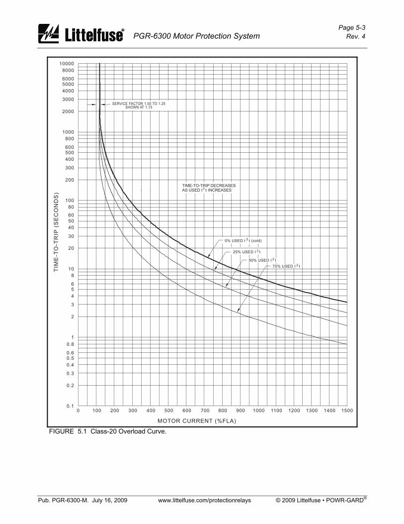
Page 5-3 PGR-6300 Motor Protection System Rev. 4
Pub. PGR-6300-M. July 16, 2009 www.littelfuse.com/protectionrelays © 2009 Littelfuse • POWR-GARD®
MOTOR CURRENT (%FLA)
0 100 200 300 400 500 600 700 800 900 1000
TIM
E-T
O-T
RIP
(SE
CO
ND
S)
1
2
3
4
56
8
10
20
30
40
50
60
80
100
200
300
400
500600
800
1000
2000
3000
4000
50006000
8000
10000
SERVICE FACTOR 1.00 TO 1.25SHOWN AT 1.15
0% USED I t (cold)2
25% USED I t2
2TIME-TO-TRIP DECREASESAS USED I t INCREASES
1100 1200 1300 1400 15000.1
0.2
0.3
0.4
0.50.6
0.8
50% USED I t2
75% USED I t2
FIGURE 5.1 Class-20 Overload Curve.
Page 5-4 PGR-6300 Motor Protection System Rev. 4
Pub. PGR-6300-M. July 16, 2009 www.littelfuse.com/protectionrelays © 2009 Littelfuse • POWR-GARD®
I2t used during each start is recorded in Messages ⏐ Event Records. This information can be used to determine the I2t Inhibit Level set point to ensure sufficient I2t is available to complete a start, and to minimize thermal-overload-reset time. FLA Rating........................1.00 to 5,000.00 A Service Factor ..................1.00 to 1.25 Locked-Rotor Current.......1.50 to 10.00 x FLA Hot Locked-Rotor Time ....0.10 to 100.00 s Cold Locked-Rotor Time ..0.10 to 100.00 s Cooling Factor ..................0.10 to 10.00 Model Type:......................NEMA, K-Factor I2t Reset Type...................Normal, Auto, Multiple Motor Sequence K-Factor............................1.00 to 10.00 I2t Alarm............................0.50 to 1.00 pu I2t Inhibit Level ..................0.10 to 0.90 pu I2t Start Inhibit ...................Enable/Disable Protection .........................Enable/Disable Trip1, 2, 3
Enable/Disable Alarm1, 2, 3 Measurement Method ......DFT or RMS 5.2.2 Locked-Rotor Times In all cases, values for TH and TC should be obtained from the motor manufacturer. The following information is provided to assist in selecting values for TH and TC only if manufacturer data is not available. Heater-style overload elements are available as Class 10, Class 20, or Class 30. Class 20 is recommended for general applications, Class 10 is used for motors with short locked-rotor time capability, and Class 30 is used in high-inertia applications to allow additional accelerating time where motors are within Class-30 performance requirements. These overloads can be replicated by setting TC = 10, 20, or 30 s; TH = 0.1 s; and Locked-Rotor Current = 6.00 x FLA. An induction motor built to the NEMA MG 1 standard is capable of • two starts in succession (coasting to rest between
starts) with the motor initially at ambient temperature (cold start), and
• one start with the motor initially at a temperature not exceeding its rated-load operating temperature (hot start).
Since the connected load has a direct influence on motor heating during a start, NEMA MG 1 defines the load torque and the load inertia (Wk2) for these starts as a function of the motor’s rated power and synchronous speed. To satisfy the cold-start requirement, a start must not use more than 50% thermal capacity. To satisfy the hot-start requirement, used thermal capacity at steady state must be less than 50%.
If the thermal model in the PGR-6300 has the correct value of TC and if Used I2t increases by 50% during a start, the load is equal to the NEMA-defined load and two starts from cold will be permitted. If Used I2t increases by more than 50% during a start, the load is greater than the NEMA-defined load and two starts from cold should not be permitted — a delay is required between starts. The appropriate delay can be obtained by enabling I2t Start Inhibit and setting the I2t Inhibit Level equal to 100% minus the I2t used during a start (a slightly lower level is recommended to allow for supply and load variations). If Used I2t increases by less than 50% during a start, the load is less than the NEMA-defined load and two starts from cold will be permitted. The magnitude of TH relative to TC determines if a hot start will be permitted if I2t Start Inhibit is enabled and the I2t Inhibit Level is set as described above. If Used I2t increases by 50% or less during a start, a hot start will be permitted if TH is equal to or greater than 50% of TC. Increasing TH above 50% of TC is not recommended unless specific information is available with respect to TH. 5.2.3 Emergency Thermal Reset OPI Menu: Messages | Emerg I2t Reset | Reset I2t Memory Emergency Thermal Reset (ETR) sets Used I2t to 0%, resets starts-per-hour variables, and disables PTC and RTD temperature trips. Program access is required. Disabled-temperature protection is indicated by t° Disabled by ETR in the Status Mesages display. If PTC or RTD temperature protection is not enabled, t° Disabled by ETR will not be displayed. Stator RTD or PTC trips are reset when ETR is performed regardless of measured temperatures. Temperature protection must be re-enabled in the Messages | Emerg I2t Reset | Reenable Temp menu, or by cycling supply voltage. Temperature alarms and sensor verification remain enabled during ETR. Caution: Temperature protection is not automatically re-enabled after an Emergency Thermal Reset. 5.3 Overcurrent OPI Menu: Setup | Protection | Overcurrent Overcurrent protection is based on the largest fundamental-frequency component (DFT) of the three phase currents. An alarm-level setting is not provided. When enabled, overcurrent protection is active at all times. It is not bypassed during a start.
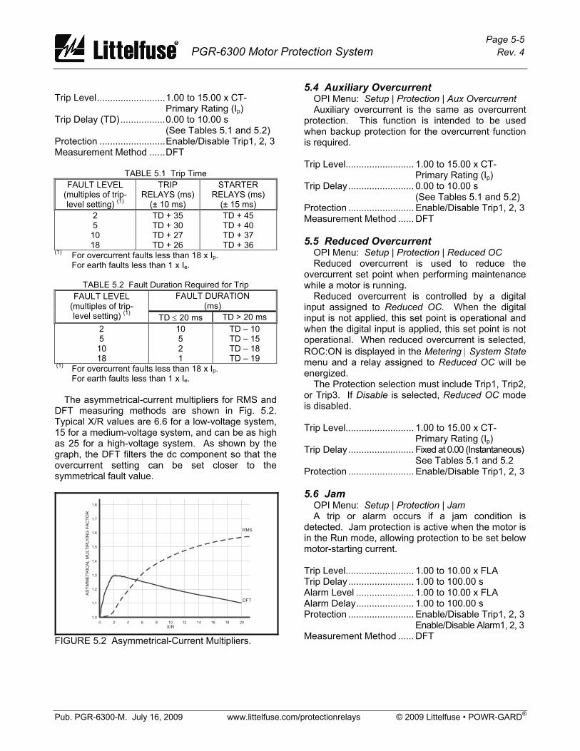
Page 5-5 PGR-6300 Motor Protection System Rev. 4
Pub. PGR-6300-M. July 16, 2009 www.littelfuse.com/protectionrelays © 2009 Littelfuse • POWR-GARD®
Trip Level..........................1.00 to 15.00 x CT-
Primary Rating (Ip) Trip Delay (TD).................0.00 to 10.00 s (See Tables 5.1 and 5.2) Protection .........................Enable/Disable Trip1, 2, 3 Measurement Method ......DFT
TABLE 5.1 Trip Time
FAULT LEVEL (multiples of trip-level setting) (1)
TRIP RELAYS (ms)
(± 10 ms)
STARTER RELAYS (ms)
(± 15 ms) 2 5
10 18
TD + 35 TD + 30 TD + 27 TD + 26
TD + 45 TD + 40 TD + 37 TD + 36
(1) For overcurrent faults less than 18 x Ip. For earth faults less than 1 x Ie.
TABLE 5.2 Fault Duration Required for Trip
FAULT DURATION (ms)
FAULT LEVEL (multiples of trip- level setting) (1) TD ≤ 20 ms TD > 20 ms
2 5 10 18
10 5 2 1
TD – 10 TD – 15 TD – 18 TD – 19
(1) For overcurrent faults less than 18 x Ip. For earth faults less than 1 x Ie. The asymmetrical-current multipliers for RMS and DFT measuring methods are shown in Fig. 5.2. Typical X/R values are 6.6 for a low-voltage system, 15 for a medium-voltage system, and can be as high as 25 for a high-voltage system. As shown by the graph, the DFT filters the dc component so that the overcurrent setting can be set closer to the symmetrical fault value.
FIGURE 5.2 Asymmetrical-Current Multipliers.
5.4 Auxiliary Overcurrent OPI Menu: Setup | Protection | Aux Overcurrent Auxiliary overcurrent is the same as overcurrent protection. This function is intended to be used when backup protection for the overcurrent function is required. Trip Level.......................... 1.00 to 15.00 x CT-
Primary Rating (Ip) Trip Delay......................... 0.00 to 10.00 s (See Tables 5.1 and 5.2) Protection ......................... Enable/Disable Trip1, 2, 3 Measurement Method ...... DFT 5.5 Reduced Overcurrent OPI Menu: Setup | Protection | Reduced OC Reduced overcurrent is used to reduce the overcurrent set point when performing maintenance while a motor is running. Reduced overcurrent is controlled by a digital input assigned to Reduced OC. When the digital input is not applied, this set point is operational and when the digital input is applied, this set point is not operational. When reduced overcurrent is selected, ROC:ON is displayed in the Metering | System State menu and a relay assigned to Reduced OC will be energized. The Protection selection must include Trip1, Trip2, or Trip3. If Disable is selected, Reduced OC mode is disabled. Trip Level.......................... 1.00 to 15.00 x CT-
Primary Rating (Ip) Trip Delay......................... Fixed at 0.00 (Instantaneous) See Tables 5.1 and 5.2 Protection ......................... Enable/Disable Trip1, 2, 3 5.6 Jam OPI Menu: Setup | Protection | Jam A trip or alarm occurs if a jam condition is detected. Jam protection is active when the motor is in the Run mode, allowing protection to be set below motor-starting current. Trip Level.......................... 1.00 to 10.00 x FLA Trip Delay......................... 1.00 to 100.00 s Alarm Level ...................... 1.00 to 10.00 x FLA Alarm Delay...................... 1.00 to 100.00 s Protection ......................... Enable/Disable Trip1, 2, 3
Enable/Disable Alarm1, 2, 3 Measurement Method ...... DFT
Page 5-6 PGR-6300 Motor Protection System Rev. 4
Pub. PGR-6300-M. July 16, 2009 www.littelfuse.com/protectionrelays © 2009 Littelfuse • POWR-GARD®
5.7 Earth Fault OPI Menu: Setup | Protection | Earth Fault Earth-fault protection is based on the fundamental-frequency component of zero-sequence current. Trip Level..........................0.05 to 1.00 x EF-CT-
Primary Rating (Ie) Trip Delay .........................0.00 to 100.00 s (See Tables 5.1 and 5.2) Alarm Level.......................0.05 to 1.00 x Ie Alarm Delay......................0.00 to 100.00 s Protection ........................Enable/Disable Trip1, 2, 3 Enable/Disable Alarm1, 2, 3 Measurement Method ......DFT 5.8 Current Unbalance OPI Menu: Setup | Protection | Unbalance (I) Positive-sequence current (I1) and negative-sequence current (I2) are used to determine current unbalance (I2/I1). The unbalance display range is 0.00 to 1.00 where 1.00 is 100% unbalance—a single-phase condition. Negative unbalance will be indicated if current inputs are connected B-A-C. Severe unbalance may be indicated if phase-CT polarity is incorrect. Trip Level..........................0.05 to 1.00 Trip Delay .........................1.00 to 100.00 s Alarm Level.......................0.05 to 1.00 Alarm Delay......................1.00 to 100.00 s Protection .........................Enable/Disable Trip1, 2, 3
Enable/Disable Alarm1, 2, 3 Measurement Method ......DFT 5.9 Phase Loss—Current OPI Menu: Setup | Protection | Phase Loss (I) Phase loss is a severe form of unbalance. When phase loss occurs, negative-sequence current (I2) is equal to positive-sequence current (I1) and current unbalance is 100% or 1.00 pu. The phase-loss algorithm considers I2/I1 from 0.90 to 1.00 to be a phase loss. Set the phase-loss trip delay lower than the unbalance trip delay to avoid an unbalance trip in the event of a phase loss. Trip Delay .........................1.00 to 100.00 s Protection .........................Enable/Disable Trip1, 2, 3 Measurement Method ......DFT 5.10 Phase Reverse—Current OPI Menu: Setup | Protection | Phase Rev (I) If the current phase sequence is B-A-C, the magnitude of negative-sequence current will be larger than the magnitude of positive-sequence current.
Trip and Alarm Delay (1).... 1.00 to 100.00 s Protection ......................... Enable/Disable Trip1, 2, 3 Enable/Disable Alarm1, 2, 3 Measurement Method ...... DFT (1) Single set point applies to Trip and Alarm. 5.11 Undercurrent OPI Menu: Setup | Protection | Undercurrent Undercurrent protection is loss-of-load protection and is active when the motor is in the Run mode. A trip or alarm is initiated if current remains below the set point for the programmed delay. Trip Level.......................... 0.10 to 1.00 x FLA Trip Delay......................... 1.00 to 100.00 s Alarm Level ...................... 0.10 to 1.00 x FLA Alarm Delay...................... 1.00 to 100.00 s Protection ......................... Enable/Disable Trip1, 2, 3
Enable/Disable Alarm1, 2, 3 Measurement Method ...... DFT 5.12 Overvoltage OPI Menu: Setup | Protection | Overvoltage A trip or alarm occurs if the maximum line-to-line voltage exceeds the set point. Trip Level.......................... 1.00 to 1.40 x System
Voltage Rating (Vp) Trip Delay......................... 1.00 to 500.00 s Alarm Level ...................... 1.00 to 1.40 x Vp Alarm Delay...................... 1.00 to 500.00 s Protection ......................... Enable/Disable Trip1, 2, 3
Enable/Disable Alarm1, 2, 3 Measurement Method ...... DFT 5.13 Voltage Unbalance OPI Menu: Setup | Protection | Unbalance (V) Positive-sequence voltage (V1) and negative-sequence voltage (V2) are used to determine voltage unbalance (V2/V1). The unbalance display range is 0.00 to 1.00 where 1.00 is 100% unbalance—a single-phase condition. A negative unbalance will be indicated if voltage inputs are connected B-A-C.
Trip Level.......................... 0.05 to 1.00 Trip Delay......................... 1.00 to 100.00 s Alarm Level ...................... 0.05 to 1.00 Alarm Delay...................... 1.00 to 100.00 s Protection ......................... Enable/Disable Trip1, 2, 3
Enable/Disable Alarm1, 2, 3 Measurement Method ...... DFT

Page 5-7 PGR-6300 Motor Protection System Rev. 4
Pub. PGR-6300-M. July 16, 2009 www.littelfuse.com/protectionrelays © 2009 Littelfuse • POWR-GARD®
5.14 Phase Loss—Voltage OPI Menu: Setup | Protection | Phase Loss (V) Phase loss is a severe form of unbalance. When phase loss occurs, negative-sequence voltage (V2) is equal to positive-sequence voltage (V1) and voltage unbalance is 100% or 1.00 pu. The phase-loss algorithm considers V2/V1 from 0.90 to 1.00 to be a phase loss. Set the phase-loss trip delay lower than the unbalance trip delay to avoid an unbalance trip in the event of a phase loss. Trip Delay .........................1.00 to 100.00 s Protection .........................Enable/Disable Trip1, 2, 3 Measurement Method ......DFT 5.15 Phase Reverse—Voltage OPI Menu: Setup | Protection | Phase Rev (V) If the voltage phase sequence is B-A-C, the magnitude of the negative-sequence voltage will be larger than the magnitude of the positive-sequence voltage. Trip and Alarm Delay (1)....1.00 to 100.00 s Protection .........................Enable/Disable Trip1, 2, 3 Enable/Disable Alarm1, 2, 3 Measurement Method ......DFT (1) Single set point applies to Trip and Alarm. 5.16 Undervoltage OPI Menu: Setup | Protection | Undervoltage A trip or alarm occurs if the minimum line-to-line voltage is less than the set point. Trip Level..........................0.50 to 1.00 x System
Voltage Rating (Vp) Trip Delay .........................1.00 to 500.00 s Alarm Level.......................0.50 to 1.00 x Vp Alarm Delay......................1.00 to 500.00 s Protection .........................Enable/Disable Trip1, 2, 3
Enable/Disable Alarm1, 2, 3 Measurement Method ......DFT 5.17 Power Factor—Quadrant 4 OPI Menu: Setup | Protection | PF Quandrant4 A trip or alarm occurs if the absolute value of power factor in quadrant 4 is less than the set point. In quadrant 4, both Watts and Vars are positive (Importing). Power-factor protection is active when the motor is in the Run mode.
Trip Level.......................... 0.50 to 1.00 Trip Delay......................... 0.20 to 500.00 s Alarm Level ...................... 0.50 to 1.00 Alarm Delay...................... 0.20 to 500.00 s Protection ......................... Enable/Disable Trip1, 2, 3
Enable/Disable Alarm1, 2, 3 5.18 Power Factor—Quadrant 3 OPI Menu: Setup | Protection | PF Quandrant3 A trip or alarm occurs if the absolute value of power factor in quadrant 3 is less than the set point. In quadrant 3, Watts are negative (Exporting) and Vars are positive (Importing). Power-factor protection is active when the motor is in the Run mode. Trip Level.......................... 0.50 to 1.00 Trip Delay......................... 0.20 to 500.00 s Alarm Level ...................... 0.50 to 1.00 Alarm Delay...................... 0.20 to 500.00 s Protection ......................... Enable/Disable Trip1, 2, 3
Enable/Disable Alarm1, 2, 3 5.19 Underfrequency OPI Menu: Setup | Protection | Underfrequency A trip or alarm occurs when the frequency of the input voltage (VA) is below the set point. Underfrequency protection is inhibited when the input voltage is less than 50% of rated input (Vp). Trip Level.......................... 30.00 to 80.00 Hz Trip Delay......................... 0.50 to 500.00 s Alarm Level ...................... 30.00 to 80.00 Hz Alarm Delay...................... 0.5 to 500.00 s Protection ......................... Enable/Disable Trip1, 2, 3 Enable/Disable Alarm1, 2, 3 5.20 Overfrequency OPI Menu: Setup | Protection | Overfrequency A trip or alarm occurs when the frequency of the input voltage (VA) is above the set point. Overfrequency protection is inhibited when the input voltage is less than 50% of rated input (Vp). Trip Level.......................... 30.00 to 80.00 Hz Trip Delay......................... 0.50 to 500.00 s Alarm Level ...................... 30.00 to 80.00 Hz Alarm Delay...................... 0.50 to 500.00 s Protection ......................... Enable/Disable Trip1, 2, 3
Enable/Disable Alarm1, 2, 3
Page 5-8 PGR-6300 Motor Protection System Rev. 4
Pub. PGR-6300-M. July 16, 2009 www.littelfuse.com/protectionrelays © 2009 Littelfuse • POWR-GARD®
5.21 Starts Per Hour / Time Between Starts OPI Menu: Setup | Protection | Starts Per Hour Starts-Per-Hour and Time-Between-Starts are useful limits in a protective relay that incorrectly responds to current below FLA. If the relay’s thermal model accurately tracks a motor’s used thermal capacity under all conditions, Starts-Per-Hour and Time-Between-Starts are features that provide no additional protection. The PGR-6300 does not require these features to provide protection, but they are included to satisfy protection strategies designed for protective relays without dynamic thermal modeling. The Starts-Per-Hour feature ensures that the programmed number of starts per hour is not exceeded and the Time-Between-Starts feature ensures that the programmed time has elapsed between starts. The available number of starts and time between starts is also a function of the thermal model’s Used I2t value. Consequently, the number of starts may be less than the starts-per-hour value and the time between starts may be longer than the set-point value. The number of starts and time between starts is checked when the motor is stopped. A Starts/Hour Trip or Starts/Hour Alarm is issued if a start will exceed the # Starts Per Hour setting or if the time since the previous start is less than the Time Between setting. When a Starts/Hour Trip or Starts/Hour Alarm is issued, the output relay assigned to Start Inhibit is energized. The Start Inhibit relay is non-latching and can be used as a start permissive. A Starts/Hour Trip will remain latched until a reset is issued. The Start Inhibit relay is shared with the thermal model’s I2t Inhibit feature. If motor current is detected regardless of the alarm or trip condition, the Starts/Hour Alarm is removed, and Starts/Hour Trip can be reset. The starts-per-hour algorithm remains active but any trips or alarms are suppressed until the motor is stopped. The status of Starts-Per-Hour and Time-Between-Starts is displayed in the Metering | Thermal Capacity menu. If there are no trips or alarms, the number of available starts (Sph Available) is displayed and if a trip or alarm is present, the inhibit time (Sph Inhibit) is displayed. Since the Metering | Thermal Capacity menu is also used to display the thermal model status, messages are prioritized as follows: • I2t Reset Time(1) • I2t Trip Time(1) • I2t Inhibit Time(1) • Starts Per Hour Inhibit Time(3) • Starts Available(2) (3)
An Emergency Thermal Reset (ETR) can be used to initialize all thermal and starts-per-hour variables and to reset a starts-per-hour trip. See Section 5.2.3. Time Between Starts.....0.00 to 500.00 Minutes Starts Per Hour(2)...........1 to 10 Protection ......................Enable/Disable Trip 1, 2, 3 Enable/Disable Alarm 1, 2, 3 (1) Calculated from thermal model data. (2) The display range for the number of available
starts is –9 to +10. (3) Initialized when supply voltage is cycled. 5.22 Failure to Accelerate and Underspeed OPI Menu: Setup | Protection | Accel Failure OPI Menu: Setup | 4-20 Analog In | Input Function OPI Menu: Setup | Digital Inputs | Tachometer Failure-to-accelerate and underspeed protection are available if the PGR-6300 has a tachometer signal. The tachometer signal can originate from the High Speed Input (HSI) or an analog input. If the analog input is set to Motor Speed, it is used as the input to the algorithm, otherwise the digital tachometer (HSI) is used. The failure-to-accelerate algorithm is activated whenever a start is detected. Start detection is based on motor current. Set points 1 to 3 are sequentially checked to confirm acceleration. While running, the tachometer signal is continuously measured and a trip occurs if the speed falls below the Speed 3 setting. Time 1 must be set less than or equal to Time 2 and Time 2 must be set less than or equal to Time 3. To enable display of the speed in the Metering | System State menu, select Enable in the Setup ⏐ Digital Input ⏐ Tachometer ⏐ Enable/Disable menu, when the HSI input is used. Speed 1............................ 1.00 to 100% Sync Speed Time 1 .............................. 1.00 to 1000.00 s Speed 2............................ 1.00 to 100% Sync Speed Time 2 .............................. 1.00 to 1000.00 s Speed 3............................ 1.00 to 100% Sync Speed Time 3 .............................. 1.00 to 1000.00 s Protection ......................... Enable/Disable Trip1, 2, 3 5.23 Differential Current Protection OPI Menu: Setup | Protection | Differential OPI Menu: Setup | Hardware | DIF Module OPI Menu: Setup | System Ratings | DF-CT Primary The PGA-0140 (DIF Module) provides three-phase differential protection. It is intended to be used specifically for motor protection and not intended for feeder or transformer differential protection.

Page 5-9 PGR-6300 Motor Protection System Rev. 4
Pub. PGR-6300-M. July 16, 2009 www.littelfuse.com/protectionrelays © 2009 Littelfuse • POWR-GARD®
Enable the module and communications loss using the Setup ⏐ Hardware ⏐ DIF Module menu. The module uses I/O module communications and both trip and alarm actions are available in the event of communications loss. Set DF-CT Primary equal to the differential-CT-primary rating. For the PGR-6300 summation connection PH-CT Primary must be equal to DF-CT Primary. Trip and alarm settings are based on multiples of the DF-CT Primary rating (Id). Trip Level..........................0.10 to 15.00 x Id Trip Delay .........................0.00 to 10.00 s Alarm Level.......................0.10 to 15.00 x Id Alarm Delay......................0.00 to 10.00 s Protection .........................Enable/Disable Trip1,2,3 Enable/Disable Alarm1,2,3 Measurement Method ......DFT c/w CT saturation compensation. 5.24 PTC Temperature OPI Menu: Setup | Protection | PTC Temperature A positive-temperature-coefficient (PTC) thermistor input is provided on the CTU. The total resistance of series-connected PTC thermistors must be less than 1,500 Ω at 20°C. A trip or alarm will occur when series resistance exceeds 2,900 Ω. During Emergency Thermal Reset, a PTC trip is reset and PTC-temperature protection is disabled. See Section 5.2.3. Protection .........................Enable/Disable Trip1, 2, 3 Enable/Disable Alarm1, 2, 3 5.25 RTD Temperature OPI Menu: Setup | Protection | RTD Temperature Up to three PGA-0120 (RTD Modules) can be connected to the CTU. Select the number of modules in the Setup | Hardware | RTD Modules menu. Each PGA-0120 can monitor eight RTD’s for a total of twenty-four RTD’s. RTD type, function, and trip and alarm set points are programmable for each RTD. When an RTD type is selected, both Trip1 and Alarm1 functions are enabled. During Emergency Thermal Reset, an RTD trip is reset and RTD-temperature protection is disabled. See Section 5.2.3. RTD failure detection is provided. The actions for an RTD failure are selectable as Trip1, 2, or 3 and as Alarm1, 2, or 3. The selections apply to all RTD's.
Name................................ 18 Character, Alphanumeric Type ................................. Disable, Pt100, Ni100,
Ni120, Cu10 Function............................ Stator, Bearing, Load,
Ambient Trip and Alarm Range ...... 40.00 to 200.00°C Display Range.................. -40.00 to 200.00°C 5.26 Hot-Motor Compensation OPI Menu: Setup | Protection | RTD Temperature If hot-motor compensation (HMC) is enabled, the maximum stator-RTD temperature is used to bias the thermal model by increasing Used I2t when the RTD temperature is greater than the thermal-model temperature. Two set points are used to define the compensation. See Fig. 5.3. HMC Low is the stator temperature where compensation begins at 0% I2t. HMC High is the stator temperature where compensation ends at 100% I2t.
100%
0%
BIA
SI²
t
HMC HIGHHMC LOW
RTD TEMPERATURE
FIGURE 5.3 Used I2t Bias Curve. HMC Low.......................... 40.00 to 200.00°C HMC High......................... 40.00 to 200.00°C Protection ......................... Enable/Disable Note: Hot-motor compensation will not be active unless the HMC High set point is at least 10°C above the HMC Low set point. 5.27 Analog Input OPI Menu: Setup | Analog Input | 4–20 Input Type The analog input function is selectable as Metering Only, Protection, Sync to ASD, or Motor Speed.

Page 5-10 PGR-6300 Motor Protection System Rev. 4
Pub. PGR-6300-M. July 16, 2009 www.littelfuse.com/protectionrelays © 2009 Littelfuse • POWR-GARD®
5.27.1 Protection OPI Menu: Setup | 4-20 Analog In | Protection The protection input has high-level and low-level trip and alarm set points. A high-level trip or alarm occurs when the 4–20-mA input exceeds the high-level trip or alarm set point, and a low-level trip or alarm occurs when the 4–20-mA input is lower than the low-level trip or alarm set point. Trip action is fixed at Trip1 and alarm action is fixed at Alarm1. High Level Trip .................0.10 to 20.00 mA Low Level Trip ..................0.10 to 20.00 mA Trip Delay .........................0.01 to 100.00 s High Level Alarm ..............0.10 to 20.00 mA Low Level Alarm...............0.10 to 20.00 mA Alarm Delay......................0.01 to 100.00 s 5.27.2 Synchronize to ASD OPI Menu: Setup | 4-20 Analog In | Sync to ASD When Sync to ASD is selected, the PGR-6300 uses the 4–20-mA input to set the internal sampling rate for current and voltage inputs so that protection and metering functions use accurate RMS and DFT values from 10.00 to 70.00 Hz. 4-mA Frequency (lower)...0.00 to 70.00 Hz 20-mA Frequency (upper) 0.00 to 70.00 Hz Frequency Range.............10.00 to 70.00 Hz 5.27.3 Motor Speed OPI Menu: Setup | 4-20 Analog In | Motor Speed When the analog input type is selected as Motor Speed, the 4–20-mA analog input is used as the speed input. This selection overrides the selections for the high-speed tachometer input and failure-to-accelerate protection uses the analog input as the source of speed information. 4-mA Speed......................0.00 to 100% Sync Speed 20-mA Speed ...................0.00 to 100% Sync Speed
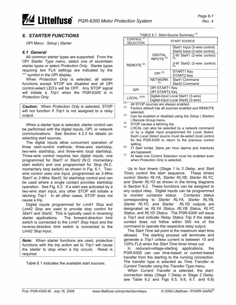
Page 6-1 PGR-6300 Motor Protection System Rev. 4
Pub. PGR-6300-M. July 16, 2009 www.littelfuse.com/protectionrelays © 2009 Littelfuse • POWR-GARD®
6. STARTER FUNCTIONS OPI Menu: Setup | Starter 6.1 General All common starter types are supported. From the OPI Starter Type menu, select one of seventeen starter types or select Protection Only. Starter types requiring two FLA settings are indicated by the “x” symbol in the OPI display. When Protection Only is selected, all starter functions except STOP are disabled and all OPI control-select LED’s will be OFF. Any STOP signal will initiate a Trip1 when the PGR-6300 is in Protection Only. Caution: When Protection Only is selected, STOP will not function if Trip1 is not assigned to a relay output. When a starter type is selected, starter control can be performed with the digital inputs, OPI, or network communications. See Section 4.3.3 for details on selecting start sources. The digital inputs allow concurrent operation of three start-control methods; three-wire start/stop, two-wire start/stop, and three-wire local start/stop. Three-wire control requires two digital inputs, one programmed for Start1 or Start2 (N.O. momentary start switch) and one programmed for Stop (N.C. momentary stop switch) as shown in Fig. 6.1. Two-wire control uses one input, programmed as 2-Wire Start1 or 2-Wire Start2, for start/stop control and can be used where a single contact provides start/stop operation. See Fig. 6.2. If a start was activated by a two-wire start input, any other STOP will initiate a latching Trip1. In all other cases, STOP does not cause a trip. Digital inputs programmed for Limit1 Stop and Limit2 Stop are used to provide stop control for Start1 and Start2. This is typically used in reversing starter applications. The forward-direction limit switch is connected to the Limit1 Stop input and the reverse-direction limit switch is connected to the Limit2 Stop input. Note: When starter functions are used, protective functions with the trip action set to Trip1 will cause the starter to stop when a trip occurs. Reset is required. Table 6.1 indicates the available start sources.
TABLE 6.1 Start-Source Summary (1) CONTROL (7)
SELECTION START SOURCE
Start1 Input (3-wire control) Start2 Input (3-wire control)
DIGITAL INPUTS (3)
2-W Start1 (2-wire control) (4) 2-W Start2 (2-wire control) (4)
OPI (3) START1 Key START2 Key
REMOTE (2)
NETWORK (3)
Start1 Command Start2 Command
OPI OPI START1 Key OPI START2 Key
LOCAL (5)(6) Digital-Input Local Start1 (3-wire) Digital-Input Local Start2 (3-wire)
(1) All STOP sources are always enabled. (2) Factory default has all sources enabled and REMOTE
selected. (3) Can be enabled or disabled using the Setup | Starters
| Remote Group menu. (4) STOP causes a latching trip. (5) LOCAL can also be selected by a network command
or by a digital input programmed for Local Select. Each Local Select source must de-select local control for the PGR-6300 to return to the previous control setting.
(6) I2t Start Inhibit, Starts per Hour alarms and Interlocks are bypassed.
(7) At least one Control Selection must be enabled even when Protection Only is selected.
Up to four timers (Stage 1 to 3 Delay, and Start Time) control the start sequence. These timers control Starter RLYA, Starter RLYB, Starter RLYC, and Starter RLYD as shown in the timing diagrams in Section 6.2. These functions can be assigned to any output relay. Digital inputs can be programmed to monitor contactor status. Contactor status corresponding to Starter RLYA, Starter RLYB, Starter RLYC, and Starter RLYD outputs are designated as RLYA Status, RLYB Status, RLYC Status, and RLYD Status. The PGR-6300 will issue a Trip1 and indicate Relay Status Trip if the status contact does not follow within 500 ms of the command to operate the respective relay output. The Start Time set point is the maximum start time allowed. The starting process will terminate and generate a Trip1 unless current is between 10 and 125% FLA when the Start Time timer times out. In reduced-voltage-starting applications, the PGR-6300 can use time-based or current-based transfer from the starting to the running connection. The transfer type is selected as Time Transfer or Current Transfer using the Transfer Type menu. When Current Transfer is selected, the start-connection delay (Stage 1 Delay or Stage 2 Delay, see Table 6.2 and Figs 6.5, 6.6, 6.7, and 6.8)
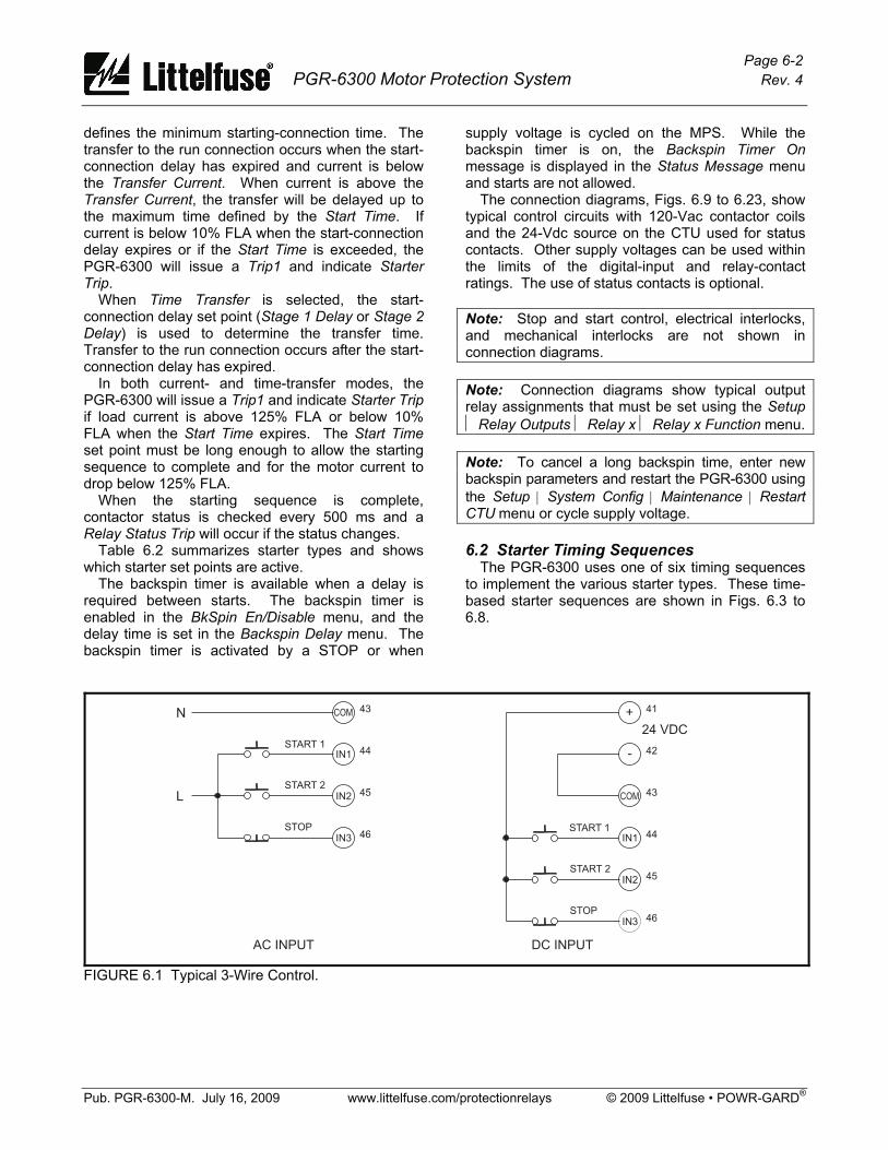
Page 6-2 PGR-6300 Motor Protection System Rev. 4
Pub. PGR-6300-M. July 16, 2009 www.littelfuse.com/protectionrelays © 2009 Littelfuse • POWR-GARD®
defines the minimum starting-connection time. The transfer to the run connection occurs when the start-connection delay has expired and current is below the Transfer Current. When current is above the Transfer Current, the transfer will be delayed up to the maximum time defined by the Start Time. If current is below 10% FLA when the start-connection delay expires or if the Start Time is exceeded, the PGR-6300 will issue a Trip1 and indicate Starter Trip. When Time Transfer is selected, the start-connection delay set point (Stage 1 Delay or Stage 2 Delay) is used to determine the transfer time. Transfer to the run connection occurs after the start-connection delay has expired. In both current- and time-transfer modes, the PGR-6300 will issue a Trip1 and indicate Starter Trip if load current is above 125% FLA or below 10% FLA when the Start Time expires. The Start Time set point must be long enough to allow the starting sequence to complete and for the motor current to drop below 125% FLA. When the starting sequence is complete, contactor status is checked every 500 ms and a Relay Status Trip will occur if the status changes. Table 6.2 summarizes starter types and shows which starter set points are active. The backspin timer is available when a delay is required between starts. The backspin timer is enabled in the BkSpin En/Disable menu, and the delay time is set in the Backspin Delay menu. The backspin timer is activated by a STOP or when
supply voltage is cycled on the MPS. While the backspin timer is on, the Backspin Timer On message is displayed in the Status Message menu and starts are not allowed. The connection diagrams, Figs. 6.9 to 6.23, show typical control circuits with 120-Vac contactor coils and the 24-Vdc source on the CTU used for status contacts. Other supply voltages can be used within the limits of the digital-input and relay-contact ratings. The use of status contacts is optional. Note: Stop and start control, electrical interlocks, and mechanical interlocks are not shown in connection diagrams. Note: Connection diagrams show typical output relay assignments that must be set using the Setup ⏐ Relay Outputs ⏐ Relay x ⏐ Relay x Function menu. Note: To cancel a long backspin time, enter new backspin parameters and restart the PGR-6300 using the Setup | System Config | Maintenance | Restart CTU menu or cycle supply voltage. 6.2 Starter Timing Sequences The PGR-6300 uses one of six timing sequences to implement the various starter types. These time-based starter sequences are shown in Figs. 6.3 to 6.8.
L
N
IN2
IN3
IN2
IN3
IN1
IN1
-
+COM
COM45
46
45
46
44
44
43
43
42
41
AC INPUT DC INPUT
START 1
START 1
START 2
STOP
24 VDC
START 2
STOP
FIGURE 6.1 Typical 3-Wire Control.

Page 6-3 PGR-6300 Motor Protection System Rev. 4
Pub. PGR-6300-M. July 16, 2009 www.littelfuse.com/protectionrelays © 2009 Littelfuse • POWR-GARD®
L
N
IN2
IN2
IN1
IN1
-
+COM
COM45
45
44
44
43
43
42
41
AC INPUT DC INPUT
START 1
START 1
START 2
START 2
24 VDC
FIGURE 6.2 Typical 2-Wire Control.
TABLE 6.2 Starter Summary
SEQ.
TIMERS
START- CONNECTION
ACTIVE FLA SETPOINTS (2)
RELAYS AND CONTACTOR STATUS (3)
STARTER TYPE NO. USED (1) TIMER NUMBER (1)
FLA FLA 2 RLYA RLYB RLYC RLYD
Full-Voltage Non-Reversing 1 4 x x Adjustable-Speed Drive 1 4 x x Soft-Start 1 4 x x Full-Voltage Reversing 2 4 x x x Two-Speed Two-Winding 2 4 x x x x Reactor or Resistor Closed-Transition (4)
3 1,4 1 x x x
Slip-Ring (4) 3 1,4 1 x x x Part-Winding (4) 3 1,4 1 x x x x Double-Delta (4) 3 1,4 1 x x x x Soft-Start-with-Bypass (4) 3 1,4 1 x x x Reactor or Resistor Open-Transition (4)
4 1,4 1 x x x
Two-Winding (4) 4 1,4 1 x x x x Wye-Delta Open-Transition (4)
5 1,2,3,4 2 x x x x x
Autotransformer Closed-Transition (4)
5 1,2,3,4 2 x x x x
Wye-Delta Closed-Transition (4)
6 1,2,4 2 x x x x x x
(1) TIMERS 1: Stage 1 Delay 2: Stage 2 Delay 3: Stage 3 Delay 4: Start Time
(2) FLA SETPOINTS FLA: Full-Load Current FLA2: Full-Load Current 2
(3) RELAYS AND CONTACTOR STATUS Starter RLYA, Starter RLYB, Starter RLYC, and Starter RLYD are not automatically assigned. The user must assign these functions to individual relays. Status is assignable to any digital input.
(4) Current transfer capability when enabled.

Page 6-4 PGR-6300 Motor Protection System Rev. 4
Pub. PGR-6300-M. July 16, 2009 www.littelfuse.com/protectionrelays © 2009 Littelfuse • POWR-GARD®
FIGURE 6.3 Starter Sequence 1.
FIGURE 6.4 Starter Sequence 2.
START1/START2
Stage1 Delay
Starter RLYA
Start Time
Starter RLYB
Transition may be delayedif is enabled.Current Transfer
FIGURE 6.5 Starter Sequence 3.
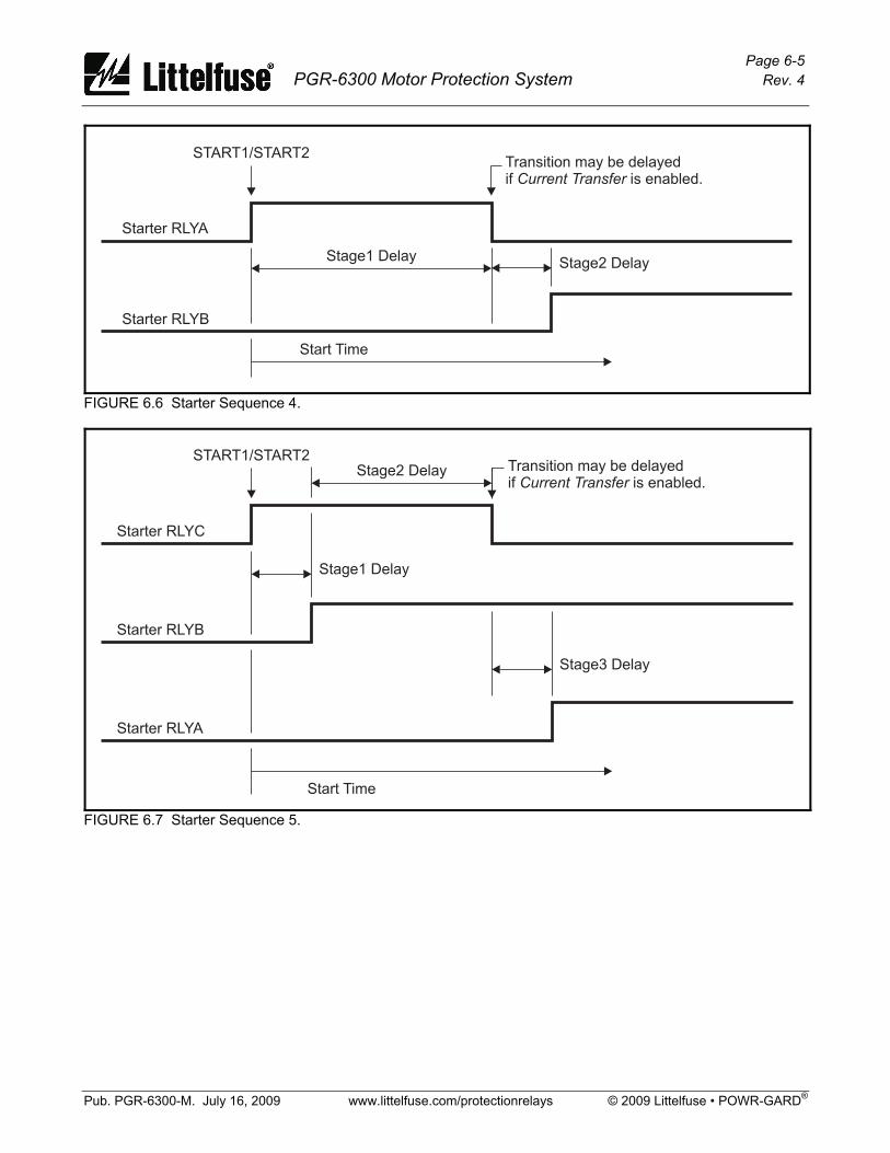
Page 6-5 PGR-6300 Motor Protection System Rev. 4
Pub. PGR-6300-M. July 16, 2009 www.littelfuse.com/protectionrelays © 2009 Littelfuse • POWR-GARD®
START1/START2
Starter RLYA
Stage1 DelayStage2 Delay
Starter RLYB
Start Time
Transition may be delayedif is enabled.Current Transfer
FIGURE 6.6 Starter Sequence 4.
START1/START2
Stage1 Delay
Stage3 Delay
Stage2 Delay
Starter RLYC
Starter RLYA
Start Time
Starter RLYB
Transition may be delayedif is enabled.Current Transfer
FIGURE 6.7 Starter Sequence 5.

Page 6-6 PGR-6300 Motor Protection System Rev. 4
Pub. PGR-6300-M. July 16, 2009 www.littelfuse.com/protectionrelays © 2009 Littelfuse • POWR-GARD®
START1/START2
Starter RLYC
Stage1 Delay Stage1 Delay
Stage1 DelayStage1 Delay
Stage2 Delay
Starter RLYA
Starter RLYD
Start Time
Starter RLYB
Transition may be delayedif is enabled.Current Transfer
FIGURE 6.8 Starter Sequence 6. 6.3 Full-Voltage Non-Reversing Starter Sequence: Fig. 6.3 Connection: Fig. 6.9 Current Transfer: Not available
START1 or START2 is the start command and Starter RLYA is used as the output to control the contactor.
FIGURE 6.9 Full-Voltage Non-Reversing-Starter Connection.
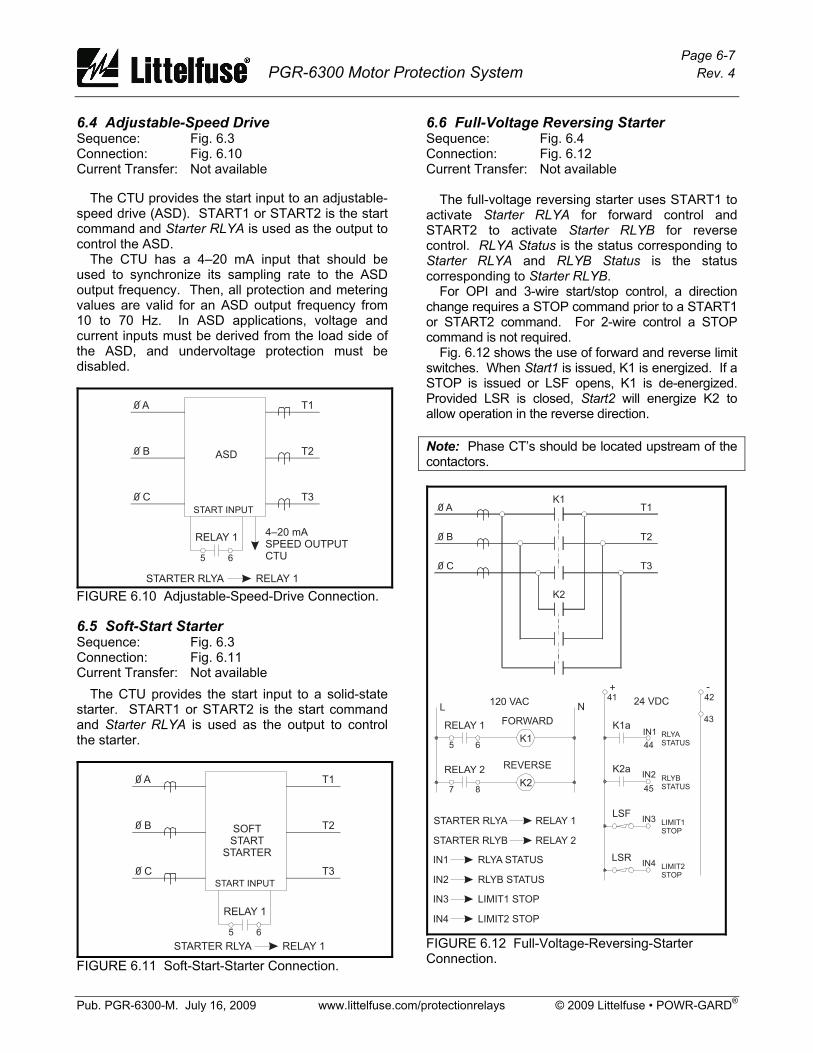
Page 6-7 PGR-6300 Motor Protection System Rev. 4
Pub. PGR-6300-M. July 16, 2009 www.littelfuse.com/protectionrelays © 2009 Littelfuse • POWR-GARD®
6.4 Adjustable-Speed Drive Sequence: Fig. 6.3 Connection: Fig. 6.10 Current Transfer: Not available The CTU provides the start input to an adjustable-speed drive (ASD). START1 or START2 is the start command and Starter RLYA is used as the output to control the ASD. The CTU has a 4–20 mA input that should be used to synchronize its sampling rate to the ASD output frequency. Then, all protection and metering values are valid for an ASD output frequency from 10 to 70 Hz. In ASD applications, voltage and current inputs must be derived from the load side of the ASD, and undervoltage protection must be disabled.
0 A
0 B
0 C
T1
T2
T3
RELAY 1
5 6
RELAY 1STARTER RLYA
ASD
START INPUT
4–20 mASPEED OUTPUTCTU
FIGURE 6.10 Adjustable-Speed-Drive Connection. 6.5 Soft-Start Starter Sequence: Fig. 6.3 Connection: Fig. 6.11 Current Transfer: Not available
The CTU provides the start input to a solid-state starter. START1 or START2 is the start command and Starter RLYA is used as the output to control the starter.
0 A
0 B
0 C
T1
T2
T3
RELAY 1
5 6
RELAY 1STARTER RLYA
SOFTSTART
STARTER
START INPUT
FIGURE 6.11 Soft-Start-Starter Connection.
6.6 Full-Voltage Reversing Starter Sequence: Fig. 6.4 Connection: Fig. 6.12 Current Transfer: Not available The full-voltage reversing starter uses START1 to activate Starter RLYA for forward control and START2 to activate Starter RLYB for reverse control. RLYA Status is the status corresponding to Starter RLYA and RLYB Status is the status corresponding to Starter RLYB. For OPI and 3-wire start/stop control, a direction change requires a STOP command prior to a START1 or START2 command. For 2-wire control a STOP command is not required. Fig. 6.12 shows the use of forward and reverse limit switches. When Start1 is issued, K1 is energized. If a STOP is issued or LSF opens, K1 is de-energized. Provided LSR is closed, Start2 will energize K2 to allow operation in the reverse direction. Note: Phase CT’s should be located upstream of the contactors.
0 A
0 B
0 C
K1
K2
T1
T2
T3
L N
K1
K2
RELAY 1 FORWARD
REVERSERELAY 2
K1a
K2a
5
7
6
8
44
45
41 42
43
RELAY 1
RLYA STATUS
RELAY 2
RLYB STATUS
STARTER RLYA
IN1
STARTER RLYB
IN2
24 VDC120 VAC
+ -
RLYASTATUS
RLYBSTATUS
IN1
IN2
LIMIT1 STOP
LIMIT2 STOP
IN3
IN4
LSFLIMIT1STOP
IN3
LSRLIMIT2STOP
IN4
FIGURE 6.12 Full-Voltage-Reversing-Starter Connection.
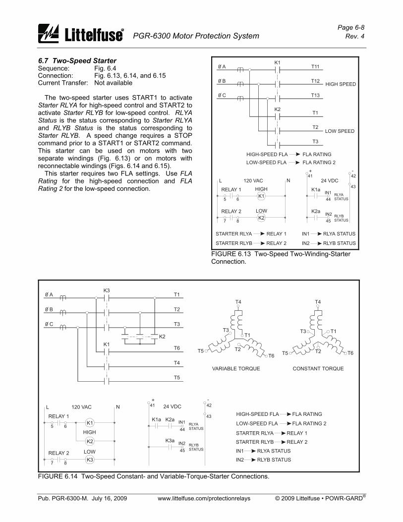
Page 6-8 PGR-6300 Motor Protection System Rev. 4
Pub. PGR-6300-M. July 16, 2009 www.littelfuse.com/protectionrelays © 2009 Littelfuse • POWR-GARD®
6.7 Two-Speed Starter Sequence: Fig. 6.4 Connection: Fig. 6.13, 6.14, and 6.15 Current Transfer: Not available The two-speed starter uses START1 to activate Starter RLYA for high-speed control and START2 to activate Starter RLYB for low-speed control. RLYA Status is the status corresponding to Starter RLYA and RLYB Status is the status corresponding to Starter RLYB. A speed change requires a STOP command prior to a START1 or START2 command. This starter can be used on motors with two separate windings (Fig. 6.13) or on motors with reconnectable windings (Figs. 6.14 and 6.15). This starter requires two FLA settings. Use FLA Rating for the high-speed connection and FLA Rating 2 for the low-speed connection.
FIGURE 6.13 Two-Speed Two-Winding-Starter Connection.
FIGURE 6.14 Two-Speed Constant- and Variable-Torque-Starter Connections.
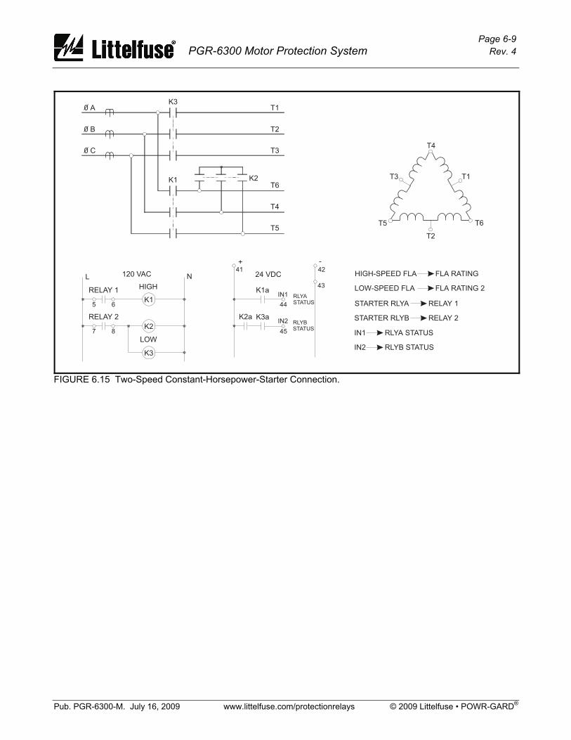
Page 6-9 PGR-6300 Motor Protection System Rev. 4
Pub. PGR-6300-M. July 16, 2009 www.littelfuse.com/protectionrelays © 2009 Littelfuse • POWR-GARD®
FIGURE 6.15 Two-Speed Constant-Horsepower-Starter Connection.
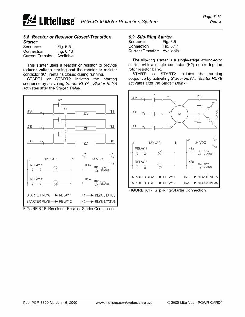
Page 6-10 PGR-6300 Motor Protection System Rev. 4
Pub. PGR-6300-M. July 16, 2009 www.littelfuse.com/protectionrelays © 2009 Littelfuse • POWR-GARD®
6.8 Reactor or Resistor Closed-Transition Starter Sequence: Fig. 6.5 Connection: Fig. 6.16 Current Transfer: Available This starter uses a reactor or resistor to provide reduced-voltage starting and the reactor or resistor contactor (K1) remains closed during running. START1 or START2 initiates the starting sequence by activating Starter RLYA. Starter RLYB activates after the Stage1 Delay.
FIGURE 6.16 Reactor or Resistor-Starter Connection.
6.9 Slip-Ring Starter Sequence: Fig. 6.5 Connection: Fig. 6.17 Current Transfer: Available The slip-ring starter is a single-stage wound-rotor starter with a single contactor (K2) controlling the rotor resistor bank. START1 or START2 initiates the starting sequence by activating Starter RLYA. Starter RLYB activates after the Stage1 Delay.
FIGURE 6.17 Slip-Ring-Starter Connection.

Page 6-11 PGR-6300 Motor Protection System Rev. 4
Pub. PGR-6300-M. July 16, 2009 www.littelfuse.com/protectionrelays © 2009 Littelfuse • POWR-GARD®
6.10 Part-Winding And Double-Delta Starter Sequence: Fig. 6.5 Connection: Fig. 6.18 Current Transfer: Available The part-winding starter is used on motors with two stator windings and the double-delta starter has a delta winding that is parallel connected during running. START1 or START2 initiates the starting sequence by activating Starter RLYA. Starter RLYB activates after the Stage1 Delay. Both starters require two FLA settings. FLA Rating 2 is the full-load current for the starting connection and FLA Rating is the full-load current for the running connection.
FIGURE 6.18 Part-Winding and Double-Delta-Starter Connections.
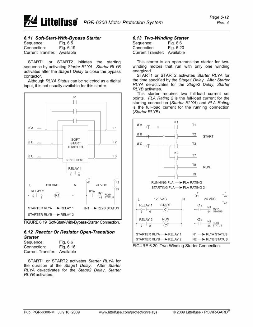
Page 6-12 PGR-6300 Motor Protection System Rev. 4
Pub. PGR-6300-M. July 16, 2009 www.littelfuse.com/protectionrelays © 2009 Littelfuse • POWR-GARD®
6.11 Soft-Start-With-Bypass Starter Sequence: Fig. 6.5 Connection: Fig. 6.19 Current Transfer: Available START1 or START2 initiates the starting sequence by activating Starter RLYA. Starter RLYB activates after the Stage1 Delay to close the bypass contactor. Although RLYA Status can be selected as a digital input, it is not usually available for this starter.
FIGURE 6.19 Soft-Start-With-Bypass-Starter Connection. 6.12 Reactor Or Resistor Open-Transition Starter Sequence: Fig. 6.6 Connection: Fig. 6.16 Current Transfer: Available START1 or START2 activates Starter RLYA for the duration of the Stage1 Delay. After Starter RLYA de-activates for the Stage2 Delay, Starter RLYB activates.
6.13 Two-Winding Starter Sequence: Fig. 6.6 Connection: Fig. 6.20 Current Transfer: Available This starter is an open-transition starter for two-winding motors that run with only one winding energized. START1 or START2 activates Starter RLYA for the time specified by the Stage1 Delay. After Starter RLYA de-activates for the Stage2 Delay, Starter RLYB activates. This starter requires two full-load current set points. FLA Rating 2 is the full-load current for the starting connection (Starter RLYA) and FLA Rating is the full-load current for the running connection (Starter RLYB).
FIGURE 6.20 Two-Winding-Starter Connection.
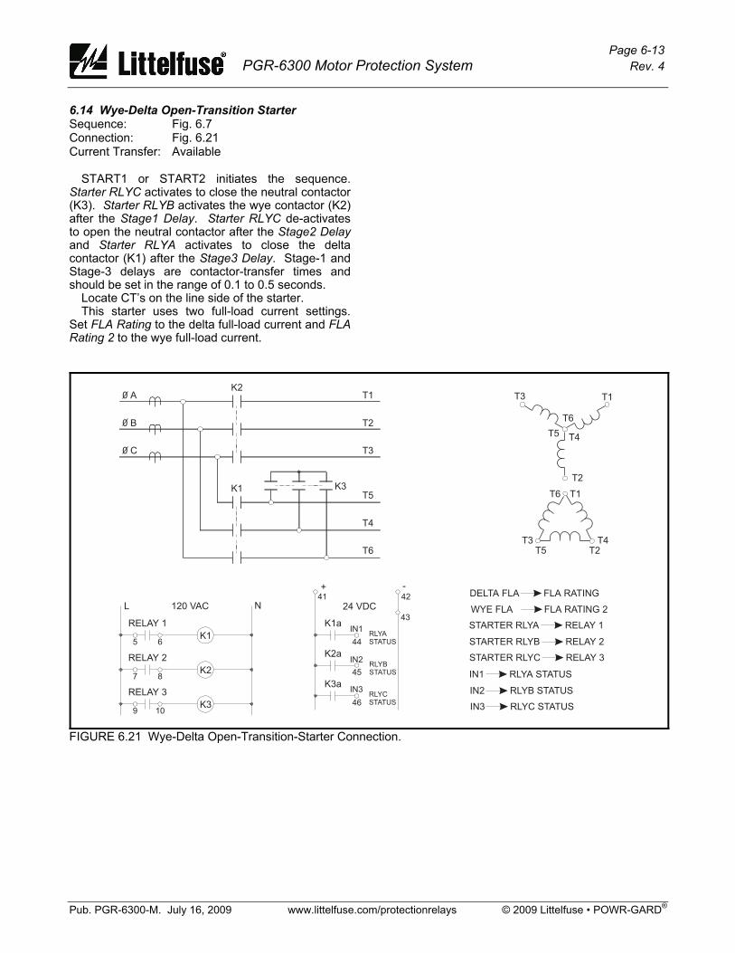
Page 6-13 PGR-6300 Motor Protection System Rev. 4
Pub. PGR-6300-M. July 16, 2009 www.littelfuse.com/protectionrelays © 2009 Littelfuse • POWR-GARD®
6.14 Wye-Delta Open-Transition Starter Sequence: Fig. 6.7 Connection: Fig. 6.21 Current Transfer: Available START1 or START2 initiates the sequence. Starter RLYC activates to close the neutral contactor (K3). Starter RLYB activates the wye contactor (K2) after the Stage1 Delay. Starter RLYC de-activates to open the neutral contactor after the Stage2 Delay and Starter RLYA activates to close the delta contactor (K1) after the Stage3 Delay. Stage-1 and Stage-3 delays are contactor-transfer times and should be set in the range of 0.1 to 0.5 seconds. Locate CT’s on the line side of the starter. This starter uses two full-load current settings. Set FLA Rating to the delta full-load current and FLA Rating 2 to the wye full-load current.
FIGURE 6.21 Wye-Delta Open-Transition-Starter Connection.
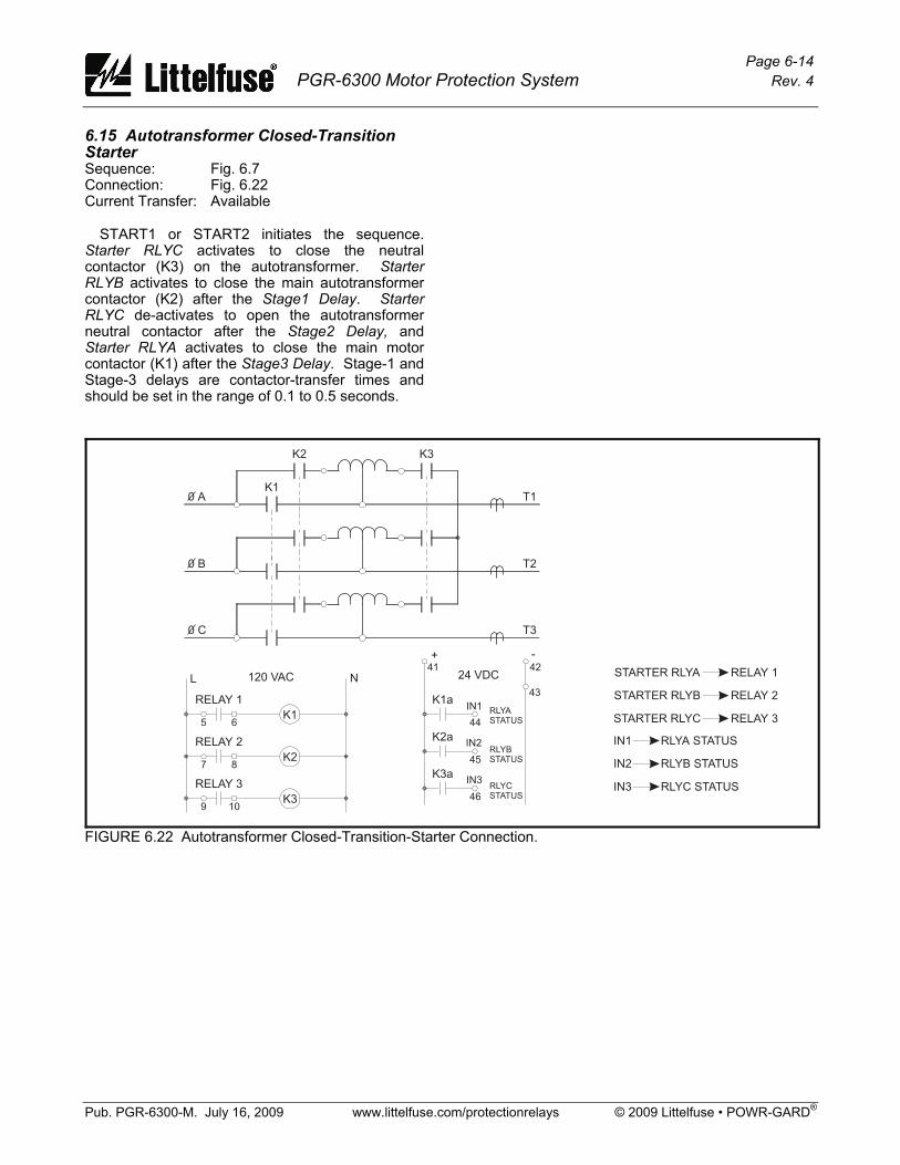
Page 6-14 PGR-6300 Motor Protection System Rev. 4
Pub. PGR-6300-M. July 16, 2009 www.littelfuse.com/protectionrelays © 2009 Littelfuse • POWR-GARD®
6.15 Autotransformer Closed-Transition Starter Sequence: Fig. 6.7 Connection: Fig. 6.22 Current Transfer: Available START1 or START2 initiates the sequence. Starter RLYC activates to close the neutral contactor (K3) on the autotransformer. Starter RLYB activates to close the main autotransformer contactor (K2) after the Stage1 Delay. Starter RLYC de-activates to open the autotransformer neutral contactor after the Stage2 Delay, and Starter RLYA activates to close the main motor contactor (K1) after the Stage3 Delay. Stage-1 and Stage-3 delays are contactor-transfer times and should be set in the range of 0.1 to 0.5 seconds.
FIGURE 6.22 Autotransformer Closed-Transition-Starter Connection.
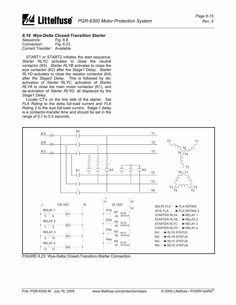
Page 6-15 PGR-6300 Motor Protection System Rev. 4
Pub. PGR-6300-M. July 16, 2009 www.littelfuse.com/protectionrelays © 2009 Littelfuse • POWR-GARD®
6.16 Wye-Delta Closed-Transition Starter Sequence: Fig. 6.8 Connection: Fig. 6.23 Current Transfer: Available START1 or START2 initiates the start sequence. Starter RLYC activates to close the neutral contactor (K3). Starter RLYB activates to close the wye contactor (K2) after the Stage1 Delay. Starter RLYD activates to close the resistor contactor (K4) after the Stage2 Delay. This is followed by de-activation of Starter RLYC, activation of Starter RLYA to close the main motor contactor (K1), and de-activation of Starter RLYD, all displaced by the Stage1 Delay. Locate CT’s on the line side of the starter. Set FLA Rating to the delta full-load current and FLA Rating 2 to the wye full-load current. Stage-1 delay is a contactor-transfer time and should be set in the range of 0.1 to 0.5 seconds.
FIGURE 6.23 Wye-Delta Closed-Transition-Starter Connection.

Page 6-16 PGR-6300 Motor Protection System Rev. 4
Pub. PGR-6300-M. July 16, 2009 www.littelfuse.com/protectionrelays © 2009 Littelfuse • POWR-GARD®
This page intentionally left blank.

Page 7-1 PGR-6300 Motor Protection System Rev. 4
Pub. PGR-6300-M. July 16, 2009 www.littelfuse.com/protectionrelays © 2009 Littelfuse • POWR-GARD®
7. THEORY OF OPERATION 7.1 Signal-Processing Algorithms The sampling frequency of the PGR-6300 is variable. It can be set for 50-Hz, 60-Hz, or variable-frequency applications. The PGR-6300 obtains sixteen samples per cycle of each current and voltage signal. For an adjustable-speed drive (ASD) application, a speed or frequency output from the ASD can be connected to the 4–20-mA input to synchronize the sampling rate to the ASD output frequency. This maintains accurate measurements of power and sequential components. The sampling rate is sixteen samples per cycle of the fundamental frequency. A Discrete-Fourier-Transform (DFT) algorithm is used to obtain the magnitude and phase angles of the fundamental-frequency components of the current and voltage waveforms. These values provide true positive- and negative-sequence components. True RMS values of line currents are calculated for use by the thermal-model algorithm. RMS values include up to the 8th harmonic. All calculated values are updated at the sampling frequency to achieve a fast response to fault conditions. RMS values of the fundamental components of current and voltage are displayed. The PGR-6300 uses the input voltage VA for frequency measurement. The input voltage must be above 30 Vac and a sixteen-cycle interval is used to determine frequency. Frequency protection is inhibited when system voltage is less than 50% of the System Voltage setting. 7.2 Power Algorithm Apparent power (S) is calculated by:
jQPS += Real power (P) is determined from the in-phase components of I and V, and reactive power (Q) is determined from the quadrature components of I with respect to V. Power factor is the magnitude of the ratio of P to S. The one-PT connection assumes balanced voltages for power calculations. Power calculations for the other connections are valid for both balanced and unbalanced conditions. In all cases, power calculations use the two-wattmeter method and assume three-wire loads.
The IEEE convention is used for power displays: +Watts, +Vars, -PF (Lag) Importing Watts,
Importing Vars +Watts, -Vars, +PF (Lead) Importing Watts,
Exporting Vars -Watts, -Vars, -PF (Lag) Exporting Watts,
Exporting Vars -Watts, +Vars, +PF (Lead) Exporting Watts,
Importing Vars 7.3 OPERATOR INTERFACE (OPI) The OPI is a terminal device used to communicate with the CTU. All set points, operating parameters, and menus are stored in the CTU. The OPI contains a microprocessor used to communicate with the CTU, read key presses, and perform display functions. On multiple-OPI systems, all OPI’s display the same information. Key presses on any OPI will be processed by the CTU. 7.4 PGA-0120 Temperature Input Module The PGA-0120 contains a microprocessor, A/D converter, and analog multiplexers used to measure up to eight RTD’s. The RTD-measuring circuit is isolated from the I/O Module network. All eight RTD’s are scanned every three seconds. RTD linearization, open/short detection, and lead compensation are performed by the PGA-0120. RTD temperature is sent to the CTU where temperature monitoring occurs. 7.5 PGA-0140 Differential Current Module The PGA-0140 obtains 32 samples per cycle of the differential current. A Discrete-Fourier-Transform (DFT) algorithm is used to obtain the magnitude of the three differential currents. Frequency of operation is set by the CTU and allows differential protection to be used in variable-frequency drive applications. The DFT values are sent to the CTU where differential protection is performed.
Page 7-2 PGR-6300 Motor Protection System Rev. 4
Pub. PGR-6300-M. July 16, 2009 www.littelfuse.com/protectionrelays © 2009 Littelfuse • POWR-GARD®
7.6 Firmware Diagnostics Starting with firmware 2.01, diagnostic error handling has been added. In the event of an internal fault, a diagnostic error code is generated and can be viewed with the OPI. The last error code can be viewed by selecting Setup ⏐ System Config ⏐ Maintenance ⏐ Firmware Version. The diagnostic code is a two or three digit hexadecimal number. 02 to FF: Processor Fault 100: Protection Algorithm Fault 200: Relay-Control Algorithm Fautlt 300: Starter-Control Fault 400: Menu Display Fault 500: OPI Key Handler Fault 600: Real-Time Clock Fault 700: Communication-Handler Fault 800: RTD Temperature-Handler Fault 900: A/D Communication-Interface Fault The last diagnostic error code is saved in non-volatile memory. The diagnostic code is overwritten by any new codes but can also be manually set to zero. To clear the error code, press RESET while in the Firmware Version menu. When upgrading a PGR-6300 that did not previously support the diagnostic error code, the initial value of the diagnostic code is not valid and should be cleared. A diagnostic error generates a Trip1 and increments the trip counter, however, a trip record is not generated.

Page 8-1 PGR-6300 Motor Protection System Rev. 4
Pub. PGR-6300-M. July 16, 2009 www.littelfuse.com/protectionrelays © 2009 Littelfuse • POWR-GARD®
8. COMMUNICATIONS 8.1 Personal-Computer Interface 8.1.1 Firmware Upgrade The CTU control program is stored in flash memory. Field updates can be made through the I/O module communications connection. The following are required: • A Windows® PC, with the PGW-FLSH program
installed, • a file containing the CTU control program
(.s19 file), and • an RS-232/RS-485 converter that operates at
57,600 bit/s (such as the PGA-0400). PGW-FLSH is available at
www.littelfuse.com/protectionrelays. 8.1.2 PGW-COMM PGW-COMM is a Windows-based program used to access PGR-6300 functions with a personal computer (PC) via the RS-485 network interface or Modbus® TCP. Use PGW-COMM to program a PGR-6300 either by changing individual set points or by downloading set-point files. Existing PGR-6300 set points can be transferred to the PC. Metered values can be viewed and the PGR-6300 can be controlled with the computer. PGW-COMM extends the event-record storage capability of the PGR-6300 by allowing the user to transfer data to PC memory at a programmable interval. Protection curve plotting capability is included. PGW-COMM is available at www.littelfuse.com/protectionrelays. 8.2 Network Interface For detailed information see Appendices to this manual and applicable communications manuals. 8.2.1 RS-485 Communications RS-485 communications support Modbus® RTU and Allen-Bradley® DF1 half-duplex protocols. All set points and meter values are accessible. Commands are provided to perform trips, resets, and starter control. Modbus® RTU function codes supported: • Read Holding Registers (Code 3) • Read Input Registers (Code 4) • Write Single Register (Code 6) • Write Multiple Registers (Code 16) • Command Instruction (Code 5)
DF1 Commands Supported: • Unprotected Read (CMD = 01) • Unprotected Write (CMD = 08) • Typed Read (CMD = 0F, FNC = 68) • Typed Write (CMD = 0F, FNC = 67) • Typed Logical Read (CMD = 0F, FNC = A2) • Typed Logical Write (CMD = 0F, FNC = AA) 8.2.2 DeviceNet Communications DeviceNetTM communications support Explicit Messaging and Polled I/O. All set points and meter values are accessible using Explicit Messaging. The Polled I/O connection supports the following ODVA input assemblies: • Basic Overload (50) • Extended Overload (51) • Basic Motor Starter (52) • Extended Motor Starter 1 (53) • Extended Motor Starter 2 (53) In addition to the ODVA assemblies, a user-configurable fixed block of 64 bytes is available. The Polled I/O connection supports the following ODVA output assemblies: • Basic Overload (2) • Basic Motor Starter (3) • Extended Contactor • Extended Motor Starter An Electronic Data Sheet (EDS) file is provided for use with DeviceNet configuration tools such as RSNetWorx and DeltaV. 8.2.3 Ethernet Communications The PGR-6300 supports Modbus® TCP and Ethernet/IP using the Anybus-S module from HMS Fieldbus Systems AB. Data from the PGR-6300 consists of a 64-byte assembly representing user-defined register data. A command structure is provided to write set-point and PGR-6300 commands. Starting with firmware 2.50, Modbus® TCP provides access to all PGR-6300 registers and supports PGW-COMM. 8.2.4 Profibus DP Communications The PGR-6300 supports Profibus-DP using the Anybus-S module. Data from the PGR-6300 consists of a 64-byte assembly representing user-defined register data. A command structure is provided to write set-point and PGR-6300 commands.

Page 8-2 PGR-6300 Motor Protection System Rev. 4
Pub. PGR-6300-M. July 16, 2009 www.littelfuse.com/protectionrelays © 2009 Littelfuse • POWR-GARD®
This page intentionally left blank.

Page 9-1 PGR-6300 Motor Protection System Rev. 4
Pub. PGR-6300-M. July 16, 2009 www.littelfuse.com/protectionrelays © 2009 Littelfuse • POWR-GARD®
9. TECHNICAL SPECIFICATIONS 9.1 Control Unit (CTU) Supply.................................25 VA, 65 to 265 Vac, 40 to 400 Hz, power
factor corrected. 25 W, 80 to 275 Vdc. Power-Up Time ..................800 ms at 120 Vac Ride-Through Time ............100 ms minimum 24-Vdc Source (1)................100 mA maximum AC Measurements: Methods.........................True RMS and DFT. Positive- and negative-
sequence components of the fundamental.
Sample Rate .................16 samples/cycle Frequency: Fixed..............................50, 60 Hz, Variable .........................10 to 70 Hz, sync via 4–20 mA signal from ASD Phase-Current Inputs: (2) Range............................18 x CT-Primary Rating (Ip) Accuracy: (3) I < Ip..........................1% Ip I > Ip..........................1% Reading Burden...........................< 0.01 Ω Unbalance Accuracy .....0.01 pu Common-Mode Voltage..120 Vac maximum Thermal Withstand: Continuous...............5 x CT Rating 1-Second..................80 x CT Rating Earth-Leakage Input: Range............................1.5 x Earth-Fault-CT-
Primary Rating (Ie) Accuracy (3)....................1% Ie Burden...........................< 0.01 Ω (1- and 5-A
inputs), 10 Ω for PGC Common-Mode Voltage..120 Vac maximum Thermal Withstand: Continuous...............5 x CT Rating 1-Second..................80 x CT Rating
Phase-Voltage Inputs: (4, 5) Nominal Input................30 to 600 Vac line-to-line Input Resistance ...........3.4 MΩ Range............................1.4 x PT-Primary Rating (Vp) Accuracy: (3) V < Vp.......................1% Vp V > Vp.......................1% Reading Unbalance Accuracy .....0.01 pu Frequency Metering: Range............................5 to 100 Hz Uses VA input, Sine wave assumed Accuracy .......................0.05 Hz PTC-Thermistor Input: (1) Cold Resistance............1500 Ω maximum at 20°C Trip Level ......................2800 Ω ± 100 Ω Sensor Current..............2 mA maximum 4–20 mA Analog Input: Input Burden .................100 Ω Common-Mode Voltage (6) ...................± 5 Vdc 4–20 mA Analog Output: (1) Load ..............................500 Ω maximum Range............................0 to 25 mA Update Time .................500 ms Tachometer Input: (7) Type ..............................Active pickup, 24-V logic
output, sourcing, PNP output. TURCK Bi1.5-EG08-AP6X-V1131 or equivalent
Pulses Per Revolution...1 to 100 Pulse Frequency ...........10 Hz to 10 kHz Accuracy .......................1% Delay Timer Accuracies: (8) Minimum Delay .............Set point –10% Maximum Delay ............Set point +35 ms Starter-Control Stop Time: Digital Input ...................30 to 80 ms OPI ................................70 to 200 ms Network.........................30 to 80 ms
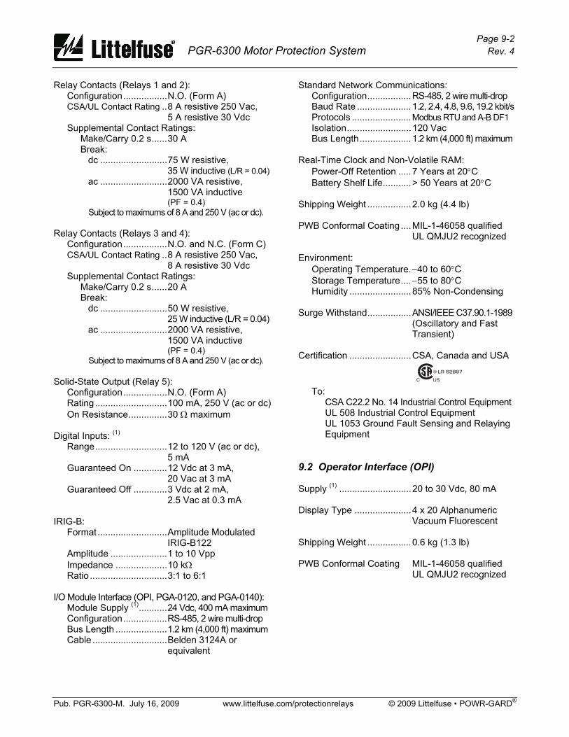
Page 9-2 PGR-6300 Motor Protection System Rev. 4
Pub. PGR-6300-M. July 16, 2009 www.littelfuse.com/protectionrelays © 2009 Littelfuse • POWR-GARD®
Relay Contacts (Relays 1 and 2): Configuration.................N.O. (Form A) CSA/UL Contact Rating ..8 A resistive 250 Vac, 5 A resistive 30 Vdc Supplemental Contact Ratings: Make/Carry 0.2 s......30 A Break: dc ..........................75 W resistive, 35 W inductive (L/R = 0.04) ac ..........................2000 VA resistive, 1500 VA inductive (PF = 0.4) Subject to maximums of 8 A and 250 V (ac or dc). Relay Contacts (Relays 3 and 4): Configuration.................N.O. and N.C. (Form C) CSA/UL Contact Rating ..8 A resistive 250 Vac, 8 A resistive 30 Vdc Supplemental Contact Ratings: Make/Carry 0.2 s......20 A Break: dc ..........................50 W resistive, 25 W inductive (L/R = 0.04) ac ..........................2000 VA resistive, 1500 VA inductive (PF = 0.4) Subject to maximums of 8 A and 250 V (ac or dc). Solid-State Output (Relay 5): Configuration.................N.O. (Form A) Rating............................100 mA, 250 V (ac or dc) On Resistance...............30 Ω maximum Digital Inputs: (1) Range............................12 to 120 V (ac or dc),
5 mA Guaranteed On .............12 Vdc at 3 mA, 20 Vac at 3 mA Guaranteed Off .............3 Vdc at 2 mA, 2.5 Vac at 0.3 mA IRIG-B: Format ...........................Amplitude Modulated
IRIG-B122 Amplitude ......................1 to 10 Vpp Impedance ....................10 kΩ Ratio ..............................3:1 to 6:1 I/O Module Interface (OPI, PGA-0120, and PGA-0140): Module Supply (1)...........24 Vdc, 400 mA maximum Configuration.................RS-485, 2 wire multi-drop Bus Length ....................1.2 km (4,000 ft) maximum Cable .............................Belden 3124A or
equivalent
Standard Network Communications: Configuration.................RS-485, 2 wire multi-drop Baud Rate .....................1.2, 2.4, 4.8, 9.6, 19.2 kbit/s Protocols .......................Modbus RTU and A-B DF1 Isolation.........................120 Vac Bus Length....................1.2 km (4,000 ft) maximum Real-Time Clock and Non-Volatile RAM: Power-Off Retention .....7 Years at 20°C Battery Shelf Life...........> 50 Years at 20°C Shipping Weight .................2.0 kg (4.4 lb) PWB Conformal Coating ....MIL-1-46058 qualified
UL QMJU2 recognized Environment: Operating Temperature.−40 to 60°C Storage Temperature....−55 to 80°C Humidity ........................85% Non-Condensing Surge Withstand.................ANSI/IEEE C37.90.1-1989 (Oscillatory and Fast
Transient) Certification ........................CSA, Canada and USA
To: CSA C22.2 No. 14 Industrial Control Equipment UL 508 Industrial Control Equipment UL 1053 Ground Fault Sensing and Relaying Equipment 9.2 Operator Interface (OPI) Supply (1) ............................20 to 30 Vdc, 80 mA Display Type ......................4 x 20 Alphanumeric
Vacuum Fluorescent Shipping Weight .................0.6 kg (1.3 lb) PWB Conformal Coating MIL-1-46058 qualified
UL QMJU2 recognized
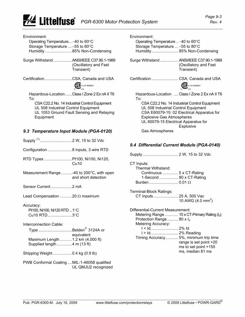
Page 9-3 PGR-6300 Motor Protection System Rev. 4
Pub. PGR-6300-M. July 16, 2009 www.littelfuse.com/protectionrelays © 2009 Littelfuse • POWR-GARD®
Environment: Operating Temperature...−40 to 60°C Storage Temperature ....−55 to 80°C Humidity ........................85% Non-Condensing Surge Withstand.................ANSI/IEEE C37.90.1-1989 (Oscillatory and Fast
Transient) Certification.........................CSA, Canada and USA
Hazardous-Location ......Class I Zone 2 Ex nA II T6 To: CSA C22.2 No. 14 Industrial Control Equipment UL 508 Industrial Control Equipment UL 1053 Ground Fault Sensing and Relaying Equipment 9.3 Temperature Input Module (PGA-0120) Supply (1).............................2 W, 15 to 32 Vdc Configuration ......................8 inputs, 3 wire RTD RTD Types .........................Pt100, Ni100, Ni120,
Cu10 Measurement Range..........-40 to 200°C, with open
and short detection Sensor Current ...................2 mA Lead Compensation ...........20 Ω maximum Accuracy: Pt100, Ni100, Ni120 RTD...1°C Cu10 RTD......................3°C Interconnection Cable: Type ..............................Belden® 3124A or equivalent Maximum Length ...........1.2 km (4,000 ft) Supplied length..............4 m (13 ft) Shipping Weight .................0.4 kg (0.9 lb) PWB Conformal Coating ....MIL-1-46058 qualified UL QMJU2 recognized
Environment: Operating Temperature .. −40 to 60°C Storage Temperature ... −55 to 80°C Humidity........................ 85% Non-Condensing Surge Withstand ................ ANSI/IEEE C37.90.1-1989 (Oscillatory and Fast
Transient) Certification ........................ CSA, Canada and USA
Hazardous-Location .... Class I Zone 2 Ex nA II T6 To: CSA C22.2 No. 14 Industrial Control Equipment UL 508 Industrial Control Equipment CSA E60079-15: 02 Electrical Apparatus for Explosive Gas Atmospheres UL 60079-15 Electrical Apparatus for
Explosive Gas Atmospheres 9.4 Differential Current Module (PGA-0140) Supply ................................ 2 W, 15 to 32 Vdc CT Inputs: Thermal Withstand: Continuous .............. 5 x CT-Rating 1-Second ................. 80 x CT-Rating Burden .......................... 0.01 Ω Terminal-Block Ratings: CT Inputs ...................... 25 A, 500 Vac 10 AWG (4.0 mm2) Differential-Current Measurement: Metering Range ............ 15 x CT-Primary Rating (Id) Protection Range.......... 80 x Id Metering Accuracy: I < Id......................... 2% Id I > Id......................... 2% Reading Timing Accuracy ........... 5%, minimum trip time
range is set point +20 ms to set point +150 ms, median 81 ms

Page 9-4 PGR-6300 Motor Protection System Rev. 4
Pub. PGR-6300-M. July 16, 2009 www.littelfuse.com/protectionrelays © 2009 Littelfuse • POWR-GARD®
Interconnection Cable: Type ..............................Belden® 3124A or equivalent Maximum Length...........1.2 km (4,000 ft) Shipping Weight .................0.4 kg (0.9 lb) PWB Conformal Coating ....MIL-1-46058 qualified
UL QMJU2 recognized Environment: Operating Temperature...−40 to 60°C Storage Temperature ....−55 to 80°C Humidity ........................85% Non-Condensing Surge Withstand.................ANSI/IEEE C37.90.1-1989 (Oscillatory and Fast
Transient) Notes: (1) The I/O module supply (terminal 56), PTC
(terminal 54), AN OUT (terminal 40), and 24-Vdc source (terminal 42) are referenced to the same common.
(2) Current threshold is a function of full-load current and CT-Primary Rating and given by:
FLA
RatingPrimary CT x 1.5 Threshold Percent =
Power readings are not displayed for currents below this threshold. To maintain specified accuracy, phase CT's should be selected with a primary rating between 100% and 300% of motor full-load current.
(3) Transformer accuracy not included. (4) Voltage unbalance is not displayed for positive-
sequence voltage levels below 20% of system voltage setting.
(5) Direct connection for system voltages up to 600 Vac line-to-line.
(6) Common-mode voltage relative to CTU terminal 3.
(7) Referenced to COM. (8) Also see Tables 5.1, 5.2, and PGA-0140 accuracy.

Page A-1 PGR-6300 Motor Protection System Rev. 4
Pub. PGR-6300-M. July 16, 2009 www.littelfuse.com/protectionrelays © 2009 Littelfuse • POWR-GARD®
APPENDIX A PGR-6300 MENU MAP
Legend:
[x] Enter numeric[s] Enter string[E/D] Enable/Disable[TA] Trip Action: Disable; Trip1; Trip2; Trip3[AA] Alarm Action: Disable; Alarm1;
Alarm2; Alarm3[EA] Ethernet Address
I/O STATUS
Analog Input
Digital Input States
Output Relay States
SYSTEM STATE
COMM STATE
Starter State(Stop/Run/Start)
Motor State(Stop/Run/Start)
Motor Speed
(METERING Continued)
RTD TEMPERATURE
Summary (Max/Min)
RTD Module 1 to 3RTD #1 to 8
Stator
RTD Identification
Bearing
Function
Load
Temp./Messages
�
�
MAIN MENU
CURRENT
UNBALANCE (I)
+ Sequence
- Sequence
Unbalance
UNBALANCE (V)
+ Sequence
- Sequence
Unbalance
METERING �
IaIbIc
THERMAL CAPACITY
Used I²t
Reset Time
Trend I²t
Trip Time
Inhibit Time
EARTH LEAKAGE
Ig
POWER
Real (P)
Apparent (S)
Reactive (Q)
Power Factor
ENERGY
FREQUENCY
Kilowatt-hours
Frequency: Hz
Kilovolt-ampere-hours
Kilovar-hours
VOLTAGE
Vab
Vbc
Vca
(METERING Continued)
Notes:
List indicates possible trips and alarms.
Password required.
List does not match PGR-6300 menu order.
Password is required and the set point islocked when the motor is running.
RTD Module = Temperature Input ModulePGA-0120.
DIF Module = Differential Current ModulePGA-0140.
(1)
(2)
(3)
(4)
Starts Available
DIFFERENTIAL (A)
IaIbIc
Reduced OC(On/Off)
(5)
(6)
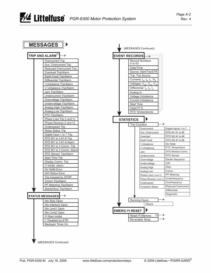
Page A-2 PGR-6300 Motor Protection System Rev. 4
Pub. PGR-6300-M. July 16, 2009 www.littelfuse.com/protectionrelays © 2009 Littelfuse • POWR-GARD®
STATISTICS
Trip Counters
Overcurrent
Undervoltage
I Unbalance
V Unbalance
Phase Loss (I and V)
Phase Reverse (I and V)
Aux. Overcurrent
Analog High
Jam RTD Module Comm
OPI
RTD Sensor
Stop
Comm
Underfrequency
PF Motoring
Overfrequency
Digital Inputs 1 to 7
RTD M3 #1 to #8
Overload
Analog Low
Undercurrent
RTD M1 #1 to #8
NV RAM
Earth Fault
PTC Temperature
Starter SequenceOvervoltage
Underspeed
Contactor Status
RTD M2 #1 to #8
�
Hours
Running Hours
EMERG I²t RESET
Reset I²t Memory
Re-enable Temp.
(2)�
TRIP AND ALARM
Overcurrent Trip
Aux. Overcurrent Trip
I Unbalance Trip/Alarm
Undercurrent Trip/Alarm
Analog Low Trip/Alarm
Overload Trip/Alarm
V Unbalance Trip/Alarm
Undervoltage Trip/Alarm
Overvoltage Trip/Alarm
PTC Trip/Alarm
Phase Loss Trip (I and V)
Earth-Fault Trip/Alarm
Jam Trip/Alarm
Analog High Trip/Alarm
Start Time Trip
RTD M1 to 3 #1-8 Trip
RTD M1 to 3 Comm. Alarm
RTD Sensor Trip/Alarm
Display Comm. Trip
I t Inhibit Alarm2
RTD M1 to 3 #1-8 Alarm
Digital Input 1 to 7 Trip
RTD M1 to 3 Comm. Trip
Relay Status Trip
Underspeed Trip
Phase Reverse (I and V)
NV RAM Error
A/D Status Error
Trip Caused by STOP
Comm Trip/Alarm
PF Motoring Trip/Alarm
MESSAGES
(1)
�
STATUS MESSAGES
INx Stop Open
INx Interlock Open
I²t Start Inhibit
t° Disabled by ETR
Backspin Timer On
EVENT RECORDS
Record Numbers0 to 63
Trip: Trip Source
Current Unbalance
RTD Temperatures
Start Time
Differential: I , I , Ia b c
Voltage Unbalance
Date/Time
Used I²t %
Source: Start/Trip/ETR
Voltages: V , V , Vab bc ca
Currents: I , I , I , 3Ia b c 0
(MESSAGES Continued)
(MESSAGES Continued)
Starts/Hour Trip/Alarm
INx Limit1 Open
INx Limit2 Open
Analog In
Reduced Overcurrent Trip
Differential Trip/Alarm
Reduced Overcurrent
Differential
Diagnostic
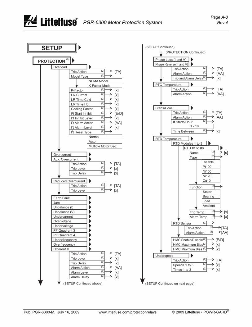
Page A-3 PGR-6300 Motor Protection System Rev.4
Pub. PGR-6300-M. July 16, 2009 www.littelfuse.com/protectionrelays © 2009 Littelfuse • POWR-GARD®
(PROTECTION Continued)
PROTECTION
Overload
Trip Action
Model Type
NEMA Model
K-Factor Model
SETUP
(2)
(2)
(3)
�
�
�
LR Time Hot
K-Factor
Cooling Factor
I²t Start Inhibit
LR Current
I²t Inhibit Level
LR Time Cold
I t Alarm Level2
I t Alarm Action2
(2)
(2)
(2)
(2)
(2)
(2)
(2)
(2)
(2)
[x]
[x]
[x]
[x]
[x]
[E/D]
[x]
[x]
[AA]
Aux. Overcurrent
Overcurrent
Trip Action
Trip Level
Trip Delay
(2)
(2)
(2)
��
[x]
[x]
[TA]
[TA]
Underfrequency
Overfrequency�
Jam
Unbalance (I)
Unbalance (V)
Earth Fault
Undervoltage
PF Quadrant 3
PF Quadrant 4
Undercurrent
Overvoltage
���
������
�
Trip Action
Alarm Action
(2)
(2)
Trip Level
Alarm Level
Trip Delay
Alarm Delay
(2)
(2)
(2)
(2)
[x]
[x]
[x]
[x]
[TA]
[AA]
Phase Loss (I and V)
Phase Reverse (I and V)
Trip Action
Alarm Action
Trip and Alarm Delay
(2)
(2)
(2)
��
[AA]
[x]
[TA]
PTC Temperature
Trip Action
Alarm Action
(2)
(2)
�[TA]
[AA]
RTD Temperature
RTD Modules 1 to 3�
�RTD #1 to #8
�Name
Type
Disable
Pt100
Ni100
Ni120
Cu10
Bearing
Load
Ambient
Function
Trip Temp.
Alarm Temp.
(2)
(2)
(2)
(2)
(2)
[x]
[s]
[x]
RTD Sensor (2)
Underspeed
Speeds 1 to 3
Trip Action
Times 1 to 3
(2)
(2)
(2)
�
[x]
[x]
[TA]
HMC Enable/Disable
HMC Maximum Bias
HMC Minimum Bias
(2)
(2)
(2) [x]
[x]
[E/D]
(SETUP Continued above)
Starts/Hour
Alarm Action
Trip Action
Time Between
(2)
(2)
(2)
�
[x]
[AA]
[TA]
# Starts/Hour (2)
1 - 10
(SETUP Continued)
(SETUP Continued on next page)
Alarm Action
Trip Action (2)
(2) [AA]
[TA]
Stator
I t Reset Type2 (2)
Normal
Auto
Multiple Motor Seq.
Differential�
Reduced Overcurrent
Trip Action
Trip Level
(2)
(2)
�
[x]
[TA]
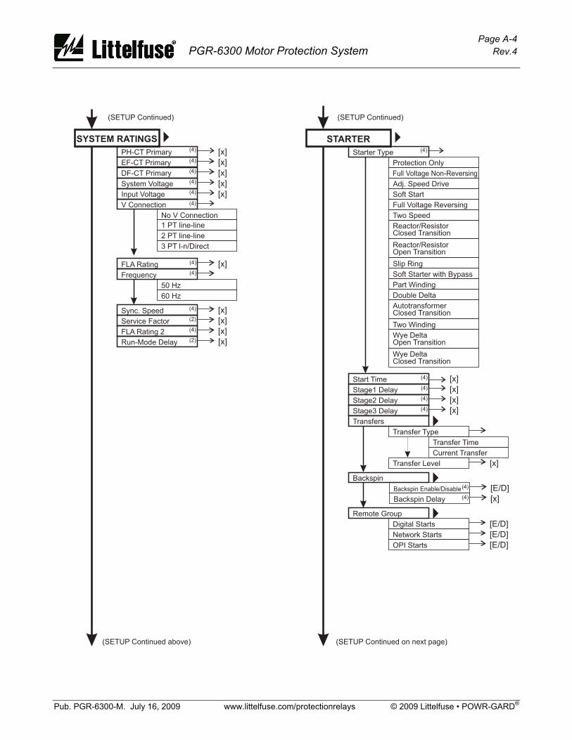
Page A-4 PGR-6300 Motor Protection System Rev.4
Pub. PGR-6300-M. July 16, 2009 www.littelfuse.com/protectionrelays © 2009 Littelfuse • POWR-GARD®
AutotransformerClosed Transition
Wye DeltaOpen Transition
Wye DeltaClosed Transition
Two Winding
Double Delta
Slip Ring
Soft Starter with Bypass
Part Winding
Full Voltage Non-Reversing
Full Voltage Reversing
Transfer Time
Current Transfer
(4)
(4)
[E/D]
[x]
[x]
(SETUP Continued on next page)
STARTER
Starter Type
Protection Only
Adj. Speed Drive
Soft Start
Two Speed
Reactor/ResistorClosed Transition
Reactor/ResistorOpen Transition
(4)�
Start Time
Stage1 Delay
Stage2 Delay
Stage3 Delay
Transfers
Backspin
(4)
(4)
(4)
(4)
[x]
[x]
[x]
[x]
Transfer Type
Transfer Level
�
�Backspin Enable/Disable
Backspin Delay
FLA Rating
Frequency
50 Hz
60 Hz
(4)
(4)
[x]
Sync. Speed
Service Factor
FLA Rating 2
Run-Mode Delay
(4)
(2)
(2)
(4) [x]
[x]
[x]
[x]
(SETUP Continued)
SYSTEM RATINGS
PH-CT Primary
EF-CT Primary
System Voltage
Input Voltage
(4)
(4)
(4)
(4)
V Connection
No V Connection
1 PT line-line
2 PT line-line
3 PT l-n/Direct
(4)
�
[x]
[x]
[x]
[x]
(SETUP Continued above)
(SETUP Continued)
Digital Starts
Network Starts
OPI Starts
�Remote Group
[E/D]
[E/D]
[E/D]
DF-CT Primary (4) [x]
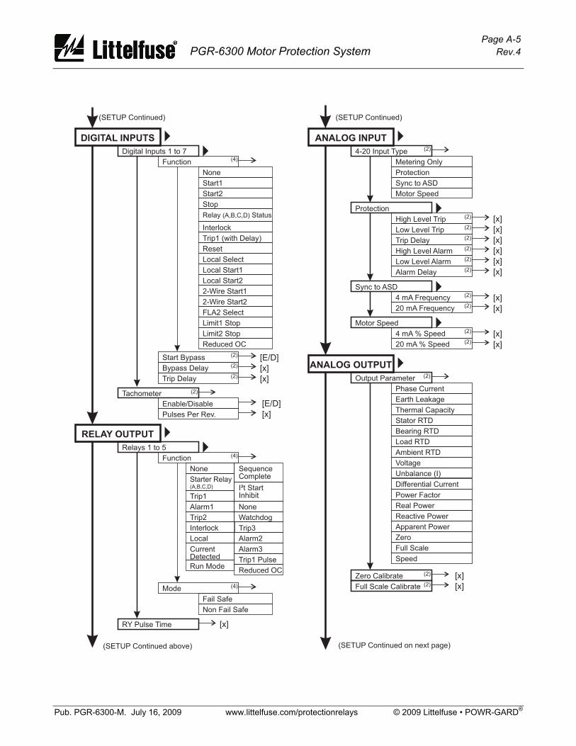
Page A-5 PGR-6300 Motor Protection System Rev.4
Pub. PGR-6300-M. July 16, 2009 www.littelfuse.com/protectionrelays © 2009 Littelfuse • POWR-GARD®
(SETUP Continued)
ANALOG OUTPUT
Output Parameter
Zero Calibrate
Full Scale Calibrate
Phase Current
Earth Leakage
Bearing RTD
Thermal Capacity
Load RTD
Stator RTD
Ambient RTD
Power Factor
Apparent Power
Voltage
Real Power
Zero
Unbalance (I)
Reactive Power
Full Scale
(2)
(2)
(2)
�
[x]
[x]
(SETUP Continued on next page)
4 mA % Speed
20 mA % Speed
(2)
(2)
�[x]
[x]
ANALOG INPUT �4-20 Input Type
Metering Only
Protection
Sync to ASD
Motor Speed
(2)
Protection
Sync to ASD
Motor Speed
High Level Trip
4 mA Frequency
High Level Alarm
Low Level Trip
20 mA Frequency
Low Level Alarm
Trip Delay
Alarm Delay
(2)
(2)
(2)
(2)
(2)
(2)
(2)
(2)
�
�
[x]
[x]
[x]
[x]
[x]
[x]
[x]
[x]
Speed
RELAY OUTPUT
Relays 1 to 5
RY Pulse Time
Function
None
Starter Relay(A,B,C,D)
Alarm1
Trip1
Trip2
Trip3
Alarm3
Trip1 Pulse
Alarm2
(4)
I²t StartInhibit
Interlock
Local
CurrentDetected
Run Mode
SequenceComplete
None
Watchdog
Mode
Fail Safe
Non Fail Safe
(4)
�
�
DIGITAL INPUTS
Digital Inputs 1 to 7
Function
None
Relay (A,B,C,D) Status
Start1
Interlock
Start2
Stop
Trip1 (with Delay)
Reset
Local Select
Local Start1
2-Wire Start1
Local Start2
2-Wire Start2
(4)�
�
Start Bypass
Bypass Delay
Trip Delay
(2)
(2)
(2) [x]
[x]
[E/D]
Enable/Disable
Pulses Per Rev.
Tachometer (2)
[E/D]
[x]
[x]
(SETUP Continued)
(SETUP Continued above)
Limit1 Stop
FLA2 Select
Limit2 Stop
Reduced OC
Reduced OC
Differential Current
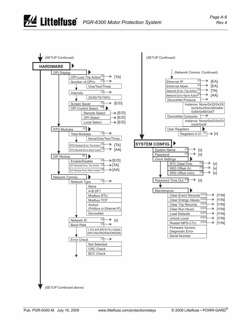
Page A-6 PGR-6300 Motor Protection System Rev.4
Pub. PGR-6300-M. July 16, 2009 www.littelfuse.com/protectionrelays © 2009 Littelfuse • POWR-GARD®
SYSTEM CONFIG.
System Name
Password
Clock Settings
(2)
(2)
�
RTC Date/Time
IRIG Offset (h)
IRIG Offset (min)
(2)
(2)
(2)
[x]
[x]
[x]
Password Time Out (2) [x]
Maintenance
Clear Event Records
Clear Trip Records
Clear Run Hours
Load Defaults
Unlock Local
Restart MPS-CTU
Firmware Version,Diagnostic Error
(2)(4)
(2)(4)
(2)(4)
(2)(4)
(2)(4)
(2)(4)
�
�
[ ]Y/N
Clear Energy Values (2)(4) [ ]Y/N
[ ]Y/N
[ ]Y/N
[ ]Y/N
[ ]Y/N
[ ]Y/N
[s]
[s]
(SETUP Continued)
HARDWARE �OPI Display
One/Two/Three
25/50/75/100%
Remote Select
OPI Select
Local Select
Number of OPI’s
Intensity
OPI Control Select
OPI-Loss Trip Action(2)
(2)
(2)
(2)�
�
[TA]
[E/D]
[E/D]
[E/D]
(2)
(2)
(2)
RTD Modules
Total Modules
RTD-Module-Error Trip Action
RTD-Module-Error Alarm Action
None/One/Two/Three
�
[TA]
[AA]
(SETUP Continued)
(2)
Network Comms.
Network Type
None
A-B DF1
Modbus RTU
DeviceNet
�
(2)
(2)
(2)
(2)
(2)Baud Rate
Error Check
Network-Error Trip Action
Network-Error Alarm Action
1.2/2.4/4.8/9.6/19.2 kbit/sDN125k/DN250k/DN500k
Not Selected
CRC Check
BCC Check
Network ID
(2)
User Registers�
[x]
[TA]
[AA]
(SETUP Continued above)
Screen Saver(2) [E/D]
Registers 0-31 [x]
DIF Module
Enable/Disable� [E/D]
[TA]
[AA]
(2)
(2)
(2)
DeviceNet Produce
Instance: None/0x32/0x33/0x34/0x35/0x36/0x64/0x65/0x66/0x67
DeviceNet Consume
Instance: None/0x02/0x03/0x04/0x05
Serial Number
(Network Comms. Continued)
DIF-Module-Error Trip Action
DIF-Module-Error Alarm Action
(2) [EA]
(2)Ethernet IP [EA]
Ethernet Mask
Anybus(Profibus or Ethernet IP)
Modbus TCP
(5)
(6)
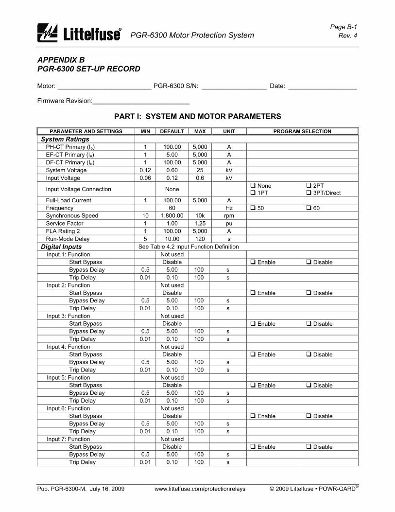
Page B-1 PGR-6300 Motor Protection System Rev. 4
Pub. PGR-6300-M. July 16, 2009 www.littelfuse.com/protectionrelays © 2009 Littelfuse • POWR-GARD®
APPENDIX B PGR-6300 SET-UP RECORD
Motor: __________________________ PGR-6300 S/N: __________________ Date: ___________________
Firmware Revision:___________________________
PART I: SYSTEM AND MOTOR PARAMETERS
PARAMETER AND SETTINGS MIN DEFAULT MAX UNIT PROGRAM SELECTION System Ratings
PH-CT Primary (Ip) 1 100.00 5,000 A EF-CT Primary (Ie) 1 5.00 5,000 A DF-CT Primary (Id) 1 100.00 5,000 A System Voltage 0.12 0.60 25 kV Input Voltage 0.06 0.12 0.6 kV
Input Voltage Connection None None 1PT
2PT 3PT/Direct
Full-Load Current 1 100.00 5,000 A Frequency 60 Hz 50 60 Synchronous Speed 10 1,800.00 10k rpm Service Factor 1 1.00 1.25 pu FLA Rating 2 1 100.00 5,000 A Run-Mode Delay 5 10.00 120 s
Digital Inputs See Table 4.2 Input Function Definition Input 1: Function Not used
Start Bypass Disable Enable Disable Bypass Delay 0.5 5.00 100 s Trip Delay 0.01 0.10 100 s
Input 2: Function Not used Start Bypass Disable Enable Disable Bypass Delay 0.5 5.00 100 s Trip Delay 0.01 0.10 100 s
Input 3: Function Not used Start Bypass Disable Enable Disable Bypass Delay 0.5 5.00 100 s Trip Delay 0.01 0.10 100 s
Input 4: Function Not used Start Bypass Disable Enable Disable Bypass Delay 0.5 5.00 100 s Trip Delay 0.01 0.10 100 s
Input 5: Function Not used Start Bypass Disable Enable Disable Bypass Delay 0.5 5.00 100 s Trip Delay 0.01 0.10 100 s
Input 6: Function Not used Start Bypass Disable Enable Disable Bypass Delay 0.5 5.00 100 s Trip Delay 0.01 0.10 100 s
Input 7: Function Not used Start Bypass Disable Enable Disable Bypass Delay 0.5 5.00 100 s Trip Delay 0.01 0.10 100 s
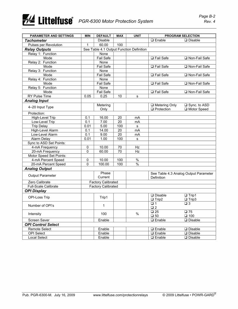
Page B-2 PGR-6300 Motor Protection System Rev. 4
Pub. PGR-6300-M. July 16, 2009 www.littelfuse.com/protectionrelays © 2009 Littelfuse • POWR-GARD®
PARAMETER AND SETTINGS MIN DEFAULT MAX UNIT PROGRAM SELECTION Tachometer Disable Enable Disable
Pulses per Revolution 1 60.00 100 Relay Outputs See Table 4.1 Output Function Definition
Relay 1: Function None Mode Fail Safe Fail Safe Non-Fail Safe
Relay 2: Function None Mode Fail Safe Fail Safe Non-Fail Safe
Relay 3: Function None Mode Fail Safe Fail Safe Non-Fail Safe
Relay 4: Function None Mode Fail Safe Fail Safe Non-Fail Safe
Relay 5: Function None Mode Fail Safe Fail Safe Non-Fail Safe
RY Pulse Time 0.05 0.25 10 s Analog Input
4–20 Input Type Metering Only Metering Only
Protection Sync. to ASD Motor Speed
Protection: High-Level Trip 0.1 16.00 20 mA Low-Level Trip 0.1 7.00 20 mA Trip Delay 0.01 5.00 100 s High-Level Alarm 0.1 14.00 20 mA Low-Level Alarm 0.1 9.00 20 mA Alarm Delay 0.01 1.00 100 s
Sync to ASD Set Points: 4-mA Frequency 0 10.00 70 Hz 20-mA Frequency 0 60.00 70 Hz
Motor Speed Set Points: 4-mA Percent Speed 0 10.00 100 % 20-mA Percent Speed 0 100.00 100 %
Analog Output
Output Parameter Phase Current See Table 4.3 Analog Output Parameter
Definition Zero Calibrate Factory Calibrated Full-Scale Calibrate Factory Calibrated
OPI Display OPI-Loss Trip Trip1 Disable
Trip2 Trip1 Trip3
Number of OPI’s 1 1 2
3
Intensity 100 % 25 50
75 100
Screen Saver Enable Enable Disable OPI Control Select
Remote Select Enable Enable Disable OPI Select Enable Enable Disable Local Select Enable Enable Disable
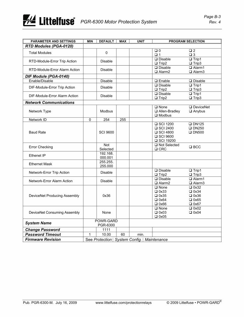
Page B-3 PGR-6300 Motor Protection System Rev. 4
Pub. PGR-6300-M. July 16, 2009 www.littelfuse.com/protectionrelays © 2009 Littelfuse • POWR-GARD®
PARAMETER AND SETTINGS MIN DEFAULT MAX UNIT PROGRAM SELECTION
RTD Modules (PGA-0120) Total Modules 0 0
1 2 3
RTD-Module-Error Trip Action Disable Disable Trip2
Trip1 Trip3
RTD-Module-Error Alarm Action Disable Disable Alarm2
Alarm1 Alarm3
DIF Module (PGA-0140) Enable/Disable Disable Enable Disable
DIF-Module-Error Trip Action Disable Disable Trip2
Trip1 Trip3
DIF-Module-Error Alarm Action Disable Disable Trip2
Trip1 Trip3
Network Communications
Network Type Modbus None Allen-Bradley Modbus
DeviceNet Anybus
Network ID 0 254 255
Baud Rate SCI 9600
SCI 1200 SCI 2400 SCI 4800 SCI 9600 SCI 19200
DN125 DN250 DN500
Error Checking Not Selected Not Selected
CRC BCC
Ethenet IP 192.168. 000.001
Ethernet Mask 255.255. 255.000
Network-Error Trip Action Disable Disable Trip2
Trip1 Trip3
Network-Error Alarm Action Disable Disable Alarm2
Alarm1 Alarm3
DeviceNet Producing Assembly 0x36
None 0x33 0x35 0x64 0x66
0x32 0x34 0x36 0x65 0x67
DeviceNet Consuming Assembly None None 0x03 0x05
0x02 0x04
System Name POWR-GARD PGR-6300
Change Password 1111 Password Timeout 1 10.00 60 min. Firmware Revision See Protection | System Config. | Maintenance
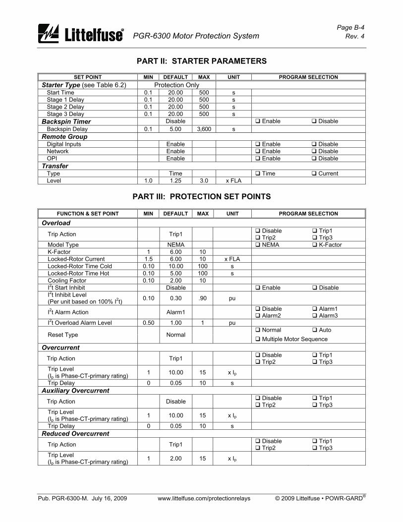
Page B-4 PGR-6300 Motor Protection System Rev. 4
Pub. PGR-6300-M. July 16, 2009 www.littelfuse.com/protectionrelays © 2009 Littelfuse • POWR-GARD®
PART II: STARTER PARAMETERS
SET POINT MIN DEFAULT MAX UNIT PROGRAM SELECTION Starter Type (see Table 6.2) Protection Only
Start Time 0.1 20.00 500 s Stage 1 Delay 0.1 20.00 500 s Stage 2 Delay 0.1 20.00 500 s Stage 3 Delay 0.1 20.00 500 s
Backspin Timer Disable Enable Disable Backspin Delay 0.1 5.00 3,600 s
Remote Group Digital Inputs Enable Enable Disable Network Enable Enable Disable OPI Enable Enable Disable
Transfer Type Time Time Current Level 1.0 1.25 3.0 x FLA
PART III: PROTECTION SET POINTS
FUNCTION & SET POINT MIN DEFAULT MAX UNIT PROGRAM SELECTION
Overload
Trip Action Trip1 Disable Trip2
Trip1 Trip3
Model Type NEMA NEMA K-Factor K-Factor 1 6.00 10 Locked-Rotor Current 1.5 6.00 10 x FLA Locked-Rotor Time Cold 0.10 10.00 100 s Locked-Rotor Time Hot 0.10 5.00 100 s Cooling Factor 0.10 2.00 10 I2t Start Inhibit Disable Enable Disable I2t Inhibit Level (Per unit based on 100% I2t) 0.10 0.30 .90 pu
I2t Alarm Action Alarm1 Disable Alarm2
Alarm1 Alarm3
I2t Overload Alarm Level 0.50 1.00 1 pu Normal Auto
Reset Type Normal Multiple Motor Sequence
Overcurrent Trip Action Trip1 Disable
Trip2 Trip1 Trip3
Trip Level (Ip is Phase-CT-primary rating) 1 10.00 15 x Ip
Trip Delay 0 0.05 10 s Auxiliary Overcurrent
Trip Action Disable Disable Trip2
Trip1 Trip3
Trip Level (Ip is Phase-CT-primary rating) 1 10.00 15 x Ip
Trip Delay 0 0.05 10 s Reduced Overcurrent
Trip Action Trip1 Disable Trip2
Trip1 Trip3
Trip Level (Ip is Phase-CT-primary rating) 1 2.00 15 x Ip

Page B-5 PGR-6300 Motor Protection System Rev. 4
Pub. PGR-6300-M. July 16, 2009 www.littelfuse.com/protectionrelays © 2009 Littelfuse • POWR-GARD®
FUNCTION & SET POINT MIN DEFAULT MAX UNIT PROGRAM SELECTION
Earth Fault Trip Action Trip1 Disable
Trip2 Trip1 Trip3
Trip Level (Ie is EF-CT-primary rating) 0.05 0.40 1 x Ie
Trip Delay 0 0.25 100 s
Alarm Action Alarm1 Disable Alarm2
Alarm1 Alarm3
Alarm Level 0.05 0.20 1 x Ie Alarm Delay 0 1.00 100 s
Jam Trip Action Trip1 Disable
Trip2 Trip1 Trip3
Trip Level 1 6.00 10 x FLA Trip Delay 1 5.00 100 s
Alarm Action Alarm1 Disable Alarm2
Alarm1 Alarm3
Alarm Level 1 3.00 10 x FLA Alarm Delay 1 5.00 100 s
Unbalance (I) Trip Action Trip1 Disable
Trip2 Trip1 Trip3
Trip Level (Per unit based on I2/I1) 0.05 0.25 1 pu
Trip Delay 1 15.00 100 s
Alarm Action Alarm1 Disable Alarm2
Alarm1 Alarm3
Alarm Level 0.05 0.10 1 pu Alarm Delay 1 10.00 100 s
Phase Loss (I) Trip Action Trip1 Disable
Trip2 Trip1 Trip3
Phase Loss Delay 1 5.00 100 s Phase Reverse (I)
Trip Action Disable Disable Trip2
Trip1 Trip3
Alarm Action Alarm1 Disable Alarm2
Alarm1 Alarm3
Trip and Alarm Delay 1 2.00 100 s Unbalance (V)
Trip Action Trip1 Disable Trip2
Trip1 Trip3
Trip Level (Per unit based on V2/V1)
0.05 0.10 1 pu
Trip Delay 1 15.00 100 s
Alarm Action Alarm1 Disable Alarm2
Alarm1 Alarm3
Alarm Level 0.05 0.05 1 pu Alarm Delay 1 10.00 100 s
Phase Loss (V)
Trip Action Disable Disable Trip2
Trip1 Trip3
Phase Loss Delay 1 5.00 100 s

Page B-6 PGR-6300 Motor Protection System Rev. 4
Pub. PGR-6300-M. July 16, 2009 www.littelfuse.com/protectionrelays © 2009 Littelfuse • POWR-GARD®
FUNCTION & SET POINT MIN DEFAULT MAX UNIT PROGRAM SELECTION
Phase Reverse (V) Trip Action Disable Disable
Trip2 Trip1 Trip3
Alarm Action Alarm1 Disable Alarm2
Alarm1 Alarm3
Phase Reverse Trip and Alarm Delay 1 2.00 100 s
Undercurrent Trip Action Disable Disable
Trip2 Trip1 Trip3
Trip Level 0.1 0.50 1 x FLA Trip Delay 1 10.00 100 s
Alarm Action Disable Disable Alarm2
Alarm1 Alarm3
Alarm Level 0.1 0.80 1 x FLA Alarm Delay 1 20.00 100 s
Differential (PGA-0140) Trip Action Disable Disable
Trip2 Trip1 Trip3
Trip Level (Id is DF-CT-Primary Current) 0.1 1.00 15 x Id
Trip Delay 0 0.10 10 s
Alarm Action Disable Disable Alarm2
Alarm1 Alarm3
Alarm Level 0.1 0.50 15 x Id Alarm Delay 0 0.10 10 s
PF Quadrant 4 Trip Action Disable Disable
Trip2 Trip1 Trip3
Trip Level 0.5 0.80 1 Trip Delay 0.1 5.00 500 s
Alarm Action Disable Disable Alarm2
Alarm1 Alarm3
Alarm Level 0.5 0.90 1 Alarm Delay 0.1 5.00 500 s
PF Quadrant 3
Trip Action Disable Disable Trip2
Trip1 Trip3
Trip Level 0.5 0.80 1 Trip Delay 0.1 5.00 500 s
Alarm Action Disable Disable Alarm2
Alarm1 Alarm3
Alarm Level 0.5 0.90 1 Alarm Delay 0.1 5.00 500 s
Underfrequency
Trip Action Disable Disable Trip2
Trip1 Trip3
Trip Level 30 45 80 Hz Trip Delay 0.5 5 500 s
Alarm Action Disable Disable Alarm2
Alarm1 Alarm3
Alarm Level 30 48 80 Hz Alarm Delay 0.5 1 500 s

Page B-7 PGR-6300 Motor Protection System Rev. 4
Pub. PGR-6300-M. July 16, 2009 www.littelfuse.com/protectionrelays © 2009 Littelfuse • POWR-GARD®
FUNCTION & SET POINT MIN DEFAULT MAX UNIT PROGRAM SELECTION
Overfrequency Trip Action Disable Disable
Trip2 Trip1 Trip3
Trip Level 30 65 80 Hz Trip Delay 0.5 5 500 s
Alarm Action Disable Disable Alarm2
Alarm1 Alarm3
Alarm Level 30 62 80 Hz Alarm Delay 0.5 1 500 s
PTC Temperature Trip Action Disable Disable
Trip2 Trip1 Trip3
Alarm Action Disable Disable Alarm2
Alarm1 Alarm3
RTD-Sensor-Error Trip Action Disable Disable Trip2
Trip1 Trip3
RTD-Sensor-Error Alarm Action Alarm1 Disable
Alarm2 Alarm1 Alarm3
Hot-Motor Compensation (HMC) Disable Enable Disable
HMC High 40 150.00 200 °C HMC Low 40 40.00 200 °C
Acceleration Failure—Underspeed
Trip Action Disable Disable Trip2
Trip1 Trip3
Speed 1 (Percent Sync Speed) 1 30.00 100 % SS Time 1 1 5.00 1,000 s Speed 2 1 60.00 100 % SS Time 2 1 10.00 1,000 s Speed 3 1 90.00 100 % SS Time 3 1 15.00 1,000 s
Overvoltage
Trip Action Trip1 Disable Trip2
Trip1 Trip3
Trip Level (Vp is input voltage) 1 1.20 1.4 x Vp Trip Delay 1 5.00 500 s
Alarm Action Alarm1 Disable Alarm2
Alarm1 Alarm3
Alarm Level 1 1.10 1.4 x Vp Alarm Delay 1 5.00 500 s
Undervoltage
Trip Action Disable Disable Trip2
Trip1 Trip3
Trip Level 0.5 0.70 1 x Vp Trip Delay 1 5.00 500 s
Alarm Action Disable Disable Alarm2
Alarm1 Alarm3
Alarm Level 0.5 0.80 1 x Vp Alarm Delay 1 5.00 500 s
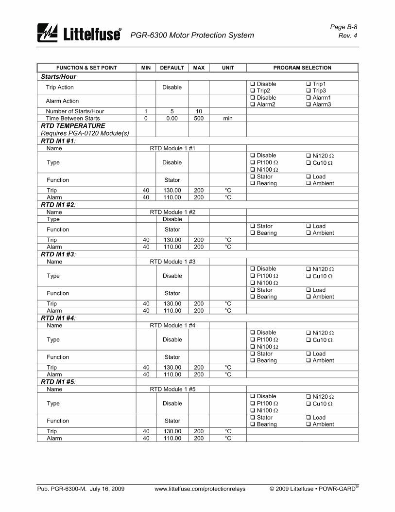
Page B-8 PGR-6300 Motor Protection System Rev. 4
Pub. PGR-6300-M. July 16, 2009 www.littelfuse.com/protectionrelays © 2009 Littelfuse • POWR-GARD®
FUNCTION & SET POINT MIN DEFAULT MAX UNIT PROGRAM SELECTION
Starts/Hour Trip Action Disable Disable
Trip2 Trip1 Trip3
Alarm Action Disable Alarm2
Alarm1 Alarm3
Number of Starts/Hour 1 5 10 Time Between Starts 0 0.00 500 min
RTD TEMPERATURE Requires PGA-0120 Module(s)
RTD M1 #1: Name RTD Module 1 #1
Type Disable Disable Pt100 Ω Ni100 Ω
Ni120 Ω Cu10 Ω
Function Stator Stator Bearing
Load Ambient
Trip 40 130.00 200 °C Alarm 40 110.00 200 °C
RTD M1 #2: Name RTD Module 1 #2 Type Disable
Function Stator Stator Bearing
Load Ambient
Trip 40 130.00 200 °C Alarm 40 110.00 200 °C
RTD M1 #3: Name RTD Module 1 #3
Type Disable Disable Pt100 Ω Ni100 Ω
Ni120 Ω Cu10 Ω
Function Stator Stator Bearing
Load Ambient
Trip 40 130.00 200 °C Alarm 40 110.00 200 °C
RTD M1 #4: Name RTD Module 1 #4
Type Disable Disable Pt100 Ω Ni100 Ω
Ni120 Ω Cu10 Ω
Function Stator Stator Bearing
Load Ambient
Trip 40 130.00 200 °C Alarm 40 110.00 200 °C
RTD M1 #5: Name RTD Module 1 #5
Type Disable Disable Pt100 Ω Ni100 Ω
Ni120 Ω Cu10 Ω
Function Stator Stator Bearing
Load Ambient
Trip 40 130.00 200 °C Alarm 40 110.00 200 °C

Page B-9 PGR-6300 Motor Protection System Rev. 4
Pub. PGR-6300-M. July 16, 2009 www.littelfuse.com/protectionrelays © 2009 Littelfuse • POWR-GARD®
FUNCTION & SET POINT MIN DEFAULT MAX UNIT PROGRAM SELECTION
RTD M1 #6: Name RTD Module 1 #6
Type Disable Disable Pt100 Ω Ni100 Ω
Ni120 Ω Cu10 Ω
Function Stator Stator Bearing
Load Ambient
Trip 40 130.00 200 °C Alarm 40 110.00 200 °C
RTD M1 #7: Name RTD Module 1 #7
Type Disable Disable Pt100 Ω Ni100 Ω
Ni120 Ω Cu10 Ω
Function Stator Stator Bearing
Load Ambient
Trip 40 130.00 200 °C Alarm 40 110.00 200 °C
RTD M1 #8: Name RTD Module 1 #8
Type Disable Disable Pt100 Ω Ni100 Ω
Ni120 Ω Cu10 Ω
Function Stator Stator Bearing
Load Ambient
Trip 40 130.00 200 °C Alarm 40 110.00 200 °C
RTD M2 #1: Name RTD Module 2 #1
Type Disable Disable Pt100 Ω Ni100 Ω
Ni120 Ω Cu10 Ω
Function Stator Stator Bearing
Load Ambient
Trip 40 130.00 200 °C Alarm 40 110.00 200 °C
RTD M2 #2: Name RTD Module 2 #2
Type Disable Disable Pt100 Ω Ni100 Ω
Ni120 Ω Cu10 Ω
Function Stator Stator Bearing
Load Ambient
Trip 40 130.00 200 °C Alarm 40 110.00 200 °C
RTD M2 #3: Name RTD Module 2 #3
Type Disable Disable Pt100 Ω Ni100 Ω
Ni120 Ω Cu10 Ω
Function Stator Stator Bearing
Load Ambient
Trip 40 130.00 200 °C Alarm 40 110.00 200 °C
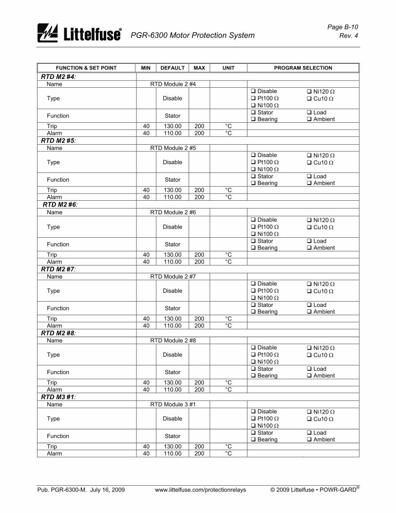
Page B-10 PGR-6300 Motor Protection System Rev. 4
Pub. PGR-6300-M. July 16, 2009 www.littelfuse.com/protectionrelays © 2009 Littelfuse • POWR-GARD®
FUNCTION & SET POINT MIN DEFAULT MAX UNIT PROGRAM SELECTION
RTD M2 #4: Name RTD Module 2 #4
Type Disable Disable Pt100 Ω Ni100 Ω
Ni120 Ω Cu10 Ω
Function Stator Stator Bearing
Load Ambient
Trip 40 130.00 200 °C Alarm 40 110.00 200 °C
RTD M2 #5: Name RTD Module 2 #5
Type Disable Disable Pt100 Ω Ni100 Ω
Ni120 Ω Cu10 Ω
Function Stator Stator Bearing
Load Ambient
Trip 40 130.00 200 °C Alarm 40 110.00 200 °C
RTD M2 #6: Name RTD Module 2 #6
Type Disable Disable Pt100 Ω Ni100 Ω
Ni120 Ω Cu10 Ω
Function Stator Stator Bearing
Load Ambient
Trip 40 130.00 200 °C Alarm 40 110.00 200 °C
RTD M2 #7: Name RTD Module 2 #7
Type Disable Disable Pt100 Ω Ni100 Ω
Ni120 Ω Cu10 Ω
Function Stator Stator Bearing
Load Ambient
Trip 40 130.00 200 °C Alarm 40 110.00 200 °C
RTD M2 #8: Name RTD Module 2 #8
Type Disable Disable Pt100 Ω Ni100 Ω
Ni120 Ω Cu10 Ω
Function Stator Stator Bearing
Load Ambient
Trip 40 130.00 200 °C Alarm 40 110.00 200 °C
RTD M3 #1: Name RTD Module 3 #1
Type Disable Disable Pt100 Ω Ni100 Ω
Ni120 Ω Cu10 Ω
Function Stator Stator Bearing
Load Ambient
Trip 40 130.00 200 °C Alarm 40 110.00 200 °C
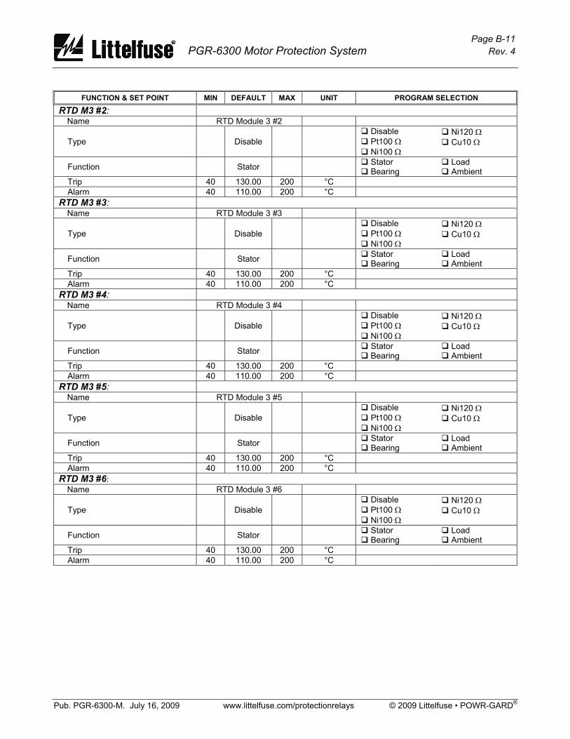
Page B-11 PGR-6300 Motor Protection System Rev. 4
Pub. PGR-6300-M. July 16, 2009 www.littelfuse.com/protectionrelays © 2009 Littelfuse • POWR-GARD®
FUNCTION & SET POINT MIN DEFAULT MAX UNIT PROGRAM SELECTION
RTD M3 #2: Name RTD Module 3 #2
Type Disable Disable Pt100 Ω Ni100 Ω
Ni120 Ω Cu10 Ω
Function Stator Stator Bearing
Load Ambient
Trip 40 130.00 200 °C Alarm 40 110.00 200 °C
RTD M3 #3: Name RTD Module 3 #3
Type Disable Disable Pt100 Ω Ni100 Ω
Ni120 Ω Cu10 Ω
Function Stator Stator Bearing
Load Ambient
Trip 40 130.00 200 °C Alarm 40 110.00 200 °C
RTD M3 #4: Name RTD Module 3 #4
Type Disable Disable Pt100 Ω Ni100 Ω
Ni120 Ω Cu10 Ω
Function Stator Stator Bearing
Load Ambient
Trip 40 130.00 200 °C Alarm 40 110.00 200 °C
RTD M3 #5: Name RTD Module 3 #5
Type Disable Disable Pt100 Ω Ni100 Ω
Ni120 Ω Cu10 Ω
Function Stator Stator Bearing
Load Ambient
Trip 40 130.00 200 °C Alarm 40 110.00 200 °C
RTD M3 #6: Name RTD Module 3 #6
Type Disable Disable Pt100 Ω Ni100 Ω
Ni120 Ω Cu10 Ω
Function Stator Stator Bearing
Load Ambient
Trip 40 130.00 200 °C Alarm 40 110.00 200 °C
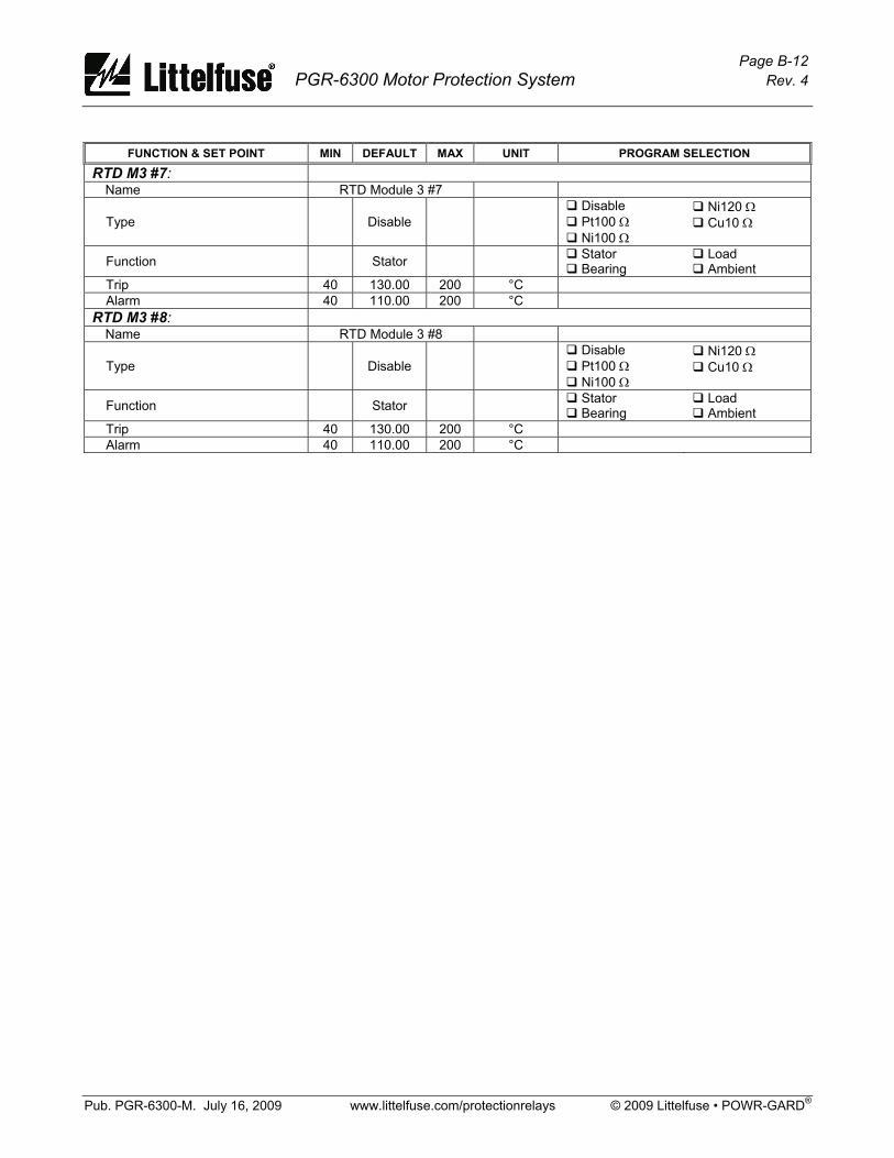
Page B-12 PGR-6300 Motor Protection System Rev. 4
Pub. PGR-6300-M. July 16, 2009 www.littelfuse.com/protectionrelays © 2009 Littelfuse • POWR-GARD®
FUNCTION & SET POINT MIN DEFAULT MAX UNIT PROGRAM SELECTION
RTD M3 #7: Name RTD Module 3 #7
Type Disable Disable Pt100 Ω Ni100 Ω
Ni120 Ω Cu10 Ω
Function Stator Stator Bearing
Load Ambient
Trip 40 130.00 200 °C Alarm 40 110.00 200 °C
RTD M3 #8: Name RTD Module 3 #8
Type Disable Disable Pt100 Ω Ni100 Ω
Ni120 Ω Cu10 Ω
Function Stator Stator Bearing
Load Ambient
Trip 40 130.00 200 °C Alarm 40 110.00 200 °C

Page C-1 PGR-6300 Motor Protection System Rev. 4
Pub. PGR-6300-M. July 16, 2009 www.littelfuse.com/protectionrelays © 2009 Littelfuse • POWR-GARD®
APPENDIX C PGR-6300 MODBUS PROTOCOL
C.1 PROTOCOL The PGR-6300 implements the Modbus® RTU protocol as described in the Gould Modbus Reference Guide, Publication PI-MBUS-300 Rev. B. The communications system consists of a single master and up to thirty-two PGR-6300 CTU slaves connected using a two-wire RS-485 network. If the master does not have an RS-485 port, an RS-232 to RS-485 converter is required. The converter must have automatic send-data control (SD). SD control does not require hand-shaking lines since it uses the data line to control the transmit/receive line on the RS-485 transceivers. Only the master can initiate a message transaction. Messages can be addressed to individual slaves or they can be broadcast messages. Broadcast messages are executed on the PGR-6300 slaves but unlike individually addressed messages, the slaves do not generate a reply message.
C.2 MESSAGE SYNCHRONIZATION Message synchronization is accomplished by detection of an idle communication line. The communication line is considered idle when no communication exists for an equivalent delay of 3.5 characters. The first byte received after idle-line detection is interpreted as the address byte of the next message. Message bytes must be transmitted in a continuous stream until the complete message has been sent. If a delay of more than 3.5 characters exists within the message, the message is discarded. Response messages from the PGR-6300 are delayed by at least 3.5 character delays.
C.3 ERROR CHECKING Modbus RTU uses a 16-bit cyclic redundancy check (CRC). The error check includes all of the message bytes, starting with the first address byte. When a CRC error is detected, the message is discarded and there will be no response. If the CRC check is correct but the internal data in the message is not correct, the PGR-6300 will respond with an exception response code. Modicon Modbus® is a registered trademark of Schneider Electric.
C.4 FUNCTION CODES SUPPORTED The PGR-6300 Modbus Protocol supports the following function codes: • Read Holding Registers (Function Code 3) • Read Input Registers (Function Code 4) • Write Single Register (Function Code 6) • Write Multiple Registers (Function Code 16) • Command Instruction (Function Code 5)
Function Codes 3 and 4 perform the same function in the PGR-6300. Registers in Modbus start at 40001 decimal and the register address generated for this register is 0. C4.1 Application Layer The hexadecimal system is used. Value representations use the “C” convention. For hexadecimal, 0x precedes the value. C.4.2 Read Input/Holding Registers (Code 04/03) The first byte of the read message is the slave address. The second byte is the function code. Bytes three and four indicate the starting register. The next two bytes specify the number of 16-bit registers to read. The last two bytes contain the CRC code for the message.
TABLE C.1 Read Registers (Code 04/03) HEX BYTE DESCRIPTION
Byte 1 Byte 2 Byte 3 Byte 4 Byte 5 Byte 6 Byte 7 Byte 8
Slave Address Function Code MSB Register Address LSB Register Address MSB Number of Registers LSB Number of Registers LSB CRC MSB CRC
The two-byte values of starting register and number of registers to read are transmitted with the high-order byte followed by the low-order byte. The CRC value is sent with the LSB followed by the MSB. The following message will obtain the value of register 1 (Modbus 40002) from slave 1. Note that Modbus registers are numbered from zero (40001 = zero, 40002 = one, etc.): 0x01 | 0x03 | 0x00 | 0x01 | 0x00 | 0x01 | 0xD5 | 0xCA The addressed slave responds with its address and Function Code 3, followed by the information field. The information field contains an 8-bit byte count and the 16-bit data from the slave. The byte count specifies the number of bytes of data in the information field. The data in the information field

Page C-2 PGR-6300 Motor Protection System Rev. 4
Pub. PGR-6300-M. July 16, 2009 www.littelfuse.com/protectionrelays © 2009 Littelfuse • POWR-GARD®
consists of 16-bit data arranged so that the MSB is followed by the LSB. The maximum number of 16-bit registers that can be read is 120. C.4.3 Write To Register Function Code 6 or 16 is used to make set-point changes. C.4.3.1 Write Single Register (Code 6) The function code format for writing a single register is shown in Table C.2. The message consists of the PGR-6300 address followed by the Function Code 6 and two 16-bit values. The first 16-bit value specifies the register to be modified and the second value is the 16-bit data. Provided no errors occurred, the slave will re-send the original message to the master. The response message is returned only after the command has been executed by the PGR-6300. The following message will set register 3 to 300 in slave 5: 0x05 | 0x06 | 0x00 | 0x03 | 0x01 | 0x2C | 0x78 | 0x03
TABLE C.2 Write Single Register (Code 6) HEX BYTE DESCRIPTION
Byte 1 Byte 2 Byte 3 Byte 4 Byte 5 Byte 6 Byte 7 Byte 8
Slave Address Function Code MSB Register Address LSB Register Address MSB of Data LSB of Data LSB of CRC MSB of CRC
C.4.3.2 Write Multiple Registers (Code 16) The function-code format in Table C.3 can be used for writing single or multiple registers.
TABLE C.3 Write Multiple Registers (Code 16) BYTE # DESCRIPTION Byte 1 Byte 2 Byte 3 Byte 4 Byte 5 Byte 6 Byte 7
.
.
. Byte n
Slave Address Function Code MSB Register Address LSB Register Address MSB of Quantity LSB of Quantity Byte Count MSB of Data LSB of Data LSB of CRC MSB of CRC
The PGR-6300 will reply with the slave address, function code, register address, and the quantity followed by the CRC code for a total of 8 bytes.
C.4.4 Command Instruction (Code 5) Modbus Function Code 5 (Force Single Coil) is used to issue commands to the PGR-6300. The format for the message is listed in Table C.4 and the command code actions and corresponding coil number are listed in Table C.5.
TABLE C.4 Command Format (Code 5) HEX BYTE DESCRIPTION
Byte 1 Byte 2 Byte 3 Byte 4 Byte 5 Byte 6 Byte 7 Byte 8
Slave Address Function Code MSB of Command Code LSB of Command Code Fixed at 0xff Fixed at 00 LSB of CRC MSB of CRC
TABLE C.5 Supported Commands
COMMAND CODE
COIL NUMBE
R
ACTION
0x0000 0x0001 0x0002 0x0003 0x0004 0x0005 0x0006 0x0007 0x0008 0x0009 0x000A 0x000B 0x000C
1 2 3 4 5 6 7 8 9
10 11 12 13
STOP START1 START2 Reset Trips Set Real-Time Clock Clear Data-Logging Records Clear Trip Counters Clear Energy Totals Clear Running Hours Emergency I2t and Trip Reset Select Local Control De-select Local Control Re-enable Temperature Protection
Except for a broadcast address, the slave will return the original packet to the master. C.4.5 Command Instructions Using Write Commands For PLC's not supporting Function Code 5, PGR-6300 commands can be issued using Write Single Register (Code 6) and Write Multiple Register (Code 16). Commands are written to PGR-6300 register 6 (Modbus register 40007). Supported commands are listed in the COMMAND CODE column in Table C.5. When using the Write Multiple Registers function code, the write should be to the single PGR-6300 Register 6. If multiple registers are written starting at PGR-6300 Register 6, the first data element will be interpreted as the command code but no other registers will be written. If the command is successful, the PGR-6300 will return a valid response message.

Page C-3 PGR-6300 Motor Protection System Rev. 4
Pub. PGR-6300-M. July 16, 2009 www.littelfuse.com/protectionrelays © 2009 Littelfuse • POWR-GARD®
C.4.6 Exception Responses The PGR-6300 supports the following exception responses: • Boundry Error (1)—Applies to writes of 32-bit
values. The high-order word must be written first followed by the write to the low-order word. If this sequence is not followed, a Boundry Error is returned and the value will not stored. This does not apply on read requests.
• Address Error (2)—All accesses to communication registers must be within the specified address range or the Address Error code is returned.
• Command Error (3)—This error code is returned if the command code is not supported.
• Illegal Function Code (4)—The function code (Byte 2) is not supported.
The exception message consists of the slave address followed by a retransmission of the original function code. The function code will have the most-significant bit set to indicate an error. The 8-bit byte following the function code is the exception response code. The 16-bit CRC is at the end of the message.
C.5 PGR-6300 DATABASE Appendix E contains the Modbus Register in the Communications Database Table. The table starts at register 0 (Modbus 40001) and each register is 16-bits wide. Types "long" and "float" are 32-bit values. For both long and float types, the low-order word is transmitted first followed by the high-order word. Word values have the high byte followed by the low byte. Float types as per IEEE 754 Floating-Point Standard. All bytes of long and float types must be written using one message or an error will result. This does not apply for read commands. C.5.1 Data Records Only one event record can be read at a time. Record data is for the record indicated by the Record Selector. To select a record, write the record number to Record Selector and then read the values in the record. Record Head points to the next available record. The last event record captured is at Record Head minus one. Both Record Selector and Record Head values are in the range of 0 to 63. Values outside this range will select record 0.
C.5.2 Custom Data Access Data access can be customized with the User-Defined Registers and the User-Data Registers. User-Defined Registers are located in non-volatile memory and contain the register numbers from which data is required. To access the data, read the corresponding User-Data Registers. The format of the User Data is a function of the corresponding register entered in the User-Defined-Register area.
C.6 NETWORK TIMEOUT The PGR-6300 can be configured to trip or alarm on a network timeout using the Setup | Hardware | Network Comms menu. The Net Trip Action and Net Alarm Action set points set the actions to be taken when a timeout occurs. To prevent a timeout, a valid message, addressed to the slave, must be received at time intervals less than five seconds. Caution: Set protocol to None before selecting Network Error actions; then, select protocol.
C.7 SPECIFICATIONS Interface ................................Isolated RS-485, 2 wire, multi-drop, half duplex. Protocol .................................Modbus RTU Baud Rate .............................1,200 to 19,200 bit/s. Bit Format..............................8 bits, no parity, one
stop bit(1) Number of CTU's Connected ..Maximum of 32 units. Bus length .............................1,200 m (4,000 ft) total(2) (1) Terminal “-” is negative with respect to terminal
“+” for a binary 1 (MARK or OFF) state. Terminal “-” is positive with respect to terminal “+”
for a binary 0 (SPACE or ON) state. (2) For line lengths exceeding 10 m (30 ft), 150-Ω
terminations are required at the cable ends.

Page C-4 PGR-6300 Motor Protection System Rev. 4
Pub. PGR-6300-M. July 16, 2009 www.littelfuse.com/protectionrelays © 2009 Littelfuse • POWR-GARD®
This page intentionally left blank.

Page D-1 PGR-6300 Motor Protection System Rev. 4
Pub. PGR-6300-M. July 16, 2009 www.littelfuse.com/protectionrelays © 2009 Littelfuse • POWR-GARD®
APPENDIX D PGR-6300 A-B DF1 PROTOCOL D.1 PROTOCOL The PGR-6300 A-B® Protocol is based on the half-duplex master/slave Allen-Bradley (A-B) Data Highway Protocol (DF1) as described in Allen-Bradley Bulletin 1770-6.5.16 October 1996. This publication is available from the A-B web site at www.ab.com. The communications system consists of a single master and up to thirty-two slaves connected to a two-wire RS-485 multi-drop network. PGR-6300 Control Units are slave devices on this network. If the master does not have an RS-485 port, an RS-232 to RS-485 converter is required. The RS-485 converter should have automatic send-data control (SD). SD control does not require handshaking lines since it uses the data line to control the RS-485 transmitter. The PGR-6300 supports the DF1 commands shown in Table D.1. Each PLC has limitations when using a particular command. Determine the best command to use for a particular application.
TABLE D.1 DF1 Commands COMMAND CMD FNC Unprotected Read 01 - Unprotected Write 08 - Typed Read 0F 68 Typed Write 0F 67 Typed Logical Read 0F A2 Typed Logical Write 0F AA The PLC-5 and SLC 500 support reading and writing to integer files (Type N) and float files (Type F). Since PGR-6300 meter values are float types, these will typically be stored in a PLC Type-F file. It is also possible to read float types from the PGR-6300 as two integers; however, further processing is required to obtain the float value. The PLC requires two communication ports—a PLC programming port and a PGR-6300 communications port. Typically, a DH+ port will be used for PLC programming and the RS-232 port is used for PGR-6300 communications via an RS-232 to RS-485 converter. A-B® is a registered trademark of Rockwell International Corporation.
D.2 PLC-5 / SLC 500 CHANNEL-0 SETUP The RS-232 Channel-0 port is set up for a DF1 half-duplex master. Set the Channel-0 baud rate and CRC to match the PGR-6300 settings. The parity bit is not supported on the PGR-6300. Where applicable, set Reply Message Wait to 100 ms. Additional recommended PLC settings: DF1 Retries = 3 RTS Send Delay = 1 (20 ms) RTS Off Delay = 0 Ack timeout = 5 (100 ms) Reply msg wait = 3 (60 ms) For the polling mode, select MESSAGE BASED (DO NOT ALLOW SLAVE TO INITIATE MESSAGES) or STANDARD (MULTIPLE MESSAGE-TRANSFER PER NODE SCAN). The PGR-6300 can buffer up to 3 messages. The selection MESSAGE BASED (DO NOT ALLOW SLAVE TO INITIATE MESSAGES) is recommended.
D.3 TYPED-READ The Typed-Read message is used to read data from the PGR-6300. The Typed-Read message requires a Control Block where the message configuration is stored. In the SLC, this is normally N7:0 but could be any other file that supports the control-block data. Use the following MSG settings: Read/Write: Read Target Device: PLC5 Local/Remote: Local Control Block: N7:0 Note: For the PLC-5, the message block must be of type MG so that the channel number can be set in the message setup screen. The Setup screen is used to specify file information. In the This Controller section, Data Table Address is the destination in the PLC where data is to be stored. This can be a float (Fx:x) file or an integer (Nx:x) file. Element Size must be set to the number of elements to transfer. This is a decimal value and this value is limited in some controllers. In the SLC 500, the maximum value for integers is 100 and for floats it is 50.

Page D-2 PGR-6300 Motor Protection System Rev. 4
Pub. PGR-6300-M. July 16, 2009 www.littelfuse.com/protectionrelays © 2009 Littelfuse • POWR-GARD®
In Target Device, set Data Table Address to the A-B File address listed in Appendix E. The A-B File in Appendix E is coded as FILE:ELEMENT. To read or write the element as floats, the PLC-5 address would be <F><FILE>:<ELEMENT> (Example F9:222). To read or write the element as integers, add 20 to the file number and preceed with N, <N><FILE+20>:<ELEMENT> (Example N29:222). Local Address is the PGR-6300 address. Example settings for reading 25 registers as float type (25 meter readings): Data Table Address: ..... F8:0 Element Size:................ 25 Target Device Data Table Address:.......... F6:0 Local Address: .............. 9 (Must match PGR-6300 setting) Note: To read float values, both data table addresses must be specified as float (F) type. Example settings for reading a block of 100 registers (16-bit integer): This could be a mix of float and integer values since floats can be transferred as two integers in the PGR-6300. Data Table Address: ..... N9:0 Element Size:................ 100 Target Device Data Table Address:.............. N23:264 (Start of Digital Inputs) Local Address: .............. 9 (Must match PGR-6300 setting) If a PGR-6300 float has been read into the PLC as two integers and stored in an N-type file, the float can be recovered by using two copy commands. Assume that the two integers from the PGR-6300 read command are stored in N9:0 and N9:1. The first copy command is used to swap the two words so they are in the correct order; copy N9:0 to N9:11, and copy N9:1 to N9:10. The second copy command will copy the two integers to the F-type file; copy N9:10 to F8:0 with a size of 1. The two integers are now combined correctly as a single 4-byte float located in F8:0.
D.4 TYPED-WRITE The Typed-Write message is used to write data to the PGR-6300. Read/Write: Write Target Device: PLC5 Local/Remote: Local Control Block: N7:0 The Setup screen is used to specify file information. In the This Controller section, Data Table Address is the source file in the SLC. This can be a float (Fx:x) file or an integer (Nx:x) file. Element Size must be set to the number of elements to transfer. For the PGR-6300, the maximum element size is 100 for integers and 50 for floats. In Target Device, set Data Table Address to the A-B File address listed in Appendix E. Both integer and float values sent from the SLC are in the correct byte order and interpreted correctly by the PGR-6300. The PGR-6300 will do a range check on all messages to ensure valid data. Local Address is the PGR-6300 address. Example settings for writing a single float to set the FLA Rating: Data-Table Address:......F8:0 (Location of FLA value) Element Size: ................1 Target-Device Data- Table Address: ..........F3:225 Local Address:...............9 (Must match PGR-6300 setting) Reset commands to the PGR-6300 are issued by writing an integer command code to PGR-6300 Register 6 (N23:6) A command message should only be issued when the command is required. Valid commands are shown Table D.2.
TABLE D.2 PGR-6300 Commands COMMAND CODE ACTION
0x0000 STOP 0x0001 START1 0x0002 START2 0x0003 Reset Trips 0x0004 Set Real-Time Clock 0x0005 Clear Data-Logging Records 0x0006 0x0007 0x0008 0x0009 0x000A 0x000B 0x000C
Clear Trip Counters Clear Energy Totals Clear Running Hours Emergency I2t and Trip Reset Select Local Control De-select Local Control Re-enable Temperature Protection
Page D-3 PGR-6300 Motor Protection System Rev. 4
Pub. PGR-6300-M. July 16, 2009 www.littelfuse.com/protectionrelays © 2009 Littelfuse • POWR-GARD®
Example settings for writing a PGR-6300 reset command: Data-Table Address:..... N9:0 (Reset code = 3) Element Size:................ 1 Target-Device Data- Table Address:.......... N23:6 (PGR-6300 Command Register location) Local Address: .............. 9 (Must match PGR-6300 setting) D.5 UNPROTECTED READ/WRITE For PLC-2 and PLC-3 processors not supporting Typed Read/Write messages, Unprotected Read/Write commands can be used. For these messages, the data address is the Octal value of the PGR-6300 Register in Appendix E. The size is the number of registers. The maximum number of registers that can be transferred in a single message is 100. Unprotected Read/Write commands are used by the PGW-COMM communication program. D.6 TYPED LOGICAL READ/WRITE The Typed Logical Read (CMD = 0F, FNC = A2) and Typed Logical Write (CMD = 0F, FNC = AA) messages are supported by the full line of SLC 500 processors and Prosoft MVIxx-DFCM communication interfaces. Both float (F) and integer (N) types are supported. Unlike the typed commands in Section D.3 and D.4 a file offset is not required for integer values. Use the A-B file address as listed in the PGR-6300 manual Appendix E and precede the address with F for float values and N for integer values. The maximum number of integers and floats that can be read is 100 and 50 respectively. Reset commands to the PGR-6300 are issued by writing one of the COMMAND CODES listed in Table D.2 to Register 6 (N3:6).
D.7 DATA RECORDS Only one event record can be read at a time. Data is for the record indicated by the Record Selector. To select a record, write the record number to Record Selector and then read the values in the record. Record-Head points to the next available record. The last event record captured is at Record Head minus one. Both Record-Selector and Record-Head values are in the range of 0 to 63. Values outside this range will select record 0.
D.8 CUSTOM DATA ACCESS Data access can be customized with the User-Defined Registers and the User Data Register. Enter the required data-register numbers in the User-Defined Registers. The format of user data is a function of the corresponding register. To access the data, read the corresponding User-Data Register.
D.9 NETWORK TIMEOUT The PGR-6300 can be configured to trip or alarm on a network timeout using the Setup | Hardware | Network Comms menu. The Net Trip Action and Net Alarm Action set points set the actions to be taken when a timeout occurs. To prevent a timeout, a valid message, addressed to the slave, must be received at time intervals less than five seconds. Caution: Set protocol to None before selecting Network Error actions; then, select protocol.
D.10 SPECIFICATIONS Interface................................... Isolated RS-485, 2 wire, multi-drop, half duplex. Protocol.................................... Modbus RTU Baud Rate................................ 1,200 to 19,200 bit/s. Bit Format ................................ 8 bits, no parity, one
stop bit (1) Number of CTU's Connected.. Maximum of 32 units. Bus length................................ 1,200 m (4,000 ft) total (2) (1) Terminal “-” is negative with respect to terminal “+”
for a binary 1 (MARK or OFF) state. Terminal “-” is positive with respect to terminal “+”
for a binary 0 (SPACE or ON) state. (2) For line lengths exceeding 10 m (30 ft), 150-Ω
terminations are required at the cable ends.

Page D-4 PGR-6300 Motor Protection System Rev. 4
Pub. PGR-6300-M. July 16, 2009 www.littelfuse.com/protectionrelays © 2009 Littelfuse • POWR-GARD®
This page intentionally left blank.
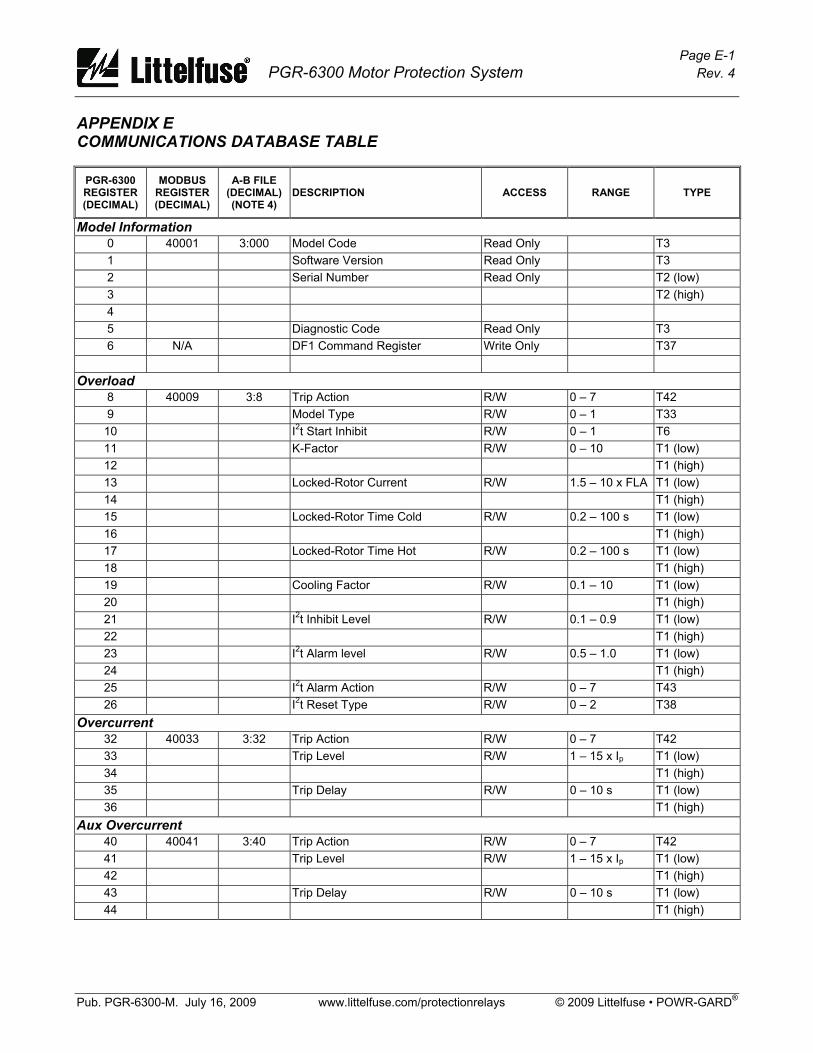
Page E-1 PGR-6300 Motor Protection System Rev. 4
Pub. PGR-6300-M. July 16, 2009 www.littelfuse.com/protectionrelays © 2009 Littelfuse • POWR-GARD®
APPENDIX E COMMUNICATIONS DATABASE TABLE
PGR-6300 REGISTER (DECIMAL)
MODBUS REGISTER (DECIMAL)
A-B FILE (DECIMAL) (NOTE 4)
DESCRIPTION ACCESS RANGE TYPE
Model Information 0 40001 3:000 Model Code Read Only T3 1 Software Version Read Only T3 2 Serial Number Read Only T2 (low) 3 T2 (high) 4 5 Diagnostic Code Read Only T3 6 N/A DF1 Command Register Write Only T37
Overload 8 40009 3:8 Trip Action R/W 0 – 7 T42 9 Model Type R/W 0 – 1 T33 10 I2t Start Inhibit R/W 0 – 1 T6 11 K-Factor R/W 0 – 10 T1 (low) 12 T1 (high) 13 Locked-Rotor Current R/W 1.5 – 10 x FLA T1 (low) 14 T1 (high) 15 Locked-Rotor Time Cold R/W 0.2 – 100 s T1 (low) 16 T1 (high) 17 Locked-Rotor Time Hot R/W 0.2 – 100 s T1 (low) 18 T1 (high) 19 Cooling Factor R/W 0.1 – 10 T1 (low) 20 T1 (high) 21 I2t Inhibit Level R/W 0.1 – 0.9 T1 (low) 22 T1 (high) 23 I2t Alarm level R/W 0.5 – 1.0 T1 (low) 24 T1 (high) 25 I2t Alarm Action R/W 0 – 7 T43 26 I2t Reset Type R/W 0 – 2 T38
Overcurrent 32 40033 3:32 Trip Action R/W 0 – 7 T42 33 Trip Level R/W 1 – 15 x Ip T1 (low) 34 T1 (high) 35 Trip Delay R/W 0 – 10 s T1 (low) 36 T1 (high)
Aux Overcurrent 40 40041 3:40 Trip Action R/W 0 – 7 T42 41 Trip Level R/W 1 – 15 x Ip T1 (low) 42 T1 (high) 43 Trip Delay R/W 0 – 10 s T1 (low) 44 T1 (high)

Page E-2 PGR-6300 Motor Protection System Rev. 4
Pub. PGR-6300-M. July 16, 2009 www.littelfuse.com/protectionrelays © 2009 Littelfuse • POWR-GARD®
PGR-6300 REGISTER (DECIMAL)
MODBUS REGISTER (DECIMAL)
A-B FILE (DECIMAL) (NOTE 4)
DESCRIPTION ACCESS RANGE TYPE
Reduced Overcurrent 45 40046 3:45 Trip Action R/W 0 – 7 T42 46 Trip Level R/W 1 – 15 x Ip T1 (low) 47 T1 (high)
Earth Fault 48 40049 3:48 Trip Action R/W 0 – 7 T42 49 Spare 50 Trip Level R/W 0.05 – 1.0 x Ie T1(low) 51 T1(high) 52 Trip Delay R/W 0 – 100 s T1(low) 53 T1(high) 54 Alarm Level R/W 0.05 – 1.0 x Ie T1(low) 55 T1(high) 56 Alarm Delay R/W 0 – 100 s T1(low) 57 T1(high) 58 Alarm Action R/W 0 – 7 T43
Jam 64 40065 3:64 Trip Action R/W 0 – 7 T42 65 Trip Level R/W 1 – 10 x FLA T1(low) 66 T1(high) 67 Trip Delay R/W 1 – 100 s T1(low) 68 T1(high) 69 Alarm Level R/W 1 – 10 x FLA T1(low) 70 T1(high) 71 Alarm Delay R/W 1 – 100 s T1(low) 72 T1(high) 73 Alarm Action R/W 0 – 7 T43
Current Unbalance 80 40081 3:80 Trip Action R/W 0 – 7 T42 81 Trip Level R/W 0.05 – 1.0 pu T1(low) 82 T1(high) 83 Trip Delay R/W 1.0 – 100 s T1(low) 84 T1(high) 85 Alarm Level R/W 0.05 – 1.0 pu T1(low) 86 T1(high) 87 Alarm Delay R/W 1.0 – 100 s T1(low) 88 T1(high) 89 Alarm Action R/W 0 – 7 T43
Phase Reverse (I) 95 40096 3:95 Alarm Action R/W 0 − 7 T43 96 Trip Action R/W 0 – 7 T42 97 Trip and Alarm Delay R/W 1 – 100 s T1(low) 98 T1(high)

Page E-3 PGR-6300 Motor Protection System Rev. 4
Pub. PGR-6300-M. July 16, 2009 www.littelfuse.com/protectionrelays © 2009 Littelfuse • POWR-GARD®
PGR-6300 REGISTER (DECIMAL)
MODBUS REGISTER (DECIMAL)
A-B FILE (DECIMAL) (NOTE 4)
DESCRIPTION ACCESS RANGE TYPE
Phase Loss (I) 99 40100 3:99 Trip Action R/W 0 – 7 T42
100 Trip Delay R/W 1 – 100 s T1(low) 101 T1(high)
Voltage Unbalance 104 40105 3:104 Trip Action R/W 0 – 7 T42 105 Trip Level R/W 0.05 – 1.0 pu T1(low) 106 T1(high) 107 Trip Delay R/W 1.0 – 100 T1(low) 108 T1(high) 109 Alarm Level R/W 0.05 – 1.0 pu T1(low) 110 T1(high) 111 Alarm Delay R/W 1.0 – 100 T1(low) 112 T1(high) 113 Alarm Action R/W 0 – 7 T43
Phase Reverse (V) 119 40120 3:119 Alarm Action R/W 0 − 7 T43 120 Trip Action R/W 0 – 7 T42 121 Trip and Alarm Delay R/W 1 – 100 s T1(low) 122 T1(high)
Phase Loss (V) 123 40124 3:123 Trip Action R/W 0 – 7 T42 124 Trip Delay R/W 1 – 100 s T1(low) 125 T1(high)
Undercurrent 128 40129 3:128 Trip Action R/W 0 – 7 T42 129 Trip Level R/W 0.1 – 1.0 x FLA T1(low) 130 T1(high) 131 Trip Delay R/W 1 – 100 s T1(low) 132 T1(high) 133 Alarm Level R/W 0.1 – 1.0 x FLA T1(low) 134 T1(high) 135 Alarm Delay R/W 1 – 100 s T1(low) 136 T1(high) 137 Alarm Action R/W 0 – 7 T43
PTC Temperature 144 40145 3:144 Trip Action R/W 0 – 7 T42 145 Alarm Action R/W 0 – 7 T43
Acceleration Failure—Underspeed 152 40153 3:152 Trip Action R/W 0 – 7 T42 153 Speed 1 R/W 1 – 100% FS T1(low) 154 T1(high) 155 Time 1 R/W 1 – 1,000 s T1(low) 156 T1(high)
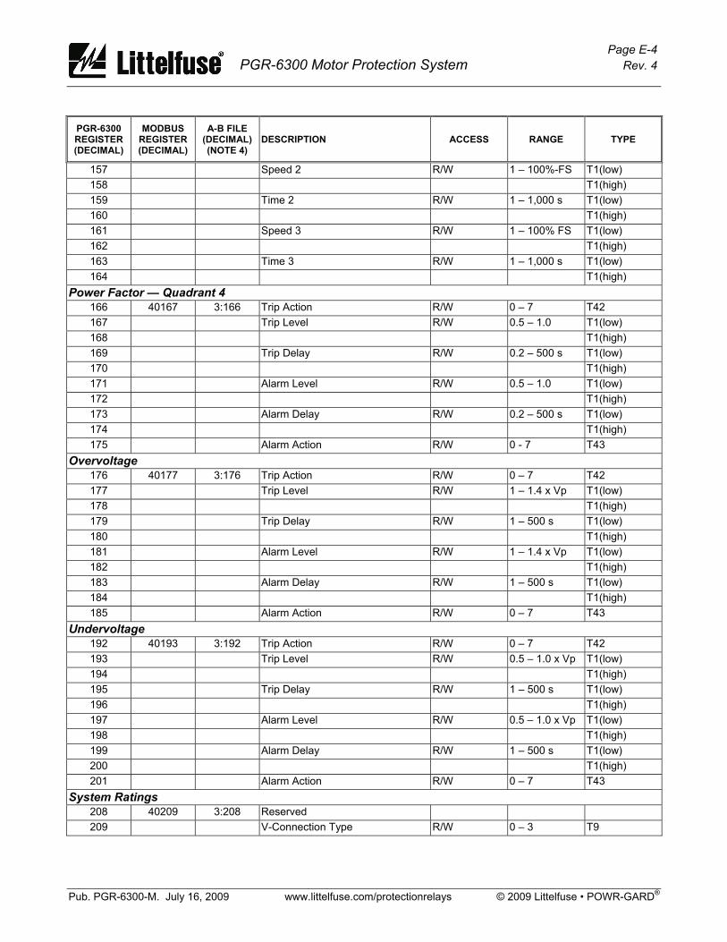
Page E-4 PGR-6300 Motor Protection System Rev. 4
Pub. PGR-6300-M. July 16, 2009 www.littelfuse.com/protectionrelays © 2009 Littelfuse • POWR-GARD®
PGR-6300 REGISTER (DECIMAL)
MODBUS REGISTER (DECIMAL)
A-B FILE (DECIMAL) (NOTE 4)
DESCRIPTION ACCESS RANGE TYPE
157 Speed 2 R/W 1 – 100%-FS T1(low) 158 T1(high) 159 Time 2 R/W 1 – 1,000 s T1(low) 160 T1(high) 161 Speed 3 R/W 1 – 100% FS T1(low) 162 T1(high) 163 Time 3 R/W 1 – 1,000 s T1(low) 164 T1(high)
Power Factor — Quadrant 4 166 40167 3:166 Trip Action R/W 0 – 7 T42 167 Trip Level R/W 0.5 – 1.0 T1(low) 168 T1(high) 169 Trip Delay R/W 0.2 – 500 s T1(low) 170 T1(high) 171 Alarm Level R/W 0.5 – 1.0 T1(low) 172 T1(high) 173 Alarm Delay R/W 0.2 – 500 s T1(low) 174 T1(high) 175 Alarm Action R/W 0 - 7 T43
Overvoltage 176 40177 3:176 Trip Action R/W 0 – 7 T42 177 Trip Level R/W 1 – 1.4 x Vp T1(low) 178 T1(high) 179 Trip Delay R/W 1 – 500 s T1(low) 180 T1(high) 181 Alarm Level R/W 1 – 1.4 x Vp T1(low) 182 T1(high) 183 Alarm Delay R/W 1 – 500 s T1(low) 184 T1(high) 185 Alarm Action R/W 0 – 7 T43
Undervoltage 192 40193 3:192 Trip Action R/W 0 – 7 T42 193 Trip Level R/W 0.5 – 1.0 x Vp T1(low) 194 T1(high) 195 Trip Delay R/W 1 – 500 s T1(low) 196 T1(high) 197 Alarm Level R/W 0.5 – 1.0 x Vp T1(low) 198 T1(high) 199 Alarm Delay R/W 1 – 500 s T1(low) 200 T1(high) 201 Alarm Action R/W 0 – 7 T43
System Ratings 208 40209 3:208 Reserved 209 V-Connection Type R/W 0 – 3 T9
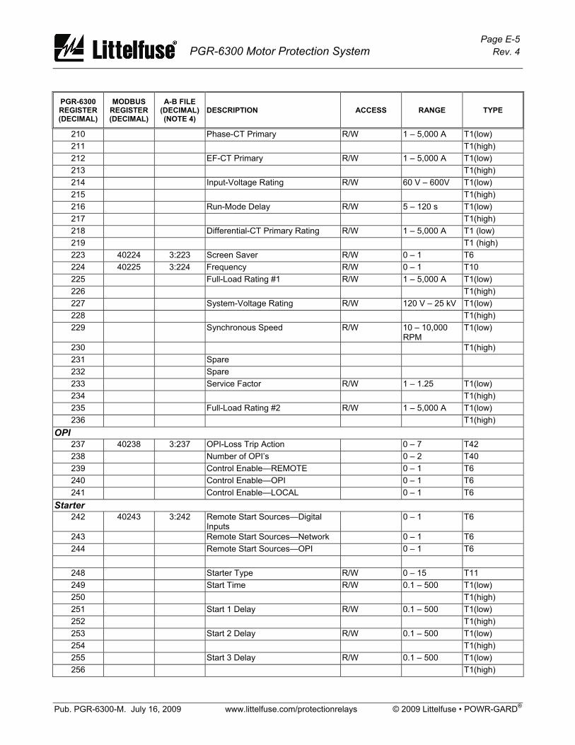
Page E-5 PGR-6300 Motor Protection System Rev. 4
Pub. PGR-6300-M. July 16, 2009 www.littelfuse.com/protectionrelays © 2009 Littelfuse • POWR-GARD®
PGR-6300 REGISTER (DECIMAL)
MODBUS REGISTER (DECIMAL)
A-B FILE (DECIMAL) (NOTE 4)
DESCRIPTION ACCESS RANGE TYPE
210 Phase-CT Primary R/W 1 – 5,000 A T1(low) 211 T1(high) 212 EF-CT Primary R/W 1 – 5,000 A T1(low) 213 T1(high) 214 Input-Voltage Rating R/W 60 V – 600V T1(low) 215 T1(high) 216 Run-Mode Delay R/W 5 – 120 s T1(low) 217 T1(high) 218 Differential-CT Primary Rating R/W 1 – 5,000 A T1 (low) 219 T1 (high) 223 40224 3:223 Screen Saver R/W 0 – 1 T6 224 40225 3:224 Frequency R/W 0 – 1 T10 225 Full-Load Rating #1 R/W 1 – 5,000 A T1(low) 226 T1(high) 227 System-Voltage Rating R/W 120 V – 25 kV T1(low) 228 T1(high) 229 Synchronous Speed R/W 10 – 10,000
RPM T1(low)
230 T1(high) 231 Spare 232 Spare 233 Service Factor R/W 1 – 1.25 T1(low) 234 T1(high) 235 Full-Load Rating #2 R/W 1 – 5,000 A T1(low) 236 T1(high)
OPI 237 40238 3:237 OPI-Loss Trip Action 0 – 7 T42 238 Number of OPI’s 0 – 2 T40 239 Control Enable—REMOTE 0 – 1 T6 240 Control Enable—OPI 0 – 1 T6 241 Control Enable—LOCAL 0 – 1 T6
Starter 242 40243 3:242 Remote Start Sources—Digital
Inputs 0 – 1 T6
243 Remote Start Sources—Network 0 – 1 T6 244 Remote Start Sources—OPI 0 – 1 T6
248 Starter Type R/W 0 – 15 T11 249 Start Time R/W 0.1 – 500 T1(low) 250 T1(high) 251 Start 1 Delay R/W 0.1 – 500 T1(low) 252 T1(high) 253 Start 2 Delay R/W 0.1 – 500 T1(low) 254 T1(high) 255 Start 3 Delay R/W 0.1 – 500 T1(low) 256 T1(high)
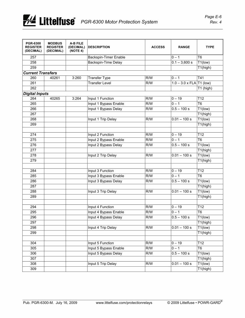
Page E-6 PGR-6300 Motor Protection System Rev. 4
Pub. PGR-6300-M. July 16, 2009 www.littelfuse.com/protectionrelays © 2009 Littelfuse • POWR-GARD®
PGR-6300 REGISTER (DECIMAL)
MODBUS REGISTER (DECIMAL)
A-B FILE (DECIMAL) (NOTE 4)
DESCRIPTION ACCESS RANGE TYPE
257 Backspin-Timer Enable 0 – 1 T6 258 Backspin-Time Delay 0.1 – 3,600 s T1(low) 259 T1(high)
Current Transfers 260 40261 3:260 Transfer Type R/W 0 – 1 T41 261 Transfer Level R/W 1.0 – 3.0 x FLA T1 (low) 262 T1 (high)
Digital Inputs 264 40265 3:264 Input 1 Function R/W 0 – 19 T12 265 Input 1 Bypass Enable R/W 0 – 1 T6 266 Input 1 Bypass Delay R/W 0.5 – 100 s T1(low) 267 T1(high) 268 Input 1 Trip Delay R/W 0.01 – 100 s T1(low) 269 T1(high)
274 Input 2 Function R/W 0 – 19 T12 275 Input 2 Bypass Enable R/W 0 – 1 T6 276 Input 2 Bypass Delay R/W 0.5 – 100 s T1(low) 277 T1(high) 278 Input 2 Trip Delay R/W 0.01 – 100 s T1(low) 279 T1(high)
284 Input 3 Function R/W 0 – 19 T12 285 Input 3 Bypass Enable R/W 0 – 1 T6 286 Input 3 Bypass Delay R/W 0.5 – 100 s T1(low) 287 T1(high) 288 Input 3 Trip Delay R/W 0.01 – 100 s T1(low) 289 T1(high)
294 Input 4 Function R/W 0 – 19 T12 295 Input 4 Bypass Enable R/W 0 – 1 T6 296 Input 4 Bypass Delay R/W 0.5 – 100 s T1(low) 297 T1(high) 298 Input 4 Trip Delay R/W 0.01 – 100 s T1(low) 299 T1(high)
304 Input 5 Function R/W 0 – 19 T12 305 Input 5 Bypass Enable R/W 0 – 1 T6 306 Input 5 Bypass Delay R/W 0.5 – 100 s T1(low) 307 T1(high) 308 Input 5 Trip Delay R/W 0.01 – 100 s T1(low) 309 T1(high)

Page E-7 PGR-6300 Motor Protection System Rev. 4
Pub. PGR-6300-M. July 16, 2009 www.littelfuse.com/protectionrelays © 2009 Littelfuse • POWR-GARD®
PGR-6300 REGISTER (DECIMAL)
MODBUS REGISTER (DECIMAL)
A-B FILE (DECIMAL) (NOTE 4)
DESCRIPTION ACCESS RANGE TYPE
314 Input 6 Function R/W 0 – 19 T12 315 Input 6 Bypass Enable R/W 0 – 1 T6 316 Input 6 Bypass Delay R/W 0.5 – 100 s T1(low) 317 T1(high) 318 Input 6 Trip Delay R/W 0.01 – 100 s T1(low) 319 T1(high)
324 Input 7 Function R/W 0 – 19 T12 325 Input 7 Bypass Enable R/W 0 – 1 T6 326 Input 7 Bypass Delay R/W 0.5 – 100 s T1(low) 327 T1(high) 328 Input 7 Delay R/W 0.01 – 100 s T1(low) 329 T1(high) 330 Digital Tachometer Enable R/W 0 – 1 T6 331 Pulses Per Revolution R/W 1 – 100 T1(low) 332 T1(high)
Relay Output Function 334 40335 3:334 Relay 1 Output Function R/W 0 – 20 T13 335 Relay 1 Mode R/W 0 – 1 T14 336 Relay 2 Output Function R/W 0 – 20 T13 337 Relay 2 Mode R/W 0 – 1 T14 338 Relay 3 Output Function R/W 0 – 20 T13 339 Relay 3 Mode R/W 0 – 1 T14 340 Relay 4 Output Function R/W 0 – 20 T13 341 Relay 4 Mode R/W 0 – 1 T14 342 Relay 5 Output Function R/W 0 – 20 T13 343 Relay 5 Mode R/W 0 – 1 T14 344 Relay Pulse Time R/W 0.05 – 10 s T1(low) 345 T1(high)
Analog Input 350 40351 3:350 Analog-Input Function R/W 0 – 3 T34 351 High-Level Trip R/W 0.1 – 20.0 mA T1(low) 352 T1(high) 353 Low-Level Trip R/W 0.1 – 20.0 mA T1(low) 354 T1(high) 355 Trip Delay R/W .01 – 100 s T1(low) 356 T1(high) 357 High-Level Alarm R/W 0.1 – 20.0 mA T1(low) 358 T1(high) 359 Low-Level Alarm R/W 0.1 – 20.0 mA T1(low) 360 T1(high) 361 Alarm Delay R/W .01 – 100 s T1(low) 362 T1(high)
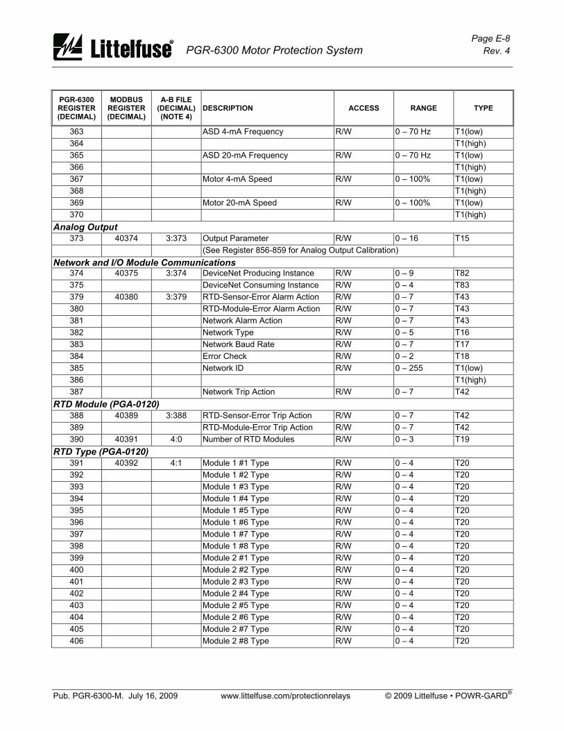
Page E-8 PGR-6300 Motor Protection System Rev. 4
Pub. PGR-6300-M. July 16, 2009 www.littelfuse.com/protectionrelays © 2009 Littelfuse • POWR-GARD®
PGR-6300 REGISTER (DECIMAL)
MODBUS REGISTER (DECIMAL)
A-B FILE (DECIMAL) (NOTE 4)
DESCRIPTION ACCESS RANGE TYPE
363 ASD 4-mA Frequency R/W 0 – 70 Hz T1(low) 364 T1(high) 365 ASD 20-mA Frequency R/W 0 – 70 Hz T1(low) 366 T1(high) 367 Motor 4-mA Speed R/W 0 – 100% T1(low) 368 T1(high) 369 Motor 20-mA Speed R/W 0 – 100% T1(low) 370 T1(high)
Analog Output 373 40374 3:373 Output Parameter R/W 0 – 16 T15
(See Register 856-859 for Analog Output Calibration) Network and I/O Module Communications
374 40375 3:374 DeviceNet Producing Instance R/W 0 – 9 T82 375 DeviceNet Consuming Instance R/W 0 – 4 T83 379 40380 3:379 RTD-Sensor-Error Alarm Action R/W 0 – 7 T43 380 RTD-Module-Error Alarm Action R/W 0 – 7 T43 381 Network Alarm Action R/W 0 – 7 T43 382 Network Type R/W 0 – 5 T16 383 Network Baud Rate R/W 0 – 7 T17 384 Error Check R/W 0 – 2 T18 385 Network ID R/W 0 – 255 T1(low) 386 T1(high) 387 Network Trip Action R/W 0 – 7 T42
RTD Module (PGA-0120) 388 40389 3:388 RTD-Sensor-Error Trip Action R/W 0 – 7 T42 389 RTD-Module-Error Trip Action R/W 0 – 7 T42 390 40391 4:0 Number of RTD Modules R/W 0 – 3 T19
RTD Type (PGA-0120) 391 40392 4:1 Module 1 #1 Type R/W 0 – 4 T20 392 Module 1 #2 Type R/W 0 – 4 T20 393 Module 1 #3 Type R/W 0 – 4 T20 394 Module 1 #4 Type R/W 0 – 4 T20 395 Module 1 #5 Type R/W 0 – 4 T20 396 Module 1 #6 Type R/W 0 – 4 T20 397 Module 1 #7 Type R/W 0 – 4 T20 398 Module 1 #8 Type R/W 0 – 4 T20 399 Module 2 #1 Type R/W 0 – 4 T20 400 Module 2 #2 Type R/W 0 – 4 T20 401 Module 2 #3 Type R/W 0 – 4 T20 402 Module 2 #4 Type R/W 0 – 4 T20 403 Module 2 #5 Type R/W 0 – 4 T20 404 Module 2 #6 Type R/W 0 – 4 T20 405 Module 2 #7 Type R/W 0 – 4 T20 406 Module 2 #8 Type R/W 0 – 4 T20
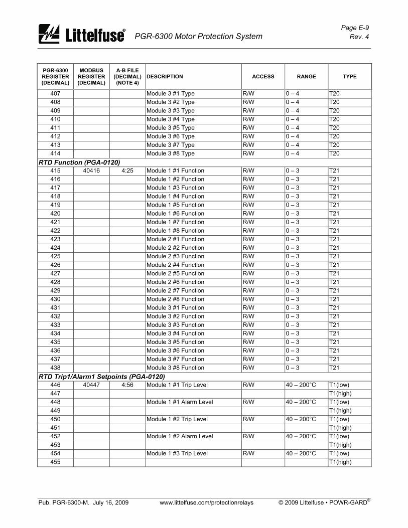
Page E-9 PGR-6300 Motor Protection System Rev. 4
Pub. PGR-6300-M. July 16, 2009 www.littelfuse.com/protectionrelays © 2009 Littelfuse • POWR-GARD®
PGR-6300 REGISTER (DECIMAL)
MODBUS REGISTER (DECIMAL)
A-B FILE (DECIMAL) (NOTE 4)
DESCRIPTION ACCESS RANGE TYPE
407 Module 3 #1 Type R/W 0 – 4 T20 408 Module 3 #2 Type R/W 0 – 4 T20 409 Module 3 #3 Type R/W 0 – 4 T20 410 Module 3 #4 Type R/W 0 – 4 T20 411 Module 3 #5 Type R/W 0 – 4 T20 412 Module 3 #6 Type R/W 0 – 4 T20 413 Module 3 #7 Type R/W 0 – 4 T20 414 Module 3 #8 Type R/W 0 – 4 T20
RTD Function (PGA-0120) 415 40416 4:25 Module 1 #1 Function R/W 0 – 3 T21 416 Module 1 #2 Function R/W 0 – 3 T21 417 Module 1 #3 Function R/W 0 – 3 T21 418 Module 1 #4 Function R/W 0 – 3 T21 419 Module 1 #5 Function R/W 0 – 3 T21 420 Module 1 #6 Function R/W 0 – 3 T21 421 Module 1 #7 Function R/W 0 – 3 T21 422 Module 1 #8 Function R/W 0 – 3 T21 423 Module 2 #1 Function R/W 0 – 3 T21 424 Module 2 #2 Function R/W 0 – 3 T21 425 Module 2 #3 Function R/W 0 – 3 T21 426 Module 2 #4 Function R/W 0 – 3 T21 427 Module 2 #5 Function R/W 0 – 3 T21 428 Module 2 #6 Function R/W 0 – 3 T21 429 Module 2 #7 Function R/W 0 – 3 T21 430 Module 2 #8 Function R/W 0 – 3 T21 431 Module 3 #1 Function R/W 0 – 3 T21 432 Module 3 #2 Function R/W 0 – 3 T21 433 Module 3 #3 Function R/W 0 – 3 T21 434 Module 3 #4 Function R/W 0 – 3 T21 435 Module 3 #5 Function R/W 0 – 3 T21 436 Module 3 #6 Function R/W 0 – 3 T21 437 Module 3 #7 Function R/W 0 – 3 T21 438 Module 3 #8 Function R/W 0 – 3 T21
RTD Trip1/Alarm1 Setpoints (PGA-0120) 446 40447 4:56 Module 1 #1 Trip Level R/W 40 – 200°C T1(low) 447 T1(high) 448 Module 1 #1 Alarm Level R/W 40 – 200°C T1(low) 449 T1(high) 450 Module 1 #2 Trip Level R/W 40 – 200°C T1(low) 451 T1(high) 452 Module 1 #2 Alarm Level R/W 40 – 200°C T1(low) 453 T1(high) 454 Module 1 #3 Trip Level R/W 40 – 200°C T1(low) 455 T1(high)

Page E-10 PGR-6300 Motor Protection System Rev. 4
Pub. PGR-6300-M. July 16, 2009 www.littelfuse.com/protectionrelays © 2009 Littelfuse • POWR-GARD®
PGR-6300 REGISTER (DECIMAL)
MODBUS REGISTER (DECIMAL)
A-B FILE (DECIMAL) (NOTE 4)
DESCRIPTION ACCESS RANGE TYPE
456 Module 1 #3 Alarm Level R/W 40 – 200°C T1(low) 457 T1(high) 458 Module 1 #4 Trip Level R/W 40 – 200°C T1(low) 459 T1(high) 460 Module 1 #4 Alarm Level R/W 40 – 200°C T1(low) 461 T1(high) 462 Module 1 #5 Trip Level R/W 40 – 200°C T1(low) 463 T1(high) 464 Module 1 #5 Alarm Level R/W 40 – 200°C T1(low) 465 T1(high) 466 Module 1 #6 Trip Level R/W 40 – 200°C T1(low) 467 T1(high) 468 Module 1 #6 Alarm Level R/W 40 – 200°C T1(low) 469 T1(high) 470 Module 1 #7 Trip Level R/W 40 – 200°C T1(low) 471 T1(high) 472 Module 1 #7 Alarm Level R/W 40 – 200°C T1(low) 473 T1(high) 474 Module 1 #8 Trip Level R/W 40 – 200°C T1(low) 475 T1(high) 476 Module 1 #8 Alarm Level R/W 40 – 200°C T1(low) 477 T1(high) 478 Module 2 #1 Trip Level R/W 40 – 200°C T1(low) 479 T1(high) 480 Module 2 #1 Alarm Level R/W 40 – 200°C T1(low) 481 T1(high) 482 Module 2 #2 Trip Level R/W 40 – 200°C T1(low) 483 T1(high) 484 Module 2 #2 Alarm Level R/W 40 – 200°C T1(low) 485 T1(high) 486 Module 2 #3 Trip Level R/W 40 – 200°C T1(low) 487 T1(high) 488 Module 2 #3 Alarm Level R/W 40 – 200°C T1(low) 489 T1(high) 490 Module 2 #4 Trip Level R/W 40 – 200°C T1(low) 491 T1(high) 492 Module 2 #4 Alarm Level R/W 40 – 200°C T1(low) 493 T1(high) 494 Module 2 #5 Trip Level R/W 40 – 200°C T1(low) 495 T1(high) 496 Module 2 #5 Alarm Level R/W 40 – 200°C T1(low) 497 T1(high) 498 Module 2 #6 Trip Level R/W 40 – 200°C T1(low) 499 T1(high)
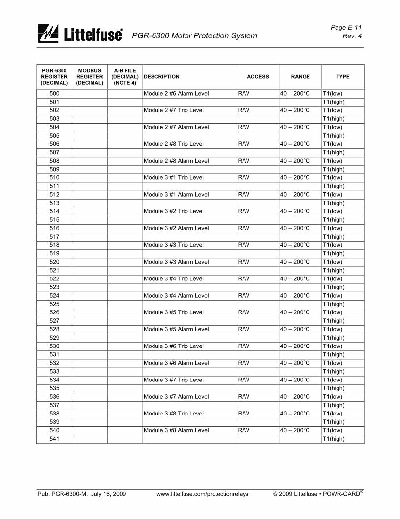
Page E-11 PGR-6300 Motor Protection System Rev. 4
Pub. PGR-6300-M. July 16, 2009 www.littelfuse.com/protectionrelays © 2009 Littelfuse • POWR-GARD®
PGR-6300 REGISTER (DECIMAL)
MODBUS REGISTER (DECIMAL)
A-B FILE (DECIMAL) (NOTE 4)
DESCRIPTION ACCESS RANGE TYPE
500 Module 2 #6 Alarm Level R/W 40 – 200°C T1(low) 501 T1(high) 502 Module 2 #7 Trip Level R/W 40 – 200°C T1(low) 503 T1(high) 504 Module 2 #7 Alarm Level R/W 40 – 200°C T1(low) 505 T1(high) 506 Module 2 #8 Trip Level R/W 40 – 200°C T1(low) 507 T1(high) 508 Module 2 #8 Alarm Level R/W 40 – 200°C T1(low) 509 T1(high) 510 Module 3 #1 Trip Level R/W 40 – 200°C T1(low) 511 T1(high) 512 Module 3 #1 Alarm Level R/W 40 – 200°C T1(low) 513 T1(high) 514 Module 3 #2 Trip Level R/W 40 – 200°C T1(low) 515 T1(high) 516 Module 3 #2 Alarm Level R/W 40 – 200°C T1(low) 517 T1(high) 518 Module 3 #3 Trip Level R/W 40 – 200°C T1(low) 519 T1(high) 520 Module 3 #3 Alarm Level R/W 40 – 200°C T1(low) 521 T1(high) 522 Module 3 #4 Trip Level R/W 40 – 200°C T1(low) 523 T1(high) 524 Module 3 #4 Alarm Level R/W 40 – 200°C T1(low) 525 T1(high) 526 Module 3 #5 Trip Level R/W 40 – 200°C T1(low) 527 T1(high) 528 Module 3 #5 Alarm Level R/W 40 – 200°C T1(low) 529 T1(high) 530 Module 3 #6 Trip Level R/W 40 – 200°C T1(low) 531 T1(high) 532 Module 3 #6 Alarm Level R/W 40 – 200°C T1(low) 533 T1(high) 534 Module 3 #7 Trip Level R/W 40 – 200°C T1(low) 535 T1(high) 536 Module 3 #7 Alarm Level R/W 40 – 200°C T1(low) 537 T1(high) 538 Module 3 #8 Trip Level R/W 40 – 200°C T1(low) 539 T1(high) 540 Module 3 #8 Alarm Level R/W 40 – 200°C T1(low) 541 T1(high)
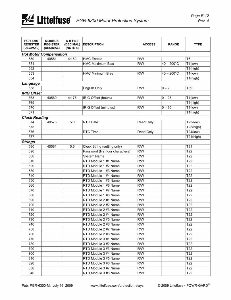
Page E-12 PGR-6300 Motor Protection System Rev. 4
Pub. PGR-6300-M. July 16, 2009 www.littelfuse.com/protectionrelays © 2009 Littelfuse • POWR-GARD®
PGR-6300 REGISTER (DECIMAL)
MODBUS REGISTER (DECIMAL)
A-B FILE (DECIMAL) (NOTE 4)
DESCRIPTION ACCESS RANGE TYPE
Hot Motor Compensation 550 40551 4:160 HMC Enable R/W T6 551 HMC Maximum Bias R/W 40 – 200°C T1(low) 552 T1(high) 553 HMC Minimum Bias R/W 40 – 200°C T1(low) 554 T1(high)
Language 558 English Only R/W 0 – 2 T39
IRIG Offset 568 40569 4:178 IRIG Offset (hours) R/W 0 – 23 T1(low) 569 T1(high) 570 IRIG Offset (minutes) R/W 0 – 30 T1(low) 571 T1(high)
Clock Reading 574 40575 5:0 RTC Date Read Only T23(low) 575 T23(high) 576 RTC Time Read Only T24(low) 577 T24(high)
Strings 580 40581 5:6 Clock String (setting only) R/W T31 590 Password (first four characters) R/W T22 600 System Name R/W T22 610 RTD Module 1 #1 Name R/W T22 620 RTD Module 1 #2 Name R/W T22 630 RTD Module 1 #3 Name R/W T22 640 RTD Module 1 #4 Name R/W T22 650 RTD Module 1 #5 Name R/W T22 660 RTD Module 1 #6 Name R/W T22 670 RTD Module 1 #7 Name R/W T22 680 RTD Module 1 #8 Name R/W T22 690 RTD Module 2 #1 Name R/W T22 700 RTD Module 2 #2 Name R/W T22 710 RTD Module 2 #3 Name R/W T22 720 RTD Module 2 #4 Name R/W T22 730 RTD Module 2 #5 Name R/W T22 740 RTD Module 2 #6 Name R/W T22 750 RTD Module 2 #7 Name R/W T22 760 RTD Module 2 #8 Name R/W T22 770 RTD Module 3 #1 Name R/W T22 780 RTD Module 3 #2 Name R/W T22 790 RTD Module 3 #3 Name R/W T22 800 RTD Module 3 #4 Name R/W T22 810 RTD Module 3 #5 Name R/W T22 820 RTD Module 3 #6 Name R/W T22 830 RTD Module 3 #7 Name R/W T22 840 RTD Module 3 #8 Name R/W T22

Page E-13 PGR-6300 Motor Protection System Rev. 4
Pub. PGR-6300-M. July 16, 2009 www.littelfuse.com/protectionrelays © 2009 Littelfuse • POWR-GARD®
PGR-6300 REGISTER (DECIMAL)
MODBUS REGISTER (DECIMAL)
A-B FILE (DECIMAL) (NOTE 4)
DESCRIPTION ACCESS RANGE TYPE
Analog Output Calibration 856 40857 5:282 Analog-Output Calibration (zero) R/W 0 – 1,000 T1(low) 857 T1(high) 858 Analog-Output Calibration (FS) R/W 0 – 1,000 T1(low) 859 T1(high)
Meter Values 860 40861 6:0 Ia (A) Read Only T1(low) 861 T1(high) 862 Ib (A) Read Only T1(low) 863 T1(high) 864 Ic (A) Read Only T1(low) 865 T1(high) 866 Ig (A) Read Only T1(low) 867 T1(high) 868 Vab (kV) Read Only T1(low) 869 T1(high) 870 Vbc (kV) Read Only T1(low) 871 T1(high) 872 Vca (kV) Read Only T1(low) 873 T1(high) 874 Apparent Power (S) in kVA Read Only T1(low) 875 T1(high) 876 Reactive Power (Q) in kVAR Read Only T1(low) 877 T1(high) 878 Real Power (P) in kW Read Only T1(low) 879 T1(high) 880 Power Factor (-1 to +1) Read Only T1(low) 881 T1(high) 882 Used Thermal Capacity (%) Read Only T1(low) 883 T1(high) 884 Analog Input (mA) Read Only T1(low) 885 T1(high) 886 Trend I2t (%) Read Only T1(low) 887 T1(high) 888 Positive-Sequence Current (pu) Read Only T1(low) 889 T1(high) 890 Negative-Sequence Current (pu) Read Only T1(low) 891 T1(high) 892 Unbalance (I) (pu) Read Only T1(low) 893 T1(high) 894 Positive-Sequence V (pu) Read Only T1(low) 895 T1(high) 896 Negative-Sequence V (pu) Read Only T1(low) 897 T1(high)
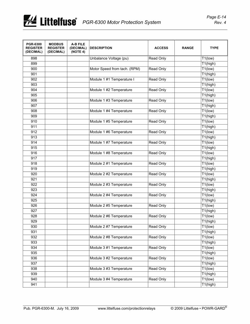
Page E-14 PGR-6300 Motor Protection System Rev. 4
Pub. PGR-6300-M. July 16, 2009 www.littelfuse.com/protectionrelays © 2009 Littelfuse • POWR-GARD®
PGR-6300 REGISTER (DECIMAL)
MODBUS REGISTER (DECIMAL)
A-B FILE (DECIMAL) (NOTE 4)
DESCRIPTION ACCESS RANGE TYPE
898 Unbalance Voltage (pu) Read Only T1(low) 899 T1(high) 900 Motor Speed from tach. (RPM) Read Only T1(low) 901 T1(high) 902 Module 1 #1 Temperature I Read Only T1(low) 903 T1(high) 904 Module 1 #2 Temperature Read Only T1(low) 905 T1(high) 906 Module 1 #3 Temperature Read Only T1(low) 907 T1(high) 908 Module 1 #4 Temperature Read Only T1(low) 909 T1(high) 910 Module 1 #5 Temperature Read Only T1(low) 911 T1(high) 912 Module 1 #6 Temperature Read Only T1(low) 913 T1(high) 914 Module 1 #7 Temperature Read Only T1(low) 915 T1(high) 916 Module 1 #8 Temperature Read Only T1(low) 917 T1(high) 918 Module 2 #1 Temperature Read Only T1(low) 919 T1(high) 920 Module 2 #2 Temperature Read Only T1(low) 921 T1(high) 922 Module 2 #3 Temperature Read Only T1(low) 923 T1(high) 924 Module 2 #4 Temperature Read Only T1(low) 925 T1(high) 926 Module 2 #5 Temperature Read Only T1(low) 927 T1(high) 928 Module 2 #6 Temperature Read Only T1(low) 929 T1(high) 930 Module 2 #7 Temperature Read Only T1(low) 931 T1(high) 932 Module 2 #8 Temperature Read Only T1(low) 933 T1(high) 934 Module 3 #1 Temperature Read Only T1(low) 935 T1(high) 936 Module 3 #2 Temperature Read Only T1(low) 937 T1(high) 938 Module 3 #3 Temperature Read Only T1(low) 939 T1(high) 940 Module 3 #4 Temperature Read Only T1(low) 941 T1(high)
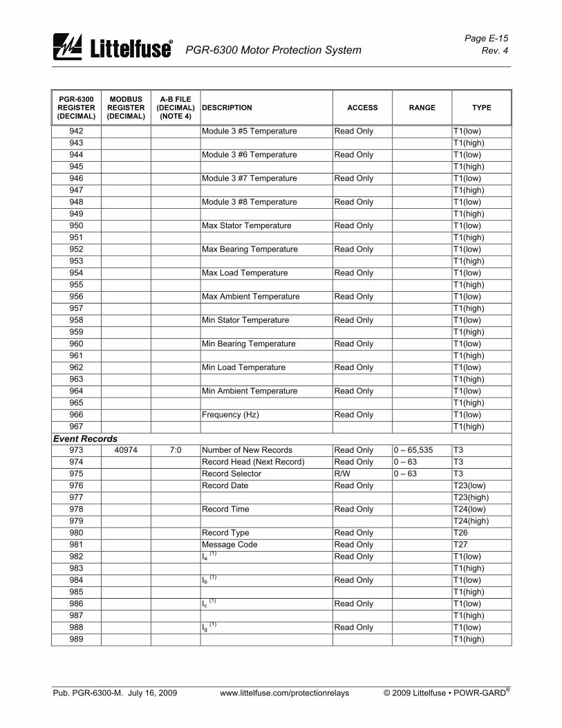
Page E-15 PGR-6300 Motor Protection System Rev. 4
Pub. PGR-6300-M. July 16, 2009 www.littelfuse.com/protectionrelays © 2009 Littelfuse • POWR-GARD®
PGR-6300 REGISTER (DECIMAL)
MODBUS REGISTER (DECIMAL)
A-B FILE (DECIMAL) (NOTE 4)
DESCRIPTION ACCESS RANGE TYPE
942 Module 3 #5 Temperature Read Only T1(low) 943 T1(high) 944 Module 3 #6 Temperature Read Only T1(low) 945 T1(high) 946 Module 3 #7 Temperature Read Only T1(low) 947 T1(high) 948 Module 3 #8 Temperature Read Only T1(low) 949 T1(high) 950 Max Stator Temperature Read Only T1(low) 951 T1(high) 952 Max Bearing Temperature Read Only T1(low) 953 T1(high) 954 Max Load Temperature Read Only T1(low) 955 T1(high) 956 Max Ambient Temperature Read Only T1(low) 957 T1(high) 958 Min Stator Temperature Read Only T1(low) 959 T1(high) 960 Min Bearing Temperature Read Only T1(low) 961 T1(high) 962 Min Load Temperature Read Only T1(low) 963 T1(high) 964 Min Ambient Temperature Read Only T1(low) 965 T1(high) 966 Frequency (Hz) Read Only T1(low) 967 T1(high)
Event Records 973 40974 7:0 Number of New Records Read Only 0 – 65,535 T3 974 Record Head (Next Record) Read Only 0 – 63 T3 975 Record Selector R/W 0 – 63 T3 976 Record Date Read Only T23(low) 977 T23(high) 978 Record Time Read Only T24(low) 979 T24(high) 980 Record Type Read Only T26 981 Message Code Read Only T27 982 Ia (1) Read Only T1(low) 983 T1(high) 984 Ib (1) Read Only T1(low) 985 T1(high) 986 Ic (1) Read Only T1(low) 987 T1(high) 988 Ig (1) Read Only T1(low) 989 T1(high)
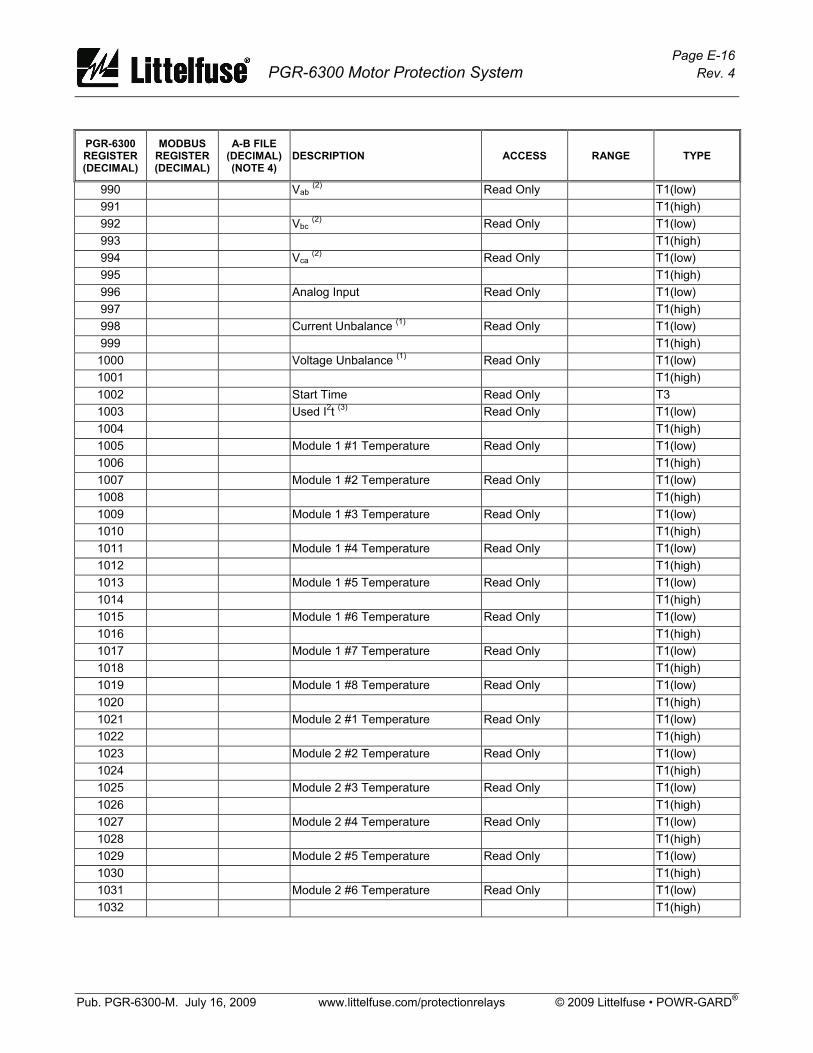
Page E-16 PGR-6300 Motor Protection System Rev. 4
Pub. PGR-6300-M. July 16, 2009 www.littelfuse.com/protectionrelays © 2009 Littelfuse • POWR-GARD®
PGR-6300 REGISTER (DECIMAL)
MODBUS REGISTER (DECIMAL)
A-B FILE (DECIMAL) (NOTE 4)
DESCRIPTION ACCESS RANGE TYPE
990 Vab (2) Read Only T1(low) 991 T1(high) 992 Vbc (2) Read Only T1(low) 993 T1(high) 994 Vca (2) Read Only T1(low) 995 T1(high) 996 Analog Input Read Only T1(low) 997 T1(high) 998 Current Unbalance (1) Read Only T1(low) 999 T1(high)
1000 Voltage Unbalance (1) Read Only T1(low) 1001 T1(high) 1002 Start Time Read Only T3 1003 Used I2t (3) Read Only T1(low) 1004 T1(high) 1005 Module 1 #1 Temperature Read Only T1(low) 1006 T1(high) 1007 Module 1 #2 Temperature Read Only T1(low) 1008 T1(high) 1009 Module 1 #3 Temperature Read Only T1(low) 1010 T1(high) 1011 Module 1 #4 Temperature Read Only T1(low) 1012 T1(high) 1013 Module 1 #5 Temperature Read Only T1(low) 1014 T1(high) 1015 Module 1 #6 Temperature Read Only T1(low) 1016 T1(high) 1017 Module 1 #7 Temperature Read Only T1(low) 1018 T1(high) 1019 Module 1 #8 Temperature Read Only T1(low) 1020 T1(high) 1021 Module 2 #1 Temperature Read Only T1(low) 1022 T1(high) 1023 Module 2 #2 Temperature Read Only T1(low) 1024 T1(high) 1025 Module 2 #3 Temperature Read Only T1(low) 1026 T1(high) 1027 Module 2 #4 Temperature Read Only T1(low) 1028 T1(high) 1029 Module 2 #5 Temperature Read Only T1(low) 1030 T1(high) 1031 Module 2 #6 Temperature Read Only T1(low) 1032 T1(high)
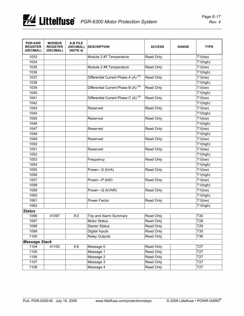
Page E-17 PGR-6300 Motor Protection System Rev. 4
Pub. PGR-6300-M. July 16, 2009 www.littelfuse.com/protectionrelays © 2009 Littelfuse • POWR-GARD®
PGR-6300 REGISTER (DECIMAL)
MODBUS REGISTER (DECIMAL)
A-B FILE (DECIMAL) (NOTE 4)
DESCRIPTION ACCESS RANGE TYPE
1033 Module 2 #7 Temperature Read Only T1(low) 1034 T1(high) 1035 Module 2 #8 Temperature Read Only T1(low) 1036 T1(high) 1037 Differential Current Phase A (A) (6) Read Only T1(low) 1038 T1(high) 1039 Differential Current Phase B (A) (6) Read Only T1(low) 1040 T1(high) 1041 Differential Current Phase C (A) (6) Read Only T1(low) 1042 T1(high) 1043 Reserved Read Only T1(low) 1044 T1(high) 1045 Reserved Read Only T1(low) 1046 T1(high) 1047 Reserved Read Only T1(low) 1048 T1(high) 1049 Reserved Read Only T1(low) 1050 T1(high) 1051 Reserved Read Only T1(low) 1052 T1(high) 1053 Frequency Read Only T1(low) 1054 T1(high) 1055 Power—S (kVA) Read Only T1(low) 1056 T1(high) 1057 Power—P (kW) Read Only T1(low) 1058 T1(high) 1059 Power—Q (kVAR) Read Only T1(low) 1060 T1(high) 1061 Power Factor Read Only T1(low) 1062 T1(high)
Status 1096 41097 8:0 Trip and Alarm Summary Read Only T30 1097 Motor Status Read Only T28 1098 Starter Status Read Only T29 1099 Digital Inputs Read Only T35 1100 Relay Outputs Read Only T36
Message Stack 1104 41105 8:8 Message 0 Read Only T27 1105 Message 1 Read Only T27 1106 Message 2 Read Only T27 1107 Message 3 Read Only T27 1108 Message 4 Read Only T27

Page E-18 PGR-6300 Motor Protection System Rev. 4
Pub. PGR-6300-M. July 16, 2009 www.littelfuse.com/protectionrelays © 2009 Littelfuse • POWR-GARD®
PGR-6300 REGISTER (DECIMAL)
MODBUS REGISTER (DECIMAL)
A-B FILE (DECIMAL) (NOTE 4)
DESCRIPTION ACCESS RANGE TYPE
Trip Counters 1130 41131 8:39 Overcurrent Read Only T3 1131 AUX Overcurrent Read Only T3 1132 Overload Read Only T3 1133 Earth Fault Read Only T3 1134 Current Unbalance Read Only T3 1135 Voltage Unbalance Read Only T3 1136 Jam Read Only T3 1137 Undercurrent Read Only T3 1138 Overvoltage Read Only T3 1139 Undervoltage Read Only T3 1140 Analog Input High Read Only T3 1141 Analog Input Low Read Only T3 1142 PTC Read Only T3 1143 Phase-Loss Current Read Only T3 1144 Phase-Reverse Current Read Only T3 1145 Phase-Loss Voltage Read Only T3 1146 Phase-Reverse Voltage Read Only T3 1147 Underspeed Read Only T3 1148 Contactor Status Read Only T3 1149 Digital 1 Trip Read Only T3 1150 Digital 2 Trip Read Only T3 1151 Digital 3 Trip Read Only T3 1152 Digital 4 Trip Read Only T3 1153 Digital 5 Trip Read Only T3 1154 Digital 6 Trip Read Only T3 1155 Digital 7 Trip Read Only T3 1156 RTD Module 1 #1 Read Only T3 1157 RTD Module 1 #2 Read Only T3 1158 RTD Module 1 #3 Read Only T3 1159 RTD Module 1 #4 Read Only T3 1160 RTD Module 1 #5 Read Only T3 1161 RTD Module 1 #6 Read Only T3 1162 RTD Module 1 #7 Read Only T3 1163 RTD Module 1 #8 Read Only T3 1164 RTD Module 2 #1 Read Only T3 1165 RTD Module 2 #2 Read Only T3 1166 RTD Module 2 #3 Read Only T3 1167 RTD Module 2 #4 Read Only T3 1168 RTD Module 2 #5 Read Only T3 1169 RTD Module 2 #6 Read Only T3 1170 RTD Module 2 #7 Read Only T3 1171 RTD Module 2 #8 Read Only T3

Page E-19 PGR-6300 Motor Protection System Rev. 4
Pub. PGR-6300-M. July 16, 2009 www.littelfuse.com/protectionrelays © 2009 Littelfuse • POWR-GARD®
PGR-6300 REGISTER (DECIMAL)
MODBUS REGISTER (DECIMAL)
A-B FILE (DECIMAL) (NOTE 4)
DESCRIPTION ACCESS RANGE TYPE
1172 RTD Module 3 #1 Read Only T3 1173 RTD Module 3 #2 Read Only T3 1174 RTD Module 3 #3 Read Only T3 1175 RTD Module 3 #4 Read Only T3 1176 RTD Module 3 #5 Read Only T3 1177 RTD Module 3 #6 Read Only T3 1178 RTD Module 3 #7 Read Only T3 1179 RTD Module 3 #8 Read Only T3 1180 RTD Module 1 Comm Read Only T3 1181 RTD Module 2 Comm Read Only T3 1182 RTD Module 3 Comm Read Only T3 1183 RTD Sensor Read Only T3 1184 Starter Time Read Only T3 1185 Display Comm Read Only T3 1186 Stop (In Protection Only) Read Only T3 1187 Lagging Power Factor—Q4 Read Only T3 1188 Underfrequency Read Only T3 1189 Overfrequency Read Only T3 1190 A/D Read Only T3 1191 Network Read Only T3 1192 Leading Power Factor—Q3 Read Only T3 1193 Starts Per Hour Read Only T3 1194 Differential Module Trip Read Only T3 1195 Differential Current Trip Read Only T3 1196 Reduced Overcurrent Trip Read Only T3
Running Time 1210 41211 9:0 Running Seconds Read Only T2(low) 1211 T2(high)
Energy 1212 41213 9:2 kW Seconds Read Only T4(word 1) 1213 T4(word 2) 1214 T4(word 3) 1215 T4(word 4) 1216 kVA Seconds Read Only T4(word 1) 1217 T4(word 2) 1218 T4(word 3) 1219 T4(word 4) 1220 kVAR Seconds Read Only T4(word 1) 1221 T4(word 2) 1222 T4(word 3) 1223 T4(word 4)

Page E-20 PGR-6300 Motor Protection System Rev. 4
Pub. PGR-6300-M. July 16, 2009 www.littelfuse.com/protectionrelays © 2009 Littelfuse • POWR-GARD®
PGR-6300 REGISTER (DECIMAL)
MODBUS REGISTER (DECIMAL)
A-B FILE (DECIMAL) (NOTE 4)
DESCRIPTION ACCESS RANGE TYPE
Differential Module Meter Values (PGA-0140) 1224 41225 9:14 Differential Current Phase A (A) Read Only T1 (low) 1225 T1 (high) 1226 Differential Current Phase B (A) Read Only T1 (low) 1227 T1 (high) 1228 Differential Current Phase C (A) Read Only T1 (low) 1229 T1 (high)
Underfrequency 1230 41231 9:20 Trip Action R/W 0 – 7 T42 1231 Trip Level R/W 30 – 80 Hz T1 (low) 1232 T1 (high) 1233 Trip Delay R/W 0.5 – 500 s T1 (low) 1234 T1 (high) 1235 Alarm Level R/W 30 – 80 Hz T1 (low) 1236 T1 (high) 1237 Alarm Delay R/W 0.5 – 500 s T1 (low) 1238 T1 (high)
Overfrequency 1239 41240 9:29 Trip Action R/W 0 – 7 T42 1240 Trip Level R/W 30 – 80 Hz T1 (low) 1241 T1 (high) 1242 Trip Delay R/W 0.5 – 500 s T1 (low) 1243 T1 (high) 1244 Alarm Level R/W 30 – 80 Hz T1 (low) 1245 T1 (high) 1246 Alarm Delay R/W 0.5 – 500 s T1 (low) 1247 T1 (high)
Underfrequency Alarm Action 1248 41249 9:38 Alarm Action R/W 0 – 7 T43
Overfrequency Alarm Action 1249 41250 9:39 Alarm Action R/W 0 – 7 T43
Power Factor Quadrant 3 1250 41251 9:40 Trip Action R/W 0 – 7 T42 1251 Trip Level R/W 0.5 – 1.0 T1 (low) 1252 T1 (high 1253 Trip Delay R/W 0.2 – 500 s T1 (low) 1254 T1 (high) 1255 Alarm Level R/W 0.5 – 1.0 T1 (low) 1256 T1 (high) 1257 Alarm Delay R/W 0.2 – 500 s T1 (low) 1258 T1 (high) 1259 Alarm Action R/W 0 – 7 T43
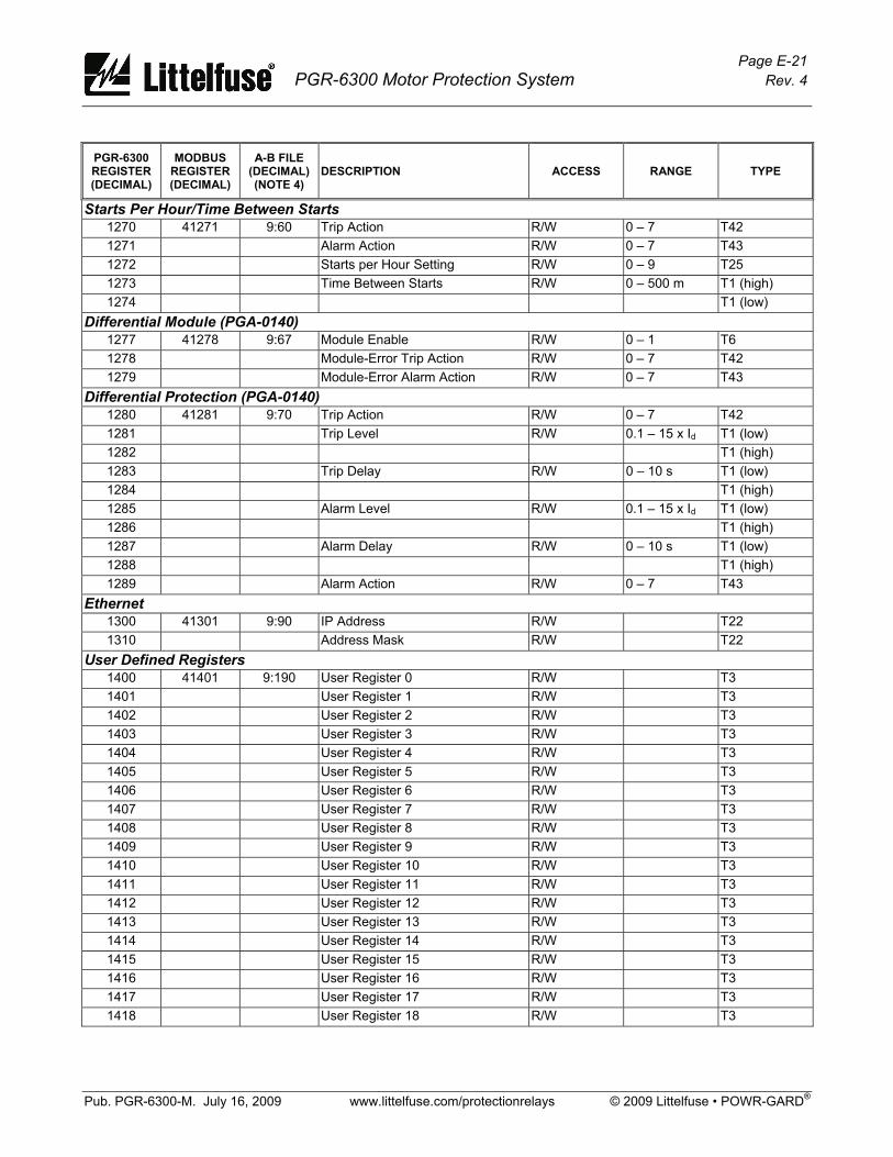
Page E-21 PGR-6300 Motor Protection System Rev. 4
Pub. PGR-6300-M. July 16, 2009 www.littelfuse.com/protectionrelays © 2009 Littelfuse • POWR-GARD®
PGR-6300 REGISTER (DECIMAL)
MODBUS REGISTER (DECIMAL)
A-B FILE (DECIMAL) (NOTE 4)
DESCRIPTION ACCESS RANGE TYPE
Starts Per Hour/Time Between Starts 1270 41271 9:60 Trip Action R/W 0 – 7 T42 1271 Alarm Action R/W 0 – 7 T43 1272 Starts per Hour Setting R/W 0 – 9 T25 1273 Time Between Starts R/W 0 – 500 m T1 (high) 1274 T1 (low)
Differential Module (PGA-0140) 1277 41278 9:67 Module Enable R/W 0 – 1 T6 1278 Module-Error Trip Action R/W 0 – 7 T42 1279 Module-Error Alarm Action R/W 0 – 7 T43
Differential Protection (PGA-0140) 1280 41281 9:70 Trip Action R/W 0 – 7 T42 1281 Trip Level R/W 0.1 – 15 x Id T1 (low) 1282 T1 (high) 1283 Trip Delay R/W 0 – 10 s T1 (low) 1284 T1 (high) 1285 Alarm Level R/W 0.1 – 15 x Id T1 (low) 1286 T1 (high) 1287 Alarm Delay R/W 0 – 10 s T1 (low) 1288 T1 (high) 1289 Alarm Action R/W 0 – 7 T43
Ethernet 1300 41301 9:90 IP Address R/W T22 1310 Address Mask R/W T22
User Defined Registers 1400 41401 9:190 User Register 0 R/W T3 1401 User Register 1 R/W T3 1402 User Register 2 R/W T3 1403 User Register 3 R/W T3 1404 User Register 4 R/W T3 1405 User Register 5 R/W T3 1406 User Register 6 R/W T3 1407 User Register 7 R/W T3 1408 User Register 8 R/W T3 1409 User Register 9 R/W T3 1410 User Register 10 R/W T3 1411 User Register 11 R/W T3 1412 User Register 12 R/W T3 1413 User Register 13 R/W T3 1414 User Register 14 R/W T3 1415 User Register 15 R/W T3 1416 User Register 16 R/W T3 1417 User Register 17 R/W T3 1418 User Register 18 R/W T3

Page E-22 PGR-6300 Motor Protection System Rev. 4
Pub. PGR-6300-M. July 16, 2009 www.littelfuse.com/protectionrelays © 2009 Littelfuse • POWR-GARD®
PGR-6300 REGISTER (DECIMAL)
MODBUS REGISTER (DECIMAL)
A-B FILE (DECIMAL) (NOTE 4)
DESCRIPTION ACCESS RANGE TYPE
1419 User Register 19 R/W T3 1420 User Register 20 R/W T3 1421 User Register 21 R/W T3 1422 User Register 22 R/W T3 1423 User Register 23 R/W T3 1424 User Register 24 R/W T3 1425 User Register 25 R/W T3 1426 User Register 26 R/W T3 1427 User Register 27 R/W T3 1428 User Register 28 R/W T3 1429 User Register 29 R/W T3 1430 User Register 30 R/W T3 1431 User Register 31 R/W T3
User Data 1432 41433 9:222 User Register 0 Data Read Only Range and Type defined by 1433 User Register 1 Data Read Only user register value. 1434 User Register 2 Data Read Only 1435 User Register 3 Data Read Only 1436 User Register 4 Data Read Only 1437 User Register 5 Data Read Only 1438 User Register 6 Data Read Only 1439 User Register 7 Data Read Only 1440 User Register 8 Data Read Only 1441 User Register 9 Data Read Only 1442 User Register 10 Data Read Only 1443 User Register 11 Data Read Only 1444 User Register 12 Data Read Only 1445 User Register 13 Data Read Only 1446 User Register 14 Data Read Only 1447 User Register 15 Data Read Only 1448 User Register 16 Data Read Only 1449 User Register 17 Data Read Only 1450 User Register 18 Data Read Only 1451 User Register 19 Data Read Only 1452 User Register 20 Data Read Only 1453 User Register 21 Data Read Only 1454 User Register 22 Data Read Only 1455 User Register 23 Data Read Only 1456 User Register 24 Data Read Only 1457 User Register 25 Data Read Only 1458 User Register 26 Data Read Only 1459 User Register 27 Data Read Only 1460 User Register 28 Data Read Only 1461 User Register 29 Data Read Only
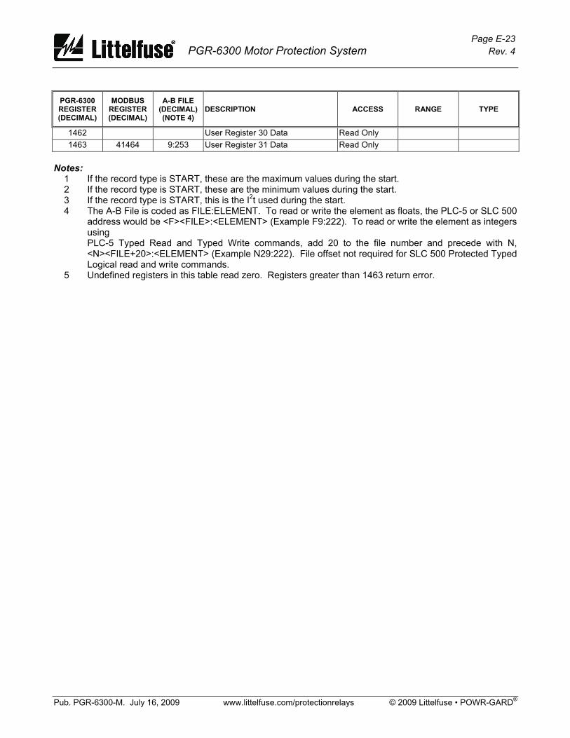
Page E-23 PGR-6300 Motor Protection System Rev. 4
Pub. PGR-6300-M. July 16, 2009 www.littelfuse.com/protectionrelays © 2009 Littelfuse • POWR-GARD®
PGR-6300 REGISTER (DECIMAL)
MODBUS REGISTER (DECIMAL)
A-B FILE (DECIMAL) (NOTE 4)
DESCRIPTION ACCESS RANGE TYPE
1462 User Register 30 Data Read Only 1463 41464 9:253 User Register 31 Data Read Only
Notes: 1 If the record type is START, these are the maximum values during the start. 2 If the record type is START, these are the minimum values during the start. 3 If the record type is START, this is the I2t used during the start. 4 The A-B File is coded as FILE:ELEMENT. To read or write the element as floats, the PLC-5 or SLC 500
address would be <F><FILE>:<ELEMENT> (Example F9:222). To read or write the element as integers using PLC-5 Typed Read and Typed Write commands, add 20 to the file number and precede with N, <N><FILE+20>:<ELEMENT> (Example N29:222). File offset not required for SLC 500 Protected Typed Logical read and write commands.
5 Undefined registers in this table read zero. Registers greater than 1463 return error.

Page E-24 PGR-6300 Motor Protection System Rev. 4
Pub. PGR-6300-M. July 16, 2009 www.littelfuse.com/protectionrelays © 2009 Littelfuse • POWR-GARD®
This page intentionally left blank.
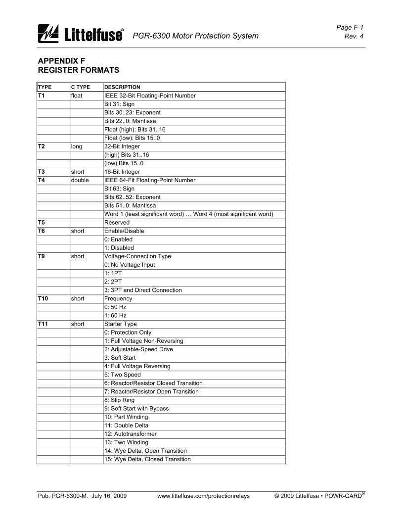
Page F-1 PGR-6300 Motor Protection System Rev. 4
Pub. PGR-6300-M. July 16, 2009 www.littelfuse.com/protectionrelays © 2009 Littelfuse • POWR-GARD®
APPENDIX F REGISTER FORMATS
TYPE C TYPE DESCRIPTION T1 float IEEE 32-Bit Floating-Point Number Bit 31: Sign Bits 30..23: Exponent Bits 22..0: Mantissa Float (high): Bits 31..16 Float (low): Bits 15..0 T2 long 32-Bit Integer (high) Bits 31..16 (low) Bits 15..0 T3 short 16-Bit Integer T4 double IEEE 64-Fit Floating-Point Number Bit 63: Sign Bits 62..52: Exponent Bits 51..0: Mantissa Word 1 (least significant word) … Word 4 (most significant word) T5 Reserved T6 short Enable/Disable 0: Enabled 1: Disabled T9 short Voltage-Connection Type 0: No Voltage Input 1: 1PT 2: 2PT 3: 3PT and Direct Connection T10 short Frequency 0: 50 Hz 1: 60 Hz T11 short Starter Type 0: Protection Only 1: Full Voltage Non-Reversing 2: Adjustable-Speed Drive 3: Soft Start 4: Full Voltage Reversing 5: Two Speed 6: Reactor/Resistor Closed Transition 7: Reactor/Resistor Open Transition 8: Slip Ring 9: Soft Start with Bypass 10: Part Winding 11: Double Delta 12: Autotransformer 13: Two Winding 14: Wye Delta, Open Transition 15: Wye Delta, Closed Transition

Page F-2 PGR-6300 Motor Protection System Rev. 4
Pub. PGR-6300-M. July 16, 2009 www.littelfuse.com/protectionrelays © 2009 Littelfuse • POWR-GARD®
TYPE C TYPE DESCRIPTION T12 short Digital Input Function 0: Input Not Used 1: Start 1 (N.O. Contact) 2: Start 2 (N.O. Contact) 3: Stop (N.C. Contact) 4: Starter RLYA Status 5: Starter RLYB Status 6: Starter RLYC Status 7: Starter RLYD Status 8: Interlock (N.C.) 9: Trip1 (N.C.) 10: Reset (N.O.) 11: Local Select 12: Local Start1 13: Local Start2 14: 2-Wire Start1 15: 2-Wire Start2 16: FLA2 Select 17: Limit1 Stop 18: Limit2 Stop 19: Reduced OC T13 short Relay Output Function 0: None 1: Starter RLYA 2: Starter RLYB 3: Starter RLYC 4: Starter RLYD 5: Trip1 6: Alarm1 7: Trip 2 8: Interlock 9: Local 10: Current Detected 11: Run Mode 12: Starter Sequence Complete 13: Thermal Lockout/Start Inhibit 14: None 15: Watchdog 16: Trip3 17: Alarm2 18: Alarm3 19: Trip1 Pulse 20: Reduced OC T14 short Relay Trip/Alarm Mode 0: Fail Safe 1: Non Fail Safe
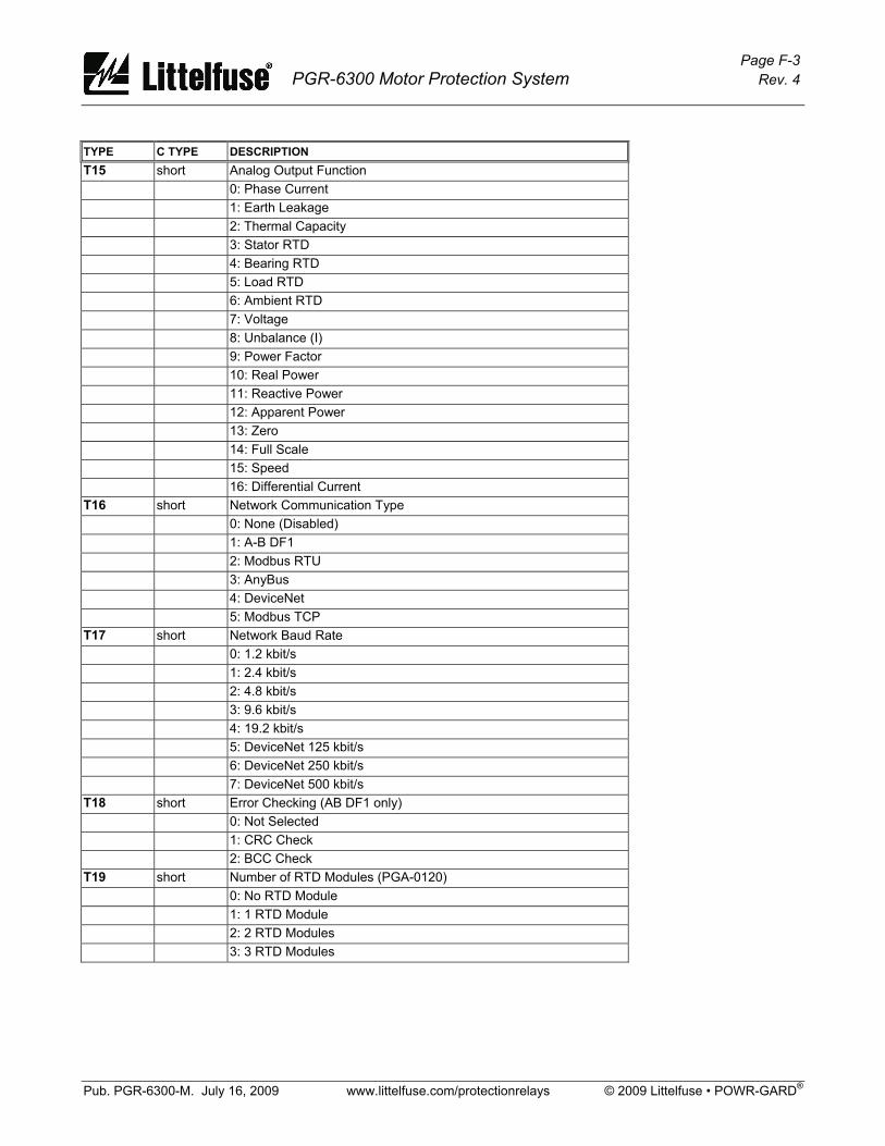
Page F-3 PGR-6300 Motor Protection System Rev. 4
Pub. PGR-6300-M. July 16, 2009 www.littelfuse.com/protectionrelays © 2009 Littelfuse • POWR-GARD®
TYPE C TYPE DESCRIPTION T15 short Analog Output Function 0: Phase Current 1: Earth Leakage 2: Thermal Capacity 3: Stator RTD 4: Bearing RTD 5: Load RTD 6: Ambient RTD 7: Voltage 8: Unbalance (I) 9: Power Factor 10: Real Power 11: Reactive Power 12: Apparent Power 13: Zero 14: Full Scale 15: Speed 16: Differential Current T16 short Network Communication Type 0: None (Disabled) 1: A-B DF1 2: Modbus RTU 3: AnyBus 4: DeviceNet 5: Modbus TCP T17 short Network Baud Rate 0: 1.2 kbit/s 1: 2.4 kbit/s 2: 4.8 kbit/s 3: 9.6 kbit/s 4: 19.2 kbit/s 5: DeviceNet 125 kbit/s 6: DeviceNet 250 kbit/s 7: DeviceNet 500 kbit/s T18 short Error Checking (AB DF1 only) 0: Not Selected 1: CRC Check 2: BCC Check T19 short Number of RTD Modules (PGA-0120) 0: No RTD Module 1: 1 RTD Module 2: 2 RTD Modules 3: 3 RTD Modules

Page F-4 PGR-6300 Motor Protection System Rev. 4
Pub. PGR-6300-M. July 16, 2009 www.littelfuse.com/protectionrelays © 2009 Littelfuse • POWR-GARD®
TYPE C TYPE DESCRIPTION T20 short RTD Type (PGA-0120) 0: Disable 1: Platinum 100 2: Nickel 100 3: Nickel 120 4: Copper 10 T21 short RTD Function (PGA-0120) 0: Stator 1: Bearing 2: Load 3: Ambient T22 char 20 ASCII characters Register +0: char[0] and char[1]. Char [0] at MSByte Register +1: char[2] and char[3]. Char [2] at MSByte Register +2: char[4] and char[5]. Char [4] at MSByte Register +3: char[6] and char[7]. Char [6] at MSByte Register +4: char[8] and char[9]. Char [8] at MSByte Register +5: char[10] and char[11]. Char [10] at MSByte Register +6: char[12] and char[13]. Char [12] at MSByte Register +7: char[14] and char[15]. Char [14] at MSByte Register +8: char[16] and char[17]. Char [16] at MSByte Register +9: char[18] and char[19]. Char [18] at MSByte A character value of 0 (NULL) will terminate the string and the following characters will be ignored. Ethernet address strings are of the form: “ddd.ddd.ddd.ddd”. The MAC address is a hex string of the form: “hhhhhhhhhhhh” T23 long Date Bits 31..16: Year in binary Bits 15..8: 1-12 Months in binary Bits 7..0: 1-31 days in binary T24 long Time Bits 31..24: 0-23 hours in binary Bits 23..16: 0-60 minutes in binary Bits 15..8: 0-60 seconds in binary Bits 7..0: 0-99 hundredths of seconds in binary T25 Short Starts Per Hour 0: 1 Start per hour 1: 2 Starts per hour 2: 3 Starts per hour 3: 4 Starts per hour 4: 5 Starts per hour 5: 6 Starts per hour 6: 7 Starts per hour 7: 8 Starts per hour 8: 9 Starts per hour 9: 10 Starts per hour

Page F-5 PGR-6300 Motor Protection System Rev. 4
Pub. PGR-6300-M. July 16, 2009 www.littelfuse.com/protectionrelays © 2009 Littelfuse • POWR-GARD®
TYPE C TYPE DESCRIPTION T26 short Trigger Source 0: Empty Record 1: Trip Record 2: Start Record 3: ETR Record T27 short Message Code 0: Main Overcurrent Trip 1: Auxiliary Overcurrent Trip 2: Overload Trip 3: Overload Alarm 4: Earth-Fault Trip 5: Earth-Fault Alarm 6: Current-Unbalance Trip 7: Current-Unbalance Alarm 8: Voltage-Unbalance Trip 9: Voltage-Unbalance Alarm 10: Jam Trip 11: Jam Alarm 12: Undercurrent Trip 13: Undercurrent Alarm 14: Overvoltage Trip 15: Overvoltage Alarm 16: Undervoltage Trip 17: Undervoltage Alarm 18: Analog-Input-High Trip 19: Analog-Input-High Alarm 20: Analog-Input-Low Trip 21: Analog-Input-Low Alarm 22: PTC Temperature Trip 23: PTC Temperature Alarm 24: Phase-Loss (Current) Trip 25: Phase-Reverse (Current) Trip 26: Phase-Loss (Voltage) Trip 27: Phase-Reverse (Voltage) Trip 28: Underspeed Trip 29: Relay-Status Trip 30: Digital 1 Trip 31: Digital 2 Trip 32: Digital 3 Trip 33: Digital 4 Trip 34: Digital 5 Trip 35: Digital 6 Trip 36: Digital 7 Trip 37: RTD Module 1 INP 1 Trip (PGA-0120) 38: RTD Module 1 INP 1 Alarm 39: RTD Module 1 INP 2 Trip 40: RTD Module 1 INP 2 Alarm
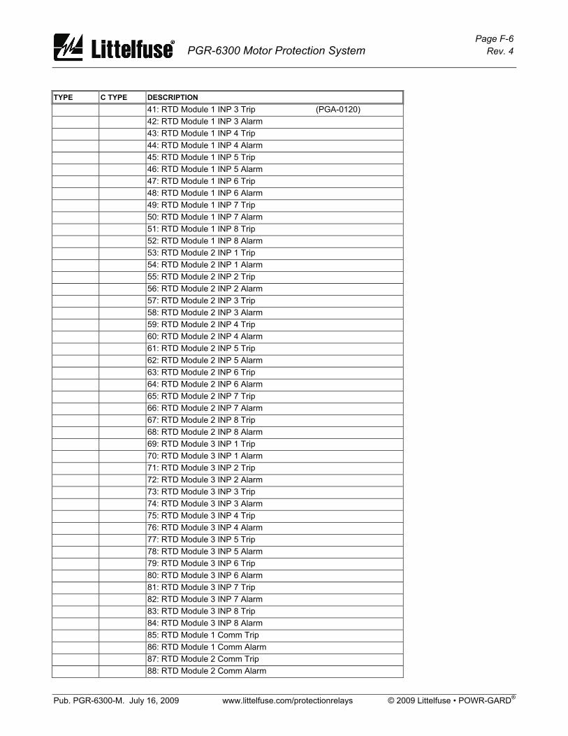
Page F-6 PGR-6300 Motor Protection System Rev. 4
Pub. PGR-6300-M. July 16, 2009 www.littelfuse.com/protectionrelays © 2009 Littelfuse • POWR-GARD®
TYPE C TYPE DESCRIPTION 41: RTD Module 1 INP 3 Trip (PGA-0120) 42: RTD Module 1 INP 3 Alarm 43: RTD Module 1 INP 4 Trip 44: RTD Module 1 INP 4 Alarm 45: RTD Module 1 INP 5 Trip 46: RTD Module 1 INP 5 Alarm 47: RTD Module 1 INP 6 Trip 48: RTD Module 1 INP 6 Alarm 49: RTD Module 1 INP 7 Trip 50: RTD Module 1 INP 7 Alarm 51: RTD Module 1 INP 8 Trip 52: RTD Module 1 INP 8 Alarm 53: RTD Module 2 INP 1 Trip 54: RTD Module 2 INP 1 Alarm 55: RTD Module 2 INP 2 Trip 56: RTD Module 2 INP 2 Alarm 57: RTD Module 2 INP 3 Trip 58: RTD Module 2 INP 3 Alarm 59: RTD Module 2 INP 4 Trip 60: RTD Module 2 INP 4 Alarm 61: RTD Module 2 INP 5 Trip 62: RTD Module 2 INP 5 Alarm 63: RTD Module 2 INP 6 Trip 64: RTD Module 2 INP 6 Alarm 65: RTD Module 2 INP 7 Trip 66: RTD Module 2 INP 7 Alarm 67: RTD Module 2 INP 8 Trip 68: RTD Module 2 INP 8 Alarm 69: RTD Module 3 INP 1 Trip 70: RTD Module 3 INP 1 Alarm 71: RTD Module 3 INP 2 Trip 72: RTD Module 3 INP 2 Alarm 73: RTD Module 3 INP 3 Trip 74: RTD Module 3 INP 3 Alarm 75: RTD Module 3 INP 4 Trip 76: RTD Module 3 INP 4 Alarm 77: RTD Module 3 INP 5 Trip 78: RTD Module 3 INP 5 Alarm 79: RTD Module 3 INP 6 Trip 80: RTD Module 3 INP 6 Alarm 81: RTD Module 3 INP 7 Trip 82: RTD Module 3 INP 7 Alarm 83: RTD Module 3 INP 8 Trip 84: RTD Module 3 INP 8 Alarm 85: RTD Module 1 Comm Trip 86: RTD Module 1 Comm Alarm 87: RTD Module 2 Comm Trip 88: RTD Module 2 Comm Alarm
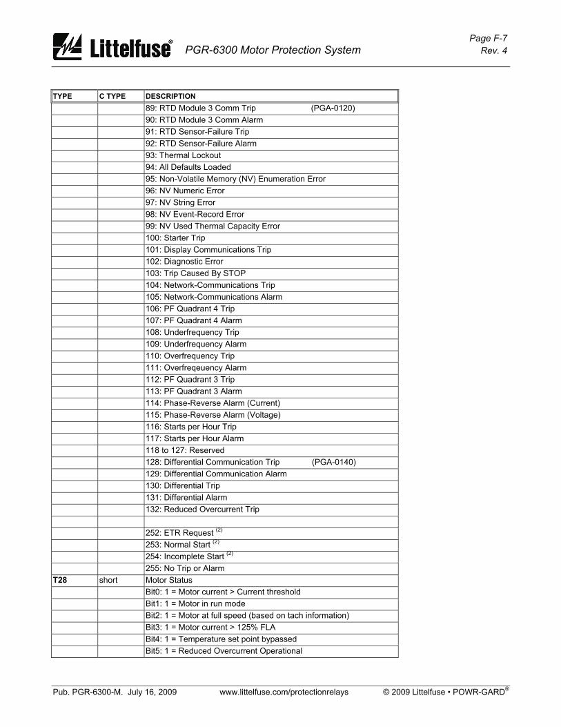
Page F-7 PGR-6300 Motor Protection System Rev. 4
Pub. PGR-6300-M. July 16, 2009 www.littelfuse.com/protectionrelays © 2009 Littelfuse • POWR-GARD®
TYPE C TYPE DESCRIPTION 89: RTD Module 3 Comm Trip (PGA-0120) 90: RTD Module 3 Comm Alarm 91: RTD Sensor-Failure Trip 92: RTD Sensor-Failure Alarm 93: Thermal Lockout 94: All Defaults Loaded 95: Non-Volatile Memory (NV) Enumeration Error 96: NV Numeric Error 97: NV String Error 98: NV Event-Record Error 99: NV Used Thermal Capacity Error 100: Starter Trip 101: Display Communications Trip 102: Diagnostic Error 103: Trip Caused By STOP 104: Network-Communications Trip 105: Network-Communications Alarm 106: PF Quadrant 4 Trip 107: PF Quadrant 4 Alarm 108: Underfrequency Trip 109: Underfrequency Alarm 110: Overfrequency Trip 111: Overfreqeuency Alarm 112: PF Quadrant 3 Trip 113: PF Quadrant 3 Alarm 114: Phase-Reverse Alarm (Current) 115: Phase-Reverse Alarm (Voltage) 116: Starts per Hour Trip 117: Starts per Hour Alarm 118 to 127: Reserved 128: Differential Communication Trip (PGA-0140) 129: Differential Communication Alarm 130: Differential Trip 131: Differential Alarm 132: Reduced Overcurrent Trip 252: ETR Request (2)
253: Normal Start (2)
254: Incomplete Start (2)
255: No Trip or Alarm T28 short Motor Status Bit0: 1 = Motor current > Current threshold Bit1: 1 = Motor in run mode Bit2: 1 = Motor at full speed (based on tach information) Bit3: 1 = Motor current > 125% FLA Bit4: 1 = Temperature set point bypassed Bit5: 1 = Reduced Overcurrent Operational
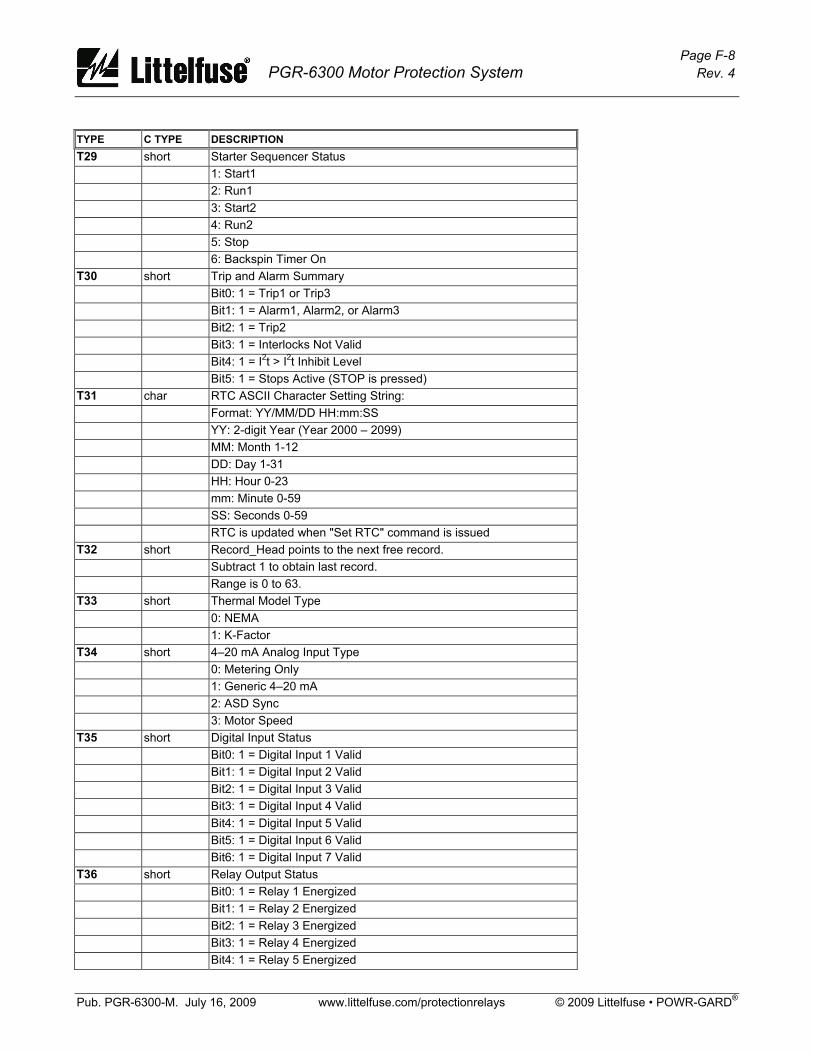
Page F-8 PGR-6300 Motor Protection System Rev. 4
Pub. PGR-6300-M. July 16, 2009 www.littelfuse.com/protectionrelays © 2009 Littelfuse • POWR-GARD®
TYPE C TYPE DESCRIPTION T29 short Starter Sequencer Status 1: Start1 2: Run1 3: Start2 4: Run2 5: Stop 6: Backspin Timer On T30 short Trip and Alarm Summary Bit0: 1 = Trip1 or Trip3 Bit1: 1 = Alarm1, Alarm2, or Alarm3 Bit2: 1 = Trip2 Bit3: 1 = Interlocks Not Valid Bit4: 1 = I2t > I2t Inhibit Level Bit5: 1 = Stops Active (STOP is pressed) T31 char RTC ASCII Character Setting String: Format: YY/MM/DD HH:mm:SS YY: 2-digit Year (Year 2000 – 2099) MM: Month 1-12 DD: Day 1-31 HH: Hour 0-23 mm: Minute 0-59 SS: Seconds 0-59 RTC is updated when "Set RTC" command is issued T32 short Record_Head points to the next free record. Subtract 1 to obtain last record. Range is 0 to 63. T33 short Thermal Model Type 0: NEMA 1: K-Factor T34 short 4–20 mA Analog Input Type 0: Metering Only 1: Generic 4–20 mA 2: ASD Sync 3: Motor Speed T35 short Digital Input Status Bit0: 1 = Digital Input 1 Valid Bit1: 1 = Digital Input 2 Valid Bit2: 1 = Digital Input 3 Valid Bit3: 1 = Digital Input 4 Valid Bit4: 1 = Digital Input 5 Valid Bit5: 1 = Digital Input 6 Valid Bit6: 1 = Digital Input 7 Valid T36 short Relay Output Status Bit0: 1 = Relay 1 Energized Bit1: 1 = Relay 2 Energized Bit2: 1 = Relay 3 Energized Bit3: 1 = Relay 4 Energized Bit4: 1 = Relay 5 Energized
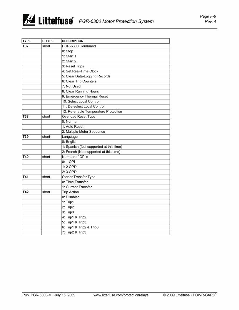
Page F-9 PGR-6300 Motor Protection System Rev. 4
Pub. PGR-6300-M. July 16, 2009 www.littelfuse.com/protectionrelays © 2009 Littelfuse • POWR-GARD®
TYPE C TYPE DESCRIPTION T37 short PGR-6300 Command 0: Stop 1: Start 1 2: Start 2 3: Reset Trips 4: Set Real-Time Clock 5: Clear Data-Logging Records 6: Clear Trip Counters 7: Not Used 8: Clear Running Hours 9: Emergency Thermal Reset 10: Select Local Control 11: De-select Local Control 12: Re-enable Temperature Protection T38 short Overload Reset Type 0: Normal 1: Auto Reset 2: Multiple-Motor Sequence T39 short Language 0: English 1: Spanish (Not supported at this time) 2: French (Not supported at this time) T40 short Number of OPI’s 0: 1 OPI 1: 2 OPI’s 2: 3 OPI’s T41 short Starter Transfer Type 0: Time Transfer 1: Current Transfer T42 short Trip Action 0: Disabled 1: Trip1 2: Trip2 3: Trip3 4: Trip1 & Trip2 5: Trip1 & Trip3 6: Trip1 & Trip2 & Trip3 7: Trip2 & Trip3
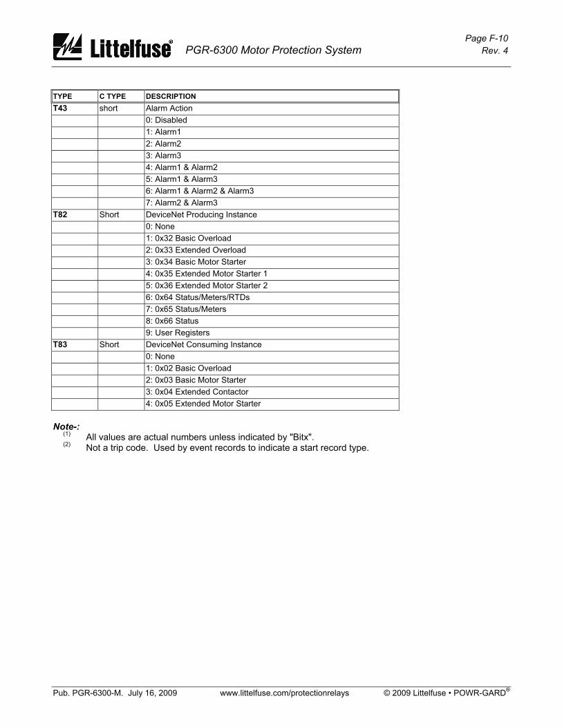
Page F-10 PGR-6300 Motor Protection System Rev. 4
Pub. PGR-6300-M. July 16, 2009 www.littelfuse.com/protectionrelays © 2009 Littelfuse • POWR-GARD®
TYPE C TYPE DESCRIPTION T43 short Alarm Action 0: Disabled 1: Alarm1 2: Alarm2 3: Alarm3 4: Alarm1 & Alarm2 5: Alarm1 & Alarm3 6: Alarm1 & Alarm2 & Alarm3 7: Alarm2 & Alarm3 T82 Short DeviceNet Producing Instance 0: None 1: 0x32 Basic Overload 2: 0x33 Extended Overload 3: 0x34 Basic Motor Starter 4: 0x35 Extended Motor Starter 1 5: 0x36 Extended Motor Starter 2 6: 0x64 Status/Meters/RTDs 7: 0x65 Status/Meters 8: 0x66 Status 9: User Registers T83 Short DeviceNet Consuming Instance 0: None 1: 0x02 Basic Overload 2: 0x03 Basic Motor Starter 3: 0x04 Extended Contactor 4: 0x05 Extended Motor Starter Note-: (1) All values are actual numbers unless indicated by "Bitx". (2) Not a trip code. Used by event records to indicate a start record type.