phase 2 improvements new administration building · phase 2 improvements new administration...
TRANSCRIPT

June 10, 2016
PHASE 2 IMPROVEMENTS
NEW ADMINISTRATION BUILDING
Wernle Youth & Family Treatment Center
Richmond, Indiana
Project ManualVolume 2 of 2

TABLE OF CONTENTS
Page
VOLUME 2 OF 2
DIVISION XXI - FIRE SUPPRESSION
Common Work Results for Fire Suppression . . . . . . . . . . . . . . . . . . . . . . . . . . . . . . . . . . 21050-1 thru 21050-8
Dry-Pipe Sprinkler Systems . . . . . . . . . . . . . . . . . . . . . . . . . . . . . . . . . . . . . . . . . . . . . . . 21131-1 thru 21131-22
DIVISION XXII - PLUMBING
Common Work Results for Plumbing . . . . . . . . . . . . . . . . . . . . . . . . . . . . . . . . . . . . . . . 22050-1 thru 22050-13
Meters and Gages for Plumbing Piping . . . . . . . . . . . . . . . . . . . . . . . . . . . . . . . . . . . . . . 22051-1 thru 22051-6
General - Duty Valves for Plumbing Piping . . . . . . . . . . . . . . . . . . . . . . . . . . . . . . . . . . . 22052-1 thru 22052-7
Identification for Plumbing Piping and Equipment . . . . . . . . . . . . . . . . . . . . . . . . . . . . . 22055-1 thru 22055-5
Domestic Water Piping . . . . . . . . . . . . . . . . . . . . . . . . . . . . . . . . . . . . . . . . . . . . . . . . . . . 22116-1 thru 22116-13
Domestic Water Pumps . . . . . . . . . . . . . . . . . . . . . . . . . . . . . . . . . . . . . . . . . . . . . . . . . . 22123-1 thru 22123-4
Domestic Water Softeners . . . . . . . . . . . . . . . . . . . . . . . . . . . . . . . . . . . . . . . . . . . . . . . . 22310-1 thru 22310-6
Sanitary Waste and Vent Piping . . . . . . . . . . . . . . . . . . . . . . . . . . . . . . . . . . . . . . . . . . . 22316-1 thru 22316-11
Sanitary Waste Piping Specialties . . . . . . . . . . . . . . . . . . . . . . . . . . . . . . . . . . . . . . . . . . 22319-1 thru 22319-9
Electric Domestic - Water Heaters . . . . . . . . . . . . . . . . . . . . . . . . . . . . . . . . . . . . . . . . . . 22330-1 thru 22330-7
Commercial Sinks . . . . . . . . . . . . . . . . . . . . . . . . . . . . . . . . . . . . . . . . . . . . . . . . . . . . . . 22417-1 thru 22417-6
Commercial Urinals . . . . . . . . . . . . . . . . . . . . . . . . . . . . . . . . . . . . . . . . . . . . . . . . . . . . . 22421-1 thru 22421-4
Pressure Water Coolers . . . . . . . . . . . . . . . . . . . . . . . . . . . . . . . . . . . . . . . . . . . . . . . . . . 22471-1 thru 22471-4
DIVISION XXIII - HEATING, VENTILATING AND AIR CONDITIONING
Common Work Results for HVAC . . . . . . . . . . . . . . . . . . . . . . . . . . . . . . . . . . . . . . . . . . 23050-1 thru 23050-16
Meters and Gauges for HVAC Piping . . . . . . . . . . . . . . . . . . . . . . . . . . . . . . . . . . . . . . . . 23051-1 thru 23051-5
Common Motor Requirements for HVAC Equipment . . . . . . . . . . . . . . . . . . . . . . . . . . . 23053-1 thru 23053-3
Identification for HVAC Piping and Equipment . . . . . . . . . . . . . . . . . . . . . . . . . . . . . . . . 23055-1 thru 23055-6
Testing, Adjusting, and Balancing for HVAC . . . . . . . . . . . . . . . . . . . . . . . . . . . . . . . . . . 23059-1 thru 23059-17
Duct Insulation . . . . . . . . . . . . . . . . . . . . . . . . . . . . . . . . . . . . . . . . . . . . . . . . . . . . . . . . . 23073-1 thru 23073-12
Instrumentation and Controls for HVAC . . . . . . . . . . . . . . . . . . . . . . . . . . . . . . . . . . . . . . 23090-1 thru 23090-22
Sequence of Operations for HVAC Controls . . . . . . . . . . . . . . . . . . . . . . . . . . . . . . . . . . 23093-1 thru 23093-6
Facility Natural-Gas Piping . . . . . . . . . . . . . . . . . . . . . . . . . . . . . . . . . . . . . . . . . . . . . . . . 23123-1 thru 23123-15
Hydronic Piping . . . . . . . . . . . . . . . . . . . . . . . . . . . . . . . . . . . . . . . . . . . . . . . . . . . . . . . . 23211-1 thru 23211-9
Hydronic Pumps . . . . . . . . . . . . . . . . . . . . . . . . . . . . . . . . . . . . . . . . . . . . . . . . . . . . . . . . 23212-1 thru 23212-4
Hydronic Piping Specialties . . . . . . . . . . . . . . . . . . . . . . . . . . . . . . . . . . . . . . . . . . . . . . . 23216-1 thru 23216-6
Refrigerant Piping . . . . . . . . . . . . . . . . . . . . . . . . . . . . . . . . . . . . . . . . . . . . . . . . . . . . . . . 23230-1 thru 23230-8
Water Treatment for Closed-Loop Hydronic Systems . . . . . . . . . . . . . . . . . . . . . . . . . . . 23251-1 thru 23251-5
Air Duct Accessories . . . . . . . . . . . . . . . . . . . . . . . . . . . . . . . . . . . . . . . . . . . . . . . . . . . . 23330-1 thru 23330-9
Fixed Louvers . . . . . . . . . . . . . . . . . . . . . . . . . . . . . . . . . . . . . . . . . . . . . . . . . . . . . . . . . . 23341-1 thru 23341-3
HVAC Power Ventilators . . . . . . . . . . . . . . . . . . . . . . . . . . . . . . . . . . . . . . . . . . . . . . . . . . 23343-1 thru 23343-5
Air Terminal Units . . . . . . . . . . . . . . . . . . . . . . . . . . . . . . . . . . . . . . . . . . . . . . . . . . . . . . . 23360-1 thru 23360-5
HVAC Gravity Ventilators . . . . . . . . . . . . . . . . . . . . . . . . . . . . . . . . . . . . . . . . . . . . . . . . . 23372-1 thru 23372-3
Diffusers, Registers, and Grilles . . . . . . . . . . . . . . . . . . . . . . . . . . . . . . . . . . . . . . . . . . . . 23373-1 thru 23373-4
Condensing Boilers . . . . . . . . . . . . . . . . . . . . . . . . . . . . . . . . . . . . . . . . . . . . . . . . . . . . . 23521-1 thru 23521-7
Packaged Compressor and Condenser Units . . . . . . . . . . . . . . . . . . . . . . . . . . . . . . . . . 23620-1 thru 23620-6
Modular Indoor Central-Station Air Handling Units . . . . . . . . . . . . . . . . . . . . . . . . . . . . . 23731-1 thru 23731-9
Split-System Air Conditioners . . . . . . . . . . . . . . . . . . . . . . . . . . . . . . . . . . . . . . . . . . . . . . 23812-1 thru 23812-5
Cabinet Unit Heaters . . . . . . . . . . . . . . . . . . . . . . . . . . . . . . . . . . . . . . . . . . . . . . . . . . . . 23823-1 thru 23823-5
TABLE OF CONTENTS Page
DIVISION XXIV - DIVISION XXV . . . . . . . . . . . . . . . . . . . . . . . . . . . . . . . . . . . . . . . . . . . . Not Used
DIVISION XXVI - ELECTRICAL
Basic Electrical Requirements . . . . . . . . . . . . . . . . . . . . . . . . . . . . . . . . . . . . . . . . . . . . . 26050-1 thru 26050-14
Conductors and Cables . . . . . . . . . . . . . . . . . . . . . . . . . . . . . . . . . . . . . . . . . . . . . . . . . . 26051-1 thru 26051-5
Raceway and Boxes . . . . . . . . . . . . . . . . . . . . . . . . . . . . . . . . . . . . . . . . . . . . . . . . . . . . . 26053-1 thru 26053-10
Grounding and Bonding . . . . . . . . . . . . . . . . . . . . . . . . . . . . . . . . . . . . . . . . . . . . . . . . . 26056-1 thru 26056-9
Lighting Control Devices . . . . . . . . . . . . . . . . . . . . . . . . . . . . . . . . . . . . . . . . . . . . . . . . . 26092-1 thru 26092-6
Panelboards . . . . . . . . . . . . . . . . . . . . . . . . . . . . . . . . . . . . . . . . . . . . . . . . . . . . . . . . . . . 26246-1 thru 26246-10
Wiring Devices . . . . . . . . . . . . . . . . . . . . . . . . . . . . . . . . . . . . . . . . . . . . . . . . . . . . . . . . . 26276-1 thru 26276-6
Fuses . . . . . . . . . . . . . . . . . . . . . . . . . . . . . . . . . . . . . . . . . . . . . . . . . . . . . . . . . . . . . . . . 26283-1 thru 26283-5
Enclosed Switches and Circuit Breakers . . . . . . . . . . . . . . . . . . . . . . . . . . . . . . . . . . . . . 26286-1 thru 26286-9
Interior Lighting . . . . . . . . . . . . . . . . . . . . . . . . . . . . . . . . . . . . . . . . . . . . . . . . . . . . . . . . 26510-1 thru 26510-10
Exterior Lighting . . . . . . . . . . . . . . . . . . . . . . . . . . . . . . . . . . . . . . . . . . . . . . . . . . . . . . . . 26560-1 thru 26560-9
DIVISION XXVII . . . . . . . . . . . . . . . . . . . . . . . . . . . . . . . . . . . . . . . . . . . . . . . . . . . . . . . . . Not Used
DIVISION XXVIII - ELECTRONIC SAFETY AND SECURITY
Fire Alarm System . . . . . . . . . . . . . . . . . . . . . . . . . . . . . . . . . . . . . . . . . . . . . . . . . . . . . . 28311-1 thru 28311-16
21050 - 1
SECTION 21050 - COMMON WORK RESULTS FOR FIRE SUPPRESSION
PART 1 - GENERAL
1.1 RELATED DOCUMENTS
A. Drawings and general provisions of the Contract, including General and Supplementary
Conditions and Division 01 Specification Sections, apply to this Section.
1.2 SUMMARY
A. This Section includes the following:
1. Piping materials and installation instructions common to most piping systems.
2. Mechanical sleeve seals.
3. Sleeves.
4. Escutcheons.
5. Grout.
6. Equipment installation requirements common to equipment sections.
7. Painting and finishing.
8. Concrete bases. 9. Supports and anchorages.
1.3 DEFINITIONS
A. Finished Spaces: Spaces other than mechanical and electrical equipment rooms, furred
spaces, pipe chases, unheated spaces immediately below roof, spaces above ceilings,
unexcavated spaces, crawlspaces, and tunnels.
B. Exposed, Interior Installations: Exposed to view indoors. Examples include finished occupied
spaces and mechanical equipment rooms.
C. Exposed, Exterior Installations: Exposed to view outdoors or subject to outdoor ambient
temperatures and weather conditions. Examples include rooftop locations.
D. Concealed, Interior Installations: Concealed from view and protected from physical contact by
building occupants. Examples include above ceilings and in chases.
E. Concealed, Exterior Installations: Concealed from view and protected from weather conditions
and physical contact by building occupants but subject to outdoor ambient temperatures.
Examples include installations within unheated shelters.
F. The following are industry abbreviations for plastic materials:
1. CPVC: Chlorinated polyvinyl chloride plastic.
G. The following are industry abbreviations for rubber materials:
1. EPDM: Ethylene-propylene-diene terpolymer rubber.
2. NBR: Acrylonitrile-butadiene rubber.

21050 - 2
1.4 SUBMITTALS
A. Product Data: For the following:
1. Mechanical sleeve seals.
2. Escutcheons.
B. Welding certificates.
1.5 QUALITY ASSURANCE
A. Steel Support Welding: Qualify processes and operators according to AWS D1.1, "Structural
Welding Code--Steel."
B. Electrical Characteristics for Fire-Suppression Equipment: Equipment of different electrical
characteristics may be furnished provided such proposed equipment is approved in writing
and connecting electrical services, circuit breakers, and conduit sizes are appropriately
modified at the cost of the equipment manufacturer. If minimum energy ratings or efficiencies
are specified, equipment shall comply with requirements.
1.6 DELIVERY, STORAGE, AND HANDLING
A. Deliver pipes and tubes with factory-applied end caps. Maintain end caps through shipping, storage, and handling to prevent pipe end damage and to prevent entrance of dirt, debris, and
moisture.
1.7 COORDINATION
A. Arrange for pipe spaces, chases, slots, and openings in building structure during progress of
construction, to allow for fire-suppression installations.
B. Coordinate installation of required supporting devices and set sleeves in poured-in-place
concrete and other structural components as they are constructed.
C. Coordinate requirements for access panels and doors for fire-suppression items requiring
access that are concealed behind finished surfaces. Access panels and doors are specified in Division 08 Section "Access Doors and Frames."
PART 2 - PRODUCTS
2.1 MANUFACTURERS
A. In other Part 2 articles where subparagraph titles below introduce lists, the following
requirements apply for product selection:
1. Manufacturers: Subject to compliance with requirements, provide products by the
manufacturers specified.
2.2 PIPE, TUBE, AND FITTINGS
21050 - 3
A. Refer to individual Division 21 piping Sections for pipe, tube, and fitting materials and joining
methods.
B. Pipe Threads: ASME B1.20.1 for factory-threaded pipe and pipe fittings.
2.3 JOINING MATERIALS
A. Refer to individual Division 21 piping Sections for special joining materials not listed below.
B. Pipe-Flange Gasket Materials: Suitable for chemical and thermal conditions of piping system
contents.
1. ASME B16.21, nonmetallic, flat, asbestos-free, 1/8-inch maximum thickness unless
thickness or specific material is indicated.
a. Full-Face Type: For flat-face, Class 125, cast-iron and cast-bronze flanges.
b. Narrow-Face Type: For raised-face, Class 250, cast-iron and steel flanges.
2. AWWA C110, rubber, flat face, 1/8 inch thick, unless otherwise indicated; and full-face or
ring type, unless otherwise indicated.
C. Flange Bolts and Nuts: ASME B18.2.1, carbon steel, unless otherwise indicated.
D. Solder Filler Metals: ASTM B 32, lead-free alloys. Include water-flushable flux according to ASTM B 813.
E. Brazing Filler Metals: AWS A5.8, BCuP Series, copper-phosphorus alloys for general-duty
brazing, unless otherwise indicated; and AWS A5.8, BAg1, silver alloy for refrigerant piping,
unless otherwise indicated.
F. Welding Filler Metals: Comply with AWS D10.12 for welding materials appropriate for wall
thickness and chemical analysis of steel pipe being welded.
2.4 MECHANICAL SLEEVE SEALS
A. Description: Modular sealing element unit, designed for field assembly, to fill annular space
between pipe and sleeve.
1. Manufacturers:
a. Advance Products & Systems, Inc.
b. Calpico, Inc.
c. Metraflex Co.
d. Pipeline Seal and Insulator, Inc.
2. Sealing Elements: EPDM or NBR interlocking links shaped to fit surface of pipe. Include
type and number required for pipe material and size of pipe.
3. Pressure Plates: Carbon steel. Include two for each sealing element.
4. Connecting Bolts and Nuts: Carbon steel with corrosion-resistant coating of length
required to secure pressure plates to sealing elements. Include one for each sealing element.
2.5 SLEEVES
21050 - 4
A. Galvanized-Steel Sheet: 0.0239-inch minimum thickness; round tube closed with welded
longitudinal joint.
B. Steel Pipe: ASTM A 53, Type E, Grade B, Schedule 40, galvanized, plain ends.
C. Cast Iron: Cast or fabricated "wall pipe" equivalent to ductile-iron pressure pipe, with plain
ends and integral waterstop, unless otherwise indicated.
D. Stack Sleeve Fittings: Manufactured, cast-iron sleeve with integral clamping flange. Include
clamping ring and bolts and nuts for membrane flashing.
1. Underdeck Clamp: Clamping ring with set screws.
2.6 ESCUTCHEONS
A. Description: Manufactured wall and ceiling escutcheons and floor plates, with an ID to closely
fit around pipe, tube, and insulation of insulated piping and an OD that completely covers
opening.
B. One-Piece, Deep-Pattern Type: Deep-drawn, box-shaped brass with polished chrome-plated
finish.
C. One-Piece, Cast-Brass Type: With set screw.
1. Finish: Polished chrome-plated.
D. Split-Casting, Cast-Brass Type: With concealed hinge and set screw.
1. Finish: Polished chrome-plated.
E. One-Piece, Stamped-Steel Type: With set screw or spring clips and chrome-plated finish.
F. Split-Plate, Stamped-Steel Type: With concealed hinge, set screw or spring clips, and chrome-
plated finish.
G. One-Piece, Floor-Plate Type: Cast-iron floor plate.
H. Split-Casting, Floor-Plate Type: Cast brass with concealed hinge and set screw.
2.7 GROUT
A. Description: ASTM C 1107, Grade B, nonshrink and nonmetallic, dry hydraulic-cement grout.
1. Characteristics: Post-hardening, volume-adjusting, nonstaining, noncorrosive,
nongaseous, and recommended for interior and exterior applications.
2. Design Mix: 5000-psi, 28-day compressive strength.
3. Packaging: Premixed and factory packaged.
PART 3 - EXECUTION
3.1 PIPING SYSTEMS - COMMON REQUIREMENTS
21050 - 5
A. Install piping according to the following requirements and Division 21 Sections specifying
piping systems.
B. Drawing plans, schematics, and diagrams indicate general location and arrangement of piping
systems. Indicated locations and arrangements were used to size pipe and calculate friction
loss, expansion, pump sizing, and other design considerations. Install piping as indicated unless deviations to layout are approved on Coordination Drawings.
C. Install piping in concealed locations, unless otherwise indicated and except in equipment
rooms and service areas.
D. Install piping indicated to be exposed and piping in equipment rooms and service areas at
right angles or parallel to building walls. Diagonal runs are prohibited unless specifically
indicated otherwise.
E. Install piping above accessible ceilings to allow sufficient space for ceiling panel removal.
F. Install piping to permit valve servicing.
G. Install piping at indicated slopes.
H. Install piping free of sags and bends.
I. Install fittings for changes in direction and branch connections.
J. Install piping to allow application of insulation.
K. Select system components with pressure rating equal to or greater than system operating
pressure.
L. Install escutcheons for penetrations of walls, ceilings, and floors according to the following:
1. New Piping:
a. Piping with Fitting or Sleeve Protruding from Wall: One-piece, deep-pattern type.
b. Chrome-Plated Piping: One-piece, cast-brass type with polished chrome-plated
finish. c. Insulated Piping: One-piece, stamped-steel type with spring clips.
d. Bare Piping at Wall and Floor Penetrations in Finished Spaces: One-piece, cast-
brass type with polished chrome-plated finish.
e. Bare Piping at Ceiling Penetrations in Finished Spaces: One-piece or split-
casting, cast-brass type with polished chrome-plated finish.
f. Bare Piping in Unfinished Service Spaces: One-piece, cast-brass type with
polished chrome-plated finish.
g. Bare Piping in Equipment Rooms: One-piece, cast-brass type.
h. Bare Piping at Floor Penetrations in Equipment Rooms: One-piece, floor-plate
type.
M. Sleeves are not required for core-drilled holes.
N. Install sleeves for pipes passing through concrete and masonry walls and concrete floor and
roof slabs.
1. Cut sleeves to length for mounting flush with both surfaces.
21050 - 6
a. Exception: Extend sleeves installed in floors of mechanical equipment areas or
other wet areas 2 inches above finished floor level. Extend cast-iron sleeve fittings
below floor slab as required to secure clamping ring if ring is specified.
2. Install sleeves in new walls and slabs as new walls and slabs are constructed.
3. Install sleeves that are large enough to provide 1/4-inch annular clear space between sleeve and pipe or pipe insulation. Use the following sleeve materials:
a. Steel Pipe Sleeves: For pipes smaller than NPS 6.
b. Steel Sheet Sleeves: For pipes NPS 6 and larger, penetrating gypsum-board
partitions.
c. Stack Sleeve Fittings: For pipes penetrating floors with membrane waterproofing.
Secure flashing between clamping flanges. Install section of cast-iron soil pipe to
extend sleeve to 2 inches above finished floor level. Refer to Division 07 Section
"Sheet Metal Flashing and Trim" for flashing.
1) Seal space outside of sleeve fittings with grout.
4. Seal annular space between sleeve and pipe or pipe insulation, using joint sealants appropriate for size, depth, and location of joint. Refer to Division 07 Section "Joint
Sealants" for materials and installation.
O. Aboveground, Exterior-Wall Pipe Penetrations: Seal penetrations using sleeves and
mechanical sleeve seals. Select sleeve size to allow for 1-inch annular clear space between
pipe and sleeve for installing mechanical sleeve seals.
1. Install steel pipe for sleeves smaller than 6 inches in diameter.
2. Install cast-iron "wall pipes" for sleeves 6 inches and larger in diameter.
3. Mechanical Sleeve Seal Installation: Select type and number of sealing elements
required for pipe material and size. Position pipe in center of sleeve. Assemble mechanical sleeve seals and install in annular space between pipe and sleeve. Tighten
bolts against pressure plates that cause sealing elements to expand and make
watertight seal.
P. Fire-Barrier Penetrations: Maintain indicated fire rating of walls, partitions, ceilings, and floors
at pipe penetrations. Seal pipe penetrations with firestop materials. Refer to Division 07
Section "Penetration Firestopping" for materials.
Q. Verify final equipment locations for roughing-in.
R. Refer to equipment specifications in other Sections of these Specifications for roughing-in
requirements.
3.2 PIPING JOINT CONSTRUCTION
A. Join pipe and fittings according to the following requirements and Division 21 Sections
specifying piping systems.
B. Ream ends of pipes and tubes and remove burrs. Bevel plain ends of steel pipe.
C. Remove scale, slag, dirt, and debris from inside and outside of pipe and fittings before
assembly.

21050 - 7
D. Soldered Joints: Apply ASTM B 813, water-flushable flux, unless otherwise indicated, to tube
end. Construct joints according to ASTM B 828 or CDA's "Copper Tube Handbook," using
lead-free solder alloy complying with ASTM B 32.
E. Brazed Joints: Construct joints according to AWS's "Brazing Handbook," "Pipe and Tube"
Chapter, using copper-phosphorus brazing filler metal complying with AWS A5.8.
F. Threaded Joints: Thread pipe with tapered pipe threads according to ASME B1.20.1. Cut
threads full and clean using sharp dies. Ream threaded pipe ends to remove burrs and restore
full ID. Join pipe fittings and valves as follows:
1. Apply appropriate tape or thread compound to external pipe threads unless dry seal
threading is specified.
2. Damaged Threads: Do not use pipe or pipe fittings with threads that are corroded or
damaged. Do not use pipe sections that have cracked or open welds.
G. Welded Joints: Construct joints according to AWS D10.12, using qualified processes and
welding operators according to Part 1 "Quality Assurance" Article.
H. Flanged Joints: Select appropriate gasket material, size, type, and thickness for service application. Install gasket concentrically positioned. Use suitable lubricants on bolt threads.
3.3 PAINTING
A. Painting of fire-suppression systems, equipment, and components is specified in Division 09
Sections "Interior Painting" and "Exterior Painting."
B. Damage and Touchup: Repair marred and damaged factory-painted finishes with materials
and procedures to match original factory finish.
3.4 CONCRETE BASES
A. Concrete Bases: Anchor equipment to concrete base according to equipment manufacturer's
written instructions.
1. Construct concrete bases of dimensions indicated, but not less than 4 inches larger in
both directions than supported unit.
2. Install dowel rods to connect concrete base to concrete floor. Unless otherwise
indicated, install dowel rods on 18-inch centers around the full perimeter of the base.
3. Install epoxy-coated anchor bolts for supported equipment that extend through concrete
base, and anchor into structural concrete floor.
4. Place and secure anchorage devices. Use supported equipment manufacturer's setting
drawings, templates, diagrams, instructions, and directions furnished with items to be
embedded.
5. Install anchor bolts to elevations required for proper attachment to supported equipment.
6. Install anchor bolts according to anchor-bolt manufacturer's written instructions.
7. Use 3000-psi, 28-day compressive-strength concrete and reinforcement as specified in
Division 03 Section "Cast-in-Place Concrete."
3.5 ERECTION OF METAL SUPPORTS AND ANCHORAGES
21050 - 8
A. Refer to Division 05 Section "Metal Fabrications" for structural steel.
B. Cut, fit, and place miscellaneous metal supports accurately in location, alignment, and
elevation to support and anchor fire-suppression materials and equipment.
C. Field Welding: Comply with AWS D1.1.
3.6 ERECTION OF WOOD SUPPORTS AND ANCHORAGES
A. Cut, fit, and place wood grounds, nailers, blocking, and anchorages to support, and anchor
fire-suppression materials and equipment.
B. Select fastener sizes that will not penetrate members if opposite side will be exposed to view or
will receive finish materials. Tighten connections between members. Install fasteners without
splitting wood members.
C. Attach to substrates as required to support applied loads.
3.7 GROUTING
A. Mix and install grout for fire-suppression equipment base bearing surfaces, pump and other
equipment base plates, and anchors.
B. Clean surfaces that will come into contact with grout.
C. Provide forms as required for placement of grout.
D. Avoid air entrapment during placement of grout.
E. Place grout, completely filling equipment bases.
F. Place grout on concrete bases and provide smooth bearing surface for equipment.
G. Place grout around anchors.
H. Cure placed grout.
END OF SECTION 21050
21131 - 1
SECTION 21131 - DRY-PIPE SPRINKLER SYSTEMS
PART 1 - GENERAL
1.1 RELATED DOCUMENTS
A. Drawings and general provisions of the Contract, including General and Supplementary
Conditions and Division 01 Specification Sections, apply to this Section.
1.2 SUMMARY
A. Section Includes:
1. Pipes, fittings, and specialties.
2. Fire-protection valves.
3. Fire-department connections.
4. Sprinkler specialty pipe fittings.
5. Sprinklers.
6. Alarm devices.
7. Manual control stations.
8. Control panels. 9. Pressure gages.
1.3 DEFINITIONS
A. Standard-Pressure Sprinkler Piping: Dry-pipe sprinkler system piping designed to operate at
working pressure 175 psig maximum.
1.4 SYSTEM DESCRIPTIONS
A. Dry-Pipe Sprinkler System: Automatic sprinklers are attached to piping containing
compressed air. Opening of sprinklers releases compressed air and permits water pressure to
open dry-pipe valve. Water then flows into piping and discharges from sprinklers that are
open.
1.5 PERFORMANCE REQUIREMENTS
A. Standard-Pressure Piping System Component: Listed for 175-psig minimum working pressure.
B. Delegated Design: Design sprinkler system(s), including comprehensive engineering analysis
by a qualified professional engineer, using performance requirements and design criteria
indicated.
C. Sprinkler system design shall be approved by authorities having jurisdiction.
21131 - 2
1.6 ACTION SUBMITTALS
A. Product Data: For each type of product indicated. Include rated capacities, operating
characteristics, electrical characteristics, and furnished specialties and accessories.
B. Shop Drawings: For dry-pipe sprinkler systems. Include plans, elevations, sections, details,
and attachments to other work.
1. Wiring Diagrams: For power, signal, and control wiring.
C. Delegated-Design Submittal: For sprinkler systems indicated to comply with performance
requirements and design criteria, including analysis data signed and sealed by the qualified
professional engineer responsible for their preparation.
1.7 INFORMATIONAL SUBMITTALS
A. Coordination Drawings: Sprinkler systems, drawn to scale, on which the following items are
shown and coordinated with each other, using input from installers of the items involved:
1. Items penetrating finished ceiling including the following:
a. Lighting fixtures.
b. Air outlets and inlets.
B. Approved Sprinkler Piping Drawings: Working plans, prepared according to NFPA 13, that
have been approved by authorities having jurisdiction, including hydraulic calculations if
applicable.
C. Fire-hydrant flow test report.
D. Field Test Reports and Certificates: Indicate and interpret test results for compliance with
performance requirements and as described in NFPA 13. Include "Contractor's Material and
Test Certificate for Aboveground Piping."
E. Field quality-control reports.
1.8 CLOSEOUT SUBMITTALS
A. Operation and Maintenance Data: For sprinkler specialties to include in emergency, operation,
and maintenance manuals.
1.9 MAINTENANCE MATERIAL SUBMITTALS
A. Furnish extra materials that match products installed and that are packaged with protective
covering for storage and identified with labels describing contents.
1. Sprinkler Cabinets: Finished, wall-mounted, steel cabinet with hinged cover, and with
space for minimum of six spare sprinklers plus sprinkler wrench. Include number of
sprinklers required by NFPA 13 and sprinkler wrench. Include separate cabinet with
sprinklers and wrench for each type of sprinkler used on Project.
21131 - 3
1.10 QUALITY ASSURANCE
A. Installer Qualifications:
1. Installer's responsibilities include designing, fabricating, and installing sprinkler systems
and providing professional engineering services needed to assume engineering
responsibility. Base calculations on results of fire-hydrant flow test.
a. Engineering Responsibility: Preparation of working plans, calculations, and field
test reports by a qualified professional engineer.
B. Electrical Components, Devices, and Accessories: Listed and labeled as defined in NFPA 70,
by a qualified testing agency, and marked for intended location and application.
C. NFPA Standards: Sprinkler system equipment, specialties, accessories, installation, and
testing shall comply with the following:
1. NFPA 13, "Installation of Sprinkler Systems."
2. NFPA 13R, "Installation of Sprinkler Systems in Residential Occupancies up to and
Including Four Stories in Height."
1.11 PROJECT CONDITIONS
A. Interruption of Existing Sprinkler Service: Do not interrupt sprinkler service to facilities
occupied by Owner or others unless permitted under the following conditions and then only
after arranging to provide temporary sprinkler service according to requirements indicated:
1. Notify Owner no fewer than two days in advance of proposed interruption of sprinkler
service.
2. Do not proceed with interruption of sprinkler service without Owner's written permission.
1.12 COORDINATION
A. Coordinate layout and installation of sprinklers with other construction that penetrates ceilings,
including light fixtures, HVAC equipment, and partition assemblies.
PART 2 - PRODUCTS
2.1 PIPING MATERIALS
A. Comply with requirements in "Piping Schedule" Article for applications of pipe, tube, and fitting
materials, and joining methods for specific services, service locations, and pipe sizes.
2.2 STEEL PIPE AND FITTINGS
A. Standard Weight, Galvanized-Steel Pipe: ASTM A 53/A 53M, Type E, Grade B. Pipe ends may
be factory or field formed to match joining method.

21131 - 4
B. Schedule 30, Galvanized-Steel Pipe: ASTM A 135; ASTM A 795/A 795M, Type E; or
ASME B36.10M, wrought steel; with wall thickness not less than Schedule 30 and not more
than Schedule 40. Pipe ends may be factory or field formed to match joining method.
C. Thinwall Galvanized-Steel Pipe: ASTM A 135 or ASTM A 795/A 795M, threadable, with wall
thickness less than Schedule 30 and equal to or greater than Schedule 10. Pipe ends may be factory or field formed to match joining method.
D. Galvanized-Steel Pipe Nipples: ASTM A 733, made of ASTM A 53/A 53M, standard-weight,
seamless steel pipe with threaded ends.
E. Galvanized, Steel Couplings: ASTM A 865, threaded.
F. Galvanized, Gray-Iron Threaded Fittings: ASME B16.4, Class 125, standard pattern.
G. Malleable- or Ductile-Iron Unions: UL 860.
H. Cast-Iron Flanges: ASME B16.1, Class 125.
I. Plain-End-Pipe Fittings: UL 213, ductile-iron body with retainer lugs that require one-quarter
turn or screwed retainer pin to secure pipe in fitting.
1. Manufacturers: Subject to compliance with requirements, provide products by one of the following:
a. Anvil International, Inc.
b. Shurjoint Piping Products.
J. Grooved-Joint, Steel-Pipe Appurtenances:
1. Manufacturers: Subject to compliance with requirements, provide products by one of
the following:
a. Anvil International, Inc.
b. Corcoran Piping System Co.
c. National Fittings, Inc. d. Shurjoint Piping Products.
e. Tyco Fire & Building Products LP.
f. Victaulic Company.
2. Pressure Rating: 175 psig minimum.
3. Galvanized, Grooved-End Fittings for Steel Piping: ASTM A 47/A 47M, malleable-iron
casting or ASTM A 536, ductile-iron casting; with dimensions matching steel pipe.
4. Grooved-End-Pipe Couplings for Steel Piping: AWWA C606 and UL 213, rigid pattern,
unless otherwise indicated, for steel-pipe dimensions. Include ferrous housing sections,
EPDM-rubber gasket, and bolts and nuts.
2.3 COPPER TUBE AND FITTINGS
A. Hard Copper Tube: ASTM B 88, Type L water tube, drawn temper.
B. Cast-Copper, Solder-Joint Fittings: ASME B16.18, pressure fittings.
21131 - 5
C. Wrought-Copper, Solder-Joint Fittings: ASME B16.22, pressure fittings.
D. Bronze Flanges: ASME B16.24, Class 150, with solder-joint ends.
E. Copper Unions: MSS SP-123, cast-copper-alloy, hexagonal-stock body, with ball-and-socket,
metal-to-metal seating surfaces, and solder-joint or threaded ends.
F. Copper Pressure-Seal Fittings:
1. Manufacturers: Subject to compliance with requirements, provide products by one of
the following:
a. Viega; Plumbing & Heating Systems.
2. Standard: UL 213.
3. NPS 2 and Smaller: Wrought-copper fitting with EPDM-rubber O-ring seal in each end.
4. NPS 2-1/2 to NPS 4: Cast-bronze fitting with EPDM-rubber O-ring seal in each end.
G. Grooved-Joint, Copper-Tube Appurtenances:
1. Manufacturers: Subject to compliance with requirements, provide products by one of
the following:
a. Anvil International, Inc. b. Shurjoint Piping Products.
c. Victaulic Company.
2. Grooved-End, Copper Fittings: ASTM B 75, copper tube or ASTM B 584, bronze
castings.
3. Grooved-End-Tube Couplings: To fit copper tube, with dimensions and design similar to
AWWA C606. Include ferrous housing sections, EPDM-rubber gasket suitable for hot
and cold water, and bolts and nuts.
2.4 PIPING JOINING MATERIALS
A. Pipe-Flange Gasket Materials: AWWA C110, rubber, flat face, 1/8 inch thick.
1. Class 125, Cast-Iron and Class 150, Bronze Flat-Face Flanges: Full-face gaskets.
2. Class 250, Cast-Iron and Class 300, Raised-Face Flanges: Ring-type gaskets.
B. Metal, Pipe-Flange Bolts and Nuts: ASME B18.2.1, carbon steel unless otherwise indicated.
C. Brazing Filler Metals: AWS A5.8/A5.8M, BCuP Series, copper-phosphorus alloys for general-
duty brazing unless otherwise indicated.
2.5 LISTED FIRE-PROTECTION VALVES
A. General Requirements:
1. Valves shall be UL listed or FM approved.
2. Minimum Pressure Rating for Standard-Pressure Piping: 175 psig.
21131 - 6
B. Ball Valves:
1. Manufacturers: Subject to compliance with requirements, provide products by one of
the following:
a. Anvil International, Inc.
b. Victaulic Company.
2. Standard: UL 1091 except with ball instead of disc.
3. Valves NPS 1-1/2 and Smaller: Bronze body with threaded ends.
4. Valves NPS 2 and NPS 2-1/2: Bronze body with threaded ends or ductile-iron body with
grooved ends.
5. Valves NPS 3: Ductile-iron body with grooved ends.
C. Bronze Butterfly Valves:
1. Manufacturers: Subject to compliance with requirements, provide products by one of
the following:
a. Fivalco Inc.
b. Global Safety Products, Inc. c. Milwaukee Valve Company.
2. Standard: UL 1091.
3. Pressure Rating: 175 psig.
4. Body Material: Bronze.
5. End Connections: Threaded.
D. Iron Butterfly Valves:
1. Manufacturers: Subject to compliance with requirements, provide products by one of
the following:
a. Anvil International, Inc. b. Fivalco Inc.
c. Global Safety Products, Inc.
d. Kennedy Valve; a division of McWane, Inc.
e. Milwaukee Valve Company.
f. NIBCO INC.
g. Pratt, Henry Company.
h. Shurjoint Piping Products.
i. Tyco Fire & Building Products LP.
j. Victaulic Company.
2. Standard: UL 1091. 3. Pressure Rating: 175 psig.
4. Body Material: Cast or ductile iron.
5. Style: Lug or wafer.
6. End Connections: Grooved.
21131 - 7
E. Check Valves:
1. Manufacturers: Subject to compliance with requirements, provide products by one of
the following:
a. AFAC Inc.
b. American Cast Iron Pipe Company; Waterous Company Subsidiary. c. Anvil International, Inc.
d. Clow Valve Company; a division of McWane, Inc.
e. Crane Co.; Crane Valve Group; Crane Valves.
f. Crane Co.; Crane Valve Group; Jenkins Valves.
g. Crane Co.; Crane Valve Group; Stockham Division.
h. Fire-End & Croker Corporation.
i. Fire Protection Products, Inc.
j. Fivalco Inc.
k. Globe Fire Sprinkler Corporation.
l. Groeniger & Company. m. Kennedy Valve; a division of McWane, Inc.
n. Matco-Norca.
o. Metraflex, Inc.
p. Milwaukee Valve Company.
q. Mueller Co.; Water Products Division.
r. NIBCO INC.
s. Potter Roemer.
t. Reliable Automatic Sprinkler Co., Inc.
u. Shurjoint Piping Products. v. Tyco Fire & Building Products LP.
w. United Brass Works, Inc.
x. Venus Fire Protection Ltd.
y. Victaulic Company.
z. Viking Corporation.
aa. Watts Water Technologies, Inc.
2. Standard: UL 312
3. Pressure Rating: 250 psig minimum.
4. Type: Swing check.
5. Body Material: Cast iron. 6. End Connections: Flanged or grooved.
F. Bronze OS&Y Gate Valves:
1. Manufacturers: Subject to compliance with requirements, provide products by one of
the following:
a. Crane Co.; Crane Valve Group; Crane Valves.
b. Crane Co.; Crane Valve Group; Stockham Division.
c. Milwaukee Valve Company.
d. NIBCO INC.
e. United Brass Works, Inc.
2. Standard: UL 262.
3. Pressure Rating: 175 psig.
4. Body Material: Bronze.
5. End Connections: Threaded.

21131 - 8
G. Iron OS&Y Gate Valves:
1. Manufacturers: Subject to compliance with requirements, provide products by one of
the following:
a. American Cast Iron Pipe Company; Waterous Company Subsidiary. b. American Valve, Inc.
c. Clow Valve Company; a division of McWane, Inc.
d. Crane Co.; Crane Valve Group; Crane Valves.
e. Crane Co.; Crane Valve Group; Jenkins Valves.
f. Crane Co.; Crane Valve Group; Stockham Division.
g. Hammond Valve.
h. Milwaukee Valve Company.
i. Mueller Co.; Water Products Division.
j. NIBCO INC.
k. Shurjoint Piping Products. l. Tyco Fire & Building Products LP.
m. United Brass Works, Inc.
n. Watts Water Technologies, Inc.
2. Standard: UL 262.
3. Pressure Rating: 250 psig minimum.
4. Body Material: Cast or ductile iron.
5. End Connections: Flanged or grooved.
H. Indicating-Type Butterfly Valves:
1. Manufacturers: Subject to compliance with requirements, provide products by one of the following:
a. Anvil International, Inc.
b. Fivalco Inc.
c. Global Safety Products, Inc.
d. Kennedy Valve; a division of McWane, Inc.
e. Milwaukee Valve Company.
f. NIBCO INC.
g. Shurjoint Piping Products.
h. Tyco Fire & Building Products LP.
i. Victaulic Company.
2. Standard: UL 1091.
3. Pressure Rating: 175 psig minimum.
4. Valves NPS 2 and Smaller:
a. Valve Type: Ball or butterfly.
b. Body Material: Bronze.
c. End Connections: Threaded.
5. Valves NPS 2-1/2 and Larger:
a. Valve Type: Butterfly.
b. Body Material: Cast or ductile iron.
21131 - 9
c. End Connections: Flanged, grooved, or wafer.
6. Valve Operation: Integral electrical, 115-V ac, prewired, single-circuit, supervisory switch
indicating device.
I. NRS Gate Valves:
1. Manufacturers: Subject to compliance with requirements, provide products by one of the following:
a. American Cast Iron Pipe Company; Waterous Company Subsidiary.
b. American Valve, Inc.
c. Clow Valve Company; a division of McWane, Inc.
d. Crane Co.; Crane Valve Group; Stockham Division.
e. Kennedy Valve; a division of McWane, Inc.
f. Mueller Co.; Water Products Division.
g. NIBCO INC.
h. Tyco Fire & Building Products LP.
2. Standard: UL 262. 3. Pressure Rating: 250 psig minimum.
4. Body Material: Cast iron with indicator post flange.
5. Stem: Nonrising.
6. End Connections: Flanged or grooved.
J. Indicator Posts:
1. Manufacturers: Subject to compliance with requirements, provide products by one of
the following:
a. American Cast Iron Pipe Company; Waterous Company Subsidiary.
b. American Valve, Inc. c. Clow Valve Company; a division of McWane, Inc.
d. Crane Co.; Crane Valve Group; Stockham Division.
e. Kennedy Valve; a division of McWane, Inc.
f. Mueller Co.; Water Products Division.
g. NIBCO INC.
h. Tyco Fire & Building Products LP.
2. Standard: UL 789.
3. Type: Horizontal for wall mounting.
4. Body Material: Cast iron with extension rod and locking device.
5. Operation: Wrench.
2.6 TRIM AND DRAIN VALVES
A. General Requirements:
1. Standard: UL's "Fire Protection Equipment Directory" listing or "Approval Guide,"
published by FM Global, listing.
2. Pressure Rating: 175 psig minimum.
B. Angle Valves:

21131 - 10
1. Manufacturers: Subject to compliance with requirements, provide products by one of
the following:
a. Fire Protection Products, Inc.
b. United Brass Works, Inc.
C. Ball Valves:
1. Manufacturers: Subject to compliance with requirements, provide products by one of
the following:
a. Affiliated Distributors.
b. Anvil International, Inc.
c. Barnett.
d. Conbraco Industries, Inc.; Apollo Valves.
e. Fire-End & Croker Corporation.
f. Fire Protection Products, Inc.
g. Flowserve.
h. FNW. i. Jomar International, Ltd.
j. Kennedy Valve; a division of McWane, Inc.
k. Kitz Corporation.
l. Legend Valve.
m. Metso Automation USA Inc.
n. Milwaukee Valve Company.
o. NIBCO INC.
p. Potter Roemer.
q. Red-White Valve Corporation. r. Southern Manufacturing Group.
s. Stewart, M. A. and Sons Ltd.
t. Tyco Fire & Building Products LP.
u. Victaulic Company.
v. Watts Water Technologies, Inc.
D. Globe Valves:
1. Manufacturers: Subject to compliance with requirements, provide products by one of
the following:
a. Fire Protection Products, Inc.
b. United Brass Works, Inc.
E. Plug Valves:
1. Manufacturers: Subject to compliance with requirements, provide products by one of
the following:
a. Southern Manufacturing Group.
2.7 SPECIALTY VALVES
A. General Requirements:
21131 - 11
1. Standard: UL's "Fire Protection Equipment Directory" listing or "Approval Guide,"
published by FM Global, listing.
2. Pressure Rating:
a. Standard-Pressure Piping Specialty Valves: 175 psig minimum.
3. Body Material: Cast or ductile iron. 4. Size: Same as connected piping.
5. End Connections: Flanged or grooved.
B. Dry-Pipe Valves:
1. Manufacturers: Subject to compliance with requirements, provide products by one of
the following:
a. AFAC Inc.
b. Globe Fire Sprinkler Corporation.
c. Reliable Automatic Sprinkler Co., Inc.
d. Tyco Fire & Building Products LP.
e. Venus Fire Protection Ltd. f. Victaulic Company.
g. Viking Corporation.
2. Standard: UL 260
3. Design: Differential-pressure type.
4. Include UL 1486, quick-opening devices, trim sets for air supply, drain, priming level,
alarm connections, ball drip valves, pressure gages, priming chamber attachment, and
fill-line attachment.
5. Air-Pressure Maintenance Device:
a. Manufacturers: Subject to compliance with requirements, provide products by one of the following:
1) AFAC Inc.
2) Globe Fire Sprinkler Corporation.
3) Reliable Automatic Sprinkler Co., Inc.
4) Tyco Fire & Building Products LP.
5) Venus Fire Protection Ltd.
6) Victaulic Company.
7) Viking Corporation.
b. Standard: UL 260.
c. Type: Automatic device to maintain minimum air pressure in piping. d. Include shutoff valves to permit servicing without shutting down sprinkler piping,
bypass valve for quick filling, pressure regulator or switch to maintain pressure,
strainer, pressure ratings with 14- to 60-psig adjustable range, and 175-psig outlet
pressure.
6. Air Compressor:
a. Manufacturers: Subject to compliance with requirements, provide products by
one of the following:
1) Gast Manufacturing Inc.

21131 - 12
2) General Air Products, Inc,
3) Viking Corporation.
b. Standard: UL's "Fire Protection Equipment Directory" listing or "Approval Guide,"
published by FM Global, listing.
c. Power: 120-V ac, 60 Hz, single phase.
C. Automatic (Ball Drip) Drain Valves:
1. Manufacturers: Subject to compliance with requirements, provide products by one of
the following:
a. AFAC Inc.
b. Reliable Automatic Sprinkler Co., Inc.
c. Tyco Fire & Building Products LP.
2. Standard: UL 1726.
3. Pressure Rating: 175 psig minimum.
4. Type: Automatic draining, ball check.
5. Size: NPS 3/4. 6. End Connections: Threaded.
2.8 FIRE-DEPARTMENT CONNECTIONS
A. Yard-Type, Fire-Department Connection:
1. Manufacturers: Subject to compliance with requirements, provide products by one of
the following:
a. AFAC Inc.
b. Elkhart Brass Mfg. Company, Inc.
c. Fire-End & Croker Corporation.
d. Fire Protection Products, Inc. e. GMR International Equipment Corporation.
f. Guardian Fire Equipment, Inc.
g. Wilson & Cousins Inc.
2. Standard: UL 405.
3. Type: Exposed, freestanding.
4. Pressure Rating: 175 psig minimum.
5. Body Material: Corrosion-resistant metal.
6. Inlets: Brass with threads according to NFPA 1963 and matching local fire-department
sizes and threads. Include extension pipe nipples, brass lugged swivel connections,
and check devices or clappers. Provide five. 7. Caps: Brass, lugged type, with gasket and chain.
8. Escutcheon Plate: Round, brass, floor type.
9. Outlet: Bottom, with pipe threads.
10. Number of Inlets: One.
11. Sleeve: Brass.
12. Sleeve Height: 18 inches.
13. Escutcheon Plate Marking: Similar to "AUTO SPKR."
14. Finish, Rough brass or bronze.
15. Outlet Size: NPS 5. Storz.

21131 - 13
16. Pipe Size: NPS 4.
2.9 SPRINKLER SPECIALTY PIPE FITTINGS
A. General Requirements for Dry-Pipe-System Fittings: UL listed for dry-pipe service.
B. Branch Outlet Fittings:
1. Manufacturers: Subject to compliance with requirements, provide products by one of the following:
a. Anvil International, Inc.
b. National Fittings, Inc.
c. Shurjoint Piping Products.
d. Tyco Fire & Building Products LP.
e. Victaulic Company.
2. Standard: UL 213.
3. Pressure Rating: 175 psig minimum.
4. Body Material: Ductile-iron housing with EPDM seals and bolts and nuts.
5. Type: Mechanical-T and -cross fittings. 6. Configurations: Snap-on and strapless, ductile-iron housing with branch outlets.
7. Size: Of dimension to fit onto sprinkler main and with outlet connections as required to
match connected branch piping.
8. Branch Outlets: Grooved, plain-end pipe, or threaded.
C. Flow Detection and Test Assemblies:
1. Manufacturers: Subject to compliance with requirements, provide products by one of
the following:
a. AGF Manufacturing Inc.
b. Reliable Automatic Sprinkler Co., Inc. c. Tyco Fire & Building Products LP.
d. Victaulic Company.
2. Standard: UL's "Fire Protection Equipment Directory" listing or "Approval Guide,"
published by FM Global, listing.
3. Pressure Rating: 175 psig minimum.
4. Body Material: Cast- or ductile-iron housing with orifice, sight glass, and integral test
valve.
5. Size: Same as connected piping.
6. Inlet and Outlet: Threaded.
D. Branch Line Testers:
1. Manufacturers: Subject to compliance with requirements, provide products by one of
the following:
a. Elkhart Brass Mfg. Company, Inc.
b. Fire-End & Croker Corporation.
c. Potter Roemer.
21131 - 14
2. Standard: UL 199.
3. Pressure Rating: 175 psig minimum.
4. Body Material: Brass.
5. Size: Same as connected piping.
6. Inlet: Threaded. 7. Drain Outlet: Threaded and capped.
8. Branch Outlet: Threaded, for sprinkler.
E. Sprinkler Inspector's Test Fittings:
1. Manufacturers: Subject to compliance with requirements, provide products by one of
the following:
a. AGF Manufacturing Inc.
b. Triple R Specialty.
c. Tyco Fire & Building Products LP.
d. Victaulic Company.
e. Viking Corporation.
2. Standard: UL's "Fire Protection Equipment Directory" listing or "Approval Guide,"
published by FM Global, listing.
3. Pressure Rating: 175 psig minimum.
4. Body Material: Cast- or ductile-iron housing with sight glass.
5. Size: Same as connected piping.
6. Inlet and Outlet: Threaded.
F. Adjustable Drop Nipples:
1. Manufacturers: Subject to compliance with requirements, provide products by one of
the following:
a. CECA, LLC.
b. Corcoran Piping System Co.
c. Merit Manufacturing; a division of Anvil International, Inc.
2. Standard: UL 1474.
3. Pressure Rating: 250 psig minimum.
4. Body Material: Steel pipe with EPDM O-ring seals.
5. Size: Same as connected piping.
6. Length: Adjustable.
7. Inlet and Outlet: Threaded.
2.10 SPRINKLERS
A. Manufacturers: Subject to compliance with requirements, provide products by one of the
following:
1. Globe Fire Sprinkler Corporation.
2. Reliable Automatic Sprinkler Co., Inc.
3. Tyco Fire & Building Products LP.
4. Victaulic Company.
5. Viking Corporation.

21131 - 15
B. General Requirements:
1. Standard: UL's "Fire Protection Equipment Directory" listing or "Approval Guide,"
published by FM Global, listing.
2. Pressure Rating for Residential Sprinklers: 175 psig maximum.
3. Pressure Rating for Automatic Sprinklers: 175 psig minimum.
C. Automatic Sprinklers with Heat-Responsive Element:
1. Nonresidential Applications: UL 199.
2. Residential Applications: UL 1626.
3. Characteristics: Nominal 1/2-inch orifice with discharge coefficient K of 5.6, and for
"Ordinary" temperature classification rating unless otherwise indicated or required by
application.
D. Sprinkler Finishes:
1. Chrome plated.
2. Bronze.
3. Painted.
E. Sprinkler Escutcheons: Materials, types, and finishes for the following sprinkler mounting
applications. Escutcheons for concealed, flush, and recessed-type sprinklers are specified
with sprinklers.
1. Ceiling Mounting: Chrome-plated steel, one piece, flat.
2. Sidewall Mounting: Chrome-plated steel, one piece, flat.
2.11 ALARM DEVICES
A. Alarm-device types shall match piping and equipment connections.
B. Electrically Operated Alarm Bell:
1. Manufacturers: Subject to compliance with requirements, provide products by one of the following:
a. Fire-Lite Alarms; a Honeywell company.
b. Notifier; a Honeywell company.
c. Potter Electric Signal Company.
2. Standard: UL 464.
3. Type: Vibrating, metal alarm bell.
4. Size: 8-inch minimum diameter.
5. Finish: Red-enamel factory finish, suitable for outdoor use.
C. Pressure Switches:
1. Manufacturers: Subject to compliance with requirements, provide products by one of the following:
a. AFAC Inc.
b. Barksdale, Inc.
21131 - 16
c. Detroit Switch, Inc.
d. Potter Electric Signal Company.
e. System Sensor; a Honeywell company.
f. Tyco Fire & Building Products LP.
g. United Electric Controls Co. h. Viking Corporation.
2. Standard: UL 346.
3. Type: Electrically supervised water-flow switch with retard feature.
4. Components: Single-pole, double-throw switch with normally closed contacts.
5. Design Operation: Rising pressure signals water flow.
D. Valve Supervisory Switches:
1. Manufacturers: Subject to compliance with requirements, provide products by one of
the following:
a. Fire-Lite Alarms; a Honeywell company.
b. Kennedy Valve; a division of McWane, Inc. c. Potter Electric Signal Company.
d. System Sensor; a Honeywell company.
2. Standard: UL 346.
3. Type: Electrically supervised.
4. Components: Single-pole, double-throw switch with normally closed contacts.
5. Design: Signals that controlled valve is in other than fully open position.
E. Indicator-Post Supervisory Switches:
1. Manufacturers: Subject to compliance with requirements, provide products by one of
the following:
a. Potter Electric Signal Company.
b. System Sensor; a Honeywell company.
2. Standard: UL 346.
3. Type: Electrically supervised.
4. Components: Single-pole, double-throw switch with normally closed contacts.
5. Design: Signals that controlled indicator-post valve is in other than fully open position.
2.12 CONTROL PANELS
A. Description: Single-area, two-area, or single-area cross-zoned type control panel as indicated,
including NEMA ICS 6, Type 1 enclosure, detector, alarm, and solenoid-valve circuitry for operation of deluge valves. Panels contain power supply; battery charger; standby batteries;
field-wiring terminal strip; electrically supervised solenoid valves and polarized fire-alarm bell;
lamp test facility; single-pole, double-throw auxiliary alarm contacts; and rectifier.
1. Panels: UL listed and FM Global approved when used with thermal detectors and
Class A detector circuit wiring. Electrical characteristics are 120-V ac, 60 Hz, with 24-V
dc rechargeable batteries.

21131 - 17
2. Manual Control Stations: Electric operation, metal enclosure, labeled "MANUAL
CONTROL STATION" with operating instructions and cover held closed by breakable
strut to prevent accidental opening.
2.13 PRESSURE GAGES
A. Manufacturers: Subject to compliance with requirements, provide products by one of the following:
1. AMETEK, Inc.; U.S. Gauge Division.
2. Ashcroft, Inc.
3. Brecco Corporation.
4. WIKA Instrument Corporation.
B. Standard: UL 393.
C. Dial Size: 3-1/2- to 4-1/2-inch diameter.
D. Pressure Gage Range: 0 to 250 psig minimum.
E. Water System Piping Gage: Include "WATER" or "AIR/WATER" label on dial face.
F. Air System Piping Gage: Include "AIR" or "AIR/WATER" label on dial face.
PART 3 - EXECUTION
3.1 PREPARATION
A. Perform fire-hydrant flow test according to NFPA 13 and NFPA 291. Use results for system
design calculations required in "Quality Assurance" Article.
B. Report test results promptly and in writing.
3.2 SERVICE-ENTRANCE PIPING
A. Connect sprinkler piping to water-service piping for service entrance to building. Comply with
requirements in Division 21 "Facility Fire-Suppression Water-Service Piping" for exterior piping.
B. Install shutoff valve, pressure gage, drain, and other accessories indicated at connection to water-service piping.
C. Install shutoff valve, check valve, pressure gage, and drain at connection to water service.
3.3 PIPING INSTALLATION
A. Locations and Arrangements: Drawing plans, schematics, and diagrams indicate general
location and arrangement of piping. Install piping as indicated, as far as practical.

21131 - 18
1. Deviations from approved working plans for piping require written approval from
authorities having jurisdiction. File written approval with Architect before deviating from
approved working plans.
B. Piping Standard: Comply with requirements in NFPA 13 for installation of sprinkler piping.
C. Use listed fittings to make changes in direction, branch takeoffs from mains, and reductions in pipe sizes.
D. Install unions adjacent to each valve in pipes NPS 2 and smaller.
E. Install flanges, flange adapters, or couplings for grooved-end piping on valves, apparatus, and
equipment having NPS 2-1/2 and larger end connections.
F. Install "Inspector's Test Connections" in sprinkler system piping, complete with shutoff valve,
and sized and located according to NFPA 13.
G. Install sprinkler piping with drains for complete system drainage.
H. Install sprinkler control valves, test assemblies, and drain risers adjacent to standpipes when
sprinkler piping is connected to standpipes.
I. Install automatic (ball drip) drain valves to drain piping between fire-department connections and check valves. Drain to floor drain or to outside building.
J. Connect air compressor to the following piping and wiring:
1. Pressure gages and controls.
2. Electrical power system.
3. Fire-alarm devices, including low-pressure alarm.
K. Install alarm devices in piping systems.
L. Install hangers and supports for sprinkler system piping according to NFPA 13. Comply with
requirements in NFPA 13 for hanger materials.
M. Install pressure gages on riser or feed main, at each sprinkler test connection, and at top of each standpipe. Include pressure gages with connection not less than NPS 1/4 and with soft
metal seated globe valve, arranged for draining pipe between gage and valve. Install gages to
permit removal, and install where they will not be subject to freezing.
N. Drain dry-pipe sprinkler piping.
O. Pressurize and check dry-pipe sprinkler system piping and air-pressure maintenance devices
and air compressors.
P. Install sleeves for piping penetrations of walls, ceilings, and floors. Comply with requirements
for sleeves specified in Division 21 "Sleeves and Sleeve Seals for Fire-Suppression Piping."
Q. Install sleeve seals for piping penetrations of concrete walls and slabs.
R. Install escutcheons for piping penetrations of walls, ceilings, and floors.
21131 - 19
3.4 JOINT CONSTRUCTION
A. Install couplings, flanges, flanged fittings, unions, nipples, and transition and special fittings
that have finish and pressure ratings same as or higher than system's pressure rating for
aboveground applications unless otherwise indicated.
B. Install unions adjacent to each valve in pipes NPS 2 and smaller.
C. Install flanges, flange adapters, or couplings for grooved-end piping on valves, apparatus, and
equipment having NPS 2-1/2 and larger end connections.
D. Ream ends of pipes and tubes and remove burrs. Bevel plain ends of steel pipe.
E. Remove scale, slag, dirt, and debris from inside and outside of pipes, tubes, and fittings before
assembly.
F. Flanged Joints: Select appropriate gasket material in size, type, and thickness suitable for
water service. Join flanges with gasket and bolts according to ASME B31.9.
G. Threaded Joints: Thread pipe with tapered pipe threads according to ASME B1.20.1. Cut
threads full and clean using sharp dies. Ream threaded pipe ends to remove burrs and restore
full ID. Join pipe fittings and valves as follows:
1. Apply appropriate tape or thread compound to external pipe threads.
2. Damaged Threads: Do not use pipe or pipe fittings with threads that are corroded or
damaged.
H. Twist-Locked Joints: Insert plain end of steel pipe into plain-end-pipe fitting. Rotate retainer
lugs one-quarter turn or tighten retainer pin.
I. Steel-Piping, Cut-Grooved Joints: Cut square-edge groove in end of pipe according to
AWWA C606. Assemble coupling with housing, gasket, lubricant, and bolts. Join steel pipe
and grooved-end fittings according to AWWA C606 for steel-pipe joints.
J. Brazed Joints: Join copper tube and fittings according to CDA's "Copper Tube Handbook," "Brazed Joints" Chapter.
K. Copper-Tubing Grooved Joints: Roll rounded-edge groove in end of tube according to
AWWA C606. Assemble coupling with housing, gasket, lubricant, and bolts. Join copper tube
and grooved-end fittings according to AWWA C606 for steel-pipe grooved joints.
L. Copper-Tubing, Pressure-Sealed Joints: Join copper tube and copper pressure-seal fittings
with tools recommended by fitting manufacturer.
M. Dissimilar-Material Piping Joints: Make joints using adapters compatible with materials of both
piping systems.
3.5 VALVE AND SPECIALTIES INSTALLATION
A. Install listed fire-protection valves, trim and drain valves, specialty valves and trim, controls, and specialties according to NFPA 13 and authorities having jurisdiction.

21131 - 20
B. Install listed fire-protection shutoff valves supervised open, located to control sources of water
supply except from fire-department connections. Install permanent identification signs
indicating portion of system controlled by each valve.
C. Install check valve in each water-supply connection. Install backflow preventers instead of
check valves in potable-water-supply sources.
D. Specialty Valves:
1. General Requirements: Install in vertical position for proper direction of flow, in main
supply to system.
2. Dry-Pipe Valves: Install trim sets for air supply, drain, priming level, alarm connections,
ball drip valves, pressure gages, priming chamber attachment, and fill-line attachment.
a. Install air compressor and compressed-air supply piping.
b. Air-Pressure Maintenance Device: Install shutoff valves to permit servicing without
shutting down sprinkler system; bypass valve for quick system filling; pressure
regulator or switch to maintain system pressure; strainer; pressure ratings with 14-
to 60-psig adjustable range; and 175-psig maximum inlet pressure.
3.6 SPRINKLER INSTALLATION
A. Install dry-type sprinklers with water supply from heated space. Do not install pendent or
sidewall, wet-type sprinklers in areas subject to freezing.
3.7 FIRE-DEPARTMENT CONNECTION INSTALLATION
A. Install yard-type, fire-department connections in concrete slab support. Comply with
requirements for concrete in Division 03 "Cast-in-Place Concrete."
B. Install automatic (ball drip) drain valve at each check valve for fire-department connection.
3.8 IDENTIFICATION
A. Install labeling and pipe markers on equipment and piping according to requirements in NFPA 13.
B. Identify system components, wiring, cabling, and terminals. Comply with requirements for
identification specified in Division 26 "Identification for Electrical Systems."
3.9 FIELD QUALITY CONTROL
A. Perform tests and inspections.
B. Tests and Inspections:
1. Leak Test: After installation, charge systems and test for leaks. Repair leaks and retest
until no leaks exist.
2. Test and adjust controls and safeties. Replace damaged and malfunctioning controls
and equipment.
21131 - 21
3. Flush, test, and inspect sprinkler systems according to NFPA 13, "Systems Acceptance"
Chapter.
4. Energize circuits to electrical equipment and devices.
5. Start and run air compressors.
6. Coordinate with fire-alarm tests. Operate as required. 7. Verify that equipment hose threads are same as local fire-department equipment.
C. Sprinkler piping system will be considered defective if it does not pass tests and inspections.
D. Prepare test and inspection reports.
3.10 CLEANING
A. Clean dirt and debris from sprinklers.
B. Remove and replace sprinklers with paint other than factory finish.
3.11 DEMONSTRATION
A. Engage a factory-authorized service representative to train Owner's maintenance personnel to
adjust, operate, and maintain specialty valves.
3.12 PIPING SCHEDULE
A. Piping between Fire-Department Connections and Check Valves: Galvanized, standard-weight
steel pipe with threaded ends; cast-iron threaded fittings; and threaded or grooved ends;
grooved-end fittings; grooved-end-pipe couplings; and grooved joints.
B. Sprinkler specialty fittings may be used, downstream of control valves, instead of specified
fittings.
C. Standard-pressure, dry-pipe sprinkler system, NPS 2 and smaller, shall be one of the following:
1. Standard-weight or Schedule 30, galvanized-steel pipe with threaded ends; galvanized,
gray-iron threaded fittings; and threaded joints.
2. Standard-weight Schedule 30 or thinwall, galvanized-steel pipe with plain ends; plain-end-pipe fittings; and twist-locked joints.
3. Standard-weight or Schedule 30, galvanized-steel pipe with cut-grooved ends;
galvanized, grooved-end fittings for steel piping; grooved-end-pipe couplings for steel
piping; and grooved joints.
4. Type L, hard copper tube with plain ends; cast- or wrought-copper solder-joint fittings;
and brazed joints.
5. Type L, hard copper tube with plain ends; copper pressure-seal fittings; and pressure-
sealed joints.
6. NPS 2, Type L, hard copper tube with roll-grooved ends; copper, grooved-end fittings;
grooved-end-tube couplings; and grooved joints.
D. Standard-pressure, dry-pipe sprinkler system, NPS 2-1/2 to NPS 4, shall be one of the
following:
21131 - 22
1. Standard-weight or Schedule 30, galvanized-steel pipe with threaded ends; galvanized,
gray-iron threaded fittings; and threaded joints.
2. Standard-weight or Schedule 30, galvanized-steel pipe with cut-grooved ends;
galvanized, grooved-end fittings for steel piping; grooved-end-pipe couplings for steel
piping; and grooved joints. 3. Type L, hard copper tube with plain ends; cast- or wrought-copper solder-joint fittings;
and brazed joints.
4. Type L, hard copper tube with plain ends; copper pressure-seal fittings; and pressure-
sealed joints.
5. Type L, hard copper tube with roll-grooved ends; copper, grooved-end fittings; grooved-
end-tube couplings; and grooved joints.
3.13 SPRINKLER SCHEDULE
A. Use sprinkler types in subparagraphs below for the following applications:
1. Rooms with Ceilings: Dry, institutional, quick response heads.
2. Wall Mounting: Dry sidewall institutional, quick response sprinklers. 3. Spaces Subject to Freezing: Dry pendent sprinklers.
4. Special Applications: Extended-coverage and quick-response sprinklers where
required.
B. Provide sprinkler types in subparagraphs below with finishes indicated.
1. Sprinklers: Chrome plated in finished spaces exposed to view; rough bronze in
unfinished spaces not exposed to view.
END OF SECTION 21131
22050 - 1
SECTION 22050 - COMMON WORK RESULTS FOR PLUMBING
PART 1 - GENERAL
1.1 RELATED DOCUMENTS
A. Drawings and general provisions of the Contract, including General and Supplementary
Conditions and Division 01 Specification Sections, apply to this Section.
1.2 SUMMARY
A. This Section includes the following:
1. Piping materials and installation instructions common to most piping systems.
2. Transition fittings.
3. Dielectric fittings.
4. Mechanical sleeve seals.
5. Sleeves.
6. Escutcheons.
7. Grout.
8. Equipment installation requirements common to equipment sections. 9. Painting and finishing.
10. Concrete bases.
11. Supports and anchorages.
1.3 DEFINITIONS
A. Finished Spaces: Spaces other than mechanical and electrical equipment rooms, furred
spaces, pipe chases, unheated spaces immediately below roof, spaces above ceilings,
unexcavated spaces, crawlspaces, and tunnels.
B. Exposed, Interior Installations: Exposed to view indoors. Examples include finished occupied
spaces and mechanical equipment rooms.
C. Exposed, Exterior Installations: Exposed to view outdoors or subject to outdoor ambient
temperatures and weather conditions. Examples include rooftop locations.
D. Concealed, Interior Installations: Concealed from view and protected from physical contact by
building occupants. Examples include above ceilings and in chases.
E. Concealed, Exterior Installations: Concealed from view and protected from weather conditions
and physical contact by building occupants but subject to outdoor ambient temperatures.
Examples include installations within unheated shelters.
F. The following are industry abbreviations for plastic materials:
1. ABS: Acrylonitrile-butadiene-styrene plastic.
2. CPVC: Chlorinated polyvinyl chloride plastic. 3. PE: Polyethylene plastic.
22050 - 2
4. PVC: Polyvinyl chloride plastic.
G. The following are industry abbreviations for rubber materials:
1. EPDM: Ethylene-propylene-diene terpolymer rubber.
2. NBR: Acrylonitrile-butadiene rubber.
1.4 SUBMITTALS
A. Product Data: For the following:
1. Transition fittings.
2. Dielectric fittings.
3. Mechanical sleeve seals.
4. Escutcheons.
B. Welding certificates.
1.5 QUALITY ASSURANCE
A. Steel Support Welding: Qualify processes and operators according to AWS D1.1, "Structural
Welding Code--Steel."
B. Steel Pipe Welding: Qualify processes and operators according to ASME Boiler and Pressure Vessel Code: Section IX, "Welding and Brazing Qualifications."
1. Comply with provisions in ASME B31 Series, "Code for Pressure Piping."
2. Certify that each welder has passed AWS qualification tests for welding processes
involved and that certification is current.
C. Electrical Characteristics for Plumbing Equipment: Equipment of different electrical
characteristics may be furnished provided such proposed equipment is approved in writing
and connecting electrical services, circuit breakers, and conduit sizes are appropriately
modified at the cost of the equipment manufacturer. If minimum energy ratings or efficiencies
are specified, equipment shall comply with requirements.
1.6 DELIVERY, STORAGE, AND HANDLING
A. Deliver pipes and tubes with factory-applied end caps. Maintain end caps through shipping,
storage, and handling to prevent pipe end damage and to prevent entrance of dirt, debris, and
moisture.
B. Store plastic pipes protected from direct sunlight. Support to prevent sagging and bending.
1.7 COORDINATION
A. Arrange for pipe spaces, chases, slots, and openings in building structure during progress of
construction, to allow for plumbing installations.
22050 - 3
B. Coordinate installation of required supporting devices and set sleeves in poured-in-place
concrete and other structural components as they are constructed.
C. Coordinate requirements for access panels and doors for plumbing items requiring access that
are concealed behind finished surfaces. Access panels and doors are specified in Division 08
Section "Access Doors and Frames."
PART 2 - PRODUCTS
2.1 MANUFACTURERS
A. In other Part 2 articles where subparagraph titles below introduce lists, the following
requirements apply for product selection:
1. Manufacturers: Subject to compliance with requirements, provide products by the
manufacturers specified.
2.2 PIPE, TUBE, AND FITTINGS
A. Refer to individual Division 22 piping Sections for pipe, tube, and fitting materials and joining
methods.
B. Pipe Threads: ASME B1.20.1 for factory-threaded pipe and pipe fittings.
2.3 JOINING MATERIALS
A. Refer to individual Division 22 piping Sections for special joining materials not listed below.
B. Pipe-Flange Gasket Materials: Suitable for chemical and thermal conditions of piping system
contents.
1. ASME B16.21, nonmetallic, flat, asbestos-free, 1/8-inch maximum thickness unless
thickness or specific material is indicated.
a. Full-Face Type: For flat-face, Class 125, cast-iron and cast-bronze flanges.
b. Narrow-Face Type: For raised-face, Class 250, cast-iron and steel flanges.
2. AWWA C110, rubber, flat face, 1/8 inch thick, unless otherwise indicated; and full-face or ring type, unless otherwise indicated.
C. Flange Bolts and Nuts: ASME B18.2.1, carbon steel, unless otherwise indicated.
D. Plastic, Pipe-Flange Gasket, Bolts, and Nuts: Type and material recommended by piping
system manufacturer, unless otherwise indicated.
E. Solder Filler Metals: ASTM B 32, lead-free alloys. Include water-flushable flux according to
ASTM B 813.
22050 - 4
F. Brazing Filler Metals: AWS A5.8, BCuP Series, copper-phosphorus alloys for general-duty
brazing, unless otherwise indicated; and AWS A5.8, BAg1, silver alloy for refrigerant piping,
unless otherwise indicated.
G. Welding Filler Metals: Comply with AWS D10.12 for welding materials appropriate for wall
thickness and chemical analysis of steel pipe being welded.
H. Solvent Cements for Joining Plastic Piping:
1. ABS Piping: ASTM D 2235.
2. CPVC Piping: ASTM F 493.
3. PVC Piping: ASTM D 2564. Include primer according to ASTM F 656.
4. PVC to ABS Piping Transition: ASTM D 3138.
2.4 TRANSITION FITTINGS
A. AWWA Transition Couplings: Same size as, and with pressure rating at least equal to and with
ends compatible with, piping to be joined.
1. Manufacturers:
a. Cascade Waterworks Mfg. Co. b. Dresser Industries, Inc.; DMD Div.
c. Ford Meter Box Company, Incorporated (The); Pipe Products Div.
d. JCM Industries.
e. Smith-Blair, Inc.
f. Viking Johnson.
2. Underground Piping NPS 1-1/2 and Smaller: Manufactured fitting or coupling.
3. Underground Piping NPS 2 and Larger: AWWA C219, metal sleeve-type coupling.
4. Aboveground Pressure Piping: Pipe fitting.
B. Plastic-to-Metal Transition Fittings: CPVC and PVC one-piece fitting with manufacturer's Schedule 80 equivalent dimensions; one end with threaded brass insert, and one solvent-
cement-joint end.
1. Manufacturers:
a. Eslon Thermoplastics.
C. Plastic-to-Metal Transition Adaptors: One-piece fitting with manufacturer's SDR 11 equivalent
dimensions; one end with threaded brass insert, and one solvent-cement-joint end.
1. Manufacturers:
a. Thompson Plastics, Inc.
D. Plastic-to-Metal Transition Unions: MSS SP-107, CPVC and PVC four-part union. Include
brass end, solvent-cement-joint end, rubber O-ring, and union nut.
1. Manufacturers:
a. NIBCO INC.
22050 - 5
b. NIBCO, Inc.; Chemtrol Div.
E. Flexible Transition Couplings for Underground Nonpressure Drainage Piping: ASTM C 1173
with elastomeric sleeve, ends same size as piping to be joined, and corrosion-resistant metal
band on each end.
1. Manufacturers:
a. Cascade Waterworks Mfg. Co.
b. Fernco, Inc.
c. Mission Rubber Company.
d. Plastic Oddities, Inc.
2.5 DIELECTRIC FITTINGS
A. Description: Combination fitting of copper alloy and ferrous materials with threaded, solder-
joint, plain, or weld-neck end connections that match piping system materials.
B. Insulating Material: Suitable for system fluid, pressure, and temperature.
C. Dielectric Unions: Factory-fabricated, union assembly, for 250-psig minimum working pressure at 180 deg F.
1. Manufacturers:
a. Capitol Manufacturing Co.
b. Central Plastics Company.
c. Eclipse, Inc.
d. Epco Sales, Inc.
e. Hart Industries, International, Inc.
f. Watts Industries, Inc.; Water Products Div.
g. Zurn Industries, Inc.; Wilkins Div.
D. Dielectric Flanges: Factory-fabricated, companion-flange assembly, for 150- or 300-psig
minimum working pressure as required to suit system pressures.
1. Manufacturers:
a. Capitol Manufacturing Co.
b. Central Plastics Company.
c. Epco Sales, Inc.
d. Watts Industries, Inc.; Water Products Div.
E. Dielectric-Flange Kits: Companion-flange assembly for field assembly. Include flanges, full-
face- or ring-type neoprene or phenolic gasket, phenolic or polyethylene bolt sleeves, phenolic
washers, and steel backing washers.
1. Manufacturers:
a. Advance Products & Systems, Inc.
b. Calpico, Inc.
c. Central Plastics Company.
22050 - 6
d. Pipeline Seal and Insulator, Inc.
2. Separate companion flanges and steel bolts and nuts shall have 150- or 300-psig
minimum working pressure where required to suit system pressures.
F. Dielectric Couplings: Galvanized-steel coupling with inert and noncorrosive, thermoplastic
lining; threaded ends; and 300-psig minimum working pressure at 225 deg F.
1. Manufacturers:
a. Calpico, Inc.
b. Lochinvar Corp.
G. Dielectric Nipples: Electroplated steel nipple with inert and noncorrosive, thermoplastic lining;
plain, threaded, or grooved ends; and 300-psig minimum working pressure at 225 deg F.
1. Manufacturers:
a. Perfection Corp.
b. Precision Plumbing Products, Inc.
c. Sioux Chief Manufacturing Co., Inc.
d. Victaulic Co. of America.
2.6 MECHANICAL SLEEVE SEALS
A. Description: Modular sealing element unit, designed for field assembly, to fill annular space
between pipe and sleeve.
1. Manufacturers:
a. Advance Products & Systems, Inc.
b. Calpico, Inc.
c. Metraflex Co.
d. Pipeline Seal and Insulator, Inc.
2. Sealing Elements: EPDM interlocking links shaped to fit surface of pipe. Include type and number required for pipe material and size of pipe.
3. Pressure Plates: Stainless steel. Include two for each sealing element.
4. Connecting Bolts and Nuts: Stainless steel of length required to secure pressure plates
to sealing elements. Include one for each sealing element.
2.7 SLEEVES
A. Galvanized-Steel Sheet: 0.0239-inch minimum thickness; round tube closed with welded
longitudinal joint.
B. Steel Pipe: ASTM A 53, Type E, Grade B, Schedule 40, galvanized, plain ends.
C. Cast Iron: Cast or fabricated "wall pipe" equivalent to ductile-iron pressure pipe, with plain
ends and integral waterstop, unless otherwise indicated.

22050 - 7
D. Stack Sleeve Fittings: Manufactured, cast-iron sleeve with integral clamping flange. Include
clamping ring and bolts and nuts for membrane flashing.
1. Underdeck Clamp: Clamping ring with set screws.
E. PVC Pipe: ASTM D 1785, Schedule 40.
F. Molded PE: Reusable, PE, tapered-cup shaped, and smooth-outer surface with nailing flange for attaching to wooden forms.
2.8 ESCUTCHEONS
A. Description: Manufactured wall and ceiling escutcheons and floor plates, with an ID to closely
fit around pipe, tube, and insulation of insulated piping and an OD that completely covers
opening.
B. One-Piece, Deep-Pattern Type: Deep-drawn, box-shaped brass with polished chrome-plated
finish.
C. One-Piece, Cast-Brass Type: With set screw.
1. Finish: Polished chrome-plated and rough brass.
D. Split-Casting, Cast-Brass Type: With concealed hinge and set screw.
1. Finish: Polished chrome-plated and rough brass.
E. One-Piece, Stamped-Steel Type: With set screw or spring clips and chrome-plated finish.
F. Split-Plate, Stamped-Steel Type: With concealed hinge, set screw or spring clips, and chrome-
plated finish.
G. One-Piece, Floor-Plate Type: Cast-iron floor plate.
H. Split-Casting, Floor-Plate Type: Cast brass with concealed hinge and set screw.
2.9 GROUT
A. Description: ASTM C 1107, Grade B, nonshrink and nonmetallic, dry hydraulic-cement grout.
1. Characteristics: Post-hardening, volume-adjusting, nonstaining, noncorrosive, nongaseous, and recommended for interior and exterior applications.
2. Design Mix: 5000-psi, 28-day compressive strength.
3. Packaging: Premixed and factory packaged.
PART 3 - EXECUTION
3.1 PIPING SYSTEMS - COMMON REQUIREMENTS

22050 - 8
A. Install piping according to the following requirements and Division 22 Sections specifying
piping systems.
B. Drawing plans, schematics, and diagrams indicate general location and arrangement of piping
systems. Indicated locations and arrangements were used to size pipe and calculate friction
loss, expansion, pump sizing, and other design considerations. Install piping as indicated unless deviations to layout are approved on Coordination Drawings.
C. Install piping in concealed locations, unless otherwise indicated and except in equipment
rooms and service areas.
D. Install piping indicated to be exposed and piping in equipment rooms and service areas at
right angles or parallel to building walls. Diagonal runs are prohibited unless specifically
indicated otherwise.
E. Install piping above accessible ceilings to allow sufficient space for ceiling panel removal.
F. Install piping to permit valve servicing.
G. Install piping at indicated slopes.
H. Install piping free of sags and bends.
I. Install fittings for changes in direction and branch connections.
J. Install piping to allow application of insulation.
K. Select system components with pressure rating equal to or greater than system operating
pressure.
L. Install escutcheons for penetrations of walls, ceilings, and floors according to the following:
1. New Piping:
a. Piping with Fitting or Sleeve Protruding from Wall: One-piece, deep-pattern type.
b. Chrome-Plated Piping: One-piece, cast-brass type with polished chrome-plated
finish. c. Insulated Piping: One-piece, stamped-steel type with spring clips.
d. Bare Piping at Wall and Floor Penetrations in Finished Spaces: One-piece, cast-
brass type with polished chrome-plated finish.
e. Bare Piping at Ceiling Penetrations in Finished Spaces: One-piece, cast-brass
type with polished chrome-plated finish.
f. Bare Piping in Unfinished Service Spaces: One-piece, cast-brass type with rough-
brass finish.
g. Bare Piping in Equipment Rooms: One-piece, cast-brass type.
h. Bare Piping at Floor Penetrations in Equipment Rooms: One-piece, floor-plate
type.
M. Sleeves are not required for core-drilled holes.
N. Install sleeves for pipes passing through concrete and masonry walls and concrete floor and
roof slabs.
1. Cut sleeves to length for mounting flush with both surfaces.
22050 - 9
a. Exception: Extend sleeves installed in floors of mechanical equipment areas or
other wet areas 2 inches above finished floor level. Extend cast-iron sleeve fittings
below floor slab as required to secure clamping ring if ring is specified.
2. Install sleeves in new walls and slabs as new walls and slabs are constructed.
3. Install sleeves that are large enough to provide 1/4-inch annular clear space between sleeve and pipe or pipe insulation. Use the following sleeve materials:
a. Steel Pipe Sleeves: For pipes smaller than NPS 6.
b. Steel Sheet Sleeves: For pipes NPS 6 and larger, penetrating gypsum-board
partitions.
c. Stack Sleeve Fittings: For pipes penetrating floors with membrane waterproofing.
Secure flashing between clamping flanges. Install section of cast-iron soil pipe to
extend sleeve to 2 inches above finished floor level. Refer to Division 07 Section
"Sheet Metal Flashing and Trim" for flashing.
1) Seal space outside of sleeve fittings with grout.
4. Except for underground wall penetrations, seal annular space between sleeve and pipe or pipe insulation, using joint sealants appropriate for size, depth, and location of joint.
Refer to Division 07 Section "Joint Sealants" for materials and installation.
O. Aboveground, Exterior-Wall Pipe Penetrations: Seal penetrations using sleeves and
mechanical sleeve seals. Select sleeve size to allow for 1-inch annular clear space between
pipe and sleeve for installing mechanical sleeve seals.
1. Install steel pipe for sleeves smaller than 6 inches in diameter.
2. Install cast-iron "wall pipes" for sleeves 6 inches and larger in diameter.
3. Mechanical Sleeve Seal Installation: Select type and number of sealing elements
required for pipe material and size. Position pipe in center of sleeve. Assemble mechanical sleeve seals and install in annular space between pipe and sleeve. Tighten
bolts against pressure plates that cause sealing elements to expand and make
watertight seal.
P. Underground, Exterior-Wall Pipe Penetrations: Install cast-iron "wall pipes" for sleeves. Seal
pipe penetrations using mechanical sleeve seals. Select sleeve size to allow for 1-inch annular
clear space between pipe and sleeve for installing mechanical sleeve seals.
1. Mechanical Sleeve Seal Installation: Select type and number of sealing elements
required for pipe material and size. Position pipe in center of sleeve. Assemble
mechanical sleeve seals and install in annular space between pipe and sleeve. Tighten
bolts against pressure plates that cause sealing elements to expand and make watertight seal.
Q. Fire-Barrier Penetrations: Maintain indicated fire rating of walls, partitions, ceilings, and floors
at pipe penetrations. Seal pipe penetrations with firestop materials. Refer to Division 07
Section "Penetration Firestopping" for materials.
R. Verify final equipment locations for roughing-in.
S. Refer to equipment specifications in other Sections of these Specifications for roughing-in
requirements.
22050 - 10
3.2 PIPING JOINT CONSTRUCTION
A. Join pipe and fittings according to the following requirements and Division 22 Sections
specifying piping systems.
B. Ream ends of pipes and tubes and remove burrs. Bevel plain ends of steel pipe.
C. Remove scale, slag, dirt, and debris from inside and outside of pipe and fittings before assembly.
D. Soldered Joints: Apply ASTM B 813, water-flushable flux, unless otherwise indicated, to tube
end. Construct joints according to ASTM B 828 or CDA's "Copper Tube Handbook," using
lead-free solder alloy complying with ASTM B 32.
E. Brazed Joints: Construct joints according to AWS's "Brazing Handbook," "Pipe and Tube"
Chapter, using copper-phosphorus brazing filler metal complying with AWS A5.8.
F. Threaded Joints: Thread pipe with tapered pipe threads according to ASME B1.20.1. Cut
threads full and clean using sharp dies. Ream threaded pipe ends to remove burrs and restore
full ID. Join pipe fittings and valves as follows:
1. Apply appropriate tape or thread compound to external pipe threads unless dry seal threading is specified.
2. Damaged Threads: Do not use pipe or pipe fittings with threads that are corroded or
damaged. Do not use pipe sections that have cracked or open welds.
G. Welded Joints: Construct joints according to AWS D10.12, using qualified processes and
welding operators according to Part 1 "Quality Assurance" Article.
H. Flanged Joints: Select appropriate gasket material, size, type, and thickness for service
application. Install gasket concentrically positioned. Use suitable lubricants on bolt threads.
I. Plastic Piping Solvent-Cement Joints: Clean and dry joining surfaces. Join pipe and fittings
according to the following:
1. Comply with ASTM F 402 for safe-handling practice of cleaners, primers, and solvent
cements.
2. ABS Piping: Join according to ASTM D 2235 and ASTM D 2661 Appendixes.
3. CPVC Piping: Join according to ASTM D 2846/D 2846M Appendix.
4. PVC Pressure Piping: Join schedule number ASTM D 1785, PVC pipe and PVC socket
fittings according to ASTM D 2672. Join other-than-schedule-number PVC pipe and
socket fittings according to ASTM D 2855.
5. PVC Nonpressure Piping: Join according to ASTM D 2855.
6. PVC to ABS Nonpressure Transition Fittings: Join according to ASTM D 3138 Appendix.
J. Plastic Pressure Piping Gasketed Joints: Join according to ASTM D 3139.
K. Plastic Nonpressure Piping Gasketed Joints: Join according to ASTM D 3212.
L. PE Piping Heat-Fusion Joints: Clean and dry joining surfaces by wiping with clean cloth or
paper towels. Join according to ASTM D 2657.
1. Plain-End Pipe and Fittings: Use butt fusion.
2. Plain-End Pipe and Socket Fittings: Use socket fusion.
22050 - 11
3.3 PIPING CONNECTIONS
A. Make connections according to the following, unless otherwise indicated:
1. Install unions, in piping NPS 2 and smaller, adjacent to each valve and at final
connection to each piece of equipment.
2. Install flanges, in piping NPS 2-1/2 and larger, adjacent to flanged valves and at final connection to each piece of equipment.
3. Dry Piping Systems: Install dielectric unions and flanges to connect piping materials of
dissimilar metals.
4. Wet Piping Systems: Install dielectric coupling and nipple fittings to connect piping
materials of dissimilar metals.
3.4 EQUIPMENT INSTALLATION - COMMON REQUIREMENTS
A. Install equipment to allow maximum possible headroom unless specific mounting heights are
not indicated.
B. Install equipment level and plumb, parallel and perpendicular to other building systems and
components in exposed interior spaces, unless otherwise indicated.
C. Install plumbing equipment to facilitate service, maintenance, and repair or replacement of
components. Connect equipment for ease of disconnecting, with minimum interference to
other installations. Extend grease fittings to accessible locations.
D. Install equipment to allow right of way for piping installed at required slope.
3.5 PAINTING
A. Painting of plumbing systems, equipment, and components is specified in Division 09 Sections
"Interior Painting" and "Exterior Painting."
B. Damage and Touchup: Repair marred and damaged factory-painted finishes with materials
and procedures to match original factory finish.
3.6 CONCRETE BASES
A. Concrete Bases: Anchor equipment to concrete base according to equipment manufacturer's
written instructions and according to seismic codes at Project.
1. Construct concrete bases of dimensions indicated, but not less than 4 inches larger in
both directions than supported unit.
2. Install dowel rods to connect concrete base to concrete floor. Unless otherwise
indicated, install dowel rods on 18-inch centers around the full perimeter of the base.
3. Install epoxy-coated anchor bolts for supported equipment that extend through concrete
base, and anchor into structural concrete floor.
4. Place and secure anchorage devices. Use supported equipment manufacturer's setting drawings, templates, diagrams, instructions, and directions furnished with items to be
embedded.
5. Install anchor bolts to elevations required for proper attachment to supported
equipment.
22050 - 12
6. Install anchor bolts according to anchor-bolt manufacturer's written instructions.
7. Use 3000-psi, 28-day compressive-strength concrete and reinforcement as specified in
Division 03 Section "Cast-in-Place Concrete."
3.7 ERECTION OF METAL SUPPORTS AND ANCHORAGES
A. Refer to Division 05 Section "Metal Fabrications" for structural steel.
B. Cut, fit, and place miscellaneous metal supports accurately in location, alignment, and
elevation to support and anchor plumbing materials and equipment.
C. Field Welding: Comply with AWS D1.1.
3.8 ERECTION OF WOOD SUPPORTS AND ANCHORAGES
A. Cut, fit, and place wood grounds, nailers, blocking, and anchorages to support, and anchor
plumbing materials and equipment.
B. Select fastener sizes that will not penetrate members if opposite side will be exposed to view or
will receive finish materials. Tighten connections between members. Install fasteners without
splitting wood members.
C. Attach to substrates as required to support applied loads.
3.9 GROUTING
A. Mix and install grout for plumbing equipment base bearing surfaces, pump and other
equipment base plates, and anchors.
B. Clean surfaces that will come into contact with grout.
C. Provide forms as required for placement of grout.
D. Avoid air entrapment during placement of grout.
E. Place grout, completely filling equipment bases.
F. Place grout on concrete bases and provide smooth bearing surface for equipment.
G. Place grout around anchors.
H. Cure placed grout.
END OF SECTION 22050
22051 - 1
SECTION 22051 - METERS AND GAGES FOR PLUMBING PIPING
PART 1 - GENERAL
1.1 RELATED DOCUMENTS
A. Drawings and general provisions of the Contract, including General and Supplementary
Conditions and Division 01 Specification Sections, apply to this Section.
1.2 SUMMARY
A. Section Includes:
1. Bimetallic-actuated thermometers.
2. Liquid-in-glass thermometers.
3. Thermowells.
4. Dial-type pressure gages.
5. Gage attachments.
6. Test plugs.
B. Related Sections:
1. Division 21 "Dry-Pipe Sprinkler Systems" for fire protection pressure gages. 2. Division 22 "Domestic Water Piping" for water meters inside the building.
1.3 ACTION SUBMITTALS
A. Product Data: For each type of product indicated.
1.4 INFORMATIONAL SUBMITTALS
A. Product Certificates: For each type of meter and gage, from manufacturer.
1.5 CLOSEOUT SUBMITTALS
A. Operation and Maintenance Data: For meters and gages to include in operation and
maintenance manuals.
PART 2 - PRODUCTS
2.1 BIMETALLIC-ACTUATED THERMOMETERS
A. Manufacturers: Subject to compliance with requirements, provide products by one of the
following:
22051 - 2
1. Ashcroft Inc.
2. Ernst Flow Industries.
3. Marsh Bellofram.
4. Miljoco Corporation.
5. Trerice, H. O. Co. 6. Weiss Instruments, Inc.
B. Standard: ASME B40.200.
C. Case: Liquid-filled and sealed type(s); stainless steel with 5-inch nominal diameter.
D. Dial: Nonreflective aluminum with permanently etched scale markings and scales in deg F.
E. Connector Type(s): Union joint, adjustable angle, with unified-inch screw threads.
F. Connector Size: 1/2 inch, with ASME B1.1 screw threads.
G. Stem: 0.25 or 0.375 inch in diameter; stainless steel.
H. Window: Plain glass.
I. Ring: Stainless steel.
J. Element: Bimetal coil.
K. Pointer: Dark-colored metal.
L. Accuracy: Plus or minus 1.5 percent of scale range.
2.2 LIQUID-IN-GLASS THERMOMETERS
A. Metal-Case, Compact-Style, Liquid-in-Glass Thermometers:
1. Manufacturers: Subject to compliance with requirements, provide products by one of
the following:
a. Trerice, H. O. Co.
2. Standard: ASME B40.200.
3. Case: Cast aluminum; 6-inch nominal size. 4. Tube: Glass with magnifying lens and blue or red organic liquid.
5. Tube Background: Nonreflective aluminum with permanently etched scale markings
graduated in deg F.
6. Window: Glass or plastic.
7. Stem: Aluminum or brass and of length to suit installation.
a. Design for Thermowell Installation: Bare stem.
8. Connector: 3/4 inch, with ASME B1.1 screw threads.
9. Accuracy: Plus or minus 1 percent of scale range or one scale division, to a maximum
of 1.5 percent of scale range.
22051 - 3
2.3 THERMOWELLS
A. Thermowells:
1. Standard: ASME B40.200.
2. Description: Pressure-tight, socket-type fitting made for insertion into piping tee fitting.
3. Material for Use with Copper Tubing: CNR. 4. Material for Use with Steel Piping: CRES.
5. Type: Stepped shank unless straight or tapered shank is indicated.
6. External Threads: NPS 1/2, NPS 3/4, or NPS 1, ASME B1.20.1 pipe threads.
7. Internal Threads: 1/2, 3/4, and 1 inch, with ASME B1.1 screw threads.
8. Bore: Diameter required to match thermometer bulb or stem.
9. Insertion Length: Length required to match thermometer bulb or stem.
10. Lagging Extension: Include on thermowells for insulated piping and tubing.
11. Bushings: For converting size of thermowell's internal screw thread to size of
thermometer connection.
B. Heat-Transfer Medium: Mixture of graphite and glycerin.
2.4 PRESSURE GAGES
A. Direct-Mounted, Metal-Case, Dial-Type Pressure Gages:
1. Manufacturers: Subject to compliance with requirements, provide products by one of
the following:
a. Ashcroft Inc.
b. Ernst Flow Industries.
c. Marsh Bellofram.
d. Miljoco Corporation.
e. Trerice, H. O. Co. f. Weiss Instruments, Inc.
2. Standard: ASME B40.100.
3. Case: Sealed type(s); cast aluminum; 4-1/2-inch nominal diameter.
4. Pressure-Element Assembly: Bourdon tube unless otherwise indicated.
5. Pressure Connection: Brass, with NPS 1/4 or NPS 1/2, ASME B1.20.1 pipe threads and
bottom-outlet type unless back-outlet type is indicated.
6. Movement: Mechanical, with link to pressure element and connection to pointer.
7. Dial: Nonreflective aluminum with permanently etched scale markings graduated in psi.
8. Pointer: Dark-colored metal.
9. Window: Glass. 10. Ring: Stainless steel.
11. Accuracy: Grade B, plus or minus 2 percent of middle half of scale range.
2.5 GAGE ATTACHMENTS
A. Snubbers: ASME B40.100, brass; with NPS 1/4 or NPS 1/2, ASME B1.20.1 pipe threads and
piston or porous-metal-type surge-dampening device. Include extension for use on insulated
piping.
B. Valves: Brass or stainless-steel needle, with NPS 1/4 or NPS 1/2, ASME B1.20.1 pipe threads.
22051 - 4
2.6 TEST PLUGS
A. Manufacturers: Subject to compliance with requirements, provide products by one of the
following:
1. Miljoco Corporation.
2. Peterson Equipment Co., Inc. 3. Trerice, H. O. Co.
4. Weiss Instruments, Inc.
B. Description: Test-station fitting made for insertion into piping tee fitting.
C. Body: Brass or stainless steel with core inserts and gasketed and threaded cap. Include
extended stem on units to be installed in insulated piping.
D. Thread Size: NPS 1/4 or NPS 1/2, ASME B1.20.1 pipe thread.
E. Minimum Pressure and Temperature Rating: 500 psig at 200 deg F.
F. Core Inserts: EPDM self-sealing rubber.
PART 3 - EXECUTION
3.1 INSTALLATION
A. Install thermowells with socket extending one-third of pipe diameter and in vertical position in
piping tees.
B. Install thermowells of sizes required to match thermometer connectors. Include bushings if
required to match sizes.
C. Install thermowells with extension on insulated piping.
D. Fill thermowells with heat-transfer medium.
E. Install direct-mounted thermometers in thermowells and adjust vertical and tilted positions.
F. Install direct-mounted pressure gages in piping tees with pressure gage located on pipe at the
most readable position.
G. Install valve and snubber in piping for each pressure gage for fluids.
H. Install test plugs in piping tees.
I. Install thermometers in the following locations:
1. Inlet and outlet of each water heater.
J. Install pressure gages in the following locations:
1. Building water service entrance into building.
2. Suction and discharge of domestic booster pump.
22051 - 5
3.2 CONNECTIONS
A. Install meters and gages adjacent to machines and equipment to allow service and
maintenance of meters, gages, machines, and equipment.
3.3 ADJUSTING
A. Adjust faces of meters and gages to proper angle for best visibility.
3.4 THERMOMETER SCHEDULE
A. Thermometers at inlet and outlet of each domestic water heater shall be one of the following:
1. Liquid-filled and sealed, bimetallic-actuated type.
2. Direct-mounted, metal-case, vapor-actuated type.
3. Compact Industrial-style, liquid-in-glass type.
4. Test plug with EPDM self-sealing rubber inserts.
B. Thermometer stems shall be of length to match thermowell insertion length.
3.5 THERMOMETER SCALE-RANGE SCHEDULE
A. Scale Range for Domestic Cold-Water Piping: 0 to 100 deg F.
B. Scale Range for Domestic Hot-Water Piping: 20 to 240 deg F.
3.6 PRESSURE-GAGE SCHEDULE
A. Pressure gages at discharge of each water service into building shall be one of the following:
1. Sealed, direct-mounted, metal case.
2. Test plug with EPDM self-sealing rubber inserts.
B. Pressure gages at suction and discharge of each domestic booster pump shall be the
following:
1. Sealed, direct-mounted, metal case.
2. Test plug with EPDM self-sealing rubber inserts.
3.7 PRESSURE-GAGE SCALE-RANGE SCHEDULE
A. Scale Range for Water Service Piping: 0 to 100 psi.
B. Scale Range for Domestic Water Piping: 0 to 100 psi.
END OF SECTION 22051
22052 - 1
SECTION 22052 - GENERAL-DUTY VALVES FOR PLUMBING PIPING
PART 1 - GENERAL
1.1 RELATED DOCUMENTS
A. Drawings and general provisions of the Contract, including General and Supplementary
Conditions and Division 01 Specification Sections, apply to this Section.
1.2 SUMMARY
A. Section Includes:
1. Bronze ball valves.
2. Iron, grooved-end butterfly valves.
3. Bronze swing check valves.
4. Iron, center-guided check valves.
B. Related Sections:
1. Division 22 "Identification for Plumbing Piping and Equipment" for valve tags and
schedules.
2. Division 22 "Facility Water Distribution Piping" for valves applicable only to this piping. 3. Division 22 "Domestic Water Piping" for valves applicable only to this piping.
4. Division 22 "Sanitary Waste Piping Specialties" for valves applicable only to this piping.
5. Division 22 "Storm Drainage Piping Specialties" for valves applicable only to this piping.
6. Division 33 "Storm Utility Drainage Piping" for valves applicable only to this piping.
1.3 DEFINITIONS
A. CWP: Cold working pressure.
B. EPDM: Ethylene propylene copolymer rubber.
C. NBR: Acrylonitrile-butadiene, Buna-N, or nitrile rubber.
D. NRS: Nonrising stem.
E. OS&Y: Outside screw and yoke.
F. RS: Rising stem.
G. SWP: Steam working pressure.
1.4 ACTION SUBMITTALS
A. Product Data: For each type of valve indicated.
22052 - 2
1.5 QUALITY ASSURANCE
A. Source Limitations for Valves: Obtain each type of valve from single source from single
manufacturer.
B. ASME Compliance:
1. ASME B16.10 and ASME B16.34 for ferrous valve dimensions and design criteria. 2. ASME B31.1 for power piping valves.
3. ASME B31.9 for building services piping valves.
C. NSF Compliance: NSF 61 for valve materials for potable-water service.
1.6 DELIVERY, STORAGE, AND HANDLING
A. Prepare valves for shipping as follows:
1. Protect internal parts against rust and corrosion.
2. Protect threads, flange faces, grooves, and weld ends.
3. Set angle, gate, and globe valves closed to prevent rattling.
4. Set ball and plug valves open to minimize exposure of functional surfaces.
5. Set butterfly valves closed or slightly open. 6. Block check valves in either closed or open position.
B. Use the following precautions during storage:
1. Maintain valve end protection.
2. Store valves indoors and maintain at higher than ambient dew point temperature. If
outdoor storage is necessary, store valves off the ground in watertight enclosures.
C. Use sling to handle large valves; rig sling to avoid damage to exposed parts. Do not use
handwheels or stems as lifting or rigging points.
PART 2 - PRODUCTS
2.1 GENERAL REQUIREMENTS FOR VALVES
A. Refer to valve schedule articles for applications of valves.
B. Valve Pressure and Temperature Ratings: Not less than indicated and as required for system
pressures and temperatures.
C. Valve Sizes: Same as upstream piping unless otherwise indicated.
D. Valve Actuator Types:
1. Handlever: For quarter-turn valves NPS 6 and smaller except plug valves.
2. Wrench: For plug valves with square heads. Furnish Owner with 1 wrench for every 10
plug valves, for each size square plug-valve head.
E. Valves in Insulated Piping: With 2-inch stem extensions and the following features:

22052 - 3
1. Gate Valves: With rising stem.
2. Ball Valves: With extended operating handle of non-thermal-conductive material, and
protective sleeve that allows operation of valve without breaking the vapor seal or
disturbing insulation.
3. Butterfly Valves: With extended neck.
F. Valve-End Connections:
1. Flanged: With flanges according to ASME B16.1 for iron valves.
2. Grooved: With grooves according to AWWA C606.
3. Solder Joint: With sockets according to ASME B16.18.
4. Threaded: With threads according to ASME B1.20.1.
G. Valve Bypass and Drain Connections: MSS SP-45.
2.2 BRONZE BALL VALVES
A. Two-Piece, Full-Port, Bronze Ball Valves with Bronze Trim:
1. Manufacturers: Subject to compliance with requirements, provide products by one of
the following:
a. American Valve, Inc.
b. Conbraco Industries, Inc.; Apollo Valves.
c. Crane Co.; Crane Valve Group; Crane Valves.
d. Hammond Valve.
e. Lance Valves; a division of Advanced Thermal Systems, Inc.
f. Legend Valve.
g. Milwaukee Valve Company.
h. NIBCO INC.
i. Red-White Valve Corporation. j. Watts Regulator Co.; a division of Watts Water Technologies, Inc.
2. Description:
a. Standard: MSS SP-110.
b. SWP Rating: 150 psig.
c. CWP Rating: 600 psig.
d. Body Design: Two piece.
e. Body Material: Bronze.
f. Ends: Threaded.
g. Seats: PTFE or TFE.
h. Stem: Bronze. i. Ball: Chrome-plated brass.
j. Port: Full.
22052 - 4
2.3 IRON, GROOVED-END BUTTERFLY VALVES
A. 175 CWP, Iron, Grooved-End Butterfly Valves:
1. Manufacturers: Subject to compliance with requirements, provide products by one of
the following:
a. Crane. b. Lunkenheimer.
c. Tyco Fire Products LP; Grinnell Mechanical Products.
d. Victaulic Company.
2. Description:
a. Standard: MSS SP-67, Type I.
b. CWP Rating: 175 psig.
c. Body Material: Coated, ductile iron.
d. Stem: Two-piece stainless steel.
e. Disc: Coated, ductile iron.
f. Seal: EPDM.
2.4 BRONZE SWING CHECK VALVES
A. Class 125, Bronze Swing Check Valves with Bronze Disc:
1. Manufacturers: Subject to compliance with requirements, provide products by one of
the following:
a. Crane Co.; Crane Valve Group; Crane Valves.
b. Crane Co.; Crane Valve Group; Jenkins Valves.
c. Crane Co.; Crane Valve Group; Stockham Division.
d. Hammond Valve.
e. Milwaukee Valve Company. f. NIBCO INC.
g. Powell Valves.
h. Red-White Valve Corporation.
i. Watts Regulator Co.; a division of Watts Water Technologies, Inc.
2. Description:
a. Standard: MSS SP-80, Type 3.
b. CWP Rating: 200 psig.
c. Body Design: Horizontal flow.
d. Body Material: ASTM B 62, bronze.
e. Ends: Threaded. f. Disc: Bronze.
2.5 IRON, CENTER-GUIDED CHECK VALVES
A. Class 125, Iron, Compact-Wafer, Center-Guided Check Valves with Metal Seat:

22052 - 5
1. Manufacturers: Subject to compliance with requirements, provide products by one of
the following:
a. Anvil International, Inc.
b. Hammond Valve.
c. Metraflex, Inc. d. Milwaukee Valve Company.
e. NIBCO INC.
2. Description:
a. Standard: MSS SP-125.
b. CWP Rating: 200 psig.
c. Body Material: ASTM A 126, gray iron.
d. Style: Compact wafer.
e. Seat: Bronze.
PART 3 - EXECUTION
3.1 EXAMINATION
A. Examine valve interior for cleanliness, freedom from foreign matter, and corrosion. Remove
special packing materials, such as blocks, used to prevent disc movement during shipping and
handling.
B. Operate valves in positions from fully open to fully closed. Examine guides and seats made
accessible by such operations.
C. Examine threads on valve and mating pipe for form and cleanliness.
D. Examine mating flange faces for conditions that might cause leakage. Check bolting for proper
size, length, and material. Verify that gasket is of proper size, that its material composition is
suitable for service, and that it is free from defects and damage.
E. Do not attempt to repair defective valves; replace with new valves.
3.2 VALVE INSTALLATION
A. Install valves with unions or flanges at each piece of equipment arranged to allow service,
maintenance, and equipment removal without system shutdown.
B. Locate valves for easy access and provide separate support where necessary.
C. Install valves in horizontal piping with stem at or above center of pipe.
D. Install valves in position to allow full stem movement.
E. Install check valves for proper direction of flow and as follows:
1. Swing Check Valves: In horizontal position with hinge pin level.
2. Center-Guided Check Valves: In horizontal or vertical position, between flanges.
22052 - 6
3.3 ADJUSTING
A. Adjust or replace valve packing after piping systems have been tested and put into service but
before final adjusting and balancing. Replace valves if persistent leaking occurs.
3.4 GENERAL REQUIREMENTS FOR VALVE APPLICATIONS
A. If valve applications are not indicated, use the following:
1. Shutoff Service: Ball or butterfly valves.
2. Butterfly Valve Dead-End Service: Single-flange (lug) type.
3. Pump-Discharge Check Valves:
a. NPS 2 and Smaller: Bronze swing check valves with bronze disc.
b. NPS 2-1/2 and Larger for Domestic Water: Iron swing check valves with lever and
weight or with spring or iron, center-guided, metal or resilient-seat check valves.
B. If valves with specified SWP classes or CWP ratings are not available, the same types of valves
with higher SWP classes or CWP ratings may be substituted.
C. Select valves, except wafer types, with the following end connections:
1. For Copper Tubing, NPS 2 and Smaller: Threaded ends except where solder-joint valve-end option is indicated in valve schedules below.
2. For Copper Tubing, NPS 2-1/2 to NPS 4: Flanged ends except where threaded valve-
end option is indicated in valve schedules below.
3. For Copper Tubing, NPS 5 and Larger: Flanged ends.
4. For Grooved-End Copper Tubing: Valve ends may be grooved.
3.5 HIGH-PRESSURE, COMPRESSED-AIR VALVE SCHEDULE (150 TO 200 PSIG)
A. Pipe NPS 2 and Smaller:
1. Ball Valves: Two piece, full port, bronze with bronze trim.
2. Bronze Swing Check Valves: Class 125, bronze disc.
B. Pipe NPS 2-1/2 and Larger:
1. Iron, Center-Guided Check Valves: Class 125, compact-wafer, metal seat.
3.6 DOMESTIC, HOT- AND COLD-WATER VALVE SCHEDULE
A. Pipe NPS 2 and Smaller:
1. Bronze Valves: May be provided with solder-joint ends instead of threaded ends.
2. Ball Valves: Two piece, full port, bronze with bronze trim.
3. Bronze Swing Check Valves: Class 125, bronze disc.
B. Pipe NPS 2-1/2 and Larger:
22052 - 7
1. Iron Valves, NPS 2-1/2 to NPS 4: May be provided with threaded ends instead of
flanged ends.
2. Iron, Single-Flange Butterfly Valves: 200 CWP, EPDM seat, ductile-iron disc.
3. Iron, Grooved-End Butterfly Valves: 175 CWP.
4. Iron, Center-Guided Check Valves: Class 125, compact-wafer, metal seat.
END OF SECTION 22052
22055 - 1
SECTION 22055 - IDENTIFICATION FOR PLUMBING PIPING AND EQUIPMENT
PART 1 - GENERAL
1.1 RELATED DOCUMENTS
A. Drawings and general provisions of the Contract, including General and Supplementary
Conditions and Division 01 Specification Sections, apply to this Section.
1.2 SUMMARY
A. Section Includes:
1. Equipment labels.
2. Warning signs and labels.
3. Pipe labels.
4. Stencils.
5. Valve tags.
6. Warning tags.
1.3 ACTION SUBMITTALS
A. Product Data: For each type of product indicated.
B. Samples: For color, letter style, and graphic representation required for each identification
material and device.
C. Equipment Label Schedule: Include a listing of all equipment to be labeled with the proposed
content for each label.
D. Valve numbering scheme.
E. Valve Schedules: For each piping system to include in maintenance manuals.
1.4 COORDINATION
A. Coordinate installation of identifying devices with completion of covering and painting of
surfaces where devices are to be applied.
B. Coordinate installation of identifying devices with locations of access panels and doors.
C. Install identifying devices before installing acoustical ceilings and similar concealment.
22055 - 2
PART 2 - PRODUCTS
2.1 EQUIPMENT LABELS
A. Plastic Labels for Equipment:
1. Material and Thickness: Multilayer, multicolor, plastic labels for mechanical engraving,
1/8 inch thick, and having predrilled holes for attachment hardware. 2. Letter Color: Black.
3. Background Color: Yellow.
4. Maximum Temperature: Able to withstand temperatures up to 160 deg F.
5. Minimum Label Size: Length and width vary for required label content, but not less than
2-1/2 by 3/4 inch.
6. Minimum Letter Size: 1/4 inch for name of units if viewing distance is less than 24
inches, 1/2 inch for viewing distances up to 72 inches, and proportionately larger
lettering for greater viewing distances. Include secondary lettering two-thirds to three-
fourths the size of principal lettering.
7. Fasteners: Stainless-steel rivets. 8. Adhesive: Contact-type permanent adhesive, compatible with label and with substrate.
B. Label Content: Include equipment's Drawing designation or unique equipment number,
Drawing numbers where equipment is indicated (plans, details, and schedules), plus the
Specification Section number and title where equipment is specified.
C. Equipment Label Schedule: For each item of equipment to be labeled, on 8-1/2-by-11-inch
bond paper. Tabulate equipment identification number and identify Drawing numbers where
equipment is indicated (plans, details, and schedules), plus the Specification Section number
and title where equipment is specified. Equipment schedule shall be included in operation and
maintenance data.
2.2 WARNING SIGNS AND LABELS
A. Material and Thickness: Multilayer, multicolor, plastic labels for mechanical engraving, 1/8 inch
thick, and having predrilled holes for attachment hardware.
B. Letter Color: White.
C. Background Color: Red.
D. Maximum Temperature: Able to withstand temperatures up to 160 deg F.
E. Minimum Label Size: Length and width vary for required label content, but not less than 2-1/2
by 3/4 inch.
F. Minimum Letter Size: 1/4 inch for name of units if viewing distance is less than 24 inches, 1/2
inch for viewing distances up to 72 inches, and proportionately larger lettering for greater viewing distances. Include secondary lettering two-thirds to three-fourths the size of principal
lettering.
G. Fasteners: Stainless-steel rivets.
H. Adhesive: Contact-type permanent adhesive, compatible with label and with substrate.
22055 - 3
I. Label Content: Include caution and warning information, plus emergency notification
instructions.
2.3 PIPE LABELS
A. General Requirements for Manufactured Pipe Labels: Preprinted, color-coded, with lettering
indicating service, and showing flow direction.
B. Pretensioned Pipe Labels: Precoiled, semirigid plastic formed to cover full circumference of
pipe and to attach to pipe without fasteners or adhesive.
C. Self-Adhesive Pipe Labels: Printed plastic with contact-type, permanent-adhesive backing.
D. Pipe Label Contents: Include identification of piping service using same designations or
abbreviations as used on Drawings, pipe size, and an arrow indicating flow direction.
1. Flow-Direction Arrows: Integral with piping system service lettering to accommodate
both directions or as separate unit on each pipe label to indicate flow direction.
2. Lettering Size: At least 1-1/2 inches high.
2.4 VALVE TAGS
A. Valve Tags: Stamped or engraved with 1/4-inch letters for piping system abbreviation and 1/2-inch numbers.
1. Tag Material: Brass, 0.032-inch minimum thickness, and having predrilled or stamped
holes for attachment hardware.
2. Fasteners: Brass wire-link or beaded chain; or S-hook.
B. Valve Schedules: For each piping system, on 8-1/2-by-11-inch bond paper. Tabulate valve
number, piping system, system abbreviation (as shown on valve tag), location of valve (room
or space), normal-operating position (open, closed, or modulating), and variations for
identification. Mark valves for emergency shutoff and similar special uses.
1. Valve-tag schedule shall be included in operation and maintenance data.
2.5 WARNING TAGS
A. Warning Tags: Preprinted or partially preprinted, accident-prevention tags, of plasticized card
stock with matte finish suitable for writing.
1. Size: 3 by 5-1/4 inches minimum approximately 4 by 7 inches.
2. Fasteners: Brass grommet and wire.
3. Nomenclature: Large-size primary caption such as "DANGER," "CAUTION," or "DO NOT
OPERATE."
4. Color: Yellow background with black lettering.
22055 - 4
PART 3 - EXECUTION
3.1 PREPARATION
A. Clean piping and equipment surfaces of substances that could impair bond of identification
devices, including dirt, oil, grease, release agents, and incompatible primers, paints, and
encapsulants.
3.2 EQUIPMENT LABEL INSTALLATION
A. Install or permanently fasten labels on each major item of mechanical equipment.
B. Locate equipment labels where accessible and visible.
3.3 PIPE LABEL INSTALLATION
A. Locate pipe labels where piping is exposed or above accessible ceilings in finished spaces;
machine rooms; accessible maintenance spaces such as shafts, tunnels, and plenums; and
exterior exposed locations as follows:
1. Near each valve and control device.
2. Near each branch connection, excluding short takeoffs for fixtures and terminal units.
Where flow pattern is not obvious, mark each pipe at branch. 3. Near penetrations through walls, floors, ceilings, and inaccessible enclosures.
4. At access doors, manholes, and similar access points that permit view of concealed
piping.
5. Near major equipment items and other points of origination and termination.
6. Spaced at maximum intervals of 50 feet along each run. Reduce intervals to 25 feet in
areas of congested piping and equipment.
7. On piping above removable acoustical ceilings. Omit intermediately spaced labels.
B. Pipe Label Color Schedule:
1. Domestic Water Piping:
a. Background Color: Blue.
b. Letter Color: Black.
2. Sanitary Waste and Storm Drainage Piping:
a. Background Color: White.
b. Letter Color: Red.
3.4 VALVE-TAG INSTALLATION
A. Install tags on valves and control devices in piping systems, except check valves; valves within
factory-fabricated equipment units; shutoff valves; faucets; convenience and lawn-watering
hose connections; and similar roughing-in connections of end-use fixtures and units. List
tagged valves in a valve schedule.
22055 - 5
B. Valve-Tag Application Schedule: Tag valves according to size, shape, and color scheme and
with captions similar to those indicated in the following subparagraphs:
1. Valve-Tag Size and Shape:
a. Cold Water: 1-1/2 inches, round.
b. Hot Water: 1-1/2 inches, round. c. High-Pressure Compressed Air: 1-1/2 inches, round.
2. Valve-Tag Color:
a. Cold Water: Natural.
b. Hot Water: Natural.
c. High-Pressure Compressed Air: Natural.
3. Letter Color:
a. Cold Water: Black.
b. Hot Water: Black.
c. High-Pressure Compressed Air: Black.
3.5 WARNING-TAG INSTALLATION
A. Write required message on, and attach warning tags to, equipment and other items where
required.
END OF SECTION 22055
22116 - 1
SECTION 22116 - DOMESTIC WATER PIPING
PART 1 - GENERAL
1.1 RELATED DOCUMENTS
A. Drawings and general provisions of the Contract, including General and Supplementary
Conditions and Division 01 Specification Sections, apply to this Section.
1.2 SUMMARY
A. Section Includes:
1. Under-building-slab and aboveground domestic water pipes, tubes, and fittings inside
buildings.
2. Encasement for piping.
B. Related Requirements:
1. Division 22 "Facility Water Distribution Piping" for water-service piping and water meters
outside the building from source to the point where water-service piping enters the
building.
1.3 ACTION SUBMITTALS
A. Product Data: For transition fittings and dielectric fittings.
1.4 INFORMATIONAL SUBMITTALS
A. System purging and disinfecting activities report.
B. Field quality-control reports.
1.5 FIELD CONDITIONS
A. Interruption of Existing Water Service: Do not interrupt water service to facilities occupied by
Owner or others unless permitted under the following conditions and then only after arranging
to provide temporary water service according to requirements indicated:
1. Notify Construction Manager no fewer than two days in advance of proposed interruption of water service.
2. Do not interrupt water service without Construction Manager's written permission.
22116 - 2
PART 2 - PRODUCTS
2.1 PIPING MATERIALS
A. Comply with requirements in "Piping Schedule" Article for applications of pipe, tube, fitting
materials, and joining methods for specific services, service locations, and pipe sizes.
B. Potable-water piping and components shall comply with NSF 14 and NSF 61. Plastic piping components shall be marked with "NSF-pw."
2.2 COPPER TUBE AND FITTINGS
A. Hard Copper Tube: ASTM B 88, Type L water tube, drawn temper.
B. Soft Copper Tube: ASTM B 88, Type K water tube, annealed temper.
C. Cast-Copper, Solder-Joint Fittings: ASME B16.18, pressure fittings.
D. Wrought-Copper, Solder-Joint Fittings: ASME B16.22, wrought-copper pressure fittings.
E. Bronze Flanges: ASME B16.24, Class 150, with solder-joint ends.
F. Copper Unions:
1. MSS SP-123.
2. Cast-copper-alloy, hexagonal-stock body. 3. Ball-and-socket, metal-to-metal seating surfaces.
4. Solder-joint or threaded ends.
G. Copper Pressure-Seal-Joint Fittings:
1. Manufacturers: Subject to compliance with requirements, provide products by one of
the following:
a. Elkhart Products Corporation.
b. NIBCO Inc.
c. Viega.
2. Fittings for NPS 2 and Smaller: Wrought-copper fitting with EPDM-rubber, O-ring seal in each end.
3. Fittings for NPS 2-1/2 to NPS 4: Cast-bronze or wrought-copper fitting with EPDM-
rubber, O-ring seal in each end.
H. Copper Push-on-Joint Fittings:
1. Manufacturers: Subject to compliance with requirements, provide products by one of
the following:
a. Victaulic Company.
2. Description:
22116 - 3
a. Cast-copper fitting complying with ASME B16.18 or wrought-copper fitting
complying with ASME B 16.22.
b. Stainless-steel teeth and EPDM-rubber, O-ring seal in each end instead of solder-
joint ends.
I. Copper-Tube, Extruded-Tee Connections:
1. Manufacturers: Subject to compliance with requirements, provide products by one of
the following:
a. T-Drill Industries Inc.
2. Description: Tee formed in copper tube according to ASTM F 2014.
J. Appurtenances for Grooved-End Copper Tubing:
1. Manufacturers: Subject to compliance with requirements, provide products by one of
the following:
a. Anvil International.
b. Shurjoint Piping Products.
c. Victaulic Company.
2. Bronze Fittings for Grooved-End, Copper Tubing: ASTM B 75 copper tube or
ASTM B 584 bronze castings.
3. Mechanical Couplings for Grooved-End Copper Tubing:
a. Copper-tube dimensions and design similar to AWWA C606.
b. Ferrous housing sections.
c. EPDM-rubber gaskets suitable for hot and cold water.
d. Bolts and nuts.
e. Minimum Pressure Rating: 300 psig.
2.3 PEX TUBE AND FITTINGS
A. PEX Distribution System: ASTM F 877, SDR 9 tubing.
B. Fittings for PEX Tube: ASTM F 1807, metal-insert type with copper or stainless-steel crimp
rings and matching PEX tube dimensions.
C. Manifold: Multiple-outlet, plastic or corrosion-resistant-metal assembly complying with
ASTM F 877; with plastic or corrosion-resistant-metal valve for each outlet.
2.4 PRE-INSULATED PEX TUBE
A. Description: Factory fabricated pipe with carrier pipe, insulation, and outer jacket.
1. Manufacturers: Subject to compliance with requirements provided products by one of
the following:
a. Perma-Pipe, Inc. b. Rovanco Piping Systems, Inc.
22116 - 4
c. Uponor Wirsbo Co.
B. Carrier Pipe: Cross linked polyethylene pipe.
C. Carrier Pipe Insulation:
1. Polyurethane foam pipe insulation.
a. The insulation shall completely fill the annular space. b. Comply with AHSRAE 90.1 – 2007 requirements for insulation thermal
conductivity.
D. Outer Jacket: Seamless polyethylene.
1. Outer jacket shall completely encompase and protect insulation from moisture and
damage. Jacket shall be designed for H20 loading at a minimum depth of 2’-0”.
E. Accessories:
1. End Seals: All terminations of piping system shall have heat shrinkable polyethylene
end seals.
2.5 PIPING JOINING MATERIALS
A. Pipe-Flange Gasket Materials:
1. AWWA C110/A21.10, rubber, flat face, 1/8 inch thick or ASME B16.21, nonmetallic and
asbestos free unless otherwise indicated.
2. Full-face or ring type unless otherwise indicated.
B. Metal, Pipe-Flange Bolts and Nuts: ASME B18.2.1, carbon steel unless otherwise indicated.
C. Solder Filler Metals: ASTM B 32, lead-free alloys.
D. Flux: ASTM B 813, water flushable.
E. Brazing Filler Metals: AWS A5.8/A5.8M, BCuP Series, copper-phosphorus alloys for general-
duty brazing unless otherwise indicated.
2.6 DIELECTRIC FITTINGS
A. General Requirements: Assembly of copper alloy and ferrous materials with separating
nonconductive insulating material. Include end connections compatible with pipes to be
joined.
B. Dielectric Unions:
1. Manufacturers: Subject to compliance with requirements, provide products by one of
the following:
a. Capitol Manufacturing Company; member of the Phoenix Forge Group.
b. Central Plastics Company.
22116 - 5
c. Hart Industries International, Inc.
d. Jomar International.
e. Matco-Norca.
f. McDonald, A. Y. Mfg. Co.
g. Watts; a division of Watts Water Technologies, Inc. h. Wilkins; a Zurn company.
2. Standard: ASSE 1079.
3. Pressure Rating: 125 psig minimum at 180 deg F.
4. End Connections: Solder-joint copper alloy and threaded ferrous.
C. Dielectric Flanges:
1. Manufacturers: Subject to compliance with requirements, provide products by one of
the following:
a. Capitol Manufacturing Company; member of the Phoenix Forge Group.
b. Central Plastics Company.
c. Matco-Norca. d. Watts; a division of Watts Water Technologies, Inc.
e. Wilkins; a Zurn company.
2. Standard: ASSE 1079.
3. Factory-fabricated, bolted, companion-flange assembly.
4. Pressure Rating: 125 psig minimum at 180 deg F.
5. End Connections: Solder-joint copper alloy and threaded ferrous; threaded solder-joint
copper alloy and threaded ferrous.
D. Dielectric-Flange Insulating Kits:
1. Manufacturers: Subject to compliance with requirements, provide products by one of the following:
a. Advance Products & Systems, Inc.
b. Calpico, Inc.
c. Central Plastics Company.
d. Pipeline Seal and Insulator, Inc.
2. Nonconducting materials for field assembly of companion flanges.
3. Pressure Rating: 150 psig.
4. Gasket: Neoprene or phenolic.
5. Bolt Sleeves: Phenolic or polyethylene.
6. Washers: Phenolic with steel backing washers.
E. Dielectric Nipples:
1. Manufacturers: Subject to compliance with requirements, provide products by one of
the following:
a. Elster Perfection Corporation.
b. Grinnell Mechanical Products; Tyco Fire Products LP.
c. Matco-Norca.
d. Precision Plumbing Products, Inc.
e. Victaulic Company.
22116 - 6
2. Standard: IAPMO PS 66.
3. Electroplated steel nipple complying with ASTM F 1545.
4. Pressure Rating and Temperature: 300 psig at 225 deg F.
5. End Connections: Male threaded or grooved.
6. Lining: Inert and noncorrosive, propylene.
PART 3 - EXECUTION
3.1 EARTHWORK
A. Comply with requirements in Division 02 "Earth Moving" for excavating, trenching, and
backfilling.
3.2 PIPING INSTALLATION
A. Drawing plans, schematics, and diagrams indicate general location and arrangement of
domestic water piping. Indicated locations and arrangements are used to size pipe and
calculate friction loss, expansion, and other design considerations. Install piping as indicated
unless deviations to layout are approved on coordination drawings.
B. Install copper tubing under building slab according to CDA's "Copper Tube Handbook."
C. Install underground copper tube in PE encasement according to ASTM A 674 or
AWWA C105/A21.5.
D. Install shutoff valve, hose-end drain valve, strainer, pressure gage, and test tee with valve
inside the building at each domestic water-service entrance. Comply with requirements for
pressure gages in Division 22 "Meters and Gages for Plumbing Piping" and with requirements
for drain valves and strainers in Division 22 "Domestic Water Piping Specialties."
E. Install shutoff valve immediately upstream of each dielectric fitting.
F. Install domestic water piping level and plumb.
G. Rough-in domestic water piping for water-meter installation according to utility company's requirements.
H. Install piping concealed from view and protected from physical contact by building occupants
unless otherwise indicated and except in equipment rooms and service areas.
I. Install piping indicated to be exposed and piping in equipment rooms and service areas at
right angles or parallel to building walls. Diagonal runs are prohibited unless specifically
indicated otherwise.
J. Install piping above accessible ceilings to allow sufficient space for ceiling panel removal, and
coordinate with other services occupying that space.
K. Install piping to permit valve servicing.
L. Install nipples, unions, special fittings, and valves with pressure ratings the same as or higher than the system pressure rating used in applications below unless otherwise indicated.
22116 - 7
M. Install piping free of sags and bends.
N. Install fittings for changes in direction and branch connections.
O. Install PEX piping with loop at each change of direction of more than 90 degrees.
P. Install unions in copper tubing at final connection to each piece of equipment, machine, and
specialty.
Q. Install pressure gages on suction and discharge piping for each plumbing pump and
packaged booster pump. Comply with requirements for pressure gages in Division 22 "Meters
and Gages for Plumbing Piping."
R. Install thermostats in hot-water circulation piping. Comply with requirements for thermostats in
Division 22 "Domestic Water Pumps."
S. Install thermometers on inlet and outlet piping from each water heater. Comply with
requirements for thermometers in Division 22 "Meters and Gages for Plumbing Piping."
T. Install sleeves for piping penetrations of walls, ceilings, and floors. Comply with requirements
for sleeves specified in Division 22 "Sleeves and Sleeve Seals for Plumbing Piping."
U. Install sleeve seals for piping penetrations of concrete walls and slabs. Comply with requirements for sleeve seals specified in Division 22 "Sleeves and Sleeve Seals for Plumbing
Piping."
V. Install escutcheons for piping penetrations of walls, ceilings, and floors. Comply with
requirements for escutcheons specified in Division 22 "Escutcheons for Plumbing Piping."
3.3 JOINT CONSTRUCTION
A. Ream ends of pipes and tubes and remove burrs. Bevel plain ends of steel pipe.
B. Remove scale, slag, dirt, and debris from inside and outside of pipes, tubes, and fittings before
assembly.
C. Threaded Joints: Thread pipe with tapered pipe threads according to ASME B1.20.1. Cut threads full and clean using sharp dies. Ream threaded pipe ends to remove burrs and restore
full ID. Join pipe fittings and valves as follows:
1. Apply appropriate tape or thread compound to external pipe threads.
2. Damaged Threads: Do not use pipe or pipe fittings with threads that are corroded or
damaged.
D. Brazed Joints for Copper Tubing: Comply with CDA's "Copper Tube Handbook," "Brazed
Joints" chapter.
E. Soldered Joints for Copper Tubing: Apply ASTM B 813, water-flushable flux to end of tube.
Join copper tube and fittings according to ASTM B 828 or CDA's "Copper Tube Handbook."
F. Pressure-Sealed Joints for Copper Tubing: Join copper tube and pressure-seal fittings with tools recommended by fitting manufacturer.
22116 - 8
G. Push-on Joints for Copper Tubing: Clean end of tube. Measure insertion depth with
manufacturer's depth gage. Join copper tube and push-on-joint fittings by inserting tube to
measured depth.
H. Extruded-Tee Connections: Form tee in copper tube according to ASTM F 2014. Use tool
designed for copper tube; drill pilot hole, form collar for outlet, dimple tube to form seating stop, and braze branch tube into collar.
I. Joint Construction for Grooved-End Copper Tubing: Make joints according to AWWA C606.
Roll groove ends of tubes. Lubricate and install gasket over ends of tubes or tube and fitting.
Install coupling housing sections over gasket with keys seated in tubing grooves. Install and
tighten housing bolts.
J. Flanged Joints: Select appropriate asbestos-free, nonmetallic gasket material in size, type,
and thickness suitable for domestic water service. Join flanges with gasket and bolts
according to ASME B31.9.
K. Joints for PEX Piping: Join according to ASTM F 1807.
L. Joints for Dissimilar-Material Piping: Make joints using adapters compatible with materials of both piping systems.
3.4 TRANSITION FITTING INSTALLATION
A. Install transition couplings at joints of dissimilar piping.
B. Transition Fittings in Underground Domestic Water Piping:
1. Fittings for NPS 1-1/2 and Smaller: Fitting-type coupling.
2. Fittings for NPS 2 and Larger: Sleeve-type coupling.
C. Transition Fittings in Aboveground Domestic Water Piping NPS 2 and Smaller: Plastic-to-metal
transition fittings or unions.
3.5 DIELECTRIC FITTING INSTALLATION
A. Install dielectric fittings in piping at connections of dissimilar metal piping and tubing.
B. Dielectric Fittings for NPS 2 and Smaller: Use dielectric couplings couplings or nipples nipples
unions.
C. Dielectric Fittings for NPS 2-1/2 to NPS 4: Use dielectric flanges.
D. Dielectric Fittings for NPS 5 and Larger: Use dielectric flange kits.
3.6 HANGER AND SUPPORT INSTALLATION
A. Comply with requirements for pipe hanger, support products, and installation in Division 22
"Hangers and Supports for Plumbing Piping and Equipment."
1. Vertical Piping: MSS Type 8 or 42, clamps.
22116 - 9
2. Individual, Straight, Horizontal Piping Runs:
a. 100 Feet and Less: MSS Type 1, adjustable, steel clevis hangers.
b. Longer Than 100 Feet: MSS Type 43, adjustable roller hangers.
c. Longer Than 100 Feet if Indicated: MSS Type 49, spring cushion rolls.
3. Multiple, Straight, Horizontal Piping Runs 100 Feet or Longer: MSS Type 44, pipe rolls. Support pipe rolls on trapeze.
4. Base of Vertical Piping: MSS Type 52, spring hangers.
B. Support vertical piping and tubing at base and at each floor.
C. Rod diameter may be reduced one size for double-rod hangers, to a minimum of 3/8 inch.
D. Install hangers for copper tubing with the following maximum horizontal spacing and minimum
rod diameters:
1. NPS 3/4 and Smaller: 60 inches with 3/8-inch rod.
2. NPS 1 and NPS 1-1/4: 72 inches with 3/8-inch rod.
3. NPS 1-1/2 and NPS 2: 96 inches with 3/8-inch rod.
4. NPS 2-1/2: 108 inches with 1/2-inch rod. 5. NPS 3 to NPS 5: 10 feet with 1/2-inch rod.
6. NPS 6: 10 feet with 5/8-inch rod.
7. NPS 8: 10 feet with 3/4-inch rod.
E. Install supports for vertical copper tubing every 10 feet.
F. Install vinyl-coated hangers for PEX piping with the following maximum horizontal spacing and
minimum rod diameters:
1. NPS 1 and Smaller: 32 inches with 3/8-inch rod.
G. Install hangers for vertical PEX piping every 48 inches.
H. Support piping and tubing not listed in this article according to MSS SP-69 and manufacturer's written instructions.
3.7 CONNECTIONS
A. Drawings indicate general arrangement of piping, fittings, and specialties.
B. When installing piping adjacent to equipment and machines, allow space for service and
maintenance.
C. Connect domestic water piping to exterior water-service piping. Use transition fitting to join
dissimilar piping materials.
D. Connect domestic water piping to water-service piping with shutoff valve; extend and connect
to the following:
1. Domestic Water Booster Pumps: Cold-water suction and discharge piping. 2. Water Heaters: Cold-water inlet and hot-water outlet piping in sizes indicated, but not
smaller than sizes of water heater connections.

22116 - 10
3. Plumbing Fixtures: Cold- and hot-water-supply piping in sizes indicated, but not smaller
than that required by plumbing code.
4. Equipment: Cold- and hot-water-supply piping as indicated, but not smaller than
equipment connections. Provide shutoff valve and union for each connection. Use
flanges instead of unions for NPS 2-1/2 and larger.
3.8 IDENTIFICATION
A. Identify system components. Comply with requirements for identification materials and
installation in Division 22 "Identification for Plumbing Piping and Equipment."
B. Label pressure piping with system operating pressure.
3.9 FIELD QUALITY CONTROL
A. Perform the following tests and inspections:
1. Piping Inspections:
a. Do not enclose, cover, or put piping into operation until it has been inspected and
approved by authorities having jurisdiction.
b. During installation, notify authorities having jurisdiction at least one day before inspection must be made. Perform tests specified below in presence of
authorities having jurisdiction:
1) Roughing-in Inspection: Arrange for inspection of piping before concealing
or closing in after roughing in and before setting fixtures.
2) Final Inspection: Arrange for authorities having jurisdiction to observe tests
specified in "Piping Tests" Subparagraph below and to ensure compliance
with requirements.
c. Reinspection: If authorities having jurisdiction find that piping will not pass tests
or inspections, make required corrections and arrange for reinspection. d. Reports: Prepare inspection reports and have them signed by authorities having
jurisdiction.
2. Piping Tests:
a. Fill domestic water piping. Check components to determine that they are not air
bound and that piping is full of water.
b. Test for leaks and defects in new piping and parts of existing piping that have
been altered, extended, or repaired. If testing is performed in segments, submit a
separate report for each test, complete with diagram of portion of piping tested.
c. Leave new, altered, extended, or replaced domestic water piping uncovered and
unconcealed until it has been tested and approved. Expose work that was covered or concealed before it was tested.
d. Cap and subject piping to static water pressure of 50 psig above operating
pressure, without exceeding pressure rating of piping system materials. Isolate
test source and allow it to stand for four hours. Leaks and loss in test pressure
constitute defects that must be repaired.
e. Repair leaks and defects with new materials, and retest piping or portion thereof
until satisfactory results are obtained.
22116 - 11
f. Prepare reports for tests and for corrective action required.
B. Domestic water piping will be considered defective if it does not pass tests and inspections.
C. Prepare test and inspection reports.
3.10 ADJUSTING
A. Perform the following adjustments before operation:
1. Close drain valves, hydrants, and hose bibbs.
2. Open shutoff valves to fully open position.
3. Open throttling valves to proper setting.
4. Adjust balancing valves in hot-water-circulation return piping to provide adequate flow.
a. Manually adjust ball-type balancing valves in hot-water-circulation return piping to
provide hot-water flow in each branch.
b. Adjust calibrated balancing valves to flows indicated.
5. Remove plugs used during testing of piping and for temporary sealing of piping during
installation.
6. Remove and clean strainer screens. Close drain valves and replace drain plugs. 7. Remove filter cartridges from housings and verify that cartridges are as specified for
application where used and are clean and ready for use.
8. Check plumbing specialties and verify proper settings, adjustments, and operation.
3.11 CLEANING
A. Clean and disinfect potable domestic water piping as follows:
1. Purge new piping and parts of existing piping that have been altered, extended, or
repaired before using.
2. Use purging and disinfecting procedures prescribed by authorities having jurisdiction; if
methods are not prescribed, use procedures described in either AWWA C651 or AWWA C652 or follow procedures described below:
a. Flush piping system with clean, potable water until dirty water does not appear at
outlets.
b. Fill and isolate system according to either of the following:
1) Fill system or part thereof with water/chlorine solution with at least 50 ppm
of chlorine. Isolate with valves and allow to stand for 24 hours.
2) Fill system or part thereof with water/chlorine solution with at least 200 ppm
of chlorine. Isolate and allow to stand for three hours.
c. Flush system with clean, potable water until no chlorine is in water coming from
system after the standing time. d. Repeat procedures if biological examination shows contamination.
e. Submit water samples in sterile bottles to authorities having jurisdiction.
22116 - 12
3.12 PIPING SCHEDULE
A. Transition and special fittings with pressure ratings at least equal to piping rating may be used
in applications below unless otherwise indicated.
B. Flanges and unions may be used for aboveground piping joints unless otherwise indicated.
C. Fitting Option: Extruded-tee connections and brazed joints may be used on aboveground copper tubing.
D. Under-building-slab, domestic water, building-service piping, NPS 3 and smaller, shall be one
of the following:
1. Soft copper tube, ASTM B 88, Type K; wrought-copper, solder-joint fittings; and brazed
joints.
E. Under-building-slab, domestic cold water piping, shall be one of the following:
1. Soft copper tube, ASTM B 88, Type K; no fittings will be allowed below slab.
2. PEX tube; no fittings will be allowed below slab.
F. Under-building-slab, domestic hot water and hot water return.
1. Pre-insulated PEX tube; no fittings will be allowed below slab.
G. Aboveground domestic water piping, NPS 2 and smaller, shall be one of the following:
1. Hard copper tube, ASTM B 88, Type L; cast- or wrought-copper, solder-joint fittings; and
brazed or soldered joints.
2. Hard copper tube, ASTM B 88, Type L; copper pressure-seal-joint fittings; and pressure-
sealed joints.
3. Hard copper tube, ASTM B 88, Type L; copper push-on-joint fittings; and push-on joints.
H. Aboveground domestic water piping, NPS 2-1/2 to NPS 4, shall be one of the following:
1. Hard copper tube, ASTM B 88, Type L; cast- or wrought-copper, solder-joint fittings; and
brazed or soldered joints. 2. Hard copper tube, ASTM B 88, Type L; copper pressure-seal-joint fittings; and pressure-
sealed joints.
3. Hard copper tube, ASTM B 88, Type L; grooved-joint, copper-tube appurtenances; and
grooved joints.
3.13 VALVE SCHEDULE
A. Drawings indicate valve types to be used. Where specific valve types are not indicated, the
following requirements apply:
1. Shutoff Duty: Use ball or gate valves for piping NPS 2 and smaller. Use butterfly, ball, or
gate valves with flanged ends for piping NPS 2-1/2 and larger.
2. Throttling Duty: Use ball or globe valves for piping NPS 2 and smaller. Use butterfly or ball valves with flanged ends for piping NPS 2-1/2 and larger.
3. Hot-Water Circulation Piping, Balancing Duty: Calibrated balancing valves.
4. Drain Duty: Hose-end drain valves.

22116 - 13
B. Use check valves to maintain correct direction of domestic water flow to and from equipment.
C. Iron grooved-end valves may be used with grooved-end piping.
END OF SECTION 22116
22123 - 1
SECTION 22123 - DOMESTIC WATER PUMPS
PART 1 - GENERAL
1.1 RELATED DOCUMENTS
A. Drawings and general provisions of the Contract, including General and Supplementary
Conditions and Division 01 Specification Sections, apply to this Section.
1.2 SUMMARY
A. Section Includes:
1. In-line, sealless centrifugal pumps.
B. Related Sections include the following:
1. Division 22 "Domestic-Water Packaged Booster Pumps" for booster systems.
1.3 DEFINITIONS
A. Low Voltage: As defined in NFPA 70 for circuits and equipment operating at less than 50 V or
for remote-control, signaling power-limited circuits.
1.4 ACTION SUBMITTALS
A. Product Data: For each type of product indicated. Include materials of construction, rated capacities, certified performance curves with operating points plotted on curves, operating
characteristics, electrical characteristics, and furnished specialties and accessories.
1.5 CLOSEOUT SUBMITTALS
A. Operation and Maintenance Data: For domestic water pumps to include in operation and
maintenance manuals.
1.6 QUALITY ASSURANCE
A. Electrical Components, Devices, and Accessories: Listed and labeled as defined in NFPA 70,
by a qualified testing agency, and marked for intended location and application.
B. UL Compliance: Comply with UL 778 for motor-operated water pumps.
1.7 DELIVERY, STORAGE, AND HANDLING
A. Retain shipping flange protective covers and protective coatings during storage.
22123 - 2
B. Protect bearings and couplings against damage.
C. Comply with pump manufacturer's written rigging instructions for handling.
1.8 COORDINATION
A. Coordinate sizes and locations of concrete bases with actual equipment provided.
PART 2 - PRODUCTS
2.1 IN-LINE, SEALLESS CENTRIFUGAL PUMPS
A. Manufacturers: Subject to compliance with requirements, provide products by one of the
following:
1. Armstrong Pumps Inc.
2. Bell & Gossett Domestic Pump; ITT Corporation.
3. Grundfos Pumps Corp.
4. TACO Incorporated.
B. Description: Factory-assembled and -tested, in-line, close-coupled, canned-motor, sealless,
overhung-impeller centrifugal pumps.
C. Pump Construction:
1. Pump and Motor Assembly: Hermetically sealed, replaceable-cartridge type with motor
and impeller on common shaft and designed for installation with pump and motor shaft
horizontal.
2. Casing: Bronze, with threaded or companion-flange connections.
3. Impeller: Plastic.
4. Motor: Single speed, unless otherwise indicated.
D. Capacities and Characteristics:
1. Minimum Working Pressure: 125 psig.
2. Maximum Continuous Operating Temperature: 220 deg F. 3. Pump Control: Thermostat.
4. Electrical Characteristics:
a. Volts: 120.
b. Phases: Single.
c. Hertz: 60.
2.2 CONTROLS
A. Thermostats: Electric; adjustable for control of hot-water circulation pump.
1. Type: Water-immersion temperature sensor, for installation in piping.
2. Range: 50 to 125 deg F.
3. Enclosure: NEMA 250, Type 4X.
22123 - 3
4. Operation of Pump: On or off.
5. Transformer: Provide if required.
PART 3 - EXECUTION
3.1 EXAMINATION
A. Examine roughing-in of domestic-water-piping system to verify actual locations of connections before pump installation.
3.2 PUMP INSTALLATION
A. Comply with HI 1.4.
B. Install in-line, sealless centrifugal pumps with shaft horizontal unless otherwise indicated.
C. Install continuous-thread hanger rods and of size required to support pump weight.
D. Install thermostats in hot-water return piping.
3.3 CONNECTIONS
A. Comply with requirements for piping specified in Division 22 "Domestic Water Piping."
Drawings indicate general arrangement of piping, fittings, and specialties.
B. Install piping adjacent to pumps to allow service and maintenance.
C. Connect domestic water piping to pumps. Install suction and discharge piping equal to or
greater than size of pump nozzles.
1. Install shutoff valve and strainer on suction side of each pump, and check, shutoff, and
throttling valves on discharge side of each pump. Install valves same size as connected
piping. Comply with requirements for valves specified in Division 22 "General-Duty
Valves for Plumbing Piping" and comply with requirements for strainers specified in
Division 22 "Domestic Water Piping Specialties."
D. Connect thermostats to pumps that they control.
3.4 IDENTIFICATION
A. Comply with requirements for identification specified in Division 22 "Identification for Plumbing
Piping and Equipment" for identification of pumps.
3.5 STARTUP SERVICE
A. Perform startup service.

22123 - 4
1. Complete installation and startup checks according to manufacturer's written
instructions.
2. Check piping connections for tightness.
3. Clean strainers on suction piping.
4. Set thermostats for automatic starting and stopping operation of pumps. 5. Perform the following startup checks for each pump before starting:
a. Verify bearing lubrication.
b. Verify that pump is free to rotate by hand and that pump for handling hot liquid is
free to rotate with pump hot and cold. If pump is bound or drags, do not operate
until cause of trouble is determined and corrected.
c. Verify that pump is rotating in the correct direction.
6. Prime pump by opening suction valves and closing drains, and prepare pump for
operation.
7. Start motor.
8. Open discharge valve slowly. 9. Adjust temperature settings on thermostats.
10. Adjust timer settings.
3.6 ADJUSTING
A. Adjust domestic water pumps to function smoothly, and lubricate as recommended by
manufacturer.
B. Adjust initial temperature set points.
C. Set field-adjustable switches and circuit-breaker trip ranges as indicated.
END OF SECTION 22123

22310 - 1
SECTION 22310 - DOMESTIC WATER SOFTENERS
PART 1 - GENERAL
1.1 RELATED DOCUMENTS
A. Drawings and general provisions of the Contract, including General and Supplementary
Conditions and Division 01 Specification Sections, apply to this Section.
1.2 SUMMARY
A. Section Includes:
1. Commercial water softeners.
2. Chemicals.
3. Water-testing sets.
1.3 ACTION SUBMITTALS
A. Product Data: For each type of product indicated.
1. Include construction details, material descriptions, dimensions of individual components
and profiles, and finishes for water softeners.
2. Include rated capacities, operating characteristics, electrical characteristics, and furnished specialties and accessories.
3. Wiring Diagrams: For power, signal, and control wiring.
1.4 INFORMATIONAL SUBMITTALS
A. Source quality-control reports.
B. Field quality-control reports.
C. Warranty: Sample of special warranty.
1.5 CLOSEOUT SUBMITTALS
A. Operation and Maintenance Data: For water softeners to include in emergency, operation, and
maintenance manuals.
1.6 MAINTENANCE MATERIAL SUBMITTALS
A. Furnish extra materials that match products installed and that are packaged with protective
covering for storage and identified with labels describing contents.
1. Salt for Brine Tanks: Furnish in same form as and at least four times original load, but
not less than 200 lb. Deliver on pallets according to the following:

22310 - 2
a. Plain Pellet Salt: In 40- or 50-lb packages.
2. Store salt on raised platform where directed by Owner. Do not store in contact with
concrete floor.
1.7 QUALITY ASSURANCE
A. Electrical Components, Devices, and Accessories: Listed and labeled as defined in NFPA 70, by a qualified testing agency, and marked for intended application.
B. ASME Compliance for FRP Tanks: Fabricate and label mineral tanks to comply with ASME
Boiler and Pressure Vessel Code: Section X, where indicated.
C. UL Compliance: Fabricate and label water softeners to comply with UL 979, "Water Treatment
Appliances."
1.8 COORDINATION
A. Coordinate sizes and locations of concrete bases with actual equipment provided.
1.9 WARRANTY
A. Special Warranty: Manufacturer's standard form in which manufacturer agrees to repair or
replace components of water softeners that fail in materials or workmanship within specified warranty period.
1. Failures include, but are not limited to, the following:
a. Structural failures of mineral and brine tanks.
b. Faulty operation of controls.
c. Deterioration of metals, metal finishes, and other materials beyond normal use.
d. Attrition loss of resin exceeding 3 percent per year.
e. Mineral washed out of system during service run or backwashing period.
f. Effluent turbidity greater and color darker than incoming water.
g. Fouling of underdrain system, gravel, and resin with turbidity or by dirt, rust, or scale from water softener or soft water, while operating according to
manufacturer's written operating instructions.
2. Water Softeners, Warranty Period: From date of Substantial Completion.
a. Tanks: Five years.
b. Control Valve: Three year(s).
1.10 MAINTENANCE SERVICE
A. Initial Maintenance Service: Beginning at Substantial Completion, provide six months' full
maintenance by skilled employees of water softener Installer. Include quarterly preventive
maintenance, repair or replacement of worn or defective components, cleaning, and adjusting
as required for proper water softener operation at rated capacity. Provide parts and supplies the same as those used in the manufacture and installation of original equipment.
22310 - 3
PART 2 - PRODUCTS
2.1 COMMERCIAL WATER SOFTENERS
A. Manufacturers: Subject to compliance with requirements, provide products by one of the
following:
1. Culligan International Company. 2. CUNO Incorporated.
3. Kinetico Incorporated.
B. Description: Factory-assembled, pressure-type water softener.
1. Standard: Comply with NSF 61, "Drinking Water System Components - Health Effects."
2. Configuration: Twin unit with two mineral tanks and one brine tank.
3. Wetted Components: Suitable for water temperatures from 40 to at least 100 deg F.
4. Mineral Tanks: FRP, pressure-vessel quality.
a. Construction: Non-ASME code.
b. Pressure Rating: 100 psig minimum.
c. Freeboard: 50 percent minimum for backwash expansion above normal resin bed level.
d. Upper Distribution System: Single, point type, fabricated from galvanized-steel
pipe and fittings.
e. Lower Distribution System: Hub and radial-arm or header-lateral type; fabricated
from nonmetallic pipe and fittings with individual, fine-slotted, nonclogging plastic
strainers, and arranged for even flow distribution through resin bed.
5. Controls: Fully automatic; factory wired and factory mounted on unit.
a. Adjustable duration of various regeneration steps.
b. Push-button start and complete manual operation. c. Electric time clock and switch for fully automatic operation, adjustable to initiate
regeneration at any hour of day and any day of week or at fixed intervals.
d. Sequence of Operation: Multiport pilot-control valve automatically pressure-
actuates main operating valve through steps of regeneration and return to service.
e. Pointer on pilot-control valve shall indicate cycle of operation.
f. Includes means of manual operation of pilot-control valve if power fails.
6. Flow Control: Automatic, to control backwash and flush rates over wide variations in
operating pressure; does not require field adjustments.
a. Demand-Initiated Control: Each mineral tank of twin mineral-tank unit is equipped
with automatic-reset-head water meter that electrically activates cycle controllers
to initiate regeneration at preset total in gallons. Head automatically resets to
preset total in gallons for next service run. Electrical lockout prevents
simultaneous regeneration of both tanks.

22310 - 4
7. Brine Tank: Combination measuring and wet-salt storing system.
a. Tank and Cover Material: Fiberglass, 3/16 inch thick; or molded PE, 3/8 inch
thick.
b. Brine Valve: Float operated and plastic fitted for automatic control of brine
withdrawal and freshwater refill. c. Size: Large enough for at least four regenerations at full salting.
8. Factory-Installed Accessories:
a. Piping, valves, tubing, and drains.
b. Sampling cocks.
c. Main-operating-valve position indicators.
d. Water meters.
2.2 CHEMICALS
A. Mineral: High-capacity, sulfonated-polystyrene, ion-exchange resin that is stable over entire
pH range with good resistance to bead fracture from attrition or shock.
B. Salt for Brine Tanks: High-purity sodium chloride, free of dirt and foreign material. Rock and granulated forms are unacceptable.
1. Form: Processed, food-grade salt pellets.
2.3 WATER-TESTING SETS
A. Description: Manufacturer's standard water-hardness testing apparatus and chemicals with
testing procedure instructions. Include metal container suitable for wall mounting.
2.4 SOURCE QUALITY CONTROL
A. Hydrostatically test mineral tanks before shipment to a minimum of one and one-half times the
pressure rating.
B. Prepare test and inspection reports.
PART 3 - EXECUTION
3.1 WATER SOFTENER INSTALLATION
A. Equipment Mounting:
1. Install water softeners on cast-in-place concrete equipment base(s). Comply with
requirements for equipment bases and foundations specified in Division 03 "Cast-in-
Place Concrete."
B. Install brine lines and fittings furnished by equipment manufacturer but not specified to be
factory installed.
22310 - 5
C. Prepare mineral-tank distribution system and underbed for minerals and place specified
mineral into mineral tanks.
D. Install water-testing sets mounted on wall, unless otherwise indicated, and near water
softeners.
3.2 CONNECTIONS
A. Comply with requirements for piping specified in Division 22 "Domestic Water Piping."
Drawings indicate general arrangement of piping, fittings, and specialties.
B. Where piping is installed adjacent to equipment, allow space for service and maintenance of
equipment.
C. Install shutoff valves on raw-water inlet and soft-water outlet piping of each mineral tank, and
on inlet and outlet headers.
1. Metal general-duty valves are specified in Division 22 "General-Duty Valves for Plumbing
Piping."
2. Plastic valves are specified in Division 22 "Domestic Water Piping."
3. Exception: Water softeners with factory-installed shutoff valves at locations indicated.
D. Install pressure gages on raw-water inlet and soft-water outlet piping of each mineral tank.
Pressure gages are specified in Division 22 "Meters and Gages for Plumbing Piping."
1. Exception: Water softeners with factory-installed pressure gages at locations indicated.
E. Install valved bypass in water piping around water softeners.
1. Metal general-duty valves are specified in Division 22 "General-Duty Valves for Plumbing
Piping."
2. Water piping is specified in Division 22 "Domestic Water Piping."
F. Install drains as indirect wastes to spill into open drains or over floor drains.
3.3 IDENTIFICATION
A. Identify system components. Comply with requirements for identification specified in
Division 22 "Identification for Plumbing Piping and Equipment."
3.4 FIELD QUALITY CONTROL
A. Tests and Inspections:
1. Leak Test: After installation, charge system and test for leaks. Repair leaks and retest
until no leaks exist.
2. Operational Test: After electrical circuitry has been energized, start units to confirm
proper unit operation.
3. Test and adjust controls and safeties. Replace damaged and malfunctioning controls
and equipment.
22310 - 6
B. Water softeners will be considered defective if they do not pass tests and inspections.
C. Prepare test and inspection reports.
3.5 STARTUP SERVICE
A. Engage a factory-authorized service representative to perform startup service.
1. Complete installation and startup checks according to manufacturer's written instructions.
B. Add water to brine tanks and fill with the following form of salt:
1. Processed, food-grade salt pellets.
C. Sample water softener effluent after startup and at three consecutive seven-day intervals (total
of four samples), and prepare certified test reports for required water performance
characteristics. Comply with the following:
1. ASTM D 859, "Test Method for Silica in Water."
2. ASTM D 1067, "Test Methods for Acidity or Alkalinity of Water."
3. ASTM D 1068, "Test Methods for Iron in Water."
4. ASTM D 1126, "Test Method for Hardness in Water." 5. ASTM D 1129, "Terminology Relating to Water."
6. ASTM D 3370, "Practices for Sampling Water from Closed Conduits."
3.6 DEMONSTRATION
A. Train Owner's maintenance personnel to adjust, operate, and maintain water softeners.
END OF SECTION 22310

22316 - 1
SECTION 22316 - SANITARY WASTE AND VENT PIPING
PART 1 - GENERAL
1.1 RELATED DOCUMENTS
A. Drawings and general provisions of the Contract, including General and Supplementary
Conditions and Division 01 Specification Sections, apply to this Section.
1.2 SUMMARY
A. Section Includes:
1. Pipe, tube, and fittings.
2. Specialty pipe fittings.
1.3 PERFORMANCE REQUIREMENTS
A. Components and installation shall be capable of withstanding the following minimum working
pressure unless otherwise indicated:
1. Soil, Waste, and Vent Piping: 10-foot head of water.
1.4 QUALITY ASSURANCE
A. Piping materials shall bear label, stamp, or other markings of specified testing agency.
B. Comply with NSF/ANSI 14, "Plastics Piping Systems Components and Related Materials," for
plastic piping components. Include marking with "NSF-dwv" for plastic drain, waste, and vent
piping and "NSF-sewer" for plastic sewer piping.
1.5 PROJECT CONDITIONS
A. Interruption of Existing Sanitary Waste Service: Do not interrupt service to facilities occupied
by Owner or others unless permitted under the following conditions and then only after
arranging to provide temporary service according to requirements indicated:
1. Notify Owner no fewer than two days in advance of proposed interruption of sanitary
waste service. 2. Do not proceed with interruption of sanitary waste service without Owner's written
permission.

22316 - 2
PART 2 - PRODUCTS
2.1 PIPING MATERIALS
A. Comply with requirements in "Piping Schedule" Article for applications of pipe, tube, fitting
materials, and joining methods for specific services, service locations, and pipe sizes.
2.2 HUBLESS, CAST-IRON SOIL PIPE AND FITTINGS
A. Pipe and Fittings: ASTM A 888 or CISPI 301.
B. CISPI, Hubless-Piping Couplings:
1. Manufacturers: Subject to compliance with requirements, provide products by one of
the following:
a. ANACO-Husky.
b. Fernco Inc.
c. Mission Rubber Company; a division of MCP Industries, Inc.
d. Tyler Pipe.
2. Types:
a. NPS 1-1/2 to NPS 4: 3-inch wide shield with 4 bands. b. NPS 5 to 15: 4-inch wide shield with 6 bands.
3. Standards: ASTM C 1277 and CISPI 310.
4. Description: Stainless-steel corrugated shield with stainless-steel bands and tightening
devices; and ASTM C 564, rubber sleeve with integral, center pipe stop.
2.3 COPPER TUBE AND FITTINGS
A. Copper DWV Tube: ASTM B 306, drainage tube, drawn temper.
B. Copper Drainage Fittings: ASME B16.23, cast copper or ASME B16.29, wrought copper,
solder-joint fittings.
C. Hard Copper Tube: ASTM B 88, Type L, water tube, drawn temper.
D. Soft Copper Tube: ASTM B 88, Type L, water tube, annealed temper.
E. Copper Pressure Fittings:
1. Copper Fittings: ASME B16.18, cast-copper-alloy or ASME B16.22, wrought-copper,
solder-joint fittings. Furnish wrought-copper fittings if indicated.
2. Copper Unions: MSS SP-123, copper-alloy, hexagonal-stock body with ball-and-socket,
metal-to-metal seating surfaces, and solder-joint or threaded ends.
F. Copper Flanges: ASME B16.24, Class 150, cast copper with solder-joint end.
22316 - 3
1. Flange Gasket Materials: ASME B16.21, full-face, flat, nonmetallic, asbestos-free, 1/8-
inch maximum thickness unless thickness or specific material is indicated.
2. Flange Bolts and Nuts: ASME B18.2.1, carbon steel unless otherwise indicated.
G. Solder: ASTM B 32, lead free with ASTM B 813, water-flushable flux.
2.4 PVC PIPE AND FITTINGS
A. Solid-Wall PVC Pipe: ASTM D 2665, drain, waste, and vent.
B. PVC Socket Fittings: ASTM D 2665, made to ASTM D 3311, drain, waste, and vent patterns
and to fit Schedule 40 pipe.
C. Adhesive Primer: ASTM F 656.
D. Solvent Cement: ASTM D 2564.
2.5 SPECIALTY PIPE FITTINGS
A. Transition Couplings:
1. General Requirements: Fitting or device for joining piping with small differences in OD's
or of different materials. Include end connections same size as and compatible with
pipes to be joined. 2. Fitting-Type Transition Couplings: Manufactured piping coupling or specified piping
system fitting.
3. Unshielded, Nonpressure Transition Couplings:
a. Manufacturers: Subject to compliance with requirements, provide products by
one of the following:
1) Dallas Specialty & Mfg. Co.
2) Fernco Inc.
3) Mission Rubber Company; a division of MCP Industries, Inc.
4) Plastic Oddities; a division of Diverse Corporate Technologies, Inc.
b. Standard: ASTM C 1173.
c. Description: Elastomeric, sleeve-type, reducing or transition pattern. Include
shear ring and corrosion-resistant-metal tension band and tightening mechanism
on each end.
d. Sleeve Materials:
1) For Cast-Iron Soil Pipes: ASTM C 564, rubber.
2) For Plastic Pipes: ASTM F 477, elastomeric seal or ASTM D 5926, PVC.
3) For Dissimilar Pipes: ASTM D 5926, PVC or other material compatible with
pipe materials being joined.
4. Shielded, Nonpressure Transition Couplings:
a. Manufacturers: Subject to compliance with requirements, provide products by
one of the following:

22316 - 4
1) Cascade Waterworks Mfg. Co.
2) Mission Rubber Company; a division of MCP Industries, Inc.
b. Standard: ASTM C 1460.
c. Description: Elastomeric or rubber sleeve with full-length, corrosion-resistant
outer shield and corrosion-resistant-metal tension band and tightening mechanism on each end.
B. Dielectric Fittings:
1. General Requirements: Assembly of copper alloy and ferrous materials with separating
nonconductive insulating material. Include end connections compatible with pipes to be
joined.
2. Dielectric Unions:
a. Manufacturers: Subject to compliance with requirements, provide products by
one of the following:
1) Capitol Manufacturing Company.
2) Central Plastics Company. 3) Hart Industries International, Inc.
4) Jomar International Ltd.
5) Matco-Norca, Inc.
6) McDonald, A. Y. Mfg. Co.
7) Watts Regulator Co.; a division of Watts Water Technologies, Inc.
8) Wilkins; a Zurn company.
b. Description:
1) Standard: ASSE 1079.
2) Pressure Rating: 125 psig minimum at 180 deg F. 3) End Connections: Solder-joint copper alloy and threaded ferrous.
3. Dielectric Flanges:
a. Manufacturers: Subject to compliance with requirements, provide products by
one of the following:
1) Capitol Manufacturing Company.
2) Central Plastics Company.
3) Matco-Norca, Inc.
4) Watts Regulator Co.; a division of Watts Water Technologies, Inc.
5) Wilkins; a Zurn company.
b. Description:
1) Standard: ASSE 1079.
2) Factory-fabricated, bolted, companion-flange assembly.
3) Pressure Rating: 125 psig minimum at 180 deg F.
4) End Connections: Solder-joint copper alloy and threaded ferrous; threaded
solder-joint copper alloy and threaded ferrous.
4. Dielectric-Flange Insulating Kits:
22316 - 5
a. Manufacturers: Subject to compliance with requirements, provide products by
one of the following:
1) Advance Products & Systems, Inc.
2) Calpico, Inc.
3) Central Plastics Company. 4) Pipeline Seal and Insulator, Inc.
b. Description:
1) Nonconducting materials for field assembly of companion flanges.
2) Pressure Rating: 150 psig.
3) Gasket: Neoprene or phenolic.
4) Bolt Sleeves: Phenolic or polyethylene.
5) Washers: Phenolic with steel backing washers.
5. Dielectric Nipples:
a. Manufacturers: Subject to compliance with requirements, provide products by
one of the following:
1) Elster Perfection.
2) Grinnell Mechanical Products.
3) Matco-Norca, Inc.
4) Precision Plumbing Products, Inc.
5) Victaulic Company.
b. Description:
1) Standard: IAPMO PS 66
2) Electroplated steel nipple.
3) Pressure Rating: 300 psig at 225 deg F. 4) End Connections: Male threaded or grooved.
5) Lining: Inert and noncorrosive, propylene.
PART 3 - EXECUTION
3.1 EARTH MOVING
A. Comply with requirements for excavating, trenching, and backfilling specified in Division 02
"Earth Moving."
3.2 PIPING INSTALLATION
A. Drawing plans, schematics, and diagrams indicate general location and arrangement of piping
systems. Indicated locations and arrangements were used to size pipe and calculate friction
loss, expansion, pump sizing, and other design considerations. Install piping as indicated unless deviations to layout are approved on coordination drawings.
B. Install piping in concealed locations unless otherwise indicated and except in equipment
rooms and service areas.
22316 - 6
C. Install piping indicated to be exposed and piping in equipment rooms and service areas at
right angles or parallel to building walls. Diagonal runs are prohibited unless specifically
indicated otherwise.
D. Install piping above accessible ceilings to allow sufficient space for ceiling panel removal.
E. Install piping to permit valve servicing.
F. Install piping at indicated slopes.
G. Install piping free of sags and bends.
H. Install fittings for changes in direction and branch connections.
I. Install piping to allow application of insulation.
J. Make changes in direction for soil and waste drainage and vent piping using appropriate
branches, bends, and long-sweep bends. Sanitary tees and short-sweep 1/4 bends may be
used on vertical stacks if change in direction of flow is from horizontal to vertical. Use long-
turn, double Y-branch and 1/8-bend fittings if two fixtures are installed back to back or side by
side with common drain pipe. Straight tees, elbows, and crosses may be used on vent lines.
Do not change direction of flow more than 90 degrees. Use proper size of standard increasers and reducers if pipes of different sizes are connected. Reducing size of drainage piping in
direction of flow is prohibited.
K. Lay buried building drainage piping beginning at low point of each system. Install true to
grades and alignment indicated, with unbroken continuity of invert. Place hub ends of piping
upstream. Install required gaskets according to manufacturer's written instructions for use of
lubricants, cements, and other installation requirements. Maintain swab in piping and pull past
each joint as completed.
L. Install soil and waste drainage and vent piping at the following minimum slopes unless
otherwise indicated:
1. Building Sanitary Drain: 2 percent downward in direction of flow for piping NPS 3 and
smaller; 1 percent downward in direction of flow for piping NPS 4 and larger.
2. Horizontal Sanitary Drainage Piping: 2 percent downward in direction of flow.
3. Vent Piping: 1 percent down toward vertical fixture vent or toward vent stack.
M. Install cast-iron soil piping according to CISPI's "Cast Iron Soil Pipe and Fittings Handbook,"
Chapter IV, "Installation of Cast Iron Soil Pipe and Fittings."
1. Install encasement on underground piping according to ASTM A 674 or
AWWA C105/A 21.5.
N. Install aboveground copper tubing according to CDA's "Copper Tube Handbook."
O. Install aboveground PVC piping according to ASTM D 2665.
P. Install underground PVC piping according to ASTM D 2321.
Q. Plumbing Specialties:
22316 - 7
1. Install cleanouts at grade and extend to where building sanitary drains connect to
building sanitary sewers in sanitary drainage gravity-flow piping. Comply with
requirements for cleanouts specified in Division 22 "Sanitary Waste Piping Specialties."
2. Install drains in sanitary drainage gravity-flow piping. Comply with requirements for
drains specified in Division 22 "Sanitary Waste Piping Specialties."
R. Do not enclose, cover, or put piping into operation until it is inspected and approved by
authorities having jurisdiction.
S. Install sleeves for piping penetrations of walls, ceilings, and floors. Comply with requirements
for sleeves specified in Division 22 "Sleeves and Sleeve Seals for Plumbing Piping."
T. Install sleeve seals for piping penetrations of concrete walls and slabs.
U. Install escutcheons for piping penetrations of walls, ceilings, and floors.
3.3 JOINT CONSTRUCTION
A. Join hubless, cast-iron soil piping according to CISPI 310 and CISPI's "Cast Iron Soil Pipe and
Fittings Handbook" for hubless-piping coupling joints.
B. Join copper tube and fittings with soldered joints according to ASTM B 828. Use ASTM B 813, water-flushable, lead-free flux and ASTM B 32, lead-free-alloy solder.
C. Plastic, Nonpressure-Piping, Solvent-Cement Joints: Clean and dry joining surfaces. Join pipe
and fittings according to the following:
1. Comply with ASTM F 402 for safe-handling practice of cleaners, primers, and solvent
cements.
2. PVC Piping: Join according to ASTM D 2855 and ASTM D 2665 Appendixes.
3.4 SPECIALTY PIPE FITTING INSTALLATION
A. Transition Couplings:
1. Install transition couplings at joints of piping with small differences in OD's. 2. In Drainage Piping: Unshielded or shielded, nonpressure transition couplings.
B. Dielectric Fittings:
1. Install dielectric fittings in piping at connections of dissimilar metal piping and tubing.
2. Dielectric Fittings for NPS 2 and Smaller: Use dielectric nipples or unions.
3. Dielectric Fittings for NPS 2-1/2 to NPS 4: Use dielectric flanges, flange kits, or nipples.
3.5 HANGER AND SUPPORT INSTALLATION
A. Comply with requirements for pipe hanger and support devices and installation specified in
Division 22 "Hangers and Supports for Plumbing Piping and Equipment."
1. Install carbon-steel pipe hangers for horizontal piping in noncorrosive environments.
2. Install carbon-steel pipe support clamps for vertical piping in noncorrosive environments.
22316 - 8
3. Vertical Piping: MSS Type 8 or Type 42, clamps.
4. Install individual, straight, horizontal piping runs:
a. 100 Feet and Less: MSS Type 1, adjustable, steel clevis hangers.
b. Longer Than 100 Feet: MSS Type 43, adjustable roller hangers.
c. Longer Than 100 Feet if Indicated: MSS Type 49, spring cushion rolls.
5. Multiple, Straight, Horizontal Piping Runs 100 Feet or Longer: MSS Type 44, pipe rolls.
Support pipe rolls on trapeze.
6. Base of Vertical Piping: MSS Type 52, spring hangers.
B. Support horizontal piping and tubing within 12 inches of each fitting, and coupling.
C. Support vertical piping and tubing at base and at each floor.
D. Rod diameter may be reduced one size for double-rod hangers, with 3/8-inch minimum rods.
E. Install hangers for cast-iron soil piping with the following maximum horizontal spacing and
minimum rod diameters:
1. NPS 1-1/2 and NPS 2: 60 inches with 3/8-inch rod.
2. NPS 3: 60 inches with 1/2-inch rod. 3. NPS 4 and NPS 5: 60 inches with 5/8-inch rod.
4. Spacing for 10-foot lengths may be increased to 10 feet. Spacing for fittings is limited to
60 inches.
F. Install supports for vertical cast-iron soil piping every 15 feet.
G. Install hangers for copper tubing with the following maximum horizontal spacing and minimum
rod diameters:
1. NPS 1-1/4: 72 inches with 3/8-inch rod.
2. NPS 1-1/2 and NPS 2: 96 inches with 3/8-inch rod.
3. NPS 2-1/2: 108 inches with 1/2-inch rod. 4. NPS 3 and NPS 5: 10 feet with 1/2-inch rod.
H. Install supports for vertical copper tubing every 10 feet.
I. Install hangers for PVC piping with the following maximum horizontal spacing and minimum
rod diameters:
1. NPS 1-1/2 and NPS 2: 48 inches with 3/8-inch rod.
2. NPS 3: 48 inches with 1/2-inch rod.
3. NPS 4 and NPS 5: 48 inches with 5/8-inch rod.
J. Install supports for vertical PVC piping every 48 inches.
K. Support piping and tubing not listed above according to MSS SP-69 and manufacturer's written
instructions.
3.6 CONNECTIONS
A. Drawings indicate general arrangement of piping, fittings, and specialties.
22316 - 9
B. Connect soil and waste piping to exterior sanitary sewerage piping. Use transition fitting to join
dissimilar piping materials.
C. Connect drainage and vent piping to the following:
1. Plumbing Fixtures: Connect drainage piping in sizes indicated, but not smaller than
required by plumbing code. 2. Plumbing Fixtures and Equipment: Connect atmospheric vent piping in sizes indicated,
but not smaller than required by authorities having jurisdiction.
3. Plumbing Specialties: Connect drainage and vent piping in sizes indicated, but not
smaller than required by plumbing code.
4. Install test tees (wall cleanouts) in conductors near floor and floor cleanouts with cover
flush with floor.
5. Comply with requirements for cleanouts and drains specified in Division 22 "Sanitary
Waste Piping Specialties."
6. Equipment: Connect drainage piping as indicated. Provide shutoff valve if indicated
and union for each connection. Use flanges instead of unions for connections NPS 2-1/2 and larger.
D. Where installing piping adjacent to equipment, allow space for service and maintenance of
equipment.
E. Make connections according to the following unless otherwise indicated:
1. Install unions, in piping NPS 2 and smaller, adjacent to each valve and at final
connection to each piece of equipment.
2. Install flanges, in piping NPS 2-1/2 and larger, adjacent to flanged valves and at final
connection to each piece of equipment.
3.7 IDENTIFICATION
A. Identify exposed sanitary waste and vent piping. Comply with requirements for identification
specified in Division 22 "Identification for Plumbing Piping and Equipment."
3.8 FIELD QUALITY CONTROL
A. During installation, notify authorities having jurisdiction at least 24 hours before inspection must
be made. Perform tests specified below in presence of authorities having jurisdiction.
1. Roughing-in Inspection: Arrange for inspection of piping before concealing or closing-in
after roughing-in and before setting fixtures.
2. Final Inspection: Arrange for final inspection by authorities having jurisdiction to observe
tests specified below and to ensure compliance with requirements.
B. Reinspection: If authorities having jurisdiction find that piping will not pass test or inspection, make required corrections and arrange for reinspection.
C. Reports: Prepare inspection reports and have them signed by authorities having jurisdiction.
D. Test sanitary drainage and vent piping according to procedures of authorities having
jurisdiction or, in absence of published procedures, as follows:
22316 - 10
1. Test for leaks and defects in new piping and parts of existing piping that have been
altered, extended, or repaired. If testing is performed in segments, submit separate
report for each test, complete with diagram of portion of piping tested.
2. Leave uncovered and unconcealed new, altered, extended, or replaced drainage and
vent piping until it has been tested and approved. Expose work that was covered or concealed before it was tested.
3. Roughing-in Plumbing Test Procedure: Test drainage and vent piping except outside
leaders on completion of roughing-in. Close openings in piping system and fill with
water to point of overflow, but not less than 10-foot head of water. From 15 minutes
before inspection starts to completion of inspection, water level must not drop. Inspect
joints for leaks.
4. Finished Plumbing Test Procedure: After plumbing fixtures have been set and traps
filled with water, test connections and prove they are gastight and watertight. Plug vent-
stack openings on roof and building drains where they leave building. Introduce air into piping system equal to pressure of 1-inch wg. Use U-tube or manometer inserted in trap
of water closet to measure this pressure. Air pressure must remain constant without
introducing additional air throughout period of inspection. Inspect plumbing fixture
connections for gas and water leaks.
5. Repair leaks and defects with new materials and retest piping, or portion thereof, until
satisfactory results are obtained.
6. Prepare reports for tests and required corrective action.
E. Once underground sanitary piping is connected to facility drainage system, contractor shall
provide material, equipment, and labor as required to video underground piping with water flowing through pipe and provide DVD to Owner and Engineer. Contractor shall give Owner
and Engineer one week notice as to when video work is to take place. Any and all “bellies”,
pockets, flat spots, and obstructions will be dug up and replaced at contractor’s expense
including concrete work, finishes, etc.
3.9 CLEANING AND PROTECTION
A. Clean interior of piping. Remove dirt and debris as work progresses.
B. Protect drains during remainder of construction period to avoid clogging with dirt and debris
and to prevent damage from traffic and construction work.
C. Place plugs in ends of uncompleted piping at end of day and when work stops.
3.10 PIPING SCHEDULE
A. Flanges and unions may be used on aboveground pressure piping unless otherwise indicated.
B. Aboveground, soil and waste piping NPS 4 and smaller shall be any of the following:
1. Hubless, cast-iron soil pipe and fittings; CISPI heavy-duty hubless-piping couplings; and
coupled joints.
2. Copper DWV tube, copper drainage fittings, and soldered joints.
3. Solid-wall PVC pipe, PVC socket fittings, and solvent-cemented joints.
4. Dissimilar Pipe-Material Couplings: Unshielded or shielded, nonpressure transition
couplings.

22316 - 11
C. Aboveground, vent piping NPS 4 and smaller shall be any of the following:
1. Hubless, cast-iron soil pipe and fittings; CISPI heavy-duty hubless-piping couplings; and
coupled joints.
2. Copper DWV tube, copper drainage fittings, and soldered joints.
a. Option for Vent Piping, NPS 2-1/2 and NPS 3-1/2: Hard copper tube, Type M; copper pressure fittings; and soldered joints.
3. Solid-wall PVC pipe, PVC socket fittings, and solvent-cemented joints.
4. Dissimilar Pipe-Material Couplings: Unshielded or shielded, nonpressure transition
couplings.
D. Underground, soil, waste, and vent piping NPS 4 and smaller shall be any of the following:
1. Hubless, cast-iron soil pipe and fittings; CISPI heavy-duty hubless-piping couplings; and
coupled joints.
2. Solid wall PVC pipe, PVC socket fittings, and solvent-cemented joints.
3. Dissimilar Pipe-Material Couplings: Unshielded or shielded, nonpressure transition
couplings.
END OF SECTION 22316

22319 - 1
SECTION 22319 - SANITARY WASTE PIPING SPECIALTIES
PART 1 - GENERAL
1.1 RELATED DOCUMENTS
A. Drawings and general provisions of the Contract, including General and Supplementary
Conditions and Division 01 Specification Sections, apply to this Section.
1.2 SUMMARY
A. Section Includes:
1. Cleanouts.
2. Floor drains.
3. Air-admittance valves.
4. Roof flashing assemblies.
5. Through-penetration firestop assemblies.
6. Miscellaneous sanitary drainage piping specialties.
7. Flashing materials.
B. Related Requirements:
1. Division 22 "Storm Drainage Piping Specialties" for storm drainage piping inside the
building, drainage piping specialties, and drains.
1.3 DEFINITIONS
A. ABS: Acrylonitrile-butadiene-styrene plastic.
B. FOG: Fats, oils, and greases.
C. FRP: Fiberglass-reinforced plastic.
D. HDPE: High-density polyethylene plastic.
E. PE: Polyethylene plastic.
F. PP: Polypropylene plastic.
G. PVC: Polyvinyl chloride plastic.
1.4 CLOSEOUT SUBMITTALS
A. Operation and Maintenance Data: For drainage piping specialties to include in emergency,
operation, and maintenance manuals.
22319 - 2
1.5 QUALITY ASSURANCE
A. Drainage piping specialties shall bear label, stamp, or other markings of specified testing
agency.
B. Electrical Components, Devices, and Accessories: Listed and labeled as defined in NFPA 70,
Article 100, by a testing agency acceptable to authorities having jurisdiction, and marked for intended use.
C. Comply with NSF 14, "Plastics Piping Components and Related Materials," for plastic sanitary
piping specialty components.
1.6 COORDINATION
A. Coordinate size and location of concrete bases. Cast anchor-bolt inserts into bases.
Concrete, reinforcement, and formwork requirements are specified in Division 03 "Cast-in-Place
Concrete."
B. Coordinate size and location of roof penetrations.
PART 2 - PRODUCTS
2.1 CLEANOUTS
A. Exposed Metal Cleanouts:
1. ASME A112.36.2M, Cast-Iron Cleanouts:
a. Manufacturers: Subject to compliance with requirements, provide products by
one of the following:
1) Josam Company.
2) MIFAB, Inc.
3) Smith, Jay R. Mfg. Co.
4) Tyler Pipe.
5) Watts Drainage Products. 6) Zurn Plumbing Products Group.
2. Standard: ASME A112.36.2M for cast iron for cleanout test tee.
3. Size: Same as connected drainage piping
4. Body Material: Hubless, cast-iron soil pipe test tee as required to match connected
piping.
B. Metal Floor Cleanouts:
1. ASME A112.36.2M, Cast-Iron Cleanouts:
a. Manufacturers: Subject to compliance with requirements, provide products by
one of the following:
1) Josam Company.
22319 - 3
2) Oatey.
3) Sioux Chief Manufacturing Co., Inc.
4) Smith, Jay R. Mfg. Co.
5) Tyler Pipe.
6) Watts Drainage Products. 7) Zurn Plumbing Products Group.
2. Standard: ASME A112.36.2M for adjustable housing cleanout.
3. Size: Same as connected branch.
4. Type: Adjustable housing.
5. Body or Ferrule: Cast iron.
C. Cast-Iron Wall Cleanouts:
1. Manufacturers: Subject to compliance with requirements, provide products by one of
the following:
a. Josam Company; Josam Div.
b. MIFAB, Inc. c. Smith, Jay R. Mfg. Co.
d. Tyler Pipe; Wade Div.
e. Watts Drainage Products.
f. Zurn Plumbing Products Group; Specification Drainage Operation.
2. Standard: ASME A112.36.2M. Include wall access.
3. Size: Same as connected drainage piping.
4. Body: Hubless, cast-iron soil pipe test tee as required to match connected piping.
2.2 FLOOR DRAINS
A. Cast-Iron Floor Drains:
1. Manufacturers: Subject to compliance with requirements, provide products by one of
the following:
a. Commercial Enameling Co.
b. Josam Company; Josam Div.
c. MIFAB, Inc.
d. Prier Products, Inc.
e. Smith, Jay R. Mfg. Co.
f. Tyler Pipe; Wade Div.
g. Watts Drainage Products.
h. Zurn Plumbing Products Group; Specification Drainage Operation.
2. Standard: ASME A112.6.3.
2.3 AIR-ADMITTANCE VALVES
A. Fixture Air-Admittance Valves:
1. Manufacturers: Subject to compliance with requirements, provide products by one of
the following:
22319 - 4
a. Oatey.
b. ProSet Systems Inc.
c. Studor, Inc.
2. Standard: ASSE 1051, Type A for single fixture or Type B for branch piping.
3. Housing: Plastic. 4. Operation: Mechanical sealing diaphragm.
5. Size: Same as connected fixture or branch vent piping.
2.4 ROOF FLASHING ASSEMBLIES
A. Roof Flashing Assemblies:
1. Manufacturers: Subject to compliance with requirements, provide products by one of
the following:
a. Acorn Engineering Company; Elmdor/Stoneman Div.
b. Thaler Metal Industries Ltd.
2. Description: Manufactured assembly made of 4.0-lb/sq. ft., 0.0625-inch-thick, lead
flashing collar and skirt extending at least 6 inches from pipe, with galvanized-steel boot reinforcement and counterflashing fitting.
a. Open-Top Vent Cap: Without cap.
b. Low-Silhouette Vent Cap: With vandal-proof vent cap.
c. Extended Vent Cap: With field-installed, vandal-proof vent cap.
2.5 THROUGH-PENETRATION FIRESTOP ASSEMBLIES
A. Through-Penetration Firestop Assemblies:
1. Manufacturers: Subject to compliance with requirements, provide products by one of
the following:
a. ProSet Systems Inc.
2. Standard: UL 1479 assembly of sleeve and stack fitting with firestopping plug.
3. Size: Same as connected soil, waste, or vent stack.
4. Sleeve: Molded PVC plastic, of length to match slab thickness and with integral nailing
flange on one end for installation in cast-in-place concrete slabs.
5. Stack Fitting: ASTM A 48/A 48M, gray-iron, hubless-pattern, wye branch with neoprene
O-ring at base and gray-iron plug in thermal-release harness. Include PVC protective
cap for plug.
6. Special Coating: Corrosion resistant on interior of fittings.
2.6 MISCELLANEOUS SANITARY DRAINAGE PIPING SPECIALTIES
A. Open Drains:

22319 - 5
1. Description: Shop or field fabricate from ASTM A 74, Service class, hub-and-spigot,
cast-iron, soil-pipe fittings. Include P-trap, hub-and-spigot riser section; and where
required, increaser fitting joined with ASTM C 564, rubber gaskets.
2. Size: Same as connected waste piping with increaser fitting of size indicated.
B. Deep-Seal Traps:
1. Description: Cast-iron or bronze casting, with inlet and outlet matching connected
piping and cleanout trap-seal primer valve connection.
2. Size: Same as connected waste piping.
a. NPS 2: 4-inch- minimum water seal.
b. NPS 2-1/2 and Larger: 5-inch- minimum water seal.
C. Floor-Drain, Trap-Seal Primer Fittings:
1. Description: Cast iron, with threaded inlet and threaded or spigot outlet, and trap-seal
primer valve connection.
2. Size: Same as floor drain outlet with NPS 1/2 side inlet.
D. Air-Gap Fittings:
1. Standard: ASME A112.1.2, for fitting designed to ensure fixed, positive air gap between
installed inlet and outlet piping.
2. Body: Bronze or cast iron.
3. Inlet: Opening in top of body.
4. Outlet: Larger than inlet.
5. Size: Same as connected waste piping and with inlet large enough for associated
indirect waste piping.
E. Sleeve Flashing Device:
1. Description: Manufactured, cast-iron fitting, with clamping device, that forms sleeve for pipe floor penetrations of floor membrane. Include galvanized-steel pipe extension in
top of fitting that will extend 2 inches above finished floor and galvanized-steel pipe
extension in bottom of fitting that will extend through floor slab.
2. Size: As required for close fit to riser or stack piping.
F. Stack Flashing Fittings:
1. Description: Counterflashing-type, cast-iron fitting, with bottom recess for terminating
roof membrane, and with threaded or hub top for extending vent pipe.
2. Size: Same as connected stack vent or vent stack.
G. Vent Caps:
1. Description: Cast-iron body with threaded or hub inlet and vandal-proof design. Include vented hood and setscrews to secure to vent pipe.
2. Size: Same as connected stack vent or vent stack.
H. Frost-Resistant Vent Terminals:
22319 - 6
1. Description: Manufactured or shop-fabricated assembly constructed of copper, lead-
coated copper, or galvanized steel.
2. Design: To provide 1-inch enclosed air space between outside of pipe and inside of
flashing collar extension, with counterflashing.
I. Expansion Joints:
1. Standard: ASME A112.21.2M.
2. Body: Cast iron with bronze sleeve, packing, and gland.
3. End Connections: Matching connected piping.
4. Size: Same as connected soil, waste, or vent piping.
2.7 FLASHING MATERIALS
A. Lead Sheet: ASTM B 749, Type L51121, copper bearing, with the following minimum weights
and thicknesses, unless otherwise indicated:
1. General Use: 4.0-lb/sq. ft., 0.0625-inch thickness.
2. Vent Pipe Flashing: 3.0-lb/sq. ft., 0.0469-inch thickness.
3. Burning: 6-lb/sq. ft., 0.0938-inch thickness.
B. Copper Sheet: ASTM B 152/B 152M, of the following minimum weights and thicknesses,
unless otherwise indicated:
1. General Applications: 12 oz./sq. ft..
2. Vent Pipe Flashing: 8 oz./sq. ft..
C. Zinc-Coated Steel Sheet: ASTM A 653/A 653M, with 0.20 percent copper content and 0.04-
inch minimum thickness, unless otherwise indicated. Include G90 hot-dip galvanized, mill-
phosphatized finish for painting if indicated.
D. Elastic Membrane Sheet: ASTM D 4068, flexible, chlorinated polyethylene, 40-mil minimum
thickness.
E. Fasteners: Metal compatible with material and substrate being fastened.
F. Metal Accessories: Sheet metal strips, clamps, anchoring devices, and similar accessory units
required for installation; matching or compatible with material being installed.
G. Solder: ASTM B 32, lead-free alloy.
H. Bituminous Coating: SSPC-Paint 12, solvent-type, bituminous mastic.
PART 3 - EXECUTION
3.1 INSTALLATION
A. Install cleanouts in aboveground piping and building drain piping according to the following,
unless otherwise indicated:
22319 - 7
1. Size same as drainage piping up to NPS 4. Use NPS 4 for larger drainage piping unless
larger cleanout is indicated.
2. Locate at each change in direction of piping greater than 45 degrees.
3. Locate at minimum intervals of 50 feet for piping NPS 4 and smaller and 100 feet for
larger piping. 4. Locate at base of each vertical soil and waste stack.
B. For floor cleanouts for piping below floors, install cleanout deck plates with top flush with
finished floor.
C. For cleanouts located in concealed piping, install cleanout wall access covers, of types
indicated, with frame and cover flush with finished wall.
D. Install floor drains at low points of surface areas to be drained. Set grates of drains flush with
finished floor, unless otherwise indicated.
1. Position floor drains for easy access and maintenance.
2. Set floor drains below elevation of surrounding finished floor to allow floor drainage. Set
with grates depressed according to the following drainage area radii:
a. Radius, 30 Inches or Less: Equivalent to 1 percent slope, but not less than 1/4-
inch total depression.
b. Radius, 30 to 60 Inches: Equivalent to 1 percent slope.
c. Radius, 60 Inches or Larger: Equivalent to 1 percent slope, but not greater than 1-
inch total depression.
3. Install floor-drain flashing collar or flange so no leakage occurs between drain and
adjoining flooring. Maintain integrity of waterproof membranes where penetrated.
4. Install individual traps for floor drains connected to sanitary building drain, unless
otherwise indicated.
E. Install fixture air-admittance valves on fixture drain piping.
F. Install roof flashing assemblies on sanitary stack vents and vent stacks that extend through
roof.
G. Install flashing fittings on sanitary stack vents and vent stacks that extend through roof.
H. Install through-penetration firestop assemblies in plastic conductors and stacks at floor
penetrations.
I. Assemble open drain fittings and install with top of hub 2 inches above floor.
J. Install deep-seal traps on floor drains and other waste outlets, if indicated.
K. Install floor-drain, trap-seal primer fittings on inlet to floor drains that require trap-seal primer
connection.
1. Exception: Fitting may be omitted if trap has trap-seal primer connection.
2. Size: Same as floor drain inlet.
L. Install air-gap fittings on draining-type backflow preventers and on indirect-waste piping
discharge into sanitary drainage system.
22319 - 8
M. Install sleeve flashing device with each riser and stack passing through floors with waterproof
membrane.
N. Install frost-resistant vent terminals on each vent pipe passing through roof. Maintain 1-inch
clearance between vent pipe and roof substrate.
O. Install expansion joints on vertical stacks and conductors. Position expansion joints for easy access and maintenance.
P. Install frost-proof vent caps on each vent pipe passing through roof. Maintain 1-inch clearance
between vent pipe and roof substrate.
Q. Install wood-blocking reinforcement for wall-mounting-type specialties.
R. Install traps on plumbing specialty drain outlets. Omit traps on indirect wastes unless trap is
indicated.
3.2 CONNECTIONS
A. Comply with requirements in Division 22 "Sanitary Waste and Vent Piping" for piping installation
requirements. Drawings indicate general arrangement of piping, fittings, and specialties.
B. Install piping adjacent to equipment to allow service and maintenance.
C. Ground equipment according to Division 26 "Grounding and Bonding for Electrical Systems."
D. Connect wiring according to Division 26 "Low-Voltage Electrical Power Conductors and
Cables."
3.3 FLASHING INSTALLATION
A. Fabricate flashing from single piece unless large pans, sumps, or other drainage shapes are
required. Join flashing according to the following if required:
1. Lead Sheets: Burn joints of lead sheets 6.0-lb/sq. ft., 0.0938-inch thickness or thicker.
Solder joints of lead sheets 4.0-lb/sq. ft., 0.0625-inch thickness or thinner.
2. Copper Sheets: Solder joints of copper sheets.
B. Install sheet flashing on pipes, sleeves, and specialties passing through or embedded in floors
and roofs with waterproof membrane.
1. Pipe Flashing: Sleeve type, matching pipe size, with minimum length of 10 inches, and
skirt or flange extending at least 8 inches around pipe.
2. Sleeve Flashing: Flat sheet, with skirt or flange extending at least 8 inches around
sleeve.
3. Embedded Specialty Flashing: Flat sheet, with skirt or flange extending at least 8 inches
around specialty.
C. Set flashing on floors and roofs in solid coating of bituminous cement.
D. Secure flashing into sleeve and specialty clamping ring or device.
22319 - 9
E. Install flashing for piping passing through roofs with counterflashing or commercially made
flashing fittings, according to Division 07 "Sheet Metal Flashing and Trim."
F. Extend flashing up vent pipe passing through roofs and turn down into pipe, or secure flashing
into cast-iron sleeve having calking recess.
G. Fabricate and install flashing and pans, sumps, and other drainage shapes.
3.4 FIELD QUALITY CONTROL
A. Tests and Inspections:
1. Leak Test: After installation, charge system and test for leaks. Repair leaks and retest
until no leaks exist.
2. Test and adjust controls and safeties. Replace damaged and malfunctioning controls
and equipment.
3.5 PROTECTION
A. Protect drains during remainder of construction period to avoid clogging with dirt or debris and
to prevent damage from traffic or construction work.
B. Place plugs in ends of uncompleted piping at end of each day or when work stops.
END OF SECTION 22319

22330 - 1
SECTION 22330 - ELECTRIC, DOMESTIC-WATER HEATERS
PART 1 - GENERAL
1.1 RELATED DOCUMENTS
A. Drawings and general provisions of the Contract, including General and Supplementary
Conditions and Division 01 Specification Sections, apply to this Section.
1.2 SUMMARY
A. Section Includes:
1. Commercial, electric, domestic-water booster heaters.
2. Commercial, electric, storage, domestic-water heaters.
3. Commercial, light-duty, storage, electric, domestic-water heaters.
4. Residential, small-capacity, electric, domestic-water heaters.
5. Residential, collector-to-tank, solar, electric, domestic-water heaters.
6. Residential, collector-to-tank-coil, solar, electric, domestic-water heaters.
7. Residential, electric, storage, domestic-water heaters.
8. Residential, tabletop, electric, domestic-water heaters. 9. Flow-control, electric, tankless, domestic-water heaters.
10. Thermostat-control, electric, tankless, domestic-water heaters.
11. Domestic-water heater accessories.
1.3 PERFORMANCE REQUIREMENTS
1.4 ACTION SUBMITTALS
A. Product Data: For each type and size of domestic-water heater indicated. Include rated
capacities, operating characteristics, electrical characteristics, and furnished specialties and
accessories.
B. Shop Drawings:
1. Wiring Diagrams: For power, signal, and control wiring.
1.5 INFORMATIONAL SUBMITTALS
A. Seismic Qualification Certificates: For commercial domestic-water heaters, accessories, and
components, from manufacturer.
1. Basis for Certification: Indicate whether withstand certification is based on actual test of
assembled components or on calculation.
2. Dimensioned Outline Drawings of Equipment Unit: Identify center of gravity and locate
and describe mounting and anchorage provisions.
22330 - 2
3. Detailed description of equipment anchorage devices on which the certification is based
and their installation requirements.
B. Product Certificates: For each type of commercial, electric, domestic-water heater, from
manufacturer.
C. Domestic-Water Heater Labeling: Certified and labeled by testing agency acceptable to authorities having jurisdiction.
D. Source quality-control reports.
E. Field quality-control reports.
F. Warranty: Sample of special warranty.
1.6 CLOSEOUT SUBMITTALS
A. Operation and Maintenance Data: For electric, domestic-water heaters to include in
emergency, operation, and maintenance manuals.
1.7 QUALITY ASSURANCE
A. Electrical Components, Devices, and Accessories: Listed and labeled as defined in NFPA 70,
by a qualified testing agency, and marked for intended location and application.
B. ASHRAE/IESNA Compliance: Applicable requirements in ASHRAE/IESNA 90.1.
C. ASME Compliance: Where ASME-code construction is indicated, fabricate and label
commercial, domestic-water heater storage tanks to comply with ASME Boiler and Pressure
Vessel Code: Section VIII, Division 1.
D. NSF Compliance: Fabricate and label equipment components that will be in contact with
potable water to comply with NSF 61, "Drinking Water System Components - Health Effects."
1.8 COORDINATION
A. Coordinate sizes and locations of concrete bases with actual equipment provided.
1.9 WARRANTY
A. Special Warranty: Manufacturer's standard form in which manufacturer agrees to repair or
replace components of electric, domestic-water heaters that fail in materials or workmanship
within specified warranty period.
1. Failures include, but are not limited to, the following:
a. Structural failures including storage tank and supports.
b. Faulty operation of controls.
c. Deterioration of metals, metal finishes, and other materials beyond normal use.

22330 - 3
2. Warranty Periods: From date of Substantial Completion.
a. Commercial, Light-Duty, Storage, Electric, Domestic-Water Heaters:
1) Storage Tank: Three years.
2) Controls and Other Components: Two years.
PART 2 - PRODUCTS
2.1 COMMERCIAL, ELECTRIC, domestic-WATER HEATERS
A. Commercial, Light-Duty, Storage, Electric, Domestic-Water Heaters:
1. Subject to compliance with requirements, product by one of the following:
a. American Water Heaters.
b. Bradford White Corporation.
c. Electric Heater Company (The).
d. GSW Water Heating.
e. Heat Transfer Products, Inc.
f. Lochinvar Corporation.
g. Rheem Manufacturing Company. h. Smith, A. O. Water Products Co.; a division of A. O. Smith Corporation.
i. State Industries.
2. Standard: UL 174.
3. Storage-Tank Construction: Steel, vertical arrangement.
a. Tappings: ASME B1.20.1 pipe thread.
b. Pressure Rating: 150 psig.
c. Interior Finish: Comply with NSF 61 barrier materials for potable-water tank
linings, including extending lining material into tappings.
4. Factory-Installed Storage-Tank Appurtenances:
a. Anode Rod: Replaceable magnesium.
b. Dip Tube: Required unless cold-water inlet is near bottom of tank.
c. Drain Valve: ASSE 1005.
d. Insulation: Comply with ASHRAE/IESNA 90.1.
e. Jacket: Steel with enameled finish.
f. Heat-Trap Fittings: Inlet type in cold-water inlet and outlet type in hot-water outlet.
g. Heating Elements: Two; electric, screw-in immersion type; wired for simultaneous
operation unless otherwise indicated. Limited to 12 kW total.
h. Temperature Control: Adjustable thermostat.
i. Safety Control: High-temperature-limit cutoff device or system. j. Relief Valve: ASME rated and stamped for combination temperature-and-pressure
relief valves. Include relieving capacity at least as great as heat input, and include
pressure setting less than domestic-water heater working-pressure rating. Select
relief valve with sensing element that extends into storage tank.

22330 - 4
2.2 DOMESTIC-WATER HEATER ACCESSORIES
A. Domestic-Water Compression Tanks:
1. Subject to compliance with requirements, provide product by one of the following:
a. AMTROL Inc.
b. Flexcon Industries. c. Honeywell International Inc.
d. Pentair Pump Group (The); Myers.
e. Smith, A. O. Water Products Co.; a division of A. O. Smith Corporation.
f. State Industries.
g. Taco, Inc.
2. Description: Steel pressure-rated tank constructed with welded joints and factory-
installed butyl-rubber diaphragm. Include air precharge to minimum system-operating
pressure at tank.
3. Construction:
a. Tappings: Factory-fabricated steel, welded to tank before testing and labeling. Include ASME B1.20.1 pipe thread.
b. Interior Finish: Comply with NSF 61 barrier materials for potable-water tank
linings, including extending finish into and through tank fittings and outlets.
c. Air-Charging Valve: Factory installed.
4. Capacity and Characteristics:
a. Working-Pressure Rating: 150 psig.
B. Drain Pans: Corrosion-resistant metal with raised edge. Comply with ANSI/CSA LC 3. Include
dimensions not less than base of domestic-water heater, and include drain outlet not less than
NPS 3/4 with ASME B1.20.1 pipe threads or with ASME B1.20.7 garden-hose threads.
C. Piping-Type Heat Traps: Field-fabricated piping arrangement according to
ASHRAE/IESNA 90.1.
D. Heat-Trap Fittings: ASHRAE 90.2.
E. Pressure-Reducing Valves: ASSE 1003 for water. Set at 25-psig- maximum outlet pressure
unless otherwise indicated.
F. Combination Temperature-and-Pressure Relief Valves: ASME rated and stamped. Include
relieving capacity at least as great as heat input, and include pressure setting less than
domestic-water heater working-pressure rating. Select relief valves with sensing element that
extends into storage tank.
G. Pressure Relief Valves: ASME rated and stamped. Include pressure setting less than domestic-water heater working-pressure rating.
H. Vacuum Relief Valves: ANSI Z21.22/CSA 4.4.
I. Shock Absorbers: ASSE 1010 or PDI-WH 201, Size A water hammer arrester.

22330 - 5
J. Domestic-Water Heater Stands: Manufacturer's factory-fabricated steel stand for floor
mounting, capable of supporting domestic-water heater and water. Include dimension that will
support bottom of domestic-water heater a minimum of 18 inches above the floor.
K. Domestic-Water Heater Mounting Brackets: Manufacturer's factory-fabricated steel bracket for
wall mounting, capable of supporting domestic-water heater and water.
2.3 SOURCE QUALITY CONTROL
A. Factory Tests: Test and inspect domestic-water heaters specified to be ASME-code
construction, according to ASME Boiler and Pressure Vessel Code.
B. Hydrostatically test commercial domestic-water heaters to minimum of one and one-half times
pressure rating before shipment.
C. Electric, domestic-water heaters will be considered defective if they do not pass tests and
inspections. Comply with requirements in Division 01 "Quality Requirements" for retesting and
reinspecting requirements and Division 1 "Execution" for requirements for correcting the Work.
D. Prepare test and inspection reports.
PART 3 - EXECUTION
3.1 DOMESTIC-WATER HEATER INSTALLATION
A. Commercial, Electric, Domestic-Water Heater Mounting: Install commercial, electric, domestic-
water heaters on concrete base. Comply with requirements for concrete bases specified in
Division 03 "Cast-in-Place Concrete."
1. Exception: Omit concrete bases for commercial, electric, domestic-water heaters if
installation on stand, bracket, suspended platform, or directly on floor is indicated.
2. Maintain manufacturer's recommended clearances.
3. Arrange units so controls and devices that require servicing are accessible.
4. Install dowel rods to connect concrete base to concrete floor. Unless otherwise indicated, install dowel rods on 18-inch centers around the full perimeter of concrete
base.
5. For supported equipment, install epoxy-coated anchor bolts that extend through
concrete base and anchor into structural concrete floor.
6. Place and secure anchorage devices. Use setting drawings, templates, diagrams,
instructions, and directions furnished with items to be embedded.
7. Install anchor bolts to elevations required for proper attachment to supported
equipment.
8. Anchor domestic-water heaters to substrate.
B. Install electric, domestic-water heaters level and plumb, according to layout drawings, original design, and referenced standards. Maintain manufacturer's recommended clearances. Arrange
units so controls and devices needing service are accessible.
1. Install shutoff valves on domestic-water-supply piping to domestic-water heaters and on
domestic-hot-water outlet piping. Comply with requirements for shutoff valves specified

22330 - 6
in Section 220523.12 "Ball Valves for Plumbing Piping," Section 220523.13 "Butterfly
Valves for Plumbing Piping," and Section 220523.15 "Gate Valves for Plumbing Piping."
C. Install combination temperature-and-pressure relief valves in top portion of storage tanks. Use
relief valves with sensing elements that extend into tanks. Extend commercial-water-heater
relief-valve outlet, with drain piping same as domestic-water piping in continuous downward pitch, and discharge by positive air gap onto closest floor drain.
D. Install water-heater drain piping as indirect waste to spill by positive air gap into open drains or
over floor drains. Install hose-end drain valves at low points in water piping for electric,
domestic-water heaters that do not have tank drains. Comply with requirements for hose-end
drain valves specified in Division 22 "Domestic Water Piping Specialties."
E. Install thermometers on outlet piping of electric, domestic-water heaters. Comply with
requirements for thermometers specified in Division 22 "Meters and Gages for Plumbing
Piping."
F. Install piping-type heat traps on inlet and outlet piping of electric, domestic-water heater
storage tanks without integral or fitting-type heat traps.
G. Fill electric, domestic-water heaters with water.
H. Charge domestic-water compression tanks with air.
3.2 CONNECTIONS
A. Comply with requirements for piping specified in Division 22 "Domestic Water Piping."
Drawings indicate general arrangement of piping, fittings, and specialties.
B. Where installing piping adjacent to electric, domestic-water heaters, allow space for service
and maintenance of water heaters. Arrange piping for easy removal of domestic-water heaters.
3.3 IDENTIFICATION
A. Identify system components. Comply with requirements for identification specified in Division 22 "Identification for Plumbing Piping and Equipment."
3.4 FIELD QUALITY CONTROL
A. Perform tests and inspections.
1. Leak Test: After installation, charge system and test for leaks. Repair leaks and retest
until no leaks exist.
2. Operational Test: After electrical circuitry has been energized, start units to confirm
proper operation.
3. Test and adjust controls and safeties. Replace damaged and malfunctioning controls
and equipment.
B. Electric, domestic-water heaters will be considered defective if they do not pass tests and inspections. Comply with requirements in Division 01 "Quality Requirements" for retesting and
reinspecting requirements and Division 01 "Execution" for requirements for correcting the
Work.
22330 - 7
C. Prepare test and inspection reports.
3.5 DEMONSTRATION
A. Train Owner's maintenance personnel to adjust, operate, and maintain commercial, electric,
domestic-water heaters.
END OF SECTION 22330
22417 - 1
SECTION 22417 - COMMERCIAL SINKS
PART 1 - GENERAL
1.1 RELATED DOCUMENTS
A. Drawings and general provisions of the Contract, including General and Supplementary
Conditions and Division 01 Specification Sections, apply to this Section.
1.2 SUMMARY
A. Section Includes:
1. Service basins.
2. Utility sinks.
3. Sink faucets.
4. Supply fittings.
5. Waste fittings.
1.3 ACTION SUBMITTALS
A. Product Data: For each type of product.
1. Include construction details, material descriptions, dimensions of individual components and profiles, and finishes for sinks.
2. Include rated capacities, operating characteristics, electrical characteristics, and
furnished specialties and accessories.
1.4 INFORMATIONAL SUBMITTALS
A. Coordination Drawings: Counter cutout templates for mounting of counter-mounted sinks.
1.5 CLOSEOUT SUBMITTALS
A. Maintenance Data: For sinks to include in maintenance manuals.
1.6 MAINTENANCE MATERIAL SUBMITTALS
A. Furnish extra materials that match products installed and that are packaged with protective
covering for storage and identified with labels describing contents.
1. Faucet Washers and O-Rings: Equal to 10 percent of amount of each type and size
installed.
2. Faucet Cartridges and O-Rings: Equal to 5 percent of amount of each type and size
installed.
22417 - 2
PART 2 - PRODUCTS
2.1 SERVICE BASINS
A. Service Basins: Plastic, floor mounted.
1. Manufacturers: Subject to compliance with requirements, provide products by one of the
following:
a. Crane Plumbing, L.L.C..
b. Florestone Products Co., Inc.
c. Mustee, E. L., & Sons, Inc.
d. Zurn Industries, LLC; Light Commercial Specialty Plumbing Products.
2. Fixture:
a. Standard: IAPMO/ANSI Z124.6.
b. Material: Cast polymer.
c. Rim Guard: On front top surfaces.
d. Color: Not applicable.
3. Mounting: On floor and flush to wall.
4. Faucet: See Plumbing Fixture Schedule on Drawings.
2.2 UTILITY SINKS
A. Utility Sinks: Stainless steel, counter mounted.
1. Manufacturers: Subject to compliance with requirements, provide products by one of the
following:
a. Advance Tabco.
b. Eagle Group; Foodservice Equipment Division. c. Elkay Manufacturing Co.
d. Griffin Products, Inc.
e. Just Manufacturing.
2. Fixture:
a. Standard: ASME A112.19.3/CSA B45.4.
b. Type: Ledge back.
c. Number of Compartments: One.
d. Compartment:
1) Drain: Grid with NPS 1-1/2 tailpiece and twist drain.
3. Faucet(s):
a. Number Required: One.
b. Mounting: On ledge.
22417 - 3
4. Supply Fittings:
a. Standard: ASME A112.18.1/CSA B125.1.
b. Supplies: Chrome-plated brass compression stop with inlet connection matching
water-supply piping type and size.
1) Operation: Loose key. 2) Risers: NPS 1/2, [chrome-plated, rigid-copper pipe] [chrome-plated,
soft-copper flexible tube] [ASME A112.18.6, braided or corrugated
stainless-steel flexible hose].
5. Waste Fittings:
a. Standard: ASME A112.18.2/CSA B125.2.
b. Trap(s):
1) Size: NPS 1-1/2.
2) Material: Chrome-plated, two-piece, cast-brass trap and swivel elbow with
0.032-inch- thick brass tube to wall and chrome-plated brass or steel wall
flange.
c. Continuous Waste:
1) Size: NPS 1-1/2.
2) Material: Chrome-plated, 0.032-inch- thick brass tube.
6. Mounting: On counter with sealant.
2.3 SINK FAUCETS
A. NSF Standard: Comply with NSF/ANSI 61, "Drinking Water System Components - Health
Effects," for faucet-spout materials that will be in contact with potable water.
B. Sink Faucets: Manual type, single-control mixing valve.
1. Commercial, Solid-Brass Faucets.
a. Manufacturers: Subject to compliance with requirements, provide products by one
of the following:
1) American Standard America.
2) Chicago Faucets.
3) Elkay Manufacturing Co.
4) Kohler Co.
5) Speakman Company.
6) Zurn Plumbing Products Group.
2. Standard: ASME A112.18.1/CSA B125.1.
3. General: Include hot- and cold-water indicators; coordinate faucet inlets with supplies and fixture hole punchings; coordinate outlet with spout and sink receptor.
22417 - 4
2.4 SUPPLY FITTINGS
A. NSF Standard: Comply with NSF/ANSI 61, "Drinking Water System Components - Health
Effects," for supply-fitting materials that will be in contact with potable water.
B. Standard: ASME A112.18.1/CSA B125.1.
C. Supply Piping: Chrome-plated brass pipe or chrome-plated copper tube matching water-supply piping size. Include chrome-plated brass or stainless-steel wall flange.
D. Supply Stops: Chrome-plated brass, one-quarter-turn, ball-type or compression valve with inlet
connection matching supply piping.
E. Operation: Loose key.
2.5 WASTE FITTINGS
A. Standard: ASME A112.18.2/CSA B125.2.
B. Drain: Grid type with NPS 1-1/2 offset and straight tailpiece.
C. Trap:
1. Size: NPS 1-1/2.
2. Material: Chrome-plated, two-piece, cast-brass trap and swivel elbow with 0.032-inch- thick brass tube to wall; and chrome-plated brass or steel wall flange.
2.6 GROUT
A. Standard: ASTM C 1107/C 1107M, Grade B, post-hardening and volume-adjusting, dry,
hydraulic-cement grout.
B. Characteristics: Nonshrink; recommended for interior and exterior applications.
C. Design Mix: 5000-psi, 28-day compressive strength.
D. Packaging: Premixed and factory packaged.
PART 3 - EXECUTION
3.1 EXAMINATION
A. Examine roughing-in of water supply and sanitary drainage and vent piping systems to verify
actual locations of piping connections before sink installation.
B. Examine walls, floors, and counters for suitable conditions where sinks will be installed.
C. Proceed with installation only after unsatisfactory conditions have been corrected.
22417 - 5
3.2 INSTALLATION
A. Install sinks level and plumb according to roughing-in drawings.
B. Install supports, affixed to building substrate, for wall-hung sinks.
C. Install accessible wall-mounted sinks at handicapped/elderly mounting height according to
ICC/ANSI A117.1.
D. Set floor-mounted sinks in leveling bed of cement grout.
E. Install water-supply piping with stop on each supply to each sink faucet.
1. Exception: Use ball or gate valves if supply stops are not specified with sink. Comply
with valve requirements specified in Section 220523.12 "Ball Valves for Plumbing Piping"
and Section 220523.15 "Gate Valves for Plumbing Piping."
2. Install stops in locations where they can be easily reached for operation.
F. Install wall flanges or escutcheons at piping wall penetrations in exposed, finished locations.
Use deep-pattern escutcheons if required to conceal protruding fittings. Comply with
escutcheon requirements specified in Section 220518 "Escutcheons for Plumbing Piping."
G. Seal joints between sinks and counters, floors, and walls using sanitary-type, one-part, mildew-resistant silicone sealant. Match sealant color to fixture color. Comply with sealant
requirements specified in Section 079200 "Joint Sealants."
H. Install protective shielding pipe covers and enclosures on exposed supplies and waste piping
of accessible sinks. Comply with requirements in Section 220719 "Plumbing Piping Insulation."
3.3 CONNECTIONS
A. Connect sinks with water supplies, stops, and risers, and with traps, soil, waste, and vent
piping. Use size fittings required to match fixtures.
B. Comply with water piping requirements specified in Division 22 "Domestic Water Piping."
C. Comply with soil and waste piping requirements specified in Division 22 "Sanitary Waste and Vent Piping."
3.4 ADJUSTING
A. Operate and adjust sinks and controls. Replace damaged and malfunctioning sinks, fittings,
and controls.
B. Adjust water pressure at faucets to produce proper flow.
3.5 CLEANING AND PROTECTION
A. After completing installation of sinks, inspect and repair damaged finishes.

22417 - 6
B. Clean sinks, faucets, and other fittings with manufacturers' recommended cleaning methods
and materials.
C. Provide protective covering for installed sinks and fittings.
D. Do not allow use of sinks for temporary facilities unless approved in writing by Owner.
END OF SECTION 22417
22421 - 1
SECTION 22421 - COMMERCIAL URINALS
PART 1 - GENERAL
1.1 RELATED DOCUMENTS
A. Drawings and general provisions of the Contract, including General and Supplementary
Conditions and Division 01 Specification Sections, apply to this Section.
1.2 SUMMARY
A. Section Includes:
1. Urinals.
2. Flushometer valves.
1.3 ACTION SUBMITTALS
A. Product Data: For each type of product.
1. Include construction details, material descriptions, dimensions of individual components
and profiles, and finishes for urinals.
2. Include rated capacities, operating characteristics, electrical characteristics, and
furnished specialties and accessories.
1.4 CLOSEOUT SUBMITTALS
A. Operation and Maintenance Data: For flushometer valves to include in operation and
maintenance manuals.
1.5 MAINTENANCE MATERIAL SUBMITTALS
A. Furnish extra materials that are packaged with protective covering for storage and identified
with labels describing contents.
1. Flushometer-Valve Repair Kits: Equal to 10 percent of amount of each type installed, but
no fewer than one of each type.
PART 2 - PRODUCTS
2.1 WALL-HUNG URINALS
A. Urinals: Wall hung, back outlet, washout, accessible.
22421 - 2
1. Manufacturers: Subject to compliance with requirements, provide products by one of
the following:
a. American Standard America.
b. Briggs Plumbing Products, Inc.
c. Capizzi. d. Crane Plumbing, L.L.C.
e. Duravit USA, Inc.
f. Ferguson Enterprises, Inc.; ProFlo Brand.
g. Gerber Plumbing Fixtures LLC.
h. Kohler Co.
i. Mansfield Plumbing Products LLC.
j. Peerless Pottery Sales, Inc.
k. TOTO USA, INC.
l. Zurn Industries, LLC; Commercial Brass and Fixtures.
2. Fixture:
a. Standards: ASME A112.19.2/CSA B45.1 and ASME A112.19.5.
b. Material: Vitreous china.
c. Type: Washout with extended shields.
d. Strainer or Trapway: Manufacturer's standard strainer with integral trap.
e. Water Consumption: 1.0 gal. per flush.
f. Spud Size and Location: NPS 3/4, top.
g. Outlet Size and Location: NPS 2, back.
h. Color: White.
3. Flushometer Valve: Lower-Handle, Diaphragm Flushometer Valve. 4. Waste Fitting:
a. Standard: ASME A112.18.2/CSA B125.2 for coupling.
b. Size: NPS 2.
5. Support: ASME A112.6.1M, Type I, urinal carrier with fixture support plates and coupling
with seal and fixture bolts and hardware matching fixture. Include rectangular, steel
uprights.
2.2 URINAL FLUSHOMETER VALVES
A. Lever-Handle, Diaphragm Flushometer Valves:
1. Manufacturers: Subject to compliance with requirements, provide products by one of
the following:
a. Coyne & Delany Co.
b. Gerber Plumbing Fixtures LLC.
c. Sloan Valve Company.
d. Zurn Industries, LLC; Commercial Brass and Fixtures.
2. Standard: ASSE 1037.
3. Minimum Pressure Rating: 125 psig.
4. Features: Include integral check stop and backflow-prevention device.
5. Material: Brass body with corrosion-resistant components.
22421 - 3
6. Exposed Flushometer-Valve Finish: Chrome plated.
7. Panel Finish: Chrome plated or stainless steel.
8. Style: Exposed.
9. Consumption: 1.0 gal. per flush.
10. Minimum Inlet: NPS 3/4. 11. Minimum Outlet: NPS 1-1/4.
PART 3 - EXECUTION
3.1 EXAMINATION
A. Examine roughing-in of water supply and sanitary drainage and vent piping systems to verify
actual locations of piping connections before urinal installation.
B. Examine walls and floors for suitable conditions where urinals will be installed.
C. Proceed with installation only after unsatisfactory conditions have been corrected.
3.2 INSTALLATION
A. Urinal Installation:
1. Install urinals level and plumb according to roughing-in drawings. 2. Install wall-hung, back-outlet urinals onto waste fitting seals and attached to supports.
3. Install wall-hung, bottom-outlet urinals with tubular waste piping attached to supports.
4. Install accessible, wall-mounted urinals at mounting height for the handicapped/elderly,
according to ICC/ANSI A117.1.
5. Install trap-seal liquid in waterless urinals.
B. Support Installation:
1. Install supports, affixed to building substrate, for wall-hung urinals.
2. Use off-floor carriers with waste fitting and seal for back-outlet urinals.
3. Use carriers without waste fitting for urinals with tubular waste piping. 4. Use chair-type carrier supports with rectangular steel uprights for accessible urinals.
C. Flushometer-Valve Installation:
1. Install flushometer-valve water-supply fitting on each supply to each urinal.
2. Attach supply piping to supports or substrate within pipe spaces behind fixtures.
3. Install lever-handle flushometer valves for accessible urinals with handle mounted on
open side of compartment.
4. Install fresh batteries in battery-powered, electronic-sensor mechanisms.
D. Wall Flange and Escutcheon Installation:
1. Install wall flanges or escutcheons at piping wall penetrations in exposed, finished
locations. 2. Install deep-pattern escutcheons if required to conceal protruding fittings.
3. Comply with escutcheon requirements specified in Division 22 "Escutcheons for
Plumbing Piping."
22421 - 4
E. Joint Sealing:
1. Seal joints between urinals and walls and floors using sanitary-type, one-part, mildew-
resistant silicone sealant.
2. Match sealant color to urinal color.
3. Comply with sealant requirements specified in Division 07 "Joint Sealants."
3.3 CONNECTIONS
A. Connect urinals with water supplies and soil, waste, and vent piping. Use size fittings required
to match urinals.
B. Comply with water piping requirements specified in Division 22 "Domestic Water Piping."
C. Comply with soil and waste piping requirements specified in Division 22 "Sanitary Waste and
Vent Piping."
D. Where installing piping adjacent to urinals, allow space for service and maintenance.
3.4 ADJUSTING
A. Operate and adjust urinals and controls. Replace damaged and malfunctioning urinals,
fittings, and controls.
B. Adjust water pressure at flushometer valves to produce proper flow.
C. Install fresh batteries in battery-powered, electronic-sensor mechanisms.
3.5 CLEANING AND PROTECTION
A. Clean urinals and fittings with manufacturers' recommended cleaning methods and materials.
B. Install protective covering for installed urinals and fittings.
C. Do not allow use of urinals for temporary facilities unless approved in writing by Owner.
END OF SECTION 22421
22471 - 1
SECTION 22471 - PRESSURE WATER COOLERS
PART 1 - GENERAL
1.1 RELATED DOCUMENTS
A. Drawings and general provisions of the Contract, including General and Supplementary
Conditions and Division 01 Specification Sections, apply to this Section.
1.2 SUMMARY
A. Section includes pressure water coolers and related components.
1.3 ACTION SUBMITTALS
A. Product Data: For each type of pressure water cooler.
1. Include construction details, material descriptions, dimensions of individual components
and profiles, and finishes.
2. Include rated capacities, operating characteristics, electrical characteristics, and
furnished specialties and accessories.
B. Shop Drawings: Include diagrams for power, signal, and control wiring.
1.4 CLOSEOUT SUBMITTALS
A. Maintenance Data: For pressure water coolers to include in maintenance manuals.
1.5 MAINTENANCE MATERIAL SUBMITTALS
A. Furnish extra materials that match products installed and that are packaged with protective
covering for storage and identified with labels describing contents.
1. Filter Cartridges: Equal to 10 percent of quantity installed for each type and size
indicated, but no fewer than 2 of each.
PART 2 - PRODUCTS
2.1 PRESSURE WATER COOLERS
A. Pressure Water Coolers: Wall mounted, wheelchair accessible. 1. Subject to compliance with requirements, provide product by one of the following:
a. Acorn.
b. Elkay Manufacturing Co.

22471 - 2
c. Halsey Taylor.
d. Haws Corporation.
e. Larco Inc.
f. Tri Palm International, LLC; Oasis Brand.
g. Tri Palm International, LLC; Sunroc Brand.
2. Cabinet: Bi-level with two attached cabinets, vinyl-covered steel with stainless-steel top.
3. Bubbler: One, with adjustable stream regulator, located on each cabinet deck.
4. Control: Push button.
5. Drain: Grid with NPS 1-1/4 tailpiece.
6. Supply: NPS 3/8 with shutoff valve.
7. Waste Fitting: ASME A112.18.2/CSA B125.2, NPS 1-1/4 brass P-trap.
8. Filter: One or more water filters complying with NSF 42 and NSF 53 for cyst and lead
reduction to below EPA standards; with capacity sized for unit peak flow rate.
9. Cooling System: Electric, with hermetically sealed compressor, cooling coil, air-cooled
condensing unit, corrosion-resistant tubing, refrigerant, corrosion-resistant-metal storage tank, and adjustable thermostat.
a. Electrical Components, Devices, and Accessories: Listed and labeled as defined
in NFPA 70, by a qualified testing agency, and marked for intended location and
application.
10. Capacities and Characteristics:
a. Cooled Water: 8 gph.
b. Ambient-Air Temperature: 90 deg F.
c. Inlet-Water Temperature: 80 deg F.
d. Cooled-Water Temperature: 50 deg F. e. Cooled-Water Storage: 0 gal.
f. Electrical Characteristics:
1) Motor Horsepower: 1/4.
2) Volts: 120-V ac.
3) Phase: Single.
4) Hertz: 60.
5) Full-Load Amperes: 4.4
11. Support: ASME A112.6.1M, Type I water-cooler carrier.
PART 3 - EXECUTION
3.1 EXAMINATION
A. Examine roughing-in for water-supply and sanitary drainage and vent piping systems to verify
actual locations of piping connections before fixture installation.
B. Examine walls and floors for suitable conditions where fixtures will be installed.
C. Proceed with installation only after unsatisfactory conditions have been corrected.
22471 - 3
3.2 INSTALLATION
A. Install fixtures level and plumb according to roughing-in drawings. For fixtures indicated for
children, install at height required by authorities having jurisdiction.
B. Set freestanding pressure water coolers on floor.
C. Install off-the-floor carrier supports, affixed to building substrate, for wall-mounted fixtures.
D. Install mounting frames, affixed to building construction, and attach recessed, pressure water
coolers to mounting frames.
E. Install water-supply piping with shutoff valve on supply to each fixture to be connected to
domestic-water distribution piping. Use ball or gate valve. Install valves in locations where they
can be easily reached for operation. Valves are specified in Division "Ball Valves for Plumbing
Piping" and "Gate Valves for Plumbing Piping."
F. Install trap and waste piping on drain outlet of each fixture to be connected to sanitary
drainage system.
G. Install wall flanges or escutcheons at piping wall penetrations in exposed, finished locations.
Use deep-pattern escutcheons where required to conceal protruding fittings. Comply with escutcheon requirements specified in Division 22 "Escutcheons for Plumbing Piping."
H. Seal joints between fixtures and walls using sanitary-type, one-part, mildew-resistant, silicone
sealant. Match sealant color to fixture color. Comply with sealant requirements specified in
Division 07 "Joint Sealants."
3.3 CONNECTIONS
A. Connect fixtures with water supplies, stops, and risers, and with traps, soil, waste, and vent
piping. Use size fittings required to match fixtures.
B. Comply with water piping requirements specified in Division 22 "Domestic Water Piping."
C. Comply with soil and waste piping requirements specified in Division 22 "Sanitary Waste and Vent Piping."
3.4 ADJUSTING
A. Adjust fixture flow regulators for proper flow and stream height.
B. Adjust pressure water-cooler temperature settings.
3.5 CLEANING
A. After installing fixture, inspect unit. Remove paint splatters and other spots, dirt, and debris.
Repair damaged finish to match original finish.
B. Clean fixtures, on completion of installation, according to manufacturer's written instructions.

22471 - 4
C. Provide protective covering for installed fixtures.
D. Do not allow use of fixtures for temporary facilities unless approved in writing by Owner.
END OF SECTION 22471

23050 - 1
SECTION 23050 - COMMON WORK RESULTS FOR HVAC
PART 1 - GENERAL
1.1 RELATED DOCUMENTS
A. Drawings and general provisions of the Contract, including General and Supplementary
Conditions and Division 01 Specification Sections, apply to this Section.
1.2 SUMMARY
A. This Section includes the following:
1. Piping materials and installation instructions common to most piping systems.
2. Transition fittings.
3. Dielectric fittings.
4. Mechanical sleeve seals.
5. Sleeves.
6. Escutcheons.
7. Grout.
8. Equipment installation requirements common to equipment sections. 9. Painting and finishing.
10. Concrete bases.
11. Supports and anchorages.
1.3 DEFINITIONS
A. Finished Spaces: Spaces other than mechanical and electrical equipment rooms, furred
spaces, pipe and duct chases, unheated spaces immediately below roof, spaces above
ceilings, unexcavated spaces, crawlspaces, and tunnels.
B. Exposed, Interior Installations: Exposed to view indoors. Examples include finished occupied
spaces and mechanical equipment rooms.
C. Exposed, Exterior Installations: Exposed to view outdoors or subject to outdoor ambient
temperatures and weather conditions. Examples include rooftop locations.
D. Concealed, Interior Installations: Concealed from view and protected from physical contact by
building occupants. Examples include above ceilings and chases.
E. Concealed, Exterior Installations: Concealed from view and protected from weather conditions
and physical contact by building occupants but subject to outdoor ambient temperatures.
Examples include installations within unheated shelters.
F. The following are industry abbreviations for plastic materials:
1. CPVC: Chlorinated polyvinyl chloride plastic.
2. PE: Polyethylene plastic. 3. PVC: Polyvinyl chloride plastic.
23050 - 2
G. The following are industry abbreviations for rubber materials:
1. EPDM: Ethylene-propylene-diene terpolymer rubber.
2. NBR: Acrylonitrile-butadiene rubber.
1.4 SUBMITTALS
A. Product Data: For the following:
1. Transition fittings.
2. Dielectric fittings.
3. Mechanical sleeve seals.
4. Escutcheons.
B. Welding certificates.
1.5 QUALITY ASSURANCE
A. Steel Support Welding: Qualify processes and operators according to AWS D1.1, "Structural
Welding Code--Steel."
B. Steel Pipe Welding: Qualify processes and operators according to ASME Boiler and Pressure
Vessel Code: Section IX, "Welding and Brazing Qualifications."
1. Comply with provisions in ASME B31 Series, "Code for Pressure Piping."
2. Certify that each welder has passed AWS qualification tests for welding processes
involved and that certification is current.
C. Electrical Characteristics for HVAC Equipment: Equipment of different electrical characteristics
may be furnished provided such proposed equipment is approved in writing and connecting
electrical services, circuit breakers, and conduit sizes are appropriately modified at the cost of
the contractor. If minimum energy ratings or efficiencies are specified, equipment shall comply
with requirements.
1.6 DELIVERY, STORAGE, AND HANDLING
A. Deliver pipes and tubes with factory-applied end caps. Maintain end caps through shipping,
storage, and handling to prevent pipe end damage and to prevent entrance of dirt, debris, and
moisture.
B. Store plastic pipes protected from direct sunlight. Support to prevent sagging and bending.
1.7 COORDINATION
A. Arrange for pipe spaces, chases, slots, and openings in building structure during progress of
construction, to allow for HVAC installations.
B. Coordinate installation of required supporting devices and set sleeves in poured-in-place
concrete and other structural components as they are constructed.

23050 - 3
C. Coordinate requirements for access panels and doors for HVAC items requiring access that are
concealed behind finished surfaces. Access panels and doors are specified in Division 08
Section "Access Doors and Frames."
PART 2 - PRODUCTS
2.1 MANUFACTURERS
A. In other Part 2 articles where subparagraph titles below introduce lists, the following
requirements apply for product selection:
1. Available Manufacturers: Subject to compliance with requirements, manufacturers
offering products that may be incorporated into the Work include, but are not limited to,
the manufacturers specified.
2. Manufacturers: Subject to compliance with requirements, provide products by the
manufacturers specified.
2.2 PIPE, TUBE, AND FITTINGS
A. Refer to individual Division 23 piping Sections for pipe, tube, and fitting materials and joining
methods.
B. Pipe Threads: ASME B1.20.1 for factory-threaded pipe and pipe fittings.
2.3 JOINING MATERIALS
A. Refer to individual Division 23 piping Sections for special joining materials not listed below.
B. Pipe-Flange Gasket Materials: Suitable for chemical and thermal conditions of piping system
contents.
1. ASME B16.21, nonmetallic, flat, asbestos-free, 1/8-inch maximum thickness unless
thickness or specific material is indicated.
a. Full-Face Type: For flat-face, Class 125, cast-iron and cast-bronze flanges.
b. Narrow-Face Type: For raised-face, Class 250, cast-iron and steel flanges.
2. AWWA C110, rubber, flat face, 1/8 inch thick, unless otherwise indicated; and full-face or
ring type, unless otherwise indicated.
C. Flange Bolts and Nuts: ASME B18.2.1, carbon steel, unless otherwise indicated.
D. Plastic, Pipe-Flange Gasket, Bolts, and Nuts: Type and material recommended by piping
system manufacturer, unless otherwise indicated.
E. Solder Filler Metals: ASTM B 32, lead-free alloys. Include water-flushable flux according to
ASTM B 813.
23050 - 4
F. Brazing Filler Metals: AWS A5.8, BCuP Series, copper-phosphorus alloys for general-duty
brazing, unless otherwise indicated; and AWS A5.8, BAg1, silver alloy for refrigerant piping,
unless otherwise indicated.
G. Welding Filler Metals: Comply with AWS D10.12 for welding materials appropriate for wall
thickness and chemical analysis of steel pipe being welded.
H. Solvent Cements for Joining Plastic Piping:
1. CPVC Piping: ASTM F 493.
2. PVC Piping: ASTM D 2564. Include primer according to ASTM F 656.
I. Fiberglass Pipe Adhesive: As furnished or recommended by pipe manufacturer.
2.4 TRANSITION FITTINGS
A. Plastic-to-Metal Transition Fittings: CPVC and PVC one-piece fitting with manufacturer's
Schedule 80 equivalent dimensions; one end with threaded brass insert, and one solvent-
cement-joint end.
1. Manufacturers:
a. Eslon Thermoplastics.
B. Plastic-to-Metal Transition Adaptors: One-piece fitting with manufacturer's SDR 11 equivalent
dimensions; one end with threaded brass insert, and one solvent-cement-joint end.
1. Manufacturers:
a. Thompson Plastics, Inc.
C. Plastic-to-Metal Transition Unions: MSS SP-107, CPVC and PVC four-part union. Include
brass end, solvent-cement-joint end, rubber O-ring, and union nut.
1. Manufacturers:
a. NIBCO INC.
b. NIBCO, Inc.; Chemtrol Div.
2.5 DIELECTRIC FITTINGS
A. Description: Combination fitting of copper alloy and ferrous materials with threaded, solder-
joint, plain, or weld-neck end connections that match piping system materials.
B. Insulating Material: Suitable for system fluid, pressure, and temperature.
C. Dielectric Unions: Factory-fabricated, union assembly, for 250-psig minimum working pressure
at 180 deg F.
1. Manufacturers:
a. Capitol Manufacturing Co.
23050 - 5
b. Central Plastics Company.
c. Eclipse, Inc.
d. Epco Sales, Inc.
e. Hart Industries, International, Inc.
f. Watts Industries, Inc.; Water Products Div. g. Zurn Industries, Inc.; Wilkins Div.
D. Dielectric Flanges: Factory-fabricated, companion-flange assembly, for 150- or 300-psig
minimum working pressure as required to suit system pressures.
1. Manufacturers:
a. Capitol Manufacturing Co.
b. Central Plastics Company.
c. Epco Sales, Inc.
d. Watts Industries, Inc.; Water Products Div.
E. Dielectric-Flange Kits: Companion-flange assembly for field assembly. Include flanges, full-
face- or ring-type neoprene or phenolic gasket, phenolic or polyethylene bolt sleeves, phenolic washers, and steel backing washers.
1. Manufacturers:
a. Advance Products & Systems, Inc.
b. Calpico, Inc.
c. Central Plastics Company.
d. Pipeline Seal and Insulator, Inc.
2. Separate companion flanges and steel bolts and nuts shall have 150- or 300-psig
minimum working pressure where required to suit system pressures.
F. Dielectric Couplings: Galvanized-steel coupling with inert and noncorrosive, thermoplastic lining; threaded ends; and 300-psig minimum working pressure at 225 deg F.
1. Manufacturers:
a. Calpico, Inc.
b. Lochinvar Corp.
G. Dielectric Nipples: Electroplated steel nipple with inert and noncorrosive, thermoplastic lining;
plain, threaded, or grooved ends; and 300-psig minimum working pressure at 225 deg F.
1. Manufacturers:
a. Perfection Corp.
b. Precision Plumbing Products, Inc.
c. Sioux Chief Manufacturing Co., Inc. d. Victaulic Co. of America.
2.6 MECHANICAL SLEEVE SEALS
A. Description: Modular sealing element unit, designed for field assembly, to fill annular space
between pipe and sleeve.
23050 - 6
1. Manufacturers:
a. Advance Products & Systems, Inc.
b. Calpico, Inc.
c. Metraflex Co.
d. Pipeline Seal and Insulator, Inc.
2. Sealing Elements: EPDM interlocking links shaped to fit surface of pipe. Include type
and number required for pipe material and size of pipe.
3. Pressure Plates: Stainless steel. Include two for each sealing element.
4. Connecting Bolts and Nuts: Stainless steel of length required to secure pressure plates
to sealing elements. Include one for each sealing element.
2.7 SLEEVES
A. Galvanized-Steel Sheet: 0.0239-inch minimum thickness; round tube closed with welded
longitudinal joint.
B. Steel Pipe: ASTM A 53, Type E, Grade B, Schedule 40, galvanized, plain ends.
C. Cast Iron: Cast or fabricated "wall pipe" equivalent to ductile-iron pressure pipe, with plain ends and integral waterstop, unless otherwise indicated.
D. Stack Sleeve Fittings: Manufactured, cast-iron sleeve with integral clamping flange. Include
clamping ring and bolts and nuts for membrane flashing.
1. Underdeck Clamp: Clamping ring with set screws.
2.8 ESCUTCHEONS
A. Description: Manufactured wall and ceiling escutcheons and floor plates, with an ID to closely
fit around pipe, tube, and insulation of insulated piping and an OD that completely covers
opening.
B. One-Piece, Deep-Pattern Type: Deep-drawn, box-shaped brass with polished chrome-plated finish.
C. One-Piece, Cast-Brass Type: With set screw.
1. Finish: Polished chrome-plated and rough brass.
D. Split-Casting, Cast-Brass Type: With concealed hinge and set screw.
1. Finish: Polished chrome-plated and rough brass.
E. One-Piece, Stamped-Steel Type: With set screw or spring clips and chrome-plated finish.
F. Split-Plate, Stamped-Steel Type: With concealed hinge, set screw or spring clips, and chrome-
plated finish.
G. One-Piece, Floor-Plate Type: Cast-iron floor plate.
23050 - 7
H. Split-Casting, Floor-Plate Type: Cast brass with concealed hinge and set screw.
2.9 GROUT
A. Description: ASTM C 1107, Grade B, nonshrink and nonmetallic, dry hydraulic-cement grout.
1. Characteristics: Post-hardening, volume-adjusting, nonstaining, noncorrosive,
nongaseous, and recommended for interior and exterior applications. 2. Design Mix: 5000-psi, 28-day compressive strength.
3. Packaging: Premixed and factory packaged.
PART 3 - EXECUTION
3.1 PIPING SYSTEMS - COMMON REQUIREMENTS
A. Install piping according to the following requirements and Division 23 Sections specifying
piping systems.
B. Drawing plans, schematics, and diagrams indicate general location and arrangement of piping
systems. Indicated locations and arrangements were used to size pipe and calculate friction
loss, expansion, pump sizing, and other design considerations. Install piping as indicated
unless deviations to layout are approved on Coordination Drawings.
C. Install piping in concealed locations, unless otherwise indicated and except in equipment
rooms and service areas.
D. Install piping indicated to be exposed and piping in equipment rooms and service areas at
right angles or parallel to building walls. Diagonal runs are prohibited unless specifically
indicated otherwise.
E. Install piping above accessible ceilings to allow sufficient space for ceiling panel removal.
F. Install piping to permit valve servicing.
G. Install piping at indicated slopes.
H. Install piping free of sags and bends.
I. Install fittings for changes in direction and branch connections.
J. Install piping to allow application of insulation.
K. Select system components with pressure rating equal to or greater than system operating
pressure.
L. Install escutcheons for penetrations of walls, ceilings, and floors according to the following:
1. New Piping:
a. Piping with Fitting or Sleeve Protruding from Wall: One-piece, deep-pattern type.
23050 - 8
b. Chrome-Plated Piping: One-piece, cast-brass type with polished chrome-plated
finish.
c. Insulated Piping: One-piece, stamped-steel type with spring clips.
d. Bare Piping at Wall and Floor Penetrations in Finished Spaces: One-piece, cast-
brass type with polished chrome-plated finish. e. Bare Piping at Ceiling Penetrations in Finished Spaces: One-piece, cast-brass
type with polished chrome-plated finish.
f. Bare Piping in Unfinished Service Spaces: One-piece, cast-brass type with
rough-brass finish.
g. Bare Piping in Equipment Rooms: One-piece, cast-brass type.
h. Bare Piping at Floor Penetrations in Equipment Rooms: One-piece, floor-plate
type.
M. Sleeves are not required for core-drilled holes.
N. Install sleeves for pipes passing through concrete and masonry walls and concrete floor and
roof slabs.
1. Cut sleeves to length for mounting flush with both surfaces.
a. Exception: Extend sleeves installed in floors of mechanical equipment areas or
other wet areas 2 inches above finished floor level. Extend cast-iron sleeve fittings
below floor slab as required to secure clamping ring if ring is specified.
2. Install sleeves in new walls and slabs as new walls and slabs are constructed.
3. Install sleeves that are large enough to provide 1/4-inch annular clear space between
sleeve and pipe or pipe insulation. Use the following sleeve materials:
a. Steel Pipe Sleeves: For pipes smaller than NPS 6.
b. Steel Sheet Sleeves: For pipes NPS 6 and larger, penetrating gypsum-board partitions.
c. Stack Sleeve Fittings: For pipes penetrating floors with membrane waterproofing.
Secure flashing between clamping flanges. Install section of cast-iron soil pipe to
extend sleeve to 2 inches above finished floor level. Refer to Division 07 Section
"Sheet Metal Flashing and Trim" for flashing.
1) Seal space outside of sleeve fittings with grout.
4. Except for underground wall penetrations, seal annular space between sleeve and pipe
or pipe insulation, using joint sealants appropriate for size, depth, and location of joint.
Refer to Division 07 Section "Joint Sealants" for materials and installation.
O. Aboveground, Exterior-Wall Pipe Penetrations: Seal penetrations using sleeves and mechanical sleeve seals. Select sleeve size to allow for 1-inch annular clear space between
pipe and sleeve for installing mechanical sleeve seals.
1. Install steel pipe for sleeves smaller than 6 inches in diameter.
2. Install cast-iron "wall pipes" for sleeves 6 inches and larger in diameter.
3. Mechanical Sleeve Seal Installation: Select type and number of sealing elements
required for pipe material and size. Position pipe in center of sleeve. Assemble
mechanical sleeve seals and install in annular space between pipe and sleeve. Tighten
bolts against pressure plates that cause sealing elements to expand and make
watertight seal.
23050 - 9
P. Underground, Exterior-Wall Pipe Penetrations: Install cast-iron "wall pipes" for sleeves. Seal
pipe penetrations using mechanical sleeve seals. Select sleeve size to allow for 1-inch annular
clear space between pipe and sleeve for installing mechanical sleeve seals.
1. Mechanical Sleeve Seal Installation: Select type and number of sealing elements
required for pipe material and size. Position pipe in center of sleeve. Assemble mechanical sleeve seals and install in annular space between pipe and sleeve. Tighten
bolts against pressure plates that cause sealing elements to expand and make
watertight seal.
Q. Fire-Barrier Penetrations: Maintain indicated fire rating of walls, partitions, ceilings, and floors
at pipe penetrations. Seal pipe penetrations with firestop materials. Refer to Division 07
Section "Penetration Firestopping" for materials.
R. Verify final equipment locations for roughing-in.
S. Refer to equipment specifications in other Sections of these Specifications for roughing-in
requirements.
3.2 PIPING JOINT CONSTRUCTION
A. Join pipe and fittings according to the following requirements and Division 23 Sections
specifying piping systems.
B. Ream ends of pipes and tubes and remove burrs. Bevel plain ends of steel pipe.
C. Remove scale, slag, dirt, and debris from inside and outside of pipe and fittings before
assembly.
D. Soldered Joints: Apply ASTM B 813, water-flushable flux, unless otherwise indicated, to tube
end. Construct joints according to ASTM B 828 or CDA's "Copper Tube Handbook," using
lead-free solder alloy complying with ASTM B 32.
E. Brazed Joints: Construct joints according to AWS's "Brazing Handbook," "Pipe and Tube" Chapter, using copper-phosphorus brazing filler metal complying with AWS A5.8.
F. Threaded Joints: Thread pipe with tapered pipe threads according to ASME B1.20.1. Cut
threads full and clean using sharp dies. Ream threaded pipe ends to remove burrs and restore
full ID. Join pipe fittings and valves as follows:
1. Apply appropriate tape or thread compound to external pipe threads unless dry seal
threading is specified.
2. Damaged Threads: Do not use pipe or pipe fittings with threads that are corroded or
damaged. Do not use pipe sections that have cracked or open welds.
G. Welded Joints: Construct joints according to AWS D10.12, using qualified processes and
welding operators according to Part 1 "Quality Assurance" Article.
H. Flanged Joints: Select appropriate gasket material, size, type, and thickness for service
application. Install gasket concentrically positioned. Use suitable lubricants on bolt threads.
I. Plastic Piping Solvent-Cement Joints: Clean and dry joining surfaces. Join pipe and fittings
according to the following:

23050 - 10
1. Comply with ASTM F 402 for safe-handling practice of cleaners, primers, and solvent
cements.
2. CPVC Piping: Join according to ASTM D 2846/D 2846M Appendix.
3. PVC Pressure Piping: Join schedule number ASTM D 1785, PVC pipe and PVC socket
fittings according to ASTM D 2672. Join other-than-schedule-number PVC pipe and socket fittings according to ASTM D 2855.
4. PVC Nonpressure Piping: Join according to ASTM D 2855.
J. Plastic Pressure Piping Gasketed Joints: Join according to ASTM D 3139.
K. Plastic Nonpressure Piping Gasketed Joints: Join according to ASTM D 3212.
L. PE Piping Heat-Fusion Joints: Clean and dry joining surfaces by wiping with clean cloth or
paper towels. Join according to ASTM D 2657.
1. Plain-End Pipe and Fittings: Use butt fusion.
2. Plain-End Pipe and Socket Fittings: Use socket fusion.
M. Fiberglass Bonded Joints: Prepare pipe ends and fittings, apply adhesive, and join according
to pipe manufacturer's written instructions.
3.3 PIPING CONNECTIONS
A. Make connections according to the following, unless otherwise indicated:
1. Install unions, in piping NPS 2 and smaller, adjacent to each valve and at final
connection to each piece of equipment.
2. Install flanges, in piping NPS 2-1/2 and larger, adjacent to flanged valves and at final
connection to each piece of equipment.
3. Dry Piping Systems: Install dielectric unions and flanges to connect piping materials of
dissimilar metals.
4. Wet Piping Systems: Install dielectric coupling and nipple fittings to connect piping materials of dissimilar metals.
3.4 EQUIPMENT INSTALLATION - COMMON REQUIREMENTS
A. Install equipment to allow maximum possible headroom unless specific mounting heights are
not indicated.
B. Install equipment level and plumb, parallel and perpendicular to other building systems and
components in exposed interior spaces, unless otherwise indicated.
C. Install HVAC equipment to facilitate service, maintenance, and repair or replacement of
components. Connect equipment for ease of disconnecting, with minimum interference to
other installations. Extend grease fittings to accessible locations.
D. Install equipment to allow right of way for piping installed at required slope.
3.5 PAINTING
23050 - 11
A. Painting of HVAC systems, equipment, and components is specified in Division 09 Sections
"Interior Painting" and "Exterior Painting."
B. Damage and Touchup: Repair marred and damaged factory-painted finishes with materials
and procedures to match original factory finish.
3.6 CONCRETE BASES
A. Concrete Bases: Anchor equipment to concrete base according to equipment manufacturer's
written instructions and according to seismic codes at Project.
1. Construct concrete bases of dimensions indicated, but not less than 4 inches larger in
both directions than supported unit.
2. Install dowel rods to connect concrete base to concrete floor. Unless otherwise
indicated, install dowel rods on 18-inch centers around the full perimeter of the base.
3. Install epoxy-coated anchor bolts for supported equipment that extend through concrete
base, and anchor into structural concrete floor.
4. Place and secure anchorage devices. Use supported equipment manufacturer's setting
drawings, templates, diagrams, instructions, and directions furnished with items to be embedded.
5. Install anchor bolts to elevations required for proper attachment to supported
equipment.
6. Install anchor bolts according to anchor-bolt manufacturer's written instructions.
7. Use 3000-psi, 28-day compressive-strength concrete and reinforcement as specified in
Division 03 Section "Cast-in-Place Concrete."
3.7 ERECTION OF METAL SUPPORTS AND ANCHORAGES
A. Refer to Division 05 Section "Metal Fabrications" for structural steel.
B. Cut, fit, and place miscellaneous metal supports accurately in location, alignment, and elevation to support and anchor HVAC materials and equipment.
C. Field Welding: Comply with AWS D1.1.
3.8 ERECTION OF WOOD SUPPORTS AND ANCHORAGES
A. Cut, fit, and place wood grounds, nailers, blocking, and anchorages to support, and anchor
HVAC materials and equipment.
B. Select fastener sizes that will not penetrate members if opposite side will be exposed to view or
will receive finish materials. Tighten connections between members. Install fasteners without
splitting wood members.
C. Attach to substrates as required to support applied loads.
3.9 GROUTING
A. Mix and install grout for HVAC equipment base bearing surfaces, pump and other equipment
base plates, and anchors.
23050 - 12
B. Clean surfaces that will come into contact with grout.
C. Provide forms as required for placement of grout.
D. Avoid air entrapment during placement of grout.
E. Place grout, completely filling equipment bases.
F. Place grout on concrete bases and provide smooth bearing surface for equipment.
G. Place grout around anchors.
H. Cure placed grout.
END OF SECTION 23050
23051 - 1
SECTION 23051 - METERS AND GAGES FOR HVAC PIPING
PART 1 - GENERAL
1.1 RELATED DOCUMENTS
A. Drawings and general provisions of the Contract, including General and Supplementary
Conditions and Division 01 Specification Sections, apply to this Section.
1.2 SUMMARY
A. Section Includes:
1. Bimetallic-actuated thermometers.
2. Thermowells.
3. Dial-type pressure gages.
4. Gage attachments.
5. Test plugs.
1.3 ACTION SUBMITTALS
A. Product Data: For each type of product indicated.
B. Wiring Diagrams: For power, signal, and control wiring.
1.4 INFORMATIONAL SUBMITTALS
A. Product Certificates: For each type of meter and gage, from manufacturer.
1.5 CLOSEOUT SUBMITTALS
A. Operation and Maintenance Data: For meters and gages to include in operation and
maintenance manuals.
PART 2 - PRODUCTS
2.1 BIMETALLIC-ACTUATED THERMOMETERS
A. Manufacturers: Subject to compliance with requirements, provide products by one of the
following:
1. Ashcroft Inc.
2. Ernst Flow Industries.
3. Marsh Bellofram.
4. Miljoco Corporation.
23051 - 2
5. Palmer Wahl Instrumentation Group.
6. Trerice, H. O. Co.
7. Watts Regulator Co.; a div. of Watts Water Technologies, Inc.
8. Weiss Instruments, Inc.
B. Standard: ASME B40.200.
C. Case: Sealed type(s); stainless steel with 3-inch nominal diameter.
D. Dial: Nonreflective aluminum with permanently etched scale markings and scales in deg F.
E. Connector Type(s): Union joint, adjustable angle with unified-inch screw threads.
F. Connector Size: ½ inch, with ASME B1.1 screw threads.
G. Stem: 0.25 or 0.375 inch in diameter; stainless steel.
H. Window: Plain glass or plastic.
I. Ring: Stainless steel.
J. Element: Bimetal coil.
K. Pointer: Dark-colored metal.
L. Accuracy: Plus or minus 1.5 percent of scale range.
2.2 THERMOWELLS
A. Thermowells:
1. Standard: ASME B40.200.
2. Description: Pressure-tight, socket-type fitting made for insertion into piping tee fitting.
3. Material for Use with Copper Tubing: CNR or CUNI.
4. Material for Use with Steel Piping: CRES or CSA.
5. Type: Stepped shank unless straight or tapered shank is indicated.
6. External Threads: NPS 1/2, NPS 3/4, or NPS 1, ASME B1.20.1 pipe threads.
7. Internal Threads: 1/2, 3/4, and 1 inch, with ASME B1.1 screw threads. 8. Bore: Diameter required to match thermometer bulb or stem.
9. Insertion Length: Length required to match thermometer bulb or stem.
10. Lagging Extension: Include on thermowells for insulated piping and tubing.
11. Bushings: For converting size of thermowell's internal screw thread to size of
thermometer connection.
B. Heat-Transfer Medium: Mixture of graphite and glycerin.
2.3 PRESSURE GAGES
A. Direct-Mounted, Metal-Case, Dial-Type Pressure Gages:
1. Manufacturers: Subject to compliance with requirements, provide products by one of
the following:

23051 - 3
a. Ashcroft Inc.
b. Ernst Flow Industries.
c. Marsh Bellofram.
d. Miljoco Corporation.
e. Palmer Wahl Instrumentation Group. f. Trerice, H. O. Co.
g. Watts Regulator Co.; a div. of Watts Water Technologies, Inc.
h. Weiss Instruments, Inc.
i. Winters Instruments - U.S.
j.
2. Standard: ASME B40.100.
3. Case: Sealed, Solid-front, pressure relief type(s); cast aluminum or drawn steel, 4-1/2-
inch nominal diameter.
4. Pressure-Element Assembly: Bourdon tube unless otherwise indicated.
5. Pressure Connection: Brass, with NPS 1/4 or NPS 1/2, ASME B1.20.1 pipe threads and bottom-outlet type unless back-outlet type is indicated.
6. Movement: Mechanical, with link to pressure element and connection to pointer.
7. Dial: Nonreflective aluminum with permanently etched scale markings graduated in psi.
8. Pointer: Dark-colored metal.
9. Window: Glass or plastic.
10. Ring: Metal.
11. Accuracy: Grade B, plus or minus 2 percent of middle half of scale range.
2.4 GAGE ATTACHMENTS
A. Snubbers: ASME B40.100, brass; with NPS 1/4 or NPS 1/2, ASME B1.20.1 pipe threads and
piston-type surge-dampening device. Include extension for use on insulated piping.
B. Siphons: Loop-shaped section of brass or stainless steel pipe with NPS 1/4 or NPS 1/2 pipe
threads.
C. Valves: Brass or stainless-steel needle, with NPS 1/4 or NPS 1/2, ASME B1.20.1 pipe threads.
2.5 TEST PLUGS
A. Manufacturers: Subject to compliance with requirements, provide products by one of the
following:
1. Flow Design, Inc.
2. Miljoco Corporation. 3. National Meter, Inc.
4. Trerice, H. O. Co.
5. Watts Regulator Co.; a div. of Watts Water Technologies, Inc.
6. Weiss Instruments, Inc.
B. Description: Test-station fitting made for insertion into piping tee fitting.
C. Body: Brass or stainless steel with core inserts and gasketed and threaded cap. Include
extended stem on units to be installed in insulated piping.

23051 - 4
D. Thread Size: NPS ¼ or NPS 1/2, ASME B1.20.1 pipe thread.
E. Minimum Pressure and Temperature Rating: 500 psig at 200 deg F.
F. Core Inserts: Chlorosulfonated polyethylene synthetic and EPDM self-sealing rubber.
PART 3 - EXECUTION
3.1 INSTALLATION
A. Install thermowells with socket extending to center of pipe and in vertical position in piping
tees.
B. Install thermowells of sizes required to match thermometer connectors. Include bushings if
required to match sizes.
C. Install thermowells with extension on insulated piping.
D. Fill thermowells with heat-transfer medium.
E. Install direct-mounted thermometers in thermowells and adjust vertical and tilted positions.
F. Install direct-mounted pressure gages in piping tees with pressure gage located on pipe at the
most readable position.
G. Install valve and snubber in piping for each pressure gage for fluids (except steam).
H. Install test plugs in piping tees.
I. Install thermometers in the following locations:
1. Inlet and outlet of each hydronic zone.
2. Inlet and outlet of each hydronic boiler.
3. Inlet and outlet of each hydronic coil in air-handling units.
J. Install pressure gages in the following locations:
1. Discharge of each pressure-reducing valve.
2. Suction and discharge of each pump.
3.2 CONNECTIONS
A. Install meters and gages adjacent to machines and equipment to allow service and
maintenance of meters, gages, machines, and equipment.
3.3 ADJUSTING
A. After installation, calibrate meters according to manufacturer's written instructions.
B. Adjust faces of meters and gages to proper angle for best visibility.

23051 - 5
3.4 THERMOMETER SCHEDULE
A. Thermometers at inlet and outlet of each hydronic zone shall be one of the following:
1. Sealed, bimetallic-actuated type.
2. Remote-mounted, metal-case, vapor-actuated type.
3. Test plug with chlorosulfonated polyethylene synthetic or EPDM self-sealing rubber inserts.
B. Thermometers at inlet and outlet of each hydronic boiler shall be one the following:
1. Sealed, bimetallic-actuated type.
2. Direct-mounted, metal-case, vapor-actuated type.
3. Test plug with chlorosulfonated polyethylene synthetic or EPDM self-sealing rubber
inserts.
C. Thermometers at inlet and outlet of each hydronic coil in air-handling units and built-up central
systems shall be one of the following:
1. Sealed, bimetallic-actuated type.
2. Direct-mounted, metal-case, vapor-actuated type. 3. Test plug with chlorosulfonated polyethylene synthetic or EPDM self-sealing rubber
inserts.
3.5 THERMOMETER SCALE-RANGE SCHEDULE
A. Scale Range for Heating, Hot-Water Piping: 30 to 240 deg F.
3.6 PRESSURE-GAGE SCHEDULE
A. Pressure gages at discharge of each pressure-reducing valve shall be one of the following:
1. Sealed, Solid-front, pressure relief, direct-mounted, metal case.
2. Test plug with chlorosulfonated polyethylene synthetic or EPDM self-sealing rubber
inserts.
B. Pressure gages at suction and discharge of each pump shall be one of the following:
1. Sealed, Solid-front, pressure-relief, direct-mounted, metal case.
2. Test plug with chlorosulfonated polyethylene synthetic or EPDM self-sealing rubber
inserts.
PRESSURE-GAGE SCALE-RANGE SCHEDULE
A. Scale Range for Heating, Hot-Water Piping: 0 to 100 psi.
END OF SECTION 23051
23053 - 1
SECTION 23053 - COMMON MOTOR REQUIREMENTS FOR HVAC EQUIPMENT
PART 1 - GENERAL
1.1 RELATED DOCUMENTS
A. Drawings and general provisions of the Contract, including General and Supplementary
Conditions and Division 01 Specification Sections, apply to this Section.
1.2 SUMMARY
A. Section includes general requirements for single-phase and polyphase, general-purpose,
horizontal, small and medium, squirrel-cage induction motors for use on ac power systems up
to 600 V and installed at equipment manufacturer's factory or shipped separately by equipment
manufacturer for field installation.
1.3 COORDINATION
A. Coordinate features of motors, installed units, and accessory devices to be compatible with the
following:
1. Motor controllers.
2. Torque, speed, and horsepower requirements of the load. 3. Ratings and characteristics of supply circuit and required control sequence.
4. Ambient and environmental conditions of installation location.
PART 2 - PRODUCTS
2.1 GENERAL MOTOR REQUIREMENTS
A. Comply with NEMA MG 1 unless otherwise indicated.
2.2 MOTOR CHARACTERISTICS
A. Duty: Continuous duty at ambient temperature of 40 deg C and at altitude of 3300 feet above
sea level.
B. Capacity and Torque Characteristics: Sufficient to start, accelerate, and operate connected loads at designated speeds, at installed altitude and environment, with indicated operating
sequence, and without exceeding nameplate ratings or considering service factor.
2.3 POLYPHASE MOTORS
A. Description: NEMA MG 1, Design B, medium induction motor.
23053 - 2
B. Efficiency: Energy efficient, as defined in NEMA MG 1.
C. Service Factor: 1.15.
D. Multispeed Motors: Variable torque.
1. For motors with 2:1 speed ratio, consequent pole, single winding.
2. For motors with other than 2:1 speed ratio, separate winding for each speed.
E. Multispeed Motors: Separate winding for each speed.
F. Rotor: Random-wound, squirrel cage.
G. Bearings: Regreasable, shielded, antifriction ball bearings suitable for radial and thrust
loading.
H. Temperature Rise: Match insulation rating.
I. Insulation: Class F.
J. Code Letter Designation:
1. Motors 15 HP and Larger: NEMA starting Code F or Code G.
2. Motors Smaller than 15 HP: Manufacturer's standard starting characteristic.
K. Enclosure Material: Cast iron for motor frame sizes 324T and larger; rolled steel for motor frame sizes smaller than 324T.
2.4 POLYPHASE MOTORS WITH ADDITIONAL REQUIREMENTS
A. Motors Used with Reduced-Voltage and Multispeed Controllers: Match wiring connection
requirements for controller with required motor leads. Provide terminals in motor terminal box,
suited to control method.
B. Motors Used with Variable Frequency Controllers: Ratings, characteristics, and features
coordinated with and approved by controller manufacturer.
1. Windings: Copper magnet wire with moisture-resistant insulation varnish, designed and
tested to resist transient spikes, high frequencies, and short time rise pulses produced by pulse-width modulated inverters.
2. Energy- and Premium-Efficient Motors: Class B temperature rise; Class F insulation.
3. Inverter-Duty Motors: Class F temperature rise; Class H insulation.
4. Thermal Protection: Comply with NEMA MG 1 requirements for thermally protected
motors.
2.5 SINGLE-PHASE MOTORS
A. Motors larger than 1/20 hp shall be one of the following, to suit starting torque and
requirements of specific motor application:
1. Permanent-split capacitor.
2. Split phase.

23053 - 3
3. Capacitor start, inductor run.
4. Capacitor start, capacitor run.
B. Multispeed Motors: Variable-torque, permanent-split-capacitor type.
C. Bearings: Prelubricated, antifriction ball bearings or sleeve bearings suitable for radial and
thrust loading.
D. Motors 1/20 HP and Smaller: Shaded-pole type.
E. Thermal Protection: Internal protection to automatically open power supply circuit to motor
when winding temperature exceeds a safe value calibrated to temperature rating of motor
insulation. Thermal-protection device shall automatically reset when motor temperature returns
to normal range.
PART 3 - EXECUTION (Not Applicable)
END OF SECTION 23053
23055 - 1
SECTION 23055 - IDENTIFICATION FOR HVAC PIPING AND EQUIPMENT
PART 1 - GENERAL
1.1 RELATED DOCUMENTS
A. Drawings and general provisions of the Contract, including General and Supplementary
Conditions and Division 01 Specification Sections, apply to this Section.
1.2 SUMMARY
A. Section Includes:
1. Equipment labels.
2. Warning signs and labels.
3. Pipe labels.
4. Duct labels.
5. Stencils.
6. Valve tags.
7. Warning tags.
1.3 ACTION SUBMITTALS
A. Product Data: For each type of product indicated.
B. Samples: For color, letter style, and graphic representation required for each identification
material and device.
C. Equipment Label Schedule: Include a listing of all equipment to be labeled with the proposed
content for each label.
D. Valve numbering scheme.
E. Valve Schedules: For each piping system to include in maintenance manuals.
1.4 COORDINATION
A. Coordinate installation of identifying devices with completion of covering and painting of surfaces where devices are to be applied.
B. Coordinate installation of identifying devices with locations of access panels and doors.
C. Install identifying devices before installing acoustical ceilings and similar concealment.
23055 - 2
PART 2 - PRODUCTS
2.1 EQUIPMENT LABELS
A. Plastic Labels for Equipment:
1. Material and Thickness: Multilayer, multicolor, plastic labels for mechanical engraving,
1/16 inch thick, and having predrilled holes for attachment hardware. 2. Letter Color: White.
3. Background Color: Black.
4. Maximum Temperature: Able to withstand temperatures up to 160 deg F.
5. Minimum Label Size: Length and width vary for required label content, but not less than
2-1/2 by 3/4 inch.
6. Minimum Letter Size: 1/4 inch for name of units if viewing distance is less than 24
inches, 1/2 inch for viewing distances up to 72 inches, and proportionately larger
lettering for greater viewing distances. Include secondary lettering two-thirds to three-
fourths the size of principal lettering.
7. Fasteners: Stainless-steel rivets or self-tapping screws. 8. Adhesive: Contact-type permanent adhesive, compatible with label and with substrate.
B. Label Content: Include equipment's Drawing designation or unique equipment number,
Drawing numbers where equipment is indicated (plans, details, and schedules), plus the
Specification Section number and title where equipment is specified.
C. Equipment Label Schedule: For each item of equipment to be labeled, on 8-1/2-by-11-inch
bond paper. Tabulate equipment identification number and identify Drawing numbers where
equipment is indicated (plans, details, and schedules), plus the Specification Section number
and title where equipment is specified. Equipment schedule shall be included in operation and
maintenance data.
2.2 WARNING SIGNS AND LABELS
A. Material and Thickness: Multilayer, multicolor, plastic labels for mechanical engraving, 1/16
inch thick, and having predrilled holes for attachment hardware.
B. Letter Color: White.
C. Background Color: Red.
D. Maximum Temperature: Able to withstand temperatures up to 160 deg F.
E. Minimum Label Size: Length and width vary for required label content, but not less than 2-1/2
by 3/4 inch.
F. Minimum Letter Size: 1/4 inch for name of units if viewing distance is less than 24 inches, 1/2
inch for viewing distances up to 72 inches, and proportionately larger lettering for greater viewing distances. Include secondary lettering two-thirds to three-fourths the size of principal
lettering.
G. Fasteners: Stainless-steel rivets or self-tapping screws.
H. Adhesive: Contact-type permanent adhesive, compatible with label and with substrate.
23055 - 3
I. Label Content: Include caution and warning information, plus emergency notification
instructions.
2.3 PIPE LABELS
A. General Requirements for Manufactured Pipe Labels: Preprinted, color-coded, with lettering
indicating service, and showing flow direction.
B. Pretensioned Pipe Labels: Precoiled, semirigid plastic formed to cover full circumference of
pipe and to attach to pipe without fasteners or adhesive.
C. Self-Adhesive Pipe Labels: Printed plastic with contact-type, permanent-adhesive backing.
D. Pipe Label Contents: Include identification of piping service using same designations or
abbreviations as used on Drawings, pipe size, and an arrow indicating flow direction.
1. Flow-Direction Arrows: Integral with piping system service lettering to accommodate
both directions, or as separate unit on each pipe label to indicate flow direction.
2. Lettering Size: At least 1-1/2 incheshigh.
2.4 DUCT LABELS
A. Material and Thickness: Multilayer, multicolor, plastic labels for mechanical engraving, 1/16 inch thick, and having predrilled holes for attachment hardware.
B. Letter Color: White.
C. Background Color: Blue.
D. Maximum Temperature: Able to withstand temperatures up to 160 deg F.
E. Minimum Label Size: Length and width vary for required label content, but not less than 2-1/2
by 3/4 inch.
F. Minimum Letter Size: 1/4 inch for name of units if viewing distance is less than 24 inches, 1/2
inch for viewing distances up to 72 inches, and proportionately larger lettering for greater
viewing distances. Include secondary lettering two-thirds to three-fourths the size of principal lettering.
G. Fasteners: Stainless-steel rivets or self-tapping screws.
H. Adhesive: Contact-type permanent adhesive, compatible with label and with substrate.
I. Duct Label Contents: Include identification of duct service using same designations or
abbreviations as used on Drawings, duct size, and an arrow indicating flow direction.
1. Flow-Direction Arrows: Integral with duct system service lettering to accommodate both
directions, or as separate unit on each duct label to indicate flow direction.
2. Lettering Size: At least 1-1/2 incheshigh.
23055 - 4
2.5 STENCILS
A. Stencils: Prepared with letter sizes according to ASME A13.1 for piping; minimum letter height
of 1-1/4 inches for ducts; and minimum letter height of 3/4 inch for access panel and door
labels, equipment labels, and similar operational instructions.
1. Stencil Material: Fiberboard or metal. 2. Stencil Paint: Exterior, gloss, alkyd enamel black unless otherwise indicated. Paint may
be in pressurized spray-can form.
3. Identification Paint: Exterior, alkyd enamel in colors according to ASME A13.1 unless
otherwise indicated.
2.6 VALVE TAGS
A. Valve Tags: Stamped or engraved with 1/4-inch letters for piping system abbreviation and 1/2-
inch numbers.
1. Tag Material: Brass, 0.032-inch minimum thickness, and having predrilled or stamped
holes for attachment hardware.
2. Fasteners: Brass wire-link or beaded chain; or S-hook.
B. Valve Schedules: For each piping system, on 8-1/2-by-11-inch bond paper. Tabulate valve
number, piping system, system abbreviation (as shown on valve tag), location of valve (room
or space), normal-operating position (open, closed, or modulating), and variations for
identification. Mark valves for emergency shutoff and similar special uses.
1. Valve-tag schedule shall be included in operation and maintenance data.
2.7 WARNING TAGS
A. Warning Tags: Preprinted or partially preprinted, accident-prevention tags, of plasticized card
stock with matte finish suitable for writing.
1. Size: Approximately 4 by 7 inches. 2. Fasteners: Brass grommet and wire.
3. Nomenclature: Large-size primary caption such as "DANGER," "CAUTION," or "DO NOT
OPERATE."
4. Color: Yellow background with black lettering.
PART 3 - EXECUTION
3.1 PREPARATION
A. Clean piping and equipment surfaces of substances that could impair bond of identification
devices, including dirt, oil, grease, release agents, and incompatible primers, paints, and
encapsulants.
23055 - 5
3.2 EQUIPMENT LABEL INSTALLATION
A. Install or permanently fasten labels on each major item of mechanical equipment.
B. Locate equipment labels where accessible and visible.
3.3 PIPE LABEL INSTALLATION
A. Stenciled Pipe Label Option: Stenciled labels may be provided instead of manufactured pipe labels, at Installer's option. Install stenciled pipe labels with painted, color-coded bands or
rectangles , complying with ASME A13.1, on each piping system.
1. Identification Paint: Use for contrasting background.
2. Stencil Paint: Use for pipe marking.
B. Locate pipe labels where piping is exposed or above accessible ceilings in finished spaces;
machine rooms; accessible maintenance spaces such as shafts, tunnels, and plenums; and
exterior exposed locations as follows:
1. Near each valve and control device.
2. Near each branch connection, excluding short takeoffs for fixtures and terminal units.
Where flow pattern is not obvious, mark each pipe at branch. 3. Near penetrations through walls, floors, ceilings, and inaccessible enclosures.
4. At access doors, manholes, and similar access points that permit view of concealed
piping.
5. Near major equipment items and other points of origination and termination.
6. Spaced at maximum intervals of 50 feet along each run. Reduce intervals to 25 feet in
areas of congested piping and equipment.
7. On piping above removable acoustical ceilings. Omit intermediately spaced labels.
C. Pipe Label Color Schedule:
1. Refrigerant Piping:
a. Background Color: White.
b. Letter Color: Black.
3.4 DUCT LABEL INSTALLATION
A. Install plastic-laminated or self-adhesive duct labels with permanent adhesive on air ducts in
the following color codes:
1. Blue: For cold-air supply ducts.
2. Yellow: For hot-air supply ducts.
3. Green: For exhaust-, outside-, relief-, return-, and mixed-air ducts.
4. ASME A13.1 Colors and Designs: For hazardous material exhaust.
B. Stenciled Duct Label Option: Stenciled labels, showing service and flow direction, may be provided instead of plastic-laminated duct labels, at Installer's option, if lettering larger than 1
inch high is needed for proper identification because of distance from normal location of
required identification.

23055 - 6
C. Locate labels near points where ducts enter into concealed spaces and at maximum intervals
of 50 feet in each space where ducts are exposed or concealed by removable ceiling system.
3.5 VALVE-TAG INSTALLATION
A. Install tags on valves and control devices in piping systems, except check valves; valves within
factory-fabricated equipment units; shutoff valves; faucets; convenience and lawn-watering hose connections; and HVAC terminal devices and similar roughing-in connections of end-use
fixtures and units. List tagged valves in a valve schedule.
B. Valve-Tag Application Schedule: Tag valves according to size, shape, and color scheme and
with captions similar to those indicated in the following subparagraphs:
1. Valve-Tag Size and Shape:
a. Gas: 1-1/2 inches, round.
2. Valve-Tag Color:
a. Gas: Natural.
3. Letter Color:
a. Gas: Black.
3.6 WARNING-TAG INSTALLATION
A. Write required message on, and attach warning tags to, equipment and other items where
required.
END OF SECTION 23055

23059 - 1
SECTION 23059 - TESTING, ADJUSTING, AND BALANCING FOR HVAC
PART 1 - GENERAL
1.1 RELATED DOCUMENTS
A. Drawings and general provisions of the Contract, including General and Supplementary
Conditions and Division 01 Specification Sections, apply to this Section.
1.2 SUMMARY
A. Section Includes:
1. Balancing Air Systems:
a. Constant-volume air systems.
b. Variable-air-volume systems.
2. Balancing Hydronic Piping Systems:
a. Constant-flow hydronic systems.
b. Variable-flow hydronic systems.
c. Primary-secondary hydronic systems.
1.3 DEFINITIONS
A. AABC: Associated Air Balance Council.
B. NEBB: National Environmental Balancing Bureau.
C. TAB: Testing, adjusting, and balancing.
D. TABB: Testing, Adjusting, and Balancing Bureau.
E. TAB Specialist: An entity engaged to perform TAB Work.
1.4 INFORMATIONAL SUBMITTALS
A. Qualification Data: Within 15 days of Contractor's Notice to Proceed, submit documentation
that the TAB contractor and this Project's TAB team members meet the qualifications specified
in "Quality Assurance" Article.
B. Contract Documents Examination Report: Within 15 days of Contractor's Notice to Proceed,
submit the Contract Documents review report as specified in Part 3.
C. Strategies and Procedures Plan: Within 30 days of Contractor's Notice to Proceed, submit TAB
strategies and step-by-step procedures as specified in "Preparation" Article.
23059 - 2
D. Certified TAB reports.
E. Sample report forms.
F. Instrument calibration reports, to include the following:
1. Instrument type and make.
2. Serial number. 3. Application.
4. Dates of use.
5. Dates of calibration.
1.5 QUALITY ASSURANCE
A. TAB Contractor Qualifications: Engage a TAB entity certified by AABC or NEBB.
1. TAB Field Supervisor: Employee of the TAB contractor and certified by AABC or NEBB.
2. TAB Technician: Employee of the TAB contractor and who is certified by AABC or NEBB
as a TAB technician.
B. TAB Conference: Meet with Construction Manager on approval of the TAB strategies and
procedures plan to develop a mutual understanding of the details. Require the participation of the TAB field supervisor and technicians. Provide seven days' advance notice of scheduled
meeting time and location.
1. Agenda Items:
a. The Contract Documents examination report.
b. The TAB plan.
c. Coordination and cooperation of trades and subcontractors.
d. Coordination of documentation and communication flow.
C. Certify TAB field data reports and perform the following:
1. Review field data reports to validate accuracy of data and to prepare certified TAB reports.
2. Certify that the TAB team complied with the approved TAB plan and the procedures
specified and referenced in this Specification.
D. TAB Report Forms: Use standard TAB contractor's forms approved by Construction Manager.
E. Instrumentation Type, Quantity, Accuracy, and Calibration: As described in ASHRAE 111,
Section 5, "Instrumentation."
1.6 PROJECT CONDITIONS
A. Partial Owner Occupancy: Owner may occupy completed areas of building before Substantial
Completion. Cooperate with Owner during TAB operations to minimize conflicts with Owner's
operations.

23059 - 3
1.7 COORDINATION
A. Notice: Provide seven days' advance notice for each test. Include scheduled test dates and
times.
B. Perform TAB after leakage and pressure tests on air and water distribution systems have been
satisfactorily completed.
PART 2 - PRODUCTS (Not Applicable)
PART 3 - EXECUTION
3.1 TAB SPECIALISTS
A. Subject to compliance with requirements, available TAB contractors that may be engaged
include, but are not limited to, the following:
1. Fluid Dynamics, Inc.
802 Incentive Drive
Fort Wayne, IN 46825
(260) 490-8011
2. Bledsoe Environmental Systems Testing, Inc. PO Box 408
Camby, IN 46113
(317) 821-4750
3. Approved Products
3233 Crest Road
Cincinnati, OH 45251
(513) 874-6389
3.2 EXAMINATION
A. Examine the Contract Documents to become familiar with Project requirements and to discover conditions in systems' designs that may preclude proper TAB of systems and equipment.
B. Examine systems for installed balancing devices, such as test ports, gage cocks, thermometer
wells, flow-control devices, balancing valves and fittings, and manual volume dampers. Verify
that locations of these balancing devices are accessible.
C. Examine the approved submittals for HVAC systems and equipment.
D. Examine design data including HVAC system descriptions, statements of design assumptions
for environmental conditions and systems' output, and statements of philosophies and
assumptions about HVAC system and equipment controls.
E. Examine ceiling plenums and underfloor air plenums used for supply, return, or relief air to
verify that they meet the leakage class of connected ducts as specified in Division 23 "Metal
23059 - 4
Ducts" and are properly separated from adjacent areas. Verify that penetrations in plenum
walls are sealed and fire-stopped if required.
F. Examine equipment performance data including fan and pump curves.
1. Relate performance data to Project conditions and requirements, including system
effects that can create undesired or unpredicted conditions that cause reduced capacities in all or part of a system.
2. Calculate system-effect factors to reduce performance ratings of HVAC equipment when
installed under conditions different from the conditions used to rate equipment
performance. To calculate system effects for air systems, use tables and charts found in
AMCA 201, "Fans and Systems," or in SMACNA's "HVAC Systems - Duct Design."
Compare results with the design data and installed conditions.
G. Examine system and equipment installations and verify that field quality-control testing,
cleaning, and adjusting specified in individual Sections have been performed.
H. Examine test reports specified in individual system and equipment Sections.
I. Examine HVAC equipment and filters and verify that bearings are greased, belts are aligned and tight, and equipment with functioning controls is ready for operation.
J. Examine terminal units, such as variable-air-volume boxes, and verify that they are accessible
and their controls are connected and functioning.
K. Examine strainers. Verify that startup screens are replaced by permanent screens with
indicated perforations.
L. Examine three-way valves for proper installation for their intended function of diverting or
mixing fluid flows.
M. Examine heat-transfer coils for correct piping connections and for clean and straight fins.
N. Examine system pumps to ensure absence of entrained air in the suction piping.
O. Examine operating safety interlocks and controls on HVAC equipment.
P. Report deficiencies discovered before and during performance of TAB procedures. Observe
and record system reactions to changes in conditions. Record default set points if different
from indicated values.
3.3 PREPARATION
A. Prepare a TAB plan that includes strategies and step-by-step procedures.
B. Complete system-readiness checks and prepare reports. Verify the following:
1. Permanent electrical-power wiring is complete.
2. Hydronic systems are filled, clean, and free of air.
3. Automatic temperature-control systems are operational. 4. Equipment and duct access doors are securely closed.
5. Balance, smoke, and fire dampers are open.
6. Isolating and balancing valves are open and control valves are operational.
23059 - 5
7. Ceilings are installed in critical areas where air-pattern adjustments are required and
access to balancing devices is provided.
8. Windows and doors can be closed so indicated conditions for system operations can be
met.
3.4 GENERAL PROCEDURES FOR TESTING AND BALANCING
A. Perform testing and balancing procedures on each system according to the procedures
contained in AABC's "National Standards for Total System Balance", NEBB's "Procedural
Standards for Testing, Adjusting, and Balancing of Environmental Systems", and in this
Section.
B. Cut insulation, ducts, pipes, and equipment cabinets for installation of test probes to the
minimum extent necessary for TAB procedures.
1. After testing and balancing, patch probe holes in ducts with same material and thickness
as used to construct ducts.
2. After testing and balancing, install test ports and duct access doors that comply with
requirements in Division 23 "Air Duct Accessories." 3. Install and join new insulation that matches removed materials. Restore insulation,
coverings, vapor barrier, and finish according to Division 23 "Duct Insulation", "HVAC
Equipment Insulation", and "HVAC Piping Insulation."
C. Mark equipment and balancing devices, including damper-control positions, valve position
indicators, fan-speed-control levers, and similar controls and devices, with paint or other
suitable, permanent identification material to show final settings.
D. Take and report testing and balancing measurements in inch-pound (IP) units.
3.5 GENERAL PROCEDURES FOR BALANCING AIR SYSTEMS
A. Prepare test reports for both fans and outlets. Obtain manufacturer's outlet factors and recommended testing procedures. Crosscheck the summation of required outlet volumes with
required fan volumes.
B. Prepare schematic diagrams of systems' "as-built" duct layouts.
C. For variable-air-volume systems, develop a plan to simulate diversity.
D. Determine the best locations in main and branch ducts for accurate duct-airflow
measurements.
E. Check airflow patterns from the outdoor-air louvers and dampers and the return- and exhaust-
air dampers through the supply-fan discharge and mixing dampers.
F. Locate start-stop and disconnect switches, electrical interlocks, and motor starters.
G. Verify that motor starters are equipped with properly sized thermal protection.
H. Check dampers for proper position to achieve desired airflow path.
I. Check for airflow blockages.
23059 - 6
J. Check condensate drains for proper connections and functioning.
K. Check for proper sealing of air-handling-unit components.
L. Verify that air duct system is sealed as specified in Division 23 "Metal Ducts."
3.6 PROCEDURES FOR CONSTANT-VOLUME AIR SYSTEMS
A. Adjust fans to deliver total indicated airflows within the maximum allowable fan speed listed by fan manufacturer.
1. Measure total airflow.
a. Where sufficient space in ducts is unavailable for Pitot-tube traverse
measurements, measure airflow at terminal outlets and inlets and calculate the
total airflow.
2. Measure fan static pressures as follows to determine actual static pressure:
a. Measure outlet static pressure as far downstream from the fan as practical and
upstream from restrictions in ducts such as elbows and transitions.
b. Measure static pressure directly at the fan outlet or through the flexible
connection. c. Measure inlet static pressure of single-inlet fans in the inlet duct as near the fan as
possible, upstream from the flexible connection, and downstream from duct
restrictions.
d. Measure inlet static pressure of double-inlet fans through the wall of the plenum
that houses the fan.
3. Measure static pressure across each component that makes up an air-handling unit,
rooftop unit, and other air-handling and -treating equipment.
a. Report the cleanliness status of filters and the time static pressures are measured.
4. Measure static pressures entering and leaving other devices, such as sound traps, heat-recovery equipment, and air washers, under final balanced conditions.
5. Do not make fan-speed adjustments that result in motor overload. Consult equipment
manufacturers about fan-speed safety factors. Modulate dampers and measure fan-
motor amperage to ensure that no overload will occur. Measure amperage in full-
cooling, full-heating, economizer, and any other operating mode to determine the
maximum required brake horsepower.
B. Adjust volume dampers for main duct, submain ducts, and major branch ducts to indicated
airflows within specified tolerances.
1. Measure airflow of submain and branch ducts.
a. Where sufficient space in submain and branch ducts is unavailable for Pitot-tube traverse measurements, measure airflow at terminal outlets and inlets and
calculate the total airflow for that zone.
2. Measure static pressure at a point downstream from the balancing damper, and adjust
volume dampers until the proper static pressure is achieved.

23059 - 7
3. Remeasure each submain and branch duct after all have been adjusted. Continue to
adjust submain and branch ducts to indicated airflows within specified tolerances.
C. Measure air outlets and inlets without making adjustments.
1. Measure terminal outlets using a direct-reading hood or outlet manufacturer's written
instructions and calculating factors.
D. Adjust air outlets and inlets for each space to indicated airflows within specified tolerances of
indicated values. Make adjustments using branch volume dampers rather than extractors and
the dampers at air terminals.
1. Adjust each outlet in same room or space to within specified tolerances of indicated
quantities without generating noise levels above the limitations prescribed by the
Contract Documents.
2. Adjust patterns of adjustable outlets for proper distribution without drafts.
3.7 PROCEDURES FOR VARIABLE-AIR-VOLUME SYSTEMS
A. Compensating for Diversity: When the total airflow of all terminal units is more than the
indicated airflow of the fan, place a selected number of terminal units at a minimum set-point airflow with the remainder at maximum-airflow condition until the total airflow of the terminal
units equals the indicated airflow of the fan. Select the reduced-airflow terminal units so they
are distributed evenly among the branch ducts.
B. Pressure-Independent, Variable-Air-Volume Systems: After the fan systems have been
adjusted, adjust the variable-air-volume systems as follows:
1. Set outdoor-air dampers at minimum, and set return- and exhaust-air dampers at a
position that simulates full-cooling load.
2. Select the terminal unit that is most critical to the supply-fan airflow and static pressure.
Measure static pressure. Adjust system static pressure so the entering static pressure for the critical terminal unit is not less than the sum of the terminal-unit manufacturer's
recommended minimum inlet static pressure plus the static pressure needed to
overcome terminal-unit discharge system losses.
3. Measure total system airflow. Adjust to within indicated airflow.
4. Set terminal units at maximum airflow and adjust controller or regulator to deliver the
designed maximum airflow. Use terminal-unit manufacturer's written instructions to
make this adjustment. When total airflow is correct, balance the air outlets downstream
from terminal units the same as described for constant-volume air systems.
5. Set terminal units at minimum airflow and adjust controller or regulator to deliver the
designed minimum airflow. Check air outlets for a proportional reduction in airflow the same as described for constant-volume air systems.
a. If air outlets are out of balance at minimum airflow, report the condition but leave
outlets balanced for maximum airflow.
6. Remeasure the return airflow to the fan while operating at maximum return airflow and
minimum outdoor airflow.
a. Adjust the fan and balance the return-air ducts and inlets the same as described
for constant-volume air systems.
23059 - 8
7. Measure static pressure at the most critical terminal unit and adjust the static-pressure
controller at the main supply-air sensing station to ensure that adequate static pressure
is maintained at the most critical unit.
8. Record final fan-performance data.
3.8 GENERAL PROCEDURES FOR HYDRONIC SYSTEMS
A. Prepare test reports with pertinent design data, and number in sequence starting at pump to
end of system. Check the sum of branch-circuit flows against the approved pump flow rate.
Correct variations that exceed plus or minus 5 percent.
B. Prepare schematic diagrams of systems' "as-built" piping layouts.
C. Prepare hydronic systems for testing and balancing according to the following, in addition to
the general preparation procedures specified above:
1. Open all manual valves for maximum flow.
2. Check liquid level in expansion tank.
3. Check makeup water-station pressure gage for adequate pressure for highest vent.
4. Check flow-control valves for specified sequence of operation, and set at indicated flow. 5. Set differential-pressure control valves at the specified differential pressure. Do not set
at fully closed position when pump is positive-displacement type unless several terminal
valves are kept open.
6. Set system controls so automatic valves are wide open to heat exchangers.
7. Check pump-motor load. If motor is overloaded, throttle main flow-balancing device so
motor nameplate rating is not exceeded.
8. Check air vents for a forceful liquid flow exiting from vents when manually operated.
3.9 PROCEDURES FOR CONSTANT-FLOW HYDRONIC SYSTEMS
A. Measure water flow at pumps. Use the following procedures except for positive-displacement pumps:
1. Verify impeller size by operating the pump with the discharge valve closed. Read
pressure differential across the pump. Convert pressure to head and correct for
differences in gage heights. Note the point on manufacturer's pump curve at zero flow
and verify that the pump has the intended impeller size.
a. If impeller sizes must be adjusted to achieve pump performance, obtain approval
from Construction Manager and comply with requirements in Division 23
"Hydronic Pumps."
2. Check system resistance. With all valves open, read pressure differential across the
pump and mark pump manufacturer's head-capacity curve. Adjust pump discharge valve until indicated water flow is achieved.
a. Monitor motor performance during procedures and do not operate motors in
overload conditions.
3. Verify pump-motor brake horsepower. Calculate the intended brake horsepower for the
system based on pump manufacturer's performance data. Compare calculated brake
23059 - 9
horsepower with nameplate data on the pump motor. Report conditions where actual
amperage exceeds motor nameplate amperage.
4. Report flow rates that are not within plus or minus 10 percent of design.
B. Measure flow at all automatic flow control valves to verify that valves are functioning as
designed.
C. Measure flow at all pressure-independent characterized control valves, with valves in fully open
position, to verify that valves are functioning as designed.
D. Set calibrated balancing valves, if installed, at calculated presettings.
E. Measure flow at all stations and adjust, where necessary, to obtain first balance.
1. System components that have Cv rating or an accurately cataloged flow-pressure-drop
relationship may be used as a flow-indicating device.
F. Measure flow at main balancing station and set main balancing device to achieve flow that is 5
percent greater than indicated flow.
G. Adjust balancing stations to within specified tolerances of indicated flow rate as follows:
1. Determine the balancing station with the highest percentage over indicated flow. 2. Adjust each station in turn, beginning with the station with the highest percentage over
indicated flow and proceeding to the station with the lowest percentage over indicated
flow.
3. Record settings and mark balancing devices.
H. Measure pump flow rate and make final measurements of pump amperage, voltage, rpm,
pump heads, and systems' pressures and temperatures including outdoor-air temperature.
I. Measure the differential-pressure-control-valve settings existing at the conclusion of balancing.
J. Check settings and operation of each safety valve. Record settings.
3.10 PROCEDURES FOR VARIABLE-FLOW HYDRONIC SYSTEMS
A. Balance systems with automatic two- and three-way control valves by setting systems at
maximum flow through heat-exchange terminals and proceed as specified above for hydronic
systems.
3.11 PROCEDURES FOR PRIMARY-SECONDARY HYDRONIC SYSTEMS
A. Balance the primary circuit flow first and then balance the secondary circuits.
3.12 PROCEDURES FOR MOTORS
A. Motors, 1/2 HP and Larger: Test at final balanced conditions and record the following data:
1. Manufacturer's name, model number, and serial number.
2. Motor horsepower rating.

23059 - 10
3. Motor rpm.
4. Efficiency rating.
5. Nameplate and measured voltage, each phase.
6. Nameplate and measured amperage, each phase.
7. Starter thermal-protection-element rating.
B. Motors Driven by Variable-Frequency Controllers: Test for proper operation at speeds varying
from minimum to maximum. Test the manual bypass of the controller to prove proper
operation. Record observations including name of controller manufacturer, model number,
serial number, and nameplate data.
3.13 PROCEDURES FOR CONDENSING UNITS
A. Verify proper rotation of fans.
B. Measure entering- and leaving-air temperatures.
C. Record compressor data.
3.14 PROCEDURES FOR BOILERS
A. Hydronic Boilers: Measure and record entering- and leaving-water temperatures and water flow.
B. Steam Boilers: Measure and record entering-water temperature and flow and leaving-steam
pressure, temperature, and flow.
3.15 PROCEDURES FOR HEAT-TRANSFER COILS
A. Measure, adjust, and record the following data for each water coil:
1. Entering- and leaving-water temperature.
2. Water flow rate.
3. Water pressure drop.
4. Dry-bulb temperature of entering and leaving air. 5. Wet-bulb temperature of entering and leaving air for cooling coils.
6. Airflow.
7. Air pressure drop.
B. Measure, adjust, and record the following data for each electric heating coil:
1. Nameplate data.
2. Airflow.
3. Entering- and leaving-air temperature at full load.
4. Voltage and amperage input of each phase at full load and at each incremental stage.
5. Calculated kilowatt at full load.
6. Fuse or circuit-breaker rating for overload protection.
C. Measure, adjust, and record the following data for each steam coil:
1. Dry-bulb temperature of entering and leaving air.

23059 - 11
2. Airflow.
3. Air pressure drop.
4. Inlet steam pressure.
D. Measure, adjust, and record the following data for each refrigerant coil:
1. Dry-bulb temperature of entering and leaving air. 2. Wet-bulb temperature of entering and leaving air.
3. Airflow.
4. Air pressure drop.
5. Refrigerant suction pressure and temperature.
3.16 TOLERANCES
A. Set HVAC system's air flow rates and water flow rates within the following tolerances:
1. Supply, Return, and Exhaust Fans and Equipment with Fans: Plus or minus 10 percent.
2. Air Outlets and Inlets: Plus or minus 10 percent.
3. Heating-Water Flow Rate: Plus or minus 10 percent.
3.17 REPORTING
A. Initial Construction-Phase Report: Based on examination of the Contract Documents as
specified in "Examination" Article, prepare a report on the adequacy of design for systems'
balancing devices. Recommend changes and additions to systems' balancing devices to
facilitate proper performance measuring and balancing. Recommend changes and additions
to HVAC systems and general construction to allow access for performance measuring and
balancing devices.
B. Status Reports: Prepare biweekly progress reports to describe completed procedures,
procedures in progress, and scheduled procedures. Include a list of deficiencies and
problems found in systems being tested and balanced. Prepare a separate report for each system and each building floor for systems serving multiple floors.
3.18 FINAL REPORT
A. General: Prepare a certified written report; tabulate and divide the report into separate sections
for tested systems and balanced systems.
1. Include a certification sheet at the front of the report's binder, signed and sealed by the
certified testing and balancing engineer.
2. Include a list of instruments used for procedures, along with proof of calibration.
B. Final Report Contents: In addition to certified field-report data, include the following:
1. Pump curves.
2. Fan curves. 3. Manufacturers' test data.
4. Field test reports prepared by system and equipment installers.
5. Other information relative to equipment performance; do not include Shop Drawings and
product data.
23059 - 12
C. General Report Data: In addition to form titles and entries, include the following data:
1. Title page.
2. Name and address of the TAB contractor.
3. Project name.
4. Project location. 5. Architect's name and address.
6. Engineer's name and address.
7. Contractor's name and address.
8. Report date.
9. Signature of TAB supervisor who certifies the report.
10. Table of Contents with the total number of pages defined for each section of the report.
Number each page in the report.
11. Summary of contents including the following:
a. Indicated versus final performance.
b. Notable characteristics of systems. c. Description of system operation sequence if it varies from the Contract
Documents.
12. Nomenclature sheets for each item of equipment.
13. Data for terminal units, including manufacturer's name, type, size, and fittings.
14. Notes to explain why certain final data in the body of reports vary from indicated values.
15. Test conditions for fans and pump performance forms including the following:
a. Settings for outdoor-, return-, and exhaust-air dampers.
b. Conditions of filters.
c. Cooling coil, wet- and dry-bulb conditions. d. Face and bypass damper settings at coils.
e. Fan drive settings including settings and percentage of maximum pitch diameter.
f. Inlet vane settings for variable-air-volume systems.
g. Settings for supply-air, static-pressure controller.
h. Other system operating conditions that affect performance.
D. System Diagrams: Include schematic layouts of air and hydronic distribution systems. Present
each system with single-line diagram and include the following:
1. Quantities of outdoor, supply, return, and exhaust airflows.
2. Water and steam flow rates.
3. Duct, outlet, and inlet sizes. 4. Pipe and valve sizes and locations.
5. Terminal units.
6. Balancing stations.
7. Position of balancing devices.
E. Air-Handling-Unit Test Reports: For air-handling units with coils, include the following:
1. Unit Data:
a. Unit identification.
b. Location.
c. Make and type. d. Model number and unit size.
e. Manufacturer's serial number.

23059 - 13
f. Unit arrangement and class.
g. Discharge arrangement.
h. Sheave make, size in inches, and bore.
i. Center-to-center dimensions of sheave, and amount of adjustments in inches.
j. Number, make, and size of belts. k. Number, type, and size of filters.
2. Motor Data:
a. Motor make, and frame type and size.
b. Horsepower and rpm.
c. Volts, phase, and hertz.
d. Full-load amperage and service factor.
e. Sheave make, size in inches, and bore.
f. Center-to-center dimensions of sheave, and amount of adjustments in inches.
3. Test Data (Indicated and Actual Values):
a. Total air flow rate in cfm. b. Total system static pressure in inches wg.
c. Fan rpm.
d. Discharge static pressure in inches wg.
e. Filter static-pressure differential in inches wg.
f. Cooling-coil static-pressure differential in inches wg.
g. Heating-coil static-pressure differential in inches wg.
h. Outdoor airflow in cfm.
i. Return airflow in cfm.
j. Outdoor-air damper position. k. Return-air damper position.
l. Vortex damper position.
F. Apparatus-Coil Test Reports:
1. Coil Data:
a. System identification.
b. Location.
c. Coil type.
d. Number of rows.
e. Fin spacing in fins per inch o.c.
f. Make and model number. g. Face area in sq. ft..
h. Tube size in NPS.
i. Tube and fin materials.
j. Circuiting arrangement.
2. Test Data (Indicated and Actual Values):
a. Air flow rate in cfm.
b. Average face velocity in fpm.
c. Air pressure drop in inches wg.
d. Outdoor-air, wet- and dry-bulb temperatures in deg F. e. Return-air, wet- and dry-bulb temperatures in deg F.
f. Entering-air, wet- and dry-bulb temperatures in deg F.
23059 - 14
g. Leaving-air, wet- and dry-bulb temperatures in deg F.
h. Water flow rate in gpm.
i. Water pressure differential in feet of head or psig.
j. Entering-water temperature in deg F.
k. Leaving-water temperature in deg F. l. Refrigerant expansion valve and refrigerant types.
m. Refrigerant suction pressure in psig.
n. Refrigerant suction temperature in deg F.
G. Fan Test Reports: For supply, return, and exhaust fans, include the following:
1. Fan Data:
a. System identification.
b. Location.
c. Make and type.
d. Model number and size.
e. Manufacturer's serial number. f. Arrangement and class.
g. Sheave make, size in inches, and bore.
h. Center-to-center dimensions of sheave, and amount of adjustments in inches.
2. Motor Data:
a. Motor make, and frame type and size.
b. Horsepower and rpm.
c. Volts, phase, and hertz.
d. Full-load amperage and service factor.
e. Sheave make, size in inches, and bore. f. Center-to-center dimensions of sheave, and amount of adjustments in inches.
g. Number, make, and size of belts.
3. Test Data (Indicated and Actual Values):
a. Total airflow rate in cfm.
b. Total system static pressure in inches wg.
c. Fan rpm.
d. Discharge static pressure in inches wg.
e. Suction static pressure in inches wg.
H. Round, Flat-Oval, and Rectangular Duct Traverse Reports: Include a diagram with a grid
representing the duct cross-section and record the following:
1. Report Data:
a. System and air-handling-unit number.
b. Location and zone.
c. Traverse air temperature in deg F.
d. Duct static pressure in inches wg.
e. Duct size in inches.
f. Duct area in sq. ft..
g. Indicated air flow rate in cfm.
h. Indicated velocity in fpm. i. Actual air flow rate in cfm.
23059 - 15
j. Actual average velocity in fpm.
k. Barometric pressure in psig.
I. Air-Terminal-Device Reports:
1. Unit Data:
a. System and air-handling unit identification. b. Location and zone.
c. Apparatus used for test.
d. Area served.
e. Make.
f. Number from system diagram.
g. Type and model number.
h. Size.
i. Effective area in sq. ft..
2. Test Data (Indicated and Actual Values):
a. Air flow rate in cfm. b. Air velocity in fpm.
c. Preliminary air flow rate as needed in cfm.
d. Preliminary velocity as needed in fpm.
e. Final air flow rate in cfm.
f. Final velocity in fpm.
g. Space temperature in deg F.
J. System-Coil Reports: For reheat coils and water coils of terminal units, include the following:
1. Unit Data:
a. System and air-handling-unit identification. b. Location and zone.
c. Room or riser served.
d. Coil make and size.
e. Flowmeter type.
2. Test Data (Indicated and Actual Values):
a. Air flow rate in cfm.
b. Entering-water temperature in deg F.
c. Leaving-water temperature in deg F.
d. Water pressure drop in feet of head or psig.
e. Entering-air temperature in deg F. f. Leaving-air temperature in deg F.
K. Pump Test Reports: Calculate impeller size by plotting the shutoff head on pump curves and
include the following:
1. Unit Data:
a. Unit identification.
b. Location.
c. Service.

23059 - 16
d. Make and size.
e. Model number and serial number.
f. Water flow rate in gpm.
g. Water pressure differential in feet of head or psig.
h. Required net positive suction head in feet of head or psig. i. Pump rpm.
j. Impeller diameter in inches.
k. Motor make and frame size.
l. Motor horsepower and rpm.
m. Voltage at each connection.
n. Amperage for each phase.
o. Full-load amperage and service factor.
p. Seal type.
2. Test Data (Indicated and Actual Values):
a. Static head in feet of head or psig. b. Pump shutoff pressure in feet of head or psig.
c. Actual impeller size in inches.
d. Full-open flow rate in gpm.
e. Full-open pressure in feet of head or psig.
f. Final discharge pressure in feet of head or psig.
g. Final suction pressure in feet of head or psig.
h. Final total pressure in feet of head or psig.
i. Final water flow rate in gpm.
j. Voltage at each connection. k. Amperage for each phase.
L. Instrument Calibration Reports:
1. Report Data:
a. Instrument type and make.
b. Serial number.
c. Application.
d. Dates of use.
e. Dates of calibration.
3.19 INSPECTIONS
A. Initial Inspection:
1. After testing and balancing are complete, operate each system and randomly check
measurements to verify that the system is operating according to the final test and
balance readings documented in the final report.
2. Check the following for each system:
a. Measure airflow of at least 10 percent of air outlets.
b. Measure water flow of at least 5 percent of terminals.
c. Measure room temperature at each thermostat/temperature sensor. Compare the
reading to the set point.
d. Verify that balancing devices are marked with final balance position. e. Note deviations from the Contract Documents in the final report.
23059 - 17
B. Final Inspection:
1. After initial inspection is complete and documentation by random checks verifies that
testing and balancing are complete and accurately documented in the final report,
request that a final inspection be made by Construction Manager.
2. The TAB contractor's test and balance engineer shall conduct the inspection in the presence of Construction Manager.
3. Construction Manager shall randomly select measurements, documented in the final
report, to be rechecked. Rechecking shall be limited to either 10 percent of the total
measurements recorded or the extent of measurements that can be accomplished in a
normal 8-hour business day.
4. If rechecks yield measurements that differ from the measurements documented in the
final report by more than the tolerances allowed, the measurements shall be noted as
"FAILED."
5. If the number of "FAILED" measurements is greater than 10 percent of the total
measurements checked during the final inspection, the testing and balancing shall be considered incomplete and shall be rejected.
C. TAB Work will be considered defective if it does not pass final inspections. If TAB Work fails,
proceed as follows:
1. Recheck all measurements and make adjustments. Revise the final report and
balancing device settings to include all changes; resubmit the final report and request a
second final inspection.
2. If the second final inspection also fails, Owner may contract the services of another TAB
contractor to complete TAB Work according to the Contract Documents and deduct the
cost of the services from the original TAB contractor's final payment.
D. Prepare test and inspection reports.
3.20 ADDITIONAL TESTS
A. Within 90 days of completing TAB, perform additional TAB to verify that balanced conditions
are being maintained throughout and to correct unusual conditions.
B. Seasonal Periods: If initial TAB procedures were not performed during near-peak summer and
winter conditions, perform additional TAB during near-peak summer and winter conditions.
END OF SECTION 23059
23073 - 1
SECTION 23073 - DUCT INSULATION
PART 1 - GENERAL
1.1 RELATED DOCUMENTS
A. Drawings and general provisions of the Contract, including General and Supplementary
Conditions and Division 01 Specification Sections, apply to this Section.
1.2 SUMMARY
A. Section includes insulating the following duct services:
1. Indoor, concealed supply and outdoor air.
2. Indoor, exposed supply and outdoor air.
3. Indoor, concealed return located in unconditioned space.
4. Indoor, exposed return located in unconditioned space.
5. Indoor, concealed exhaust between isolation damper and penetration of building
exterior.
B. Related Sections:
1. Division 23 "HVAC Equipment Insulation." 2. Division 23 "HVAC Piping Insulation."
3. Division 23 "Metal Ducts" for duct liners.
1.3 ACTION SUBMITTALS
A. Product Data: For each type of product indicated. Include thermal conductivity, water-vapor
permeance thickness, and jackets (both factory- and field-applied if any).
B. Shop Drawings: Include plans, elevations, sections, details, and attachments to other work.
1. Detail application of protective shields, saddles, and inserts at hangers for each type of
insulation and hanger.
2. Detail insulation application at elbows, fittings, dampers, specialties and flanges for each type of insulation.
3. Detail application of field-applied jackets.
4. Detail application at linkages of control devices.
1.4 INFORMATIONAL SUBMITTALS
A. Qualification Data: For qualified Installer.
B. Material Test Reports: From a qualified testing agency acceptable to authorities having
jurisdiction indicating, interpreting, and certifying test results for compliance of insulation
materials, sealers, attachments, cements, and jackets, with requirements indicated. Include
dates of tests and test methods employed.

23073 - 2
C. Field quality-control reports.
1.5 QUALITY ASSURANCE
A. Installer Qualifications: Skilled mechanics who have successfully completed an apprenticeship
program or another craft training program certified by the Department of Labor, Bureau of
Apprenticeship and Training.
B. Surface-Burning Characteristics: For insulation and related materials, as determined by testing
identical products according to ASTM E 84, by a testing agency acceptable to authorities
having jurisdiction. Factory label insulation and jacket materials and adhesive, mastic, tapes,
and cement material containers, with appropriate markings of applicable testing agency.
1. Insulation Installed Indoors: Flame-spread index of 25 or less, and smoke-developed
index of 50 or less.
2. Insulation Installed Outdoors: Flame-spread index of 75 or less, and smoke-developed
index of 150 or less.
1.6 DELIVERY, STORAGE, AND HANDLING
A. Packaging: Insulation material containers shall be marked by manufacturer with appropriate ASTM standard designation, type and grade, and maximum use temperature.
1.7 COORDINATION
A. Coordinate sizes and locations of supports, hangers, and insulation shields specified in
Division 23 "Hangers and Supports for HVAC Piping and Equipment."
B. Coordinate clearance requirements with duct Installer for duct insulation application. Before
preparing ductwork Shop Drawings, establish and maintain clearance requirements for
installation of insulation and field-applied jackets and finishes and for space required for
maintenance.
1.8 SCHEDULING
A. Schedule insulation application after pressure testing systems and, where required, after
installing and testing heat tracing. Insulation application may begin on segments that have
satisfactory test results.
B. Complete installation and concealment of plastic materials as rapidly as possible in each area
of construction.

23073 - 3
PART 2 - PRODUCTS
2.1 INSULATION MATERIALS
A. Comply with requirements in "Duct Insulation Schedule, General," "Indoor Duct and Plenum
Insulation Schedule," and "Aboveground, Outdoor Duct and Plenum Insulation Schedule"
articles for where insulating materials shall be applied.
B. Products shall not contain asbestos, lead, mercury, or mercury compounds.
C. Products that come in contact with stainless steel shall have a leachable chloride content of
less than 50 ppm when tested according to ASTM C 871.
D. Insulation materials for use on austenitic stainless steel shall be qualified as acceptable
according to ASTM C 795.
E. Foam insulation materials shall not use CFC or HCFC blowing agents in the manufacturing
process.
F. Mineral-Fiber Blanket Insulation: Mineral or glass fibers bonded with a thermosetting resin.
Comply with ASTM C 553, Type II and ASTM C 1290, Type III with factory-applied FSK jacket.
Factory-applied jacket requirements are specified in "Factory-Applied Jackets" Article.
1. Products: Subject to compliance with requirements, provide one of the following:
a. CertainTeed Corp.; SoftTouch Duct Wrap.
b. Johns Manville; Microlite.
c. Knauf Insulation; Friendly Feel Duct Wrap.
d. Manson Insulation Inc.; Alley Wrap.
e. Owens Corning; SOFTR All-Service Duct Wrap.
G. Mineral-Fiber Board Insulation: Mineral or glass fibers bonded with a thermosetting resin.
Comply with ASTM C 612, Type IA or Type IB. For duct and plenum applications, provide
insulation with factory-applied FSK jacket. Factory-applied jacket requirements are specified in "Factory-Applied Jackets" Article.
1. Products: Subject to compliance with requirements, provide one of the following:
a. CertainTeed Corp.; Commercial Board.
b. Fibrex Insulations Inc.; FBX.
c. Johns Manville; 800 Series Spin-Glas.
d. Knauf Insulation; Insulation Board.
e. Manson Insulation Inc.; AK Board.
f. Owens Corning; Fiberglas 700 Series.
2.2 ADHESIVES
A. Materials shall be compatible with insulation materials, jackets, and substrates and for bonding insulation to itself and to surfaces to be insulated unless otherwise indicated.
B. Mineral-Fiber Adhesive: Comply with MIL-A-3316C, Class 2, Grade A.
23073 - 4
1. Products: Subject to compliance with requirements, provide one of the following:
a. Childers Brand, Specialty Construction Brands, Inc., a business of H. B. Fuller
Company; CP-127.Eagle Bridges - Marathon Industries; 225.
b. Foster Brand, Specialty Construction Brands, Inc., a business of H. B. Fuller
Company; 85-03/11-70.Mon-Eco Industries, Inc.; 22-25.
2. For indoor applications, adhesive shall have a VOC content of 80 g/L or less when
calculated according to 40 CFR 59, Subpart D (EPA Method 24).
C. ASJ Adhesive, and FSK Jacket Adhesive: Comply with MIL-A-3316C, Class 2, Grade A for
bonding insulation jacket lap seams and joints.
1. Products: Subject to compliance with requirements, provide one of the following:
a. Childers Brand, Specialty Construction Brands, Inc., a business of H. B. Fuller
Company; CP-82.
b. Eagle Bridges - Marathon Industries; 225.
c. Foster Brand, Specialty Construction Brands, Inc., a business of H. B. Fuller
Company; 85-50.Mon-Eco Industries, Inc.; 22-25.
2.3 FACTORY-APPLIED JACKETS
A. Insulation system schedules indicate factory-applied jackets on various applications. When
factory-applied jackets are indicated, comply with the following:
1. ASJ: White, kraft-paper, fiberglass-reinforced scrim with aluminum-foil backing;
complying with ASTM C 1136, Type I.
2. ASJ-SSL: ASJ with self-sealing, pressure-sensitive, acrylic-based adhesive covered by a
removable protective strip; complying with ASTM C 1136, Type I.
3. FSK Jacket: Aluminum-foil, fiberglass-reinforced scrim with kraft-paper backing;
complying with ASTM C 1136, Type II. 4. FSP Jacket: Aluminum-foil, fiberglass-reinforced scrim with polyethylene backing;
complying with ASTM C 1136, Type II.
5. Vinyl Jacket: White vinyl with a permeance of 1.3 perms when tested according to
ASTM E 96/E 96M, Procedure A, and complying with NFPA 90A and NFPA 90B.
2.4 TAPES
A. FSK Tape: Foil-face, vapor-retarder tape matching factory-applied jacket with acrylic adhesive;
complying with ASTM C 1136.
1. Products: Subject to compliance with requirements, provide one of the following:
a. ABI, Ideal Tape Division; 491 AWF FSK.
b. Avery Dennison Corporation, Specialty Tapes Division; Fasson 0827. c. Compac Corporation; 110 and 111.
d. Venture Tape; 1525 CW NT, 1528 CW, and 1528 CW/SQ.
2. Width: 3 inches.
3. Thickness: 6.5 mils.
4. Adhesion: 90 ounces force/inch in width.
23073 - 5
5. Elongation: 2 percent.
6. Tensile Strength: 40 lbf/inch in width.
7. FSK Tape Disks and Squares: Precut disks or squares of FSK tape.
2.5 SECUREMENTS
A. Bands:
1. Products: Subject to compliance with requirements, provide one of the following:
a. ITW Insulation Systems; Gerrard Strapping and Seals.
b. RPR Products, Inc.; Insul-Mate Strapping, Seals, and Springs.
2. Stainless Steel: ASTM A 167 or ASTM A 240/A 240M, Type 304 or Type 316; 0.015 inch
thick, 1/2 inch wide with wing seal or closed seal.
B. Insulation Pins and Hangers:
1. Capacitor-Discharge-Weld Pins: Copper- or zinc-coated steel pin, fully annealed for
capacitor-discharge welding, 0.106-inch-diameter shank, length to suit depth of
insulation indicated.
a. Products: Subject to compliance with requirements, provide one of the following:
1) AGM Industries, Inc.; CWP-1.
2) GEMCO; CD.
3) Midwest Fasteners, Inc.; CD.
4) Nelson Stud Welding; TPA, TPC, and TPS.
2. Cupped-Head, Capacitor-Discharge-Weld Pins: Copper- or zinc-coated steel pin, fully
annealed for capacitor-discharge welding, 0.106-inch-diameter shank, length to suit
depth of insulation indicated with integral 1-1/2-inch galvanized carbon-steel washer.
a. Products: Subject to compliance with requirements, provide one of the following:
1) AGM Industries, Inc.; CHP-1.
2) GEMCO; Cupped Head Weld Pin.
3) Midwest Fasteners, Inc.; Cupped Head.
4) Nelson Stud Welding; CHP.
3. Metal, Adhesively Attached, Perforated-Base Insulation Hangers: Baseplate welded to
projecting spindle that is capable of holding insulation, of thickness indicated, securely
in position indicated when self-locking washer is in place. Comply with the following
requirements:
a. Products: Subject to compliance with requirements, provide one of the following:
1) AGM Industries, Inc.; Tactoo Perforated Base Insul-Hangers. 2) GEMCO; Perforated Base.
3) Midwest Fasteners, Inc.; Spindle.
23073 - 6
b. Baseplate: Perforated, galvanized carbon-steel sheet, 0.030 inch thick by 2
inches square.
c. Spindle: Copper- or zinc-coated, low-carbon steel, fully annealed, 0.106-inch-
diameter shank, length to suit depth of insulation indicated.
d. Adhesive: Recommended by hanger manufacturer. Product with demonstrated capability to bond insulation hanger securely to substrates indicated without
damaging insulation, hangers, and substrates.
4. Nonmetal, Adhesively Attached, Perforated-Base Insulation Hangers: Baseplate
fastened to projecting spindle that is capable of holding insulation, of thickness
indicated, securely in position indicated when self-locking washer is in place. Comply
with the following requirements:
a. Products: Subject to compliance with requirements, provide one of the following:
1) GEMCO; Nylon Hangers.
2) Midwest Fasteners, Inc.; Nylon Insulation Hangers.
b. Baseplate: Perforated, nylon sheet, 0.030 inch thick by 1-1/2 inches in diameter. c. Spindle: Nylon, 0.106-inch- diameter shank, length to suit depth of insulation
indicated, up to 2-1/2 inches.
d. Adhesive: Recommended by hanger manufacturer. Product with demonstrated
capability to bond insulation hanger securely to substrates indicated without
damaging insulation, hangers, and substrates.
C. Staples: Outward-clinching insulation staples, nominal 3/4-inch- wide, stainless steel or Monel.
D. Wire: 0.080-inch nickel-copper alloy.
1. Manufacturers: Subject to compliance with requirements, provide products by one of
the following:
a. C & F Wire.
PART 3 - EXECUTION
3.1 EXAMINATION
A. Examine substrates and conditions for compliance with requirements for installation tolerances
and other conditions affecting performance of insulation application.
1. Verify that systems to be insulated have been tested and are free of defects.
2. Verify that surfaces to be insulated are clean and dry.
B. Proceed with installation only after unsatisfactory conditions have been corrected.
3.2 PREPARATION
A. Surface Preparation: Clean and dry surfaces to receive insulation. Remove materials that will adversely affect insulation application.

23073 - 7
3.3 GENERAL INSTALLATION REQUIREMENTS
A. Install insulation materials, accessories, and finishes with smooth, straight, and even surfaces;
free of voids throughout the length of ducts and fittings.
B. Install insulation materials, vapor barriers or retarders, jackets, and thicknesses required for
each item of duct system as specified in insulation system schedules.
C. Install accessories compatible with insulation materials and suitable for the service. Install
accessories that do not corrode, soften, or otherwise attack insulation or jacket in either wet or
dry state.
D. Install insulation with longitudinal seams at top and bottom of horizontal runs.
E. Install multiple layers of insulation with longitudinal and end seams staggered.
F. Keep insulation materials dry during application and finishing.
G. Install insulation with tight longitudinal seams and end joints. Bond seams and joints with
adhesive recommended by insulation material manufacturer.
H. Install insulation with least number of joints practical.
I. Where vapor barrier is indicated, seal joints, seams, and penetrations in insulation at hangers, supports, anchors, and other projections with vapor-barrier mastic.
1. Install insulation continuously through hangers and around anchor attachments.
2. For insulation application where vapor barriers are indicated, extend insulation on
anchor legs from point of attachment to supported item to point of attachment to
structure. Taper and seal ends at attachment to structure with vapor-barrier mastic.
3. Install insert materials and install insulation to tightly join the insert. Seal insulation to
insulation inserts with adhesive or sealing compound recommended by insulation
material manufacturer.
J. Apply adhesives, mastics, and sealants at manufacturer's recommended coverage rate and wet and dry film thicknesses.
K. Install insulation with factory-applied jackets as follows:
1. Draw jacket tight and smooth.
2. Cover circumferential joints with 3-inch- wide strips, of same material as insulation jacket.
Secure strips with adhesive and outward clinching staples along both edges of strip,
spaced 4 inches o.c.
3. Overlap jacket longitudinal seams at least 1-1/2 inches. Clean and dry surface to receive
self-sealing lap. Staple laps with outward clinching staples along edge at 2 inches 4
inches o.c.
a. For below ambient services, apply vapor-barrier mastic over staples.
4. Cover joints and seams with tape, according to insulation material manufacturer's written
instructions, to maintain vapor seal.
5. Where vapor barriers are indicated, apply vapor-barrier mastic on seams and joints and
at ends adjacent to duct flanges and fittings.
23073 - 8
L. Cut insulation in a manner to avoid compressing insulation more than 75 percent of its nominal
thickness.
M. Finish installation with systems at operating conditions. Repair joint separations and cracking
due to thermal movement.
N. Repair damaged insulation facings by applying same facing material over damaged areas. Extend patches at least 4 inches beyond damaged areas. Adhere, staple, and seal patches
similar to butt joints.
3.4 PENETRATIONS
A. Insulation Installation at Roof Penetrations: Install insulation continuously through roof
penetrations.
1. Seal penetrations with flashing sealant.
2. For applications requiring only indoor insulation, terminate insulation above roof surface
and seal with joint sealant. For applications requiring indoor and outdoor insulation,
install insulation for outdoor applications tightly joined to indoor insulation ends. Seal
joint with joint sealant. 3. Extend jacket of outdoor insulation outside roof flashing at least 2 inches below top of
roof flashing.
4. Seal jacket to roof flashing with flashing sealant.
B. Insulation Installation at Aboveground Exterior Wall Penetrations: Install insulation
continuously through wall penetrations.
1. Seal penetrations with flashing sealant.
2. For applications requiring only indoor insulation, terminate insulation inside wall surface
and seal with joint sealant. For applications requiring indoor and outdoor insulation,
install insulation for outdoor applications tightly joined to indoor insulation ends. Seal joint with joint sealant.
3. Extend jacket of outdoor insulation outside wall flashing and overlap wall flashing at least
2 inches.
4. Seal jacket to wall flashing with flashing sealant.
C. Insulation Installation at Interior Wall and Partition Penetrations (That Are Not Fire Rated):
Install insulation continuously through walls and partitions.
D. Insulation Installation at Fire-Rated Wall and Partition Penetrations: Terminate insulation at fire
damper sleeves for fire-rated wall and partition penetrations. Externally insulate damper
sleeves to match adjacent insulation and overlap duct insulation at least 2 inches.
1. Comply with requirements in Division 07 "Penetration Firestopping" firestopping and fire-resistive joint sealers.
E. Insulation Installation at Floor Penetrations:
1. Duct: For penetrations through fire-rated assemblies, terminate insulation at fire damper
sleeves and externally insulate damper sleeve beyond floor to match adjacent duct
insulation. Overlap damper sleeve and duct insulation at least 2 inches.
2. Seal penetrations through fire-rated assemblies. Comply with requirements in Division
07 "Penetration Firestopping."

23073 - 9
3.5 INSTALLATION OF MINERAL-FIBER INSULATION
A. Blanket Insulation Installation on Ducts and Plenums: Secure with adhesive and insulation
pins.
1. Apply adhesives according to manufacturer's recommended coverage rates per unit
area, for 50 percent coverage of duct and plenum surfaces. 2. Apply adhesive to entire circumference of ducts and to all surfaces of fittings and
transitions.
3. Install either capacitor-discharge-weld pins and speed washers or cupped-head,
capacitor-discharge-weld pins on sides and bottom of horizontal ducts and sides of
vertical ducts as follows:
a. On duct sides with dimensions 18 inches and smaller, place pins along
longitudinal centerline of duct. Space 3 inches maximum from insulation end
joints, and 16 inches o.c.
b. On duct sides with dimensions larger than 18 inches, place pins 16 inches o.c.
each way, and 3 inches maximum from insulation joints. Install additional pins to hold insulation tightly against surface at cross bracing.
c. Pins may be omitted from top surface of horizontal, rectangular ducts and
plenums.
d. Do not overcompress insulation during installation.
e. Impale insulation over pins and attach speed washers.
f. Cut excess portion of pins extending beyond speed washers or bend parallel with
insulation surface. Cover exposed pins and washers with tape matching
insulation facing.
4. For ducts and plenums with surface temperatures below ambient, install a continuous unbroken vapor barrier. Create a facing lap for longitudinal seams and end joints with
insulation by removing 2 inches from one edge and one end of insulation segment.
Secure laps to adjacent insulation section with 1/2-inch outward-clinching staples, 1 inch
o.c. Install vapor barrier consisting of factory- or field-applied jacket, adhesive, vapor-
barrier mastic, and sealant at joints, seams, and protrusions.
a. Repair punctures, tears, and penetrations with tape or mastic to maintain vapor-
barrier seal.
b. Install vapor stops for ductwork and plenums operating below 50 deg F at 18-foot
intervals. Vapor stops shall consist of vapor-barrier mastic applied in a Z-shaped
pattern over insulation face, along butt end of insulation, and over the surface. Cover insulation face and surface to be insulated a width equal to two times the
insulation thickness, but not less than 3 inches.
5. Overlap unfaced blankets a minimum of 2 inches on longitudinal seams and end joints.
At end joints, secure with steel bands spaced a maximum of 18 inches o.c.
6. Install insulation on rectangular duct elbows and transitions with a full insulation section
for each surface. Install insulation on round and flat-oval duct elbows with individually
mitered gores cut to fit the elbow.
7. Insulate duct stiffeners, hangers, and flanges that protrude beyond insulation surface
with 6-inch- wide strips of same material used to insulate duct. Secure on alternating sides of stiffener, hanger, and flange with pins spaced 6 inches o.c.
B. Board Insulation Installation on Ducts and Plenums: Secure with adhesive and insulation pins.
23073 - 10
1. Apply adhesives according to manufacturer's recommended coverage rates per unit
area, for 50 percent coverage of duct and plenum surfaces.
2. Apply adhesive to entire circumference of ducts and to all surfaces of fittings and
transitions.
3. Install either capacitor-discharge-weld pins and speed washers or cupped-head, capacitor-discharge-weld pins on sides and bottom of horizontal ducts and sides of
vertical ducts as follows:
a. On duct sides with dimensions 18 inches and smaller, place pins along
longitudinal centerline of duct. Space 3 inches maximum from insulation end
joints, and 16 inches o.c.
b. On duct sides with dimensions larger than 18 inches, space pins 16 inches o.c.
each way, and 3 inches maximum from insulation joints. Install additional pins to
hold insulation tightly against surface at cross bracing.
c. Pins may be omitted from top surface of horizontal, rectangular ducts and
plenums. d. Do not overcompress insulation during installation.
e. Cut excess portion of pins extending beyond speed washers or bend parallel with
insulation surface. Cover exposed pins and washers with tape matching
insulation facing.
4. For ducts and plenums with surface temperatures below ambient, install a continuous
unbroken vapor barrier. Create a facing lap for longitudinal seams and end joints with
insulation by removing 2 inches from one edge and one end of insulation segment.
Secure laps to adjacent insulation section with 1/2-inch outward-clinching staples, 1 inch
o.c. Install vapor barrier consisting of factory- or field-applied jacket, adhesive, vapor-barrier mastic, and sealant at joints, seams, and protrusions.
a. Repair punctures, tears, and penetrations with tape or mastic to maintain vapor-
barrier seal.
b. Install vapor stops for ductwork and plenums operating below 50 deg F at 18-foot
intervals. Vapor stops shall consist of vapor-barrier mastic applied in a Z-shaped
pattern over insulation face, along butt end of insulation, and over the surface.
Cover insulation face and surface to be insulated a width equal to two times the
insulation thickness, but not less than 3 inches.
5. Install insulation on rectangular duct elbows and transitions with a full insulation section
for each surface. Groove and score insulation to fit as closely as possible to outside and inside radius of elbows. Install insulation on round and flat-oval duct elbows with
individually mitered gores cut to fit the elbow.
6. Insulate duct stiffeners, hangers, and flanges that protrude beyond insulation surface
with 6-inch- wide strips of same material used to insulate duct. Secure on alternating
sides of stiffener, hanger, and flange with pins spaced 6 inches o.c.
3.6 DUCT INSULATION SCHEDULE, GENERAL
A. Plenums and Ducts Requiring Insulation:
1. Indoor, concealed supply and outdoor air.
2. Indoor, exposed supply and outdoor air. 3. Indoor, concealed return located in unconditioned space.
4. Indoor, exposed return located in unconditioned space.

23073 - 11
5. Indoor, concealed exhaust between isolation damper and penetration of building
exterior.
B. Items Not Insulated:
1. Fibrous-glass ducts.
2. Metal ducts with duct liner of sufficient thickness to comply with energy code and ASHRAE/IESNA 90.1.
3. Factory-insulated flexible ducts.
4. Factory-insulated plenums and casings.
5. Flexible connectors.
6. Vibration-control devices.
7. Factory-insulated access panels and doors.
3.7 INDOOR DUCT AND PLENUM INSULATION SCHEDULE
A. Concealed in attic, round and flat-oval, supply-air duct insulation shall be the following:
1. Mineral-Fiber Blanket: 2 inches thick and 0.75-lb/cu. ft. nominal density. Minimum R-
6.0.
B. Concealed in attic, round and flat-oval, return-air duct insulation shall be the following:
1. Mineral-Fiber Blanket: 2 inches thick and 0.75-lb/cu. ft. nominal density. Minimum R-
6.0.
C. Concealed in attic, rectangular, supply-air duct insulation shall be one of the following:
1. Mineral-Fiber Blanket: 2 inches thick and 0.75-lb/cu. ft. nominal density. Minimum R-
6.0.
2. Mineral-Fiber Board: 2 inches thick and 2-lb/cu. ft. nominal density. Minimum R-6.0.
D. Concealed in attic, rectangular, return-air duct insulation shall be one of the following:
1. Mineral-Fiber Blanket: 2 inches thick and 0.75-lb/cu. ft. nominal density. Minimum R-6.0.
2. Mineral-Fiber Board: 2 inches thick and 2-lb/cu. ft. nominal density. Minimum R-6.0.
E. Exposed interior, round and flat-oval, supply-air duct insulation shall be the following:
1. Mineral-Fiber Blanket: 1-1/2 inches thick and 0.75-lb/cu. ft. nominal density.
F. Exposed interior, round and flat-oval, return-air duct insulation shall be the following:
1. Mineral-Fiber Blanket: 1-1/2 inches thick and 0.75-lb/cu. ft. nominal density.
G. Exposed interior, rectangular, supply-air duct insulation shall be one of the following:
1. Mineral-Fiber Blanket: 1-1/2 inches thick and 0.75-lb/cu. ft. nominal density.
2. Mineral-Fiber Board: 1-1/2 inches thick and 2-lb/cu. ft. nominal density.
H. Exposed interior, rectangular, return-air duct insulation shall be one of the following:
23073 - 12
1. Mineral-Fiber Blanket: 1-1/2 inches thick and 0.75-lb/cu. ft. nominal density.
2. Mineral-Fiber Board: 1-1/2 inches thick and 2-lb/cu. ft. nominal density.
END OF SECTION 23073
23090 - 1
SECTION 23090 - INSTRUMENTATION AND CONTROL FOR HVAC
PART 1 - GENERAL
1.1 RELATED DOCUMENTS
A. Drawings and general provisions of the Contract, including General and Supplementary
Conditions and Division 01 Specification Sections, apply to this Section.
1.2 SUMMARY
A. This Section includes control equipment for HVAC systems and components, including control
components for terminal heating and cooling units not supplied with factory-wired controls,
and all associated power and control requirements.
B. Related Sections include the following:
1. Section 230519 "Meters and Gages for HVAC Piping" for measuring equipment that
relates to this Section.
2. Section 230993 "Sequence of Operations for HVAC Controls" for requirements that relate
to this Section.
3. All relevant Division 26 sections.
1.3 DEFINITIONS
A. DDC: Direct digital control.
B. I/O: Input/output.
C. LonWorks: A control network using Echelon communications technology. platform for
designing and implementing interoperable control devices and networks.
D. BACnet: A control network using BACnet communications technology. MS/TP: Master
slave/token passing.
E. PC: Personal computer.
F. PID: Proportional plus integral plus derivative.
G. RTD: Resistance temperature detector.
H. AAC: Advanced Application Controller
I. ASC: Application Specific Controller
J. CAC: Custom Application Controller
K. UEC: Unitary Equipment Controller

23090 - 2
L. NC: Network Controller
M. GUI: Graphical User Interface Computer System
N. WBI: Web Browser Interface with Graphics.
1.4 SYSTEM PERFORMANCE
A. Comply with the following performance requirements:
1. Graphic Display: Display graphic with minimum 20 dynamic points with current data
within 10 seconds.
2. Graphic Refresh: Update graphic with minimum 20 dynamic points with current data
within 8 seconds.
3. Object Command: Reaction time of less than two seconds between operator command
of a binary object and device reaction.
4. Object Scan: Transmit change of state and change of analog values to control units or
workstation within six seconds.
5. Alarm Response Time: Annunciate alarm at workstation within 45 seconds. Multiple
workstations must receive alarms within five seconds of each other. 6. Program Execution Frequency: Run capability of applications as often as five seconds,
but selected consistent with mechanical process under control.
7. Performance: Programmable controllers shall execute DDC PID control loops, and scan
and update process values and outputs at least once per second.
8. Reporting Accuracy and Stability of Control: Report values and maintain measured
variables within tolerances as follows:
a. Water Temperature: Plus or minus 1 deg F.
b. Water Flow: Plus or minus 5 percent of full scale.
c. Water Pressure: Plus or minus 2 percent of full scale. d. Space Temperature: Plus or minus 1 deg F.
e. Ducted Air Temperature: Plus or minus 1 deg F.
f. Outside Air Temperature: Plus or minus 2 deg F.
g. Dew Point Temperature: Plus or minus 3 deg F.
h. Temperature Differential: Plus or minus 0.25 deg F.
i. Relative Humidity: Plus or minus 5 percent.
j. Airflow (Pressurized Spaces): Plus or minus 3 percent of full scale.
k. Airflow (Measuring Stations): Plus or minus 5 percent of full scale.
l. Airflow (Terminal): Plus or minus 10 percent of full scale.
m. Air Pressure (Space): Plus or minus 0.01-inch wg. n. Air Pressure (Ducts): Plus or minus 0.1-inch wg.
o. Electrical: Plus or minus 5 percent of reading.
1.5 SEQUENCE OF OPERATION
A. Refer to Section 230993
23090 - 3
1.6 ACTION SUBMITTALS
A. Product Data: Include manufacturer's technical literature for each control device. Indicate
dimensions, capacities, performance characteristics, electrical characteristics, finishes for
materials, and installation and startup instructions for each type of product indicated.
1. DDC System Hardware: Bill of materials of equipment indicating quantity, manufacturer, and model number. Include technical data for operator workstation equipment, interface
equipment, control units, transducers/transmitters, sensors, actuators, valves,
relays/switches, control panels, and any other control items, and operator interface
equipment.
2. Control System Software: Include technical data for operating system software, operator
interface, color graphics, and other third-party applications.
3. Controlled Systems: Instrumentation list with element name, type of device,
manufacturer, model number, and product data. Include written description of
sequence of operation including schematic diagram.
B. Shop Drawings: Detail equipment assemblies and indicate dimensions, weights, loads, required clearances, method of field assembly, components, and location and size of each
field connection.
1. Bill of materials of equipment indicating quantity, manufacturer, and model number.
2. Schematic flow diagrams showing fans, pumps, coils, dampers, valves, and control
devices.
3. Wiring Diagrams: Power, signal, and control wiring.
4. Details of control panel faces, including controls, instruments, and labeling.
5. Written description of sequence of operation.
6. Schedule of dampers including size, leakage, and flow characteristics. 7. Schedule of valves including flow characteristics.
8. DDC System Hardware:
a. Wiring diagrams for control units with termination numbers.
b. Schematic diagrams and floor plans for field sensors and control hardware.
c. Schematic diagrams for control, communication, and power wiring, showing trunk
data conductors and wiring between operator workstation and control unit
locations.
9. Control System Software: List of color graphics indicating monitored systems, data
(connected and calculated) point addresses, output schedule, and operator notations.
10. Controlled Systems:
a. Schematic diagrams of each controlled system with control points labeled and
control elements graphically shown, with wiring.
b. Scaled drawings showing mounting, routing, and wiring of elements including
bases and special construction.
c. Written description of sequence of operation including schematic diagram.
d. Points list per controller including software points
1.7 INFORMATIONAL SUBMITTALS
A. Data Communications Protocol Certificates: Certify that each proposed DDC system
component complies with ASHRAE 135.
23090 - 4
B. Data Communications Protocol Certificates: Certify that each proposed DDC system
component complies with LonWorks.
C. Qualification Data: For Installer and manufacturer.
D. Software Upgrade Kit: For Owner to use in modifying software to suit future systems revisions
or monitoring and control revisions.
E. Field quality-control test reports.
1.8 CLOSEOUT SUBMITTALS
A. Operation and Maintenance Data: For HVAC instrumentation and control system to include in
emergency, operation, and maintenance manuals. In addition to items specified in
Section 017823 "Operation and Maintenance Data," include the following:
1. Maintenance instructions and lists of spare parts for each type of control devices.
2. Interconnection wiring diagrams with identified and numbered system components and
devices.
3. Keyboard illustrations and step-by-step procedures indexed for each operator function.
4. Inspection period, cleaning methods, cleaning materials recommended, and calibration tolerances.
5. Calibration records and list of set points.
6. Recommended schedule for re-verification of system.
B. Software and Firmware Operational Documentation: Include the following:
1. Software operating and upgrade manuals.
2. Program Software Backup: On a magnetic media or compact disc, complete with data
files.
3. Device address list.
4. Printout of software application and graphic screens. 5. Software license required by and installed for DDC workstations and control systems.
1.9 QUALITY ASSURANCE
A. Installer Qualifications: Automatic control system manufacturer's authorized representative
who is trained and approved for installation of system components required for this Project.
B. Electrical Components, Devices, and Accessories: Listed and labeled as defined in NFPA 70,
Article 100, by a testing agency acceptable to authorities having jurisdiction, and marked for
intended use.
C. Comply with ASHRAE 135 for DDC system components.
1.10 DELIVERY, STORAGE, AND HANDLING
A. Factory-Mounted Components: Where control devices specified in this Section are indicated to be factory mounted on equipment, arrange for shipping of control devices to equipment
manufacturer.
23090 - 5
B. System Software: Update to latest version of software at Project completion.
1.11 COORDINATION
A. Coordinate location of thermostats, humidistats, and other exposed control sensors with plans
and room details before installation.
B. Coordinate supply of conditioned electrical branch circuits for control units and operator workstation.
PART 2 - PRODUCTS
2.1 MANUFACTURERS
A. In other Part 2 articles where titles below introduce lists, the following requirements apply to
product selection:
1. Manufacturers: Subject to compliance with requirements, provide products as required
to provide complete system of controls.by one of the manufacturers specified.
2.2 CONTROL SYSTEM
A. Manufacturers:
1. Alerton Inc. 2. Andover Controls Corporation.
3. Automated Logic Corporation.
4. Delta Controls Inc.
5. Invensys Building Systems.
6. Johnson Controls, Inc.; Controls Group.
7. Schneider Electric.
8. Siemens Building Technologies, Inc.
9. Staefa Control System Inc.; Siemens Building Technologies, Inc.
10. TAC Americas, INC. 11. TCS/Basys Controls.
B. Control system shall consist of sensors, indicators, actuators, final control elements, interface
equipment, other apparatus, accessories, and software connected to distributed controllers
operating in multiuser, multitasking environment on token-passing network and programmed
to control mechanical systems. An operator workstation permits interface with the network via
dynamic color graphics with each mechanical system, building floor plan, and control device
depicted by point-and-click graphics.
2.3 DDC EQUIPMENT
A. Operator Workstation: One PC-based microcomputer(s) with minimum configuration as
required by the software manufacturer and job requirements. A minimum requirement as follows:

23090 - 6
1. Motherboard: With 8 integrated USB 2.0 ports, integrated Intel Pro 10/100 (Ethernet),
integrated audio, bios, and hardware monitoring.
2. Processor: Intel Pentium 4.
3. Random-Access Memory: [512] MB.
4. Graphics: Video adapter, minimum 1280 x 1024 pixels, 64 MB video memory, with TV out.
5. Monitor: 19 inches, LCD color.
6. Keyboard: QWERTY, 105 keys in ergonomic shape.
7. Floppy-Disk Drive: 1.44 MB.
8. Hard-Disk Drive: 80 GB.
9. CD-ROM Read/Write Drive: 48x24x48.
10. Mouse: Three button, optical.
11. Uninterruptible Power Supply: 2 kVa.
12. Operating System: Provide latest version of operating system certified by control system
manufacturer for use with their software. Microsoft Windows XP Professional with high-speed Internet access.
a. ASHRAE 135 Compliance: Workstation shall use ASHRAE 135 protocol and
communicate using ISO 8802-3 (Ethernet) datalink/physical layer protocol.
b. LonWorks Compliance: Control units shall use LonTalk protocol and
communicate using EIA/CEA 709.1 datalink/physical layer protocol.
13. Printer: Color, ink-jet type as follows:
a. Print Head: 4800 x 1200 dpi optimized color resolution.
b. Paper Handling: Minimum of 100 sheets.
c. Print Speed: Minimum of 17 ppm in black and 12 ppm in color.
14. Application Software:
a. I/O capability from operator station.
b. System security for each operator via software password and access levels.
c. Automatic system diagnostics; monitor system and report failures.
d. Database creation and support.
e. Automatic and manual database save and restore.
f. Dynamic color graphic displays with up to 10 screen displays at once.
g. Custom graphics generation and graphics library of HVAC equipment and
symbols.
h. Alarm processing, messages, and reactions. i. Trend logs retrievable in spreadsheets and database programs.
j. Alarm and event processing.
k. Object and property status and control.
l. Automatic restart of field equipment on restoration of power.
m. Data collection, reports, and logs. Include standard reports for the following:
1) Current values of all objects.
2) Current alarm summary.
3) Disabled objects.
4) Alarm lockout objects. 5) Logs.
n. Custom report development.
o. Utility and weather reports.
p. Workstation application editors for controllers and schedules.
23090 - 7
q. Maintenance management.
15. Custom Application Software:
a. English language oriented.
b. Full-screen character editor/programming environment.
c. Allow development of independently executing program modules with debugging/simulation capability.
d. Support conditional statements.
e. Support floating-point arithmetic with mathematic functions.
f. Contains predefined time variables.
B. NC Control Units: Network Controller Modular, comprising processor board with
programmable, nonvolatile, random-access memory; local operator access and display panel;
integral interface equipment; and backup power source.
1. Units monitor or control each I/O point; process information; execute commands from
other control units, devices, and operator stations; and download from or upload to
operator workstation or diagnostic terminal unit. 2. Stand-alone mode control functions operate regardless of network status. Functions
include the following:
a. Global communications to sub-network controllers.
b. Discrete/digital, analog, and pulse I/O.
c. Monitoring, controlling, or addressing data points.
d. Software applications, scheduling, and alarm processing.
e. Testing and developing control algorithms without disrupting field hardware and
controlled environment.
3. Standard Application Programs:
a. Electric Control Programs: Demand limiting, duty cycling, automatic time
scheduling, start/stop time optimization, night setback/setup, on-off control with
differential sequencing, staggered start, anti- short cycling, PID control, DDC with
fine tuning, and trend logging.
b. HVAC Control Programs: Optimal run time, supply-air reset, and enthalpy
switchover.
c. Chiller Control Programs: Control function of condenser-water reset, chilled-water
reset, and equipment sequencing.
d. Programming Application Features: Include trend point; alarm processing and
messaging; weekly, monthly, and annual scheduling; energy calculations; run-time totalization; and security access.
e. Remote communications.
f. Maintenance management.
g. Units of Measure: Inch-pound and SI (metric).
4. Local operator interface provides for download from or upload to operator workstation or
diagnostic terminal unit.
5. ASHRAE 135 Compliance: Control units shall use ASHRAE 135 protocol and
communicate using ISO 8802-3 (Ethernet) datalink/physical layer protocol.
6. LonWorks Compliance: Control units shall use LonTalk protocol and communicate using EIA/CEA 709.1 datalink/physical layer protocol.
23090 - 8
C. AAC, ASC, CAC: Local Control Units: Modular, comprising processor board with electronically
programmable, nonvolatile, RAM/EEPROM read-only memory; and backup power source.
1. Units monitor or control each I/O point, process information, and download from or
upload to operator workstation or diagnostic terminal unit.
2. Stand-alone mode control functions operate regardless of network status. Functions include the following:
a. Global communications.
b. Discrete/digital, analog, and pulse I/O.
c. Monitoring, controlling, or addressing data points.
3. Local operator interface provides for download from or upload to operator workstation or
diagnostic terminal unit.
4. BACnet AHSRAE 135 Compliance: Control units shall use ASHRAE 135 protocol and
communicate using BACnet Cmmunications ISO 8802-3 (Ethernet) datalink/physical
layer protocol.
5. LonWorks Compliance: Control units shall use Echelon Communications LonTalk protocol and communicate using EIA/CEA 709.1 datalink/physical layer protocol.
D. I/O Interface: Hardwired inputs and outputs may tie into system through controllers. Protect
points so that shorting will cause no damage to controllers.
1. Binary Inputs: Allow monitoring of on-off signals without external power.
2. Pulse Accumulation Inputs: Accept up to 10 pulses per second.
3. Analog Inputs: Allow monitoring of low-voltage (0- to 10-V dc), current (4 to 20 mA), or
resistance signals.
4. Binary Outputs: Provide on-off or pulsed low-voltage signal, selectable for normally
open or normally closed operation with three-position (on-off-auto) override switches and status lights.
5. Analog Outputs: Provide modulating signal, either low voltage (0- to 10-V dc) or current
(4 to 20 mA) with status lights, two-position (auto-manual) switch, and manually
adjustable potentiometer.
6. Tri-State Outputs: Provide two coordinated binary outputs for control of three-point,
floating-type electronic actuators.
7. Universal Input/Os: Provide software selectable binary or analog inputs outputs.
E. Power Supplies: Transformers with individual disconnects and with Class 2 current-limiting
type or overcurrent protection; limit connected loads to 80 percent of rated capacity. DC
power supply shall match output current and voltage requirements and be full-wave rectifier type with output conditions to match requirements of connected load the following:
1. Output ripple of 5.0 mV maximum peak to peak.
2. Combined 1 percent line and load regulation with 100-mic.sec. response time for 50
percent load changes.
3. Built-in overvoltage and overcurrent protection and be able to withstand 150 percent
overload for at least 3 seconds without failure.
F. Power Line Filtering: Internal or external transient voltage and surge suppression for
workstations or controllers with the following:
1. Minimum dielectric strength of 1000 V. 2. Maximum response time of 10 nanoseconds.
3. Minimum transverse-mode noise attenuation of 65 dB.

23090 - 9
4. Minimum common-mode noise attenuation of 150 dB at 40 to 100 Hz.
2.4 UEC (UNITARY CONTROLLERS)
A. Unitized, Capable of stand-alone operation with RAM/EEPROM sufficient memory to support its
operating system, database, and programming requirements, and with sufficient I/O capacity
for the application.
1. Configuration: Local keypad and display; diagnostic LEDs for power, communication,
and processor; wiring termination to terminal strip or card connected with ribbon cable;
memory with bios; and [72]-hour battery backup.
2. Operating System: Manage I/O communication to allow distributed controllers to share
real and virtual object information and allow central monitoring and alarms. [Perform
scheduling with real-time clock. ] Perform automatic system diagnostics; monitor system
and report failures.
3. BACnet ASHRAE 135 Compliance: Control units shall use ASHRAE 135 protocol and
communicate using BACnet read (execute and initiate) and write (execute and initiate)
property services defined in ASHRAE 135. Reside on network using MS/TP datalink/physical layer protocol and have service communication port for connection to
diagnostic terminal unit.
4. LonWorks Compliance: Communicate using Echelon Communications EIA/CEA 709.1
datalink/physical layer protocol using LonTalk protocol.
5. Enclosure: Dustproof rated for operation at 32 to 120 deg F.
2.5 UEC (VAV Controller)
A. Capable of stand-alone operation with RAM/EEPROM sufficient memory to support its
operating system, database, and programming requirements, and with sufficient I/O capacity
for the application
B. Controller shall be a single integrated package consisting of a microprocessor, power supply,
damper actuator, differential pressure transducer, field terminations and application software.
C. The internal actuator shall employ a manual override that allows for powered or non-powered
adjustment of the damper position. In all cases, the controller shall automatically resume
proper operation following the return of power.
2.6 ALARM PANELS
A. Unitized cabinet with suitable brackets for wall or floor mounting. Fabricate of 0.06-inch- thick,
furniture-quality steel or extruded-aluminum alloy, totally enclosed, with hinged doors and
keyed lock and with manufacturer's standard shop-painted finish. Provide common keying for
all panels.
B. Indicating light for each alarm point, single horn, acknowledge switch, and test switch,
mounted on hinged cover.
1. Alarm Condition: Indicating light flashes and horn sounds.
2. Acknowledge Switch: Horn is silent and indicating light is steady.
3. Second Alarm: Horn sounds and indicating light is steady.
4. Alarm Condition Cleared: System is reset and indicating light is extinguished.
23090 - 10
5. Contacts in alarm panel allow remote monitoring by independent alarm company.
2.7 ANALOG CONTROLLERS
A. Step Controllers: 6- or 10-stage type, with heavy-duty switching rated to handle loads and
operated by electric motor.
B. Electric, Outdoor-Reset Controllers: Remote-bulb or bimetal rod-and-tube type, proportioning action with adjustable throttling range, adjustable set point, scale range minus 10 to plus 70
deg F, and single- or double-pole contacts.
C. Electronic Controllers: Wheatstone-bridge-amplifier type, in steel enclosure with provision for
remote-resistance readjustment. Identify adjustments on controllers, including proportional
band and authority.
1. Single controllers can be integral with control motor if provided with accessible control
readjustment potentiometer.
D. Fan-Speed Controllers: Solid-state model providing field-adjustable proportional control of
motor speed from maximum to minimum of 55 percent and on-off action below minimum fan
speed. Controller shall briefly apply full voltage, when motor is started, to rapidly bring motor up to minimum speed. Equip with filtered circuit to eliminate radio interference.
E. Receiver Controllers: Single- or multiple-input models with control-point adjustment, direct or
reverse acting with mechanical set-point adjustment with locking device, proportional band
adjustment, authority adjustment, and proportional control mode.
1. Remote-control-point adjustment shall be plus or minus 20 percent of sensor span, input
signal of 3 to 13 psig.
2. Proportional band shall extend from 2 to 20 percent for 5 psig.
3. Authority shall be 20 to 200 percent.
4. Air-supply pressure of 18 psig, input signal of 3 to 15 psig, and output signal of zero to supply pressure.
5. Gages: 2-1/2 inches in diameter, 2.5 percent wide-scale accuracy, and range to match
transmitter input or output pressure.
2.8 TIME CLOCKS
A. Manufacturers:
1. ATC-Diversified Electronics.
2. Grasslin Controls Corporation.
3. Paragon Electric Co., Inc.
4. Precision Multiple Controls, Inc.
5. SSAC Inc.; ABB USA. 6. TCS/Basys Controls.
7. Theben AG - Lumilite Control Technology, Inc.
8. Time Mark Corporation.
B. Seven-day, programming-switch timer with synchronous-timing motor and seven-day dial;
continuously charged, nickel-cadmium-battery-driven, eight-hour, power-failure carryover;
23090 - 11
multiple-switch trippers; minimum of two and maximum of eight signals per day with two
normally open and two normally closed output contacts.
C. Solid-state, programmable time control with 8 separate programs each with up to 100 on-off
operations; 1-second resolution; lithium battery backup; keyboard interface and manual
override; individual on-off-auto switches for each program; 365-day calendar with 20 programmable holidays; choice of fail-safe operation for each program; system fault alarm; and
communications package allowing networking of time controls and programming from PC.
2.9 ELECTRONIC SENSORS
A. Description: Vibration and corrosion resistant; for wall, immersion, or duct mounting as
required.
B. Thermistor Temperature Sensors and Transmitters:
1. Manufacturers:
a. BEC Controls Corporation.
b. Ebtron, Inc.
c. Heat-Timer Corporation. d. I.T.M. Instruments Inc.
e. MAMAC Systems, Inc.
f. RDF Corporation.
2. Accuracy: Plus or minus 0.5 deg F at calibration point.
3. Wire: Twisted, shielded-pair cable.
4. Insertion Elements in Ducts: Single point, length determined by duct size 8 inches long;
use where not affected by temperature stratification or where ducts are smaller than 9
sq. ft..
5. Averaging Elements in Ducts: Length determined by duct size, 36 inches long, flexible; use where prone to temperature stratification or where ducts are larger than 9 10 sq. ft..
6. Insertion Elements for Liquids: Brass or stainless-steel socket with minimum insertion
length of 2-1/2 inches.
7. Room Sensor Cover Construction: Manufacturer's standard locking covers.
a. Set-Point Adjustment: Exposed.
b. Set-Point Indication: Exposed.
c. Thermometer: Spiral bimetal].
d. Color: Manufacturers standard
e. Orientation: Vertical mounting.
8. Outside-Air Sensors: Watertight inlet fitting, shielded from direct sunlight.
C. RTDs and Transmitters:
1. Manufacturers:
a. BEC Controls Corporation.
b. MAMAC Systems, Inc.
c. RDF Corporation.
2. Accuracy: Plus or minus 0.2 percent at calibration point.
23090 - 12
3. Wire: Twisted, shielded-pair cable.
4. Insertion Elements in Ducts: Single point, length determined by duct size 8 inches long;
use where not affected by temperature stratification or where ducts are smaller than 9
sq. ft..
5. Averaging Elements in Ducts: Length determined by duct size, 18 inches long, rigid; use where prone to temperature stratification or where ducts are larger than 9 sq. ft.;
length as required.
6. Insertion Elements for Liquids: Brass socket with minimum insertion length of 2-1/2
inches.
7. Room Sensor Cover Construction: Manufacturer's standard locking covers.
a. Set-Point Adjustment: Exposed.
b. Set-Point Indication: Exposed.
c. Thermometer: Spiral bimetal.
d. Color: Manufacturers standard e. Orientation: Vertical mounting
8. Outside-Air Sensors: Watertight inlet fitting, shielded from direct sunlight.
D. Humidity Sensors: Bulk polymer sensor element.
1. Manufacturers:
a. BEC Controls Corporation.
b. General Eastern Instruments.
c. MAMAC Systems, Inc.
d. ROTRONIC Instrument Corp.
e. TCS/Basys Controls. f. Vaisala.
2. Accuracy: 3 5 percent full range with linear output.
3. Room Sensor Range: 20 to 80 percent relative humidity.
4. Room Sensor Cover Construction: Manufacturer's standard locking covers.
a. Set-Point Adjustment: Exposed.
b. Set-Point Indication: Exposed.
c. Thermometer: Spiral bimetal.
d. Orientation: Vertical
5. Duct Sensor: 20 to 80 percent relative humidity range with element guard and mounting
plate. 6. Outside-Air Sensor: 20 to 80 percent relative humidity range with mounting enclosure,
suitable for operation at outdoor temperatures of minus 40 to plus 170 deg F.-22 to 122
deg. F.
7. Duct and Sensors: With element guard and mounting plate, range of 0 to 100 percent
relative humidity.
E. Pressure Transmitters/Transducers:
1. Manufacturers:
a. BEC Controls Corporation.
b. General Eastern Instruments. c. MAMAC Systems, Inc.
23090 - 13
d. ROTRONIC Instrument Corp.
e. TCS/Basys Controls.
f. Vaisala.
2. Static-Pressure Transmitter: Bi Non-directional sensor with suitable range for expected
input, and temperature compensated.
a. Accuracy: 2 percent of full scale with repeatability of 0.5 percent.
b. Output: 4 to 20 mA.
c. Building Static-Pressure Range: +/- .25 0- to 0.25-inch wg.
d. Duct Static-Pressure Range: 0- to 5-inch wg.
3. Water Pressure Transducers: Stainless-steel diaphragm construction, suitable for
service; minimum 150-psig operating pressure; linear output 4 to 20 mA.
4. Water Differential-Pressure Transducers: Stainless-steel diaphragm construction,
suitable for service; minimum 150-psig operating pressure and tested to 300-psig; linear
output 4 to 20 mA.
5. Differential-Pressure Switch (Air or Water): Snap acting, with pilot-duty rating and with suitable scale range and differential.
6. Pressure Transmitters: Direct acting for gas, liquid, or steam service; range suitable for
system; linear output 4 to 20 mA.
F. Room Sensor Cover Construction: Manufacturer's standard locking covers.
1. Set-Point Adjustment: Exposed.
2. Set-Point Indication: Exposed.
3. Thermometer: Spiral bimetal.
4. Orientation: Vertical.
G. Room sensor accessories include the following:
1. Insulating Bases: For sensors located on exterior walls.
2. Guards: Plastic or Metal Wire as best suited for area where located. Locking; heavy-
duty, transparent plastic; mounted on separate base.
3. Adjusting Key: As required for calibration and cover screws.
2.10 STATUS SENSORS
A. Status Inputs for Fans: Differential-pressure switch with pilot-duty rating and with adjustable
range of 0- to 5-inch wg.
B. Status Inputs for Pumps: Differential-pressure switch with pilot-duty rating and with adjustable
pressure-differential range of 8 to 60 psig, piped across pump.
C. Status Inputs for Electric Motors: Comply with ISA 50.00.01, current-sensing fixed- or split-core transformers with self-powered transmitter, adjustable and suitable for 175 percent of rated
motor current.
D. Voltage Transmitter (100- to 600-V ac): Comply with ISA 50.00.01, single-loop, self-powered
transmitter, adjustable, with suitable range and 1 percent full-scale accuracy.

23090 - 14
E. Power Monitor: 3-phase type with disconnect/shorting switch assembly, listed voltage and
current transformers, with pulse kilowatt hour output and 4- to 20-mA kW output, with
maximum 2 percent error at 1.0 power factor and 2.5 percent error at 0.5 power factor.
F. Current Switches: Self-powered, solid-state with adjustable trip current, selected to match
current and system output requirements.
G. Electronic Valve/Damper Position Indicator: Visual scale indicating percent of travel and 2- to
10-V dc, feedback signal.
H. Water-Flow Switches: Bellows-actuated mercury or snap-acting type with pilot-duty rating,
stainless-steel or bronze paddle, with appropriate range and differential adjustment, in
NEMA 250, Type 1 enclosure.
1. Manufacturers:
a. BEC Controls Corporation.
b. I.T.M. Instruments Inc.
2.11 THERMOSTATS
A. Manufacturers:
1. Erie Controls.
2. Danfoss Inc.; Air-Conditioning and Refrigeration Div.
3. Heat-Timer Corporation.
4. Sauter Controls Corporation.
5. tekmar Control Systems, Inc.
6. Theben AG - Lumilite Control Technology, Inc.
B. Combination Thermostat and Fan Switches: Line-voltage thermostat with push-button or lever-
operated fan switch.
1. Label switches "FAN ON-OFF. As appropriate for application 2. Mount on single electric switch box.
C. Electric, solid-state, microcomputer-based room thermostat with remote sensor.
1. Automatic switching from heating to cooling.
2. Preferential rate control to minimize overshoot and deviation from set point.
3. Set up for four separate temperatures per day.
4. Instant override of set point for continuous or timed period from 1 hour to 31 days.
5. Short-cycle protection.
6. Programming based on every day of week as appropriate for application.
7. Selection features include degree F or degree C display, 12- or 24-hour clock, keyboard
disable, remote sensor, and fan on-auto. 8. Battery replacement without program loss.
9. Thermostat display features include the following:
a. Time of day.
b. Actual room temperature.
c. Programmed temperature.
d. Programmed time.
23090 - 15
e. Duration of timed override.
f. Day of week.
g. System mode indications include "heating," "off," "fan auto," and "fan on."
D. Low-Voltage, On-Off Thermostats: NEMA DC 3, 24-V, bimetal-operated, mercury-switch type,
with adjustable or fixed anticipation heater, concealed set-point adjustment, 55 to 85 deg F set-point range, and 2 deg F maximum differential.
E. Line-Voltage, On-Off Thermostats: Bimetal-actuated, open contact or bellows-actuated,
enclosed, snap-switch or equivalent solid-state type, with heat anticipator; listed for electrical
rating; with concealed set-point adjustment, 55 to 85 deg F set-point range, and 2 deg F
maximum differential.
1. Electric Heating Thermostats: Equip with off position on dial wired to break ungrounded
conductors.
2. Selector Switch: Integral, manual on-off-auto. Sub-base mounted switches are
acceptable.
F. Remote-Bulb Thermostats: On-off or modulating type, liquid filled to compensate for changes in ambient temperature; with copper capillary and bulb, unless otherwise indicated.
1. Bulbs in water lines with separate wells of material suitable for sensed medial and
compatible with material of same material as bulb.
2. Bulbs in air ducts with flanges and shields.
3. Averaging Elements: Copper tubing with either single- or multiple-unit elements,
extended to cover full width of duct or unit; adequately supported.
4. Scale settings and differential settings are clearly visible and adjustable from front of
instrument.
5. On-Off Thermostat: With precision snap switches and with electrical ratings required by application.
6. Modulating Thermostats: Construct so complete potentiometer coil and wiper assembly
is removable for inspection or replacement without disturbing calibration of instrument.
G. Immersion Thermostat: Remote-bulb or bimetal rod-and-tube type, proportioning action with
adjustable throttling range and adjustable set point.
H. Airstream Thermostats: Two-pipe, fully proportional, single-temperature type; with adjustable
set point in middle of range, adjustable throttling range, plug-in test fitting or permanent
pressure gage, remote bulb, bimetal rod and tube, or averaging element.
I. Electric, Low-Limit Duct Thermostat: Snap-acting, single-pole, single-throw, manual- reset
switch that trips if temperature sensed across any 12 inches of bulb length is equal to or below set point. Type depends on application.
1. Bulb Length: Minimum 20 feet.
2. Quantity: One thermostat for every 20 sq. ft. of coil surface.
J. Electric, High-Limit Duct Thermostat: Snap-acting, single-pole, single-throw, manual- reset
switch that trips if temperature sensed across sensing element any 12 inches of bulb length is
equal to or above set point. Type depends on application.
1. Bulb Length: Minimum 20 feet.
2. Quantity: One thermostat for every 20 sq. ft. of coil surface.
23090 - 16
K. Heating/Cooling Valve-Top Thermostats: Proportional acting for proportional flow, with
molded-rubber diaphragm, remote-bulb liquid-filled element, direct and reverse acting at
minimum shutoff pressure of 25 psig, and cast housing with position indicator and adjusting
knob.
2.12 HUMIDISTATS
A. Manufacturers:
1. MAMAC Systems, Inc.
2. ROTRONIC Instrument Corp.
B. Pneumatic Room Humidistats: Wall-mounting, proportioning type with adjustable throttling
range, 20 to 90 percent operating range, and cover matching room thermostat cover.
C. Duct-Mounting Humidistats: Electric insertion, 2-position type with adjustable, 2 percent
throttling range, 20 to 80 percent operating range, and single- or double-pole contacts.
2.13 ACTUATORS
A. Electric Actuators Motors: Size to operate with sufficient reserve power to provide smooth
modulating action or two-position action.
1. Comply with requirements in Section 230513 "Common Motor Requirements for HVAC
Equipment."
2. Permanent Split-Capacitor or Shaded-Pole Type: Gear trains completely oil immersed
and sealed. Equip spring-return motors with integral spiral-spring mechanism in
housings designed for easy removal for service or adjustment of limit switches, auxiliary
switches, or feedback potentiometer.
3. Non-spring-Return Motors for Valves Larger than NPS 2-1/2: Size for running torque of
150 in. x lbf and breakaway torque of 300 in. x lbf. Sufficient to provide smooth operation
of valve and close off against system differential pressure. 4. Spring-Return Motors for Valves Larger than NPS 2-1/2: Size for running and breakaway
torque of 150 in. x lbf. Sufficient to provide smooth operation of valve and close off
against system differential pressure.
5. Non-spring-Return Motors for Dampers Larger than 25 Sq. Ft.: Size for running torque of
150 in. x lbf and breakaway torque of 300 in. x lbf. Sufficient to provide smooth operation
of damper and close off against system pressures
6. Spring-Return Motors for Dampers Larger than 25 Sq. Ft.: Size for running and
breakaway torque of 150 in. x lbf. Sufficient to provide smooth operation of damper and
close off against system pressures
7. Dampers: Size for running torque calculated as follows:
a. Parallel-Blade Damper with Edge Seals: 7 inch-lb/sq. ft. of damper.
b. Opposed-Blade Damper with Edge Seals: 5 inch-lb/sq. ft. of damper.
c. Parallel-Blade Damper without Edge Seals: 4 inch-lb/sq. ft of damper.
d. Opposed-Blade Damper without Edge Seals: 3 inch-lb/sq. ft. of damper.
e. Dampers with 2- to 3-Inch wg of Pressure Drop or Face Velocities of 1000 to 2500
fpm: Increase running torque by 1.5.
f. Dampers with 3- to 4-Inch wg of Pressure Drop or Face Velocities of 2500 to 3000
fpm: Increase running torque by 2.0.

23090 - 17
B. Electronic Actuators: Direct-coupled type designed for minimum 60,000 full-stroke cycles at
rated torque.
1. Manufacturers:
a. Belimo Aircontrols (USA), Inc.
2. Valves: Size for torque required for smooth operation of valve and close off at maximum pump differential pressure.
3. Dampers: Size for running torque calculated as follows:
a. Parallel-Blade Damper with Edge Seals: 7 inch-lb/sq. ft. of damper.
b. Opposed-Blade Damper with Edge Seals: 5 inch-lb/sq. ft. of damper.
c. Parallel-Blade Damper without Edge Seals: 4 inch-lb/sq. ft of damper.
d. Opposed-Blade Damper without Edge Seals: 3 inch-lb/sq. ft. of damper.
e. Dampers with 2- to 3-Inch wg of Pressure Drop or Face Velocities of 1000 to 2500
fpm: Increase running torque by 1.5.
f. Dampers with 3- to 4-Inch wg of Pressure Drop or Face Velocities of 2500 to 3000
fpm: Increase running torque by 2.0.
4. Coupling: V-bolt and V-shaped, toothed cradle.
5. Overload Protection: Electronic overload or digital rotation-sensing circuitry.
6. Fail-Safe Operation: Mechanical, spring-return mechanism. Provide external, manual
gear release on non-spring-return actuators.
7. Power Requirements (Two-Position Spring Return): 24-V ac.
8. Power Requirements (Modulating): Maximum 10 VA at 24-V ac or 8 W at 24-V dc.
9. Proportional Signal: 2- to 10-V dc or 4 to 20 mA, and 2- to 10-V dc position feedback
signal.
10. Temperature Rating: Minus 22 to plus 122 deg F. -22 to 130 deg. F. 11. Temperature Rating (Smoke Dampers): Minus 22 to plus 250 deg F.
12. Run Time: 30 seconds. To provide smooth operation and timing as required for
application
2.14 CONTROL VALVES
A. Manufacturers:
1. Danfoss Inc.; Air Conditioning & Refrigeration Div.
2. Erie Controls.
3. Hayward Industrial Products, Inc.
4. Magnatrol Valve Corporation.
5. Neles-Jamesbury. 6. Parker Hannifin Corporation; Skinner Valve Division.
7. Pneuline Controls.
8. Sauter Controls Corporation.
B. Control Valves: Factory fabricated, of type, body material, and pressure class based on
maximum pressure and temperature rating of piping system, unless otherwise indicated.
C. Hydronic system globe valves shall have the following characteristics:
23090 - 18
1. NPS 2 and Smaller: Class 125Bronze body, bronze trim, rising stem, renewable
composition disc, and screwed ends with back seating capacity re-packable under
pressure.
2. NPS 2-1/2 and Larger: Class 125 Iron body, bronze trim, rising stem, plug-type disc,
flanged ends, and renewable seat and disc. 3. Internal Construction: Replaceable plugs and stainless-steel or brass seats.
a. Single-Seated Valves: Cage trim provides seating and guiding surfaces for plug
on top and bottom.
b. Double-Seated Valves: Balanced plug; cage trim provides seating and guiding
surfaces for plugs on top and bottom.
4. Sizing: 5-psig maximum pressure drop at design flow rate or the following:
a. Two Position: Line size.
b. Two-Way Modulating: Either the value specified above or twice the load pressure
drop, whichever is more.
c. Three-Way Modulating: Twice the load pressure drop, but not more than value specified above.
5. Flow Characteristics: Two-way valves shall have equal percentage characteristics;
three-way valves shall have linear characteristics.
6. Close-Off (Differential) Pressure Rating: Combination of actuator and trim shall provide
minimum close-off pressure rating of 150 percent of total system (pump) head for two-
way valves and 100 percent of pressure differential across valve or 100 percent of total
system (pump) head.
D. Butterfly Valves: 125/150 200-psig, 150-psig maximum pressure differential, ASTM A 126 cast-
iron or ASTM A 536 ductile-iron body and bonnet, extended neck, stainless-steel stem, field-replaceable EPDM or Buna N sleeve and stem seals.
1. Body Style: Grooved.
2. Disc Type: Nickel-plated ductile iron
3. Sizing: 1-psig maximum pressure drop at design flow rate.
E. Terminal Unit Control Valves: Bronze body, bronze trim, two or three ports as indicated,
replaceable plugs and seats, and union and threaded ends.
1. Rating: Class 125 To be for service at a minimum of 125 psig and 250 deg F operating
conditions.
2. Sizing: 5-psig maximum pressure drop at design flow rate or the following:
a. Two Position: Line size. b. Two-Way Modulating: Either the value specified above or twice the load pressure
drop, whichever is more.
c. Three-Way Modulating: Twice the load pressure drop, but not more than value
specified above.
3. 3-psig maximum pressure drop at design flow rate,Actuator to close against pump
shutoff head. Actuator shall have 5 year warranty.
4. Flow Characteristics: Two-way valves shall have equal percentage characteristics;
three-way valves shall have linear characteristics.
23090 - 19
2.15 DAMPERS
A. Manufacturers:
1. Air Balance Inc.
2. Don Park Inc.; Autodamp Div.
3. TAMCO (T. A. Morrison & Co. Inc.). 4. United Enertech Corp.
5. Vent Products Company, Inc.
B. Dampers: AMCA-rated, parallel blade design when mounted in unit. Installed to direct air in
main to eliminate stratification. opposed blade when mounted in duct design-blade design;
frame strength equal to 13 gauge .0897 0.108-inch- minimum thick, galvanized-steel or 0.125-
inch- minimum thick, extruded-aluminum frames with holes for duct mounting; damper blades
shall not be less than 0.059864-inch- thick galvanized steel with maximum blade width of 8
inches and length of 48 inches.
1. Secure blades to 1/2-inch- diameter, zinc-plated steel axles using zinc-plated hardware,
with metal or synthetic oil-impregnated sintered bronze blade bearings, blade-linkage hardware of zinc-plated steel and brass, ends sealed against frame. against spring-
stainless-steel blade bearings, and thrust bearings at each end of every blade.
2. Operating Temperature Range: Return Air dampers fFrom minus 25 40 to plus 180 200
deg F. Outdoor air and exhaust air dampers from -40 to plus 165 deg.F. Minimum
temperature ratings. Dampers which are in contact with outdoor air shall be of the
insulated blade design with a R value equal to 4.9 or better.
3. Edge Seals, Standard Pressure Applications: Closed-cell neoprene.
4. Edge Seals, Low-Leakage Applications: Use inflatable blade edging or replaceable
rubber blade seals and spring-loaded stainless-steel side seals, rated for leakage at less than 5 10 cfm per sq. ft. of damper area, at differential pressure of 4-inch wg when
damper is held by torque of 50 in. x lbf; when tested according to AMCA 500D.
2.16 CONTROL CABLE
A. Electronic and fiber-optic cables for control wiring are specified in Section 271500
"Communications Horizontal Cabling."
PART 3 - EXECUTION
3.1 EXAMINATION
A. Verify that conditioned power supply is available to control units and operator workstation.
B. Verify that duct-, pipe-, and equipment-mounted devices are installed before proceeding with
installation.
3.2 INSTALLATION
A. Install software in control units and operator workstation(s). Implement all features of
programs to specified requirements and as appropriate to sequence of operation.
23090 - 20
B. Connect and configure equipment and software to achieve sequence of operation specified.
C. Verify location of thermostats, humidistats, and other exposed control sensors with Drawings
and room details before installation. Install devices 48 inches above the floor unless shown
otherwise on plans.
1. Install averaging elements in ducts and plenums in crossing or zigzag pattern.
D. Coordinate the iInstallation of automatic dampers according to Section 233300 "Air Duct
Accessories."
E. Install damper motors on outside of duct in warm areas, not in locations exposed to outdoor
temperatures.
F. Install labels and nameplates to identify control components according to Section 230553
"Identification for HVAC Piping and Equipment."
G. Coordinate the iInstallation of hydronic instrument wells, valves, and other accessories
according to Section 232116 Hydronic Piping Specialties."
H. Coordinate the iInstallation of refrigerant instrument wells, valves, and other accessories
according to Section 232300 "Refrigerant Piping."
I. Coordinate the iInstallation of electronic and fiber-optic cables according to Section 271500
"Communications Horizontal Cabling."
3.3 ELECTRICAL WIRING AND CONNECTION INSTALLATION
A. Install raceways, boxes, and cabinets according to Section 260533 "Raceways and Boxes for
Electrical Systems."
B. Install building wire and cable according to Section 260519 "Low-Voltage Electrical Power
Conductors and Cables."
C. Install signal and communication cable according to Section 271500 "Communications
Horizontal Cabling."
1. Conceal cable, except in mechanical rooms and areas where other conduit and piping
are exposed.
2. Install exposed cable in raceway.
3. Install concealed cable in raceway or support as required per code.
4. Bundle and harness multiconductor instrument cable in place of single cables where
several cables follow a common path.
5. Fasten flexible conductors, bridging cabinets and doors, along hinge side; protect
against abrasion. Tie and support conductors.
6. Number-code or color-code conductors for future identification and service of control
system, except local individual room control cables. 7. Install wire and cable with sufficient slack and flexible connections to allow for vibration
of piping and equipment.
D. Connect manual-reset limit controls independent of manual-control switch positions.
Automatic duct heater resets may be connected in interlock circuit of power controllers.
23090 - 21
E. Connect hand-off-auto selector switches to override automatic interlock controls when switch is
in hand position.
3.4 FIELD QUALITY CONTROL
A. Control Manufacturer's Field Service: Engage a factory-authorized service representative to
inspect , test, and adjust field-assembled components and equipment installation, including connections .]. Report results in writing.
B. Perform the following field tests and inspections and prepare test reports:
1. Operational Test: After electrical circuitry has been energized, start units to confirm
proper unit operation. Remove and replace malfunctioning units and retest.
2. Test and adjust controls and safeties.
3. Test calibration of electronic controllers by disconnecting input sensors and stimulating
operation with compatible signal generator.
4. Test each point through its full operating range to verify that safety and operating control
set points are as required.
5. Test each control loop to verify stable mode of operation and compliance with sequence of operation. Adjust PID actions.
6. Test each system for compliance with sequence of operation.
7. Test software and hardware interlocks.
C. DDC Verification:
1. Verify that instruments are installed before calibration, testing, and loop or leak checks.
2. Check instruments for proper location and accessibility.
3. Check instrument installation for direction of flow, elevation, orientation, insertion depth,
and other applicable considerations.
4. Check flow instruments. Inspect tag number and line and bore size, and verify that inlet side is identified and that meters are installed correctly.
5. Check temperature instruments and material and length of sensing elements.
6. Check control valves. Verify that they are in correct direction.
7. Check DDC system as follows:
a. Verify that DDC controller power supply is from emergency power supply, if
applicable.
b. Verify that wires at control panels are tagged with their service designation and
approved tagging system.
c. Verify that spare I/O capacity has been provided.
d. Verify that DDC controllers are protected from power supply surges.
D. Replace damaged or malfunctioning controls and equipment and repeat testing procedures.
3.5 ADJUSTING
A. Calibrating and Adjusting:
1. Calibrate instruments.
2. Make three-point calibration test for both linearity and accuracy for each analog
instrument.
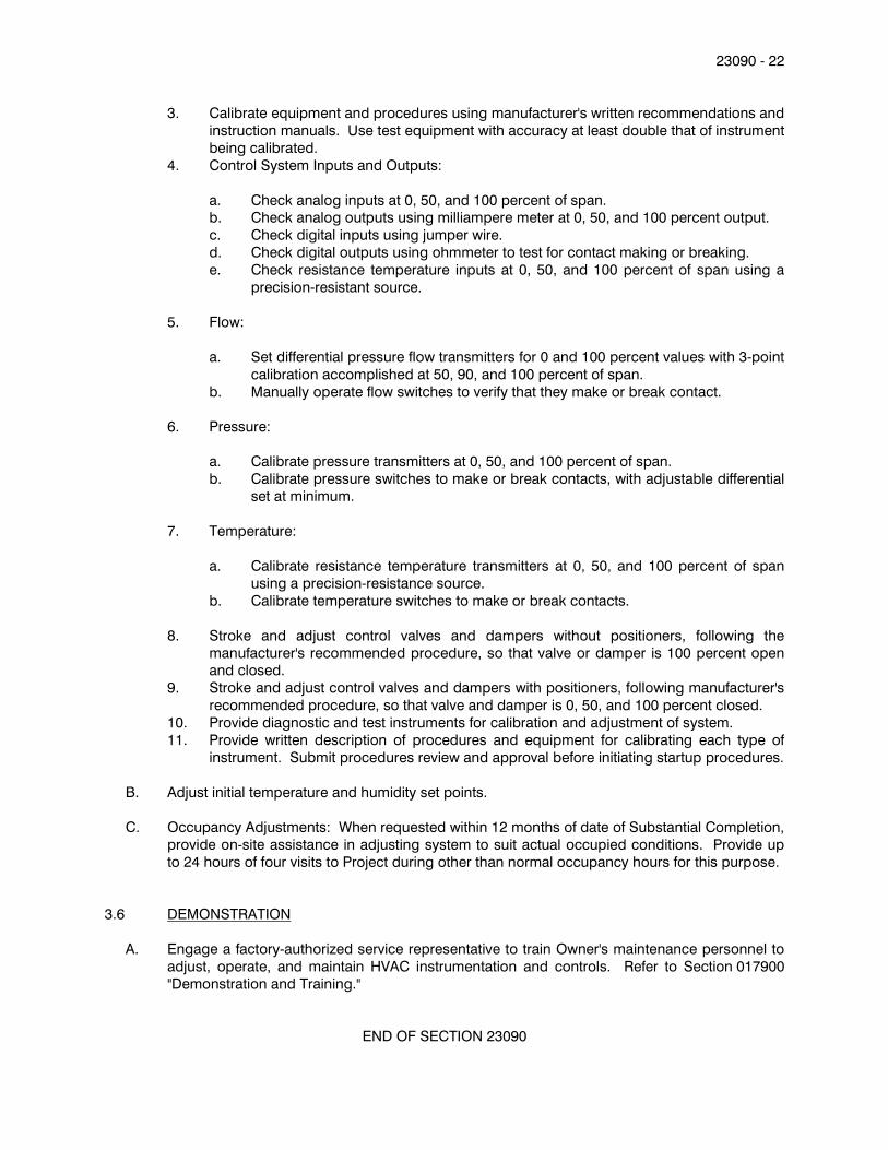
23090 - 22
3. Calibrate equipment and procedures using manufacturer's written recommendations and
instruction manuals. Use test equipment with accuracy at least double that of instrument
being calibrated.
4. Control System Inputs and Outputs:
a. Check analog inputs at 0, 50, and 100 percent of span. b. Check analog outputs using milliampere meter at 0, 50, and 100 percent output.
c. Check digital inputs using jumper wire.
d. Check digital outputs using ohmmeter to test for contact making or breaking.
e. Check resistance temperature inputs at 0, 50, and 100 percent of span using a
precision-resistant source.
5. Flow:
a. Set differential pressure flow transmitters for 0 and 100 percent values with 3-point
calibration accomplished at 50, 90, and 100 percent of span.
b. Manually operate flow switches to verify that they make or break contact.
6. Pressure:
a. Calibrate pressure transmitters at 0, 50, and 100 percent of span.
b. Calibrate pressure switches to make or break contacts, with adjustable differential
set at minimum.
7. Temperature:
a. Calibrate resistance temperature transmitters at 0, 50, and 100 percent of span
using a precision-resistance source.
b. Calibrate temperature switches to make or break contacts.
8. Stroke and adjust control valves and dampers without positioners, following the
manufacturer's recommended procedure, so that valve or damper is 100 percent open and closed.
9. Stroke and adjust control valves and dampers with positioners, following manufacturer's
recommended procedure, so that valve and damper is 0, 50, and 100 percent closed.
10. Provide diagnostic and test instruments for calibration and adjustment of system.
11. Provide written description of procedures and equipment for calibrating each type of
instrument. Submit procedures review and approval before initiating startup procedures.
B. Adjust initial temperature and humidity set points.
C. Occupancy Adjustments: When requested within 12 months of date of Substantial Completion,
provide on-site assistance in adjusting system to suit actual occupied conditions. Provide up
to 24 hours of four visits to Project during other than normal occupancy hours for this purpose.
3.6 DEMONSTRATION
A. Engage a factory-authorized service representative to train Owner's maintenance personnel to
adjust, operate, and maintain HVAC instrumentation and controls. Refer to Section 017900
"Demonstration and Training."
END OF SECTION 23090
23093 - 1
SECTION 23093 - SEQUENCE OF OPERATIONS FOR HVAC CONTROLS
PART 1 - GENERAL
1.1 RELATED DOCUMENTS
A. Drawings and general provisions of Contract, including General and Supplementary Conditions
and Division 1 Specification sections.
B. Division 23 Section "Common Work Results for HVAC".
C. Division 23 Section "Facility Management Systems".
1.2 DESCRIPTION OF WORK
A. Sequence of operation is hereby defined as the manner and method by which controls
function. Requirements for each type of control system operation are specified in this section.
B. Operating equipment, devices, and system components required for control systems are
specified in Division 23 Section "Facility Management Systems".
C. HVAC Systems shall be controlled with a Direct Digital Control (DDC) system, sometimes
referred to as a Facility Management System (FMS), according to the point list contained at the
end of this section. Additional hardware, input/output points or software programming not
specifically identified in the point list but which are required to meet the following sequences of
operation shall be provided.
D. All electrical Controllers, Relays, Transducers, etc., required for stand-alone control shall be
housed in a NEMA 1 enclosure with a lockable door.
1.3 DEFINITIONS
A. FMS: Facility management system
B. DAT: Discharge air temperature.
C. VSD: Variable speed drive.
D. DX: Direct expansion.
PART 2 - PRODUCTS (Not Applicable)
PART 3 - EXECUTION
3.1 ALARMS
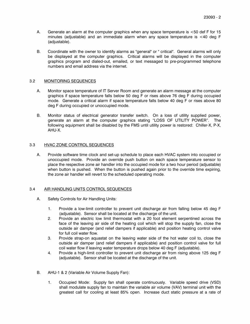
23093 - 2
A. Generate an alarm at the computer graphics when any space temperature is <50 def F for 15
minutes (adjustable) and an immediate alarm when any space temperature is <40 deg F
(adjustable).
B. Coordinate with the owner to identify alarms as "general" or " critical". General alarms will only
be displayed at the computer graphics. Critical alarms will be displayed in the computer
graphics program and dialed-out, emailed, or text messaged to pre-programmed telephone
numbers and email address via the internet.
3.2 MONITORING SEQUENCES
A. Monitor space temperature of IT Server Room and generate an alarm message at the computer
graphics if space temperature falls below 50 deg F or rises above 76 deg F during occupied
mode. Generate a critical alarm if space temperature falls below 40 deg F or rises above 80
deg F during occupied or unoccupied mode.
B. Monitor status of electrical generator transfer switch. On a loss of utility supplied power,
generate an alarm at the computer graphics stating “LOSS OF UTILITY POWER”. The
following equipment shall be disabled by the FMS until utility power is restored: Chiller-X, P-X,
AHU-X.
3.3 HVAC ZONE CONTROL SEQUENCES
A. Provide software time clock and set-up schedule to place each HVAC system into occupied or
unoccupied mode. Provide an override push button on each space temperature sensor to
place the respective zone air handler into the occupied mode for a two hour period (adjustable)
when button is pushed. When the button is pushed again prior to the override time expiring,
the zone air handler will revert to the scheduled operating mode.
3.4 AIR HANDLING UNITS CONTROL SEQUENCES
A. Safety Controls for Air Handling Units:
1. Provide a low-limit controller to prevent unit discharge air from falling below 45 deg F
(adjustable). Sensor shall be located at the discharge of the unit.
2. Provide an electric low limit thermostat with a 20 foot element serpentined across the
face of the leaving air side of the heating coil which will stop the supply fan, close the
outside air damper (and relief dampers if applicable) and position heating control valve
for full coil water flow.
3. Provide strap-on aquastat on the leaving water side of the hot water coil to, close the
outside air damper (and relief dampers if applicable) and position control valve for full
coil water flow if leaving water temperature drops below 40 deg F (adjustable).
4. Provide a high-limit controller to prevent unit discharge air from rising above 125 deg F
(adjustable). Sensor shall be located at the discharge of the unit.
B. AHU-1 & 2 (Variable Air Volume Supply Fan):
1. Occupied Mode: Supply fan shall operate continuously. Variable speed drive (VSD)
shall modulate supply fan to maintain the variable air volume (VAV) terminal unit with the
greatest call for cooling at least 85% open. Increase duct static pressure at a rate of

23093 - 3
0.25” every 10 minutes (adjustable) until any VAV terminal unit exceeding 95% open,
closes down to 85% open. Duct static pressure shall be determined by pressure sensors
located 2/3 down the longest duct run or as shown on the drawings. A high limit
discharge pressure sensor, located at the fan discharge, shall prevent the supply fan
from generating a discharge pressure greater than 6.5” w.c. (adjustable).
The outside air damper shall be opened to provide minimum outside air. Minimum
outside air volume shall be maintained by modulating outside air damper and return air
damper as required to maintain a constant differential pressure between the outside air
duct (pickup point located immediately upstream of the outside air damper) and
outdoors. If outside air dry bulb temperature is less than space and cooling is required,
modulate outside air damper open to provide outside air economizer cooling. A mixed
air temperature controller shall maintain a minimum DAT of 55 deg F.
Modulate the hot water coil control valve and stages of DX cooling as required to
maintain DAT set point. Reset DAT to maximum possible temperature to satisfy zone
with the greatest call for cooling. Minimum DAT shall be 42 deg F (adjustable).
If any space or return duct humidistat is not satisfied, reset the DAT to minimum set point
until all relative humidity’s are 2% below set point. DAT shall be set to minimum level
and zone VAV terminal unit shall provide reheat as required to maintain space
temperature set point.
2. Unoccupied Mode: Close outside air damper, cycle unit supply fan with full hot water
flow to maintain reduced set point temperature. If space humidity exceeds set point, the
unit shall be placed into occupied mode until space humidity is 5% RH below set point.
3. Morning Warm-Up: Dependent on space and ambient conditions, the FMS shall
determine optimum start time to return zones temperature to their occupied set points 5
to 10 minutes prior to occupied schedule. The outside air damper shall close and the
return air damper shall open to its maximum position, hot water coil control valve shall
modulate to maintain a maximum 125 deg F (adjustable) discharge air temperature, VAV
terminals primary air valve shall open to full flow. As a zone reaches occupied heating
set point, VAV terminal primary air valve and reheat valve shall modulate to prevent zone
over heating. This cycle shall continue until all zones have reached their occupied
heating set point temperature.
4. Morning Cool-Down: Dependent on space and ambient conditions, the FMS shall
determine optimum start time to return zones temperature to their occupied cooling set
points 5 to 10 minutes prior to occupied schedule. The outside air damper shall close
and the return damper shall open to its maximum position with stages of DX cooling to
maintain a discharge air temperature of 50 deg F, VAV terminal units shall operate as
under normal occupied mode. This cycle shall continue until all zones have reached
their occupied cooling set point temperature.
3.5 EXHAUST FAN CONTROL SEQUENCE
A. EF-4: Continuous operation.
B. EF-1 & 2: Operate during occupied cycle of AHU-1, off otherwise.
C. EF-3: Operate during occupied cycle of AHU-2, off otherwise.
D. EF-5: Operate with a piloted wall switch.

23093 - 4
3.6 SINGLE DUCT SHUT OFF VAV TERMINAL UNIT WITH HOT WATER REHEAT
A. Occupied Mode: Modulate open primary air valve with a rise in space temperature. With a fall
in space temperature, modulate primary air valve towards the minimum setting. With a
continued fall in space temperature below the heating set point, modulate open the hot water
coil control valve, when valve is 100% open, modulate air valve increasing air flow to maintain
space heating set point. If hot water is not available, close primary air valve 100% with a fall in
space temperature below heating set point. If the associated occupancy sensor indicates no
occupants, the VAV box is to revert to unoccupied temperature setpoints.
B. Unoccupied Mode: Open primary air valve, close hot water coil control valve. If the associated
occupancy sensor indicates occupants, the VAV box and associated air handler are to revert to
occupied mode.
C. Refer to sheet E2.0 for occupancy sensors indicated to control associated VAV boxes.
D. Morning Warm-Up/Cool-Down & Night Purge: Refer to respective HVAC unit sequence of
operation. During morning warm-up, provide maximum primary air with full hot water coil flow
until space occupied heating set point is reached at which time reset primary air valve to
heating air flow and modulate control valve to maintain set point.
3.7 PUMP CONTROL SEQUENCE
A. Boiler Pump (Boiler Primary Hot Water Loop): Cycle with their respective boilers. On a failure
to establish flow within 15 seconds after a call to operate, generate an alarm message reading
“PRIMARY HOT WATER PUMP FAILURE” to be automatically displayed in computer graphics
and dial out, text messaged, and email to pre-programmed addresses and/or numbers. Pump
shall continue to operate for a period of 30 seconds following shut down of associated boiler
burner.
B. P-1 & P-2 (Building Secondary Hot Water Distribution Loop): Variable volume pumping.
Energize lead variable volume pump on a call for hot water. Modulate lead pump with a 4-20
mA output to the variable speed drive (VSD) to maintain a 10 PSIG (adjustable) differential
pressure across the supply and return mains at location(s) shown. With a failure of the lead
pump to establish flow within 15 seconds after a call to operate, start the lag pump and
generate an alarm message reading "SECONDARY BUILDING HOT WATER DISTRIBUTION
LOOP LEAD PUMP FAILURE" to be automatically displayed in computer graphics and dial out,
text messaged, and email to pre-programmed addresses and/or numbers.
C. HWRP-1 (Domestic Hot Water Recirculation Pump): Pump is to be controlled by an aquastat
and enabled during occupied mode by the FMS.
3.8 BOILER AND HEATING WATER CONTROL SEQUENCE
A. On a call for hot water the FMS shall energize the hot water distribution pump(s), and
packaged controls shall be enabled to maintain the hot water loop temperature. The packaged
controls shall activate and stage boilers and their associated pumps as required to maintain the
loop supply temperature. The boiler controller shall sequence the boilers and modulate output
such that total system efficiency is maximized. The packaged controller shall reset the supply
water temperature to satisfy the zone with the greatest heating demand. The packaged
controller shall have a set of dry contacts to notify the FMS of any alarm state within the boiler
plant or controller.
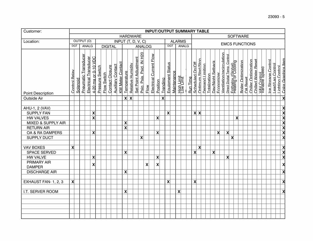
23093 - 5
Customer:
INPUT/OUTPUT SUMMARY TABLE
HARDWARE SOFTWARE
Location:
OUTPUT (O) INPUT (T, D, V, C) ALARMS EMCS FUNCTIONS
DGT ANALG DIGITAL ANALOG DGT ANALG
Point Description Co
ntr
ol R
ela
y
So
len
oid
Pn
eu
matic T
ran
sd
ucer
Ele
ctr
ical T
ran
sd
ucer
4-2
0 m
a o
r 0
-10
VD
C
Pre
ssu
re S
witch
Flo
w S
witch
Co
nta
ct
Clo
su
re
Au
xili
ary
Co
nta
ct
KW
Mete
r C
on
tact
Tem
pera
ture
Rela
tive H
um
idity
Set
Po
int
Ad
justm
en
t
Psig
, P
sia
, P
sid
, IN
H2
0
Flo
w
Ele
ctr
ical C
urr
en
t F
low
Po
sitio
n
Tre
nd
ing
Eq
uip
men
t S
tatu
s
Main
ten
an
ce
Hig
h L
imit
Lo
w L
imit
(Tem
pera
ture
) R
un
Tim
e
Sch
ed
ule
d O
n/O
ff
Op
tim
um
Sta
rt/S
top
D
em
an
d L
imitin
g
To
taliz
atio
n
Day/N
igh
t S
etb
ack
Eco
no
miz
er
Ven
tila
tio
n/r
ecir
cu
latio
n
Dir
ect
Dig
ital T
em
p C
on
tro
l
En
thalp
y (
Glo
bal)
H
eatin
g o
r C
oo
ling
Reset
Bo
iler
Op
tim
izatio
n
OA
Reset
Ch
iller
Op
tim
izatio
n
Ch
illed
Wate
r R
eset
VA
V C
on
tro
l V
ari
ab
le S
peed
Pu
mp
ing
Ic
e S
tora
ge C
on
tro
l Lead
/Lag
Co
ntr
ol
Lig
htin
g C
on
tro
l C
olo
r G
rap
hic
s Ite
m
Outside Air X X X X
AHU-1, 2 (VAV) X
SUPPLY FAN X X X X X
HW VALVES X X X X
MIXED & SUPPLY AIR X X
RETURN AIR X X
OA & RA DAMPERS X X X X X
SUPPLY DUCT X X X
VAV BOXES X X X
SPACE SERVED X X X X
HW VALVE X X X X
PRIMARY AIR
DAMPER X X X X
DISCHARGE AIR X X
EXHAUST FAN- 1, 2, 3 X X X X
I.T. SERVER ROOM X X X
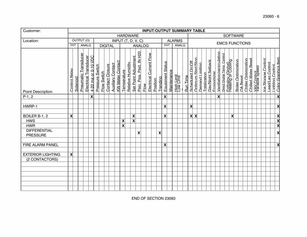
23093 - 6
Customer:
INPUT/OUTPUT SUMMARY TABLE
HARDWARE SOFTWARE
Location:
OUTPUT (O) INPUT (T, D, V, C) ALARMS EMCS FUNCTIONS
DGT ANALG DIGITAL ANALOG DGT ANALG
Point Description Co
ntr
ol R
ela
y
So
len
oid
Pn
eu
matic T
ran
sd
ucer
Ele
ctr
ical T
ran
sd
ucer
4-2
0 m
a o
r 0
-10
VD
C
Pre
ssu
re S
witch
Flo
w S
witch
Co
nta
ct
Clo
su
re
Au
xili
ary
Co
nta
ct
KW
Mete
r C
on
tact
Tem
pera
ture
Rela
tive H
um
idity
Set
Po
int
Ad
justm
en
t
Psig
, P
sia
, P
sid
, IN
H2
0
Flo
w
Ele
ctr
ical C
urr
en
t F
low
Po
sitio
n
Tre
nd
ing
Eq
uip
men
t S
tatu
s
Main
ten
an
ce
Hig
h L
imit
Lo
w L
imit
(Tem
pera
ture
) R
un
Tim
e
Sch
ed
ule
d O
n/O
ff
Op
tim
um
Sta
rt/S
top
D
em
an
d L
imitin
g
To
taliz
atio
n
Day/N
igh
t S
etb
ack
Eco
no
miz
er
Ven
tila
tio
n/r
ecir
cu
latio
n
Dir
ect
Dig
ital T
em
p C
on
tro
l
En
thalp
y (
Glo
bal)
H
eatin
g o
r C
oo
ling
Reset
Bo
iler
Op
tim
izatio
n
OA
Reset
Ch
iller
Op
tim
izatio
n
Ch
illed
Wate
r R
eset
VA
V C
on
tro
l V
ari
ab
le S
peed
Pu
mp
ing
Ic
e S
tora
ge C
on
tro
l Lead
/Lag
Co
ntr
ol
Lig
htin
g C
on
tro
l C
olo
r G
rap
hic
s Ite
m
P-1, 2 X X X X
HWRP-1 X X X
BOILER B-1, 2 X X X X X X X
HWS X X X
HWR X X
DIFFERENTIAL
PRESSURE X X X
FIRE ALARM PANEL X X
EXTERIOR LIGHTING X
(2 CONTACTORS)
END OF SECTION 23093

23123 - 1
SECTION 23123 - FACILITY NATURAL-GAS PIPING
PART 1 - GENERAL
1.1 RELATED DOCUMENTS
A. Drawings and general provisions of the Contract, including General and Supplementary
Conditions and Division 01 Specification Sections, apply to this Section.
1.2 SUMMARY
A. Section Includes:
1. Pipes, tubes, and fittings.
2. Piping specialties.
3. Piping and tubing joining materials.
4. Valves.
5. Pressure regulators.
6. Service meters.
7. Concrete bases.
1.3 DEFINITIONS
A. Finished Spaces: Spaces other than mechanical and electrical equipment rooms, furred
spaces, pipe and duct shafts, unheated spaces immediately below roof, spaces above ceilings,
unexcavated spaces, crawlspaces, and tunnels.
B. Exposed, Interior Installations: Exposed to view indoors. Examples include finished occupied
spaces and mechanical equipment rooms.
C. Exposed, Exterior Installations: Exposed to view outdoors or subject to outdoor ambient
temperatures and weather conditions. Examples include rooftop locations.
1.4 PERFORMANCE REQUIREMENTS
A. Minimum Operating-Pressure Ratings:
1. Piping and Valves: 100 psig minimum unless otherwise indicated.
2. Service Regulators: 65 psig 100 psig minimum unless otherwise indicated.
B. Natural-Gas System Pressures within Buildings: Two pressure ranges. Primary pressure is
more than 0.5 psig but not more than 2 psig, and is reduced to secondary pressure of 0.5 psig
or less.
1.5 ACTION SUBMITTALS
A. Product Data: For each type of the following:
23123 - 2
1. Piping specialties.
2. Corrugated, stainless-steel tubing with associated components.
3. Valves. Include pressure rating, capacity, settings, and electrical connection data of
selected models.
4. Pressure regulators. Indicate pressure ratings and capacities. 5. Dielectric fittings.
1.6 INFORMATIONAL SUBMITTALS
A. Coordination Drawings: Plans and details, drawn to scale, on which natural-gas piping is
shown and coordinated with other installations, using input from installers of the items
involved.
B. Welding certificates.
C. Field quality-control reports.
1.7 QUALITY ASSURANCE
A. Steel Support Welding Qualifications: Qualify procedures and personnel according to
AWS D1.1/D1.1M, "Structural Welding Code - Steel."
B. Pipe Welding Qualifications: Qualify procedures and operators according to ASME Boiler and
Pressure Vessel Code.
C. Electrical Components, Devices, and Accessories: Listed and labeled as defined in NFPA 70,
by a qualified testing agency, and marked for intended location and application.
1.8 DELIVERY, STORAGE, AND HANDLING
A. Handling Flammable Liquids: Remove and dispose of liquids from existing natural-gas piping
according to requirements of authorities having jurisdiction.
B. Deliver pipes and tubes with factory-applied end caps. Maintain end caps through shipping,
storage, and handling to prevent pipe end damage and to prevent entrance of dirt, debris, and moisture.
C. Store and handle pipes and tubes having factory-applied protective coatings to avoid
damaging coating, and protect from direct sunlight.
D. Protect stored PE pipes and valves from direct sunlight.
1.9 PROJECT CONDITIONS
A. Interruption of Existing Natural-Gas Service: Do not interrupt natural-gas service to facilities
occupied by Owner or others unless permitted under the following conditions and then only
after arranging to provide purging and startup of natural-gas supply according to requirements
indicated:
23123 - 3
1. Notify Owner no fewer than two days in advance of proposed interruption of natural-gas
service.
2. Do not proceed with interruption of natural-gas service without Owner's written
permission.
1.10 COORDINATION
A. Coordinate sizes and locations of concrete bases with actual equipment provided.
B. Coordinate requirements for access panels and doors for valves installed concealed behind
finished surfaces. Comply with requirements in Division 08 "Access Doors and Frames."
PART 2 - PRODUCTS
2.1 PIPES, TUBES, AND FITTINGS
A. Steel Pipe: ASTM A 53/A 53M, black steel, Schedule 40, Type E or S, Grade B.
1. Malleable-Iron Threaded Fittings: ASME B16.3, Class 150, standard pattern.
2. Wrought-Steel Welding Fittings: ASTM A 234/A 234M for butt welding and socket
welding.
3. Unions: ASME B16.39, Class 150, malleable iron with brass-to-iron seat, ground joint, and threaded ends.
4. Forged-Steel Flanges and Flanged Fittings: ASME B16.5, minimum Class 150, including
bolts, nuts, and gaskets of the following material group, end connections, and facings:
a. Material Group: 1.1.
b. End Connections: Threaded or butt welding to match pipe.
c. Lapped Face: Not permitted underground.
d. Gasket Materials: ASME B16.20, metallic, flat, asbestos free, aluminum o-rings,
and spiral-wound metal gaskets.
e. Bolts and Nuts: ASME B18.2.1, carbon steel aboveground and stainless steel underground.
5. Protective Coating for Underground Piping: Factory-applied, three-layer coating of
epoxy, adhesive, and PE.
a. Joint Cover Kits: Epoxy paint, adhesive, and heat-shrink PE sleeves.
6. Mechanical Couplings:
a. Manufacturers: Subject to compliance with requirements, provide products by
one of the following:
1) Dresser Piping Specialties; Division of Dresser, Inc.
2) Smith-Blair, Inc.
b. Stainless-steel flanges and tube with epoxy finish. c. Buna-nitrile seals.
d. Stainless-steel bolts, washers, and nuts.
23123 - 4
e. Coupling shall be capable of joining PE pipe to PE pipe, steel pipe to PE pipe, or
steel pipe to steel pipe.
f. Steel body couplings installed underground on plastic pipe shall be factory
equipped with anode.
2.2 PIPING SPECIALTIES
A. Appliance Flexible Connectors:
1. Indoor, Fixed-Appliance Flexible Connectors: Comply with ANSI Z21.24.
2. Indoor, Movable-Appliance Flexible Connectors: Comply with ANSI Z21.69.
3. Outdoor, Appliance Flexible Connectors: Comply with ANSI Z21.75.
4. Corrugated stainless-steel tubing with polymer coating.
5. Operating-Pressure Rating: 0.5 psig.
6. End Fittings: Zinc-coated steel.
7. Threaded Ends: Comply with ASME B1.20.1.
8. Maximum Length: 72 inches
B. Quick-Disconnect Devices: Comply with ANSI Z21.41.
1. Copper-alloy convenience outlet and matching plug connector.
2. Nitrile seals.
3. Hand operated with automatic shutoff when disconnected.
4. For indoor or outdoor applications.
5. Adjustable, retractable restraining cable.
C. Weatherproof Vent Cap: Cast- or malleable-iron increaser fitting with corrosion-resistant wire
screen, with free area at least equal to cross-sectional area of connecting pipe and threaded-
end connection.
2.3 JOINING MATERIALS
A. Joint Compound and Tape: Suitable for natural gas.
B. Welding Filler Metals: Comply with AWS D10.12/D10.12M for welding materials appropriate for
wall thickness and chemical analysis of steel pipe being welded.
C. Brazing Filler Metals: Alloy with melting point greater than 1000 deg F complying with
AWS A5.8/A5.8M. Brazing alloys containing more than 0.05 percent phosphorus are
prohibited.
2.4 MANUAL GAS SHUTOFF VALVES
A. See "Underground Manual Gas Shutoff Valve Schedule" and "Aboveground Manual Gas
Shutoff Valve Schedule" Articles for where each valve type is applied in various services.
B. General Requirements for Metallic Valves, NPS 2 and Smaller: Comply with ASME B16.33.
1. CWP Rating: 125 psig.
2. Threaded Ends: Comply with ASME B1.20.1.
3. Dryseal Threads on Flare Ends: Comply with ASME B1.20.3.
23123 - 5
4. Tamperproof Feature: Locking feature for valves indicated in "Underground Manual Gas
Shutoff Valve Schedule" and "Aboveground Manual Gas Shutoff Valve Schedule"
Articles.
5. Listing: Listed and labeled by an NRTL acceptable to authorities having jurisdiction for
valves 1 inch and smaller. 6. Service Mark: Valves 1-1/4 inches to NPS 2 shall have initials "WOG" permanently
marked on valve body.
C. General Requirements for Metallic Valves, NPS 2-1/2 and Larger: Comply with ASME B16.38.
1. CWP Rating: 125 psig.
2. Flanged Ends: Comply with ASME B16.5 for steel flanges.
3. Tamperproof Feature: Locking feature for valves indicated in "Underground Manual Gas
Shutoff Valve Schedule" and "Aboveground Manual Gas Shutoff Valve Schedule"
Articles.
4. Service Mark: Initials "WOG" shall be permanently marked on valve body.
D. Two-Piece, Full-Port, Bronze Ball Valves with Bronze Trim: MSS SP-110.
1. Manufacturers: Subject to compliance with requirements, provide products by one of
the following:
a. BrassCraft Manufacturing Company; a Masco company.
b. Conbraco Industries, Inc.; Apollo Div.
c. Lyall, R. W. & Company, Inc.
d. McDonald, A. Y. Mfg. Co.
e. Perfection Corporation; a subsidiary of American Meter Company.
2. Body: Bronze, complying with ASTM B 584.
3. Ball: Chrome-plated bronze. 4. Stem: Bronze; blowout proof.
5. Seats: Reinforced TFE; blowout proof.
6. Packing: Threaded-body packnut design with adjustable-stem packing.
7. Ends: Threaded, flared, or socket as indicated in "Underground Manual Gas Shutoff
Valve Schedule" and "Aboveground Manual Gas Shutoff Valve Schedule" Articles.
8. CWP Rating: 600 psig.
9. Listing: Valves NPS 1 and smaller shall be listed and labeled by an NRTL acceptable to
authorities having jurisdiction.
10. Service: Suitable for natural-gas service with "WOG" indicated on valve body.
E. Cast-Iron, Nonlubricated Plug Valves: MSS SP-78.
1. Manufacturers: Subject to compliance with requirements, provide products by one of
the following:
a. McDonald, A. Y. Mfg. Co.
b. Mueller Co.; Gas Products Div.
c. Xomox Corporation; a Crane company.
2. Body: Cast iron, complying with ASTM A 126, Class B.
3. Plug: Bronze or nickel-plated cast iron.
4. Seat: Coated with thermoplastic. 5. Stem Seal: Compatible with natural gas.
23123 - 6
6. Ends: Threaded or flanged as indicated in "Underground Manual Gas Shutoff Valve
Schedule" and "Aboveground Manual Gas Shutoff Valve Schedule" Articles.
7. Operator: Square head or lug type with tamperproof feature where indicated.
8. Pressure Class: 125 psig.
9. Listing: Valves NPS 1 and smaller shall be listed and labeled by an NRTL acceptable to authorities having jurisdiction.
10. Service: Suitable for natural-gas service with "WOG" indicated on valve body.
2.5 PRESSURE REGULATORS
A. General Requirements:
1. Single stage and suitable for natural gas.
2. Steel jacket and corrosion-resistant components.
3. Elevation compensator.
4. End Connections: Threaded for regulators NPS 2 and smaller; flanged for regulators
NPS 2-1/2 and larger.
B. Line Pressure Regulators: Comply with ANSI Z21.80.
1. Manufacturers: Subject to compliance with requirements, provide products by one of
the following:
a. Actaris.
b. American Meter Company.
c. Eclipse Combustion, Inc.
d. Fisher Control Valves and Regulators; Division of Emerson Process Management.
e. Invensys.
f. Maxitrol Company.
g. Richards Industries; Jordan Valve Div.
2. Body and Diaphragm Case: Cast iron or die-cast aluminum.
3. Springs: Zinc-plated steel; interchangeable.
4. Diaphragm Plate: Zinc-plated steel.
5. Seat Disc: Nitrile rubber resistant to gas impurities, abrasion, and deformation at the
valve port.
6. Orifice: Aluminum; interchangeable.
7. Seal Plug: Ultraviolet-stabilized, mineral-filled nylon.
8. Single-port, self-contained regulator with orifice no larger than required at maximum
pressure inlet, and no pressure sensing piping external to the regulator.
9. Pressure regulator shall maintain discharge pressure setting downstream, and not exceed 150 percent of design discharge pressure at shutoff.
10. Overpressure Protection Device: Factory mounted on pressure regulator.
11. Atmospheric Vent: Factory- or field-installed, stainless-steel screen in opening if not
connected to vent piping.
C. Appliance Pressure Regulators: Comply with ANSI Z21.18.
1. Manufacturers: Subject to compliance with requirements, provide products by one of
the following:
a. Canadian Meter Company Inc.
b. Eaton Corporation; Controls Div.
23123 - 7
c. Harper Wyman Co.
d. Maxitrol Company.
e. SCP, Inc.
2. Body and Diaphragm Case: Die-cast aluminum.
3. Springs: Zinc-plated steel; interchangeable. 4. Diaphragm Plate: Zinc-plated steel.
5. Seat Disc: Nitrile rubber.
6. Seal Plug: Ultraviolet-stabilized, mineral-filled nylon.
7. Factory-Applied Finish: Minimum three-layer polyester and polyurethane paint finish.
8. Regulator may include vent limiting device, instead of vent connection, if approved by
authorities having jurisdiction.
9. Maximum Inlet Pressure: 6 inch w.c.
2.6 DIELECTRIC FITTINGS
A. General Requirements: Assembly of copper alloy and ferrous materials with separating
nonconductive insulating material. Include end connections compatible with pipes to be joined.
B. Dielectric Unions:
1. Manufacturers: Subject to compliance with requirements, provide products by one of
the following:
a. Capitol Manufacturing Company.
b. Central Plastics Company.
c. Hart Industries International, Inc.
d. Jomar International Ltd.
e. Matco-Norca, Inc. f. McDonald, A. Y. Mfg. Co.
g. Watts Regulator Co.; a division of Watts Water Technologies, Inc.
h. Wilkins; a Zurn company.
2. Description:
a. Standard: ASSE 1079.
b. Pressure Rating: 125 psig minimum at 180 deg F.
c. End Connections: Solder-joint copper alloy and threaded ferrous.
C. Dielectric Flanges:
1. Manufacturers: Subject to compliance with requirements, provide products by one of the following:
a. Capitol Manufacturing Company.
b. Central Plastics Company.
c. Matco-Norca, Inc.
d. Watts Regulator Co.; a division of Watts Water Technologies, Inc.
e. Wilkins; a Zurn company.
2. Description:
23123 - 8
a. Standard: ASSE 1079.
b. Factory-fabricated, bolted, companion-flange assembly.
c. Pressure Rating: 125 psig minimum at 180 deg F.
d. End Connections: Solder-joint copper alloy and threaded ferrous; threaded
solder-joint copper alloy and threaded ferrous.
D. Dielectric-Flange Insulating Kits:
1. Manufacturers: Subject to compliance with requirements, provide products by one of
the following:
a. Advance Products & Systems, Inc.
b. Calpico, Inc.
c. Central Plastics Company.
d. Pipeline Seal and Insulator, Inc.
2. Description:
a. Nonconducting materials for field assembly of companion flanges.
b. Pressure Rating: 150 psig. c. Gasket: Neoprene or phenolic.
d. Bolt Sleeves: Phenolic or polyethylene.
e. Washers: Phenolic with steel backing washers.
2.7 LABELING AND IDENTIFYING
A. Detectable Warning Tape: Acid- and alkali-resistant, PE film warning tape manufactured for
marking and identifying underground utilities, a minimum of 6 inches wide and 4 mils thick,
continuously inscribed with a description of utility, with metallic core encased in a protective
jacket for corrosion protection, detectable by metal detector when tape is buried up to 30
inches deep; colored yellow.
PART 3 - EXECUTION
3.1 EXAMINATION
A. Examine roughing-in for natural-gas piping system to verify actual locations of piping
connections before equipment installation.
B. Proceed with installation only after unsatisfactory conditions have been corrected.
3.2 PREPARATION
A. Close equipment shutoff valves before turning off natural gas to premises or piping section.
B. Inspect natural-gas piping according to NFPA 54 and the International Fuel Gas Code to
determine that natural-gas utilization devices are turned off in piping section affected.
C. Comply with NFPA 54 and the International Fuel Gas Code requirements for prevention of accidental ignition.
23123 - 9
3.3 OUTDOOR PIPING INSTALLATION
A. Comply with NFPA 54 and the International Fuel Gas Code for installation and purging of
natural-gas piping.
B. Install underground, natural-gas piping buried at least 36 inches below finished grade. Comply
with requirements in Division 02 "Earth Moving" for excavating, trenching, and backfilling.
1. If natural-gas piping is installed less than 36 inches below finished grade, install it in
containment conduit.
C. Install underground, PE, natural-gas piping according to ASTM D 2774.
D. Steel Piping with Protective Coating:
1. Apply joint cover kits to pipe after joining to cover, seal, and protect joints.
2. Repair damage to PE coating on pipe as recommended in writing by protective coating
manufacturer.
3. Replace pipe having damaged PE coating with new pipe.
E. Install pressure gage downstream from each service regulator. Pressure gages are specified in
Division 23 "Meters and Gages for HVAC Piping."
3.4 INDOOR PIPING INSTALLATION
A. Comply with NFPA 54 and the International Fuel Gas Code for installation and purging of
natural-gas piping.
B. Drawing plans, schematics, and diagrams indicate general location and arrangement of piping
systems. Indicated locations and arrangements are used to size pipe and calculate friction
loss, expansion, and other design considerations. Install piping as indicated unless deviations
to layout are approved on Coordination Drawings.
C. Arrange for pipe spaces, chases, slots, sleeves, and openings in building structure during
progress of construction, to allow for mechanical installations.
D. Install piping in concealed locations unless otherwise indicated and except in equipment
rooms and service areas.
E. Install piping indicated to be exposed and piping in equipment rooms and service areas at
right angles or parallel to building walls. Diagonal runs are prohibited unless specifically
indicated otherwise.
F. Install piping above accessible ceilings to allow sufficient space for ceiling panel removal.
G. Locate valves for easy access.
H. Install natural-gas piping at uniform grade of 2 percent down toward drip and sediment traps.
I. Install piping free of sags and bends.
J. Install fittings for changes in direction and branch connections.
23123 - 10
K. Verify final equipment locations for roughing-in.
L. Comply with requirements in Sections specifying gas-fired appliances and equipment for
roughing-in requirements.
M. Drips and Sediment Traps: Install drips at points where condensate may collect, including
service-meter outlets. Locate where accessible to permit cleaning and emptying. Do not install where condensate is subject to freezing.
1. Construct drips and sediment traps using tee fitting with bottom outlet plugged or
capped. Use nipple a minimum length of 3 pipe diameters, but not less than 3 inches
long and same size as connected pipe. Install with space below bottom of drip to
remove plug or cap.
N. Extend relief vent connections for service regulators, line regulators, and overpressure
protection devices to outdoors and terminate with weatherproof vent cap.
O. Conceal pipe installations in walls, pipe spaces, utility spaces, above ceilings, below grade or
floors, and in floor channels unless indicated to be exposed to view.
P. Concealed Location Installations: Except as specified below, install concealed natural-gas piping and piping installed under the building in containment conduit constructed of steel pipe
with welded joints as described in Part 2. Install a vent pipe from containment conduit to
outdoors and terminate with weatherproof vent cap.
1. Above Accessible Ceilings: Natural-gas piping, fittings, valves, and regulators may be
installed in accessible spaces without containment conduit.
2. In Walls or Partitions: Protect tubing installed inside partitions or hollow walls from
physical damage using steel striker barriers at rigid supports.
a. Exception: Tubing passing through partitions or walls does not require striker
barriers.
3. Prohibited Locations:
a. Do not install natural-gas piping in or through circulating air ducts, clothes or trash
chutes, chimneys or gas vents (flues), ventilating ducts, or dumbwaiter or elevator
shafts.
b. Do not install natural-gas piping in solid walls or partitions.
Q. Use eccentric reducer fittings to make reductions in pipe sizes. Install fittings with level side
down.
R. Connect branch piping from top or side of horizontal piping.
S. Install unions in pipes NPS 2 and smaller, adjacent to each valve, at final connection to each
piece of equipment. Unions are not required at flanged connections.
T. Do not use natural-gas piping as grounding electrode.
U. Install strainer on inlet of each line-pressure regulator and automatic or electrically operated
valve.
23123 - 11
V. Install pressure gage downstream from each line regulator. Pressure gages are specified in
Division 23 "Meters and Gages for HVAC Piping."
W. Install sleeves for piping penetrations of walls, ceilings, and floors. Comply with requirements
for sleeves specified in Division 23 "Sleeves and Sleeve Seals for HVAC Piping."
X. Install sleeve seals for piping penetrations of concrete walls and slabs. Comply with requirements for sleeve seals specified in Division 23 "Sleeves and Sleeve Seals for HVAC
Piping."
Y. Install escutcheons for piping penetrations of walls, ceilings, and floors. Comply with
requirements for escutcheons specified in Division 23 "Escutcheons for HVAC Piping."
3.5 VALVE INSTALLATION
A. Install manual gas shutoff valve for each gas appliance ahead of corrugated stainless-steel
tubing, aluminum, or copper connector.
B. Install underground valves with valve boxes.
C. Install regulators and overpressure protection devices with maintenance access space
adequate for servicing and testing.
D. Install anode for metallic valves in underground PE piping.
3.6 PIPING JOINT CONSTRUCTION
A. Ream ends of pipes and tubes and remove burrs.
B. Remove scale, slag, dirt, and debris from inside and outside of pipe and fittings before
assembly.
C. Threaded Joints:
1. Thread pipe with tapered pipe threads complying with ASME B1.20.1.
2. Cut threads full and clean using sharp dies.
3. Ream threaded pipe ends to remove burrs and restore full inside diameter of pipe. 4. Apply appropriate tape or thread compound to external pipe threads unless dryseal
threading is specified.
5. Damaged Threads: Do not use pipe or pipe fittings with threads that are corroded or
damaged. Do not use pipe sections that have cracked or open welds.
D. Welded Joints:
1. Construct joints according to AWS D10.12/D10.12M, using qualified processes and
welding operators.
2. Bevel plain ends of steel pipe.
3. Patch factory-applied protective coating as recommended by manufacturer at field welds
and where damage to coating occurs during construction.
E. Brazed Joints: Construct joints according to AWS's "Brazing Handbook," "Pipe and Tube"
Chapter.
23123 - 12
F. Flanged Joints: Install gasket material, size, type, and thickness appropriate for natural-gas
service. Install gasket concentrically positioned.
G. Flared Joints: Cut tubing with roll cutting tool. Flare tube end with tool to result in flare
dimensions complying with SAE J513. Tighten finger tight, then use wrench. Do not
overtighten.
H. PE Piping Heat-Fusion Joints: Clean and dry joining surfaces by wiping with clean cloth or
paper towels. Join according to ASTM D 2657.
1. Plain-End Pipe and Fittings: Use butt fusion.
2. Plain-End Pipe and Socket Fittings: Use socket fusion.
3.7 HANGER AND SUPPORT INSTALLATION
A. Comply with requirements for pipe hangers and supports specified in Division 23 "Hangers and
Supports for HVAC Piping and Equipment."
B. Install hangers for horizontal steel piping with the following maximum spacing and minimum
rod sizes:
1. NPS 1 and Smaller: Maximum span, 96 inches; minimum rod size, 3/8 inch. 2. NPS 1-1/4: Maximum span, 108 inches; minimum rod size, 3/8 inch.
3. NPS 1-1/2 and NPS 2: Maximum span, 108 inches; minimum rod size, 3/8 inch.
4. NPS 2-1/2 to NPS 3-1/2: Maximum span, 10 feet; minimum rod size, 1/2 inch.
5. NPS 4 and Larger: Maximum span, 10 feet; minimum rod size, 5/8 inch.
C. Install hangers for horizontal drawn-temper copper tubing with the following maximum spacing
and minimum rod sizes:
1. NPS 3/8: Maximum span, 48 inches; minimum rod size, 3/8 inch.
2. NPS 1/2 and NPS 5/8: Maximum span, 72 inches; minimum rod size, 3/8 inch.
3. NPS 3/4 and NPS 7/8: Maximum span, 84 inches; minimum rod size, 3/8 inch. 4. NPS 1: Maximum span, 96 inches; minimum rod size, 3/8 inch.
D. Install hangers for horizontal, corrugated stainless-steel tubing with the following maximum
spacing and minimum rod sizes:
1. NPS 3/8: Maximum span, 48 inches; minimum rod size, 3/8 inch.
2. NPS 1/2: Maximum span, 72 inches; minimum rod size, 3/8 inch.
3. NPS 3/4 and Larger: Maximum span, 96 inches; minimum rod size, 3/8 inch.
3.8 CONNECTIONS
A. Connect to utility's gas main according to utility's procedures and requirements.
B. Install natural-gas piping electrically continuous, and bonded to gas appliance equipment grounding conductor of the circuit powering the appliance according to NFPA 70.
C. Install piping adjacent to appliances to allow service and maintenance of appliances.

23123 - 13
D. Connect piping to appliances using manual gas shutoff valves and unions. Install valve within
72 inches of each gas-fired appliance and equipment. Install union between valve and
appliances or equipment.
E. Sediment Traps: Install tee fitting with capped nipple in bottom to form drip, as close as
practical to inlet of each appliance.
3.9 LABELING AND IDENTIFYING
A. Comply with requirements in Division 23 "Identification for HVAC Piping and Equipment" for
piping and valve identification.
B. Install detectable warning tape directly above gas piping, 12 inches below finished grade,
except 6 inches below subgrade under pavements and slabs.
3.10 PAINTING
A. Comply with requirements in Division 09 "Exterior Painting" and "Interior Painting" for painting
interior and exterior natural-gas piping.
B. Paint exposed, exterior metal piping, valves, service regulators, service meters and meter bars,
earthquake valves, and piping specialties, except components, with factory-applied paint or protective coating.
1. Alkyd System: MPI EXT 5.1D.
a. Prime Coat: Alkyd anticorrosive metal primer.
b. Intermediate Coat: Exterior alkyd enamel matching topcoat.
c. Topcoat: Exterior alkyd enamel (semigloss).
d. Color: Gray.
C. Damage and Touchup: Repair marred and damaged factory-applied finishes with materials
and by procedures to match original factory finish.
3.11 FIELD QUALITY CONTROL
A. Perform tests and inspections.
B. Tests and Inspections:
1. Test, inspect, and purge natural gas according to NFPA 54 and the International Fuel
Gas Code and authorities having jurisdiction.
C. Natural-gas piping will be considered defective if it does not pass tests and inspections.
D. Prepare test and inspection reports.
3.12 OUTDOOR PIPING SCHEDULE
A. Underground natural-gas piping shall be one of the following:

23123 - 14
1. PE pipe and fittings joined by heat fusion, or mechanical couplings; service-line risers
with tracer wire terminated in an accessible location.
2. Steel pipe with wrought-steel fittings and welded joints, or mechanical couplings. Coat
pipe and fittings with protective coating for steel piping.
B. Aboveground natural-gas piping shall be one of the following:
1. Steel pipe with malleable-iron fittings and threaded joints.
2. Steel pipe with wrought-steel fittings and welded joints.
C. Containment Conduit: Steel pipe with wrought-steel fittings and welded joints. Coat pipe and
fittings with protective coating for steel piping.
3.13 INDOOR PIPING SCHEDULE FOR SYSTEM PRESSURES LESS THAN 0.5 PSIG
A. Aboveground, branch piping NPS 1 and smaller shall be the following:
1. Steel pipe with malleable-iron fittings and threaded joints.
B. Aboveground, distribution piping shall be one of the following:
1. Steel pipe with malleable-iron fittings and threaded joints.
2. Steel pipe with wrought-steel fittings and welded joints.
3.14 INDOOR PIPING SCHEDULE FOR SYSTEM PRESSURES MORE THAN 0.5 PSIG AND LESS
THAN 5 PSIG
A. Aboveground, branch piping NPS 1 and smaller shall be the following:
1. Steel pipe with malleable-iron fittings and threaded joints.
B. Aboveground, distribution piping shall be one of the following:
1. Steel pipe with malleable-iron fittings and threaded joints.
2. Steel pipe with steel welding fittings and welded joints.
3.15 ABOVEGROUND MANUAL GAS SHUTOFF VALVE SCHEDULE
A. Valves for pipe sizes NPS 2 and smaller at service meter shall be the following:
1. Two-piece, full-port, bronze ball valves with bronze trim.
B. Valves for pipe sizes NPS 2-1/2 and larger at service meter shall be one of the following:
1. Two-piece, full-port, bronze ball valves with bronze trim.
2. Bronze plug valve.
C. Distribution piping valves for pipe sizes NPS 2 and smaller shall be the following:
1. Two-piece, full-port, bronze ball valves with bronze trim.
23123 - 15
D. Distribution piping valves for pipe sizes NPS 2-1/2 and larger shall be the following:
1. Two-piece, full-port, bronze ball valves with bronze trim.
E. Valves in branch piping for single appliance shall be the following:
1. Two-piece, full-port, bronze ball valves with bronze trim.
END OF SECTION 23123

23211 - 1
SECTION 23211 - HYDRONIC PIPING
PART 1 - GENERAL
1.1 SUMMARY
A. Section includes pipe and fitting materials and joining methods for the following:
1. Hot-water heating piping. 2. Makeup-water piping.
3. Condensate-drain piping.
4. Air-vent piping.
5. Locations of and details for penetration and firestopping for fire- and smoke-rated wall
and floor and ceiling assemblies.
1.2 INFORMATIONAL SUBMITTALS
A. Field quality-control reports.
1.3 QUALITY ASSURANCE
A. ASME Compliance: Comply with ASME B31.9, "Building Services Piping," for materials,
products, and installation.
PART 2 - PRODUCTS
2.1 PERFORMANCE REQUIREMENTS
A. Hydronic piping components and installation shall be capable of withstanding the following
minimum working pressure and temperature unless otherwise indicated:
1. Hot-Water Heating Piping: 100 psig at 200 deg F.
2. Makeup-Water Piping: 80 psig at 150 deg F.
3. Condensate-Drain Piping: 150 deg F.
4. Air-Vent Piping: 200 deg F.
2.2 COPPER TUBE AND FITTINGS
A. Drawn-Temper Copper Tubing: ASTM B 88, Type L.
B. DWV Copper Tubing: ASTM B 306, Type DWV.
C. Grooved, Mechanical-Joint, Wrought-Copper Fittings: ASME B16.22.
1. Manufacturers: Subject to compliance with requirements, provide products by one of
the following:

23211 - 2
a. Anvil International, Inc.
b. Star Pipe Products.
c. Victaulic Company.
2. Grooved-End Copper Fittings: ASTM B 75, copper tube or ASTM B 584, bronze casting.
3. Grooved-End-Tube Couplings: Rigid pattern unless otherwise indicated; gasketed fitting. Ductile-iron housing with keys matching pipe and fitting grooves, EPDM gasket
rated for minimum 230 deg F for use with housing, and steel bolts and nuts.
D. Wrought-Copper Unions: ASME B16.22.
2.3 STEEL PIPE AND FITTINGS
A. Steel Pipe: ASTM A 53/A 53M, black steel with plain ends; welded and seamless, Grade B,
and wall thickness as indicated in "Piping Applications" Article.
B. Cast-Iron Threaded Fittings: ASME B16.4; Classes 125 and 250 as indicated in "Piping
Applications" Article.
C. Malleable-Iron Threaded Fittings: ASME B16.3, Classes 150 and 300 as indicated in "Piping
Applications" Article.
D. Malleable-Iron Unions: ASME B16.39; Classes 150, 250, and 300 as indicated in "Piping
Applications" Article.
E. Cast-Iron Pipe Flanges and Flanged Fittings: ASME B16.1, Classes 25, 125, and 250; raised
ground face, and bolt holes spot faced as indicated in "Piping Applications" Article.
F. Wrought Cast- and Forged-Steel Flanges and Flanged Fittings: ASME B16.5, including bolts,
nuts, and gaskets of the following material group, end connections, and facings:
1. Material Group: 1.1.
2. End Connections: Butt welding.
3. Facings: Raised face.
G. Grooved Mechanical-Joint Fittings and Couplings:
1. Manufacturers: Subject to compliance with requirements, provide products by one of
the following:
a. Anvil International, Inc.
b. Central Sprinkler Company.
c. Star Pipe Products.
d. Victaulic Company.
2. Joint Fittings: ASTM A 536, Grade 65-45-12 ductile iron; ASTM A 47/A 47M,
Grade 32510 malleable iron; ASTM A 53/A 53M, Type F, E, or S, Grade B fabricated
steel; or ASTM A 106/A 106M, Grade B steel fittings with grooves or shoulders constructed to accept grooved-end couplings; with nuts, bolts, locking pin, locking
toggle, or lugs to secure grooved pipe and fittings.
3. Couplings: Ductile- or malleable-iron housing and EPDM or nitrile gasket of central
cavity pressure-responsive design; with nuts, bolts, locking pin, locking toggle, or lugs to
secure grooved pipe and fittings.
23211 - 3
2.4 JOINING MATERIALS
A. Pipe-Flange Gasket Materials: Suitable for chemical and thermal conditions of piping system
contents.
1. ASME B16.21, nonmetallic, flat, asbestos free, 1/8-inch maximum thickness unless
otherwise indicated.
a. Full-Face Type: For flat-face, Class 125, cast-iron and cast-bronze flanges.
b. Narrow-Face Type: For raised-face, Class 250, cast-iron and steel flanges.
B. Flange Bolts and Nuts: ASME B18.2.1, carbon steel, unless otherwise indicated.
C. Solder Filler Metals: ASTM B 32, lead-free alloys. Include water-flushable flux according to
ASTM B 813.
D. Brazing Filler Metals: AWS A5.8/A5.8M, BCuP Series, copper-phosphorus alloys for joining
copper with copper; or BAg-1, silver alloy for joining copper with bronze or steel.
E. Welding Filler Metals: Comply with AWS D10.12M/D10.12 for welding materials appropriate for
wall thickness and chemical analysis of steel pipe being welded.
F. Gasket Material: Thickness, material, and type suitable for fluid to be handled and working temperatures and pressures.
2.5 TRANSITION FITTINGS
A. Plastic-to-Metal Transition Fittings:
1. Manufacturers: Subject to compliance with requirements, provide products by one of
the following:
a. Charlotte Pipe and Foundry Company.
b. IPEX Inc.
c. KBI (King Bros. Industries).
2. One-piece fitting with one threaded brass or copper insert and one solvent-cement-joint end of material and wall thickness to match plastic pipe material.
B. Plastic-to-Metal Transition Unions:
1. Manufacturers: Subject to compliance with requirements, provide products by one of
the following:
a. Charlotte Pipe and Foundry Company.
b. IPEX Inc.
c. KBI (King Bros. Industries).
d. NIBCO INC; Model #T/S-1710.
2. Brass or copper end, solvent-cement-joint end of material and wall thickness to match
plastic pipe material, rubber gasket, and threaded union.
23211 - 4
2.6 DIELECTRIC FITTINGS
A. General Requirements: Assembly of copper alloy and ferrous materials with separating
nonconductive insulating material. Include end connections compatible with pipes to be
joined.
B. Dielectric Unions:
1. Manufacturers: Subject to compliance with requirements, provide products by one of
the following:
a. A.Y. McDonald Mfg. Co.
b. Capitol Manufacturing Company.
c. Central Plastics Company.
d. Hart Industries International, Inc.
e. Jomar International, Ltd.
f. Matco-Norca.
g. Watts Regulator Co.
h. Zurn Industries, LLC; AquaSpec Commercial Faucet Products.
2. Description:
a. Standard: ASSE 1079.
b. Pressure Rating: 125 psig minimum at 180 deg F.
c. End Connections: Solder-joint copper alloy and threaded ferrous.
2.7 BYPASS CHEMICAL FEEDER
A. Description: Welded steel construction; 125-psig working pressure; 5-gal. capacity; with fill
funnel and inlet, outlet, and drain valves.
1. Chemicals: Specially formulated, based on analysis of makeup water, to prevent
accumulation of scale and corrosion in piping and connected equipment.
PART 3 - EXECUTION
3.1 PIPING APPLICATIONS
A. Hot-water heating piping, aboveground, NPS 2 and smaller, shall be any of the following:
1. Type L, drawn-temper copper tubing, wrought-copper fittings, and soldered or pressure-
seal joints.
2. Schedule 40, Grade B, Type 96 steel pipe; Class 125, cast-iron fittings; cast-iron flanges
and flange fittings; and threaded joints.
B. Hot-water heating piping, aboveground, NPS 2-1/2 and larger, shall be any of the following:
1. Type L, drawn-temper copper tubing, wrought-copper fittings, and soldered joints.
2. Schedule 40 steel pipe; grooved, mechanical joint coupling and fittings; and grooved, mechanical joints.
23211 - 5
C. Hot-Water Heating Piping Installed Belowground and within Slabs:Type K, annealed-temper
copper tubing, wrought-copper fittings, and brazed joints. Use the fewest possible joints.
D. Air-Vent Piping:
1. Inlet: Same as service where installed with metal-to-plastic transition fittings for plastic
piping systems according to piping manufacturer's written instructions. 2. Outlet: Type K, annealed-temper copper tubing with soldered or flared joints.
3.2 PIPING INSTALLATIONS
A. Drawing plans, schematics, and diagrams indicate general location and arrangement of piping
systems. Install piping as indicated unless deviations to layout are approved on Coordination
Drawings.
B. Install piping in concealed locations unless otherwise indicated and except in equipment
rooms and service areas.
C. Install piping indicated to be exposed and piping in equipment rooms and service areas at
right angles or parallel to building walls. Diagonal runs are prohibited unless specifically
indicated otherwise.
D. Install piping above accessible ceilings to allow sufficient space for ceiling panel removal.
E. Install piping to permit valve servicing.
F. Install piping at indicated slopes.
G. Install piping free of sags and bends.
H. Install fittings for changes in direction and branch connections.
I. Install piping to allow application of insulation.
J. Select system components with pressure rating equal to or greater than system operating
pressure.
K. Install groups of pipes parallel to each other, spaced to permit applying insulation and servicing of valves.
L. Install drains, consisting of a tee fitting, NPS 3/4 ball valve, and short NPS 3/4 threaded nipple
with cap, at low points in piping system mains and elsewhere as required for system drainage.
M. Install piping at a uniform grade of 0.2 percent upward in direction of flow.
N. Reduce pipe sizes using eccentric reducer fitting installed with level side up.
O. Install branch connections to mains using tee fittings in main pipe, with the branch connected
to the bottom of the main pipe. For up-feed risers, connect the branch to the top of the main
pipe.
P. Install valves according to Division 23 "General-Duty Valves for HVAC Piping."

23211 - 6
Q. Install unions in piping, NPS 2 and smaller, adjacent to valves, at final connections of
equipment, and elsewhere as indicated.
R. Install flanges in piping, NPS 2-1/2 and larger, at final connections of equipment and elsewhere
as indicated.
S. Install shutoff valve immediately upstream of each dielectric fitting.
T. Comply with requirements in Division 23 "Identification for HVAC Piping and Equipment" for
identifying piping.
U. Install sleeves for piping penetrations of walls, ceilings, and floors. Comply with requirements
for sleeves specified in Division 23 "Sleeves and Sleeve Seals for HVAC Piping."
V. Install sleeve seals for piping penetrations of concrete walls and slabs. Comply with
requirements for sleeve seals specified in Division 23 "Sleeves and Sleeve Seals for HVAC
Piping."
W. Install escutcheons for piping penetrations of walls, ceilings, and floors. Comply with
requirements for escutcheons specified in Division 23 "Escutcheons for HVAC Piping."
3.3 DIELECTRIC FITTING INSTALLATION
A. Install dielectric fittings in piping at connections of dissimilar metal piping and tubing.
B. Dielectric Fittings for NPS 2 and Smaller: Use dielectric nipples or unions.
C. Dielectric Fittings for NPS 2-1/2 to NPS 4: Use dielectric flanges or nipples.
D. Dielectric Fittings for NPS 5 and Larger: Use dielectric flange kits.
3.4 HANGERS AND SUPPORTS
A. Comply with requirements in Section 230529 "Hangers and Supports for HVAC Piping and
Equipment" for hanger, support, and anchor devices. Comply with the following requirements
for maximum spacing of supports.
B. Install the following pipe attachments:
1. Adjustable steel clevis hangers for individual horizontal piping less than 20 feet long.
2. Adjustable roller hangers and spring hangers for individual horizontal piping 20 feet or
longer.
3. Pipe Roller: MSS SP-58, Type 44 for multiple horizontal piping 20 feet or longer,
supported on a trapeze.
4. Spring hangers to support vertical runs.
5. Provide copper-clad hangers and supports for hangers and supports in direct contact
with copper pipe.
C. Install hangers for steel piping with the following maximum spacing and minimum rod sizes:
1. NPS 3/4: Maximum span, 7 feet. 2. NPS 1: Maximum span, 7 feet.

23211 - 7
3. NPS 1-1/2: Maximum span, 9 feet.
4. NPS 2: Maximum span, 10 feet.
5. NPS 2-1/2: Maximum span, 11 feet.
6. NPS 3 and Larger: Maximum span, 12 feet.
D. Install hangers for drawn-temper copper piping with the following maximum spacing and minimum rod sizes:
1. NPS 3/4: Maximum span, 5 feet; minimum rod size, 1/4 inch.
2. NPS 1: Maximum span, 6 feet; minimum rod size, 1/4 inch.
3. NPS 1-1/4Maximum span, 7 feet; minimum rod size, 3/8 inch.
4. NPS 1-1/2: Maximum span, 8 feet; minimum rod size, 3/8 inch.
5. NPS 2: Maximum span, 8 feet; minimum rod size, 3/8 inch.
6. NPS 2-1/2: Maximum span, 9 feet; minimum rod size, 3/8 inch.
7. NPS 3 and Larger: Maximum span, 10 feet; minimum rod size, 3/8 inch.
E. Support vertical runs at roof, at each floor, and at 10-foot intervals between floors.
3.5 PIPE JOINT CONSTRUCTION
A. Ream ends of pipes and tubes and remove burrs. Bevel plain ends of steel pipe.
B. Remove scale, slag, dirt, and debris from inside and outside of pipe and fittings before
assembly.
C. Soldered Joints: Apply ASTM B 813, water-flushable flux, unless otherwise indicated, to tube
end. Construct joints according to ASTM B 828 or CDA's "Copper Tube Handbook," using
lead-free solder alloy complying with ASTM B 32.
D. Brazed Joints: Construct joints according to AWS's "Brazing Handbook," "Pipe and Tube"
Chapter, using copper-phosphorus brazing filler metal complying with AWS A5.8/A5.8M.
E. Threaded Joints: Thread pipe with tapered pipe threads according to ASME B1.20.1. Cut threads full and clean using sharp dies. Ream threaded pipe ends to remove burrs and restore
full ID. Join pipe fittings and valves as follows:
1. Apply appropriate tape or thread compound to external pipe threads unless dry seal
threading is specified.
2. Damaged Threads: Do not use pipe or pipe fittings with threads that are corroded or
damaged. Do not use pipe sections that have cracked or open welds.
F. Flanged Joints: Select appropriate gasket material, size, type, and thickness for service
application. Install gasket concentrically positioned. Use suitable lubricants on bolt threads.
G. Grooved Joints: Assemble joints with coupling and gasket, lubricant, and bolts. Cut or roll
grooves in ends of pipe based on pipe and coupling manufacturer's written instructions for pipe wall thickness. Use grooved-end fittings and rigid, grooved-end-pipe couplings.
3.6 TERMINAL EQUIPMENT CONNECTIONS
A. Sizes for supply and return piping connections shall be the same as or larger than equipment
connections.
23211 - 8
B. Install control valves in accessible locations close to connected equipment.
C. Install ports for pressure gages and thermometers at coil inlet and outlet connections. Comply
with requirements in Section 230519 "Meters and Gages for HVAC Piping."
3.7 CHEMICAL TREATMENT
A. Fill system with fresh water and add liquid alkaline compound with emulsifying agents and detergents to remove grease and petroleum products from piping. Circulate solution for a
minimum of 24 hours, drain, clean strainer screens, and refill with fresh water.
B. Add initial chemical treatment and maintain water quality in ranges noted above for the first
year of operation.
3.8 FIELD QUALITY CONTROL
A. Prepare hydronic piping according to ASME B31.9 and as follows:
1. Leave joints, including welds, uninsulated and exposed for examination during test.
2. Provide temporary restraints for expansion joints that cannot sustain reactions due to
test pressure. If temporary restraints are impractical, isolate expansion joints from
testing. 3. Flush hydronic piping systems with clean water; then remove and clean or replace
strainer screens.
4. Isolate equipment from piping. If a valve is used to isolate equipment, its closure shall
be capable of sealing against test pressure without damage to valve. Install blinds in
flanged joints to isolate equipment.
5. Install safety valve, set at a pressure no more than one-third higher than test pressure, to
protect against damage by expanding liquid or other source of overpressure during test.
B. Perform the following tests on hydronic piping:
1. Use ambient temperature water as a testing medium unless there is risk of damage due
to freezing. Another liquid that is safe for workers and compatible with piping may be
used.
2. While filling system, use vents installed at high points of system to release air. Use
drains installed at low points for complete draining of test liquid.
3. Isolate expansion tanks and determine that hydronic system is full of water.
4. Subject piping system to hydrostatic test pressure that is not less than 1.5 times the system's working pressure. Test pressure shall not exceed maximum pressure for any
vessel, pump, valve, or other component in system under test. Verify that stress due to
pressure at bottom of vertical runs does not exceed 90 percent of specified minimum
yield strength or 1.7 times the "SE" value in Appendix A in ASME B31.9, "Building
Services Piping."
5. After hydrostatic test pressure has been applied for at least 10 minutes, examine piping,
joints, and connections for leakage. Eliminate leaks by tightening, repairing, or
replacing components, and repeat hydrostatic test until there are no leaks.
6. Prepare written report of testing.
23211 - 9
C. Perform the following before operating the system:
1. Open manual valves fully.
2. Inspect pumps for proper rotation.
3. Set makeup pressure-reducing valves for required system pressure.
4. Inspect air vents at high points of system and determine if all are installed and operating freely (automatic type), or bleed air completely (manual type).
5. Set temperature controls so all coils are calling for full flow.
6. Inspect and set operating temperatures of hydronic equipment, such as boilers, chillers,
cooling towers, to specified values.
7. Verify lubrication of motors and bearings.
END OF SECTION 23211

23212 - 1
SECTION 23212 - HYDRONIC PUMPS
PART 1 - GENERAL
1.1 RELATED DOCUMENTS
A. Drawings and general provisions of the Contract, including General and Supplementary
Conditions and Division 01 Specification Sections, apply to this Section.
1.2 SUMMARY
A. Section Includes:
1. Close-coupled, in-line centrifugal pumps.
1.3 DEFINITIONS
A. Buna-N: Nitrile rubber.
B. EPT: Ethylene propylene terpolymer.
1.4 ACTION SUBMITTALS
A. Product Data: For each type of pump. Include certified performance curves and rated
capacities, operating characteristics, furnished specialties, final impeller dimensions, and
accessories for each type of product indicated. Indicate pump's operating point on curves.
B. Shop Drawings: For each pump.
1. Show pump layout and connections.
2. Include setting drawings with templates for installing foundation and anchor bolts and
other anchorages.
3. Include diagrams for power, signal, and control wiring.
1.5 CLOSEOUT SUBMITTALS
A. Operation and Maintenance Data: For pumps to include in emergency, operation, and
maintenance manuals.
PART 2 - PRODUCTS
2.1 CLOSE-COUPLED, IN-LINE CENTRIFUGAL PUMPS
A. Manufacturers: Subject to compliance with requirements, provide products by one of the
following:

23212 - 2
1. Armstrong Pumps Inc.
2. ITT Corporation; Bell & Gossett.
B. Description: Factory-assembled and -tested, centrifugal, overhung-impeller, close-coupled, in-
line pump as defined in HI 1.1-1.2 and HI 1.3; designed for installation with pump and motor
shafts mounted horizontally or vertically.
C. Pump Construction:
1. Casing: Radially split, cast iron, with threaded gage tappings at inlet and
outlet, replaceable bronze wear rings, and threaded companion-flange or union end
connections.
2. Impeller: ASTM B 584, cast bronze; statically and dynamically balanced, keyed to shaft,
and secured with a locking cap screw. For constant-speed pumps, trim impeller to
match specified performance.
3. Pump Shaft: Steel, with copper-alloy shaft sleeve.
4. Seal: Mechanical seal consisting of carbon rotating ring against a ceramic seat held by
a stainless-steel spring, and Buna-N or EPT bellows and gasket. Include water slinger on shaft between motor and seal.
5. Pump Bearings: Permanently lubricated ball bearings.
D. Motor: Single speed and rigidly mounted to pump casing.
1. Electrical Components, Devices, and Accessories: Listed and labeled as defined in
NFPA 70, by a qualified testing agency, and marked for intended location and
application.
2. Comply with NEMA designation, temperature rating, service factor, and efficiency
requirements for motors specified in Section 230513 "Common Motor Requirements for
HVAC Equipment."
2.2 PUMP SPECIALTY FITTINGS
A. Suction Diffuser:
1. Angle pattern.
2. 175-psig pressure rating, cast-iron body and end cap, pump-inlet fitting.
3. Bronze startup and bronze or stainless-steel permanent strainers.
4. Bronze or stainless-steel straightening vanes.
5. Drain plug.
6. Factory-fabricated support.
B. Triple-Duty Valve:
1. Angle or straight pattern. 2. 175-psig pressure rating, cast-iron body, pump-discharge fitting.
3. Drain plug and bronze-fitted shutoff, balancing, and check valve features.
4. Brass gage ports with integral check valve and orifice for flow measurement.
23212 - 3
PART 3 - EXECUTION
3.1 EXAMINATION
A. Examine equipment foundations and anchor-bolt locations for compliance with requirements
for installation tolerances and other conditions affecting performance of the Work.
B. Examine roughing-in for piping systems to verify actual locations of piping connections before pump installation.
C. Examine foundations and inertia bases for suitable conditions where pumps are to be installed.
D. Proceed with installation only after unsatisfactory conditions have been corrected.
3.2 PUMP INSTALLATION
A. Comply with HI 1.4.
B. Install pumps to provide access for periodic maintenance including removing motors,
impellers, couplings, and accessories.
C. Independently support pumps and piping so weight of piping is not supported by pumps and
weight of pumps is not supported by piping.
D. Equipment Mounting:
1. Comply with requirements for vibration isolation devices specified in Section 230548.13
"Vibration Controls for HVAC."
3.3 ALIGNMENT
A. Engage a factory-authorized service representative to perform alignment service.
B. Comply with requirements in Hydronics Institute standards for alignment of pump and motor
shaft. Add shims to the motor feet and bolt motor to base frame. Do not use grout between
motor feet and base frame.
C. Comply with pump and coupling manufacturers' written instructions.
D. After alignment is correct, tighten foundation bolts evenly but not too firmly. Completely fill
baseplate with nonshrink, nonmetallic grout while metal blocks and shims or wedges are in
place. After grout has cured, fully tighten foundation bolts.
3.4 CONNECTIONS
A. Where installing piping adjacent to pump, allow space for service and maintenance.
B. Connect piping to pumps. Install valves that are same size as piping connected to pumps.
23212 - 4
C. Install suction and discharge pipe sizes equal to or greater than diameter of pump nozzles.
D. Install check, shutoff, and throttling valves or triple duty valve with additional shutoff valve on
discharge side of pumps.
E. Install Y-type strainer and shutoff valve on suction side of pumps.
F. Install flexible connectors on suction and discharge sides of base-mounted pumps between pump casing and valves.
G. Install pressure gages on pump suction and discharge or at integral pressure-gage tapping, or
install single gage with multiple-input selector valve.
H. Install check valve and gate or ball valve on each condensate pump unit discharge.
I. Ground equipment according to Section 260526 "Grounding and Bonding for Electrical
Systems."
J. Connect wiring according to Section 260519 "Low-Voltage Electrical Power Conductors and
Cables."
3.5 STARTUP SERVICE
A. Engage a factory-authorized service representative to perform startup service.
1. Complete installation and startup checks according to manufacturer's written
instructions.
2. Check piping connections for tightness.
3. Clean strainers on suction piping.
4. Perform the following startup checks for each pump before starting:
a. Verify bearing lubrication.
b. Verify that pump is free to rotate by hand and that pump for handling hot liquid is
free to rotate with pump hot and cold. If pump is bound or drags, do not operate
until cause of trouble is determined and corrected. c. Verify that pump is rotating in the correct direction.
5. Prime pump by opening suction valves and closing drains, and prepare pump for
operation.
6. Start motor.
7. Open discharge valve slowly.
3.6 DEMONSTRATION
A. Engage a factory-authorized service representative to train Owner's maintenance personnel to
adjust, operate, and maintain hydronic pumps.
END OF SECTION 23212
23216 - 1
SECTION 23216 - HYDRONIC PIPING SPECIALTIES
PART 1 - GENERAL
1.1 SUMMARY
A. Section includes special-duty valves and specialties for the following:
1. Hot-water heating piping. 2. Makeup-water piping.
3. Condensate-drain piping.
4. Air-vent piping.
1.2 ACTION SUBMITTALS
A. Product Data: For each type of the following:
1. Valves: Include flow and pressure drop curves based on manufacturer's testing for
calibrated-orifice balancing valves and automatic flow-control valves.
2. Air-control devices.
3. Hydronic specialties.
1.3 CLOSEOUT SUBMITTALS
A. Operation and maintenance data.
1.4 QUALITY ASSURANCE
A. ASME Compliance: Safety valves and pressure vessels shall bear the appropriate ASME label.
Fabricate and stamp air separators and expansion tanks to comply with ASME Boiler and
Pressure Vessel Code: Section VIII, Division 1.
PART 2 - PRODUCTS
2.1 PERFORMANCE REQUIREMENTS
A. Hydronic piping components and installation shall be capable of withstanding the following
minimum working pressure and temperature unless otherwise indicated:
1. Hot-Water Heating Piping: 100 psig at 200 deg F (93 deg C).
2. Makeup-Water Piping: 80 psig (552 kPa) at 150 deg F (66 deg C).
3. Condensate-Drain Piping: 150 deg F (66 deg C).
4. Air-Vent Piping: 200 deg F (93 deg C).
23216 - 2
2.2 VALVES
A. Gate, Globe, Check, Ball, and Butterfly Valves: Comply with requirements specified in Division
23 "General-Duty Valves for HVAC Piping.
B. Automatic Temperature-Control Valves, Actuators, and Sensors: Comply with requirements
specified in Division "Instrumentation and Control for HVAC.
C. Plastic Ball Valves:
1. Manufacturers: Subject to compliance with requirements, provide products by one of
the following:
a. American Valve, Inc.
b. Asahi/America.
c. Charlotte Pipe and Foundry Company.
d. Colonial Engineering.
e. George Fischer Inc.
f. Hayward Industrial Products, Inc.
g. IPEX Inc. h. Jomar International, Ltd.
i. KBI (King Bros. Industries).
j. Legend Valve.
k. NIBCO INC.
l. Plast-O-Matic Valves, Inc.
m. SMC The Specialty Mfg. Co.
n. Thermoplastic Valves Inc.
o. Watts Regulator Co.
2. Body: One-, two-, or three-piece CPVC or PVC to match piping. 3. Ball: Full-port CPVC or PVC to match piping.
4. Seats: PTFE.
5. Seals: EPDM.
6. End Connections: Socket, union, or flanged.
7. Handle Style: Tee shape.
8. CWP Rating: Equal to piping service.
9. Maximum Operating Temperature: Equal to piping service.
10. Comply with MSS SP-122.
D. Bronze, Calibrated-Orifice, Balancing Valves:
1. Manufacturers: Subject to compliance with requirements, provide products by one of the following:
a. Armstrong Pumps, Inc.
b. Bell & Gossett Domestic Pump.
c. Flow Design Inc.
d. Gerand Engineering Co.
e. Griswold Controls.
f. Nexus Valve, Inc.
g. Taco.
h. Tour & Andersson; available through Victaulic Company.
2. Body: Bronze, ball or plug type with calibrated orifice or venturi.
23216 - 3
3. Ball: Brass or stainless steel.
4. Plug: Resin.
5. Seat: PTFE.
6. End Connections: Threaded or socket.
7. Pressure Gage Connections: Integral seals for portable differential pressure meter. 8. Handle Style: Lever, with memory stop to retain set position.
9. CWP Rating: Minimum 125 psig (860 kPa).
10. Maximum Operating Temperature: 250 deg F (121 deg C).
E. Diaphragm-Operated, Pressure-Reducing Valves: ASME labeled.
1. Manufacturers: Subject to compliance with requirements, provide products by one of
the following:
a. AMTROL, Inc.
b. Armstrong Pumps, Inc.
c. Bell & Gossett Domestic Pump.
d. Conbraco Industries, Inc. e. Spence Engineering Company, Inc.
f. Watts Regulator Co.
2. Body: Bronze or brass.
3. Disc: Glass and carbon-filled PTFE.
4. Seat: Brass.
5. Stem Seals: EPDM O-rings.
6. Diaphragm: EPT.
7. Low inlet-pressure check valve.
8. Inlet Strainer: removable without system shutdown. 9. Valve Seat and Stem: Noncorrosive.
10. Valve Size, Capacity, and Operating Pressure: Selected to suit system in which
installed, with operating pressure and capacity factory set and field adjustable.
F. Automatic Flow-Control Valves:
1. Manufacturers: Subject to compliance with requirements, provide products by one of
the following:
a. Flow Design Inc.
b. Griswold Controls.
c. Nexus Valve, Inc.
2. Body: Brass or ferrous metal. 3. Piston and Spring Assembly: Stainless steel, tamper proof, self-cleaning, and
removable.
4. Combination Assemblies: Include bonze or brass-alloy ball valve.
5. Identification Tag: Marked with zone identification, valve number, and flow rate.
6. Size: Same as pipe in which installed.
7. Performance: Maintain constant flow, plus or minus 5 percent over system pressure
fluctuations.
8. Minimum CWP Rating: 175 psig (1207 kPa).
9. Maximum Operating Temperature: 200 deg F (93 deg C).
23216 - 4
2.3 AIR-CONTROL DEVICES
A. Manual Air Vents:
1. Manufacturers: Subject to compliance with requirements, provide products by one of
the following:
a. AMTROL, Inc. b. Armstrong Pumps, Inc.
c. Bell & Gossett Domestic Pump.
d. Nexus Valve, Inc.
e. Taco, Inc.
2. Body: Bronze.
3. Internal Parts: Nonferrous.
4. Operator: Screwdriver or thumbscrew.
5. Inlet Connection: NPS 1/2 (DN 15).
6. Discharge Connection: NPS 1/8 (DN 6).
7. CWP Rating: 150 psig (1035 kPa). 8. Maximum Operating Temperature: 225 deg F (107 deg C).
B. Expansion Tanks:
1. Manufacturers: Subject to compliance with requirements, provide products by one of
the following:
a. AMTROL, Inc.
b. Armstrong Pumps, Inc.
c. Bell & Gossett Domestic Pump.
d. Taco, Inc.
2. Tank: Welded steel, rated for 125-psig (860-kPa) working pressure and 375 deg F (191 deg C) maximum operating temperature, with taps in bottom of tank for tank fitting and
taps in end of tank for gage glass. Tanks shall be factory tested after taps are fabricated
and shall be labeled according to ASME Boiler and Pressure Vessel Code: Section VIII,
Division 1.
3. Air-Control Tank Fitting: Cast-iron body, copper-plated tube, brass vent tube plug, and
stainless-steel ball check, 100-gal. (379-L) unit only; sized for compression-tank
diameter. Provide tank fittings for 125-psig (860-kPa) working pressure and 250 deg F
(121 deg C) maximum operating temperature.
4. Tank Drain Fitting: Brass body, nonferrous internal parts; 125-psig (860-kPa) working
pressure and 240 deg F (116 deg C) maximum operating temperature; constructed to admit air to compression tank, drain water, and close off system.
5. Gage Glass: Full height with dual manual shutoff valves, 3/4-inch- (20-mm-) diameter
gage glass, and slotted-metal glass guard.
C. In-Line Air Separators:
1. Manufacturers: Subject to compliance with requirements, provide products by one of
the following:
a. AMTROL, Inc.
b. Armstrong Products, Inc.
c. Bell & Gossett Domestic Pump.
23216 - 5
d. Taco, Inc.
2. Tank: One-piece cast iron with an integral weir constructed to decelerate system flow to
maximize air separation.
3. Maximum Working Pressure: Up to 175 psig (1207 kPa).
4. Maximum Operating Temperature: Up to 300 deg F (149 deg C).
2.4 HYDRONIC PIPING SPECIALTIES
A. Y-Pattern Strainers:
1. Body: ASTM A 126, Class B, cast iron with bolted cover and bottom drain connection.
2. End Connections: Threaded ends for NPS 2 (DN 50) and smaller; flanged ends for
NPS 2-1/2 (DN 65) and larger.
3. Strainer Screen: Stainless-steel, 20-mesh strainer, or perforated stainless-steel basket.
4. CWP Rating: 125 psig (860 kPa).
B. Stainless-Steel Bellow, Flexible Connectors:
1. Body: Stainless-steel bellows with woven, flexible, bronze, wire-reinforcing protective
jacket. 2. End Connections: Threaded or flanged to match equipment connected.
3. Performance: Capable of 3/4-inch (20-mm) misalignment.
4. CWP Rating: 150 psig (1035 kPa).
5. Maximum Operating Temperature: 250 deg F (121 deg C).
PART 3 - EXECUTION
3.1 VALVE APPLICATIONS
A. Install shutoff-duty valves at each branch connection to supply mains and at supply connection
to each piece of equipment.
B. Install throttling-duty valves at each branch connection to return main.
C. Install calibrated-orifice, balancing valves in the return pipe of each heating or cooling terminal.
D. Install check valves at each pump discharge and elsewhere as required to control flow
direction.
E. Install safety valves at hot-water generators and elsewhere as required by ASME Boiler and
Pressure Vessel Code. Install drip-pan elbow on safety-valve outlet and pipe without valves to
the outdoors; pipe drain to nearest floor drain or as indicated on Drawings. Comply with ASME
Boiler and Pressure Vessel Code: Section VIII, Division 1, for installation requirements.
F. Install pressure-reducing valves at makeup-water connection to regulate system fill pressure.
23216 - 6
3.2 HYDRONIC SPECIALTIES INSTALLATION
A. Install manual air vents at high points in piping, at heat-transfer coils, and elsewhere as
required for system air venting.
B. Install piping from boiler air outlet, air separator, or air purger to expansion tank with a 2
percent upward slope toward tank.
C. Install in-line air separators in pump suction. Install drain valve on air separators NPS 2
(DN 50) and larger.
D. Install expansion tanks on the floor. Vent and purge air from hydronic system, and ensure that
tank is properly charged with air to suit system Project requirements.
END OF SECTION 23216

23230 - 1
SECTION 23230 - REFRIGERANT PIPING
PART 1 - GENERAL
1.1 RELATED DOCUMENTS
A. Drawings and general provisions of the Contract, including General and Supplementary
Conditions and Division 01 Specification Sections, apply to this Section.
1.2 SUMMARY
A. This Section includes refrigerant piping used for air-conditioning applications.
1.3 PERFORMANCE REQUIREMENTS
A. Line Test Pressure for Refrigerant R-410A:
1. Suction Lines for Air-Conditioning Applications: 300 psig.
2. Suction Lines for Heat-Pump Applications: 535 psig.
3. Hot-Gas and Liquid Lines: 535 psig.
1.4 ACTION SUBMITTALS
A. Product Data: For each type of valve and refrigerant piping specialty indicated. Include
pressure drop, based on manufacturer's test data, for the following:
1. Thermostatic expansion valves.
2. Solenoid valves.
3. Hot-gas bypass valves.
4. Filter dryers.
5. Strainers.
6. Pressure-regulating valves.
1.5 INFORMATIONAL SUBMITTALS
A. Welding certificates.
B. Field quality-control test reports.
1.6 CLOSEOUT SUBMITTALS
A. Operation and Maintenance Data: For refrigerant valves and piping specialties to include in
maintenance manuals.
23230 - 2
1.7 QUALITY ASSURANCE
A. Welding: Qualify procedures and personnel according to ASME Boiler and Pressure Vessel
Code: Section IX, "Welding and Brazing Qualifications."
B. Comply with ASHRAE 15, "Safety Code for Refrigeration Systems."
C. Comply with ASME B31.5, "Refrigeration Piping and Heat Transfer Components."
1.8 PRODUCT STORAGE AND HANDLING
A. Store piping in a clean and protected area with end caps in place to ensure that piping interior
and exterior are clean when installed.
1.9 COORDINATION
A. Coordinate size and location of roof curbs, equipment supports, and roof penetrations. These
items are specified in Division 07 "Roof Accessories."
PART 2 - PRODUCTS
2.1 COPPER TUBE AND FITTINGS
A. Copper Tube: ASTM B 88, Type K or L.
B. Wrought-Copper Fittings: ASME B16.22.
C. Wrought-Copper Unions: ASME B16.22.
D. Solder Filler Metals: ASTM B 32. Use 95-5 tin antimony or alloy HB solder to join copper
socket fittings on copper pipe.
E. Brazing Filler Metals: AWS A5.8.
F. Flexible Connectors:
1. Body: Tin-bronze bellows with woven, flexible, tinned-bronze-wire-reinforced protective
jacket.
2. End Connections: Socket ends.
3. Offset Performance: Capable of minimum 3/4-inch misalignment in minimum 7-inch- long assembly.
4. Pressure Rating: Factory test at minimum 500 psig.
5. Maximum Operating Temperature: 250 deg F.
2.2 VALVES AND SPECIALTIES
A. Diaphragm Packless Valves:

23230 - 3
1. Body and Bonnet: Forged brass or cast bronze; globe design with straight-through or
angle pattern.
2. Diaphragm: Phosphor bronze and stainless steel with stainless-steel spring.
3. Operator: Rising stem and hand wheel.
4. Seat: Nylon. 5. End Connections: Socket, union, or flanged.
6. Working Pressure Rating: 500 psig.
7. Maximum Operating Temperature: 275 deg F.
B. Packed-Angle Valves:
1. Body and Bonnet: Forged brass or cast bronze.
2. Packing: Molded stem, back seating, and replaceable under pressure.
3. Operator: Rising stem.
4. Seat: Nonrotating, self-aligning polytetrafluoroethylene.
5. Seal Cap: Forged-brass or valox hex cap.
6. End Connections: Socket, union, threaded, or flanged. 7. Working Pressure Rating: 500 psig.
8. Maximum Operating Temperature: 275 deg F.
C. Check Valves:
1. Body: Ductile iron, forged brass, or cast bronze; globe pattern.
2. Bonnet: Bolted ductile iron, forged brass, or cast bronze; or brass hex plug.
3. Piston: Removable polytetrafluoroethylene seat.
4. Closing Spring: Stainless steel.
5. End Connections: Socket, union, threaded, or flanged.
6. Maximum Opening Pressure: 0.50 psig. 7. Working Pressure Rating: 500 psig.
8. Maximum Operating Temperature: 275 deg F.
D. Service Valves:
1. Body: Forged brass with brass cap including key end to remove core.
2. Core: Removable ball-type check valve with stainless-steel spring.
3. Seat: Polytetrafluoroethylene.
4. End Connections: Copper spring.
5. Working Pressure Rating: 500 psig.
E. Safety Relief Valves: Comply with ASME Boiler and Pressure Vessel Code; listed and labeled
by an NRTL.
1. Body and Bonnet: Ductile iron and steel, with neoprene O-ring seal.
2. Piston, Closing Spring, and Seat Insert: Stainless steel.
3. Seat Disc: Polytetrafluoroethylene.
4. End Connections: Threaded.
5. Working Pressure Rating: 400 psig.
6. Maximum Operating Temperature: 240 deg F.
F. Straight-Type Strainers:
1. Body: Welded steel with corrosion-resistant coating.
2. Screen: 100-mesh stainless steel. 3. End Connections: Socket or flare.
23230 - 4
4. Working Pressure Rating: 500 psig.
5. Maximum Operating Temperature: 275 deg F.
G. Angle-Type Strainers:
1. Body: Forged brass or cast bronze.
2. Drain Plug: Brass hex plug. 3. Screen: 100-mesh monel.
4. End Connections: Socket or flare.
5. Working Pressure Rating: 500 psig.
6. Maximum Operating Temperature: 275 deg F.
2.3 REFRIGERANTS
A. Manufacturers: Subject to compliance with requirements, provide products by one of the
following:
1. Atofina Chemicals, Inc.
2. DuPont Company; Fluorochemicals Div.
3. Honeywell, Inc.; Genetron Refrigerants. 4. INEOS Fluor Americas LLC.
B. ASHRAE 34, R-22: Monochlorodifluoromethane.
C. ASHRAE 34, R-134a: Tetrafluoroethane.
D. ASHRAE 34, R-407C: Difluoromethane/Pentafluoroethane/1,1,1,2-Tetrafluoroethane.
E. ASHRAE 34, R-410A: Pentafluoroethane/Difluoromethane.
PART 3 - EXECUTION
3.1 PIPING APPLICATIONS FOR REFRIGERANT R-410A
A. Suction Lines NPS 1-1/2 and Smaller for Conventional Air-Conditioning Applications: Copper,
Type ACR, annealed-temper tubing and wrought-copper fittings with brazed joints.
B. Hot-Gas and Liquid Lines: Copper, Type ACR, annealed- or drawn-temper tubing and
wrought-copper fittings with brazed joints.
3.2 VALVE AND SPECIALTY APPLICATIONS
A. Install diaphragm packless valves in suction and discharge lines of compressor.
B. Install service valves for gage taps at inlet and outlet of hot-gas bypass valves and strainers if
they are not an integral part of valves and strainers.
C. Install a check valve at the compressor discharge and a liquid accumulator at the compressor
suction connection.
23230 - 5
3.3 PIPING INSTALLATION
A. Drawing plans, schematics, and diagrams indicate general location and arrangement of piping
systems; indicated locations and arrangements were used to size pipe and calculate friction
loss, expansion, pump sizing, and other design considerations. Install piping as indicated
unless deviations to layout are approved on Shop Drawings.
B. Install refrigerant piping according to ASHRAE 15.
C. Install piping in concealed locations unless otherwise indicated and except in equipment
rooms and service areas.
D. Install piping indicated to be exposed and piping in equipment rooms and service areas at
right angles or parallel to building walls. Diagonal runs are prohibited unless specifically
indicated otherwise.
E. Install piping above accessible ceilings to allow sufficient space for ceiling panel removal.
F. Install piping adjacent to machines to allow service and maintenance.
G. Install piping free of sags and bends.
H. Install fittings for changes in direction and branch connections.
I. Select system components with pressure rating equal to or greater than system operating
pressure.
J. Refer to Division 23 "Instrumentation and Control for HVAC" and Division 23 "Sequence of
Operations for HVAC Controls" for solenoid valve controllers, control wiring, and sequence of
operation.
K. Install piping as short and direct as possible, with a minimum number of joints, elbows, and
fittings.
L. Arrange piping to allow inspection and service of refrigeration equipment. Install valves and
specialties in accessible locations to allow for service and inspection. Install access doors or panels as specified in Division 08 "Access Doors and Frames" if valves or equipment requiring
maintenance is concealed behind finished surfaces.
M. Install refrigerant piping in protective conduit where installed belowground.
N. Install refrigerant piping in rigid or flexible conduit in locations where exposed to mechanical
injury.
O. Slope refrigerant piping as follows:
1. Install horizontal hot-gas discharge piping with a uniform slope downward away from
compressor.
2. Install horizontal suction lines with a uniform slope downward to compressor.
3. Install traps and double risers to entrain oil in vertical runs. 4. Liquid lines may be installed level.
23230 - 6
P. When brazing or soldering, remove solenoid-valve coils and sight glasses; also remove valve
stems, seats, and packing, and accessible internal parts of refrigerant specialties. Do not
apply heat near expansion-valve bulb.
Q. Install piping with adequate clearance between pipe and adjacent walls and hangers or
between pipes for insulation installation.
R. Identify refrigerant piping and valves according to Division 23 "Identification for HVAC Piping
and Equipment."
S. Install sleeves for piping penetrations of walls, ceilings, and floors. Comply with requirements
for sleeves specified in Division 23 "Sleeves and Sleeve Seals for HVAC Piping."
T. Install sleeve seals for piping penetrations of concrete walls and slabs. Comply with
requirements for sleeve seals specified in Division 23 "Sleeves and Sleeve Seals for HVAC
Piping."
U. Install escutcheons for piping penetrations of walls, ceilings, and floors. Comply with
requirements for escutcheons specified in Division 23 "Escutcheons for HVAC Piping."
3.4 PIPE JOINT CONSTRUCTION
A. Ream ends of pipes and tubes and remove burrs. Bevel plain ends of steel pipe.
B. Remove scale, slag, dirt, and debris from inside and outside of pipe and fittings before
assembly.
C. Soldered Joints: Construct joints according to ASTM B 828 or CDA's "Copper Tube
Handbook."
D. Brazed Joints: Construct joints according to AWS's "Brazing Handbook," Chapter "Pipe and
Tube."
1. Use Type BcuP, copper-phosphorus alloy for joining copper socket fittings with copper
pipe. 2. Use Type BAg, cadmium-free silver alloy for joining copper with bronze or steel.
E. Threaded Joints: Thread steel pipe with tapered pipe threads according to ASME B1.20.1. Cut
threads full and clean using sharp dies. Ream threaded pipe ends to remove burrs and restore
full ID. Join pipe fittings and valves as follows:
1. Apply appropriate tape or thread compound to external pipe threads unless dry-seal
threading is specified.
2. Damaged Threads: Do not use pipe or pipe fittings with threads that are corroded or
damaged. Do not use pipe sections that have cracked or open welds.
F. Welded Joints: Construct joints according to AWS D10.12/D10.12M.
G. Flanged Joints: Select appropriate gasket material, size, type, and thickness for service application. Install gasket concentrically positioned. Use suitable lubricants on bolt threads.
23230 - 7
3.5 HANGERS AND SUPPORTS
A. Hanger, support, and anchor products are specified in Division 23 "Hangers and Supports for
HVAC Piping and Equipment."
B. Install the following pipe attachments:
1. Adjustable steel clevis hangers for individual horizontal runs less than 20 feet long.
2. Roller hangers and spring hangers for individual horizontal runs 20 feet or longer.
3. Pipe Roller: MSS SP-58, Type 44 for multiple horizontal piping 20 feet or longer,
supported on a trapeze.
4. Spring hangers to support vertical runs.
5. Copper-clad hangers and supports for hangers and supports in direct contact with
copper pipe.
C. Install hangers for copper tubing with the following maximum spacing and minimum rod sizes:
1. NPS 1/2: Maximum span, 60 inches; minimum rod size, 1/4 inch.
2. NPS 5/8: Maximum span, 60 inches; minimum rod size, 1/4 inch. 3. NPS 1: Maximum span, 72 inches; minimum rod size, 1/4 inch.
4. NPS 1-1/4: Maximum span, 96 inches; minimum rod size, 3/8 inch.
5. NPS 1-1/2: Maximum span, 96 inches; minimum rod size, 3/8 inch.
6. NPS 2: Maximum span, 96 inches; minimum rod size, 3/8 inch.
7. NPS 2-1/2: Maximum span, 108 inches; minimum rod size, 3/8 inch.
8. NPS 3: Maximum span, 10 feet; minimum rod size, 3/8 inch.
9. NPS 4: Maximum span, 12 feet; minimum rod size, 1/2 inch.
D. Support multifloor vertical runs at least at each floor.
3.6 FIELD QUALITY CONTROL
A. Perform tests and inspections and prepare test reports.
B. Tests and Inspections:
1. Comply with ASME B31.5, Chapter VI.
2. Test refrigerant piping, specialties, and receivers. Isolate compressor, condenser,
evaporator, and safety devices from test pressure if they are not rated above the test
pressure.
3. Test high- and low-pressure side piping of each system separately at not less than the
pressures indicated in Part 1 "Performance Requirements" Article.
a. Fill system with nitrogen to the required test pressure.
b. System shall maintain test pressure at the manifold gage throughout duration of test.
c. Test joints and fittings with electronic leak detector or by brushing a small amount
of soap and glycerin solution over joints.
d. Remake leaking joints using new materials, and retest until satisfactory results are
achieved.
23230 - 8
3.7 SYSTEM CHARGING
A. Charge system using the following procedures:
1. Install core in filter dryers after leak test but before evacuation.
2. Evacuate entire refrigerant system with a vacuum pump to 500 micrometers. If vacuum
holds for 12 hours, system is ready for charging. 3. Break vacuum with refrigerant gas, allowing pressure to build up to 2 psig.
4. Charge system with a new filter-dryer core in charging line.
3.8 ADJUSTING
A. Adjust thermostatic expansion valve to obtain proper evaporator superheat.
B. Adjust high- and low-pressure switch settings to avoid short cycling in response to fluctuating
suction pressure.
C. Adjust set-point temperature of air-conditioning or chilled-water controllers to the system
design temperature.
D. Perform the following adjustments before operating the refrigeration system, according to
manufacturer's written instructions:
1. Open shutoff valves in condenser water circuit.
2. Verify that compressor oil level is correct.
3. Open compressor suction and discharge valves.
4. Open refrigerant valves except bypass valves that are used for other purposes.
5. Check open compressor-motor alignment and verify lubrication for motors and bearings.
E. Replace core of replaceable filter dryer after system has been adjusted and after design flow
rates and pressures are established.
END OF SECTION 23230

23251 - 1
SECTION 23251 - WATER TREATMENT FOR CLOSED-LOOP HYDRONIC SYSTEMS
PART 1 - GENERAL
1.1 SUMMARY
A. Section includes the following water treatment for closed-loop hydronic systems:
1. Manual or Automatic chemical-feed equipment. 2. Chemicals.
1.2 ACTION SUBMITTALS
A. Product Data: Include rated capacities, operating characteristics, and furnished specialties
and accessories for each type of product.
1.3 INFORMATIONAL SUBMITTALS
A. Field quality-control reports.
1.4 CLOSEOUT SUBMITTALS
A. Operation and maintenance data.
PART 2 - PRODUCTS
2.1 MANUFACTURERS
A. Manufacturers: Subject to compliance with requirements, provide products by one of the
following:
1. Ampion Corp.
2. Anderson Chemical Company.
3. Aqua-Chem, Inc.
4. Barclay Water Management, Inc.
5. Boland.
6. Cascade Water Services, Inc.
7. Earthwise Environmental Inc. 8. General Electric Company; GE Water & Process Technologies.
9. H-O-H Water Technology, Inc.
10. Metro Group, Inc. (The); Metropolitan Refining Div.
11. Nalco; an Ecolab company.
12. Watcon, Inc.
13. Water Services Inc.
23251 - 2
2.2 PERFORMANCE REQUIREMENTS
A. Closed hydronic systems shall have the following water qualities:
1. pH: Maintain a value within 9.0 to 10.5.
2. "P" Alkalinity: Maintain a value within 100 to 500 ppm.
3. Boron: Maintain a value within 100 to 200 ppm. 4. Chemical Oxygen Demand: Maintain a maximum value of 100 ppm.
5. Soluble Copper: Maintain a maximum value of 0.20 ppm.
6. TSS: Maintain a maximum value of 10 ppm.
7. Ammonia: Maintain a maximum value of 20 ppm.
8. Free Caustic Alkalinity: Maintain a maximum value of 20 ppm.
9. Microbiological Limits:
a. Total Aerobic Plate Count: Maintain a maximum value of 1000 organisms/mL.
b. Total Anaerobic Plate Count: Maintain a maximum value of 100 organisms/mL.
c. Nitrate Reducers: Maintain a maximum value of zero organisms/mL.
d. Sulfate Reducers: Maintain a maximum value of zero organisms/mL. e. Iron Bacteria: Maintain a maximum value of zero organisms/mL.
2.3 MANUAL CHEMICAL-FEED EQUIPMENT
A. Bypass Feeders: Steel, with corrosion-resistant exterior coating, minimum 3-1/2-inch fill
opening in the top, and NPS 3/4 bottom inlet and top side outlet. Quarter turn or threaded fill
cap with gasket seal and diaphragm to lock the top on the feeder when exposed to system
pressure in the vessel.
1. Capacity: 2 gal. or 5 gal.
2. Minimum Working Pressure: 125 psig or 175 psig.
2.4 AUTOMATIC CHEMICAL-FEED EQUIPMENT
A. Water Meter:
1. AWWA C700, oscillating-piston, magnetic-drive, totalization meter.
2. Body: Bronze.
3. Minimum Working-Pressure Rating: 150 psig.
4. Maximum Pressure Loss at Design Flow: 3 psig.
5. Registration: Gallons or cubic feet.
6. End Connections: Threaded.
7. Controls: Flow-control switch with normally open contacts; rated for maximum 10 A,
250-V ac; and that will close at adjustable increments of total flow.
8. Electrical Components, Devices, and Accessories: Listed and labeled as defined in NFPA 70, by a qualified testing agency, and marked for intended location and
application.
B. Chemical Solution Tanks:
1. Chemical-resistant reservoirs fabricated from high-density opaque polyethylene with
minimum 110 percent containment vessel.
2. Molded cover with recess for mounting pump.
3. Capacity: 30gal, 50 gal, or 120 gal.
23251 - 3
C. Chemical Solution Injection Pumps:
1. Self-priming, positive displacement; rated for intended chemical with minimum 25
percent safety factor for design pressure and temperature.
2. Adjustable flow rate.
3. Metal and thermoplastic construction. 4. Built-in relief valve.
5. Fully enclosed, continuous-duty, single-phase motor. Comply with requirements in
Section 230513 "Common Motor Requirements for HVAC Equipment."
6. Electrical Components, Devices, and Accessories: Listed and labeled as defined in
NFPA 70, by a qualified testing agency, and marked for intended location and
application.
D. Chemical Solution Tubing: Polyethylene tubing with compression fittings and joints except
ASTM A 269, Type 304, stainless steel for steam boiler injection assemblies.
E. Injection Assembly:
1. Quill: Minimum NPS 1/2 with insertion length sufficient to discharge into at least 25 percent of pipe diameter.
2. Ball Valve: Three or two-piece, stainless steel; selected to fit quill.
3. Packing Gland: Mechanical seal on quill of sufficient length to allow quill removal during
system operation.
4. Assembly Pressure/Temperature Rating: Minimum 600 psig at 200 deg F.
2.5 CHEMICALS
A. Chemicals shall be as recommended by water-treatment system manufacturer that are
compatible with piping system components and connected equipment and that can attain
water quality specified in "Performance Requirements" Article.
PART 3 - EXECUTION
3.1 WATER ANALYSIS
A. Perform an analysis of supply water to determine quality of water available at Project site.
3.2 INSTALLATION
A. Install chemical application equipment on concrete bases, level and plumb. Maintain
manufacturer's recommended clearances. Arrange units so controls and devices that require
servicing are accessible. Anchor chemical tanks and floor-mounting accessories to substrate.
B. Install seismic restraints for equipment and floor-mounting accessories and anchor to building
structure. Comply with requirements in Section 230548 "Vibration and Seismic Controls for
HVAC" for seismic restraints.
C. Install water testing equipment on wall near water chemical application equipment.
D. Install interconnecting control wiring for chemical treatment controls and sensors.
23251 - 4
E. Mount sensors and injectors in piping circuits.
F. Bypass Feeders: Install in closed hydronic systems, including hot-water heating, and
equipped with the following:
1. Install bypass feeder in a bypass circuit around circulating pumps unless otherwise
indicated on Drawings. 2. Install water meter in makeup-water supply.
3. Install test-coupon assembly in bypass circuit around circulating pumps unless
otherwise indicated on Drawings.
4. Install a gate or full-port ball isolation valves on inlet, outlet, and drain below the feeder
inlet.
5. Install a swing check on the inlet after the isolation valve.
G. Where installing piping adjacent to equipment, allow space for service and maintenance.
H. Make piping connections between HVAC water-treatment equipment and dissimilar-metal
piping with dielectric fittings. Comply with requirements in Section 232116 "Hydronic Piping
Specialties"
I. Install shutoff valves on HVAC water-treatment equipment inlet and outlet. Metal general-duty
valves are specified in Section 230523 "General-Duty Valves for HVAC Piping."
J. Comply with requirements in Section 221119 "Domestic Water Piping Specialties" for backflow
preventers required in makeup-water connections to potable-water systems.
K. Confirm applicable electrical requirements in electrical Sections for connecting electrical
equipment.
L. Ground equipment according to Section 260526 "Grounding and Bonding for Electrical
Systems."
M. Connect wiring according to Section 260519 "Low-Voltage Electrical Power Conductors and Cables."
3.3 FIELD QUALITY CONTROL
A. Perform the following tests and inspections:
1. Inspect field-assembled components and equipment installation, including piping and
electrical connections.
2. Inspect piping and equipment to determine that systems and equipment have been
cleaned, flushed, and filled with water, and are fully operational before introducing
chemicals for water-treatment system.
3. Place HVAC water-treatment system into operation and calibrate controls during the
preliminary phase of hydronic systems' startup procedures. 4. Do not enclose, cover, or put piping into operation until it is tested and satisfactory test
results are achieved.
5. Test for leaks and defects. If testing is performed in segments, submit separate report
for each test, complete with diagram of portion of piping tested.
6. Leave uncovered and unconcealed new, altered, extended, and replaced water piping
until it has been tested and approved. Expose work that has been covered or concealed
before it has been tested and approved.
23251 - 5
7. Cap and subject piping to static water pressure of 50 psig above operating pressure,
without exceeding pressure rating of piping system materials. Isolate test source and
allow test pressure to stand for four hours. Leaks and loss in test pressure constitute
defects.
8. Repair leaks and defects with new materials and retest piping until no leaks exist.
B. Equipment will be considered defective if it does not pass tests and inspections.
C. Prepare test and inspection reports.
END OF SECTION 23251
23330 - 1
SECTION 23330 - AIR DUCT ACCESSORIES
PART 1 - GENERAL
1.1 RELATED DOCUMENTS
A. Drawings and general provisions of the Contract, including General and Supplementary
Conditions and Division 01 Specification Sections, apply to this Section.
1.2 SUMMARY
A. Section Includes:
1. Backdraft.
2. Manual volume dampers.
3. Fire dampers.
4. Flange connectors.
5. Turning vanes.
6. Duct-mounted access doors.
7. Flexible connectors.
8. Flexible ducts. 9. Duct accessory hardware.
1.3 ACTION SUBMITTALS
A. Product Data: For each type of product.
1. For duct silencers, include pressure drop and dynamic insertion loss data. Include
breakout noise calculations for high transmission loss casings.
B. Shop Drawings: For duct accessories. Include plans, elevations, sections, details and
attachments to other work.
1. Detail duct accessories fabrication and installation in ducts and other construction.
Include dimensions, weights, loads, and required clearances; and method of field assembly into duct systems and other construction. Include the following:
a. Special fittings.
b. Manual volume damper installations.
c. Fire-damper installations, including sleeves; and duct-mounted access doors.
1.4 INFORMATIONAL SUBMITTALS
A. Source quality-control reports.

23330 - 2
1.5 CLOSEOUT SUBMITTALS
A. Operation and Maintenance Data: For air duct accessories to include in operation and
maintenance manuals.
1.6 MAINTENANCE MATERIAL SUBMITTALS
A. Furnish extra materials that match products installed and that are packaged with protective covering for storage and identified with labels describing contents.
1. Fusible Links: Furnish quantity equal to 10 percent of amount installed.
PART 2 - PRODUCTS
2.1 ASSEMBLY DESCRIPTION
A. Comply with NFPA 90A, "Installation of Air Conditioning and Ventilating Systems," and with
NFPA 90B, "Installation of Warm Air Heating and Air Conditioning Systems."
B. Comply with SMACNA's "HVAC Duct Construction Standards - Metal and Flexible" for
acceptable materials, material thicknesses, and duct construction methods unless otherwise
indicated. Sheet metal materials shall be free of pitting, seam marks, roller marks, stains,
discolorations, and other imperfections.
2.2 MATERIALS
A. Galvanized Sheet Steel: Comply with ASTM A 653/A 653M.
1. Galvanized Coating Designation: G60.
2. Exposed-Surface Finish: Mill phosphatized.
B. Aluminum Sheets: Comply with ASTM B 209, Alloy 3003, Temper H14; with mill finish for
concealed ducts and standard, 1-side bright finish for exposed ducts.
C. Extruded Aluminum: Comply with ASTM B 221, Alloy 6063, Temper T6.
D. Reinforcement Shapes and Plates: Galvanized-steel reinforcement where installed on
galvanized sheet metal ducts; compatible materials for aluminum and stainless-steel ducts.
E. Tie Rods: Galvanized steel, 1/4-inch minimum diameter for lengths 36 inches or less; 3/8-inch
minimum diameter for lengths longer than 36 inches.
2.3 BACKDRAFT DAMPERS
A. Manufacturers: Subject to compliance with requirements, provide products by one of the
following:
1. Air Balance Inc.; a division of Mestek, Inc.
2. American Warming and Ventilating; a division of Mestek, Inc.
23330 - 3
3. Cesco Products; a division of Mestek, Inc.
4. Greenheck Fan Corporation.
5. Nailor Industries Inc.
6. NCA Manufacturing, Inc.
7. Ruskin Company. 8. Vent Products Company, Inc.
B. Description: Gravity balanced.
C. Maximum Air Velocity: 1000 fpm.
D. Maximum System Pressure: 0.05-inch wg.
E. Frame: Hat-shaped, 0.094-inch- thick, galvanized sheet steel, with welded corners or
mechanically attached and mounting flange.
F. Blades: Multiple single-piece blades, end pivoted, maximum 6-inch width, 0.025-inch- thick,
roll-formed aluminum with sealed edges.
G. Blade Action: Parallel.
H. Blade Seals: Felt.
I. Blade Axles:
1. Material: Galvanized steel.
J. Tie Bars and Brackets: Aluminum.
K. Return Spring: Adjustable tension.
L. Bearings: Steel ball or synthetic pivot bushings.
M. Accessories:
1. Adjustment device to permit setting for varying differential static pressure.
2. 90-degree stops.
2.4 MANUAL VOLUME DAMPERS
A. Standard, Steel, Manual Volume Dampers:
1. Manufacturers: Subject to compliance with requirements, provide products by one of
the following:
a. Air Balance Inc.; a division of Mestek, Inc.
b. American Warming and Ventilating; a division of Mestek, Inc.
c. McGill AirFlow LLC.
d. Nailor Industries Inc.
e. Ruskin Company.
f. Vent Products Company, Inc.
2. Standard leakage rating, with linkage outside airstream.
23330 - 4
3. Suitable for horizontal or vertical applications.
4. Frames:
a. Frame: Hat-shaped, 0.094-inch- thick, galvanized sheet steel.
b. Mitered and welded corners.
c. Flanges for attaching to walls and flangeless frames for installing in ducts.
5. Blades:
a. Multiple or single blade.
b. Parallel- or opposed-blade design.
c. Stiffen damper blades for stability.
d. Galvanized-steel, 0.064 inch thick.
6. Blade Axles: Galvanized steel.
7. Bearings:
a. Molded synthetic.
b. Dampers in ducts with pressure classes of 3-inch wg or less shall have axles full
length of damper blades and bearings at both ends of operating shaft.
8. Tie Bars and Brackets: Galvanized steel.
2.5 FIRE DAMPERS
A. Manufacturers: Subject to compliance with requirements, provide products by one of the
following:
1. Air Balance Inc.; a division of Mestek, Inc.
2. C & S Products.
3. Cesco Products; a division of Mestek, Inc.
4. Greenheck Fan Corporation.
5. Nailor Industries Inc. 6. NCA Manufacturing, Inc.
7. Pottorff.
8. Prefco; Perfect Air Control, Inc.
9. Ruskin Company.
10. Vent Products Company, Inc.
11. Ward Industries, Inc.; a division of Hart & Cooley, Inc.
B. Type: Static and dynamic; rated and labeled according to UL 555 by an NRTL.
C. Closing rating in ducts up to 4-inch wg static pressure class and minimum 2000-fpm velocity.
D. Fire Rating: 1-1/2 and 3 hours.
E. Frame: Curtain type with blades outside airstream except when located behind grille where blades may be inside airstream; fabricated with roll-formed, 0.034-inch- thick galvanized steel;
with mitered and interlocking corners.
F. Mounting Sleeve: Factory- or field-installed, galvanized sheet steel.
23330 - 5
1. Minimum Thickness: 0.138 inch or 0.39 inch thick and of length to suit application.
2. Exception: Omit sleeve where damper-frame width permits direct attachment of
perimeter mounting angles on each side of wall or floor; thickness of damper frame must
comply with sleeve requirements.
G. Mounting Orientation: Vertical or horizontal as indicated.
H. Blades: Roll-formed, interlocking, 0.024-inch- thick, galvanized sheet steel. In place of
interlocking blades, use full-length, 0.034-inch- thick, galvanized-steel blade connectors.
I. Horizontal Dampers: Include blade lock and stainless-steel closure spring.
J. Heat-Responsive Device: Replaceable, 165 deg F rated, fusible links.
K. Heat-Responsive Device: Replaceable link and switch package, factory installed, 165 deg F
and 212 deg F rated.
2.6 FLANGE CONNECTORS
A. Manufacturers: Subject to compliance with requirements, provide products by one of the
following:
1. Ductmate Industries, Inc. 2. Ward Industries, Inc.; a division of Hart & Cooley, Inc.
B. Description: Add-on or roll-formed, factory-fabricated, slide-on transverse flange connectors,
gaskets, and components.
C. Material: Galvanized steel.
D. Gage and Shape: Match connecting ductwork.
2.7 TURNING VANES
A. Manufacturers: Subject to compliance with requirements, provide products by one of the
following:
1. Ductmate Industries, Inc. 2. Duro Dyne Inc.
3. METALAIRE, Inc.
4. SEMCO Incorporated.
5. Ward Industries, Inc.; a division of Hart & Cooley, Inc.
B. Manufactured Turning Vanes for Metal Ducts: Curved blades of galvanized sheet steel;
support with bars perpendicular to blades set; set into vane runners suitable for duct mounting.
1. Acoustic Turning Vanes: Fabricate airfoil-shaped aluminum extrusions with perforated
faces and fibrous-glass fill.
C. Manufactured Turning Vanes for Nonmetal Ducts: Fabricate curved blades of resin-bonded
fiberglass with acrylic polymer coating; support with bars perpendicular to blades set; set into vane runners suitable for duct mounting.
23330 - 6
D. General Requirements: Comply with SMACNA's "HVAC Duct Construction Standards - Metal
and Flexible"; Figures 4-3, "Vanes and Vane Runners," and 4-4, "Vane Support in Elbows."
E. Vane Construction: Single wall.
F. Vane Construction: Single wall for ducts up to 48 inches wide and double wall for larger
dimensions.
2.8 DUCT-MOUNTED ACCESS DOORS
A. Manufacturers: Subject to compliance with requirements, provide products by one of the
following:
1. American Warming and Ventilating; a division of Mestek, Inc.
2. Cesco Products; a division of Mestek, Inc.
3. Ductmate Industries, Inc.
4. Greenheck Fan Corporation.
5. McGill AirFlow LLC.
6. Nailor Industries Inc.
7. Ventfabrics, Inc. 8. Ward Industries, Inc.; a division of Hart & Cooley, Inc.
B. Duct-Mounted Access Doors: Fabricate access panels according to SMACNA's "HVAC Duct
Construction Standards - Metal and Flexible"; Figures 7-2, "Duct Access Doors and Panels,"
and 7-3, "Access Doors - Round Duct."
1. Door:
a. Double wall, rectangular.
b. Galvanized sheet metal with insulation fill and thickness as indicated for duct
pressure class.
c. Hinges and Latches: 1-by-1-inchbutt or piano hinge and cam latches. d. Fabricate doors airtight and suitable for duct pressure class.
2. Frame: Galvanized sheet steel, with bend-over tabs and foam gaskets.
3. Number of Hinges and Locks:
a. Access Doors Less Than 12 Inches Square: No hinges and two sash locks.
b. Access Doors up to 18 Inches Square: Continuous and two sash locks.
c. Access Doors up to 24 by 48 Inches: Continuous and two compression latches.
2.9 FLEXIBLE CONNECTORS
A. Manufacturers: Subject to compliance with requirements, provide products by one of the
following:
1. Ductmate Industries, Inc. 2. Duro Dyne Inc.
3. Ventfabrics, Inc.
4. Ward Industries, Inc.; a division of Hart & Cooley, Inc.
B. Materials: Flame-retardant or noncombustible fabrics.
23330 - 7
C. Coatings and Adhesives: Comply with UL 181, Class 1.
D. Metal-Edged Connectors: Factory fabricated with a fabric strip 3-1/2 inches 5-3/4 inches wide
attached to two strips of 2-3/4-inch- wide, 0.028-inch- thick, galvanized sheet steel or 0.032-
inch- thick aluminum sheets. Provide metal compatible with connected ducts.
E. Indoor System, Flexible Connector Fabric: Glass fabric double coated with neoprene.
1. Minimum Weight: 26 oz./sq. yd..
2. Tensile Strength: 480 lbf/inch in the warp and 360 lbf/inch in the filling.
3. Service Temperature: Minus 40 to plus 200 deg F.
2.10 FLEXIBLE DUCTS
A. Manufacturers: Subject to compliance with requirements, provide products by one of the
following:
1. Flexmaster U.S.A., Inc.
2. McGill AirFlow LLC.
3. Ward Industries, Inc.; a division of Hart & Cooley, Inc.
B. Insulated, Flexible Duct: UL 181, Class 1, 2-ply vinyl film supported by helically wound, spring-steel wire; fibrous-glass insulation; aluminized vapor-barrier film.
1. Pressure Rating: 10-inch wg positive and 1.0-inch wg negative.
2. Maximum Air Velocity: 4000 fpm.
3. Temperature Range: Minus 10 to plus 160 deg F.
4. Insulation R-value: Comply with ASHRAE/IESNA 90.1
C. Flexible Duct Connectors:
1. Clamps: Nylon strap in sizes 3 through 18 inches, to suit duct size.
2.11 DUCT ACCESSORY HARDWARE
A. Instrument Test Holes: Cast iron or cast aluminum to suit duct material, including screw cap and gasket. Size to allow insertion of pitot tube and other testing instruments and of length to
suit duct-insulation thickness.
B. Adhesives: High strength, quick setting, neoprene based, waterproof, and resistant to gasoline
and grease.
PART 3 - EXECUTION
3.1 INSTALLATION
A. Install duct accessories according to applicable details in SMACNA's "HVAC Duct Construction
Standards - Metal and Flexible" for metal ducts and in NAIMA AH116, "Fibrous Glass Duct
Construction Standards," for fibrous-glass ducts.
23330 - 8
B. Install duct accessories of materials suited to duct materials; use galvanized-steel accessories
in galvanized-steel and fibrous-glass ducts, stainless-steel accessories in stainless-steel ducts,
and aluminum accessories in aluminum ducts.
C. Install backdraft dampers at inlet of exhaust fans or exhaust ducts as close as possible to
exhaust fan unless otherwise indicated.
D. Install volume dampers at points on supply, return, and exhaust systems where branches
extend from larger ducts. Where dampers are installed in ducts having duct liner, install
dampers with hat channels of same depth as liner, and terminate liner with nosing at hat
channel.
1. Install steel volume dampers in steel ducts.
2. Install aluminum volume dampers in aluminum ducts.
E. Set dampers to fully open position before testing, adjusting, and balancing.
F. Install test holes at fan inlets and outlets and elsewhere as indicated.
G. Install fire dampers according to UL listing.
H. Install duct access doors on sides of ducts to allow for inspecting, adjusting, and maintaining accessories and equipment at the following locations:
1. On both sides of duct coils.
2. Upstream and downstream from duct filters.
3. At drain pans and seals.
4. Downstream from manual volume dampers, control dampers, backdraft dampers, and
equipment.
5. Adjacent to and close enough to fire dampers, to reset or reinstall fusible links. Access
doors for access to fire or smoke dampers having fusible links shall be pressure relief
access doors and shall be outward operation for access doors installed upstream from dampers and inward operation for access doors installed downstream from dampers.
6. At each change in direction and at maximum 50-foot spacing.
7. Upstream from turning vanes.
8. Control devices requiring inspection.
I. Install access doors with swing against duct static pressure.
J. Access Door Sizes:
1. One-Hand or Inspection Access: 8 by 5 inches.
2. Two-Hand Access: 12 by 6 inches.
K. Label access doors according to Division 23 "Identification for HVAC Piping and Equipment" to
indicate the purpose of access door.
L. Install flexible connectors to connect ducts to equipment.
M. Connect diffusers to ducts directly or with maximum 60-inch lengths of flexible duct clamped or
strapped in place.
N. Connect flexible ducts to metal ducts with draw bands.
23330 - 9
O. Install duct test holes where required for testing and balancing purposes.
P. Install thrust limits at centerline of thrust, symmetrical on both sides of equipment. Attach
thrust limits at centerline of thrust and adjust to a maximum of 1/4-inch movement during start
and stop of fans.
3.2 FIELD QUALITY CONTROL
A. Tests and Inspections:
1. Operate dampers to verify full range of movement.
2. Inspect locations of access doors and verify that purpose of access door can be
performed.
3. Operate fire dampers to verify full range of movement and verify that proper heat-
response device is installed.
4. Inspect turning vanes for proper and secure installation.
END OF SECTION 23330
23341 - 1
SECTION 23341 - FIXED LOUVERS
PART 1 - GENERAL
1.1 RELATED DOCUMENTS
A. Drawings and general provisions of the Contract, including General and Supplementary
Conditions and Division 01 Specification Sections, apply to this Section.
1.2 SUMMARY
A. Section Includes:
1. Fixed, extruded-aluminum louvers.
1.3 DEFINITIONS
A. Louver Terminology: Definitions of terms for metal louvers contained in AMCA 501 apply to
this Section unless otherwise defined in this Section or in referenced standards.
B. Horizontal Louver: Louver with horizontal blades (i.e., the axes of the blades are horizontal).
C. Vertical Louver: Louver with vertical blades (i.e., the axes of the blades are vertical).
D. Drainable-Blade Louver: Louver with blades having gutters that collect water and drain it to
channels in jambs and mullions, which carry it to bottom of unit and away from opening.
E. Wind-Driven-Rain-Resistant Louver: Louver that provides specified wind-driven rain
performance, as determined by testing according to AMCA 500-L.
1.4 ACTION SUBMITTALS
A. Product Data: For each type of product.
1. For louvers specified to bear AMCA seal, include printed catalog pages showing
specified models with appropriate AMCA Certified Ratings Seals.
B. Shop Drawings: For louvers and accessories. Include plans, elevations, sections, details, and
attachments to other work. Show frame profiles and blade profiles, angles, and spacing.
1. Show weep paths, gaskets, flashing, sealant, and other means of preventing water intrusion.
2. Show mullion profiles and locations.
C. Samples: For each type of metal finish required.
1.5 QUALITY ASSURANCE
A. Welding Qualifications: Qualify procedures and personnel according to the following:
23341 - 2
1. AWS D1.2/D1.2M, "Structural Welding Code - Aluminum."
1.6 FIELD CONDITIONS
A. Field Measurements: Verify actual dimensions of openings by field measurements before
fabrication.
PART 2 - PRODUCTS
2.1 MANUFACTURERS
A. Source Limitations: Obtain louvers from single source from a single manufacturer where
indicated to be of same type, design, or factory-applied color finish.
2.2 FIXED, EXTRUDED-ALUMINUM LOUVERS
A. Horizontal, Drainable-Blade Louver:
1. Manufacturers: Subject to compliance with requirements, provide products by one of
the following:
a. American Warming and Ventilating; a Mestek company.
b. Carnes Company, Inc.
c. Greenheck Fan Corporation. d. Louvers & Dampers; a division of Mestek, Inc.
e. Ruskin Company; Tomkins PLC.
f. United Enertech.
2. Louver Depth: 6 inches.
3. Frame and Blade Nominal Thickness: Not less than 0.060 inch for blades and 0.080
inch for frames.
4. Mullion Type: Exposed.
2.3 ALUMINUM FINISHES
A. Finish louvers after assembly.
B. High-Performance Organic Finish: Two-coat fluoropolymer finish complying with AAMA 2605
and containing not less than 70 percent PVDF resin by weight in color coat. Prepare, pretreat,
and apply coating to exposed metal surfaces to comply with coating and resin manufacturers'
written instructions.
1. Color and Gloss: As selected by Architect from manufacturer's full range including
custom colors.
23341 - 3
PART 3 - EXECUTION
3.1 EXAMINATION
A. Examine substrates and openings, with Installer present, for compliance with requirements for
installation tolerances and other conditions affecting performance of the Work.
B. Proceed with installation only after unsatisfactory conditions have been corrected.
3.2 PREPARATION
A. Coordinate setting drawings, diagrams, templates, instructions, and directions for installation of
anchorages that are to be embedded in concrete or masonry construction. Coordinate
delivery of such items to Project site.
3.3 INSTALLATION
A. Locate and place louvers level, plumb, and at indicated alignment with adjacent work.
B. Use concealed anchorages where possible. Provide brass or lead washers fitted to screws
where required to protect metal surfaces and to make a weathertight connection.
C. Form closely fitted joints with exposed connections accurately located and secured.
D. Provide perimeter reveals and openings of uniform width for sealants and joint fillers, as indicated.
E. Protect unpainted galvanized and nonferrous-metal surfaces that are in contact with concrete,
masonry, or dissimilar metals from corrosion and galvanic action by applying a heavy coating
of bituminous paint or by separating surfaces with waterproof gaskets or nonmetallic flashing.
F. Install concealed gaskets, flashings, joint fillers, and insulation as louver installation
progresses, where weathertight louver joints are required. Comply with Division 07 "Joint
Sealants" for sealants applied during louver installation.
3.4 ADJUSTING AND CLEANING
A. Clean exposed louver surfaces that are not protected by temporary covering, to remove fingerprints and soil during construction period. Do not let soil accumulate during construction
period.
B. Before final inspection, clean exposed surfaces with water and a mild soap or detergent not
harmful to finishes. Thoroughly rinse surfaces and dry.
C. Restore louvers damaged during installation and construction so no evidence remains of
corrective work. If results of restoration are unsuccessful, as determined by Architect, remove
damaged units and replace with new units.
1. Touch up minor abrasions in finishes with air-dried coating that matches color and gloss
of, and is compatible with, factory-applied finish coating.
END OF SECTION 23341
23343 - 1
SECTION 23343 - HVAC POWER VENTILATORS
PART 1 - GENERAL
1.1 RELATED DOCUMENTS
A. Drawings and general provisions of the Contract, including General and Supplementary
Conditions and Division 01 Specification Sections, apply to this Section.
1.2 SUMMARY
A. Section Includes:
1. In-line centrifugal fans.
1.3 PERFORMANCE REQUIREMENTS
A. Project Altitude: Base fan-performance ratings on actual Project site elevations.
B. Operating Limits: Classify according to AMCA 99.
1.4 ACTION SUBMITTALS
A. Product Data: For each type of product indicated. Include rated capacities, operating
characteristics, and furnished specialties and accessories. Also include the following:
1. Certified fan performance curves with system operating conditions indicated. 2. Certified fan sound-power ratings.
3. Motor ratings and electrical characteristics, plus motor and electrical accessories.
4. Material thickness and finishes, including color charts.
5. Dampers, including housings, linkages, and operators.
6. Roof curbs.
7. Fan speed controllers.
B. Shop Drawings: Include plans, elevations, sections, details, and attachments to other work.
1. Detail equipment assemblies and indicate dimensions, weights, loads, required
clearances, method of field assembly, components, and location and size of each field connection.
2. Wiring Diagrams: For power, signal, and control wiring.
1.5 CLOSEOUT SUBMITTALS
A. Operation and Maintenance Data: For power ventilators to include in emergency, operation,
and maintenance manuals.
23343 - 2
1.6 MAINTENANCE MATERIAL SUBMITTALS
A. Furnish extra materials that match products installed and that are packaged with protective
covering for storage and identified with labels describing contents.
1. Belts: One set(s) for each belt-driven unit.
1.7 QUALITY ASSURANCE
A. Electrical Components, Devices, and Accessories: Listed and labeled as defined in NFPA 70,
by a qualified testing agency, and marked for intended location and application.
B. AMCA Compliance: Fans shall have AMCA-Certified performance ratings and shall bear the
AMCA-Certified Ratings Seal.
C. UL Standards: Power ventilators shall comply with UL 705. Power ventilators for use for
restaurant kitchen exhaust shall also comply with UL 762.
1.8 COORDINATION
A. Coordinate size and location of structural-steel support members.
B. Coordinate sizes and locations of concrete bases with actual equipment provided.
C. Coordinate sizes and locations of roof curbs, equipment supports, and roof penetrations with actual equipment provided.
PART 2 - PRODUCTS
2.1 IN-LINE CENTRIFUGAL FANS
A. Manufacturers: Subject to compliance with requirements, provide products by one of the
following:
1. Acme Engineering & Manufacturing Corporation.
2. Carnes Company.
3. Greenheck Fan Corporation.
4. Loren Cook Company. 5. PennBarry.
6. Twin City Fan and Blower.
B. Housing: Split, spun aluminum with aluminum straightening vanes, inlet and outlet flanges,
and support bracket adaptable to floor, side wall, or ceiling mounting.
C. Belt-Driven Units: Motor mounted on adjustable base, with adjustable sheaves, enclosure
around belts within fan housing, and lubricating tubes from fan bearings extended to outside of
fan housing.
D. Fan Wheels: Aluminum, airfoil blades welded to aluminum hub.
23343 - 3
E. Accessories:
1. Volume-Control Damper: Manually operated with quadrant lock, located in fan outlet.
2. Companion Flanges: For inlet and outlet duct connections.
3. Fan Guards: 1/2- by 1-inch mesh of galvanized steel in removable frame. Provide guard for inlet or outlet for units not connected to ductwork.
4. Motor and Drive Cover (Belt Guard): Epoxy-coated steel.
2.2 MOTORS
A. Comply with NEMA designation, temperature rating, service factor, enclosure type, and
efficiency requirements for motors specified in Division 23 "Common Motor Requirements for
HVAC Equipment."
1. Motor Sizes: Minimum size as indicated. If not indicated, large enough so driven load
will not require motor to operate in service factor range above 1.0.
B. Enclosure Type: Totally enclosed, fan cooled.
2.3 SOURCE QUALITY CONTROL
A. Certify sound-power level ratings according to AMCA 301, "Methods for Calculating Fan Sound
Ratings from Laboratory Test Data." Factory test fans according to AMCA 300, "Reverberant
Room Method for Sound Testing of Fans." Label fans with the AMCA-Certified Ratings Seal.
B. Certify fan performance ratings, including flow rate, pressure, power, air density, speed of
rotation, and efficiency by factory tests according to AMCA 210, "Laboratory Methods of
Testing Fans for Aerodynamic Performance Rating." Label fans with the AMCA-Certified
Ratings Seal.
PART 3 - EXECUTION
3.1 INSTALLATION
A. Install power ventilators level and plumb.
B. Support suspended units from structure using threaded steel rods and elastomeric hangers
having a static deflection of 1 inch.
C. Install units with clearances for service and maintenance.
D. Label units according to requirements specified in Division 23 "Identification for HVAC Piping
and Equipment."

23343 - 4
3.2 CONNECTIONS
A. Drawings indicate general arrangement of ducts and duct accessories. Make final duct
connections with flexible connectors. Flexible connectors are specified in Division 23 "Air Duct
Accessories."
B. Install ducts adjacent to power ventilators to allow service and maintenance.
C. Ground equipment according to Division 26 "Grounding and Bonding for Electrical Systems."
D. Connect wiring according to Division 26 "Low-Voltage Electrical Power Conductors and
Cables."
3.3 FIELD QUALITY CONTROL
A. Perform tests and inspections.
1. Manufacturer's Field Service: Engage a factory-authorized service representative to
inspect components, assemblies, and equipment installations, including connections,
and to assist in testing.
B. Tests and Inspections:
1. Verify that shipping, blocking, and bracing are removed. 2. Verify that unit is secure on mountings and supporting devices and that connections to
ducts and electrical components are complete. Verify that proper thermal-overload
protection is installed in motors, starters, and disconnect switches.
3. Verify that cleaning and adjusting are complete.
4. Disconnect fan drive from motor, verify proper motor rotation direction, and verify fan
wheel free rotation and smooth bearing operation. Reconnect fan drive system, align
and adjust belts, and install belt guards.
5. Adjust belt tension.
6. Adjust damper linkages for proper damper operation. 7. Verify lubrication for bearings and other moving parts.
8. Verify that manual and automatic volume control and fire and smoke dampers in
connected ductwork systems are in fully open position.
9. Disable automatic temperature-control operators, energize motor and adjust fan to
indicated rpm, and measure and record motor voltage and amperage.
10. Shut unit down and reconnect automatic temperature-control operators.
11. Remove and replace malfunctioning units and retest as specified above.
C. Test and adjust controls and safeties. Replace damaged and malfunctioning controls and
equipment.
D. Prepare test and inspection reports.
3.4 ADJUSTING
A. Adjust damper linkages for proper damper operation.
B. Adjust belt tension.

23343 - 5
C. Comply with requirements in Division 23 "Testing, Adjusting, and Balancing for HVAC" for
testing, adjusting, and balancing procedures.
D. Replace fan and motor pulleys as required to achieve design airflow.
E. Lubricate bearings.
END OF SECTION 23343
23360 - 1
SECTION 23360 - AIR TERMINAL UNITS
PART 1 - GENERAL
1.1 RELATED DOCUMENTS
A. Drawings and general provisions of the Contract, including General and Supplementary
Conditions and Division 01 Specification Sections, apply to this Section.
1.2 SUMMARY
A. Section Includes:
1. Shutoff, single-duct air terminal units.
1.3 ACTION SUBMITTALS
A. Product Data: For each type of the following products, including rated capacities, furnished
specialties, sound-power ratings, and accessories.
1. Air terminal units.
2. Liners and adhesives.
3. Sealants and gaskets.
B. Shop Drawings: For air terminal units. Include plans, elevations, sections, details, and
attachments to other work.
1. Detail equipment assemblies and indicate dimensions, weights, loads, required
clearances, method of field assembly, components, and location and size of each field
connection.
2. Wiring Diagrams: For power, signal, and control wiring.
3. Hangers and supports, including methods for duct and building attachment and
vibration isolation.
1.4 CLOSEOUT SUBMITTALS
A. Operation and Maintenance Data: For air terminal units to include in emergency, operation,
and maintenance manuals. In addition to items specified in Section 017823 "Operation and
Maintenance Data," include the following:
1. Instructions for resetting minimum and maximum air volumes.
2. Instructions for adjusting software set points.
23360 - 2
PART 2 - PRODUCTS
2.1 SYSTEM DESCRIPTION
A. Electrical Components, Devices, and Accessories: Listed and labeled as defined in NFPA 70,
by a qualified testing agency, and marked for intended location and application.
2.2 SHUTOFF, SINGLE-DUCT AIR TERMINAL UNITS
A. Manufacturers: Subject to compliance with requirements, provide products by one of the
following:
1. Carnes.
2. Environmental Technologies, Inc.
3. Krueger.
4. METALAIRE, Inc.
5. Nailor Industries Inc.
6. Price Industries.
7. Titus.
8. Trane; a business of American Standard Companies. 9. Tuttle & Bailey.
B. Configuration: Volume-damper assembly inside unit casing with control components inside a
protective metal shroud.
C. Casing: 0.034-inch steel, single wall.
1. Casing Lining: Adhesive attached, 1-inch- thick, coated, fibrous-glass duct liner
complying with ASTM C 1071, and having a maximum flame-spread index of 25 and a
maximum smoke-developed index of 50, for both insulation and adhesive, when tested
according to ASTM E 84.
a. Cover liner with nonporous foil. 2. Air Inlet: Round stub connection or S-slip and drive connections for duct attachment.
3. Air Outlet: S-slip and drive connections, size matching inlet size.
4. Access: Removable panels for access to parts requiring service, adjustment, or
maintenance; with airtight gasket.
D. Volume Damper: Galvanized steel with peripheral gasket and self-lubricating bearings.
1. Maximum Damper Leakage: ARI 880 rated, 3 percent of nominal airflow at 3-inch wg
inlet static pressure.
2. Damper Position: Normally open.
E. Attenuator Section: 0.034-inch steel sheet.
1. Lining: Adhesive attached, 1-inch thick, coated, fibrous-glass duct liner complying with ASTM C 1071, and having a maximum flame-spread index of 25 and a maximum smoke-
developed index of 50, for both insulation and adhesive, when tested according to
ASTM E 84.
a. Cover liner with nonporous foil.
23360 - 3
F. Hydronic Coils: Copper tube, with mechanically bonded aluminum fins spaced no closer than
0.1 inch, and rated for a minimum working pressure of 200 psig and a maximum entering-water
temperature of 220 deg F. Include manual air vent and drain valve.
2.3 HANGERS AND SUPPORTS
A. Hanger Rods for Noncorrosive Environments: Cadmium-plated steel rods and nuts.
B. Hanger Rods for Corrosive Environments: Electrogalvanized, all-thread rods or galvanized
rods with threads painted with zinc-chromate primer after installation.
C. Steel Cables: Galvanized steel complying with ASTM A 603.
D. Steel Cable End Connections: Cadmium-plated steel assemblies with brackets, swivel, and
bolts designed for duct hanger service; with an automatic-locking and clamping device.
E. Air Terminal Unit Attachments: Sheet metal screws, blind rivets, or self-tapping metal screws;
compatible with duct materials.
F. Trapeze and Riser Supports: Steel shapes and plates for units with steel casings; aluminum
for units with aluminum casings.
2.4 SOURCE QUALITY CONTROL
A. Factory Tests: Test assembled air terminal units according to ARI 880.
1. Label each air terminal unit with plan number, nominal airflow, maximum and minimum
factory-set airflows, coil type, and ARI certification seal.
PART 3 - EXECUTION
3.1 INSTALLATION
A. Install air terminal units according to NFPA 90A, "Standard for the Installation of Air
Conditioning and Ventilating Systems."
B. Install air terminal units level and plumb. Maintain sufficient clearance for normal service and
maintenance.
C. Install wall-mounted thermostats.
3.2 HANGER AND SUPPORT INSTALLATION
A. Comply with SMACNA's "HVAC Duct Construction Standards - Metal and Flexible," Chapter 5,
"Hangers and Supports."
B. Building Attachments: Concrete inserts, powder-actuated fasteners, or structural-steel
fasteners appropriate for construction materials to which hangers are being attached.
23360 - 4
1. Where practical, install concrete inserts before placing concrete.
2. Install powder-actuated concrete fasteners after concrete is placed and completely
cured.
3. Use powder-actuated concrete fasteners for standard-weight aggregate concretes and
for slabs more than 4 inches thick. 4. Do not use powder-actuated concrete fasteners for lightweight-aggregate concretes and
for slabs less than 4 inches thick.
5. Do not use powder-actuated concrete fasteners for seismic restraints.
C. Hangers Exposed to View: Threaded rod and angle or channel supports.
D. Install upper attachments to structures. Select and size upper attachments with pull-out,
tension, and shear capacities appropriate for supported loads and building materials where
used.
3.3 CONNECTIONS
A. Install piping adjacent to air terminal unit to allow service and maintenance.
B. Hot-Water Piping: In addition to requirements in Division 23 "Hydronic Piping" and Hydronic Piping Specialties," connect heating coils to supply with shutoff valve, strainer, control valve,
and union or flange; and to return with balancing valve and union or flange.
C. Connect ducts to air terminal units according to Division 23.
D. Make connections to air terminal units with flexible connectors complying with requirements in
Division 23 "Air Duct Accessories."
3.4 IDENTIFICATION
A. Label each air terminal unit with plan number, nominal airflow, and maximum and minimum
factory-set airflows. Comply with requirements in Division 23 "Identification for HVAC Piping
and Equipment" for equipment labels and warning signs and labels.
3.5 FIELD QUALITY CONTROL
A. Manufacturer's Field Service: Engage a factory-authorized service representative to inspect,
test, and adjust components, assemblies, and equipment installations, including connections.
B. Perform tests and inspections.
1. Manufacturer's Field Service: Engage a factory-authorized service representative to
inspect components, assemblies, and equipment installations, including connections,
and to assist in testing.
C. Tests and Inspections:
1. After installing air terminal units and after electrical circuitry has been energized, test for
compliance with requirements. 2. Leak Test: After installation, fill water coils and test for leaks. Repair leaks and retest
until no leaks exist.
23360 - 5
3. Operational Test: After electrical circuitry has been energized, start units to confirm
proper motor rotation and unit operation.
4. Test and adjust controls and safeties. Replace damaged and malfunctioning controls
and equipment.
D. Air terminal unit will be considered defective if it does not pass tests and inspections.
E. Prepare test and inspection reports.
3.6 STARTUP SERVICE
A. Perform startup service.
1. Complete installation and startup checks according to manufacturer's written
instructions.
2. Verify that inlet duct connections are as recommended by air terminal unit manufacturer
to achieve proper performance.
3. Verify that controls and control enclosure are accessible.
4. Verify that control connections are complete. 5. Verify that nameplate and identification tag are visible.
6. Verify that controls respond to inputs as specified.
3.7 DEMONSTRATION
A. Train Owner's maintenance personnel to adjust, operate, and maintain air terminal units.
END OF SECTION 23360
23372 - 1
SECTION 23372 - HVAC GRAVITY VENTILATORS
PART 1 - GENERAL
1.1 RELATED DOCUMENTS
A. Drawings and general provisions of the Contract, including General and Supplementary
Conditions and Division 01 Specification Sections, apply to this Section.
1.2 SUMMARY
A. Section Includes:
1. Roof hoods.
1.3 ACTION SUBMITTALS
A. Product Data: For each type of product indicated.
B. Shop Drawings: For gravity ventilators. Include plans, elevations, sections, details, ventilator
attachments to curbs, and curb attachments to roof structure.
1. Show weep paths, gaskets, flashing, sealant, and other means of preventing water
intrusion.
C. Delegated-Design Submittal: For shop-fabricated ventilators indicated to comply with performance requirements and design criteria, including analysis data signed and sealed by
the qualified professional engineer responsible for their preparation.
1. Detail fabrication and assembly of shop-fabricated ventilators.
1.4 COORDINATION
A. Coordinate sizes and locations of roof curbs, equipment supports, and roof penetrations with
actual equipment provided.
PART 2 - PRODUCTS
2.1 MATERIALS
A. Aluminum Extrusions: ASTM B 221, Alloy 6063-T5 or T-52.
B. Aluminum Sheet: ASTM B 209, Alloy 3003 or 5005 with temper as required for forming or as
otherwise recommended by metal producer for required finish.
C. Galvanized-Steel Sheet: ASTM A 653/A 653M, G90 zinc coating, mill phosphatized.
23372 - 2
D. Stainless-Steel Sheet: ASTM A 666, Type 304, with No. [4] [6] finish.
E. Fasteners: Same basic metal and alloy as fastened metal or 300 Series stainless steel unless
otherwise indicated. Do not use metals that are incompatible with joined materials.
1. Use types and sizes to suit unit installation conditions.
2. Use Phillips flat, hex-head, or Phillips pan-head screws for exposed fasteners unless otherwise indicated.
F. Post-Installed Fasteners for Concrete and Masonry: Torque-controlled expansion anchors
made from stainless-steel components, with capability to sustain without failure a load equal to
4 times the loads imposed for concrete, or 6 times the load imposed for masonry, as
determined by testing per ASTM E 488, conducted by a qualified independent testing agency.
G. Bituminous Paint: Cold-applied asphalt emulsion complying with ASTM D 1187.
2.2 FABRICATION, GENERAL
A. Factory or shop fabricate gravity ventilators to minimize field splicing and assembly.
Disassemble units to the minimum extent as necessary for shipping and handling. Clearly
mark units for reassembly and coordinated installation.
B. Fabricate frames, including integral bases, to fit in openings of sizes indicated, with allowances
made for fabrication and installation tolerances, adjoining material tolerances, and perimeter
sealant joints.
C. Fabricate units with closely fitted joints and exposed connections accurately located and
secured.
D. Fabricate supports, anchorages, and accessories required for complete assembly.
E. Perform shop welding by AWS-certified procedures and personnel.
2.3 ROOF HOODS
A. Manufacturers: Subject to compliance with requirements, provide products by one of the
following:
1. Acme Engineering & Mfg. Corporation.
2. Carnes.
3. Greenheck Fan Corporation.
4. Loren Cook Company.
5. PennBarry.
B. Factory or shop fabricate according to SMACNA's "HVAC Duct Construction Standards - Metal
and Flexible," Figures 6-6 and 6-7.
C. Materials: Galvanized-steel sheet, minimum 0.064-inch- thick base and 0.040-inch- thick hood; suitably reinforced.
23372 - 3
D. Roof Curbs: Galvanized-steel sheet; with mitered and welded corners; 1-1/2-inch- thick, rigid
fiberglass insulation adhered to inside walls; and 1-1/2-inch wood nailer. Size as required to fit
roof opening and ventilator base.
1. Overall Height: 18 inches.
E. Bird Screening: Galvanized-steel, 1/2-inch- square mesh, 0.041-inch wire.
F. Galvanized-Steel Sheet Finish:
1. Surface Preparation: Clean surfaces of dirt, grease, and other contaminants. Clean
welds, mechanical connections, and abraded areas and repair galvanizing according to
ASTM A 780. Apply a conversion coating suited to the organic coating to be applied
over it.
PART 3 - EXECUTION
3.1 INSTALLATION
A. Install gravity ventilators level, plumb, and at indicated alignment with adjacent work.
B. Install gravity ventilators with clearances for service and maintenance.
C. Install concealed gaskets, flashings, joint fillers, and insulation as installation progresses. Comply with Section 079200 "Joint Sealants" for sealants applied during installation.
D. Label gravity ventilators according to requirements specified in Section 230553 "Identification
for HVAC Piping and Equipment."
E. Protect galvanized and nonferrous-metal surfaces from corrosion or galvanic action by
applying a heavy coating of bituminous paint on surfaces that will be in contact with concrete,
masonry, or dissimilar metals.
F. Repair finishes damaged by cutting, welding, soldering, and grinding. Restore finishes so no
evidence remains of corrective work. Return items that cannot be refinished in the field to the
factory, make required alterations, and refinish entire unit or provide new units.
3.2 CONNECTIONS
A. Duct installation and connection requirements are specified in Section 233113 "Metal Ducts"
and Section 233116 "Nonmetal Ducts." Drawings indicate general arrangement of ducts and
duct accessories.
3.3 ADJUSTING
A. Adjust damper linkages for proper damper operation.
END OF SECTION 23372
23373 - 1
SECTION 23373 - DIFFUSERS, REGISTERS, AND GRILLES
PART 1 - GENERAL
1.1 RELATED DOCUMENTS
A. Drawings and general provisions of the Contract, including General and Supplementary
Conditions and Division 01 Specification Sections, apply to this Section.
1.2 SUMMARY
A. Section Includes:
1. Round ceiling diffusers.
2. Rectangular and square ceiling diffusers.
3. Linear bar diffusers.
4. Linear slot diffusers.
5. Linear bar grilles.
B. Related Sections:
1. Division 23 "Air Duct Accessories" for fire and smoke dampers and volume-control
dampers not integral to diffusers, registers, and grilles.
1.3 ACTION SUBMITTALS
A. Product Data: For each type of product indicated, include the following:
1. Data Sheet: Indicate materials of construction, finish, and mounting details; and
performance data including throw and drop, static-pressure drop, and noise ratings.
2. Diffuser, Register, and Grille Schedule: Indicate drawing designation, room location,
quantity, model number, size, and accessories furnished.
PART 2 - PRODUCTS
2.1 CEILING DIFFUSERS
A. Round Ceiling Diffuser:
1. Manufacturers: Subject to compliance with requirements, provide products by one of
the following:
a. Anemostat Products; a Mestek company.
b. Carnes.
c. Hart & Cooley Inc.
d. METALAIRE, Inc.
e. Nailor Industries Inc.
f. Price Industries.
23373 - 2
g. Titus.
h. Tuttle & Bailey.
2. Accessories:
a. Equalizing grid.
b. Plaster ring. c. Safety chain.
d. Wire guard.
e. Sectorizing baffles.
f. Operating rod extension.
B. Rectangular and Square Ceiling Diffusers:
1. Manufacturers: Subject to compliance with requirements, provide products by one of
the following:
a. A-J Manufacturing Co., Inc.
b. Anemostat Products; a Mestek company. c. Carnes.
d. Hart & Cooley Inc.
e. Krueger.
f. METALAIRE, Inc.
g. Nailor Industries Inc.
h. Price Industries.
i. Titus.
j. Tuttle & Bailey.
2. Accessories:
a. Equalizing grid.
b. Plaster ring.
c. Safety chain.
d. Wire guard.
e. Sectorizing baffles.
f. Operating rod extension.
2.2 CEILING LINEAR SLOT OUTLETS
A. Linear Bar Diffuser:
1. Manufacturers: Subject to compliance with requirements, provide products by one of the following:
a. Air Research Diffuser Products, Inc.
b. Anemostat Products; a Mestek company.
c. Carnes.
d. Dayus Register & Grille Inc.
e. Hart & Cooley Inc.
f. Krueger.
g. METALAIRE, Inc.
h. Nailor Industries Inc.
23373 - 3
i. Price Industries.
j. Titus.
k. Tuttle & Bailey.
B. Linear Slot Diffuser:
1. Manufacturers: Subject to compliance with requirements, provide products by one of the following:
a. Air Research Diffuser Products, Inc.
b. Anemostat Products; a Mestek company.
c. Carnes.
d. Hart & Cooley Inc.
e. Krueger.
f. METALAIRE, Inc.
g. Nailor Industries Inc.
h. Price Industries.
i. Titus. j. Tuttle & Bailey.
2.3 REGISTERS AND GRILLES
A. Linear Bar Grille:
1. Manufacturers: Subject to compliance with requirements, provide products by one of
the following:
a. A-J Manufacturing Co., Inc.
b. Anemostat Products; a Mestek company.
c. Carnes.
d. Dayus Register & Grille Inc. e. Hart & Cooley Inc.
f. Krueger.
g. Nailor Industries Inc.
h. Price Industries.
i. Titus.
j. Tuttle & Bailey.
2.4 SOURCE QUALITY CONTROL
A. Verification of Performance: Rate diffusers, registers, and grilles according to ASHRAE 70,
"Method of Testing for Rating the Performance of Air Outlets and Inlets."
PART 3 - EXECUTION
3.1 EXAMINATION
A. Examine areas where diffusers, registers, and grilles are to be installed for compliance with
requirements for installation tolerances and other conditions affecting performance of
equipment.
23373 - 4
B. Proceed with installation only after unsatisfactory conditions have been corrected.
3.2 INSTALLATION
A. Install diffusers, registers, and grilles level and plumb.
B. Ceiling-Mounted Outlets and Inlets: Drawings indicate general arrangement of ducts, fittings,
and accessories. Air outlet and inlet locations have been indicated to achieve design requirements for air volume, noise criteria, airflow pattern, throw, and pressure drop. Make
final locations where indicated, as much as practical. For units installed in lay-in ceiling panels,
locate units in the center of panel. Where architectural features or other items conflict with
installation, notify Architect for a determination of final location.
C. Install diffusers, registers, and grilles with airtight connections to ducts and to allow service and
maintenance of dampers, air extractors, and fire dampers.
3.3 ADJUSTING
A. After installation, adjust diffusers, registers, and grilles to air patterns indicated, or as directed,
before starting air balancing.
END OF SECTION 23373
23521 - 1
SECTION 23521 - CONDENSING BOILERS
PART 1 - GENERAL
1.1 RELATED DOCUMENTS
A. Drawings and general provisions of the Contract, including General and Supplementary
Conditions and Division 01 Specification Sections, apply to this Section.
1.2 SUMMARY
A. Section includes gas-fired, fire-tube or water-tube condensing boilers, trim, and accessories for
generating hot water.
1.3 ACTION SUBMITTALS
A. Product Data: For each type of product.
1. Include construction details, material descriptions, dimensions of individual components
and profiles, and finishes for boilers.
2. Include rated capacities, operating characteristics, and furnished specialties and
accessories.
1.4 INFORMATIONAL SUBMITTALS
A. Source quality-control reports.
B. Field quality-control reports.
C. Sample Warranty: For special warranty.
1.5 CLOSEOUT SUBMITTALS
A. Operation and Maintenance Data: For boilers to include in emergency, operation, and
maintenance manuals.
1.6 WARRANTY
A. Manufacturer's Warranty: Manufacturer agrees to repair or replace components of boilers that
fail in materials or workmanship within specified warranty period.
1. Warranty Period for Fire-Tube Condensing Boilers:
a. Leakage and Materials: 10 years from date of Substantial Completion.
b. Heat Exchanger Damaged by Thermal Stress and Corrosion: Prorated for five
years from date of Substantial Completion.
23521 - 2
2. Warranty Period for Water-Tube Condensing Boilers: [20] years from date of Substantial
Completion.
PART 2 - PRODUCTS
2.1 PERFORMANCE REQUIREMENTS
A. Electrical Components, Devices, and Accessories: Listed and labeled as defined in NFPA 70, by a qualified testing agency, and marked for intended location and application.
B. ASME Compliance: Fabricate and label boilers to comply with 2010 ASME Boiler and Pressure
Vessel Code.
C. ASHRAE/IES 90.1 Compliance: Boilers shall have minimum efficiency according to "Gas and
Oil Fired Boilers - Minimum Efficiency Requirements."
D. DOE Compliance: Minimum efficiency shall comply with 10 CFR 430, Subpart B, Appendix N.
E. UL Compliance: Test boilers for compliance with UL 795. Boilers shall be listed and labeled by
a testing agency acceptable to authorities having jurisdiction.
2.2 FORCED-DRAFT, FIRE-TUBE CONDENSING BOILERS
A. AERCO International.
B. Cleaver-Brooks.
C. Lochinvar.
D. Description: Factory-fabricated, -assembled, and -tested, fire-tube condensing boiler with heat
exchanger sealed pressure tight, built on a steel base, including insulated jacket; flue-gas vent;
combustion-air intake connections; water supply, return, and condensate drain connections;
and controls. Water-heating service only.
E. Heat Exchanger: Nonferrous, corrosion-resistant combustion chamber.
F. Pressure Vessel: Carbon steel with welded heads and tube connections.
G. Burner: Natural gas, forced draft.
H. Blower: Centrifugal fan to operate during each burner firing sequence and to prepurge and
postpurge the combustion chamber.
1. Motors: Comply with NEMA designation, temperature rating, service factor, and
efficiency requirements for motors specified in Section 230513 "Common Motor
Requirements for HVAC Equipment."
a. Motor Sizes: Minimum size as indicated; if not indicated, large enough so driven
load will not require motor to operate in service factor range above 1.0.
I. Gas Train: Combination gas valve with manual shutoff and pressure regulator.
23521 - 3
J. Ignition: Spark ignition with 100 percent main-valve shutoff with electronic flame supervision.
K. Casing:
1. Jacket: Sheet metal, with snap-in or interlocking closures.
2. Control Compartment Enclosures: NEMA 250, Type 1A.
3. Finish: Baked enamel or powder-coated protective finish. 4. Insulation: Minimum 2-inch- thick, mineral-fiber or polyurethane-foam insulation
surrounding the heat exchanger.
5. Combustion-Air Connections: Inlet and vent duct collars.
2.3 WATER-TUBE CONDENSING BOILERS
A. Laars Heating Systems.
B. Lochinvar.
C. RBI.
D. Description: Factory-fabricated, -assembled, and -tested, copper-finned, water-tube
condensing boiler with heat exchanger sealed pressure tight, built on a steel base, including
insulated jacket; flue-gas vent; combustion-air intake connections; water supply, return, and condensate drain connections; and controls. Water-heating service only.
E. Heat Exchanger: Finned-copper primary and stainless-steel secondary heat exchangers.
F. Combustion Chamber: Stainless steel, sealed.
G. Burner: Natural gas, forced draft drawing from gas premixing valve.
H. Blower: Centrifugal fan to operate during each burner firing sequence and to prepurge and
postpurge the combustion chamber.
1. Motors: Comply with NEMA designation, temperature rating, service factor, and
efficiency requirements for motors specified in Section 230513 "Common Motor
Requirements for HVAC Equipment."
a. Motor Sizes: Minimum size as indicated; if not indicated, large enough so driven
load will not require motor to operate in service factor range above 1.0.
I. Gas Train: Combination gas valve with manual shutoff and pressure regulator.
J. Ignition: Silicone carbide hot-surface ignition that includes flame safety supervision and 100
percent main-valve shutoff.
K. Integral Circulator: Cast-iron body and stainless-steel impeller sized for minimum flow required
in heat exchanger.
L. Casing:
1. Jacket: Sheet metal, with snap-in or interlocking closures.
2. Control Compartment Enclosures: NEMA 250, Type 1A. 3. Finish: Textured epoxy.
23521 - 4
4. Insulation: Minimum 1-inch- thick, mineral-fiber insulation surrounding the heat
exchanger.
5. Combustion-Air Connections: Inlet and vent duct collars.
2.4 TRIM
A. Include devices sized to comply with ASME B31.9.
B. Aquastat Controllers: Operating, firing rate, and high limit.
C. Safety Relief Valve: ASME rated.
D. Pressure and Temperature Gage: Minimum 3-1/2-inch- diameter, combination water-pressure
and -temperature gage. Gages shall have operating-pressure and -temperature ranges, so
normal operating range is about 50 percent of full range.
E. Boiler Air Vent: Automatic or Manual.
F. Drain Valve: Minimum NPS 3/4 hose-end gate valve.
G. Circulation Pump: Nonoverloading, in-line pump with split-capacitor motor having thermal-
overload protection and lubricated bearings; designed to operate at specified boiler pressures
and temperatures.
2.5 CONTROLS
A. Refer to Division 23 "Direct Digital Control (DDC) System for HVAC" and Division 23 "Sequence
of Operations for HVAC DDC."
B. Boiler operating controls shall include the following devices and features:
1. Control transformer.
2. Set-Point Adjust: Set points shall be adjustable.
3. Sequence of Operation: Electric, factory-fabricated and field-installed panel to control
burner firing rate to maintain space temperature in response to thermostat with heat
anticipator located in heated space.
a. Include automatic, alternating-firing sequence for multiple boilers to ensure
maximum system efficiency throughout the load range and to provide equal
runtime for boilers.
C. Burner Operating Controls: To maintain safe operating conditions, burner safety controls limit
burner operation.
1. High Cutoff: Automatic reset stops burner if operating conditions rise above maximum
boiler design temperature.
2. Low-Water Cutoff Switch: Electronic probe shall prevent burner operation on low water.
Cutoff switch shall be automatic-reset type.
3. Blocked Inlet Safety Switch: Manual-reset pressure switch field mounted on boiler combustion-air inlet.
4. Audible Alarm: Factory mounted on control panel with silence switch; shall sound alarm
for above conditions.

23521 - 5
2.6 ELECTRICAL POWER
A. Controllers, Electrical Devices, and Wiring: Electrical devices and connections are specified in
electrical Sections.
B. Single-Point Field Power Connection: Factory-installed and -wired switches, motor controllers,
transformers, and other electrical devices necessary shall provide a single-point field power connection to boiler.
1. House in NEMA 250, Type1 enclosure.
2. Wiring shall be numbered and color coded to match wiring diagram.
3. Install factory wiring outside of an enclosure in a metal raceway.
4. Provide branch power circuit to each motor and to controls.
5. Provide each motor with overcurrent protection.
2.7 SOURCE QUALITY CONTROL
A. Burner and Hydrostatic Test: Factory adjust burner to eliminate excess oxygen, carbon dioxide,
oxides of nitrogen emissions, and carbon monoxide in flue gas and to achieve combustion
efficiency; perform hydrostatic test.
B. Test and inspect factory-assembled boilers, before shipping, according to 2010 ASME Boiler
and Pressure Vessel Code.
PART 3 - EXECUTION
3.1 EXAMINATION
A. Examine roughing-in for concrete equipment bases, anchor-bolt sizes and locations, and
piping and electrical connections to verify actual locations, sizes, and other conditions affecting
performance of the Work.
1. Final boiler locations indicated on Drawings are approximate. Determine exact locations
before roughing-in for piping and electrical connections.
B. Examine mechanical spaces for suitable conditions where boilers will be installed.
C. Proceed with installation only after unsatisfactory conditions have been corrected.
3.2 BOILER INSTALLATION
A. Equipment Mounting:
1. Install boilers on cast-in-place concrete equipment base(s) expect wall-mounted boilers
Comply with requirements for equipment bases and foundations specified in Division 03
"Cast-in-Place Concrete."
2. Comply with requirements for vibration isolation devices specified in Section 230548.13
"Vibration Controls for HVAC."
B. Install gas-fired boilers according to NFPA 54.
23521 - 6
C. Assemble and install boiler trim.
D. Install electrical devices furnished with boiler but not specified to be factory mounted.
E. Install control wiring to field-mounted electrical devices.
3.3 CONNECTIONS
A. Piping installation requirements are specified in other Sections. Drawings indicate general arrangement of piping, fittings, and specialties.
B. Install piping adjacent to boiler to allow service and maintenance.
C. Install piping from equipment drain connection to nearest floor drain. Piping shall be at least full
size of connection. Provide an isolation valve if required.
D. Connect piping to boilers, except safety relief valve connections, with flexible connectors of
materials suitable for service. Flexible connectors and their installation are specified in Section
232116 "Hydronic Piping Specialties."
E. Connect gas piping to boiler gas-train inlet with union. Piping shall be at least full size of gas-
train connection. Provide a reducer if required.
F. Connect hot-water piping to supply- and return-boiler tappings with shutoff valve and union or flange at each connection.
G. Install piping from safety relief valves to nearest floor drain.
H. Boiler Venting:
1. Install flue venting kit and combustion-air intake.
2. Connect full size to boiler connections. Comply with requirements in Section 235100
"Breechings, Chimneys, and Stacks."
I. Ground equipment according to Section 260526 "Grounding and Bonding for Electrical
Systems."
J. Connect wiring according to Section 260519 "Low-Voltage Electrical Power Conductors and Cables."
3.4 FIELD QUALITY CONTROL
A. Testing Agency: Engage a qualified testing agency to perform tests and inspections.
B. Manufacturer's Field Service: Engage a factory-authorized service representative to test and
inspect components, assemblies, and equipment installations, including connections.
C. Perform the following tests and inspections with the assistance of a factory-authorized service
representative:
1. Perform installation and startup checks according to manufacturer's written instructions.
2. Leak Test: Hydrostatic test. Repair leaks and retest until no leaks exist.
23521 - 7
3. Operational Test: Start units to confirm proper motor rotation and unit operation. Adjust
air-fuel ratio and combustion.
4. Test and adjust controls and safeties. Replace damaged and malfunctioning controls
and equipment.
a. Check and adjust initial operating set points and high- and low-limit safety set points of fuel supply, water level, and water temperature.
b. Set field-adjustable switches and circuit-breaker trip ranges as indicated.
D. Boiler will be considered defective if it does not pass tests and inspections.
E. Prepare test and inspection reports.
F. Occupancy Adjustments: When requested within 12 months of date of Substantial Completion,
provide on-site assistance in adjusting system to suit actual occupied conditions. Provide up to
two visits to Project during other-than-normal occupancy hours for this purpose.
3.5 DEMONSTRATION
A. Engage a factory-authorized service representative to train Owner's maintenance personnel to
adjust, operate, and maintain boilers. Refer to Section 017900 "Demonstration and Training."
END OF SECTION 23521

23620 - 1
SECTION 23620 - PACKAGED COMPRESSOR AND CONDENSER UNITS
PART 1 - GENERAL
1.1 RELATED DOCUMENTS
A. Drawings and general provisions of the Contract, including General and Supplementary
Conditions and Division 01 Specification Sections, apply to this Section.
1.2 SUMMARY
A. Section includes packaged, refrigerant compressor and condenser units.
1.3 ACTION SUBMITTALS
A. Product Data: For each compressor and condenser unit. Include rated capacities, operating
characteristics, and furnished specialties and accessories. Include equipment dimensions,
weights and structural loads, required clearances, method of field assembly, components, and
location and size of each field connection.
B. Shop Drawings: For compressor and condenser units. Include plans, elevations, sections,
details, and attachments to other work.
1. Wiring Diagrams: For power, signal, and control wiring.
1.4 INFORMATIONAL SUBMITTALS
A. Field quality-control reports.
B. Warranty: Sample of special warranty.
1.5 CLOSEOUT SUBMITTALS
A. Operation and Maintenance Data: For compressor and condenser units to include in
emergency, operation, and maintenance manuals.
1.6 QUALITY ASSURANCE
A. Electrical Components, Devices, and Accessories: Listed and labeled as defined in NFPA 70,
by a qualified testing agency, and marked for intended location and application.
B. Fabricate and label refrigeration system according to ASHRAE 15, "Safety Standard for
Refrigeration Systems."
C. ASME Compliance: Fabricate and label water-cooled compressor and condenser units to
comply with ASME Boiler and Pressure Vessel Code: Section VIII, Division 1.
23620 - 2
1.7 COORDINATION
A. Coordinate sizes and locations of concrete bases. Cast anchor-bolt inserts into bases.
Concrete, reinforcement, and formwork requirements are specified in Division 03 "Cast-In-Place
Concrete" and Section 033053 "Miscellaneous Cast-In-Place Concrete."
B. Coordinate location of piping and electrical rough-ins.
1.8 WARRANTY
A. Special Warranty: Manufacturer's standard form in which manufacturer agrees to repair or
replace components of compressor and condenser units that fail in materials or workmanship
within specified warranty period.
1. Failures include, but are not limited to, the following:
a. Compressor failure.
b. Condenser coil leak.
2. Warranty Period: Five years from date of Substantial Completion.
3. Warranty Period (Compressor Only): Five years from date of Substantial Completion.
4. Warranty Period (Components Other Than Compressor): Five years from date of Substantial Completion.
5. Warranty Period (Condenser Coil Only): Five years from date of Substantial Completion.
PART 2 - PRODUCTS
2.1 COMPRESSOR AND CONDENSER UNITS, AIR COOLED, 6 TO 120 TONS
A. Manufacturers: Subject to compliance with requirements, provide products by one of the
following:
1. Carrier Corporation; Commercial HVAC Systems.
2. Trane; a business of American Standard Companies.
3. Daikin, Inc. 4. YORK; a Johnson Controls company.
B. Description: Factory assembled and tested, air cooled; consisting of casing, compressors,
condenser coils, condenser fans and motors, and unit controls.
C. Compressor: Hermetic scroll compressor designed for service with crankcase sight glass,
crankcase heater, and backseating service access valves on suction and discharge ports.
1. Capacity Control: On-off compressor cycling.
D. Refrigerant: R-407C, R-410A, or R-134a.
E. Condenser Coil: Seamless copper-tube, aluminum-fin coil, including subcooling circuit and
backseating liquid-line service access valve. Factory pressure test coils, then dehydrate by
drawing a vacuum and fill with a holding charge of nitrogen or refrigerant.
23620 - 3
F. Condenser Fans: Propeller-type vertical discharge; either directly or belt driven. Include the
following:
1. Permanently lubricated, ball-bearing totally enclosed motors.
2. Separate motor for each fan.
3. Dynamically and statically balanced fan assemblies.
G. Operating and safety controls include the following:
1. Manual-reset, high-pressure cutout switches.
2. Automatic-reset, low-pressure cutout switches.
3. Low-oil-pressure cutout switch.
4. Compressor-winding thermostat cutout switch.
5. Three-leg, compressor-overload protection.
6. Control transformer.
7. Magnetic contactors for compressor and condenser fan motors.
8. Timer to prevent excessive compressor cycling.
H. Accessories: 1. Gage Panel: Package with refrigerant circuit suction and discharge gages.
2. Hot-gas bypass kit.
3. Part-winding-start timing relay, circuit breakers, and contactors.
4. Reversing valve.
I. Unit Casings: Designed for outdoor installation with weather protection for components and
controls and with removable panels for required access to compressors, controls, condenser
fans, motors, and drives. Additional features include the following:
1. Steel, galvanized or zinc coated, for exposed casing surfaces; treated and finished with
manufacturer's standard paint coating. 2. Perimeter base rail with forklift slots and lifting holes to facilitate rigging.
3. Gasketed control panel door.
4. Nonfused disconnect switch, factory mounted and wired, for single external electrical
power connection.
5. Condenser coil hail guard.
2.2 MOTORS
A. Comply with NEMA designation, temperature rating, service factor, enclosure type, and
efficiency requirements for motors specified in Section 230513 "Common Motor Requirements
for HVAC Equipment."
1. Motor Sizes: Minimum size as indicated. If not indicated, large enough so driven load will not require motor to operate in service factor range above 1.0.
2.3 SOURCE QUALITY CONTROL
A. Verification of Performance: Rate compressor and condenser units according to ARI 206/110.
B. Test and inspect shell and tube condensers according to ASME Boiler and Pressure Vessel
Code: Section VIII, Division 1.
23620 - 4
C. Testing Requirements: Factory test sound-power-level ratings according to ARI 270.
PART 3 - EXECUTION
3.1 EXAMINATION
A. Examine substrates, areas, and conditions, with Installer present, for compliance with
requirements for installation tolerances and other conditions affecting performance of compressor and condenser units.
B. Examine roughing-in for refrigerant piping systems to verify actual locations of piping
connections before equipment installation.
C. Examine walls, floors, and roofs for suitable conditions where compressor and condenser units
will be installed.
D. Proceed with installation only after unsatisfactory conditions have been corrected.
3.2 INSTALLATION
A. Install units level and plumb, firmly anchored in locations indicated.
B. Equipment Mounting:
1. Install compressor and condenser units on cast-in-place concrete equipment bases. Comply with requirements for equipment bases and foundations specified in Division 03
"Cast-in-Place Concrete."
2. Comply with requirements for vibration isolation devices specified in Division 23
"Vibration Controls for HVAC."
C. Maintain manufacturer's recommended clearances for service and maintenance.
D. Loose Components: Install electrical components, devices, and accessories that are not
factory mounted.
3.3 CONNECTIONS
A. Comply with requirements for piping in other Division 23 "Hydronic Piping" and “Hydronic
Piping Specialties." Drawings indicate general arrangement of piping, fittings, and specialties.
B. Where installing piping adjacent to equipment, allow space for service and maintenance of
equipment.
C. Connect refrigerant piping to air-cooled compressor and condenser units; maintain required
access to unit. Install furnished field-mounted accessories. Refrigerant piping and specialties
are specified in Division 23 "Refrigerant Piping."
D. Connect refrigerant and condenser-water piping to water-cooled compressor and condenser
23620 - 5
3.4 FIELD QUALITY CONTROL
A. Perform tests and inspections.
1. Manufacturer's Field Service: Engage a factory-authorized service representative to
inspect, test, and adjust components, assemblies, and equipment installations, including
connections, and to assist in testing.
B. Tests and Inspections:
1. Perform each visual and mechanical inspection and electrical test. Certify compliance
with test parameters.
2. Leak Test: After installation, charge system with refrigerant and oil and test for leaks.
Repair leaks, replace lost refrigerant and oil, and retest until no leaks exist.
3. Operational Test: After electrical circuitry has been energized, start units to confirm
proper motor operation and unit operation, product capability, and compliance with
requirements.
4. Test and adjust controls and safeties. Replace damaged and malfunctioning controls
and equipment. 5. Verify proper airflow over coils.
C. Verify that vibration isolation and flexible connections properly dampen vibration transmission
to structure.
D. Compressor and condenser units will be considered defective if they do not pass tests and
inspections.
E. Prepare test and inspection reports.
3.5 STARTUP SERVICE
A. Perfrom startup service.
1. Complete installation and startup checks according to manufacturer's written instructions and perform the following:
a. Inspect for physical damage to unit casing.
b. Verify that access doors move freely and are weathertight.
c. Clean units and inspect for construction debris.
d. Verify that all bolts and screws are tight.
e. Adjust vibration isolation and flexible connections.
f. Verify that controls are connected and operational.
B. Lubricate bearings on fan motors.
C. Verify that fan wheel is rotating in the correct direction and is not vibrating or binding.
D. Adjust fan belts to proper alignment and tension.
E. Start unit according to manufacturer's written instructions and complete manufacturer's startup
checklist.
F. Measure and record airflow and air temperature rise over coils.

23620 - 6
G. Verify proper operation of condenser capacity control device.
H. Verify that vibration isolation and flexible connections properly dampen vibration transmission
to structure.
I. After startup and performance test, lubricate bearings.
3.6 DEMONSTRATION
A. Train Owner's maintenance personnel to adjust, operate, and maintain compressor and
condenser units.
END OF SECTION 23620

23731 - 1
SECTION 23731 - MODULAR INDOOR CENTRAL-STATION AIR-HANDLING UNITS
PART 1 - GENERAL
1.1 RELATED DOCUMENTS
A. Drawings and general provisions of the Contract, including General and Supplementary
Conditions and Division 01 Specification Sections, apply to this Section.
1.2 SUMMARY
A. Section Includes:
1. Variable-air-volume, single-zone air-handling units.
1.3 ACTION SUBMITTALS
A. Product Data: For each air-handling unit indicated.
1. Unit dimensions and weight.
2. Cabinet material, metal thickness, finishes, insulation, and accessories.
3. Fans:
a. Certified fan-performance curves with system operating conditions indicated.
b. Certified fan-sound power ratings. c. Fan construction and accessories.
d. Motor ratings, electrical characteristics, and motor accessories.
4. Certified coil-performance ratings with system operating conditions indicated.
5. Filters with performance characteristics.
1.4 INFORMATIONAL SUBMITTALS
A. Source quality-control reports.
B. Field quality-control reports.
1.5 CLOSEOUT SUBMITTALS
A. Operation and Maintenance Data: For air-handling units to include in emergency, operation, and maintenance manuals.
1.6 MAINTENANCE MATERIAL SUBMITTALS
A. Furnish extra materials that match products installed and that are packaged with protective
covering for storage and identified with labels describing contents.
23731 - 2
1. Filters: One set(s) for each air-handling unit.
2. Fan Belts: One set(s) for each air-handling unit fan.
1.7 QUALITY ASSURANCE
A. Electrical Components, Devices, and Accessories: Listed and labeled as defined in NFPA 70,
by a qualified testing agency, and marked for intended location and application.
B. NFPA Compliance: Comply with NFPA 90A for design, fabrication, and installation of air-
handling units and components.
C. ARI Certification: Air-handling units and their components shall be factory tested according to
ARI 430, "Central-Station Air-Handling Units," and shall be listed and labeled by ARI.
D. ASHRAE/IESNA 90.1 Compliance: Applicable requirements in ASHRAE/IESNA 90.1, Section 6
- "Heating, Ventilating, and Air-Conditioning."
E. Comply with NFPA 70.
1.8 COORDINATION
A. Coordinate sizes and locations of concrete bases with actual equipment provided.
B. Coordinate sizes and locations of structural-steel support members, if any, with actual equipment provided.
PART 2 - PRODUCTS
2.1 MANUFACTURERS
A. Manufacturers: Subject to compliance with requirements, provide products by one of the
following:
1. Carrier Corporation; a member of the United Technologies Corporation Family.
2. Daikin, Inc.
3. Trane; American Standard Inc.
4. Johnson Controls.
2.2 UNIT CASINGS
A. General Fabrication Requirements for Casings:
1. Forming: Form walls, roofs, and floors with at least two breaks at each joint.
2. Casing Joints: Sheet metal screws or pop rivets.
3. Sealing: Seal all joints with water-resistant sealant.
4. Factory Finish for Steel and Galvanized Steel Casings: Apply manufacturer's standard
primer immediately after cleaning and pretreating.
B. Casing Insulation and Adhesive:
23731 - 3
1. Materials: ASTM C 1071, Type II.
2. Location and Application: Factory applied with adhesive and mechanical fasteners to
the internal surface of section panels downstream from, and including, the cooling-coil
section.
a. Liner Adhesive: Comply with ASTM C 916, Type I. b. Mechanical Fasteners: Galvanized steel, suitable for adhesive attachment,
mechanical attachment, or welding attachment to duct without damaging liner
when applied as recommended by manufacturer and without causing leakage in
cabinet.
c. Liner materials applied in this location shall have air-stream surface coated with a
temperature-resistant coating or faced with a plain or coated fibrous mat or fabric
depending on service-air velocity.
3. Location and Application: Encased between outside and inside casing.
C. Inspection and Access Panels and Access Doors:
1. Panel and Door Fabrication: Formed and reinforced, single- or double-wall and insulated panels of same materials and thicknesses as casing.
2. Inspection and Access Panels:
a. Fasteners: Two or more camlock type for panel lift-out operation. Arrangement
shall allow panels to be opened against air-pressure differential.
b. Gasket: Neoprene, applied around entire perimeters of panel frames.
c. Size: Large enough to allow inspection and maintenance of air-handling unit's
internal components.
3. Access Doors:
a. Hinges: A minimum of two ball-bearing hinges or stainless-steel piano hinge and two wedge-lever-type latches, operable from inside and outside. Arrange doors to
be opened against air-pressure differential.
b. Gasket: Neoprene, applied around entire perimeters of panel frames.
c. Size: At least 24 inches wide by full height of unit casing up to a maximum height
of 60 inches.
4. Locations and Applications:
a. Fan Section: Doors.
b. Access Section: Doors.
c. Coil Section: Inspection and access panel.
d. Filter Section: [Inspection and access panels] [Doors] large enough to allow periodic removal and installation of filters.
D. Condensate Drain Pans:
1. Fabricated with one percent slope in at least two planes to collect condensate from
cooling coils (including coil piping connections, coil headers, and return bends) and
from humidifiers and to direct water toward drain connection.
a. Length: Extend drain pan downstream from leaving face to comply with
ASHRAE 62.1.
b. Depth: A minimum of 2 inches deep.

23731 - 4
2. Formed sections or integral part of floor plating.
3. Single-wall, galvanized-steel sheet.
4. Drain Connection: Located at lowest point of pan and sized to prevent overflow.
Terminate with threaded nipple on one end of pan.
a. Minimum Connection Size: NPS 1.
5. Pan-Top Surface Coating: Asphaltic waterproofing compound.
6. Units with stacked coils shall have an intermediate drain pan to collect condensate from
top coil.
E. Air-Handling-Unit Mounting Frame: Formed galvanized-steel channel or structural channel
supports, designed for low deflection, welded with integral lifting lugs.
2.3 FAN, DRIVE, AND MOTOR SECTION
A. Fan and Drive Assemblies: Statically and dynamically balanced and designed for continuous
operation at maximum-rated fan speed and motor horsepower.
1. Shafts: Designed for continuous operation at maximum-rated fan speed and motor
horsepower, and with field-adjustable alignment.
a. Turned, ground, and polished hot-rolled steel with keyway. Ship with a protective
coating of lubricating oil.
b. Designed to operate at no more than 70 percent of first critical speed at top of
fan's speed range.
B. Centrifugal Fan Housings: Formed- and reinforced-steel panels to form curved scroll housings
with shaped cutoff and spun-metal inlet bell.
1. Bracing: Steel angle or channel supports for mounting and supporting fan scroll, wheel,
motor, and accessories.
2. Horizontal-Flanged, Split Housing: Bolted construction. 3. Housing for Supply Fan: Attach housing to fan-section casing with metal-edged flexible
duct connector.
4. Flexible Connector: Factory fabricated with a fabric strip 3-1/2 inches or 5-3/4 inches
wide attached to 2 strips of 2-3/4-inch- wide, 0.028-inch- thick, galvanized-steel sheet or
0.032-inch- thick aluminum sheets; select metal compatible with casing.
a. Flexible Connector Fabric: Glass fabric, double coated with neoprene. Fabrics,
coatings, and adhesives shall comply with UL 181, Class 1.
1) Fabric Minimum Weight: 26 oz./sq. yd..
2) Fabric Tensile Strength: 480 lbf/inch in the warp and 360 lbf/inch in the
filling. 3) Fabric Service Temperature: Minus 40 to plus 200 deg F.
C. Plenum Fan Housings: Steel frame and panel; fabricated without fan scroll and volute housing.
D. Forward-Curved, Centrifugal Fan Wheels: Inlet flange, backplate, and shallow blades with inlet
and tip curved forward in direction of airflow and mechanically fastened to flange and
backplate; cast-steel hub swaged to backplate and fastened to shaft with set screws.
23731 - 5
E. Fan Shaft Bearings:
1. Prelubricated and Sealed, Ball Bearings: Self-aligning, pillow-block type with a rated life
of 12,000 hours according to ABMA 9.
F. Belt Drives: Factory mounted, with adjustable alignment and belt tensioning, and with 1.2
service factor based on fan motor.
1. Pulleys: Cast iron or cast steel with split, tapered bushing; dynamically balanced at
factory.
2. Motor Pulleys: Adjustable pitch for use with 5-hp motors and smaller; fixed pitch for use
with motors larger than 5 hp. Select pulley size so pitch adjustment is at the middle of
adjustment range at fan design conditions.
3. Belts: Oil resistant, nonsparking, and nonstatic; in matched sets for multiple-belt drives.
G. Internal Vibration Isolation: Fans shall be factory mounted with manufacturer's standard
vibration isolation mounting devices having a minimum static deflection of 1 inch.
H. Motor: Comply with NEMA designation, temperature rating, service factor, enclosure type, and
efficiency requirements for motors specified in Section 230513 "Common Motor Requirements for HVAC Equipment."
1. NEMA Premium (TM) efficient motors as defined in NEMA MG 1.
2. Motor Sizes: Minimum size as indicated. If not indicated, large enough so driven load
will not require motor to operate in service factor range above 1.0.
3. Controllers, Electrical Devices, and Wiring: Comply with requirements for electrical
devices and connections specified in electrical Sections.
4. Mount unit-mounted disconnect switches on exterior of unit.
2.4 COIL SECTION
A. General Requirements for Coil Section:
1. Comply with ARI 410.
2. Fabricate coil section to allow removal and replacement of coil for maintenance and to
allow in-place access for service and maintenance of coil(s).
3. Coils shall not act as structural component of unit.
2.5 AIR FILTRATION SECTION
A. General Requirements for Air Filtration Section:
1. Comply with NFPA 90A.
2. Provide minimum arrestance according to ASHRAE 52.1, and a minimum efficiency
reporting value (MERV) according to ASHRAE 52.2. 3. Provide filter holding frames arranged for flat or angular orientation, with access doors
on both sides of unit. Filters shall be removable from one side or lifted out from access
plenum.
B. Extended-Surface, Disposable Panel Filters:
1. Factory-fabricated, dry, extended-surface type.

23731 - 6
2. Thickness: [1 inch] [2 inches] [4 inches].
3. Dust-Holding Capacity: <Insert lb>.
4. Initial Resistance: <Insert inches wg>.
5. Recommended Final Resistance: <Insert inches wg>.
6. Arrestance (ASHRAE 52.1): [90] <Insert value>. 7. Merv (ASHRAE 52.2): [7] <Insert value>.
8. Media: Fibrous material formed into deep-V-shaped pleats[ with antimicrobial agent]
and held by self-supporting wire grid.
9. Media-Grid Frame: [Nonflammable cardboard] [Galvanized steel] [Fire-retardant,
3/4-inch particleboard with gaskets].
10. Mounting Frames: Welded, galvanized steel, with gaskets and fasteners, suitable for
bolting together into built-up filter banks.
C. Filter Gage:
1. 3-1/2-inch- diameter, diaphragm-actuated dial in metal case.
2. Vent valves. 3. Black figures on white background.
4. Front recalibration adjustment.
5. 3 percent of full-scale accuracy.
6. Range: 0- to 2.0-inch wg.
2.6 SOURCE QUALITY CONTROL
A. Fan Sound-Power Level Ratings: Comply with AMCA 301, "Methods for Calculating Fan Sound
Ratings from Laboratory Test Data." Test fans according to AMCA 300, "Reverberant Room
Method for Sound Testing of Fans." Fans shall bear AMCA-certified sound ratings seal.
B. Fan Performance Rating: Factory test fan performance for airflow, pressure, power, air density, rotation speed, and efficiency. Rate performance according to AMCA 210, "Laboratory
Methods of Testing Fans for Aerodynamic Performance Rating."
C. Water Coils: Factory tested to 300 psig according to ARI 410 and ASHRAE 33.
D. Steam Coils: Factory tested to 300 psig and to 200 psig underwateraccording to ARI 410 and
ASHRAE 33.
E. Refrigerant Coils: Factory tested to 450 psig according to ARI 410 and ASHRAE 33.
PART 3 - EXECUTION
3.1 EXAMINATION
A. Examine areas and conditions, with Installer present, for compliance with requirements for
installation tolerances and other conditions affecting performance of the Work.
B. Examine casing insulation materials and filter media before air-handling unit installation. Reject
insulation materials and filter media that are wet, moisture damaged, or mold damaged.
C. Examine roughing-in for steam, hydronic, and condensate drainage piping systems and
electrical services to verify actual locations of connections before installation.

23731 - 7
D. Proceed with installation only after unsatisfactory conditions have been corrected.
3.2 INSTALLATION
A. Equipment Mounting:
1. Install air-handling units on cast-in-place concrete equipment bases. Comply with
requirements for equipment bases and foundations specified in Division 03 "Cast-in-Place Concrete."
2. Comply with requirements for vibration isolation devices specified in Section 230548.13
"Vibration Controls for HVAC."
B. Arrange installation of units to provide access space around air-handling units for service and
maintenance.
C. Do not operate fan system until filters (temporary or permanent) are in place. Replace
temporary filters used during construction and testing, with new, clean filters.
D. Install filter-gage, static-pressure taps upstream and downstream of filters. Mount filter gages
on outside of filter housing or filter plenum in accessible position. Provide filter gages on filter
banks, installed with separate static-pressure taps upstream and downstream of filters.
3.3 CONNECTIONS
A. Comply with requirements for piping specified in other Sections. Drawings indicate general
arrangement of piping, fittings, and specialties.
B. Install piping adjacent to air-handling unit to allow service and maintenance.
C. Connect piping to air-handling units mounted on vibration isolators with flexible connectors.
D. Connect condensate drain pans using NPS 1-1/4, ASTM B 88, Type M copper tubing. Extend
to nearest equipment or floor drain. Construct deep trap at connection to drain pan and install
cleanouts at changes in direction.
E. Hot- and Chilled-Water Piping: Comply with applicable requirements in Division 23 "Hydronic Piping" and “Hydronic Piping Specialties." Install shutoff valve and union or flange at each coil
supply connection. Install balancing valve and union or flange at each coil return connection.
F. Refrigerant Piping: Comply with applicable requirements in Division 23 "Refrigerant Piping."
Install shutoff valve and union or flange at each supply and return connection.
G. Connect duct to air-handling units with flexible connections. Comply with requirements in
Section 233300 "Air Duct Accessories."
3.4 FIELD QUALITY CONTROL
A. Perform tests and inspections.

23731 - 8
1. Manufacturer's Field Service: Engage a factory-authorized service representative to
inspect components, assemblies, and equipment installations, including connections,
and to assist in testing.
B. Tests and Inspections:
1. Leak Test: After installation, fill water and steam coils with water, and test coils and connections for leaks.
2. Charge refrigerant coils with refrigerant and test for leaks.
3. Fan Operational Test: After electrical circuitry has been energized, start units to confirm
proper motor rotation and unit operation.
4. Test and adjust controls and safeties. Replace damaged and malfunctioning controls
and equipment.
C. Air-handling unit or components will be considered defective if unit or components do not pass
tests and inspections.
D. Prepare test and inspection reports.
3.5 STARTUP SERVICE
A. Perform startup service.
1. Complete installation and startup checks according to manufacturer's written
instructions.
2. Verify that shipping, blocking, and bracing are removed.
3. Verify that unit is secure on mountings and supporting devices and that connections to
piping, ducts, and electrical systems are complete. Verify that proper thermal-overload
protection is installed in motors, controllers, and switches.
4. Verify proper motor rotation direction, free fan wheel rotation, and smooth bearing
operations. Reconnect fan drive system, align belts, and install belt guards. 5. Verify that bearings, pulleys, belts, and other moving parts are lubricated with factory-
recommended lubricants.
6. Verify that zone dampers fully open and close for each zone.
7. Verify that face-and-bypass dampers provide full face flow.
8. Verify that outdoor- and return-air mixing dampers open and close, and maintain
minimum outdoor-air setting.
9. Comb coil fins for parallel orientation.
10. Verify that proper thermal-overload protection is installed for electric coils.
11. Install new, clean filters.
12. Verify that manual and automatic volume control and fire and smoke dampers in connected duct systems are in fully open position.
B. Starting procedures for air-handling units include the following:
1. Energize motor; verify proper operation of motor, drive system, and fan wheel. Adjust
fan to indicated rpm.
2. Measure and record motor electrical values for voltage and amperage.
3. Manually operate dampers from fully closed to fully open position and record fan
performance.
23731 - 9
3.6 ADJUSTING
A. Adjust damper linkages for proper damper operation.
B. Comply with requirements in Division 23 "Testing, Adjusting, and Balancing for HVAC" for air-
handling system testing, adjusting, and balancing.
3.7 CLEANING
A. After completing system installation and testing, adjusting, and balancing air-handling unit and
air-distribution systems and after completing startup service, clean air-handling units internally
to remove foreign material and construction dirt and dust. Clean fan wheels, cabinets,
dampers, coils, and filter housings, and install new, clean filters.
3.8 DEMONSTRATION
A. Train Owner's maintenance personnel to adjust, operate, and maintain air-handling units.
END OF SECTION 23731
23812 - 1
SECTION 23812 - SPLIT-SYSTEM AIR-CONDITIONERS
PART 1 - GENERAL
1.1 RELATED DOCUMENTS
A. Drawings and general provisions of the Contract, including General and Supplementary
Conditions and Division 01 Specification Sections, apply to this Section.
1.2 SUMMARY
A. Section includes split-system air-conditioning and heat-pump units consisting of separate
evaporator-fan and compressor-condenser components.
1.3 ACTION SUBMITTALS
A. Product Data: For each type of product indicated. Include rated capacities, operating
characteristics, and furnished specialties and accessories. Include performance data in terms
of capacities, outlet velocities, static pressures, sound power characteristics, motor
requirements, and electrical characteristics.
B. Samples for Initial Selection: For units with factory-applied color finishes.
1.4 INFORMATIONAL SUBMITTALS
A. Field quality-control reports.
B. Warranty: Sample of special warranty.
1.5 CLOSEOUT SUBMITTALS
A. Operation and Maintenance Data: For split-system air-conditioning units to include in
emergency, operation, and maintenance manuals.
1.6 QUALITY ASSURANCE
A. Electrical Components, Devices, and Accessories: Listed and labeled as defined in NFPA 70,
by a qualified testing agency, and marked for intended location and application.
B. ASHRAE Compliance:
1. Fabricate and label refrigeration system to comply with ASHRAE 15, "Safety Standard for
Refrigeration Systems."
2. ASHRAE Compliance: Applicable requirements in ASHRAE 62.1, Section 4 - "Outdoor
Air Quality," Section 5 - "Systems and Equipment," Section 6 - " Procedures," and
Section 7 - "Construction and System Start-up."
23812 - 2
C. ASHRAE/IESNA Compliance: Applicable requirements in ASHRAE/IESNA 90.1.
1.7 COORDINATION
A. Coordinate sizes and locations of concrete bases with actual equipment provided. Cast anchor-bolt inserts into bases. Concrete, reinforcement, and formwork are specified in Division
03 "Cast-in-Place Concrete."
1.8 WARRANTY
A. Special Warranty: Manufacturer's standard form in which manufacturer agrees to repair or
replace components of split-system air-conditioning units that fail in materials or workmanship
within specified warranty period.
1. Warranty Period:
a. For Compressor: Five year(s) from date of Substantial Completion.
b. For Parts: Five year(s) from date of Substantial Completion.
c. For Labor: One year(s) from date of Substantial Completion.
PART 2 - PRODUCTS
2.1 MANUFACTURERS
A. Manufacturers: Subject to compliance with requirements, provide products by one of the
following:
1. Carrier Corporation; Home Comfort and HVAC Building & Industrial Systems.
2. Lennox International Inc.
3. Mitsubishi Electric & Electronics USA, Inc.; HVAC Advanced Products Division.
4. SANYO North America Corporation; SANYO Fisher Company.
5. Trane; a business of American Standard companies. 6. YORK; a Johnson Controls company.
7. LG Electronics.
2.2 INDOOR UNITS (5 TONS OR LESS)
A. Concealed Evaporator-Fan Components:
1. Chassis: Galvanized steel with flanged edges, removable panels for servicing, and
insulation on back of panel.
2. Insulation: Faced, glass-fiber duct liner.
3. Refrigerant Coil: Copper tube, with mechanically bonded aluminum fins and thermal-
expansion valve. Comply with ARI 206/110.
4. Fan: Forward-curved, double-width wheel of galvanized steel; directly connected to motor.
23812 - 3
5. Fan Motors:
a. Comply with NEMA designation, temperature rating, service factor, enclosure
type, and efficiency requirements specified in Section 230513 "Common Motor
Requirements for HVAC Equipment."
b. Multitapped, multispeed with internal thermal protection and permanent lubrication.
c. Wiring Terminations: Connect motor to chassis wiring with plug connection.
6. Airstream Surfaces: Surfaces in contact with the airstream shall comply with
requirements in ASHRAE 62.1.
B. Wall-Mounted, Evaporator-Fan Components:
1. Cabinet: Enameled steel with removable panels on front and ends in color selected by
Architect, and discharge drain pans with drain connection.
2. Refrigerant Coil: Copper tube, with mechanically bonded aluminum fins and thermal-
expansion valve. Comply with ARI 206/110.
3. Fan: Direct drive, centrifugal. 4. Fan Motors:
a. Comply with NEMA designation, temperature rating, service factor, enclosure
type, and efficiency requirements specified in Section 23053 "Common Motor
Requirements for HVAC Equipment."
b. Multitapped, multispeed with internal thermal protection and permanent
lubrication.
c. Controllers, Electrical Devices, and Wiring: Comply with requirements for
electrical devices and connections specified in electrical Sections.
5. Airstream Surfaces: Surfaces in contact with the airstream shall comply with requirements in ASHRAE 62.1.
2.3 OUTDOOR UNITS (5 TONS OR LESS)
A. Air-Cooled, Compressor-Condenser Components:
1. Casing: Steel, finished with baked enamel in color selected by Architect, with removable
panels for access to controls, weep holes for water drainage, and mounting holes in
base. Provide brass service valves, fittings, and gage ports on exterior of casing.
2. Compressor: Hermetically sealed with crankcase heater and mounted on vibration
isolation device. Compressor motor shall have thermal- and current-sensitive overload
devices, start capacitor, relay, and contactor.
a. Compressor Type: Scroll. b. Two-speed compressor motor with manual-reset high-pressure switch and
automatic-reset low-pressure switch.
c. Refrigerant Charge: R-410A.
d. Refrigerant Coil: Copper tube, with mechanically bonded aluminum fins and
liquid subcooler. Comply with ARI 206/110.
3. Heat-Pump Components: Reversing valve and low-temperature-air cutoff thermostat.
4. Fan: Aluminum-propeller type, directly connected to motor.
5. Motor: Permanently lubricated, with integral thermal-overload protection.

23812 - 4
2.4 ACCESSORIES
A. Thermostat: Low voltage with subbase to control compressor and evaporator fan.
B. Automatic-reset timer to prevent rapid cycling of compressor.
C. Refrigerant Line Kits: Soft-annealed copper suction and liquid lines factory cleaned, dried,
pressurized, and sealed; factory-insulated suction line with flared fittings at both ends.
D. Drain Hose: For condensate.
PART 3 - EXECUTION
3.1 INSTALLATION
A. Install units level and plumb.
B. Install evaporator-fan components using manufacturer's standard mounting devices securely
fastened to building structure.
C. Install roof-mounted, compressor-condenser components on equipment supports specified in
Section 077200 "Roof Accessories." Anchor units to supports with removable, cadmium-plated
fasteners.
D. Equipment Mounting:
1. Install ground-mounted, compressor-condenser components on cast-in-place concrete
equipment base(s). Comply with requirements for equipment bases and foundations
specified in Division 03 "Cast-in-Place Concrete."
E. Install and connect precharged refrigerant tubing to component's quick-connect fittings. Install
tubing to allow access to unit.
3.2 CONNECTIONS
A. Piping installation requirements are specified in other Sections. Drawings indicate general
arrangement of piping, fittings, and specialties.
B. Where piping is installed adjacent to unit, allow space for service and maintenance of unit.
3.3 FIELD QUALITY CONTROL
A. Perform tests and inspections.
B. Tests and Inspections:
1. Leak Test: After installation, charge system and test for leaks. Repair leaks and retest
until no leaks exist.
23812 - 5
2. Operational Test: After electrical circuitry has been energized, start units to confirm
proper motor rotation and unit operation.
3. Test and adjust controls and safeties. Replace damaged and malfunctioning controls
and equipment.
C. Remove and replace malfunctioning units and retest as specified above.
D. Prepare test and inspection reports.
3.4 STARTUP SERVICE
A. Perform startup service.
1. Complete installation and startup checks according to manufacturer's written
instructions.
3.5 DEMONSTRATION
A. Train Owner's maintenance personnel to adjust, operate, and maintain units.
END OF SECTION 23812

23823 - 1
SECTION 23823 - CABINET UNIT HEATERS
PART 1 - GENERAL
1.1 RELATED DOCUMENTS
A. Drawings and general provisions of the Contract, including General and Supplementary
Conditions and Division 01 Specification Sections, apply to this Section.
1.2 SUMMARY
A. Section includes cabinet unit heaters with centrifugal fans and electric-resistance heating coils.
1.3 DEFINITIONS
A. BAS: Building automation system.
B. CWP: Cold working pressure.
C. PTFE: Polytetrafluoroethylene plastic.
D. TFE: Tetrafluoroethylene plastic.
1.4 ACTION SUBMITTALS
A. Product Data: For each type of product.
1. Include rated capacities, operating characteristics, furnished specialties, and accessories.
1.5 INFORMATIONAL SUBMITTALS
A. Field quality-control reports.
1.6 CLOSEOUT SUBMITTALS
A. Operation and Maintenance Data: For cabinet unit heaters to include in emergency, operation,
and maintenance manuals.

23823 - 2
PART 2 - PRODUCTS
2.1 MANUFACTURERS
A. Manufacturers: Subject to compliance with requirements, provide products by one of the
following:
1. Airtherm; a Mestek company. 2. Berko; Marley Engineered Products.
3. Carrier Corporation; a UTC company.
4. Chromalox, Inc.
5. Dunham-Bush, Inc.
6. Engineered Air.
7. Indeeco.
8. International Environmental Corporation.
9. Markel Products Company; TPI Corporation.
10. Marley Engineered Products.
11. McQuay International. 12. Ouellet Canada Inc.
13. QMark; Marley Engineered Products.
14. Rosemex Products.
15. Trane Inc.
16. USA Coil & Air.
2.2 DESCRIPTION
A. Factory-assembled and -tested unit complying with AHRI 440.
B. Electrical Components, Devices, and Accessories: Listed and labeled as defined in NFPA 70,
by a qualified testing agency, and marked for intended location and application.
C. Comply with UL 2021.
2.3 PERFORMANCE REQUIREMENTS
A. ASHRAE/IESNA 90.1 Compliance: Applicable requirements in ASHRAE/IESNA 90.1, Section 6
- "Heating, Ventilating, and Air-Conditioning."
2.4 COIL SECTION INSULATION
A. Insulation Materials: ASTM C 1071; surfaces exposed to airstream shall have aluminum-foil
facing to prevent erosion of glass fibers.
1. Thickness: 1/2 inch.
2. Thermal Conductivity (k-Value): 0.26 Btu x in./h x sq. ft. at 75 deg F mean temperature.
3. Fire-Hazard Classification: Maximum flame-spread index of 25 and smoke-developed index of 50 when tested according to ASTM E 84.
4. Adhesive: Comply with ASTM C 916 and with NFPA 90A or NFPA 90B.
5. Airstream Surfaces: Surfaces in contact with the airstream shall comply with
requirements in ASHRAE 62.1.
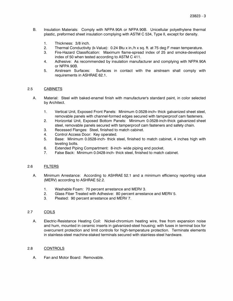
23823 - 3
B. Insulation Materials: Comply with NFPA 90A or NFPA 90B. Unicellular polyethylene thermal
plastic, preformed sheet insulation complying with ASTM C 534, Type II, except for density.
1. Thickness: 3/8 inch.
2. Thermal Conductivity (k-Value): 0.24 Btu x in./h x sq. ft. at 75 deg F mean temperature.
3. Fire-Hazard Classification: Maximum flame-spread index of 25 and smoke-developed index of 50 when tested according to ASTM C 411.
4. Adhesive: As recommended by insulation manufacturer and complying with NFPA 90A
or NFPA 90B.
5. Airstream Surfaces: Surfaces in contact with the airstream shall comply with
requirements in ASHRAE 62.1.
2.5 CABINETS
A. Material: Steel with baked-enamel finish with manufacturer's standard paint, in color selected
by Architect.
1. Vertical Unit, Exposed Front Panels: Minimum 0.0528-inch- thick galvanized sheet steel,
removable panels with channel-formed edges secured with tamperproof cam fasteners. 2. Horizontal Unit, Exposed Bottom Panels: Minimum 0.0528-inch-thick galvanized sheet
steel, removable panels secured with tamperproof cam fasteners and safety chain.
3. Recessed Flanges: Steel, finished to match cabinet.
4. Control Access Door: Key operated.
5. Base: Minimum 0.0528-inch- thick steel, finished to match cabinet, 4 inches high with
leveling bolts.
6. Extended Piping Compartment: 8-inch- wide piping end pocket.
7. False Back: Minimum 0.0428-inch- thick steel, finished to match cabinet.
2.6 FILTERS
A. Minimum Arrestance: According to ASHRAE 52.1 and a minimum efficiency reporting value
(MERV) according to ASHRAE 52.2.
1. Washable Foam: 70 percent arrestance and MERV 3.
2. Glass Fiber Treated with Adhesive: 80 percent arrestance and MERV 5.
3. Pleated: 90 percent arrestance and MERV 7.
2.7 COILS
A. Electric-Resistance Heating Coil: Nickel-chromium heating wire, free from expansion noise
and hum, mounted in ceramic inserts in galvanized-steel housing; with fuses in terminal box for
overcurrent protection and limit controls for high-temperature protection. Terminate elements
in stainless-steel machine-staked terminals secured with stainless-steel hardware.
2.8 CONTROLS
A. Fan and Motor Board: Removable.

23823 - 4
1. Fan: Forward curved, high static, double width, centrifugal, directly connected to motor;
thermoplastic or painted-steel wheels and aluminum, painted-steel, or galvanized-steel
fan scrolls.
2. Motor: Permanently lubricated, multispeed; resiliently mounted on motor board.
Comply with requirements in Section 230513 "Common Motor Requirements for HVAC Equipment."
3. Wiring Terminations: Connect motor to chassis wiring with plug connection.
B. Basic Unit Controls:
1. Control voltage transformer.
2. Unit-mounted thermostat with the following features:
a. Heat-off switch.
b. Fan on-auto switch.
c. Manual fan-speed switch.
d. Adjustable deadband.
e. Concealed set point. f. Concealed indication.
g. Deg F indication.
3. Unit-mounted temperature sensor.
4. Unoccupied period override push button.
5. Data entry and access port.
a. Input data includes room temperature and occupied and unoccupied periods.
b. Output data includes room temperature, supply-air temperature, entering-water
temperature, operating mode, and status.
PART 3 - EXECUTION
3.1 EXAMINATION
A. Examine areas to receive cabinet unit heaters for compliance with requirements for installation
tolerances and other conditions affecting performance of the Work.
B. Examine roughing-in for electrical connections to verify actual locations before unit-heater
installation.
C. Proceed with installation only after unsatisfactory conditions have been corrected.
3.2 INSTALLATION
A. Install wall boxes in finished wall assembly; seal and weatherproof. Joint-sealant materials and
applications are specified in Section 079200 "Joint Sealants."
B. Install cabinet unit heaters to comply with NFPA 90A.
C. Suspend cabinet unit heaters from structure with elastomeric hangers. Vibration isolators are
specified in Section Division 23 "Vibration Controls for HVAC."

23823 - 5
D. Install wall-mounted thermostats and switch controls in electrical outlet boxes at heights to
match lighting controls. Verify location of thermostats and other exposed control sensors with
Drawings and room details before installation.
E. Install new filters in each fan-coil unit within two weeks of Substantial Completion.
3.3 CONNECTIONS
A. Ground equipment according to Division 23 "Grounding and Bonding for Electrical Systems."
B. Connect wiring according to Division 23 "Low-Voltage Electrical Power Conductors and
Cables."
3.4 FIELD QUALITY CONTROL
A. Perform the following tests and inspections with the assistance of a factory-authorized service
representative:
1. Operational Test: After electrical circuitry has been energized, start units to confirm
proper motor rotation and unit operation.
2. Operate electric heating elements through each stage to verify proper operation and
electrical connections. 3. Test and adjust controls and safety devices. Replace damaged and malfunctioning
controls and equipment.
B. Units will be considered defective if they do not pass tests and inspections.
C. Prepare test and inspection reports.
3.5 ADJUSTING
A. Adjust initial temperature set points.
B. Occupancy Adjustments: When requested within 12 months of date of Substantial Completion,
provide on-site assistance in adjusting system to suit actual occupied conditions. Provide up
to two visits to Project during other-than-normal occupancy hours for this purpose.
END OF SECTION 23823
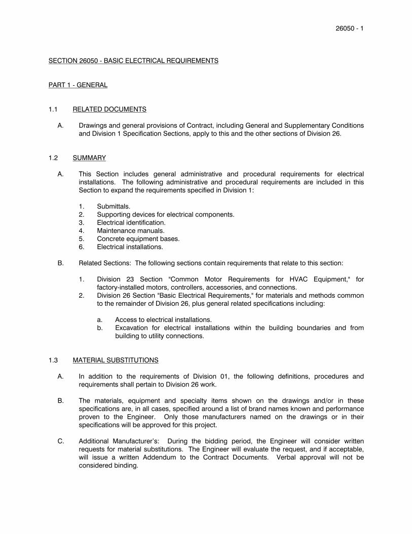
26050 - 1
SECTION 26050 - BASIC ELECTRICAL REQUIREMENTS
PART 1 - GENERAL
1.1 RELATED DOCUMENTS
A. Drawings and general provisions of Contract, including General and Supplementary Conditions
and Division 1 Specification Sections, apply to this and the other sections of Division 26.
1.2 SUMMARY
A. This Section includes general administrative and procedural requirements for electrical
installations. The following administrative and procedural requirements are included in this
Section to expand the requirements specified in Division 1:
1. Submittals.
2. Supporting devices for electrical components.
3. Electrical identification.
4. Maintenance manuals.
5. Concrete equipment bases.
6. Electrical installations.
B. Related Sections: The following sections contain requirements that relate to this section:
1. Division 23 Section "Common Motor Requirements for HVAC Equipment," for
factory-installed motors, controllers, accessories, and connections.
2. Division 26 Section "Basic Electrical Requirements," for materials and methods common
to the remainder of Division 26, plus general related specifications including:
a. Access to electrical installations.
b. Excavation for electrical installations within the building boundaries and from
building to utility connections.
1.3 MATERIAL SUBSTITUTIONS
A. In addition to the requirements of Division 01, the following definitions, procedures and
requirements shall pertain to Division 26 work.
B. The materials, equipment and specialty items shown on the drawings and/or in these
specifications are, in all cases, specified around a list of brand names known and performance
proven to the Engineer. Only those manufacturers named on the drawings or in their
specifications will be approved for this project.
C. Additional Manufacturer’s: During the bidding period, the Engineer will consider written
requests for material substitutions. The Engineer will evaluate the request, and if acceptable,
will issue a written Addendum to the Contract Documents. Verbal approval will not be
considered binding.
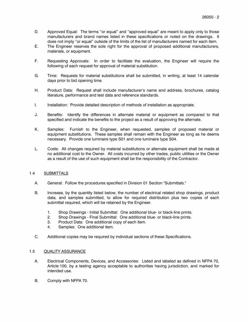
26050 - 2
D. Approved Equal: The terms “or equal” and “approved equal” are meant to apply only to those
manufacturers and brand names listed in these specifications or noted on the drawings. It
does not imply “or equal” outside of the limits of the list of manufacturers named for each item.
E. The Engineer reserves the sole right for the approval of proposed additional manufacturers,
materials, or equipment.
F. Requesting Approvals: In order to facilitate the evaluation, the Engineer will require the
following of each request for approval of material substitution.
G. Time: Requests for material substitutions shall be submitted, in writing, at least 14 calendar
days prior to bid opening time.
H. Product Data: Request shall include manufacturer’s name and address, brochures, catalog
literature, performance and test data and reference standards.
I. Installation: Provide detailed description of methods of installation as appropriate.
J. Benefits: Identify the differences in alternate material or equipment as compared to that
specified and indicate the benefits to the project as a result of approving the alternate.
K. Samples: Furnish to the Engineer, when requested, samples of proposed material or
equipment substitutions. These samples shall remain with the Engineer as long as he deems
necessary. Provide one luminaire type S01 and one luminaire type S04.
L. Costs: All changes required by material substitutions or alternate equipment shall be made at
no additional cost to the Owner. All costs incurred by other trades, public utilities or the Owner
as a result of the use of such equipment shall be the responsibility of the Contractor.
1.4 SUBMITTALS
A. General: Follow the procedures specified in Division 01 Section "Submittals."
B. Increase, by the quantity listed below, the number of electrical related shop drawings, product
data, and samples submitted, to allow for required distribution plus two copies of each
submittal required, which will be retained by the Engineer.
1. Shop Drawings - Initial Submittal: One additional blue- or black-line prints.
2. Shop Drawings - Final Submittal: One additional blue- or black-line prints.
3. Product Data: One additional copy of each item.
4. Samples: One additional item.
C. Additional copies may be required by individual sections of these Specifications.
1.5 QUALITY ASSURANCE
A. Electrical Components, Devices, and Accessories: Listed and labeled as defined in NFPA 70,
Article 100, by a testing agency acceptable to authorities having jurisdiction, and marked for
intended use.
B. Comply with NFPA 70.

26050 - 3 1.6 COORDINATION
A. Coordinate chases, slots, inserts, sleeves, and openings with general construction work and
arrange in building structure during progress of construction to facilitate the electrical
installations that follow.
1. Set inserts and sleeves in poured-in-place concrete, masonry work, and other structural
components as they are constructed.
B. Sequence, coordinate, and integrate installing electrical materials and equipment for efficient
flow of the Work. Coordinate installing large equipment requiring positioning before closing in
the building.
C. Coordinate electrical service connections to components furnished by utility companies.
1. Comply with requirements of authorities having jurisdiction and of utility company
providing electrical power and other services.
D. Coordinate location of access panels and doors for electrical items that are concealed by
finished surfaces. Access doors and panels are specified in Division 8 Section "Access Doors."
E. Where electrical identification devices are applied to field-finished surfaces, coordinate
installation of identification devices with completion of finished surface.
F. Where electrical identification markings and devices will be concealed by acoustical ceilings
and similar finishes, coordinate installation of these items before ceiling installation.
1.7 MAINTENANCE MANUALS
A. Prepare maintenance manuals in accordance with Division 1 Section "Project Closeout." In
addition to the requirements specified in Division 1, include the following information for
equipment items:
1. Description of function, normal operating characteristics and limitations, performance
curves, engineering data and tests, and complete nomenclature and commercial
numbers of replacement parts.
2. Manufacturer's printed operating procedures to include start-up, break-in, and routine
and normal operating instructions; regulation, control, stopping, shutdown, and
emergency instructions; and summer and winter operating instructions.
3. Maintenance procedures for routine preventative maintenance and troubleshooting;
disassembly, repair, and reassembly; aligning and adjusting instructions.
4. Servicing instructions and lubrication charts and schedules.
1.8 DELIVERY, STORAGE, AND HANDLING
A. Deliver products to the project properly identified with names, model numbers, types, grades,
compliance labels, and other information needed for identification.
PART 2 - PRODUCTS
2.1 SUPPORTING DEVICES
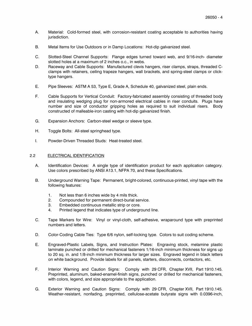
26050 - 4
A. Material: Cold-formed steel, with corrosion-resistant coating acceptable to authorities having
jurisdiction.
B. Metal Items for Use Outdoors or in Damp Locations: Hot-dip galvanized steel.
C. Slotted-Steel Channel Supports: Flange edges turned toward web, and 9/16-inch- diameter
slotted holes at a maximum of 2 inches o.c., in webs.
D. Raceway and Cable Supports: Manufactured clevis hangers, riser clamps, straps, threaded C-
clamps with retainers, ceiling trapeze hangers, wall brackets, and spring-steel clamps or click-
type hangers.
E. Pipe Sleeves: ASTM A 53, Type E, Grade A, Schedule 40, galvanized steel, plain ends.
F. Cable Supports for Vertical Conduit: Factory-fabricated assembly consisting of threaded body
and insulating wedging plug for non-armored electrical cables in riser conduits. Plugs have
number and size of conductor gripping holes as required to suit individual risers. Body
constructed of malleable-iron casting with hot-dip galvanized finish.
G. Expansion Anchors: Carbon-steel wedge or sleeve type.
H. Toggle Bolts: All-steel springhead type.
I. Powder-Driven Threaded Studs: Heat-treated steel.
2.2 ELECTRICAL IDENTIFICATION
A. Identification Devices: A single type of identification product for each application category.
Use colors prescribed by ANSI A13.1, NFPA 70, and these Specifications.
B. Underground Warning Tape: Permanent, bright-colored, continuous-printed, vinyl tape with the
following features:
1. Not less than 6 inches wide by 4 mils thick.
2. Compounded for permanent direct-burial service.
3. Embedded continuous metallic strip or core.
4. Printed legend that indicates type of underground line.
C. Tape Markers for Wire: Vinyl or vinyl-cloth, self-adhesive, wraparound type with preprinted
numbers and letters.
D. Color-Coding Cable Ties: Type 6/6 nylon, self-locking type. Colors to suit coding scheme.
E. Engraved-Plastic Labels, Signs, and Instruction Plates: Engraving stock, melamine plastic
laminate punched or drilled for mechanical fasteners 1/16-inch minimum thickness for signs up
to 20 sq. in. and 1/8-inch minimum thickness for larger sizes. Engraved legend in black letters
on white background. Provide labels for all panels, starters, disconnects, contactors, etc.
F. Interior Warning and Caution Signs: Comply with 29 CFR, Chapter XVII, Part 1910.145.
Preprinted, aluminum, baked-enamel-finish signs, punched or drilled for mechanical fasteners,
with colors, legend, and size appropriate to the application.
G. Exterior Warning and Caution Signs: Comply with 29 CFR, Chapter XVII, Part 1910.145.
Weather-resistant, nonfading, preprinted, cellulose-acetate butyrate signs with 0.0396-inch,
26050 - 5
galvanized-steel backing, with colors, legend, and size appropriate to the application. 1/4-inch
grommets in corners for mounting.
H. Fasteners for Nameplates and Signs: Self-tapping, stainless-steel screws or No. 10/32
stainless-steel machine screws with nuts and flat and lock washers.
2.3 EQUIPMENT FOR UTILITY COMPANY'S ELECTRICITY METERING
A. Meter Sockets: Comply with requirements of electrical power utility company.
2.4 CONCRETE BASES
A. Concrete Forms and Reinforcement Materials: As specified in Division 03 Section "Cast-in-
Place Concrete."
B. Concrete: 3000-psi, 28-day compressive strength as specified in Division 03 Section "Cast-in-
Place Concrete."
2.5 TOUCHUP PAINT
A. For Equipment: Equipment manufacturer's paint selected to match installed equipment finish.
B. Galvanized Surfaces: Zinc-rich paint recommended by item manufacturer.
PART 3 - EXECUTION
3.1 ELECTRICAL EQUIPMENT INSTALLATION
A. Headroom Maintenance: If mounting heights or other location criteria are not indicated,
arrange and install components and equipment to provide the maximum possible headroom.
B. Materials and Components: Install level, plumb, and parallel and perpendicular to other
building systems and components, unless otherwise indicated.
C. Equipment: Install to facilitate service, maintenance, and repair or replacement of components.
Connect for ease of disconnecting, with minimum interference with other installations.
D. Right of Way: Give to raceways and piping systems installed at a required slope.
3.2 ELECTRICAL INSTALLATIONS
A. General: Sequence, coordinate, and integrate the various elements of electrical systems,
materials, and equipment. Comply with the following requirements:
1. Coordinate electrical systems, equipment, and materials installation with other building
components.
2. Verify all dimensions by field measurements.
26050 - 6
3. Arrange for chases, slots, and openings in other building components during progress of
construction, to allow for electrical installations.
4. Coordinate the installation of required supporting devices and sleeves to be set in
poured-in-place concrete and other structural components, as they are constructed.
5. Sequence, coordinate, and integrate installations of electrical materials and equipment
for efficient flow of the Work. Give particular attention to large equipment requiring
positioning prior to closing in the building.
6. Where mounting heights are not detailed or dimensioned, install systems, materials, and
equipment to provide the maximum headroom possible.
7. Coordinate connection of electrical systems with exterior underground and overhead
utilities and services. Comply with requirements of governing regulations, franchised
service companies, and controlling agencies. Provide required connection for each
service.
8. Install systems, materials, and equipment to conform with approved submittal data,
including coordination drawings, to greatest extent possible. Conform to arrangements
indicated by the Contract Documents, recognizing that portions of the Work are shown
only in diagrammatic form. Where coordination requirements conflict with individual
system requirements, refer conflict to the Architect.
9. Install systems, materials, and equipment level and plumb, parallel and perpendicular to
other building systems and components, where installed exposed in finished spaces.
10. Install electrical equipment to facilitate servicing, maintenance, and repair or replacement
of equipment components. As much as practical, connect equipment for ease of
disconnecting, with minimum of interference with other installations.
11. Install access panel or doors where units are concealed behind finished surfaces.
Access panels and doors are specified in Division 08 Section "Access Doors" and
Division 26 Section "Basic Electrical Requirements."
12. Install systems, materials, and equipment giving right-of-way priority to systems required
to be installed at a specified slope.
3.3 ELECTRICAL SUPPORTING METHODS
A. Damp Locations and Outdoors: Hot-dip galvanized materials or nonmetallic, U-channel system
components.
B. Dry Locations: Steel materials.
C. Support Clamps for PVC Raceways: Click-type clamp system.
D. Conform to manufacturer's recommendations for selecting supports.
E. Strength of Supports: Adequate to carry all present and future loads, times a safety factor of at
least 4; 200-lb- minimum design load.
F. Mounting Heights:
1. Mounting heights to bottom of box and above finished floor for the below named items
shall be as follows, unless otherwise shown. All other devices’ mounting heights shall be
as shown on drawings.
a. Flush tumbler switch - 48”.
b. Switches in concrete block - 48”.
c. Switches over wainscot - 6” above 48’ wainscot.

26050 - 7
d. Convenience outlets - 16” mounted vertically with ground prong slot at bottom -
Coordinate height where Fin-Tube Heating Elements are used.
e. Safety switches - 54”.
f. Motor controllers - 54”.
g. Panelboards to top - 72”.
h. Telephone outlets - 16” except Fin-Tube Heating Element locations.
i. Telephone outlets (pay and wall type ) - 52”.
j. Convenience outlets in mechanical, electrical janitor and elevator machine rooms -
+48.
k. Telephone panels - 72” to top.
l. Exterior W.P. convenience - 24” above grade mounted horizontally.
m. Capacitors furnished by Mech. - 36” minimum.
n. Lock-out push button - 36” minimum.
o. Fire alarm pull station - 48”.
p. Fire alarm horn, bell, chime or light - 80”.
2. Contractor shall check all equipment layouts and verify exact mounting heights before
rough-in.
3.4 SUPPORT INSTALLATION
A. Install support devices to securely and permanently fasten and support electrical components.
B. Install individual and multiple raceway hangers and riser clamps to support raceways. Provide
U-bolts, clamps, attachments, and other hardware necessary for hanger assemblies and for
securing hanger rods and conduits.
C. Support parallel runs of horizontal raceways together on trapeze- or bracket-type hangers.
D. Size supports for multiple raceway installations so capacity can be increased by a 25 percent
minimum in the future.
E. Support individual horizontal raceways with separate, malleable-iron pipe hangers or clamps.
F. Install 1/4-inch- diameter or larger threaded steel hanger rods, unless otherwise indicated.
G. Spring-steel fasteners specifically designed for supporting single conduits or tubing may be
used instead of malleable-iron hangers for 1-1/2-inch and smaller raceways serving lighting
and receptacle branch circuits above suspended ceilings and for fastening raceways to slotted
channel and angle supports.
H. Arrange supports in vertical runs so the weight of raceways and enclosed conductors is carried
entirely by raceway supports, with no weight load on raceway terminals.
I. Simultaneously install vertical conductor supports with conductors.
J. Separately support cast boxes that are threaded to raceways and used for fixture support.
Support sheet-metal boxes directly from the building structure or by bar hangers. If bar
hangers are used, attach bar to raceways on opposite sides of the box and support the
raceway with an approved fastener not more than 24 inches from the box.
K. Install metal channel racks for mounting cabinets, panelboards, disconnect switches, control
enclosures, pull and junction boxes, transformers, and other devices unless components are
mounted directly to structural elements of adequate strength.

26050 - 8
L. Install sleeves for cable and raceway penetrations of concrete slabs and walls unless core-
drilled holes are used. Install sleeves for cable and raceway penetrations of masonry and fire-
rated gypsum walls and of all other fire-rated floor and wall assemblies. Install sleeves during
erection of concrete and masonry walls.
M. Securely fasten electrical items and their supports to the building structure, unless otherwise
indicated. Perform fastening according to the following unless other fastening methods are
indicated:
1. Wood: Fasten with wood screws or screw-type nails.
2. Masonry: Toggle bolts on hollow masonry units and expansion bolts on solid masonry
units.
3. New Concrete: Concrete inserts with machine screws and bolts.
4. Existing Concrete: Expansion bolts.
5. Instead of expansion bolts, threaded studs driven by a powder charge and provided with
lock washers may be used in existing concrete.
6. Steel: Welded threaded studs or spring-tension clamps on steel.
a. Field Welding: Comply with AWS D1.1.
7. Welding to steel structure may be used only for threaded studs, not for conduits, pipe
straps, or other items.
8. Light Steel: Sheet-metal screws.
9. Fasteners: Select so the load applied to each fastener does not exceed 25 percent of its
proof-test load.
3.5 IDENTIFICATION MATERIALS AND DEVICES
A. Install at locations for most convenient viewing without interference with operation and
maintenance of equipment.
B. Coordinate names, abbreviations, colors, and other designations used for electrical
identification with corresponding designations indicated in the Contract Documents or required
by codes and standards. Use consistent designations throughout Project.
C. Self-Adhesive Identification Products: Clean surfaces before applying.
D. Tag and label circuits designated to be extended in the future. Identify source and circuit
numbers in each cabinet, pull and junction box, and outlet box. Color-coding may be used for
voltage and phase identification.
E. Install continuous underground plastic markers during trench backfilling, for exterior
underground power, control, signal, and communication lines located directly above power
and communication lines. Locate 6 to 8 inches below finished grade. If width of multiple lines
installed in a common trench or concrete envelope does not exceed 16 inches, overall, use a
single line marker.
F. Color-code 208/120-V system secondary service, feeder, and branch-circuit conductors
throughout the secondary electrical system as follows:
1. Phase A: Black.
2. Phase B: Red.
3. Phase C: Blue.
26050 - 9
4. Neutral: White.
5. Ground: Green.
G. Color-code 480/277-V system secondary service, feeder, and branch-circuit conductors
throughout the secondary electrical system as follows:
1. Phase A: Yellow.
2. Phase B: Brown.
3. Phase C: Orange.
4. Neutral: White with a colored stripe or gray.
5. Ground: Green.
H. Install warning, caution, and instruction signs where required to comply with 29 CFR,
Chapter XVII, Part 1910.145, and where needed to ensure safe operation and maintenance of
electrical systems and of items to which they connect. Install engraved plastic-laminated
instruction signs with approved legend where instructions are needed for system or equipment
operation. Install metal-backed butyrate signs for outdoor items.
I. Install engraved-laminated emergency-operating signs with white letters on red background
with minimum 3/8-inch- high lettering for emergency instructions on power transfer, load
shedding, and other emergency operations.
3.6 UTILITY COMPANY ELECTRICITY-METERING EQUIPMENT
A. Install equipment according to utility company's written requirements. Provide grounding and
empty conduits as required by utility company.
3.7 FIRESTOPPING
A. Apply firestopping to cable and raceway penetrations of fire-rated floor and wall assemblies to
achieve fire-resistance rating of the assembly. Firestopping materials and installation
requirements are specified in Division 7 Section "Firestopping."
3.8 CONCRETE BASES
A. Construct concrete bases of dimensions indicated, but not less than 4 inches larger, in both
directions, than supported unit. Follow supported equipment manufacturer's anchorage
recommendations and setting templates for anchor-bolt and tie locations, unless otherwise
indicated. Use 3000-psi, 28-day compressive-strength concrete and reinforcement as specified
in Division 03 Section "Cast-in-Place Concrete."
3.9 FIELD QUALITY CONTROL
A. Inspect installed components for damage and faulty work, including the following:
1. Supporting devices for electrical components.
2. Electrical identification.
3. Electricity-metering components.
4. Concrete bases.
3.10 REFINISHING AND TOUCHUP PAINTING

26050 - 10
A. Refinish and touch up paint. Paint materials and application requirements are specified in
Division 09 Section "Painting."
1. Clean damaged and disturbed areas and apply primer, intermediate, and finish coats to
suit the degree of damage at each location.
2. Follow paint manufacturer's written instructions for surface preparation and for timing and
application of successive coats.
3. Repair damage to galvanized finishes with zinc-rich paint recommended by
manufacturer.
4. Repair damage to PVC or paint finishes with matching touchup coating recommended by
manufacturer.
3.11 CLEANING AND PROTECTION
A. On completion of installation, including outlets, fittings, and devices, inspect exposed finish.
Remove burrs, dirt, paint spots, and construction debris.
B. Protect equipment and installations and maintain conditions to ensure that coatings, finishes,
and cabinets are without damage or deterioration at time of Substantial Completion.
END OF SECTION 26050
26051 - 1
SECTION 26051 - CONDUCTORS AND CABLES
PART 1 - GENERAL
1.1 RELATED DOCUMENTS
A. Drawings and general provisions of the Contract, including General and Supplementary
Conditions and Division 1 Specification Sections, apply to this Section.
1.2 SUMMARY
A. This Section includes building wires and cables and associated connectors, splices, and
terminations for wiring systems rated 600 V and less.
1.3 SUBMITTALS
A. Product Data: For each type of product indicated.
1.4 QUALITY ASSURANCE
A. Electrical Components, Devices, and Accessories: Listed and labeled as defined in NFPA 70,
Article 100, by a testing agency acceptable to authorities having jurisdiction, and marked for
intended use.
B. Comply with NFPA 70.
PART 2 - PRODUCTS
2.1 MANUFACTURERS
A. In other Part 2 articles where subparagraph titles below introduce lists, the following requirements apply for product selection:
1. Manufacturers: Subject to compliance with requirements, provide products by the
manufacturers specified.
2.2 CONDUCTORS AND CABLES
A. Manufacturers:
1. Alcan Aluminum Corporation; Alcan Cable Div.
2. American Insulated Wire Corp.; a Leviton Company.
3. Colonial.
4. General Cable Corporation.
5. Senator Wire & Cable Company.
6. Southwire Company.
B. Refer to Part 3 "Conductor and Insulation Applications" Article for insulation type, cable
construction, and ratings.
C. Conductor Material: Copper, stranded for No. 12 AWG and larger.

26051 - 2
D. Conductor Insulation Types: Type THHN-THWN complying with NEMA WC.
E. Multiconductor Cable: Armored cable, Type AC, Metal-clad cable, Type MC with ground wire.
2.3 CONNECTORS AND SPLICES
A. Manufacturers:
1. 3M.
2. AMP.
3. Burndy.
4. Ideal.
5. Thomas & Betts Corp.
B. Description: Factory-fabricated connectors and splices of size, ampacity rating, material, type,
and class for application and service indicated.
PART 3 - EXECUTION
3.1 CONDUCTOR AND INSULATION APPLICATIONS
A. Service Entrance: Type THHN-THWN, single conductors in raceway XHHW, single conductors
in raceway.
B. Exposed Feeders: Type THHN-THWN, single conductors in raceway.
C. Feeders Concealed in Ceilings, Walls, and Partitions: Type THHN-THWN, single conductors in
raceway.
D. Feeders Concealed in Concrete, below Slabs-on-Grade, and in Crawlspaces: Type THHN-THWN, single conductors in raceway.
E. Exposed Branch Circuits, including in Crawlspaces: Type THHN-THWN, single conductors in
raceway.
F. Branch Circuits Concealed in Ceilings, Walls, and Partitions: Type THHN-THWN, single
conductors in raceway.
G. Branch Circuits Concealed in Concrete and below Slabs-on-Grade: Type THHN-THWN, single conductors in raceway.
H. MC cable is acceptable in horizontal branch circuits only.
I. Cord Drops and Portable Appliance Connections: Type SO, hard service cord.
J. Fire Alarm Circuits: Power-limited, fire-protective, signaling circuit cable, plenum rated cable.
K. Class 1 Control Circuits: Type THHN-THWN, in raceway.
L. Class 2 Control Circuits: Type THHN-THWN, in raceway.
26051 - 3
3.2 INSTALLATION
A. Conceal cables in finished walls, ceilings, and floors, unless otherwise indicated.
B. Use manufacturer-approved pulling compound or lubricant where necessary; compound used
must not deteriorate conductor or insulation. Do not exceed manufacturer's recommended
maximum pulling tensions and sidewall pressure values.
C. Use pulling means, including fish tape, cable, rope, and basket-weave wire/cable grips, that
will not damage cables or raceway.
D. Install exposed cables parallel and perpendicular to surfaces of exposed structural members,
and follow surface contours where possible.
E. Support cables according to Division 26 Section "Basic Electrical Requirements."
F. Seal around cables penetrating fire-rated elements according to Division 07 Section "Through-
Penetration Firestop Systems."
G. Identify and color-code conductors and cables according to Division 26 Section "Basic
Electrical Requirements."
3.3 CONNECTIONS
A. Tighten electrical connectors and terminals according to manufacturer's published torque-
tightening values. If manufacturer's torque values are not indicated, use those specified in
UL 486A and UL 486B.
B. Make splices and taps that are compatible with conductor material and that possess
equivalent or better mechanical strength and insulation ratings than unspliced conductors.
C. Wiring at Outlets: Install conductor at each outlet, with at least 6 inches of slack.
3.4 FIELD QUALITY CONTROL
A. Testing: Perform the following field quality-control testing:
1. After installing conductors and cables and before electrical circuitry has been energized,
test for compliance with requirements.
2. Perform each electrical test and visual and mechanical inspection stated in NETA ATS, Section 7.3.1. Certify compliance with test parameters.
B. Test Reports: Prepare a written report to record the following:
1. Test procedures used.
2. Test results that comply with requirements.
3. Test results that do not comply with requirements and corrective action taken to achieve
compliance with requirements.
END OF SECTION 26051
26053 - 1
SECTION 26053 - RACEWAYS AND BOXES
PART 1 - GENERAL
1.1 RELATED DOCUMENTS
A. Drawings and general provisions of the Contract, including General and Supplementary
Conditions and Division 1 Specification Sections, apply to this Section.
1.2 SUMMARY
A. This Section includes raceways, fittings, boxes, enclosures, and cabinets for electrical wiring.
1. Raceways include the following:
a. RMC.
b. IMC.
c. EMT.
d. FMC.
e. LFMC.
f. RNC.
g. Surface raceways.
2. Boxes, enclosures, and cabinets include the following:
a. Device boxes.
b. Floor boxes.
c. Outlet boxes.
d. Pull and junction boxes.
B. Related Sections include the following:
1. Division 07 Section "Firestopping."
2. Division 26 Section "Basic Electrical Requirements" for raceways and box supports.
3. Division 26 Section "Wiring Devices" for devices installed in boxes and for floor-box
service fittings.
1.3 DEFINITIONS
A. EMT: Electrical metallic tubing.
B. FMC: Flexible metal conduit.
C. IMC: Intermediate metal conduit.
D. LFMC: Liquidtight flexible metal conduit.
E. RMC: Rigid metal conduit.
26053 - 2
F. RNC: Rigid nonmetallic conduit.
1.4 SUBMITTALS
A. Product Data: For surface raceways, wireways and fittings, floor boxes, and cabinets.
1.5 QUALITY ASSURANCE
A. Listing and Labeling: Provide raceways and boxes specified in this Section that are listed and
labeled.
1. The Terms "Listed" and "Labeled": As defined in NFPA 70, Article 100.
B. Comply with NECA's "Standard of Installation."
C. Comply with NFPA 70.
1.6 COORDINATION
A. Coordinate layout and installation of raceways and boxes with other construction elements to
ensure adequate headroom, working clearance, and access.
PART 2 - PRODUCTS
2.1 MANUFACTURERS
A. Manufacturers: Subject to compliance with requirements, provide products by one of the
following:
1. Metal Conduit and Tubing:
a. Alflex Corp.
b. Anamet, Inc.; Anaconda Metal Hose.
c. Anixter Brothers, Inc.
d. Carol Cable Co., Inc.
e. Cole-Flex Corp.
f. Electri-Flex Co.
g. Flexcon, Inc.; Coleman Cable Systems, Inc.
h. Grinnell Co.; Allied Tube and Conduit Div.
i. Monogram Co.; AFC.
j. Spiraduct, Inc.
k. Triangle PWC, Inc.
l. Wheatland Tube Co.
2. Nonmetallic Conduit:
a. Anamet, Inc.; Anaconda Metal Hose.
b. Arnco Corp.
c. Breeze-Illinois, Inc.
26053 - 3
d. Cantex Industries; Harsco Corp.
e. Certainteed Corp.; Pipe & Plastics Group.
f. Cole-Flex Corp.
g. Condux International; Electrical Products.
h. Electri-Flex Co.
i. George-Ingraham Corp.
j. Hubbell, Inc.; Raco, Inc.
k. Lamson & Sessions; Carlon Electrical Products.
l. R&G Sloan Manufacturing Co., Inc.
m. Spiraduct, Inc.
n. Thomas & Betts Corp.
3. Conduit Bodies and Fittings:
a. American Electric; Construction Materials Group.
b. Crouse-Hinds; Div. of Cooper Industries.
c. Emerson Electric Co.; Appleton Electric Co.
d. Hubbell, Inc.; Killark Electric Manufacturing Co.
e. Lamson & Sessions; Carlon Electrical Products.
f. O-Z/Gedney; Unit of General Signal.
g. Scott Fetzer Co.; Adalet-PLM.
h. Spring City Electrical Manufacturing Co.
4. Surface Metal Raceways:
a. Airey-Thompson Co., Inc.; A-T Power Systems.
b. American Electric; Construction Materials Group.
c. Butler Manufacturing Co.; Walker Division.
d. Wiremold Co. (The); Electrical Sales Division.
5. Boxes and Enclosures:
a. American Electric; FL Industries.
b. Butler Manufacturing Co.; Walker Division.
c. Crouse-Hinds; Div. of Cooper Industries.
d. Electric Panelboard Co., Inc.
e. Erickson Electrical Equipment Co.
f. Hoffman Engineering Co.; Federal-Hoffman, Inc.
g. Hubbell Inc.; Killark Electric Manufacturing Co.
h. Hubbell Inc.; Raco, Inc.
i. Lamson & Sessions; Carlon Electrical Products.
j. O-Z/Gedney; Unit of General Signal.
k. Parker Electrical Manufacturing Co.
l. Robroy Industries, Inc.; Electrical Division.
m. Scott Fetzer Co.; Adalet-PLM.
n. Spring City Electrical Manufacturing Co.
o. Thomas & Betts Corp.
p. Woodhead Industries, Inc.; Daniel Woodhead Co.
2.2 METAL CONDUIT AND TUBING
A. Rigid Steel Conduit: ANSI C80.1.
26053 - 4
B. IMC: ANSI C80.6.
C. EMT and Fittings: ANSI C80.3.
1. Fittings: Set-screw type. Steel. Die-cast is unacceptable.
2. Connectors shall be equipped with insulated throat.
D. FMC: Zinc-coated steel.
E. LFMC: Flexible steel conduit with PVC jacket.
F. Fittings: NEMA FB 1; compatible with conduit/tubing materials.
2.3 NONMETALLIC CONDUIT
A. ENT: Not an approved wiring method.
B. RNC: NEMA TC 2, Schedule 40 or 80 PVC.
C. RNC Fittings: NEMA TC 3; match to conduit or conduit type and material.
2.4 SURFACE RACEWAYS
A. Surface Metal Raceways: Galvanized steel with snap-on covers. Finish with manufacturer's
standard prime coating.
2.5 OUTLET AND DEVICE BOXES
A. Sheet Metal Boxes: NEMA OS 1.
2.6 FLOOR BOXES
A. Floor Boxes: Cast metal, fully adjustable, rectangular.
2.7 PULL AND JUNCTION BOXES
A. Small Sheet Metal Boxes: NEMA OS 1.
PART 3 - EXECUTION
3.1 EXAMINATION
A. Examine surfaces to receive raceways, boxes, enclosures, and cabinets for compliance with
installation tolerances and other conditions affecting performance of raceway installation. Do
not proceed with installation until unsatisfactory conditions have been corrected.
3.2 WIRING METHODS
26053 - 5
A. Outdoors: Use the following wiring methods:
1. Exposed: Rigid steel or IMC.
2. Concealed: Rigid steel or IMC.
3. Underground, Single Run: RNC.
4. Underground, Grouped: RNC.
5. Underground: Conduit underground and located under driveways and paved areas shall
be Schedule 40 PVC encased in concrete to form a 3” wall around conduit or group of
conduits or rigid galvanized steel painted with a heavy continuous coat of asphalt
varnish. Conduit located outside the building area and under grassy areas or sidewalks
shall be Schedule 40 PVC direct buried or rigid galvanized steel painted with a heavy
continuous coat of asphalt varnish. All PVC conduit shall have rigid galvanized steel
elbows. Minimum depth shall be 36”.
6. Connection to Vibrating Equipment (Including Transformers and Hydraulic, Pneumatic,
Electric Solenoid, or Motor-Driven Equipment): LFMC.
7. Boxes and Enclosures: NEMA 250, Type 3R or Type 4.
B. Indoors: Use the following wiring methods:
1. Exposed: EMT.
2. Concealed: EMT.
3. Connection to Vibrating Equipment (Including Transformers and Hydraulic, Pneumatic,
Electric Solenoid, or Motor-Driven Equipment): FMC; except in wet or damp locations,
use LFMC.
4. Damp or Wet Locations: Rigid steel conduit.
5. Boxes and Enclosures: NEMA 250, Type 1, except as follows:
a. Damp or Wet Locations: NEMA 250, Type 4, stainless steel.
b. Damp or Wet Locations: NEMA 250, Type 4, nonmetallic.
3.3 INSTALLATION
A. Install raceways, boxes, enclosures, and cabinets as indicated, according to manufacturer's
written instructions.
B. Minimum Raceway Size: 3/4-inch trade size.
C. Conceal conduit and EMT, unless otherwise indicated, within finished walls, ceilings, and
floors.
D. Keep raceways at least 6 inches away from parallel runs of flues and steam or hot-water pipes.
Install horizontal raceway runs above water and steam piping.
E. Install raceways level and square and at proper elevations. Provide adequate headroom.
F. Complete raceway installation before starting conductor installation.
G. Support raceways as specified in Division 26 Section "Basic Electrical Materials and Methods."
H. Use temporary closures to prevent foreign matter from entering raceways.
26053 - 6
I. Protect stub-ups from damage where conduits rise through floor slabs. Arrange so curved
portion of bends is not visible above the finished slab.
J. Make bends and offsets so ID is not reduced. Keep legs of bends in the same plane and
straight legs of offsets parallel, unless otherwise indicated.
K. Use raceway fittings compatible with raceways and suitable for use and location. For
intermediate steel conduit, use threaded rigid steel conduit fittings, unless otherwise indicated.
L. Run concealed raceways, with a minimum of bends, in the shortest practical distance
considering the type of building construction and obstructions, unless otherwise indicated.
M. Raceways Beneath Slabs: Install beneath or below of slab.
1. Transition from nonmetallic tubing to rigid steel conduit, or IMC before rising above floor.
N. Install exposed raceways parallel to or at right angles to nearby surfaces or structural
members, and follow the surface contours as much as practical.
1. Run parallel or banked raceways together, on common supports where practical.
2. Make bends in parallel or banked runs from same centerline to make bends parallel.
Use factory elbows only where elbows can be installed parallel; otherwise, provide field
bends for parallel raceways.
O. Join raceways with fittings designed and approved for the purpose and make joints tight.
1. Make raceway terminations tight. Use bonding bushings or wedges at connections
subject to vibration. Use bonding jumpers where joints cannot be made tight.
2. Use insulating bushings to protect conductors.
P. Tighten set screws of threadless fittings with suitable tools.
Q. Terminations: Where raceways are terminated with locknuts and bushings, align raceways to
enter squarely and install locknuts with dished part against the box. Where terminations are
not secure with 1 locknut, use 2 locknuts: 1 inside and 1 outside the box.
R. Where raceways are terminated with threaded hubs, screw raceways or fittings tightly into the
hub so the end bears against the wire protection shoulder. Where chase nipples are used,
align raceways so the coupling is square to the box and tighten the chase nipple so no threads
are exposed.
S. Install pull wires in empty raceways. Use No. 14 AWG zinc-coated steel or monofilament
plastic line with not less than 200-lb tensile strength. Leave at least 12 inches of slack at each
end of the pull wire.
T. Stub-up Connections: Extend conduits through concrete floor for connection to freestanding
equipment. Install with an adjustable top or coupling threaded inside for plugs set flush with
the finished floor. Extend conductors to equipment with rigid steel conduit; FMC may be used
6 inches above the floor. Install screwdriver-operated, threaded flush plugs flush with floor for
future equipment connections.
U. Flexible Connections: Use maximum of 6 feet of flexible conduit for recessed and
semirecessed lighting fixtures; for equipment subject to vibration, noise transmission, or
movement; and for all motors. Use liquidtight flexible conduit in wet or damp locations. Install
separate ground conductor across flexible connections.
26053 - 7
V. Surface Raceways: Install a separate, green, ground conductor in raceways from junction box
supplying the raceways to receptacle or fixture ground terminals.
1. Select each surface raceway outlet box, to which a lighting fixture is attached, of
sufficient diameter to provide a seat for the fixture canopy.
2. Where a surface raceway is used to supply a fluorescent lighting fixture having central-
stem suspension with a backplate and a canopy (with or without extension ring), no
separate outlet box is required.
3. Provide surface metal raceway outlet box, and the backplate and canopy, at the feed-in
location of each fluorescent lighting fixture having end-stem suspension.
4. Where a surface metal raceway extension is made from an existing outlet box on which a
lighting fixture is installed, no additional surface-mounted outlet box is required. Provide
a backplate slightly smaller than the fixture canopy.
W. Set floor boxes level and adjust to finished floor surface.
3.4 PROTECTION
A. Provide final protection and maintain conditions, in a manner acceptable to manufacturer and
Installer, that ensure coatings, finishes, and cabinets are without damage or deterioration at the
time of Substantial Completion.
1. Repair damage to galvanized finishes with zinc-rich paint recommended by
manufacturer.
2. Repair damage to PVC or paint finishes with matching touchup coating recommended by
manufacturer.
3.5 CLEANING
A. On completion of installation, including outlet fittings and devices, inspect exposed finish.
Remove burrs, dirt, and construction debris and repair damaged finish, including chips,
scratches, and abrasions.
END OF SECTION 26053
26056 - 1
SECTION 26056 - GROUNDING AND BONDING
PART 1 - GENERAL
1.1 RELATED DOCUMENTS
A. Drawings and general provisions of the Contract, including General and Supplementary
Conditions and Division 01 Specification Sections, apply to this Section.
1.2 SUMMARY
A. This Section includes grounding of electrical systems and equipment. Grounding requirements specified in this Section may be supplemented by special requirements of
systems described in other Sections.
1.3 SUBMITTALS
A. Product Data: For each type of product indicated.
B. Product Data: For the following:
1. Ground rods.
C. Qualification Data: For firms and persons specified in "Quality Assurance" Article.
D. Field Test Reports: Submit written test reports to include the following:
1. Test procedures used.
2. Test results that comply with requirements.
3. Results of failed tests and corrective action taken to achieve test results that comply with requirements.
1.4 QUALITY ASSURANCE
A. Electrical Components, Devices, and Accessories: Listed and labeled as defined in NFPA 70,
Article 100, by a testing agency acceptable to authorities having jurisdiction, and marked for
intended use.
1. Comply with UL 467.
B. Comply with NFPA 70; for overhead-line construction and medium-voltage underground
construction, comply with IEEE C2.
PART 2 - PRODUCTS
2.1 MANUFACTURERS
26056 - 2
A. Manufacturers: Subject to compliance with requirements, provide products by one of the
following:
1. Grounding Conductors, Cables, Connectors, and Rods:
a. Framatome Connectors/Burndy Electrical.
b. Ideal Industries, Inc.
c. Kearney/Cooper Power Systems.
d. O-Z/Gedney Co.; a business of the EGS Electrical Group.
e. Raco, Inc.; Division of Hubbell.
f. Thomas & Betts, Electrical.
2.2 GROUNDING CONDUCTORS A. For insulated conductors, comply with Division 26 Section "Conductors and Cables."
B. Material: Copper.
C. Equipment Grounding Conductors: Insulated with green-colored insulation.
D. Isolated Ground Conductors: Insulated with green-colored insulation with yellow stripe. On
feeders with isolated ground, use colored tape, alternating bands of green and yellow tape to
provide a minimum of three bands of green and two bands of yellow.
E. Grounding Electrode Conductors: Stranded cable.
F. Underground Conductors: Bare, tinned, stranded, unless otherwise indicated.
G. Bare Copper Conductors: Comply with the following:
1. Solid Conductors: ASTM B 3.
2. Assembly of Stranded Conductors: ASTM B 8.
3. Tinned Conductors: ASTM B 33.
H. Copper Bonding Conductors: As follows:
1. Bonding Cable: 28 kcmil, 14 strands of No. 17 AWG copper conductor, 1/4 inch in
diameter.
2. Bonding Conductor: No. 4, stranded copper conductor.
3. Bonding Jumper: Bare copper tape, braided bare copper conductors, terminated with
copper ferrules; 1-5/8 inches wide and 1/16 inch thick.
4. Tinned Bonding Jumper: Tinned-copper tape, braided copper conductors, terminated with copper ferrules; 1-5/8 inches wide and 1/16 inch thick.
2.3 CONNECTOR PRODUCTS
A. Comply with IEEE 837 and UL 467; listed for use for specific types, sizes, and combinations of
conductors and connected items.
B. Bolted Connectors: Bolted-pressure-type connectors, or compression type.
26056 - 3
C. Welded Connectors: Exothermic-welded type, in kit form, and selected per manufacturer's
written instructions.
2.4 GROUNDING ELECTRODES
A. Ground Rods: Copper-clad steel.
1. Size: 3/4 by 120 inches in diameter.
PART 3 - EXECUTION
3.1 APPLICATION
A. Use only copper conductors for both insulated and bare grounding conductors in direct
contact with earth, concrete, masonry, crushed stone, and similar materials.
B. In raceways, use insulated equipment grounding conductors.
C. Exothermic-Welded Connections: Use for connections to structural steel and for underground
connections, except those at test wells.
D. Equipment Grounding Conductor Terminations: Use bolted pressure clamps.
E. Grounding Bus: Install in electrical and telephone equipment rooms, in rooms housing service
equipment, and elsewhere as indicated.
1. Use insulated spacer; space 1 inch from wall and support from wall 6 inches above
finished floor, unless otherwise indicated.
2. At doors, route the bus up to the top of the door frame, across the top of the doorway,
and down to the specified height above the floor.
3.2 EQUIPMENT GROUNDING CONDUCTORS
A. Comply with NFPA 70, Article 250, for types, sizes, and quantities of equipment grounding
conductors, unless specific types, larger sizes, or more conductors than required by NFPA 70
are indicated.
B. Install insulated equipment grounding conductor with circuit conductors for the following
items, in addition to those required by NEC:
1. Feeders and branch circuits.
2. Lighting circuits.
3. Receptacle circuits.
4. Single-phase motor and appliance branch circuits.
5. Three-phase motor and appliance branch circuits.
6. Flexible raceway runs.
7. Armored and metal-clad cable runs.
C. Nonmetallic Raceways: Install an equipment grounding conductor in nonmetallic raceways
unless they are designated for telephone or data cables.

26056 - 4
D. Signal and Communication Systems: For telephone, alarm, voice and data, and other
communication systems, provide No. 4 AWG minimum insulated grounding conductor in
raceway from grounding electrode system to each service location, terminal cabinet, wiring
closet, and central equipment location.
1. Service and Central Equipment Locations and Wiring Closets: Terminate grounding
conductor on a 1/4-by-2-by-12-inch grounding bus.
2. Terminal Cabinets: Terminate grounding conductor on cabinet grounding terminal.
E. Metal Poles Supporting Outdoor Lighting Fixtures: Provide a grounding electrode in addition
to installing a separate equipment grounding conductor with supply branch-circuit conductors.
3.3 INSTALLATION
A. Ground Rods: Install at least three rods spaced at least one-rod length from each other and
located at least the same distance from other grounding electrodes.
1. Drive ground rods until tops are 2 inches below finished floor or final grade, unless
otherwise indicated.
2. Interconnect ground rods with grounding electrode conductors. Use exothermic welds,
except at test wells and as otherwise indicated. Make connections without exposing
steel or damaging copper coating.
B. Grounding Conductors: Route along shortest and straightest paths possible, unless otherwise
indicated. Avoid obstructing access or placing conductors where they may be subjected to
strain, impact, or damage.
C. Bonding Straps and Jumpers: Install so vibration by equipment mounted on vibration isolation
hangers and supports is not transmitted to rigidly mounted equipment. Use exothermic-
welded connectors for outdoor locations, unless a disconnect-type connection is required;
then, use a bolted clamp. Bond straps directly to the basic structure taking care not to
penetrate any adjacent parts. Install straps only in locations accessible for maintenance.
D. Metal Water Service Pipe: Provide insulated copper grounding conductors, in conduit, from
building's main service equipment, or grounding bus, to main metal water service entrances to
building. Connect grounding conductors to main metal water service pipes by grounding
clamp connectors. Where a dielectric main water fitting is installed, connect grounding
conductor to street side of fitting. Bond metal grounding conductor conduit or sleeve to
conductor at each end.
E. Water Meter Piping: Use braided-type bonding jumpers to electrically bypass water meters.
Connect to pipe with grounding clamp connectors.
F. Bond interior metal piping systems and metal air ducts to equipment grounding conductors of
associated pumps, fans, blowers, electric heaters, and air cleaners. Use braided-type bonding
straps.
G. Bond each aboveground portion of gas piping system upstream from equipment shutoff valve.
3.4 CONNECTIONS

26056 - 5
A. General: Make connections so galvanic action or electrolysis possibility is minimized. Select
connectors, connection hardware, conductors, and connection methods so metals in direct
contact will be galvanically compatible.
1. Use electroplated or hot-tin-coated materials to ensure high conductivity and to make
contact points closer to order of galvanic series. 2. Make connections with clean, bare metal at points of contact.
3. Make aluminum-to-steel connections with stainless-steel separators and mechanical
clamps.
4. Make aluminum-to-galvanized steel connections with tin-plated copper jumpers and
mechanical clamps.
5. Coat and seal connections having dissimilar metals with inert material to prevent future
penetration of moisture to contact surfaces.
B. Exothermic-Welded Connections: Comply with manufacturer's written instructions. Welds that
are puffed up or that show convex surfaces indicating improper cleaning are not acceptable.
C. Equipment Grounding Conductor Terminations: For No. 8 AWG and larger, use pressure-type
grounding lugs. No. 10 AWG and smaller grounding conductors may be terminated with
winged pressure-type connectors.
D. Noncontact Metal Raceway Terminations: If metallic raceways terminate at metal housings
without mechanical and electrical connection to housing, terminate each conduit with a
grounding bushing. Connect grounding bushings with a bare grounding conductor to
grounding bus or terminal in housing. Bond electrically non-continuous conduits at entrances and exits with grounding bushings and bare grounding conductors, unless otherwise
indicated.
E. Tighten screws and bolts for grounding and bonding connectors and terminals according to
manufacturer's published torque-tightening values. If manufacturer's torque values are not
indicated, use those specified in UL 486A.
F. Compression-Type Connections: Use hydraulic compression tools to provide correct
circumferential pressure for compression connectors. Use tools and dies recommended by
connector manufacturer. Provide embossing die code or other standard method to make a visible indication that a connector has been adequately compressed on grounding conductor.
G. Moisture Protection: If insulated grounding conductors are connected to ground rods or
grounding buses, insulate entire area of connection and seal against moisture penetration of
insulation and cable.
3.5 FIELD QUALITY CONTROL
A. Testing: Perform the following field quality-control testing:
1. After installing grounding system but before permanent electrical circuitry has been
energized, test for compliance with requirements.
2. Test completed grounding system at each location where a maximum ground-resistance
level is specified, at service disconnect enclosure grounding terminal, and at ground test
wells. Measure ground resistance not less than two full days after the last trace of
precipitation, and without the soil being moistened by any means other than natural
drainage or seepage and without chemical treatment or other artificial means of
reducing natural ground resistance. Perform tests, by the fall-of-potential method according to IEEE 81.
26056 - 6
3. Provide drawings locating each ground rod and ground rod assembly and other
grounding electrodes, identify each by letter in alphabetical order, and key to the record
of tests and observations. Include the number of rods driven and their depth at each
location and include observations of weather and other phenomena that may affect test
results. Describe measures taken to improve test results.
a. Equipment Rated 500 kVA and Less: 10 ohms.
b. Equipment Rated 500 to 1000 kVA: 5 ohms.
c. Equipment Rated More Than 1000 kVA: 3 ohms.
4. Excessive Ground Resistance: If resistance to ground exceeds specified values, notify
Architect promptly and include recommendations to reduce ground resistance.
3.6 GRADING AND PLANTING A. Restore surface features, including vegetation, at areas disturbed by Work of this Section.
Reestablish original grades, unless otherwise indicated. If sod has been removed, replace it
as soon as possible after backfilling is completed. Restore areas disturbed by trenching,
storing of dirt, cable laying, and other activities to their original condition. Include application
of topsoil, fertilizer, lime, seed, sod, sprig, and mulch. Maintain restored surfaces. Restore
disturbed paving as indicated.
END OF SECTION 26056

26092 - 1
SECTION 26092 – LIGHTING CONTROL DEVICES
PART 1 - GENERAL
1.1 RELATED DOCUMENTS
A. Drawings and general provisions of the Contract, including General and Supplementary
Conditions and Division 01 Specification Sections, apply to this Section.
1.2 SUMMARY
A. This Section includes the following lighting control devices:
1. Outdoor photoelectric switches.
2. Multi-pole contactors.
3. Indoor occupancy sensors.
B. Related Sections include the following:
1. Division 26 Section "Wiring Devices" for wall-box dimmers and manual light switches.
1.3 SUBMITTALS
A. Product Data: For each type of product indicated.
B. Field quality-control test reports.
C. Operation and Maintenance Data: For each type of product to include in emergency,
operation, and maintenance manuals.
1.4 QUALITY ASSURANCE
A. Electrical Components, Devices, and Accessories: Listed and labeled as defined in NFPA 70,
Article 100, by a testing agency acceptable to authorities having jurisdiction, and marked for
intended use.
1.5 EXTRA MATERIALS
A. Refer to drawings/schedules for extra materials required.
PART 2 - PRODUCTS
2.1 MANUFACTURERS
26092 - 2
A. In other Part 2 articles where titles below introduce lists, the following requirements apply to
product selection:
1. Manufacturers: Subject to compliance with requirements, provide products by one of
the manufacturers specified.
2.2 GENERAL LIGHTING CONTROL DEVICE REQUIREMENTS
A. Line-Voltage Surge Protection: An integral part of the devices for 120- and 277-V solid-state
equipment. For devices without integral line-voltage surge protection, field-mounting surge
protection shall comply with IEEE C62.41 and with UL 1449.
2.3 OUTDOOR PHOTOELECTRIC SWITCHES
A. Manufacturers:
1. Intermatic, Inc.
2. Paragon Electric Co.
3. Tork.
B. Description: Solid state, with SPST dry contacts rated for 1800-VA tungsten or 1000-VA
inductive, to operate connected relay, contactor coils, microprocessor input, and complying with UL 773A.
1. Light-Level Monitoring Range: 1 to 15 fc, with an adjustment for turn-on and turn-off
levels within that range, and a directional lens in front of photocell to prevent fixed light
sources from causing turn-off.
2. Time Delay: 15-second minimum, to prevent false operation.
2.4 MULTI-POLE CONTACTORS
A. Manufacturers:
1. Square D; a brand of Schneider Electric.
2. General Electric Company; GE Consumer & Industrial – Electrical Distribution.
B. Description: Electrically operated and electrically held, complying with NEMA ICS 2 and
UL 508.
1. Current Rating for Switching: Refer to Drawings.
2. Control-Coil Voltage: Match control power source.
3. Manual Control: Unit mounted HOA for exterior lighting contactors.
2.5 CONDUCTORS AND CABLES
A. Power Wiring to Supply Side of Remote-Control Power Sources: Not smaller than No. 12
AWG, complying with Division 26 Section "Conductors and Cables."
2.6 INDOOR OCCUPANCY SENSORS
26092 - 3
A. Manufacturers:
1. Hubbell Lighting Inc.
2. Novitas, Inc.
3. Watt Stopper (The).
B. General Description: Wall- or ceiling-mounting, solid-state units with a separate relay unit.
1. Operation: Unless otherwise indicated, turn lights on when covered area is occupied
and off when unoccupied; with a time delay for turning lights off, adjustable over a
minimum range of 1 to 15 minutes.
2. Sensor Output: Contacts rated to operate the connected relay, complying with UL 773A.
Sensor shall be powered from the relay unit.
3. Relay Unit: Dry contacts rated for 20-A ballast load at 120- and 277-V ac, for 13-A
tungsten at 120-V ac, and for 1 hp at 120-V ac. Power supply to sensor shall be 24-V dc,
150-mA, Class 2 power source as defined by NFPA 70.
4. Mounting:
a. Sensor: Suitable for mounting in any position on a standard outlet box. b. Relay: Externally mounted though a 1/2-inch knockout in a standard electrical
enclosure.
c. Time-Delay and Sensitivity Adjustments: Recessed and concealed behind hinged
door.
5. Indicator: LED, to show when motion is being detected during testing and normal
operation of the sensor.
6. Bypass Switch: Override the on function in case of sensor failure.
7. Automatic Light-Level Sensor: Adjustable from 2 to 200 fc; keeps lighting off when
selected lighting level is present.
C. PIR Type: Ceiling mounting; detect occupancy by sensing a combination of heat and
movement in area of coverage.
1. Detector Sensitivity: Detect occurrences of 6-inch minimum movement of any portion of
a human body that presents a target of at least 36 sq. in.
2. Detection Coverage (Room): Detect occupancy anywhere in a circular area of 1000 sq.
ft. when mounted on a 96-inch-high ceiling.
3. Detection Coverage (Corridor): Detect occupancy within 90 feet when mounted on a 10-
foot-high ceiling.
D. Ultrasonic Type: Ceiling mounting; detect occupancy by sensing a change in pattern of
reflected ultrasonic energy in area of coverage.
1. Detector Sensitivity: Detect a person of average size and weight moving at least 12
inches in either a horizontal or a vertical manner at an approximate speed of 12 inches/s.
2. Detection Coverage (Small Room): Detect occupancy anywhere within a circular area of
600 sq. ft. when mounted on a 96-inch-high ceiling.
3. Detection Coverage (Standard Room): Detect occupancy anywhere within a circular
area of 1000 sq. ft. when mounted on an 8-foot-high ceiling.
4. Detection Coverage (Large Room): Detect occupancy anywhere within a circular area of
2000 sq. ft. when mounted on a 96-inch-high ceiling.
5. Detection Coverage (Corridor): Detect occupancy anywhere within 90 feet when mounted on a 10-foot-high ceiling in a corridor not wider than 14 feet.
26092 - 4
E. Dual-Technology Type: Ceiling mounting; detect occupancy by using a combination of PIR
and ultrasonic detection methods in area of coverage. Particular technology or combination of
technologies that controls on and off functions shall be selectable in the field by operating
controls on unit.
1. Sensitivity Adjustment: Separate for each sensing technology. 2. Detector Sensitivity: Detect occurrences of 6-inch minimum movement of any portion of
a human body that presents a target of at least 36 sq. in., and detect a person of
average size and weight moving at least 12 inches in either a horizontal or a vertical
manner at an approximate speed of 12 inches/s.
3. Detection Coverage (Standard Room): Detect occupancy anywhere within a circular
area of 1000 sq. ft. when mounted on a 96-inch-high ceiling.
PART 3 - EXECUTION
3.1 SENSOR INSTALLATION
A. Install and aim sensors in locations to achieve at least 90 percent coverage of areas indicated.
Do not exceed coverage limits specified in manufacturer's written instructions.
3.2 WIRING INSTALLATION
A. Wiring Method: Comply with Division 26 Section "Conductors and Cables." Minimum conduit
size shall be 3/4-inch.
B. Wiring within Enclosures: Bundle, lace, and train conductors to terminal points. Separate
power-limited and non-power limited conductors according to conductor manufacturer's
written instructions.
C. Splices, Taps, and Terminations: Make connections only on numbered terminal strips in
junction, pull, and outlet boxes; terminal cabinets; and equipment enclosures.
D. Tighten electrical connectors and terminals according to manufacturer's published torque-tightening values. If manufacturer's torque values are not indicated, use those specified in
UL 486A.
3.3 IDENTIFICATION
A. Identify components and power and control wiring.
B. Label time switches and contactors with a unique designation.
3.4 FIELD QUALITY CONTROL
A. Perform the following field tests and inspections and prepare test reports:
1. After installing time switches and sensors, and after electrical circuitry has been
energized, adjust and test for compliance with requirements.
2. Operational Test: Verify actuation of each sensor and adjust time delays.
26092 - 5
B. Remove and replace lighting control devices where test results indicate that they do not
comply with specified requirements.
C. Additional testing and inspecting, at Contractor's expense, will be performed to determine
compliance of replaced or additional work with specified requirements.
3.5 ADJUSTING
A. Occupancy Adjustments: When requested within 12 months of date of Substantial
Completion, provide on-site assistance in adjusting sensors to suit actual occupied conditions.
Provide up to two visits to site outside normal occupancy hours for this purpose.
END OF SECTION 26092
26246 - 1
SECTION 26246 - PANELBOARDS
PART 1 - GENERAL
1.1 RELATED DOCUMENTS
A. Drawings and general provisions of the Contract, including General and Supplementary
Conditions and Division 1 Specification Sections, apply to this Section.
1.2 SUMMARY
A. This Section includes load centers and panelboards, overcurrent protective devices, and associated auxiliary equipment rated 600 V and less for the following types:
1. Lighting and appliance branch-circuit panelboards.
2. Distribution panelboards.
B. Related Sections include the following:
1. Division 26 Section "Fuses."
1.3 DEFINITIONS
A. EMI: Electromagnetic interference.
B. GFCI: Ground-fault circuit interrupter.
C. RFI: Radio-frequency interference.
D. RMS: Root mean square.
E. SPDT: Single pole, double throw.
1.4 SUBMITTALS
A. Product Data: For each type of panelboard, overcurrent protective device, TVSS device,
accessory, and component indicated. Include dimensions and manufacturers' technical data
on features, performance, electrical characteristics, ratings, and finishes.
B. Shop Drawings: For each panelboard and related equipment.
1. Dimensioned plans, elevations, sections, and details. Show tabulations of installed
devices, equipment features, and ratings. Include the following:
a. Enclosure types and details for types other than NEMA 250, Type 1.
b. Bus configuration, current, and voltage ratings.
c. Short-circuit current rating of panelboards and overcurrent protective devices.
d. UL listing for series rating of installed devices.
26246 - 2
e. Features, characteristics, ratings, and factory settings of individual overcurrent
protective devices and auxiliary components.
2. Wiring Diagrams: Diagram power, signal, and control wiring and differentiate between
manufacturer-installed and field-installed wiring.
C. Field Test Reports: Submit written test reports and include the following:
1. Test procedures used.
2. Test results that comply with requirements.
3. Results of failed tests and corrective action taken to achieve test results that comply with
requirements.
D. Panelboard Schedules: For installation in panelboards. Submit final versions after load
balancing.
E. Maintenance Data: For panelboards and components to include in maintenance manuals
specified in Division 1. In addition to requirements specified in Division 1 Section "Contract
Closeout," include the following:
1. Manufacturer's written instructions for testing and adjusting overcurrent protective
devices.
2. Time-current curves, including selectable ranges for each type of overcurrent protective
device.
1.5 QUALITY ASSURANCE
A. Electrical Components, Devices, and Accessories: Listed and labeled as defined in NFPA 70,
Article 100, by a testing agency acceptable to authorities having jurisdiction, and marked for
intended use.
B. Comply with NEMA PB 1.
C. Comply with NFPA 70.
1.6 COORDINATION
A. Coordinate layout and installation of panelboards and components with other construction that
penetrates walls or is supported by them, including electrical and other types of equipment,
raceways, piping, and encumbrances to workspace clearance requirements.
PART 2 - PRODUCTS
2.1 MANUFACTURERS
A. Manufacturers: Subject to compliance with requirements, provide products by one of the
following:
1. Panelboards, Overcurrent Protective Devices, Controllers, Contactors, and Accessories:
a. Eaton Corp.; Cutler-Hammer Products.

26246 - 3
b. General Electric Co.; Electrical Distribution & Control Div.
c. Square D Co.
2.2 FABRICATION AND FEATURES
A. Enclosures: Flush and surface mounted cabinets. NEMA PB 1, Type 1, to meet environmental
conditions at installed location.
1. Outdoor Locations: NEMA 250, Type 3R.
2. Kitchen Areas: NEMA 250, Type 4X, stainless steel.
3. Other Wet or Damp Indoor Locations: NEMA 250, Type 4.
4. Hazardous Areas Indicated on Drawings: NEMA 250, Type 7C.
B. Hinged Front Cover: Entire front trim hinged to box and with standard door within hinged trim cover.
C. Finish: Manufacturer's standard enamel finish over corrosion-resistant treatment or primer
coat.
D. Directory Card: With transparent protective cover, mounted inside metal frame, inside
panelboard door.
E. Bus: Hard-drawn copper, 98 percent conductivity.
F. Main and Neutral Lugs: Mechanical type suitable for use with conductor material.
G. Equipment Ground Bus: Adequate for feeder and branch-circuit equipment ground
conductors; bonded to box.
H. Service Equipment Label: UL labeled for use as service equipment for panelboards with main
service disconnect switches.
I. Future Devices: Mounting brackets, bus connections, and necessary appurtenances required for future installation of devices.
J. Isolated Equipment Ground Bus: Adequate for branch-circuit equipment ground conductors;
insulated from box.
K. Neutral Bus: Neutral bus rated 100 percent of phase bus and UL listed as suitable for
nonlinear loads.
L. Feed-through Lugs: Mechanical type suitable for use with conductor material. Locate at opposite end of bus from incoming lugs or main device.
2.3 PANELBOARD SHORT-CIRCUIT RATING
A. UL label indicating series-connected rating with integral or remote upstream devices. Include
size and type of upstream device allowable, branch devices allowable, and UL series-
connected short-circuit rating.
2.4 LIGHTING AND APPLIANCE BRANCH-CIRCUIT PANELBOARDS
26246 - 4
A. Branch Overcurrent Protective Devices: Bolt-on circuit breakers, replaceable without
disturbing adjacent units.
B. Doors: Hinged front cover with standard door within hinged cover; secured with flush latch with tumbler lock; keyed alike.
2.5 DISTRIBUTION PANELBOARDS
A. Doors: Hinged front cover with standard door within cover, except omit in fused-switch
panelboards; secured with vault type latch with tumbler lock; keyed alike.
B. Main Overcurrent Protective Devices: Circuit breaker.
C. Branch overcurrent protective devices shall be one of the following:
1. For Circuit-Breaker Frame Sizes 125 A and Smaller: Bolt-on circuit breakers.
2. For Circuit-Breaker Frame Sizes Larger Than 125 A: Bolt-on circuit breakers; plug-in
circuit breakers where individual positive-locking device requires mechanical release for
removal.
3. Fused switches.
2.6 TVSS PANELBOARDS
A. Doors: Hinged front cover with standard door within hinged cover; secured with flush latch
with tumbler lock; keyed alike.
B. Main Overcurrent Devices: Thermal-magnetic circuit breaker.
C. Branch Overcurrent Protective Devices: Bolt-on circuit breakers.
D. Bus: Copper phase and neutral buses; 200 percent capacity neutral bus when called for.
E. TVSS Device: IEEE C62.41, integrally mounted, plug-in-style, solid-state, parallel-connected,
sine-wave tracking suppression and filtering modules.
1. Direct bus termination to panelboard bus by panelboard manufacturer, where tandem
panel tubs are called for, direct bus termination shall be ahead of feed-through lugs.
2. Peak single impulse surge current rating: 100 kA per phase.
a. Line to Neutral: 50 kA.
b. Line to Ground: 50 kA.
c. Neutral to Ground: 50 kA.
3. Protection modes shall be as follows:
a. Line to neutral.
b. Line to ground.
c. Neutral to ground.
4. EMI/RFI Noise Attenuation Using 50-ohm Insertion Loss Test: 55 dB at 100 kHz
complying with UL 1283.
26246 - 5
5. UL 1449 Second Edition clamping levels shall not exceed 400V, line to neutral, line to
ground, and neutral to ground on 120/208V systems and 800V, line to neutral, line to
ground, and neutral to ground on 277/480V systems.
6. Withstand Capabilities: 3000 Category C surges with less than 5 percent change in
clamping voltage. 7. Accessories shall include the following:
a. Form-C contacts, one normally open and one normally closed, for remote
monitoring of system operation. Contacts to reverse position on failure of any
surge diversion module.
b. Audible alarm activated on failure of any surge diversion module with alarm
silence as well as push-to-test switch.
c. Six-digit transient-counter set to total transient surges that deviate from the sine-
wave envelope by more than 125 V.
d. Red and green solid state indicating lights with front cover printed labels to
indicate line status. The absence of green light and presence of a red light shall indicate a reduction in the unit’s surge protection and service is required.
2.7 OVERCURRENT PROTECTIVE DEVICES
A. Molded-Case Circuit Breaker: NEMA AB 1, with interrupting capacity to meet available fault
currents.
1. Thermal-Magnetic Circuit Breakers: Inverse time-current element for low-level overloads, and instantaneous magnetic trip element for short circuits. Adjustable magnetic trip
setting for circuit-breaker frame sizes 250 A and larger.
2. Adjustable Instantaneous-Trip Circuit Breakers: Magnetic trip element with front-
mounted, field-adjustable trip setting.
3. Current-Limiting Circuit Breakers: Frame sizes 400 A and smaller; let-through ratings
less than NEMA FU 1, RK-5.
4. Integrally Fused Circuit Breakers: Thermal-magnetic trip element with integral limiter-
style fuse listed for use with circuit breaker; trip activation on fuse opening or on opening
of fuse compartment door.
5. GFCI Circuit Breakers: Single- and two-pole configurations with 5-mA trip sensitivity.
B. Molded-Case Circuit-Breaker Features and Accessories. Standard frame sizes, trip ratings,
and number of poles.
1. Lugs: Mechanical style, suitable for number, size, trip ratings, and material of
conductors.
2. Application Listing: Appropriate for application; Type SWD for switching fluorescent
lighting loads; Type HACR for heating, air-conditioning, and refrigerating equipment.
3. Ground-Fault Protection: Integrally mounted relay and trip unit with adjustable pickup and time-delay settings, push-to-test feature, and ground-fault indicator.
4. Shunt Trip: 120-V trip coil energized from separate circuit, set to trip at 75 percent of
rated voltage.
5. Key Interlock Kit: Externally mounted to prohibit circuit-breaker operation; key shall be
removable only when circuit breaker is in off position.
2.8 ACCESSORY COMPONENTS AND FEATURES
26246 - 6
A. Accessory Set: Tools and miscellaneous items required for overcurrent protective device test,
inspection, maintenance, and operation.
PART 3 - EXECUTION
3.1 INSTALLATION
A. Install panelboards and accessories according to NEMA PB 1.1.
B. Mounting Heights: Top of trim 74 inches above finished floor, unless otherwise indicated.
C. Mounting: Plumb and rigid without distortion of box. Mount recessed panelboards with fronts
uniformly flush with wall finish.
D. Circuit Directory: Create a directory to indicate installed circuit loads after balancing
panelboard loads. Obtain approval before installing. Use a computer or typewriter to create
directory; handwritten directories are not acceptable.
E. Install filler plates in unused spaces.
F. Provision for Future Circuits at Flush Panelboards: Stub six 1-inch empty conduits from
panelboard into accessible ceiling space or space designated to be ceiling space in the future.
Stub six 1-inch empty conduits into raised floor space or below slab not on grade.
G. Wiring in Panelboard Gutters: Arrange conductors into groups and bundle and wrap with wire
ties after completing load balancing.
3.2 IDENTIFICATION
A. Identify field-installed conductors, interconnecting wiring, and components; provide warning
signs as specified in Division 26 Section "Basic Electrical Materials and Methods.”
B. Panelboard Nameplates: Label each panelboard with engraved laminated-plastic nameplate
mounted with corrosion-resistant screws.
3.3 CONNECTIONS
A. Install equipment grounding connections for panelboards with ground continuity to main
electrical ground bus.
B. Tighten electrical connectors and terminals according to manufacturer's published torque-
tightening values. If manufacturer's torque values are not indicated, use those specified in
UL 486A.
3.4 FIELD QUALITY CONTROL
A. Prepare for acceptance tests as follows:
1. Test insulation resistance for each panelboard bus, component, connecting supply,
feeder, and control circuit.

26246 - 7
2. Test continuity of each circuit.
B. Testing: After installing panelboards and after electrical circuitry has been energized,
demonstrate product capability and compliance with requirements.
1. Procedures: Perform each visual and mechanical inspection and electrical test indicated
in NETA ATS, Section 7.5 for switches and Section 7.6 for molded-case circuit breakers.
Certify compliance with test parameters.
2. Correct malfunctioning units on-site, where possible, and retest to demonstrate
compliance; otherwise, replace with new units and retest.
C. Balancing Loads: After Substantial Completion, but not more than 60 days after Final
Acceptance, measure load balancing and make circuit changes as follows:
1. Measure as directed during period of normal system loading. 2. Perform load-balancing circuit changes outside normal occupancy/working schedule of
the facility and at time directed. Avoid disrupting critical 24-hour services such as fax
machines and on-line data-processing, computing, transmitting, and receiving
equipment.
3. After circuit changes, recheck loads during normal load period. Record all load readings
before and after changes and submit test records.
4. Tolerance: Difference exceeding 20 percent between phase loads, within a panelboard,
is not acceptable. Rebalance and recheck as necessary to meet this minimum
requirement.
3.5 ADJUSTING
A. Set field-adjustable switches and circuit-breaker trip ranges.
3.6 CLEANING
A. On completion of installation, inspect interior and exterior of panelboards. Remove paint splatters and other spots. Vacuum dirt and debris; do not use compressed air to assist in
cleaning. Repair exposed surfaces to match original finish.
END OF SECTION 26246
26276 - 1
SECTION 26276 - WIRING DEVICES
PART 1 - GENERAL
1.1 RELATED DOCUMENTS
A. Drawings and general provisions of the Contract, including General and Supplementary
Conditions and Division 1 Specification Sections, apply to this Section.
1.2 SUMMARY
A. This Section includes receptacles, connectors, switches, and finish plates.
1.3 DEFINITIONS
A. GFCI: Ground-fault circuit interrupter.
1.4 SUBMITTALS
A. Product Data: For each product specified.
B. Shop Drawings: Legends for receptacles and switch plates.
C. Maintenance Data: For materials and products to include in maintenance manuals specified in
Division 01.
1.5 QUALITY ASSURANCE
A. Electrical Components, Devices, and Accessories: Listed and labeled as defined in NFPA 70,
Article 100, by a testing agency acceptable to authorities having jurisdiction.
B. Comply with NEMA WD 1.
C. Comply with NFPA 70.
1.6 COORDINATION
A. Receptacles for Owner-Furnished Equipment: Match plug configurations, coordinate all work
with Owner.
1. Cord and Plug Sets: Match equipment requirements.
PART 2 - PRODUCTS
26276 - 2
2.1 MANUFACTURERS
A. Manufacturers: Subject to compliance with requirements, provide products by one of the
following:
1. Wiring Devices: Color gray.
a. GE Company; #5362 series.
b. Hubbell, Inc.; #5352 series.
c. Leviton Manufacturing Co., Inc., #5362 series.
d. Pass & Seymour, #5362 series, color by Architect.
2. Multioutlet Assemblies:
a. Leviton.
b. Wiremold.
3. Poke-through, Floor Service Outlets and Telephone/Power Poles:
a. Hubbell, Inc.; Wiring Devices Div.
b. Pass & Seymour/Legrand; Wiring Devices Div.
c. Square D Co.
d. Wiremold.
2.2 RECEPTACLES
A. Straight-Blade and Locking Receptacles: Heavy-Duty grade.
B. GFCI Receptacles: Feed-through type, with integral NEMA WD 6, Configuration 5-20R duplex
receptacle arranged to protect connected downstream receptacles on same circuit. Design
units for installation in a 2-3/4-inch-deep outlet box without an adapter.
2.3 PENDANT CORD/CONNECTOR DEVICES
A. Description: Matching, locking type, plug and receptacle body connector, NEMA WD 6,
Configurations L5-20P and L5-20R, Heavy-Duty grade.
1. Body: Nylon with screw-open cable-gripping jaws and provision for attaching external
cable grip.
2. External Cable Grip: Woven wire-mesh type made of high-strength galvanized-steel wire
strand, matched to cable diameter, and with attachment provision designed for
corresponding connector.
2.4 CORD AND PLUG SETS
A. Description: Match voltage and current ratings and number of conductors to requirements of
equipment being connected.
1. Cord: Rubber-insulated, stranded-copper conductors, with type SOW-A jacket. Green-
insulated grounding conductor, and equipment-rating ampacity plus a minimum of 30
percent.
26276 - 3
2. Plug: Nylon body and integral cable-clamping jaws. Match cord and receptacle type for
connection.
2.5 SWITCHES
A. Snap Switches: Heavy-duty, quiet type.
B. Dimmer Switches: Modular, full-wave, solid-state units with integral, quiet on/off switches and
audible and electromagnetic noise filters.
1. Lutron Nova Series.
2. Prescolite Horizon Series.
3. Control: Continuously adjustable slide, toggle, or rotary knob. Single-pole or three-way
switch to suit connections.
4. Incandescent Lamp Dimmers: Modular, 120 V, 60 Hz with continuously adjustable rotary
knob, toggle, or slide; single pole with soft tap or other quiet switch; electromagnetic filter
to eliminate noise, RF, and TV interference; and 5-inch wire connecting leads.
a. Lutron Nova Series.
b. Prescolite Horizon Series.
2.6 WALL PLATES
A. Single and combination types match corresponding wiring devices.
1. Plate-Securing Screws: Metal with head color to match plate finish.
2. Material for Finished Spaces: 0.04-inch-thick, Type 302, satin-finished stainless steel.
2.7 MULTIOUTLET ASSEMBLIES
A. Components of Assemblies: Products from a single manufacturer designed for use as a
complete, matching assembly of raceways and receptacles.
B. Raceway Material: Metal, with manufacturer's standard finish.
C. Wire: No. 12 AWG.
2.8 FINISHES
A. Color: Manufacturers standard, as selected by Architect.
PART 3 - EXECUTION
3.1 INSTALLATION
A. Install devices and assemblies plumb and secure.
B. Install wall plates when painting is complete.

26276 - 4
C. Install wall dimmers to achieve indicated rating after derating for ganging as instructed by
manufacturer.
D. Do not share neutral conductor on load side of dimmers.
E. Arrangement of Devices: Unless otherwise indicated, mount flush, with long dimension
vertical, and grounding terminal of receptacles on top. Group adjacent switches under single,
multigang wall plates.
F. Protect devices and assemblies during painting.
G. Adjust locations at which floor service outlets and telephone/power service poles are installed
to suit arrangement of partitions and furnishings.
3.2 IDENTIFICATION
A. Comply with Division 26 Section "Basic Electrical Requirements."
1. Switches: Where three or more switches are ganged, and elsewhere as indicated,
identify each switch with approved legend engraved on wall plate.
2. Receptacles: Identify panelboard and circuit number from which served. Use machine-
printed, pressure-sensitive, abrasion-resistant label tape on face of plate or indelible ink
on back of face plate or tags within outlet boxes.
3.3 CONNECTIONS
A. Connect wiring device grounding terminal to branch-circuit equipment grounding conductor.
B. Tighten electrical connectors and terminals according to manufacturers published torque-
tightening values. If manufacturers torque values are not indicated, use those specified in UL
486A and UL 486B.
3.4 FIELD QUALITY CONTROL
A. Test wiring devices for proper polarity and ground continuity. Operate each device at least six
times.
B. Test GFCI operation with both local and remote fault simulations according to manufacturer's
written instructions.
C. Replace damaged or defective components.
3.5 CLEANING
A. Internally clean devices, device outlet boxes, and enclosures. Replace stained or improperly
painted wall plates or devices.
END OF SECTION 26276

26283 - 1
SECTION 26283 - FUSES
PART 1 - GENERAL
1.1 RELATED DOCUMENTS
A. Drawings and general provisions of the Contract, including General and Supplementary
Conditions and Division 01 Specification Sections, apply to this Section.
1.2 SUMMARY
A. This Section includes cartridge fuses, rated 600 V and less, for use in switches, panelboards, switchboards, controllers, and motor-control centers; and spare fuse cabinets.
1.3 SUBMITTALS
A. Product Data: Include dimensions and manufacturer's technical data on features,
performance, electrical characteristics, and ratings for each fuse type indicated.
B. Product Data: Include the following for each fuse type indicated:
1. Dimensions and manufacturer's technical data on features, performance, electrical
characteristics, and ratings.
2. Let-through current curves for fuses with current-limiting characteristics.
3. Time-current curves, coordination charts and tables, and related data.
4. Fuse size for elevator feeders and elevator disconnect switches.
C. Ambient Temperature Adjustment Information. If ratings of fuses have been adjusted to
accommodate ambient temperatures, provide list of fuses adjusted.
1. For each adjusted fuse, include location of fuse, original fuse rating, local ambient
temperature, and adjusted fuse rating.
2. Provide manufacturer's technical data on which ambient temperature adjustment
calculations are based.
D. Maintenance Data: For tripping devices to include in maintenance manuals specified in
Division 01.
1.4 QUALITY ASSURANCE
A. Source Limitations: Provide fuses from a single manufacturer.
B. Electrical Components, Devices, and Accessories: Listed and labeled as defined in NFPA 70,
Article 100, by a testing agency acceptable to authorities having jurisdiction, and marked for
intended use.
C. Comply with NEMA FU 1.
26283 - 2
D. Comply with NFPA 70.
1.5 PROJECT CONDITIONS
A. Where ambient temperature to which fuses are directly exposed is less than 40 deg F or more than 100 deg F, apply manufacturer's ambient temperature adjustment factors to fuse ratings.
1.6 COORDINATION
A. Coordinate fuse ratings with HVAC and refrigeration equipment nameplate limitations of
maximum fuse size.
1.7 EXTRA MATERIALS
A. Furnish extra materials described below that match products installed and that are packaged
in original cartons or containers and identified with labels describing contents.
1. Fuses: Quantity equal to 10 percent of each fuse type and size, but not fewer than one
of each type and size.
PART 2 - PRODUCTS
2.1 MANUFACTURERS
A. Manufacturers: Subject to compliance with requirements, provide products by one of the
following:
1. Cooper Industries, Inc.; Bussmann Div.
2. Gould Shawmut.
3. Tracor, Inc.; Littelfuse, Inc. Subsidiary.
2.2 CARTRIDGE FUSES
A. Characteristics: NEMA FU 1, nonrenewable cartridge fuse; class and current rating indicated;
voltage rating consistent with circuit voltage.
2.3 SPARE FUSE CABINET
A. Cabinet: Wall-mounted, 0.05-inch-thick steel unit with full-length, recessed piano-hinged door
and key-coded cam lock and pull.
1. Size: Adequate for storage of spare fuses specified with 15 percent spare capacity
minimum.
2. Finish: Gray, baked enamel.
3. Identification: "SPARE FUSES" in 1-1/2-inch-high letters on exterior of door.
4. Fuse Pullers: For each size fuse.
26283 - 3
PART 3 - EXECUTION
3.1 EXAMINATION
A. Examine utilization equipment nameplates and installation instructions. Install fuses of sizes
and with characteristics appropriate for each piece of equipment.
B. Evaluate ambient temperatures to determine if fuse rating adjustment factors must be applied
to fuse ratings.
C. Proceed with installation only after unsatisfactory conditions have been corrected.
3.2 FUSE APPLICATIONS
A. Main Service: Class L, time delay.
B. Main Feeders: Class L, time delay.
C. Motor Branch Circuits: Class RK5, time delay.
D. Other Branch Circuits: Class RK1, time delay.
3.3 INSTALLATION
A. Install fuses in fusible devices. Arrange fuses so rating information is readable without
removing fuse.
B. Install spare fuse cabinet, located next to MDP.
3.4 IDENTIFICATION
A. Install labels indicating fuse replacement information on inside door of each fused switch.
END OF SECTION 26283
26286 - 1
SECTION 26286 - ENCLOSED SWITCHES AND CIRCUIT BREAKERS
PART 1 - GENERAL
1.1 RELATED DOCUMENTS
A. Drawings and general provisions of the Contract, including General and Supplementary
Conditions and other Division 01 Specification Sections, apply to this Section.
1.2 SUMMARY
A. Section Includes:
1. Fusible switches.
2. Nonfusible switches.
3. Molded-case circuit breakers (MCCBs).
4. Molded-case switches.
5. Enclosures.
1.3 DEFINITIONS
A. NC: Normally closed.
B. NO: Normally open.
C. SPDT: Single pole, double throw.
1.4 ACTION SUBMITTALS
A. Product Data: For each type of enclosed switch, circuit breaker, accessory, and component
indicated. Include dimensioned elevations, sections, weights, and manufacturers' technical
data on features, performance, electrical characteristics, ratings, accessories, and finishes.
1. Enclosure types and details for types other than NEMA 250, Type 1.
2. Current and voltage ratings.
3. Short-circuit current ratings (interrupting and withstand, as appropriate).
4. Include evidence of NRTL listing for series rating of installed devices. 5. Detail features, characteristics, ratings, and factory settings of individual overcurrent
protective devices, accessories, and auxiliary components.
B. Shop Drawings: For enclosed switches and circuit breakers. Include plans, elevations,
sections, details, and attachments to other work.
1. Wiring Diagrams: For power, signal, and control wiring.
26286 - 2
1.5 INFORMATIONAL SUBMITTALS
A. Qualification Data: For qualified testing agency.
B. Field quality-control reports.
1. Test procedures used.
2. Test results that comply with requirements. 3. Results of failed tests and corrective action taken to achieve test results that comply with
requirements.
1.6 CLOSEOUT SUBMITTALS
A. Operation and Maintenance Data: For enclosed switches and circuit breakers to include in
emergency, operation, and maintenance manuals. In addition to items specified in
Section 017823 "Operation and Maintenance Data," include the following:
1. Manufacturer's written instructions for testing and adjusting enclosed switches and
circuit breakers.
1.7 MAINTENANCE MATERIAL SUBMITTALS
A. Furnish extra materials that match products installed and that are packaged with protective covering for storage and identified with labels describing contents.
1. Fuses: Equal to 10 percent of quantity installed for each size and type, but no fewer
than three of each size and type.
1.8 QUALITY ASSURANCE
A. Testing Agency Qualifications: Member company of NETA or an NRTL.
1. Testing Agency's Field Supervisor: Currently certified by NETA to supervise on-site
testing.
B. Source Limitations: Obtain enclosed switches and circuit breakers, overcurrent protective
devices, components, and accessories, within same product category, from single source from single manufacturer.
C. Electrical Components, Devices, and Accessories: Listed and labeled as defined in NFPA 70,
by a qualified testing agency, and marked for intended location and application.
D. Comply with NFPA 70.
1.9 PROJECT CONDITIONS
A. Environmental Limitations: Rate equipment for continuous operation under the following
conditions unless otherwise indicated:
1. Ambient Temperature: Not less than minus 22 deg F and not exceeding 104 deg F.
26286 - 3
2. Altitude: Not exceeding 6600 feet.
1.10 COORDINATION
A. Coordinate layout and installation of switches, circuit breakers, and components with
equipment served and adjacent surfaces. Maintain required workspace clearances and
required clearances for equipment access doors and panels.
PART 2 - PRODUCTS
2.1 FUSIBLE SWITCHES
A. Manufacturers: Subject to compliance with requirements, provide products by one of the
following:
1. Eaton Electrical Inc.; Cutler-Hammer Business Unit.
2. General Electric Company; GE Consumer & Industrial - Electrical Distribution.
3. Siemens Energy & Automation, Inc.
4. Square D; a brand of Schneider Electric.
B. Type HD, Heavy Duty, Single Throw, 600-V ac, 1200 A and Smaller: UL 98 and NEMA KS 1,
horsepower rated, with clips or bolt pads to accommodate specified fuses, lockable handle with capability to accept three padlocks, and interlocked with cover in closed position.
C. Accessories:
1. Equipment Ground Kit: Internally mounted and labeled for copper and aluminum
ground conductors.
2. Neutral Kit: Internally mounted; insulated, capable of being grounded and bonded;
labeled for copper and aluminum neutral conductors.
3. Isolated Ground Kit: Internally mounted; insulated, capable of being grounded and
bonded; labeled for copper and aluminum neutral conductors.
4. Class R Fuse Kit: Provides rejection of other fuse types when Class R fuses are specified.
5. Auxiliary Contact Kit: NO/NC (Form "C") auxiliary contact(s), arranged to activate before
switch blades open.
6. Hookstick Handle: Allows use of a hookstick to operate the handle.
7. Lugs: Compression type, suitable for number, size, and conductor material.
2.2 NONFUSIBLE SWITCHES
A. Manufacturers: Subject to compliance with requirements, provide products by one of the
following:
1. Eaton Electrical Inc.; Cutler-Hammer Business Unit.
2. General Electric Company; GE Consumer & Industrial - Electrical Distribution. 3. Siemens Energy & Automation, Inc.
4. Square D; a brand of Schneider Electric.
26286 - 4
B. Type HD, Heavy Duty, Single Throw, 600-V ac, 1200 A and Smaller: UL 98 and NEMA KS 1,
horsepower rated, lockable handle with capability to accept three padlocks, and interlocked
with cover in closed position.
C. Accessories:
1. Equipment Ground Kit: Internally mounted and labeled for copper and aluminum
ground conductors.
2. Neutral Kit: Internally mounted; insulated, capable of being grounded and bonded;
labeled for copper and aluminum neutral conductors.
3. Isolated Ground Kit: Internally mounted; insulated, capable of being grounded and
bonded; labeled for copper and aluminum neutral conductors.
4. Auxiliary Contact Kit: NO/NC (Form "C") auxiliary contact(s), arranged to activate before
switch blades open.
5. Hookstick Handle: Allows use of a hookstick to operate the handle.
6. Lugs: Compression type, suitable for number, size, and conductor material.
2.3 MOLDED-CASE CIRCUIT BREAKERS
A. Manufacturers: Subject to compliance with requirements, provide products by one of the
following:
1. Eaton Electrical Inc.; Cutler-Hammer Business Unit.
2. General Electric Company; GE Consumer & Industrial - Electrical Distribution.
3. Siemens Energy & Automation, Inc.
4. Square D; a brand of Schneider Electric.
B. General Requirements: Comply with UL 489, NEMA AB 1, and NEMA AB 3, with interrupting
capacity to comply with available fault currents.
C. Thermal-Magnetic Circuit Breakers: Inverse time-current element for low-level overloads and
instantaneous magnetic trip element for short circuits. Adjustable magnetic trip setting for
circuit-breaker frame sizes 250 A and larger.
D. Adjustable, Instantaneous-Trip Circuit Breakers: Magnetic trip element with front-mounted,
field-adjustable trip setting.
E. Electronic Trip Circuit Breakers: Field-replaceable rating plug, rms sensing, with the following
field-adjustable settings:
1. Instantaneous trip.
2. Long- and short-time pickup levels.
3. Long- and short-time time adjustments. 4. Ground-fault pickup level, time delay, and I2t response.
F. Current-Limiting Circuit Breakers: Frame sizes 400 A and smaller, and let-through ratings less
than NEMA FU 1, RK-5.
G. Integrally Fused Circuit Breakers: Thermal-magnetic trip element with integral limiter-style fuse
listed for use with circuit breaker and trip activation on fuse opening or on opening of fuse
compartment door.
26286 - 5
H. Ground-Fault, Circuit-Interrupter (GFCI) Circuit Breakers: Single- and two-pole configurations
with Class A ground-fault protection (6-mA trip).
I. Ground-Fault, Equipment-Protection (GFEP) Circuit Breakers: With Class B ground-fault
protection (30-mA trip).
J. Features and Accessories:
1. Standard frame sizes, trip ratings, and number of poles.
2. Lugs: Compression type, suitable for number, size, trip ratings, and conductor material.
3. Application Listing: Appropriate for application; Type SWD for switching fluorescent
lighting loads; Type HID for feeding fluorescent and high-intensity discharge lighting
circuits.
4. Ground-Fault Protection: Comply with UL 1053; integrally mounted, self-powered type
with mechanical ground-fault indicator; relay with adjustable pickup and time-delay
settings, push-to-test feature, internal memory, and shunt trip unit; and three-phase,
zero-sequence current transformer/sensor.
2.4 MOLDED-CASE SWITCHES
A. Manufacturers: Subject to compliance with requirements, provide products by one of the
following:
1. Eaton Electrical Inc.; Cutler-Hammer Business Unit.
2. General Electric Company; GE Consumer & Industrial - Electrical Distribution.
3. Siemens Energy & Automation, Inc.
4. Square D; a brand of Schneider Electric.
B. General Requirements: MCCB with fixed, high-set instantaneous trip only, and short-circuit
withstand rating equal to equivalent breaker frame size interrupting rating.
C. Features and Accessories:
1. Standard frame sizes and number of poles.
2. Lugs: Compression type, suitable for number, size, trip ratings, and conductor material.
3. Ground-Fault Protection: Comply with UL 1053; remote-mounted and powered type
with mechanical ground-fault indicator; relay with adjustable pickup and time-delay
settings, push-to-test feature, internal memory, and shunt trip unit; and three-phase,
zero-sequence current transformer/sensor.
4. Shunt Trip: Trip coil energized from separate circuit, with coil-clearing contact.
2.5 ENCLOSURES
A. Enclosed Switches and Circuit Breakers: NEMA AB 1, NEMA KS 1, NEMA 250, and UL 50, to
comply with environmental conditions at installed location.
1. Indoor, Dry and Clean Locations: NEMA 250, Type 1.
2. Outdoor Locations: NEMA 250, Type 3R.
3. Kitchen Wash-Down Areas: NEMA 250, Type 4X, stainless steel.
4. Other Wet or Damp, Indoor Locations: NEMA 250, Type 4.
5. Indoor Locations Subject to Dust, Falling Dirt, and Dripping Noncorrosive Liquids:
NEMA 250, Type 12.

26286 - 6
PART 3 - EXECUTION
3.1 EXAMINATION
A. Examine elements and surfaces to receive enclosed switches and circuit breakers for
compliance with installation tolerances and other conditions affecting performance of the Work.
B. Proceed with installation only after unsatisfactory conditions have been corrected.
3.2 INSTALLATION
A. Install individual wall-mounted switches and circuit breakers with tops at uniform height unless
otherwise indicated.
B. Comply with mounting and anchoring requirements specified in Section 260548 "Vibration and
Seismic Controls for Electrical Systems."
C. Temporary Lifting Provisions: Remove temporary lifting eyes, channels, and brackets and
temporary blocking of moving parts from enclosures and components.
D. Install fuses in fusible devices.
E. Comply with NECA 1.
3.3 IDENTIFICATION
A. Comply with requirements in Section 260553 "Identification for Electrical Systems."
1. Identify field-installed conductors, interconnecting wiring, and components; provide
warning signs.
2. Label each enclosure with engraved metal or laminated-plastic nameplate.
3.4 FIELD QUALITY CONTROL
A. Perform tests and inspections.
1. Manufacturer's Field Service: Engage a factory-authorized service representative to
inspect components, assemblies, and equipment installations, including connections,
and to assist in testing.
B. Acceptance Testing Preparation:
1. Test insulation resistance for each enclosed switch and circuit breaker, component,
connecting supply, feeder, and control circuit.
2. Test continuity of each circuit.
C. Tests and Inspections:
1. Perform each visual and mechanical inspection and electrical test stated in NETA
Acceptance Testing Specification. Certify compliance with test parameters.

26286 - 7
2. Correct malfunctioning units on-site, where possible, and retest to demonstrate
compliance; otherwise, replace with new units and retest.
D. Prepare test and inspection reports, including a certified report that identifies enclosed
switches and circuit breakers and that describes scanning results. Include notation of
deficiencies detected, remedial action taken, and observations after remedial action.
3.5 ADJUSTING
A. Adjust moving parts and operable components to function smoothly, and lubricate as
recommended by manufacturer.
END OF SECTION 26286
26510 - 1
SECTION 26510 - INTERIOR LIGHTING
PART 1 - GENERAL
1.1 RELATED DOCUMENTS
A. Drawings and general provisions of the Contract, including General and Supplementary
Conditions and Division 01 Specification Sections, apply to this Section.
1.2 SUMMARY
A. This Section includes interior lighting fixtures, lighting fixtures mounted on exterior building
surfaces, lamps, ballasts, emergency lighting units, and accessories.
1.3 SUBMITTALS
A. Product Data: For each type of lighting fixture indicated, arranged in order of fixture
designation. Include data on features, accessories, and the following:
1. Dimensions of fixtures.
2. Certified results of laboratory tests for fixtures and lamps for photometric performance.
3. Emergency lighting unit battery and charger.
4. Fluorescent and high-intensity-discharge ballasts.
5. Types of lamps.
B. Maintenance Data: For lighting fixtures to include in maintenance manuals specified in
Division 01.
1.4 QUALITY ASSURANCE
A. Fixtures, Emergency Lighting Units, and Accessories: Listed and labeled as defined in
NFPA 70, Article 100, by a testing agency acceptable to authorities having jurisdiction.
B. Comply with NFPA 70.
C. NFPA 101 Compliance: Comply with visibility and luminance requirements for exit signs.
1.5 COORDINATION
A. Fixtures, Mounting Hardware, and Trim: Coordinate layout and installation of lighting fixtures
with ceiling system and other construction.
1.6 WARRANTY
A. General Warranty: Special warranty specified in this Article shall not deprive Owner of other
rights Owner may have under other provisions of the Contract Documents and shall be in

26510 - 2
addition to, and run concurrent with, other warranties made by Contractor under requirements
of the Contract Documents.
B. Special Warranty for Batteries: Written warranty, executed by manufacturer agreeing to replace
rechargeable batteries that fail in materials or workmanship within specified warranty period.
1. Special Warranty Period for Batteries: Manufacturer's standard, but not less than 10
years from date of Substantial Completion. Full warranty shall apply for first year, and
prorated warranty for last nine years.
C. Special Warranties for Fluorescent Ballasts: Written warranty, executed by manufacturer
agreeing to replace fluorescent ballasts that fail in materials or workmanship within specified
warranty period.
1. Special Warranty Period for Electronic Ballasts: Three years from date of manufacture,
but not less than two years from date of Substantial Completion. This warranty shall
include all labor and materials.
1.7 EXTRA MATERIALS
A. Electrical contractor shall provide material and labor as required for the complete installation of
3 additional exit signs to be located by the Architect/Engineer during construction.
PART 2 - PRODUCTS
2.1 MANUFACTURERS
A. Products: Subject to compliance with requirements, provide one of the products indicated for
each designation in the Interior Lighting Fixture Schedule.
2.2 FIXTURES AND FIXTURE COMPONENTS, GENERAL
A. Metal Parts: Free from burrs, sharp corners, and edges.
B. Sheet Metal Components: Steel, unless otherwise indicated. Form and support to prevent
warping and sagging.
C. Doors, Frames, and Other Internal Access: Smooth operating, free from light leakage under
operating conditions, and arranged to permit relamping without use of tools. Arrange doors,
frames, lenses, diffusers, and other pieces to prevent accidental falling during relamping and
when secured in operating position.
D. Reflecting Surfaces: Minimum reflectance as follows, unless otherwise indicated:
1. White Surfaces: 85 percent.
2. Specular Surfaces: 83 percent.
3. Diffusing Specular Surfaces: 75 percent.
4. Laminated Silver Metallized Film: 90 percent.
E. Lenses, Diffusers, Covers, and Globes: 100 percent virgin acrylic plastic or annealed crystal
glass, unless otherwise indicated.
26510 - 3
1. Plastic: High resistance to yellowing and other changes due to aging, exposure to heat,
and ultraviolet radiation.
2. Lens Thickness: 0.125 inch minimum, unless greater thickness is indicated.
2.3 FLUORESCENT LAMP BALLASTS
A. Manufactuers:
1. Advance.
2. GE.
3. Osram/Sylvania.
4. Universal.
B. General Requirements: Unless otherwise indicated, features include the following:
1. Designed for type and quantity of lamps indicated at full light output (rapid start).
2. Total Harmonic Distortion Rating: Less than 10 percent.
3. Sound Rating: A.
C. Electronic Ballasts for Linear Lamps: Unless otherwise indicated, features include the
following, besides those in "General Requirements" Paragraph above:
1. Certified Ballast Manufacturer Certification: Indicated by label.
2. Encapsulation: Without voids in potting compound.
3. Parallel Lamp Circuits: Multiple lamp ballasts connected to maintain full light output on
surviving lamps if one or more lamps fail.
D. Ballasts for Compact Lamps in Recessed Fixtures: Unless otherwise indicated, additional
features include the following:
1. Manufactuers:
a. Advance.
b. GE.
c. Osram/Sylvania.
d. Universal.
2. Type: Electronic, fully encapsulated in potting compound.
3. Power Factor: 90 percent, minimum.
4. Operating Frequency: 20 kHz or higher.
5. Flicker: Less than 5 percent.
6. Lamp Current Crest Factor: Less than 1.7.
7. Transient Protection: Comply with IEEE C62.41 for Category A1 locations.
E. Ballasts for Compact Lamps in Nonrecessed Fixtures: Unless otherwise indicated, additional
features include the following:
1. Manufactuers:
a. Advance.
b. GE.
c. Osram/Sylvania.
d. Universal.
26510 - 4
2. Power Factor: 90 percent, minimum.
3. Ballast Coil Temperature: 65 deg C, maximum.
4. Transient Protection: Comply with IEEE C62.41 for Category A1 locations.
2.4 HIGH-INTENSITY-DISCHARGE LAMP BALLASTS
A. General: Comply with ANSI C82.4. Unless otherwise indicated, features include the following:
1. Type: Constant wattage autotransformer or regulating high-power-factor type, unless
otherwise indicated.
2. Operating Voltage: Match system voltage.
3. Minimum Starting Temperature: Minus 22 deg F for single lamp ballasts.
4. Normal Ambient Operating Temperature: 104 deg F.
5. Open-circuit operation that will not reduce average life.
6. Auxiliary, Instant-on, Quartz System: Automatically switches quartz lamp on when fixture
is initially energized and when momentary power outages occur. Automatically turns
quartz lamp off when high-intensity-discharge lamp reaches approximately 60 percent
light output.
B. Encapsulation: Manufacturer's standard epoxy-encapsulated model designed to minimize
audible fixture noise.
2.5 EXIT SIGNS
A. General Requirements: Comply with UL 924 and the following:
1. Sign Colors and Lettering Size: Comply with authorities having jurisdiction.
B. Internally Lighted Signs: As follows:
1. Lamps for AC Operation: Light-emitting diodes, 70,000 hours minimum rated lamp life.
C. Self-Powered Exit Signs (Battery Type): Integral automatic charger in a self-contained power
pack.
1. Battery: Sealed, maintenance-free, nickel-cadmium type with special warranty.
2. Charger: Fully automatic, solid-state type with sealed transfer relay.
3. Operation: Relay automatically energizes lamp from unit when circuit voltage drops to 80
percent of nominal or below. When normal voltage is restored, relay disconnects lamps,
and battery is automatically recharged and floated on charger.
2.6 EMERGENCY LIGHTING UNITS
A. General Requirements: Self-contained units. Comply with UL 924. Units include the following
features:
1. Battery: Sealed, maintenance-free, Ni-cad type with minimum 10-year nominal life and
special warranty.
2. Charger: Fully automatic, solid-state type with sealed transfer relay.
3. Operation: Relay automatically turns lamp on when supply circuit voltage drops to 80
percent of nominal voltage or below. Lamp automatically disconnects from battery when
26510 - 5
voltage approaches deep-discharge level. When normal voltage is restored, relay
disconnects lamps, and battery is automatically recharged and floated on charger.
4. Wire Guard: Where indicated, heavy-chrome-plated wire guard arranged to protect lamp
heads or fixtures.
2.7 EMERGENCY FLUORESCENT POWER SUPPLY UNIT
A. Internal Type: Self-contained, modular, battery-inverter unit factory mounted within fixture
body. Comply with UL 924.
1. Test Switch and Light-Emitting Diode Indicator Light: Visible and accessible without
opening fixture or entering ceiling space.
2. Battery: Sealed, maintenance-free, nickel-cadmium type with minimum 10-year nominal
life.
3. Charger: Fully automatic, solid-state, constant-current type.
4. Operation: Relay automatically energizes lamp from unit when normal supply circuit
voltage drops to 80 percent of nominal voltage or below. When normal voltage is
restored, relay disconnects lamp, and battery is automatically recharged and floated on
charger.
2.8 LAMPS
A. Fluorescent Color Temperature and Minimum Color-Rendering Index: 3500 K and 73 CRI,
unless otherwise indicated.
1. General Electric.
2. Osram/Sylvania.
3. Phillips.
B. Noncompact Fluorescent Lamp Life: Rated average is 20,000 hours at 3 hours per start when
used on rapid-start circuits.
C. Metal-Halide Color Temperature and Minimum Color-Rendering Index: 4000 K and 70 CRI,
unless otherwise indicated.
2.9 FIXTURE SUPPORT COMPONENTS
A. Comply with Division 26 Section "Basic Electrical Materials and Methods," for channel- and
angle-iron supports and nonmetallic channel and angle supports.
B. Single-Stem Hangers: 1/2-inch steel tubing with swivel ball fitting and ceiling canopy. Finish
same as fixture.
C. Twin-Stem Hangers: Two, 1/2-inch steel tubes with single canopy arranged to mount a single
fixture. Finish same as fixture.
D. Rod Hangers: 3/16-inch-minimum diameter, cadmium-plated, threaded steel rod.
E. Hook Hangers: Integrated assembly matched to fixture and line voltage and equipped with
threaded attachment, cord, and locking-type plug.
26510 - 6
F. Aircraft Cable Support: Use cable, anchorages, and intermediate supports recommended by
fixture manufacturer.
2.10 FINISHES
A. Fixtures: Manufacturer's standard, unless otherwise indicated.
1. Paint Finish: Applied over corrosion-resistant treatment or primer, free of defects.
2. Metallic Finish: Corrosion resistant.
PART 3 - EXECUTION
3.1 INSTALLATION
A. Fixtures: Set level, plumb, and square with ceiling and walls, and secure according to
manufacturer's written instructions and approved submittal materials. Install lamps in each
fixture.
B. Support for Fixtures in or on Grid-Type Suspended Ceilings: Use grid for support.
1. Install a minimum of 2 ceiling support system rods, wires, or chains for each fixture.
Locate not more than 6 inches from fixture corners. Locate at opposite corners, fastened
to sturctural steel.
2. Support Clips: Fasten to fixtures and to ceiling grid members at or near each fixture
corner.
3. Fixtures of Sizes Less Than Ceiling Grid: Arrange as indicated on reflected ceiling plans
or center in acoustical panel, and support fixtures independently with at least two 3/4-
inch metal channels spanning and secured to ceiling tees.
C. Suspended Fixture Support: As follows:
1. Pendants and Rods: Where longer than 48 inches, brace to limit swinging.
2. Stem-Mounted, Single-Unit Fixtures: Suspend with twin-stem hangers.
3. Continuous Rows: Use tubing or stem for wiring at one point and tubing or rod for
suspension for each unit length of fixture chassis, including one at each end.
4. Continuous Rows: Suspend from cable installed according to fixture manufacturer's
written instructions and details on Drawings.
3.2 CONNECTIONS
A. Ground equipment.
1. Tighten electrical connectors and terminals according to manufacturer's published
torque-tightening values. If manufacturer's torque values are not indicated, use those
specified in UL 486A and UL 486B.
3.3 FIELD QUALITY CONTROL
26510 - 7
A. Inspect each installed fixture for damage. Replace damaged fixtures and components.
B. Advance Notice: Give dates and times for field tests.
C. Provide instruments to make and record test results.
D. Tests: As follows:
1. Verify normal operation of each fixture after installation.
2. Emergency Lighting: Interrupt electrical supply to demonstrate proper operation.
3. Verify normal transfer to battery source and retransfer to normal.
4. Report results in writing.
E. Malfunctioning Fixtures and Components: Replace or repair, then retest. Repeat procedure
until units operate properly.
F. Corrosive Fixtures: Replace during warranty period.
3.4 CLEANING AND ADJUSTING
A. Clean fixtures internally and externally after installation. Use methods and materials
recommended by manufacturer.
B. Adjust aimable fixtures to provide required light intensities.
END OF SECTION 26510
26560 - 1
SECTION 26560 - EXTERIOR LIGHTING
PART 1 - GENERAL
1.1 RELATED DOCUMENTS
A. Drawings and general provisions of the Contract, including General and Supplementary
Conditions and Division 01 Specification Sections, apply to this Section.
1.2 SUMMARY
A. This Section includes exterior lighting units with luminaires, lamps, ballasts, poles/support
structures, and accessories.
B. Related Sections include the following:
1. Division 26 Section "Interior Lighting" for interior fixtures, lamps, ballasts, emergency
lighting units, and accessories; and for exterior luminaires normally mounted on
buildings.
1.3 DEFINITIONS
A. Lighting Unit: A luminaire or an assembly of luminaires complete with a common support,
including pole, post, or other structure, and mounting and support accessories.
B. Luminaire (Light Fixture): A complete lighting device consisting of lamp(s) and ballast(s), when
applicable, together with parts designed to distribute light, to position and protect lamps, and
to connect lamps to power supply.
1.4 SUBMITTALS
A. Product Data: For each type of lighting unit indicated, arranged in order of lighting unit
designation. Include data on features, accessories, finishes, and the following:
1. Materials and dimensions of luminaires and poles.
2. Certified results of laboratory tests for fixtures and lamps for photometric performance.
3. High-intensity-discharge luminaire ballasts.
B. Shop Drawings: Anchor-bolt templates keyed to specific poles and certified by manufacturer.
C. Maintenance Data: For lighting units to include in maintenance manuals specified in Division 1.
1.5 QUALITY ASSURANCE
A. Luminaires and Accessories: Listed and labeled as defined in NFPA 70, Article 100, for their
indicated use, location, and installation conditions by a testing agency acceptable to authorities
having jurisdiction
26560 - 2
B. Comply with ANSI C2.
C. Comply with NFPA 70.
1.6 DELIVERY, STORAGE, AND HANDLING OF POLES
A. Package aluminum poles for shipping according to ASTM B 660.
B. Store poles on decay-resistant treated skids at least 12 inches above grade and vegetation.
Support poles to prevent distortion and arrange to provide free air circulation.
1.7 WARRANTY
A. General Warranty: Special warranty specified in this Article shall not deprive Owner of other
rights Owner may have under other provisions of the Contract Documents and shall be in
addition to, and run concurrent with, other warranties made by Contractor under requirements
of the Contract Documents.
B. Special Warranty: Written warranty, signed by manufacturer and Installer agreeing to replace
external parts of luminaires and poles exhibiting a failure of finish as specified below. This
warranty is in addition to, and not a limitation of, other rights and remedies Owner may have
under requirements of the Contract Documents.
1. Protection of Metal from Corrosion: Warranty against perforation or erosion of finish due
to weathering.
2. Color Retention: Warranty against fading, staining, and chalking due to effects of
weather and solar radiation.
3. Warranty Period: Manufacturer's standard, but not less than two years from date of
Substantial Completion and shall include all labor and materials.
PART 2 - PRODUCTS
2.1 MANUFACTURERS
A. Products: Subject to compliance with requirements, provide one of the products indicated for
each designation in the Exterior Lighting Unit Schedule.
2.2 LUMINAIRES
A. Comply with IESNA RP-8 for parameters of lateral light distribution patterns indicated for
luminaires.
B. Metal Parts: Free from burrs, sharp corners, and edges.
C. Sheet Metal Components: Corrosion-resistant aluminum, unless otherwise indicated. Form
and support to prevent warping and sagging.
26560 - 3
D. Housings: Rigidly formed, weather- and light-tight enclosures that will not warp, sag, or deform
in use. Provide filter/breather for enclosed luminaires.
E. Doors, Frames, and Other Internal Access: Smooth operating, free from light leakage under
operating conditions, and arranged to permit relamping without use of tools. Arrange doors,
frames, lenses, diffusers, and other pieces to prevent accidental falling during relamping and
when secured in operating position. Provide for door removal for cleaning or replacing lens.
Arrange to disconnect ballast when door opens.
F. Exposed Hardware Material: Stainless steel.
G. Plastic Parts: High resistance to yellowing and other changes due to aging, exposure to heat,
and ultraviolet radiation.
H. Reflecting Surfaces: Minimum reflectance as follows, unless otherwise indicated:
1. White Surfaces: 85 percent.
2. Specular Surfaces: 83 percent.
3. Diffusing Specular Surfaces: 75 percent.
I. Lenses and Refractors: Materials as indicated. Use heat- and aging-resistant, resilient gaskets
to seal and cushion lens and refractor in luminaire doors.
J. High-Intensity-Discharge Ballasts: Comply with ANSI C82.4. Constant wattage
autotransformer or regulating high-power-factor type, unless otherwise indicated.
1. Ballast Fuses: One in each ungrounded supply conductor. Voltage and current ratings
as recommended by ballast manufacturer.
2. Single-Lamp Ballasts: Minimum starting temperature of minus 40 deg C.
3. Open-circuit operation will not reduce average life.
4. High-Pressure Sodium Ballasts: Equip with a solid-state igniter/starter having an average
life in pulsing mode of 10,000 hours at an igniter/starter case temperature of 90 deg C.
5. Noise: Uniformly quiet operation, with a noise rating of B or better.
K. Lamps: Comply with the standard of the ANSI C78 series that is applicable to each type of
lamp. Provide luminaires with indicated lamps of designated type, characteristics, and
wattage. Where a lamp is not indicated for a luminaire, provide medium wattage lamp
recommended by manufacturer for luminaire.
1. Metal-Halide Color Temperature and Minimum Color-Rendering Index: 4000 K and
70 CRI, unless otherwise indicated.
2.3 LUMINAIRE SUPPORT COMPONENTS
A. Description: Comply with AASHTO LTS-3 for pole or other support structures, brackets, arms,
appurtenances, base, and anchorage and foundation.
B. Wind-Load Strength of Total Support Assembly: Adequate to carry support assembly plus
luminaires at indicated heights above grade without failure, permanent deflection, or whipping
in steady winds of 100 mph with a gust factor of 1.3. Support assembly includes pole or other
support structures, brackets, arms, appurtenances, base, and anchorage and foundation.
26560 - 4
1. Strength Analysis: For each pole type and luminaire combination, multiply the actual
equivalent projected area of luminaires and brackets by a factor of 1.1 to obtain the
equivalent projected area to be used in pole selection strength analysis.
C. Finish: Match finish of pole/support structure for arm, bracket, and tenon mount materials.
D. Mountings, Fasteners, and Appurtenances: Corrosion-resistant items compatible with support
components.
1. Materials: Will not cause galvanic action at contact points.
2. Mountings: Correctly position luminaire to provide indicated light distribution.
3. Anchor Bolts, Nuts, and Washers: Hot-dip galvanized after fabrication unless stainless-
steel items are indicated.
4. Anchor-Bolt Template: Plywood or steel.
E. Pole/Support Structure Bases: Anchor type with hold-down or anchor bolts, leveling nuts, and
bolt covers.
F. Aluminum Poles: Fabricated from seamless, extruded structural tube complying with
ASTM B 429, 6063-T6 alloy with access handhole in pole wall.
1. Grounding Provisions for Metal Pole/Support Structure: Welded 1/2-inch threaded lug,
accessible through handhole and listed for copper conductor connection.
2. Shafts: Round, tapered.
G. Aluminum Mast Arms: Tapered oval arms continuously welded to pole attachment plate with
span and rise as indicated.
H. Pole-Top Tenons: Fabricated to support luminaire or luminaires and brackets indicated, and
securely fastened to pole top.
I. Concrete for Pole Foundations: Comply with Division 3 Section "Cast-in-Place Concrete."
1. Design Strength: 3000-psig, 28-day compressive strength.
2.4 FINISHES
A. Comply with NAAMM's "Metal Finishes Manual for Architectural and Metal Products" for
recommendations for applying and designating finishes.
B. Aluminum: Finish designations prefixed by AA comply with the system established by the
Aluminum Association for designating aluminum finishes.
1. Natural Satin Finish: Provide fine, directional, medium satin polish (AA-M32); buff
complying with AA-M20; and seal aluminum surfaces with clear, hard-coat wax.
a. Color by Architect.
C. Steel: Grind welds and polish surfaces to a smooth, even finish.
1. Galvanized Finish: Hot-dip galvanize after fabrication to comply with ASTM A 123.
2. Surface Preparation: Clean surfaces to comply with SSPC-SP 1, "Solvent Cleaning," to
remove dirt, oil, grease, and other contaminants that could impair paint bond. Remove
26560 - 5
mill scale and rust, if present, from uncoated steel, complying with SSPC-SP 5/NACE
No. 1, "White Metal Blast Cleaning," or SSPC-SP 8, "Pickling."
3. Interior: Apply one coat of bituminous paint on interior of pole, or otherwise treat to
prevent corrosion.
4. Polyurethane Enamel: Manufacturer's standard finish consisting of one or more coats of
primer and two finish coats of high-gloss, high-build polyurethane enamel.
a. Color: As selected by Architect from manufacturer's full range.
PART 3 - EXECUTION
3.1 INSTALLATION
A. Concrete Foundations: Construct according to Division 3 Section "Cast-in-Place Concrete."
1. Comply with details for reinforcement and for anchor bolts, nuts, and washers. Verify
anchor-bolt templates by comparing with actual pole bases furnished.
2. Finish for Parts Exposed to View: Trowel and rub smooth. Comply with Division 3
Section "Cast-in-Place Concrete" for exposed finish.
B. Install poles as follows:
1. Use web fabric slings (not chain or cable) to raise and set poles.
2. Mount pole to foundation with leveling nuts, and tighten top nuts to torque level
recommended by pole manufacturer.
3. Secure poles level, plumb, and square.
4. Grout void between pole base and foundation. Use nonshrinking or expanding concrete
grout firmly packed in entire void space.
5. Use a short piece of 1/2-inch-diameter pipe to make a drain hole through grout. Arrange
to drain condensation from interior of pole.
C. Luminaire Attachment: Fasten to indicated structural supports.
D. Luminaire Attachment with Adjustable Features or Aiming: Attach luminaires and supports to
allow aiming for indicated light distribution.
E. Lamp luminaires with indicated lamps according to manufacturer's written instructions.
Replace malfunctioning lamps.
3.2 CONNECTIONS
A. Ground equipment.
1. Tighten electrical connectors and terminals according to manufacturer's published
torque-tightening values. If manufacturer's torque values are not indicated, use those
specified in UL 486A and UL 486B.
B. Ground metal poles/support structures according to Division 26 Section "Grounding and
Bonding."
3.3 FIELD QUALITY CONTROL
26560 - 6
A. Inspect each installed unit for damage. Replace damaged units.
B. Advance Notice: Give dates and times for field tests.
C. Provide instruments to make and record test results.
D. Tests and Observations: Verify normal operation of lighting units after installing luminaires and
energizing circuits with normal power source, and as follows:
1. Check intensity and uniformity of illumination.
2. Check excessively noisy ballasts.
E. Malfunctioning Fixtures and Components: Replace or repair, then retest. Repeat procedure
until units operate properly.
3.4 CLEANING AND ADJUSTING
A. Clean units after installation. Use methods and materials recommended by manufacturer.
B. Adjust amiable luminaires and luminaires with adjustable lamp position to provide required light
distributions and intensities.
END OF SECTION 26560
28311 - 1
SECTION 28311 - FIRE ALARM SYSTEM
PART 1 - GENERAL
1.1 RELATED DOCUMENTS
A. Drawings and general provisions of the Contract, including General and Supplementary
Conditions and Division 01 Specification Sections, apply to this Section.
1.2 SUMMARY
A. This Section includes fire alarm systems.
B. Related Sections include the following:
1. Division 08 Section "Door Hardware" for door closers and holders with associated smoke
detectors, electric door locks, and release devices that interface with the fire alarm
system.
1.3 DEFINITIONS
A. FACP: Fire alarm control panel.
B. LED: Light-emitting diode.
C. NICET: National Institute for Certification in Engineering Technologies.
D. Definitions in NFPA 72 apply to fire alarm terms used in this Section.
1.4 SYSTEM DESCRIPTION
A. Noncoded, analog-addressable system; automatic sensitivity control of certain smoke
detectors; and multiplexed signal transmission dedicated to fire alarm service only.
1.5 PERFORMANCE REQUIREMENTS
A. Comply with NFPA 72.
1. Factory Mutual (FM)
a. FM AG Approval Guide.
2. National Fire Protection Association (NFPA)
a. NFPA 13 Standard For The Installation of Sprinkler Systems.
b. NFPA 13A Recommended Practice for The Inspection, Testing And Maintenance of
Sprinkler Systems.
28311 - 2
c. NFPA 70 National Electrical Code.
d. NFPA 72 Standard for the Installation, Maintenance and Use of Protective Signaling
Systems.
e. NFPA 72E Standard on Automatic Fire Detectors.
f. NFPA 72G Guide for the Installation, Maintenance and Use of Notification Appliances.
g. NFPA 72H Guide for Testing Procedure for Local, Auxiliary, Remote Station and
Proprietary Protective Signaling Systems.
h. NFPA 90A Standard for the Installation of Air Conditioning and Ventilating Systems.
i. NFPA 101 Life Safety Code.
3. Underwriters' Laboratories, Inc. (UL)
a. Appropriate UL standards.
4. State and local building codes as adopted by the authority having jurisdiction.
5. Dept. of Justice rules for Building Accessibility by The Handicapped.
B. Fire alarm signal initiation shall be by one or more of the following devices:
1. Manual pull stations.
2. Heat detectors.
3. Smoke detectors.
4. Verified automatic alarm operation of smoke detectors.
5. Automatic sprinkler system water flow.
C. Fire alarm signal shall initiate the following actions:
1. Alarm notification appliances shall operate continuously.
2. Identify alarm at the FACP and remote annunciators.
3. Transmit an alarm signal to the remote alarm receiving station. 4. Switch heating, ventilating, and air-conditioning equipment controls to fire alarm mode.
5. Close smoke dampers in air ducts of system serving zone where alarm was initiated.
6. Record events in the system memory.
7. Record events by the system printer.
D. Supervisory signal initiation shall be by one or more of the following devices or actions:
1. Operation of a fire-protection system valve tamper.
E. System trouble signal initiation shall be by one or more of the following devices or actions:
1. Open circuits, shorts and grounds of wiring for initiating device, signaling line, and
notification-appliance circuits.
2. Opening, tampering, or removal of alarm-initiating and supervisory signal-initiating devices.
3. Loss of primary power at the FACP.
4. Ground or a single break in FACP internal circuits.
5. Abnormal ac voltage at the FACP.
6. A break in standby battery circuitry.
7. Failure of battery charging.
8. Abnormal position of any switch at the FACP or annunciator.
28311 - 3
F. System Trouble and Supervisory Signal Actions: Ring trouble bell and annunciate at the
FACP and remote annunciators. Record the event on system printer.
1.6 SUBMITTALS
A. Product Data: For each type of product indicated.
B. Shop Drawings:
1. Shop Drawings shall be prepared by persons with the following qualifications:
a. Trained and certified by manufacturer in fire alarm system design.
b. Fire alarm certified by NICET, minimum Level III.
2. System Operation Description: Detailed description for this project, including method of
operation and supervision of each type of circuit and sequence of operations for
manually and automatically initiated system inputs and outputs. Manufacturer's
standard descriptions for generic systems are not acceptable.
3. Device Address List: Coordinate with final system programming.
4. System riser diagram with device addresses, conduit sizes, and cable and wire types
and sizes. 5. Wiring Diagrams: Power, signal, and control wiring. Include diagrams for equipment
and for system with all terminals and interconnections identified. Show wiring color
code.
6. Batteries: Size calculations.
7. Duct Smoke Detectors: Performance parameters and installation details for each
detector, verifying that each detector is listed for the complete range of air velocity,
temperature, and humidity possible when air-handling system is operating.
8. Ductwork Coordination Drawings: Plans, sections, and elevations of ducts, drawn to
scale and coordinating the installation of duct smoke detectors and access to them. Show critical dimensions that relate to placement and support of sampling tubes, the
detector housing, and remote status and alarm indicators. Locate detectors according
to manufacturer's written recommendations.
9. Floor Plans: Indicate final outlet locations showing address of each addressable device.
Show size and route of cable.
C. Qualification Data: For installer.
D. Field quality-control test reports.
E. Operation and Maintenance Data: For fire alarm system to include in emergency, operation,
and maintenance manuals. Comply with NFPA 72, Appendix A, recommendations for Owner's
manual. Include abbreviated operating instructions for mounting at the FACP.
F. Submittals to Authorities Having Jurisdiction: In addition to distribution requirements for
submittals specified in Division 01 Section "Submittals," make an identical submittal to
authorities having jurisdiction. To facilitate review, include copies of annotated contract
drawings as needed to depict component locations. Resubmit if required to make
clarifications or revisions to obtain approval. On receipt of comments from authorities having
jurisdiction, submit them to Architect for review.
G. Documentation:
28311 - 4
1. Record of Completion Documents: Provide the "Permanent Records" according to
NFPA 72 to Owner, Architect, and authorities having jurisdiction. Format of the written
sequence of operation shall be the optional input/output matrix.
a. Hard copies on paper to Owner, Architect, and authorities having jurisdiction.
b. Electronic media may be provided to Architect and authorities having jurisdiction.
1.7 QUALITY ASSURANCE
A. Installer Qualifications: Personnel certified by NICET as Fire Alarm Level III.
B. Electrical Components, Devices, and Accessories: Listed and labeled as defined in NFPA 70,
Article 100, by a testing agency acceptable to authorities having jurisdiction, and marked for
intended use.
C. Warranty: Warranty all materials, installation and workmanship for five years from date of
substantial completion.
1.8 MAINTENANCE
A. The factory trained and authorized engineered systems distributor who designed and installed
this system shall provide a separate maintenance contract for a period of three years from the date of system commissioning including all required state, NFPA inspections, testings, and
filings.
PART 2 - PRODUCTS
2.1 MANUFACTURERS
A. Manufacturers/Acceptable Contractors: Subject to compliance with requirements, provide
products by one of the following:
1. FACP, Equipment and Devices:
a. Edwards Systems Technology Inc. IO 500.
b. Siemens Building Technologies, Inc.; a Cerberus Division. c. Notifier.
2. Wire and Cable:
a. Comtran Corporation.
b. Helix/HiTemp Cables, Inc.; a Draka USA Company.
c. Rockbestos-Suprenant Cable Corporation; a Marmon Group Company.
d. West Penn Wire/CDT; a division of Cable Design Technologies.
e. Belden.
2.2 FACP
A. General Description:
28311 - 5
1. Modular, power-limited design with electronic modules, UL 864 listed.
2. Addressable initiation devices that communicate device identity and status.
a. Smoke sensors shall additionally communicate sensitivity setting and allow for
adjustment of sensitivity at the FACP.
b. Temperature sensors shall additionally test for and communicate the sensitivity range of the device.
3. Addressable control circuits for operation of mechanical equipment.
4. Include the following additional devices with complete installation and commissioning to
be placed by the engineer during construction:
a. One smoke detectors or heat detectors.
b. One duct mounted smoke detectors.
c. One manual pull stations.
d. One horn/strobe units.
e. One strobe only units.
B. Alphanumeric Display and System Controls: Arranged for interface between human operator at the FACP and addressable system components including annunciation and supervision.
Display alarm, supervisory, and component status messages and the programming and
control menu.
1. Annunciator and Display: Liquid-crystal type, one line(s) of 80 characters, minimum.
2. Keypad: Arranged to permit entry and execution of programming, display, and control
commands; and to indicate control commands to be entered into the system for control
of smoke-detector sensitivity and other parameters.
C. Circuits:
1. Signaling Line Circuits: NFPA 72, Class A, Style 6.
a. System Layout: Each signaling line circuit shall be loaded to no more than 80% of
its capacity.
2. Notification-Appliance Circuits: NFPA 72, Class B, Style Z.
3. Actuation of alarm notification appliances, annunciation, elevator recall, and actuation of
suppression systems shall occur within 10 seconds after the activation of an initiating
device.
4. Electrical monitoring for the integrity of wiring external to the FACP for mechanical
equipment shutdown and magnetic door-holding circuits is not required, provided a
break in the circuit will cause doors to close and mechanical equipment to shut down.
D. Smoke-Alarm Verification:
1. Initiate audible and visible indication of an "alarm verification" signal at the FACP.
2. Activate a listed and approved "alarm verification" sequence at the FACP and the
detector.
3. Sound general alarm if the alarm is verified.
4. Cancel FACP indication and system reset if the alarm is not verified.
E. Notification-Appliance Circuit: Operation shall sound in a temporal pattern, complying with
ANSI S3.41.

28311 - 6
F. Power Supply for Supervision Equipment: Supply for audible and visual equipment for
supervision of the ac power shall be from a dedicated dc power supply, and power for the dc
component shall be from the ac supply.
G. Alarm Silencing, Trouble, and Supervisory Alarm Reset: Manual reset at the FACP and remote
annunciators, after initiating devices are restored to normal.
1. Silencing-switch operation halts alarm operation of notification appliances and activates
an "alarm silence" light. Display of identity of the alarm zone or device is retained.
2. Subsequent alarm signals from other devices or zones reactivate notification appliances
until silencing switch is operated again.
3. When alarm-initiating devices return to normal and system reset switch is operated,
notification appliances operate again until alarm silence switch is reset.
H. Walk Test: A test mode to allow one person to test alarm and supervisory features of initiating
devices. Enabling of this mode shall require the entry of a password. The FACP and
annunciators shall display a test indication while the test is underway. If testing ceases while
in walk-test mode, after a preset delay, the system shall automatically return to normal.
I. Remote Smoke-Detector Sensitivity Adjustment: Controls shall select specific addressable
smoke detectors for adjustment, display their current status and sensitivity settings, and
control of changes in those settings. Allow controls to be used to program repetitive, time-
scheduled, and automated changes in sensitivity of specific detector groups. Record
sensitivity adjustments and sensitivity-adjustment schedule changes in system memory, and
make a print-out of the final adjusted values on the system printer.
J. Transmission to Remote Alarm Receiving Station: Automatically transmit alarm, trouble, and
supervisory signals to a remote alarm station through a digital alarm communicator transmitter
and telephone lines.
K. Primary Power: 24-V dc obtained from 120-V ac service and a power-supply module. Initiating
devices, notification appliances, signaling lines, trouble signal, supervisory and digital alarm
communicator transmitter shall be powered by the 24-V dc source.
1. The alarm current draw of the entire fire alarm system shall not exceed 80 percent of the
power-supply module rating.
L. Secondary Power: 24-V dc supply system with batteries and automatic battery charger and an
automatic transfer switch.
1. Batteries: Sealed lead-acid.
2. Battery and Charger Capacity: Comply with NFPA 72.
M. Surge Protection:
1. Install surge protection on normal ac power for the FACP and its accessories. Refer to
manufacturer’s recommendation on TVSS requirement.
2. Install surge protectors recommended by FACP manufacturer. Install on all system
wiring external to the building housing the FACP.
N. Instructions: Computer printout or typewritten instruction card mounted behind a plastic or
glass cover in a stainless-steel or aluminum frame. Include interpretation and describe
appropriate response for displays and signals. Briefly describe the functional operation of the
system under normal, alarm, and trouble conditions.
28311 - 7
2.3 MANUAL FIRE ALARM BOXES
A. Description: UL 38 listed; finished in red with molded, raised-letter operating instructions in
contrasting color. Station shall show visible indication of operation. Mounted on recessed
outlet box; if indicated as surface mounted, provide manufacturer's surface back box.
1. Double-action mechanism requiring two actions to initiate an alarm, breaking-glass or plastic-rod or pull-lever type. With integral addressable module, arranged to
communicate manual-station status (normal, alarm, or trouble) to the FACP.
2. Station Reset: Key- or wrench-operated switch.
2.4 SYSTEM SMOKE DETECTORS
A. General Description:
1. UL 268 listed, operating at 24-V dc, nominal.
2. Integral Addressable Module: Arranged to communicate detector status (normal, alarm,
or trouble) to the FACP.
3. Multipurpose type, containing the following:
a. Integral Addressable Module: Arranged to communicate detector status (normal, alarm, or trouble) to the FACP.
b. Heat sensor, combination rate-of-rise and fixed temperature.
4. Plug-in Arrangement: Detector and associated electronic components shall be mounted
in a plug-in module that connects to a fixed base. Provide terminals in the fixed base for
connection of building wiring.
5. Self-Restoring: Detectors do not require resetting or readjustment after actuation to
restore them to normal operation.
6. Integral Visual-Indicating Light: LED type. Indicating detector has operated and power-
on status. 7. Remote Control: Unless otherwise indicated, detectors shall be analog-addressable
type, individually monitored at the FACP for calibration, sensitivity, and alarm condition,
and individually adjustable for sensitivity from the FACP.
a. Rate-of-rise temperature characteristic shall be selectable at the FACP for 15 or 20
deg F per minute.
b. Fixed-temperature sensing shall be independent of rate-of-rise sensing and shall
be settable at the FACP to operate at 135 or 155 deg F.
c. Provide multiple levels of detection sensitivity for each sensor.
B. Photoelectric Smoke Detectors:
1. Sensor: LED or infrared light source with matching silicon-cell receiver. 2. Detector Sensitivity: Between 2.5 and 3.5 percent/foot smoke obscuration when tested
according to UL 268A.
C. Duct Smoke Detectors:
1. Photoelectric Smoke Detectors:
a. Sensor: LED or infrared light source with matching silicon-cell receiver.
28311 - 8
b. Detector Sensitivity: Between 2.5 and 3.5 percent/foot smoke obscuration when
tested according to UL 268A.
2. UL 268A listed, operating at 24-V dc, nominal.
3. Integral Addressable Module: Arranged to communicate detector status (normal, alarm,
or trouble) to the FACP.
4. Plug-in Arrangement: Detector and associated electronic components shall be mounted
in a plug-in module that connects to a fixed base. The fixed base shall be designed for
mounting directly to the air duct. Provide terminals in the fixed base for connection to
building wiring.
a. Weatherproof Duct Housing Enclosure: UL listed for use with the supplied
detector. The enclosure shall comply with NEMA 250 requirements for Type 4X.
5. Self-Restoring: Detectors shall not require resetting or readjustment after actuation to
restore them to normal operation.
6. Integral Visual-Indicating Light: LED type. Indicating detector has operated and power-on status.
7. Remote Control: Unless otherwise indicated, detectors shall be analog-addressable
type, individually monitored at the FACP for calibration, sensitivity, and alarm condition,
and individually adjustable for sensitivity from the FACP.
8. Each sensor shall have multiple levels of detection sensitivity.
9. Sampling Tubes: Design and dimensions as recommended by manufacturer for the
specific duct size, air velocity, and installation conditions where applied.
10. Relay Fan Shutdown: Rated to interrupt fan motor-control circuit.
D. Contractor to supply and install smoke detector trim rings for all smoke detectors installed in lay-in ceilings.
2.5 HEAT DETECTORS
A. General: UL 521 listed.
B. Heat Detector, Combination Type: Actuated by either a fixed temperature of 135 deg F or rate-
of-rise of temperature that exceeds 15 deg F per minute, unless otherwise indicated.
1. Mounting: Plug-in base, interchangeable with smoke-detector bases.
2. Integral Addressable Module: Arranged to communicate detector status (normal, alarm,
or trouble) to the FACP.
2.6 NOTIFICATION APPLIANCES
A. Description: Equipped for mounting as indicated and with screw terminals for system connections.
1. Combination Devices: Factory-integrated audible and visible devices in a single-
mounting assembly.
B. Bells: Electric-vibrating, 24-V dc, under-dome type; with provision for housing the operating
mechanism behind the bell. Bells shall produce a sound-pressure level of 94 dBA, measured
28311 - 9
10 feet from the bell. 10-inch size, unless otherwise indicated. Bells are weatherproof where
indicated.
C. Chimes, Low-Level Output: Vibrating type, 75-dBA minimum rated output.
D. Chimes, High-Level Output: Vibrating type, 81-dBA minimum rated output.
E. Horns: Electric-vibrating-polarized type, 24-V dc; with provision for housing the operating mechanism behind a grille. Horns shall produce a sound-pressure level of 90 dBA, measured
10 feet from the horn.
F. Visible Alarm Devices: Xenon strobe lights listed under UL 1971, with clear or nominal white
polycarbonate lens mounted on an aluminum faceplate. The word "FIRE" is engraved in
minimum 1-inch-high letters on the lens.
1. Rated Light Output: As noted on drawings.
2. Strobe Leads: Factory connected to screw terminals.
2.7 MAGNETIC DOOR HOLDERS
A. Description: Units shall be listed to UL 228. Units are equipped for wall or floor mounting as
indicated and are complete with matching door plate. Unit shall operate from a local 120VAC source and develop a minimum of 25 lbs. holding force.
2.8 REMOTE ANNUNCIATOR
A. Description: Duplicate annunciator functions of the FACP for alarm, supervisory, and trouble
indications. Also duplicate manual switching functions of the FACP, including acknowledging,
silencing, resetting, and testing.
1. Mounting: Flush cabinet, NEMA 250, Class 1.
B. Display Type and Functional Performance: Alphanumeric display same as the FACP.
Controls with associated LEDs permit acknowledging, silencing, resetting, and testing
functions for alarm, supervisory, and trouble signals identical to those in the FACP.
2.9 ADDRESSABLE INTERFACE DEVICE
A. Description: Microelectronic monitor module listed for use in providing a system address for
listed alarm-initiating devices for wired applications with normally open contacts.
B. Integral Relay: Capable of providing a direct signal to the elevator controller to initiate elevator
recall.
2.10 DIGITAL ALARM COMMUNICATOR TRANSMITTER
A. Listed and labeled according to UL 632.
B. Functional Performance: Unit receives an alarm, supervisory, or trouble signal from the FACP,
and automatically captures one or two telephone lines and dials a preset number for a remote

28311 - 10
central station. When contact is made with the central station(s), the signal is transmitted. The
unit supervises up to two telephone lines. Where supervising 2 lines, if service on either line is
interrupted for longer than 45 seconds, the unit initiates a local trouble signal and transmits a
signal indicating loss of telephone line to the remote alarm receiving station over the remaining
line. When telephone service is restored, unit automatically reports that event to the central station. If service is lost on both telephone lines, the local trouble signal is initiated.
C. Secondary Power: Integral rechargeable battery and automatic charger. Battery capacity is
adequate to comply with NFPA 72 requirements.
D. Self-Test: Conducted automatically every 24 hours with report transmitted to central station.
2.11 WIRE AND CABLE
A. Wire and cable for fire alarm systems shall be UL listed and labeled as complying with
NFPA 70, Article 760.
B. Signaling Line Circuits: Twisted, shielded pair, size as recommended by system
manufacturer.
1. Circuit Integrity Cable: Twisted shielded pair, NFPA 70 Article 760, Classification CI, for power-limited fire alarm signal service. UL listed as Type FPL, and complying with
requirements in UL 1424 and in UL 2196 for a 2-hour rating.
C. Non-Power-Limited Circuits: Solid-copper conductors with 600-V rated, 75 deg C, color-coded
insulation.
1. Low-Voltage Circuits: No. 16 AWG, minimum.
2. Line-Voltage Circuits: No. 12 AWG, minimum.
PART 3 - EXECUTION
3.1 EQUIPMENT INSTALLATION
A. HVAC: Locate detectors not closer than 3 feet from air-supply diffuser or return-air opening.
B. Duct Smoke Detectors: Comply with NFPA 72 and NFPA 90A. Install sampling tubes so they
extend the full width of the duct.
C. Remote Status and Alarm Indicators: Install near each smoke detector and each sprinkler
water-flow switch and valve-tamper switch that is not readily visible from normal viewing
position.
D. Audible Alarm-Indicating Devices: Install not less than 6 inches below the ceiling. Install bells
and
E. Device Location-Indicating Lights: Locate in public space near the device they monitor.
F. FACP: Surface mount with tops of cabinets not more than 72 inches above the finished floor.
G. Annunciator: Install with top of panel not more than 68 inches above the finished floor.
28311 - 11
3.2 WIRING INSTALLATION
A. Install wiring according to the following:
1. NECA 1.
2. TIA/EIA 568-A.
3. NFPA 70.
B. Fire alarm cabling shall be installed in conduit in areas where ceiling is not accessible or areas
that have open structure (no ceiling).
C. Wiring Method:
1. Cables and raceways used for fire alarm circuits, and equipment control wiring
associated with the fire alarm system, may not contain any other wire or cable.
2. Fire-Rated Cables: Use of 2-hour fire-rated fire alarm cables, NFPA 70 Types MI and CI,
is not permitted.
3. Signaling Line Circuits: Power-limited fire alarm cables may be installed in the same
cable or raceway as signaling line circuits.
D. Wiring Within Enclosures: Separate power-limited and non-power-limited conductors as recommended by manufacturer. Install conductors parallel with or at right angles to sides and
back of the enclosure. Bundle, lace, and train conductors to terminal points with no excess.
Connect conductors that are terminated, spliced, or interrupted in any enclosure associated
with the fire alarm system to terminal blocks. Mark each terminal according to the system's
wiring diagrams. Make all connections with approved crimp-on terminal spade lugs, pressure-
type terminal blocks, or plug connectors.
E. Cable Taps: Use numbered terminal strips in junction, pull, and outlet boxes, cabinets, or
equipment enclosures where circuit connections are made.
F. Color-Coding: Color-code fire alarm conductors differently from the normal building power wiring. Use one color-code for alarm circuit wiring and a different color-code for supervisory
circuits. Color-code audible alarm-indicating circuits differently from alarm-initiating circuits.
Use different colors for visible alarm-indicating devices. Paint fire alarm system junction boxes
and covers red.
3.3 IDENTIFICATION
A. Identify system components, wiring, cabling, and terminals.
B. Install instructions frame in a location visible from the FACP.
3.4 GROUNDING
A. Ground the FACP and associated circuits; comply with IEEE 1100 and NFPA 70. Install a
ground wire from main service ground to the FACP.
3.5 FIELD QUALITY CONTROL
28311 - 12
A. Manufacturer's Field Service: Engage a factory-authorized service representative to
inspect, test, and adjust field-assembled components and equipment installation, including
connections, and to assist in field testing. Report results in writing.
B. Testing Agency: Engage a qualified testing and inspecting agency to perform the following
field tests and inspections and prepare test reports:
C. Before requesting final approval of the installation, submit a written statement using the form
for Record of Completion shown in NFPA 72.
D. Perform each electrical test and visual and mechanical inspection listed in NFPA 72. Certify
compliance with test parameters. All tests shall be conducted under the direct supervision of a
NICET technician certified under the fire alarm systems program at Level III.
1. Detectors that are outside their marked sensitivity range shall be replaced.
E. Test and Inspection Records: Prepare according to NFPA 72, including demonstration of
sequences of operation by using the matrix-style form in Appendix A in NFPA 70.
3.6 ADJUSTING
A. Occupancy Adjustments: When requested within 12 months of date of Substantial completion, provide on-site assistance in adjusting system to suit actual occupied conditions. Provide up
to two visits to Project outside normal occupancy hours for this purpose.
B. Follow-Up Tests and Inspections: After date of substantial completion, test the fire alarm
system complying with testing and visual inspection requirements in NFPA 72. Perform tests
and inspections listed for three monthly, and one quarterly, periods.
3.7 DEMONSTRATION
A. Engage a factory-authorized service representative to train Owner's maintenance personnel to
adjust, operate, and maintain the fire alarm system, appliances, and devices. Provide 4 hours
total.
END OF SECTION 28311