phase-locked integrated arrays of injection lasers ch2
TRANSCRIPT

8/6/2019 Phase-Locked Integrated Arrays of Injection Lasers Ch2
http://slidepdf.com/reader/full/phase-locked-integrated-arrays-of-injection-lasers-ch2 1/25
Phase-locked integrated arrays of injection lasers
This article has been downloaded from IOPscience. Please scroll down to see the full text article.
1989 Sov. J. Quantum Electron. 19 1261
(http://iopscience.iop.org/0049-1748/19/10/R01)
Download details:
IP Address: 130.209.6.42
The article was downloaded on 21/05/2011 at 09:48
View the table of contents for this issue, or go to the journal homepage for more
Home Search Collections Journals About Contact us My IOPscience

8/6/2019 Phase-Locked Integrated Arrays of Injection Lasers Ch2
http://slidepdf.com/reader/full/phase-locked-integrated-arrays-of-injection-lasers-ch2 2/25
REVIEW
Phase-locked integrated arrays of injection lasers
I.S. Goldobin, N.N . Evtikhiev, A. G. Plyavenek, and S. D. Yakubovich
All-Union Scientific-Research Institute of OptophysicalMeasurements, Moscow
(Subm itted July 11, 1988)
KvantovayaElektron. (Moscow) 16,1957-1994 (October 1989)
A review is given of the main results obtained in the last few years in the course of dev elopment
and studies of integrated injection laser arrays. The main configurations of such array s are
considered: they differ in respect of the struc ture of the active elements and metho ds used to
couple the elements optically. The main approach es to calculations of the mo de compo sitions ofthe output radiation are described. The experimental energy, spectral, spatial, and d ynam ic
param eters of laser arrays are reported to illustrate the attained levels of their technical
characteristics. An analysis is made of phase locking of the radiation from laser array s by
injecting an external phase-locking optical signal, and also by using a shared external resonato r,
spectral-sp atial selectors, and other external optical com ponen ts.
INTRODUCTION
The idea of in-phase operation of many separate gen era-tors of a periodic force acting on a shared load is as old as theworld itself. In ancient times where the muscle source ofenergy predominated this idea was strikingly manifested byGreek and Roman triremes, and even earlier in ritual boats
tation to interpret the operation of a laser on the basis
synchronization of independent oscillators and regard th
output as synchronized radiation of an ensemble of atom
oscillators working on a shared load in the form of a reson
tor m ode. This is precisely how stimu lated emission of lig
can be considered from the point of view of the classic

8/6/2019 Phase-Locked Integrated Arrays of Injection Lasers Ch2
http://slidepdf.com/reader/full/phase-locked-integrated-arrays-of-injection-lasers-ch2 3/25
studies in this topic has continuously increased and this is
particularly true of the early eighties: in 1979 about 10 pa-
pers were published on this subject, whereas in 1986 there
were about 100 such papers. In the present review there is no
possibility and no need to analyze the history of the problemand to discuss in detail all the papers on phase- locked injec-
tion laser arrays. We shall regard our task as carried out if we
can describe the main trends in the research on this topic and
to give an account of the current status of the results.
The high interest in this topic is primarily due to practi-
cal demands. Powerful compact laser sources with a beam
divergence close to th e diffraction limits which can be modu-
lated directly by varying the current are needed in optical
systems of fiber and open (including space) communica-tions,
5"
7in optical data storage systems," in systems used to
pump solid-state lasers,9
in holographic data system s,10
"
and so on.
A trivial way of increasing the output power of a laser
by increasing the volume of the active region in the case of a
traditional injection laser with its own resonator is limited
for obvious reasons because of the need to ensure a sufficient-
ly low threshold current density (which depends on the
thickness of the active layer), to optimize relationshipbetween the radiative and dissipative losses (resonator
length), and to minimize the losses associated with the exci-
tation of higher spatial modes and of superluminescence in
directions toward the inactive part of the laser (width of the
active layer). This applies to pulsed pumping with a fairly
large off- duty factor. I n the case of cw injection the therm al
channels ensuring the interaction of optical fields in the
space between the channels.1718
In th e case of phase- locked
lasing in such arrays the best cw output power has been up to
0.35 W in a spatial lobe of half- width less than V (Ref. 19).
The results of theoretical and experimental investigations ofthese properties, which are of the greatest interest in practi-
cal applications, represent the main content of this review.
Earlier investigations of phase locking of radiation in
sets of discrete injection lasers have relied extensively on
external optical components (spectral and spatial selectors,
shared external resonators, matching devices, etc.) and on
injection of an external phase- locking optical signal.20
These
methods have been extended by modern glass- fiber optics,
used also in connect ion with integrated injection laser arraysand will be discussed also below.
1 . M E T H O D S OFCALCULATION OF THE M O D E
C O M P O S I T I O N OF R A D I A T I O N E M I T T E D BY I N T E G R A T E D
I N J E C T I O N LASER ARRAYS
The main purpose of theoret ical investigations of differ-
ent types of multicomponent laser arrays has been th e identi-
fication of structures with stable in- phase lasing of the indi-
vidual lasers. It is in this case that a high output power can be
combined with a high spatial coherence. The difficulties en-
countered in realization of such a regime are due to the exis-
tence of various eigenmodes of the array as a whole or of
"supermodes" characterized by specific distributions of the
phases between the individual light sources.
The first theoretical investigations2'·
22have been con-

8/6/2019 Phase-Locked Integrated Arrays of Injection Lasers Ch2
http://slidepdf.com/reader/full/phase-locked-integrated-arrays-of-injection-lasers-ch2 4/25
ni.
F I G . 2. Phased arrays of lasers with a built- in dielectric wavguide (BD W) and a cha nne l in the substrate (a) and of lase
with no dielectric waveguide (N D W) (b) , and distribut ions
t h e gain g and of the effective refract ive index nc<f
in BDW (
a n d NDW (d ) laser arrays: 1) η - type GaAs; 2) «-ty
Al0
„ G a ,,65
As; 3) p- type G aAs active region; 4) />-ty
Al()
,5AGa
0,,, As; 5) η - type GaAs substrate; 6) p- type Ga
substrate; 7), 8) coatings acting as conta c t s with/ ;- and «- ty
regions of the s tructure ; 9) pro ton imp la n ta t ion region; 1 0 ) /type GaAs.
lasers can be divided, depending on the structure of the indi-
vidual components, into two wide classes: with a built- in
dielectric waveguide (BD W) and with no dielectric wave-
guide (N D W). It is well known that the properties of con-
ventional semiconductor lasers also depend strongly on the
presence or absence of waveguide confinement in the p- n
junction plane.23
I n the case of arrays with a BDW (F ig. 2a) a waveguide
in an array component is formed by a positive jump of the
real part of the effective refractive index n'ef(
. It is clear from
Fig. 2 that BDW arrays are characterized by separation of
indicates that this is the1transverse component of the fiel
is the propagation constant of the corresponding arrσm o d e . It is assumed here that there is only one normal tran
verse mode (for example, TE) in an isolated waveguide.
T h e equation for the coupled modes
c a n
U(
η yield equat ions for the eigenvalues of the eigenvectv» = {{/<">,£/<
v), ..., £/ {;''}which obey the relationshi
M U( v )
= a v U( v )
(

8/6/2019 Phase-Locked Integrated Arrays of Injection Lasers Ch2
http://slidepdf.com/reader/full/phase-locked-integrated-arrays-of-injection-lasers-ch2 5/25
tions of the supermodes R(v)
(ξ ) [compare with Eq. (2) ]
are described by24
F I G . 3. Dis t r ibu t ions of the permit tivity in a t h r e e - c o m p o n e n t BDW ar-
ray (a) and the permittivitype r turba t ion Δ ε1'' for thepth waveguide (b -
d ) . The numbers label the waveguides.
are the near- diagonal elements kmm+
, = km+
,>m
=k
(m = 1,2, ...,N— 1). We can then readily obtain a general
expression relating U< v)
and σν
for an array with an arbi-
trary number of components. In fact, using Eq. (9) with
C = E, we find from Eq. (5) that
(β — σ ν ) ί/ ί ί>4- Α ί/ ίί
)_
1+ *ίΛ ;
)
+ι= 0 (m=\,2, .. ., Ν ) . (10)
The methods for solving Eq. (10) are well known. Simi-
lar equations describe the phonon spectrum and the electron
states in a model of tightly bound electrons in a one- dimen-
sional periodic system (see, for example, Ref. 29) . If we ap-
ply the formalism associated with the transfer matrix T,
which generates consecutive equations of this type, we find
t h a t the matrix form of Eq. (10) is
)= { sm [N& + tf
We can also see that in the ν = 1 case Eq. (18) differs from
Eq. (2 ), so that in the near- field zone the distribution of the
radiation intensity is inhomogeneous [see Eq. (14) ].
Figures 5c, 5d, 6b, and 7b show the distributions of the
intensities and phases of the array modes in the near- field
zone/(v >
0>) and φίν )
(y) and in the far-field zone F *v)
( Θ ) ,
as well as the distributions of the modal gain G< v>
and of the
difference Δ/l ^'a'x between the wavelengths of the vth modeand of the mode corresponding to the maximum modal gain,
calculated for BDW arrays with Ν = 3 avoiding the use of
the weak coupling approximation (see below). The results
in these figures are in qualitative agreement with the above
model when Im k > 0 and Re k > 0, which is based on the
calculations of A reported in Ref. 25. It is clear from Fig. 7b
tha t in this case the ν = 3 mode is excited strongly.
I n many types of strongly coupled arrays (part icularly
BDW arrays) when the distance between the compon ents issmall, the above approximation cannot be used in general. In
such cases we have to solve the wave equation for the array as
a whole.30
·33
The task can be simplified by employing the
method of an effective refractive index,34
which makes it
possible to reduce the two- dimensional problem in the XY
plane (where X axis is perpendicular to the active layer) to

8/6/2019 Phase-Locked Integrated Arrays of Injection Lasers Ch2
http://slidepdf.com/reader/full/phase-locked-integrated-arrays-of-injection-lasers-ch2 6/25
analogy between determination of the normal modes of an
array ofwaveguides characterized by a real function «e) r
0 0 ,
on the one hand, and calculation of the Bloch states ofelec-
trons in the one-dimensional periodic potent ial.37
·38
True, in
th e majority of the practical cases the pattern becomes morecomplex, since th e distribution n
eff(y) has an imaginary
part.
We shall use a simple model to describe possible super-
modes of BDW and N DW arrays with a periodic structure.
Instead of Eqs. (20) and (21), we shall use just Eq. (20),
where we shall assume that β2
ff= k Ι ΐ. We shall also as-
sume that in each "cell" ofan array ofwidth D = w+ s(u;is
th e waveguide width and s is the width of the gap) there is a
step- like change in th e effective refractive index nef r
. We
shall first consider NDW and BDW arrays of stripe lasers.
Figure 4 shows th e profiles of n'eff
and of the gain g,an d
separate cells in thecase of NDW an d BDW arrays. Each
cell consists of regions 1and 2 or 2 and 3. We shall solve th e
problem, as in the approximation of weak coupling, using a
formalism involving th e transfer matrix.29
·32
'37
Solvingth e
differential equation (20) within the / thcell, weobtain
exp( —ip\yl), 0 < t / ; < s , (23a)
— ip2y,).
Pi = > — ρ , / = 1, 2 ,
(23b)
( 2 4 )
where/ = 1, . . ,N+ 1; Ν is the number ofstripes. In the case
hl =
hl =
(4X
(4
P1P2)
[exp
P1P2)
(
-
1exp (ip
- ip2w)
1exp( -
,-s) (P\
—exp
iP\S)
-p\)
(ip2w)],
+Ρ 2)2 - ip2w)
- (/ Ί P2)2
exp(;>2w)],
and in general wecan obtain an expression analogous to E
(12). In thecase of NDW arrays considered here we
determine similarly the matrices Γ( | 3 )
and Tot)
.
Applying boundary conditions of the W(y) - »0 type
th e limit y— ± 00 and assuming that Im />,> 0 (or
p3>0), we obtain the following two equations from E
(23): a, = 0 and bN + , = 0 . These equations can in turnused to deduce a transcendental complex equation for
determination of the set ofeigenvalues^. Each eigenval
βν
corresponds to a normal array mode with the distributi
of the radiation intensity in th e near- field zone given
/( v )
(y) = |ψ <ν> (y)
2, calculated from Eq. (23), and with
phase ψ(ν )
(y) {Ψ( ν )
(y) = /( v ) l/ 2
(>')exp[/t/ '(v)
0 0 ] } an
by a gain G( v )
. The distribution of the radiation intensity
th e far-field zone is
Ψ <ν )( ί / ) exp (ik&y)dy ( 2
The main properties of NDW and BDW arrays can
demonstrated by considering three- component structu
(N = 3) asexamples. A calculation carried out as describ
above wasmade on the assumption that

8/6/2019 Phase-Locked Integrated Arrays of Injection Lasers Ch2
http://slidepdf.com/reader/full/phase-locked-integrated-arrays-of-injection-lasers-ch2 7/25
05
F I G . 5. Distributions of the radiation intensity (a,c,e) and of the phase
(b,d,f) in the near- field zone of an N D W laser array (F ig. 4a) ( a , b) , of aB D W array (see Fig. 4b) ( c , d ) , and of a wide- contact BDW array (see
F ig . 9) (e,f). H e re , ν represents the supermode number.

8/6/2019 Phase-Locked Integrated Arrays of Injection Lasers Ch2
http://slidepdf.com/reader/full/phase-locked-integrated-arrays-of-injection-lasers-ch2 8/25
6, rel. units x in m
6, Γ β Ι . Un its10
, n m
0 . 0 1 0
o . o o s
0
• cu es
F I G . 7 . Depen dence o f the mod a l ga in G ( 1) andth e difference between the wavelengths of the vm o d e and the mode wi th the maximum va lue
G ( 2 ) on the supermode number in the caseN D W ( a ) , BD W ( b ) , a n d wi de - c o n t a c t B D W arrays.
varying the distance s between the com pon ents of an arrayan d also varying the number of comp onents N ; a reduction
in the channel width w below a certain critical value can
prevent the appearance of higher- order supermo des at the
threshold .4 2
Th e detun ing of th e emission wavelength repre-
senting different superm odes from the m ode G = Gm a x
h as
its maximum value Δ/l ^v
a'x
for an N D W array, as demon -
strated in F ig. 7.
Strictly speaking, the proposed approach is valid only
u p to and near the lasing threshold of an array. Above thisthreshold the solut ion of the system (2 0) - (2 1) m ust a llow
for gain saturation and spatial burning of "holes" in the car-
rier distribution, which may be a strong effect because of an
inhom ogeneous distribut ion of the radiat ion intensity in the
near- field zone ( F ig. 5) . Con sequently, a redistribut ion of
carriers in the lateral direction may result in preferential
Since the modal gain G
< v)
is governed by the integral reprsenting the overlap of g
cSr(y) and 7
< v>(y) , it follows that
increase in the gain between the waveguides can result in
m u c h lower th reshold for the generat ion of the fundam en
supermod e com pared with the TVth array m od e.4 6
Su
BD W- type arrays with a wide contact can be construct
using a com b- like struc tur e with a shared wide contac t (F
8 ) .4 7
(M ore details of this struct ure are given in Sec. 2.)
Em ployin g, as before, a sim plified m odel we shall n
calculate the mode com posit ion of the radiat ion em it ted bwide- contact BD W array with Ν = 3. F igure 9 shows
profiles of n'^ , Γ , an d geff
and identifies a "unit cell" of
grating. The method of solution of Eq. (20) is in this ca
analogous to the method used to solve the problem in t
case of N D W and BD W arrays with the stripe geom et
T h e calculat ions were carried ou t on the assump tion tha

8/6/2019 Phase-Locked Integrated Arrays of Injection Lasers Ch2
http://slidepdf.com/reader/full/phase-locked-integrated-arrays-of-injection-lasers-ch2 9/25
F I G . 9. Distributions of the effective refractive index, of the optical con-
f inement factor, and of th e effective gain obtained usinga simplified m o d e l
of a wide- contact BDW laser array.
ence for BD W and NDW arrays), which should result in a
higher stability of the operation of wide-contact BDW ar-
rays emitting th e fundamental supermode.
The results ofa more complex analysis carried out using
a rate equation for N(y) (Ref. 36) confirm this and allowus
to draw th e following conclusion: among th e laser arrays
with a one- dimensional periodic structure the highest stabil-ity of the fundamental supermode can be expected for wide-
c o n ta c t BD Warrays.
2 . CONFIGURATIONS OF M ONOLITHIC PHASE- LOCKED
I N J E C T I O N LASER ARRAYS. EXPERIM ENTAL RESULTS
2 . 1 . Homogeneouss t r i p e l a s e r a r r a y s with overlapping f i e l d s
shown in Ref. 35— th e difference in the relative gain of su-
permodes of higher orders compared with th e fundamental
mode is slight. Therefore, in th e case of NDW arrays it is
frequently found that several supermodes areemitted simul-
taneously,
52
'
57
'
72
giving rise to a multilobe angular distribu-tion an dbroadening theemission spectrum.
When th e geometric dimensions of the waveguidean d
of th e discontinuity of the effective refractive index at its
boundaries areselected suitably, it is found that BDW lasers
are characterized by a stable mode composition of the radi-
ation and a good localization of the region of carrier injec-
t ion. When radiation is combined in an array th e output of
adjacent lasers is usually locked in antiphase (higher- order
supermode), which is due to th eabsence of amplification inth e regions between th e stripes. In this case th e radiation
emitted by an array has a two- lobe angular distribution, re-
ducing th e range of potential applications.
However, one of th e early investigations of BD W ar-
rays48
resulted in phase- locked lasing with a pulsed output
power of 2.5 W, and cw lasing of a BD Warray wasdemon-
strated later5' for ten mesa stripe 2-μΐη lasers with an output
power of 180 mW. Up to 60 mWthe far-field pattern consist-
ed of two lobes about 3°wide and the emission spectrum wasof single-frequency nature, demonstrat ing th e emission of a
single supermode. A further increase in the pump current
resulted in multifrequency emission and additional lobesap-
peared in theangular distribution.
Stable operation of a BD Warray emitting a single fre-
quency in a two- lobe angular distribution was reported in

8/6/2019 Phase-Locked Integrated Arrays of Injection Lasers Ch2
http://slidepdf.com/reader/full/phase-locked-integrated-arrays-of-injection-lasers-ch2 10/25
structed if additional measures are taken to ensure mode
selection. It was proposed in Ref. 58 to establish such a dis-
t r ibut ion of the gain in thearray channels that th eradiation
intensity distribution in th e near- field zone represents th e
fundamenta l supermode. Oneradical solution is to form ar-rays with individual contacts to separate channels. Selection
of the pump currents can be used no t only to equalize the
phases ofoscillations in the channels, butalso to compensate
th e difference between th e amplitudes due to imperfections
of the technology and to ensure scanning by a beam of light
generated in an array.73
T h e possibility of construction of such arrays was first
demonstrated in Refs. 74 and 75. Contacts with individual
lasers in an array were made by two- level metallization.C o n t r o l of radiation from three- and four- component arrays
was demonstrated. The half-width of a lobe in the angular
distribution of the radiation intensity in the case of a four-
co mpo nen t array emitting th e fundamental supermode was
1.8° which was very close to the calculated value.
I t is very difficult to fabricate arrays which have indi-
vidual contacts with all the components when they are close-
ly spaced and their number is large. Moreover, th e necessary
angular distribution of the radiation can be established onlyby careful selection of the currents in all the channelsand
this has to be done separately at each power level. Therefore,
t here have been no further developments in fabrication of
such arrays.
T h e main difference between th e distribution of the ra-
diat ion intensity in the near-field zone of the fundamental
waveguides. This in turn should result in the emission of
transverse mode of a higher order (TE01
) and although th
generation of the fundamental mode by thearray is retained
th e angular distribution of the radiation hasside lobes alon
th e+ λ / D directions, where D is the array period.
I t should be pointed out that when an array consists o
identical stripe lasers, coupled by the overlap of the field
th e intensities of the radiation emitted by the individu
channels aredifferent and this is true when anysupermode
generated (F ig. 5). When th e threshold is exceeded signif
cantly, the spatial depletion of carriers in thechannels wit
th e higher radiation intensity should reduce th e density o
th e injected carriers, alter the distribution of the gain and th
effective refractive index, and establish conditions favorin
th e emission of other supermodes.36
·76
·77
This is the mai
reason for the instability of the mode composition of array
at high radiation powers. A theoretical analysis of t he va
ious types ofphased arrays with five identical components
reported in Ref. 36; theanalysis includes a comb- like confi
urat ion with a continuous wide contact (BDW) with th
gain maxima located between the waveguides. It is show
there that all the analyzed types ofarrays fail to ensure stab
mo d e composition. The best results can be expected of
wide- contact BD W array, where initially a fundament
m o d e appears, but when th e current reaches 1.14/th, a sec
on d mode with the index 4 appears and this is followed by t
t h i rd mode when the current reaches / = 2.14/lh; here, /
l h
th e threshold current.
An analysis of the influence of the width of the share

8/6/2019 Phase-Locked Integrated Arrays of Injection Lasers Ch2
http://slidepdf.com/reader/full/phase-locked-integrated-arrays-of-injection-lasers-ch2 11/25
4-nnnruL
!
MJ\
"tjinnnrL
I'AA
4Jinnnn__
• 10 Ο
4
a
10 - 20 - 10 10 10 0 1 0 ίθ
i
c
30
1
ίο -1
ι ο ·}
-
units
\
ι 1
1 } >t Ν
d
F I G . 10. Distribu tions of the effective refractive in dex and the patterns of radiation in the near- field zone predicted for laser arrays with a homogeneous
cha nne l 3-//m wide and an in terchannel spacing of 2μνα (a ), with a symmetrically varying channel width (the channels are 4.0, 4.5, 5.0,4.5, and4.0/ / m
from left to right, and the interchannel spacing is 2μπ ι) (b), with a linearly varying channel width from 3 to 5μπ ι ( i n te r cha nne l spacing 2 μπ ι) (c),an drelative mode amplification of supermodes in arrays with homogeneous channels (1), with a symmetrically varying ch annel width (2), and with a
linearly varying channel width (3) (d ) calculated for λ = 0.9 and a refractive index channel discontinuity of Δη = 0.003 at the waveguide boundar ies.

8/6/2019 Phase-Locked Integrated Arrays of Injection Lasers Ch2
http://slidepdf.com/reader/full/phase-locked-integrated-arrays-of-injection-lasers-ch2 12/25
th e center to 3μτ η at the edges. Pumping with cu rrent pulses
of 1- μ& duration resulted in stable generation of the funda-
ment a l supermode with a single lobe in the far-field pattern
up to a current exceeding the threshold by a factor of 3 (Fig.
11 b) . The width of the single lobe in the angular distributionremained stable for all the curren ts and it was approximately
twice the diffraction limit, which was attributed to an in-
homogeneity of the thickness and composition of the hetero-
structure layers grown by liquid phase epitaxy or due to im-
perfections of the mirrors (formation of steps by cleaving or
deviation from the normal to the waveguide axis was found
to broaden the angular distribution, as shown in Ref. 84).
T h e stability of generation of the fundamental supermode
was attributed by the authors to a good correspondencebetween the distribution of the gain and the distribution of
th e intensity of the fundamental supermode in the channels.
An investigation of seven- component phased N DW ar-
rays with a linear variation of the channel width from 5 to 8
μ ι τ ι , discussed in detail in Ref. 81, was reported in Ref. 85.
T h e difference was a smaller depth of penetration of the H+
ions during proton implan tation in order to achieve a higher
gain in the regions between the channels, which favored gen-
erat ion of the fundamental supermode.46
'47
The distributionof the radiation intensity in the near- field patt ern slightly
below the threshold was smooth and the pumped regions
were not separate. One lobe of width 1.5° was observed in the
far-field pattern when the current was 1.3/th, which was
equal to the diffraction limit, but the width increased to 2.2°
f o r / = 1.8/th
and the radiation power was 75 mW. A single-
m o r e homogeneous temperature distribution along the ar
ray was achieved.
These arrays emitted cw radiation of up to 100 mW
power with a differential quantum efficiency of 32%, whic
was limited by the fact t hat the pumped region was considerably greater in size than all the lasing regions taken together
T h e angular distribution of the radiation had either one fair
ly wide lobe which was a factor of 3-5 wider than that ex
pected, or it consisted of two narrow lobes separated by an
angle of 7° In both cases the emission spectrum consisted o
just one line, demonstrating rigorous phase- locking of th
lasing channels.
An analysis carried out using a theory of couple
modes8
* showed that the variation of the coupling betweeth e channels in the proposed configuration had a strong in
fluence on the radiation intensity distribution in the near
an d far-field zones. In the reported experiments the vari
ation of the coupling between the channels at the center an
at the edges of the array was very large, which produced
min imu m of the radiat ion intensity in the central channel fo
th e lowest- order mode and for the mode with the index 2. O
th e other hand, a strong variation of the coupling reduce
(practically to zero) the difference between the propagatioconstants of the first and second supermodes, with, respec
tively, one- and two- lobe distributions of the intensity in th
far-field zone. Consequently, a single wide lobe was observe
in the far-field zone when the emission spectrum was of sin
gle-frequency nature. A correct selection of the rate o
change of the coupling between the channels from the cente

8/6/2019 Phase-Locked Integrated Arrays of Injection Lasers Ch2
http://slidepdf.com/reader/full/phase-locked-integrated-arrays-of-injection-lasers-ch2 13/25
3M 5
Ο
Ο
Ο
Ο
• • • π π
•
\ ί
π πs^* i
" Α3
Α ,4
Π
-
" / λ
-
π/ Ν
π-
Α
Π
2
_ π η π ί ΐ _
Λ ν
ν >
>- ν
2
3
4
-W 0 10 - 10 0 10 -10 Ο Ι,μτ η
a b c
G, rel. units
F I G . 12. Distributions of the field amplitude (a- c) and relative modal
gain for two profiles of the gain in a structure (d- f) in laser arrays with a
variable spacing between the chann els (channe l width 3 μτ η , spacing
between the channels 3.5, 4, and 4.5 μη ι from left to right) (a,d ), with
homogeneous channels (chan nel width 3 μπ ι, spacing between the chan-
width. In both cases a slight change in the geometric param-
eters of an array can, according to th e estimates in Ref. 91,
result in a practically homogeneous distribution of the inten-
sity in the lasing channel generating the lowest supermode.
However, in our opinion the proposed methods produce am o r e homogeneous distribution of the intensity in the near-
field zone also in the case of the higher supermode and, since
the mode selectivity of an array is practically unaffected, it is
possible to use the proposed method in stabilization of a two-
lobe angular distribution of the radiation. It is therefore nec-
essary to analyze the mode discrimination process in such
arrays and to check experimentally the results obtained.
An original variant of NDW arrays with a variable
width and a variable coefficient of coupling between the las-ing channels was proposed in Refs. 19 and 92. An array was
made from an AlGaAs/GaAs heterostructure grown by epi-
taxy from metal-organic compounds and the pumped re-
gions were separated by implantation of H+
ions. The array
consisted of three sections (Fig. 13). In the central section
which was 125-μΐη long there were nine pumped stripe re-
gions with their width increasing linearly from one edge to
th e other (approximately from 4 to 6μΐη ) and with identical
distances between the centers amounting to 10 μπ ι. In theother two sections, next to the array mirrors and of total
length again 125 μΐ η , the pumped regions were shifted by
half- a- period, so that the spaces between the lasing channels
were pumped. This was done to equalize the average values
of the gain in the channels and in the interchannel spaces.
The authors reported stable operation of this array when it

8/6/2019 Phase-Locked Integrated Arrays of Injection Lasers Ch2
http://slidepdf.com/reader/full/phase-locked-integrated-arrays-of-injection-lasers-ch2 14/25
cation of these papers no other results on similar arrays had
been published (at least to our knowledge), raising doubts
about thereproducibility of the reported results.
2.3 . Dif f rac t ion -c oup led ar rays
I t was proposed in Ref. 93 to increase the coupling
between the neighboring componen tsofan array by utilizing
the interaction via th e diffraction of light in the shared re-
gion near one or both mirrors where there were no wave-
guide channels (F ig. 14). If there is a phase shift of 2π
between the light an d returned back to its own channel
(after reflection by a mirror) and that reaching the neigh-
boring channels, the fundamental supermode with a single-
lobe far-field pat tern should be excited in an array. The dif-fraction coupling operates effectively if it isstronger than the
coupling between thewaveguides due to the overlap of the
fields. I n fact, th e diffraction- coupled arrays are similar to
arrays in a short external resonator.
Experimental studies of phased diffraction- coupled ar-
rays93
"96
were carried out on AlGaAs/ G aAs and In G aAsP/
I n P heterostructures an d they demonstrated the effective-
ness of this method in ensuring a stable single- lobe angular
distribution (F ig. 14). All these investigations indicatedt h a t the length of the diffraction region was ofcritical impor-
t ance .
The operation of diffraction- coupled arrays was ana-
lyzed theoretically in Refs. 97- 99 and it was shown there
t h a t in- phase lasing of the channels can be ensured ifcertain
requirements ar e satisfied by th e array parameters, such as
tion- coupled arrays to the geometric parameters of the arra
requires further investigations designed to optimize the con
struction of such arrays before they could be used in prac
tice.
2.4 . Arrays of coupled symm et r i c Y-c ouple rs
I t waspointed out in the Int roduction that the first ex
periments on phased arrays consisting of active Y- coupler
were made back in the seventies.3'4
Such investigations wer
restarted only after a decade.10 0
"10 2
A phased arraycom
posed of active symmetric coupled Y- couplers is shown i
Fig. 15. A theoretical analysis of the operation of such a
array wasgiven in Ref. 101 and then refined an d develop
further in Refs. 103- 105.
Following Refs. 103- 105, we shall determine the mod
composition of the radiation emitted by arrays of ./Videntic
symmetric coupled Y- couplers (Fig. 15a). It is usual to a
sume that each individual waveguide supports only one T
mode and only the strongest coupling in the Y- coupler itse
is allowed for, whereas the overlap ofthe fieldsof the parall
waveguides is ignored.
I t is convenient to use in this case th e formalism asso
ciated with thescattering matrix S. We shall begin by analyzing one component of an array shown in Fig. 15b. If th
fields of the waves, incident on the Y-coupler from the fir
second, an d th ird waveguides, ar e denoted by u = {«,, u
M,}, the fields of the waves at thecoupler output can be d
termined using a matrix s0:

8/6/2019 Phase-Locked Integrated Arrays of Injection Lasers Ch2
http://slidepdf.com/reader/full/phase-locked-integrated-arrays-of-injection-lasers-ch2 15/25
i.e., if the waves incident on a coupler from the waveguides 1
and 3 have opposite phases, the total intensity of the field is
transformed into radiative losses: ν = {0, 0, 0}
I n the case of 27V— 1 waveguides shown in Fig. 15a
(even numbers are used to identify the upper waveguides), ascattering matrix of (27V — 1) X (27V —1) dimensions can
be written in the form
s =
0 1/V2 01/V2 0 1/2 0
0 1/2 0 1/20 1/2 ·
0 0
0
0 1/2 0
1/2 0 1/V2
0 1/V§ 0
. (34)
We can ignore the amplitudes of the modes with even values
of the numbers u2j
and v2J
(J = 1,2,..., TV— 1) if we use the
boundary conditions on the face of a laser array A (Fig.
15a):
«2 , (2 ί βαΖ ,
0) V2 j = (35)
where pa
is the reflection coefficient expressed in terms of
the field intensity (the corresponding power reflection coef-
ficient is \pa
|2) , β
αis the complex propagation constant, and
La
is the length of the waveguide from the plane C to the face
A. We then have
= SU , (36)
σν
= 1, it is clear from Eq. (40) that 6>α0
6> 0 for all TV
modes and, consequently, the wavelengths of all the super-
modes are equal.
I n the case of the first supermode it follows from Eq.
(40) that σ , = θ α 6b and the condition for self- excitation ofthe supermode is identical with the threshold condition for
an individual light source: paPb
e xP [2/ (P
aL
a
I t follows also from Eq. (40) that σν
decreases mono-
tonically on increase in ν and, consequently, the excitation
threshold is higher for higher supermodes. Writing down the
normalized difference between the threshold gains for the
second and first (fundamental) modes in the form
| [ ( θ «β , ), ]ί- [ (θ .β 1)1 ] 2}/ [ (Θ Α ),] 2«2[π / 2(Λ -̂1) ]2,(41)
we can see that this difference decreases as I/TV2
at high
values of TVThis may limit the power of single-mode radi-
ation emitted by an aray of Y- couplers when the number of
components is increased.
Equations (38) and (40) readily yield the distribution
of the amplitudes U( v)
= {U\V\U
2
V\...,U^} of different
supermodes along the D plane and, consequently, along the
Β face
105
:
t/ W= cos[(/ n —1) (v—\)n/(N—\)], (42a)
m= 2, 3 N- \ , (42b)
U\x)= 1/72; £/;>= (- 1)
v- ' / 72, (42c)

8/6/2019 Phase-Locked Integrated Arrays of Injection Lasers Ch2
http://slidepdf.com/reader/full/phase-locked-integrated-arrays-of-injection-lasers-ch2 16/25
BDW, and wide- contact BD W arrays discussed in Sec. 1).
Experimental investigations of arrays of coupled Y- cut
couplers were reported in Refs. 102 and 107-112. It was
reported in Ref. 102 that a single coupler made of an
(AlGa) As/ GaAs heterostruct ure with a channel in the sub-strate was investigated. It was found t hat the radiations
emitting from the two branches of the coupler had the same
phase. The distribution of the radiation intensity in the far-
field zone had one dominant lobe with a half- width of 4° and
two smaller lobes on both sides of the main one where the
power was up to 65 mW. In this case the emission spectrum
consisted of one line, demonstrating strong phase locking.
I n the case of arrays made of coupled Y-couplers it is
very importan t to ensure good waveguide (radiat ion ) andcurrent confinement in the pumped channels in order to re-
duce the stray coupling because of an overlap of the electro-
magnetic fields and because of losses at the branching points
and in th e fiber waveguide bends, and also to avoid the ap-
pearance of modes traveling from a branching point between
the waveguides. Such modes were discovered in Refs. 109
and 110 in arrays of Y- couplers with grain- confined wave-
guides on the basis of the appearance of a second band in the
emission spectrum and of additional side groups of lobes inthe far- field pat tern . A stable angular distribution of the ra-
diation throughout the investigated range of pump curren ts
was reported in Refs. 107 and 108 for arrays with a strong
waveguide confinement, which provided an output power up
to 400 mW in the pulsed regime and 200 mW in the case of
cw operation; the angular distribution consisted of the main
F I G . 17. Sche ma t i c diagram ( a) and th e far- field radia t ion pattern (b) o
an array of coupled Y- couplers with broa de ne d waveguide ends obta ine
when th e outpu t r a d i a t ion power was 75 mW (1) and 150 mW (2).
This theoretical analysis of the operation of phased ar
rays based on coupled symmetric Y- couplers and the experi
mental results demon strate that this configuration may hav
very promising applications. An improvement in the tech
nology, particularly so as to ensure the homogeneity of th
channels and to reduce the losses at the branching points
should (in our opinion) result in a higher output power in
narrow diffraction- limited light beam character ized by
high stability of the spatial character istics of the radiation
and by a single-frequency spectrum.

8/6/2019 Phase-Locked Integrated Arrays of Injection Lasers Ch2
http://slidepdf.com/reader/full/phase-locked-integrated-arrays-of-injection-lasers-ch2 17/25
localization of the excited supermode was of 4μ π ι size, as the
corresponding divergence of the output radiation was 36°
T h e threshold current density was 13 kA/cm2, so that lasing
was possible only in the pulsed regime (characterized by an
external quantum efficiency of ~40 %) . The main difficul-
ties in the fabrication of such structures are the need for a
rigorous reproduct ion of the parameters of the grown layers
an d for ensuring effective heat removal.
Another method for the formation of two- dimensional
monol i th ic injection laser arrays caused the use of structures
with the output radiation at right- angles to the plane of the
injecting p- n junct ion (subst rate). Different types of such
structures, misleadingly called surface- emitting, had been
u n de r intense scrutiny for the last few years. A description of
four types of surface- emitting I n P / ( I n G a ) AsP heterolasers
with a so-called vertical resonator were described in Refs.
116 and 117. Their common features were extremely short
resonators (7- 8μτ η ) , high (close to 100%) reflection coeffi-
cients of the mirrors, and their orientation parallel to the
heterolayers, i.e., they performed essentially a combination
of the functions of contacts and mirrors. The configuration
of one of such structures is shown in Fig. 18 by way of exam-
ple. The active regions had a diameter of the order of 10 μτ η
an d the thickness was 1.5-2 μ π ι . The energy and characteris-
tics of these lasers are not yet very exciting: the minimum
threshold currents are 35- 60 mA at 77 Κ and the minimum
working temperature is — 21 °C, whereas a typical output
power is 0.5 mW. It has been reported that two- dimensional
monol i th ic arrays of such layers separated by a step of 1 mm
F I G . 18. Struc ture of a two-dimensional array of surface-emitting lasers
with a "vertical" resonator: 1) η - type InP substrate; 2) p-type Galn AsP
active layer; 3) />-type I n P ; 4) t r a nspa re n t p+
- type Galn AsP conta c t lay-
er ; 5) SiCK; 6) mirrors; 7) ring conta c t .
period of the regions from which radiation was coupled out
a mo u n te d to 254 μ π ι along both coordinates and there was
no optical coupling between the components. The total out-
p u t power in the cw regime was 0.27 W when the pump
cur ren t was 1 A. A 22-component array (11x2) based on
(G aAl) As double heterostructures with a three- layer wave-
guide and a quantum- well active layer yielded an output
power of 1.6 W (Ref. 12). Active elements with the contact
stripes 5 μτ η wide, isolated by proton bombardment, were
distributed in steps of 150μπ ι (Ref. 19) which also avoided
phase locking. A similar 112-component array was de-
scribed in Ref. 121 and it generated cw radiat ion with an
o u tp u t power up to 0.7 W. Similar surface- emitting struc-
tures were used in Refs. 122 and 123 to couple out radiation
of mu l t i c o mp o n e n t phased arrays. In cont rast to a tradition-
al resonator with cleaved faces, these structures had a slight-
8/6/2019 Phase-Locked Integrated Arrays of Injection Lasers Ch2
http://slidepdf.com/reader/full/phase-locked-integrated-arrays-of-injection-lasers-ch2 18/25
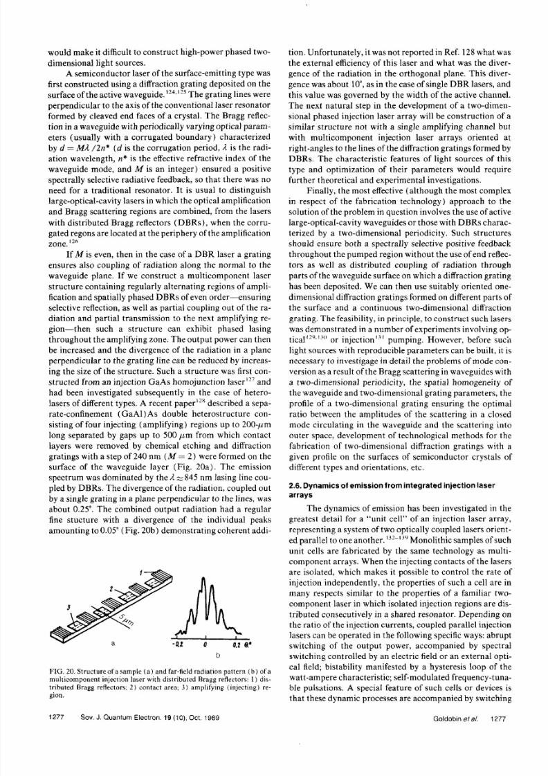
would make it difficult to construct high- power phased two-
dimensional light sources.
A semiconductor laser of the surface-emitting type was
first constructed using a diffraction grating deposited on the
surface of the active waveguide.'24
''25
The grating lines were
perpendicular to the axis of the conventional laser resonator
formed by cleaved end faces of a crystal. The Bragg reflec-
tion in a waveguide with periodically varying optical param-
eters (usually with a corrugated boundary) characterized
by d = MX /2n* (d is the corrugation period, λ is the radi-
ation wavelength, n* is the effective refractive index of the
waveguide mode, and Μ is an integer) ensured a positive
spectrally selective radiative feedback, so that there was no
need for a traditional resonator. It is usual to distinguish
large-optical- cavity lasers in which the optical amplification
and Bragg scattering regions are combined, from the lasers
with distributed Bragg reflectors (D BRs), when the corru-
gated regons are located at the periphery of the amplification
zone.12 6
If Μ is even, then in the case of a DBR laser a grating
ensures also coupling of radiation along the normal to the
waveguide plane. If we construct a multicomponent laser
structure containing regularly alternating regions of ampli-fication and spatially phased DBRs of even order—ensuring
selective reflection, as well as partial coupling out of the ra-
diation and partial transmission to the next amplifying re-
gion—then such a structure can exhibit phased lasing
throughout the amplifying zone. The output power can then
be increased and the divergence of the radiation in a plane
tion. Unfortunately, it was not reported in Ref. 128 what was
the external efficiency of th is laser and what was the diver-
gence of the radiation in the orthogonal plane. This diver-
gence was about 10° as in the case of single DBR lasers, and
this value was governed by the width of the active channel.The next natural step in the development of a two- dimen-
sional phased injection laser array will be construction of a
similar structure not with a single amplifying channel but
with multicomponent injection laser arrays oriented at
right- angles to the lines of the diffraction gratings formed by
DBRs. The characteristic features of light sources of this
type and optimization of their parameters would require
further theoret ical and experimental investigations.
Finally, the most effective (although the most complexin respect of the fabrication technology) approach to the
solution of the problem in question involves the use of active
large- optical- cavity waveguides or those with D BRs charac-
terized by a two- dimensional periodicity. Such structures
should ensure both a spectrally selective positive feedback
throughout the pumped region without the use of end reflec-
tors as well as distributed coupling of radiation through
parts of the waveguide surface on which a diffraction grating
has been deposited. We can then use suitably oriented one-dimensional diffraction gratings formed on different parts of
the surface and a con tinuous two-dimensional diffraction
grating. The feasibility, in principle, to construct such lasers
was demonstrated in a number of experiments involving op-
t ical '2 9 1 3
" or injection131
pumping. However, before such
light sources with reproducible parameters can be built, it is
8/6/2019 Phase-Locked Integrated Arrays of Injection Lasers Ch2
http://slidepdf.com/reader/full/phase-locked-integrated-arrays-of-injection-lasers-ch2 19/25
between different supermodes and a corresponding spatial
redistribution in the near- and far-field zones. A system of
two coupled parallel injection lasers with different resonator
lengths140
is characterized by a high spectral selectivity,
which ensures single- frequency lasing in a wide range of in-
jection currents. The dynamics of spectral tuning is analo-gous to that in lasers with consecutively arranged C
3
(cleaved- coupled- cavity) lasers. Similar active elements,
discussed in greater detail in a review in Ref. 141 are of prac-
tical interest for various kinds of optoelectronic data- han-
dling systems. It has been suggested that they could be used
as transmitters in fiber-optic communication lines, as logic
elements, etc.
Multicomponent injection laser arrays with a shared
contac t have dynamic characteristics of their integral output
power basically similar to the characteristics exhibited by
ordinary homogeneously excited injection lasers. Perturba-
tion theory is used in Ref. 142 to calculate the reaction of a
multicomponent system of coupled lasers to an alternating
perturbation of its steady state. An analytic solution is ob-
tained in the case of a two- component system. The ampli-
tude- frequency and frequency modulation characteristics
are qualitatively similar to the corresponding characteristics
of a single injection laser." The quan titative result dependsstrongly on the parameters representing coupling of the
components and the effective spectral broadening factor. An
experimental investigaiton of pulse amplitude modulation of
a seven- component array of (G aAl)As heterojunction la-
sers with separate confinement, grown on a profile of the
substrate, was reported in Ref. 143. Symmetric variat ion of
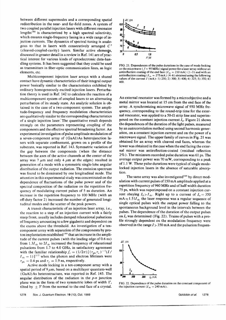
too
9»e
l
90
70
50
At , ps
0.5 1.0
P,W
F I G . 21. De pe nde nce s of the pulse dura t ions in th e case of m o d e locking
on the microwave ( / = 95 MH z) signal power for a laser array without an
antireflection coating of the end face ( /lh
= 210 mA) (1- 3) and with an
antireflection coating (7lh
= 275mA) (4-6) obta ined using the following
values of the cur re n t I (m A): 1) 250; 2) 300; 3) 400; 4) 325; 5) 350; 6)
400.
An external resonator was formed by a microobjective and a
metal mirror was located at 15 cm from the end face of the
array. A synchronizing microwave signal of 950 MH z fre-
quency, corresponding to the round- trip time for the exter-
nal resonator , was applied to a 50- Ω strip line and superim-
posed on the constant injection current Io. Figure 21 showsth e dependences of the durat ion of the light pulses, measured
by an autocorrelation method using second harmonic gener-
ation, on a constant injection current and on the power of a
microwave signal. The upper family of curves in F ig. 21 was
obtained for an array with cleaved end faces, whereas the
lower was obtained in the case when the end facing the exter-

8/6/2019 Phase-Locked Integrated Arrays of Injection Lasers Ch2
http://slidepdf.com/reader/full/phase-locked-integrated-arrays-of-injection-lasers-ch2 20/25
cy was 3- 5 G Hz. The peak power, calculated allowing for
the average power, reached 0.8 W, which was at least an
order of magnitude higher than the value expected from the
static watt- ampere characteristic for the same amplitude of
the modulating pulses. A theoretical analysis of such ampli-tude modulation was carried out by the authors of that paper
on the basis of the familiar system of rate equations relating
the phonon density to the density of nonequilibrium carriers
in an injection laser and using parameters typical of quan-
tum- well heterostructures.
I n many practical applications of phased injection laser
arrays the spatial dynamics plays a decisive role, i.e., a redis-
tribution in the near- and far-field zones as a result of ampli-
tude and modulation of the current is the dominant effect. Adetailed theory of these processes allowing for the character-
istic features of the mode composition in the case of arrays of
different type is not yet available. The results of the various
experimental investigations demonstrate the complexity and
variety of the transient processes which then occur. An im-
age- converter camera had been used to record the time de-
pendences of the radiation intensity of each of the compo-
nents of a ten- component array and of each of the three main
lobes of the angular distribution when an array was excitedby current pulses of 50 ns duration with a 0.6 ns leading
edge.147
A scanning avalanche photodiode and a sampling
oscilloscope (with a time resolution of 100 ps) were used144
to record the evolution of the far-field pattern of the radi-
ation emitted by a ten- component NDW array excited by
nanosecond current pulses with a leading edge of 1.0 ns. It
= t ins
Μ
F I G . 24. Evolut ion of the far-field radia t ion pat tern (obta ined for pulses
of 10 ns d u r a t i o n ) .
2.7 . The rma l p rob lems in he ope ra t i on of n jec t i on lase rar rays
A considerable thermal power is released during oper-ation of phased injection laser arrays in the most interesting
(from the practical point of view) case of cw lasing. A local
increase in the temperature alters the distribution of the ef-
fective refractive index in an array. This effect influences less
the operation of BDW arrays, whereas in the case of NDW
lasers it may affect strongly the mode composition of the

8/6/2019 Phase-Locked Integrated Arrays of Injection Lasers Ch2
http://slidepdf.com/reader/full/phase-locked-integrated-arrays-of-injection-lasers-ch2 21/25
«l- r ,oc/ w
ο
• ο
/ : , , , · ' • '. ΛΝ Ί 3 2 1 5 4 3 2 1
o . s
0 , 2
Ο
F I G . 26. Profile of the distribution of th e t e mpe ra ture rise on the heat -transfer surface and the difference between the t e mpe ra ture s of adjacent
c o m p o n e n t s when the electr ical power was 1 W (half of a symmet ric
distr ibution is shown) at th ecenter of a stripe conta c t ( Ο ) , at t he center of
a waveguide strip subjected to homogeneous pumpin g ( c o n t i n u o u s con-
tact ) ( · ) , the average value over the length of th e stripe conta c t ( | ) , and
over the length of the homogeneouslyp u m p e d waveguide ( Π ) : 1) ce n te r
of the array; 2) edge of the array; Ν is the laser diode n u m b e r .
I n an array of injection lasers the middle components
are under less favorable therm al conditions than the compo-
nents at the edges, where heat transfer is more effective. A
calculation of the temperature distribution on the surface of
a semiinfinite copper heat sink (the presence of which is
usually assumed, in injection laser models) and the differ-
ence between the temperatures of the adjacent components
of laser arrays with between 10 and 40 components, de-
scribed in Refs. 49 and 53, was made14 9
for the cw case (Fig.
perature variations between the separate components, in
spite of the fact of the somewhat strong heating of the grating
as a whole.
2.8 . Co n t r o l of he radiat ion emi t ted by njec t ion laser arrays
using ex te rna l opt i ca l dev ices
The limited space does not allow us to discuss in detail
non integral methods for phase- locked addition of the radi-
ation from injection lasers. We shall list here the main meth-
ods of such addition with the aid of external devices.
1. Use of a master single- mode laser em itting radiation
coupled into a grating.15 0
~15 5
In this case the tuning of the
master laser radiat ion to the frequency of the lowest super-
mode of an array can ensure a stable emission of the super-
mode.
2. The use of an external resonator for the correction of
spectral and spatial characteristics of the radiation emitted
by laser arrays is practiced.15 6
~16 1
Stable lasing in the form of
the fundamental supermode is then achieved as a result of
selective feedback (the use of a diffraction grating or of
Fabry- Perot etalons'5*) or supermodes may be selected by
means of spatial filters.157160161
3. Use of phase correction of the wavefront in the far-
field zone16 2
"16 4
in order to achieve a single- lobe angular dis-
tribution of the output radiation.
4. Coherent addition of laser radiation in multimode
waveguides can also be achieved.
We shall now consider the methods described above in
somewhat greater detail.

8/6/2019 Phase-Locked Integrated Arrays of Injection Lasers Ch2
http://slidepdf.com/reader/full/phase-locked-integrated-arrays-of-injection-lasers-ch2 22/25
These properties make it possible to use multimode
waveguides in a variety of systems for coherent addition of
signals from semiconductor laser oscillators and ampli-
fiers.167
An experimental demonstration of the possibility of
coupling two injection homojunction lasers by a planar mul-
timode waveguide was ma de16 7
by the transfer of the image
of a light- emitting region of a master oscillator to the entry
face of a second laser diode used as a regenerat ive amplifier.
A regenerative gain of about 10 was attained in a hollow
metal waveguide with a diameter 2a = 62 μη ι; the wave-
length was λ = 0.84/ / m and the position of a cophasal sec-
tion was AZC
—4.6 mm.
An analysis was also made of the operation of a pile of
injection lasers located in a multimode waveguide at replica-
tion distances in such a way tha t a single light- emitting sys-
tem was formed and the coherence of the generation of oscil-
lations was ensured by a shared master oscillator or a local
reflector, which was also located at a replication distance.
There is an analogy between the transfer of images
along a mult imode waveguide and the Talbot effect168
in
which images are reconstructed at a certain distance from a
plane carrying a regular array of identical luminous objects.
I n the waveguide case the role of this array is played by
multiple reflections of the initial image by the waveguide
walls. This leads to an analogy between a successful experi-
mentl 6g
involving coherent addit ion of oscillations, genera-
ted in several carbon dioxide lasers emitting at 10.6// m, with
th e aid of exit mirrors located at the positions in a Talbot
with flashlamps or LE Ds) angular distribution of the injec-
tion laser radiat ion make it possible to increase considerably
th e efficiency of solid- state lasers and to reduce their dimen-
sions. Semiconductor laser arrays are used more and more
frequently as such pump sources. Phased addition of the ra-
diation from the individual components of an array is not
essential, but what is important is the density of the optical
power per unit emitting area and the total optical power.
I t was reported in Ref. 171 that a solid- state YAG:N d
laser with an ou tput power up to 80 mW was constructed; it
was pumped by a laser array generating continuously 220
mW with an external efficiency of 22%. The overall effi-
ciency of the solid- state laser was 8%, which is at present a
record value.
High- power pum p sources for solid- state lasers can be
in the form of the same monolithic laser arrays that were
described in the preceding sections, but the number of com-
ponents can be larger. It was reported in Ref. 172 that an
optical output power of 11 W was obtained from a laser
source emitting long (150- /zs) pulses with duration of the
same order as the lifetime of the excited states in neody-
mium- doped garnet crystals. This source was a crystal
where in a region of 1 cm size there were 20 phased 10-
component NDW arrays separated by a spacing of 0.5 mm
an d similar to those described in Ref. 50. The presence of
extended absorbing regions between the individual arrays
prevented amplification of spontaneous radiation propagat-
ing at right- angles to the stripe contacts and at angles (rela-
tive to the mirrors) greater than the total- internal- reflection

8/6/2019 Phase-Locked Integrated Arrays of Injection Lasers Ch2
http://slidepdf.com/reader/full/phase-locked-integrated-arrays-of-injection-lasers-ch2 23/25
result was obtained by ensuring equality of the laser radi-
ation wavelengths and the stability of their phases with time.
The same principle could be used to con struct a two- dimen-
sional laser array.
The proposed laser array with a random distribution of
phases can in our opinion be also useful in a number of otherpractical applications. Experimental studies are essential to
confirm the theoret ical results predicted in Ref. 173 and it
would be necessary to optimize the design specifically to fit
semiconductor structures.
These results demonstrate extensive opportunities that
th e use of laser arrays with random (nonlocked) distribu-
tion of phases can provide. The extremely high output pow-
ers in combinat ion with high efficiencies and small dimen-
sions of such arrays make them suitable not only forpumping solid- state lasers, but also in lidar and optical illu-
mina t ion systems, high- speed ph otography, and other prac-
tical applications.
CONCLUSIONS
I t follows from our review that in the last decade of
intensive research on monolithic injection laser ar rays, both
phased and noncoherent, has provided an understanding to
what extent the various physical properties and parametersinfluence the technical characteristics of such arrays. The
focus in the technology of ordinary injection lasers has been
accompanied by improvements in the array structure. The
o u tp u t power now available (~0.5 W for a diffraction- limit
divergence of the radiation from phased arrays and ~ 10 W
in the form of cw or quasi-cw radiation in th e case of nonco-
"E . D. H inkley, J. R. Lesh, and R. T . Menzies, Laser F ocus 21, N o. 2, 78(1985).
7J . Katz, I E E E Commun . Mag. 21, N o. 6, 20 (1983).
"A. E. Bell, Laser Focus 19, No . 8,61 (1983) ; No . 9, 125 (1983) .9L . Holmes, Laser F o c u s / E l e c t r o - O p t . 21, No. 6, 112 (1985).
'"Yu. A. Bykovskii, Ν . Ν . Evtikhiev, V. A. Elkhov, and A. I. Larkin
Kvantovaya Elektro n. (Moscow) 2, 1074 (1975) [Sov. J. Qua ntu m
Ele c t ron . 5, 587 (1975)].
"A. I. Zolotarev, S. P. Kalashnikov, V. A. Kon drat'e v, and V. N . Moro
zov, Tr. Fiz. In st. Akad. N auk SSSR 185, 90 (1987).I 2
N . Holonyak Jr., R. M. Kolbas, R. D. Dupu is, and P. D . Dapkus, I E E E
J . Quantum Electron. QE-16, 170 (1980).I 3
G . L. Harn agel, D. R. Scifres, H. H . Kung, D . F. Welch, P. S. Crossan d R. D . Burnham, Electron. Lett. 22, 605 (1986).
I 4G . L. H arnagel, P. S. Cross, D. R. Scifres, D. F . Welch, C. R. LennonD . P. Worland, an dR . D. Burnham , Appl. Ph ys. Lett. 49, 1418 (1986)
I 5M . Ettenberg, Laser Focus 21, N o. 5, 86 (1985).
I 6L . Figueroa, Laser Focus/ Electro- Opt.23, No . 4, 18 (1987).
I 7D . Scifres, R. D . Burn ham , and W. Streifer, Appl. P hys. Lett. 33, 101(1978).
"*V I. Malakhova, Yu. A. Tambiev, and S. D . Yakubovich, KvantovayEle kt ron . (Mo scow) 8, 2216 (1981) [Sov. J. Quant um Electron. 111351 (1981)].
I 9D . F. Welch, D . R. Scifres, P. S. Cross, Η . Η . Kung, W. Streifer, etal
Appl. Phys. Lett. 47, 1134 (1985).2 0
P . G. Eliseev, Itogi Nau ki Tekh. Ser. Ra diotekh. 14, Part I ( 1978).2' D. R. Scifres, W. Streifer, an d R. D . Burnham , I E E E J. Qu antum Elect ron . QE-15, 917 (1979).
2 2K . Otsuka, Electron . Lett. 19, 723 (1983) .
2 3C . H. Henry, in Semiconductors and Semimetals, Vol. 22, Lightwav
Communications Technology(ed. by W. T. Tsang),
Part B, Semicon
ductor Injection Lasers I, Academic P ress, New York (1985), p . 153.2 4
J . K. Butler, D. E. Ackley, and D. Botez, Appl. Phys. Lett. 44, 29(1984).
" J . K. Butler, D. E. Ackley, an d M. Etten berg, I E E E J. Quan tum Elect ron . QE- 21, 458 (1985).
2 6E . Kapon, J. Katz, and A. Yariv, Opt. Lett. 9, 125 (1984).
"A. Ha rdy and W. Streifer, Op t. Lett. 10, 335 (1985).28
A. Hardy and W. Streifer, J. Lightwave Techn ol. LT-4, 90 (1986).

8/6/2019 Phase-Locked Integrated Arrays of Injection Lasers Ch2
http://slidepdf.com/reader/full/phase-locked-integrated-arrays-of-injection-lasers-ch2 24/25
5 5D . Botez and J. C. Conn olly, Appl . P hys. Lett . 43, 1096 (1983) .
5 6H . Tem kin, R. D. D upuis, R. A. Logan, and J. P. Van der Ziel, Appl .
Ph ys. Lett . 44 , 473 (1984) .5 7
T . L. Paol i , W. Streifer , an d R. D . Burn ham , Appl . Ph ys. Lett . 45, 217
(1984 ) .5 8
E . Kap on, J. Katz, S . M argal it , and A. Yariv, Appl. P hys. Lett . 45, 600
(1984 ) .59Y. Twu, A. D ienes, S . Wang, and J. R. Whinnery, Appl . Ph ys. Lett . 45,709 (1984) .
W'S . M ukai, C. L indsey, J . K a tz , E . Kapon , et al, Appl. Phys. Lett . 45,834 (1984) .
6 1E . Kap on, L . T. Lu, Z. Rav-N oy, M. Li , S. Margal i t , and A. Yariv,
Appl. P hys. Lett . 46 , 136 (19 85) .6 2
H . Tem kin, R. A. Logan, J. P. Van der Ziel, C. L . Reynolds, Jr . , and S.M . Thara ldsen, Appl . Phys. Lett . 46 , 465 (1985) .
6' Ρ . G avri lovic, K. M eehan, J. E. Epler, etal., Appl. P hys. Lett . 46, 857
(1985) .M
N . K. D utta , L . A. Koszi , B. P. Segner, D . C. Craft , and S. G . N aph oltz ,
Appl . P hys. Lett . 46, 803 (1985) .6 5N . Kan eno, T. Kadowski, J . Ohsawa, et al, Electron. Lett . 21, 780
(1985) .6 6
M . M atsum oto, M. Taneya, S. Matsui , S . Yano, and T. H ijikata, J .Appl . Ph ys. 58, 2783 (1 985) .
6 7D . F . Welch, P . S. Cross, D . R. Scifres, G . Harn agel , et al, Elec t ron .Le t t . 22, 464 (1 986) .
6 8C . A . Z m u d z i n sk i, L . J . M a w st , Μ . Ε . G i ve n s, etal., Appl. Phys. Lett .48 , 1 4 2 4 ( 1 9 8 6 ) .
6 9G . C. D ente, K. A. Wilson, T . C. Salvi , and D . Depatie , Appl . P hys.Lett . 51, 9 (1 987) .
™N. W. C arlson, V. J. M asin , M . Lurie, B. Goldstein , and G . A. Evans,
Appl . Ph ys. Lett . 51, 643 (1 987) .7IJ . P. H ohim er, G . R. H adley, and A. Owyoung, Appl . P hys. Lett . 48,1504 (1986) .
72J . R. Andrews, T. L . Pao l i , W. Streifer , and R . D . Burn ham , J. App l .Ph ys. 58, 2777 ( 1985) .
" D . R. Scifres, W. Streifer , an d R. D . Burnham , Appl . P hys. Lett . 33,702(1978) .
7 4J . Kat z, E. Kap on, C. P. Lindsey, S . Margal i t , U. Shreter, and A. Yariv,
Appl. P hys. Lett . 43, 521 (1 983) .
"" ' D . R. Scifres, W. Streifer , an d R. D . Burnham , US Patent N o. 4 255717, filed Oc tober 30, 1978; publ. Mar ch 10, 1981.
1("K . L. Chen and S. Wang, E lectron. Lett . 21, 347 (1985) .
") 2
M . Taneya, M . Matsum oto, S. M atsui , S . Yano, and T . Hijikata, Appl .Ph ys. Lett . 47, 341 ( 1985) .
IO3W. Streifer, P . S. C ross, D . F . Welch, an d D . R. Scifres, Appl. P hys.
Lett . 49, 58 (1986) ."I 4
K . L. Chen and S. Wang, Electron . Lett . 22, 644 (1 986) ."
)5W. Streifer , D . F . Welch, P. S . Cross, and D . R. Scifres, I EE E J. Quan -tu m Elec t ron . QE - 23 , 74 4 ( 1987) .
"> 6
R . F . H a r r in g t o n , Time-Harmonic Electromagnetic Fields, M c G r a w -H il l, N ew York (196 1) .
I O 7D . F . Welch, P . Cross, D. Scifres, W. Streifer , an d R. D . Burn ham ,Ele c t ron . Lett . 22, 293 (1986) .
"I 8
D . F . Welch, P. S . Cross, D. R. Scifres, W. Streifer , and R. D . Burn ham ,Appl . Ph ys. Lett . 49, 1632 (1986 ) .
"19
A. E. Bazarov, I . S . G oldobin, P. G. El iseev, O . A. Kobilzhan ov, etal,
Kvantovaya E lektron. (M oscow )14 , 874 (1987) [Sov. J. Qu antu m
Ele c t ron . 17 ,551 (1987) ] .' " Ά . P. Bogatov, I . S. Goldobin, P. G. El iseev, G . T. Pak, et al, Prepr in tN o. 221 [ in R ussian], L ebedev Ph ysics In sti tute, Academy of Sciencesof the USSR, Moscow (1987) .
" Ί . S . G o ldob in , G . T . Pak , T . V. P e t rakova , Τ . Ν . Pushk ina , et al,Kvant ovaya Elektron. (M oscow) 14 , 1737 (1987) [Sov. J. Qu antu mEle c t ron . 17, 1108 (1987)] .
"2D . F . Welch, W. Streifer , P. S . Cross, and D . R. Scifres, IE EE J. Quan-tu m Elec t ron . QE - 23 , 752 (1987) .
1I 3J . M. F inlan, Appl . Op t. 25, 1373 (1 986) .
"4W. F . Kosonocky , R. H. Com ely, and I . J . Hegy i, I EE E J. Quan tumEle c t ron . QE-4 , 176 (196 8) .
"5
J . Katz , N . Bar- Charm, S. M arga l it , and A. Yariv, J. Appl. Phys. 51.4038 (1980) .
"6S . U chiyam a and K. Iga, Electron. Lett . 21, 162 ( 1985) .
"7S . U chiyama, Y. Ohm ae, S. Shimizu, and K . Iga, Technical D igest ofP a p e r s presented at F if th I nter n. Conf. on Integrated Optics and Opti -cal F ibre Com m unication and Eleventh Euro pean Conf. on OpticalC o m m u n i c a t i o n , Venice, 1985, Vol . 1, publ. by Ist i tuto In t . C om m uni-caz ioni , G enoa (1985) , p . 6 23 .
" * Z . L. Liau and J. N. Walpole, App l . P hys. Lett . 46 , 115 (1 985) .

8/6/2019 Phase-Locked Integrated Arrays of Injection Lasers Ch2
http://slidepdf.com/reader/full/phase-locked-integrated-arrays-of-injection-lasers-ch2 25/25
I4- R . J. Lang and A. Yariv, I E E E J . Q u a n t u m E l e ct r o n . QE -21 , 1683
(1985) .I 4 3
P . L . F u h r and F . M. Davidson, Opt. Eng. 25, 1241 (1986) .I 4 4
K . A. F orrest and J. B. Abshire, I E E E J . Q u a n t u m E l e c tr o n . QE - 23,
1287 (1987) .I 4 5
J . P. van der Ziel , H. Temkin, R. D . D upu is, and R. M . M ikulyak,Appl . Ph ys. Lett . 44 , 357 (198 3) .
' • * "} . P. van der Ziel , H . Tem kin, R. A. Logan, and R. D . D upu is, I E E E J .Q u a n t u m Elec t ron . QE -20 , 1236 (1984) .
14 7R . A. E l l io t , R . K. D eF reez , T . L . Pao l i , R . D . Burnham, and W.
Streifer, I E E E J . Quan tum E lec t ron . QE - 2 1 , 598 (1985) .l 4 1 i
J . K a t z , I E E E J . Quan tum E lec t ron . QE - 21, 1854 (1985) .14 9
E . M . G a r m i r e a n d Μ . Τ . Ta vi s, I E E E J . Q u a n t u m E l e c tr o n . QE -20 ,
1277 (1984) .15<)
W. W. Chow, I E E E J . Q u a n t u m E l e c tr o n . QE - 22, 655 (1986) .15
' M . K. C hun , T . L . Whi tman , an d D . G. Soenksen , App l . Op t . 26 , 4 518(1987) .
I 5 2L . G oldberg and J. F . Weller , Electro n. Lett . 22 , 858 (1986) .
' " L . G oldberg and J. F . Weller , Appl . P hys. Lett . 50, 1713 (1987) .I 5 4 H . H em m ati and J. B. Abshire, App l . P hys. Lett . 50, 638 (1987) .I 5 5
L . G oldberg, H . F . T ay lo r , and I . F . Weller, I E E E J . Quan tum E lec-t ron . QE -22 , 513 (1986) .
i 5 6D . L. Begley, D . Mar t in , B. Vivian, and R. R . Rice, Appl . O pt. 25, 4007
(1986 ) .I5 7
A. H ardy, W. Streifer , an d M . Osinski, App l . P hys. Lett . 49, 185
(1986 ) .Ι 5
Ή . H emm at i , App l . Phys . L e t t . 51 , 224 (1987) .I 5
"L . G oldberg and J. F . Weller, Appl . P hys. Lett . 51, 871 (1987) .
16 0C . J. C hang- H asnain, J. Berger, D . R. Scifres, et al. , Appl. Phys. Lett
50, 1465 (1987) .I 6 I
J . Yaeli, W. Streifer, D . R. Scifres, et al., Appl. Phys. Lett . 47, 89(1985) .
I 6 2J . R. H eidel, R. R. Rice, and H. R. Appelman, I E E E J . Quan tum E lec -t ron . QE - 22, 749 (1986) .
1 MN . W. C arlson, J. K. Butler , and V. J. M asin , Electro n. Lett . 22 , 1327
(1986 ) .I 6 4
J . R. Leger, G. J. Swanson, and M . Holz, Appl . P hys. Lett . 50, 1044
(1987) .I 6 5
L . A. R ivlin an d V. S. Shil 'dyaev, I zv. Vyssh. U chebn. Zaved. R adiofiz
11 ,572 (196 8) .I 6 6
E . E. G rigor 'eva and A. T. Semenov, Kvantovaya E lektron. (M oscow)
5, 1877 (1978) [Sov. J. Qu antu m Electron. 8, 1063 ( 197 8) ] .' " L . A. R ivlin, A. B. U its, and V. S. Shil 'dyaev, Izv. Vyssh. U c h e b n
Zaved. Radiofiz. 12 , 1586 (1969) .I 6
"H . F . Talbot, Londo n Edinb. Dublin Ph ilos. Mag. 9 , 401 (1836) .'""V. V. Antyukhov, A. F . G lova, O. R. Kach urin , etal, Pis 'm a Z h . Eksp
T eor . F iz . 4 4 , 63 (1986 ) [ JET P L e t t . 4 4 , 78 (198 6 ) ] .I7 "L . A. Rivlin , Kvantovaya E lektron. (M oscow) N o. 5( 11) , 46 (1972)
[Sov. J . Quan tum E lec t ron . 2, 4 27 (1973 ) ] .m
G . L. H arnagel , P. S. Cross, D. R. Scifres, and D . P. Worland, E lectron.Le t t . 22 , 231 (1986) .
I 7 2D . L. Sipes, Appl. Phys. Lett. 47, 74 (1985).
1 7 3D . R. Suhre, Appl . O pt. 25, 3916 ( 1986) .
Translated by A. Tybulewicz