phasuite: an automated hazop analysis tool for … · checklist, hazard and operability (hazop),...
TRANSCRIPT

PHASUITE: AN AUTOMATED HAZOP ANALYSIS TOOLFOR CHEMICAL PROCESSES
Part I: Knowledge Engineering Framework
C. ZHAO, M. BHUSHAN and V. VENKATASUBRAMANIAN�
Laboratory for Intelligent Process Systems, School of Chemical Engineering, Purdue University, West Lafayette, IN, USA
Hazard and operability analysis (HAZOP) is widely used in process hazard analysis ofchemical processes. But it is time and effort consuming. To aid human experts inconducting HAZOP analysis in a more thorough and systematic way, a software
system (PHASuite) for automated HAZOP analysis has been developed. PHASuite cangreatly increase the efficiency of the HAZOP analysis, support best analysis practices, andprovide foundation for reuse of the safety knowledge generated from the analysis. Giventhe knowledge intensive nature of HAZOP analysis, a knowledge engineering frameworkwas developed. From the point of view of functionality, the framework consists of fourmain parts: information sharing, representation, knowledge base and reasoning engine. Ontol-ogy based information sharing schemes are developed to share process information and resultswith other systems. Coloured Petri Nets based representation, created from process infor-mation, is used to represent chemical processes as well as the methodology for HAZOP analy-sis. In this framework, a process is decomposed into two abstraction levels, operation leveland equipment level, which are bridged using functional representation. Analysis is carriedout on both the levels. Knowledge used in this system is stored in models. Case-based tech-niques are adopted for knowledge management. Knowledge base is stored externally in struc-tured databases. A two-level, two-layer reasoning engine has been designed to operate on thePetri Nets representation of the process using the knowledge base to perform HAZOPanalysis.
Keywords: automated HAZOP analysis; knowledge engineering; coloured Petri Nets;functional representation; model-based reasoning; case-based reasoning.
INTRODUCTION
Safety is an important issue in process design and operationin chemical industry. It is even more critical for modernchemical manufacturing processes, which are either oper-ated under extreme conditions to achieve maximum econ-omic profit, or are highly flexible, such as the specialtychemical or pharmaceutical processes. The importance ofsafety analysis in process operation is well recognizedafter occurrence of several tragic accidents that couldhave been avoided by adequate process safety analysis(Kletz, 1999). As a result, OSHA set the standard for pro-cess safety management (Title 29 CFR 1910.119), whichrequires the use of a process hazard analysis (PHA)technique for the identification of process hazards. It is
estimated that 25 000 plant sites in US are covered by theOSHA standard.
Process Hazard Analysis
To ensure safe operation, process hazard analysis (PHA)is very important to proactively identify the potential safetyproblems and recommend possible solutions. There are sev-eral techniques for performing PHA, including What-If,Checklist, Hazard and Operability (HAZOP), FailureModes and Effects Analysis and Fault Tree Analysis. Acomparison of these methods and review of efforts in auto-mating Checklist, FMEA, and Fault Tree Analysis, can befound in Vaidhyanathan (1995).
HAZOP is the method for identifying hazards and pro-blems that prevent efficient and safe operation. It is easyto learn and use, and can be easily adapted to almost allthe operations that are carried out within process industries.Hence it is widely accepted as the method for conductingPHA studies for chemical processes. A history of
�Correspondence to: Professor V. Venkatasubramanian, Laboratory forIntelligent Process Systems, School of Chemical Engineering, PurdueUniversity, West Lafayette, IN 47907, USA.E-mail: [email protected]
509
0957–5820/05/$30.00+0.00# 2005 Institution of Chemical Engineers
www.icheme.org/journals Trans IChemE, Part B, November 2005doi: 10.1205/psep.04055 Process Safety and Environmental Protection, 83(B6): 509–532
HAZOP analysis can be found in Kletz (1999). HAZOPstudies are usually carried out by a team consisting offour to five members, who are experts on different aspectsof the process, led by a team leader. The study requires theteam to have detailed knowledge of the way the plant isintended to function. A typical team may consist of eachof the following members: a chemical engineer, mechanicalengineer, R&D chemist, production manager, and may be aninstrumentation engineer and so on.After defining the objective and scope of the study,
selecting the team, and preparing the required documents,the study is carried out. Process is decomposed into man-ageable study units. Guidewords, including NONE, PARTOF, MORE OF, MORE THAN, LESS OF, OTHERTHAN, are applied to various aspects of the design intentto generate potential deviations. The effects of these devi-ations on the process or operation are analysed. The devi-ations resulting in hazardous or significant consequencesare recorded along with the possible causes, needed actions,andquestions/comments/recommendations.Detaileddescrip-tions of the analysis procedure with illustrative exampleshave been given by CCPS (1985) and Kletz (1999). HAZOPanalysis can be used in different stages of a process, includingat design phase for early checking for major hazards, at designfreeze phase, at pre start-up, prior to plant modifications, priorto taking a plant out of service and so on. The possiblevariances can be found in Knowlton (1981).
Automated HAZOP Analysis
HAZOP is, however, very time-consuming. According toone estimate (Freeman, 1992), for a process with eightP&ID consisting of simple, standard, complex and verycomplex drawings, a team of five people led by an experi-enced team leader, the completion of the HAZOP analysisneeds 441 man hours, and the overall elapsed time is about8 weeks. So an automated tool is definitely helpful. But afully automated HAZOP analysis tool, which can totallyreplace the human team, is very difficult and nearly imposs-ible to realize in the near future. The difficulties lie in thefact that the highly flexible reasoning mechanism andknowledge structure of human experts cannot be effectivelysimulated by computer systems. Nevertheless, as Kletz(1999) pointed out, an automated HAZOP analysis toolcan certainly be used as an aid for human experts. Notonly can automated HAZOP analysis tool, like PHASuite,help in making PHA study more thorough, systematic andconsistent, improving the quality of the review, reducingthe time and effort of the team, and documenting resultsfor regulatory compliance, but can also be used in trainingnew operators and for online abnormal situation manage-ment. The key functionality of automated HAZOP analysistool is its reasoning capability. Most of the commer-cially available HAZOP tools, such as PHAWorks, andPHAPro, can be considered as documentation tools whichprovide workflow support for HAZOP analysis. Eventhough library of possible hazardous are usually provided,these tools do not use them to carry out reasoningautonomously.Several attempts for automating HAZOP analysis have
been made in the past two decades. Parmar and Lees(1987) represented the knowledge required for propagatingfaults in each process unit using qualitative propagation
equations and event statements for initiation and termin-ation of faults. The causes are generated by searching forthe initial events and the consequences by searching theterminal events. However, the analysis is not completesince the causes and consequences are not propagated.The system is also very limited since the knowledge washardwired for the given process. Waters and Ponton(1989) attempted to use a quasi-steady state qualitativesimulation approach to automate HAZOP analysis. Theyfound the approach to be highly combinatorial, thusrestricting its practical usefulness. Karvonen et al. (1990)developed a rule-based expert system prototype using theKEE shell. The system’s knowledge base consisted of thestructure of the process and rules for searching causesand consequences. The generality of the system is limiteddue to the structure of the rules dependent on the processstructure. Catino and Ungar (1995) developed a prototypeHAZOP identification system which works by exhaustivelylocating possible faults, automatically building qualitativeprocess models, simulating them and checking for hazards.This approach starts with faults whereas the HAZOP analy-sis starts with process deviations. Also this approach is toofine-grained for industrial scale process hazards reviews. Adetailed survey of the literature on intelligent systems forHAZOP analysis can be found in Venkatasubramanianet al. (2000). Recently, Kang and Yoon (2001) proposedto use multiple models consisting of the unit functionmodel, the unit behaviour model, the process structuremodel and the process material model to describe thechem-ical processes from a safety-oriented point of view.
Most of the above approaches to automated hazardsanalysis were demonstrated on small-scale processes or aca-demic prototypes. Venkatasubramanian and coworkers havebeen working extensively in this area, and the systems devel-oped by their group have been applied to a wide-variety ofindustrial scale process plants. Vaidhyanathan and Venkata-subramanian (1996) developed a model-based frameworkfor continuous processes in which the knowledge requiredto perform HAZOP analysis is divided into process-specificand process-generic components. Process-generic knowl-edge consists of signed digraph models of the processunits. Based on the framework an expert system HazopEx-pert was developed. Srinivasan and Venkatasubramanian(1998) adopted Petri Net representation and SDG basedHAZOP analysis for batch processes, and developed thesystem BatchHazopExpert. At the same time, iTOPS, anintelligent tool for operating procedure synthesis wasdeveloped by Viswanathan et al. (1998). Since the operat-ing procedure synthesis and safety analysis share a lot ofinformation, a scheme for integrating iTOPS and BatchHa-zopExpert (BHE) was proposed by Zhao et al. (2000). Allthe above systems were developed in G2, an expert devel-opment shell (Gensym, 1997).
Although the above systems can be used to demonstratethe proposed methodologies for automating HAZOP analy-sis, they have some severe drawbacks, the important onesbeing:
(1) Most of the earlier attempts have focused on thereasoning methodologies. Issues regarding knowledgerepresentation, storage and management are not suffi-ciently addressed, and this leads to poor scalability ofthose systems.
Trans IChemE, Part B, Process Safety and Environmental Protection, 2005, 83(B6): 509–532
510 ZHAO et al.

(2) All the systems are only prototypes developed with theaim of demonstrating different ideas. Most of themwere developed in G2 or other expert shells, whichare good for prototyping, but have severe limitationsfor further development in terms of portability, scal-ability, and computational speed.
(3) Information sharing with other software systems is notaddressed.
(4) Among the systems developed at LIPS laboratory,HazopExpert and BatchHazopExpert share a lot ofsimilarity in functionality and structure, but they areimplemented as two separate systems.
(5) The integration between different systems is not welladdressed. The integration of iTOPS and BatchHazo-pExpert is a straightforward translation betweenobjects, which is time consuming and confusing.
The goal of this work is to develop PHASuite, as a highquality full-scale software system for automated HAZOPanalysis, to address abovementioned issues with previoussystems. PHASuite is a knowledge-based system, reasoningand analysing on chemical processes. The knowledge con-sists of models as well as experience related to processsafety.From the functionality point of view, PHASuite consists
of five main components, as illustrated in Figure 1. Infor-mation necessary for the analysis is first input to thesystem. In order to enable the computer program to analysethe process, the information is then transformed to a proper
representation suitable for automated analysis. Knowledgefor safety analysis, probably wrapped in models, is usedto model the process. Reasoning engine, consisting of thecontrol knowledge which uses the knowledge to performanalysis on the representation of the process, is theninvoked. The results generated from analysis are thenreviewed by the user through results management facilities.Automated HAZOP analysis is a very difficult task due tothe complex knowledge structure, flexible analysis depth,sophisticated user interaction, and requirement for learningthrough experience. The main difficulties of automatedHAZOP analysis are related to:
. Representation of process specific information, i.e., oper-ating procedures, P&ID and so on, which should be suit-able for HAZOP analysis.
. Representation of process generic information, i.e.,different kinds of knowledge for operation and equip-ments, representation of experience and knowledgeacquisition.
. Reasoning methodologies to apply knowledge on therepresentation of the process to generate analysis results.
Development of PHASuite is divided into two steps. Thefirst step is to design a knowledge engineering frameworkfor automated HAZOP analysis using various artificialintelligence techniques and the second step involves usingappropriate software engineering techniques to implementthe system. Accordingly, this paper is divided into twoparts. The first part focuses on the conceptual design ofthe system, i.e., the knowledge engineering frameworkbehind the system. And the second part concentrates onthe implementation guidelines and uses an industrial casestudy of a pharmaceutical process to illustrate the applica-bility and procedure of using PHASuite to assist humanexperts in HAZOP analysis.
Major components of the proposed knowledge engineer-ing framework for PHASuite are discussed in the rest ofthis part of the paper. The next section presents the ontol-ogies used in this work in order to develop the system in anopen way and to share information with other software sys-tems. Knowledge representation, storage, management andacquisition issues are addressed in the third section.Reasoning methodologies are discussed in the fourthsection.
ONTOLOGY BASED INFORMATION SHARING
Ontology
To be successful, an automated HAZOP system shouldbe constructed based on an open architecture, in whichknowledge is explicitly represented and information isshared among different systems. Ontologies are the basisof such an open architecture and have an important rolein the information sharing schemes presented in the knowl-edge engineering framework.
With the development of technology, software systemshave been developed for different areas as well as differentparts of the same area by different people and organiz-ations. Each of them uses different jargon. The way toenable better communication between people, organiz-ations and software, is to come to a shared understandingby reducing or eliminating conceptual and terminologicalFigure 1. Main issues on automated HAZOP system.
Trans IChemE, Part B, Process Safety and Environmental Protection, 2005, 83(B6): 509–532
PHASUITE: PART I 511

confusion. As pointed out in Uschold and Gruninger (1996),such an understanding can serve as a unified framework forthe different viewpoints, and can help to achieve (1) bettercommunication between people, and (2) inter-operabilityamong systems. The latter is achieved by translating betweendifferent models, paradigms, languages and software tools.The shared understanding is the basis for a formal encodingof the important entities, attributes, processes and their inter-relationships in the domain of interest. This formal represen-tation may be a shared component that is reusable in a soft-ware system. Automation of consistency checking ispossible and ensures the reliability of translation. In thispaper, ontology is defined as an explicit specification of aconceptualization (Gruber, 1993).An important motivation for ontologies is to integrate
models of different domains into a coherent framework.Ontologies are used as inter-lingua for the purpose ofinter-operability. In this work, the design of ontologies fol-lows the steps discussed above. The main purpose for devel-oping the ontologies is to use it as inter-lingua for externalinter-operability between PHASuite and other software sys-tems, and for internal inter-operability among components inPHASuite as well. The language used to define the ontolo-gies is currently informal, i.e., mostly are defined in naturallanguage. Although this kind of definition is sufficient forcurrent implementation, definitions created using moreformal language are desired for further implementation.Using KSL Ontology Server (Farquhar et al., 1995), whichis based on ontolingua, a mechanism for writing ontologiesin a canonical format, seems to be promising.
Information Sharing Scheme for PHASuite
Process safety analysis is an information intensive pro-cess. Large amount of information about different aspectsfrom different sources is necessary for analysis. The mainrequired information can be divided into four types:material, P&ID, chemistry and operating procedures.Most of the information is very basic and would be requiredfor specifying a process and hence would probably beavailable in formats used for other purposes. Re-enteringthat information into PHASuite can be time-consumingand error-prone. Thus the capability of information sharingwith other information sources or providers is very crucialfor successful deployment of PHASuite. The best way forinformation sharing is to share the ontologies among
different information sources. It is, however, not the casecurrently since the common ontologies do not exist andall the systems have been developed without the guidanceof the common ontologies. So the basic scheme appliedin PHASuite consists of two steps as illustrated inFigure 2. The first step is to access the informationsource and translate the required information into aformat suitable for PHASuite. This transformation isguided by a dictionary created from the ontologies definedfor PHASuite. Interface storage is constructed to store thistranslated information. The second step is to generate therun-time file from the interface storage. The following sec-tions demonstrate this scheme using examples of sharingoperating procedure information with Batch Plus andsafety analysis results with PHAPro. Approaches forusing this methodology for sharing information withMSDS and P&ID are also proposed and discussed.
Sharing operation information with Batch PlusFor the operation related information, we need concepts
for representing operating procedures, operating conditions,and parameters. The hierarchical level of ISA-S88.01standard, which consists of procedure, unit procedure,operation, and phase, is followed in this work (ANSI/ISA-S88.01, 1995). To specify information related tooperating procedure, parameters and operating conditionsare also needed. Examples of parameter include ‘Fraction’and ‘Method’ in Transfer operation. Examples of operatingconditions include temperature, pressure, and time of theoperation. Definition of process chemistry is straightfor-ward and can be divided into reaction and separation. Areaction is specified by reaction type, reactants, products,excessive reactants, inhibitors, catalysts and solvents. Aseparation is specified by input materials, names of differ-ent phases, and materials involved in each phase. Equip-ment is specified by design properties, such as designtemperature, design pressure and design capacity, as wellas some structural specifications including whether theequipment has a jacket and so on.
Batch Plus is a product from Aspen Technology Inc.(2000). As a batch simulation tool, it needs informationabout the operating procedures, equipment and some prop-erties of materials. Most of this information is also necess-ary for carrying out safety analysis. Thus it is very usefulfor PHASuite to share information with Batch Plus. Toachieve this, dictionaries are designed based on the
Figure 2. Information sharing scheme in PHASuite.
Trans IChemE, Part B, Process Safety and Environmental Protection, 2005, 83(B6): 509–532
512 ZHAO et al.

ontologies defined in PHASuite for different levels of oper-ations, equipment, and material. The dictionary includescorresponding operation name from PHASuite for eachoperation in Batch Plus, for example, OperationHoldForBlockOperation corresponds to Age, and OperationClean-VesselForBlockOperation corresponds to Clean in BatchPlus. The dictionary also includes mapping for each par-ameter in each operation. For example, parameter ‘AgitatorSpeed’ in Age operation of Batch Plus is mapped to ‘Rpm’in OperationHoldForBlockOperation in PHASuite.Figure 3 shows the flow chart of importing information
from Batch Plus. Process information in Batch Plus isstored in several separate database files. Each project inBatch Plus may contain one or more steps. Operation infor-mation for each of the steps is stored in separate files with fileextension of �.stp. The step information is obtained from theproject file with extension of �.prj. Material information isstored in a file with extension of �.mtl, and equipment infor-mation is stored in a file with extension of �.eqm. Besides theinput files, simulation results are stored in a file with exten-sion of �.mdb. The dictionaries constructed under the guide-line of ontologies are used to guide in the translation of theinformation in Batch Plus to information accessible throughPHASuite. Material and reaction information are importedfrom the material database, and the Unit Procedure andOperation Details are imported from operation database.Since separations are not specified explicitly in Batch Plus,this information is gathered through the stream informationfrom simulation results. Equipment information is betterorganized in result database, so it is gathered from thatsource. The information thus gathered is stored in an inter-face/input interface storage (as a database) which is readilyaccessible by PHASuite. Then the corresponding object rep-resentation of that information is created in PHASuite andsaved as a project file.
Sharing results with safety documentation toolsThe safety related information includes the information
which is not normally part of operation related information,such as the results generated from process safety analysis.A typical result from safety analysis includes the informa-tion on (1) location of the deviation, including the operationwhere the deviation is introduced; (2) the equipment; (3)deviation, including the parameters in which the deviationis introduced; (4) deviation type, such as high, low, noneand so on; (5) consequence which is a text string to describepossible hazards or operation problems; (6) cause which isa text string; (7) location of consequence and location ofcause; (8) safeguards which is a text string, and (9) recom-mendation which is a text string, as well as other usefulinformation such as (10) cause causal path and conse-quence causal path.
The results analysed using PHASuite are stored in resultsdatabase following the ontologies designed for the results.Although PHASuite itself provides facilities for resultsdocumentation and reporting, it may also be useful toexport the results to other safety results documentationtools, such as PHAProw (Dyadem, 2001). Figure 4 shows
Figure 3. Sharing process information with Batch Plus.
Figure 4. Exporting results to PHAPro from PHASuite.
Trans IChemE, Part B, Process Safety and Environmental Protection, 2005, 83(B6): 509–532
PHASUITE: PART I 513

the flow chart for PHASuite to export its results toPHAProw. PHAProw can access a hierarchical text file asinput. Ontologies for the analysis results are used toguide the design of the import field mapping file used byPHAProw to map the fields in the text file to the fieldsunderstandable by PHAProw. The results export facilityof PHASuite constructs the text file by reading resultsfrom results database and exporting the results to ahierarchical text file.
Sharing other informationBesides operating procedures, material hazardous prop-
erties and detailed process equipment diagram are twoother important information. Similar to the scheme pre-sented earlier, a two step approach is followed with thehelp of dictionaries created using appropriate ontologies.This implementation is in planning stage, while thesources of the information are to be determined.Material properties, especially those related to safety,
are important information for safety analysis. Materialsafety information is normally stored in the format ofMaterial Safety Data Sheet (MSDS), which is typicallya text file with a few sections devoted to different aspectsof material properties and safety concerns. It is very hardto access the information stored in such a text format,although some parsing tools, such as Perl, can be usedto find out certain information by string searching, eventhough the information obtained in this manner may beambiguous. In recent years, XML has emerged as a pop-ular file format for exchanging information (Harold andMeans, 2001). Some efforts have been made to convertthe MSDS to standardized XML format (Esoh.org,2002). The central component will be a XML parserand a dictionary or translator defined using ontologies.Similar to other information, the material information isstored in an interface database of PHASuite, and theobject representation for materials is constructed fromthis database at run-time.P&ID is another very important information source for
process safety analysis. For a modern chemical process,P&ID is normally very complex and it is a tedious pro-cess to recreate such a drawing in PHASuite. Most ofthe P&ID drawings are in some electronic format, suchas AutoCAD (Autodesk, 2002), Intergraph (2002) andso on. The drawings created using older version ofCAD tools are composed of lines or curves. In recentyears, with the development of object oriented program-ming, newer CAD tools are object-based and the basicdrawing components are blocks instead of lines, andsome of them are data-centric. This data-centricapproach makes it possible for PHASuite to share infor-mation with them. Appropriate Visual Basic code, usingalgorithms similar to those currently coded in PHASuite,can be embedded in the SmartPlantw P&ID to generateprocess flow diagram (PFD) from P&ID. The infor-mation can then be translated into an interface databasewhich is accessible by PHASuite, guided by the diction-ary created under the guidance of ontologies for equip-ment. It may also be possible to move the P&IDdrawing facility in PHASuite to SmartPlant P&ID byusing its drawing facility to further specify the streaminformation in PFD.
KNOWLEDGE REPRESENTATION, STORAGE,MANAGEMENT AND ACQUISITION
Automated HAZOP analysis system is knowledge inten-sive and the analysis capacity and quality depend exten-sively on the quality of domain knowledge. Knowledgeacquisition and representation are very important togather domain knowledge and to use it effectively. The per-formance and capability of the system is also greatlyaffected by the approach used for knowledge storage andmanagement. The knowledge required for process safetyanalysis can be divided into two main types: operationrelated knowledge and safety related knowledge. Thesetwo kinds of knowledge have different characteristics andpurposes. The main purpose of operation knowledge is toguide the generation of lower level operations based onthe process information in order to decompose the pro-cess into a level suitable for applying general domainknowledge.
Knowledge Representation
As discussed in Rich and Knight (1990), a good systemfor the representation of knowledge in a particular domainshould possess the following four properties:
. Representational adequacy—the ability to represent allkinds of knowledge that are needed in that domain.
. Inferential adequacy—the ability to manipulate the rep-resentational structure in such a way as to derive newstructures corresponding to new knowledge inferredfrom old.
. Inferential efficiency—the ability to incorporate into theknowledge structure additional information that can beused to focus the attention of the inference mechanismsin the most promising directions.
. Acquisitional efficiency—the ability to easily acquirenew information.
Various methodologies have been proposed in literatureto represent knowledge, which can be divided into twomain categories, declarative and procedural knowledge. Adeclarative representation is one in which knowledge isspecified, but the use to which that knowledge is to beput is not given. To use a declarative representation, wemust augment it with a program that specifies what is tobe done to the knowledge and how. There are severalschemes for declarative representation, including: simplerelational knowledge, inheritable knowledge, and inferen-tial knowledge (Rich and Knight, 1990). A procedural rep-resentation is one in which the control information that isnecessary to use the knowledge is considered to beembedded in the knowledge itself. To use a procedural rep-resentation, we need to augment it with an interpreter thatfollows the instructions given in the knowledge. Proceduralknowledge can be represented in programs in many ways.The most common way is simply to code it in some pro-gramming language. The machine uses the knowledgewhen it executes the code to perform a task. Unfortunatelythe disadvantages of representing procedural knowledgeare the inferential inadequacy (it is very difficult to writea program that can reason about another program’s beha-viour) and acquisitional inefficiency (the process of updat-ing and debugging large pieces of code becomes difficult).
Trans IChemE, Part B, Process Safety and Environmental Protection, 2005, 83(B6): 509–532
514 ZHAO et al.

Another way to differentiate between different kinds ofknowledge is to classify them as explicit, implicit, andtacit knowledge (Nickols, 2000). Explicit knowledge isformal and systematic. As the first word implies, explicitknowledge has been articulated, and captured in form oftext, tables, diagrams and so on. Tacit knowledge is knowl-edge that cannot be articulated. An example is that a personis able to recognize another person’s face, but is onlyvaguely able to describe how that is done. Implicit knowl-edge is knowledge that can be but has not yet been articu-lated. The existence of such knowledge is implied by orinferred from observable behaviour or performance.Implicit knowledge can be identified by task analyst orknowledge engineer and becomes explicit knowledge.In this system, declarative representation schemes,
including semantic networks, frames, predicate logic, andproduction rules, are used to represent knowledge basedon knowledge primitives such as properties of material,properties of equipment, specifications for separation andreaction, and details on different level of operating pro-cedures. Separately, control knowledge on using thedeclarative knowledge to perform analysis is representedusing procedural representation. This clearly distinct separ-ation of declarative knowledge and its control knowledge iscrucial for the system as will be seen in the following sec-tions. Most of the knowledge used in this system is in theform of explicit knowledge. The structure of the knowledgebase helps to articulate implicit knowledge into explicitknowledge which can then be incorporated into the knowl-edge base.
Knowledge Storage
After the schemes to represent knowledge are deter-mined, the next logical question is how and where tostore the knowledge. The requirements for knowledgebase systems to be effective for large-scale applicationsare to be able to support efficient retrieval and updateoperations.Over the last few years, database management systems
(DBMS) have been developed to provide an open, struc-tured and external storage mechanism for efficiently acces-sing and managing large data sets. They also provide datamanagement facility through a variety of functionalities,including efficient storage and data sharing and so on(Ramakrishnan and Gehrke, 1999). DBMS is very import-ant to the computer age and is used in almost every appli-cation. Among the several available data models in DBMS,relational data model is the most popular, since it is basedon mathematically sound theory and has the importantcharacteristics of physical data independence and logicaldata independence. As information processing begins toextend the need for database support into many areas out-side the traditional fields like business, more expressivedata models than the relational model are needed to capturethe semantics of the applications. The object-oriented datamodel is one such concept that has been extensivelyresearched. However, this concept has still not maturedand none of the objected-oriented DBMS (OODBMS) areavailable for general use. So a lot of research has been con-ducted to provide object-oriented storage and access to arelational database.
Norrie et al. (1994) proposed architecture for large-scaleknowledge base systems based on relational databasesusing three levels of semantic constructs—frames, objectsand relations. The intermediate object level retains thestructural semantics of the frame level and bridges thesemantic gap between the frame and relational levels.This approach has been adopted in a hybrid knowledgebase system. Ramanathan (1994) presented an approachto store and retrieve huge quantities of geophysical datausing an object-oriented layer which was constructedbased on the schema of the relational database. Thisapproach was used to access a legacy database. Abernethyand Altman (1998) presented SOPHIA, a frame-basedknowledge architecture which is built upon a relationalDBMS to provide basic frame access capabilities.
All of the previous HAZOP analysis prototypes devel-oped in LIPS lab store knowledge as procedures using pro-gramming languages. Stored procedures are easy to create,and can freely access all the information available in thesystem. The most severe drawback of this approach is,however, that the expansion or even modification of theknowledge base is very difficult, since even a smallchange or expansion in knowledge requires several stepsincluding modifying the source code, and recompilingwhole system or major part of the system before thechange can take effect. As a consequence, learning orapplying other knowledge management techniques is verydifficult to achieve. The stored procedure scheme alsoresults in other disadvantages including poor softwarestructure due to no clear interface being defined betweenthe model and other components of the system, whichmakes the system difficult to scale up.
The approach taken in this work is to use MicrosoftAccess as the DBMS media for knowledge storage fordeclarative knowledge. The reason for choosing Access isdue to its wide availability as a component in MicrosoftOffice family. It is also easy to export the database inAccess to other popular DBMS, such as Oracle, and evenother open data standard formats, such as XML. Also theprogramming language adopted in this work, VisualCþþ has embedded class libraries for accessing theAccess database, which makes creating an interfacebetween the internal storage and object layer easier. Theschema for each table in each database follows ontologydesigned in a manner similar to those used for informationsharing in Ontology Based Information Sharing section.The ontology is also used to construct the object layer asthe interface between the knowledge base and the reasoningengine. This approach is similar to SOPHIA, where theslot-and-filler scheme is followed and each table corre-sponds to an individual knowledge class. As opposed todeclarative knowledge, the control knowledge is rarelychanged after being deployed. To increase the performance,control knowledge is not stored in Access, but has beenhard coded in Visual Cþþ. So the knowledge basewhich stores declarative knowledge and the control knowl-edge which has been embedded as source code are separateparts. The user can modify, create and expand the knowl-edge base without the existence of control knowledge aslong as some specifications are observed. With the helpof designed ontologies, it is also possible to use the knowl-edge base for purposes other than safety analysis. Changesto the control knowledge, mainly in the reasoning engine,
Trans IChemE, Part B, Process Safety and Environmental Protection, 2005, 83(B6): 509–532
PHASUITE: PART I 515
and the interface between knowledge storage and objectlayer, is more complex, since the changes must be madein the source code after understanding the code clearlyalthough extensive care has been taken to ensure easyunderstanding of the source code. After changes havebeen made, the code must be recompiled and redeployedbefore the modifications can take effect.
Operation knowledgeTo represent a batch process, the ISA-S88.01 standard rec-
ommends the information to be divided into a hierarchicalstructure where the details about the process are specified atfour levels. From bottom to top, at the lowest level is thephase, which describes tasks such as ‘open valve’, ‘startpump’ and so on. A set of phases can be logically groupedinto an operation. Examples of operations are ‘charge a reac-tor’ or ‘heat a reactor’. A sequence of operations makes up aunit procedure such as a ‘reaction’, ‘distillation’, or ‘fil-tration’. At the highest level is the procedure that consists ofa sequence of unit procedures. Viswanathan (2000) proposedan operating procedure synthesis framework to generate oper-ating procedures using Grafcet chart based hierarchical plan-ning approach. Starting with process specific knowledgeincluding the process description and plant information, thenominal operating procedures are incrementally generatedover four stages of planning. The stages involved are pathsearch and equipment assignment, preliminary sequencing,final sequencing, and operating procedure synthesis. Eachstage adds a layer of batch process operation information. Incurrent implementation of PHASuite, the Unit Procedurelevel corresponds to the BlockOperation, and the Operationlevel to the OperationForBlockOperation.It is assumed here that the information about the first
three levels of the hierarchy, i.e., procedure, unit procedure,and operations are available. Operating procedures are partof the process information. The operating procedures for aprocess may have been generated manually and can beeither manually input to PHASuite or automaticallyimported from other software where the operating pro-cedures are already stored.Although the hierarchical structure recommended by ISA-
S88.01 standard is sufficient to describe a process, automatedsafety analysis needs further decomposition of the operation.The operation level is further decomposed into two inter-mediate levels, called Intermediate Operation Level 1(InterOp-1) and Intermediate Operation Level 2 (InterOp-2). The decomposition of InterOp-1 from Operation levelin ISA-S88.01 standard is based on the equipment, i.e.,each InterOp-1 occurs in exactly one major equipment. Forexample, consider a typical filtration operation as:
Transfer contents of unit 100-1 to 100-2. Transfer 100% ofvessel contents. Transfer using FI-100. The transfer time is25 min. The filter separates 100% of all solids.
Three equipments, two vessels 100-1 and 100-2 and onefilter FI-100, participate in this filtration operation. Basedon the decomposition criteria, the InterOp-1 level consistsof three operations, i.e., Transfer with main equipment100-1, FilterFeed with main equipment FI-100, and ReceiveFiltrate with the main equipment 100-2. This decompositionmakes it possible to determine the materials involved in eachInterOp-1 level operation. The operations in InterOp-1 and
their relations can be shown graphically in Process SequenceDiagram (PSD). As will be shown later, the PSD is a veryimportant tool for creating proper process representation forsafety analysis.
The InterOp-2 level is used solely for the purpose ofsafety analysis and is used internally only. The user isnot aware of the existence of this level of operation. Thedecomposition from InterOp-1 to InterOp-2 depends onthe functionality. For example, the FilterFeed operationof the previous example is divided into Receive andFilter, where Receive operation describes the functionalityof receiving material from 100-1 to FI-100, and Filter oper-ation describes the functionality of filtration taking place inFI-100. There is a safety model corresponding to each typeof InterOp-2 operation.
The knowledge for guiding the decomposition of oper-ation to lower levels and the mapping between parametersis wrapped in the corresponding models for operations. Themodel structure for each level of operations is similar. Themodel consists of two main parts: operating conditions orparameters used to define the operation, and the relationswith lower level operations. Every operation in any levelhas a corresponding model. The models are stored inAccess databases.
In order to have a common object interface for differentkinds of operations in each level, each operating conditionor parameter is wrapped in Parameter, which contains fourvariables: (1) parameter-label; (2) parameter-type, which canbe string, boolean, double, or set; (3) parameter-value; and(4) unit-of-measurement. For example, the operating con-dition with the label Temperature, can have parameter-typedouble, specified value 25 and unit-of-measurement ‘8C’.As another example, the Method parameter in Chargeoperation, has a parameter-type set, with possible valuesfVacuum, Pressure, Pump, Solid, Vacuum through linefilter, Pressure through line filterg. With such a unifiedobject interface, it is possible for us to move from the currentdialog based interface for user to access and modify opera-tion specifications to a unified properties editor type ofuser interface. At the same time, this approach makes it pos-sible to expand the operation without changing the sourcecode.
The details on specifying the relation part of the modelinclude the types of the lower level operations, thesequence of those operations, the condition for thedecomposition, and the mapping of the operating con-ditions between the related levels of operations. Thetypes of the operations are indicated by their label/namedirectly. Integer numbers are used to indicate the sequenceof the operations. The conditions are written in terms offirst order logic operators on the operating parameters. Amapping table has been created for each correspondinghigher-level operation to lower level operation.
In the current version of PHASuite, nine BlockOpera-tions have been defined: BlockCrystallization, BlockDry-ing, BlockHydrogenation, BlockMilling, BlockReaction,BlockCentrifugation, BlockDistillation, BlockExtractionand BlockFiltration. Fifty OperationForBlockOperations,for example, OperationAddForBlockOperation, Operation-CentrifugeForBlockCentrifugation and so on, have beencreated. Further seventy operations in InterOp-1, includingcharge, transfer, receive, DryLod, Atmospheric-Distilla-tion, and so on, have been created.
Trans IChemE, Part B, Process Safety and Environmental Protection, 2005, 83(B6): 509–532
516 ZHAO et al.
Safety knowledgeWhile operation knowledge guides the decomposition of
the process, thereby enabling a better representation of theprocess, safety knowledge consists of the knowledge aboutwhat and how hazards could occur in chemical processes.The safety knowledge is sophisticated and important forthe quality of the analysis. Rather than using shallowknowledge for the whole process, deep knowledge foreach reusable process primitive is wrapped into safetymodels. Use of deep knowledge inside models is necessaryfor applying model-based reasoning techniques.A safety model consists of several major components
including digraph to represent the causal relationshipsbetween process variables, ports to define the connectivitybetween models, and rules for digraph functions and localcauses and local consequences. For operation model, func-tion description and equipments to carry out the operationare also parts of the model.Different aspects of the model are stored within tables in
a database file. Tables of DgArc, DgCauseNode, DgCon-seqNode, DgFuncs, and DgNode are used to describe therelations between process variables. ModelView tablestores information about the position of the process vari-ables which are used during graphical construction of thedigraph.Materials involved in each operation can be categorized
into one or several sets. Table MaterialSet stores theknowledge of sets of materials involved in the operation.The default set is materials_in_operation, which describesall the materials involved in the operation. Other materialset is described by the SetName and the PortID whichdetermines the type and location of the input or outputstream. For example, in the model for charge operation,material set materials_from_source describes the materialcharged into the main equipment during the charge oper-ation. PortID of 0 describes that the materials flows infrom an external source. As another example, there aretwo material sets specified in the model for distillationoperation. The materials_in_bottom describes the bottommaterials of the distillation operation and the flow outof the distillation column from the port with ID 101.The materials_in_distill describes the distilled materialsof the distillation operation and the flow out of thedistillation column from the port with ID 102. For opera-tions with reaction taking place, materials_as_reactant,materials_as_products, materials_as_catalyst, materials_as_solvent, materials_as_inhibitor are material sets todescribe different kinds of materials. The materialsdescribed by these sets are self explanatory based on thenames of the sets.Parameters table stores the knowledge about the par-
ameters which are used to instantiate the model, besidesthe normal operating conditions including temperature,pressure, and level. Each parameter is defined by Para-mName, ParamType which is same as the type definitionin operation knowledge, and aMust which is a Booleanvalue to determine if this parameter must be presentbefore analysis can be carried out. For example, themethod parameter in charge operation has ParamType of2, which represents a string, and aMust value of false.The reaction parameter for irreversible endothermic reac-tion operation has a type of 2, which is a string to specifythe reaction name, and aMust value of true which means
the analysis is meaningless without specifying the type ofreaction for this reaction operation. The completeness ofinformation is ensured by performing consistency checkbefore analysis.
The Ports table stores the knowledge about the connec-tivity of the model. Usually, an operation model has oneinput stream and one or two output streams. The equipmentmodel could have more complex structure for input oroutput streams. Each port in the Ports table is determinedby the PortID, PortName, InputPhase which is a descriptorto connect the stream connected to the port to the processvariables in the model, and OutputPhase which is also adescriptor to connect the stream connected to the port tothe process variable in the model connected with thismodel. For example, the port with name empty in emptyoperation has ID of 102 which identifies that the streamconnected to the port is an output stream, and the Input-Phase is empty which identifies that the stream is connec-ted to the process variables with prefix empty_, such asempty_amt_of_mass_final, empty_amt_of_heat_final andso on. The OutputPhase of the port is fill, which meansthe stream is connected to ‘next’ model with the processvariables with prefix fill_.
The RuleSet table contains the knowledge about thepossible local causes and local consequences for a specifieddeviation. Here ‘local’ means the direct effect (conse-quence) or reason (cause) of the deviation, without anyconsideration of the propagation of the effect or reason toother process variables in this model and without any con-sideration of the propagation to other models (both down-stream and upstream). The concept of local knowledgemakes it possible to construct the knowledge base indepen-dently without any specific process information and reusethe knowledge for different processes. Figure 5 shows ascreenshot of the RuleSet table for Empty operationmodel. Each rule in the table is either a rule for cause, ora rule for consequence, distinguished by the setting of con-sequence field. Each rule consists of two main parts: theconditions, and the assessments. The fields node_nameand deviation specify the deviation type on the processvariable. The conditions include (1) param_cond: con-ditions on parameter, such as a specific charging methodfor charge operation; (2) mat_cond: conditions on materialsor material sets; (3) eqp_cond: conditions on equipmentproperties; and (4) OT_const, OP_const, OL_const: realvalued constants to specify thresholds on operating temp-erature, pressure and level. The grammars on the conditionsare in the format of first order logic. For example, thematerial condition, (Static && Cryogenic)(materials_in_distill), consists of two parts bounded by two parenthesis.The symbols and the relations between the symbols in thefirst parenthesis specify the material conditions. Thematerial sets and the relations between material sets specifythe materials to which this condition is applied. The abovecondition means that the cause or consequence becomesvalid only when one or more materials, which are involvein the material set of materials_in_distill of this operation,posses the hazardous properties of Static and Cryogenic.Other valid operators on the symbols include ‘jj’ betweentwo symbols to represent the relation of OR, and ‘!’ infront of the symbol to specify ‘not’ operation. For example,‘!Static’ is specified to check whether there exist materialswhich are not static.
Trans IChemE, Part B, Process Safety and Environmental Protection, 2005, 83(B6): 509–532
PHASUITE: PART I 517
Digraph representation of safety knowledgeAs discussed in previous section the safety models for
operation and equipment are stored as an Access databasewith different tables storing different parts of the model.One of the important parts in the model is the relationbetween process variables involved in the operation orequipment. The relations can be visually rendered as asigned directed graph (SDG), as shown in Figure 6.SDGs have been used extensively as a tool for graphicallyrepresenting the qualitative causal models of chemical pro-cess systems. Digraphs of process units can be derived fromthe material and energy balances or from experience basedon expert knowledge.In this system, the basic symbols for the graphical rep-
resentation are nodes and arcs. Nodes can then be furthercategorized into dg_node, dg_vector_node, dg_cause_node,and dg_conseq_node. dg_node represents a process
variable which can be applied to all the materials, such astemperature, pressure, reaction_extent, level and so on.dg_vector_node represents the concentration informationfor one or more materials. dg_node and dg_vector_nodeare related to the ports and the material sets which thoseprocess variables are associated with. dg_cause_node anddg_conseq_node indicate the local cause and consequenceof the specific process variables they are connected to.The nodes are specified by several properties, including(1) standard_variable which specifies if deviation can beapplied to the process variable the node represents; (2)manipulated_variable to specify if the process variable isinvolved in a control loop and is the manipulated variable;(3) controlled_variable to specify whether or not the pro-cess variable is involved in control loop and is controlled;(4) node_zeroable to specify whether or not the deviationof none can be applied to the process variable. During
Figure 5. Structure of local causes and consequences and their storage.
Figure 6. Digraph structure and its relation with other information.
Trans IChemE, Part B, Process Safety and Environmental Protection, 2005, 83(B6): 509–532
518 ZHAO et al.
HAZOP analysis, a deviation in a controlled variable is notpropagated further unless the original deviation is from amanipulated variable. For example, in a heat subtask, temp-erature is a controlled variable and manipulated variablesare ‘jacket flow rate’ and ‘duration of operation’. A temp-erature deviation not resulting from the manipulated vari-ables is not propagated further downstream. Theconsideration of control loops helps in avoiding the gener-ation of hazards with low possibility.The dg_node and dg_vector_node are stored in the table
DgNode. dg_cause_node and dg_conseq_node are stored inthe tables DgCauseNode and DgConseqNode respectively.Each record in the tables represents a node, with the prop-erties of the node being stored in fields.Nodes are connected by arcs. Depending on the different
combinations of types of the nodes the arcs connect, thearcs can be divided into (1) dg_arc, which link dg_nodewith dg_node, or dg_node with dg_cause_node or dg_conseq_node; and (2) dg_vector_arc, which link dg_vector_node with dg_node or dg_vector_node. The causalrelations between process variables are represented by thedirection of arcs and the properties of the arcs. The simplesigns are positive or negative. The positive (negative) signon an arc represents a positive (negative) influence of theprocess variable represented by the source node on theprocess variable represented by the target node connectedby the arc. The properties of the arc, arc_highable andarc_lowable, capture the conditional interactions betweenprocess variables. Deviation propagation is constrainedbased on conditional relationships between variables. Forexample, in a digraph where there is an arc connecting agita-tion to temperature, by setting the ‘highable’ property of thearc connecting the variable agitation and the variabletemperature to false, a high agitation, then, cannot causetemperature going high. By using conditional deviationpropagation, the accuracy of HAZOP analysis is signifi-cantly improved. In current implementation, all the arcsare stored in DgArc table with different fields storing theproperties of the arc.Complexity arises as not every relation can be rep-
resented as simple positive or negative relation, especiallywith the dg_vector_arc. For these relations, the gain ofthe arc is specified by an identifier which links to an arc-function. For example, the arc which links dg_node ofreaction_extent and dg_vector_node amt_of_ind_mass_final needs to specify how the deviation on the reaction_extent can affect the concentration of the materials involvedin the operation. However the effects of the reaction_extentare different for different material sets. Low reaction extentcan cause low concentrations for the materials as products,but can cause high concentrations for the materials as reac-tant. The cause-effect relationships between the related pro-cess variables are captured in the arc gain methodsmentioned above, and are stored in DgFuncs table. Thefunction is identified through the identifier in the gainfield in the DgArc table. Each record in the DgFuncstable represents an assessment, so an arc function mayneed more than one record to be represented completely.The properties for each assessment include what materialset it is applied to, what is the deviation state, what is thephysical state of the materials, and what the assessmentis. The material set is specified by the identifier ofthe name of the material set, and assessment specifies if
the deviation caused by the source process variableon the target process variable is the same as the originaldeviation or the opposite of it.
From the point of view of connectivity, a digraph con-sists of three node layers. The first layer is inlet layer, cor-responding to inlet streams, inlet mass, heat, pressure, andflow. The second layer consists of process variables,including normal variables, such as temperature, pressure,flow rate, level, and variables for operation intent, suchas separation extent and so on. The last layer is the outletlayer, including mass, heat, pressure, and flow correspond-ing to outlet streams. The variables are represented usingdg_node or dg_vector_node, and are connected with dg_arc,or dg_vector_arc. dg_cause_node and dg_conseq_node areusually connected with dg_node or dg_vector_node in thesecond layer. The reasoning engine is constructed to be com-patible with this kind of digraph structure. To incorporate thedifferent naming conventions, marshalling and demarshal-ling procedures for the process variables are included inthe reasoning engine and these are discussed in ReasoningMethodologies section.
Knowledge Management Using Case-BasedTechniques
The techniques for representing knowledge and storingknowledge as models in database have been discussed inprevious sections. Use of models is the fundamentalrequirement for adopting model-based reasoning tech-niques as will be discussed in Reasoning Methodologiessection. However, the problems in the model-based reason-ing lead to adaptation of the case-based techniques asknowledge management methodology in this framework.
Case-based techniquesModel-based reasoning refers to the structuring and use
of general causal knowledge, usually to describe well-understood causal devices such as circuits, electrical gen-erators, and pumps. Explicit models or deep models ofthe subject which are used by the knowledge basedsystem for reasoning, are used. A basic assumption ofmodel-based reasoning is that a single general model of aclass of objects or devices is sufficient for representation.This is the way model-based programs are generallyimplemented. A single model is represented that includesin it every contingency for every exceptional situationthat the model builder can think of (Kolodner, 1993).
However, it is very hard to use a general model for everysituation and it is very hard to manage. Other problemswith this approach include how to use experience andlearn from experience. As is usually the case in AI research,research on reasoning using experience is based on thestudies by psychologists on memory and cognitive pro-cesses of human beings. Psychological research has foundthat memory has a complex structure and indexing thatallows people to relate a new episode to prior cases throughthematic and abstract categories. Based on this, Schank(1982) proposed a theory of learning based on reminding.The psychological assumptions of memory structure andlearning from experience are summarized in Slade(1991). Besides the knowledge structure for memory andstoring experience, the processes involved in acquiringand accessing these structures are specified in Slade (1991).
Trans IChemE, Part B, Process Safety and Environmental Protection, 2005, 83(B6): 509–532
PHASUITE: PART I 519
Applying these cognitive research results to real life pro-blems simulates the research of case-based reasoning(CBR). The central idea of CBR research is learningthrough experience. The first case-based reasoning systemwas CYRUS, developed by Kolodner (1983). CYRUS isbasically a question-answering system with knowledge ofthe various travels and meetings of former US Secretaryof State Cyrus Vance. Several systems, includingMEDIATOR, PERSUADER, and CHEF (Riesbeck andSchank, 1989) have been developed using similar tech-niques. CBR has been successfully applied in several indus-trial applications such as customer relation management,help desk, and management of industrial knowledge(Bergmann et al., 1999). Recently, researchers in chemicalengineering applied CBR to solve design problems (Xiaand Rao, 1999; Pajula et al., 2001).All CBR methods have similar operations, as shown in
Figure 7 (Aamodt and Plaza, 1994), from the processespoint of view and task structure point of view respectively.The major steps in CBR are similar to that of process flowin cognitive science research. These steps are:
(1) RETRIEVE the most similar case or cases.(2) REUSE the information and knowledge in those cases
to solve the problem.(3) REVISE the proposed solution.(4) RETAIN the parts of this experience likely to be useful
for future problem solving.
HAZOP analysis performed by human experts dependslargely on their experience. Experience plays two importantroles. Firstly experience contributes to refinement andmodification of reasoning process. Successful experienceis solidified into causal relationships between process vari-ables and rules for cause/consequence analysis. Experi-ence’s second role is equally important. Experience helps
in analysis of new processes by recalling similar situationencountered during earlier HAZOP analyses. Case-basedreasoning techniques provide a formal way to organizethe different kinds of experience into a formally organi-zed knowledge base, which is easy to access, modify, andexpand. In case-based reasoning, new problems aresolved by retrieving and adapting solutions of similar pro-blems encountered in the past. Once a new solution iscreated, it can be stored for potential reuse in future.
Representation of casesIn this framework, the dynamic model, which was pro-
posed by Kolodner (1983), is adopted. The basic idea isto organize specific cases which share similar propertiesunder a more general structure. Initial base is the startingpoint for constructing the case base. It consists of genericmodels. Specific knowledge in different processes may beadded to these generic models to create new models andthus extend the case base. The models, created during thedevelopment of this system which have been tested onindustrial sized processes, are used as initial case base inthis system. There are about 50 operation models and 50equipment models. These generic models are also used asthe generalized episodes.
Case organizationIn this framework, the features used to index operation
models are:
. function type;
. subfunction;
. physical properties of the processing materials, withvalues liquid, gas, solid;
. processing conditions:W pressure, with values of high, low, normal;W temperature, with values of high, low, normal;
. components (equipments) and the corresponding processvariables.
The types of functions for device can be divided into:ToMake, ToMaintain, ToPrevent, ToControl (Chandrasekaran,1994). Similarly for operations, where the functionality isdefined on the materials or substance, the functions may bedivided into the following types: ToMake, such as reactionrelated operations; ToSeparate, such as separation relatedoperations; ToMaintain, such as hold; ToMove, such asTransfer; ToChange, such as heat, cool; ToClean: clean,purge, and so on.
The equipment models are indexed through types, sub-types, and structural difference. The cases are hierarchicallyorganized in the knowledge base. The features used include:
. type;
. subtype;
. processing material physical properties, with values ofliquid, gas, solid;
. processing conditions:W pressure, with values of high, low, normal;W temperature, with values of high, low, normal;
. components and the corresponding process variables;
. values: no fixed values, specific for different type ofequipment.Figure 7. CBR circle: basic CBR operations.
Trans IChemE, Part B, Process Safety and Environmental Protection, 2005, 83(B6): 509–532
520 ZHAO et al.

Based on the work by Walas (1988), equipments can bedivided into fluid transport equipment, solid transfer equip-ment, heat exchangers, dryers and cooling towers, and so on.In this framework, operation models are selected for
operations, and equipment models are selected for equip-ments. The top two features, function and subfunction foroperation or type and subtype for equipments, have beenincluded in the specification of operation and equipment.The index structure, which is a discrimination network,has a tree structure and consists of features and theirvalues as well as the corresponding model identifier. Thetree structure is defined as containing non-leaf node andleaf node. Class of NotLeafNode and LeafNode are inher-ited from TreeNode class, which has following variables:node_name, node_features, node_value, parentnode_IDs,childnode_IDs. The whole index structure is externallysaved into database and maintained by knowledge builder.The organization scheme is very flexible. Other types ofindex features can be easily added on, for example, ifthere is a need for a specific model for operation or equip-ment in a specific equipment and/or in a specific facility,the ID of the facility and/or the ID of the equipment canbe used as index features.
Case retrievalThe case retrieval starts when a problem description is
input to the case memory, and ends when a best matchingcase has been found. The steps in case retrieval includeidentifying features generating initial match, searchingand selecting. The identification subtask needs to under-stand the problem within its context to generate a set of rel-evant problem descriptors. The initial matching process isto retrieve a set of relevant candidates by using problemdescriptors (input features) as indexes to the case memoryin a direct or indirect way. Three principal ways that areused by different systems are: following direct pointersfrom problem features, searching an index structure, orsearching in a model of general domain knowledge. Abest match is chosen from the set of similar cases. Thismay be done by using the system’s own model of generaldomain knowledge, and/or by asking the user for confir-mation and additional information.Case retrieval is one of the main steps when selecting
models from knowledge base. The task includes selectionof candidate models and ordering of candidate modelsbased on their similarity to the current situation. The pro-cess is first assessed and the features that are used toindex the models are determined. For example, chargeoperation needs an operation model with functionToCharge, and the things to be charged are amount ofmaterials. Hence the generic operation ‘add material’ islocated. The specific models are determined by processinformation. Here the index feature is physical state ofmaterial added. So the process information about thematerial added is assessed. If the material added containssolid material, load model is selected. This process isshown in Figure 8.If the functional or structure-behaviour specification of
the desired case and a stored case match at least partially,then the stored case is judged as potentially useful and isselected as a candidate case. For example, consider amodel to be selected for tank, whose component list con-tains agitator. However, after searching through the
knowledge base, there is no index feature for componentagitator. The closest model, which is model for a tank with-out agitator is selected as candidate.
Case reuse and adaptationThe simplest case reuse strategy is to transfer the
retrieved case to the new case as its solution. When theretrieved case cannot be directly transferred to the newcase, the retrieved case must be adapted. Two main tech-niques for case adaptation are: corrective modificationsand compensatory modifications. By the location of modi-fications, the adaptation can be divided into parametric,componential and topological modification.
Retrieved operation and equipment models are analysedto see if they are suitable for the present situation. Appro-priate modification methods are applied to those models ifmodification is necessary before they are used.
The modifications which can be made to the modelinclude:
. process variables: add, delete;
. causal relations: modify, delete, add;
. rules for cause/consequences: modify, delete, add;
. rules for digraph propagation: modify, add.
Case modification starts after the easiest to adapt candi-date model is selected from the ordered set of candidatemodels. Though this system supplies aids to this
Figure 8. Retrieve a case from case base according to process conditions.
Trans IChemE, Part B, Process Safety and Environmental Protection, 2005, 83(B6): 509–532
PHASUITE: PART I 521

modification task, user interaction is heavily involved,which can be called as ‘on-site model modification’. Theaids supported by this system include: commonsenseknowledge, and rule-guided repair. Considering the tankexample described in last section, when a new componentis present in the tank, commonsense knowledge tells thata new process variable should be added to the model to rep-resent the effect of this new component. In the tankexample, a process variable agitation_speed is added tothe model. The relations between this new added variableand other variables should be decided. The system searchesthe knowledge base to see if there is index for componentagitator and finds the corresponding model. Analysis isthen carried out to find out the part of the model whichgives information which may help in the construction ofrelations between agitation_speed and other variables.Similarly, this approach helps modifications of other partsof the model. This corresponds to recalling the experienceof only those parts which are useful for the new situation.In the implementation of this module, knowledge builderwill be called up for the ‘on-site model construction’.Further research on this topic will help in reducing theinvolvement of user.
LearningThe knowledge or experience learned from solving new
problem should be incorporated into the existing knowl-edge. The learning process in CBR, which is case retain-ment, involves selecting the appropriate information fromthe case to retain, the form to retain it, indexing the casefor later retrieval for similar problems, and integrating thenew case in the memory structure. Thus, a CBR systemmay incrementally extend and refine its general knowledgemodel as well as its memory of past cases, in the course ofproblem solving.While examining the HAZOP analysis results, user may
add, delete or modify the results, which acts as a feedback.User needs to specify the location of the deviation, thedeviation that relates to the cause/consequence, andlocation and description of the causes/consequences. Theuser input may be shallow knowledge. To acquire andreuse this kind of knowledge, corresponding causal pathsneed to be created. Three situations may be encountered:
. If there is a causal path and it can represent the logic, thenew local causes or consequences are the only changesneed to be made.
. If there is no such causal path, user will be presentedwith the paths that are present in the same model, andsuggested sign of the path from those variables to theconsequence deviation. User then needs to specify thepath which needs to be added.
. If the path exists, but the cumulative sign of the causalpath is not consistent with the newly added result, theinconsistency needs to be resolved.
Finally, the case-base is modified or expanded dependingon whether the change is generally applicable or only appli-cable to the current situation.
Knowledge Acquisition
Knowledge acquisition is a very important step in con-structing a knowledge system. The purpose of knowledge
acquisition is to identify the relevant technical knowledge,record it, and translate it to a proper knowledge represen-tation form for the purpose of understanding, supportingor automating complex problem solving behaviour.
Currently, interviewing a domain expert with questionsregarding the domain of interest is still the primary tech-nique for knowledge acquisition. The basic model forknowledge acquisition has been that the knowledge engin-eer mediates between the expert and knowledge base, eli-citing knowledge from the domain expert, encoding it forknowledge base, and refining it in collaboration with theexpert to achieve acceptable performance. Based on theinvolvement of knowledge engineer in the knowledgeacquisition process, the major approaches for knowledgeacquisition can be divided into two categories: the model-based incremental knowledge engineering approach(MIKE) (Angele et al., 1993), and the configurable role-limiting method approach (CRLM) (Poeck and Gappa,1993). MIKE is strongly influenced by work in thedomain of software engineering and information systemdesign. It is based on the distinction between differentphases like analysis, design, and implementation, similar tothe software development process. On the other hand,CRLM is based on implementations of strong problem-solving methods and greatly simplifies knowledge acquisi-tion through guidance by the fixed knowledge representationscheme. In the process model of CRLM, since the predefinedknowledge representation formalism is used to guide theacquisition of domain knowledge, the domain expert onlyhas to instantiate given generic concepts with the supportof sophisticated graphical user interface. The knowledgeacquisition tools allow domain experts to develop the knowl-edge base by themselves without further guidance by aknowledge engineer, after a training phase.
The knowledge in PHASuite was initially gatheredmanually based on the knowledge about the chemical pro-cesses of developers (or knowledge engineers). The knowl-edge base was then modified and improved with experiencegained from analysing more than a dozen real industrialprocesses. Since it is necessary for the knowledge base ofthis system to be expanded and modified by domain expertsthemselves, the CRLM knowledge acquisition model isadopted. Knowledge Builder is designed and implementedas the knowledge acquisition tool.
Unified knowledge baseAs discussed earlier in this section, knowledge base is a
very important if not the most important component in thissystem. A suitable knowledge base is critical for the suc-cess of the system. Knowledge is present ubiquitously inHAZOP analysis, and different knowledge is related witheach other.
At the level of equipment and operation, knowledge ispresent in the specifications, the structural information,the behaviour of the equipments and operations, as wellas the causal relationship between process variables. Thedifferent knowledge components interact with each otheras illustrated in Figure 9. For example, the structural infor-mation about equipment affects the definition of processvariables, thus affecting the causal relationship betweenprocess variables. The design and implementation of theknowledge base for automated HAZOP analysis are very
Trans IChemE, Part B, Process Safety and Environmental Protection, 2005, 83(B6): 509–532
522 ZHAO et al.

complex tasks. The basic elements of the knowledge baseare the models for equipment and operation. Differentlayers of the model represent the different views/aspectsof the model. For example, the topmost layer, i.e., the inter-face layer, interacts with user through dialogs and tables forgathering specifications and structural information aboutthe model. The different layers of knowledge are connectedwith each other. The index features used in CBR includetypes (functional intent) of the equipment or operation, sub-types, physical properties of the process materials, processconditions, and components and so on.Due to the complex and inter related nature of the knowl-
edge contained in the knowledge base, it is very hard forknowledge engineer and the users to work directly on theknowledge base, and even when it is possible, it is veryhard to ensure the correctness and the consistency of theknowledge base. Hence to simplify the knowledge modifi-cation process, it is desirable to create a software tool as aninterface between the users and the knowledge base. It isalso necessary to have a sophisticated knowledge acqui-sition tool to supplement the role-limiting knowledgeacquisition methodology. Knowledge Builder, which con-tains all the facilities for knowledge acquisition and man-agement, has been constructed based on the structural andlayered design, as an important supporting system forPHASuite.The overall knowledge structure can be divided into sev-
eral layers. The bottom layer consists of the properties ofmaterial, equipment and operations. For example, thehazardous properties of materials, such as corrosive,cryogenic, flammable and so on, for equipment, the proper-ties of design temperature, design pressure, volume of thevessel, and material of construction and so on, and
constants such as EquipmentPressureMargin, FlashPoint-TemperatureMargin etc. are included in bottom layers.Based on this, several criteria could be defined, such asfor material condition of LiquidFlammable, several lowerlevel primitives are combined to achieve this condition,i.e., the material should be in the liquid, and should haveflammable nature, i.e., (physical_state ¼ ‘Liquid’ &&flammable_nature). For equipment, equipment conditionsare generated from basic equipment properties. Forexample, NearDesignPressure is defined as (operatingpressure)/DesignPressure . Pressure_Margin. The localcause/consequence rules represent a higher level abovethe condition level, in that the conditions to define therules are material, parameter, and equipment conditionsdefined in the lower level. This layered structure of theknowledge is adopted in the design of the knowledge sto-rage, and the Knowledge Builder.
Knowledge BuilderAs described above, the main functionality of the Knowl-
edge Builder is to act as an interface for the end user toaccess and modify the knowledge base. All its operationsare based on the storage of the knowledge base, which inthis system is the database. So the main components ofthe software include (as shown in Figure 10):
. Layer to read and write to the database of the knowledgestorage.
. An easy to use GUI for user to work with.
. Presentation of the knowledge content through the GUI.
The lowest layer contains the facilities for reading fromthe knowledge base, writing to the knowledge base, and
Figure 9. Interaction between different parts of knowledge base.
Trans IChemE, Part B, Process Safety and Environmental Protection, 2005, 83(B6): 509–532
PHASUITE: PART I 523
consistency checking during the reading and writing opera-tions. The major part of it is SQL queries. There are twotypes of SQL queries in this system, based on their storagelocation. Some queries are stored with the knowledge base,and accessed by the knowledge builder by their name.Although the name is fixed, the details on the queries can
be modified as long as the required output information isassured. This type of queries gives more flexibility. Theother queries are embedded in the source code of theKnowledge Builder. The source code must be modified,and the program must be recompiled, before the modifi-cation can be put in effect. The queries which are closelyrelated to the structure of the knowledge base and rarelychanged are of this type.
As shown in Figure 11, the main window of the Knowl-edge Builder is divided into two parts. The left hand sideshows the organization of the knowledge base using atree type view. The knowledge is categorized into Mate-rial, Equipment, OperationForBlockOperation, Operation,Operation Models, and Equipment Models. On expandinga tree node, the corresponding individual models arelisted. Different type of knowledge has different represen-tation schemes, and all can be displayed in the workspaceon right hand side of the tree type view. The view of theknowledge components can be divided into two types.The knowledge with no need for graphical representationis presented in worksheet like tables in a FormView or aDialog. The different parts of the knowledge are furtherorganized and accessed through a tree view in the dialog.For the models of operations and equipments, it is best tographically display the causal relations between processvariables. To make the navigation easier, the digraphnodes are categorized by their type and shown in a treetype view in the upper frame of the digraph. The tools
Figure 10. Overall architecture of the Knowledge Builder.
Figure 11. Main GUI components of Knowledge Builder.
Trans IChemE, Part B, Process Safety and Environmental Protection, 2005, 83(B6): 509–532
524 ZHAO et al.

for creating or modifying a digraph are placed in a palettetoolbar when the digraph is shown. The relations betweenthe different knowledge components are also shown andcreated graphically.The control layer determines where to access the knowl-
edge components, and how to display them to user. Theoperation models and equipment models are stored indivi-dually. The other knowledge components including thelocation and directory information for the operation andequipment models are all stored in another database file.For example, on double clicking the ‘charge_subtask’under the ‘Operation Models’ in the left hand side treeview, the control layer first looks into a specified tablefor the file location of the model from the central database,and then renders the digraph from the operation modelstorage.Although the current implementation of Knowledge
Builder has all the basic functionalities necessary for acces-sing and modifying the knowledge base, it is nonethelessstill a prototype version. Further testing and implemen-tation are needed to make it a full fledged and deployablesystem.
REASONING METHODOLOGIES
After the process information is gathered manually orimported automatically using the approaches discussed inOntology Based Information Sharing section, reasoningmethodologies are then applied to analyse on the chemicalprocess to perform safety analysis and generate resultsusing the knowledge base constructed using techniques pre-sented in Knowledge Representation, Storage, Managementand Acquisition section. Before the automated analysis canbe carried out by the software program, it is necessary tohave a proper representation of the process. Petri Nets areused as a representation for HAZOP analysis in thissystem. Operation-centred analysis and equipment-centredanalysis have been integrated using function representationand are discussed in this section. A two-level, two-layerreasoning engine has been developed and is also discussed.
Representation of Process
For an automated HAZOP analysis tool to performreasoning on chemical processes, the process informationneeds to be transferred to a representation that is suitablefor such a task. The representation provides an abstractionlayer above the underlying process descriptions. Thereasoning engine works on the representation layer ratherthan the process description layer.Batch chemical processes can be naturally modeled as
discrete event systems (Srinivasan & Venkatasubramanian,1998). The event is the execution of operation for theexecution of a batch sequence. For continuous processes,researchers have adopted state transition diagram(Kinoshita et al., 1981) to represent the sequence of andrelationships between equipments (units). Furthermore,the procedure to perform HAZOP analysis by humanexperts on a chemical process can be characterized as a dis-crete event system. Equipment and operation are basicelements of analysis. Analysis on a basic element startswhen all the streams input to that element have been
analysed. Process variables in different elements interactthrough the conditions of streams. When a deviation isintroduced in a piece of equipment or operation, the effectsof the deviation on other process variables in the sameelements are analysed first, and this is referred to as thelocal propagation. Conditions of the streams at the outletof the element are then determined. The analysis then pro-gresses to next equipment or operation downstream duringconsequence analysis. Petri Nets, which is a widely usedmodelling tool for discrete event systems, has been adoptedto represent the process to be analysed by the reasoningengine of PHASuite.
Petri Nets are bipartite directed graph with two kindsof nodes that are defined as places and transitions. Placesand transitions are connected with arcs. Tokens thatreside in the places indicate the net’s state. The executionof Petri Nets is controlled by the number and distributionof the tokens. More discussion about Petri Nets can befound in Peterson (1981). When a Petri Nets graph isused to model a physical system, events, which changethe state of a physical system, are explicitly modeled bytransitions. In a simple Petri Nets graph, the input placesform preconditions of an event to a corresponding tran-sition that is connected by an arc from the input place tothe transition. Accordingly, the output places are the postconditions of an event for the corresponding transitionthat is connected by an arc to the place.
The ordinary Petri Nets are suitable to model manufac-turing processes and have several applications in thatarea. For use in HAZOP analysis for chemical processes,however, a more powerful modelling language is needed.The reason is that tokens need to be differentiated, suchas the material propagation token is different from the con-sequence analysis token. Also tokens need to be associatedwith complex data structure, e.g., the deviation propagationtoken represents a data structure for the states of the pro-cess. As an extension of the ordinary Petri Nets, ColouredPetri Nets, which are suitable for the above purpose areadopted in this framework.
Coloured Petri Nets (CPNets) are more powerful model-ling tool created by extending the structure of ordinary PetriNets (Jensen, 1996). The relationship between CPNets andordinary Petri Nets is analogous to the relationship betweenhigh-level programming languages and assembly code.Coloured Petri Nets have got their name because theyallow the use of tokens that carry data values and canhence be distinguished from each other, in contrast to thetokens of low-level Petri Nets, which are drawn as black,‘uncoloured’ dots. Tokens can also carry a complex datastructure. More detailed information on CPNets can befound in Jensen (1996). In this framework, Coloured PetriNets are used to represent the chemical processes forHAZOP analysis.
Petri Nets representation for HAZOP analysisThe way human experts perform HAZOP analysis of a
process is modelled by Coloured Petri Nets. Analysis of abasic analysis node starts when all the streams input tothat node have been dealt with. Transition to next analysisnode takes place after finishing analysis of one equipmentor operation. The token contains information about the cur-rent location of the analysis. During consequence analysis
Trans IChemE, Part B, Process Safety and Environmental Protection, 2005, 83(B6): 509–532
PHASUITE: PART I 525

token is propagated downstream, and during cause analysis,token is propagated upstream.
Petri Nets representation for HAZOP analysis of batchprocessesThe execution of a batch sequence can be modelled by
Coloured Petri Nets. The event here is the execution ofoperation. The token contains the information about theprogress of the process. We also define recipe_transitionand pn_transition. According to the ISA-S88.01 standardsfor batch control (Instruments Society of America, 1995),recipe_transition represents the unit operations, andpn_transition represents the operation. pn_transition arealso used to represent the equipments.
Petri Nets representation for HAZOP analysisof continuous processesDuring HAZOP analysis of continuous processes, equip-
ment is the basic element of analysis. The process variablesin different equipments interact through the conditions ofstreams. During HAZOP analysis, when a deviation isintroduced in a piece of equipment, the effects of the devi-ation on other process variables are first analysed. After thislocal propagation is performed, the conditions of thestreams at the outlet of the equipment are determined.The analysis then progresses to next equipment down-stream during consequence analysis. The token here con-tains information about the location of the effect of thedeviation. Operation here is defined upon one or moremain equipments and their auxiliary equipments thatcarry out a functionality. Each analysis node is defined asa pn_transition. The whole process or the combination ofseveral analysis nodes is defined as a recipe_transition.In a summary, the proposed Coloured Petri Nets rep-
resentation contains the following parts:
. Transition: represents a basic analysis element, i.e., apiece of equipment or operation which can change theprocess states when it is fired.
. Place: contains coloured tokens to represent the states ofthe process itself and the HAZOP analysis status beforethe transition connected to it is fired.
. Arc: represent a real flow, such as the pipe in continuousprocess or information flow in batch process.
. Transition function: contains the logic about what con-dition must be satisfied in order to fire a transition, andhow to change the place states after it is fired.
. Tokens: represent the process states and the HAZOPanalysis status. They are used to control the propagationin the Petri Nets.
. Arc functions: determine the process states after a tran-sition connected from it is fired jointly with the transitionfunction. Here, we combine the arc functions into thetransition for simplicity.
In this work, several coloured tokens have been used.Material propagation token carries process stream statuson temperature, pressure, level, and composition of mate-rial. The consequence token and cause token carry infor-mation about current analysis location and the effects of/on upstream/downstream analysis nodes from the currentnode. As will be shown later in this section, use of samerepresentation scheme for both continuous and batch
processes based on the HAZOP methodology lays the foun-dation for integrated operation-centred and equipment-centred analysis, and further enables one single system toanalyse both continuous and batch processes.
Integrated Operation-Centred andEquipment-Centred Analysis
The major activity in HAZOP analysis is causal andqualitative reasoning. The key to a successful automatedHAZOP analysis depends on the reasoning capability ofthe system. Applying causal and qualitative reasoninginto device diagnostic is a very active research area since1980s in AI community. Chemical engineers have alsoapplied these techniques on chemical processes, especiallyfor diagnosis of chemical processes. Due to its closerelation with the reasoning applied in HAZOP analysis,research on diagnostic reasoning is reviewed and summar-ized in this section.
Diagnostic reasoningThe first generation expert systems, which performed
diagnosis in different disciplines, used rules to associatethe symptoms with malfunctions. The limited success ofthose systems stimulated the discussion on ‘deep’ versus‘shallow’ representation of knowledge for diagnosis, start-ing around 1983. Rules are ‘shallow’ representation sincethey provide no indication of how the malfunctionscaused the symptoms. In contrast, deep representations,included in a model, provide explanations for the associ-ations. Since then, model-based reasoning has become animportant area in AI research.
The causal models, which consist of deep knowledge, aredivided into two types. Weiss et al. (1978) proposed causalnets as a model-based method for computer-aided medicaldecision-making. In causal nets, a network of causalrelations between device variables is used to describe theworking of the device. As Chandrasekaran (1994) pointedout, the causal nets theories do not propose explicit criteriafor the levels of abstraction that should be used for the vari-ables, or for organizing the causal network.
Another stream of idea is to use qualitative devicemodels to describe device (or physical systems). Basedon their representation scheme, these qualitative modelscan be divided into three main types: componential, pro-cess, and state variable relations.
The componential approach was proposed by de Kleerand Brown (1984). The components are specified as satisfy-ing certain input-output relations. The components andtheir relations are defined as structure of the device. Thedevice can be simulated, i.e., the values of all the variablescan be derived using knowledge about the components’input–output properties and about the component intercon-nections, which is the behaviour of the device. Davis(1984) described a system that reasons using knowledgeof structure and behaviour. Among chemical engineeringapplications, MODEX and MODEX 2 followed thisapproach, where diagnostic tree is generated based on phys-ical links between various equipments, from causal modelsthat capture processing unit’s function and structure (Richand Venkatasubramanian, 1987, 1988).
Trans IChemE, Part B, Process Safety and Environmental Protection, 2005, 83(B6): 509–532
526 ZHAO et al.
Forbus (1984) characterized the events that can causechanges in objects over time, such as moving, heating up,cooling down, compressing and so on, as processes. Heintroduced the idea of modelling physical systems as aset of processes. Qualitative process theory (QPT) as devel-oped by Forbus defines a simple notion of physical processthat appears useful as a language for writing dynamical the-ories. Reasoning about processes also motivated the con-cept of quantity space, which is used as qualitativerepresentation for quantity in terms of inequalities.
Abstraction of process: functional representationThe device or physical systems can be abstracted into
different levels of abstraction. For example, an electronicamplifier is composed of different components includingtransistors, resistors, capacitors and so on. Each componentbehaviour can be described in terms of their currents andvoltages. Using the techniques described above, a descrip-tion of device behaviour can be generated in terms ofcurrents and voltages. However, the behaviour of thedevice as a whole, which is an amplifier, is also of interest.And it is a higher level description. Sembugamoorthy andChandrasekaran (1986) proposed the functional represen-tation (FR) framework, for representing goal-directed, flex-ible reasoning that bridges the device-level behaviour withthe descriptions at the component level.In FR, the function of the overall device is described first
and the behaviour of each component is then described interms of its contribution to the function. In the FR frame-work, the structure is represented by listing the componentnames and their functions and indicates how the com-ponents are put together to make the device, i.e., describethe relations between the components. The basic idea indescribing how a device achieves its function is that of acausal process description (CPD). A CPD can be thoughtof as a directed graph whose nodes are predicates aboutthe states of the device, and the links are the causal tran-sitions. The explanatory annotations include By-CPD, By-Function-Of and By-Domain-Law, and so on.The FR framework has been applied to solve different pro-
blems. Sticklen and his group (Pegah et al., 1993) applied FRto simulation. They describe a simulation of the fuel trans-port system of an F-18 aircraft using this technique. Theyalso (Sticklen et al., 1991) describe integrating qualitativeand quantitative simulations in a FR framework. The FRscheme helps the simulation systems focus on those specificquantitative equations which are to be used in the actualcomputation. Goel and Stroulia (1996) describe a functionalmodel called structure-behaviour-function (SBF) to describea device and applied it for adaptive design. FR is also appliedin representing problem solvers, and representation of scien-tific theories. A summary of FR application can be found inChandrasekaran (1994). The work on creating genericdevice libraries, where device classes at different levels ofsystem description are represented along with parameterizedstructural representation and the corresponding CPD, can befound in Chandrasekaran et al. (1998).Current HAZOP analysis can be divided into two types,
operation-centred analysis and equipment-centered analysis,based on the emphasis of the analysis and basic analysisnode. Equipment-centred analysis is mainly applied to con-tinuous processes, where the analysis progresses from
upstream to downstream, starting from a deviation in apiece of equipment. However there is no need to considereach line and every single minor item of equipment, instead,smaller items are grouped into logical units according totheir functionality. Operation-centred analysis is mainlyapplied to batch processes, since operational sequence ofsteps is important for batch processes. Deviation startsfrom one operation and is propagated along the operationalsequence.
In fact, from functional representation point of view,operation and equipment are two different abstractionlevels of the process. Compared to the device and its com-ponents, operation can be analogous to device and theequipments used to carry out the operation can be analo-gous to components. The terminology of operation isused to describe a function carried out by one or moreequipments. Equipments are real entities, while operationsare not. For example, the function or the goal of the oper-ation ‘TransferWithPump’ is to transfer materials (sub-stances) from one place (source) to another place (sink)using a pump through several pipelines. From this descrip-tion, the equipments used in this operation can be identifiedto include a pump, a source, a sink, pipes between thoseequipments, valves on pipe, controllers and so on. Sinceoperation emphasizes on functionality, it is possible thatthe functionality is carried out by different kinds of equip-ments. As an example, a centrifuge pump may be used inthe operation of ‘TransferWithPump’ to transfer normalmaterials, but cryogenic pump is needed when transferringcryogenic materials. If abstraction of the different level ofthe process is not explicitly presented, different operationsmust be defined when any of its components are different.For example, we will have operations for TransferWith-CentrifugePump and TransferWithCryogenicPump. Thecomplexity of the combinations in that case will beexponential.
So the operation and equipment represent the differentlevels of the process. Functional representation is adoptedas the methodology to bridge the gap between these twolevels. Operation-centred analysis emphasizes on overallfunctionality, and overall analysis for the equipments carry-ing out the operation as a group. Equipment-centredanalysis emphasizes on hazard analysis at equipment level.Decomposing the process representation to two abstractionlevels based on functional representation gives us the capa-bility to describe the process in more detail, and thus pro-duces better results. Operation-centred analysis suppliesthe hazard results as well as operability results, which arehard to achieve without the abstraction. By connectingthe operation and equipment level, more detailed resultscan be obtained, which are hard to achieve through onlythe operation level analysis.
Basic designOperation model emphasizes on functionality, and is cre-
ated according to functional representation. Equipmentmodel emphasizes on relationships between the local pro-cess variables. For example, the functional representationfor TransferWithPump consists of:
. Intended function: transfer materials fm1, m2, m3g fromSource A to Sink B, using pump; pump can be centrifugepump, or cryogenic pump and so on.
Trans IChemE, Part B, Process Safety and Environmental Protection, 2005, 83(B6): 509–532
PHASUITE: PART I 527

. Components: source, sink, pump, and transfer line.
. Causal process description: SDG to model the causalrelations between process variables and the intendedfunctions in operation TransferWithPump as well as inthe components of this operation.
Operation model includes variables from the equipmentsto carry out the intended functions, the variables specifi-cally related to the functionality and the variables notbelonging to any equipment, e.g., duration_of_operation.The variables in both the operation and equipment modelestablish connections between the different levels ofabstraction. During analysis, propagation is carried out inboth levels.
Establishing relationships between operationand equipmentIn order to reason on the two different abstract levels of
process, connection needs to be established between oper-ations and the equipments that are used to carry out theoperation. Process information and miscellaneous infor-mation about a project, such as the name of the resultsfile, are stored in a central repository. The process infor-mation consists of (1) chemistry and material involved inthe process; (2) the block operations; (3) the processsequence diagram; (4) the process flow diagram, and (5)the array of equipments and the connections betweenequipments.The PSD is generated in the following steps: (1) initiali-
zation by clearing the existing equipment relations andoperations; (2) generating operations in InterOp-1 levelfor each operation specified in the process information;(3) after the generation, operation numbers are set, andthe relations are specified; (4) a linear programmingsolver is then executed to optimize the graphic represen-tation of the PSD. The algorithm for generating PFDfrom P&ID is carried out in three steps: simplification,identification and specification.The detailed operations are collected in process sequence
diagram (PSD). Some equipment information are specifiedduring specification of PSD, such as the filtrate collectionvessel and vessel for filtration operation. So PSD containsthe detailed operations and the relations between the oper-ations, which may be parent–child relation, or siblingrelations. P&ID can be input using P&ID editing facilitywithin the system, or imported from other informationsources. P&ID can either be directly used, or simplifiedto PFD using the generating tool supported by thesystem. The major part of generating PFD is to identifymajor equipments and major pipelines connecting themajor equipments. So PFD contains all the equipmentsand the connections between those equipments. The pro-cedures for generating PSD and PFD are summarized in adiagram shown in Figure 12.Each Operation object contains a FlowSheetKnowledge
object which is an object of FlowSheet. The FlowSheet-Knowledge object acts as the connection between thePSD and PFD. The connections between operation leveland equipment level are established between PSD andPFD. A variable SITUATION, with possible values PSD,PFD, and PSDPFD, is determined by the information avail-able for analysis. For example, for usual batch processes,PSD may be the only available information source, and
SITUATION is specified to be PSD. The value of SITU-ATION determines the possible analysis mode, which isspecified in ANALYSISMODE.
Table 1 lists the possible analysis mode for each kind ofsituation, as well as the tasks needed to connect these twolevels. The first part of the value corresponds to the situ-ation to which the analysis mode can be applied, and thesecond part of the value specifies the levels at which theanalysis is performed on. The following methods are avail-able in PHASuite:
. GeneratePFDFromPSD: if no PFD information is avail-able for analysis, but two levels analysis needs to be car-ried out, a virtual PFD needs to be created based on theknowledge stored in each operation.
. GenerateEmtpyPSDforPFD: if no PSD information isavailable for analysis, an empty shell of PSD needs tobe generated so the analysis can be performed.
. GeneratePSDfromPFD: if no PSD information is avail-able, but analysis is required to be performed on twolevels, a virtual PSD is generated by appropriately aggre-gating equipments in PFD.
. PatternMatching: if both PSD and PFD are available foranalysis, and analysis is required on both layers, the con-nection between PSD and PFD are created by matchingthe knowledge stored in each operation in PSD to PFD.
Different methods in OPS engine are called to connectPSD and PFD depending on the different combinations ofthe values of SITUATION and ANALYSISMODE.
Creation of Petri Nets representation for PSD and PFDAfter the appropriate connection is established between
PSD and PFD, next task is to create the Petri Nets
Figure 12. Layered architecture.
Trans IChemE, Part B, Process Safety and Environmental Protection, 2005, 83(B6): 509–532
528 ZHAO et al.
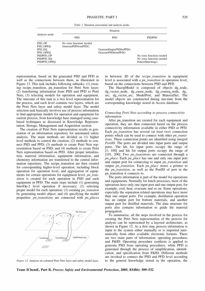
representation, based on the generated PSD and PFD aswell as the connections between them, as illustrated inFigure 13. This task includes following subtasks: (1) creat-ing recipe_transition, pn_transition for Petri Nets layer;(2) transferring information from PSD and PFD to PetriNets; (3) selecting models for operation and equipment.The outcome of this task is a two level representation forthe process, and each level contains two layers, which arethe Petri Nets layer and safety model layer. The modelselection task basically involves use of process informationto find appropriate models for operation and equipment forcurrent process, from knowledge base managed using case-based techniques as discussed in Knowledge Represen-tation, Storage, Management and Acquisition section.The creation of Petri Nets representation results in gen-
eration of an information repository for automated safetyanalysis. The main methods are divided as (1) higherlevel methods to control the creation; (2) methods to con-nect PSD and PFD; (3) methods to create Petri Nets rep-resentation based on PSD; and (4) methods to create PetriNets representation based on PFD. After proper initializa-tion, material information, equipment information, andchemistry information are transferred to the central infor-mation repository. The recipe_transition are then createdfor corresponding higher-level operation, including blockoperation for operation level, and aggregation of equip-ments for certain operations for equipment level. pn_tran-sition is created for each operation in PSD and eachequipment in PFD. The main steps include (1) generatingInterOp-2 level operation if necessary; (2) selectingproper model for each operation; (3) creating pn_transitonby generating model object; and (4) specifying the modelproperties. pn_transitions are connected with pn_places
in between. ID of the recipe_transition in equipmentlevel is associated with a pn_transition in operation level,based on the connections between PSD and PFD.
The HazopModel is composed of objects dg_node,dg_vector_node, dg_cause_node, dg_conseq_node, dg_arc, dg_vector_arc, ModelPort, and MaterialSet. Themodel objects are constructed during run-time from thecorresponding knowledge stored in Access database.
Connecting Petri Nets according to process connectivityinformation
After pn_transition are created for each equipment andoperation, they are then connected based on the processconnectivity information available in either PSD or PFD.Each pn_transition has several (at least two) connectionpoints which can be used to connect with other pn_transi-tions. These connection points are identified using integralPortID. The ports are divided into input ports and outputports. The Ids for input ports occupy the range of[1, 100] and Ids for output ports occupy the range of[101, 200]. Two pn_transitions are connected through apn_place. Each pn_place has one and only one input portand output port for connecting to input pn_transition andoutput pn_transition. Each pn_place stores a pointer tothe pn_transition, as well as the PortID of port in thepn_transition it connects to.
The ports information is part of the model for operationsand equipments. Normally for batch processes, most of theoperations have only one input port and one output port, forexample, cool, heat, evacuate and so on. Some operations,especially the separation related operations may have morethan one output ports. For example, distillation operationhas an output port for bottom materials, and anotheroutput port for distilled materials. The data structure forports also contains information to guide the materialpropagation.
To summarize, all the steps involved in the process forcreating the Petri Nets representation of the process foranalysis can be represented by a layered architecture, asshown in Figure 12. As a first step, process information isinput to the system either manually or is imported auto-matically from other available electronic formats. Thereare two main parts of information: operating proceduresand P&ID. Operating procedure synthesis is applied togenerate PSD from operating procedures, while PFD isgenerated through the process of simplification, identifi-cation, and specification from P&ID. Different methodsare invoked to connect the PSD and PFD level accordingto the general knowledge stored in the operation, the
Table 1. Situation assessment and analysis mode.
Analysis mode
Situation
PSD PFD PSDPFD
PSD_OP No extra functions neededPSD_OPEQ GeneratePDFfromPSD()PFD_EQ GenerateEmptyPSDforPFD()PFD_OPEQ GeneratePSDfromPFD()PSDPFD_OP No extra functions neededPSDPFD_EQ No extra functions neededPSDPFD_OPEQ PatternMatching()
Figure 13. Analysis on coloured Petri Nets layer and safety model layer.
Trans IChemE, Part B, Process Safety and Environmental Protection, 2005, 83(B6): 509–532
PHASUITE: PART I 529

availability of process information and the user specifica-tion. Then the Petri Nets representations are created fromPSD and PFD, and are connected based on the relationbetween PSD and PFD. Beneath the Petri Nets represen-tation, safety models are selected for each operation andequipment from the knowledge base. Models are con-structed from the model storage in Access database, andinitialized according to the process information.
Two-Level, Two Layer Reasoning Engine
The procedures for creating Petri Nets representationcreate two representation levels for the process, namelyoperation level and equipment level. Each Petri Nets rep-resentation level is further divided into Petri Nets layerand safety model layer. The functionalities required foranalysis on the two layers are same regardless of the analy-sis that would be performed on the operation level or onequipment level.
Two-layer reasoning engineThe two-layer reasoning engine is a very important com-
ponent of the system. The two layers are Petri Nets layerand safety model layer. All the connection information ispresent in Petri Nets layer and there is no connectionbetween the safety models in the model layer, as shownin Figure 13. The analysis task contains two main subtasks:material propagation and deviation propagation. The intentof material propagation is to specify the materials for eachoperation and equipment. The material propagation is onlycarried out in Petri Nets layer. The outcomes of materialpropagation, which are the materials in specified materialsets of each operation, are saved within pn_place. Themain methods related to material propagation include(1) method to control the propagation of the materials;(2) method to deal with chemistry related operations, i.e.,operation or equipment involved with different kinds ofseparations and reactions; and (3) method to calculateand determine the range of the operating conditions, i.e.,pressure, temperature, level, and so on. Material propa-gation starts from pn_transition which do not have parentpn_transition, and propagates downstream following theconnection established in the Petri Nets layer. The propa-gation stops only when the current path hits a dead end.For deviation propagation, the Petri Nets layer is used to
control the propagation between operations or equipments.The model layer is used to generate HAZOP analysisresults given the process operating conditions and materialsinvolved. The basic steps for analysis of a specific devi-ation include:
(1) Initialization and preparation for analysis.(2) Local propagation to find consequences for the devi-
ation inside the same pn_transition (shown as step 1in Figure 13).
(3) Generation of current process conditions, and transfer-ing the control to Petri Nets layer (shown as step 2 inFigure 13).
(4) If a pn_transition downstream still exists in Petri Netslayer, following the connection to propagate the devia-tion to next pn_transition (shown as step 3 inFigure 13).
(5) Repetition from step 2, until reaching the last pn_transition in Petri Nets layer.
(6) Similar steps are taken for cause analysis, with onlychange being that the direction of the propagation isupstream rather than downstream.
The methods for Petri Nets layer propagation are storedwithin the class HighSimEng, and the methods for safetymodel layer propagation are stored within the class Low-SimEng. Analysis on single deviation starts from a call toHighSimEng. After verifying that the deviation is valid bya call to the HAZOPModel embedded in the pn_transition,HighSimEng is then invoked with the information on theexact location of the deviation in the digraph represen-tation of the relations between process variables. Thetasks for initialization and housekeeping, such as cleaningthe status variables, recording deviation location, and soon, are carried out by HighSimEng. There are twomethods of LowSimEng which can be called in HighSimEng to invoke the LowSimEng for reasoning on safetymodel layer. One is used when the exact location of thedeviation in the digraph is known, that is, when the devi-ation is the starting point of the analysis. The other is usedwhen there is no specified starting point, i.e., the deviationis propagated down/up from upstream/downstreampn_transitions. In fact, the latter one calls the previousmethod with all the possible starting points in a pn_transi-tion. The iteration is controlled by HighSimEng. After thelocal propagation in the model layer, the process con-ditions which may change due to introduction of the devi-ation are generated. The process conditions are stored in apn_token with parameters for status of the mass, heat,flow rate, pressure and the concentration for each individ-ual material involved in the operation. Status of processvariables for the downstream/upstream pn_transition arespecified according to the information stored in thetoken, and then a call to LowSimEng transfers the controlto LowSimEng.
There is no connection in the model layer, and the Low-SimEng works only on a single safety model. Depth firstsearch methods are used for the local propagation. Follow-ing the connections on dg_node as represented by the arcs,the node states of the next node or previous node are deter-mined. The local propagation continuous until the nextnode is a consequence node, or a cause node. Then the con-sequences or the causes for the deviation are assessed. Therules for assessment are evaluated by current pn_transition.As discussed in Knowledge Representation, Storage, Man-agement and Acquisition section, the conditions, includingparameter conditions, material conditions, equipment con-ditions and process conditions are parsed by a parser todetermine the symbols and the relations between the sym-bols. The symbols correspond to basic process propertiesincluding material properties, material sets, parameters,and process conditions. Combination of material propertiescan also be used, and the criteria of assessing the combinedcondition are also part of the knowledge base. If all the con-ditions are satisfied, the consequences or causes are gener-ated by specifying the material and equipment involved. Incurrent implementation, in the text strings for consequenceand cause, some identifiers have been used to determinewhat process specific information is to be inserted in. Forexample, in the cause of high pressure in Empty operation,
Trans IChemE, Part B, Process Safety and Environmental Protection, 2005, 83(B6): 509–532
530 ZHAO et al.

‘thermal expansion of cryogenic materials (kmateriall)’,‘kmateriall’ is an identifier. When generating the cause,the identifier ‘kmateriall’ is replaced by a string containingnames of the materials satisfying the material conditions.Other identifiers include kequipmentl for specifying mainequipment of the operation, ktoequipmentl and kfromequip-mentl for specifying information about special equipments.Other identifiers can also be added and the correspondingprocess information can be defined in knowledge base. Atypical result contains information of the location of thedeviation specified by the ID of the operation and unit oper-ation, the deviation type, cause, consequence, the locationof the cause, and the location of the consequence, the safe-guard, severity and recommendation. Some specificationsfor the result are generated from information recordedduring analysis, while some information is generatedfrom the rules for assessment of the consequence and thecause. Each result also contains a causal path to recordevery node the analysis path goes through from startingdeviation to the end deviation. The result is then stored incurrent pn_transition.
Reasoning on two levelsAs shown in previous sections, the process could be
abstracted into two levels, operation level and equipmentlevel. Both the levels are represented using Petri Netswith a model layer beneath each of them. The two-layerreasoning engine is used to carry out the analysis onthese two levels, as illustrated in Figure 14. The reasoningon operation level is first carried out, and the analysis onequipment level is controlled by operation level. In thePetri Nets representation layer, the connection betweenthese two levels is through ID of the equipment recipe_transition embedded in the operation pn_transition. In themodel layer, the connection is through the mutual processvariables. During the method call to HighSimEng, afterthe local deviation propagation in operation level, analysisis carried out in equipment level.
CONCLUSIONS
As a long-term vision, for PHASuite to become a suc-cessful process safety analysis tool, it should possess sev-eral properties. First and most important of all, it shouldhave an open structure, within which users are able toadd knowledge to the system with little help from knowl-edge engineers. The open structure also makes it possibleto create standards for causal model. Information sharing
with other tools is also important to reduce the effort ofreentering process information and to improve the useof the safety analysis results. The system is an informationconsumer since it shares process information with othersoftware packages, and also an information producersince it generates safety analysis results and shares theresults with other software packages including abnormalsituation management tools, operator training tools andso on. The tool could also be used as a company-widerepository for knowledge on operating procedures andsafety.
This vision is important not only for the progress of thistool, but it also serves as a guideline for designing andimplementing the current version. Based on this vision, aknowledge engineering framework for automated HAZOPanalysis for chemical processes has been proposed. The fra-mework acts as the guide for the development of currentversion of PHASuite and also lays out a good foundationfor future development. The main components of the fra-mework include: (1) ontologies based information sharing;(2) model-based knowledge representation for operationknowledge as well as safety knowledge; (3) relational data-base based knowledge storage; and (4) case-based tech-nique for knowledge management and for incorporatingexperience into the system. Powerful reasoning method-ologies based on various artificial intelligence techniqueshave also been developed. Coloured Petri Nets represen-tation is created based on process specific information. Aprocess is abstracted to two levels, operation level andequipment level. These two levels are bridged using func-tional representation. Analysis is carried out on both thelevels.
PHASuite, a sophisticated software system for auto-mated process safety analysis using HAZOP technique,has been constructed based on the above framework.Software engineering methodologies are applied toensure the quality, flexibility, and easy maintenance ofthe system. Component programming strategies are usedto construct the two-level and two-layer reasoningengine that performs reasoning on the Coloured PetriNets representation using the knowledge base to generateHAZOP results. Auxiliary system components, includinggraphical user interface, results management, and objectlayers to process information and knowledge base, havebeen built to make the system ready-to-use. The workdone here is ready for real-life applications (some partsof the work have already been extensively tested), andits open structure ensures scope for further improvement.A tool for knowledge acquisition is also implemented asan important facility.
The framework has the following characteristics: (1)appropriate representation of HAZOP analysis procedurefor chemical processes; (2) supporting abstraction andanalysis on different level of the process; (3) incorporatinggeneral domain knowledge, as well as experience; (4)learning ability, i.e., the analysis capability and qualityshould increase as more processes are analysed; and (5)easy to understand and implement. From applicationpoint of view, this system can: (1) improve quality ofHAZOP analysis; (2) save time and effort of human expertsinvolved in performing HAZOP analysis; (3) easily incor-porate further enhancement; and (4) integrate with otherrelated software systems.
Figure 14. Analysis on operation level and equipment level.
Trans IChemE, Part B, Process Safety and Environmental Protection, 2005, 83(B6): 509–532
PHASUITE: PART I 531
REFERENCES
Aamodt, A. and Plaza E., 1994, Case-based reasoning: foundational issues,methodological variations, and system approaches, AI Communications,7(1): 39–59.
Abernethy, N.F. and Altman, R.B., 1989, SOPHIA: providing basic knowl-edge services with a common DBMS. Proceedings of the 5th KRDBWorkshop, Seattle, WA, USA.
Angele, J., Fensel, D., Landes, D., Neubert, S. and Studer, R., 1993,Model-based and incremental knowledge engineering: the MIKEapproach. Knowledge Oriented Software Design (Elsevier, Amsterdam).
ANSI/ISA-588.01, 1995, Batch Control – part 1: models and terminology.Aspen Technology Inc., 2000, Batch Plus User Manual, Version 2.2.Autodesk Inc., 2002, AutoCAD 2002, http://www.autodesk.com.Bergmann, R., Goker, M., Manago, M. and Wess, S., 1999, DevelopingIndustrial Case-Based Reasoning Applications: the INRECA Method-ology (Springer-Verlag, Berlin Heidelberg, Germany).
Catino, C. and Ungar, L.H., 1995, Model-based approach to automatedhazard identification of chemical plants, AIChE Journal, 41(1): 97–109.
CCPS (Center for Chemical Process Safety), 1985, Guidelines for HazardEvaluation Procedures (American Institute of Chemical Engineers, NewYork, USA).
Chandrasekaran, B., 1994, Functional representation and causal processes,Advances in Computers, 38: 73–143.
Chandrasekaran, B., Josephson, J.R., Davis, J.F. and Rizzoni, G., 1998,Functional and diagrammatic representation for device libraries,Annual Report, Ohio State University, USA.
Davis, R., 1984, Diagnostic reasoning based on structure and behavior,Artificial Intelligence, 24: 347–410.
de Kleer, J. and Brown, J.S., 1984, A qualitative physics based on con-fluences, Artificial Intelligence, 24: 7–83.
Dyadem International Ltd, 2001, PHA-Pro 5 Document.Farquhar, A., Fikes, R., Pratt, W. and Rice, J., 1995, Collaborative ontol-ogy construction for information integration, Technical Report ofKnowledge Systems Laboratory, Stanford University.
Forbus, K.D., 1984, Qualitative process theory, Artificial Intelligence, 24:85–168.
Freeman, R.A. ,Lee, R. and MCYamana, T.P., 1992, Plan HAZOP Studieswith an expert system, Chemical Engineering Progress, 88(8): 28–32.
Gensym, 1997, G2 Reference Manual Version 5.0 (Gensym Corporation,Cambridge, MA, USA).
Goel, A.K. and Stroulia, E., 1996, Functional device models and model-based diagnosis in adaptive design, AI EDAM, 10(4): 355–370.
Gruber, T.R., 1993, Toward principles for the design of ontologies used forknowledge sharing, International Workshop on Formal Ontology,Padova, Italy.
Harold, E.R. and Means, W.S., 2001, XML in a Nutshell, (O’Reilly &Associates, Inc., USA)
Intergraph Corporation, 2002, SmartPlant P&ID, http://www.intergraph.com/ppo/smartplant
Jensen, K., 1996, Colored Petri Nets: Basic Concepts, Analysis Methods,and Practical Use (Springer-Verlag, London, UK).
Kang, B. and Yoon, E.S., 2001, Application of automated hazard analysisby new multiple process-presentation models to chemical plants, Indus-trial Engineering Chemistry Research, 40: 1891–1902.
Karvonen, I., Heino, P. and Suokas, J., 1990, Knowledge-based approachto support HAZOP studies, Technical Research Center of Finland:Research Report.
Kinoshita, A., Umeda, T. and O’Shima, E., 1981, An algorithm forsynthesis of operational sequences of chemical plants, 4th Europeansymposium on computerized control and operation of chemical plants,CHEMCONTROL, Vienna, Austria.
Kletz, T., 1999, Hazop and Hazan: Identifying and Assessing ProcessIndustry Hazards, 4th edition (The Institution of Chemical Engineers,Rugby, UK).
Knowlton, R.E., 1981, An Introduction to Hazard and Operability Studies: TheGuide Word Approach, (Chemetics International Ltd. Vancouver, Canada).
Kolodner, J.L., 1983, Maintaining organization in a dynamic long-termmemory, Cognitive Science, 7: 243–280.
Kolodner, J.L., 1993, Case-Based Reasoning (Morgan Kaufmann Publish-ers, San Mateo, CA, USA).
Nickols, F., 2000, The knowledge in knowledge management, KnowledgeManagement Yearbook (Butterworth-Heinemann, Boston, USA).
Norrie, M.C., Reimer, U., Lippuner, P., Rys, M. and Schek, H.J., 1994,Frames, objects and relations: three semantic levels for knowledgebase systems reasoning, Proceedings of First Workshop of KnowledgeRepresentation Meets Databases, Saarbrucken, Germany.
Pajula, E., Seuranen, T., Koiranen, T. and Hurme, M., 2001, Synthesis ofseparation processes by using case-based reasoning, Computers &Chemical Engineering, 25: 775–782.
Parmar, J.C. and Lees, F.P., 1987, The propagation of faults in processplants, Reliability Engineering, 17: 277–302.
Pegah, M., Sticklen, J. and Bond, W., 1993, Functional representation andreasoning about the F/A-18 aircraft fuel system, IEEE Expert, 8(2):65–71.
Peterson, J., 1981, Petri Net Theory and the Modeling of Systems(Prentice-Hall Inc., NJ, USA).
Poeck, K. and Gappa, U., 1993, Making role-limiting shells more flexible,Proceedings of the 7th European Knowledge Acquisition Workshop,Toulouse and Caylus, France.
Ramakrishnan, R. and Gehrke, J., 1999, Database Management Systems,2nd edition (McGraw Hill, USA).
Ramanathan, R., 1994, Providing object-oriented access to a relationaldatabase, In Cordes, D. and Vrbsky, S. (eds), Proceedings of the 32ndAnnual Southeast Conference, Tuscaloosa, Alabama, USA.
Riesbeck, C.K. and Schank, R.C., 1989, Inside Case-Based Reasoning(Lawrence Erlbaum Associates Publishers, NJ, USA).
Rich, E. and Knight, K., 1990, Artificial Intelligence, 2nd edition(McGraw-Hill, NY, USA).
Rich, S.H. and Venkatasubramanian, V., 1987, Model-based reasoning indiagnostic expert systems for chemical process plants, Computers &Chemical Engineering, 11(2): 111–122.
Schank, R., 1982, Dynamic Memory: A Theory of Reminding and Learningin Computers and People (Cambridge University Press, NY, USA).
Sembugamoorthy, V. and Chandrasekaran, B., 1986, Functional represen-tation of devices and compilation of diagnostic problem-solving sys-tems, In Experience, Memory, and Reasoning (Lawrence ErlbaumAssociates, NJ, USA).
Slade, S., 1991, Case-based reasoning—a research paradigm, AI Maga-zine, 12(1): 42–55.
Srinivasan, R. and Venkatasubramanian, V., 1998, Automating HAZOPanalysis of batch chemical plants: Part I. The knowledge representationframework, Computers & Chemical Engineering, 22(9): 1345–1355.
Sticklen, J., Kamel, A. and Bond, W.E., 1991, Integrating quantitative andqualitative computations in a functional framework, EngineeringApplications of Artificial Intelligence, 4(1): 1–10.
Uschold, M. and Gruninger, M., 1996, Ontologies, principles, methods andapplications, The Knowledge Engineering Review, 11(2): 93–136.
Vaidhyanathan, R., 1995, A Model-Based Framework for AutomatingHAZOP Analysis of Continuous Process Plants, PhD thesis, LIPSLab, Purdue University.
Vaidhyanathan, R. and Venkatasubramanian, V., 1996, HAZOPExpert: anexpert system for automating HAZOP analysis, Process Safety Pro-gress, 15(2): 80–88.
Venkatasubramanian, V. and Rich, S.H., 1988, An object-oriented two-tierarchitecture for integrating compiled and deep-level knowledge forprocess diagnosis, Computer & Chemical Engineering, 12(9–10):903–921.
Venkatasubramanian, V., Zhao, J. and and Viswanathan, S., 2000, Intelli-gent systems for HAZOP analysis of complex process plants, Computers& Chemical Engineering, 24: 2291–2302.
Viswanathan, S., 2000, A hierarchical model-based intelligent systemsframework for synthesis of safe batch operating procedures, PhDThesis, Purdue University, USA.
Viswanathan, S., Mockus, L. and Venkatasubramanian, V., 1998, iTOPS:an intelligent tool for operating procedures synthesis, Computers &Chemical Engineering, 22: S601–S608.
Walas, S., 1988, Chemical Process Equipment: Selection and Design(Butterworth-Heinemann, MA, USA).
Waters, A. and Ponton, J.W., 1989, Qualitative simulation and fault propa-gation in process plants, Trans IChemE, Chemical EngineeringResearch and Design, 67(4): 407–422.
Weiss, S., Kulikowski, C., Amarel, S. and Safer, A., 1978, A model-basedmethod for computer-aided medical decision making, Artificial Intelli-gence, 11: 145–172.
Xia, Q. and Rao, M., 1999, Dynamic case-based reasoning for processoperation support systems, Engineering Applications of Artificial Intel-ligence, 12: 343–361.
Zhao, J., Viswanathan, S., Zhao, C., Mu, F. and Venkatasubramanian, V.,2000, Computer-integrated tools for batch process development, Com-puters & Chemical Engineering, 24: 1529–1533.
The manuscript was received 1 March 2004 and accepted for publi-cation after revision 4 April 2005.
Trans IChemE, Part B, Process Safety and Environmental Protection, 2005, 83(B6): 509–532
532 ZHAO et al.