phenom 100 manual 1.0
TRANSCRIPT
feelThere LE: Phenom 100 by Embraer
Addon Aircraft for Microsoft's Flight Simulator 2004: A Century of Flight and Flight Simulator X
OPERATIONS MANUAL
feelThere LE: Phenom 100 by Embraer Page 1
Table of ContentsWHAT THIS MANUAL IS AND ISN'T.....................................................................................................................................3READ ME FIRST.......................................................................................................................................................................3The Simulated Phenom 100:.......................................................................................................................................................8Introduction Flight.......................................................................................................................................................................9Main Panel.................................................................................................................................................................................18
Integrated Standby Instrument System (ISIS).....................................................................................................................18Audio sub-panel...................................................................................................................................................................18Autopilot Sub-panel.............................................................................................................................................................19Primary Flight Display........................................................................................................................................................20Multi-Function Display.......................................................................................................................................................24Lights Panel.........................................................................................................................................................................26Pressurization and Air Conditioning Systems Panel...........................................................................................................27Fuel, Hydraulic Systems and FMS keypad Panel................................................................................................................27Electrical, Fire Extinguisher and Engine Start/Stop Panel..................................................................................................29Center Pedestal....................................................................................................................................................................30
Full Authority Digital Electronic Control.................................................................................................................................31Reference and Performance Speeds..........................................................................................................................................32Structural Airspeeds..................................................................................................................................................................33Normal Checklists.....................................................................................................................................................................34EICAS Messages.......................................................................................................................................................................37Abbreviations............................................................................................................................................................................42CREDITS, RESOURCES AND COPYRIGHTS......................................................................................................................43
feelThere LE: Phenom 100 by Embraer Page 2
WHAT THIS MANUAL IS AND ISN'T:This manual is intended to provided the average flight simulation enthusiast with the information necessary to fly the Embraer Phenom 100. This includes: basic use of the simulated FMC, system prep, taxi, takeoff, flight, descent, approach, landing, taxi and shutdown. This manual is not intended to provide 'all there is to know' about the Phenom. Real world manuals are thousands of pages long and require pilots to attend months of education (not including the flight hours pilots must collect in single and twin engine piston-prop planes prior to being approved for jet powered aircraft training).
There are multiple Internet sources for detailed information on flying the Phenom. feelThere encourages you to use your favorite search engine to find details about the aircraft not covered in these pages. The feelThere support forums are also available for Phenom pilots (real and simulated) to discuss systems and procedures.
READ ME FIRSTThroughout the manual the terms FS, flightsim, and flight simulator are used when referring to Microsoft Flight Simulator. Only in cases where Phenom function(s) is different in Flight Simulator 2004 'a century of flight' (FS9) or FSX (FS10) will the specific version of the simulator be noted.
You must have a fully updated version of FS that includes all service patches released by Microsoft. At the time of the Phenom's release this is FS9 Service Patch 1 (FS9.1) and FSX SP1 (FSXsp1) and SP2 (FSXsp2). FSX users may also have installed Acceleration (FSA) or the FS Gold (FSG) versions of the simulator. FSA and FSG include service packs one and two.
The absolute minimum computer specifications required to run the Phenom are: Pentium IV 1,4 GHz, 256MB RAM, 128MB Graphics, FS2004 or FSX, Windows 2000, XP, Vista and Windows 7. Each computer system reacts differently to all software, so the settings required to gain optimum performance must be selected by the user. Review the Configuration Utility information outlined below on adjusting the Phenom's gauges to optimize in-game function.
The Phenom is compatible with the GoFlight AP modules, Track IR and Squawkbox 3.
Run the self extracting installer for the version of flight simulator version on your system to install the Phenom. Be sure to run the correct installer as the FS9 version will not work in FSX, nor the FSX run in FS9. After starting the installer enter the keycode provided for your product. The installer will choose a file path matching a default FS setup. If you have a non-standard file structure for FS you must direct the installer to the correct root FS folder. If you use the VISTA or win7 operating systems be sure UAC is OFF installation and you run the installer as the 'administrator'. Do not run the installer in winXP compatibility mode. FeelThere recommends that you do not install FS into the default '/programs' directory if you use the win7 operating system.
feelThere LE: Phenom 100 by Embraer Page 3
The first time selecting the Phenom in FSX you must approve all gauges and modules for the aircraft to run correctly.
Our Phenom was built using many custom non standard commands and gauges; so it is imperative you read this documentation before your flight.
Computer MouseThe Phenom is designed to work with a computer mouse set to the following button and wheel configuration:
• left mouse button• center scroll wheel that can also be used as a center mouse button• right mouse button.
Some highly customized pointing devices require adjustment in order to comply with the above interface architecture.
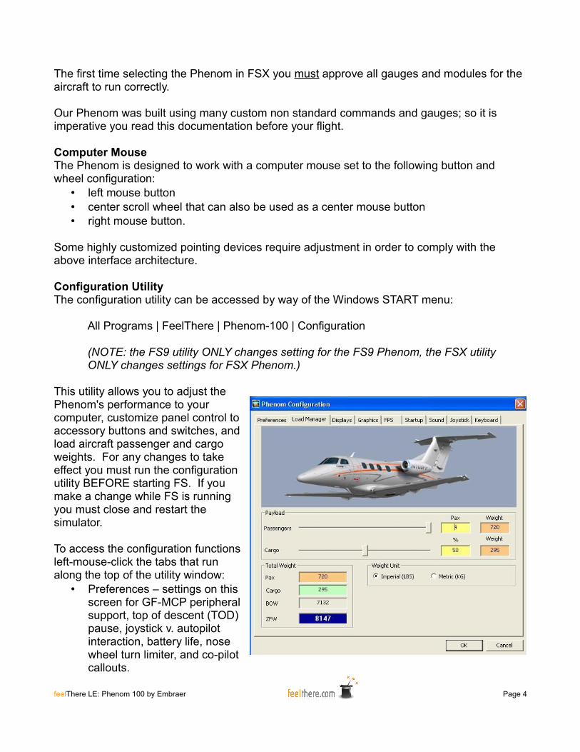
Configuration UtilityThe configuration utility can be accessed by way of the Windows START menu:
All Programs | FeelThere | Phenom-100 | Configuration
(NOTE: the FS9 utility ONLY changes setting for the FS9 Phenom, the FSX utility ONLY changes settings for FSX Phenom.)
This utility allows you to adjust the Phenom's performance to your computer, customize panel control to accessory buttons and switches, and load aircraft passenger and cargo weights. For any changes to take effect you must run the configuration utility BEFORE starting FS. If you make a change while FS is running you must close and restart the simulator.
To access the configuration functions left-mouse-click the tabs that run along the top of the utility window:
• Preferences – settings on this screen for GF-MCP peripheral support, top of descent (TOD) pause, joystick v. autopilot interaction, battery life, nose wheel turn limiter, and co-pilot callouts.
feelThere LE: Phenom 100 by Embraer Page 4
• Load Manager – set passenger and cargo weights. The units clickboxes change the measurement system used on the load manager screen, not in FS. Once you have set passenger and cargo loads you must click the OK button for the Phenom's cfg file to be updated. Changes made here are only seen in-game after restating FS.
• Displays – set the Phenom's default atmospheric pressure system: HPA (hPa) or IN (inHg). Here you can also set the default weight system: pound or kilogram.
• Graphics – set how the main panel graphics are rendered by your computer. Each computer is different, and the user must try different settings to maximize performance.
• FPS - adjusting the sliders on this page increases/decrease the indicated gauge refresh rate. Decreasing refresh rates will result in higher scenery performance within FS. Each computer system is different, so you will need to try different settings to maximize game performance.
• Startup – set the condition of the aircraft when loading into FS: cold & dark, ready to start, engines running and standard or widescreen panel.
• Sound – sets the master volume for the panel's custom gauges.• Joystick – set the joystick, or yoke, buttons to control Touch Control Steering (TCS),
autopilot quick disconnect and TO/GA.• Keyboard – set keyboard shortcuts for panel functions using this screen.
NOTE: any changes made will not take effect until the OK button is clicked. Changes made will only been seen within flight simulator after restarting the game.
feelThere LE Level of SimulationSometimes you just want to fly, or you are new to flight simulation, and don't wish spend 30 minutes preflighting an aircraft. Maybe today you don't want to spend much effort to create a flightplan and programming a flight management computer. feelThere LE aircraft are designed to be detailed enough to immerse you in the simulation experience and quickly get into the air from power-up to takeoff. Many systems are modeled, just not every system. You will find the level of detailed is greater than any flight simulator default aircraft. The systems that are modeled behave correctly; or are only slightly simplified. LE aircraft are designed for fun … which is the point for playing Microsoft's Flight Simulator.
Sub-Panel Windows
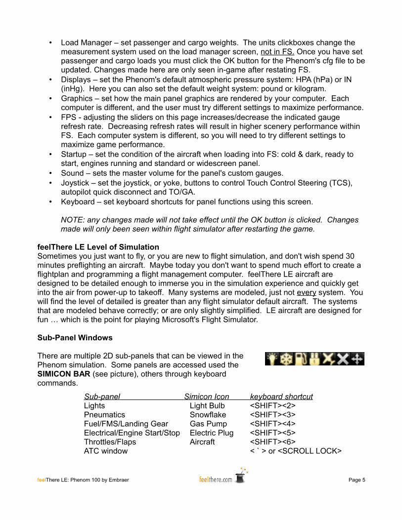
There are multiple 2D sub-panels that can be viewed in the Phenom simulation. Some panels are accessed used the SIMICON BAR (see picture), others through keyboard commands.
Sub-panel Simicon Icon keyboard shortcut Lights Light Bulb <SHIFT><2>Pneumatics Snowflake <SHIFT><3>Fuel/FMS/Landing Gear Gas Pump <SHIFT><4>Electrical/Engine Start/Stop Electric Plug <SHIFT><5>Throttles/Flaps Aircraft <SHIFT><6>ATC window < ` > or <SCROLL LOCK>
feelThere LE: Phenom 100 by Embraer Page 5
To close the Simicon Bar click the 'X'. The Simicon Bar can be reopened with <SHIFT><7> keyboard shortcut. To move the Simicon Bar to another location on the computer monitor click and hold on the arrowed cross.
Panel KnobsThe autopilot knobs are adjusted in the following ways:
• with the pointer over the knob the mouse wheel can be used to increase/decrease the set value
• left of knob center left-mouse-click will increase value by one• left of knob center right-mouse-click will increase value by ten• right of center left click will decrease value by one• right of center right click will decrease value by ten• many knobs will react to a center mouse button click by synchronizing a setting to the
aircraft's current orientation, toggling displays, or engaging an function.
The knobs on the main panel displays bezel are adjusted in the following ways:• with the pointer over the knob the mouse wheel can be used to increase/decrease the
set value. The pointer above the center of the knob increases the value, the lower half of the knob the value is decreased.
• left of knob and above center left-mouse-click will increase the value by ten.• left of knob and below center left-mouse-click will increase the value by one.• right of and above center left click will decrease the value by ten.• right of and below center left click will decrease the value by one.• a center mouse button click will 'push' the button.
In addition to the knob control functions explained above, many of the Phenom's knobs have an inner and outer ring. For these knobs a click on upper half will rotate outer knob, and click on lower half will rotate inner knob.
Many of the knobs are turned, not 'clicked', when in the VC cockpit. When unable to click a knob use a left-mouse-click and hold the knob; then 'turn' by moving the mouse is a looping motion.
Safety covered buttons and knobsMany of the Phenom buttons and knobs have a safety cover and therefore inaccessible. In order to access these controls you must right-mouse-click to open the cover. Once the cover has been opened you can use the shielded knob or button.
SoftkeysThe Phenom panel uses the softkeys located on the the bottom of the display screens to access many of the autopilot an aircraft systems. When softkey use is required this manual will outline the pathway steps by the following notation -
<softkey name> | <sub-softkey name> | <sub-sub-softkey name> | etc.
feelThere LE: Phenom 100 by Embraer Page 6
FMS KnobMany of the panel values are set using the FMS knob located at the lower-right bezel of each panel screen. In general after selecting a function using a softkey the cursor is activated by clicking the center of FMS knob. The active item will be highlighted cyan (light blue) and is then adjusted by turning the knob (left-mouse-click or center-mouse-wheel scrolling).
The FMS knob is made of an inner and out ring. Each ring can be turned. The values adjusted by turning each ring differ depending on what screen or function is active.
Navigation ModesThe system sending navigation information to the autopilot is selected by pressing the CDI softkey on the PFD. The first click will activate (cyan boarder will appear) the NAV1 standby frequency. Pressing the CDI softkey will cycle through the available navigation source modes.
GPS – the autopilot will follow the loaded flight simulator flightplan as shown on the MFD's map.
LOC – the autopilot will follow the follow the localizer and glideslope when an ILS freqency the is entered into the NAV radio.
VOR – when an active frequency is set in the NAV radio the autopilot will follow the VOR radial set with the CRS knob.
Cruise Speed ControlOnly when the aircraft is in altitude hold mode (ALT displayed on the PFD annunciator panel) with the autopilot ON can the Cruse Speed Control (CSC) be used. Pressing the CSC button on the guidance panel the autopilot will control thrust to maintain the cruise speed selected with the SPD knob.
Flight Plan EntryThe simulation does not allow for flighplan entry using the FMS keyboard. You must create and edit routes using the Microsoft Flight Simulator route finder, save the plan, and then load the plan into the FMC.
The waypoint and airport database included with Flight Simulator is used to identify flightplan waypoints. For this reason only flightplans created using the FS Flightplanner are fully supported.
Direct ToYou can command the FMS to fly direct to a waypoint using the Direct To function.
feelThere LE: Phenom 100 by Embraer Page 7
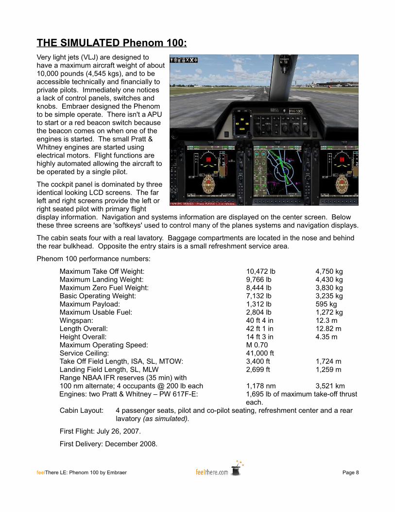
THE SIMULATED Phenom 100 : Very light jets (VLJ) are designed to have a maximum aircraft weight of about 10,000 pounds (4,545 kgs), and to be accessible technically and financially to private pilots. Immediately one notices a lack of control panels, switches and knobs. Embraer designed the Phenom to be simple operate. There isn't a APU to start or a red beacon switch because the beacon comes on when one of the engines is started. The small Pratt & Whitney engines are started using electrical motors. Flight functions are highly automated allowing the aircraft to be operated by a single pilot.
The cockpit panel is dominated by three identical looking LCD screens. The far left and right screens provide the left or right seated pilot with primary flight display information. Navigation and systems information are displayed on the center screen. Below these three screens are 'softkeys' used to control many of the planes systems and navigation displays.
The cabin seats four with a real lavatory. Baggage compartments are located in the nose and behind the rear bulkhead. Opposite the entry stairs is a small refreshment service area.
Phenom 100 performance numbers:
Maximum Take Off Weight: 10,472 lb 4,750 kgMaximum Landing Weight: 9,766 lb 4,430 kgMaximum Zero Fuel Weight: 8,444 lb 3,830 kgBasic Operating Weight: 7,132 lb 3,235 kgMaximum Payload: 1,312 lb 595 kgMaximum Usable Fuel: 2,804 lb 1,272 kgWingspan: 40 ft 4 in 12.3 mLength Overall: 42 ft 1 in 12.82 mHeight Overall: 14 ft 3 in 4.35 mMaximum Operating Speed: M 0.70Service Ceiling: 41,000 ftTake Off Field Length, ISA, SL, MTOW: 3,400 ft 1,724 mLanding Field Length, SL, MLW 2,699 ft 1,259 mRange NBAA IFR reserves (35 min) with 100 nm alternate; 4 occupants @ 200 lb each 1,178 nm 3,521 kmEngines: two Pratt & Whitney – PW 617F-E: 1,695 lb of maximum take-off thrust
each.Cabin Layout: 4 passenger seats, pilot and co-pilot seating, refreshment center and a rear
lavatory (as simulated).
First Flight: July 26, 2007.
First Delivery: December 2008.
feelThere LE: Phenom 100 by Embraer Page 8
Introduction Flight
To familiarize you with the Phenom 100 you will be taking a introduction flight from Scotsdale Airport (KSDL), Arizona (USA) to Las Vegas McCarran International (KLAS), Nevada (USA). This is a real-world Phenom 100 flight following this flightplan -
KSDL JONHH1 IGM KADDY1 KLAS
Cruise altitude for this short flight will be FL320 (32,000 ft). Flight time is expected to be fifty-five minutes.
JONHH1 is the standard instrument departure (SID), and KADDY1 is the Standard Terminal Arrival (STAR). Charts for the flight are located in the 'FS root folder' / FeelThere / Phenom / intro_flight_charts. It is recommended that you print the charts used in this introduction to use as reference during the flight. The airport charts included with this software are out-of-date and not to be used for real-world aviation.
This introduction will take about 90 minutes to complete. The terminal and runway instructions are based on default FS9 and FSX scenery. During this flight do not use FS's ATC as all 'traffic control' will be outlined in the text.
The Phenom 100 Normal Checklist are used during this introduction. It is recommended that you print the checklists beginning on page 34 of this manual to use as reference during the flight.
Using the Phenom Configuration Utility make the following settings -• On the 'Preferences' tab select disable joystick axis when autopilot is on and play
callouts.• On the 'Weight' tab set the Phenom to display weights in pounds.• On the 'Pressure' tab set the Phenom to display pressure as IN (inHg).• You have a full flight of volunteers … I mean passengers today. Under the 'Load
Manger' tap set the Phenom passenger number to 4, and the cargo to 50%. The aircraft Zero Fuel Weight (ZFW) will be 8,147 lbs. Write this number down as you will need it for setting the appropriate v-speeds for takeoff and landing.
• On the 'Joystick' tab set the Autopilot disconnect button for your controller by clicking the 'select' button and pressing the controller button.
• On the 'Startup' tab select cold and dark as the aircraft condition when loaded into FS.
Save the above settings by pressing the OK button.
feelThere LE: Phenom 100 by Embraer Page 9

Start FS and create a new flight with these settings -• Select the default Cessna as the aircraft.• Set 50% fuel loaded in each of the plane's tanks.• Select the departure location as KSDL. Choose any medium GA parking location.• Set the weather theme to clear and calm.• Set the time to 12:00 PM local.• Set AI traffic to zero.
Now start the game.
Once FS has loaded turn OFF the Cessna's engine, and confirm the BATT and AVIONICS masters are ON. Wait 15 or so seconds and use FS's pull-down 'Select Aircraft' menu to select the feelThere Phenom. You may choose any of the available liveries (paints).
Once the Phenom has loaded. Open the Electrical sub-panel by clicking power plug icon on simicon panel or <SHIFT><*>. Turn ON the aircraft's batteries to power the aircraft. During power up the caution alarm can be silenced by pressing the PFD's far right softkey. At this time you can also open the cabin door so your passengers can board the aircraft.
The PFD's and MFD screens will activate and the FMC will use the GPS to set the aircraft's location. Until the aircraft's location has been initialized (takes about two minutes) the PFDs will show only limited information and fault indications. While the FMC initializes follow the COCKPIT/CABIN SAFETY CHECK checklist.
Once the first checklist is completed you can load the flightplan into the FMC. Flightplans and most autopilot settings can be programmed prior to the FMC completing position initialization. Using the FS pull-down menu open the FS flightplanner. Select the flightplan named 'KSDL-KLAS'. If prompted DO NOT let FS reposition the aircraft. The flightplan is now loaded into the FMC. To see the flightplan on the MFD press the FPL bezel button.
The flightplan waypoints are:
KSDL (departure airport) JONHH ZEPER KARLO CHILY RAMSY SISIE IGM COTES ZIVSI KADDY KLAS (arrival airport)
Currently the batteries are being used to power the aircraft. Thirty seconds after the plane's parking brakes are set the ground crew will have set up and connect the Ground Power Unit (GPU). Open the electrical sub-panel and check that the GPU indicator button is showing 'available'. Press the button and the GPU will be powering the aircraft.
feelThere LE: Phenom 100 by Embraer Page 10
On the PFD press the TMR/REF softkey. This will bring up the TIMER/SPEEDS window on the PFD. Using the FMC wheel you will now set the takeoff v-speeds for a Flaps 1 takoff based on the aircraft's weight:
• V1 = 92• Vr = 92• V2 = 99• Vfs = 122
The above v-speeds come from the Flaps 1 speed table on page 32 of the manual. Earlier you noted the Zero Fuel Weight of the plane. When loading the Cessna 172 you set the fuel percentage as 50%. Looking on the Phenom's MFD notice that the fuel weight is listed as 1400 lbs. Adding the ZFW, 8147, and the weight of the fuel, 1400, gives you an airplane takeoff weight of 9547 lbs. The ZFW plus the fuel is the weight used to select the appropriate takeoff v-speeds.
Place the mouse pointer on lower half of the FMS knob and left-mouse-click or scroll the center mouse wheel to adjust the v-speeds. Place the mouse pointer on lower half of the FMS knob and left-mouse-click or scroll the center mouse wheel to display (ON) or remove (OFF) the v-speed from the PFD speedtape.
These v-speeds will display on the PFD speedtape and the co-pilot will call the speeds during the takeoff roll.
The cruise altitude for this flight will be FL320 (32000 feet). Set this altitude into the autopilot using the ALT select knob. The selected altitude will display above the altitude tape on the PFD.
The local ATIS reports that, “winds calm, pressure 29.92 mb, with aircraft landing and departing from runway 3.”
You will be departing Scotsdale Airport on runway 3. Upon review of the JONHH1 SID departing aircraft turn to 250 degrees after taking off from runway 3. Set the autopilot heading to 250 using the HDG knob. The heading set into the autopilot is indicated on the PFD compass rose.
Set the altimeter to the local pressure of 29.92. Be sure you have also set the ISIS pressure to 29.92.
Now follow the BEFORE ENGINE START checklist, including the IMMEDIATELY PRIOR TO ENGINE START section. The step 'GPU as required' confirm that the GPU indicator button indicates that power is ON. You will skip over the IF NO GPU section as in this situation you have a ground power unit powering the aircraft.
Set the PFD so you have the compass rose pointer indicating the direction to the next GPS waypoint by pressing the BRG1 softkey until the pointer is a magenta color.
feelThere LE: Phenom 100 by Embraer Page 11

Set the NAV2 radio to 115.6. Display the NAV2 indicator on the PFD compass rose by pressing the BRG2 softkey until the pointer is green. You have do thisso you will know when to turn north-west on the 321-degree radial toward the JONHH waypoint.
Confirm that the navigation source is set to GPS. This is indicated at the top of the PFD in the annunciator window as GPS and on the compass rose with an magenta pointer.
You now start the engines. Start the right engine first by turning the START knob to the start position and release. The engine start sequence is fully automatic. The Phenom systems are designed to be automated and reduce pilot workload. Notice that as the right engine starts the red beacon is automatically turned on. Watch the engine status on the system sub-window on the MFD. During power up the caution alarm can be silenced by pressing the PFD's far right softkey.
Once the right engine is running and is stabilized start the left engine.
After the engines are running disconnect the GPU, set takeoff trim to 65 (system sub-panel display goes from amber to green), and flaps to position F1. Note the weight of the fuel indicated on the MFD system display. You will need this number to calculate the landing v-speeds.
Conduct the AFTER ENGINE START checklist.
You are now ready to taxi.
“Phenom 100 taxi to runway 3 via taxiway. Contact tower after holding short runway 3.”
You now have clearance to taxi. Turn on on the taxi lights and release the parking brakes. Advance the throttles to about 45% N1 to get the aircraft moving. Once the aircraft is moving an N1 setting of 35-40% is enough to keep the aircraft moving at a safe speed. Go no faster than 20 knots, and 10 knots when turning.
When you arrive at runway conduct the BEFORE TAKEOFF checklist up to IMMEDIATELY PRIOR TO TAKEOFF. To have the automated system confirm takeoff configuration press the TO CONFIG button on the center pedestal.
You are now ready to taxi onto the runway. “Phenom 100 you are cleared for takeoff. After departure turn to heading 250. You are cleared to climb to your cruise altitude.”
Now complete the IMMEDIATELY PRIOR TO TAKEOFF checklist. Turn on the TCAS system by pressing the XPDR softkey, then MODE softkey, and then the TA/RA softkey.
Once you have lined up on the runway hold the brakes ON and press the TO/GO cheat spot on the glareshield. Advance the throttles so the engines run up and stabilize at 50-55% N1. If all systems are OK release the brakes and push the throttle levers FULL FORWARD.
As the plane accelerates your co-pilot will call out the v-speeds.
feelThere LE: Phenom 100 by Embraer Page 12

At positive rate retract the landing gear. Follow the flight director to maintain the runway heading and initial climb speed of 127kts.
At 500' AGL press the autopilot HDG button. Begin a left hand turn to 250 degrees.
At 1000' AGL press, in order, the AP and the FLC buttons. The autopilot will now control the plane's turn to 250 degrees and control pitch to maintain 127kts. You can now take your hands of your yoke.
At 1500' AGL set the SPD to 160 kts.
As the plane approaches 160 kts retract the flaps.
Set the SPD to 180 kts.
Conduct the AFTER TAKEOFF checklist.
Observe the indications on the PFD's compass rose. When the NAV2 indicator shows you are about the cross the 321-degree radial from the Phoenix VOR turn the HDG knob to 321 degrees. Once the plane turns to 321 degrees make any small adjustments necessary so you are flying directly towards the JONHH waypoint. To assist in your situational awareness you can see the aircraft's location in relation to the flightplan in the MFD.
Once you are flying towards the JOHNN waypoint press the autopilot NAV button. This will arm the FMS to take over flight control once the aircraft intersects the flightplan at JOHNN. The 'armed' status is indicated on the PFD's annunciator window with 'GPS' highlighted in a white box to the left of the green HDG indication.
As the aircraft climbs you can increase the range on the TCAS system from 12 to 20 to 40 nautical miles (nm).
As you cross the JOHNN waypoint the FMS will take over navigation and turn the aircraft towards ZEPER. The FMS will sequence the flightplan waypoints automatically. You can see the current status of the flighplan by pressing the MFD's bezel FPL button.
As you pass through 18000 feet turn off the landing/taxi lights and increase the SPD select knob to 200 kts. As air traffic control is not reporting any turbulence you can no turn off the seatbelt signs and allow the passengers to move about the cabin. Now run thought the CLIMB TRANSITION ALTITUDE checklist.
Watch the indicated airspeed as the aircraft climbs. When the Mach speed indication at the bottom of the speedtape reads 0.55 press (center-mouse-button-click) the SPD select knob. This commands the autopilot to hold the indicated Mach speed, instead of KIAS.
As the aircraft levels off at the cruise altitude of 32000 note that the vertical mode indication goes from ALTS to ALT. When this happens it means the FADEC has recognized that the
feelThere LE: Phenom 100 by Embraer Page 13
cruise altitude has been reached and the engine thrust is now cruise (CRZ) mode. When this happens you can engage the Phenom's 'autothrust' system by pressing the autopilot CSC button. The Phenom's CSC system only works when the aircraft is at the cruise altitude selected using the ALT select knob. Adjust the SPD select knob to M0.61.
As the flight continues monitor the aircraft status on the PFD and MFD.
“Phenom 100 expect landing Las Vegas runway 25 left. Winds are calm. Current pressure is 29.92. Begin descent for published approach at pilot's discretion.”
Looking at the KADDY1 arrival chart you will note that you are to cross waypoint KADDY at 12000 feet at 250 knots. To calculate the top of decent point and rate of descent follow the following instructions -
Descent Calculations
To meet a crossing restriction, or descend to the destination airport, and you have canceled out the FMC's pre-calculation by using the direct-to function, or are off the flightpath use the following equations to determine the top of descent (TOD) location and rate of descent (ROD):
Top of Descent -
To calculate TOD first remove the zeros from the altitude you wish to reach and the plane's current altitude so you have only two digit numbers. Subtract the new altitude from the plane's current altitude. Multiply the result by three and add 10 percent. This gives you the distance from the point you wish to be at your new elevation you need to begin your descent.
Example: you are at FL320 and wish to reach 12000' at waypoint KADDY.
• remove the zeros so you have 32 and 12• subtract 12 from 32 that gives you 20• multiply 20 times three that gives you 60• figure 10 percent of 60 (round up) giving you six• and six to 60 that gives you 66• this means you begin your descent to reach 12000' 66 nm
from KADDY
Rate of Descent -
To calculate ROD half the plane's current airspeed and add a zero to give you the rate of descent.
Example: you are flying at 350 kts ground speed (ground speed is
feelThere LE: Phenom 100 by Embraer Page 14
indicated in the lower left corner of the PFD).
• 350 divided by two equals 175• add a zero means you descent at -1750 ft/min
Due to autopilot limitations round to the next highest 100th. In this case the descent rate will be -1800 ft/min.
Using TOD and ROD together you will arrive at KADDY at the required altitude.
To find when you are 66 nm from KADDY open the flightplan on the MFD. The FMS is indicating the current distance from the next waypoint in the route. The distances between the future waypoints are also listed. Adding up the distances beginning at KADDY and working backwards you have:
• 15 nm between KADDY and ZIVSI• 10 nm between ZIVSI and COTES• 13 nm between COTES and IGM• and a slowly decreasing value between IGM and SISIE.• 15 plus 10 plus 13 equals 38• you know you need to descend 66 nm from KADDY so subtract 38 (the total
distance from KADDY to IGM) from 66. This equals 28.
This calculation means you will begin your descent from FL320 to 12000' 28 nm from IGM.
10 nm from your TOD select the new altitude using the ALT select knob (12000').
As you cross the TOD point 28 nm from IGM press the autopilot VS button and use the VS wheel to select a descent rate of -1800 ft/min.
As you begin the descent the CSC system will disconnect. You now must control the aircraft's throttle setting (thrust) to maintain the required indicated airspeed (KIAS). In general you will want to descent at M0.61 until the indicated airspeed is 250 kts. Keep the aircraft at 250 kts until you are 15 nm from the airport, or slower speed restriction.
Look at the MFD's system display. Note the current value for the fuel on board. Subtract this value from the fuel weight you noted just after your started the engines. You know know how much lighter the aircraft is than when you departed Scotsdale. Subtract the weight of fuel used from the initial aircraft weight when you configured the game for this introduction flight. This is the weight value you now use to calculate the landing v-speeds.
Enter the approach speeds on page 32 based on the aircraft's weight into the PFD.
Now conduct the DESCENT checklist up to TRANSITION LEVEL.
feelThere LE: Phenom 100 by Embraer Page 15

When you pass through 18000' complete the DESCENT checklist.
As you approach the KADDY waypoint use the HDG select knob to set 325 degrees.
When you reach KADDY press the HDG button. The autopilot will turn the plane to 325 degrees.
“Phenom 100 fly straight in Las Vegas runway 25L at intersection PRINO.”
Use the NAV knob on the PFD bezel to set the NAV1 radio backup frequency to 111.75. this is the ILS frequency for runway 25L.
Press the DOUBLE ARROW button above the NAV knob on the PFD bezel to set 111.75 as the active frequency radio freqency.
Press the CDI softkey button so that NAV1 is providing navigation information to the autopilot.
You want to fly towards the PRINO waypoint on the 25L approach. Use the 'direct to' function enter this waypoint into FMC:
• Press the MFD's bezel Direct-to button.• Press (center-mouse-button-click) the MFD's bezel FMC wheel.• Use the FMC alphanumeric keyboard, or computer keyboard, to enter PRINO
into the data field.• Confirm that the FMC has found the correct PRINO waypoint (no more than 20
nm from your current location).• 'Activate' the waypoint by pressing the MFD's bezel Ent button.
On the MFD map you will now see a line that shows the direction to the PRINO waypoint. The heading and distance to PRINO are also indicated along the top of the MFD.
Using the HDG select knob turn the aircraft towards PRINO.
You need to cross PRINO at 8000 feet. Use the TOD and ROD rules described above to calculate when to begin your descent to 8000 feet.
As you approach PRINO begin to slow the airplane to 200 kts. You will want to cross LARRE at 200 kts. REMINDER: you control the thrust setting to maintain the needed airspeed.
As you cross PRINO set the HDG select knob to fly 255 degrees.
Set the ALT select knob to 6500'. Use the VS button and VS wheel to descent at -1000 ft/min to 6500'. Be sure to watch your airspeed so you cross PRINO at 200 kts.
As you approach LARRE the ILS indications will become active. Adjust your heading, using the HDG select knob to intercept the localizer.
feelThere LE: Phenom 100 by Embraer Page 16

Press the autopilot APR button to activate the localizer and glideslope capture functions.
As you cross LARRE and capture the glideslope, begin to slow the aircraft to 150 kts. Observe the flap extension speed restrictions of:
• Flaps 1 – 200 KIAS• Flaps 2 – 180 KIAS• Flaps 3/FULL – 145 KIAS
“Phenom 100 you are cleared to land runway 25L.”
Slow the aircraft so you are at 1500' AGL flying at 150 kts at Flaps 2.
Continue to slow to Vapp and extend flaps to setting F3.
At 1000' AGL disconnect the autopilot.
Run through the BEFORE LANDING checklist.
Continue to slow so you cross the runway threshold at Vref.
After landing set thrust to idle and apply the brakes and exit at the next available taxiway.
Once you are clear of the runway hold and run though the AFTER LANDING checklist.
“Phenom 100 taxi to executive terminal via taxiways alpha, delta, brovo and hilo. Welcome to Las Vegas.”
Once you arrive at your parking location run through the SHUTDOWN checklist.
Congratulations! You have completed your first flight in the Phenom 100.
feelThere LE: Phenom 100 by Embraer Page 17
Main Panel
The Phenom's main panel is dominated three large LCD displays (pilot and co-pilot Primary Flight Displays (PFD) and a Multi-function Display (MFD). Around the PFDs and MFD are many important system sub-panels.
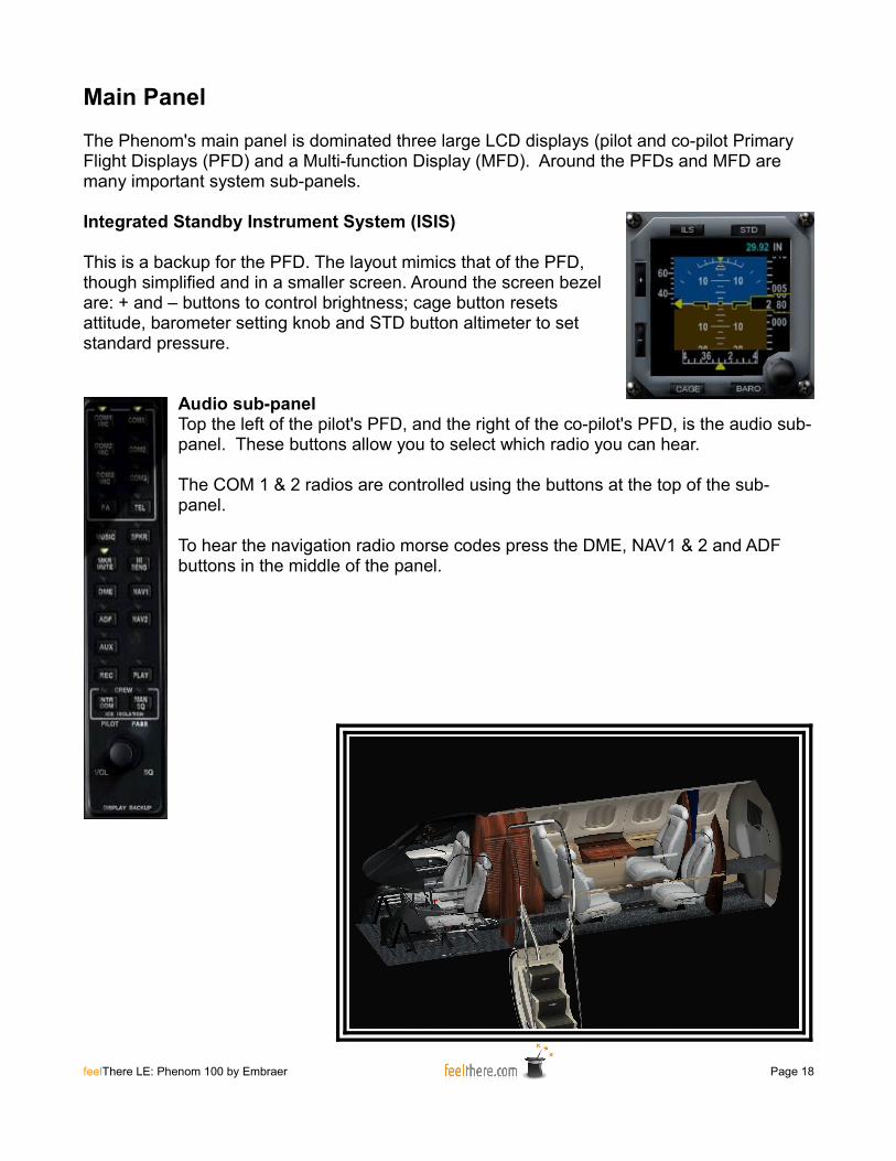
Integrated Standby Instrument System (ISIS)
This is a backup for the PFD. The layout mimics that of the PFD, though simplified and in a smaller screen. Around the screen bezel are: + and – buttons to control brightness; cage button resets attitude, barometer setting knob and STD button altimeter to set standard pressure.
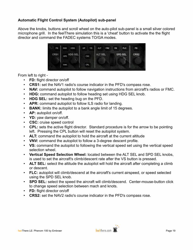
Audio sub-panelTop the left of the pilot's PFD, and the right of the co-pilot's PFD, is the audio sub-panel. These buttons allow you to select which radio you can hear.
The COM 1 & 2 radios are controlled using the buttons at the top of the sub-panel.
To hear the navigation radio morse codes press the DME, NAV1 & 2 and ADF buttons in the middle of the panel.
feelThere LE: Phenom 100 by Embraer Page 18
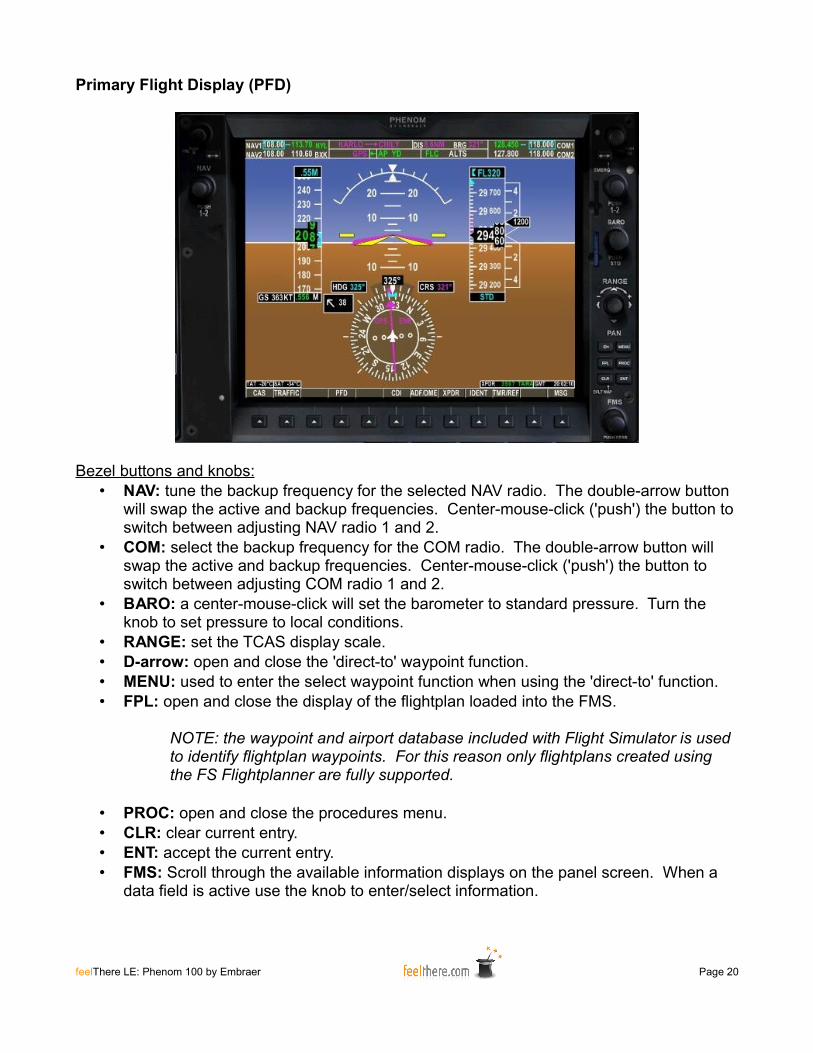
Automatic Flight Control System (Autopilot) sub-panel
Above the knobs, buttons and scroll wheel on the auto-pilot sub-panel is a small silver colored microphone grill. In the feelThere simulation this is a 'cheat' button to activate the the flight director and command the FADEC systems TO/GA modes.
From left to right -• FD: flight director on/off• CRS1: set the NAV1 radio's course indicator in the PFD's compass rose.• NAV: command autopilot to follow navigation instructions from aircraft's radios or FMC.• HDG: command autopilot to follow heading set using HDG SEL knob.• HDG SEL: set the heading bug on the PFD.• APR: command autopilot to follow ILS radio for landing.• BANK: limits the autopilot to a bank angle limit of 15 degrees.• AP: autopilot on/off.• YD: yaw damper on/off.• CSC: cruise speed control• CPL: sets the active flight director. Standard procedure is for the arrow to be pointing
left. Pressing the CPL button will reset the autopilot system.• ALT: command the autopilot to hold the aircraft at the current altitude• VNV: command the autopilot to follow a 3-degree descent profile.• VS: command the autopilot to following the vertical speed set using the vertical speed
selection wheel.• Vertical Speed Selection Wheel: located between the ALT SEL and SPD SEL knobs,
is used to set the aircraft's climb/descent rate after the VS button is pressed.• ALT SEL: select the altitude the autopilot will hold the aircraft after completing a climb
or descent.• FLC: autopilot will climb/descend at the aircraft's current airspeed, or speed selected
using the SPD SEL knob.• SPD SEL: select the speed the aircraft will climb/descend. Center-mouse-button click
to change speed selection between mach and knots.• FD: flight director on/off• CRS2: set the NAV2 radio's course indicator in the PFD's compass rose.
feelThere LE: Phenom 100 by Embraer Page 19
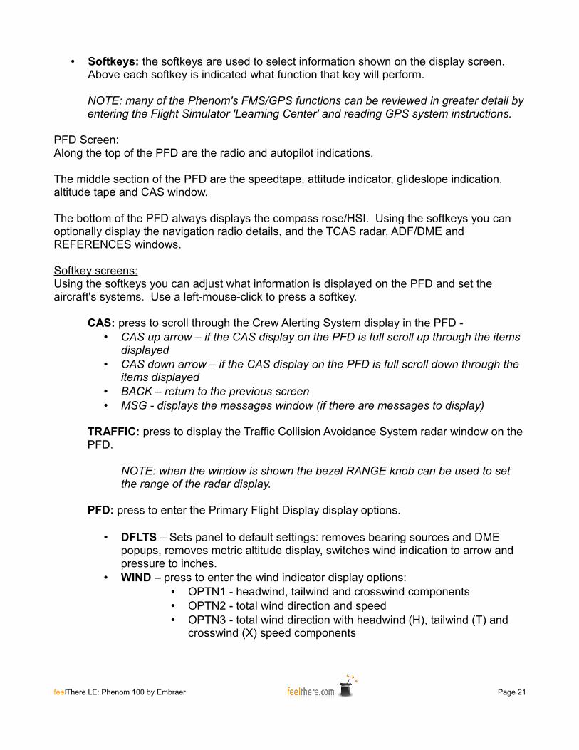
Primary Flight Display (PFD)
Bezel buttons and knobs:• NAV: tune the backup frequency for the selected NAV radio. The double-arrow button
will swap the active and backup frequencies. Center-mouse-click ('push') the button to switch between adjusting NAV radio 1 and 2.
• COM: select the backup frequency for the COM radio. The double-arrow button will swap the active and backup frequencies. Center-mouse-click ('push') the button to switch between adjusting COM radio 1 and 2.
• BARO: a center-mouse-click will set the barometer to standard pressure. Turn the knob to set pressure to local conditions.
• RANGE: set the TCAS display scale.• D-arrow: open and close the 'direct-to' waypoint function.• MENU: used to enter the select waypoint function when using the 'direct-to' function.• FPL: open and close the display of the flightplan loaded into the FMS.
NOTE: the waypoint and airport database included with Flight Simulator is used to identify flightplan waypoints. For this reason only flightplans created using the FS Flightplanner are fully supported.
• PROC: open and close the procedures menu.• CLR: clear current entry.• ENT: accept the current entry.• FMS: Scroll through the available information displays on the panel screen. When a
data field is active use the knob to enter/select information.
feelThere LE: Phenom 100 by Embraer Page 20
• Softkeys: the softkeys are used to select information shown on the display screen. Above each softkey is indicated what function that key will perform.
NOTE: many of the Phenom's FMS/GPS functions can be reviewed in greater detail by entering the Flight Simulator 'Learning Center' and reading GPS system instructions.
PFD Screen:Along the top of the PFD are the radio and autopilot indications.
The middle section of the PFD are the speedtape, attitude indicator, glideslope indication, altitude tape and CAS window.
The bottom of the PFD always displays the compass rose/HSI. Using the softkeys you can optionally display the navigation radio details, and the TCAS radar, ADF/DME and REFERENCES windows.
Softkey screens:Using the softkeys you can adjust what information is displayed on the PFD and set the aircraft's systems. Use a left-mouse-click to press a softkey.
CAS: press to scroll through the Crew Alerting System display in the PFD -• CAS up arrow – if the CAS display on the PFD is full scroll up through the items
displayed• CAS down arrow – if the CAS display on the PFD is full scroll down through the
items displayed• BACK – return to the previous screen• MSG - displays the messages window (if there are messages to display)
TRAFFIC: press to display the Traffic Collision Avoidance System radar window on the PFD.
NOTE: when the window is shown the bezel RANGE knob can be used to set the range of the radar display.
PFD: press to enter the Primary Flight Display display options.
• DFLTS – Sets panel to default settings: removes bearing sources and DME popups, removes metric altitude display, switches wind indication to arrow and pressure to inches.
• WIND – press to enter the wind indicator display options:• OPTN1 - headwind, tailwind and crosswind components• OPTN2 - total wind direction and speed• OPTN3 - total wind direction with headwind (H), tailwind (T) and
crosswind (X) speed components
feelThere LE: Phenom 100 by Embraer Page 21
• OFF – remove the wind indicator display from the PFD.• BACK – return to the previous screen.• MSG - displays the messages window (if there are messages to
display)
• DME1 – press to have the NAV1 radio information display on the PFD.• BRG1 – press to have bearing and distance information displayed on the PFD.
First click shows NAV1 radio, second ADF, third GPS, and fourth click removes indication.
• HSI – disabled• BRG2 – press to have bearing and distance information displayed on the PFD.
First click shows NAV2 radio, second ADF, third GPS, and fourth click removes indication.
• DME2 - press to have the NAV2 radio information display on the PFD.• ALT UNT – press to adjust the PFD altitude displays:
• METERS – adds metric altitude indications to the PFD.• IN – sets altimeter to display the BARO setting as inches of
mercury.• HPA – display the BARO setting as hectopacals.• STD – sets the altimeter to standard pressure.• BACK – return to the previous screen.• MSG - displays the messages window (if there are messages to
display)
• FD – press to adjust the flight director indication on the PFD:• SNG CUE – a triangle shaped pointer• X-POINT – an cross shaped pointer• BACK – return to the previous screen.• MSG – displays the messages window (if there are messages to
display).
• BACK – return to the previous screen• MSG - displays the messages window (if there are messages to display)
CDI – each push of the softkey changes the primary navigation source used by the autopilot. The source indication will change on the compass rose and on the annunciator.
• MAGENTA indication – primary source is the GPS/FMC• GREEN indication – source is the NAV radios
ADF/DME – displays the ADF/DME turning window on the PFD. Using the FMS knob you can adjust the ADF frequency and set the ADF mode.
XPDR – press to enter the transponder control options.• MODE – press to enter the mode control options:
feelThere LE: Phenom 100 by Embraer Page 22
• STBY – XPDR in standby mode.• ON – XPDR is on.• ALT – XPDR is on and transmits altitude information• TA ONLY - only the Traffic Advisory function is operational• TA/RA - traffic and resolution advisory systems are on• BACK – return to the previous screen.• MSG - displays the messages window (if there are messages to
display)
• TCAS – press to enter the Traffic Collision Avoidance System display options:• REL – traffic altitude is shown relative to the Phenom• ABS – traffic's actual altitude is show• ALT RING -
• ABOVE – system focus on aircraft above Phenom's altitude
• NORMAL – system looks above and below for conflicting aircraft
• BELOW – system focus is on aircraft below the Phenom's altitude.
• UNREST - all the traffic shown regardless of relative altitude
• BACK – return to the previous screen.• MSG - displays the messages window (if there are
messages to display)
• TEST – run a system test of the TCAS system.• BACK – return to the previous screen.• MSG - displays the messages window (if there are messages to
display)
NOTE: the TRAFFIC softkey must be pressed in order for the radar to show on the PFD.
• CODE – when pressed you will be able to set the transponder code• numbers 0-9 – set the transponder code using these keys.• IDENT – transmit transponder code when requested by ATC.• BKSP – deletes the last digit entered when entering a transponder
code.• BACK – return to the previous screen.• MSG - displays the messages window (if there are messages to
display)
NOTE: if no activity occurs on this screen for more than 10 seconds the softkeys will revert back to the TCAS menu.
feelThere LE: Phenom 100 by Embraer Page 23
• IDENT - transmit transponder code when requested by ATC.• BACK – return to the previous screen.• MSG - displays the messages window (if there are messages to display)
IDENT – transmit transponder code when requested by ATC.
TMR/REF – displays the timer and reference speeds control window on the PFD. Place the mouse pointer on upper half of the FMS knob and left-mouse-click or scroll the center mouse wheel to select the item to be adjusted:
• TIMER - press the ENT button to start, stop and reset the timer.• V-SPEEDS - place the mouse pointer on lower half of the FMS knob and left-
mouse-click or scroll the center mouse wheel to adjust the v-speeds. Place the mouse pointer on lower half of the FMS knob and left-mouse-click or scroll the center mouse wheel to display (ON) or remove (OFF) the v-speed from the PFD speedtape.
• MINIMUMS - place the mouse pointer on lower half of the FMS knob and left-mouse-click or scroll the center mouse wheel set the system used to indicate the minimum landing decision high*. MINIMUMS must be set to BARO or RAD ALT for the altitude selection field to be active.
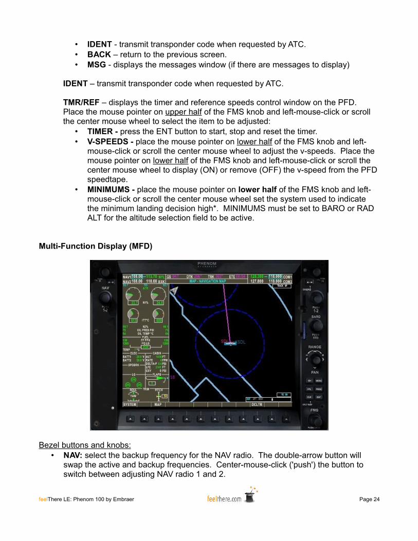
Multi-Function Display (MFD)
Bezel buttons and knobs:• NAV: select the backup frequency for the NAV radio. The double-arrow button will
swap the active and backup frequencies. Center-mouse-click ('push') the button to switch between adjusting NAV radio 1 and 2.
feelThere LE: Phenom 100 by Embraer Page 24

• COM: select the backup frequency for the COM radio. The double-arrow button will swap the active and backup frequencies. Center-mouse-click ('push') the button to switch between adjusting COM radio 1 and 2.
• BARO: a center-mouse-click will set the barometer to standard pressure. Turn the knob to set pressure to local conditions.
• RANGE: set the map display scale.• D-arrow: open and close the 'direct-to' waypoint function.• MENU: used in conjunction with the 'direct-to' waypoint function.• FPL: open and close the flightplan loaded into the FMS.• PROC: open and close the procedures menu.• CLR: clear current entry.• ENT: accept the current entry.• FMS: Scroll through the available information displays on the panel screen. When a
data field is active use the knob to enter/select information.• Softkeys: the softkeys are used to select information shown on the display screen.
Above each softkey is indicated what function that key will perform.
MFD Screen:The mechanical system summary is along the left side of the screen. To the right is the navigation map. Along the top are the radio settings, and status of the current flight (ground speed, flight track and ETE).
Softkey screens:
SYSTEM: press to enter the system setting options.
• ENG SET: press to enter thrust settings.• CON – commands the FADEC to allow/command maximum
continuous thrust.• CLB – commands the FADEC to allow/command maximum climb
thrust.• ATR ON – enables Automatic Thrust Reserve. In the event of a
single engine failure ATR commands extra thrust on the operating engine.
• ATR OFF – disables Automatic Thrust Reserve.• BACK – return to the previous options or screen.
• LFE: press to enter landing airfield elevation.• FMS LFE – this is the default setting. The cabin pressurization
schedule will be set based on the destination airport set in the flightplan loaded into the FMC.
• +/- 500 and 50 FT – set the elevation for the arrival airport. The altitude will be shown in the CABIN section of the system summary information on the MFD.
• ACCEPT – activate the setting selected.
feelThere LE: Phenom 100 by Embraer Page 25
• BACK – without saving the setting selected return to the previous screen.
MAP: press to set the map display options:
• TOPO:set the map display to topographic view.• BACK: return to the previous screen.
The FSX version of the Phenom supports the following additional MAP functions:
• TRAFFIC – set the map to display local air traffic.• AIRWAY – set the map to display airways.
DCLTR: press to progressively de-clutter the map display.DCLTR: repopulates the mapDCTLR-1: removes VORsDCTLR-2: removes airport runwaysDCTLR-3: removes all data but the active flightplan
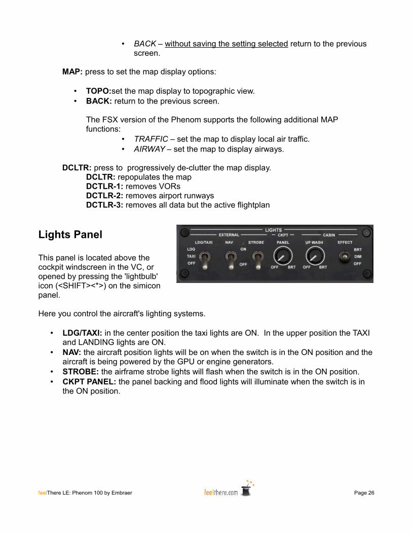
Lights Panel
This panel is located above the cockpit windscreen in the VC, or opened by pressing the 'lightbulb' icon (<SHIFT><*>) on the simicon panel.
Here you control the aircraft's lighting systems.
• LDG/TAXI: in the center position the taxi lights are ON. In the upper position the TAXI and LANDING lights are ON.
• NAV: the aircraft position lights will be on when the switch is in the ON position and the aircraft is being powered by the GPU or engine generators.
• STROBE: the airframe strobe lights will flash when the switch is in the ON position.• CKPT PANEL: the panel backing and flood lights will illuminate when the switch is in
the ON position.
feelThere LE: Phenom 100 by Embraer Page 26
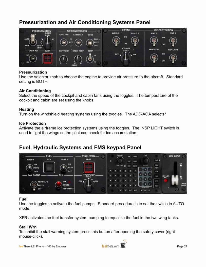
Pressurization and Air Conditioning Systems Panel
PressurizationUse the selector knob to choose the engine to provide air pressure to the aircraft. Standard setting is BOTH.
Air ConditioningSelect the speed of the cockpit and cabin fans using the toggles. The temperature of the cockpit and cabin are set using the knobs.
HeatingTurn on the windshield heating systems using the toggles. The ADS-AOA selects*
Ice ProtectionActivate the airframe ice protection systems using the toggles. The INSP LIGHT switch is used to light the wings so the pilot can check for ice accumulation.
Fuel, Hydraulic Systems and FMS keypad Panel
FuelUse the toggles to activate the fuel pumps. Standard procedure is to set the switch in AUTO mode.
XFR activates the fuel transfer system pumping to equalize the fuel in the two wing tanks.
Stall WrnTo inhibit the stall warning system press this button after opening the safety cover (right-mouse-click).
feelThere LE: Phenom 100 by Embraer Page 27
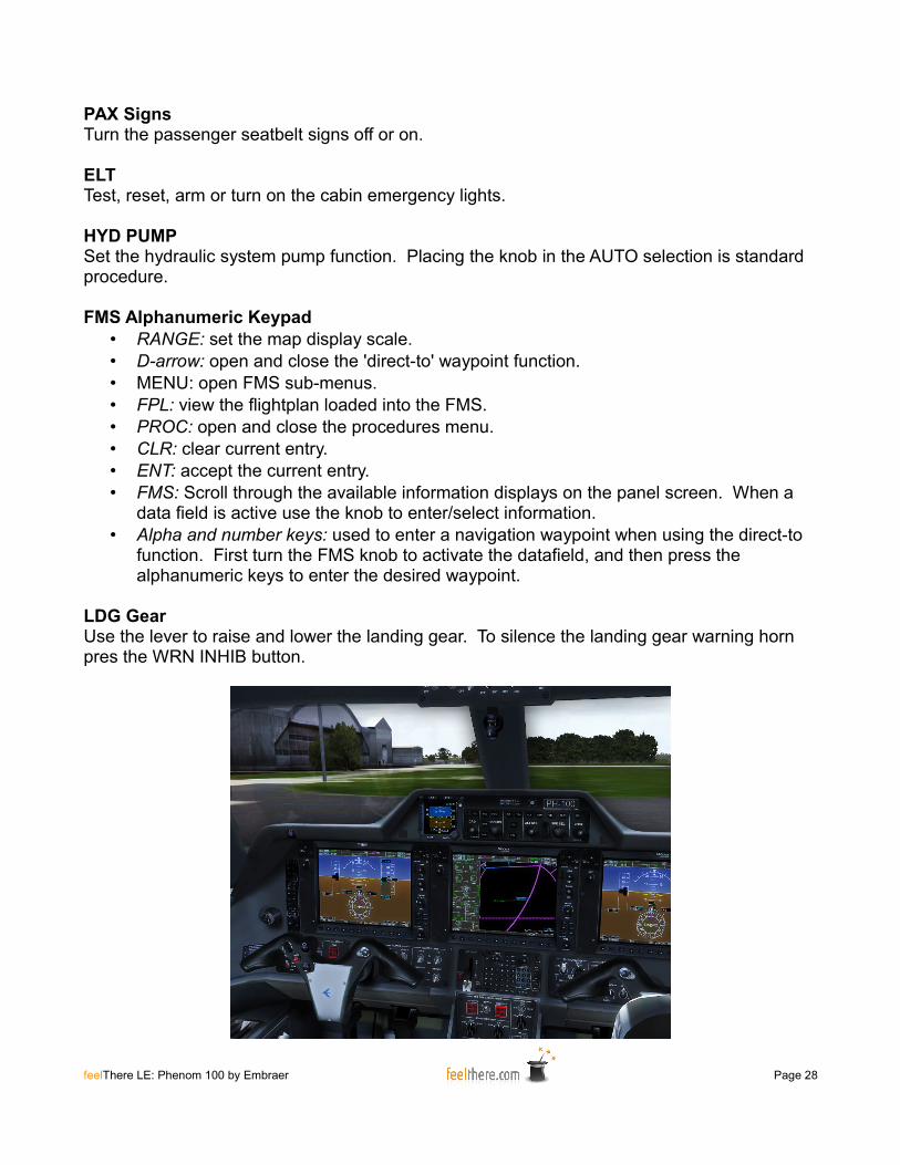
PAX SignsTurn the passenger seatbelt signs off or on.
ELTTest, reset, arm or turn on the cabin emergency lights.
HYD PUMPSet the hydraulic system pump function. Placing the knob in the AUTO selection is standard procedure.
FMS Alphanumeric Keypad• RANGE: set the map display scale.• D-arrow: open and close the 'direct-to' waypoint function.• MENU: open FMS sub-menus.• FPL: view the flightplan loaded into the FMS.• PROC: open and close the procedures menu.• CLR: clear current entry.• ENT: accept the current entry.• FMS: Scroll through the available information displays on the panel screen. When a
data field is active use the knob to enter/select information.• Alpha and number keys: used to enter a navigation waypoint when using the direct-to
function. First turn the FMS knob to activate the datafield, and then press the alphanumeric keys to enter the desired waypoint.
LDG GearUse the lever to raise and lower the landing gear. To silence the landing gear warning horn pres the WRN INHIB button.
feelThere LE: Phenom 100 by Embraer Page 28

Electrical, Fire Extinguisher and Engine Start/Stop Panel
This sub-panel is located below the pilot's side window in the VC, or opened by pressing the 'electric plug' icon (<SHIFT><*>) on the simicon panel.
Gen 1/2Set the toggles to put on-line the engine 1 and 2 generators. Standard setting is AUTO.
GPUWhen the parking brake has been set for approximately 30 seconds to one minute the Ground Power Unit will be available to power the aircraft. Press this button to connect the GPU to the aircraft's electrical system.
Bus TieUse the knob to set the electrical bus that is powering the aircraft. Standard setting is AUTO.
Batt 1/2Use the toggles to connect the batteries to the aircraft's electrical system.
Elec EmerPowers only the aircraft's vital systems in the event of an electrical failure.
Eng Fire ExtinguisherSHUTOFF 1/2 – in the event of an engine fire, after opening the safety cover, press the button to initiate an emergency shutdown of the selected engine.BOTTLE – in the event of an engine fire set the switch to DISH to activate the fire extinguisher system.
Eng Start/StopThe engine start and stop functions are fully automatic. To start an engine turn the knob to the START position and release. During flight operations the start/stop knobs should be in the RUN position. To shut down an engine turn the knob to the STOP position.
feelThere LE: Phenom 100 by Embraer Page 29
Eng IgnitionSet the engine ignition system using these toggle switches. Standard procedure is to set the ignition system to AUTO.
TrimThe YAW and ROLL selectors are use if it is necessary to trim the aircraft's flight control surfaces.
Pitch BKPSet the pitch trim using this toggle switch.
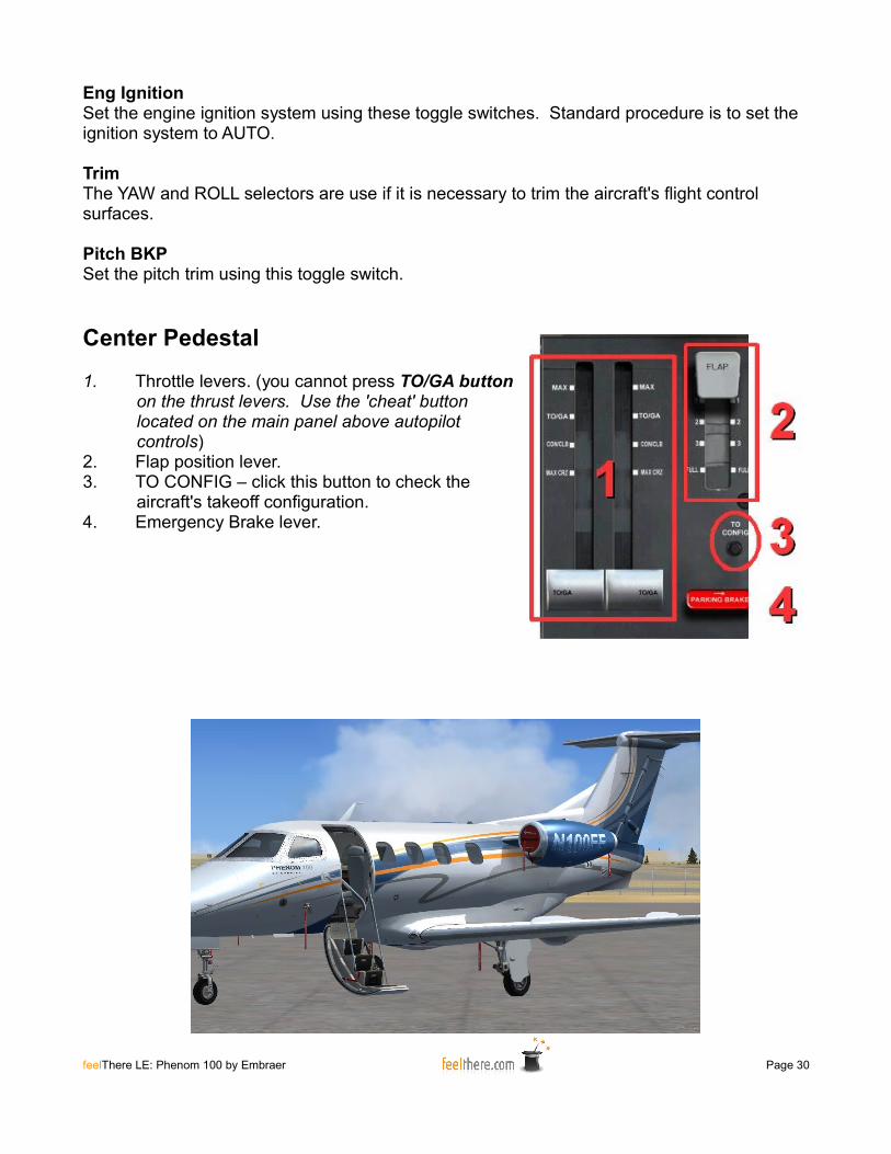
Center Pedestal
1. Throttle levers. (you cannot press TO/GA button on the thrust levers. Use the 'cheat' button located on the main panel above autopilot controls)
2. Flap position lever.3. TO CONFIG – click this button to check the
aircraft's takeoff configuration.4. Emergency Brake lever.
feelThere LE: Phenom 100 by Embraer Page 30
FULL AUTHORITY DIGITAL ELECTRONIC CONTROL (FADEC)
Each engine is controlled by two FADECS which control fuel flow to the engines to reach the required fan speeds.
ENGINE STARTEngine start is initiated by turning the associated engine Start/Stop knob to the START position. There is no APU on the Phenom. Engine start is electric and uses the aircraft's batteries or GPU.
The FADEC is responsible for the automatic engine startup and completing the startup cycle.
TAKEOFF AND IN-FLIGHT THRUSTSimulation of the throttle control in-flight by the FADEC and autothrottle CSC system requires that your joystick/yoke/throttle quadrant thrust lever be in the full-forward position after engine engine run-up prior to takeoff.
The Phenom does not have a traditional autothrottle system. When in level flight at cruise altitude the CSC button on the glareshield will hold the aircraft at the speed set using the SPD knob. CSC cannot be used during climb or descent.
LANDING THRUSTDescent, approach and landing thrust is controlled by the pilot.
ENGINE SHUTDOWNEngine shutdown is initiated by using the Engine Start/Stop knob with the Thrust Leverpositioned at IDLE (users with throttle control, make sure the throttle is calibrated otherwisehit F1 to bring the engines to complete idle). Once at your assigned parking location the engines must be cooled with the throttles in the idle position for two minutes before they are shutdown. The engines will only shutdown when the throttles are in the idle position.
feelThere LE: Phenom 100 by Embraer Page 31
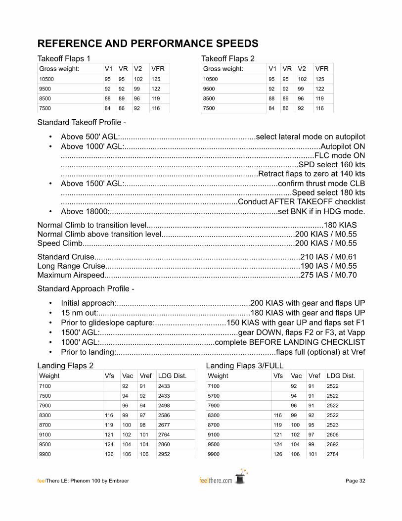
REFERENCE AND PERFORMANCE SPEEDSTakeoff Flaps 1Gross weight: V1 VR V2 VFR10500 95 95 102 125
9500 92 92 99 122
8500 88 89 96 119
7500 84 86 92 116
Takeoff Flaps 2Gross weight: V1 VR V2 VFR10500 95 95 102 125
9500 92 92 99 122
8500 88 89 96 119
7500 84 86 92 116
Standard Takeoff Profile -
• Above 500' AGL:..............................................................select lateral mode on autopilot• Above 1000' AGL:..........................................................................................Autopilot ON
....................................................................................................................FLC mode ON
.............................................................................................................SPD select 160 kts
...........................................................................................Retract flaps to zero at 140 kts• Above 1500' AGL:......................................................................confirm thrust mode CLB
..........................................................................................................Speed select 180 kts
.................................................................................Conduct AFTER TAKEOFF checklist• Above 18000:.............................................................................set BNK if in HDG mode.
Normal Climb to transition level.................................................................................180 KIASNormal Climb above transition level.............................................................200 KIAS / M0.55Speed Climb.................................................................................................200 KIAS / M0.55
Standard Cruise..............................................................................................210 IAS / M0.61Long Range Cruise.........................................................................................190 IAS / M0.55Maximum Airspeed..........................................................................................275 IAS / M0.70
Standard Approach Profile -
• Initial approach:.............................................................200 KIAS with gear and flaps UP• 15 nm out:......................................................................180 KIAS with gear and flaps UP• Prior to glideslope capture:................................150 KIAS with gear UP and flaps set F1• 1500' AGL:...............................................................gear DOWN, flaps F2 or F3, at Vapp• 1000' AGL:.....................................................complete BEFORE LANDING CHECKLIST• Prior to landing:.........................................................................flaps full (optional) at Vref
Landing Flaps 2Weight Vfs Vac Vref LDG Dist.7100 92 91 2433
7500 94 92 2433
7900 96 94 2498
8300 116 99 97 2586
8700 119 100 98 2677
9100 121 102 101 2764
9500 124 104 104 2860
9900 126 106 106 2952
Landing Flaps 3/FULLWeight Vfs Vac Vref LDG Dist.7100 92 91 2522
5700 94 91 2522
7900 96 91 2522
8300 116 99 92 2522
8700 119 100 95 2523
9100 121 102 97 2606
9500 124 104 99 2692
9900 126 106 101 2784
feelThere LE: Phenom 100 by Embraer Page 32
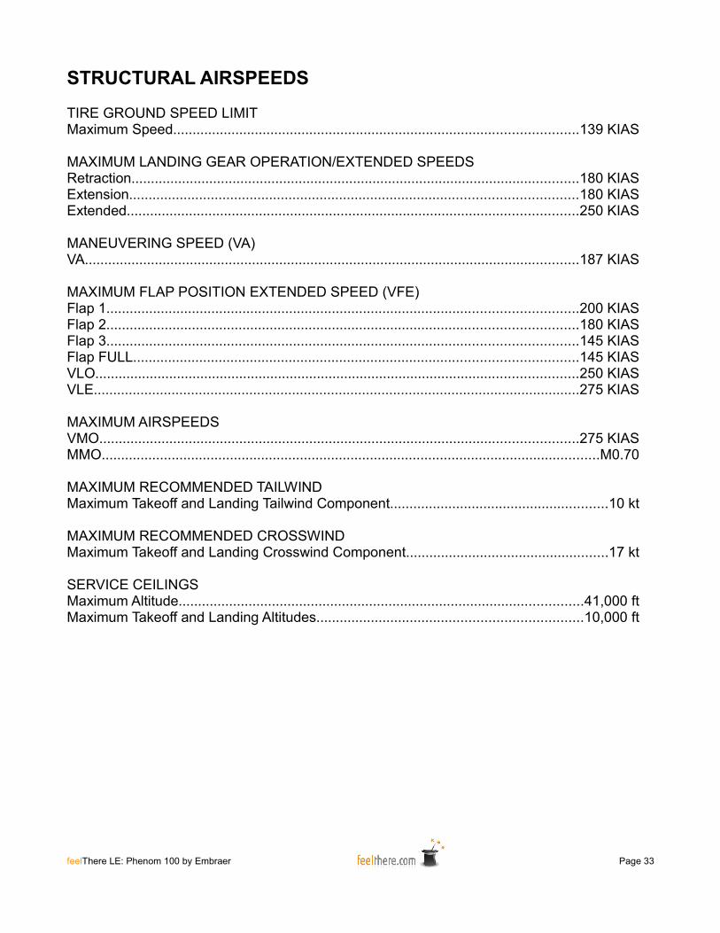
STRUCTURAL AIRSPEEDS
TIRE GROUND SPEED LIMITMaximum Speed........................................................................................................139 KIAS
MAXIMUM LANDING GEAR OPERATION/EXTENDED SPEEDSRetraction...................................................................................................................180 KIASExtension...................................................................................................................180 KIASExtended....................................................................................................................250 KIAS
MANEUVERING SPEED (VA)VA...............................................................................................................................187 KIAS
MAXIMUM FLAP POSITION EXTENDED SPEED (VFE)Flap 1.........................................................................................................................200 KIASFlap 2.........................................................................................................................180 KIASFlap 3.........................................................................................................................145 KIASFlap FULL..................................................................................................................145 KIASVLO............................................................................................................................250 KIASVLE.............................................................................................................................275 KIAS
MAXIMUM AIRSPEEDSVMO...........................................................................................................................275 KIASMMO................................................................................................................................M0.70
MAXIMUM RECOMMENDED TAILWINDMaximum Takeoff and Landing Tailwind Component........................................................10 kt
MAXIMUM RECOMMENDED CROSSWINDMaximum Takeoff and Landing Crosswind Component....................................................17 kt
SERVICE CEILINGSMaximum Altitude........................................................................................................41,000 ftMaximum Takeoff and Landing Altitudes....................................................................10,000 ft
feelThere LE: Phenom 100 by Embraer Page 33
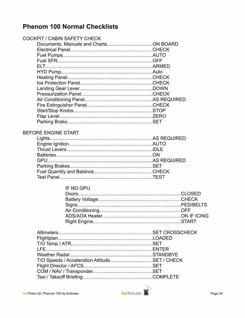
Phenom 100 Normal Checklists
COCKPIT / CABIN SAFETY CHECKDocuments, Manuals and Charts..................................ON BOARDElectrical Panel..............................................................CHECKFuel Pumps....................................................................AUTOFuel XFR........................................................................OFFELT.................................................................................ARMEDHYD Pump.....................................................................AutoHeating Panel................................................................CHECKIce Protection Panel......................................................CHECKLanding Gear Lever.......................................................DOWNPressurization Panel......................................................CHECKAir Conditioning Panel...................................................AS REQUIREDFire Extinguisher Panel.................................................CHECKStart/Stop Knobs...........................................................STOPFlap Level......................................................................ZEROParking Brake................................................................SET
BEFORE ENGINE STARTLights.............................................................................AS REQUIREDEngine Ignition...............................................................AUTOThrust Levers.................................................................IDLEBatteries.........................................................................ONGPU...............................................................................AS REQUIREDParking Brakes..............................................................SETFuel Quantity and Balance............................................CHECKTest Panel......................................................................TEST
IF NO GPUDoors.............................................................................CLOSEDBattery Voltage..............................................................CHECKSigns..............................................................................PED/BELTSAir Conditioning.............................................................OFFADS/AOA Heater...........................................................ON IF ICINGRight Engine..................................................................START
Altimeters.......................................................................SET CROSSCHECKFlightplan.......................................................................LOADEDT/O Temp / ATR.............................................................SETLFE................................................................................ENTERWeather Radar..............................................................STANDBYET/O Speeds / Acceleration Altitude................................SET / CHECKFlight Director / AFCS....................................................SETCOM / NAV / Transponder.............................................SETTaxi / Takeoff Briefing.....................................................COMPLETE
feelThere LE: Phenom 100 by Embraer Page 34
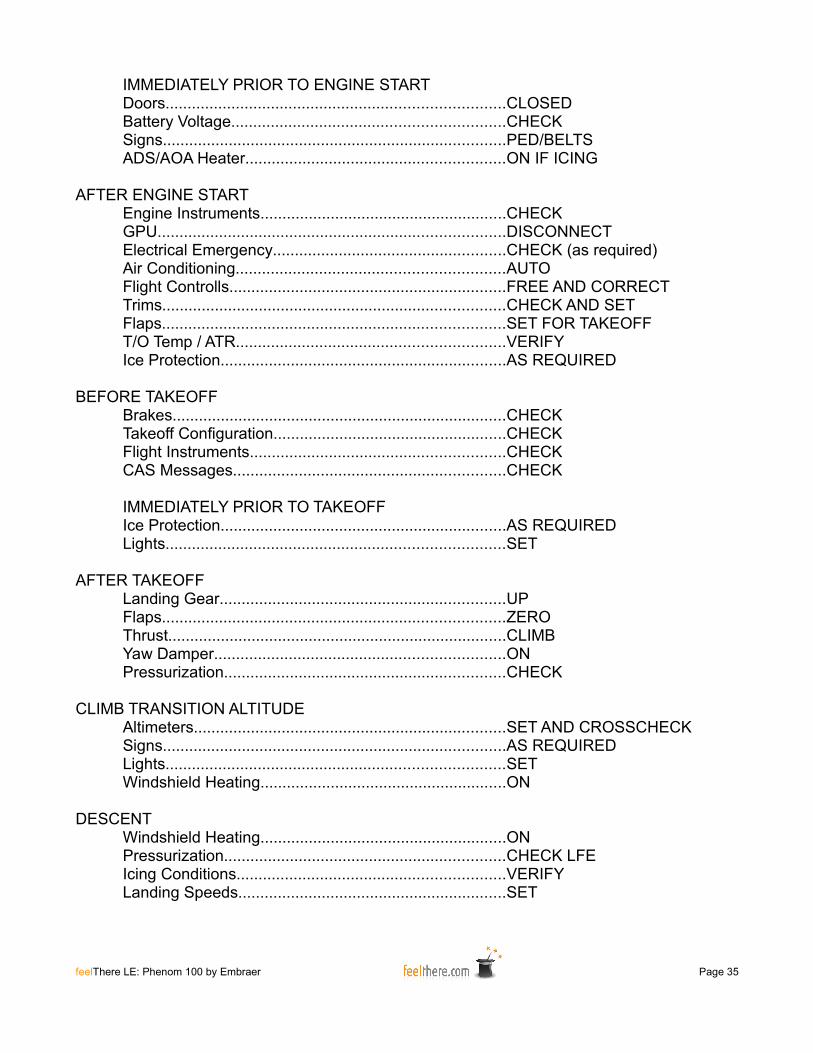
IMMEDIATELY PRIOR TO ENGINE STARTDoors.............................................................................CLOSEDBattery Voltage..............................................................CHECKSigns..............................................................................PED/BELTSADS/AOA Heater...........................................................ON IF ICING
AFTER ENGINE STARTEngine Instruments........................................................CHECKGPU...............................................................................DISCONNECTElectrical Emergency.....................................................CHECK (as required)Air Conditioning.............................................................AUTOFlight Controlls...............................................................FREE AND CORRECTTrims..............................................................................CHECK AND SETFlaps..............................................................................SET FOR TAKEOFFT/O Temp / ATR.............................................................VERIFYIce Protection.................................................................AS REQUIRED
BEFORE TAKEOFFBrakes............................................................................CHECKTakeoff Configuration.....................................................CHECKFlight Instruments..........................................................CHECKCAS Messages..............................................................CHECK
IMMEDIATELY PRIOR TO TAKEOFFIce Protection.................................................................AS REQUIREDLights.............................................................................SET
AFTER TAKEOFFLanding Gear.................................................................UPFlaps..............................................................................ZEROThrust.............................................................................CLIMBYaw Damper..................................................................ONPressurization................................................................CHECK
CLIMB TRANSITION ALTITUDEAltimeters.......................................................................SET AND CROSSCHECKSigns..............................................................................AS REQUIREDLights.............................................................................SETWindshield Heating........................................................ON
DESCENTWindshield Heating........................................................ONPressurization................................................................CHECK LFEIcing Conditions.............................................................VERIFYLanding Speeds.............................................................SET
feelThere LE: Phenom 100 by Embraer Page 35
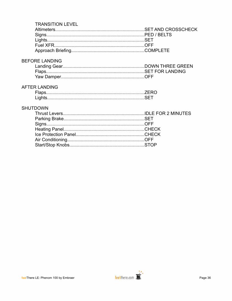
TRANSITION LEVELAltimeters.......................................................................SET AND CROSSCHECKSigns..............................................................................PED / BELTSLights.............................................................................SETFuel XFR........................................................................OFFApproach Briefing..........................................................COMPLETE
BEFORE LANDINGLanding Gear.................................................................DOWN THREE GREENFlaps..............................................................................SET FOR LANDINGYaw Damper..................................................................OFF
AFTER LANDINGFlaps..............................................................................ZEROLights.............................................................................SET
SHUTDOWNThrust Levers.................................................................IDLE FOR 2 MINUTESParking Brake................................................................SETSigns..............................................................................OFFHeating Panel................................................................CHECKIce Protection Panel......................................................CHECKAir Conditioning.............................................................OFFStart/Stop Knobs...........................................................STOP
feelThere LE: Phenom 100 by Embraer Page 36
EICAS MESSAGES
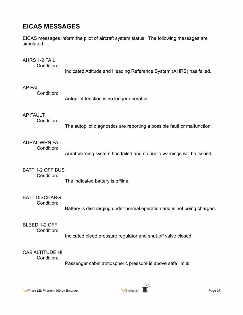
EICAS messages inform the pilot of aircraft system status. The following messages are simulated -
AHRS 1-2 FAILCondition:
Indicated Attitude and Heading Reference System (AHRS) has failed.
AP FAILCondition:
Autopilot function is no longer operative.
AP FAULTCondition:
The autopilot diagnostics are reporting a possible fault or malfunction.
AURAL WRN FAILCondition:
Aural warning system has failed and no audio warnings will be issued.
BATT 1-2 OFF BUSCondition:
The indicated battery is offline.
BATT DISCHARGCondition:
Battery is discharging under normal operation and is not being charged.
BLEED 1-2 OFFCondition:
Indicated bleed pressure regulator and shut-off valve closed.
CAB ALTITUDE HICondition:
Passenger cabin atmospheric pressure is above safe limits.
feelThere LE: Phenom 100 by Embraer Page 37
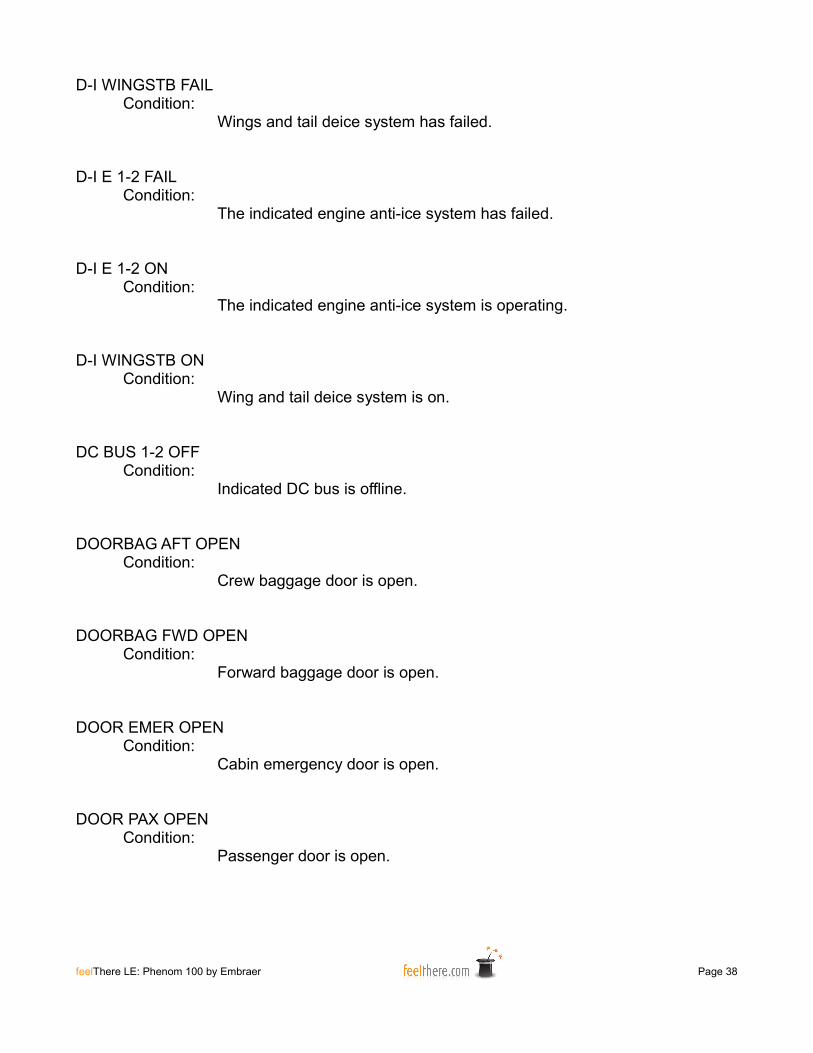
D-I WINGSTB FAILCondition:
Wings and tail deice system has failed.
D-I E 1-2 FAILCondition:
The indicated engine anti-ice system has failed.
D-I E 1-2 ONCondition:
The indicated engine anti-ice system is operating.
D-I WINGSTB ONCondition:
Wing and tail deice system is on.
DC BUS 1-2 OFFCondition:
Indicated DC bus is offline.
DOORBAG AFT OPENCondition:
Crew baggage door is open.
DOORBAG FWD OPENCondition:
Forward baggage door is open.
DOOR EMER OPENCondition:
Cabin emergency door is open.
DOOR PAX OPENCondition:
Passenger door is open.
feelThere LE: Phenom 100 by Embraer Page 38
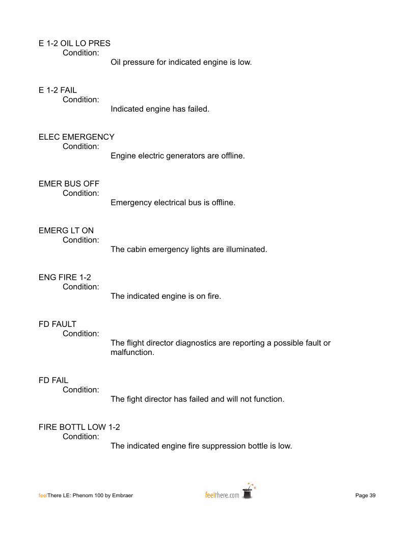
E 1-2 OIL LO PRESCondition:
Oil pressure for indicated engine is low.
E 1-2 FAILCondition:
Indicated engine has failed.
ELEC EMERGENCYCondition:
Engine electric generators are offline.
EMER BUS OFFCondition:
Emergency electrical bus is offline.
EMERG LT ONCondition:
The cabin emergency lights are illuminated.
ENG FIRE 1-2Condition:
The indicated engine is on fire.
FD FAULTCondition:
The flight director diagnostics are reporting a possible fault or malfunction.
FD FAILCondition:
The fight director has failed and will not function.
FIRE BOTTL LOW 1-2Condition:
The indicated engine fire suppression bottle is low.
feelThere LE: Phenom 100 by Embraer Page 39
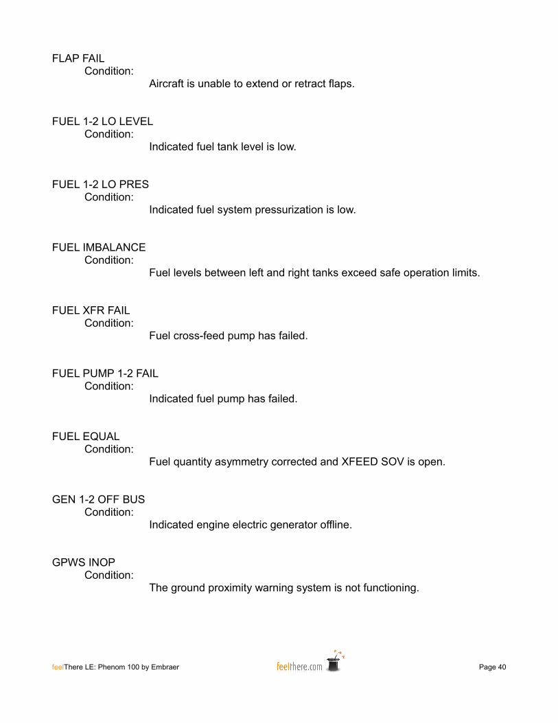
FLAP FAILCondition:
Aircraft is unable to extend or retract flaps.
FUEL 1-2 LO LEVELCondition:
Indicated fuel tank level is low.
FUEL 1-2 LO PRESCondition:
Indicated fuel system pressurization is low.
FUEL IMBALANCECondition:
Fuel levels between left and right tanks exceed safe operation limits.
FUEL XFR FAILCondition:
Fuel cross-feed pump has failed.
FUEL PUMP 1-2 FAILCondition:
Indicated fuel pump has failed.
FUEL EQUALCondition:
Fuel quantity asymmetry corrected and XFEED SOV is open.
GEN 1-2 OFF BUSCondition:
Indicated engine electric generator offline.
GPWS INOPCondition:
The ground proximity warning system is not functioning.
feelThere LE: Phenom 100 by Embraer Page 40
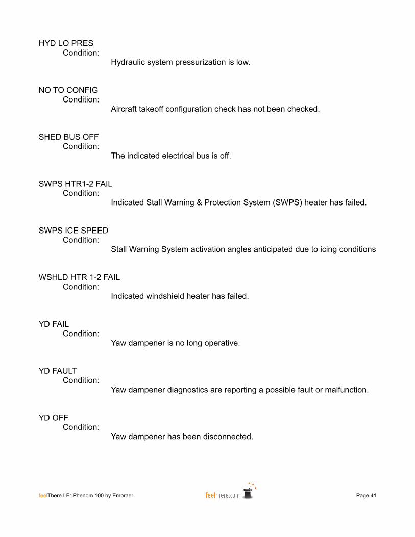
HYD LO PRESCondition:
Hydraulic system pressurization is low.
NO TO CONFIGCondition:
Aircraft takeoff configuration check has not been checked.
SHED BUS OFFCondition:
The indicated electrical bus is off.
SWPS HTR1-2 FAILCondition:
Indicated Stall Warning & Protection System (SWPS) heater has failed.
SWPS ICE SPEEDCondition:
Stall Warning System activation angles anticipated due to icing conditions
WSHLD HTR 1-2 FAILCondition:
Indicated windshield heater has failed.
YD FAILCondition:
Yaw dampener is no long operative.
YD FAULTCondition:
Yaw dampener diagnostics are reporting a possible fault or malfunction.
YD OFFCondition:
Yaw dampener has been disconnected.
feelThere LE: Phenom 100 by Embraer Page 41
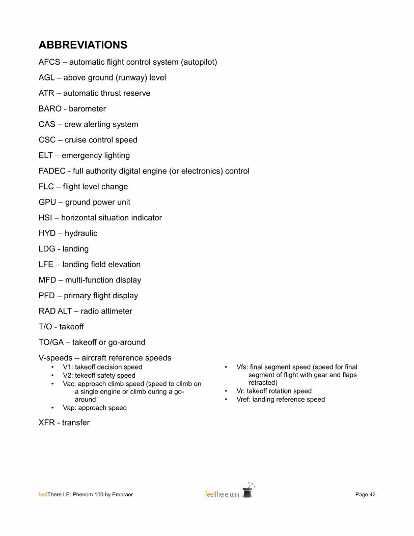
ABBREVIATIONSAFCS – automatic flight control system (autopilot)
AGL – above ground (runway) level
ATR – automatic thrust reserve
BARO - barometer
CAS – crew alerting system
CSC – cruise control speed
ELT – emergency lighting
FADEC - full authority digital engine (or electronics) control
FLC – flight level change
GPU – ground power unit
HSI – horizontal situation indicator
HYD – hydraulic
LDG - landing
LFE – landing field elevation
MFD – multi-function display
PFD – primary flight display
RAD ALT – radio altimeter
T/O - takeoff
TO/GA – takeoff or go-around
V-speeds – aircraft reference speeds• V1: takeoff decision speed• V2: tekeoff safety speed• Vac: approach climb speed (speed to climb on
a single engine or climb during a go-around
• Vap: approach speed
• Vfs: final segment speed (speed for final segment of flight with gear and flaps retracted)
• Vr: takeoff rotation speed• Vref: landing reference speed
XFR - transfer
feelThere LE: Phenom 100 by Embraer Page 42

CREDITS, RESOURCES AND COPYRIGHTSProducer: Victor Racz
Lead Programmer: Alex Koshterek
Flight Dynamics: Alex KoshterekShane Olguin
2D Art: Alexandr EmelyanovVyacheslav Fomin
3D Art: Alexandr Emelyanov
Animation Alexandr EmelyanovVyacheslav FominDmitriy B. Shtefanov
Porting: Vyacheslav FominDmitriy B. Shtefanov
Manual: W. David Scobie
Testers: Neil PerrinW. David Scobie
First Officer Voice: W. David Scobie
Sound: Turbine Sound Studios
Special thanks: Empresa Brasileira de Aeronáutica, S. A. (BrazilianAeronautics Company, Inc.; Embraer)
Phenom SUPPORT:feelThere forum (registration required): http://forum.iemit.com
RESOURCES:The Embraer Company: http://www.embraer.com
TSS: http://www.turbinesoundstudios.com
United States FederalAviation AdministrationAirport Charts: http://aeronav.faa.gov/index.asp?xml=aeronav/applications/d_tpp
feelThere LE: Phenom 100 by Embraer Page 43

COPYRIGHT
All photographs and graphics are owned by feelThere except as noted.
All referenced products, trademarks and brand names are products, trademarks or registered trademarks of the respective owners.
FeelThere and associated logos are registered trademarks.
Disclaimer: at the time of publication all information in this manual and links to external resources are correct to the best of the development team's knowledge.
The airport charts included with this software are out-of-date and not to be used for real world aviation. The airport, departure and arrival charts provided with this software are for entertainment purposes only. The charts were published by the United State Federal Aviation Administration (FAA) and are in the public domain and not copyright protected. The FAA does not endorse or recommend a private industry product.
The use of this product is restricted to the private domain. Usage of this product for any professional or commercial activity is strictly forbidden. For professional use of the product contact feelThere, Inc. at [email protected]
The code used in feelThere's products may under no circumstances be decompiled or used for any other purposes without the expressed written permission of feelThere, Inc.
Additional responsibilities, restrictions and copyrights are outlined in the End User License Agreement (EULA) provided when the software was installed.
2011 - ALL RIGHTS RESERVED
Version 1.0
feelThere LE: Phenom 100 by Embraer Page 44