phenomenological understanding of poro-elasticity via the micro- … · micro-mechanics basis of...
TRANSCRIPT
Micro-Mechanics Basis of Poro-Elasticity
– 1 –
1 Phenomenological Understanding of Poro-Elasticity via the Micro-
2 Mechanics of a Simple Digital-Rock Model
3 Author: Gary D. Couples
4 Address: Institute of Petroleum Engineering, Heriot-Watt University, Edinburgh EH14 4AS
5 (Scotland, UK), ORCID: 0000-0001-6039-6973, email: [email protected]
6 ABSTRACT
7 Poro-elasticity is a material concept that expresses the reversible, macro-scale process
8 interactions that occur in a porous material, such as rocks. These process interactions take
9 place between the pore fluids, and the rock framework (or ‘skeleton’) which contains the pores.
10 The phenomenological basis of poro-elasticity is examined via a micro-mechanics analysis, using
11 a simplified digital-rock model that consists of solid elements in a lattice arrangement, and
12 which hosts a well-connected, lattice-like network of simply-shaped pore elements. The quasi-
13 static poro-mechanical bulk response of this model is defined fully by closed-form equations
14 that provide clear understanding of the process interactions, and which allow key effects to be
15 identified. Several external boundary conditions (non-isotropic strain and stress) are analyzed,
16 with drained and un-drained pore-fluid conditions, along with arbitrary pore pressure states.
17 The calculated responses of the pore-scale model, when translated into continuum-scale
18 equivalent behaviors, indicate significant problems with the existing theories of poro-elasticity
19 that are rooted in an enriched-continuum perspective. Specifically, the results show that the
Page 1 of 96 Geophysics Manuscript, Accepted Pending: For Review Not Production
Micro-Mechanics Basis of Poro-Elasticity
– 2 –
20 principle of effective stress (and the Biot coefficient alpha) is wrongly attributed to a deficiency
21 in the role of pore pressure. Instead, the micro-mechanics-based phenomenological
22 understanding identifies the change of effective stress, in a characteristically-confined setting,
23 as being the result of changes in the stress components, with a key dependency on the specifics
24 of the far-field constraints. Poro-elasticity is thus not a material characteristic; instead, it is a
25 description of a non-linear system operating at the pore scale. The analysis reveals a
26 discrepancy between the stress states within the model domain and the external stress state.
27 This yet remains to be addressed, in order to translate the micro-scale behavior into an
28 equivalent material law. (277 words)
29 Keywords: poro-elasticity, micro-mechanics, upscaling, digital rock
30
31 INTRODUCTION
32 When Biot (1941) undertook his seminal analysis, to create his process model for the
33 physics of soil/rock consolidation (in parallel with developments of constitutive relationships,
34 eg Terzaghi 1943), he adopted the conceptual framework of continuum principles, and
35 imagined that a soil or rock can be treated as an elastic solid that is slightly disrupted by the
36 presence of connected, fluid-filled holes. Biot assumed that the solid framework (‘skeleton’)
37 and pore fluid interact in simple ways that allow their effects to be separated, and that the bulk
38 response is determined as a linear combination of those effects, based on volume fractions. He
39 expressed his proposed model by scalars that represent the volumetric strain of the bulk
Page 2 of 96Geophysics Manuscript, Accepted Pending: For Review Not Production

Micro-Mechanics Basis of Poro-Elasticity
– 3 –
40 sample, , and the volumetric strain of the pore fluid, , with these being functions of stress 𝜖 𝛾
41 and pressure:
42 , (1a)𝜖 = 𝐴1𝜎 + 𝐴2𝑃
43 , (1b)𝛾 = 𝐴3𝜎 + 𝐴4𝑃
44 where is the stress, and is the fluid pressure (both figured as positive for compressive stress 𝜎 𝑃
45 states and fluid pressures). By assuming that the deviatoric parts of the stress and strain
46 tensors behave in an ideal elastic fashion, and with no dependence on the fluid pressure, the
47 definition of (Equations 1a,b) can be taken to be a scalar, the mean stress. Via this idea, the 𝜎
48 coefficients and are identified as the reciprocals of the bulk modulus of the solid, and of 𝐴1 𝐴4
49 the fluid, respectively, which are well-understood parameters from continuum descriptions.
50 In order to give physical meaning to the other two coefficients, which express
51 contributions from process interactions, Biot adopts the principle of virtual work, denoted by 𝑊
52 , to derive a separate relationship between the parameters. Because of the reversibility implied
53 by the assumption of linearity and separability of the process interactions, the expression for
54 virtual work is:
55 , (2)𝑑𝑊 = 𝜎𝑑𝜀 +𝑃𝑑𝛾 = 𝜀𝑑𝜎 +𝛾𝑑𝑃
56 (where the double over-bar indicates tensors and implies the usual tensor algebra). Biot (1941)
57 argues, because of reversibility (and hence conservation), that , and thus that the 𝑑𝑊 ≡ 0
58 coefficients and (Equations 1a,b) must be identical. This inference leads to the conclusion 𝐴2 𝐴3
59 that finding the value of this/these coefficient(s) is the only remaining task to transform a
Page 3 of 96 Geophysics Manuscript, Accepted Pending: For Review Not Production

Micro-Mechanics Basis of Poro-Elasticity
– 4 –
60 standard continuum material description into a poro-elastic one. In this sense, Biot’s approach
61 can be seen as an early example of the idea of an ‘enriched continuum’, or ‘enhanced
62 continuum’, wherein additional parameters are introduced into a continuum-based material
63 model to account for observations that depart from those expected of an ideal continuum
64 material (Mindlin and Eshel, 1968; Aifantis, 1992; Tadmore et al 2002; Moës and Belytschko
65 2002; Jirásek, 2004; Oliver et al 2004; Madeo et al 2017).
66 Biot derives expressions for the two coefficients and , which (because they are 𝐴2 𝐴3
67 supposed to be equal) are sometimes jointly called the ‘Biot b’ parameter (Coussy 2004, 2010).
68 Coefficient is defined under the condition of constant external stress, which we demonstrate 𝐴3
69 herein to be impossible (in continuum terms) when there is a volumetric strain. Thus, the
70 assumption of equality (or equivalence) between these coefficients becomes problematic, since
71 is ill-defined, with implications for the methods that have been developed for laboratory 𝐴3
72 measurements to determine this parameter. Biot expresses directional stress and strain
73 components by introducing the parameter into the classical definition of effective stress, with 𝛼
74 that parameter related to the meaning of the coefficient . Using the assumed equivalence 𝐴2 𝐴2
75 , Biot also expresses as a function involving . Subsequent work by others (e.g. Nur = 𝐴3 𝐴3 𝛼
76 and Byerlee, 1971; Zimmerman et al, 1986) poses modifications of the Biot expressions, mainly
77 by altering the parameters so that they are written in terms of compressibilities, and by adding
78 weighting factors that are associated with volume fractions. These adjusted (and extended; see
79 Zimmerman et al 1986) parameters underlie the laboratory methods aimed at determining the
80 ‘material constants’ of poro-elasticity. The conceptual framework of an enriched continuum
81 remains the primary operative model of modern poro-elasticity investigations, and the
Page 4 of 96Geophysics Manuscript, Accepted Pending: For Review Not Production

Micro-Mechanics Basis of Poro-Elasticity
– 5 –
82 governing equations are denoted in terms of bulk behavior that requires a separate translation
83 into directional components.
84 A different approach to understanding poro-elasticity, based on the adoption of a pore-
85 scale perspective, involves an examination of the process interactions, between the solid
86 framework, and the fluids contained in the pore space. Within this contextual framework, the
87 methods formulate the physics expressions in ways that account for an explicit (or discrete)
88 arrangement of the pore elements and their surrounding solids. Solving the set of process
89 equations over a finite volume (containing a suitable arrangement of solid and fluid-filled pore-
90 space elements, with the equations appropriately formulated into discrete forms) determines
91 the calculated bulk response of that particular model. Such so-called ‘digital rock physics’
92 models have been described for cases that calculate the effective elastic stiffness (Saenger et al
93 2018), acoustic velocity (Saxena et al 2017), fluid flow (Andrä et al 2013; see additional
94 summaries of similar work later in this paper); and reactive transport (Soulaine et al 2017). The
95 translation of the numerical outcomes of such models, converting them into effective bulk
96 responses, is called homogenization or upscaling – which refers to the coarsening from the
97 pore-scale to the continuum scale. In this paper, the term upscaling will be used for this
98 translation of information, for reasons that are explained later.
99 The conceptual framework of the digital-rock perspective demands consideration of
100 physics interactions that are typically posed in different (explicit) ways than they are in the
101 continuum-based thinking (like in the framework of Biot). An example of this changed
102 perspective concerns the expression of virtual work (Equation 2), which is argued to be
Page 5 of 96 Geophysics Manuscript, Accepted Pending: For Review Not Production

Micro-Mechanics Basis of Poro-Elasticity
– 6 –
103 incorrectly formed, because it leaves out a term for the work associated with moving the fluid-
104 solid interface at any pore/solid boundary (Ahmed et al 2017; Müller and Sahay 2017). This
105 realization means that the arguments for (as posed by Biot) are not correct, and that 𝐴2 = 𝐴3
106 the related derivations of expressions that introduce the ‘Biot ‘ and ‘Biot b’ parameters, are 𝛼
107 falsely founded. Also, shown herein via a similar digital-rock perspective, the deviatoric parts of
108 the stress and strain tensors are not independent of the effects of fluid pressure changes,
109 because of the dependence on the boundary constraints appropriate for subsurface problems.
110 Furthermore, Biot’s decision to use scalar variables (ie volumetric strains) is an unsuitable
111 choice for the basis of poro-elasticity theory, because the bulk volume does not have a unique
112 relationship to the triaxial strain state of a poro-elastic material. Biot’s directional stress/strain
113 expressions do not account for the point: that there is a difference between an isotropic
114 loading, and different loadings with some set of positive and negative principal stretches, which
115 result in the same volumetric strain, but have quite different directional responses. It is not at
116 all clear how the increments of a non-directional state variable ( ) should be linked to realistic 𝜖
117 deformation increments in the present poro-elastic framework. As shown in this paper, it is
118 incorrect to relate the directional contributions and the volumetric strain according to any
119 convenient rule, such as those derived from continuum principles. Instead, the resolution of
120 these issues requires a consideration of what is actually occurring within the material, which
121 means an investigation in which the solid and fluid-filled pores are discretely represented,
122 allowing the micro-mechanical processes to be explicitly considered.
Page 6 of 96Geophysics Manuscript, Accepted Pending: For Review Not Production

Micro-Mechanics Basis of Poro-Elasticity
– 7 –
123 This paper develops a phenomenological explanation of poro-elasticity that is derived from
124 a physics understanding of the micro-scale processes that operate in porous rocks. In this
125 sense, it is a bottom-up formulation that determines the poro-elastic response from smaller-
126 scale details. The approach is based on a simplified digital-rock model, which depicts the solid
127 framework as a regular 3D lattice (equivalent to Biot’s ‘skeleton’), with the pore space arranged
128 as a well-connected, regular 3D network that is composed of the void spaces between the solid
129 components. The geometry of the model, and the method of calculating its responses, are
130 deliberately chosen so that the full poro-elastic behavior of the discrete model can be
131 determined by analytical, closed-form equations, thus exposing the entire analysis to
132 convenient examination, requiring only algebra plus the standard equations of continuum
133 elasticity and hydraulics. The micro-mechanics investigation described herein provides
134 phenomenological insights into the physical meaning of the poro-elastic parameters that relate
135 pressure and (mean) stress to the volumetric (and deviatoric) strains of the solid and fluid, and
136 thus to the bulk poro-elastic behavior of geomaterials. These micro-mechanics-based meanings
137 for the parameters contrast sharply with those derived from the classical concept of poro-
138 elasticity, especially in that the analysis demonstrates that the parameters are not material
139 constants.
140 The paper presents three loading cases that involve increasing levels of conceptual
141 complexity. Each case is selected because it demonstrates a key point of understanding, with
142 the second and third loading cases extending and reinforcing the insights that are derived. The
143 analysis reveals that poro-elasticity is not a single response that is easily expressed as a material
144 law, but instead it is a macroscopic expression of micro-scale process interactions that are
Page 7 of 96 Geophysics Manuscript, Accepted Pending: For Review Not Production
Micro-Mechanics Basis of Poro-Elasticity
– 8 –
145 dependent on the loading situation and constraints, along with the component properties of
146 the framework and the pore-filling fluid. In this sense, the results imply that poro-elasticity is an
147 emergent expression of the behavior of a system, and is not, therefore, a well-defined material
148 response in the sense of continuum mechanics. The conclusion is that the classic Biot
149 formulation of poro-elasticity (and similar continuum-based extensions of it) does not capture,
150 or even suitably represent, the macro-scale behaviors that emerge as the upscaled
151 (homogenized) expressions of micro-mechanical phenomena in porous rocks.
152 Micro-Mechanics Approach
153 The examination of (thermo-)hydro-mechanical processes that occur at the grain/pore
154 scale is termed ‘micro-mechanics’, so named because the characteristic length-scale is often
155 less than a millimetre. Micro-mechanics approaches have led to much progress in
156 understanding the consolidation behavior of soil, and indeed, the broader topic of soil
157 deformation (Darve et al 2007). These methods seek to understand how micro-scale processes
158 aggregate into macro-scale (nominally conceived as continuum) behaviors that can be
159 compared with, and which seek to explain or support, measurements of material properties
160 undertaken in experimental investigations.
161 In granular media, micro-mechanics studies have emphasized the development of
162 mathematical representations of multi-particle interactions. These mainly treat each
163 particle/grain as a separate entity that behaves only elastically (or even rigidly), with
164 interactions occurring only where particles touch. Those interactions can be expressed as
165 normal forces acting along the line joining the particle centers, or shear/friction can be
Page 8 of 96Geophysics Manuscript, Accepted Pending: For Review Not Production

Micro-Mechanics Basis of Poro-Elasticity
– 9 –
166 introduced, or moments can be included (Goldhirsch 2010; Godio et al 2015). Using these
167 simple but local laws, the mechanical behavior of an aggregate system of particles can be
168 numerically simulated, and the emergent results then homogenized or upscaled into a macro-
169 scale expression, or behavior ‘law’ (Charalambakis 2010; Rattez et al. 2018a, 2018b).
170 The numerical formulations for granular materials mainly adopt an explicit simulation
171 approach. Thus, the answer from each iterative solution is given in terms of a distribution of
172 forces – which are expressed as normal/shear forces or moments acting at grain contacts, or
173 equivalently, the local forces acting at nodes if the formulation uses polyhedral ‘elements’ to
174 discretize the domain (Mahabadi et al 2012; Alruwaili et al 2017). The forces sensu largo are
175 integrated over the time-step length, to give velocities, and then integrated again to give the
176 displacements. Each particle/node is moved by its calculated displacement increment, and the
177 simulation runs again. The iteration is necessary because, at the end of any iteration,
178 particles/nodes may inter-penetrate adjacent components, which is not physically realistic, so
179 ‘penalty’ terms are invented to cause them to move apart in the next iteration solution: the
180 ‘penalty forces’ are conceived as being an equivalent of the reactions that would result from
181 the strain of the particles as they interact at contacts (and the penetration is accepted as a
182 numerical approximation of that strain). Convergence of the global set of equations can be a
183 computational issue, so various methods introduce artificial mass (or equivalent ideas) to
184 dissipate kinetic energy that can be unrealistically large if the penalty-related repulsion forces
185 are large due to a large overlap and large penalties.
Page 9 of 96 Geophysics Manuscript, Accepted Pending: For Review Not Production

Micro-Mechanics Basis of Poro-Elasticity
– 10 –
186 Notwithstanding these issues, such discrete simulations provide remarkable insights into
187 granular-system behavior (Catalano et al 2014), revealing the emergence of evolving force-
188 chains that belie the naïve expectation of stress/strain uniformity across the system of grains
189 (Tordesillas et al 2015a,b), along with counter-intuitive rotations of some particles. When the
190 simulations are undertaken in model systems that are comparable to those which can be used
191 in experiments – which sometimes use analogue materials (such as arrays of disks of photo-
192 elastic plastic: Clark et al 2012; or an assembly of wooden rods: Ibraim et al 2010), or real
193 quartz sand grains/rocks (whose evolution under load can be observed via in operando x-ray
194 tomography (Soriano et al 2017), or via pre- and post-mortem tomographic differencing (Andò
195 et al 2012; Charalampidou et al 2011)) – the physical insights arising from the simulations are
196 broadly consistent with what can be deduced from the experimental work. It is clear that
197 micro-mechanics has much potential for informing our continuum-scale understanding of some
198 types of geomaterials.
199 If we shift attention from a granular soil to rock materials, we find that the idea, of
200 representing the rock as an assembly of independent particles, is generally not satisfactory.
201 Sedimentary rocks (which are the type usually imagined when we speak of ‘porous rocks’) have
202 a natural history going back to their time of deposition as a collection of separate particles or
203 grains. But, the set of processes that convert those un-cemented grains into a rock often make
204 profound alterations of the arrangement of the solid components of the rock, mainly by the
205 introduction of new solids called ‘cements’. We can usefully call the geometric arrangement of
206 connected material the ‘solid framework’ (equivalent to the ‘skeleton’ of Biot). Often, the
207 original grains can still be seen within that framework of multi-connected solid, but added solid
Page 10 of 96Geophysics Manuscript, Accepted Pending: For Review Not Production
Micro-Mechanics Basis of Poro-Elasticity
– 11 –
208 material binds those grains together into a complex configuration that may leave behind a pore
209 system that is only a remnant of the one that originally existed between the grains (Weinbrandt
210 and Fatt 1969; see Fig. 1). Complicated geological histories may even obliterate the original
211 grains and fill in all of original pores, with whatever pore system that later is created from some
212 removal process (for example) being too complicated to associate with the original deposited
213 material. These complex rock textures are not suitable to be examined by the particle-type
214 methods.
215 Meanwhile, digital-rock methods have equally experienced a significant set of advances in
216 the last two decades, with a primary commercial focus that uses digital rocks as a basis for
217 calculating fluid-flow behavior (Berg et al 2017). A digital rock is a grain-/pore-scale model,
218 nominally in 3D, of the micro-scale spatial arrangements (often called the ‘texture’) of the solid
219 and void (pore) components of a rock. Such digital-rock models can be obtained from so-called
220 ‘direct’ 3D imaging methods, such as x-ray tomography (XRT), which computes the model from
221 a series of 2D projections of x-ray absorbance of the sample (Bultreys et al 2016). XRT-derived
222 digital-rocks can be very good representations of the material, for some rock types, but there is
223 a trade-off between sample size and spatial resolution with this method, such that small details
224 of pores and pore connections may be too small to directly image in a representative sample
225 size, with significant consequences for property determinations (Jiang et al 2010). Other digital-
226 rock approaches make use of 2D images, at any suitable scale, and possibly images from
227 multiple scales, to reconstruct the desired 3D model via stochastic methods that replicate the
228 local textures of the input images. In either approach, the dominant present use of digital-rock
Page 11 of 96 Geophysics Manuscript, Accepted Pending: For Review Not Production
Micro-Mechanics Basis of Poro-Elasticity
– 12 –
229 methods is to use the resulting pore-space model as a basis for calculating fluid flow (Blunt et al
230 2012; Jiang et al 2012).
231 As digital-rock methods for fluid flow have become acknowledged as a complementary
232 element (in association with established laboratory measurements) in understanding flow
233 behaviors, there has been increasing attention given to the task of extending these methods for
234 other property calculations. These approaches include: bulk resistivity (Wang et al 2005;
235 Corbett et al 2017), NMR responses (Wang and Li 2008), electromagnetic responses (Blanche et
236 al 2018), and poro-mechanics (Arns et al 2002; Madadi et al 2009; Shulakova et al 2013; Andrä
237 et al 2013a, b). With some aspects of fluid flow (such as with multi-phase flow in complicated
238 rock types, or with complex fluid systems, eg Pak et al 2015; Singh et al 2016), there is also a
239 need for a model of the solid elements. The solid model enables consideration of aspects such
240 as wettability distribution, or may be used in approaches that undertake reaction-transport
241 simulations in the digital-rock model (eg Zaretskiy et al 2012; Watson et al 2018; Singh et al
242 2017).
243 For many of these tasks, it has been suitable to use the voxellated (‘discrete’) 3D model
244 that is created either by XRT or by the stochastic 2D-rooted methods. This statement applies
245 especially to fluid-flow calculations, where the assumption is usually made that the rock
246 framework is static. In such cases, the voxellated model may be used directly as the input to a
247 lattice-Boltzmann formulation (Ma et al 2010; Huang and Wang 2018). Alternatively, the
248 complement of the solid (the voxellated void space) is used as the basis for extracting a pore-
249 network representation (Jiang et al 2007).
Page 12 of 96Geophysics Manuscript, Accepted Pending: For Review Not Production

Micro-Mechanics Basis of Poro-Elasticity
– 13 –
250 However, for any investigation that involves changes of the solid elements, there is a need
251 to convert the voxellated model to a 3D mesh for use in a finite-element type, or similar,
252 numerical formulation (Arns et al 2002; Madadi et al 2009; Shulakova et al 2013). Regardless of
253 the size of the elements in the mesh, relative to the voxel size, there arise questions concerning
254 how to ‘smooth’ through the discrete-ness of the voxel configuration, and whether such
255 smoothing introduces artefacts. There are also issues to consider such as what physical
256 characteristics might not be captured in the arbitrary-scale voxel model (such as grain-
257 boundary cracks, or intra-cement voids, or material differences between grains and cements),
258 and how these complications can be addressed (Andrä et al 2013b; Zhu and Ma 2013; Ishutov
259 et al 2018; Jiang et al 2018). The present FEM approaches for calculating properties in a digital-
260 rock model, in cases involving strain of the bulk rock, remain an open-ended research problem,
261 in contrast with digital-rock methods that calculate fluid-flow properties in a static rock
262 framework, which is now an established commercial solution.
263 The research approach described here represents a necessary precursor to underpin the
264 development of robust digital-rock poro-elasticity simulations via FEM. The concept is to
265 perform calculations like those that would be involved when using a realistic-geometry digital-
266 rock model, but here they are achieved in a much-simplified geometry that permits the solution
267 to be obtained by solving the closed-form equations of elasticity within an idealized version of
268 the solid framework of the rock. Importantly, the model adopted here provides a means of
269 discovering the micro-mechanics processes that underlie poro-elastic behavior, and it illustrates
270 how and which parts of the textural arrangement of the solid elements interact with a
271 pressurized pore fluid. The formulation enables the calculation of a bulk model response in a
Page 13 of 96 Geophysics Manuscript, Accepted Pending: For Review Not Production
Micro-Mechanics Basis of Poro-Elasticity
– 14 –
272 range of mixed boundary conditions, which are not isotropic, enabling the micro-mechanics
273 behaviors to be used to derive the macro-scopic (up-scaled) continuum-equivalent responses.
274 The introduction of anisotropic loading proves to be quite significant in that this leads to a
275 deeper understanding of the role of the rock texture in governing the bulk response. Here, the
276 consideration of directionality reveals how the Poisson effect within framework elements plays
277 a central role in poro-elasticity.
278 The design/selection of any generic model, whose purpose is to provide a basis for deriving
279 general understanding (eg by using the model geometry for performing calculations of the
280 system response), must always involve trade-offs between realism (to a specific case?) and
281 simplifications (what aspects are most general?). In terms of fluid flow, the work of Fatt
282 (1956a,b,c) is perhaps the first example in which a micro-arrangement of pore-system elements
283 (imagined as a system of parallel, thin tubes transecting the solid rock) is conceived. The
284 resulting pore system model underpins calculations that provide a phenomenological basis for
285 the macro-scale (continuum) expression of fluid flow, in terms of the Darcy permeability
286 parameter. Fatt’s conceptual model embedded ideas such as the role of pore constrictions
287 (throats) and pore-throat lengths. Fatt’s ideas enabled subsequent modifications of the simple
288 model that introduced more realism, such as the tortuosity and connectivity of the pore
289 system. Other modifications of this conceptual model added consideration of the fluid-phase
290 occupancy of the pore elements, thus providing a link to the macro-scale observations of
291 saturation dependence in multi-phase flow. Numerical simulation of ‘pore networks’, initially in
292 a regular 3D lattice arrangement, provided opportunities to explore the role of spatial
293 variations of the characteristics of the still-tubular pore elements (McDougall and Sorbie 1997).
Page 14 of 96Geophysics Manuscript, Accepted Pending: For Review Not Production

Micro-Mechanics Basis of Poro-Elasticity
– 15 –
294 As new imaging provided evidence that real pore elements are decidedly non-tubular, and as
295 the pore-scale physics of multi-phase fluid displacement processes became better known
296 (Sohrabi et al 2004; Roman et al 2016), the pore network modelling developed numerical
297 approaches to cope with ever-more-realistic micro-scale aspects (Ryazanov et al 2009). The
298 strength of modern digital-rock methods for fluid flow simulation highlights the important role
299 of simplified models that promote deep understanding of the factors that govern the micro-
300 scale processes that aggregate into macro-scale behavior.
301 The model chosen here returns to the idea of simplicity in order to understand the
302 fundamental, micro-scale process interactions that govern the emergent expressions of poro-
303 elastic behavior. Much like the early pore-network models, the model here has a connected
304 pore system composed of a regular 3D lattice. The pore elements are square-shaped, leading to
305 their complement: square-section solid elements comprising the framework, consisting of
306 hexahedral ‘rods’ that intersect in cuboid ‘junctions’ (Fig. 1). The choice, to adopt the regular
307 square shapes for the solid framework, is made to keep the mathematical expressions as simple
308 as possible, with the minimum of directional and geometric notation. The strict lattice-like
309 arrangement of pores and solids is not directly analogous to any real rock, but it is not greatly
310 different in character to real rock images, such as those presented in Weinbrandt and Fatt’s
311 (1969) work. Moreover, the simplifications provide a configuration that has proven to be useful
312 for allowing a focus on fundamental process physics. Whether these geometric choices lead to
313 artefacts, or not, will be determined by comparison with subsequent numerical results that will
314 replicate the design and operation of the model used herein. The model’s purpose is strictly
Page 15 of 96 Geophysics Manuscript, Accepted Pending: For Review Not Production
Micro-Mechanics Basis of Poro-Elasticity
– 16 –
315 limited for use in associating micro-mechanics processes with their continuum-(macro-)scale
316 material responses.
317 Rods and junctions in the model’s solid framework are composed of the same elastic
318 material, with the interface of a rod and junction having no contrasting mechanical
319 characteristics (no gaps or frictional discontinuities), and thus the lattice is treated as a multi-
320 connected continuum. In a unit cell of the model (Fig. 1D), the rods are typically quite short
321 compared to the dimension of their cross-section, as needed to achieve a model with low
322 porosity. The relative length of a rod, compared to the relative length of a junction, serves as a
323 simple parameter that captures here (in a very coarse way) the role of the complex textural
324 arrangement of the solid framework of a real rock, which would never be as simple as in the
325 idealized lattice. Subsequently, when the methods developed herein are extended to a
326 numerical approach, the textural dependence of the behavior (shown below) will remain, but it
327 will be more complicated and not possible to relate to a single term like the ratio: .𝑤/𝑑
328 The solid lattice is composed of an isotropic elastic material whose strain behavior is
329 defined by:
330 , (3)∆𝜀𝑖 =1𝐸[∆𝜎𝑖 ― 𝑣(∆𝜎𝑖𝑖 + ∆𝜎𝑖𝑖𝑖)]
331 where are coordinate directions, or via the equivalent expressions giving each 𝑖,𝑖𝑖 𝑎𝑛𝑑 𝑖𝑖𝑖
332 principal stress component as a function of the three principal strains, e.g.:
333 , (4)∆𝜎𝑥 =𝑣𝐸(∆𝜀𝑥 + ∆𝜀𝑦 + ∆𝜖𝑧)
(1 + 𝑣)(1 ― 2𝑣) +𝐸∆𝜀𝑥
1 + 𝑣
Page 16 of 96Geophysics Manuscript, Accepted Pending: For Review Not Production

Micro-Mechanics Basis of Poro-Elasticity
– 17 –
334 where is a principal stretch (figured positive for a contraction), is a principal stress (figured 𝜀𝑖 𝜎𝑖
335 positive for compression), is the Young’s modulus, and is the Poisson ratio. NOTE: the 𝐸 𝑣
336 material properties relate to the multi-connected continuum elements of the lattice, and NOT
337 to those of the bulk rock. In this analysis, the coordinate directions are assumed to be principal
338 directions, so the mechanical expressions in the model do not include shear components. The
339 principal stresses (in each coordinate direction) are continuous across the interfaces where
340 junctions and rods meet. The exposed sides of the rods are subjected to the pore fluid pressure
341 , and this is a critical factor in the poro-elastic behavior. The analysis ignores the potential for 𝑃
342 local stress/strain concentrations at the places where a rod meets a junction – if such
343 concentrations (these would be a function of the sharp corners, which are not routinely
344 observed in digi-rock images) emerge in the numerical simulations to be performed in
345 subsequent work, they will be considered then.
346 The unit-cell has dimension , where, in the isotropic model adopted here, the 𝑑 = 𝑎 + 𝑤
347 width of each rod is defined as and its length as (which is the same as the width of the 𝑤 𝑎
348 adjacent pore channel element). Note than in a model with low porosity, the width of a rod is
349 much larger than its length. The magnitude of is ~O(grain size), to reflect the circumstance 𝑑
350 that inspires this model design. The pore space of the unit cell is comprised of three square
351 pore channels (bonds in the terminology of pore networks) of length and cross-sectional 𝑤
352 width , plus the cubic pore node of dimension . When the model is strained anisotropically 𝑎 𝑎
353 (see examples later), we introduce directional subscripts for these parameters (as in Fig. 1D).
354 The parameter is defined as the fractional length , with larger values of indicating a 𝑠 𝑠 = 𝑤/𝑑 𝑠
355 more-solid (lower-porosity) model configuration (in realistic models, most of the solid volume is
Page 17 of 96 Geophysics Manuscript, Accepted Pending: For Review Not Production

Micro-Mechanics Basis of Poro-Elasticity
– 18 –
356 contained in the junctions). The parameter defines the relative length of 𝑡 = 𝑎/𝑑 = 1 ― 𝑤/𝑑
357 the rods (or the cross-sectional extents of the pore elements), with smaller values of 𝑡
358 indicating lesser pore space. The magnitude of the porosity is expressed as (Fig. 2):𝜑
359 . (5)𝜑 =𝑎3 + 3𝑎2𝑤
𝑑3 = 𝑡3 +3𝑡2𝑠 = 𝑡3 +3𝑡2(1 ― 𝑡)
360 The idealized model is not intended to replicate the range of textural characteristics of real
361 rocks, but it does aim to capture the connectedness of the rock framework, as illustrated in Fig.
362 1. The textural variability observed in real rocks is complicated, and efforts to express rock
363 textures in a functional way – meaning to identify a small number of parameters that have clear
364 relationships to emergent properties – are only making slow progress. We have so far
365 addressed that challenge only in relation to the characteristics of the pore space , with
366 attention to the solid elements mainly considered from the perspective of how the local spatial
367 arrangements of solid components affects the local and global, topological and geometric
368 characteristics of the pore-space (Fig. 3), and how these are described and quantified (Wu et al
369 2006; Jiang et al 2007, 2010, 2011, 2013, 2017, 2018; Ma et al 2010; van der Land et al 2013;
370 Song et al 2017, 2018; Buckman et al 2017).
371 A large fraction of the lower-porosity rocks that we have examined shows an otherwise-
372 solid domain that is perforated by thread-like pore elements (e.g. Fig. 3) that are connected in a
373 fashion that is more complicated than would be the case in a regular lattice arrangement, but
374 the topology of the pore network is nevertheless multi-connected in a way that allows us to
375 approximate the pore system by a lattice. However, real pore elements usually have more-
376 complicated shapes: typically, the sections of a pore element exhibit highly-rugose, often
Page 18 of 96Geophysics Manuscript, Accepted Pending: For Review Not Production
Micro-Mechanics Basis of Poro-Elasticity
– 19 –
377 pointed, boundaries, with protrusions and re-entrants that are very significant for multi-phase
378 fluid flows (van Dijke and Sorbie 2002), and those pore-body shapes vary markedly along the
379 axis of any pore element. In a pore-network description, the multi-connected pore space is
380 divided into nodes and bonds, with nodes being the portions of the pore space where multiple,
381 usually thinner, connecting elements, called bonds, meet. In the lattice model, the relative
382 proportion of nodes and bonds is strictly governed by the geometry of the model, with the
383 connections/bonds assuming a larger role as (linked to increasing ) becomes larger (Fig. 4). 𝜑 𝑡
384 Because of its overly-simplistic geometry for the pore space, the lattice model used here
385 would be a poor analogue for use in fluid flow studies. However, in the case of a real pore
386 network, where the network might be extracted from a digital-rock model (Jiang et al 2007) or
387 created stochastically to match the characteristics of an extracted network (Jiang et al 2011),
388 the subtraction of that pore system from a solid block would reveal that the remaining porous
389 solid is also a multi-connected system, similar to the model employed here. The lattice
390 arrangement of the solid adopted here, both for ease of calculation purposes, and to allow us
391 to focus on fundamental process interactions, is at least a plausible approximation of realistic
392 solid-component rock textures (Fig. 1). Future work, in part guided by the results herein, will be
393 needed to identify which spatial characteristics matter for which property determinations.
394 Although that work may benefit from the learnings associated with studies of pore-space
395 topological and geometric characterization, it is likely to be long-term effort that will necessarily
396 involve considerations of the deformability of the framework and how this is simulated.
Page 19 of 96 Geophysics Manuscript, Accepted Pending: For Review Not Production

Micro-Mechanics Basis of Poro-Elasticity
– 20 –
397 The model is assumed to exist in some prior mechanical state (of pressure, and
398 stress/strain), which is not specified. The stress, strain and pressure states, as used herein, refer
399 to the CHANGED values of these variables, relative to that prior state, and they are denoted in
400 the various equations by a Delta-symbol (e.g. ) to emphasise this point. We adopt the ∆𝜎,∆𝜀,∆𝑃
401 usual first-order approximation for strain, but higher-order perspectives could be employed
402 using the same approach (via additional terms in the equations). The analysis is conducted
403 assuming isothermal conditions across the model (although we briefly consider thermal loads)
404 and with quasi-static loadings. Fluid pressure (positive for an increase) acts on the sides of ∆𝑃
405 all rods, which defines the transverse stress components inside the rod elements. The stress
406 components are uniform in each coordinate direction, and thus the same within a junction and
407 its connected rod in that direction. In formulating the expressions, it is important to note that
408 the coordinate-direction strain within a rod and within the adjacent junction can differ, and
409 thus the bulk strain in each direction is figured by weighting the strains of these ∆𝜀𝑥
410 components by their relative lengths, as expressed, for example, in the x-direction:
411 . (6)∆𝜀𝑥 = 𝑡∆𝜀𝑟𝑜𝑑𝑥 + 𝑠∆𝜀𝑗𝑢𝑛𝑐𝑡𝑖𝑜𝑛
𝑥 = 𝑡∆𝜀𝑟𝑜𝑑𝑥 +(1 ― 𝑡)∆𝜀𝑗𝑢𝑛𝑐𝑡𝑖𝑜𝑛
𝑥
412 Loading Cases
413 The configuration of the lattice model, and the choice to assume that the model
414 coordinates lie along the principal directions, permits the formulation of micro-scale
415 expressions that result in the quasi-static, bulk poro-elastic responses of the model, to a
416 comprehensive range of loading arrangements. Below, the expressions are written in terms of
417 state parameters (stress, strain, pressure) that define changes to the prior conditions. If the
Page 20 of 96Geophysics Manuscript, Accepted Pending: For Review Not Production
Micro-Mechanics Basis of Poro-Elasticity
– 21 –
418 reference condition is an unloaded state, then the expressions give the final state directly, but if
419 the initial state is already loaded, the expressions give the increments of the state-variable
420 changes that allow the final state to be derived by superposition of the initial and incremental
421 components, as a function of the imposed changes in loads. The model is used to derive
422 characteristic relationships between changes of, for example, stress and pore pressure. More
423 significantly, the model is used to examine how loadings that differ in direction, and type (eg
424 stress or displacement/strain boundary conditions), result in responses that reveal problems
425 with the standard omni-directional poro-elasticity conceptualization.
426 Three loading cases are examined, representing a progression of key concepts that emerge
427 from the examination of the micro-mechanics basis of poro-elasticity. The first two cases
428 involve arbitrary changes of pore-fluid pressure, along with mechanical constraints and loads.
429 The first case has a mechanical loading that is strictly isotropic, while the second one examines
430 uni-axial strain. The first case emphasizes that fluid pressure changes (normally) result in
431 changes of stress, and provides a phenomenological understanding of the law of effective
432 stress. The second case further illustrates the main points derived from the first one, but within
433 a situation that is not isotropic, revealing a key issue with classic poro-elasticity: the
434 impossibility of translating the volume-based state parameters into directional mechanical
435 state parameters. The third case returns to the isotropic loading, using it to examine an un-
436 drained deformation in which the pore fluid is retained in the model, illustrating the process
437 interactions that occur, and providing an understanding of which textural elements of the rock
438 govern the response.
Page 21 of 96 Geophysics Manuscript, Accepted Pending: For Review Not Production

Micro-Mechanics Basis of Poro-Elasticity
– 22 –
439 Loading Case 1: Constant stress
440 Many geologists analyse deformations using a concept framework within which the state
441 of stress is taken to be fixed. This point of view links back at least to the work by Anderson
442 (1951), who is usually credited with inventing the idea of ‘stress regimes’, and for arguing how
443 those imagined subsurface states are supposed to govern the types of faulting (and other
444 deformations) that occur. In most aspects of geomechanics, the notion of stress regimes
445 remains an operative framework to the present day (eg Fjær et al 1992; Jaeger et al 2007;
446 Zoback 2008). Geoscientists and engineers who assess subsurface reservoirs, and other subjects
447 that address the roles of pore fluids, acknowledge that changes in fluid pressure do appear to
448 affect the state of stress, and so the constancy of stress state is not a universal perspective.
449 However, the framework linked to the idea of stress regimes (and the inferred constancy of
450 stress) provides a starting point for investigating what can be learned from the micro-
451 mechanics of a coupled porous-solid+fluid model like the one adopted herein.
452 The first loading Case examines a situation in which the far-field (boundary) stress changes
453 are constant; here, we take the far-field stress component to be equal to the framework stress
454 component within the model (the validity of this assumed equivalence is examined later). Thus,
455 the incremental loading is expressed as:
456 , (7)∆𝜎𝑥 = ∆𝜎𝑦 = ∆𝜎𝑧 ≡ 0
457 while there is an arbitrary change in pore pressure . In the lattice model, a change in fluid ∆𝑃
458 pressure necessarily will cause strains in the solid (impervious) rod elements, due to the
459 alteration of their transverse loading:
Page 22 of 96Geophysics Manuscript, Accepted Pending: For Review Not Production

Micro-Mechanics Basis of Poro-Elasticity
– 23 –
460 , (8)∆𝜎𝑟𝑜𝑑𝑡𝑟𝑎𝑛𝑠𝑣𝑒𝑟𝑠𝑒 = ∆𝑃
461 so the strain in the direction of the rod’s axis (equation 3) is generally non-zero when there is a
462 change in pore pressure:
463 , (9)∆𝜀𝑟𝑜𝑑𝑎𝑥𝑖𝑎𝑙 =
1𝐸[∆𝜎𝑎𝑥𝑖𝑎𝑙 ― 𝑣(∆P + ∆P)]
464 with the axial stress in the rod determined by the boundary conditions (either directly, as here,
465 or indirectly, as illustrated later). Unless the length-change caused by the axial strains of the
466 rods are cancelled by length-changes caused by the junction strains (we look at that Case later,
467 where that constraint is the principal feature), there is a net (whole-model-scale) strain in that
468 axial direction.
469 In this loading Case, which examines the situation of constant stress , while pore (∆𝜎 = 0)
470 pressure is changed , the three coordinate directions all have the same (incremental) (∆𝑃 ≠ 0)
471 states. We make the assumption of stress continuity, so the change of each principal stress,
472 acting along each coordinate direction, is both constant and equal to the boundary-condition
473 change of principal stress, which in this Case is . ∆𝜎 = 0
474 Since the boundary stress changes are all identically zero in this Case, the stress changes
475 inside the model’s junctions also are identically zero (and so the changes of junction strains
476 must also be zero), and the change in axial stress in each rod element must also be zero. Thus,
477 the only deformation to determine is the axial strain of the rods, which is not zero because it
478 depends on the transverse stresses (which do change, because they are equal to the imposed
479 pressure change).
Page 23 of 96 Geophysics Manuscript, Accepted Pending: For Review Not Production

Micro-Mechanics Basis of Poro-Elasticity
– 24 –
480 Using equation 3, the axial strains in the rods are given as (here written for the x-direction,
481 which is the same for both the y- and z-directions in this loading Case):
482 , (10)∆𝜀𝑟𝑜𝑑𝑥 =
1𝐸[∆𝜎𝑥 ― 𝑣(∆P + ∆P)] = ―
2𝑣∆𝑃𝐸
483 which means that the rods elongate (slightly), due to the Poisson effect, when the pressure
484 increases. The bulk model strain in each direction is determined (equation 6) by weighting the
485 strain in the rod elements:
486 . (11)∆𝜀𝑥 = 𝑡∆𝜀𝑟𝑜𝑑𝑥 + (1 ― 𝑡)∆𝜀𝑗𝑢𝑛𝑐𝑡𝑖𝑜𝑛
𝑥 = ―2𝑡𝑣∆𝑃
𝐸 ―0 = ―2𝑡𝑣∆𝑃
𝐸
487 The parameter defines the linear fraction composed of ‘rod’ elements (the remainder of 𝑡
488 the linear fraction is composed of junction elements). As the model experiences (1 ― 𝑡) = 𝑠
489 strain, the fractions of rod and junction will change, so the value of that fraction is, after the
490 strain occurs:
491 , or more precisely: (12)𝑡𝑥≅𝑡𝑜𝑟𝑖𝑔𝑖𝑛𝑎𝑙𝑥 (1 ― ∆𝜀𝑟𝑜𝑑
𝑥 )
492 , (13)𝑡𝑥 =𝑎𝑥
𝑑𝑥=
𝑎𝑜𝑟𝑖𝑔𝑖𝑛𝑎𝑙𝑥 (1 ― ∆𝜀𝑟𝑜𝑑
𝑥 )𝑎𝑜𝑟𝑖𝑔𝑖𝑛𝑎𝑙
𝑥 (1 ― ∆𝜀𝑟𝑜𝑑𝑥 ) + 𝑤𝑜𝑟𝑖𝑔𝑖𝑛𝑎𝑙
𝑥 (1 ― ∆𝜀𝑗𝑢𝑛𝑐𝑡𝑖𝑜𝑛𝑥 )
493 with the changes in lengths being determined by the element-component strains, compared to
494 their original lengths in the reference state. High accuracy is not essential in order to achieve
495 the process understanding sought here, so the first-order approximation of equation 12 is
496 accepted henceforth, except in one instance later where the accuracy matters to the argument
497 pursued. The error associated with this simplification is rather small: the change in fractional
498 length is , which, for example, if , means the error in ~𝑂(∆𝑃𝐸) ∆𝑃 = 10𝑀𝑃𝑎 𝑎𝑛𝑑 𝐸 = 10𝐺𝑃𝑎
Page 24 of 96Geophysics Manuscript, Accepted Pending: For Review Not Production
Micro-Mechanics Basis of Poro-Elasticity
– 25 –
499 fractional length is , which means that the changed value of is erroneous by a small ~𝑂(10 ―3) 𝑡
500 amount that mostly can safely be ignored in terms of discovering the primary micro-mechanics
501 interactions.
502 Since all principal strains are equal in this isotropic Case, the bulk model experiences a
503 dilation:
504 , (14)∆𝜀𝑣𝑜𝑙𝑢𝑚𝑒𝑡𝑟𝑖𝑐 = ∆𝜀𝑥 + ∆𝜀𝑦 + ∆𝜀𝑧 = ―6𝑡𝑣∆𝑃
𝐸
505 when the pressure increases, in the loading situation where there is no change in stress. From
506 this expression, it is possible to derive one of the Biot parameters (equation 1a):
507 , (15)𝐴2 =∆𝜀𝑣𝑜𝑙𝑢𝑚𝑒𝑡𝑟𝑖𝑐
∆𝑃 = ―6𝑡𝑣𝐸
508 which expresses the change in the bulk volume as a function of the change of fluid pressure,
509 under conditions of constant stress.
510 Does this parameter have any practical use? The common geological viewpoint – of stress-
511 state constancy – does not appear to be associated with a comparable idea that there are
512 universal, isotropic volumetric strains linked to fluid pressure changes. Thus, it is worth
513 considering what a no-volume-strain condition might imply, relative to the result obtained
514 above.
515 Here we briefly examine what the micro-mechanics perspective implies relative to the
516 concept of effective stress. The origin of the idea of effective stress is typically attributed to
517 Terzaghi (1943), who was able to express the observable 1D consolidation (an inelastic
Page 25 of 96 Geophysics Manuscript, Accepted Pending: For Review Not Production

Micro-Mechanics Basis of Poro-Elasticity
– 26 –
518 response) behavior of a water-saturated soil in terms of its dependence on an ‘effective’
519 vertical stress that was determined as the axial (in an oedometer, so lateral strains are zero)
520 normal-stress component minus the pore pressure. That classical version of effective stress –
521 which can be written in generalized form as: , where is the tensor of effective 𝜎′ = 𝜎 ― 𝐼𝑃 𝜎′
522 stress, is the total stress tensor, and is the identity tensor – has been (Hubbert and Rubey 𝜎 𝐼
523 1959; Handin et al 1963), and continues to be, widely used (rightly or wrongly) in rock
524 mechanics and structural geology, as a fundamental principle.
525 Meanwhile, some topics in soil mechanics found a need to explain observations which
526 indicated that the classic Terzaghi perspective of effective stress was inadequate, and adopted
527 the Biot (1941) framework to rationalize the evidence. This line of investigation led to the
528 development of the poro-elastic version of the effective stress idea that is often written as 𝜎′ =
529 , where is a parameter that is argued to be smaller than unity (and Biot defines that 𝜎 ―𝛼𝐼𝑃 𝛼
530 parameter as a function of other material parameters, such as volume fractions of solid and
531 void space). It is common to find that is referred to as a material constant (as implied by Biot), 𝛼
532 and various laboratory procedures have been devised in an attempt to measure it, although
533 experimental investigations (Jalahl 2006; De Oliviera et al 2016; Pimienta et al 2017) have
534 proven to be challenging, with uncertainties that render the parameter an experimentally-𝛼
535 poorly-constrained quantity. Thermodynamic analysis, such as that by Sahay (2013; and further
536 work in progress) emphasizes the discrete-ness of a porous rock as a key factor in the
537 development of alternate explanations for the meanings of Biot’s parameters, and what
538 measurements in experiments may be more appropriate. Here, we use the micro-mechanics
Page 26 of 96Geophysics Manuscript, Accepted Pending: For Review Not Production

Micro-Mechanics Basis of Poro-Elasticity
– 27 –
539 lattice model (which is definitely a discrete approach) to gain some further insight into the
540 physical meaning of the parameter and other coefficients within the existing theory.𝛼
541 A method used in thermo-elastic problems in continuum mechanics is to ‘invert’ or reverse
542 the thermal strains, which would be created if the material is heated (or cooled) in an un-
543 confined situation, to determine the stresses that would be created if that
544 expansion/contraction were to be prevented (Love, 1927). Using that approach here (which is
545 expressing an idea for some similarity between thermo-elasticity and poro-elasticity; see Norris
546 1992 for additional comments), we can calculate the changes (increases, if the pressure change
547 is positive) in the (isotropic) stresses that would be caused if we, instead, made a no-strain
548 assumption in the drained loading Case examined above:
549 . (16)∆𝜎𝑟𝑒𝑠𝑡𝑜𝑟𝑎𝑡𝑖𝑣𝑒𝑖 = ―𝐸∆𝜀𝑖 = 2𝑡𝑣∆𝑃
550 In the no-strain idea using the ‘restorative’ approach (which is not valid, as we examine in a
551 later section), the change causes a change in lattice stress , and we can write a ∆𝑃 ∆𝜎𝑟𝑒𝑠𝑡𝑜𝑟𝑎𝑡𝑖𝑣𝑒𝑖
552 tensor expression (double over-bars indicate a tensor) for effective stress that captures this
553 effect:
554 , (17)∆𝜎′ = (𝜎 + ∆𝜎𝑟𝑒𝑠𝑡𝑜𝑟𝑎𝑡𝑖𝑣𝑒𝑖 ) ―∆𝑃𝐼 = (𝜎 + 2𝑡𝑣∆𝑃𝐼) ―∆𝑃𝐼
555 which can be re-arranged as:
556 . (18)∆𝜎′ = 𝜎 ― (1 ― 2𝑡𝑣)∆𝑃𝐼 = 𝜎 ―𝛼∆𝑃𝐼
Page 27 of 96 Geophysics Manuscript, Accepted Pending: For Review Not Production
Micro-Mechanics Basis of Poro-Elasticity
– 28 –
557 Algebraically, equations 17 and 18 give the same value for effective stress, but they differ
558 in terms of what their forms imply about the underlying physics. The Biot parameter, as 𝛼
559 classically written (modifying the pressure), implies that pore pressure is somehow ‘ineffective’
560 in its role within the effective-stress concept, and that its quantitative effect on normal stresses
561 has to be scaled back compared to classical views of effective stress. The trivial derivation here
562 (which has some problems that will be discussed later) implies that the discrepancy between
563 the classical and Biot effective stress concepts is, instead, linked to the changes in stress that
564 result from pore pressure changes in a confined situation. The assumption about constancy of
565 stress is inappropriate in a realistic poro-elastic deformation that occurs in the subsurface,
566 where constraints apply.
567 Given the common geoscience perspective that the stress state is constant, as well as
568 Biot’s (1941) arguments related to the separability of parameters, it is perhaps easy to see why
569 the poro-elastic effect has continued to be mis-attributed to the inadequacy of pore pressure,
570 instead of to anything about the mechanical state of the rock. As will be shown below, the
571 changes in stress depend on the specifics of the chosen boundary conditions, so the 𝛼
572 parameter (or its equivalent, as a modifier of the mechanical state) cannot be only a material
573 constant, and instead it is a parameter that combines aspects of the material, and aspects of
574 the loading situation. It is not a surprise that it has proven difficult to determine its value by
575 experimentation.
576 Loading Case 2: Uniaxial strain state
Page 28 of 96Geophysics Manuscript, Accepted Pending: For Review Not Production

Micro-Mechanics Basis of Poro-Elasticity
– 29 –
577 Large-scale human ‘experiments’ that have provoked the subsurface provide important
578 observations about poro-mechanical processes. For example, deliberate thermal heating of oil
579 reservoirs (aimed at lowering the viscosity of the trapped hydrocarbons) is known to be
580 expressed at the ground surface by uplift (Gu et al 2011). The thermo-elastic model (as used
581 above) is normally adopted to provide an explanation of the ground motion, with the
582 assumption normally being made that the heated rocks are unable to expand in the horizontal
583 directions: due to laterally-adjacent rocks also seeking to expand due to the added heat, so the
584 entirety of the extensional strain is assumed to occur in the vertical direction. In the case of
585 fluid injection into a subsurface reservoir (eg at In Salah; Rutqvist et al 2010), comparable uplift
586 of the surface occurs, and is correlated with injection amounts in the operative wells, so the
587 poro-elastic expansion of this reservoir occurs in an essentially uni-axial way, with no significant
588 horizontal strains. The uni-axial strain idea also occurs in association with sediment
589 consolidation processes (going back at least to Terzaghi, of course), prompting the conceptual
590 design of the oedometer test cell, with other reasons being proposed (Long et al 2011).
591 However, for all of these, including the example given by Biot (1941), the vertical strains during
592 consolidation are not recoverable, and so poro-elasticity is not an appropriate explanatory
593 model, but the point here is that a uni-axial strain situation is a common one.
594 Given that a uni-axial strain situation is often invoked as a basis for calculating poro-
595 mechanics perturbations in the deeper subsurface, we need to consider whether the isotropic-
596 state result, derived in the previous section, can be used to derive a similar answer for the uni-
597 axial case. This could be approached by using equation 14, and substituting the value of zero for
598 both the horizontal x- and y-direction strains, thus equating the entirety of the necessary
Page 29 of 96 Geophysics Manuscript, Accepted Pending: For Review Not Production
Micro-Mechanics Basis of Poro-Elasticity
– 30 –
599 volumetric strain with the z-direction strain. However, this simplistic method is physically
600 incorrect, as we demonstrate below, and the point of this Case is to demonstrate that the
601 correct solution to poro-elastic behavior requires the problem to be formulated with
602 appropriate directional constraints. The uni-axial strain state induces non-isotropic (hence
603 deviatoric) stress changes, with changes in directional stress components that differ from those
604 in the isotropic case. The calculations reveal directional differences linked to the Poisson effect
605 arising from constraining or loading conditions in other directions. The resulting change of
606 understanding directly challenges the existing omni-directional formulation of poro-elasticity
607 theory.
608 The uni-axial strain Case described here illustrates a solution procedure that deals with
609 mixed-type boundary conditions. It considers a situation where it is assumed that strain can
610 only occur in the vertical direction, during an arbitrary excursion of pore pressure, (this Case ∆𝑃
611 was first described in Couples 2017; the treatment below corrects an algebra mistake that
612 occurred in that conference paper, and re-expresses the equations in a way that emphasizes
613 the changes of state variables).
614 For vertical uni-axial strain, the bulk strains in the lateral directions are:
615 . (19)∆𝜀𝑦 = ∆𝜀𝑥 ≡ 0
616 The boundary condition in the z-direction is taken here as (adopting the ‘no change’ ∆𝜎𝑧 = 0
617 perspective common in geology thinking, especially in the vertical direction where it is typical
618 for the vertical stress to be calculated as being equal to the weight of the overburden
Page 30 of 96Geophysics Manuscript, Accepted Pending: For Review Not Production
Micro-Mechanics Basis of Poro-Elasticity
– 31 –
619 rocks/soils). Looking at the y-direction (which is the same as for the x-direction under the
620 assumptions made for this case), the strains in the rods and junctions are given as:
621 , and (20)∆𝜀𝑟𝑜𝑑𝑦 =
1𝐸[∆𝜎𝑦 ― 𝑣(∆𝜎𝑥 + ∆𝜎𝑧)] =
1𝐸[∆𝜎𝑦 ― 𝑣(∆P + ∆P)] =
1𝐸(∆𝜎𝑦 ― 2𝑣∆𝑃)
622 . (21)∆𝜀𝑗𝑢𝑛𝑐𝑡𝑖𝑜𝑛𝑦 =
1𝐸[∆𝜎𝑦 ― 𝑣(∆𝜎𝑥 + ∆𝜎𝑧)] =
1𝐸[∆𝜎𝑦 ― 𝑣(∆𝜎𝑦 + 0)] =
1𝐸[∆𝜎𝑦(1 ― 𝑣)]
623 Using the definition of the bulk strain (equation 6), we find the relationship:
624 , (22)0 = 𝑡(∆𝜎𝑦 ― 2𝑣∆𝑃) + (1 ― 𝑡)∆𝜎𝑦(1 ― 𝑣)
625 . (23)∴ ∆𝜎𝑦 = ∆𝜎𝑥 =2𝑡𝑣∆𝑃
1 ― 𝑣 + 𝑣𝑡
626 Thus, and both increase with an increase of , and similarly they decrease with a ∆𝜎𝑥 ∆𝜎𝑦 ∆𝑃
627 decrease of . The ratio between stress change, and pressure change, varies as a function of ∆𝑃 𝑣
628 and , and this so-called ‘coupling’ factor, can be expressed as a function: 𝑡
629 , (24)𝑓 =∆𝜎∆𝑃 =
2𝑡𝑣1 ― 𝑣 + 𝑣𝑡
630 whose value depends on (and thus porosity, and maybe more generally the texture) and 𝑡 𝑣
631 (Fig. 5). This coupling value, derived with the lattice-based poro-elastic model, encompasses the
632 estimated magnitude of coupling (~0.2-0.4) derived by Swarbrick and Lahann (2016), and
633 similar values (~0.2) described by Teufel et al (1991), from inferred stress changes during
634 reservoir depletion, based on subsurface information which allowed them to estimate stress
635 changes in situations with permanent consolidation strains. Other published work reports
636 larger estimates (0.7-0.9) for the function (Hettema et al 2000). Although in the lattice model 𝑓
Page 31 of 96 Geophysics Manuscript, Accepted Pending: For Review Not Production

Micro-Mechanics Basis of Poro-Elasticity
– 32 –
637 used here, is strictly a model geometric factor, it can be generalized to stand for the rock 𝑡
638 texture, which means that a particular, realistic digital-rock model of a rock texture will exhibit
639 a value of the coupling factor that can only be determined by an appropriate simulation of a
640 digital-rock model of that material. Thus, the results here are not universal, and are only
641 indicative in that they demonstrate that the material texture and its solid-component Poisson
642 ratio play a major role in the bulk response.
643 Now that we have expressions for the horizontal stress changes caused by pore-pressure
644 changes, it is possible to calculate the vertical strain. Using the (same) boundary condition, e.g.
645 , the change of vertical strain in the junctions is given as:∆𝜎𝑧 = 0
646 , so (25)∆𝜀𝑗𝑢𝑛𝑐𝑡𝑖𝑜𝑛𝑧 =
1𝐸[∆𝜎𝑧 ― 𝑣(∆𝜎𝑥 + ∆𝜎𝑦)] =
1𝐸[0 ― 𝑣( 2𝑡𝑣∆𝑃
1 ― 𝑣 + 𝑣𝑡 +2𝑡𝑣∆𝑃
1 ― 𝑣 + 𝑣𝑡)]
647 . (26)∆𝜀𝑗𝑢𝑛𝑐𝑡𝑖𝑜𝑛𝑧 = ―
4𝑡𝑣2∆𝑃𝐸(1 ― 𝑣 + 𝑣𝑡)
648 The vertical strain in the z-direction rods is given as:
649 . (27)∆𝜀𝑟𝑜𝑑𝑦 =
1𝐸[∆𝜎𝑧 ― 𝑣(∆𝜎𝑥 + ∆𝜎𝑦)] =
1𝐸[0 ― 𝑣(∆P + ∆P)] = ―
2𝑣∆𝑃𝐸
650 The bulk (net) strain in the z-direction is determined by weighting (via equation 6) the
651 expressions derived in equation 26 and equation 27:
652 , (28)∆𝜀𝑧 = ―2𝑡𝑣∆𝑃
𝐸 ― 4𝑡𝑣2∆𝑃
𝐸(1 ― 𝑣 + 𝑣𝑡) = ―[2𝑡𝑣(1 ― 𝑣 + 𝑣𝑡) + 4𝑡𝑣2]∆𝑃
𝐸(1 ― 𝑣 + 𝑣𝑡) = ―2𝑡𝑣(1 + 𝑣 + 𝑣𝑡)∆𝑃
𝐸(1 ― 𝑣 + 𝑣𝑡)
653 which shows that the model strictly elongates in the z-direction (for an increased ), under ∆𝑃
654 this loading state.
Page 32 of 96Geophysics Manuscript, Accepted Pending: For Review Not Production
Micro-Mechanics Basis of Poro-Elasticity
– 33 –
655 This result says that:
656 , (29)∆𝜀𝑧 ≠ 0 , 𝑤ℎ𝑖𝑙𝑒 ∆𝜎𝑧 = 0
657 which is assumed to be an error by those whose experience with elasticity is limited to a 1D
658 classroom demonstration, where a strictly linear relationship exists between a stress
659 component and the associated strain component: eg . In a multi-dimensional situation, 𝜎 = 𝐸𝜀
660 where the loading is not isotropic, the role of the Poisson effect causes each principal stress to
661 depend on the transverse states (equation 3), breaking the strict linearity of stress and strain
662 derived from the 1D perspective. Perhaps this is the explanation for the conundrum of equation
663 29? Surprisingly, that is not the answer. If we calculate the apparent macro-scale from ∆𝜎𝑧
664 equation 4, we find:
665 ,(30)∆𝜎𝑧 =𝑣𝐸(∆𝜀𝑥 + ∆𝜀𝑦 + ∆𝜖𝑧)
(1 + 𝑣)(1 ― 2𝑣) +𝐸∆𝜀𝑧
1 + 𝑣 =𝑣𝐸(∆𝜖𝑧)
(1 + 𝑣)(1 ― 2𝑣) +𝐸∆𝜀𝑧
1 + 𝑣 =𝑣𝐸(∆𝜖𝑧) + (1 ― 2𝑣)𝐸∆𝜀𝑧
(1 + 𝑣)(1 ― 2𝑣) =(1 ― 𝑣)𝐸∆𝜀𝑧
(1 + 𝑣)(1 ― 2𝑣)
666 where Young’s modulus is the bulk stiffness. Thus, if we perform the substitution for 𝐸 ∆𝜀𝑧
667 (from equation 28), we need to distinguish the macro- and micro- moduli:
668 , (31)∆𝜎𝑚𝑎𝑐𝑟𝑜𝑧 =
(1 ― 𝑣)𝐸𝑚𝑎𝑐𝑟𝑜∆𝜀𝑧
(1 + 𝑣)(1 ― 2𝑣) = ―2𝑡𝑣(1 ― 𝑣)(1 + 𝑣 + 𝑣𝑡)∆𝑃𝐸𝑚𝑎𝑐𝑟𝑜
(1 + 𝑣)(1 ― 2𝑣)(1 ― 𝑣 + 𝑣𝑡)𝐸𝑚𝑖𝑐𝑟𝑜
669 which shows that is never zero. The reduction of macro-scale stress, ie negative ∆𝜎𝑚𝑎𝑐𝑟𝑜𝑧
670 , is as would be expected if is the elongation of a continuum (equation 31 shows ∆𝜎𝑚𝑎𝑐𝑟𝑜𝑧 ∆𝜀𝑧
671 that it is negative for a positive pressure increase of ). This important result shows that the ∆𝑃
672 external (macro) view of the mechanical response:
673 , (32)∆𝜀𝑧 ≠ 0 , 𝑎𝑛𝑑 ∆𝜎𝑚𝑎𝑐𝑟𝑜𝑧 ≠ 0
Page 33 of 96 Geophysics Manuscript, Accepted Pending: For Review Not Production

Micro-Mechanics Basis of Poro-Elasticity
– 34 –
674 is the relationship expected. Note that the macro-scale response is dependent on the stiffness
675 ratios, along with the change in pressure, and the micro-scale parameters as before. It is not
676 possible to eliminate the difference between the micro- and macro-scale stress components by
677 invoking a simple relationship between the stiffnesses; the discrepancy between the micro-
678 scale condition , and the apparent stress component calculated from the ∆𝜎𝑚𝑖𝑐𝑟𝑜𝑧 = 0
679 assumption of bulk-model elasticity (equation 31), which shows , is linked to the ∆𝜎𝑚𝑎𝑐𝑟𝑜𝑧 ≠ 0
680 fallacy of assuming that a porous material behaves like a continuum. This important outcome of
681 the micro-mechanics examination is explored in the Discussion.
682 Perhaps the most important point of understanding that derives from this loading Case is
683 that changes of pore pressure (which imply additions or subtractions of fluid mass in the pore
684 space, or changes in density of a fixed fluid mass) provoke the porous rock to attempt to
685 change its bulk dimensions. In a constrained setting, such as the subsurface, this inducement to
686 change dimensions is frustrated to some degree, in at least some directions, leading to changes
687 in the normal-stress components aligned with those directions of constraint, along with
688 changes in all directions because of the Poisson effect. The notion of stress constancy is in stark
689 conflict with the behaviors revealed by the micro-mechanics model.
690 Loading Case 3: Undrained deformation
691 Here we investigate the interactions between solid and fluid during an un-drained
692 deformation, when the fluid mass in the pore space remains constant while the framework
693 undergoes strain, which alters the volume of the pore space (this is the key point emphasized
694 by Sahay, 2013) and thus changes the pressure (and density) of the constant mass of fluid. We
Page 34 of 96Geophysics Manuscript, Accepted Pending: For Review Not Production
Micro-Mechanics Basis of Poro-Elasticity
– 35 –
695 consider a particular Case where the loading is an isotropic contraction specified as three
696 positive and equal ‘principal’ strains, whose magnitudes are used as the boundary conditions.
697 The results apply equally to the dilation case, but for simplicity of explanation, we choose
698 words that express the contraction case. Such an isotropic loading is not realistic for any natural
699 setting, but it is one that can be used in the laboratory. Here, it serves the purpose of
700 illustrating the method to determine the process interactions, and more-complicated loadings
701 (with attendant complications of the expressions) can be calculated by extending the methods
702 described.
703 This loading provokes process interactions, and feedbacks. In order to gain insight into the
704 feedback, we approach Case 3 by separating the loadings into single-process incremental steps,
705 assuming that the processes are individually linear, and thus separable. This is not strictly
706 correct, as we show, but the approach provides transparency and clarity of the equations as we
707 develop the argument. And, since we are seeking, via the idealized model, ultimately to identify
708 the form of the non-linear parameter interactions, it is necessary to first understand the
709 feedbacks before writing the full expressions (which must differ for each loading arrangement).
710 We start by considering that the isotropic contractional strain of the model occurs under
711 drained conditions, so during that loading step. Using the condition of isotropic ∆𝑃 = 0
712 mechanical loading, we derive the increase of the three (equal) principal stresses, and then find
713 the change (reduction) in pore volume that occurs, by determining the strains within the rods
714 and junctions, as before. Then, we assume that the original amount of pore fluid volume was in
715 fact trapped within the contracting pore space, and calculate the change in its pressure as a
Page 35 of 96 Geophysics Manuscript, Accepted Pending: For Review Not Production

Micro-Mechanics Basis of Poro-Elasticity
– 36 –
716 consequence of being compressed into that smaller volume. This approach in effect assumes
717 that there is no feedback coupling, which we correct in the subsequent step where we calculate
718 the stress and component-strain changes within the lattice framework associated with this
719 increase of pore pressure, while preventing any bulk strain (to keep the deformation state that
720 was imposed in the first step). This last calculation reveals a further small decrease in the pore
721 space due to the increase in fluid pressure. This outcome may seem counter-intuitive, with a
722 naïve view that an increase in fluid pressure would cause dilation of the pore space. That view
723 is linked to the unconstrained situation, where a pressure increase does cause bulk dilation, but
724 it is incorrect for the constrained case.
725 The naïve first value obtained for the no-feedback pore-pressure change is a slight under-
726 estimate, but not a bad estimate. The small additional increase of pore pressure impacts the
727 mechanical state of the lattice, as before. The true value for pressure could be obtained by
728 setting up an iterative solution procedure for this non-linear problem to obtain an acceptable
729 value. In the example here, and for the purpose of deriving understanding, that is judged un-
730 necessary, as the incremental pressure increase due to the feedback is about 1% of the
731 pressure that is calculated to be due only to the drained reduction of pore space. In a realistic
732 digital-rock simulation, there may well be a need to undertake a set of iterative calculations to
733 achieve sufficient confidence in the resulting values, rather than accepting the single-iteration
734 estimate.
735 Drained Loading: Step 1
Page 36 of 96Geophysics Manuscript, Accepted Pending: For Review Not Production

Micro-Mechanics Basis of Poro-Elasticity
– 37 –
736 Here, we derive first the mechanical state caused by an isotropic contraction of the model
737 under drained conditions, so , and:∆𝑃 = 0
738 , (33)∆𝜀𝑦 = ∆𝜀𝑥 = ∆𝜀𝑧 ≡ 𝜃
739 where is the linear (positive for shortening) strain in each coordinate direction. Similar to the 𝜃
740 approach taken with the uniaxial loading example (Case 1, above), we need to express the
741 stresses within the rods and junctions. Since these are the same in each coordinate direction,
742 we show the expressions in the y-direction only:
743 , (34)∆𝜀𝑟𝑜𝑑𝑦 =
1𝐸[∆𝜎𝑦 ― 𝑣(∆𝜎𝑥 + ∆𝜎𝑧)] =
1𝐸[∆𝜎𝑦 ― 𝑣(∆P + ∆P)] =
1𝐸[∆𝜎𝑦 ― 𝑣(0 + 0)] =
∆𝜎𝑦
𝐸
744 . (35)∆𝜀𝑗𝑢𝑛𝑐𝑡𝑖𝑜𝑛𝑦 =
1𝐸[∆𝜎𝑦 ― 𝑣(∆𝜎𝑥 + ∆𝜎𝑧)] =
1𝐸[∆𝜎𝑦 ― 𝑣(∆𝜎𝑦 + ∆𝜎𝑦)] =
∆𝜎𝑦(1 ― 2𝑣)𝐸
745 By the definition of bulk strain (equation 6), we have:
746 , (36)𝜃 =𝑡∆𝜎𝑦
𝐸 +(1 ― 𝑡)∆𝜎𝑦(1 ― 2𝑣)
𝐸
747 . (37)∴ ∆𝜎𝑦 =𝜃𝐸
1 ― 2𝑣 + 2𝑡𝑣
748 Note that the assumption of isotropy leads to a significant simplification of the expressions,
749 which aids the understanding that we seek to convey. In a different case (not examined here),
750 with anisotropic bulk strains, the equations involve thee independent principal stress
751 components, with non-linear dependencies. The solution procedure for that loading is much
752 more complicated.
753 Change in Pore Volume
Page 37 of 96 Geophysics Manuscript, Accepted Pending: For Review Not Production

Micro-Mechanics Basis of Poro-Elasticity
– 38 –
754 The definition of porosity , and the expression for porosity in the lattice = 𝑉𝑝𝑜𝑟𝑒
𝑉𝑏𝑢𝑙𝑘
755 model (equation 5), provide the means of expressing the initial, reference-state pore volume in
756 this symmetric example:
757 . (38)𝑉𝑝𝑜𝑟𝑒𝑟𝑒𝑓 = 𝜑𝑉𝑏𝑢𝑙𝑘
𝑟𝑒𝑓 = (𝑎3 + 3𝑤𝑎2)/𝑑3 = 𝑡3 +3(1 ― 𝑡)𝑡2 = 𝑡3 +3𝑠𝑡2
758 After the drained, isotropic loading, the lattice becomes strained, such that the rods and
759 junctions change dimensions (equations 34, 35), thus changing the values of and . To 𝑡 𝑠
760 determine the after-deformation pore volume, we need to account for these changes in
761 lengths, resulting from the change in bulk volume:
762 , using: (39)𝑉𝑝𝑜𝑟𝑒𝑑𝑒𝑓𝑜𝑟𝑚𝑒𝑑 = (1 ― 𝜃)3[𝑡(1 ― ∆𝜀𝑟𝑜𝑑
𝑦 )]3 +3𝑠(1 ― ∆𝜀𝑗𝑢𝑛𝑐𝑡𝑖𝑜𝑛𝑦 )[𝑡(1 ― ∆𝜀𝑟𝑜𝑑
𝑦 )]2
763 , and (40)∆𝜀𝑟𝑜𝑑𝑦 =
∆𝜎𝑦
𝐸 =𝜃
1 ― 2𝑣 + 2𝑡𝑣
764 . (41)∆𝜀𝑗𝑢𝑛𝑐𝑡𝑖𝑜𝑛𝑦 =
∆𝜎𝑦(1 ― 2𝑣)𝐸 =
𝜃(1 ― 2𝑣)1 ― 2𝑣 + 2𝑡𝑣
765 Pressure Changes of Pore Fluid: Step 2
766 When the model is strained as specified, the volume of its pore space is reduced, as just
767 shown, along with its bulk volume. In the drained loading, we in essence allowed the pore fluid
768 to leave the model, so the pressure was not affected by the change of pore volume. Now, we
769 wish to calculate the resultant fluid pressure if the original volume of pore fluid is compressed
770 so that it fits into the reduced pore space.
Page 38 of 96Geophysics Manuscript, Accepted Pending: For Review Not Production
Micro-Mechanics Basis of Poro-Elasticity
– 39 –
771 The method of doing this is illustrated here for a fluid with a linear volumetric response to
772 pressure change, to keep the expressions as clear as possible. We do this by assuming that the
773 fluid compressibility, C, which is the inverse of its bulk modulus, K, is constant and thus does
774 not vary with the absolute value of pressure. For an aqueous pore fluid, the fluid type examined
775 here, this assumption is not far from reality, but other pore fluids, such as liquid hydrocarbons,
776 or any gas phase, would demand the use of a more-complex calculation method.
777 The reference state of the model has been unspecified so far in this paper, but for fluid
778 compression, if we wish to describe the fluid state by its pressure, as is the normal way, we
779 need to assume that the fluid exists in the prior reference state at some finite pressure,
780 denoted as . If the volume of fluid in the reference state ( , which in combination with 𝑃𝑟𝑒𝑓 𝑉𝑓𝑙𝑢𝑖𝑑𝑟𝑒𝑓
781 the fluid density defines the fluid mass) is allowed to de-pressurize to surface conditions
782 (where, by convention ), it will expand by a volumetric strain, and thus will have a lower 𝑃0 = 0
783 density. Because of the way that fluid compressibility is defined, it is necessary to express the
784 volumetric strain using the surface conditions as the basis state of the fluid, so the combination
785 of pressure and volume in the reference state are the key variables for determining the
786 unknown fluid volume at surface conditions:
787 , (42)𝜀𝑓𝑙𝑢𝑖𝑑_𝑝𝑟𝑒𝑠𝑠𝑢𝑟𝑖𝑠𝑒𝑑𝑣𝑜𝑙 = (𝑉𝑓𝑙𝑢𝑖𝑑
𝑠𝑢𝑟𝑓 ― 𝑉𝑓𝑙𝑢𝑖𝑑𝑝𝑟𝑒𝑠𝑠𝑢𝑟𝑖𝑠𝑒𝑑)/𝑉𝑓𝑙𝑢𝑖𝑑
𝑠𝑢𝑟𝑓 =𝑃𝑟𝑒𝑓
𝐾 = 𝐶𝑃𝑟𝑒𝑓
788 allowing the de-pressurized (ie surface-conditions) fluid volume to be determined as:
789 , (43)𝑉𝑓𝑙𝑢𝑖𝑑𝑠𝑢𝑟𝑓 = 𝑉𝑓𝑙𝑢𝑖𝑑
𝑟𝑒𝑓 /(1 ― 𝜀𝑓𝑙𝑢𝑖𝑑_𝑐𝑜𝑛𝑡𝑟𝑎𝑐𝑡𝑖𝑜𝑛𝑣𝑜𝑙 ) = 𝑉𝑓𝑙𝑢𝑖𝑑
𝑟𝑒𝑓 /(1 ―𝑃𝑟𝑒𝑓
𝐾 )
Page 39 of 96 Geophysics Manuscript, Accepted Pending: For Review Not Production

Micro-Mechanics Basis of Poro-Elasticity
– 40 –
790 which calculates an expansion of the fluid volume, as expected. The same relationships are
791 used to determine the pressure that is created when the fluid volume at surface conditions is
792 squeezed to fit into a different pore-space volume:
793 , (44)𝜀𝑓𝑙𝑢𝑖𝑑_𝑝𝑟𝑒𝑠𝑠𝑢𝑟𝑖𝑠𝑒𝑑𝑣𝑜𝑙 =
(𝑉𝑓𝑙𝑢𝑖𝑑𝑠𝑢𝑟𝑓 ― 𝑉𝑓𝑙𝑢𝑖𝑑
𝑝𝑟𝑒𝑠𝑠𝑢𝑟𝑖𝑠𝑒𝑑)𝑉𝑓𝑙𝑢𝑖𝑑
𝑠𝑢𝑟𝑓= 1 ― 𝑉𝑓𝑙𝑢𝑖𝑑
𝑝𝑟𝑒𝑠𝑠𝑢𝑟𝑖𝑠𝑒𝑑/𝑉𝑓𝑙𝑢𝑖𝑑𝑠𝑢𝑟𝑓
794 again using the surface-conditions volume as the basis for the strain. The new pressure is then
795 determined as:
796 . (45)𝑃𝑐𝑜𝑚𝑝𝑟𝑒𝑠𝑠𝑒𝑑 = 𝐾𝜀𝑓𝑙𝑢𝑖𝑑_𝑝𝑟𝑒𝑠𝑠𝑢𝑟𝑖𝑠𝑒𝑑𝑣𝑜𝑙 =
𝜀𝑓𝑙𝑢𝑖𝑑_𝑝𝑟𝑒𝑠𝑠𝑢𝑟𝑖𝑠𝑒𝑑𝑣𝑜𝑙
𝐶
797 Note that the pressures in these expressions are finite (gauge) values, and not differences in
798 pressure related to some reference state, which are expressed as in this paper. ∆𝑃
799 The above set of expressions could, instead, be written in terms of the total volumetric
800 strain of the fluid, which would allow the changes in fluid volume to be simply determined by
801 the strain increments (referencing the surface-condition volume), but this approach would not
802 preserve the familiar parameter of pressure in the equations. The expressions could alternately
803 be written in such a way as to preserve the independence from a reference state (by expressing
804 the difference between the current pressure and the pressure of the reference state), but they
805 would become very unwieldy when written like that, and the meaning could be obscured by
806 complex notations. Instead, to illustrate the impacts on fluid pressure during an undrained
807 loading, we choose an example reference state, material properties and loading (Table 1) to
808 serve as an exemplar that allows the principles to be readily grasped.
Page 40 of 96Geophysics Manuscript, Accepted Pending: For Review Not Production

Micro-Mechanics Basis of Poro-Elasticity
– 41 –
809 Feedback Effects on Pore Space and Mechanical State: Step 3
810 The pressure calculated as a result of the squeezing of the fluid into the reduced pore
811 volume (equation 44) will cause the previously-at-reference-pressure model to deform further,
812 changing the stress and strain states, and consequently, the pore volume itself. By assuming
813 separability of processes, the added pressure can be treated ∆𝑃𝑐𝑜𝑚𝑝𝑟𝑒𝑠𝑠𝑖𝑜𝑛 = 𝑃𝑐𝑜𝑚𝑝𝑟𝑒𝑠𝑠𝑒𝑑 ― 𝑃𝑟𝑒𝑓
814 as a new loading step, combined with a no-bulk-strain mechanical constraint. This loading will
815 further reduce the pore space (slightly), which means that the value of calculated 𝑃𝑐𝑜𝑚𝑝𝑟𝑒𝑠𝑠𝑒𝑑
816 by equation 45 is an under-estimate of the correct value for the undrained response.
817 Depending on the accuracy desired, the calculation cycle could be repeated until a satisfactory
818 result is obtained.
819 Here, we outline the new loading sub-Case that will give the alterations of mechanical
820 state and pore volume that are associated with the increased pressure . The ∆𝑃𝑐𝑜𝑚𝑝𝑟𝑒𝑠𝑠𝑖𝑜𝑛
821 method here approaches the problem in a different way to that used in the first loading Case,
822 by formulating the no-strain conditions directly. This contrasts with the no-stress-change
823 method described earlier (Case 1), which was followed by the calculation of a ‘restorative’
824 stress to negate the resulting macroscopic strains. The expressions for the element strains in
825 the rods and junctions are formulated as before, here illustrated in the y-direction, using the
826 appropriate model loads:
827 , (46)∆𝜀𝑟𝑜𝑑𝑦 =
1𝐸[∆𝜎𝑦 ― 𝑣(∆𝜎𝑥 + ∆𝜎𝑧)]
828 , (47)∆𝜀𝑟𝑜𝑑𝑦 =
1𝐸[∆𝜎𝑦 ― 𝑣(∆P𝑐𝑜𝑚𝑝𝑟𝑒𝑠𝑠𝑖𝑜𝑛 + ∆P𝑐𝑜𝑚𝑝𝑟𝑒𝑠𝑠𝑖𝑜𝑛)] =
1𝐸(∆𝜎𝑦 ― 2𝑣∆𝑃𝑐𝑜𝑚𝑝𝑟𝑒𝑠𝑠𝑖𝑜𝑛)
Page 41 of 96 Geophysics Manuscript, Accepted Pending: For Review Not Production

Micro-Mechanics Basis of Poro-Elasticity
– 42 –
829 . (48)∆𝜀𝑗𝑢𝑛𝑐𝑡𝑖𝑜𝑛𝑦 =
1𝐸[∆𝜎𝑦 ― 𝑣(∆𝜎𝑦 + ∆𝜎𝑦)] =
1𝐸[∆𝜎𝑦(1 ― 2𝑣)]
830 Again using the definition of bulk strain (equation 6), we see that:
831 , (49)∆𝜀𝑦 = 𝑡∆𝜀𝑟𝑜𝑑𝑦 + (1 ― 𝑡)∆𝜀𝑗𝑢𝑛𝑐𝑡𝑖𝑜𝑛
𝑦 =𝑡𝐸(∆𝜎𝑦 ― 2𝑣∆𝑃𝑐𝑜𝑚𝑝𝑟𝑒𝑠𝑠𝑖𝑜𝑛) +
1 ― 𝑡𝐸 [∆𝜎𝑦(1 ― 2𝑣)]
832 . (50)∴ ∆𝜎𝑦 =2𝑣𝑡∆𝑃𝑐𝑜𝑚𝑝𝑟𝑒𝑠𝑠𝑖𝑜𝑛
1 ― 2𝑣 + 2𝑣𝑡
833 The expression for the stress change in this loading condition indicates that this isotropic,
834 no-strain sub-Case has a larger (by approximately 2.5X) value for the ratio (Fig. 6), ∆𝜎∆𝑃
835 compared to the ratio in the isotropic no-stress loading Case 1, which was determined by the
836 method in which we ‘restored’ the resulting strains (similar to what is done in thermo-elasticity)
837 by calculating a macro-scale stress to negate those strains. It is clear that the coupling between
838 stress and pressure is dependent on the way that the system is loaded/constrained, along with
839 the Poisson ratio of the framework material, and a textural or fabric dependency. The result in
840 the present loading sub-Case also differs from the coupling ratio that was calculated for the
841 horizontal stresses under uni-axial loading, further reinforcing the point that the poro-elastic
842 response is dependent on material characteristics (its texture and the Poisson ratio of its
843 constituent material), along with the context of the loading.
844 Equation 50 allows us to determine the element strains in the rods and junctions for this
845 feedback loading:
846 , (51)∆𝜀𝑟𝑜𝑑𝑦 =
1𝐸(∆𝜎𝑦 ― 2𝑣∆𝑃𝑐𝑜𝑚𝑝𝑟𝑒𝑠𝑠𝑖𝑜𝑛) =
1𝐸(2𝑣𝑡∆𝑃𝑐𝑜𝑚𝑝𝑟𝑒𝑠𝑠𝑖𝑜𝑛
1 ― 2𝑣 + 2𝑣𝑡 ― 2𝑣∆𝑃𝑐𝑜𝑚𝑝𝑟𝑒𝑠𝑠𝑖𝑜𝑛)
Page 42 of 96Geophysics Manuscript, Accepted Pending: For Review Not Production
Micro-Mechanics Basis of Poro-Elasticity
– 43 –
847 , and (52)∆𝜀𝑟𝑜𝑑𝑦 =
∆𝑃𝑐𝑜𝑚𝑝𝑟𝑒𝑠𝑠𝑖𝑜𝑛2𝑣(𝑡 ― 1 + 𝑣 ― 2𝑣𝑡)𝐸(1 ― 2𝑣 + 2𝑣𝑡)
848 . (53)∆𝜀𝑗𝑢𝑛𝑐𝑡𝑖𝑜𝑛𝑦 =
1𝐸[∆𝜎𝑦(1 ― 2𝑣)] =
1𝐸[2𝑣𝑡∆𝑃𝑐𝑜𝑚𝑝𝑟𝑒𝑠𝑠𝑖𝑜𝑛
1 ― 2𝑣 + 2𝑣𝑡 (1 ― 2𝑣)] =∆𝑃𝑐𝑜𝑚𝑝𝑟𝑒𝑠𝑠𝑖𝑜𝑛(2𝑣𝑡 ― 4𝑣2𝑡)
𝐸(1 ― 2𝑣 + 2𝑣𝑡)
849 Now, we have the information needed to calculate the additional reduction of void-space
850 volume created by the feedback of this pressurization loading, which modifies the (reduced)
851 pore volume expressed in equation 45:
852 𝑉𝑝𝑜𝑟𝑒𝑝𝑜𝑠𝑡 ― 𝑓𝑒𝑒𝑑𝑏𝑎𝑐𝑘 = (1 ― 𝜃)3[𝑡(1 ― ∆𝜀𝑟𝑜𝑑
𝑝𝑟𝑒𝑠𝑠𝑢𝑟𝑖𝑠𝑒𝑑)(1 ― ∆𝜀𝑟𝑜𝑑𝑓𝑒𝑒𝑑𝑏𝑎𝑐𝑘)]3
853 . (54)+3𝑠(1 ― ∆𝜀𝑗𝑢𝑛𝑐𝑡𝑖𝑜𝑛𝑝𝑟𝑒𝑠𝑠𝑢𝑟𝑖𝑠𝑒𝑑)(1 ― ∆𝜀𝑗𝑢𝑛𝑐𝑡𝑖𝑜𝑛
𝑓𝑒𝑒𝑑𝑏𝑎𝑐𝑘)[𝑡(1 ― ∆𝜀𝑟𝑜𝑑𝑝𝑟𝑒𝑠𝑠𝑢𝑟𝑖𝑠𝑒𝑑)(1 ― ∆𝜀𝑟𝑜𝑑
𝑓𝑒𝑒𝑑𝑏𝑎𝑐𝑘)]2
854 Using the methods outlined above, we are thus able to calculate the increase of the pressure
855 that is due to the additional reduction of pore space.
856 Calculations for undrained isotropic case: Step 4
857 Using the exemplar reference case values for state parameters and material properties
858 (Table 1), the consequences of an undrained, isotropic contractional strain can be calculated.
859 The change in pressure scales (in a power law way) with the magnitude of strain (Fig. 7). ∆𝑃
860 There is a tiny dependency of that relationship on the absolute value of , but the 𝑃𝑟𝑒𝑓
861 dependence on pressure is too small to show on the plot. The values of are smaller by about ∆𝑃
862 6% if is increased to , which is equivalent to . The values of increase by 𝑡 𝑡 = 0.35 𝜑 = 0.28 ∆𝑃
863 about 4% when , and the dependency on is . Almost all of is due to the 𝑣 = 0.4 𝐸 ~𝑂(10 ―5) ∆𝑃
864 contraction of the pore space as calculated in the drained condition, and the pressurization of
865 the original fluid volume into that space. Only about 1% of its value is due to the feedback as
Page 43 of 96 Geophysics Manuscript, Accepted Pending: For Review Not Production

Micro-Mechanics Basis of Poro-Elasticity
– 44 –
866 we calculate the model’s pore-space response to the imposition of the new pressure loads
867 (equation 54). In practical terms, the relationship is essentially independent of the
868 characteristics and properties of the medium for this loading condition.
869 As the value of the imposed strain increases, this ‘external’ contraction causes the stresses
870 in the model to increase. The stress-component magnitudes increase at a faster rate than does
871 the rate of pressure increase, so the effective stress (eg ) increases as the strain 𝜎′ = 𝜎 ― 𝐼𝑃
872 magnitude becomes larger (Fig. 8), with a significant change in the rate of increase when the
873 isotropic linear strains exceed . The implication of these relationships is that an isotropic, ~10 ―3
874 un-drained loading does not progress towards low effective stresses that might lead to
875 dilational types of failure modes, as have sometimes been proposed to be the result of the
876 increase in pore pressure; that false thinking is again related to the notion that stress is
877 constant. In fact, the stresses increase at a more rapid rate than the pressure, and so the failure
878 mode (if the straining continues) would be expected to be of a compactional type. That failure
879 or yielding would terminate the validity of the poro-elastic behavior calculations, with plastic
880 mechanisms needing to be addressed (via models of a completely different type).
881 In the loading situation examined here, the poro-elastic response to straining in undrained
882 conditions is ‘benign’ in the sense that the pressure and stress evolutions follow monotonic and
883 continuous pathways, without any sign of reversals or jumps. This statement applies equally, of
884 course, to the case of extension (which could be called an unloading) strain condition, only with
885 the need to change the signs. However, the benign behavior of the poro-elastic model does not
886 mean that such loadings never cause failure, which if it occurs would provoke a major
Page 44 of 96Geophysics Manuscript, Accepted Pending: For Review Not Production

Micro-Mechanics Basis of Poro-Elasticity
– 45 –
887 departure from the continuous and monotonic paths. The introduction of potential
888 failure/yielding conditions, into the lattice model, is conceptually possible, but beyond the
889 scope of this paper, and it would at any rate involve some problematic representations of how
890 failures affect the subsequent mechanical responses. It is probably preferable to focus future
891 attention on the use of numerical approaches, starting with a close examination of how well
892 they calculate the same lattice model examined here.
893 Discussion
894 The Discussion examines several topics in sequence, starting with a set of comments
895 relating to the phenomenological understanding developed in this paper. The next sub-section
896 summarizes and expands on a list of issues that need to be addressed in the transformation of
897 micro-mechanical understanding to the continuum scale. This is followed by an analysis of the
898 conceptual basis for translating micro-mechanical results into a continuum-equivalent material
899 law. Finally, a sub-section compares the approach adopted in this paper with a range of
900 practices where numerical upscaling is well established.
901 Phenomenological Understanding
902 The micro-mechanical analysis presented here enables us to derive phenomenological
903 understanding of the process interactions, occurring within a porous geomaterial, that lead to
904 its composite poro-elastic response. In particular, the behavior of the micro-scale model reveals
905 that there are different roles for the parts of the rock framework that can be classified as the
906 load-carrying ‘beams’ (or rods as used herein) that span between points where the beams
907 connect (called junctions herein). The beams/rods of the framework are quasi-linear elements
Page 45 of 96 Geophysics Manuscript, Accepted Pending: For Review Not Production

Micro-Mechanics Basis of Poro-Elasticity
– 46 –
908 (they could be of uniform section, but more-complicated shapes, such as conical changes of
909 section, should also have a similar response) that are exposed to fluid pressure directly on their
910 exposed surfaces. The connecting junctions are less directly exposed to fluid pressure, and
911 receive some of their loading from the elongations or shortening of the rod-like elements, so
912 they have both direct loading from the external setting, and loads arising from the strains
913 induced in the rods by fluid energy. The beams/rods change their lengths due to the Poisson
914 effect of the elastic material that comprises the framework, while the Poisson effect in the
915 junctions is essentially limited to that caused by the framework itself, since they are not much
916 exposed to the fluid. In a lesser- or non-cemented granular material, the rods are small or non-
917 existent (Fig. 1A), and the grains themselves are subjected to the fluid loads, along with their
918 role in reacting to imposed bulk strain. The analytical formulation used herein cannot be simply
919 applied to the granular case, due to the extreme local variations (‘force chains’) that emerge in
920 such systems, which render the lattice model invalid. Any extension of the understanding
921 obtained here, to granular materials, requires suitable numerical formulations in order to be
922 tested. The adoption of a grain-based perspective for rocks is perhaps tempting (for example,
923 see Miller 1995, who emphasizes the shrinkage of isolated grains due to pressure increase, and
924 then applies that understanding to the issue of hydraulic fracturing and maintenance of
925 fracture openings). Unfortunately, that approach completely misses the role of the rods and
926 their predominant role in governing the bulk poro-elastic response.
927 A bulk external strain, imposed onto our model, but with no change in fluid pressure
928 (hence a ‘drained’ situation), causes the framework to experience strain (Case 3). The strains
929 are not uniform in the two types of framework elements (rods and junctions), and they differ in
Page 46 of 96Geophysics Manuscript, Accepted Pending: For Review Not Production

Micro-Mechanics Basis of Poro-Elasticity
– 47 –
930 the coordinate directions of the model if the external loading is non-isotropic. These local
931 inhomogeneities of states are similar to what is appreciated to be the common situation in
932 granular systems, and which is becoming understood as applying to fractured systems also.
933 Experimental and simulation studies of real or realistic geomaterials and analogue materials
934 reveal that internal state heterogeneities are almost universal during the response of a bulk
935 sample to loading, especially as the end of elasticity is approached, and afterwards as the bulk
936 material experiences plastic strain and localizations (Andò et al 2012). Such work shows that
937 geomaterials (systems of particles, and cemented rocks) develop concentrations within the
938 model domain where textural or architectural components carry disproportionate fractions of
939 the load, with other sets of particles or finite cemented regions that carry little or no loads. The
940 same auto-organization into loaded and not-loaded regions seems to apply equally to systems
941 of discontinuity-bounded blocks of rock (Hall et al 2007; Baghbanan and Jing 2008; Scholtès and
942 Donzé 2012). Along with the results herein, this growing appreciation highlights an issue with
943 the tendency to treat discrete models and continuum models as being equivalent.
944 The micro-mechanics analysis undertaken here highlights the significance of recognizing
945 the emergent spatial variations of local states, possibly over many length-scales, and that these
946 are associated with particular geometric and topological aspects of the rock framework that
947 respond differently to the loading. This identification of the internal heterogeneities of state is a
948 step in the progressive evolution of understanding the physics basis of poro-elasticity. That
949 investigation has been rooted in Biot’s modified-continuum concept. The continuum idea
950 dominated thought for decades, in which attempts were made to identify the meaning of Biot’s
951 parameters. More recently the progression has begun to consider the pore space behavior as a
Page 47 of 96 Geophysics Manuscript, Accepted Pending: For Review Not Production
Micro-Mechanics Basis of Poro-Elasticity
– 48 –
952 discrete component that needs to be included in the (still dominantly continuum) theory (eg
953 Sahay 2013; Müller and Sahay 2016a,b), and explicit pore-space+framework models are starting
954 to be used in the derivation of elastic and acoustic responses (Eng et al 2016; Saxena et al 2017;
955 Das et al 2018; Ahmed et al 2019). The present work is the first, apparently, to extend this line
956 of thinking to the point of identifying the specific roles for the types of textural elements in the
957 framework, and how they manifest their role in the bulk poro-elastic response.
958 In the model used herein, the parameter relates to porosity, as well as in some loose way 𝑡
959 to what can be called the rock texture. No single parameter will capture the essential texture
960 aspects of a real digital rock model, although work in granular geomaterials shows much
961 promise for capturing textural roles via a small number of descriptors (e.g. Li and Dafalias,
962 2015). Thus, we have to infer here that the role of is only as a proxy parameter for complex 𝑡
963 textures, and that a more-complex relationship will emerge when realistic textures are
964 considered in subsequent numerical work.
965 In the lattice model, the orthogonal elements are composed of a single material, and there
966 are no defects to consider (eg interfaces, or even gaps, between original grains and the
967 surrounding, possibly different-material, cements). This simplicity of the model configuration
968 means that the local variations in mechanical state are due only to the conditions imposed
969 (fluid pressure and the external loads), and the reaction and interaction of the framework
970 elements. The implication is that variation of local (micro-scale) states is an inherent aspect of a
971 multi-connected framework comprised of differing types of parts (this appears to be almost the
972 same idea that is described by Sahay (2013) as a ‘micro-inhomogeneous’ deformation). This
Page 48 of 96Geophysics Manuscript, Accepted Pending: For Review Not Production

Micro-Mechanics Basis of Poro-Elasticity
– 49 –
973 remains true even when there is no geometric irregularity that could be used as an excuse to
974 explain the heterogeneity of resulting states. In contrast, geometric complexity is an
975 inescapable feature of realistic digital rock models. The work reported here is important
976 because it identifies a fundamental source of state heterogeneities that are associated with the
977 degree to which a textural component is directly exposed to the fluid pressure. That
978 understanding must be carried forward into the interpretation of numerical simulations of
979 realistic rock textures.
980 Issues in Deriving Continuum-Scale Responses
981 As demonstrated via the three Cases examined herein, it is possible to employ a micro-
982 mechanics model to calculate the bulk response of that model to a given loading, along with
983 the changes in the local states within the framework, and the state of the pore fluid. However,
984 the analysis reveals that there are some problems with approaches that have been considered
985 as acceptable for many decades. The notion of calculating a ‘restorative’ stress, which negates
986 the strain associated with a fluid pressure change, is determined by assuming that the model
987 behaves like a continuum. In this method, the bulk (or component) strain is reversed by the
988 invention of a continuum-equivalent set of stress components – normally in a 1D fashion for
989 each direction, without a consideration of the constraints related to the other coordinate axes.
990 We showed, via the results obtained in the first step of the derivation of Case 3, that the
991 ‘restoration’ method (as used in Case 1) gives a false answer. The reason for this is related to
992 the assumption that continuum rules apply in a porous material, which the results here show to
993 be a false assumption. We examine this matter further in the following section.
Page 49 of 96 Geophysics Manuscript, Accepted Pending: For Review Not Production

Micro-Mechanics Basis of Poro-Elasticity
– 50 –
994 Another issue that we have identified is related to the use of stress boundary conditions in
995 the micro-mechanics model. In the uniaxial strain conditions of Case 2, we assigned the micro-
996 scale change of vertical stress to be identically zero (ie constant framework stress). The result of
997 the calculation reveals a vertical elongation of the model domain. We then derive an expression
998 (equation 31) for the apparent or ‘effective’ macro-scale vertical stress component, which has a
999 dependency on the macro-scale stiffness .This ‘property’ could be taken as the 𝐸𝑚𝑎𝑐𝑟𝑜
1000 ‘unknown’ parameter which provides a link between scales, in a situation where the micro-
1001 scale stress component was non-zero (see more on this in the next section). However, it is very
1002 clear that there is no single, non-zero, macro-scale stiffness that will allow equivalence between
1003 the zero-value micro-scale, and non-zero-value macro-scale, stress components. Nor will any
1004 ratio of stiffnesses allow the micro- and macro-scale stress components to be related in a fixed
1005 ratio, such as by ratioing them via the effective cross-sectional area of the solid elements in the
1006 micro-scale model. These issues point to a fundamental conceptual problem with the very
1007 notion of stress in a porous material. The examination of that conundrum is a much larger task
1008 than can fit within the scope of this paper, and will be addressed in a following publication.
1009 Based on the demonstration herein, a micro-mechanics approach can be used to
1010 determine the continuum-scale poro-elastic response of a suitable model that represents the
1011 micro-scale geometric complexity of a porous material. This claim assumes that a numerical
1012 simulation can be employed to replicate the essence of the calculation approaches employed
1013 herein, but which will necessarily involve model configurations that are not in a regular lattice
1014 arrangement. Those envisaged numerical methods are not the subject of this paper, although it
Page 50 of 96Geophysics Manuscript, Accepted Pending: For Review Not Production
Micro-Mechanics Basis of Poro-Elasticity
– 51 –
1015 is worth noting that they will have to address some concerns that were avoided in the present
1016 work. These include:
1017 testing and selecting appropriate algorithms for converting a (typically) voxellated
1018 digital-rock model into a discretized form (such as a finite element mesh) – such
1019 considerations arise because the voxels are too coarse to use directly, and the
1020 conversion involves choices about how to fit smooth (but still meshed) surfaces
1021 through the boundaries of solids and void spaces – with associated schemes for
1022 deriving quality meshes that suit the simulation needs;
1023 considerations in regard to whether it is necessary to assign different materials to
1024 parts of the model – this could be for the local regions composed of quartz and
1025 feldspar grains, and for the cements that bind those grains together;
1026 considerations about introducing grain/cement interface characteristics, or the
1027 possibility of cracks along contacts between grains or between grain and cement;
1028 deciding what to do about ‘additional’ materials, such as clay coatings on grains
1029 (which might play little role in the poro-elastic response), or ‘floating’ particles that
1030 are imaged within pores, or even intra-grain voids.
1031 None of these points is unique to the poro-elastic simulation task, because these concerns
1032 also arise in other digital-rock work where imaging methods impose limitations that make it
1033 difficult or impossible to obtain an ‘exact’ model of a real material. However, the needs of a
1034 poro-mechanical simulation involve matters that are usually ignored in the use of digital rocks
1035 for fluid flow calculations. An example is the question of whether the model will be
Page 51 of 96 Geophysics Manuscript, Accepted Pending: For Review Not Production
Micro-Mechanics Basis of Poro-Elasticity
– 52 –
1036 appropriately constrained if the boundary conditions are applied along the planar ‘cut’ face of a
1037 solid element (such as a grain) that intersects the margin of the model domain. If the particular
1038 edge face is both large (as a fraction of the model size) and poorly connected to the remainder
1039 of the domain, this could well be problematic. The point here is that there are many issues
1040 which cause the task to be significantly challenging, with a significant research effort being
1041 required to address questions about possible artefacts introduced because of choices that have
1042 to be made. The progress towards performing poro-elastic simulations on a routine basis
1043 demands finding answers to many outstanding questions.
1044 Translation of Micro-Scale to Continuum
1045 Irrespective of those listed concerns, which are yet to be addressed and resolved, the
1046 recommendation that is made possible by the present outcomes is to perform the eventual
1047 numerical simulations using strain boundary conditions. The purpose of such a micro-
1048 mechanics simulation is to derive a macro-scale response. As we have seen earlier in this paper,
1049 a stress (or traction) boundary condition leads to a model response that contains
1050 contradictions, between the imposed traction value (which is imagined to relate to the external
1051 or macro-scale), and the equivalent macro-scale stress component that matches with the
1052 model strains. If strain boundary conditions are imposed, those strains have a clear relationship
1053 with the far-field strain state, because the micro-scale model boundary is also a virtual surface
1054 within the coarse-scale setting, and we can plausibly impose a consistency of displacement. The
1055 bulk strain can be translated into equivalent macro-scale stresses, by assuming that the domain
1056 is a behaving as a continuum equivalent, via identification of a suitable set of macro-scale
Page 52 of 96Geophysics Manuscript, Accepted Pending: For Review Not Production

Micro-Mechanics Basis of Poro-Elasticity
– 53 –
1057 elastic properties. In this way, the upscaled material properties form an equivalent ‘material
1058 law’ for use within that larger continuum setting (see additional comments below).
1059 Presuming that, at some point in the future, a qualified numerical simulation toolset
1060 becomes available for running micro-mechanics process simulations on a suitable spectrum of
1061 digital-rock models, the simulator could be used (Fig. 9) to develop an extensive database of
1062 poro-elastic responses, from which new generalizations could be extracted. The workflow
1063 illustrated in Figure 9 includes provision for addressing variations in the digital-rock models, to
1064 account for unknowns, and to enable speculative features (eg diagenetic and deformation
1065 effects) to be included in ‘this’ sample. Based on the arguments outlined above, the model
1066 outcomes, for the suite of variants of ‘this’ sample, will be expressed as internal states (of strain
1067 and stress, in the framework elements of that digital-rock model) that are associated with the
1068 bulk-strain boundary conditions, and the imposed changes of fluid pressure.
1069
1070 How can the information contained in that database be translated into ‘laws’ describing
1071 macro-scale poro-elastic behavior? We noted, above, that the state of internal stress (in a
1072 micro-mechanics model) is both heterogeneous, and that there is no characteristic site in the
1073 model where the local state of stress has a simple relationship with the continuum-equivalent
1074 external stress that can be derived from treating the model domain as an elastic material.
1075 Performing physical experiments is one potential approach to discovering a suitable
1076 equivalence: such an experiment provides a set of stress-strain data points during the loading
1077 and unloading, along with measurement(s) of the pore pressure. However, there are some
Page 53 of 96 Geophysics Manuscript, Accepted Pending: For Review Not Production

Micro-Mechanics Basis of Poro-Elasticity
– 54 –
1078 issues relating to experimental methods which need to be considered. The sample in the
1079 experiment is (typically) much larger than the volume of the digital-rock model, so there is
1080 potential for textural variations inside the sample that would complicate the association of the
1081 digital-rock model with the larger sample. When the sample is loaded, using the usual
1082 experimental design that involves confinement via a pressurized fluid exerting loading onto the
1083 membrane-surrounded sample, the sample does not exhibit uniform strain, even when in the
1084 initial part of the loading. The sample develops a barrel shape, which cannot trivially be linked
1085 to a single state of uniform strain. Moreover, the strain state in the experiment has, nominally,
1086 a radial symmetry, which precludes exploration of true-triaxial strain states in the usual axi-
1087 symmetric configuration. Even true-triaxial apparatus designs (eg McDermott et al 2018) have
1088 issues in terms of demonstrating the achievement of a truly-uniform state of strain. Thus,
1089 undertaking experiments, aimed at achieving a precise suite of strain states, is problematic.
1090 And, in those rocks with very low permeabilities, it is very challenging to achieve control over
1091 pore pressure, or to ensure that the pore pressure is uniform over the sample volume. And, as
1092 was mentioned earlier, experimental determination of poro-elastic parameters is not viewed as
1093 a robust approach, and such work attracts many questions. Moreover, even if it is possible to
1094 resolve all of these concerns, the number of experiments that can practically be undertaken is
1095 small in comparison to the number of digital-rock models likely to be seen as needed to
1096 develop comprehensive knowledge.
1097 Although some well-designed experimentation is clearly necessary, to provide what ground
1098 truth is achievable, a different and complementary approach is required in order to translate
1099 the potentially vast set of simulation outcomes into poro-elastic behavior laws. The method
Page 54 of 96Geophysics Manuscript, Accepted Pending: For Review Not Production

Micro-Mechanics Basis of Poro-Elasticity
– 55 –
1100 needs to be numerical, so that it can be applied to every digital-rock simulation outcome that is
1101 located in that database of results. More importantly, the method needs to derive equivalent
1102 stress-strain relationships that can be used in coarse simulations to correctly represent the
1103 physics, translating the micro-scale processes to their representation at the continuum scale.
1104 This approach also provides, in principle, a means of ‘down-scaling’, from any point (this could
1105 mean space or time) in a coarse-scale continuum simulation, to infer micro-scale conditions and
1106 local interaction processes at the small scale – as revealed by the behavior of the specific micro-
1107 scale model which is the source of that process understanding.
1108 As we demonstrated in the analysis of Case 2 (equation 31), an internal stress component
1109 may have no simple functional relationship to the equivalent macro-scale stress component –
1110 indeed, in the Case examined, there is no functional relationship at all. So the external
1111 equivalent stress has to be determined via different reasoning. The parameters in equation 30
1112 are dominantly the characteristics that relate to the micro-mechanics model, but, importantly,
1113 the macro-scale apparent stiffness is also needed to determine the macro-scale 𝐸𝑚𝑎𝑐𝑟𝑜
1114 apparent stress . What is needed is an independent way to determine the macro-scale 𝜎𝑚𝑎𝑐𝑟𝑜
1115 equivalent stress-strain relationship:
1116 , (55)𝜎𝑒𝑞𝑢𝑖𝑣 = 𝐶𝑒𝑞𝑢𝑖𝑣∷𝜀𝑚𝑎𝑐𝑟𝑜
1117 where is a tensor that may well look (somewhat?) like an isotropic elastic model, with 𝐶𝑒𝑞𝑢𝑖𝑣
1118 parameters like and . As revealed herein, the tensor is dependent on the 𝐸𝑒𝑞𝑢𝑖𝑣𝑥 𝑣𝑒𝑞𝑢𝑖𝑣
𝑥 𝐶𝑒𝑞𝑢𝑖𝑣
1119 constraints, along with the fluid energy state (and maybe other factors that will emerge), so it is
Page 55 of 96 Geophysics Manuscript, Accepted Pending: For Review Not Production
Micro-Mechanics Basis of Poro-Elasticity
– 56 –
1120 not a true material characteristic in the continuum sense. Instead, this tensor is only a cross-
1121 scaling device that connects the micro-scale to the continuum-scale.
1122 A suggestion, for the ‘independent way’, is to enforce a constraint that the energy content
1123 of the macro-scale equivalent material law (which has to be expressed as values or functions,
1124 and not as simple fixed ‘material’ parameters) is equal to the energy contained in the micro-
1125 mechanics system. The adoption of continuum laws ensures this energy consistency when
1126 scales change within a true continuum. But, that consistency is not guaranteed when we
1127 acknowledge heterogeneity of local states within the system that is being upscaled: ie the
1128 micro-mechanics digital-rock model. The resulting ‘law’ will involve the need to accept that the
1129 state of stress within the framework of a rock is not the same as the equivalent stress used in a
1130 continuum representation of that porous rock. This departure from continuum thinking will
1131 involve many changes to the ways that problems are addressed.
1132 Acknowledgement of, or evidence for, energy discrepancies across scales, is emerging in
1133 several geomaterial investigations, in cases where the ‘material’ is recognized as being a system
1134 of multiple parts, with internal states exhibiting non-uniformity (Tordesillas et al 2015a,b; Hu et
1135 al 2016; Hurley et al 2016, 2017; Soriano et al 2017; Polsky et al 2017; Desrues et al 2018).
1136 Together, and reinforced by the results herein, these realizations are pointing towards the need
1137 to re-consider what may be missing or wrong when we adopt a continuum-based frame of
1138 reference for geomaterials. A full discussion of those challenges is beyond the scope of the
1139 present paper. However, the point is made that an acknowledgement of discrete-ness, in a
Page 56 of 96Geophysics Manuscript, Accepted Pending: For Review Not Production

Micro-Mechanics Basis of Poro-Elasticity
– 57 –
1140 micro-mechanics digital-rock analysis, has substantial knock-on implications for the methods
1141 and conceptual frameworks used in large-scale simulations.
1142 Upscaling: Why This Term Is Suitable
1143 A common approach in the subsurface analysis of fluid flow is to perform numerical
1144 simulations of the processes. The length-scales involved can be large, ranging from ~(O)km to
1145 10s of km. In order to achieve satisfactory results, the model domains often require
1146 consideration of small-scale heterogeneities. The computational challenge of using a fine grid,
1147 but a large domain, are considerable. A common approach to this problem is to derive
1148 equivalent or ‘effective’ properties to be used in the coarse solution grids to achieve the
1149 required computational efficiency. The transformation of detailed information into an
1150 equivalent representation is usually called ‘upscaling’ (Christie and Blunt 2001).
1151 In fluid-flow problems, such as arise in hydrogeology or petroleum engineering, it is
1152 sometimes possible to achieve acceptable results by deriving upscaled property values on the
1153 coarse-scale grid, by means of simple averaging of the smaller-scale permeability
1154 heterogeneities, using arithmetic, geometric or harmonic averages to suit the spatial
1155 arrangement of those heterogeneities (Jensen et al 1997). Such averaging may not work well
1156 for situations with multi-phase fluids, where the flow process involves non-linearities relating to
1157 the dependence of the relative permeabilities on saturations (Corbett et al 1998; Arbogast
1158 2002; Pickup and Hern 2002; Pickup et al 2005; Zehe et al 2006). The averaging method may
1159 also be unsatisfactory in single-phase problems, especially if the spatial arrangements are
1160 complicated and/or include large variations in the property involved (Ma et al 2006), or if the
Page 57 of 96 Geophysics Manuscript, Accepted Pending: For Review Not Production
Micro-Mechanics Basis of Poro-Elasticity
– 58 –
1161 problem requires additional process considerations, such as solute transport (Geiger et al
1162 2010). The use of smaller-scale models, which retain details of the spatial heterogeneity, to
1163 derive effective responses for use at coarser-scales, is particularly important in problems
1164 involving strong process interactions, such as with geomechanics interacting with fluid flow,
1165 where cases with fractured-rock masses exhibit simulation responses that are non-monotonic
1166 functions of the governing variables (Reynolds et al 2007; Couples 2014).
1167 The approach used to address these issues is numerical upscaling, which involves the
1168 creation of a model of a part of the global domain which captures the smaller-scale distribution
1169 of materials and thus their properties and processes, and then performing a simulation using
1170 that small-scale discretization. The simulation response of the fine-scale model is converted
1171 into an ‘effective’ coarse-scale ‘property’ that – when used in a coarse-scale model composed
1172 of an array of cells, each capturing the upscaled ‘property’ of their fine-scale contents – gives
1173 almost the same global simulation outcome as would have been obtained with a
1174 computationally-costly, fine-scale model of the entire large domain. Upscaling methods have to
1175 be aware of issues related to inappropriate choices in boundary conditions, which can render
1176 their outcomes to have little practical value, but multi-scale methods are an example of the
1177 developments that seek to overcome the known issues associated with numerical upscaling.
1178 The work described herein uses the idea of upscaling to transform the micro-mechanics
1179 process interactions, operating in a porous medium, to an equivalent or ‘effective’ bulk
1180 response (eg Fig. 9 and related discussion). The pore-scale model expresses the smaller-scale
1181 heterogeneity of the arrangement of solids and voids. The model domain represents the
Page 58 of 96Geophysics Manuscript, Accepted Pending: For Review Not Production
Micro-Mechanics Basis of Poro-Elasticity
– 59 –
1182 coarse-scale, which is a scale that allows a continuum-equivalent response to be derived. In the
1183 simplified geometry chosen here, that coarse-scale can be as small as the unit cell, or any larger
1184 size of domain, since the model repeats the same unit cell ad infinitum. If (or rather, when) the
1185 approach is applied to more-realistic digital-rock models, with internal geometric irregularities,
1186 the coarse-scale will be identified as the REV of the digital-rock modelling method, or some
1187 other appropriate scale. That may require a multi-stage upscaling process to be able to fully
1188 capture the heterogeneity and to retain the physics of the process interactions. In the examples
1189 herein, the calculation at the fine-scale is deliberately formulated as analytical expressions, so
1190 numerical methods are not required to accomplish the upscaling to the continuum scale. Full
1191 numerical methods will be needed to achieve similar outcomes when using digital-rock models
1192 that have complex spatial arrangements of solids and voids.
1193 Because the calculations described in this paper involve processes, and especially because
1194 the process involves movements of the model’s components, we prefer to adopt the term
1195 upscaling to describe the translation from the micro-scale to the macro-scale. This choice
1196 relates to the similarity with the upscaling work mentioned in this section, where the
1197 motivation is to appropriately capture process outcomes.
1198 We contrast the upscaling of the micro-mechanics digital-rock models presented herein,
1199 with the approach pioneered by Biot, who formulated his poro-elasticity concept by a method
1200 that amounts to a weighted-averaging of state variables, with the weighting factors primarily
1201 being linked to volume fractions. The ‘process’ in Biot’s model is only implicit, which means that
1202 a change of state is deemed as defining the continuum process. The discrete approach adopted
Page 59 of 96 Geophysics Manuscript, Accepted Pending: For Review Not Production

Micro-Mechanics Basis of Poro-Elasticity
– 60 –
1203 herein highlights that the resulting states inside the model domain are strongly partitioned. We
1204 choose to employ the term ‘upscaling’ for our approach because the heritage of that term is
1205 strongly associated with recognition of small-scale heterogeneities and their role in processes.
1206 Implications for Current Approaches in Poro-Elasticity
1207 The utility of continuum-based solution methods for a poro-elastic problem (or a problem
1208 including poro-elasticity) is not under imminent threat of extinction. There is no alternative
1209 approach that can now be envisaged for achieving the simulation of large-scale and complex
1210 problems. What is under threat is the un-examined assumption that the upscaled material laws
1211 must obey the traditional rules associated with continuum mechanics. Interesting
1212 developments have recently been described that replace the continuum material law with the
1213 outputs of discrete model simulations at smaller scale, in what is called a two-scale approach
1214 (Andò et al 2013; Nguyen et al 2013; Desrues and Ando 2015; Desrues et al 2015, 2017). These
1215 demonstrations prove that there is a robust future for continuum methods in geomechanical
1216 subjects, but that the descriptions of material behaviors can (and must) be extended, but with
1217 that enrichment being well-grounded in rigorous micro-mechanics physical understanding. This
1218 apparent ‘problem’ is best viewed as a great opportunity to provide a formal link across the
1219 scales, thus allowing the continuum geomechanics simulations to be robustly down-scaled in a
1220 way that captures the actual micro-scale changes that govern important emergent properties.
1221 These emergent phenomena include the transport of: fluids, electrical current, electromagnetic
1222 waves, acoustic waves, heat, and, especially, how these are affected by the deformation
1223 processes, and how the deformation affects the transport.
Page 60 of 96Geophysics Manuscript, Accepted Pending: For Review Not Production

Micro-Mechanics Basis of Poro-Elasticity
– 61 –
1224 As an example of the challenges when considering interactions, consider the example
1225 described earlier. The use of ideas associated with the continuum elasticity perspective is
1226 shown to lead to a contradiction between the notion of a ‘restorative’ stress, compared with
1227 the micro-scale formulation of the problem with a no-strain boundary condition (compare
1228 equation 16 with equation 50). The same contradiction arises with a thermo-elastic problem (eg
1229 Love 1927), even if fluids are not involved, and where the materials are treated simply as a
1230 classical continuum (Couples et al 2018). The notion of addressing process interactions (e.g.
1231 fluids or thermal processes affecting an elastic continuum; see Norris 1992) via the use of a
1232 ‘restorative’ stress, as has been standard practice for a long time, is clearly problematic.
1233 Perhaps the most significant outcome of this study is what it says about the Biot (1941)
1234 formulation of poro-elasticity, and how that theory has been adapted and applied up until now.
1235 Biot implicitly assumed that the bulk material is described by continuum behavior, and that
1236 energy balance occurs, naturally, within the frame of continuum principles. He added new
1237 responses to that basic behavior to account for the pore fluid pressure, and asserted that he
1238 had correctly captured the energy contributions of that interaction within his formulation. From
1239 today’s perspective, we might call Biot’s concept an ‘enriched’ formulation. Unfortunately,
1240 Biot’s approach did not prompt him to consider the micro-mechanical details, and in particular,
1241 he did not allow for the work associated with movement of the solid/pore walls (Muller and
1242 Sahay 2017; Ahmed et al 2019). So, Biot’s energy-conservation arguments, which form the basis
1243 for his derivation of the interaction parameters, are in fact written in a way that does not
1244 conserve energy, because they leave out an important contribution.
Page 61 of 96 Geophysics Manuscript, Accepted Pending: For Review Not Production
Micro-Mechanics Basis of Poro-Elasticity
– 62 –
1245 The majority of prior work on poro-elasticity is framed within the perspective of
1246 continuum. This outlook does not entertain the notion that the state within a domain may
1247 differ from the far-field state – since the consistency of states across scales is the defining
1248 characteristic of the continuum idea. The introduction of voids/pores into the continuum, and
1249 even the consideration of connected pores, did not lead to a widespread questioning of the
1250 validity of the continuum concept. Instead, it was assumed, as is common in continuum
1251 methods, that the roles of such ‘defects’ could be addressed by the addition of new
1252 parameters. To account for the role of pressurized fluid in the pores, the continuum perspective
1253 allowed the formulation of interactions of the sort first suggested by Biot (eg equations 1a, 1b).
1254 Continuum-focused reasoning enabled Biot (and others) to pose arguments concerning the
1255 relationships between the parameters in those expressions. And that outlook has governed the
1256 majority of work since, with efforts focused on deriving other ways of expressing the
1257 parameters (in terms of accessible properties), and thus indicating what experimental
1258 approaches were needed.
1259 In contrast, the approach adopted herein is to derive the effective poro-elastic response of
1260 a model in which we explicitly represent the sort of micro-scale arrangements of solid and void
1261 that are typical of rocks. We do not assume that the far-field state exists inside the model, and
1262 refer to the far-field only in terms of establishing the boundary constraints for the problem. We
1263 find that the response of the model, which is treated like a system, exposes differences
1264 between the internal states and those which might be expected from the far-field perspective.
1265 This is a fundamental difference in comparison to the continuum-based thinking which assumes
1266 (usually only implicitly) that the far-field and internal states are consistent. Indeed, without the
Page 62 of 96Geophysics Manuscript, Accepted Pending: For Review Not Production
Micro-Mechanics Basis of Poro-Elasticity
– 63 –
1267 micro-mechanics analysis, there would be no reason to expect any differences. But, differences
1268 there are. And that poses a challenge for the whole basis of the idea of poro-elasticity.
1269 The short-term perspective for poro-elasticity research may well be one that involves some
1270 disruption of established methods, and a re-examination of central concepts. More, and better,
1271 micro-mechanics simulations are very likely to appear. Although it is appropriate for those
1272 studies to compare their results with the established framework of poro-elasticity, there is also
1273 a need to examine the outcomes carefully, and to be prepared to acknowledge when they
1274 differ from what would be predicted from the classical theory. Differences do not necessarily
1275 mean that the simulations are erroneous, and may, instead, be showing the importance of
1276 adopting a new perspective on poro-elasticity: it is not a material law, but instead is the
1277 composite response of a micro-system that is not a smaller-scale version of a continuum.
1278
1279
1280 Conclusions
1281 The analysis documented in this paper reveals that poro-elasticity is not a material
1282 property. Instead, poro-elastic behavior at the continuum scale is the response of a pore-scale
1283 system of rock framework and pore fluid, with a critical dependence on the constraints. While it
1284 is possible, in principle, to translate the behavior of the pore-scale system into an effective
1285 continuum behavior ‘law’, that derived response does not follow the same relationships as does
Page 63 of 96 Geophysics Manuscript, Accepted Pending: For Review Not Production

Micro-Mechanics Basis of Poro-Elasticity
– 64 –
1286 a continuum material law. This conclusion has profound implications for poro-mechanics
1287 research.
1288 The micro-mechanics analysis undertaken herein, of the coupled behavior of a fluid-filled
1289 porous geomaterial, leads to new phenomenological insights. The results indicate that local
1290 mechanical states inside the rock framework are heterogeneous – because of its geometry and
1291 topology, and because of the way that the pore fluid directly impacts only parts of that
1292 framework. The outcomes reported here confirm – as expected – that a bulk strain changes the
1293 pore volume, but the pore-volume change is dependent upon the strains in the framework
1294 components that combine to achieve the bulk strain. The so-called compressibility of the pore
1295 volume is similarly dependent on the model constraints, and so is not a material characteristic.
1296 In a coordinate direction with a no-strain boundary condition, a change of pore pressure
1297 causes a change in the framework stress. More-complicated strain boundary conditions reveal
1298 interactions between directions, relating to the Poisson effect within elements of the
1299 framework. Stress (traction) boundary conditions are associated with bulk strains in that
1300 coordinate direction that cannot be reconciled with the imposed far-field stress value.
1301 The change in stress components, caused by the elastic strains of the framework
1302 components, is the real process that has historically been expressed by the law of effective
1303 stress. The insights gained here demonstrate that the role of the classic ‘Biot ‘ parameter is 𝛼
1304 incorrectly identified in previous works, due to an algebraic reorganization of the coordinate-
1305 direction expressions of stress and pressure.
Page 64 of 96Geophysics Manuscript, Accepted Pending: For Review Not Production
Micro-Mechanics Basis of Poro-Elasticity
– 65 –
1306 The micro-scale poro-elastic responses of geomaterials cannot be inferred, simply, by
1307 partitioning of the bulk changes derived from a continuum perspective. Rather than being a
1308 material characteristic only, poro-elasticity depends on the strain boundary conditions. The
1309 derivation of poro-elastic behavior must be derived from consideration of discrete micro-
1310 mechanics interactions.
1311 Acknowledgement: This work has been supported by a Theo Murphy Blue Skies Award,
1312 from the Royal Society, which is gratefully acknowledged. Aspects of this work, often in
1313 preliminary form, have been presented in several settings over the previous five years, and
1314 feedback and questions arising have proven very useful. Appreciation is due to the consortium
1315 members of the European Union FracRisk Project (Grant ), who interacted with the author at an
1316 earlier stage of this analysis. Sylvia de Simone provided very insightful comments on a previous
1317 draft, and three anonymous reviewers provoked significant improvements in the manuscript. I
1318 particularly thank Erik Saenger (Associate Editor) for his patience and encouragement as the
1319 text evolved.
1320
1321
1322 References
1323 Ahmed, S., Muller, T. M., Liang, J., Tang, G., and Madadi, M., 2017. Macroscopic
1324 deformation moduli of porous rock: Insights from digital image pore-scale simulations. In:
1325 Vandamme, M., Dangla, P., Pereira, J.-M., and Ghabezloo, S. (eds) Poromechanics VI:
Page 65 of 96 Geophysics Manuscript, Accepted Pending: For Review Not Production

Micro-Mechanics Basis of Poro-Elasticity
– 66 –
1326 Proceedings of the Sixth Biot Conference on Poromechanics, American Society of Civil Engineers,
1327 317-329.
1328 Ahmed, S, Müller, TM, Madadi, M, and Calo, V. 2019. Drained pore modulus and Biot
1329 coefficient from pore-scale digital rock simulations. International Journal of Rock Mechanics
1330 and Mining Sciences, 114, 62-70.
1331 Aifantis, EC. 1992. On the role of gradients in the localization of deformation and fracture,
1332 International Journal of Engineering Science, 30, 1279-1299.
1333 Alruwaili, KMM, Couples, GD, Ma, J. 2017. Initiation of stimulation treatments depends on
1334 wellbore mechanical responses during drilling. SPE Europec, Paris, 12-15 June 2017.
1335 Anderson, E.M. 1951. The Dynamics of Faulting (2nd edition). Oliver and Boyd, Edinburgh,
1336 206p.
1337 Andò, E, SA Hall, G Viggiani, J Desrues, P Bésuelle. 2012. Grain-scale experimental
1338 investigation of localised deformation in sand: a discrete particle tracking approach, Acta
1339 Geotechnica, 1-13.
1340 Andò, Edward & Viggiani, Gioacchino & Hall, Stephen & Desrues, Jacques. (2013).
1341 Experimental micro-mechanics of granular media studied by x-ray tomography: Recent results
1342 and challenges. Géotechnique Letters. 3. 142-146. 10.1680/geolett.13.00036.
1343 Andrä, H, Combaret, N, Dvorkin, J, Glatt E, and Han, J et al., 2013a. Digital rock physics
1344 benchmarks - Part I: Imaging and segmentation. Comput. Geosci., 50: 25-32.
Page 66 of 96Geophysics Manuscript, Accepted Pending: For Review Not Production

Micro-Mechanics Basis of Poro-Elasticity
– 67 –
1345 Andrä, H, Combaret, N, Dvorkin, J, Glatt E, and Han, J et al., 2013b. Digital rock physics
1346 benchmarks - Part II: Computing effective properties. Comput. Geosci., 50: 33-43.
1347 Arbogast, T. Implementation of a Locally Conservative Numerical Subgrid Upscaling
1348 Scheme for Two-Phase Darcy FlowComputational Geosciences (2002) 6: 453.
1349 https://doi.org/10.1023/A:1021295215383
1350 Argilaga, A, Desrues, J, Dal Pont, S, Combe, G, and Caillerie, D. 2017. FEMxDEM multiscale
1351 modeling: model performance enhancement, from Newton strategy to element loop
1352 parallelization: FEMxDEM multiscale modeling. International Journal for Numerical Methods in
1353 Engineering. 10.1002/nme.5732.
1354 Arns, C. H., Knackstedt, M. A., Pinczewski, W. V., and Garboczi, E. J., 2002. Computation of
1355 linear elastic properties from microtomographic images: Methodology and agreement between
1356 theory and experiment. Geophysics, 67, 1396-1405.
1357 Baghbanan, A. and Jing, L. 2008. Stress effects on permeability in a fractured rock mass
1358 with correlated fracture length and aperture. International Journal of Rock Mechanics and
1359 Mining Sciences, 45, 1320-1334.
1360 Berg, C, Lopez, O. and Berland, H. 2017. Industrial applications of digital rock technology.
1361 Journal of Petroleum Science and Engineering. 157. 10.1016/j.petrol.2017.06.074.
1362 Biot, M.A., 1941. General theory for three-dimensional consolidation. Journal of Applied
1363 Physics, 12, 155-164.
Page 67 of 96 Geophysics Manuscript, Accepted Pending: For Review Not Production

Micro-Mechanics Basis of Poro-Elasticity
– 68 –
1364 Blanche, J, Flynn, D, Lewis, H, Couples, GD. 2018. Analysis of sandstone pore space fluid
1365 saturation and mineralogy variation via application of monostatic K-band frequency modulated
1366 continuous wave radar, IEEE Access, DOI: 10.1109/ACCESS.2018.2863024
1367 Blunt, MJ, Bijeljic, B, Dong, H, Gharbi, O, Iglauer, S, Mostaghimi, P, Paluszny, A, Pentland, C.
1368 2012. Pore scale imaging and modelling. Advances in Water Resources, 51, 197-216.
1369 Buckman, J., Bankole, S., Zihms, S., Lewis, M. H., Couples, G. D. & Corbett, P. W. M. 2017.
1370 Quantifying porosity through automated image collection and batch image processing: case
1371 study of three carbonates and an aragonite cemented sandstone. Geosciences, 7, 70
1372 Bultreys, T, De Boever, W. Cnudde, V. 2016. Imaging and image-based fluid transport
1373 modeling at the pore scale in geological materials: A practical introduction to the current state-
1374 of-the-art. Earth Sci Reviews, 155, 93-128.
1375 Catalano, E, Chareyre, B, Barthélémy, E. 2014, Pore-scale modeling of fluid-particles
1376 interaction and emerging poromechanical effects. International Journal for Numerical and
1377 Analytical Methods in Geomechanics 38, 51–71. DOI 10.1002/nag.2198.
1378 Charalambakis, N. 2010. Hpomogenization techniques and micromechanics. A survey and
1379 perspectives, Applied Mechanics Reviews, 63, 030803.
1380 Charalampidou, EM, Hall, SA, Stanchits, S, Lewis H, Viggiani, G. 2011. Characterization of
1381 shear and compaction bands in a porous sandstone deformed under triaxial compression.
1382 Tectonophysics, 503, 8-17.
Page 68 of 96Geophysics Manuscript, Accepted Pending: For Review Not Production

Micro-Mechanics Basis of Poro-Elasticity
– 69 –
1383 Christie, MA and Blunt, MJ. 2001. Tenth SPE Comparative Solution Project: A Comparison
1384 of Upscaling Techniques. SPE Reservoir Evaluation Engineering, 308-317.
1385 Clark, AH, Kondic, L, and Behringer, RP. 2012. Particle scale dynamics in granular impact.
1386 Phys. Rev. Lett. 109, 238302
1387 Corbett, P. W. M., Wang, H., Câmara, R. N., Tavares, A. C., Borghi de Almeida, L. F., Perosi,
1388 F., Machado, A., Jiang, Z., Ma, J. & Bagueira, R., 2017, Using the porosity exponent (m) and
1389 pore-scale resistivity modelling to understand pore fabric types in coquinas (Barremian-Aptian)
1390 of the Morro do Chaves formation, NE Brazil. Marine and Petroleum Geology. 88, p. 628-647
1391 Corbett, P. W. M., Jensen, J. L., & Sorbie, K. S. (1998). A review of up-scaling and cross-
1392 scaling issues in core and log data interpretation and prediction. Geological Society Special
1393 Publications, (136), 9-16.
1394 Couples, G.D. 2014. Geomechanical impacts on flow in fractured reservoirs, In. Spence,
1395 G.H., Redfern, J., Aguilera, R., Bevan, T.G., Cosgrove, J.W., Couples, G.D. & Daniel, J.-M. (eds)
1396 Advances in the Study of Fractured Reservoirs. Geological Society, London, Special Publications,
1397 374, http://dx.doi.org/10.1144/SP374.17
1398 Couples, GD. 2017. Idealised discrete pore-scale model of poro-elasticity via closed-form
1399 analytical expressions, in: Vandamme, M., Dangla, P., Pereira, J.-M., and Ghabezloo, S. (eds)
1400 Poromechanics VI: Proceedings of the Sixth Biot Conference on Poromechanics, American
1401 Society of Civil Engineers, 1291-1298.
Page 69 of 96 Geophysics Manuscript, Accepted Pending: For Review Not Production

Micro-Mechanics Basis of Poro-Elasticity
– 70 –
1402 Couples, G.D., Alruwaili, K.M.M., Ma, J. 2018. Report on the experimental results of fluid
1403 fracturing – an energy-conserved framework. Deliverable 3.3 from the EU H2020 Project
1404 FracRisk 636811, available at:
1405 https://www.fracrisk.eu/sites/default/files/FracRisk_Deliverable_3.3_Final.pdf
1406 Coussy, O., 2004, Poromechanics, John Wiley & Sons.
1407 Coussy, O., 2010. Mechanics and Physics of Porous Solids, John Wiley and Sons, 281p.
1408 Darve, F, Sibille, L, Daouadji, A, and Nicot, F. 2007. Bifurcations in granular media: macro-
1409 and micro-mechanics approaches, Comptes Rendus Mecanique ,335, 496–515.
1410 Das, V., Mukerji, T., & Mavko, G. (2018, November 30). Numerical simulation of coupled
1411 fluid-solid interaction at the pore scale: A Digital Rock Physics Technology. Society of
1412 Exploration Geophysicists.
1413 De Oliviera, GP, Ceia, MAR, Missagia, RM, Archilha, NL, Figueiredo, L, Santos, VH, and Lima
1414 Neto, I, 2016. Pore volume compressibilities of sandstones and carbonates from Helium
1415 porosimetry measurements. Journal of Petroleum Science and Engineering, 137, 185-201
1416 Desrues, Jacques & Andò, Edward. 2015. Strain localisation in granular media. Comptes
1417 Rendus Physique. 16. 10.1016/j.crhy.2015.01.001.
1418 Desrues, J, Nguyen, TK, Combe, G, and Caillerie, D. 2015. FEM x DEM multi-scale analysis of
1419 boundary value problems involving strain localization: in Chao, K.-T. and Zhao, J (eds)
1420 Bifurcation and Degradation of Geomaterials in the New Millennium, Springer Series in
1421 Geomechanics and Geoengineering, 259-265, DOI: 10.1007/978-3-319-13506-9_37
Page 70 of 96Geophysics Manuscript, Accepted Pending: For Review Not Production
Micro-Mechanics Basis of Poro-Elasticity
– 71 –
1422 J Desrues, J,Argilaga, A, Dal Pont, S, Combe, G. 2017. Restoring mesh independency in Fem-
1423 Dem multi-scale modelling of strain localization using second gradient regularization.
1424 International Workshop on Bifurcation and Degradation,453-457.
1425 Desrues, J, Andò, E, & Mevoli, F, & Debove, L, & Viggiani, G. 2018. How does strain localise
1426 in standard triaxial tests on sand: Revisiting the mechanism 20 years on. Mechanics Research
1427 Communications. 92. 10.1016/j.mechrescom.2018.08.007.
1428 Eng, C., Ikeda, T., & Tsuji, T. (2016, December 21). Elastic Properties of Fault Core Samples
1429 Using Digital Rock Physics: Insight Into Seismogenic Fault Characterization. Society of
1430 Petrophysicists and Well-Log Analysts.
1431 Fatt, I. 1956a. The network model of porous media. I. Capillary pressure characteristics.
1432 Petroleum Transaction AIME, 207, 144-159.
1433 Fatt, I. 1956b. The network model of porous media. II. Dynamic properties of a single size
1434 tube network. Petroleum Transaction AIME, 207, 160-163.
1435 Fatt, I. 1956c. The network model of porous media. III. Dynamic properties of networks
1436 with tube radius distribution. Petroleum Transaction AIME, 207, 164-177.
1437 Fjær, E., Holt, R.M., Raaen, A.M., Risnes, R., and Horsrud, P. 1992.Petroleum Related Rock
1438 Mechanics. Elsevier
1439 Geiger, S., Cortis, A., & Birkholzer, J. T. (2010). Upscaling solute transport in naturally
1440 fractured porous media with the continuous time random walk method. Water Resources
1441 Research, 46(12), W12530. [W12530]. DOI: 10.1029/2010WR009133
Page 71 of 96 Geophysics Manuscript, Accepted Pending: For Review Not Production
Micro-Mechanics Basis of Poro-Elasticity
– 72 –
1442 Godio, M, Stefanou, I, Sab, K, and Sulem, J. 2015. Dynamic finite element formulation for
1443 Cosserat elastic plates, Int Journal for Numerical Methods in Engineering, 101, 992-1018.
1444 Goldhirsch, I. 2010. Stress, stress asymmetry and couple stress: from discrete particles to
1445 continuous fields. Granular Matter, 12, 239– 252.
1446 Gu, F, Chan, MYS, Fryk, R. 2011. 2011. Geomechanical-data acquisition, monitoring, and
1447 applications in SAGD. Society of Petroleum Engineers. doi:10.2118/145402-PA.
1448 Hall, SA, Lewis, H, and Macle, X. 2007. Improved seismic identification of inter-fault
1449 damage via a linked geomechanics seismic approach, . In: Lewis, H. and Couples, G.D. (eds)
1450 Relationships Between Damage and Localization, Geological Society of London, Special
1451 Publications, 289, 187-207.
1452 Handin J. Hager R.V. Friedman M. and Feather, J.N. 1963. Experimental deformation of
1453 sedimentary rocks under confining pressure: Pore pressure tests. American Association of
1454 Petroleum Geologists Bulletin 47 717-755.
1455 Hettema, MHH, Schutjens, MTM, Verboom, BJM, and Gussinklo, HJ. 2000. Production-
1456 induced compaction of a sandstone reservoir: the strong influence of stress path. SPE Reservoir
1457 Evaluation & Engineering, 3, SPE-65410-PA doi.org/10.2118/65410-PA
1458 Huang, J and Wang, X-P. 2018. A lattice Boltzmann model for multiphase flows with
1459 moving contact line and variable density, Journal of Computational Physics, 353, 26-45,
1460 https://doi.org/10.1016/j.jcp.2017.10.002.
Page 72 of 96Geophysics Manuscript, Accepted Pending: For Review Not Production
Micro-Mechanics Basis of Poro-Elasticity
– 73 –
1461 Hubbert, MK, Rubey, WW. 1959. Role of fluid pressure in mechanics of overthrust faulting
1462 I. Mechanics of fluid-filled porous solids and its application to overthrust faulting, Geol Soc
1463 America Bull, 70, 115-166.
1464 Hurley, R, Hall, S, Andrade, J, and & Wright, J. 2016. Quantifying interparticle forces and
1465 heterogeneity in 3D granular materials. Physical Review Letters. 117.
1466 10.1103/PhysRevLett.117.098005.
1467 Hurley, R, Hall, S, and Wright, J. 2017. Multi-scale mechanics of granular solids from grain-
1468 resolved X-ray measurements. Proceedings. Mathematical, physical, and engineering sciences.
1469 473. 20170491. 10.1098/rspa.2017.0491.
1470 Hu, M, & Wang, Y, and Rutqvist, J. 2016. Fully coupled hydro-mechanical numerical
1471 manifold modeling of porous rock with dominant fractures. Acta Geotechnica. 10.1007/s11440-
1472 016-0495-z.
1473 Ibraim E., Lanier J., Muir Wood D., Viggiani G. (2010) – Strain path controlled shear tests on
1474 an analogue granular material. Géotechnique,
1475 Ishutov, S, Jobe, D, Zhang, S, Gonzalez, M, Agar, SM, Hasiuk, FJ, and Chalaturnyk, R. 2018.
1476 Three-dimensional printing for geoscience: fundamental research, education, and applications
1477 for the petroleum industry. AAPG Bulletin, 102, 1-26. DOI: 10.1306/0329171621117056
1478 Jaeger J.C., Cook N.G.W. and Zimmerman R.W., 2007. Fundamentals of Rock Mechanics.
1479 Blackwell
Page 73 of 96 Geophysics Manuscript, Accepted Pending: For Review Not Production

Micro-Mechanics Basis of Poro-Elasticity
– 74 –
1480 Jalalh, AA, 2006. Compressibility of porous rocks: Part I. Measurements of Hungarian
1481 reservoir rock samples. Acta Geophysica, 54, 319-332.
1482 Jensen, J. L., Lake, L. W., Corbett, P. W. M., & Goggin, D. J. (1997). Statistics for Petroleum
1483 Engineers and Geoscientists. New Jersey: Prentice Hall
1484 Jiang, Z., K. Wu, G. Couples, M. I. J. van Dijke, K. S. Sorbie, and J. Ma. 2007. Efficient
1485 extraction of networks from three-dimensional porous media, Water Resources Research 43
1486 W12S03, doi:10.1029/2006WR005780.
1487 Jiang, Z., Wu, K., Couples, G. D. and Ma, J. 2010. The impact of pore size and pore
1488 connectivity on single-phase fluid flow in porous media. Advanced Engineering Materials, doi:
1489 10.1002/adem.201000255.
1490 Jiang, Z., van Dijke, M.I.J., Wu, K., Couples, G.D., Sorbie, K.S. and Ma, J. Stochastic pore
1491 network generation from 3D rock images, Transport in Porous Media, doi 10.1007/s11242-011-
1492 9792-z.
1493 Jiang, Z., van Dijke, M.I.J., Wu, K., Couples, G.D., Sorbie, K.S. and Ma, J. 2012. Stochastic
1494 pore network generation from 3D rock images, Transport in Porous Media, doi 10.1007/s11242-
1495 011-9792-z.
1496 Jiang, Z, van Dijke, MIJ, Couples, GD, Sorbie, KS. 2013. Representation of multi-scale
1497 heterogeneity via multi-scale pore networks. Water Resources Research, 10.1002/wrcr.20304.
1498 Jiang, Z., Geiger, S., van Dijke, MIJ, Ma, J., Couples, GD, Li, X. 2017. Pore network extraction
1499 for fractured porous media. Applied Water Resources, 107, 280-289.
Page 74 of 96Geophysics Manuscript, Accepted Pending: For Review Not Production
Micro-Mechanics Basis of Poro-Elasticity
– 75 –
1500 Jiang, Z., Couples, G. D., Lewis, M. H. & Mangione, A. 2018. An investigation into preserving
1501 spatially-distinct pore systems in multi-component rocks using a fossiliferous limestone
1502 example. Computers and Geosciences. 116, 1–11
1503 Jirásek, M. 2004. Nonlocal Theories in Continuum Mechanics. Acta Polytechnica Czech
1504 Technical University Publishing House, Vol. 44 No. 5–6
1505 van der Land, C., Wood, R., Wu, K., van Dijke, M.I.J., Jiang, Z., Couples, G.D., and Corbett,
1506 P.W.M. Modelling the permeability evolution of carbonate rocks. Marine and Petroleum
1507 Geology. 48, 1-7, doi.org/10.1016/j.marpetgeo.2013.07.006
1508 Li, X.S., and Dafalias, Y.F., “Dissipation consistent fabric tensor definition from DEM to
1509 continuum for granular media”, Journal of the Mechanics and Physics of Solids, Vol. 78, pp. 141-
1510 153, 2015.
1511 Long, H, Flemings, PB, Germaine, JT, and Saffer, DM. 2011. Consolidation and overpressure
1512 near the seafloor in the Ursa Basin, Deepwater Gulf of Mexico. Earth and Planetary Science
1513 Letters, 305, 11-20. doi.org/10.1016/j.epsl.2011.02.007
1514 Love, A.E.H. 1927. A Treatise on the Mathematical Theory of Elasticity. Cambridge
1515 University Press, 643p.
1516 McDougall, S. R., & Sorbie, K. S. (1997). The application of network modelling techniques to
1517 multiphase flow in porous media. Petroleum Geoscience, 3(2), 161-169.
Page 75 of 96 Geophysics Manuscript, Accepted Pending: For Review Not Production

Micro-Mechanics Basis of Poro-Elasticity
– 76 –
1518 Ma, J., Couples, G.D., and Harris, S.D. 2006. A mixed finite element technique based on
1519 implicit discretization of faults for permeability upscaling in fault damage zones. Water
1520 Resources Research 42 W08413, doi:10.1029/2005WR004686
1521 Ma, J., Wu, K., Jiang, Z., Couples, G.D. 2010. SHIFT: an implementation for lattice
1522 Boltzmann simulation in low-porosity porous media. Physical Review E 81 056702, doi:
1523 10.1103/PhysRevE.81.056702.
1524 Madadi, M, Jones, AC, Arns, CH, and Knackstedt, MA, 2009. 3D imaging and simulation of
1525 elastic properties of porous materials. Computing in Science and Engineering, 11:6573
1526 Madeo, A, Neff, P, Aifantis, EC, Barbagallo, G, and d’Agostino MV. 2017. On the role of
1527 micro-inertia in enriched continuum mechanics, Proceedings of the Royal Society A:
1528 Mathematical, Physical and Engineering Sciences. http://doi.org/10.1098/rspa.2016.0722
1529 Mahabadi, OK, Lisjak, A, Munjiza, A, and Grasselli, G, 2012. Y-Geo: new combined finite-
1530 discrete element numerical code for geomechanical applications. International Journal of
1531 Geomechanics, 12, 676-688.
1532 Miller, TW. 1995. New insights on natural hydraulic fractures induced by abnormally high
1533 pore pressure. AAPG Bulletin, 79, 1005-1019.
1534 Mindlin, RD, and Eshel, NN. 1968. On first strain-gradient theories in linear elasticity,
1535 International Journal of Solids and Structures, 4, 109-124.
1536 Moës, N, and Belytschko, T. 2002. Extended finite element method for cohesive crack
1537 growth. Engineering Fracture Mechanics, 69, 813-833. ff10.1016/S0013-7944(01)00128-X
Page 76 of 96Geophysics Manuscript, Accepted Pending: For Review Not Production

Micro-Mechanics Basis of Poro-Elasticity
– 77 –
1538 Müller, TM, and Sahay, PN. 2013. Porosity perturbations and poroelastic compressibilities.
1539 Geophysics, 78, no. 1, A7–A11.
1540 Müller, TM, and Sahay, PN, 2016a. Generalized poroelasticity framework for micro-
1541 inhomogeneous rocks. Geophysical Prospecting, 64, 1122-1134.
1542 Müller, TM, and Sahay, PN, 2016b. Biot coefficient is distinct from effective pressure
1543 coefficient. Geophysics, 81, L27-L33
1544 Müller, TM, and Sahay, PN, 2017. On elastic potential energy for deformable porous
1545 media, In: Vandamme, M., Dangla, P., Pereira, J.-M., and Ghabezloo, S. (eds) Poromechanics VI:
1546 Proceedings of the Sixth Biot Conference on Poromechanics, American Society of Civil Engineers,
1547 272-277.
1548 Nguyen TK, Combe G, Caillerie D, Desrues J. 2013. Modeling of a cohesive granular
1549 materials by a multi-scale approach. AIP Conf Proc 1542:1194–1197
1550 Norris, A. 1992 On the correspondence between poroelasticity and thermoelasticity
1551 Journal of Applied Physics 71, 1138 (1992); https://doi.org/10.1063/1.351278
1552 Nur, A and Byerlee, JD. 1971. An exact effective stress law of elastic deformation of rock
1553 with fluids. Journal Geophysical Research, 76, 6414-6419.
1554 Oliver, J, Huespe, AE, Samaniego, E, and Chaves, EWV, 2004. Continuum approach to the
1555 numerical simulation of material failure in concrete, Int. J. Numer. Anal. Meth. Geomech., 28,
1556 609–632 DOI: 10.1002/nag.365
Page 77 of 96 Geophysics Manuscript, Accepted Pending: For Review Not Production

Micro-Mechanics Basis of Poro-Elasticity
– 78 –
1557 Pak, T., Butler, I., Geiger, S., van Dijke, R. & Sorbie, K. S. 2015. Droplet fragmentation: 3D
1558 imaging of a previously unidentified pore-scale process during multiphase flow in porous
1559 media. Proceedings of the National Academy of Sciences.
1560 Pickup, G. E., & Hern, C. Y. (2002). Development of appropriate upscaling procedures.
1561 Transport in Porous Media, 46(2-3), 119-138. DOI: doi:10.1023/A:1015055515059
1562 Pickup, G. E., Stephen, K. D., Ma, J., Zhang, P., & Clark, J. D. (2005). Multi-stage upscaling:
1563 Selection of suitable methods. Transport in Porous Media, 58(1-2), 191-216. DOI:
1564 10.1007/s11242-004-5501-5
1565 Pimienta, L., Fortin, J and Gueguen, Y. 2017. New method for measuring compressibility
1566 and poroelasticity ´ coefficients in porous and permeable rocks. J. Geophys. Res. Solid Earth,
1567 122, 2670–2689,
1568 Polsky, Y., An, K., & Dessieux, L. (2017, August 28). Neutron Diffraction Measurement of
1569 Pore Pressure Influence on Lattice Strains in Geological Materials. American Rock Mechanics
1570 Association. 17-991
1571 Rattez, H, Stefanou, I, and Sulem, J. 2018a. The importance of thermo-hydro-mechanical
1572 couplings and microstructure to strain localization in 3D continua with application to seismic
1573 faults. Part I: theory and linear stability analysis. Journal Mechanics and Physics of Solids, 115,
1574 54-76.
1575 Rattez, H, Stefanou, I, and Sulem, J. 2018b. The importance of thermo-hydro-mechanical
1576 couplings and microstructure to strain localization in 3D continua with application to seismic
Page 78 of 96Geophysics Manuscript, Accepted Pending: For Review Not Production
Micro-Mechanics Basis of Poro-Elasticity
– 79 –
1577 faults. Part II: numerical implementation and post-bifurcation analysis. Journal Mechanics and
1578 Physics of Solids, 115, 1-29.
1579 Reynolds, M.A., Couples, G.D., Lewis, H. and Pickup, G.E. 2007. Localization processes in a
1580 coupled hydrogeomechanically-sensitive fractured system. In: Lewis, H. and Couples, G.D. (eds)
1581 Relationships Between Damage and Localization, Geological Society of London, Special
1582 Publications 289, 209-225.
1583 Rutqvist, J, Vasco, DW, andMyer, L. 2010. Coupled reservoir-geomechanical analysis of
1584 CO2injection and ground deformations at In Salah, Algeria. International Journal of Greenhouse
1585 Gas Control, 4, 225-230. doi.org/10.1016/j.ijggc.2009.10.017
1586 Ryazanov, A., Van Dijke, M. I. J., & Sorbie, K. S. (2009). Two-phase pore-network modelling:
1587 existence of oil layers during water invasion. Transport in Porous Media, 80(1), 79-99. DOI:
1588 10.1007/s11242-009-9345-x
1589 Saenger, EH, Vialle. S, Lebedev, M3, Uribe, D, Osorno, M, Duda, M, and Steeb, H. 2016.
1590 Digital carbonate rock physics. Solid Earth, 7, 1185–1197, doi:10.5194/se-7-1185-2016.
1591 Sahay, PN. 2013. Biot constitutive relation and porosity perturbation equation. Geophysics,
1592 78, L57–L67
1593 Saxena, N., Saenger, E. H., Hofmann, R., & Wiegmann, A. (2017, October 23). Influence of
1594 stress and strain loading conditions on elastic and sonic properties of digital rocks. Society of
1595 Exploration Geophysicists.
Page 79 of 96 Geophysics Manuscript, Accepted Pending: For Review Not Production
Micro-Mechanics Basis of Poro-Elasticity
– 80 –
1596 L Scholtès, FV Donzé. 2012. Modelling progressive failure in fractured rock masses using a
1597 3D discrete element method International Journal of Rock Mechanics and Mining Sciences 52,
1598 18-30
1599 Shulakova, V, Pervukhina, M, Muller, TM, Lebedev, M, Mayo, S, Schmid, S, Clennell, B, and
1600 Gurevich, B, 2013. Computational elastic up-scaling of sandstone on the basis of X-ray micro-
1601 tomographic images. Geophysical Prospecting, 61, 287-301
1602 Singh, K, Bijeljic, B, Blunt, MJ. 2016. Imaging of oil layers, curvature and contact angle in a
1603 mixed-wet and a water-wet carbonate rock Water Resources Research 52 (3), 1716-1728
1604 Singh, K, Anabaraonye, BU, Blunt, MH, Crawshaw, J. 2017. Partial dissolution of carbonate
1605 rock grains during reactive CO2-saturated brine injection under reservoir conditions Advances
1606 in Water Resources 122, 27-36
1607 Sohrabi, M., Tehrani, A. D., Danesh, A., & Henderson, G. D. (2004). Visualization of oil
1608 recovery by water-alternating-gas injection using high-pressure micromodels. SPE Journal, 9(3),
1609 290-301.
1610 Song, W., Yao, J., Ma, J., Couples, G. D. & Li, Y. 2017 Assessing relative contributions of
1611 transport mechanisms and real gas properties to gas flow in nanoscale organic pores in shales
1612 by pore network modelling. International Journal of Heat and Mass Transfer. 113, 524-537
1613 Song, W., Yao, J., Ma, J., Couples, G. D., Li, Y. & Sun, H. 2018 Pore-scale numerical
1614 investigation into the impacts of the spatial and pore-size distributions of organic matter on
1615 shale gas flow and their implications on multiscale characterisation. Fuel. 216, 707-721.
Page 80 of 96Geophysics Manuscript, Accepted Pending: For Review Not Production

Micro-Mechanics Basis of Poro-Elasticity
– 81 –
1616 Soriano, I., Charalampidou, E-M. C., Lewis, H., Viggiani, G., Buckman, J. & Couples, G. D.
1617 2017. Localised Deformation of Weakly Cemented Sands: A Case Study. In: Papamichos, E.,
1618 Papanastasiou, P., Pasternak, E. & Dyskin, A. (eds.). Bifurcation and Degradation of
1619 Geomaterials with Engineering Applications. Springer Series in Geomechanics and
1620 Geoengineering. p. 381-389
1621 Soulaine, C, Roman, S, Kovscek, A. and Tchelepi, HA. 2017. Mineral dissolution and
1622 wormholing from a pore-scale perspective. Journal of Fluid Mechanics, 827, 457–483. doi:
1623 10.1017/jfm.2017.499
1624 Swarbrick, RE, Lahann, RW. 2016. Estimating pore fluid pressure-stress coupling, Marine
1625 and Petroleum Geology, 78, 562-574, dx.doi.org/10.1016/j.marpetgeo.2016.10.010.
1626 Tadmor, EB, Ortiz, M, and Phillips, R. 1996. Quasicontinuum analysis of defects in solids,
1627 Phil. Mag. A 73, 1529-1563.
1628 Terzaghi, K, 1943, Theoretical Soil Mechanics, John Wiley and Sons, New York
1629 Teufel, LW, Rhett, DW and Farrell, HE. 1991. Effect of reservoir depletion and pore
1630 pressure drawdown on in situ stress and deformation in the Ekofisk field, North Sea, American
1631 Rock Mechanics Association, ARMA-91-063
1632 Tordesillas, A, Tobin, ST, Cil, M, Alshibli, K, Behringer, RP, 2015a. Network flow model of
1633 force transmission in unbonded and bonded granular media, Physical Review E - Statistical,
1634 Nonlinear, and Soft Matter Physics, 91, pp. 062204
Page 81 of 96 Geophysics Manuscript, Accepted Pending: For Review Not Production
Micro-Mechanics Basis of Poro-Elasticity
– 82 –
1635 Tordesillas, A, Pucilowski, S, Tobin, S, Kuhn, M, Andò, E, Viggiani, G, & Druckrey, A, and
1636 Alshibli, K. 2015b. Shear bands as bottlenecks in force transmission. EPL (Europhysics Letters).
1637 110. 10.1209/0295-5075/110/58005.
1638 Van Dijke, MIJ, & Sorbie, KS. 2002. Analysis of three-phase pore occupancies and relative
1639 permeabilities in porous media with variable wettability Transport in Porous Media. 48,159-185
1640 Wang, K and Li, N. (2008) Numerical simulation of rock pore-throat structure effects on
1641 NMR T2 distribution. Appl. Geophys. 5, 86-91. https://doi.org/10.1007/s11770-008-0013-7
1642 Wang K, Sun J, Guan J, Su Y. 2005. Percolation network modeling of electrical properties of
1643 reservoir rock. Appl Geophysics, 2, 223-229.
1644 Watson, F, Maes, J, Geiger, S, Mackay, EJ, Singleton, M, McGravie, T, and Hasiuk, F. 2018.
1645 Comparison of flow and transport experiments on 3d printed micromodels with direct
1646 numerical simulations. Transport in Porous Media, 1-18. DOI: 10.1007/s11242-018-1136-9
1647 Weinbrandt, R. M., & Fatt, I. 1969. A scanning electron microscope study of the pore
1648 structure of sandstone. Journal Petroleum Technology, 543-548. doi:10.2118/2363-PA
1649 Wu, K, van Dijke, MIJ, Couples, GD, Jiang, Z, Ma, J, Sorbie, KS, Crawford, J, Young, I, and
1650 Zhang, X. 2006. 3D stochastic modelling of heterogeneous porous media – applications to
1651 reservoir rocks. Transport in Porous Media, 65, 443-467.
1652 Zaretskiy, Y, Geiger, S, and Sorbie, KS. 2012. Droplet fragmentation: 3D imaging of a
1653 previously unidentified pore-scale process during multiphase flow in porous media.
1654 International Journal of Oil, Gas and Coal Technology. 5, 142-156
Page 82 of 96Geophysics Manuscript, Accepted Pending: For Review Not Production

Micro-Mechanics Basis of Poro-Elasticity
– 83 –
1655 Zehe, E., Lee, H., and Sivapalan, M.: Dynamical process upscaling for deriving catchment
1656 scale state variables and constitutive relations for meso-scale process models, Hydrol. Earth
1657 Syst. Sci., 10, 981-996, https://doi.org/10.5194/hess-10-981-2006, 2006.Transp Porous Med
1658 (2006) 62: 157. https://doi.org/10.1007/s11242-005-0619-7
1659 Zimmerman, RW, Somerton, WH and King, MS. 1986. Compressibility of porous rocks.
1660 Journal Geophysical Research, 91(B12), 12765.
1661 Zhu, J, & Ma, J. 2013. An improved gray lattice Boltzmann model for simulating fluid flow in
1662 multi-scale porous media. Advances in Water Resources, 56, 61-76. DOI:
1663 10.1016/j.advwatres.2013.03.001
1664 Zoback, MD, 2008. Reservoir Geomechanics, Cambridge University Press, 449p.
1665 Figure Captions
1666 Figure 1. (A) SEM image of a lightly-cemented sandstone, where the original grains are still
1667 the prominent textural features. (B) SEM image of a lower-porosity sandstone with more
1668 cement than in (A). Note how the cements lead to long ‘rod-like’ textural elements. (C) Lattice
1669 digital-rock model of a porous rock, constructed from repeated unit cells (D). Here the model is
1670 shown with high porosity for clarity, but the typical model has a much-lower porosity. (D) Unit-
1671 cell, whose size is ‘d’ (see (C)), and the linear dimension of a unit-cell that is solid is ‘w’. The
1672 linear dimension of the pore space is ‘a’. The three plate-like elements are called the ‘rods’, and
1673 they surround the cubic element, which is called the ‘junction’. The dark-shaded face in (C) can
1674 be interpreted as the external boundary of the model, where external loads or constraints
Page 83 of 96 Geophysics Manuscript, Accepted Pending: For Review Not Production
Micro-Mechanics Basis of Poro-Elasticity
– 84 –
1675 affect the axial state of a set of rods, but never (directly) the state in their transverse directions,
1676 which are loaded by the fluid pressure.
1677
1678 Figure 2. Functional relationship between model texture parameter ‘t’ and porosity.
1679
1680 Figure 3. Illustration of a typical digital-rock model. The solid components (‘framework’)
1681 are depicted in dark grey, while the exposed pore network is shown in lighter grey.
1682
1683 Figure 4. Depiction of the ratio of the pore space comprised of ‘nodes’ compared to the
1684 space in ‘bonds’. Note that as ‘t’ becomes larger (> 0.4), the relative contribution from nodes is
1685 reduced, which is unlike real rocks. This change is an artefact of the strictly-geometric
1686 construction of the pore system, which in a real rock (Fig. 3) often does not show a good
1687 relationship with grain size or porosity. The lattice version of a digital-rock is unsuited for
1688 calculating transport properties.
1689
1690 Figure 5. Ratio between and P in the uni-axial loading configuration, as a function of
1691 the Poisson ratio ‘v’. The ratio of / P is plotted for several values of the textural parameter
1692 ‘t’. Note that the ratio has a value of about 0.2 when t=0.2 (~10% porosity), and compare this
1693 with the ratio in Fig. 6.
Page 84 of 96Geophysics Manuscript, Accepted Pending: For Review Not Production

Micro-Mechanics Basis of Poro-Elasticity
– 85 –
1694
1695 Figure 6. Ratio between and P in the isotropic loading configuration, as a function of
1696 the Poisson ratio ‘v’. The ratio of / P is plotted for several values of the textural parameter
1697 ‘t’. Note that the ratio has a value of about 0.8 when t=0.2 (~10% porosity), compared to the
1698 value of about 0.3 in the uni-axial case (Fig. 6).
1699
1700 Figure 7. Plot of log against log strain, for the isotropic, undrained case.
1701
1702 Figure 8. Change of vertical effective stress as a function of log strain. The parameter
1703 Lambda defines the value of Pref as a function of the vertical principal stress, v. When Lambda =
1704 0.5, this is a hydrostatic fluid pressure, and when Lambda = 0.9, this is a highly over-pressured
1705 reference state, with low values of the effective stresses in the reference situation.
1706
1707 Figure 9. Design of workflow for generating a large database of poro-elastic responses
1708 calculated from digital rock models. Section 1 describes current state-of-the-art in the use of
1709 digital rock methods that lead to the calculation of fluid flow behaviors. Section 2 summarizes
1710 the key elements in performing the calculations of poro-elastic responses, on a digital-rock
1711 model. The analytical method used in this paper must be transformed into suitable numerical
1712 methods that address the issues listed. Section 3 describes the translation of the large set of
1713 numerical results, arising from Section 2, into practical uses.
Page 85 of 96 Geophysics Manuscript, Accepted Pending: For Review Not Production
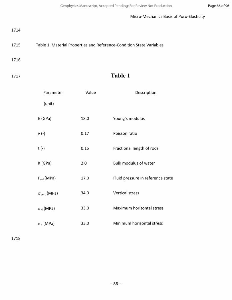
Micro-Mechanics Basis of Poro-Elasticity
– 86 –
1714
1715 Table 1. Material Properties and Reference-Condition State Variables
1716
1717 Table 1
Parameter
(unit)
Value Description
E (GPa) 18.0 Young’s modulus
v (-) 0.17 Poisson ratio
t (-) 0.15 Fractional length of rods
K (GPa) 2.0 Bulk modulus of water
Pref (MPa) 17.0 Fluid pressure in reference state
vert (MPa) 34.0 Vertical stress
H (MPa) 33.0 Maximum horizontal stress
h (MPa) 33.0 Minimum horizontal stress
1718
Page 86 of 96Geophysics Manuscript, Accepted Pending: For Review Not Production

Table 1.
Parameter
(unit)
Value Description
E (GPa) 18.0 Young’s modulus
v (-) 0.17 Poisson ratio
t (-) 0.15 Fractional length of rods
K (GPa) 2.0 Bulk modulus of water
Pref (MPa) 17.0 Fluid pressure in reference state
vert (MPa) 34.0 Vertical stress
H (MPa) 33.0 Maximum horizontal stress
h (MPa) 33.0 Minimum horizontal stress
Page 87 of 96 Geophysics Manuscript, Accepted Pending: For Review Not Production
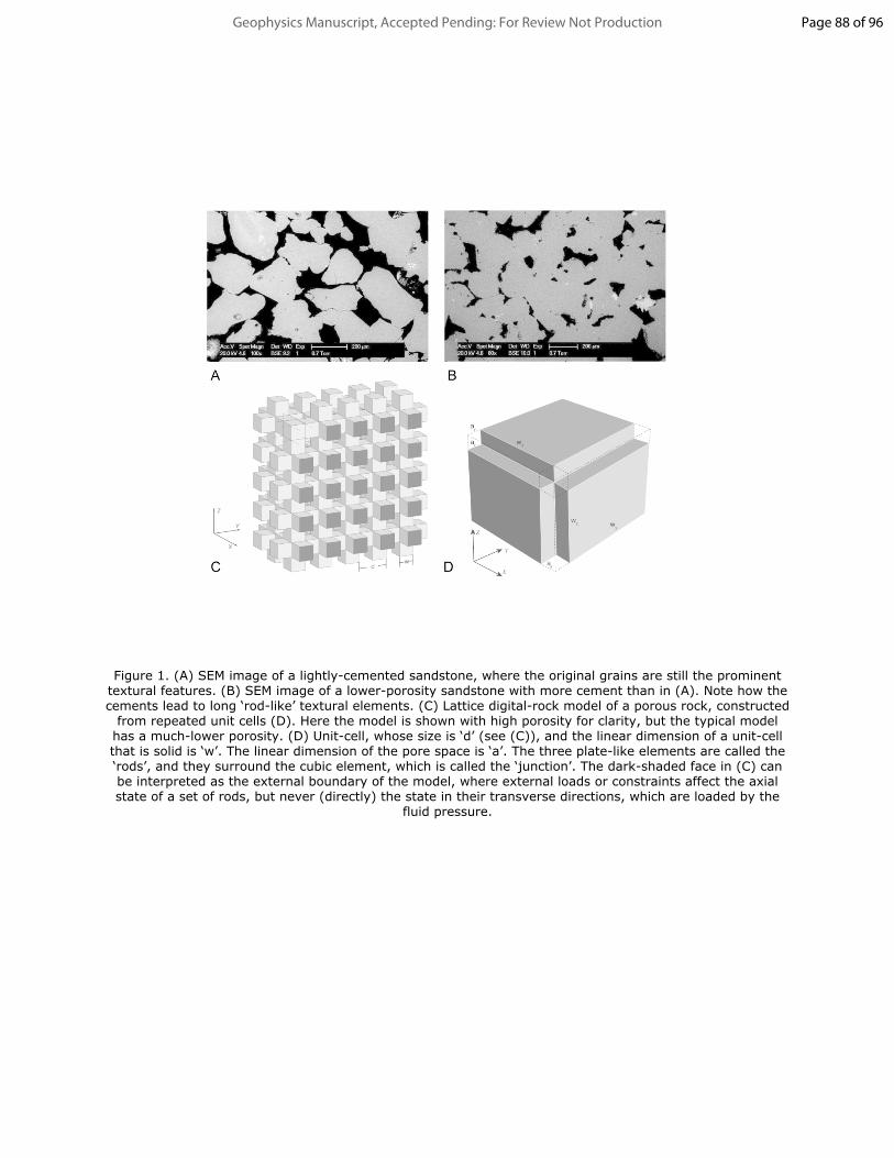
Figure 1. (A) SEM image of a lightly-cemented sandstone, where the original grains are still the prominent textural features. (B) SEM image of a lower-porosity sandstone with more cement than in (A). Note how the cements lead to long ‘rod-like’ textural elements. (C) Lattice digital-rock model of a porous rock, constructed
from repeated unit cells (D). Here the model is shown with high porosity for clarity, but the typical model has a much-lower porosity. (D) Unit-cell, whose size is ‘d’ (see (C)), and the linear dimension of a unit-cell that is solid is ‘w’. The linear dimension of the pore space is ‘a’. The three plate-like elements are called the ‘rods’, and they surround the cubic element, which is called the ‘junction’. The dark-shaded face in (C) can be interpreted as the external boundary of the model, where external loads or constraints affect the axial state of a set of rods, but never (directly) the state in their transverse directions, which are loaded by the
fluid pressure.
Page 88 of 96Geophysics Manuscript, Accepted Pending: For Review Not Production
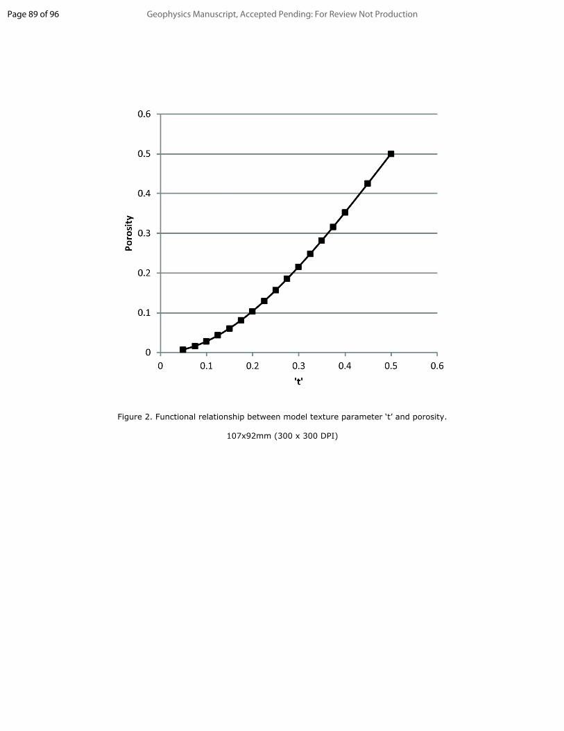
Figure 2. Functional relationship between model texture parameter ‘t’ and porosity.
107x92mm (300 x 300 DPI)
Page 89 of 96 Geophysics Manuscript, Accepted Pending: For Review Not Production

Figure 3. Illustration of a typical digital-rock model. The solid components (‘framework’) are depicted in dark grey, while the exposed pore network is shown in lighter grey.
66x66mm (300 x 300 DPI)
Page 90 of 96Geophysics Manuscript, Accepted Pending: For Review Not Production

Figure 4. Depiction of the ratio of the pore space comprised of ‘nodes’ compared to the space in ‘bonds’. Note that as ‘t’ becomes larger (> 0.4), the relative contribution from nodes is reduced, which is unlike real rocks. This change is an artefact of the strictly-geometric construction of the pore system, which in a real rock (Fig. 3) often does not show a good relationship with grain size or porosity. The lattice version of a
digital-rock is unsuited for calculating transport properties.
143x92mm (300 x 300 DPI)
Page 91 of 96 Geophysics Manuscript, Accepted Pending: For Review Not Production

Figure 5. Ratio between and P in the uni-axial loading configuration, as a function of the Poisson ratio ‘v’. The ratio of /P is plotted for several values of the textural parameter ‘t’. Note that the ratio has a
value of about 0.2 when t=0.2 (~10% porosity), and compare this with the ratio in Fig. 6.
114x69mm (300 x 300 DPI)
Page 92 of 96Geophysics Manuscript, Accepted Pending: For Review Not Production

Figure 6. Ratio between and P in the isotropic loading configuration, as a function of the Poisson ratio ‘v’. The ratio of /P is plotted for several values of the textural parameter ‘t’. Note that the ratio has a
value of about 0.8 when t=0.2 (~10% porosity), compared to the value of about 0.3 in the uni-axial case (Fig. 7).
115x69mm (300 x 300 DPI)
Page 93 of 96 Geophysics Manuscript, Accepted Pending: For Review Not Production
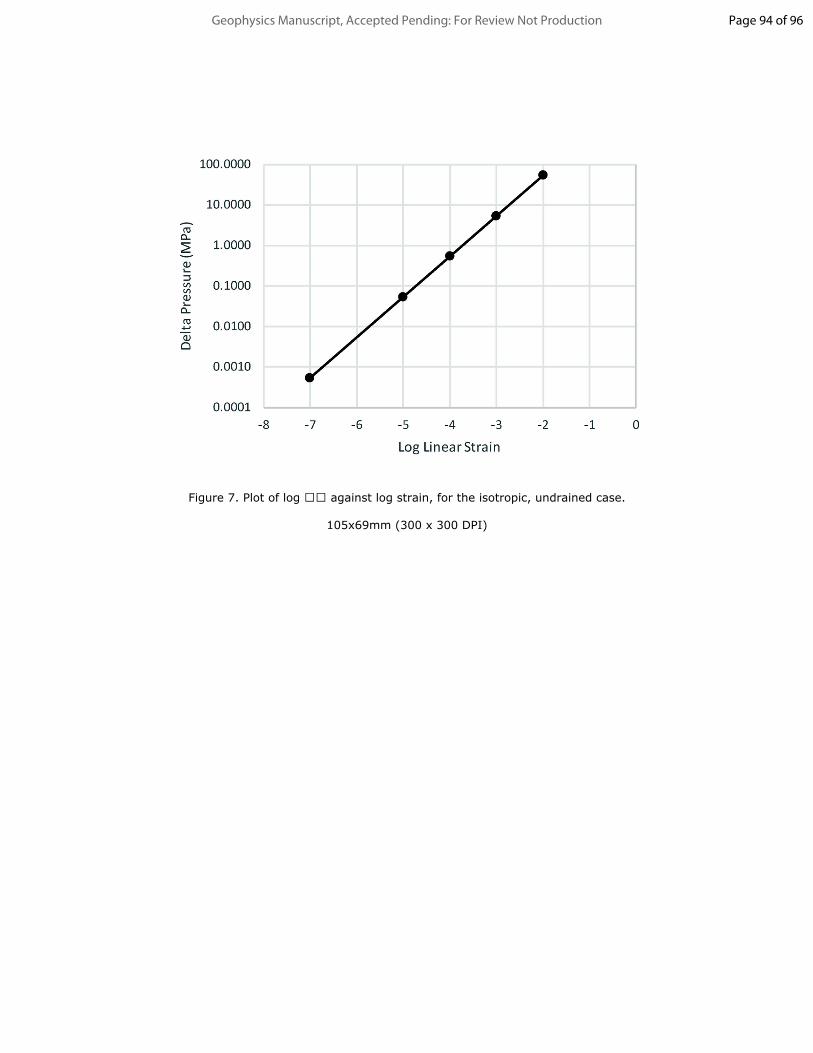
Figure 7. Plot of log against log strain, for the isotropic, undrained case.
105x69mm (300 x 300 DPI)
Page 94 of 96Geophysics Manuscript, Accepted Pending: For Review Not Production

Figure 8. Change of vertical effective stress as a function of log strain. The parameter Lambda defines the value of Pref as a function of the vertical principal stress, v. When Lambda = 0.5, this is a hydrostatic fluid
pressure, and when Lambda = 0.9, this is a highly over-pressured reference state, with low values of the effective stresses in the reference situation.
106x69mm (300 x 300 DPI)
Page 95 of 96 Geophysics Manuscript, Accepted Pending: For Review Not Production

Figure 9. Design of workflow for generating a large database of poro-elastic responses calculated from digital rock models. Section 1 describes current state-of-the-art in the use of digital rock methods that lead
to the calculation of fluid flow behaviors. Section 2 summarizes the key elements in performing the calculations of poro-elastic responses, on a digital-rock model. The analytical method used in this paper
must be transformed into suitable numerical methods that address the issues listed. Section 3 describes the translation of the large set of numerical results, arising from Section 2, into practical uses.
242x159mm (300 x 300 DPI)
Page 96 of 96Geophysics Manuscript, Accepted Pending: For Review Not Production