phone (440) 974-8888 • fax (440) 974-0165 by buyers ... · by buyers 9049 tyler blvd. • mentor,...
TRANSCRIPT
1
by Buyers
Installation/Operation
9049 Tyler Blvd. • Mentor, Ohio 44060Phone (440) 974-8888 • Fax (440) 974-0165
Toll-Free Fax 800-841-8003 • buyersproducts.com
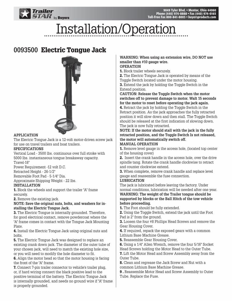
0093500 Electric Tongue Jack
APPLICATIONThe Electric Tongue Jack is a 12-volt motor-driven screw jack for use on travel trailers and boat trailers.SPECIFICATIONSVertical Load - 3500 lbs. continuous over full stroke with 5000 lbs. instantaneous tongue breakaway capacity.Travel-18"Power Requirement -12 volt D.C.Retracted Height - 26-1/2"Removable Foot Pad - 5-1/4" Dia.Approximate Shipping Weight - 22 lbs.INSTALLATION1. Block the wheels and support the trailer "A" frame securely.2. Remove the existing jack.NOTE: Save the original nuts, bolts, and washers for in-stalling the Electric Tongue Jack.3. The Electric Tongue is internally grounded. Therefore, for good electrical contact, remove powdercoat where the "A" frame comes in contact with the Tongue Jack Mounting Plate.4. Install the Electric Tongue Jack using original nuts and bolts.5. The Electric Tongue Jack was designed to replace an existing crank down jack. The diameter of the outer tube of your chosen jack, will need to match the existing hole size, or you will need to modify the hole diameter to fit.6. Align the motor head so that the motor housing is facing the front of the "A" frame.7. Connect 7-pin trailer connector to vehicle's trailer plug, or, if hard wiring connect the black positive lead to the positive terminal of the battery. The Electric Tongue Jack is internally grounded, and needs no ground wire if "A" frame is properly grounded.
WARNING: When using an extension wire, DO NOT use smaller than #10 gauge wire.OPERATION1. Block trailer wheels securely.2. The Electric Tongue Jack is operated by means of the Toggle Switch located under the motor housing.3. Extend the jack by holding the Toggle Switch in the Extend position.CAUTION: Release the Toggle Switch when the motor switches off to prevent damage to motor. Walt 15 seconds for the motor to reset before operating the jack again.4. Retract the jack by holding the Toggle Switch in the Retract position. As the jack approaches the fully retracted position it will slow down and then stall. The Toggle Switch should be released at the first indication of slowing down. The jack is now fully retracted.NOTE: If the motor should stall with the jack in the fully retracted position, and the Toggle Switch Is not released, the motor will automatically switch off.MANUAL OPERATION1. Remove level gauge in the access hole, (located top center of the housing cover)2. Insert the crank handle in the access hole, over the drive spindle tang. Rotate the crank handle clockwise to retract and counter clockwise extend.3. When complete, remove crank handle and replace level gauge and reassemble the fuse connection.LUBRICATIONThe jack is lubricated before leaving the factory. Under normal conditions, lubrication will be needed after one year.WARNING: The weight of the Trailer tongue should be supported by blocks or the Ball Hitch of the tow vehicle before proceeding.1. The Foot should be fully extended.2. Using the Toggle Switch, extend the jack until the Foot Pad is 2" from the ground.3. Loosen the four #8 Phillips Head Screws and remove the Gear Housing Cover.4. If required, repack the exposed gears with a common Lithium Base Machine Grease.5. Reassemble Gear Housing Cover.6. Using a 1/4" Allen Wrench, remove the four 5/16" Socket Head Screws holding the Motor Head to the Outer Tube.7. Lift the Motor Head and Screw Assembly away from the Outer Tube.8. Clean and regrease the Jack Screw and Nut with a common Lithium Base Machine Grease.9 . Reassemble Motor Head and Screw Assembly to Outer Tube. Replace the Fuse.
2
by Buyers
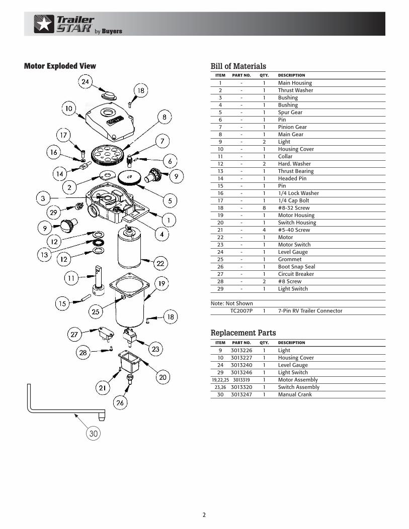
Bill of Materials
1 - 1 Main Housing 2 - 1 Thrust Washer 3 - 1 Bushing 4 - 1 Bushing 5 - 1 Spur Gear 6 - 1 Pin 7 - 1 Pinion Gear 8 - 1 Main Gear 9 - 2 Light 10 - 1 Housing Cover 11 - 1 Collar 12 - 2 Hard. Washer 13 - 1 Thrust Bearing 14 - 1 Headed Pin 15 - 1 Pin 16 - 1 1/4 Lock Washer 17 - 1 1/4 Cap Bolt 18 - 8 #8-32 Screw 19 - 1 Motor Housing 20 - 1 Switch Housing 21 - 4 #5-40 Screw 22 - 1 Motor 23 - 1 Motor Switch 24 - 1 Level Gauge 25 - 1 Grommet 26 - 1 Boot Snap Seal 27 - 1 Circuit Breaker 28 - 2 #8 Screw 29 - 1 Light Switch
Note: Not Shown TC2007P 1 7-Pin RV Trailer Connector
ITEM PARTNO. QTY. DESCRIPTION
Motor Exploded View
Replacement Parts
9 3013226 1 Light 10 3013227 1 Housing Cover 24 3013240 1 Level Gauge 29 3013246 1 Light Switch 19,22,25 3013319 1 Motor Assembly 23,26 3013320 1 Switch Assembly 30 3013247 1 Manual Crank
ITEM PARTNO. QTY. DESCRIPTION
30
3
by Buyers
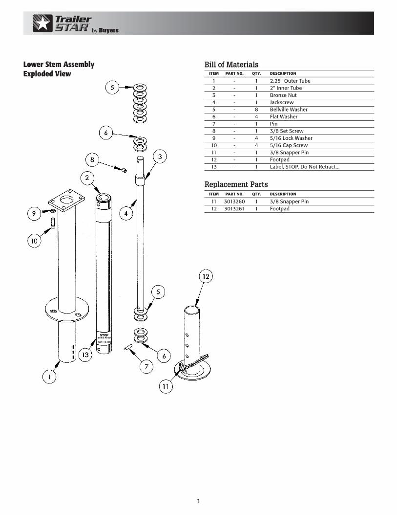
Lower Stem AssemblyExploded View
Bill of Materials
1 - 1 2.25" Outer Tube 2 - 1 2" Inner Tube 3 - 1 Bronze Nut 4 - 1 Jackscrew 5 - 8 Bellville Washer 6 - 4 Flat Washer 7 - 1 Pin 8 - 1 3/8 Set Screw 9 - 4 5/16 Lock Washer 10 - 4 5/16 Cap Screw 11 - 1 3/8 Snapper Pin 12 - 1 Footpad 13 - 1 Label, STOP, Do Not Retract...
ITEM PARTNO. QTY. DESCRIPTION
Replacement Parts
11 3013260 1 3/8 Snapper Pin 12 3013261 1 Footpad
ITEM PARTNO. QTY. DESCRIPTION
4
by Buyers
9049 Tyler Blvd. • Mentor, Ohio 44060Phone (440) 974-8888 • Fax (440) 974-0165
Toll-Free Fax 800-841-8003 • buyersproducts.com
WARRANTYBuyers Products Co. warrants all truck/trailer hardware manufactured or distributed by it, to be free from defects in material and workmanship for a period of one year from date of shipment. Parts must be properly installed and used under normal conditions. Any product which has been altered, including modification, misuse, accident or lack of maintenance will not be considered under warranty. Normal wear is excluded. The sole responsibility of Buyers Products Co. under this warranty is limited to repairing or replacing any part or parts which are returned, prepaid, and are found to be defective by Buyers Products Co. Authorization from Buyers Products Co. must be obtained before returning any part. No charges for transportation or labor performed on Buyers’ products will be allowed under this warranty.
3013269 Rev. E
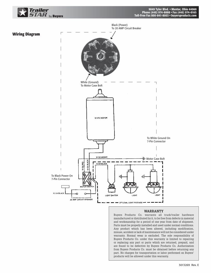
Wiring Diagram
White (Ground) To Motor Case Bolt
Black (Power) To 20 AMP Circuit Breaker
To Black Power On 7-Pin Connector
To White Ground On 7-Pin Connector
Motor Case Bolt