phone: (601) 656-5866 philadelphia, ms 39350 fax: (601 ... manual.pdf · installation and operating...
TRANSCRIPT

INSTALLATION AND
OPERATING INSTRUCTIONS
FOR
THE HARDYOUTSIDE WOOD
BURNING HEATER
Model – KBP270Model – KBP270
HARDY MANUFACTURING
COMPANY, INC.
12345 ROAD 505
PHILADELPHIA, MS 39350
PHONE: (601) 656-5866
FAX: (601) 656-4559
www.hardyheater.com
HARDY MANUFACTURING
COMPANY, INC.
12345 ROAD 505
PHILADELPHIA, MS 39350
PHONE: (601) 656-5866
FAX: (601) 656-4559
www.hardyheater.comRev. 2/22/2014

THIS PAGE INTENTIONALLY LEFT BLANK

(MODEL KBP270) i
INTRODUCTION Thank you for purchasing our Hardy Outside Wood Pellet Burning Heater. It represents the result of many years of Hardy experience and the input of Hardy customers in the production of a top quality heater. With the purchase of this Hardy Heater, you can now appreciate the high degree of craftsmanship and reliability that have made The Hardy the leader in the Outside Pellet burning Heater field. This manual will provide you with a good basic understanding of the installation and operation of this heater.
THIS MANUAL INCLUDES IMPORTANT SAFETY INFORMATION.
Your new heater should have the following:
(1) Owner’s manual complete with installation and hook-up instructions (2) Warranty & return warranty card (3) A tube of silicone (located in the firebox for shipping) (4) 2 double wall sections of Smoke stack with a trim ring and cap (5) Condenser stack with trim ring (6) Ash removal tool (7) Metal ash removal pan (8) Feed auger assembly
Should your heater not have any of these items or if you have any questions regarding the operation or maintenance of your heater, please consult you local Hardy dealer. Again, thank you for purchasing a Hardy Heater.
Sincerely, Frank L. Moore
President Hardy Manufacturing Co., Inc.
(MODEL KBP270) ii
Please fill in the following information
Hardy Model
Serial Number
Date of Purchase
Date of Installation
Dealer Purchased from
Dealer Address
Dealer Phone Number
HARDY MANUFACTURING COMPANY, INC. 12345 ROAD 505
PHILADELPHIA, MS 39350 PHONE: (601) 656-5866 www.hardyheater.com
Please keep this manual with all other important papers. The information in this manual is necessary for the installation, operation and proper use of this unit. If you should ever have a problem or question please refer to this manual or have it available when you call your Hardy Dealer or Hardy Manufacturing Company, Inc.
(MODEL KBP270) iii
SAFETY PRECAUTIONS WARNING
Do not operate this equipment for other than its intended purpose nor other than in accordance with the instructions contained in this manual and all other instructions accompanying the unit. For units covered by this instruction book, it is important to observe safety precautions to protect yourself from possible injury. Among the many considerations, you are advised to:
Observe all safety stickers on the unit.
This unit must be wired by a qualified electrician in accordance with the National Electrical Code.
Never use any type of petroleum based product, charcoal starter, lighter fluid, or any other flammable accelerant to start your unit.
Fuel: wood pellets.
Never leave the door open, always latch the door securely.
Always use proper care when installing, operating and maintaining the unit.
Do not modify the unit.
Do not substitute repairs which can be provided by your dealer, distributor, or Hardy Manufacturing Co. Inc.
Failure to heed this warning or any additional warnings on the unit may result in an accident causing personal injury and loss of warranty.

(MODEL KBP270) iv
THE HARDY OUTSIDE PELLET BURNING HEATER
How does an outside heater heat my home?
The Hardy outside pellet burning heater is designed to save the most energy and provide the most comfortable heating available. It heats your home by heating a stainless steel tank filled with water, which surrounds the firebox of the outside heater. The heater is a non pressurized boiler with an atmospheric vent. This hot water is then circulated through underground hot water pipes to a water coil inside your existing central duct system. The Hardy Heater can be connected to any existing hydronic heating system that operates at 170 degrees Fahrenheit or less. How does THE HARDY heat water for household use?
A plate heat exchanger (optional) is installed in the hot water circulator line. When you open a hot water faucet inside your home, the cold water passes through the other side of the heat exchanger and the water going to your hot water heater is preheated. The only additional energy required is maintaining the hot water temperature. The plate heat exchangers can be used for pools, dairies and other domestic hot water needs. How do the Thermostat Controls work?
The only visible addition to the heating system inside your home is the thermostat which is located next to your existing thermostat. The two thermostats are installed so that if the outside pellet burning heater is not in operation, your existing unit can be used to maintain your household temperature. The wall thermostat which regulates the heat from the outside heater turns the blower on inside your central unit to force air across the hot coil. This forces hot air into your central duct system. The outside heater has a Process Control Module which senses the water temperature of the unit. This module cycles the heater on and off in order to maintain a preset water temperature. Where should an Outside Pellet Burning Heater be located?
The outside unit should be located at least 10 feet from your home so that all fire danger is removed from your home. The unit may be installed as much as 100 feet away and still heat your house and hot water. If the unit is located more than 100 feet away, you may experience some heat loss on the water supplying your water heater. Locate the outside pellet burning heater where it will be convenient for refueling. All water and power lines are installed underground between the house and the outside wood heater.
(MODEL KBP270) v
TABLE OF CONTENTS
SECTION I: General Information 1-1 Specifications ............................................................... 1 1-2 Heater Component Parts .......................................... 2-6
SECTION II: Installation of Heater 2-1 Location of Heater ........................................................ 7 2-2 Location of Plumbing & Electrical Lines ....................... 8 2-3 Connection of Power to Heater .................................... 9 2-4 Wiring Diagram ............................................................ 9 2-5 Plumbing Connections ............................................... 10 2-6 Installation of Smoke Stacks and Condenser Stack 11 2-7 Filling the Heater with Water……………………………12 2-8 Priming the Pump ...................................................... 13 SECTION III: Connection to Central Heating/AC System 3-1 Connection to Central Unit with existing Blower Relay .................................... 14-15 3-2 Location of Heating Coil ....................................... 16-17 SECTION IV: Connection to Hydronic Heating Systems (Baseboard) 4-1 Connection to Hydronic System ................................. 18 SECTION V: Plumbing Options for Domestic Water 5-1 Plate Heat Exchanger for Domestic Water ................ 19 SECTION VI: Heater Operation 6-1 Firing the Heater ........................................................ 20 6-2 Burn Mode ................................................................. 21 6-3 Shut Down Mode ....................................................... 22

(MODEL KBP270) vi
TABLE OF CONTENTS continued
SECTION VII: Service Information 7-1 Water Temperature .................................................... 23 7-2 Fuel Usage ................................................................ 23 7-3 Moisture in Firebox .................................................... 23 7-4 Improper Burning ....................................................... 23 7-5 Ash Removal ............................................................. 23 7-6 Water Circulation System .......................................... 24 7-7 Combustion Air Blower Assembly…………………… . 24 7-8 Low Water Sensor ..................................................... 24 7-9 Process Control Module ............................................. 24 7-10 Feed Auger Assembly .............................................. 25 7-11 Stir Shaft Motor Assembly ....................................... 25 7-12 Stir Shaft Assembly.................................................. 25 SECTION VIII: Heater Maintenance 8-1 Daily Maintenance ..................................................... 26 8-2 Weekly Maintenance.................................................. 27 8-3 Extended Period Shut Down and Start Up ................ 28 SECTION IX: Appendix 9-1 Modes of Operation Flow Diagram ............................ 29 9-2 General Trouble Shooting Guide .............................. 30 9-3 Module Specific Trouble Shooting Guide .................. 31 9-4 Maintenance Instructions ...................................... 32-40

HARDY MANUFACTURING CO., INC (MODEL KBP270) PAGE 1
SECTION I
GENERAL INFORMATION
1 – 1 Specifications
Type of fuel – Wood pellets For outdoor use only Electrical Rating 115 VAC/ 60 HZ / 1PH MFS-20 AMP, MCA-20 AMP Clearance to Combustibles Top, Rear, Sides 18” Chimney Connector 18” Front 48” Flooring Non Combustible Water Capacity KBP270 – Holds Approximately 40 Gallons of Water
Heater Dimensions Description Width Depth Height Weight KBP270 31” 75” 48” 636 lbs.
HARDY MANUFACTURING CO., INC (MODEL KBP270) PAGE 2
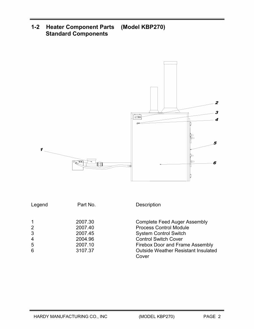
1-2 Heater Component Parts (Model KBP270) Standard Components
Legend Part No. Description 1 2007.30 Complete Feed Auger Assembly 2 2007.40 Process Control Module 3 2007.45 System Control Switch 4 2004.96 Control Switch Cover 5 2007.10 Firebox Door and Frame Assembly 6 3107.37 Outside Weather Resistant Insulated
Cover
Fo
Water
2
3
4
5
6
1

HARDY MANUFACTURING CO., INC (MODEL KBP270) PAGE 3
1-2 Heater Component Parts (Model KBP270) continued
Legend Part No. Description 7 3100.58 Tank Assembly 8 607.42 3/4” Boiler Drain Valve 9 2007.19 Combustion Blower Assembly 10 502.00 Taco 009 Bronze Circulator 11 607.12 3/4” Brass Ball Valve 12 1100.28 Low Water Switch 13 1100.27 Automatic Water Fill Solenoid 14 2006.21 Stir Motor Assembly 15 2000.53 Process Control Relay 16 2000.55 Process Control Relay Socket 17 810.30 3/4” x 11.75” Raupex Pex A Pipe 18 810.32 3/4” x 2.5” Raupex Pex A Pipe 19 2007.13 Air/Power Transmission Assy 20 2004.00 GFCI
7
9
10
11
11
12 13
14
15
16
17
18 19
20
8

HARDY MANUFACTURING CO., INC (MODEL KBP270) PAGE 4
1-2 Heater Component Parts (Model KBP270) continued
Standard Components
Legend Part No. Description 21 2007.11 Firebox Burn Chamber Assembly 22 2007.24 Stir Rod/Combustion Air Distribution Assy 23 2007.20 Front Bearing assembly 24 2007.70 Front Bearing Hi-Temp Assy 25 2007.12 Heat/Particulate Recovery Module. 26 2007.50 Firebrick Assy. 27 608.36 1” Brass Union Fitting.
25
21
24
23
22
26
27
HARDY MANUFACTURING CO., INC (MODEL KBP270) PAGE 5
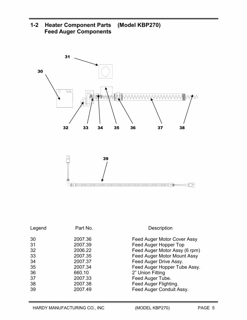
Legend Part No. Description 30 2007.36 Feed Auger Motor Cover Assy 31 2007.39 Feed Auger Hopper Top 32 2006.22 Feed Auger Motor Assy (6 rpm) 33 2007.35 Feed Auger Motor Mount Assy 34 2007.37 Feed Auger Drive Assy. 35 2007.34 Feed Auger Hopper Tube Assy. 36 660.10 2” Union Fitting 37 2007.33 Feed Auger Tube. 38 2007.38 Feed Auger Flighting. 39 2007.49 Feed Auger Conduit Assy.
1-2 Heater Component Parts (Model KBP270) Feed Auger Components
30
31
32 33 34 35 36 37 38
39
HARDY MANUFACTURING CO., INC (MODEL KBP270) PAGE 6
Fo
Water
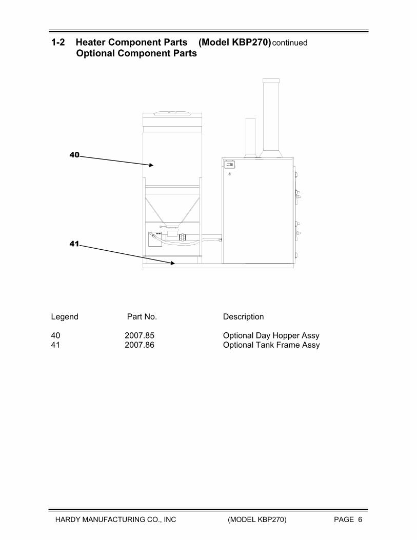
1-2 Heater Component Parts (Model KBP270) continued
Optional Component Parts
Legend Part No. Description 40 2007.85 Optional Day Hopper Assy 41 2007.86 Optional Tank Frame Assy
40
41
HARDY MANUFACTURING CO., INC (MODEL KBP270) PAGE 7
SECTION II
INSTALLATION OF HEATER
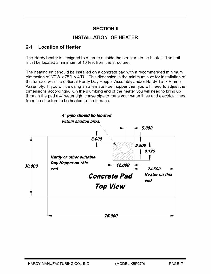
2-1 Location of Heater The Hardy heater is designed to operate outside the structure to be heated. The unit must be located a minimum of 10 feet from the structure. The heating unit should be installed on a concrete pad with a recommended minimum dimension of 30”W x 75”L x 4”D . This dimension is the minimum size for installation of the furnace with the optional Hardy Day Hopper Assembly and/or Hardy Tank Frame Assembly. If you will be using an alternate Fuel hopper then you will need to adjust the dimensions accordingly. On the plumbing end of the heater you will need to bring up through the pad a 4” water tight chase pipe to route your water lines and electrical lines from the structure to be heated to the furnace.
75.000
30.000 12.000
3.500
5.000
9.125
Concrete Pad
Top View
Day Hopper on this
end
Heater on this
end
4" pipe should be located
within shaded area.
3.000
24.500
Hardy or other suitable
HARDY MANUFACTURING CO., INC (MODEL KBP270) PAGE 8
2-2 Location of Plumbing and Electrical Lines
To locate the connection points for plumbing and electrical lines you will need to remove the rear access panel of the heater. The plumbing and electrical lines for your unit must be installed underground in a water tight pipe or other suitable insulation means. The water lines must be buried below the frost line to prevent freezing. Verify the correct depth according to local building codes prior to installation. The installation will require a trench wide enough to accommodate a 4” watertight pipe or other insulation means. All plumbing and electrical lines should be installed inside the 4” water tight pipe or other insulation means for a standard installation. An additional pipe may be required if more than 1 zone or location is to be heated. If more than one location is to be heated, a second 4” or single 6” watertight pipe or other insulation means will need to be installed underground for the water lines and thermostat wires of the second location. This pipe will run from the rear of the unit to the location to be heated. Contained Inside the 4” watertight pipe is a minimum of two water lines and electrical supply wire. The listing below describes each line and related function. 1. One water supply line to heating system 2. One water return line from heating system
(Note: The supply and return lines must be at least 3/4” pipe. 1” pipe may be required for longer distances. Some hydronic applications also require 1” pipe.)
3. One #12/2 W/Gnd NM type UF underground wire
HARDY MANUFACTURING CO., INC (MODEL KBP270) PAGE 9
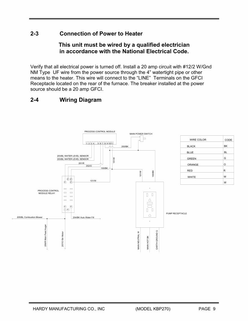
2-3 Connection of Power to Heater
This unit must be wired by a qualified electrician in accordance with the National Electrical Code.
Verify that all electrical power is turned off. Install a 20 amp circuit with #12/2 W/Gnd NM Type UF wire from the power source through the 4” watertight pipe or other means to the heater. This wire will connect to the “LINE” Terminals on the GFCI Receptacle located on the rear of the furnace. The breaker installed at the power source should be a 20 amp GFCI.
2-4 Wiring Diagram
1110987654321
415
12
8
9
14
13
MA
IN H
OT
BK
MA
IN N
EU
TR
AL W
EA
RT
H G
RO
UN
D G
10
0/B
K
10
1/W
10
1/W
101/W
100/BK
200/BK
201/R
202/O
203/BL WATER LEVEL SENSOR
204/BK Auto Water Fill205/BL Combustion Blower
20
6/R
Ma
in F
ee
d A
ug
er
20
7/O
Stir
Mo
tor
WHITE
RED
ORANGE
GREEN
BLUE
BLACK BK
BL
G
O
R
W
W
WIRE COLOR CODE
PROCESS CONTROL MODULEMAIN POWER SWITCH
PUMP RECEPTACLE
PROCESS CONTROL
MODULE RELAY
203/BL WATER LEVEL SENSOR

HARDY MANUFACTURING CO., INC (MODEL KBP270) PAGE 10
2-5 Plumbing Connections
Connection to Heating System 1. The pipe that will supply the heating system is connected on the lower side of the
pump, ( Item 1). 2. The pipe that will carry the return water from the heating system is connected to the
3/4” Tee fitting as shown in diagram below. ( Item 2 ).
Water pipes must be designed for hot water service (ex. copper, cpvc, or Pex A). Pipes should be installed in a 4” watertight pipe or
some other type of insulating means to prevent heat loss from heater to heating system. Use only copper, brass, or stainless steel fittings.
Do not use galvanized or black iron.
2
Supply to
Heating
System
Heating
System
Return
1
HARDY MANUFACTURING CO., INC (MODEL KBP270) PAGE 11
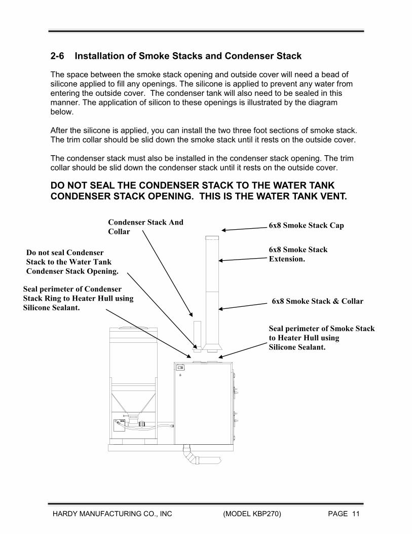
2-6 Installation of Smoke Stacks and Condenser Stack
The space between the smoke stack opening and outside cover will need a bead of silicone applied to fill any openings. The silicone is applied to prevent any water from entering the outside cover. The condenser tank will also need to be sealed in this manner. The application of silicon to these openings is illustrated by the diagram below. After the silicone is applied, you can install the two three foot sections of smoke stack. The trim collar should be slid down the smoke stack until it rests on the outside cover. The condenser stack must also be installed in the condenser stack opening. The trim collar should be slid down the condenser stack until it rests on the outside cover.
DO NOT SEAL THE CONDENSER STACK TO THE WATER TANK CONDENSER STACK OPENING. THIS IS THE WATER TANK VENT.
F
Water
Condenser Stack And
Collar
Do not seal Condenser
Stack to the Water Tank
Condenser Stack Opening.
Seal perimeter of Condenser
Stack Ring to Heater Hull using
Silicone Sealant.
6x8 Smoke Stack Cap
6x8 Smoke Stack
Extension.
6x8 Smoke Stack & Collar
Seal perimeter of Smoke Stack
to Heater Hull using
Silicone Sealant.

HARDY MANUFACTURING CO., INC (MODEL KBP270) PAGE 12
2-7 Filling the Heater with Water
THE FURNACE MUST BE FILLED WITH WATER BEFORE OPERATION. There is a low water switch located in a fitting on the rear of the heater. This low water switch signals a low water condition in the process control module. The process control module will enable the automatic water fill valve assembly until the condition no longer exists. The Furnace will not operate while in a Low Water Condition. There are certain parts of the country that have high enough levels of chloride in the water to be harmful to stainless steel tanks. Even though the USDA allows up to 250 parts per million of chloride (salt) in the water as acceptable for drinking, experience has shown that chloride levels as low as 45 parts per million will eventually cause stress corrosion cracking in stainless steel tanks when water is heated. It is therefore required to use rain water or bottled water with chloride content of less than 15 parts per million or test the water supply for chloride to assure that the water supply does not exceed 45 parts per million. Call your Hardy dealer to obtain a chloride test on your water supply. If the chloride content of your local water supply exceeds the specifications mentioned above and necessitates the use of bottled or rain water, please do so to maintain the warranty of your heater. Fill your heater with water through the condenser stack opening until the water level is approximately 1” from top of tank.

HARDY MANUFACTURING CO., INC (MODEL KBP270) PAGE 13
2-8 Priming the Pumps
Once the furnace has been filled with water you will need to prime the pumps. You will need to open the pump valve (Item 1) and the return valve (Item 2 ).
1
2
Pump
Valve
Return
Valve

HARDY MANUFACTURING CO., INC (MODEL KBP270) PAGE 14
SECTION III
CONNECTION TO CENTRAL HEATING/AC SYSTEM
3-1 Connection to Central Unit with Existing Blower Relay
This unit must be wired by a qualified electrician in accordance with the National Electrical Code.
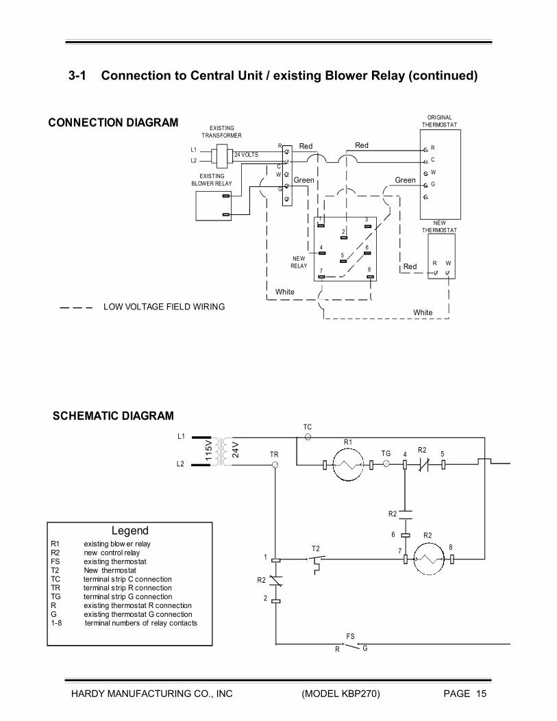
Turn off all power going to your central Air Handler System. You will need to add a double pole / double throw relay to your central air handler. You will also need a heat only thermostat added to the wall, preferably next to the existing thermostat. Run a two (2) conductor thermostat wire from the air handler to the new heat only thermostat that was added to the wall. The normal colors for this wire are Red & White. NOTE: If you are not familiar with the control circuit of your central unit, do not continue beyond this point. Call a heating and air conditioning serviceman to complete the wiring. Improper wiring can cause excessive electrical usage or cause your blower motor to over heat and burn out. At the wall heat only thermostat connect the red wire to the screw terminal marked R and the white wire to the screw terminal marked W. At the Central air handler where you added the relay, connect the white wire that is going to the new heat only wall thermostat to terminal #7 of the new relay along with a short jumper wire that will connect to terminal #6 of the new relay. Next find the red wire going from the air handler control wiring to the original wall thermostat. Cut this wire and connect the end that is going to the wall thermostat to terminal # 2 on the new relay. The end of the red wire that is still connected to the control wiring of the air handler will need to be connected to terminal # 1 along with the new red wire that is going to the new heat only wall thermostat. Locate the Green wire going from the Central air handler control wiring to the original wall thermostat. Cut this wire. Connect the end of the green wire that is going to the original wall thermostat to terminal #5 of the new relay. Connect the end of the green wire that is still connected to the central air handler control wiring to terminal #4. Locate the low voltage transformer that is providing you with 24 volt power. Find the common lead of this transformer and connect a wire to this lead and to terminal #8 of the new relay.
HARDY MANUFACTURING CO., INC (MODEL KBP270) PAGE 15
3-1 Connection to Central Unit / existing Blower Relay (continued)
1
2
3
4
5
6
7 8
R
C
G
W
L1
L224 VOLTS
R
C
G
W
EXISTING
TRANSFORMER
ORIGINAL
THERMOSTAT
EXISTING
BLOWER RELAY
NEW
RELAY
NEW
THERMOSTAT
L1
L2
11
5V
24
V
TR
TC
R1
R2
T2
FS
1
2
4 5
6
78
R2
R2
R2
TG
CONNECTION DIAGRAM
SCHEMATIC DIAGRAM
GR
LOW VOLTAGE FIELD WIRINGWhite
Red
White
Red
Green Green
Red
LegendR1 existing blow er relayR2 new control relayFS existing thermostatT2 New thermostatTC terminal s trip C connectionTR terminal s trip R connectionTG terminal strip G connectionR existing thermostat R connectionG existing thermostat G connection1-8 terminal numbers of relay contacts
R W

HARDY MANUFACTURING CO., INC (MODEL KBP270) PAGE 16
3-2 Location of Heating Coil
The following diagrams and pictures on this page and the following page show various methods of installing
the heating coil in forced air system.
Supply Air
Return Air
Install and Insulate Heating Coil
in supply side of system
and in a protected environment
Package System
Supply Air

HARDY MANUFACTURING CO., INC (MODEL KBP270) PAGE 17
3-2 Location of Heating Coil (continued)
Air Flow
Air Flow
Air Must be
Filtered before
passing through
Heating Coil.
Vertical
Flow
System
Air FlowAir Flow
Air Must be
Filtered before
passing through
Heating Coil.
Horizontal Flow System

HARDY MANUFACTURING CO., INC (MODEL KBP270) PAGE 18
SECTION IV
CONNECTION TO HYDRONIC HEATING SYSTEMS (BASEBOARD)
4-1 Connection to Hydronic System
This unit must be wired by a qualified electrician in accordance with the National Electrical Code.
The preferred method for connecting the Hardy Outside Pellet Burning Heater to an existing Hydronic system is by installing a p/n 300.01 40 plate heat exchanger w/ 1” fittings into the return line of the existing boiler system. Run 2 -1” potable hot water lines from the wood furnace to the existing boiler system. Connect these lines to the plate heat exchanger so that the water flow of the furnace is opposite of that from the boiler system.
Existing
Boiler
Heat
Zone
Heat
Zone
Existing
Pump
Heat Exchanger
Boiler Supply
HARDY MANUFACTURING CO., INC (MODEL KBP270) PAGE 19
Cold Water Supply
Water
Heater
Hot Outlet
Cold Inlet
! DANGER
Water Temperature
over 125 degrees
can cause severe
burns instantlyHeater with Hull and stacks
removed to show connections.
P/N H300.02
20 Plate
Heat Exchanger
w/ 3/4" fittings
Furnace
Out
Domestic
In
Close this
valve
Furnace
In
Domestic
Out
SECTION V
PLUMBING OPTIONS FOR DOMESTIC WATER
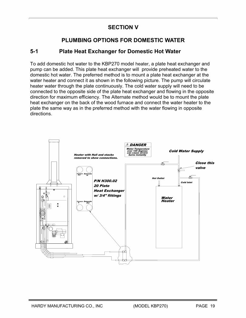
5-1 Plate Heat Exchanger for Domestic Hot Water To add domestic hot water to the KBP270 model heater, a plate heat exchanger and pump can be added. This plate heat exchanger will provide preheated water to the domestic hot water. The preferred method is to mount a plate heat exchanger at the water heater and connect it as shown in the following picture. The pump will circulate heater water through the plate continuously. The cold water supply will need to be connected to the opposite side of the plate heat exchanger and flowing in the opposite direction for maximum efficiency. The Alternate method would be to mount the plate heat exchanger on the back of the wood furnace and connect the water heater to the plate the same way as in the preferred method with the water flowing in opposite directions.
HARDY MANUFACTURING CO., INC (MODEL KBP270) PAGE 20
SECTION VI
HEATER OPERATION
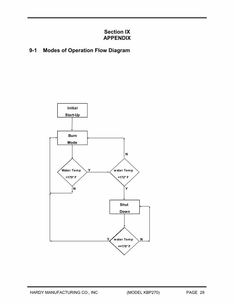
6-1 Firing the Heater Hardy Manufacturing Company Inc.’s recommended fuel for this heater is Wood pellets. Proper storage of wood pellets is important for the proper operation of a pelletized Biofuel Burning Hydronic Heater. Fuel must be stored in a clean, dry environment and should be protected from contact with moisture, like rain, condensation, etc. Normal humidity will not harm the pellets. This heater has two basic modes of operation: Burn Mode Shut Down Mode Each Mode of operation is determined by the Process Control Module. The Process Control Module constantly monitors the systems to switch between the different modes of operation as required.

HARDY MANUFACTURING CO., INC (MODEL KBP270) PAGE 21
6-2 Burn Mode This mode of operation is during initial startup of heater and during normal operation of the heater. Verify the water level of the heater is at operating levels prior to start of lighting process. The heater is supplied with an automatic water fill feature. This feature is activated by a low water switch located in the upper rear of the furnace. After the initial fill of the water tank and application of electrical power to the heater this feature will keep the water levels at a safe operating level. The Furnace will not operate if a low water condition exists. Fill the fuel storage bin with the recommended type of fuel. Fuels not suited for the heater type will result in poor and erratic performance and could possibly damage the heater. Open shut off gate located in the hopper distribution tube by sliding the T-handle out. Some maintenance procedures will require the gate to be closed to shut off the supply of fuel. Activate the system control switch located just below the process control module. At this point the Feed Auger should be engaged and in operation. The Combustion blower and Stir shaft drive motor should be operating as well. Allow the feed auger to operate for a few minutes until there are approx. 4 to 5 cups of pellets in the Firebox Burn chamber. Light the pellets using a safe suitable method. Do not use any type of petroleum based products, charcoal starter, lighter fluid, or any other flammable accelerant to start your unit.

HARDY MANUFACTURING CO., INC (MODEL KBP270) PAGE 22
6-3 Shut Down Mode When tank water temperature reaches 172º F the heater will enter into the Shut Down Mode of operation. In this mode the Feed Auger, Combustion Air Blower Assy and the Stir Rod/Combustion Air Distribution Assy will be off. To prevent overheating the pump will run continuously. The heater will remain in this mode of operation until the tank water temperature reaches 170º F. At this point the heater will enter into the Burn Mode of operation and all systems will be active.
Fo
Water
Process Control Module
System Control Switch
Shut Off Gate
6-2 Burn Mode continued
HARDY MANUFACTURING CO., INC (MODEL KBP270) PAGE 23
SECTION VII
SERVICE INFORMATION
7-1 Water Temperature The tank water temperature is maintained by the Process Control Module. The normal operating temperature of 170° F to 172° F is preset at the factory and should not be adjusted.
7-2 Fuel Usage Hardy Manufacturing recommends the use of wood pellets. Any fuels other than those specified will result in poor and erratic heater performance. This heater is designed to use a minimum amount of fuel but as with any heater of this type fuel usage is based upon the required load and temperature requirements. Refer to the troubleshooting section located in the appendix for problems associated with excessive fuel usage or poor heater performance.
7-3 Moisture in the Firebox During startup of a new heater or the first time you operate an existing heater each year, you will probably notice moisture in the firebox. This is normal and should not cause alarm. If after a few days of operation a high moisture content is still evident the heater should be shut down and checked for leaks.
7-4 Improper Burning Improper burning during the normal operation of the heater is normally caused by lack of combustion air or fuel in the firebox chamber. First, verify the Feed Auger Assembly is engaged and operating. Open the Firebox Door and carefully view the fuel inlet located in the rear right hand section of the Firebox Burn Chamber. Verify that raw fuel is present. If no fuel is present, there is possibly a blockage in the Auger system that needs to be corrected. Second, if the Auger System is operating properly the heater should be shutdown and cleaned according to section VIII Heater Maintenance. Remove the Stir Shaft Assembly according to section 9-4 Maintenance Instructions, and check for clogged orifices in the Stir Shaft Fingers.
7-5 Ash Removal Ashes must be removed from inside the heater on a routine basis. Excessive ash buildup inside the Firebox and recovery chambers will reduce heating efficiency and can lead to premature breakdown of some of the internal components. Refer to section 9-4 Maintenance Instructions for ash removal.
HARDY MANUFACTURING CO., INC (MODEL KBP270) PAGE 24
7-6 Water Circulation System The water circulation system circulates heated water from the heater to the structure to be heated. (See pump maintenance in section 9-4).
7-7 Combustion Air Blower Assy The combustion blower forces air into the fire chamber when the furnace is in the burn mode.
7-8 Low Water Sensor The low water switch signals a low water condition in the Process Control Module. The Process Control Module will activate the automatic water fill valve assembly until the low water condition no longer exists. The heater will not operate if a low water condition exists.
7-9 Process Control Module Each mode of operation is determined by the Process Control Module. The Module constantly monitors the systems to switch between the different modes of operation as required.

HARDY MANUFACTURING CO., INC (MODEL KBP270) PAGE 25
7-10 Feed Auger Assembly The Feed Auger Assembly distributes raw fuel from the Fuel storage bin directly into the Firebox. The Feed auger operates on a cycle as determined by the Process Control Panel to distribute the correct amount of fuel for the heater to operate properly.
7-11 Stir Shaft Motor Assembly The Stir Shaft Motor Assembly serves as a power transmission to the Firebox Stir Shaft Assembly. The Stir Motor operates on a cycle as determined by the Process Control Panel.
7-12 Stir Shaft Assembly The Stir Shaft Assembly distributes fuel evenly throughout the firebox and also through its orifices provides the necessary combustion air for the fuel to burn properly.

HARDY MANUFACTURING CO., INC (MODEL KBP270) PAGE 26
SECTION VIII
HEATER MAINTENANCE
The Hardy Heater is designed for ease of operation and ease of service. There is a minimal amount of maintenance that has to be done for proper operation of your new unit.
8-1 Daily Maintenance 1. Make sure you have adequate fuel in the hopper. 2. Open the front door and check for any accumulation of ash. If ash has started to
accumulate remove it according to instructions for ash removal in the weekly maintenance section 8-2.

HARDY MANUFACTURING CO., INC (MODEL KBP270) PAGE 27
8-2 Weekly Maintenance In addition to your daily maintenance there are a few steps that need to be completed weekly. 1. Shut off fuel supply to furnace, flip the System Control Switch to the Off Position,
and allow the system to burn remaining fuel in Firebox Burn Chamber. Do not continue with maintenance until furnace has completely burned all fuel and has cooled down.
2. Open the front door, using the ash removal tool and ash pan provided, you will need to remove any accumulated ash from the top outer surfaces of each Heat/Particulate Recovery chamber in the heater. Work from the top chamber down.
3. Repeat above procedure for the middle, and lower chambers. 4. Remove ash build up from the front and interior surfaces of the Firebox Burn
Chamber.
Do not attempt to clean the Firebox Burn chamber while the unit is
running.
5. Open the front door. Visually check the stir shaft to make sure that all the air fingers are open with no restrictions. If restrictions are present you will need to remove the stir shaft and clean the Stir fingers and orifices (refer to Stir Shaft Installation and Removal in section 9-4).
Warning: the heater will have to be shut down and cooled before completing this procedure.
6. Follow steps in Stir Shaft maintenance instructions in Section 9-4. While the stir
shaft is removed from the heater, remove any accumulation of ash in the Firebox Burn Chamber. Reinstall the Stir Shaft according to Stir Shaft Installation and removal instructions in Section 9-4. Failure to maintain the stir shaft will result in improper burning in the Firebox Burn Chamber.
HARDY MANUFACTURING CO., INC (MODEL KBP270) PAGE 28
8-3 Extended Period Shut down and Start up Extended Period Shut down procedure 1. Preplan when you want to shut your system down. 2. Shut off fuel to heater. Allow the heater to operate until all fuel in Firebox Burn
Chamber is consumed and has cooled down. 3. Turn off power to the heater. Turn off system control switch located just below the
process control module , also turn off supply breaker from power source. 4. Perform normal weekly maintenance schedule (see weekly maintenance schedule). 5. You will need to remove the feed auger and make sure there is no fuel left in the 2”
feed tube (see feed auger removal in Maintenance instructions; section 9-4) 6. Next remove the Stir shaft and Drive assemblies according to Stir Shaft Installation
and Removal instructions Section 9-4. Perform steps in Stir Shaft Maintenance Instructions Section 9-4.
7. Clean the inside of the firebox, firebox burn chamber and outer surfaces of the Heat/Particulate recovery chambers with a shop vacuum to remove any ash or fuel left.
8. Once the heater is cleaned you can reassemble and install the Feed auger assembly and the stir shaft assembly.
Start up of heater after extended shut down. 1. Fill the hopper with fuel. 2. Verify tank water levels. Fill as needed according to Section 2-7. 3. Visually check entire heater for physical damage. 4. Remove the rear panel and disconnect power connectors supplying power to the
Feed auger assembly, Stir motor assembly and Combustion air blower assembly. 5. Turn on breaker supplying power to heater. 6. Unplug the pump cord in the control panel, then turn on master switch. 7. Using the supplied test cord check the Feed auger assembly, Stir motor assembly
and Combustion air blower assembly for proper operation. If Feed Auger and/or Stir motor assembly do not operate properly, reference the Feed Auger Removal, Stir Shaft installation and Removal and Stir Shaft Maintenance instructions in Section 9-4.
8. Once all components have been verified, reconnect power connectors to all components.
9. Refer to firing the heater in section VI (6-1 through 6-3).
HARDY MANUFACTURING CO., INC (MODEL KBP270) PAGE 29
Section IX APPENDIX
9-1 Modes of Operation Flow Diagram
N
Water Temp Y water Temp
>170° F >172° F
N Y
Y water Temp N
<=170° F
Initial
Start-Up
Burn
Shut
Down
Mode
HARDY MANUFACTURING CO., INC (MODEL KBP270) PAGE 30
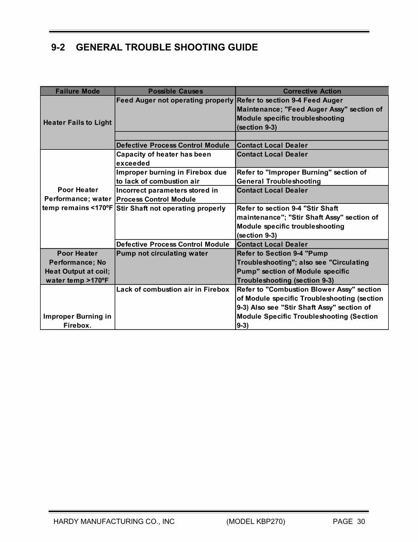
9-2 GENERAL TROUBLE SHOOTING GUIDE
Failure Mode Possible Causes Corrective Action
Feed Auger not operating properly Refer to section 9-4 Feed Auger
Maintenance; "Feed Auger Assy" section of
Module specific troubleshooting
(section 9-3)
Defective Process Control Module Contact Local Dealer
Capacity of heater has been
exceeded
Contact Local Dealer
Improper burning in Firebox due
to lack of combustion air
Refer to "Improper Burning" section of
General Troubleshooting
Incorrect parameters stored in
Process Control Module
Contact Local Dealer
Stir Shaft not operating properly Refer to section 9-4 "Stir Shaft
maintenance"; "Stir Shaft Assy" section of
Module specific troubleshooting
(section 9-3)
Defective Process Control Module Contact Local Dealer
Poor Heater
Performance; No
Heat Output at coil;
water temp >170ºF
Pump not circulating water Refer to Section 9-4 "Pump
Troubleshooting"; also see "Circulating
Pump" section of Module specific
Troubleshooting (section 9-3)
Improper Burning in
Firebox.
Lack of combustion air in Firebox Refer to "Combustion Blower Assy" section
of Module specific Troubleshooting (section
9-3) Also see "Stir Shaft Assy" section of
Module Specific Troubleshooting (Section
9-3)
Heater Fails to Light
Poor Heater
Performance; water
temp remains <170ºF

HARDY MANUFACTURING CO., INC (MODEL KBP270) PAGE 31
9-3 MODULE SPECIFIC TROUBLE SHOOTING GUIDE
Module Failure Mode Possible Causes Corrective Action
Shaft set screw loose verify set screw is tight against shaft
Motor gears locked or stripped Replace motor
Defective Motor Test Motor with supplied test cord. If blower
does not operate then replace. (see section
9-4)
Defective Process Control Relay Trace wiring to control panel according to
wiring diagram
Defective Process Control Module Contact Local Dealer and request new
Process Control Module
Excessive Moisture in fuel causing
clumps that will not pass through
Tube
Defective Motor Test Motor with supplied test cord. If blower
does not operate then replace. (see section
9-4)
Defective Process Control Relay
Defective Process Control Module Contact Local Dealer
Power at motor
connection but
Combustion Blower
does not operate
Defective blower Test Blower with supplied test cord. If
blower does not operate then replace. (see
section 9-4)
Defective Process Control Relay
Defective Process Control Module Contact Local Dealer
Stir shaft finger orifices blocked Clear orifices (see section 9-4)
Excessive Ash buildup in Firebox
Chamber
Remove Ash Buildup from firebox. Refer to
Section VIII; 8-2
Defective pump cartridge Replace cartridge (see section 9-4; Pump
troubleshooting)
Defective pump capacitor Replace capacitor (see section 9-4; Pump
troubleshooting)
Defective pump motor winding Replace Pump (see section 9-4; Pump
troubleshooting)
No Power at motor
connection
Combustion
Blower
Assy
No Power at motor
connection
Lack of Combustion
air in Firebox Burn
Chamber
Circulating
Pump
Power at outlet but
pump does not
operate
Stir
Shaft
Assy
Motor Operates but
shaft does not rotate
No Power at motor
connection
Power at motor
connection but motor
does not operate
Feed
Auger
Assy
HARDY MANUFACTURING CO., INC (MODEL KBP270) PAGE 32
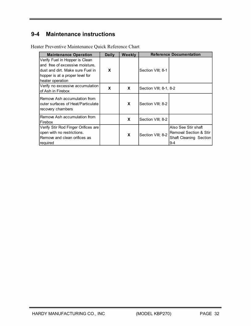
9-4 Maintenance instructions
Maintenance Operation Daily Weekly
Verify Fuel in Hopper is Clean
and free of excessive moisture,
dust and dirt. Make sure Fuel in
hopper is at a proper level for
heater operation
X Section VIII; 8-1
Verify no excessive accumulation
of Ash in FireboxX X Section VIII; 8-1, 8-2
Remove Ash accumulation from
outer surfaces of Heat/Particulate
recovery chambers
X Section VIII; 8-2
Remove Ash accumulation from
FireboxX Section VIII; 8-2
Verify Stir Rod Finger Orifices are
open with no restrictions.
Remove and clean orifices as
required
X Section VIII; 8-2
Also See Stir shaft
Removal Section & Stir
Shaft Cleaning Section
9-4
Reference Documentation
Heater Preventive Maintenance Quick Reference Chart

HARDY MANUFACTURING CO., INC (MODEL KBP270) PAGE 33
9-4 Maintenance Instructions (continued) Feed Auger complete removal instructions
Step # Operation Description Visual Aids/Comments
1Remove Rear Access Panel and set aside
in a location to prevent damage.
2
Disconnect the Auger Power Connector. It
will be the connector identified with Blue
Tape.
3
Remove the Lock Nut from the Auger
Conduit Connector and remove from Hull
Assembly.
4
Using a 7/16" socket wrench or other
suitable tool, Loosen and remove the (qty
4) Hex nut from the underside of Feed
Auger Hopper Top as Shown.
5
Loosen the 2" Union located just in front of
the Auger Hopper.
Warning: Heater should be shut down and allowed ample time for the
Firebox to cool prior to performing this maintenance operation.

HARDY MANUFACTURING CO., INC (MODEL KBP270) PAGE 34
9-4 Maintenance Instructions (continued) Feed Auger complete removal instructions (continued)
Step # Operation Description Visual Aids/Comments
6
when the 2" Union is disengaged allow the
hopper to drop down then pull the
assembly toward you as shown.
Completely remove the assembly from the
Furnace.
7
Remove the Auger by rotating the
Assemby counterclockwise until the
assembly is disengaged from the Auger
Adapter Fitting located on the Rear of the
Furnace.
8
Pull the assembly away from Furnace
Adapter coupling and then pull through the
Hull Opening. Use caution when pulling the
assembly through the Hull Opening to
prevent damage to the Hull.
9 Reinstall in reverse order.

HARDY MANUFACTURING CO., INC (MODEL KBP270) PAGE 35
9-4 Maintenance Instructions (continued) Feed Auger Drive Shaft and Flighting Removal
Step # Operation Description Visual Aids/Comments
1
Remove the protective cover from Feed
Auger Motor assembly by removing the two
wing nuts and lifting the cover off.
2
Disconnect the power connector and set
the cover aside.
3
To remove the motor assembly from the
Auger Hopper Tube Assembly rotate the
Motor Assembly in a counterclockwise
rotation.
4
When the threads on the Motor Assembly
Coupling are disengaged from the Auger
Tube Assembly the Motor and Flighting
can be completely removed from the tube
by pulling toward you.
5
To Remove the Auger Drive Shaft and
Flighting Assemblies Loosen the Motor Set
Screw using a 7/16" wrench.
WARNING: THE HEATER SHOULD BE SHUT DOWN AND ALLOWED
AMPLE TIME FOR THE FIREBOX TO COOL PRIOR TO PERFORMING
THIS MAINTENANCE OPERATION.

HARDY MANUFACTURING CO., INC (MODEL KBP270) PAGE 36
9-4 Maintenance Instructions (continued)
Feed Auger Drive Shaft and Flighting Removal (Continued)
Step # Operation Description Visual Aids/Comments
6
Pull the motor from the shaft.
7
Remove the shaft collar and set aside.
8
Pull the Drive Shaft and Flighting
assemblies from the Motor Mount Housing.
9
To remove the flighting from the Drive Shaft
loosen the flighting clamp using a 7/16"
wrench as shown. Loosen the screws until
the flighting will rotate out of the clamp. To
reinstall rotate the flighting under the clamp
and turn until the end of the flighting
contacts the shaft collar. Then tighten the
7/16" set screws on the clamp.
10 Re-assemble in reverse order.
HARDY MANUFACTURING CO., INC (MODEL KBP270) PAGE 37
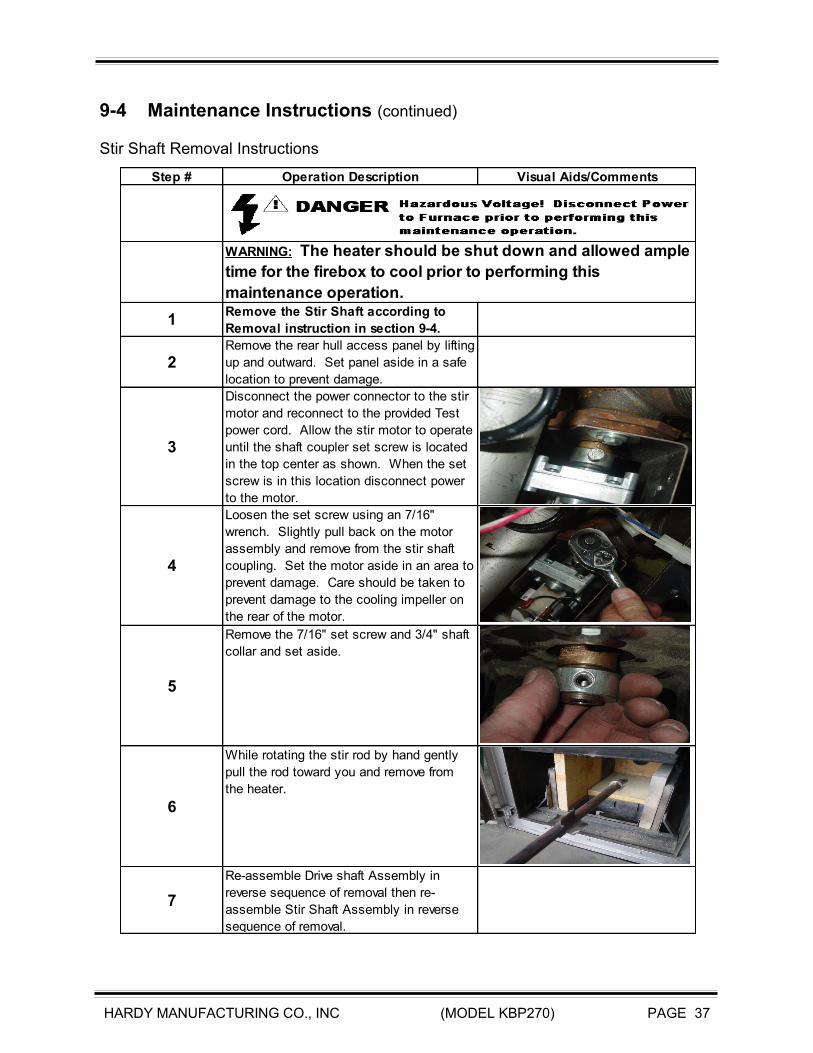
9-4 Maintenance Instructions (continued) Stir Shaft Removal Instructions
Step # Operation Description Visual Aids/Comments
1Remove the Stir Shaft according to
Removal instruction in section 9-4.
2Remove the rear hull access panel by lifting
up and outward. Set panel aside in a safe
location to prevent damage.
3
Disconnect the power connector to the stir
motor and reconnect to the provided Test
power cord. Allow the stir motor to operate
until the shaft coupler set screw is located
in the top center as shown. When the set
screw is in this location disconnect power
to the motor.
4
Loosen the set screw using an 7/16"
wrench. Slightly pull back on the motor
assembly and remove from the stir shaft
coupling. Set the motor aside in an area to
prevent damage. Care should be taken to
prevent damage to the cooling impeller on
the rear of the motor.
5
Remove the 7/16" set screw and 3/4" shaft
collar and set aside.
6
While rotating the stir rod by hand gently
pull the rod toward you and remove from
the heater.
7
Re-assemble Drive shaft Assembly in
reverse sequence of removal then re-
assemble Stir Shaft Assembly in reverse
sequence of removal.
WARNING: The heater should be shut down and allowed ample
time for the firebox to cool prior to performing this
maintenance operation.
HARDY MANUFACTURING CO., INC (MODEL KBP270) PAGE 38
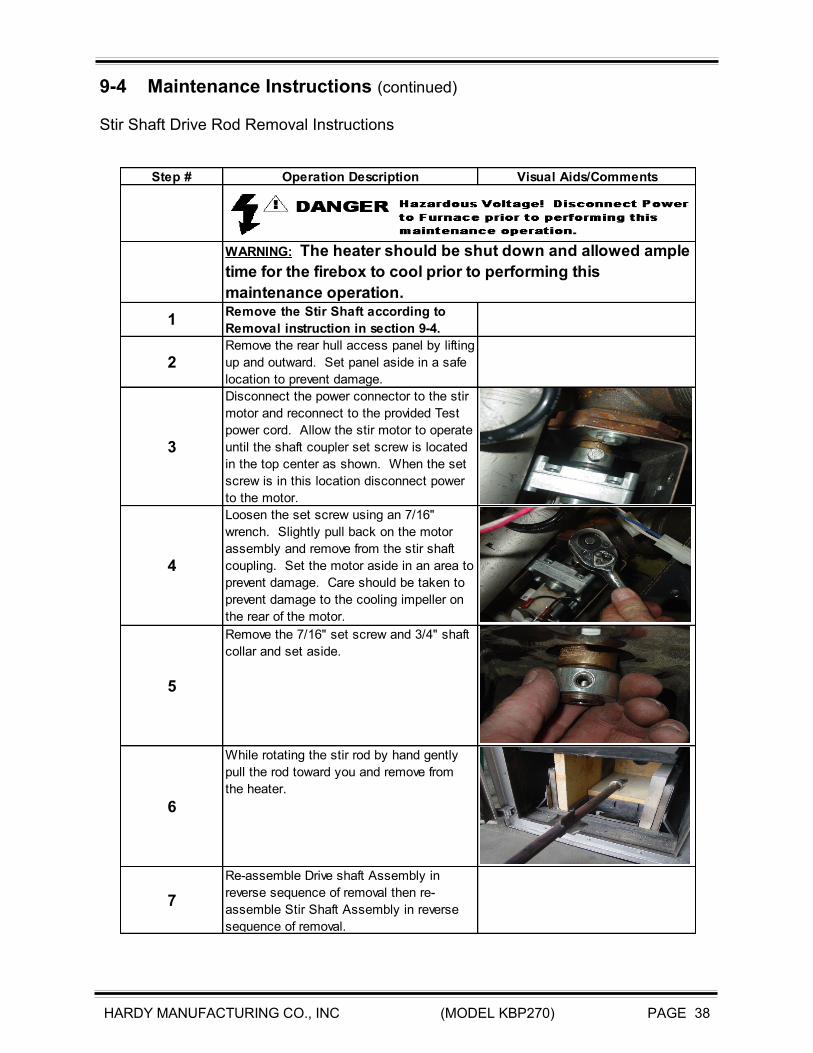
9-4 Maintenance Instructions (continued) Stir Shaft Drive Rod Removal Instructions
Step # Operation Description Visual Aids/Comments
1Remove the Stir Shaft according to
Removal instruction in section 9-4.
2Remove the rear hull access panel by lifting
up and outward. Set panel aside in a safe
location to prevent damage.
3
Disconnect the power connector to the stir
motor and reconnect to the provided Test
power cord. Allow the stir motor to operate
until the shaft coupler set screw is located
in the top center as shown. When the set
screw is in this location disconnect power
to the motor.
4
Loosen the set screw using an 7/16"
wrench. Slightly pull back on the motor
assembly and remove from the stir shaft
coupling. Set the motor aside in an area to
prevent damage. Care should be taken to
prevent damage to the cooling impeller on
the rear of the motor.
5
Remove the 7/16" set screw and 3/4" shaft
collar and set aside.
6
While rotating the stir rod by hand gently
pull the rod toward you and remove from
the heater.
7
Re-assemble Drive shaft Assembly in
reverse sequence of removal then re-
assemble Stir Shaft Assembly in reverse
sequence of removal.
WARNING: The heater should be shut down and allowed ample
time for the firebox to cool prior to performing this
maintenance operation.
HARDY MANUFACTURING CO., INC (MODEL KBP270) PAGE 39
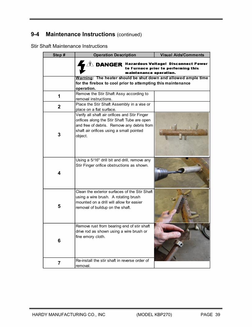
9-4 Maintenance Instructions (continued) Stir Shaft Maintenance Instructions
Step # Operation Description Visual Aids/Comments
1Remove the Stir Shaft Assy according to
removal instructions.
2Place the Stir Shaft Assembly in a vise or
place on a flat surface.
3
Verify all shaft air orifices and Stir Finger
orifices along the Stir Shaft Tube are open
and free of debris. Remove any debris from
shaft air orifices using a small pointed
object.
4
Using a 5/16" drill bit and drill, remove any
Stir Finger orifice obstructions as shown.
5
Clean the exterior surfaces of the Stir Shaft
using a wire brush. A rotating brush
mounted on a drill will allow for easier
removal of buildup on the shaft.
6
Remove rust from bearing end of stir shaft
drive rod as shown using a wire brush or
fine emory cloth.
7Re-install the stir shaft in reverse order of
removal.
Warning: The heater should be shut down and allowed ample time
for the firebox to cool prior to attempting this maintenance
operation.

HARDY MANUFACTURING CO., INC (MODEL KBP270) PAGE 40
9-4 Maintenance Instructions (continued) Pump Maintenance instructions
Step # Operation Description Visual Aids/Comments
Testing/Replacing Pump Cartridge
1Close the pump inlet and return ball valves to prevent
water flow.
2
Loosen and remove the four(4) 7/16" screws from the
pump motor housing using a 7/16" socket wrench or
other suitable tool.
3Gently pull the pump motor housing toward you and turn
so you can view pump impellar.
4Rotate the pump impellar by hand. If the impellar will
not spin freely then replace the cartridge.
5 Reassemble in reverse order.
Testing Pump Capacitor
1 Remove top cover to expose electrical connections.
2
If using an analog Ohm meter, check the resistance
across the two capacitor leads. The meter should
immediately read "0" Ohms then slowly drift to infinity.
Reverse the test leads and check meter reading. The
test procedure is the same for a digital multimeter
except the meter will show some resistance then return
to "OL" (open line. To replace Capacitor, cut away
existing wire nut connectors. strip leads and connect
with wire nut connector suitable for two(2) 16 AWG
wires.
3 Replace cover.
Testing Pump Motor Winding
1
Disconnect power cord from motor wiring. Using an
Ohm meter or continuity tester, check the continuity
across each power wire and also check each power wire
to ground. If the the pump does not show continuity
across the two power wires or if either power wire shows
continuity to ground the winding is defective and the
pump should be replaced.
Warning: The heater should be shutdown and allowed ample time for the Firebox to
cool prior to performing this maintenance operation.