photodegradation of uhmwpe filled with iron ore fine · photodegradation of uhmwpe filled with iron...
TRANSCRIPT

DOI: http://dx.doi.org/10.1590/1980-5373-MR-2016-0320Materials Research. ©
Photodegradation of UHMWPE Filled with Iron Ore Fine
Frederick Louis Dias de Moraisa, Felipe da Silva Medeirosb, Glaura Goulart Silvab, Marcelo Silveira
Rabelloc, Alexandre Rangel de Sousaa*
Received: April 23, 2016; Revised: September 24, 2016; Accepted: December 27, 2016.
Ultra high molecular weight polyethylene (UHMWPE) is one of the most important engineering materials owing to outstanding properties like impact strength and abrasion resistance. However, the relatively low Young´s modulus restricts some application and the use of fillers may be a suitable way to overcome this. The fillers can influence the photo stabilization of the compound, as it occurs to other polymers. Neat UHMWPE and its composites with 1 and 10% of iron ore fine were exposed to ultraviolet radiation for up to 33 days and then tested for mechanical properties. The stress-strain behaviour changed with degradation, with an evident necking and strain hardening region that was not observed before exposure, due to a reduction in entanglements density. From the tensile results, the filler may have a protection action against UV, particularly when a loading of 10% was present. Complementary analyses were performed, including X-ray diffraction, DSC and SEM.
Keywords: Iron ore fine, Photodegradation, UHMWPE
* e-mail: [email protected]
1. Introduction
Ultra high molecular weight polyethylene (UHMWPE) is rather similar to high-density polyethylene (HDPE) based on the chemical structure and molecular architecture1,2. Such as HDPE, it can be synthetized as an homopolymer, being predominantly linear, or as a copolymer of ethylene and other olefins, having some small side branches3. However, because of the very high molar mass that results on special properties like high impact strength and abrasion resistance, UHMWPE is classified as an engineering polymer4, whereas HDPE is considered a commodity5. UHMWPE is applied, among others, as internal human body prosthesis, which prompted several studies on the gamma radiation and electron beam effects on its properties6,7,8. These radiations are used for sterilization and to promote crosslinking, improving the wear strength9,10,4. As an engineering plastic, UHMWPE is also widely used outdoors and, hence, the chemical stability under UV radiation is very important. Although not many studies were conducted on this issue, it was shown that the degradation behaviour of UHMWPE is similar to HDPE, except for mobility differences of free radicals due the difference in molecular sizes of these two polymers11,12.
One of the disadvantages of UHMWPE in comparison with other engineering polymers is the relatively low
modulus, and this can be overcome by adding fillers. The use of natural or synthetic fillers, however, can also change the polymer stability against UV radiation and temperature damage, which have been reported in many studies13,14,15,16. For example, Dintcheva et al.17,18 evaluated the anti UV action of a functionalized carbon nanotube (CNT) with a hindered amine light stabilizer and silsesquioxane on an UHMWPE matrix. A significant improvement in UV stabilization was noted when the filler was present.
In this study the influence of iron ore fine on UV stability of UHMWPE was investigated. Although the iron ore fine can be a high value material and, therefore, could be considered inappropriate to be used as a filler, the wastes generated from the mining and ore processing are usually discarded, being a possible industrial filler to UHMWPE. The neat polymer and the compound with 1% and 10% of filler were submitted to UV irradiation for up to 33 days and tested for mechanical and physicochemical changes. To the best of our knowledge, this is the first study using a residue from the mining industry as filler to improve UV stability of UHMWPE.
2. Experimental
The UHMWPE was supplied by Braskem (Brazil) in a powder form, with molar mass 3×10⁶ g/mol and density 0.925 g/cm3. The iron ore fine was supplied by Vale do Rio
aDepartamento de Engenharia de Materiais, Campus I, Centro Federal de Educação Tecnológica de Minas Gerais, Avenida Amazonas, 5253, Belo Horizonte, MG, Brazil
bDepartamento de Química, Instituto de Ciências Exatas, Universidade Federal de Minas Gerais, Avenida Antônio Carlos, 6627, Belo Horizonte, MG, Brazil
cUnidade Acadêmica de Engenharia de Materiais, Universidade Federal de Campina Grande, Avenida Aprígio Veloso, 882, Campina Grande, PB, Brazil
Morais et al.2 Materials Research
Doce Company (Brazil) and it was sifted through an ASTM 100 mesh sieve, with aperture of 0.154mm, to remove coarse particles before mixing with the polymer.
The polymer and iron ore fine were poured in a closed plastic bag for an intense mixing up to homogenization. Besides the neat UHMWPE, two compounds were prepared, containing 1% and 10% of iron ore fine. Plates with sizes of 150mm × 100mm × 1 and 3mm were produced by compression moulding in a Solab hydraulic press at 220°C during 35 minutes under a pressure of 2.7MPa with periodic degassing during the cycle. The cooling of the plates was done at first by leaving them under pressure for 60 minutes after switching off the heat, followed by 40 minutes at room temperature. Test bars were machined from the plates, for characterization.
The X-ray diffraction analysis (XRD) of filler was performed in a Shimadzu XRD-7000 model at 40 KV, 30 mA and using a copper target. The scanning range was from 5 to 80° (2θ) with a rate of 2°/min. The data analysis was performed with the software OriginLab version 7.0 and powder X software, version 2004.04.70 PRO to identify the pattern of diffraction peaks generated. The determination of filler chemical composition was done by energy dispersive X-ray in a Shimadzu EDX-720 equipment using a scanning rate of 0.02°/min, enabling the determination of elements from Ti to U. The image of the UHMWPE powder filled with 10% of iron ore fine was obtained using a SED-X Shimadzu scanning electron microscope.
Type IV tensile bars (ASTM D-638), thickness of 1mm, and impact Charpy specimens (120×12×3mm) were machined from compression-moulded plates. The impact specimens were notched with an angle of 30° and 2mm of depth.
The specimens were exposed to ultraviolet radiation at room temperature using LightTech 80W fluorescent tubes, which are used to artificial sunbath, following a similar procedure used in a previous study19. The exposure times were defined as 11, 22 and 33 days.
Tensile tests before and after UV irradiation were conducted in a Shimadzu tensile test machine using a crosshead speed of 50 mm/min at 23°C with at least 6 specimens for each condition. The impact Charpy was done on a XJ25-Z equipment using a 25J hammer.
FTIR spectra from UV exposed surfaces were obtained using a Shimadzu Prestige 21 spectrophotometer with a horizontal ATR accessory. Carbonyl index (CI) was determined through the equation (1):
Where A1731 and A1370 are the band areas of carbonyl and methyl groups, respectively. The last one was used as internal standard band.
Differential scanning calorimetry (DSC) was used to evaluate the crystallinity degree of neat polymer and their compounds with iron ore fine after UV irradiation. The
measurements were performed in a TA Instruments 2920 calorimeter. The samples were removed from a micrometric layer from exposed surface and the data were obtained from the first heating using a heating rate of 10°C/min. For selected compositions the tests were performed in duplicate, indicating differences between data of crystallinity degree from the measurements inferior to 2%.
The morphology in cryogenic fractured specimens before and after UV exposure was inspected by scanning electron microscopy (SEM). The images were obtained with an electron microscope gun of field emission scanning (FEI QUANTA 200) and acquired using the Backscattered Electrons mode (BSE). In the BSE method, the backscattered electrons are originated from the interaction of the emitted beam by the electronic microscope with the nuclei of atoms in the samples. As the intensity of this interaction depends largely on the nuclear charge (Rutherford scattering type), chemical contrast is most evident in these images, enabling a better assessment to the dispersion of iron ore fine in the composite. Through these analyses, the evaluation of particles morphology size distribution is possible.
3. Results
3.1 Iron ore fine characterization
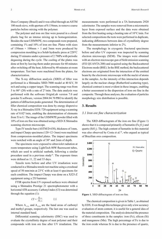
The XRD diffractogram of the iron ore fine (Figure 1) shows that it is composed primarily of hematite (Fe2O3) and quartz (SiO2). The high content of hematite in this material was also observed by Costa et al.20, who argued as typical of Brazilian ores composition.
( )CI AA 1
1370
1731=
Figure 1. XRD diffractogram of iron ore fine.
The chemical composition is given in Table 1, as obtained by EDX. Even though this technique gives only a low accuracy evaluation of atom content, it is useful for a general idea of the material composition. The analysis detected the presence of three constituents in the samples: iron (Fe), silicon (Si) and manganese (Mn). The high percentage of Fe is due to the iron oxide whereas Si is due to the presence of quartz,

3Photodegradation of UHMWPE Filled with Iron Ore Fine
which is consistent with the results of XRD. Mn is the lowest percentage element (<1%) and it was not observed in the XRD diffractogram. The presence of Mn might be due to the occurrence of substitution manganese hematite structures as a result of environmental weathering21.
Table 1: Chemical composition of iron ore fine obtained from EDX analysis.
Chemical element Composition (%)
Fe 88,6
Si 10,5
Mn 0,8
The morphology of the filler particles was assessed by the SEM analysis of the composite fracture surface, as shown in Figure 2. The quartz particles have a more compact morphology whereas hematite is more granular. The average area of the particles is approximately 0.2 mm2, as given in the histogram. Although they have an irregular format, if we consider the disc form the average diameter equivalent is 0.5mm, that is higher than 0.154mm, the aperture of the sieve. This can be explained for some agglomeration during the moulding process or the elongated format of the particles.
Figure 2. SEM and BSE images of the fractured surface of composite with 10% of fine iron ore, and histogram of the average size of the particles.
The Figure 3 shows the SEM image obtained from the composition of the polymer with 10% of iron ore fine before moulding where we can see that the iron ore fine particles, indicated by white arrows, barely have the size higher than 0.1mm.
3.2 Mechanical properties
Tensile tests, crystallinity and oxidation
The results for ultimate strain of neat UHMWPE and their compounds with iron ore fine before and after UV exposure are shown in Figure 4. For the unexposed samples, the maximum elongation is reduced by about 20% when 10% filler is present. Even so, the value obtained (about 400%) is still higher than the minimum accepted to this grade that is 350%, according to the polymer manufacturer22. It is well known that the presence of particulate fillers in a ductile matrix reduces the elongation because the fillers act as a
Figure 3. SEM image of the UHMWPE powder filled with 10% of iron ore fine.
stress raiser15. Li et al.23 studied the mechanical strength of UHMWPE compounded with 70% charcoal, and observed a reduction on rupture strain of composites. The neat polymer strained 323% and the composites 31%.
Figure 4. Rupture strain with the UV time exposure of UHMWPE and their compounds with 1 and 10% of iron ore fine. Surigo usar nas abcissas “Filler content (%)”.
Figure 4 also shows that after UV exposure, the rupture strain of neat UHMWPE changed significantly, rising 27% at first up to 22 days exposure, then an abrupt drop was observed. A similar behavior was observed to the polymer compounded with 1% of iron ore fine in which the rupture strain raised 34% up to 22 days exposure then a reduction was observed, though far less in comparison to neat polymer. The polymer containing 10% of iron ore fine showed the lowest variation of maximum elongation with UV exposure time, indicating the stabilizing action of the filler. A high dispersion on rupture strain results was noted for the neat polymer after 33 days UV exposure since some specimens fractured during necking while some of them stabilized the necking process and strained a higher percent before
Morais et al.4 Materials Research
rupture. There are some studies showing that mineral fillers can protect the polymeric matrix against the UV radiation but, in some cases, the filler may contain active metal that act as a catalyst to polymer degradation5,14. Grigoriadou et al.24 observed that Cu-nanofiber protected HDPE against UV radiation by reducing the oxygen diffusion through the sample. In other work, Grigoriadou et al.25 showed that some nanoparticles added to HDPE promoted stabilization whereas others accelerated the photo-oxidation process.
It could be expected that the changes that occurred on rupture strain by UV action were towards the reduction on this property, not the increase as noted in some conditions (Figure 4). Actually, one of the most common evidences of polymer deterioration by photodegradation is the reduction in elongation26, which is explained by the molecular scission and entanglement density reduction that can also cause an increase in crystallinity in semi-crystalline polymers26,27,28. The results showed in Figure 4, specially to neat polymer and to the compound with 1% iron ore fine, up to 22 days exposure are surprising at first sight because an increase on rupture strain was clearly noted. We believe that the high entanglement density of UHMWPE may be the key to understand this behaviour. The stress strain curves presented by the degraded neat polymer and the compound with 1% filler (to be discussed in detail further in this text) are somewhat similar to the HDPE behaviour, which has a higher elongation in comparison to UHMWPE. It is believed that the very high entanglement density of UHMWPE restricts the elongation. In this way, we suppose that the molecular scissions that take place during exposure reduce the entanglement density and, hence, allow a higher elongation, similar to HDPE. However, it is important to highlight that there is a profile of degradation on thick samples like those used here. This is because of oxygen access vary through the thickness, making degradation more intense near the exposed surface29. Despite the heterogeneous profile, the resultant behaviour on stress strain test of degraded samples was much similar to that presented by HDPE, including the necking on yield point and the cold drawing region that are not normally presented during UHMWPE tests4,30. These differences are assigned to the higher entanglement density on the last one31. It is important to emphasize that HDPE is also more crystalline than UHMWPE30. Another aspect that should be considered to explain those results is the possibility of crosslinking of polyethylene, particularly if the oxygen is absent, for example, in internal regions of the specimen11.
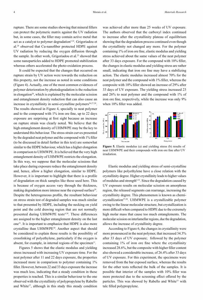
Figures 5 shows that the elastic modulus and yielding stress increased with increasing UV exposure time. For the neat polymer after 11 and 22 days exposure, the properties increased more in comparison to polymer containing 1% filler. However, between 22 and 33 days exposure the increase was much less, indicating that a steady condition in these properties is reached. This is a similar behaviour to the one observed with the crystallinity of polypropylene by Rabello and White27, although in this study this steady condition
was achieved after more than 25 weeks of UV exposure. The authors observed that the carboxyl index continued to increase after the crystallinity plateau of equilibrium showing that the degradation process continued even though the crystallinity not changed any more. For the polymer containing 1% of iron ore fine, elastic modulus and yielding stress achieved about the same values of the neat polymer after 33 days exposure. For the compound with 10% filler, the changes in elastic modulus and yielding stress are rather small, indicating that iron ore fine may have a stabilizing action. The elastic modulus increased almost 70% for the neat polymer and the compound with 1% filler, whereas the composite with 10% filler showed an increase of 29% after 33 days of UV exposure. The yielding stress increased 23 and 26% to neat polymer and the compound with 1% of iron ore fine, respectively, while the increase was only 9% when 10% filler was added.
Figure 5. Elastic modulus (a) and yielding stress (b) results of neat UHMWPE and their compounds with iron ore fine after UV irradiation.
Elastic modulus and yielding stress of semi-crystalline polymers like polyethylene have a close relation with the crystallinity degree. Higher crystallinity leads to higher values of modulus and strength5,32. Since the degradation caused by UV exposure results on molecular scission on amorphous region, the released segments can rearrange, increasing the crystallinity degree. This phenomenon is known as chemi-crystallization27,28. UHMWPE is a crystallizable polymer owing to the linear molecular structure, but crystallization is more difficult when compared to HDPE due to the extremely high molar mass that cause too much entanglements. The molecular scission on interlamellar regions, due the degradation, allows the increase of crystallinity degree.
According to Figure 6, the changes in crystallinity were more pronounced in the neat polymer, that increased 34.3% after 33 days of UV exposure; followed by the polymer containing 1% of iron ore fine where the crystallinity increased 28.6%, but the composite with higher filler content also showed a considerable increase, of 26.4% after 33 days of UV exposure. For this experiment, the specimens were removed from the bar exposed surface, whereas the results for the other tests reflected the bulk of the samples. It is possible that interior of the samples with 10% filler was more protected due to the screening effect offered by the particles. This was showed by Rabello and White33 with talc filled polypropylene.

5Photodegradation of UHMWPE Filled with Iron Ore Fine
when the yielding point is reached, which would be due to the necking of the sample bar30. Actually, no necking was visually observed during the test. After the yielding point, the curve presents a steady increases on stress up to fracture without the development of a cold drawing region. These two aspects, absence of necking after yielding point and hardening strain, are assigned to a high density of entanglements36,37,38,39 because of the high molecular weight of UHMWPE. With the increase of UV exposure, a significant stress drop is noted after the yielding point, which caused necking of the samples, followed by a cold drawing region that is more extensive for longer exposures. The strain hardening is still observed for samples exposed for 11 and 22 days. The behaviour of these samples is similar to the one observed for HDPE38, probably due to the reduction of entanglements density as considered previously. For 33 days of UV exposure, the majority of the samples fractured close to the yielding region.
The stress-strain curves for the 1% filled polymer (Figure 7-b) were similar to ones for the neat polymer, like the occurrence of necking on yielding point, a cold drawing region and the hardening strain at the end of the test. For 33 days of UV exposure, about 85% of the samples dit not fractured on yielding point, developing cold drawing. This percentange was higher in comparison to neat polymer exposed to UV radiation by the same time, indicating some stabilization promoted by the filler.
The behaviour described above for the neat polymer and composite with 1% filler occurred also with the 10% filled compound, though in a subtle way (Figure 7-c). There was no rupture on yielding point for samples exposed to 33 days, probably due to the protection against photodegradation this filler promoted to the polymer.
From the plastic region of stress-strain curves three important data were obtained: (i) the drop on stress value after the yield point, (ii) the slope between 100 and 200% elongation and (iii) the slope between 300 and 400% elongation, and the results are given in Figure 8. Figure 8-a shows that stress drop is higher for the neat polymer and a minor change was observed for the polymer containing 10% filler; the compound with 1% of filler showed an intermediate behaviour. The increase in stress drop after yielding with exposure is a consequence of the reduction in entanglement density and a crystallinity increase, as discussed previously.
Figure 6. Crystallinity degree of neat UHMWPE and their compounds with iron ore fine after UV irradiation. The accuracy of the data was obtained for selected samples and is ± 2%.
Although the photodegradation of polyolefins like UHMWPE is followed by the increase of carbonyl index, in this study this wasn’t observed, as shown in the Table 2. Studies of measures of carbonyl index through FTIR in polyolefins indicates an interval before the detection of the increase of oxidation, wich one increases if a stabilizer is used34. Fernando et al.35 after comparing two different ways of measuring the oxidation of polyethylene and propylene concluded that while it is necessary more than one hundred hours of UV exposure to get a measurable concentration of carbonyl groups in a conventional test only a few minutes are necessary to detect the CO2 evolved in gas tests.
Table 2: Carbonyl index.
SampleCI
unexposed 33 days
0% fine 0.067 0.028
1% fine 0.033 0.028
10% fine 0.097 0.037
Plastic region of stress strain curves
Figure 7-a shows representative curves for unexposed and UV irradiated neat UHMWPE. For the unexposed polymer the curve does not have a visible drop on stress
Figure 7. Representative stress strain curves of UHMWPE exposed for various times : (a) neat; (b) UHMWPE with 1% of iron ore fine; (c) UHMWPE with 10% of iron ore fine. Inset shows a magnification of the yielding region.
Morais et al.6 Materials Research
Figure 8. Data obtained from stress strain curves: (a) drop on stress after the yielding; (b) slope of curve between 100 and 200% of strain; and (c) slope between 300 and 400% of strain.
The reduction of slope between 100 and 200% of strain (Figure 8-b) is also a consequence of a change of entanglement network, with the appearance of a cold drawing region as the degradation increases. It results that the deformation becomes easier when less entanglements are present. The slope between 300 and 400% (Figure 8-c) is related to the extension of cold drawing, following the same trend shown in Figure 8-b.
Impact Tests Results
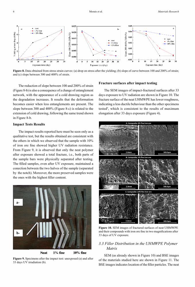
The impact results reported here must be seen only as a qualitative test, but the results obtained are consistent with the others in which we observed that the sample with 10% of iron ore fine showed higher UV radiation resistance. From Figure 9, it is observed that only the neat polymer after exposure showed a total fracture, i.e., both parts of the sample bars were physically separated after testing. The filled samples, even after UV exposure, maintained a conection between the two halves of the sample (separated by the notch). Moreover, the more preserved samples were the ones with the highest filler content.
Figure 9. Specimens after the impact test: unexposed (a) and after 33 days UV irradiation (b).
Fracture surfaces after impact testing
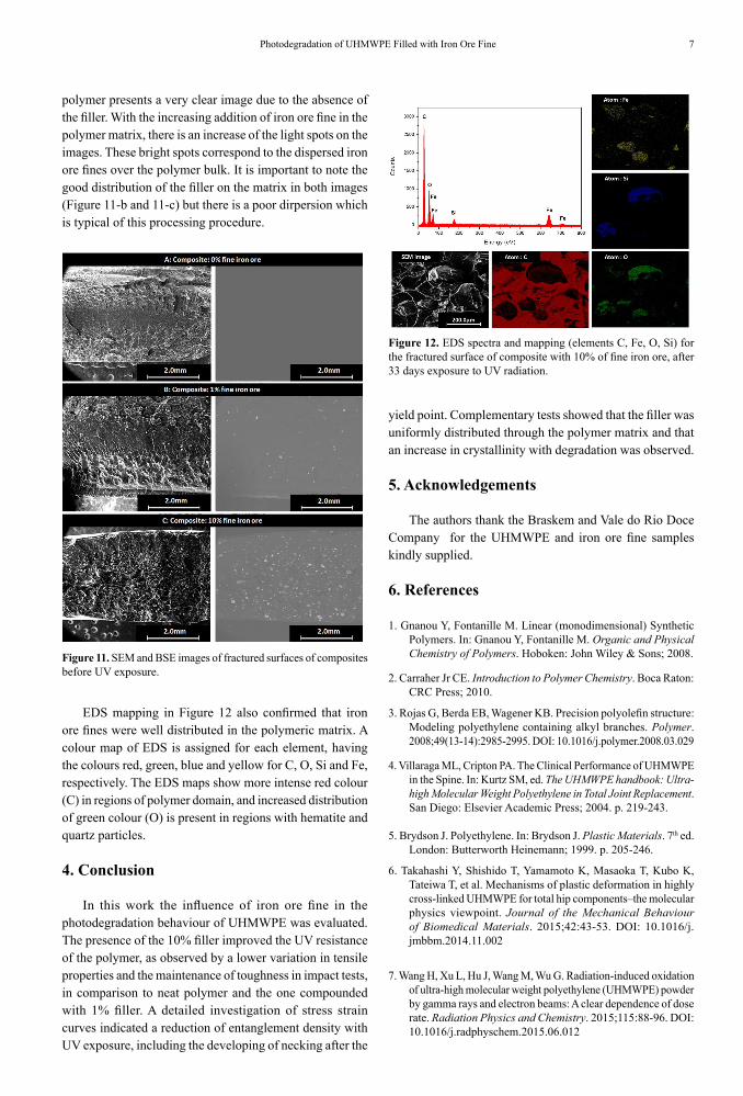
The SEM images of impact-fractured surfaces after 33 days exposure to UV radiation are shown in Figure 10. The fracture surface of the neat UHMWPE has lower roughness, indicating a less ductile behaviour than the other specimens tested9, which is consistent to the results of maximum elongation after 33 days exposure (Figure 4).
Figure 10. SEM images of fractured surfaces of neat UHMWPE and their compounds with iron ore fine in two magnifications after 33 days of UV exposure.
3.3 Filler Distribution in the UHMWPE Polymer Matrix
SEM (as already shown in Figure 10) and BSE images of the materials studied here are shown in Figure 11. The BSE images indicates location of the filler particles. The neat
7Photodegradation of UHMWPE Filled with Iron Ore Fine
polymer presents a very clear image due to the absence of the filler. With the increasing addition of iron ore fine in the polymer matrix, there is an increase of the light spots on the images. These bright spots correspond to the dispersed iron ore fines over the polymer bulk. It is important to note the good distribution of the filler on the matrix in both images (Figure 11-b and 11-c) but there is a poor dirpersion which is typical of this processing procedure.
Figure 11. SEM and BSE images of fractured surfaces of composites before UV exposure.
EDS mapping in Figure 12 also confirmed that iron ore fines were well distributed in the polymeric matrix. A colour map of EDS is assigned for each element, having the colours red, green, blue and yellow for C, O, Si and Fe, respectively. The EDS maps show more intense red colour (C) in regions of polymer domain, and increased distribution of green colour (O) is present in regions with hematite and quartz particles.
4. Conclusion
In this work the influence of iron ore fine in the photodegradation behaviour of UHMWPE was evaluated. The presence of the 10% filler improved the UV resistance of the polymer, as observed by a lower variation in tensile properties and the maintenance of toughness in impact tests, in comparison to neat polymer and the one compounded with 1% filler. A detailed investigation of stress strain curves indicated a reduction of entanglement density with UV exposure, including the developing of necking after the
Figure 12. EDS spectra and mapping (elements C, Fe, O, Si) for the fractured surface of composite with 10% of fine iron ore, after 33 days exposure to UV radiation.
yield point. Complementary tests showed that the filler was uniformly distributed through the polymer matrix and that an increase in crystallinity with degradation was observed.
5. Acknowledgements
The authors thank the Braskem and Vale do Rio Doce Company for the UHMWPE and iron ore fine samples kindly supplied.
6. References
1. Gnanou Y, Fontanille M. Linear (monodimensional) Synthetic Polymers. In: Gnanou Y, Fontanille M. Organic and Physical Chemistry of Polymers. Hoboken: John Wiley & Sons; 2008.
2. Carraher Jr CE. Introduction to Polymer Chemistry. Boca Raton: CRC Press; 2010.
3. Rojas G, Berda EB, Wagener KB. Precision polyolefin structure: Modeling polyethylene containing alkyl branches. Polymer. 2008;49(13-14):2985-2995. DOI: 10.1016/j.polymer.2008.03.029
4. Villaraga ML, Cripton PA. The Clinical Performance of UHMWPE in the Spine. In: Kurtz SM, ed. The UHMWPE handbook: Ultra-high Molecular Weight Polyethylene in Total Joint Replacement. San Diego: Elsevier Academic Press; 2004. p. 219-243.
5. Brydson J. Polyethylene. In: Brydson J. Plastic Materials. 7th ed. London: Butterworth Heinemann; 1999. p. 205-246.
6. Takahashi Y, Shishido T, Yamamoto K, Masaoka T, Kubo K, Tateiwa T, et al. Mechanisms of plastic deformation in highly cross-linked UHMWPE for total hip components–the molecular physics viewpoint. Journal of the Mechanical Behaviour of Biomedical Materials. 2015;42:43-53. DOI: 10.1016/j.jmbbm.2014.11.002
7. Wang H, Xu L, Hu J, Wang M, Wu G. Radiation-induced oxidation of ultra-high molecular weight polyethylene (UHMWPE) powder by gamma rays and electron beams: A clear dependence of dose rate. Radiation Physics and Chemistry. 2015;115:88-96. DOI: 10.1016/j.radphyschem.2015.06.012

Morais et al.8 Materials Research
8. George A, Ngo HD, Bellare A. Influence of crystallization conditions on the tensile properties of radiation crosslinked, vitamin E stabilized UHMWPE. Journal of the Mechanical Behaviour of Biomedical Materials. 2014;40:406-412. DOI: 10.1016/j.jmbbm.2014.09.011
9. McKeen LW. Plastics Used in Medical Devices. In: Modjarrad K, Ebnesajjad S. Handbook of Polymer Applications in Medicine and Medical Devices. Oxford: Elsevier; 2014. p. 21-53.
10. Lu S, Buchanan FJ, Orr JF. Analysis of variables influencing the accelerated ageing behaviour of ultra-high molecular weight polyethylene (UHMWPE). Polymer Testing. 2002;21(6):623-631. DOI: 10.1016/S0142-9418(01)00134-9
11. Costa L, Bracco P. Mechanisms of Crosslinking and Oxidative Degradation of UHMWPE. In: Kurtz SM, ed. The UHMWPE Handbook: Ultra-High Molecular Weight Polyethylene in total joint replacement. San Diego: Elsevier Academic Press; 2004. p. 245-261.
12. Costa L, Luda MP, Trossarelli L. Ultra high molecular weight polyethylene–II. Thermal- and photo-oxidation. Polymer Degradation and Stability. 1997;58(1-2):41-54. DOI: 10.1016/S0141-3910(97)00010-4
13. Butylina S, Martikka O, Karki T. Weathering properties of coextruded polypropylene-based composites containing inorganic pigments. Polymer Degradation and Stability. 2015;120:10-16. DOI: 10.1016/j.polymdegradstab.2015.06.004
14. Yang R, Yu J, Liu Y, Wang K. Effects of inorganic fillers on the natural photo-oxidation of high-density polyethylene. Polymer Degradation and Stability. 2005;88(2):333-340. DOI: 10.1016/j.polymdegradstab.2004.11.011
15. Trotignon JP, Demdoum L, Verdu J. Effect of mineral fillers in low concentration on the mechanical properties of polymeric materials. Part 1: Static and fatigue fracture of polypropylene, qualitative aspects. Composites. 1992;23(5):313-318. DOI: 10.1016/0010-4361(92)90330-W. DOI:10.1016/0010-4361(92)90330-W
16. Sharma N, Chang LP, Chu YL, Ismail H, Ishiaku US, Mohd Ishak ZA. A study on the effect of pro-oxidant on the thermo-oxidative degradation behaviour of sago starch filled polyethylene. Polymer Degradation and Stability. 2001;71(3):381-393. DOI: 10.1016/S0141-3910(00)00189-0
17. Dintcheva NTz, Arrigo R, Morici E, Gambarotti C, Carroccio S, Cicogna F, et al. Multi-functional hindered amine light stabilizers-functionalized carbon nanotubes for advanced ultra-high molecular weight polyethylene-based nanocomposites. Composites Part B: Engineering. 2015;82:196-204. DOI: 10.1016/j.compositesb.2015.07.017
18. Dintcheva NTz, Arrigo R, Carroccio S, Curcuruto G, Guenzi M, Gambarotti C, et al. Multi-functional polyhedral oligomeric silsesquioxane-functionalized carbon nanotubes for photo-oxidative stable Ultra-High Molecular Weight Polyethylene-based nanocomposites. European Polymer Journal. 2016;75:525-537. DOI: 10.1016/j.eurpolymj.2016.01.002
19. Sousa AR, Amorim KLE, Medeiros ES, Mélo TJA, Rabello MS. The combined effect of photodegradation and stress cracking in
polystyrene. Polymer Degradation and Stability. 2006;91(7):1504-1512. DOI: 10.1016/j.polymdegradstab.2005.10.002
20. da Costa GM, Barrón V, Ferreira CM, Torrent J. The use of diffusive reflectance spectroscopy for the characterization of iron ores. Minerals Engineering. 2009;22(14):1245-1250. DOI: 10.1016/j.mineng.2009.07.003
21. da Costa MI, Kunrath JI, Cunha JBM, Moro JT, de Araújo JH. Mösbauer effect characterization of Brazilian iron ores for mining industrial purposes. Nuclear Instruments and Methods in Physics Research Section B: Beam Interactions with Materials and Atoms. 1993;76(1-4):244-245. DOI: 10.1016/0168-583X(93)95196-C
22. Braskem. Utec. Ultra high molecular weight; 2015. Available from: < http://www.braskem.com.br/Portal/Principal/Arquivos/Download/Upload/Bras2011_UTEC_ING_20042011.pdf >. Access in: 10/15/2015.
23. Li S, Li X, Deng Q, Li D. Three kinds of charcoal powder reinforced ultra-high molecular weight polyethylene composites with excellent mechanical and electrical properties. Materials and Design. 2015;85:54-59. DOI: 10.1016/j.matdes.2015.06.163
24. Grigoriadou I, Paraskevopoulos KM, Karavasili M, Karagiannis G, Vasileiou A, Bikiaris D. HDPE/Cu-nanofiber nanocomposites with enhanced mechanical and UV stability properties. Composites Part B: Engineering. 2013;55:407-420. DOI: 10.1016/j.compositesb.2013.07.002
25. Grigoriadou I, Paraskevopoulos KM, Chrissafis K, Pavlidou E, Stamkopoulos TG, Bikiaris D. Effect of different nanoparticles on HDPE UV stability. Polymer Degradation and Stability. 2011;96(1):151-163. DOI: 10.1016/j.polymdegradstab.2010.10.001
26. Rabek JF. Experimental methods in polymer degradation. In: Rabek JF. Polymer Photodegradation. Mechanisms and experimental methods. London: Chapman & Hall; 1995. p. 433-597.
27. Rabello MS, White JR. Crystallization and melting behaviour of photodegraded polypropylene – I. Chemi-crystallization. Polymer. 1997;38(26):6379-6387. DOI: 10.1016/S0032-3861(97)00213-9
28. Craig IH, White JR, Kin PC. Crystallization and chemi-crystallization photodegraded polypropylene. Polymer. 2005;46(2):505-512. DOI:10.1016/j.polymer.2004.11.019
29. Schoolenberg GE, Vink P. Ultra-violet degradation of polypropylene: 1. Degradation profile and thickness of the embrittled surface layer. Polymer. 1991;32(3):432-437. DOI: 10.1016/0032-3861(91)90446-Pdoi:10.1016/0032-3861(91)90446-P doi:10.1016/0032-3861(91)90446-P
30. Mohagheghian I, McShane GJ, Stronge WJ. Impact perforation of monolithic polyethylene plates: Projectile nose shape dependence. International Journal of Impact Engineering. 2015;80:162-176. DOI: 10.1016/j.ijimpeng.2015.02.002
31. Bartczak Z. Effect of the molecular network on high-strain compression of cross-linked polyethylene. European Polymer Journal. 2012;48(12):2019-2030. DOI: 10.1016/j.eurpolymj.2012.09.006
32. Edidin AA, Jewett CW, Kalinowski A, Kwarteng K, Kurtz SM. Degradation of mechanical behaviour in UHMWPE after natural and accelerated aging. Biomaterials. 2000;21(14):1451-1460. DOI: 10.1016/S0142-9612(00)00021-1

9Photodegradation of UHMWPE Filled with Iron Ore Fine
33. Rabello MS, White JR. Photodegradation of talc-filled polypropylene. Polymer Composites. 1996;17(5):691-704. DOI: 10.1002/pc.10661
34. Gugumus F. Re-evaluation of the stabilization mechanisms of various light stabilizer classes. Polymer Degradation and Stability. 1993;39(1):117-135. DOI: 10.1016/0141-3910(93)90131-2
35. Fernando SS, Christensen PA, Egerton TA, White JR. Carbon dioxide evolution and carbonyl group development during photodegradation polyethylene and polypropylene. Polymer Degradation and Stability. 2007;92(12):2163-2172. DOI: 10.1016/j.polymdegradstab.2007.01.032
36. Antsupov YA, Volodin VP, Kuvshinskii EV. Analysis of the cold drawing of polyolefins based on stress-strain diagrams. Polymer Mechanics. 1968;4(3):402-405. DOI: 10.1007/BF00859536
37. Haward RN, Thackray G. The Use of a Mathematical Model to Describe Isothermal Stress-Strain Curves in Glassy Thermoplastics. Proceedings of the Royal Society A. Mathematical, Physical and Engineering Sciences. 1968;302(1471):453-472. DOI: 10.1098/rspa.1968.0029
38. Schrauwen BAG. Deformation and failure in semi-crystalline polymer systems: influence of micro and molecular structure. [Thesis]. Eindhoven: Technische Universiteit Eindhoven; 2003.
39. van Mellick HGH, Govaert LE, Meijer HEH. On the origin of strain hardening in glassy polymers. Polymer. 2003;44(8):2493-2502. DOI: 10.1016/S0032-3861(03)00112-5.