photogrammetric surveys for nautical charts
TRANSCRIPT

I l l
PHOTOGRAMMETRIC SURVEYS FOR NAUTICAL CHARTSby Bennett G . JONES, Coast and Geodetic Survey.
IN T R O D U C T IO N
T his article describes the photogrammetric surveys, or mapping, that are performed for the construction and maintenance of nautical charts of the coastline of the U nited States and its territories. T he instruments and procedures described here have been developed by the Coast and Geodetic Survey during the last 30 years to suit the peculiar needs of its nautical charting program, and they differ in many particulars from those employed for mapping inland areas for the publication of topographic or other maps. These differences are due to several factors : (1) the mapping is confined to a narrow but irregular belt of coastline broken by many water areas, that is, the bays and sinuosities of the coast; (2) a very large part of the charting program must be devoted to the maintenance of charts on issue and, consequently, the mapping procedures have been developed to provide the most effective means of keeping the land details on charts up to date ; and (3) the maps must provide accurate and complete information about the alongshore features of interest to the mariner.
N early half of the 800 charts on issue at present, are published at scales of 1 : 40,000 or larger to provide for navigation in harbors and inland waterways. T he land information on these charts is important to the navigator and must be charted in considerable detail and then must be kept up to date with the continual natural and man-made changes that occur along much of the coastline. T his information includes those map details above the sounding datum, particularly the shoreline, the foreshore, aids to navigation, landmarks, and the culture and topography near the coast. M any of these charts have to be revised and reprinted from one to several times each year. A erial photography and photogrammetric methods provide a relatively new and very effective means of revising the charts immediately after changes occur.
Objectives.
T he photogrammetric surveys, in addition to furnishing land information for construction and maintenance of charts, also provide control data for inshore hydro- graphic surveys. Usually the coastal mapping is planned and performed in conjunction with inshore hydrography. Thus, the objective of the coastal mapping program is to produce a series of relatively large-scale base maps that serve three primary functions for nautical charting: (1) the maps provide the shoreline and alongshore information and the positions of signals, or survey stations, needed to control inshore hydrography; (2) each map shows the topographic detail of the coastline and the adjacent area correct as of a specific date, the date of field surveys preceding map compilation, for application to nautical charts; and (3) each map serves as a base map that can be quickly revised from new aerial photographs when changes occur in the area.

General Description.
Figures 1 to 3 show sections of typical maps of the coastline. Each map is basically a planimetric map compiled at the same scale ratio as the inshore hydrography, that is, 1 :5,000, 1 :10,000, or 1 :20,000. Contours are included when needed for charting, or in some cases when requested by other agencies of the government for publication of topographic maps. T he mapping extends inland from the shore from one to ten miles depending on the chart needs in the area. Special attention is given to alongshore and other details of interest to charts, and all permanent or recoverable planimetric features are shown that can be included at the scale of the drawing. Even though some of these latter features are not shown on the nautical charts, their inclusion on the map provides control for new aerial photographs when the map is revised at some future time. Each map is accompanied by a descriptive report that includes special information for charting that cannot be shown on the map itself, such as a list of landmarks for charts, a list of fixed aids to navigation with their positions and method of location, a statement of clearances under bridges over navigable waters, information for revision of the Coast Pilot, and descriptive information about the shoreline and alongshore areas.
Accuracy.
Accuracy standards are such that well-defined planimetric features including objects for control of hydrography, landmarks for charts, and aids to navigation, are located within 0 .5 mm. (0 .0 2 inch) of correct geographic position as measured on the manuscript maps. T he accuracy of contouring is such that not more than 10 % of elevations interpolated from the published topographic maps exceed an error of 1 / 2 the contour interval. These standards meet the requirements for control of hydro- graphic surveys, for the positioning of land details on nautical charts, for map revision, and for the publication of topographic maps by the U .S . Geological Survey and the Army M ap Service.
Control for Hydrography.
Triangulation and traverse stations of third order or higher accuracy are shown on the maps by triangles ; stations located photogrammetrically are shown by circles. T he stations shown with circles and numbers along the shore in figures1 to 3 are natural features selected and identified on the aerial photographs by examination on the ground, and located photogrammetrically for control of inshore hydrography. These stations are marked with signals if they are not otherwise visible from offshore, the positions are transferred to the hydrographic work sheet, or boat sheet, together with the triangulation and traverse stations. T hey are used for positioning the sounding lines by three-point sextant fixes or electronic fixes. T he stations shown with circles and names are stations of a more permanent nature (either prominent objects or monumented points) including landmarks for charts and aids to navigation to be charted. These stations and the triangulation and traverse stations are recoverable for use in controlling future topographic or hydrographic revision surveys. Considerable attention is given to the shoreline, the foreshore, and to offshore features. O n rocky coasts the aerial photographs are usually taken at low stages of the tide and the low- water line and offshore features including rocks awash, shoal indications, channel lines, etc., are delineated as completely as possible. This information is then transferred to the hydrographic work sheet, or boat sheet. These details from the photo- grammetric surveys provide a guide for the hydrographer who then investigates and

684 4 ° 12 '4 8 "
44 * 1 0 '2 4 " 68 Figure I 6 8 -3 1 '
10-24-

71°03'45' 42*23
y -500.000 FT.
1/=495.000 FT.
42°21'
=500.000 FT.
2/=495,000 FT.
71°03'45”

completes the location of rocks awash not visible on the photographs, develops the shoal indications, and completes the survey of alongshore features. T h e correlation of the photogrammetric and hydrographic surveys in this manner saves a great deal of time in the field inasmuch as the hydrographic party is relieved of a considerable amount of detailed surveying that would otherwise be required for the location of signals and for the location of alongshore features such as rocks awash, etc.
Completion and Filing.Each manuscript map is drafted or scribed as necessary to produce clean,
legible copy; type lettering is applied, and the copy is reproduced and printed at the same scale as the original manuscript in black on cloth-backed paper for permanent filing in the Bureau archives. Glass or vinylite negatives are retained on file for each map, so that distortion-free copies can be printed for future revision surveys in the area. T he maps are not published by the Coast and Geodetic Survey. However, photographic copies of them are distributed to the public at the cost of reproduction (as are all Bureau survey records) and are widely used for engineering purposes, planning, and the settlement of property disputes involving the mean high-water line. If the coastal mapping includes contouring, the manuscript maps are used by the Geological Survey and the Army M ap Service for publication of their topographic maps.
M A P P IN G P R O C E D U R E S
Photogrammetric surveys or mapping for charts comprise six principal work phases : ( 1 ) project planning, (2) aerial photography, (3) photogrammetric field surveys, (4) map compilation, (5) hydrography, and (6 ) office completion. Each of these phases is described separately and consecutively in subsequent paragraphs.
Plans.Project plans are based on chart requirements and are made in conjunction
with plans for inshore hydrography. Initial planning phases include the determination of the area to be covered, and decisions as to the type of map required (i.e., whether planimetric or topographic), the mapping scale, type and scale of aerial photography, method of compilation, and schedules or delivery dates. D etailed plans are then made including : map layouts, diagrams showing control requirements, layouts of photographic flight lines, and written instructions for each major operation, i.e ., for aerial photography, for photogrammetric field surveys, and for office compilation of the manuscript maps.
Aerial Photography.T he quality and general adequacy of the aerial photography are vital in
photogrammetric mapping as they determine the efficiency of all subsequent operations and determine the quality of the completed map. Photographs must be taken in accordance with specific mapping plans which determine the type of camera used, the flight altitude, and the placement of flight lines. These facts are often overlooked by those not familiar with photogrammetric procedures as it is sometimes assumed by the uninformed that any existent photography can be used for mapping. Such is not the case. T he cost of aerial photography is a small part (usually not over 5 per cent) of the total mapping cost, but inadequate photography can greatly increase the cost of the subsequent field surveys and map compilation.
T he Coast and Geodetic Survey uses both single and multiple-lens cameras for coastal mapping. T he principal mapping camera is the nine-lens camera designed

by Captain O . S . Reading of the Bureau and built by the Fairchild Camera and Instrument Corporation. This camera is supplemented by single lens cameras for mapping areas where the control problem is not so acute, and for map and chart revision.
A erial photography in A laska and much of the photography in the United States is taken from a B-17 type, 4-motored aircraft furnished by the U .S . Coast Guard under a cooperative arrangement with that agency. T he Coast Guard supplies the airplane and flight crew and the Coast and Geodetic Survey furnishes the aerial cameras, and the navigator and photographer. This airplane carries the nine-lens camera and one or two single-lens cameras. T he principal navigating instrument for aerial photography is a Norden M ark 2 type bombsight which is connected with the auto pilot so that the airplane is maintained on the flight line by the navigator during photography. T his airplane is equipped with a radar altimeter as well as a standard barometric altimeter. T he radar altimeter is used mainly for determining the corrections to the barometric altimeter that is used to maintain the flight altitude. In taking coastal photography the exact altitude can be determined with the radar altimeter while flying over water areas, so that corrections to the barometric altimeter can be determined frequently, whence the flight lines can be held very closely to the specified altitudes. This photographic mission operates in A laska in the summer where the original mapping of previously unmapped coastline in the Aleutian Islands and western A laska is still in progress. M apping photography along the coast of continental 'United States is usually taken in the spring and fall just prior to departing for Alaska and upon return from Alaska.
Chartered airplanes are also used as occasion demands for obtaining singlelens photography for map and chart revision, and for some of the basic mapping in the United States.
Flight Planning.
The primary factors influencing the selection of the type of camera, the flight altitude, and placement of flight lines for a mapping project are, in order of importance: ( 1) the need for excellent photographic quality at relatively large scale ratios for the accurate and complete delineation of shoreline and alongshore features required for charting; (2) the need for large area coverage per photograph in order to bridge water gaps and thus to reduce the density of ground control required for the photogrammetric plot ; and (3) the need for photography that will permit economical and adequate compilation at the required contour interval where stereoscopic contouring is to be done. These factors, or requirements, are obviously in conflict. This conflict of photographic requirements is common to most photogrammetric mapping, but is particularly acute for mapping the coastal area because of the relatively large scale ratios required for delineation of alongshore details and because of the control, or bridging, problem caused by the irregularities of the coast and the water gaps that must be crossed or worked around. H ie first requirement for photographic quality at relatively large scales is usually not compromised. T he conflicts in requirements are resolved by use of multiple-lens photographs and sometimes by taking two sets of photographs. A s for example, on some projects, a complete set of singlelens photographs of the entire project are taken to meet the requirements of items2 or 3 above, and a second set of lower altitude photographs of the shoreline are taken to meet the requirements of item 1 ; this latter photography is often taken at low stages of the tide to facilitate the delineation of the low-water line, alongshore rocks, etc.

ïoCON
o o•3> a>
ro

oro îon r*
o ; •o o <J>G) o ro e nCO ro
ocorvoO)ro
h»
oco
Figure 3„
lû mo ocr> G>ro ro

Nine-Lens Camera.
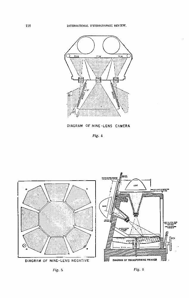
Because of the conditions mentioned in the preceding paragraph, multiple-lens cameras have been used by the Bureau since almost the beginning of its photogrammetric work. In the mid 1920s and early 1930s the Bureau used 3-lens, 4-lens, and 5-lens photography. However, none of these were too satisfactory and design of the nine-lens camera, illustrated in Figures 4, 5 and 6 , was undertaken in 1933. This camera was completed in 1937 and has been the principal mapping camera for coastal work since that date. T he nine-lens camera was designed specifically for mapping for nautical charting,, i.e ., to give w ide angular coverage for bridging water gaps and maximum definition of alongshore details. T he nine normal-angle lenses are arranged on a central mount with all axes parallel so that the nine separate images are exposed simultaneously on one piece of film. The wide coverage is obtained by combining a single vertical view from the central lens with oblique views taken through the other eight lenses which are arranged in an octagonal pattern abolit the central lens. T he fields of the eight outer lenses are deflected 38° from the central axis by stainless steel mirrors secured on a hollow stainless steel cone in front of the lenses. In making a print, the aerial negative is placed in a special transforming printer (Figure 6) and, by nine separate exposures on one piece of paper, the original relationship between central and, wing chambers is reconstructed and the nine images are recombined to form a single composite print which has the geometrical characteristics of a single-lens photograph with an angular coverage of 130° and a focal length of 21 centimeters. Prints are 35.4 inches square. Nine-lens photographs are usually taken at the same scale ratio at which the manuscript maps are to be compiled, i.e ., 1 :5,000, 1 :10,000, or 1 :20,000, with an end. lap between pictures along the flight of 60 % to 70 % depending upon terrain, and with a side lap between adjacent flights of 60 %. A single photograph at the scale ratio of1 :10,000 covers 5 .6 x 5.6 statute miles and at 1 :20,000 covers 11.2 x 11.2 statute miles. Photographs at scale 1 :20,000 are adequate for standard accuracy stereoscopic contouring at a contour interval of 15 ft., i .e ., the so called « C » factor is about 900. T he most outstanding service of this camera has been in the mapping of swampy, inaccessible areas along the southeast and Gulf coasts of the United States where control surveys are difficult and expensive, and in mapping remote areas of western and northern A laska where photographic weather is extremely scarce and where control surveys are difficult and expensive. In addition to its valuable service in these special areas, the nine-lens camera has, since 1937, solved the day to day problem of bridging water gaps and providing photographs of excellent quality for delineation of shoreline and alongshore details.
Single-Lens Cameras.
Smgle-lens cameras are used m conjunction with stereoscopic plotting instruments for mapping harbors and coastal areas, mostly in the continental U nited States, where the control and stereoscopic bridging problems are not so difficult and where the wide angular coverage of the nine-lens camera is not required ; single-lens cameras also are used almost exclusively for map and chart revision. A Fairchild « cartographic », or precision, roll-film camera wth a 6 -inch focal length Metrogon lens was used for most of this photography until 1954 when a W ild R C -5a, roll-film, precision camera with a 6 -inch focal length Aviogon lens was purchased. T he Aviogon lens is superior to the Metrogon because of its low distortion, its superior distribution of light over the entire field and its consequent higher resolution and better definition of photographic details. For these reasons it is rapidly replacing use of the Metrogon
DI AGRAM OF N I N E - L E N S C A M ER A
Fig. 4

lens for coastal mapping and for map and chart revision. Use of the Aviogon lens with its low distortion requires some modification of the stereoscopic plotting instruments and this is being accomplished as rapidly as possible. T h e Aviogon photographs can be used in Kelsh plotters by removing the distortion correction cams. Lenses, cones, and correction plates have been purchased for the two stereoplanigraphs and are being installed so that these instruments can be worked with either Metrogon or Aviogon photographs. Multiplex instruments in the Bureau are at present limited to the use of Metrogon photographs but a new printing head for the diapositive printer will be obtained soon so that the Aviogon photographs can also be used with those instruments.
A ir Photographic Laboratory.
T he A ir Photographic Laboratory processing, in common with aerial photography, accounts for a comparatively small part of the total cost of the completed map but is vital to the success of the subsequent operations inasmuch as the quality of the aerial negatives must be preserved and transferred to the several types of prints or photographs required for field surveys and for map compilation. T he Photo- grammetry Division maintains a small research group for the development and improvement of instruments and procedures, and for the maintenance of instruments. This group is responsible for technical direction of both the aerial photography and the laboratory photography, although the photographic laboratory is operated as a separate group and production is supervised by laboratory photographer. T he laboratory work includes the processing of single and nine-lens film, the printing of transformed and rectified nine-lens photographs and the printing of single-lens contact prints, ratio prints, rectified prints, and diapositives for use in Kelsh plotters, multiplex instruments, and stereoplanigraphs. T he laboratory is actually composed of 2 sections : a nine-lens section and a single-lens section. Nine-lens equipment includes equipment for developing and drying the large rolls of nine-lens film (23 inches by 200 ft.) ; two transforming printers (illustrated in figure 6), and a nine-lens rectifying camera. T he single-lens section includes standard roll-film developing and drying equipment, mul- tiple-lamp type contact printers equipped for variable contrast papers, a Saltzman ratio printer, a S E G IV type Zeiss rectifying camera, and a special vacuum holder for making contact diapositives for Kelsh plotters and stereoplanigraphs. T he last named printer is equipped with a point light source so that diapositives for the Kelsh plotters can be made by exposing through the film base. Future additions to the single-lens equipment will doubtless include a new S E G V type rectifying camera, and a Log-E electronic printer for making diapositives for the stereoplanigraphs and the Kelsh plotters, and for making contact prints.
Photogrammetric Field Surveys.
Photogrammetric field surveys are made prior to map compilation to provide control for the photogrammetric plots and for contouring; to clarify details on the aerial photographs, particularly the shoreline and alongshore features that cannot be adequately interpreted in the office without prior field examination ; and to obtain certain information that is not obtainable from the photographs alone, such as geographic names, road classifications, clearance of bridges over navigable waters, coast pilot data, selection of landmark objects for nautical charts, etc. M aps are then compiled from the survey data and the photographs. Field examination and correction of the maps after compilation is limited, and may be omitted entirely as explained in a subsequent paragraph. This practice of doing all or most of the field work prior

to compilation has been found from many years of experience to be the most economical procedure in mapping for nautical charts because of the fact that the shoreline and the alongshore features must be identified and clarified by ground examination before they can be correctly and completely compiled. There are some exceptions. In mapping A laska areas field work prior to compilation is often omitted entirely; preliminary manuscript maps are compiled for use of the hydrographic party which then does the photogrammetric field survey work in conjunction with the hydrography. The preliminary maps are entirely recompiled in final form after the close of the field season and are used in preparation of the hydrographic smooth sheet. This latter procedure is described separately in a subsequent paragraph.
Control Surveys.
Basic control surveys, i.e ., 1st and 2nd order triangulation and leveling, are usually completed by separate geodetic survey parties prior to mapping. The surveys which are described here are concerned mainly with supplemental triangulation, traverse, and leveling to provide horizontal and vertical control at the places required for the photogrammetric plot and for contouring. If any considerable extension or breakdown of the basic network is required, it is done using the methods of 2nd order triangulation or traverse and 2nd order leveling, and the stations are permanently monumented for future use. Additional unmonumented, lower accuracy, surveys are then made to provide control in designated places for the photogrammetric plot and for contouring. These latter surveys determine the geographic position and/or the elevation of picture points, i.e ., objects which are visible on the aerial photographs. Triangulation and traverse for this purpose are of about 3rd order accuracy except for the location of picture points very close to monumented stations where the picture point need be located only within an accuracy of one or two feet. Leveling for this purpose is done with sufficient accuracy to provide elevations of picture points correct within one-tenth of the contour interval. Favorite instruments for these control surveys are the W ild « T -2 » theodolite and the Zeiss « Opton » level. Trigonometric and barometric leveling are satisfactory and are often done for determining elevations of picture points for stereoscopic contouring at intervals of 50 feet or more.
Shoreline Inspection.
Shoreline inspection comprises a rather detailed examination of the shoreline (mean high-water line) and the alongshore features by the field inspector who compares the photographs with the ground and makes notations on the photographs that aid the office compiler in delineating these features accurately and completely on the manuscript maps. The mean high-water line is identified by the examination of debris and other marking on the beach, and is inked at intervals on the field photographs so that the compiler can delineate it with certainty. T he character of the foreshore is noted and the low-water line is indicated as nearly as practicable. Features outside the low-water line, such as rocks and other obstructions that are visible on the photographs, are examined and notes are made as to whether these are bare at high water or at some stage between high water and low water. Rocks and obstructions visible to the field inspector but not visible on the photographs are located if they are of immediate importance to charting or if their positions can be determined more readily by the field inspector than by the subsequent hydrographic survey. Elevations above the sounding datum are determined for rocks awash that are important to alongshore navigation. Blemishes or other colorations or marks on the photographs that might be misinterpreted by the compiler are either deleted or noted for investigation by

the hydrographer. O ther items covered by the field inspection include the measurement of clearances of bridges and of overhead cables crossing navigable waters, the investigation and recording of geographic names, the names and numbers of piers, and other information of importance to shipping that is not obtainable from the photographs alone.
Landmarks and Field Aids.Prominent objects of landmark value on charts and fixed aids to navigation
are described and identified on the aerial photographs. Landmark objects and fixed aids to navigation in harbor areas are usually located by triangulation for plotting on the larger-scale charts. They can be located with sufficient accuracy by the photogrammetric plot if the manuscript map is reduced one-half or more for application to the chart, and under this condition they may be located either by the photogrammetric plot or by ground surveys (triangulation) depending upon which method is the more convenient.
Inspection of Interior Areas.A similar but somewhat less detailed inspection is made of the area inland
from the coast to record the classifications of roads, to clarify the shapes and positions of buildings where they are not clearly visible on the photographs, to investigate and record geographic names, to clarify principal drainage if this is partially obscured on the photographs, and to obtain other needed information that cannot be obtained solely from the photographs.
Field Completion.A fter the compilation of a map, a limited field examination and correction
of inadequacies are usually needed regardless of the thoroughness of the précompilation field inspection. In most cases the coastal maps discussed here are used by hydrographic parties soon after they are compiled, whence the alongshore features and other information of importance to charts are field-examined and corrected if inadequacies are found. Consequently, field completion surveys by separate field completion units are limited largely to the interior (back from the shore) sections of topographic maps of coastal areas in the United States where the maps are to be published by other agencies as part of the « Topographic A tlas ». Because of the completeness of the précompilation field inspection, the field completion surveys are devoted for the most part to the examination and correction of contours compiled with stereoscopic plotting instruments, and to the mapping of cultural features built since the précompilation field inspection.
Map Compilation.T he office compilation of manuscript maps from the field survey data and
aerial photographs comprises four principal work phases, or steps: ( 1) laboratory photography for making the necessary prints from the aerial negatives ; (2) photogrammetric plotting, either radial plotting or stereoscopic instrument bridging, which spans or bridges between ground control stations to fix the position and orientation of each photograph, or model, prior to the delineation of details on the manuscript; (3) the delineation of contours and planimetric details either by means of stereoscopic instruments or graphic methods; and (4) map completion and printing. T he nine-lens and single-lens systems are rather different and are treated separately in describing these processes.

Nine-Lens System.
T he nine-lens system includes the following instruments and operations : ( 1) the aerial camera; (2) transforming printers for combining the nine separated negative areas into one composite photograph equivalent to a single lens photograph;(3) radial plotting to fix the orientation and position of each photograph, (4) rectification, and (5) manuscript delineation either with the Reading plotters or by graphic methods. If graphic methods are used, the rectification step is omitted.
Printing Nine-Lens Photographs.
Prints from nine-lens aerial negatives are made in a special transforming printer that combines the nine separate negatives into one composite photograph (figure 6 ). T w o printers are now available for this work; the second printer having been completed in 1954. A t least once a year, calibration photographs are taken of a nearly flat test area about 5 miles square, where some 120 targets of known position and elevation have been established, and from these calibration photographs a master templet is prepared for operation of the transforming printers. T he film is measured roughly prior to printing by matching camera mark positions in a darkroom and adjustments are made for film shrinkage or expansion. T he tangental distortion (error of assembly) of prints made for precise radial plotting and for contouring usually does not exceed one-tenth mm., and the prints are made on metal-mounted paper to avoid subsequent distortion due to differential changes of the paper.
Radial Plotting (Nine-Lens).
T he next step in nine-lens work is the radial plot for horizontal bridging, i.e . for establishing the horizontal position and orientation of each photograph. Ground control stations and selected pass points are identified on the office photographs and transferred stereoscopically to each overlapping photograph. A transparent vinylite templet is made for each photograph showing the principal point and rays to ground- control points and pass points. A ll vertical-control points are included as pass points if they are not on horizontal control stations. T he radial plot is laid with the transparent (vinylite) templets over a projection or grid on which the horizontal control points have been plotted. A fter adjusting the templets to fit ground control and to fit one another, the positions of pass points, indicated by the intersections of rays on the assembled templets, are drilled through the templets to the base proection or grid with a jeweler’s drill and a special jig which assures that the drill is held vertically. Horizontal-control points and pass points are named and numbered on the base sheets. Radial plots thus made with transformed but unrectified nine-lens photographs have an excellent strength of figure and, provide horizontal positions of pass points fully as accurate as bridging done with stereoscopic instruments. T his fact is due to :(1) the wide coverage per picture that permits a side-lap of 55 % to 60 % between flights so that azimuth lines between photo-centers are carried across the flights as well as along the flights; (2) the long air base between photographs (12 inches to14 inches) both along the flight and, across the flight so that angles of intersection of rays of pass points are about 90° ; (3) the fact that each point is intersected by from 4 to 8 rays, (4) tilts of the aerial camera from the vertical are usually significantly small as they average less than 30 minutes and rarely exceed 10 (although it is seldom required, if a photograph is tilted sufficiently to affect the plot, a preliminary plot is made to obtain rectification data, the photograph is rectified, a new templet is made, and the plot is readjusted and completed), and (5) the fact that the

photographs are prepared by using stereoscopic methods utilizing floating marks to identify control points and to transfer all points to adjoining photographs.
For radial plotting with nine-lens photographs one horizontal control station is required about every 3rd to 5th model along each alternate strip where the plot includes three or more parallel strips of photographs. For single flight lines, two stations, one on each side of the flight line, are needed at or near the ends of the flight and about every 8 th model along the flight with intermediate single stations about every 3rd to 4th model. Sufficient horizontal control is provided so that single strips or area blocks end on, or near, control and no part of the plot is cantilevered more than one or two models outward from the last control station.
Rectification (Nine-Lens).
Following the radial plot, each photograph that is to be used for compiling contours is rectified and brought to exact scale for delineation of the manuscript map on the Reading plotters. Rectification is performed by means of a special nine- lens rectifying camera and with reference to the radial-plot templets described above. T he radial templet is converted into a rectification templet by displacing each point radially outward from the center according to its elevation. The settings of the rectifying camera are adjusted in a prescribed manner so that the images of the photographic points are projected onto their respective templet positions. T he photograph is then exposed onto a second sheet of metal-mounted photographic paper. T he rectified print is negative in tone and the images are reversed in relative position. T his negative print is ordinarily used in the plotting instrument without much difficulty; if a positive is needed, the negative print is recopied with the rectifier in which all the adjustments are set for duplication, producing the customary type of positive photographic print.
Manuscript Delineation (Nine-Lens).
T w o Reading plotters are used for compiling manuscript maps from rectified nine-lens photographs. These instruments were designed for stereoscopic compilation from rectified aerial photographs of equal flying height and whose dimensions can be as much as 36 inches squares. A ny pair of rectified, distortion-free, aerial photographs or enlargements therefrom can be used satisfactorily with the plotters although they were designed primarily for use with the nine-lens photographs. H ence the plotters are said to be independent of the focal length of the aerial camera. Photographs taken with a metrogon lens, however, probably could not be used without first correcting the photographs for lens distortion. T he map scale produced by the instruments is normally the same as the datum scale of the photographs, and is usually controlled entirely by a photographic scale change during rectification. It is also possible to compile correctly at a scale somewhat smaller than that of the photographs. Complete theoretical correction is accomplished mechanically for the reduction of all planimetry to the datum scale for any elevation up to half the flying height. Elevation readings are shown on an indicator graduated in equally spaced divisions of one- thousandth of the original flying height of the aerial camera, and tenths of divisions can be estimated. T he relation of the indicated elevations to the original flying height is not changed by any photographic enlargement or reduction of the photographs.
W ith these instruments a work sheet is produced in pencil for each stereoscopic model; map details are then transferred from the work sheet to the manuscript

map. T he transfer of information from the work sheet to the manuscript map is controlled by the pass points located on the manuscript by the radial plot and on the work sheet by the plotting instruments.
T he Reading plotters are being used primarily for contouring areas in Alaska at contour intervals of 50 and 100 feet. T he tidal water surface provides vertical control for this contouring if it is visible in a model and additional elevations are determined, by trigonometric or barometric leveling, so that vertical bridging does not exceed one or two models. For contouring in the United States at intervals of 10 , 2 0 , and 40 feet vertical control is provided in each model. These plotters are also used for compilation of planimetric maps of rugged terrain.
Compilation of planimetric maps of low-lying or flatter coastal areas is done graphically using unrectified nine-lens prints. M ap details are studied and clarified under the stereoscope and additional pass points for control of delineation are located by radial intersection. Details are then traced from the photograph to the manuscript which is a sheet of transparent vinylite. M ap delineation is guided throughout by the field-inspection photographs and other field data described above under « field inspection ».
Photogrammetric Plots - Single-^Lens.V ery little radial plotting is done with single-lens photographs, and that
which is plotted is limited to small areas of flat terrain. T he horizontal bridging between ground control is ordinarily done with the stereoplanigraphs and multiplex instruments. This bridging usually starts with a controlled model and extends 6 to 8 models to close on one and preferably two control stations. T he horizontal bridging is then adjusted by straight line methods. Experiments are now being made with Kelsh model template plots and with a new method of adjusting stereoplanigraph bridging. These are described in subsequent paragraphs.
Contouring with the single-lens instruments is done at intervals of 10, 20 and 40 feet in the continental United States. For this work vertical control (a known elevation) is provided in each corner of each model, and additional elevations are usually provided along the level lines that must be run to obtain the control stations in the corners of models. V ertical bridging with the single-lens instruments has been limited to Alaska areas where 3 to 4 models are bridged vertically with the stereoplanigraph.
Adjustment of Stepeoplani graph Bridges.A graphic method of adjusting stereoplanigraph bridges developed by the
Army Service is being tried on coastal mapping as it permits much greater freedom in the placement of ground control with a consequent reduction in field survey costs. The control is so arranged that each strip to be adjusted includes a minimum of four horizontal control stations and about eight vertical control stations. T he horizontal control is arranged with one station near each end of the strip and with two distributed in between but no two of these stations need occur in the same model. Vertical control stations are arranged in pairs; one on each side of the flight line, with a pair at each end of the strip and with two or three pairs distributed in betw een; it is preferable that the stations of each pair occur in the same model but this is not essential. T he bridge is run on the stereoplanigraph by assuming a scale and orientation for the first model. T he x, y and z instrument coordinates are observed and

recorded for each pass point and each control point, and a graphic record of the points is also plotted on a long strip of tracing paper at the compilation scale. T he adjustment includes a system of arithmetic and graphic operations on the coordinate values of all the pass points and, control points in such a manner that the instrument coordinates of the ground control points are made to agree with the known field- determined values.
The adjustment consists of two major parts, the first of which is arithmetic and is accomplished by the use of the I.BJM . machines and the second is based on graphs. The first operation comprises a set of translations, rotations and scale- factor changes to correct for the assumed position, scale, bearings and, inclination of the first model, executed to fit the control near the ends of the strip. T he second or graphic operation is used to correct for the systematic, accumulative, instrumental errors which are known to be of the nature of smooth quadratic curves. T he graphic work is based on the failure of agreement of I.B .M . and geodetic coordinates of intermediate control as the arithmetic operations ensure agreement at the terminal points.
T he arithmetic transformation is computed at one time by the I.B .M . to provide x, y and z coordinates of all pass points and intermediate ground control stations transformed and, adjusted to agree with the ground coordinates of the terminal control stations. T he I.B .M . computations are made from a set of constant factors which are derived by desk calculator from analysis of the differences of coordinate values of control points near the ends of the strip.
T he graphic operations obtain corrections which are added to the computed values of the coordinates. These are applied with the realization that in a geometric bridge or chain of interconnected solid figures of this nature, unavoidable, repeated,, instrumental errors will cause the bridge to deviate gradually from its intended straight course in several w ays: ( 1) by increasing or decreasing in size or scale from photograph to photograph ; (2) by curving to the right or to the left ; (3 ) by bowing upward or downward; and (4) by twisting clockwise or counterclockwise. Moreover it is realized that these deviations occur as smooth curves.
In practice, therefore, curves are constructed on the tracing-paper record (laid on graph paper on a long table), connecting points whose ordinates represent the errors or differences between the computed and the geodetic coordinates of the intermediate control stations. Obviously, the curves pass through zero points in the terminal control areas. T he curves are actually constructed by the use of flexible plexiglass rods, or dowelling material. Six separate curves are constructed showing:
(1) Scale, or correction in x;
(2) Bearing, or correction in y;
(3) Elevation, or correction in z;
(4) Y-scale, a secondary element due to the x-scale error and affecting the y coordinates;
(5) Swing, a secondary element due to the horizontal bow and affecting the x-coordinates ;
(6) Tw ist, applied to the z-coordinates of all points not on the center line.
T he curves indicate corrections which are read off and applied to the I.B .M . coordinates of the pass points.

T he next phase of the procedure is to plot the pass points from their corrected, coordinates with a coordinatograph on the manuscript maps. T he delineation of details and contour lines is then done by multiplex or Kelsh plotters.
Model Templet Plots.
R adial plotting with stereo-model templets is being experimented with. T he models for a strip, or several strips, of photographs are set up, one by one, in the Kelsh plotter w ith approximate model horizontalization, and two templets showing the radial center and rays to pass points are made for each model. T ilt and relief displacements are automatically eliminated by the instrument and the function of the templet plot is to adjust the scale between ground control, whether for a strip or for a block of several strips. T he radial center may be any pass point and centers are selected so as to provide adequate intersections of rays to establish the map positions of the pass points. T his method will probably be slower and more costly than bridging with the stereoplanigraph or multiplex but may provide an adequate means of bridging when the stereoplanigraphs and multiplexes are not available. It may also prove to be advantageous for block plots since the scale adjustment is made across the flight lines as well as along the flights.
Compilation of Manuscript Maps.
A fter completion of the bridging, map compilation from single-lens photographs is done w ith the multiplex instruments or Kelsh plotters and occasionally with the stereoplanigraph. Compilation of planimetric maps in flatter terrain is also done bv graphic methods. In this case the stereoscopic instrument bridging provides the location on the manuscript of the center and pass points for each photograph. The compiler must then study the photograph under the stereoscope, locate additional pass points by radial plotting, and compile details by tracing from the photograph onto the manuscript which is usually a sheet of transparent vinylite. A ll manuscript delineation is guided by the field inspection photographs showing notations made by the field inspector. If manuscript delineation is done by multiplex or by Kelsh plotters, some of the shoreline details often are not sufficiently clear in the plotting instrument for accurate and complete delineation. In this case, the operator locates shoreline pass points, the manuscript is then taken off the plotting instrument, and the shoreline features are delineated by tracing directly from the field annotated photographs by adjusting to the shoreline pass points.
Control for Hydrography.
Most of the manuscript maps are used for the control of inshore hydrographic surveys soon after completion and special provision is made for this purpose. The procedure is as follows: (1) Points or features visible on the photographs are selected at intervals of about 3 inches along the shore (as measured on the manuscript maps) and are located as pass points which together with the principal point (radial center) of each photograph are shown on the manuscript maps ; (2) T he manuscript maps, or copies of them, and a special set of prints of the aerial photographs, are supplied to the hydrographic party. These photographic prints are ratio or rectified prints at the same scale as the manuscripts and the pass points mentioned in item 1 above are marked on them. (3) T he hydrographic party selects the alongshore objects that are to be used for hydrographic signals and identifies all such objects on the photographs by ground inspection. A selected object may be a pass point mentioned above, or

any other alongshore object suitable to the hydrographic party. (4) Each object selected and identified as a hydrographic signal is then located on the manuscript map. If this object happens to be one of the pass points the position is already provided; otherwise, the position is determined either by (a) holding the photograph to the adjacent pass points on the manuscript and tracing the signal position or (b) by locating the signal position by radial intersections. M ethod (a) is acceptable where the signal is at the same elevation as the adjacent pass points. Otherwise, method (b) is used. T h e hydrographic signals thus located on the manuscript map are then transferred to the hydrographic work sheet or boat sheet together with shoreline and alongshore details. T he photogrammetric manuscript is at the same scale as the inshore hydrographic sheet and the transfer of signals is readily accomplished by placing the photogrammetric manuscript over the hydrographic sheet, holding to projection lines, and pricking the signal positions through with a fine needle. Separate reverse prints of the photogrammetric manuscripts made with a slow drying ink are usually provided to facilitate the transfer of the shoreline and alongshore details to the boat sheets.
Preliminary Manuscripts.
T he procedures outlined in preceding paragraphs require field work prior to compilation, whence a field party must work in the area usually one season in advance of hydrography. This is not economical nor feasible in some A laska areas where all field work has to be supported by major survey vessels. In these places a different procedure is used that permits all field work to be done in one field season. T he procedure is as follows. (1) Preliminary manuscript maps are compiled without benefit of prior field work for the location of picture points or for clarification of photographic details. T he photogrammetric plot for a map, or series of maps, is made without benefit of ground control. H ie geometry of the plot is held as rigidly as possible and the extent of the plot is limited so that the scale ratio and direction between points in the plot are reasonably correct and consistent throughout, although the exact scale is not known and the plot is not adjusted to geographic datum. Shoreline and alongshore features are compiled and the hydrographer is furnished with copies of the manuscripts and specially prepared photographs as outlined in the preceding paragraph. (2) The hydrographer selects, identifies, and locates hydrographic stations, and transfers the hydrographic stations and shoreline information to his work sheet exactly as outlined above with this exception : (a) either he must use each map (or series of maps in a specific radial plot area) as control on a local geographic datum without relation to adjacent areas or (b) he must determine the geographic positions of a few points on each map and by this means transfer the details from the map to their correct geographic positions on his work sheets or boat sheets. (3) The hydrographic party also locates picture points and inspects and clarifies photographic details, as described under « photogrammetric » field surveys », so that the maps can be entirely replotted and recompiled on correct geographic datum. (4) Each preliminary manuscript map is recompiled after the close of the field season using the same procedures for the photogrammetric plot and map delineation as described in preceding paragraphs. A ll of the hydrographic signals located during the field season are relocated on the final manuscript maps. (5) T he final manuscript maps are then used by the hydrographic party to plot the smooth inshore hydrographic sheets or records that indicate the correct positions of all soundings. T his procedure adds considerably to the office work of map compilation but conserves the time required for the field surveys.

Map Completion.
M ap completion includes a final office edit, or review, of the manuscript map, drafting or scribing for reproduction, and reproduction and printing of copy for filing in the Bureau and Archives. Each manuscript map is carefully verified for accuracy and completeness prior to its release by the compilation group. T he manuscript map is then ready for use for chart compilation, for hydrographic surveys, and for special field completion surveys when these are required. Revisions or corrections found necessary by the hydrographic survey, or field completion survey, are applied to the manuscript by the compilation group. Each manuscript map then goes to a review and drafting group for a final inspection and appraisal to insure its compliance with Bureau and National standards and for the preparation of copy for reproduction and printing.
Map Drafting and Printing.
A smooth copy of each manuscript map is prepared for reproduction and printing by drafting or by scribing on coated plastic (vimylite or mylar) sheeting. Techniques for scribing on coated plastics have developed rapidly in recent years and in 1954 the preparation of final map copy was converted almost entirely from pen and ink drafting to scribing. Scribing techniques still require considerable development as regards tools, the engraving coating for the plastic sheets, and methods of handling and processing but this method already has proved to be more economical and to produce better copy than the former pen and ink drafting procedures.
T he scribing of the manuscript maps for reproduction and printing is described here for convenience and for placing this operation in proper sequence. In actual practice, however, most of the scribing is done by the compilation groups during compilation of the manuscript maps and the scribing required after final inspection and review of the manuscripts is limited to correction of the original scribed copy. Each manuscript map is first compiled in pencil on transparent plastic sheeting; the pencilled manuscript is verified for completeness; the map details are transferred to coated plastic sheeting by a simple blue-line transfer process using light-sensitive, water-soluble dyes; and all line work is then scribed. Names and symbols (such as marsh, woodland, sand, etc.) are added by stick-up. T he scribed manuscript is next sent to reproduction and photographic copies are made for chart compilation, for hydrography, and for field completion surveys, etc. A fter final inspection and review the scribed manuscript is corrected as necessary by the drafting group and is then ready for final reproduction and printing. In some instances the scribing is done by tracing from the pencilled manuscript onto the scribing sheet on a light table. This latter procedure is not preferable but is necessary where the map copy from the stereoscopic instruments is produced in the form of a series of individual stereoscopic models rather than as a complete manuscript.
Printing and Filing.
A dry plate glass negative is made of each map and from this negative a one-color (black) lithographic print is pulled on cloth-backed paper. This printed copy, together with the map descriptive report, is permanently filed in the Bureau archives as a survey record of the particular area at the date of the last field examination. T he maps are not published. Instead, the glass negatives are used to print film positives which in turn are used to make ozalid prints for distribution to the public on request.

M ap and Chart Revision.
T he coastline is subject to continual change due both to natural causes and to the work of man. Consequently, chart revisions are often needed soon after completion of the basic mapping of an area. T he revision of land details on charts from aerial photographs is the subject of a separate paper by H . R . Brooks appearing elsewhere in this issue. T he subject is mentioned briefly here, however, for the sake of continuity. Considering this work in sequence, each of the new maps, illustrated in Figures 1 to 3 and described in the preceding paragraphs, is applied to the chart (or charts) of the area and the map is filed in the Bureau archives as a survey record of conditions at the date when it was made. Changes in the area are reported by chart users and are also detected by periodic aerial reconnaissance made for this purpose. A erial photographs of the changed area are taken as soon as possible after the changes occur, usually within six months. Corrections are made directly from these photographs to the chart drawings. In some cases a ground examination is necessary to clarify photographic details and, if the changes are so extensive as to require a photogrammetric plot, the base map is corrected first and the chart is corrected from the revised map. No attempt is made to keep the base maps up to date with changes in the same manner that charts are maintained. T he maps are revised after a period of some years when new maps are needed in conjunction with new inshore hydrographic surveys or if the accuracy of details on a chart begin to deteriorate because of numerous revisions.
M ap revision requires new aerial photography, field surveys, and a revision of the original map to produce a new map showing conditions at the time of the revision. This new map is then printed and filed in the manner stated above, and supersedes the original for charting purposes. T he elapsed time between the original mapping and map revision varies from 10 to 25 years in changeable areas depending on the extent and rate of changes.
Usually it is unnecessary to recompile completely the original base map as only part of the area will have changed and the unchanged details provide control for replotting and revision the changed areas. Aerial photography and field procedures for map revision are the same as previously described. T he office procedures are as follows; (1) A red-line print of the original map is made from the glass negative that is kept on file for this purpose. This print is made on transparent, low-distortion, plastic sheeting (vinylite or mylar). T he use of the glass negatives and low-distortion plastic sheeting preserves the accuracy of the original map. (2) T he photogrammetric plot is next made. This plot may be fixed on unchanged, well-defined, objects on the original map, or it may require additional ground control depending upon the extent of the changes. The plot may be made for one map or a series of maps.(3) M ap delineation is done graphically or by use of stereoscopic instruments depending on the type of terrain and extent of changes. N ew features are drawn in black on the red-line print mentioned in ( 1 ) above. This drawing then becomes the manuscript for the new map. T his manuscript thence shows unchanged details from the original in red and the new information in black. The new manuscript thus provides all information needed for the preparation of the final drawing by either drafting or scribing procedures. These procedures vary according to the extent of the revision : (a) the original glass negative may be corrected by painting out the changed areas and engraving the new details on the same negative, or (b) the changed areas may

be painted out on the original negative and a duplicate made from that negative on yellow-coated plastic sheeting. T he new information is then scribed on the plastic sheet as described under « M ap Drafting and Printing » ; or (c) the changed area may be painted out on the original glass negative and a positive photographic print made in black from that negative onto transparent vinylite sheeting. T he new information is then smooth-drafted by tracing from the manuscript and stick-up lettering or symbols applied to prepare the new map drawing for reproduction. In each case the unchanged parts of the map are preserved and are not redrawn or re-engraved.