photograph this sheet - defense technical … · photograph this sheet level u document...
TRANSCRIPT

PHOTOGRAPH THIS SHEET
LEVEL
U DOCUMENT IDENTIFICATION
I)IB~ON STATE Mrxfr xAppioved tot puhLic zejeaej
Distribution Unlimited
DISTRIBUTION STATEMENT
ACCESSION FOR
DTIC TAB ElVNANNOUNCWDE ELECTE
! JUSTIFICATION" -- AUG 258_ _ _ _ _ _ 0 I
DISTRIBUTION /AVAILABILITY CODES _,
DIST AVAIL AND/OR SPECIAL DATE ACCESSIONED
,,MUTIoN STAMP' 'UNANNOUNCED
83 08 11 002
DATE RECEIVED IN DTIC
PHOTOGRAPH THIS SHEET AND RETURN TO DTIC-DDA-2
FORM DOCUMENT PROCESSING SHEETDTIC OCT 79 70A
,At

V ." 4
IRICLASSIEE

~~ This document consirts of 112 pages,,ANo. _ _8_N . of 28 Copies, Series A.
COMPLETION,REPORTOPERATION HARDTACK, PHASE I IU. S. ATOMIC ENERGY COMMISSION CONTRACT AT(29-2)-460NEVADA TEST SITE 1958
MV" R S
AEC FACILITIES DIVISION
HOLMES & NARVER INC
CONSTRUCTORS
WN11 C1 TO EDrrI Pages 1.2,: "_'.:..t;\ . .. .. . .. N C " "IF E DA
,, ,. ., ., l '. . c. ',j ,.. , . ... , • -;'P/~~e 1 2.
' " . .... ........ . . _ ' . , i~ / " " N7 :
a'
DISTRIBUTION
DISTRIBUTION
COPY NO.Brig, Glen. A. D). Starbird, DirectorDivision of Military ApplicationU. S. Atomic Energy Commission1717 H Street NWWashington 25, D. C........................... ..................................... 1-2
K. F. Hertford, ManagerAlbuquerque OperationsU. S. Atomic Energy CommissionPost Office Box 6400Albuquerque, New Mexico...................................................... ................
James E. Reeves, Assistant ManagerOffice of Test OperationsU. S. Atom-ic Energy CommissionPost Office Box 5400Albuquerque, New Mexico...................................................... ...................... 4
R. G. Elliot, DirectorInformation DivisionU. S. Atomic Energy CommissionPost Office Box 5400
Albuquerque, New Mexico............................................................................ SW. W. Allaire, DirectorNevada Operations DivisionU. S. Atomic Energy CommssonPost Office Box 5400Albuquerque, New Mexico .............................-............................................ 6
L. W. Otoski, DirectorBudget DivisionU. S. Atomic Energy CommissionPost Office Box 5400Albuquerque, New Mexico ............................................................................ 7
C. C. Campbell, ManagerSandia Area OfficeU. S. Atomic Energy CommissionPost Office Box 5400Albuquerque, New Mexico ...................................................................... 8
E. C. Shute, ManagerSan Francisco Operations OfficeU. S. Atomic Energy Commission518 17th StreetOakland 12, California .............. ........................................................... 9-10
F. W. Hohner, Chief* Los Angeles Branch
U. S. Atomic Energy CommninsionPost Office Box 5450Los Angeles 55, California.......................................................................... 11
Page 3
'I ICEX lkU PAGN BLANK-NQT Y1LM~

DISTRIBUTION
DISTRIBUTION (Continued)
COPY NO.F. W. Hohner, Acting Chief
Las Vegas BranchU. S. Atomic Energy CommissionPost Office Box 2088Las V egas, N evada ............................................................................................................. 12-13
Dr. Edward Teller, DirectorLawrence Radiation LaboratoryPost Office Box 808Liverm ore, California ........................................................................................................... 14-15
Dr. N. E. Bradbury, DirectorLos Alamos Scientific LaboratoryPost Office Box 1663Los A lam os, N ew M exico ................................................................................................... 16-17
CommanderField CommandDefense Atomic Support AgencySandia BaseAlbuquerque, New M exico .................................................................................................. 18
Dr. J. P. Molnar, PresidentSandia CorporationSandia BasePost Office Box 5800Albuquerque, New M exico ................................................................................................... 19
R. L. Corsbie, ChiefCivil Effects Test OperationsDivision of Biology and MedicineU. S. Atomic Energy Comnmission1717 H Street NWW ashington 25, D . C . ........................................... .......................................... ........ 20
H. E. GrierEdgerton, Germeshausen & Grier, Inc.160 Brookline AvenueBoston 15, Massachusctts ........... .................................... 21
C. L. TylerReynolds Electrical & Engineering Co., Inc.Post Office Box 352Las Vegas, Nevada ................................................. 22-23
E. G. Bowen, DirectorAEC. Facilities DivisionHolmes & Narver, Inc.849 South BroadwayTos Angeles 14, California .............................................................................................. 24-28
Pago 4
FOREWORD
FOREWORD
This report covers the integrated activities of Holmes & Narver, Inc.,within the framework of Operation HARDTACK, Phase II, and includesEngineering and such field services as required by the United States AtomicEnergy Commission at its Nevada Test Site, Preparation of this docu-mentary is in accordance with the provisions of Mod-fication 74 to Con-tract AT(29-2)-20.
In addition to recording the participation of Holmes & Narver, Inc.,certain construction problems encountered by the CPFF Operating & Main-tenance Contractor and Lump Sum Contractors are discussed. Also a sum-mary of conclusions and recommendations directed toward the solution ofproblems experienced during this Operation is presented.
Operation HARDTACK, Phase II, was primarily a weapons develop-ment program, and the 37 events occurring within a six week period esta-blished a highpoint for ci accelerated test series. The successful completionof the Operation within this brief time allowance demonstrated the capa-bility and versatility of all participating and supporting agencies.
Page 5
N

TABLE OF CONTENTS
TABLE OF CONTENTSPAGE
D IS T R IB U T IO N .............................................................................................................. 3
F O R E W O R D 5................................................................................................................................ 5
CHAPTER ONECHAPTER I. GENERAL
Section 1. Participating Agencies ........... .......................................................................... 9
Section 2. N arrative Sum m ary ........................................................................................ 10
Section 3. Conclusions and Recommendations ............................................................ 16
CHAPTER TWO
CHAPTER II. ENGINEERING AND CONSTRUCTION
Section 1. Los Angeles Office Engineering ................................................................ 17
Section 2. Field Engineering ...................... ..................................................................... 26
Section 3. C om m unications ............................................................................................. 34
Section 4. C onstruction ................................................................................................... 36
Scction 5. T est Facilities .................................................................................................. 43
CHAPTER THREE i
CHAPTER III. ADMINISTRATIONSection 1. M anagem ent ................................................................................................... 72
Section 2. A ccounting ..................................................................................................... 79
Section 3. E stim ating ...................................................................................................... 81
Section 4. W ork O rders .. .............................................................................................. 82
Section 5. Personnel & Security ..................................................................................... 85
LIST OF ILLUSTRATIONSFIGURE PAGE
1. Head Towers at Stations U-3m, U-3n, and U-3q (left to right)Drill Rig Over Station U-3p .................................................... 13
2. General View of Tunnel U-12e Portal Arch ........................................................ 153. H&N Triangulation Survey Party ............................................................................ 29
4. Head Tower - Station U-3p - 100% Complete ................... . ........ 37
5. Steel Supports in No. 1 Alcove - Side Drift IJ-12b.03 .......................... 39
6. Steel Supports in Side D rift U-12e.05 ...................................................................... 407. Zero Station Index .................. ................................................................................. 42
8. Station T-3t - 90% Complete ............................................ 449. Station T-F1 - 100% Complete ......................................... 46
Page 6 3
Wi
TABLE OF CONTENTS
LIST OF ILLUSTRATIONS (Continued)FIGURE PAGE10. General View of Station T-F1 and Stations 522.01 through 522,10 ....................... 48
11. Stations 523.01, .02 and .03 - 100% Complete ................................ 4912. Tower Station T-7c and Base Structure Station 7-313 ........................................... 50
13. Stations 701.01 (right) and 702.02 (left) - .................................... 51
14. Stations 700, 701 and 702 - Area 7 .................................................................... 5215. Station T-8c Showing Power Cable Trench from
T ransform er to T ower ......................................................................... ...... . ...... 5316. Station B-9a Showi.,g New Concrete Pad and Wall ................................................. 54
17. Station 904 Prior to Backfil ................................................................................... 55
18. Station S-9f . 100% Com plete ................................................................ 5619. Station T-9d Prior to Installation of Prefabricated Cab ...................... 57
20. Tunnel U-12b Showing Powei, Signal, andC oaxial C able Installation ...................................................................................... 58
21. Transition from Wire Mesh to Steel Supportsin Side D rift U -12b.04 ..................... . ............................................. 59
22, Wire Mesh Used to Support Roof in Side Drift U-12b.04 ........... ......... 60
23. Concrete Encasement for Blast Door in Side Drift U-12b.02 ............................... 6124, Tunnel U-12c - Looking from Station 1 00 Towards Portal ................ 62
25. Transition from Timber Sets to Steel Setsat Station 8 + 96 Tunnel U -12e ......................................................................... 63
26. Steel Sets at Station 12 - 17 Tunnel U-12e ......................................................... 6427. Portal of T unnel U -12f .............................................................................................. 65
28. Interior of Station 12-301 Showing Ductwork andE lectrical Supports ................................................................................................... 67
29. Station 12-301 Prior to Backfill ................................................................................ 67
3 0. S ta tion 12-302 .................................................................................................................. 68
3 1. S ta tion 12-303 .................................................................................................................. 69
32. General View of Area 12 Cam p .............................................................................. 71
33. General Site Plan - Nevada Test Site ......................................................................... 89
34. A rea 3 - Layout ............................................................................................. ...... 91
35. Area 5 - G eneral Layout .......................................................................................... 9336. Area 5 -Detail Layout - Sheet 1 of 2 ...................................... 95
37. Area 5. Detail Layout - Sheet 2 of 2 ................................. 97
38. A rea 7 - L ayout .......................................................................................................... 99
39. A rea 8 - L ayout .......................................................................................................... 10140. A rea 9 - L ayout .......................................................................................................... 103
41. Area 12 - Layout .................................................... 105
42. U -12b T unnel C om plex ............................................................................................... 107
43. U-12c and U-12f Tunnel Complexes ................................ ................................. 109* 44. U-12e Tunnel Complex ................................................ 111
Page 7

TABLE OF CONTENTS
LIST OF TABLESTABLE PAGE
1. Number of Event% by Area and Placement .......................................................... 10
2. Comparison of Construction, Lump Sum vs. CPFF ........................... 12
3. Engineering Activity Statistics, Los Angeles Office ............................................. 20
4. Final Drawings Issued by Field Office ........ ........................................................ 20
5. Drawings Issued by Los Angeles Office ..................................... 21
6. Summary of Lump Sum Contracts Awarded ........................................................ 21
7. Sieve Analysis of Aggregate ..................................................................................... 31
8. M ix Design for 1 Cubic Yard of Concrete ............................................................. 32
9. Weight and Volume of Concrete Mix ..................................... 32
10. Sum mary of Concrete Poured ................................................................................. 32
11. Cost Summary (12 Months Ending 31 October 1958) ...................................... 80
12. C ost E stim ates Prepared ............................................................................................ 82
LIST OF CHARTSCHART PAGE
1. Schedule of E vents ....... ............................................................................................. 11
2. Los Angeles Office Man Hours - Engineering & Estimating - fHARDTACK, Phase. II vs. PLUMBBOB ................................. 24
3. Total Man Hours - Nevada Test Site and Los Angeles OfficeHARDTACK, Phase II vs. PLUMBBOB ........................................................ 25
4. Organization Chart, Eniwetok Proving Ground andN evada T est Site ..................................................................................................... 73
5. Jobsite Organization Chart - Nevada Test Site .................................................... 75
6. Holmes & Narver Personnel at Nevada Test Site -HARDTACK, Phase II vs. PLUMBBOB .............................. 76
7. Holmes & Narver Personnel at Nevada Test Site(A verage per M onth) ............................................................................................. 77
8. Number of Work Orders Per Month, Nov. 57 to Dec. 58 ......................... 83
9. Number of Work Orders Per Month.HARDTACK, Phase II vs. PLUMBBOB .......................................................... 84
Page a

T'his mnaterial confainsi nformation affecting the CATRI ETOm c:~~t~f ;~i ~CHAPTER 1. SECTION Inatinndl deense of the United States within the
moa'ening of thu ospionag0 laws. Title 18, U.S.C.,Sees. 793 ard 794, Ore fransrnitior, or revelationof which in any manner to an unauthorized peson CHAPTER Iis prohib;ted by Idw , E E AGENERAL
SECTION IPARTICIPATING AGENCIES
AEC Atomic Energy CommissionAFCRC Air Force Cambridge Research Center
AFOAT-I Air Force Office of Atomic Testing
AFSWC Air Force Special Weapons Center
AFSWP Armed Forces Special Weapons Project
ARA Allied Research Associates
ARF Armour Research Foundation
ASI Aero-Neutronic Systems, Incorporated
ASRDL Army Signal Research and Development Laboratory
BRL Ballistic Research Laboratories
CETO Civil Effects Test Operations
CONARtC Continental Army Command
CWL Chemical Warfare Laboratory
DOD Department of Defense
EG&G Edgerton, Germeshausen and Grier, Incorporated
ERDL Engineer Research and Development Laboratories
FCWT Field Command Weapons Test
FSI Federal Services, Incorporated
He-N Holmes & Narver, Incorporated
LASL Los Alamos Scientific Laboratory
LML Lookout Mountain Laboratory
LRL Lawrence Radiation Laboratory (formerly UCRL)
NRL Naval Research Laboratory
OCDM Office of Civi, and Defense Mobilization
ORNL Oak Ridge National Laboratory
REECo Reynolds Electrical & Engineering Company, Incorporated
RW The Ramo-Wooldridge Corporation
SC Sandia Corporation
SRI Stanford Research Institute
USC&GS United States Coast & Geodetic Survey
USGS United States Geological Survey
WADC Wright Air Development Center
WES Waterways Experiment Station
WRAIR Walter Reed Army Irstitute of Research
Page 9
( --

CHAPTER I, SECTION 2
SECTION 2NARRATIVE SUMMARY
OPERATIONAL HISTORY H. McElroy, S cetary of Defense, to-day announced plans for concluding
Follo\,ing the completion of Operation programmed nuch,ar testing prior toPLUMBBOB in the Fa!l of 1957, advance plan- the suslpnSion of tests far one yearning was initiated by the AEC, fl Scientific starting October 31 proposed by Presi-Users, and various participating agencies for con. (lent Eisenhower. The 1958 test pro-ducting a series of weapons tests at NTS dur- gram, which has been in progress at theing the period 1958-60. Engineering design for Eniwetok Proving Ground and Johns-major test structures and facilities was scheduled ton Island in the Pacific, will concludeto be accomplished in the Los Angeles Office, with approximately 10 low.yield nuclearwhile design changes to comply with field con- detonations at the: Nevada Test Site.ditions, available equipment and material, andlate criteria changes requesifd by the partici- "The Nevada tests will e held duringpants would be accomplished at Jok-ite. The September and Octoer and will beschedule for these tests had been dc;ind by completed prior to October 31. Severalthe end of February 1958, as follows: of the test shots will be contained un-
e 9derground in tunnels which have beenNO. OF under construction for several months;
OPERATION PERIOD EVENTS the remainder will he fired fromballoons or towers. More than half of
MILLRACE Fall, 1958 11 the tests will be less than one kiloton;the highest. yield will be in the nominal
TRUMPET Spring, 1959 27 (20 kiloton) range. Certain informa-MILLRACE "A" Fall, 1959 9 tion of interest to seismologists will be
provided in advance of the underground
MILLRACE "B" Fall, 1960 4 detonations.The possibility of a moratorium on the "News media representatives will he
testing of nuclear weapons became apparent in invited to observe the Nevada detona-June 1958; therefore, several events were ad- tions."vanced from the TRUMPET schedule to MILL- Concurrent with this announcement, theRACE. AEC initiated a revised program for NTS, de-
On 29 August. the Office of Information, signated Operotion HARDTACK, Phase II.AEC/ALOO, released the following public The Schedule of Events, as published on 10announcement relative to the program of nu- September 1958, was based on a total of 20clear weapons testing at NTS: shots: 6 vertical holes, 4 balloons, 9 tunnels, and
I tower. The program was later revised and ex-"John A. McCone, Chairman of the panded to encompaso the executed schedule asAtomic Energy Commission, and Neil shown in Table 1.
Vertical
Area Tower Tunnel Balloon Surface Holes Total
3 4 6 10
5 1 2 3
7 1 8 9
8 3 39 1 1 5
12 7 7
Totals 10 7 11 3 6 37Table 1. NUMBER OF EVENTS BY AREA AND PLACEMENT.
Page 10
)i

CHAPTEt 1, SECTION 2
OTERO U-34 LASL
BERNALILLO U-34 LASL - C~-
MCRA 9-7b LASL
TA OS U-3 LA SL C9CL E
EDDY - -LAS L 4LUNA - U-3 m LASL -I
M ERCURY U-121.01 UCRL iSIERRA 8-70 LASL C A N CF 1
MAR~fvS - U-A -2.O 0 CR 4 - -V --
-1iD'AL GO -7I LASL HI I iI IQUAY T - C F.ASL C~j
WRANGELL B-F o IJCRL iI 1COLFAX U-0LAL!
TAMLPAS U-a~.02 UCRL-
NEPTUNE U -12C. 03 UCRL il I LL
I -FIi~i~~LEA B-7b LASLLOGAN U-124.02 UCRL ~li IRUSIVMORE 8 -9 IJ CRL
-'
MAAM 'e 94 UCAL~
ONevada TeT Site
00

CHAPTER I, SECTION 2
Due to the acceleration of design and con- as-built drawings, and data on utility installa-struction of test facilities as a result of the r. !w tions. This document proved of immense valueshot schtdule, it became necessary to transfer to participating groups in planning their opera-to the Field Office all unfinished design work tional programs.or work not vet under way. This required theassignment of'20 Los Angeles Office engineering LUMP SUM CONTRACTSporsonnol to the Field Office, including the The significant decrease in lump sum con-Chief Project Eagineer - Project Engineering, tracts awarded during Operation HARDTACK,who coordinated all design criteria released by Phase II, as compared with previous operationsthe participiiting agencies. Personnel with cx- at NTS, was due to the accelerated program.pricncc in previous operations were used to a With time the prime factor, and faced withgreat extent to provide a high level of engineer- continuous criteria revisions, it became necessarying skill in the shortest possible time. to rely more heavily on the CPFF Operating &
The first, test. of Operation HARDTACK, Maintenance Contractor for construction ser-Phase 11, was the Otcro event, detonated on Vic5.s12 September 1958 in Station U-3q. Six other Table 2 compares the total of Lump Sumevents took place during September. and CPFF construction during Operations
Throughout October, an accelerated test- PLUMBBOB and HARDTACK, Phase II.ing program waii placed in effect to completethe schedule of events by the end of month. HARDTACKFor exaniple, on 22 October four events were Contract PLUMBBOB Phase, IId4itonntd, and on 29 and 30 October three shotswere fired each day. The final shot of the series, Lump Sum $ 4,814,979.72 $ 281,624.61the Titania event, was detonated on a 25-footlower in Area 8 at 1235 hours, 30 October. CPFF 11,506,352.19 6,578,499.89Operation HIARDTACK. Phase 11, was officially Table 2. COMPARISON OFconcluded at 23.59 hours PST, 15 November 1958, CONSTRUCTION, LUMP SUM VS. CPFF.
HIGHLIGHTSDuring Operation PLUMBBOB, about 70%One of the salient features of Operation of construction was accomplished by the CPFF
HAIIDTACK, Phase 11, was the "crash" nature Construction Contractor and approximately 30%of the program, It embraced 37 events in a period by Lump Sum Contractors. However, duringof approximately one and one-half months. This Operation HARDTACK, Phase II, the percen-required concentrated effort and close coordi- tage of construction performed by CPFF Con-nation among tho participating Laboratories, struction Contractor increased to approximatelyScientific Users, government agencies, the Archi- 5tect-Engineer, and the Operating & Main-tenance Contractor to complete testing by 30 COMMUNICATIONSOctober. Another significant feature of thisOperation was the increased u9e of underground To achieve increased efficiency and im-detonations. The feasibility of deep under- proved operational results, H&N installed a Corn-ground placement as a weapons testing technique munications Engineering Group at NTS staffedwas demonstraterd by the Rainier event in with specialists in both radio and telephone.Operation PLUMBROB. In May 1958, H&N communications en-
A geological engineer and mining engineer gineers initiated a cable testing program andwere added to the H8N staff to provide tech- converted cable records to as-built drawings.nical assistance (luring the scheduled events. Although this program had not been completedThese two engineers made valuable contributions at the start of the Operation, sufficient cablein the design of tunnel workings and interprets- testing had been accomplished to aid the AEC,tion of geological conditions in the elaborate the Scientific Users, and the Construction Con-tunnel systems. tractors in meeting the cable requirements of
an accelerated test program, In addition to pro-Throughout the Operation. H:N was en- viding engineering design, the II&N Communi-
gagel in an unusually large amount of surveying cations Group provided inspection of technicalactivities. Of the 160 peak number of H&N facilities and coordinated the communicationspersonnel at NTS. 104 were assigned to the requirements among all participating agencies.Survey Section, and one-third of these were em-ployd i th tunel rogam.A radio coverage survey of off-sitv Rad-played in the tunnel program. Safe radio communications resulted in the instal-
The NTS Facilities Brochure, which was pre- lation of repeater stations at Angeles Peak, Whitepared at the completion of Operation PLUMB- Mountain, Highlend Peak and Rib Hill. Gen-BOIB, contained area maps, architectural draw- erally, these sites provided satisfactory communi-ings, data on scientific stations, indexes of cations, however, second harmonic radiation
Page 12

CHAPTER I, SECTION 2
from one of the transmitters at Rib Hill inter- Pascal Event in Operation PLUMBBOB, werefered with another installation at this site and requested by LASL (Stations U-3k, U-3m, U-3n,system lock-up between Rib Hill and Highland U-3p, and 0-3q). Three of these stations werp toPeak occurred under certain conditions. The be completed facilities including a 500-foot deepdesign of an automatic transfer and failure hole eased with 36-inch diameter steel pipe, aalarm system for use with stand-by equipment middle and top concrete plug, a steel head tower,at the repeater sites was initiated to reduce a winch system, and were to connect to existingmaintenance and improve operation reliability, diagnostic bunkers with signal and coaxial cables.However, the time limitation of the program The other two stations were to be only 500-footwould not permit completion of the project in cased holes.time for use during the Operation. An AEC contract was awarded to Casey &
A feasibility study of the VHF radio sys- Montgomery, Inc., Bakersfield, California, fortom, including 1) the determination of a con- the drilling and casing of the holes. Drillingsolidated repeater s~te capable of sirving all started 2 -Jun. 1958, enid the first hole was casedoperational areas of NTS, 2) an analysis of the and grouted by 13 June. The drilling of theNTS frequency plan, 3) a proposed new fre- second hole, Station U-3p, commenced on 14quency plan, 4) propagation calculations and 5) June and was prepared for easing by 18 June,field tests, resulted in the relocation of the con. Six 32-foot joints (192 feet) of casing were weld-solidated repeater site from Smoky Jr. to Smoky ed and run into the hole when considerableSr, Time limitations precluded the possibility material sloughed into the hole and the casingof obtaining the crystals necressary to implement became immovable, During the next eight days,the new frequency plan; however, five of the continuous efforts by the Contractor to free theeight VHF repeaters were relocated to Smoky casing were unsuccessful and the hole wasSr. and the signal strength to pertinent loca- abandoned on 26 June,tions in Area 12 was materially improved. It is To provide the User with five completedplanned to relocate the three remaining VHF 500-foot deep, 36-inch diameter hole., Stationrepeaters to Smoky Sr. upon completion of field U-3r was added to the initial contract end be-tests, using the new frequency plan. twen 27 June and 7 August, the four remaining
holes were drilled and cased without incident.AREA 3 TEST FACILITIES The Conlractor again moved his drill rig over
U-3p on 8 August to clean the hole below theThe Area 3 test facilities to he used dur- 192-foot level and set 34-inch casings for the
ing this Operation required extensive engineer- full depth of the hole. No serious problems wereing and construction services, Five underground encountered in redrilling the hole to the 500-test facilities, similar to those used for the foot level, but after 310 feet of 34-inch casing
STAA .-3m
(58-I6-2)
Figure No. 1. Head Towers at Stations U-3m, U-3n, and U-3q(Left to Right) Drill Rig Over Station U-3p
Page 13
".,.... ... ,

CHAPTER I, SECTION 2
had been placed, the casing was again immovable. Preliminary criteria furnished by LRL dur-On 18 August the Contractor was given permis- ing September and October 1957 for the develop-sion to abandon this hole and the contract was meat of a new tunnel site south of Tunnelclosed. U-12b included 1) a straight 4000-foot long
access tunnel with two tracks, 2) three branchLater, it was determined that the U-3p hole tunnels leading to shot chambers, 3) a partially
would be required and the Operating & Main- buried multi-plate arch-type diagnostic building,tenance Contractor provided through a subcon- 4) a generator shelter, 5) a trailer parking area,tract, the services to bail the hole and place 6) space for vehicle parking, 7) space for a fu-concrete in the annular void between the 34 ture diagnostic shelter, and 8) a Contractorand 36-inch casings. During bailing operations, work and storage area.the bucket became wedged between the 268 and275-foot level and it was necessary to cut the In February 1958, the Users revised plan-lifting cable, with the bucket still in place, and ning to include seven side drifts having twofill the hole with concrete to the 251 1-foot level, blast doors, two blast traps, drilling alcoves and
a hooked-end configuration for each drift.Head towers for Stations U-3n, U-3p, andU-3q were to be provided by the Operating & Construction of the portal by the OperatingMaintenance Contractor and required construc- & Maintenance Contractor was started on 17tion of two new head towers from sections of a March, and excavation of the main drift corn-Self-shot tower in stock and modification of the menced on 19 April 1958.existing tower at Station U.3.j When the firm The Laboratory had originally planned onrequirement was initiated for five 500-foot deep using Stations U-12e,02 and U-12e.05 for Opera-holes and one shallow hole for use in the Opera- tion MILLRACE, With the announcement oftion, it was necessary to construct four head Operation HARDTACK, Phase 11, constructiontowers from existing tower stock and move one of the main drift was terminated at the work-tower from a previously utilized facility, ing face, station 20 -I 34, in order to meet the
To provide additional testing faciJities established deadline.quickly for low yield detonations (luring the During the first week in September, LRLlast 15 days of the Operation, two 70-foot high was directed to perform a preliminary test in-and one 50-foot high timber towers were con- volving a 6-foot diameter, 500-foot long vacuumstructed for LASL, using stock telephone poles pipeline and several underground alcoves. Toand timber. In addition, a 25--foot high timber meet this requirement the Logan event was sub-tower was constructed for LRL as a vehicle for stituted for the Pike event and it was necessarya low yield event, to scale the pipeline down to 24 inches in dia-
meter by 165 feet long. The U-12e.02 drift wasdriven for approximately 650 feet with maxi-
AREA 12 TEST FACILITIES mum effort and GZ was established on 27
Plans by LRL for the development of ex- September. The Users moved in their equipmentisting Tunnel U-12b for use in Operation MILL- on 4 October, and the Logan event was detona-RACE included 1) the modification of the ted at the end of this drift on 15 October.diagnostic building, Station 12-300, 2) the con- The U-12e.05 drift for the Blanca eventstruction of two trailer parking areas, and 3) was driven to obtain the maximum overburdenthe excavation of four side drifts off the main possien t otec the main overomdrift for shot locations, each drift with a button- collapse as a result of the Logan event. In addi-book configuration leading to the shot chamber tion, steel sets were installed on 4-foot centersand with alcoves off the entrance for instruments for the first 500 feet of the drift.and equipment. Considerable damage occurred to the main
Shortly after the start of Operation HARD- tunnel as a result of the Logan event and it wasTACK, Phase 11, the requirement for the use necessary to excavate a new tunnel from stationof the U-12b.01 side drift was deleted. 17 + 94 to the portal of the U.12e.05 drift, and
The first test in the U-12b tunnel complex, relocate GZ at station 5 + 97.the Tamalpais event, was held in Station The construction of five safety test facfli-U-12b.02 on 8 October. While recovering film ties off the existing main access Tunnel U-12fafter the test, the accidental igniting of gases was requested by LRL in July 1958. Eachresulted in an explosion that caused consider- facility was to consist of a short drift with aable damage to the main drift and to the other hook at the end, a blast door, and a small alcovethree side drifts. Therefore, the Rushmore event for one instrument drill hole.scheduled for U-12b.03 was rescheduled to aballoon in Area 9, and much of the diagnostic The requirement for U-12f.05 was deletedeffort that was to be acquired from the Evans in August. The final configuration of the U-12fevent in U-12b,04 was sacrificed, complex follows:
Page 14
-,4f

CHAPTER I, SECTION 2
(t"8-1-18)
Figure No. 2. General View of Tunnel U-12e Portal Area
U-12f.01 155 feet at station 3 I- 70 holes from the site originally planned to a point.02 155 feet at station 4 + 30 above the U-12b.04 GZ. During the interim.03 311 feet at station 4 + 90 period between drilling completion and instru-.04 155 feet at station 5 + 30 mentation considerahle sloughing action resulted
from detonations in the immediate area, and itU-12f,03 and .04 side drifts wore abandoned was necessary to ream one of the holes to 121/
and relocated to surface test facilities in Area inches and redrill and clean the other three9, due to radioactive contamination caused by prior to lowering the instrumentation.the Mercury and Mars events.
Another safety test installation, Station AREA 14 (LASL TUNNEL AREA)U-12c.03, was excavated in the existing PLUMB-BOB Tunnel U-12c and consisted of a 6-foot In June 1958, LASL requested that AECwide by 7-foot high by 165-foot long side drift provide two horizontal tunnels and a diagnosticat station 1 + 00. building, 20x30 feet, with coax lines to serve
both tunnels. One of the tunnels was to haveTo provide the Sandia Corp. and the Stan- 1100 feet of vertical cover, and the other was
ford Research Institute facilities for pre and to have 900 feet of vertical cover. As a resultpostshot iaeasurements, five 834-inch diameter of a survey made by the United States Geo-vertical instrument holes were drilled from the logical Survey, only one proposed site fulfilledtop of the mesa in Area 12. The John S. Hage- the vertical cover requirements, Since this sitestad Drilling Co., Bakersfield, California, under. did not provide for future expansion, LASL de-an AEC lump sum contract, moved on the drill- cided to abandon tunnel plans for Area 14 anding site 4 August, and drilled and cased the undertook the consideration of other areas, in-first hole to a depth of 892 feet. Due to several eluding Skull Mountain, the east side of Sho-
* program changes during the drilling operations, shone Mountain, an area north of Area 14, andit was necessary to relocate the four remaining Forty Mile Canyon.
Page 15
N
CHAPTER I, SECTION 3
SECTION 3CONCLUSIONS AND RECOMMENDATIONS
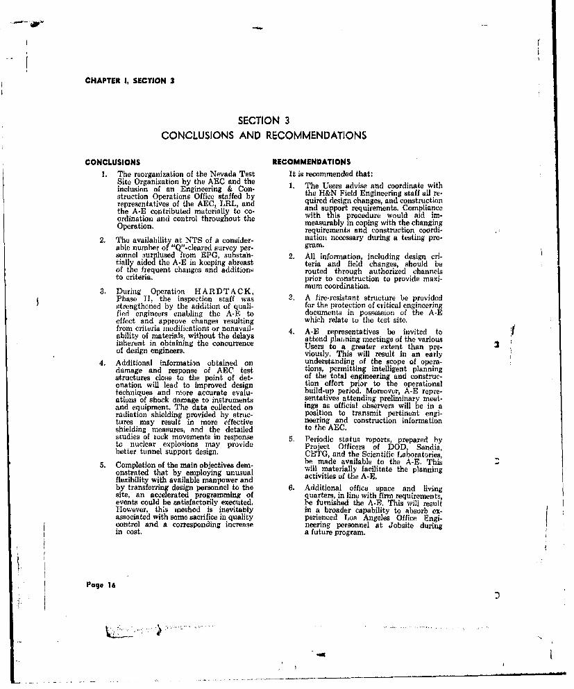
CONCLUSIONS RECOMMENDATIONS1, The reorganization of the Nevada Test It is recommended that:
Site Organization by the AEC and theinclusion of an Engineering & Con- 1. The Users advise and coordinate withstruction Operations Office staffed by the H&N Field Engineering staff all re-representatives of the AEC, LRL, and quired design changes, and constructionthe A-E contributed materially to co- and support requirements. Complianceordination and control throughout the with this procedure would aid im-Operation. measurably in coping with the changing
requirements and construction coordi-2. The availability at NTS of a consider- nation necessary during a testing pro-
able number of "Q".cleared survey per- gram.sonnel surplused from EPG, substan. 2. All information, including design cri-tially aided the A-E in keeping abreast teria and field changes, should beof the frequent changes and additions routed through authorized channelsto criteria, prior to construction to provide maxi-
3. During Operation HARDTACK, mum coordination.Phase I, the inspection staff was a, A fire-resistant structure be providedstrengthened by the addition of quali- for the protection of critical engineeringfied engineers enabling the A-E to documents in possession of the A-Eeffect and approve changes resulting which relate to the test site.from criteria modifications or nonavail- 4. A-E representatives be invited to Vability of materials, without the delays attend plaiining meetings of the variousinherent in obtaining the concurrence Users to a greater extent than pro-of design engineers. viously. This will result in an early
4. Additional information obtained on understanding of the scope of opera-damage and response of AEC test tions, permitting intelligent planningstructures close to the point of det- of the total engineering and construc-onation will lead to improved design tion effort prior to the operationaltechniques and more accurate evalu- build-up period. Moreover, A-E repre-ations of shock damage to instruments sentatives attending preliminary meet-and equipment. The data collected on ings as official observers will be in aradiation shielding provided by struc- position to transmit pertinent engi-tures may result in more effective neering and construction informationshielding measures, and the detailed to the AEC.studies of rock movements in response 5. Periodic status reports, prepared byto nuclear explosions may provide Project Officers of DOD, Sandia,better tunnel support design. CETG, and the Scientific Laboratories,
be made available to the A-E. This5. Completion of the main objectives dem- will materially facilitate the planning
onstrated that by employing unusual activities of the A-E.flexibility with available manpower andby transferring design personnel to the 6. Additional office space and livingsite, an accelerated programming of quarters, in line with firm requirements,events could be satisfactorily executed. be furnished the A-El. This will resultHowever, this method is inevitably in a broader capability to absorb ex-associated with some sacrifice in quality perienced Los Angeles Office Engi-control and a corresponding increase neering personnel at Jobsite duringin cost. a future program,
Page 16
CHAPTER ii, SECTION I
CHAPTER IIENGINEERING AND CONSTRUCTION
SECTION ILOS ANGELES OFFICE ENGINEERING
ORGANIZATION AND RESPONSIBILITIES Electrical, Mechanical, Structural, Checking,Specifications, and Coordination Sections; con-
Engineering functions in the Los Angeles sisting of engineers, designers, and draftsmenOffice were under the direction of the Engineer- functioning under the direct supervision of See-ing Manager who was responsible for the prep- tien Chiefs.aration, review, and issuance of engineeringdesign for test structures and facilities developed An Assistant Project Engineer was assignedfrom criteria received from the AEC and various the position of Assistant Coordinator, Engi-Scientific Users, The supervisory staff of the neering & Construction Operations, on the TestEngineering Manager consisted primarily of the Manager's staff. This component of the TestChief Project Engineers for Project Engineering, Organization reviewed and coordinated construe-Blast Study, Communications, and the Chief tion and support requirements of all partici-Production Engineer. pating Users, Agencies, and AEC.
The Chief Project Engineer, Project Engi- DESIGN AND CRITERIA DEVELOPMENTneering was responsihle for 1) the processingof AEC and User criteria, 2) scheduling of de- The following discussions concern only thesign completion to permit sufficient construc- stations involving major engineering design. Thetion time to meet User occupancy dates, and description of other scientific stations for which3) checking to ensure that design conformed engineering was performed in the Los Angelesto User criteria. Project Engineering maintained Office is contained in Chapter II, Section 5.close liaison with the Scientific Users in orderto incorporate the latest design changes on Stations U-3k, U-3m, U3n, U.3p, and U.3qdrawings prepared for test structures and facili- LASL requested that design be accom-ties. This group also maintained liaison with plished to support several underground safetythe Resident Engineer on design responsibili- tests. A proposed layout was received for fiveties, and forwarded advance engineering draw- zero points in Area 3 that were located 200 feetings for procurement items requiring long lead apart and 1000 feet from Station 3-300. Road,times, power, signal, and coax requirements were to
The Chief Project Engineer, Communica- remain basically the same as for the Area 3tion, was responsible for the design of all signal, stations constructed for the Pascal event duringcommunication, and radio requirements at NTS Operation PLUMBBOB and Project 58-NTS.and for the maintenance of all records concern- Each zero point was to consist of theing telephone and signal cables installed in the following.forward area. 1. A 500-foot deep hole, cased with
The Chief Project Engineer, Blast Study, 36-inch nominal diameter steel casing,assisted by design specialists, studied the to the following specifications:effects of nuclear blasts on existing AEC struc-tures, developed more reliable information on a. Plugged at the bottom and water-quantities and velocities of rock broken from tight.tunnel walls, and recorded the deflection and b. Straight within a tolerance of ° .
damage of tunnel linings exposed to nuclear b. Soexplosions. c. Vertical within ±5.
The Chief Production Engineer was re- d. Clear ID of at least 34 inchessponsible for the production of all engineering and tested with a mandrel 35 feetdesign and drafting on a controlled schedule. long with 32 -inch minimumHe provided overall supervision for the Civil, OD.
Page 17

CHAPTER II, SECTION I
e. Clear ID of at least 341/2 inches 500-foot Steel Shot Towersfor top 10 feet and tested with amandrel 10 feet long with 34-inch H&N was requested by LASL to developminimum OD. design drawings and specifications for three
500-foot structures, utilizing five 300-foot towersf. Replace drilling mud around the stockpiled at NTS, It was requested that the
pipe with concrete for the entire following, plus any additional items required500-foot length. for modification, be authorized for procure-
ment:2. A 5-foot steel-encased concrete plug
placed near the 250-foot level with 1. Elevator cabs and controls.side slots for coaxial and hoist cablesand a central collimation hole. Con- 2. Elevator guide rails and connections.crete would not be placed in the plug S. Elevator sheaves and sheave compo-until the line-of-sight had been checkedand the exact position of the colli-mation hole had been established. 4. All standard tower electrical compo-
3. A second concrete plug, consisting of nents.a 28-foot long steel cylinder filled with 5. New permanent guys at the 500-footfour 5-foot long concrete cylinders, was level.to be placed at the top of the hole.A separate User-furnished canister con- 6. New temporary guys at the 400-footnected underneath the provided com- level.partment. 7. New guy connector plates at the 300
Jobsite Engineering was requested to ac- and 400-foot levels.complish the design for the stations, with theLos Angeles Office providing assistance as re- 8, Additional guy anchor beams (eightquired. Prior to submitting drawings for User per tower).approval, Jobsite was requested to furnish 9. New cabie for existing elevator hoists.copies to the Los Angeles Office for checkingand approval. Drawings were completed and forwarded to
the User. Approval was received with the nota-The head tower, which was to have a ver- tion that the drawings were to be filed, since
tical clearance of 621h feet, was redesigned as the use of 500-foot towers in the immediatea 75-foot tower with a sheave shelter. The sys- future was improbable.tem of winches and hoists went through fourmajor revisions; however, the final design re- Tunnel Designquirements specified two winches on the sameside of the tower with two sets of sheaves, one During late September 1957, H&N was re-above the other, and a monorail hoist. quested to provide LRL survey support to
establish the location of a portal and groundSignal and coax requirements consisted of zeros for a proposed tunnel, and to determine
one 16-pair signal cable connected to Station the profiles of the ground surface directly over3-300, one 26-pair signal cable connected to the tunnel centerline. The outline of the tunnelStation 3-354, one 6-pair telephone cable con- concept was as follows.nected to Station 3-24, nine runs of RG 18/1Tcoaxial cable connected to Station 3-300, and 1. The main tunnel was to be arsproxi-two runs of RG 18/U connected to Station mately 3200 feet in length with three3-300 from each of the six test sites through branch tunnels leading to shot cham-a common splice pit. bers. From the portal to the last branch,
the main tunnel was to be of sufficientDuring the month of April specifications width to permit two tracks, one for
for the drilling and casing of the five 500-foot the User and one for the tunnel con-holes were prepared in the H&N Los Angeles tractor. It was suggested that thisOffice, The Invitations to Bid on these holes could be accomplished by driving awere distributed on 25 April, tunnel 10 feet wide and installing
double tracks, or driving a tunnelSeven bids were received and Casey & seven feet wide and installing a singleMontgomery, Inc., Bakersfield, California, was track with frequent turn-out sectionsthe low bidder with a total price of $128,850 for passing.for the required work. Contract AT(29-2)-706was awarded to Casey & Montgomery, Inc., on 2. No special requirement was stipulated15 May 1958 and the Notice to Proceed was for a straight tunnel, other than easeissued, of construction.
Page 18
d 3

CHAPTER II, SECTION 1
3. Ventilation, coax, power, signal, and A conference was held at NTS on 7 Marchblast doors were to be similar to those with representatives of LRL to discuss the de-required for PLUMBBOB Station sign of blast doors for the various tunnel experi-U-12b. ments. Due to the special requirements for this
type of experiment, the complete design was to4. The requirements for the development be reviewed. Special consideration was to be
of a portal area were to be similar to given to the development of a gasket capable ofthe U-12b portal and consisted of containing gases at several hundred pounds perestablishing a portal floor elevation of square inch for several hours.6105 feet and developing an area atthat point for: Additional tunnel criteria were received from
the User in March indicating that the main tun-
a. A partially buried 24x80-foot Arm- nel was to be 4000 feet in length with sevenco multiplate arch-type diagnostic side drifts. Preliminary drawings were submittedbuilding. for approval during March and April, and tunnel
drawings prepared in the Los Angeles Officeb. A shelter for one to six generators were transferred to the Field Office to enable
which were to be remote from the the engineering designs to keep abreast ofportal and diagnostics shelter be- User's construction requirements.cause of the noise factor.
c. A scientific trailer parking space Station 12-301for four van-type trailers with Design criteria were received for a LRLstandard trailer outlets, diagnostic building to be located at the portal
of Tunnel U-12e. It was suggested that an Armcod. Sufficient area for approximately multiplate arch-type structure set into an er-
four typical NTS Brockhouses. bankmcnt would economically fulfill the require-
5. In addition, the following items could meants. The instrument room was to be air con-
be located on tailings or areas to be de- ditioned and insulated to maintain a tempera-veloped later than the required date ture range of 70 to 851F necessary for the satis-
eopthed p n pfactory operation of the electronic equipmentfor the prececding portal area:, inside the room.
a. Sufficient parking space for ap- Preliminary drawings were submitted to LRLproximately 20 vehicles, exclusive for comments and approval in March 1958. Dur-of Contractor requirements. ing April and May, H&N received User-re-
b. A future diagnostics shelter similar quested changes and in June the field staffto the first one, hut located on was notified to proceed with site preparation
the opposite side of the portal, and construction of the foundations.
c. Sanitary facilities. Vertical Instrument Holesd. Contractor work and storage areas. Specifications and contract drawings were
prepared in June 1958 for the drilling of liveThe tentative date for User occupancy of 8%-inch diameter vertical instrument holes
the first side drift and shot chamber was set at from the top of the mesa in Area 12. These1 April 1958. The main tunnel was designated holes were for pre and postshot measurementsas Station U-12e. being made by the Sandia Corp, and the Stan-
ford Research Institute. Holes No. 1 and 2 wereThe AaC disapproved construction of the to be uncased holes 1150 feet deep, and Holes
new tunnel facility on 23 October 1957, and sub- No. 3 and 4 were to be uncased holes 800 andsequently engineering design was discontinued. 600 feet deep, respectively. These four holesHowever, on 13 February 1958, H&N was rn- 60fetdprscivl.Tseorhlsfowrmed ta al woburk n 58, conne n ih t e- were to be located 90 degrees apart on a 25-footformed that all work in connection with the do. radius around Station U-12e.05 GZ. Hole No. 5sign of the tunnel would be resumed and that was to be a cased hole, 865 feet deep, locatedLRL was developing revised criteria which would 300 feet from Station U-12b.04 GZ.be available during the week of 17 February.Meanwhile, a LRL letter, dated 14 February, AEC Contract AT(29-2)-738, in thenotified H&N that planning at the Laboratory amount of $68,785 25 was awarded to the Johnindicated that Tunnel U-12e would be developed S. Hagestad Drilling Bo., Bakersfield, Calilonia.in accordance with the basic design prepared bythe A-E, with certain modifications. Firm cri- htension of Power. Roads, and Signal Linesteria for the side drifts were not developed at to Area 11this time, but the general concept was to have t Atwo blast doors, two blast traps, drilling alcoves, In view of the proposed activities in Areaand a hooked-end configuration for each drift. 12, AEC authorized H&N to proceed with the
Page 19
' .. _ _ _ II

CHAPTER Ii, SECTION 1
development of engineering design, surveys, SPECIAL STUDIESdrawings, and specificadlons based upon the fol-lowing criteria: High Pressure Vessels
I., Extend the NTS power distributionlines into Area 12, investigating the gi&N performed a comprehensive investi-advisability of burying the transmis- gation and preparod cost studies for LRL tosion line to avoid possible blast damage. determine the means and feasibility of recovering
i lspecial nuclear materials from safety detona-2. Extend the forward area primary road tions at NTS. Two types of facilities were
from Area 2 to the existing surfaced considered; each included a steel containmentasphalt road at the base of the mesa, sphere complete with ventilation, a recoverySince this was only a temporary access system, and refrigeration for maintaining iceroad into Area 12, it was suggested within the sphere. The ice was intended to servethat a realignment might be necessary as an energy absorptive agent and as an aid into accommodate the heavy traffic and purging.to shorten the length of the road, The first type, a surface facility, was de-
3. Provide the signal cables into Area 12 signed to be located below an earth-covered,as required by the User Agencies. protective, concrete structure. The second type,
a tunnel facility, was designed to be located atThe power line, as constructed, was for tem- the end of an excavated hillside tunnel. Design
porary service to operate electrical mining equip- drawings and cost estimates were prepared, andment in the proposed tunnel area (Area 14). it was concluded that construction and operationH&N's PAC design had to be revised to take of the facility were feasible. The estimated costadvantage of this line. Preliminary proposals and was $231,973 for the tunnel facility, anddrawings were prepared for the extension of $277,102 for the surface facility.the primary road and power lines into Area 12;however, at the conclusion of the Operation, 1500-foot Lightweight Shot Towerapproval had not been received for construction.
Tables 3, 4, and 5 indicate the number of An investigation and study were made forengineering documents prepared during the LASL to determine the feasibility of construe-
period from 1 November 1957 through 31 October ting a lightweight 1500-foot, TV-type towercapable of supporting 5 to 10 tons at the top.
1958. The study was to include the determination ofmass and individual composition of the pro-
Engineering Orders Issued ........... 1184 posed tower material by 100-foot sections. TheShop Drawings Processed ....... 338 most suitable materials and types of members
were selected, and a framing ant support schemeAdvance Notices Issued ...................... 3 was determined to provide for an elevator faci-
lity. The mass and the composition of tower ma-Invitations to Bid ............................. 3 terials were itemized, and to establish the feasi-
Table 3. ENGINEERING ACTIVITY bility of the structure, the horizontal deflectionsSTATISTICS, LOS ANGELES OFFICE of the tower cab were predicted.
Schematic drawings and cost estimates wereprepared for the 1500-foot high lightweighttower. The cost for the facility, including founda-tions, tower, elevator, and control system, wasestimated to be $1,441,215, and the determina-
Type Orig. Rev. Total tion was made that the tower construction wasfeasible.
Civil 118 202 320
Electrical 123 144 267 LUMP SUM CONTRACTS
Mechanical 60 71 131 Plans and specifications were issued by
Structural 244 360 604 H&N at the request of the AEC, based on cri-teria submitted by the AEC and prospective
Communications 4 3 7 Users of the facilities to be constructed. Theplans included location drawings and complete
Totals 549 780 1329 details of the work. Where necessary to amendthe bid documents prior to bid opening date,Table 4. FINAL DRAWINGS addenda were issued to all interested parties,ISSUED BY FIELD OFFICE Amendments were not issued during the last
Page 20

CHAPTER II, SECTION 1
seven days of the bidding period. In all instances, Branch, invitation numbers, advertising dates,standard Government forms were used, and in- and bid opening dates were assigned by the Lasvitations were distributed to all interested con- Vegas Branch. Advance notices were issued bytractois to ensure competitive bidding, Final H&N to prospective bidders in selected cate-decision on awards was made by AEC after gories, according to the type of constructionconsulation and evaluation with H&N repre- work involved, These notices usually were mail-sentatives. ed 10 days before the advertising date to 75
or more contractors and invited interested partiesSince the lump sum contracts were execut- to request bid documents. All advance requestsed by the AEC, the entire program was con- were honored on bid release dates, and subse-ducted under specific authorization from the quent requests were honored as soon a theyChief, Las Vegas Branch. After approval of plans were received.and specifications by Users and the Las Vegas
PRELIMINARY FINAL
Orig. Rev. Total Og. Rev. Total
Civil 5 3 8 4 7 11
Electrical 53 4 57 14 10 24
Mechanical 25 6 31 13 8 21
Structural 83 14 97 36 18 54
Communications 141 56 197 16 7 23
Totals 307 83 390 83 50 133
Table 5. DRAWINGS ISSUED BY LOS ANGELES OFFICE
Contract Number AT(29-2)-706 AT(29-2)-738
Contract Subject 500-foot Deep Vertical InstrumentHoles Holes
Date of Invitation for Bid 4-25-58 7-8-58
Bid Opening Date 5-9-58 7-18-58
Date Awarded 5-15-58 7-24-58
Date of Notice to Proceed 5-19-58 8-5-58
Actual Starting Date 6-2-58 85-58
Completion Date 8-19-58 10-23-58
Original Contract Amount $128,850 $68,785.25
Cost of Change Orders and $46,845.05 $44,385.31Modifications
Actual Cost $171,087.05* $109,669.42**
Contractor Casey & Montgomery, John S. HagestadInc. Drilling Co.
The actual cost of Contract AT(29-2)-706 ** The actual cost of Contract AT(29-2)-738was $4,608 less than the total dollar was $3,501.14 less than the total dollarvalue of the contract as modified, because value of the contract as modified, becausethe actual quantities of work performed on the actual quantities of work performed oncertain items were less than the estimated certain items were less than the estimatedquantities as stated in the contract. quantities as stated in the contract.
Table 6. SUMMARY OF LUMP SUM CONTRACTS AWARDED
Page 21
JsJ

CHAPTER II, SECTION I
Bids were opened publicly by the Las Vegas transient response and resulting damage wereBranch with representation by H&N. Bid ab- provided by EG&G.stracts were prepared immediately with the H&N(Government) Estimates included. After con- The design of close-in ABC test structuressultation with H&N rgfericon must usually provide adequate strength to with-
sulttio wit H& rearding the qualification sadtebatidcdlasadsfiinof bidders and their bid proposals, LVB made stand the llast-induced loads and sufficient
recommendations to ALO for the contract shielding to protect against the extremely pene-
awards and subsequent Notices to Proceed. tratihg initial radiation resulting from nuicleardetonations. Near GZ such structures are usually
After awards were made, there were occa- underground and massive in construction. Also,sions when changes in criteria required plan prediction of the total rigid body response isand specification adjustments. Field Change important because of possible effects of high
Orders, prepared by H&N for AEC approval, accelerations on delicate instruments. Know-consisted of work descriptions, justifications, ledge of thu rigid-body response of structures ofdrawings, H&N estimates, contractor q-,- ,ons, this type, resulting from air blast loading, isand H&N recommendations. These we... ,ans- inadequate, and there is no sound theoreticalmitted through LVB to ALO as supporting basis for response prediction. For this reason,documents for formal contract modifications, approximate methods and empirical correlationAfter the Change Order had been approved by of experimental data are required to provide aABC, Notices to Proceed with the modified work basis for improved design of these structures andwere issued to the Contractor by V1VB. Field a more accurate evaluation of the probability ofChange Orders were incorporated into the con- shock damage to instruments and equipment.tract by formal contract modification by ABC,/ The primary cause for poor shielding inALO. structures is frequently the streaming of radia-
Enforcement of the provisions of the con- tion through the entrance-way where the thick-tracts was a function of H&N. The field force ness of material interposed is less than that ofat NTS made inspections of work in progress walls and roof. There is no known engineeringto ensure compliance with plans and specifics- method for satisfactorily calculating radiationtions and to make certifications necessary to intensities inside a structure, taking into accountsupport payments to contractors. Final accep- the shielding geometry.tance by H&N and payment of contractors by The data gathered during the OperationAEC constituted the close-out of the individual should result in more realistic predictions ofcontracts, damage and better tunnel lining design.
BLAST STUDY Program 34
H&N continued the program of developing The projects summarized below were plan-improved design criteria for AEC test tructures ned to provide much needed information onduring Operation HARDTACK, Phase I, as a shielding and response and, in addition, to makeparticipant in test projects. In accordance with observations and to collect data on blast andthe decision of the Test Manager, this partici- thermal damage to ABC test facilities. Twopation was included partly under the Civil Ef- reports to be published by the AEC Technicalfects Test Organization (CETC) and partly Information Service Extension will cover theunder the LRUJ shock effects test program, activities of this program's three projects: ITR
H&N participation with CETO was author- 1701, Physical Damage Survey of AEC Test
ized by the Test Manager in a meetieg with the Structures, and ITR 1723, Radiation Shielding
Director, CETO, on 15 September and formal- and Response Studies of AEC Test Structures,
ized by EWO 61008, Revision 4, dated 17 Sep-tember. Participation in nuclear tests conducted PROJECT 34.1in tunnels was approved orally by the Assistant The physical damage survey was conduct-Manager for Test Operations, ALO, on 3 Sep- ed wholly by H&N personnel. The project per-tember and confirmed by TWX. As a major sonnel observed and recorded blast and thermalparticipant in CETO activity, H&N provided a damage to a selected test site facility and todirector for Program 34, Nuclear Effects on AEC certain test structures to provide hater criteriaTest Structures, which was comprised of three for use in the design of AEC facilities. Thisrelated projects: Projects 34.1, 34.2, and 34.3. was a continuation of studies carried on inInstrumentation requirements were provided by Operations PLUMBI30B and HARD'1ACK,EG&G and BRL through arrangements with Phase I.CETO. Project 26.13, Evaluation of NuclearEffects on Tunnel Support Structures, was in- Observations were made of Station 7-313,cluded in LRL Program 26 due to its close a massive concrete basehouse at GZ. This base-relation to other effects projects in this program. house was exposed to extremely high pressuresMotion pictures and still photography to record during the Quay event. Observations were also
Pag. 22
-4D

CHAPTER II. SECTION I
made of seven wood-frame dwelling-type struc- Program 26turcs. They were studied for damage and totaldisplacement in the Mora, Lea, and Socorro ROET2.events. Project 26.13, Evaluation of Nuclear EffectsPROJECT 34.2 on Tunnel Support Structures was under the
direction of LRL. The purpose of this projectThe radiation instrumentation project had was to obtain more comprehensive information
as its purpose the study of shielding against on permanent displacements, changes in tunnelradiation provided by AEC test structures. The cross-sections, damage to tunnel linings, transientexperiment supplied information concerning ra- motions of rocks, velocities of fly rock, and tran-diation intensity as a function of shielding geo- sicnt deflections of linings; all leading to improv-metry. Four close-in concrete underground strut- ed damage-distance criteria and better design of
tures were utilized for this purpose: Stations tunnel linings to resist nuclear explosive effects,7-24, 7-53, 7.302.01, and 9-22-6001. Participa- Measurements consisted of:tion in Area 9 was in two events, Vesta and 1. Pro and post shot cross-sections-H&NRushmore; in Area 7 it was in three events,Morn, Lea, and Socorro. Approximately 250 film 2, Phototheodolite surveys to show chang.detectors and 25 chemical detectors were exposed es and damage - EG&Gin obtaining data. Support of this project byEG&G consisted of providing the radiation de- 3. Transient deflection measurements ontecters, reading them, and making a report of selected sets in U-12b.02, U-12b,04,the readings obtained, and U-12e,05 - H&NPROJECT 34.3 4. High-speed motion picture photography
of deflections of the same sets inThe blast instrumentation for this project U-12b.04 - EG&G
was carried out entirely by BRL personnel. The 5. High-speed motion picture photographypurpose of the project was to study the total of unlined tunnel section in U-12b04rigid body response of underground structures to demonstrate motions of rock andrelative to free-field response in the earth. Meas- fly rock velocities - EG&Gurements comprised 1) local blast overpressuremeasurements, 2) free-field accelerations of the These measurements were made during theadjacent ground, and 3) accelerations of the Tamalpais, Evans, Logan, and Blanca events,structure. The stations included were the tower The report on the data collected and evaluations,basehouse (Station 7-313) in the Quay went ITR 1714, Evaluation of Nuclear Effects onand underground telephone and transfo,mer Tunnel Support Structures, will be published byvaults (Stations 7-24 and 7-53) in the Mora, the Technical Information Service Extension,Lea, and Sorcorro events. Oak Ridge, Tennessee.
Page 23
4i

CHAPTER ii. SECTION 1
U U
0
LI
/n zZ
00 0
-4 N~ - - - -
Page 2

CHAPTER II, SECTION 1
0 L5
._ E, E 1,0
Ull r"
00
0 0 0 0 a 0 0 0 0
0 0 0 0 0 a 0 0 0 0
c0 %t 0 ( CD It0 0 0 It0
q I i
Page 25
.,- t
4 ~4..... , ,

C1APYER II, SECTION 2
SECTION 2FIELD ENGINEERING
GENERAL was increased to 21 with the transfer of severalLos Angeles Office engineering personnel, in-
During the interim period following Op- cluding the Chief Project Engineer. Theeration PLUMBBOB, the Field Engineering Field Engineering Section was delegated theorganization was enhanced by the addition of task of processing original criteria into finisheda Communications Section. This increased the construction drawings, Criteria were receivedField Engineering operating sections to four: from the various agencies and covered theDesign, Surveys, Field Engineering (Inspection), scientific structures required for User partici-and Communications. The supervisors of these pation in the Operation. With the exception ofvarious sections were under the direct super- the design for the U-12e tunnel complex, thevision of the Resident Engineer. U-12e diagnostic building, the fan house, scien-
The Field Engineering group was reduced tific power station, and the LRL Calibrationto 33 persons immediately following Operation Building, all items, including the U-12b tunnelPLUMBBOB. This force initially was occupied complex, were processed by the Field Engineer-with the development and recording of as-built ing Design Section.data and the preparation of the basic drawings Design problems requiring specialized at-for a Facilities Brochure and an Orientation tention were referred to the Los Angeles OfficeBrochure. for completion or review by the pertinent design
During the early part of 1958, plans for section, e. g. heating or ventilating problemsan elaborate tunnel complex for the MILL- were not processed in the field. Revisions toRACE-TRUMPET Operations began to take Los Angeles Office drawings were made by theform. One of these tunnel complexes was plan., Field Engineering Design Section, as required,ned around Tunnel Drift U-12b, remaining from to conform to field changes. Such revisionsOperation PLUMBBOB, and another tunnel .eceived Los Angeles Office comments or ap-complex, U-12e, was planned as a new facility. proval.The Los Angeles Office Engineering group as-sumed responsibility for engineering design of During the interim period, data for field-Tunnel U-12e, and the Field Engineering Group engineered facilities were received in writingaccomplished the engineering design for Tunnel which, in most instances, were supplementedU-12h. Augmenting this work, design require- by User-prepared criteria drawings. However,ments were imposed by several small User pro- as the tempo increased, particularly during thejects for interim studies. development of the U-12b tunnel complex, tele-
type and telephone instructions were receivedWhen Operation HARDTACK, Phase I, with greater frequency until the extremely
became a reality, the Field Engineering organ- rapid release of requirements and fluctuatingization immediately expanded to handle the criteria created severe problems in liaison anrapidly increasing work load. The four operating coordination.sections were strengthened both by new hiresand by the transfer of Lo.; Angeles Office per- The acceleration of all phases of the testsonnel to NTS on a temporary basis. A rapid program to meet the scheduled deadline madebuild-up to about 130 engineering personnel was it mandatory for participating User agenciesachieved to haludle the acceleiatrd development to establish resident offices at NTS. This be-of User requirements and to process the con- gan a period during which basic criteria werestantly changing criteria. This work force started transmitted orally from User representatives toto declinu after the peak of the Operation was the A-E, to be followed by written confirmation.reached. However, requirements fluctuated with such ra-
pidity that a recording of all criteria changesESIGN became impossible, and construction proceeded
on the basis of oral instructions. As a result,At the start of Operation HARDTACK, numerous design drawings were not completed
Phase 11, the Field Engineering Design Section until after the construction had been accom.was comprised of eight persons. This number plished.
Pago 26

CW-APTEft II, SECTION 2
Approximately 700 construction drawings long by 8-inch diameter line-of-sight hole to thewere completed by the Field Design Section GZ working point.and approved by on-site AEC and User rep-resontatives before issuance. Among these were The second design criteria, received duringdrawings for the following major scientific the middle part of March, proposed a 690-footfeatures: sida drift with 1) two blast doors, 2) one in-
strument alcove located near the branch pointU-12e tunnel complex for LRL off the main drift, 3) three intermediate drillingalcoves between the instrument alcove and theU-12f tunnel complex for LRL zero room, and 4) a 180 degree hook entering
U-12b tunnl complex for LRL the zero room. In this plan six holes would bedrilled from the zero room, through the drilling
One additional drift in Tunnel U-12e alcoves, to the instrument alcove.for LRL In late March, the distance from the side
Six underground stations in Area 3 drift to the zero location was increased by 10for LASL feet to a 700-foot total, and the size of the zero
Balloon inflation pad at the BJ "Y" room was enlarged to 18x15x12 feet high.
in Area 3 for Sandia Corp. Late in May, the dimensions of the groundzero room were increased to 20x15x12 feet high,
Three types of light, wood-frame, and the working point and six line-of-sight holestransite paneled buildings for CETO were relocated in the zero room, and a cole-
Ground zero stations comprising 50 manite shield was required around the workingand 70-foot high shot towers. point.
Foundation plans for a 50-foot steel After construction had started, it was foundshot tower in Area 9 that the location selected for the instrument
alcove was in an area badly fractured by the"Gravel Gertie" surface shot stations Rainier event during Operation PLUMHBOB.
Because re-entry into this alcove was absolutelyessential, it became necessary to "mirror-image"
Tunnel U-12b the entire drift from the tunnel entrance. ThisThe constant changing of basic criteria for placed the alcoves on the south side of the tun-
the U-12b tunnel complex had conziderable nel and a hook to the left in entering the zeroimpact on the design, field survey, construction room. As construction had advanced past theinspection, and completion date for this facility, first two curves it was necessary to modify the
entrance to the first intermediate alcove and toOriginally, the plans for this facility in- delete the blast trap,
cluded 1) the modification of the existing diag-nostic building (Station 12-300), 2) the con- During June and July, many details werenostc bildng Staion 2-30),2) he on- added and revised, such as the addition of sev-struction of two trailer parkin areas, and 3)the excavation of four side drifts off the main eral short length drill holes between the zerodrift for shot locations. Each of these four drifts room and the closure hook. In August, threewas to be constructed with a buttonhook con- of the major drill holes between the zero roomfiguration at the end leading to the shot cham- and the instrument alcove were deleted to enableber, and with alcoves off the entrance tunnel for completion of the facility prior to the 31 Oct-scientific instruments and drilling equipment. ober deadline.
During the design and construction of thefour side drifts, numerous changes were required. SURVEYSSide drift Station U-12b.04 is a typical example The H&N Survey Section at NTS was re-of development from transmittal of original sponsible for furnishing the H&N Design Sec-criteria and preliminary sketches to a final as- tions, AEC, all User organizations, and thebuilt facility. participating agencies with measured and cal-
culated survey information essential to the Op-The ieration. The work involved many types of sur-
mitted by LRL in February 1958, stipulated veys, and was accomplished by utilizing variousthe requirement for a single-track tunnel leading methods. The number of personnel in the Surveyto a 12x12x12-foot high GZ room located 505 Section varied from 32 to 104. Approximatelyfeet from the main U.12b drift, at a angle of 35% of the 104 nersons were employed iii the45 degrees. This tunnel had one blast door, a tunnels ,n three shifts.debris trap, and a 360 degree hook to the leftat the GZ chamber end. A 6-foot wide by 30-foot A strong framework of First and Secondlong alcove was to be located diagonally acros Order horizontal and vertical control was es-the drift at a point which provided a 40-foot tablished and maintained throughout the test
Page 27
N

* I fCHAPTER II, SECTION 2
site to provide precise points of known hori- monuments by using precalculated distances,zontal position and elevation. These points were bearings, and vertical angles. Upon completionmarked with brass caps set in concrete menu- of each hole and after necessary reaming wasments of sufficient size to insure stability. They completed, the extremities of each hole werewere placed to aid surveys during this and all again located horizontally and vertically, andfuture operations, and were established by the diameter measured to establish as-builtFirst and Second Order Triangulation and bench data. Six survey crews were assigned to drill-level procedures. Computations were based on hole activities, two crews to a shift, on a 24-houraccepted methods and adjustments were made basis. To verify the accuracy of work as drillingaccording to USCGS procedures. proceeded, daily logs were submitted by each
crew which were checked by the ComputingThe Design Sections at Jobsite and in the Section. Representing a continuing as-built
Los Angeles Office frequently requested the Sur- record of drilling operations, these logs provedvey Section to furnish location surveys, topo- invaluable during the Operation.graphic maps, cross-sections, and profiles offield terrain upon which to base engineering. Detailed as-built surveys were taken asThese surveys were used to establish site selec- construction proceeded, showing slab locations,tion, grade, orientation, drainage, and economical finished floor elevations, and blast door locations.construction. During the peak activity of the In addition, cross-sections were taken in allOperation, the Survey Section was called on tunnels, drifts, alcoves, and GZ rooms. In Driftto provide as-built information relative to align- U-12b.05 both pre-blast and post-blast crossment and overbreak in the tunnels as construc- sections were completed.tion progressed, so that late scientific require-ments could be designed to fit existing field con- Other activities included the location ofditions. These as-built tunnel surveys were also canisters, vertical drill holes in the floor ofused in the design of sandbag plugs to ensure Tunnel U-12b and vertical drill holes from thetunnel closure. The Survey Section set survey surface into the GZ chambers of U-12b.04,stakes to locate, orient, and establish grade for U-12c.03, U-12f.0l, .02, .03, and .04. To deter-the construction of all scientific facilities. After mine the minimum overburden above the pointconstruction was completed on many structures, of burst for each proposed underground event,as-built locations were determined. During the profiles were taken on the top and slope of theOperation, the Users requested numerous corn- mesa.puted positions, distances, angles, bearings, ele-vations, lines-of-sight, and special surveys. The Engineer Research and Development
Laboratories required an extensive survey to de-termine permanent ground movement resulting
Special Surveys from underground events. Precise surveys as setforth by the Project Officer for this program
Surveys were required to establish align- were started in early September 1958. Monu-ment and grade for excavation of all main tun- ments were established for these movementnels, side drifts, and alcoves in Tunnels U-12b, studies as follows:U-12c, U-12e, and U-12f. In addition, survey sup-port was furnished for the exploratory tunnel 1. Monuments were set in outcroppingsinto the Rainier event GZ. In Drifts U-12e.02 on the mesa slope to reflect move-and U-12e,05 the final configuration was a re- ments resulting from the undergroundsuit of continuing as-built surveys required when events in Tunnels U-12b and U-12e.construction variances and shot schedules dic-tated changes from the original design layouts. 2. Ten brass cap monuments were set inFor construction purposes, all surveys were concrete on top of the mesa to reflectof Third Order accuracy. At the peak of the the surface movement resulting from -'
Operation, six survey parties were Asigned to the Evans event. Horizontal positionsthe tunnel areas on a three-shift basis to furnish were determined by Second Order tri-complete survey support. angulation, and traverse procedures and
elevations were obtained by SecondH&N survey crews supported the drilling Order levels,
of the line-of-sight horizontal drill holes by es-tablishing location and aligning drill rods in 3. Forty-nine sets of 1'A -inch rebar men-all drifts. Drill holes in Tunnel U-12b required uments were driven in the walls, floor,a tolerance of 1/8 inch in 400 feet. To satisfy and back of Tunnels U-12b and U-12ethese requirements, Second Order bench marks to reflect movements within the tunnels.were established and additional traverses were Horizontal positions for these menu-run employing First Order procedures. Perma- ments were determined by Secondnent monuments were set throughout. Hole ex- Order traverse procedures and eleva-tremities and grades were located from these tions by Second Order levels.
Page 28
. . .-- _U : . . .
-~J
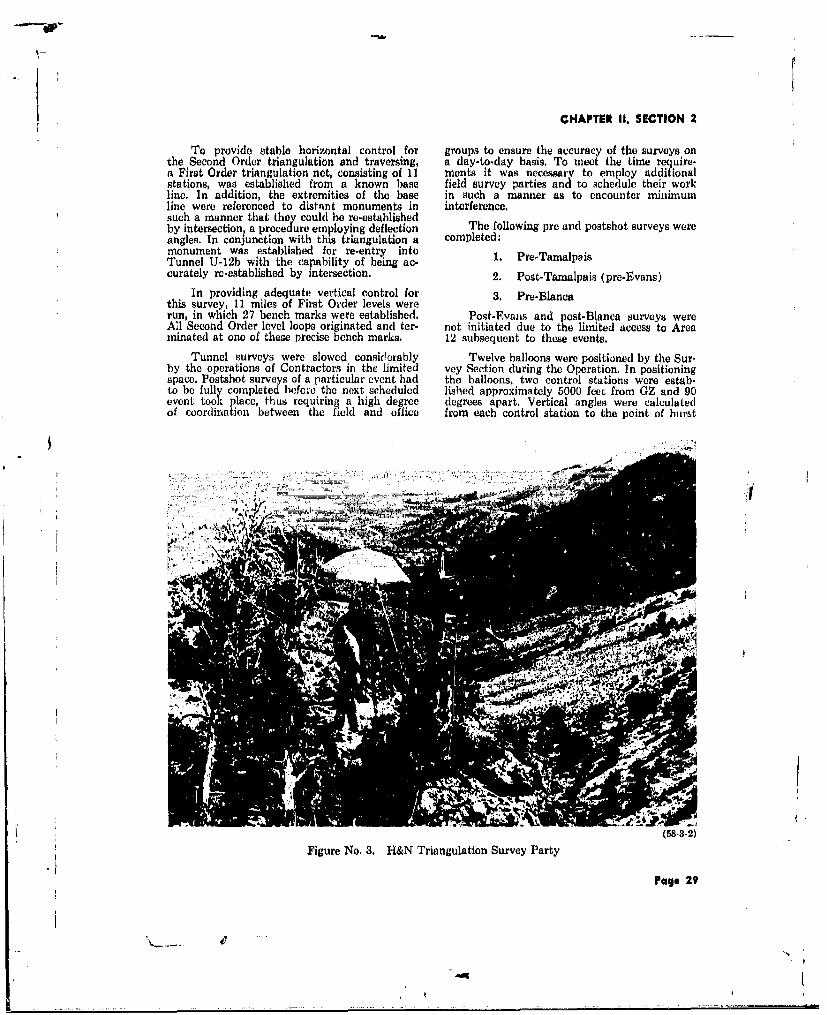
CHAPTER 1U, SECTION 2
To provide stable horizontal control for groups to ensure the accuracy of the surveys onthe Second Order triangulation and traversing, a day-to-day basis. To meet the time require.a First Order triangulation net, consisting of 11 ments it was necessary to employ additionalstations, was established from a known base field survey parties and to schedule their workline. In addition, the extremities of the base in such a manner as to encounter rinimumline were referenced to distant monuments in interference.such a manner that they could be re-establishedby intersection, a procedure employing deflection The following pre and postshot surveys wereangles. In conjunction with this triangulation a completed:monument was established for re-entry into 1. Pre-TamalpoisTunnel U-12b with the capability of being ac-curately re-established by intersection. 2. Post-Tamalpais (pre-Evans)
In providing adequate vertical control for 3. Pre-Blancathis survey, 11 miles of First Order levels wererun, in which 27 bench marks were established. Post-Evaiis and post-Blanca surveys wereAll Second Order level loops originated and ter- not initiated due to the limited access to Areaminated at one of these precise bench marks. 12 subsequent to these events.
Tunnel surveys were slowed considerably Twelve balloons were positioned by the Sur-by the operations of Contractors in the limited vey Section during the Operation, In positioningspace. Postshot surveys of a particular event had the balloons, two control stations were estab-to be fully completed befole the next scheduled lished approximately 5000 feet from GZ and 90event took place, thus requiring a high degree degrees apart, Vertical angles were calculatedof coordination between the field and office from each control station to the point of burst
Figure No. 3. H&N Triangulation Survey Party
Page 29
CHAPTER II, SECTION 2
in space. In positioning the balloon, the two con- and alignment was determined before and aftertrol stations were occupied, GZ was sighted, the this event.predetermined angles were set into the instru-ments, and the ascending balloon was moved Seven light wood-frame structures werelaterally and vertically until an accurate location located in Area 7 for participation in three sepa-on the two lines-of-sight was obtained. This rate events. Subsequent to each event, the struc-procedure was used throughout the Operation, tures were located relative to established ref-with one exception: the positioning of the Adams erence points to determine pre and postshotevent, in which the, device was armed while movements. In addition, 130 collimators werethe balloon was being positioned. Since existing staked in this Area.control stations were too close to use whilepositioning an armed balloon, it was necessary Topography by plane table was taken into establish control elsewhere. Two stations were Area 12 for the following projects:selected five to eight miles distant from GZ, 1. Parking areas - 4 acresand precise calculations were made to determine 2. Calibration range - 4 acresvertical angles. 3. Neptune crater - 4 acres
Extensive surveys were completed in Area 4. Blanca crater - 25 acres12 and throughout the NTS in support of gravity In Area 14, existing control was not avail-surveys conducted by the USGS. Gravity sta- able and extensive triangulation was requiredtions on five lines radiating from Station U-12.04 for satisfactory control. Due to the time elementGZ were located by Third Order traverse and a three-point fix was employed for control, andlevels on top of the mesa. Similarly, one line minimum profile lines were run at the proposedwas run down the slope of the mesa to the tunnel site.U-12e tunnel portal. For this survey, a total ofapproximately 90 gravity stations and 106 seis-mic shot holes were located, involving 2 miles of INSPECTIONtraverse and levels.
Throughout the NTS, random traverse lines During the period preceeding Operationwere run to establish gravity stations at inter- HARDTACK, Phase If, the Inspection Sectionvais of approximately one-half mile. A total of consisted of two Field Engineers. Their principal349 gravity stations were established, of which ac'dvities were in the Area 12 tunnels, which296 were located both horizontally and vertically, were in the excavation stage, and in Area 3 dur-Elevations only were determined on the remain- ing the drilling for the safety tests. The build- 8ing stations by Third Order procedures. Exten- up of Inspection personnel began in July, withsive calculations were involved, since the position the addition of a Chief Field Inspector, andof each station was required to be expressed in reached a maximum force of 13 in September,both Nevada State and geographic coordinates, including some temporary transfers from the Los
Angeles Office. The Mechanical and ElectricalFor fireball and documentary photography, Field Engineers were not assigned to specific
EG&G used a total of 25 camera stations. Each areas or stations, but were available to all areas,of these stations was required to be located in as directed by the Chief Field Inspector. Uponelevation and position for bearing and slant completion of the Operation, the Inspectionrange calculations on a true line-of-sight to the Section was reduced to six personnel; consis-point of burst for each event. EG&G also had ting of three Civil Engineers, one Mining Engi-19 illuminated photo towers requiring specific neer, one Electrical Engineer, and one Chieflocations on top of the mesa for ground-motion Clerk.studies in conjunction with the Evans event. The Inspection Section was responsible for
Miscellaneous Surveys the following functions: 3l. Engineering Supervision Sl Construc
In conjunction with the underground shots tion
in Area 3, it was necessary to stake out the loca-tion of air samplers as specified by the User in This section provided engineering in-the field. Tower T-3v presented a time problem spection of work performed by all con-with the movement of the Humboldt event from tractors involved ir the constructionFrenchman Flat to Area 3, complete with numer- of H&N-designed permanent facilitiesous DOD participating stations. or scientific test facilities. Liaison ser-
vice was furnished to all User agenciesFor the Hamilton event in Area 5, over 300 for both operational and construction
stations were staked, including biological pens, activities.film badge stakes, shauow-shield detector poles,fox-holes, and thermal gauges. The existing col- 2. Contract and Subcontract Field Ad-limator tubes at Station F-301 were uncovered, ministration
Page 30
8
" I

CHAPTER II, SECTION 2
a. With regard to lump sum con- 4. Support Engineering Services
tracts, field administration involv- a. The gathering of as-built infor-ed a review and an approval of the a e a ring os-utinfwr-Contractor's construction sched, maation during construction wasules and a periodic preparation of the responsibility of the Field En-data required to substantiate pay- gineers. These data were present.
This red to the Design Section to assistments to the Contractor. in the preparation of as-built draw-function also included the coordin-ation of Change Orders to existing ings.
contracts. b. Inspection personnel assisted inpromoting proper safety measures
b. Field administration provided the by making certain the Contractors'Operating & Maintenance Con- operations conformed to establish-tractor tiason with H&N Work ed safety rules and practices.Order and Estimating Sections indrafting work orders and modifi- c. Field Engineers provided liaisoncations, and in controlling "buck- among the H&N Jobsite Engineer-slips." Buck-slips were used as ing Design Section, the User fieldfield authorization for m i n o r personnel, and the Operating &changes requested by a User re- Maintenance Contractor's super-presentative, and were approved by visory personnel.H&N Field Engineers or the H&N Material TestsResident Engineer.
The majority of material tests consisted of
3. Reports and Photography concrete cylinder tests and in-place density testsfor soils. All laboratory work was performed by
This function involved the preparation the Nevada Testing Laboratories, Ltd., of Lasof various reports, including a Daily Vegas, Nevada, under an H&N Purchase Order.Field Engineering Report, a Weekly This Purchase Order was periodically rrvised toNarrative Report, and a Construction authorize additional work and special tests. TheProgress Report. Documentary photo- concrete mix design developed during Operationgraphs were taken during various stages PLUMBBOB was continued during Operationof construction at the test site for the HARDTACK, Phase II, since aggregates usedbenefit of the AEC, the Users, H&N, during both Operations were from the sameand other Contractors. stockpile.
11/-inch Maximum Aggregate Pit Run, Screened, and Stockpiled
(By Percentage Passing)
SIZE FINE AGGREGATE COARSE AGGREGATE COMBINED
1 /-inch 100.0 100.0
3/-inch 59.0 76.4
/-inch - 11.6 49.2
No. 4 100.0 1.4 43.3
No. 8 78.8 - 33.5
No. 16 57.0 - 24.2
No. 30 32.9 - 14.0
No. 50 17.9 - 7.8
No. 100 4.3 - 1.8
Fineness Modulus 3.091 7.280 5.498
Specific Gravity 2.470 2.665 -
Table 7. SIEVE ANALYSIS OF AGGREGATE
Page 31

CHAPTER II, SECTION 2
Absolute volume of aggregate in one public yard of concrete ................. 19.73 cu ft
W eight of aggregate in one cubic yard batch ...................................................................... 3240 lb
M axim um slum p ................................................................. ........................................................... 5 in .
Table 8. MIX DESIGN FOR I CUBIC YARD OF CONCRETE
BATCH WEIGHT, POUNDS ABSOLUTE VOLUME
Gravel 2,000 12.03 cu ft
Sand, dry (1188 ib) 7.70 cu ftFree water in sand (52 lb) 1,240 0.84 cu ft
Water, added 28.5 gal 237 3.80 cu ftCement, 5.5 sacks 517 2.63 cu ft
27.00 cu ft
Table 9. WEIGHT AND VOLUME OF CONCRETE MIX
TOTAL CUBIC YARDS AVERAGE 7 DAY BREAKS
Area 12 - Surface 422.0 2210 psi
Area 12 - Underground 932.2 2170 psiArea 3 746.2 1930 psi
Area 5 49.5 2050 psi
Area 7 86.5 2195 psi
Area 9 140.5 2840 psi
TOTAL .......... 2376.9 AVERAGE .......... 2232 psi
Table 10. SUMMARY OF CONCRETE POURED
Page 32
'S

CHAPTEM II, SECTION 2
The mix design was occasionally varied to Average 28-day breaks are not listed, sinceconform to: 1) many of the cylinders reserved to be broken
at that period were used for special shot-daya. The characteristics of the aggregates break results and 2) most stations during this
used at the location and time o the Operation were utilized or actually expendedconcrete pour. prior to the 28-day concrete specification period.
b. Unusual strength requirements involv- A variety of soil tests were conducted bying the use of "high-early" cement and the Nevada Testing Laboratory under the di-changes to the water cement ratio, rect supervision of H&N Field Engineers: in-
place density tests for the backfill of structures;c. The manner of placement and type of logs, gradations, and classifications of soil types
concrete pour. in test pits and holes; California Bearing Ratiotests; aggregate analysis; and trial mixes for
In tunnel construction, extensive use of asphaltic concrete pavement,pumpcrete was necessary to pour walls and foun- Field Problemsdation for blast doors, and gas seal walls. Follow-ing experimentation with the pumpcrete method In Station U-12b.02 the configuration ofof placement, the exclusive use of -inch maxi- the tunnel and alcove sections in the Cameramum aggregate with seven bags of cement per and Rack Room area was a composite of sev-cubic yard was found to be the most satisfactory eral revisions. This situation required an on-the-specification and resulted in improved strengths, spot design of the supporting re-entry steel sets.better workability, and a reduction in honey- Due to the time element for User occupancy incombing, the drift, the steel work was left incomplete by
the Prime Contractor. Using special safety pre-During the Operational period, 84 concrete cautions (such as the covering of electrical cope
test cylinders were taken by H&N Field Engi- trays with transite sheets to prevent fire da-neers and shipped to the Nevada Testing Labor- mage), the final welding and connections toatory in Las Vegas for 7-day, 28-day, and shot- complete this re-entry steel were ultimatelyday break results. Cylinders were moulded in completed within 24 hours of the event understandard size fiber molds and, when possible, the direct supervision of H&N Field Engineers.were stored in the field near the actual pour In many instances approval of mterial sub-for a period of 5 days. During this 5-day period stitutions or modifications to drawings, resultingthe cylinders experienced the same curing condi- from actual construction requirements, weretions as did the concrete from which they were made by Field Engineering personnel. Frac-taken. turing of the rock in the tunnel area caused
modifications or substitutions such as the ex-Test cylinders were moulded from every cavations in rock for blast door key-ways inbatch used for a structural pour, and whenever excess of plan dimensions, and a 15-foot re-the pour amounted to more than 50 cubic yards location of the blast door in Station U-12f.02.a second set of cylinders was taken for each50-cubic-yard increment. Cylinders were not During the Operational period a continualtaken in non-structural pours (such as the un- radiation hazard existed in all test areas. Inderground zero chamber and the drilling alcove several instances construction was delayed, orfloor slabs) which were expended immediately completely cancelled, as a result of radiationafter the pour. or unexpected fallout,
Page 33
CHAPTER II, SECTION 3
SECTION 3COMMUNICATIONS
GENERAL In order to meet HARDTACK, Phase II,In accordance with NTO-SOP Chapter operational schedules, authority was issued to027, Comuncti s risd 1 March the Operating & Maintenance Contractor forthe advance procurement of signal cable mate-
1958, H&N was delegated the following respon- rials which required long lead-times for delivery.sibilities for Communication facilities at NTS: Specifications were provided for cable, terminals
1. Engineering design, and terminations splices, route markers, and in-stallation methods.
2. Preparation of specifications and plans. Prior to this Operation the concept of com-
3. Collection of User criteria. plete separation of telephone, signal, and ballooncontrol systems was adopted. This concept,
4. Translation of User criteria in terms coupled with the requirement for the multiple-of Communication facilities, operational capability of the signal cable system,
materially increased the size of this system,5. Preparation and issuance of work orders particularly in the main feeders between CP-1
to tho Operating & Maintenance Con- and the key distribution stations in Yucca Flat.tractor. Communication requirements of immediate in-
terest to the Operation involved Areas 3, 5, 7,6. Inspection of new facilities. 9, and 12.
7. Communication engineering advisory Negotiations with the Bell Telephone Corn-services for planning the rehabilitation pany of Nevada for all telephone installation,and improvement of the NTS cable including cable, were handled directly by AECplant and radio communication facili- representatives. Information on these telephoneties. installations was forwarded to the H&N Com-
munications group for inclusion in record draw-TELEPHONE AND SIGNAL CAULE PLANT ings.
Sets of record drawings accurately reflecting The cable testing program was well under-the existing cable facilities at the site were way when the AEC announced an acceleratedassembled to form a basis for planning rehabi- series of tests at INTS. To assure adequate sig-litation and improvements. Field test teams were nal and telephone capability for this test series,assigned to check cables in scheduled test areas a Communications construction program wasand a system of cable identification, terminal initiated that required large-scale revisions todesignation, and information recording was de- the previous signal facility planning. Due to thevised and instituted. accelerated schedule, much of the engineering
was assigned to Jobsite Communications per-Two sets of record drawings were available sonnel who were instructed to design to pre-
for reference; one set of 31 drawings for the viously prescribed standards insofar as the pro-telephone cable plant that primarily reflected gram would permit.installations of the Bell Telephone Company of Los Angeles Office engineers assisted Job-Nevada, and one set of 32 drawings for the site engineers during the cable tests and con-Government-owned signal cable system. These tinued the cable plant design. The cable plantdrawings were issued for information to all Users design was completed upon conclusion of theconcerned, and were revised as additional field Operation and drawings issued prior tu the testtest data became available to show cable condi- program were revisd to show the actual in-tion, routing, and designation. stallations made during the Operation.
Communication requirement forms covering Major factors for the successful accomplish-signal and coax, telephone, radio, and frequency ment of telephone and signal cable installationsrequirements were designed and submitted for the Operation were the preliminary plan.through the ABC to the User groups. Criteria ning, the specifications, and the advance pro-and requirements were solicited, assembled, re- curement of over 300,000 feet of signal cable andviewed, and coordinated with the AEC and the other associated major items. Having these itemsUsers. Cable plant construction proposals were available in the Operating & Maintenance Con-based upon the installs tion of only that cable tractor's stock enabled expeditious installationnecessary to augment existing facilities, of required facilities on extremely short notice.
Page 34

CHAPTER II. SECTION 3
OFF-SITE RAD-SAFE RADIO bility of a consolidated repeater site capable ofCOMMUNICATIONS serving all operational areas of NTS. Signal
coverage from the Smoky Jr. repeater was de-radio coverage survey utilizing Highland ficient in Area 12, Area 400, and Camp Mercury,Peak near Pioche, Nevada, as a repeater site due to terrain factors. Emphasis was placed on
indicated that this site equalled or exceeded coverage in Area 12, since a major portion ofcoverage afforded by the former locations; one HARDTACK Phase II events were scheduledat Pioche, Nevada, and another at Iron Moun- for this area. The study included an analysis oftain, Utah. the NTS frequency plan and a proposed new
A work order authorized the installation o plan, propagation calculations, and field tests.
repeater stations at Angel's Peak, adjacent to The Smoky Sr. sita was chosen as anMt. Charleston; White Mountain, near Bishop, interim consolidated repeater site because of itsCalifornia; Highland Peak; and Rib Hill, near elevation and the availability of power andEly, Nevada. telephone cable facilities.
Generally, communications were satisfac- Drawings and specifications for the con-tory, but the following difficulties were en- solidated repeater station were prepared, and acountered. work order authorizing installation was issued.
Limited time, resulting from the accelerated pro-1. Second harmonic radiation from one of gram, precluded the possibility of obtaining
the transmitters at Rib Hill interfered the required frequency authorization and of pro-with another Government agency shar- curing the crystals necessary to implement theing the sit . new frequency plan and tests. Therefore, it was
2. System lock-up between Rib Hill and necessary to retain three of the eight repeatersHighland Peak occurred under certain in use at Smoky Jr. to avoid interference andHighlasyste Peak.u occroblederceraiconditions, presumably caused by mal- system lock-up problems.functioning of the coded keying system. Upon completion of the Smoky Sr. installa-
tion, field tests were conducted in Area 12. TheTime limitations did not permit a thorough tests showed that the signal strength was mater-analysis and correction of the troubles. As an ielly improved in the pertinent locations of Areaexpedient, the mode of operation was altered, 12 as compared with signals from the Smokyresulting in some loss oi system flexibility, with- Jr. site.out materially affecting communications capa-bilities. It is planned to move the three remaining
VHF repeaters from Smoky Jr. to Smoky Sr.A program was initiated to design an auto- upon satisfactory completion of tests, using the
matic transfer and failure alarm system for new frequency plan. A corresponding improve-use with stand-by equipment at the repeater ment in signal strength can be expected in Areasites. Its purpose was to reduce maintenance re- 12 for these repeatered nets.quirements and improve operational reliabilityThe exigencies of the accelerated program did A high-gain omnidirectional receiver anten-not permit completion of the project in time for na with multicouplers was introduced into theuse in the Operation; however, the completed Smoky Sr. VHF Radio Repeater installation asdesign could be employed in a future operation. a new design feature. This feature eliminated
approximately 50% of the repeater antennasNTS VHF RADIO SYSTEM and associated transmission lines, while the re-
ceiving antenna gain essentially equalized thePrior to Operation HARDTACK, Phase II, system performance of mobile-to-repeater versus
a study was undertaken to determine the feasi- repeater-to-mobile paths.
Page 35
(-m

CHAPTER II, SECTION 4
SECTION 4CONSTRUCTION
Following Operation PLUMBB1OB, con- The collapse of the U-3p hole was consider-struction activities consisted primarily of re- ed to be no fault of the Contractor, and on 8covery, roll-up, and postshot drilling activities. July the AEC officially concurred with the Con-
tractor's request and gave permission to considerIn January 1958 considerable construction U-3p as a lost hole. H&N was requested by the
activity tok place I the existing U-12c and AEC to make further attempts to recover theU-12d tunnel complexes. A new tunnel to Room 192 feet of 36-inch casing and salvage the hole.r3 of Tunnel U-12c was excavated and the GZ High capacity jacks, having a total lifting forceroom of U-12d was enlarged to facilitate Project of 310 tons were utilized; however, the casing58A-NTS. could not be freed.
Major construction in Area 12 started inFebruary with the U-12b tunnel drift, and in At the request of the User, a second changeArea 3, in June, with the drilling of the 600-foot order was issued to the Contractor on 31 Julyvertical holes. The construction activities with- to grout in place the unsalvaged 36-inch cas-in Areas 3 and 12 are discussed in detail, due ing and to clean the hole below the 192 feet ofto their prominence in Operation HARDTACK, grouted casing to permit setting Government-Phase II. Construction activity in Areas 56 7 furnished 34-inch casing for the full depth of8, and 9 is discussed under the section titled the hole."Other Areas." On 8 August the Contractor moved hisAREA 3 drill rig over U-3p for the second time and began
milling the driving point off the bottom of theDrilling of the five 500-foot deep holes 36-inch casing. Again trouble was encountered
started 2 June, and the first hole, Station U-3q, when a drill stem sheared and subsequent "fish.was drilled, cased and grouted without difficulty ing" was required. After the driving point wasby 13 June. removed, a 34 -inch bit was used to reach the
On 14 June drilling of a 45-inch diameter 500-foot level.hole for Station U-3p commenced, and it was After 310 feet of 34-inch casing had beenconsidered adequately prepared for casing by 18 placed, the casing was again immovable, On 18June when it reached the 508-foot level. Six 32- August, Casey & Montgomery, Inc., was givenfoot joints (192 feet) of casing were welded and permission to abandon the U-3p hole and therun into the hole. The succeeding joint was contract was closed.welded and attempts were made to lower thecasing further, but it was not possible to move In preparation for Operation MILLRACE,the casing up or down. Unaccountably, consider- REECo was authorized to construct two newable material had sloughed into the hole and head towers using sections of one of the 300-the casing was immovable, foot Self-shot towers in warehouse stock and to
During the next eight days, continuous ef- modify the existing tower at PLUMBBOB Sta-forts were made by the Contractor to free the tion U-3j. The three towers were to be erectedcasing. Washing the sides of the drill hole, vi- at Stations U-3n, U-3p, and U-3q after drillingbration of the casing, and lifting with the full was completed by the Lump Sum Contractor.capacity of the drill rig were all unsuccessful. With the abandonment of the U-3p hole,
On 26 June the Contractor requested aban- the existing U-3j tower was modified and shift-donment of the hole and was verbally authorized ed to Station U-3m and a sixth 500-foot deepto move his rig to Station U-3n, with the under- hole (Station U-3r) was added. At this timestanding that a later determination would be only the foundations and winch pads were tomade regarding the disposition of the U-3p hole, be constructed at Stations U-3k and U-3r. Coin-
cidently, two runs of 51-pair signal cable wereBetween 27 June and 7 August, four holes required between Stations 1-351 and 3-354.
(inciuding hole U-3r, added to the contract toprovide the User with five completed 36-inch With the announcement of O p era t ionholes) were drilled and cased without further HARDTACK, Phase I, the Laboratory request-incident. ed use of the five 500-foot holes and the salvage
Page 36
pI
-"q N

CHAPTER II. SECTION 4
Figure No. 4. Head Tower Station U-3p- 100% Complete
Page 37
t41N

CHAPTER II, SECTION 4
of the U-3p hole for a shallow test facility. To Construction on drift U-12b.01 began on 10provide head towers for the six facilities it was June, and was excavated to include 1) a 19xlSx-necessary to construct two additional head 13-foot high GZ chamber lined with steel beams,towers from the existing tower stock and to timber posts and lagging, and 2) Alcove No.1plan on moving one tower from a previously containing two large rooms and two small al-used facility. coves for drilling purposes, and lined with lag-
To salvage the U-3p hole, a work'order ging over steel arches,
was issued to grout the 34-inch pipe inside the In August all excavation for drift U-12b.0136-inch pipe and to remove all drilling mud from was finished, concrete floors were poured in Al-the casing. The Operating & Maintenance Con- cove No. 1 and the GZ room, the e-entry struc-tractor obtained the services of the Aller Water tural steel supports were installed and the con-Well Company, Las Vegas, as a subcontractor crete for the blast door was poured. Also in Aug-to perform the above grouting and bailing. ust, line-of-sight holes were drilled from the GZ
room to Alcove No. 1 and from the main drift toThe hole was bailed to the 310-foot level GZ room. The steel supports in the side drift
and concrete was placed in the annular void be- and the alcove were completed in September.tween the 34 and 36-inch casings. The grout Due to a rescheduling of events, U-12b.01 waswould not hold in the void and fell to the bot- not used in the Operation.tom, raising the water level. Bailing was againrequired but the bucket became wedged between Drift U-12b.02 was started on 19 May andthe 268 and 275-foot levels. Pulling would not completed on 8 October for use in the Tamalpaisfree the bucket and after a close inspection it event. All excavation of this drift was completedwas deemed necessary to cut the lifting cable in August, including the 19x19x12-foot high GZwith the bucket still in place. The bottom was chamber, the Alcove No. 1, the camera andthen filled with concrete to the 251 -foot level, rack room, and the two small drilling alcoves.
Also in August, the concrete floors and re-entryGrout was eventually placed between the arches were installed, the GZ room was lined
casings, and thc head tower was moved from and the camera and rack room was framed. iexpended Station U-3m to complete the facili- September a 32-inch diameter hole was groutedty as a 250-foot deep hole, 34 inches in diameter, from the GZ room to the main drift, and the
After expending the five 500-foot deep wells, Users occupied the GZ and the alcoves.it became apparent to LASL that additional On 4 May construction began on drifttest facilities for low yield and safety detona- U-12b.03, which included a 19x19x14-foot GZtions would be required during the last 15 days chamber and two large alcoves, In Septemberof the Operation. To quickly provide these test this drift was 75% complete. When the driftfacilities, construction of two 70-foot high tim- was 97% complete in October, an accidentalber towers and one 50-foot high timber tower explosion in drift U-12b.02 damaged drift U-12b-was authorized using telephone poles and timber .03, and it could not be used for a test duringfrom warehouse stock, this Operation.
LASL completed testing in Area 3 on 27 Drift U-12b,04 was started on 20 March,October and released the area to LRL for a low and was completed on 28 October for use in theyield event on a 25-foot high timber tower. This Blanca event. The irregular-shaped GZ room,event was originally p)anned for Frenchman Flat, and the large rectangular Alcoves No. I and 2but with the high alpha contamination and the were entirely excavated by late in August. Ex-scheduling of the Adams event in that area, the cavation of the large irregular shaped Alcovemovement to Area 3 by LRL offered a great No. 3 and the small Alcoves 4 through 8 wassavings "n time and effort, completed lse in September. The GZ room wasAREA 12 lined with steel beams, timber posts and lagging,
and Alcoves No. I and 2 were supported byTunnel U-12b Complex steel arches. Alcove No. 3 was lined with steel
Tunnel U-12b was re-usable for a distance beams and columns.of 1940 feet, from Operation PLUMBBOB, andside drifts U-12b.01 through .04 subsequently Tunnel Station U-12*were constructed using the original U-12b tun- Construction of the portal by the Opera-nel as a main drift. The final configuration of ting & Maintenance Contractor was started onbranch tunnels off U-12b was as follows: 17 March 1958, and excavation of the main drift
U-12b.01 297 feet, at station 4 + 84 commenced on 19 April. The tunnel was drivenwithout structural support, except at the portal
U-12b.02 394 feet, at station 6 67 area, to station 8 + 48 by 17 June, when a rock-
U-12b.03 655 feet, at station 9 ± 66 fall at station 5 + 48 injured one man and causedthe death of another. To prevent further acci-U-12b.04 829 feet, at station 14 + 00 dents of this type, timber sets to support the
Page 38
°N
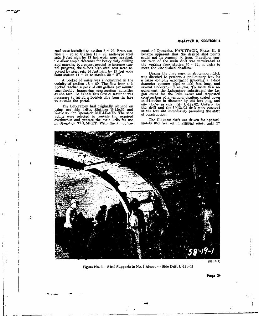
CHAPTER II. SECTION 4
roof were installed to station 8 + 95. From sta- ment of Operation HARDTACK, Phase II, ittion 8 + 95 to Station 11 + 98, arch-type steel became apparent that the desired shot pointssets, 9 feet high by 13 feet wide, were installed, could not be reached in time. Therefore, con-To allow ample clearance for heavy duty drilling struction of the main drift was terminated atand mucking equipment needed to increase tun- the working face, station 20 + 34, in order tonel progress, the 9-foot high steel sets were re- meet the ostoblished deadline.placed by steel sets 14 feet high by 13 feet wide Durig the first week in Septemb&, LRLfro m sta tio n 1 1 + 9 8 to sta tio n 2 0 + 2 7 .D ri g t e f st w k i n S p e b , L R
was directed to perform a preliminary test forA pocket of water was encountered in the a large complex experiment involving a 6-foot
vicinity of station 18 + 50. The flow from this diameter vacuum pipeline OO feet long, andpocket reached a peak of 560 gallons per minute several underground alcoves. To meet this re-coniiderably hampering construction activities quirement, the Laboratory substituted the Lo-at the face. To handle this flow of water it was gan event for the Pike event and requestednecessary to install a 14-inch pipe from the face construction of a vacuum pipeline scaled downto outside the portal. to 24-inches in diameter by 165 feet loug, and
one alcove in side drift U-12e.02. Criteria forThe Laboratory had originally planned on this drift and the U-12e.05 drift were received
using two side drifts, Stations U-12e.02 and at the test site immediately preceding the startU-12e.05, for Operation MILLRACE. The shot of construction.points were selected to provide the requiredoverburden and protect the main drift for use The U-12e.02 drift was driven for approxi.in Operation TRUMPET. With the announce- mately 650 feet with maximum effort until 27
-o
Figure No. 5. Steel Supports in No. 1 Alcove - Side Drift U-12b.03
Page 39

CHAPTER 11, SECTION 4
(58-27-12)
Figure No. 6. Steel Supports in Side Drift U-12e.05
September at which time the heading was stop- by LRL in July 1958. Each facility was to con-ped and GZ was established. An additional week sist of a short tunnel with a hook at the end, awa, allowed for construction of the blast door blast door, and a small alcove for one instrumentand completion of the coax cable installation, drill hole. These facilities were to be located offThe Users moved in their equipment on 4 Octo- the main access tunnel, Station U-12f. Theher and the Loga, event was detonated at the requirement for U-12f,05 side drift was deletedend of this drift on 15 October. in August and the length of the U-12f.04 side
The U-12e.05 drift for the Blanca event drift was increased to 155 feet.was driven to obtain the maximum overburden The final configuration of branch tunnelspossible and still protect +he main tunnel from off U-12f was as follows:collapse as a result of. stresses created by theLogan event. As additional protection, steel sets U-12f.01 155 feet, at station 3 + 707 feet wide by 9 '-,et high were installed on 4-footcenters for the first 500 feet. This drift was U-12f.02 155 feet, at station 4 + 30terminated ii a hooked-end configuration, atstation 10 -:- 10 and the casement for the blast U-12f.03 311 feet, at station 4 + 90door was poured prior to the Logan event in U-12f.04 155 feet, at station 5 + 30Station U-12e.02.
Considerable damage occurred to the main As a result of radioactive contamination intunnel as a result of the Logan event and a new the U-12f access tunnel, caused by the Mercury
tunnel was driven from station 17 -- 94 to the and Mars events, it was necessary to abandonportal of the U-12e.05 drift. Seven-foot wide the U-12f.03 and U-12f.04 side drifts and relo-steel sets were used through the twisted steel, cate the events scheduled for these locations totimber and rock debris. The U-12e.05 side drift, surface test facilities in Area 9.beyond that portion reinforced with steel sets In addition to the safety test installationshad collap,ed, and it was necessary to relocate in the U-12f tunnel complex, in September, sidp
GZ at station 5 + 97. drift Station U-12c.03 was excavated in the ex-Safety Tunnels isting Operation PLUMBBOB Tunnel U-12c.
This facility consisted of a 6-foot wide by 7-foot
The construc ion of five safety test facilities high by 165-foot long side drift off the main(Stations U-12f.01 through .05) was requested tunnel at station 1 + 00.
Page 40

fCHAPTER II. SECTION 4
Vertical Instrument Hales AREA 7
The Lump Sum Contractor moved on the On 12 September construction started ondrilling site 5 August, and Hole No. 5 was drill- the 100-foot tower, Station T-7c, for use in theed to a depth of 892 feet and cased with 4-inch Quay event, The station was erected from fourlighL weight well casing. 25-foot sections of a standard steel shot tower,
and 'as completed on 9 October.The first of the four remaining holes was
drilled to a depth of 101 feet when the Cnstruction for the balloon tests, Mora,Laboratm y stipulated relocation of the U-12e.05 1,ea, and Socorro, began 23 June with all faci-GZ and the four instrument holes. lities completed 11 September. Paving and re-
lated construction on the colemanile pad wasThe Contractor was then placed on standby completed in July.
for four days awaiting a firm location of the newGZ and the construction of an access road to the Seven light wood-frame structures (Stationsnew site. The drill rig was moved to the new 700.01 and .02, 701.01 and .02, 702.01 throughlocation and 169 feet of the first hole was drill- .03) were constructed for the balloon events.ed when the Users again relocated GZ. After Construction on these one and two-story struc-three days of standby time, it was decided to tures began 7 September and was completed 26move the cluster of four holes to a location above September. Following the first two events, theStation U-12b.04 GZ. The Contractor then mov- structures were rehabilitated, with repair ofed the equipment. to the third location and fractured transite sheets and broken wood tim-drilled and conditioned the four 8 -inch din- bers, as required.meter uncased holes as follows:
Hole No. 1 - 770 feet deep AREA 8Hole No. 2 - 471 feet deep During the last week of the Operation, Sta-Hole No. 3 - 763 feet deep tions 8a, 8b, and 8c were each constructed andHole No. 4 - 360 feet deep turned over to the Users in one day The stationswere identical 25-foot wood towers prefabricated
The instruments to be installed in the holes in the Area 12 sawmill for final erection at Areawere not at the site when drillingwas completed, 8 sites and foy use in the Oberon, Ceres and Ti-and during the interim period the holes became tania events. Station T-8a was started and com-plugged due to coagulation of the drilling mud pleted 20 October; T-8b, 24 October; T-Sc, 26and a sloughing action resulting from several October,test events in the area and nearby constructionblasting. As a result of this plugging, instru-ments could not be installed and it was necessary AREA 9to ream Hole No. i to 121/ irches in diameter, Construction for Area 9 events began 13and redrill and clean the other three holes just September and was completed 29 October.prior to the Users lowering and grouting theirinstrumenti. An existing concrete balloon GZ pad, Sta-
tion B-9a, required extensive rehabilitation foruse in the Rushmore event. This construction
OTHER AREAS was completed 22 September and included thepouring of a 4-foot thick reinforced pad over the
AREA 5 existing pad and a 14x3x6-foot high reinforced
Construction of Station T-F1, a 50 foot concrete wall across one end.wood tower for the Hamilton event, began on 15 Three heavy timber, 10 x 10 x 7-foot highSeptember. The tower and its three platforms "Gravel Gerties" with an entrance maze tunnelwere completed by the end of September, with 26x4x7 feet high were constructed for the Vesta,final completion of all related facilities on 13 Juno and Ganymede events. Construction acti-October. vity on these zero stations was started and com-
On 20 October construction began on Sta- pleted as follows: S-9e, 5 October-18 October;tion T-Fb, a 50-foot aluminum tower originally S-9, 5 October-17 October; S-9g, 20 October-schedulEd for the Humboldt event. However, 23 October.after the tower was erected and about 75% A 50-foot steel tower erected on four 9x9x3-complete, plans were changed. The Humboldt foot concrete footings was started on 30 Septem.event was rescheduled for Station T-3v, and the ber for use in the Mazama event. The tower andtower was dismantled and returned to the ware- all related facilities, including the prefabricatedhouse. shot cab, were completed 25 October.
Page 41
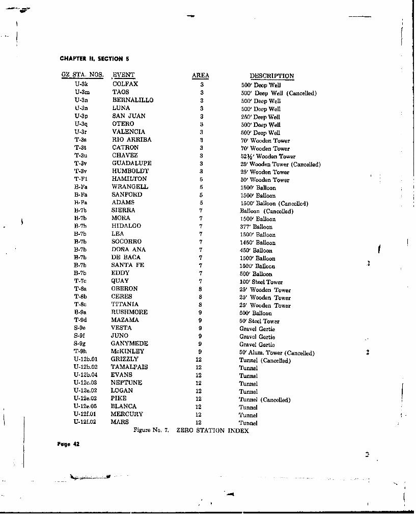
CHAPTER II, SECTION 5
GZ STA. NOS, EVENT AREA DESCRIPTIONU-k COLFAX 3 500' Deep WellU-3m TAOS 3 500' Deep Well (Cancelled)U-3n BERNALILLO 3 500' Deep WellLI-3n LUNA 3 500' Deep WellU-3p SAN JUAN 3 250' Deep WellU-3q OTERO 3 500' Deep WellU-3r VALENCIA a 500' Deep WellT-3s RIO ARRIBA 3 70' Wooden TowerT-3t CATRON 3 70' Wooden TowerT-3u CHAVEZ 3 52 %' Wooden TowerT-3v GUADALUPE 3 25' Wooden Tower (Cancelled)T-3v HUMBOLDT 3 25' Wooden TowerT-F1 HAMILTON 5 50' Wooden TowerB-Fa WRANGELL 5 1500' BalloonB-Fa SANFORD 5 1500Y Balloon13-Fa ADAMS 5 1500' Balloon (Cancelled)B-7b SIERRA 7 Balloon (Cancelled)B-Tb MORA 7 1500' BalloonB-7b HIDALGO 7 377' BalloonB-7b LEA 7 1500' BalloonB-7b SOCORRO 7 1450' BalloonB-7b DOrA ANA 7 450 BalloonB-Tb DE BACA 7 1500 BalloonB-7b SANTA FE 7 1500' BalloonB-7b EDDY 7 500' BalloonT-7c QUAY 7 100' Steel TowerT-8a OBERON 8 25' Wooden TowerT.8b CERES 8 25' Wooden TowerT-8c TITANIA 8 25' Wooden TowerB-9a RUSHMORE 9 500' BalloonT-9d MAZAMA 9 50' Steel TowerS-9e VESTA 9 Gravel GertieS-9f JUNO 9 Gravel GertieS-9g GANYMEDE 9 Gravel GertieT-9h McKINLEY 9 50' Alum. Tower (Cancelled)U-12b.01 GRIZZLY 12 Tunnel (Cancelled)U-12b.02 TAMALPAIS 12 TunnelU-12b.04 EVANS 12 TunnelU-12c.03 NEPTUNE 12 TunnelU-12e.02 LOGAN 12 TunnelU-12e.02 PIKE 12 Tunnel (Cancelled) IU-12e.05 BLANCA 12 TunnelU-12f.01 MERCURY 12 TunnelU-12f.02 MARS 12 Tunnel
Figure No. 7. ZERO STATION INDEX
Page 42

CHAPTER II, SECTION 5
SECTION 5TEST FACILITIES
STATION: Balloon Cab Shelters Plug No. 2 consistod of a 34-inch OD pipe,28 feet in length, filled with concrete to within
PURPOSE: Balloon Cab Shelter at 4 feet of the top and bottom. The bottom 4 feetZero Station contained a detector and instrument housing.
USER: LASL A 30-foot-square concrete slab at the sur-
PARTICIPATION: Mora, Eddy, Hidalgo, face supported a 20x20x60-foot high head towerWrangell, Lea, Rushmore, which was constructed from sections of a 300-Socorro, Dofta Ana, foot shot tower. The exterior of the tower wasSanford, De Baca, covered with plywood and painted with alumi-Santa Fe num paint. This tower was equipped with two
sets of double sheaves, mounted one above theEach cab shelter consistsd of a skid- other and a traveling 5-ton electric hoist for
mounted, plywood-covered, woOa.-Lrame struc- handling the upper plug.tore 161Ax16xl8 feet high. Access was pro-vided at one end by two sliding doors, each A User-furnished canister, which rested at8 x18 feet high. The skids were 6xl0-inch the bottom of the hole, and Plug No. 1 weretimbers. Each structure was equiped with elec- raised and lowered by means of two 8-tontrical facilities and an air cooler. hoists located approximately 60 feet from the
tower, with the hoist cables run over theSTATION: U-3k, U-3m, U-3n, U-3p, sheaves in the head tower. Control of the hoists
U-3q, and U-3r was from the tower.PURPOSE: Zero Station The hole for Station U-3p was originally
drilled to a depth of 500 feet; however, duringUSER: LASL the installation of the 36-inch casing, the
casing became wedged at the 192-foot level andPARTICIPATION: Colfax, Luna, Bernslllo, could not be pulled. Thirty-four-inch casing was
San Juan, Otero, Valencia then installed inside of the 36-inch casing to
CONSTRUCTION: U-3k, 5/28/58 - 8/29/58 the 810-foot depth, where it collapsed due toU-3m, 5/28/58 - 9/10/58 the removal of the hydrostatic head. This holeU-3q, 5/26/58 - 9/4/58 waa then bailed and filled with concrete to theU-3n, 5/26/58 - 9/10/58 250-foot levelU-3r, 9/9/58 - 9/22/58 STATION: T-3s, T-3t, and T-3u
, U-3p, 9/3/58- 10/8/58U-p, 9//5 -108/8 PURPOSE: Zero StationWith the exception of Station U-3p, which
was a 32-inch, 250-foot deep cased hole, each USER: LASLstation consisted of a 500-foot deep hole, cased PARTICIPATION: Rio Arriba, Catron,with 36-inch ID well casing having 7/16-inch PAvr twalls. The wells were capped with a 1inch thick Chavezsteel cover plate. CONSTRUCTION: T-3s, 10/14/58 - 10/17/58
The casing contained two plugs. Plug No. I T-3t, 10/20/58 - 10/22/58was located at the 250-foot level and consisted T-3u, 10/22/58 - 10/27/58of a concrete-filled steel cylinder, 34 inches OD With the exception of T-3u these towerby 5 feet long. To accommodate coax and signal stations provided 12xl2-foot platorms, 70 feetcables through the concrete plug, four pieces above grade. The elevation of the tower plat-of 6-inch pipe were cut in half lengthwise and form on Station T-3u was 52% feet aboveplaced on the inside perimeter of the casing. A grade. Each tower was constructed of four poles,length of 8-inch pipe ran through the center 80 feet in length, and extending below gradeof the plug and offset from this were two 2-inch approximately 10 feet. The towers were braceddiameter pipes located in opposite quadrants. with 2x2-inch cross-members.
Pug. 43
:tl
!N

CHAPTER 11. SECTION 5
Figure No. 8. Station T-St -90% .,Inplete
* Pageo44

CHAPTER II, SECTION 5
The cabs were 12x12x8 feet hiqh, were en- This station was originally planned to beclosed with plywood and had one pair of double- a duplicate of Station T-FI. Before constructionswing doors, 2 Ax7 feet each. Access to the began, however, it was changed to a prefabri-tower cabs was by wood stairways encircling the cated, 50-foot high aluminum tower. Erection oftowers, with landing platforms at approximately the aluminum tower was approximately 75%every 8 feet of tower height. complete when plans were again changed and
The towers were guyed with a 4 -inch steel the tower was dismantled and stored.cable from each of the four corners at the plat-form level. Guy cables terminated in 4x4x3-foot STATION: B-Faconcrete anchor blocks, buried below grade. PURPOSE: Balloon ZeroSTATION: T-3v USER: LRLPURPOSE: Zero Station PARTICIPATION: Wrangell, Sanford
USER: LRL CONSTRUCTION: 10/10/58 - 10/22/58
PARTICIPATION: Hunibolt Built for use during Operation PLUMB-
CONSTRUCTION: 10/25/58 - 10/27/58 BOB, this facility was repaired and modifiedThis station consisted of a wooden tower, for use in Operation HARDTACK, Phase II.
10x10x25 feet high, with 4x6-inch wood comer Repairs were made to the concrete pits,posts braced with 2x12-inch cross-members located directly below the balloon, which housedspaced at 8-foot intervals. A cab, 10xl0x7 feet the transformer and.EG&G and Sandia ingtru-high, was constructed on top of the tower and ments. The area around GZ was cleared, newwas completely enclosed with plywood, except cable was installed or spliced as necessary tofor a door opening, raise the balloon to 1500 feet, and the three
An intermediate platform was built at the existing winches were rehabilitated. Subsequent8-foot level, and all four sides of the tower were to the Wrangell event, new clean earth wasenclosed with plywood from the 8-foot to the hauled in and compacted around GZ to de-16-foot elevation. Wooden stairs encircling the contaminate the area for the Sanford event.tower provided access to the platforms at the8-foot and 25-foot elevations. STATION: F-803
The tower had no concrete base nor wasit secured by guy wires. PURPOSE: To Transmit TV Signalfrom GZ to CP Station
STATION: T-FI USER: SCPURPOSE: Zero Station PARTICIPATION: Wrangell, Sanford
USER: LRL CONSTRUCTION: 7/23/58 - 10/18/58
PARTICIPATION: Hamilton This station consisted of a wooden struc-CONSTRUCTION: 9/15/58 - 10/13/58 ture, 10x9x8 feet high, set on a 4-inch thick con-
crete floor slab. Mounted on top of this structureA 50-foot high wooden tower with three plat- were two parabola antennas, one directed to-
forms was constructed by erecting four 60-foot ward GZ and the other toward the Control Point,wooden poles, approximately 18 inches in dia- Various instruments, electrical outlets, workmeter, and encasing them in concrete footings benches, and one air-conditioning unit were in-which were 10 feet deep by 3% feet square, stalled inside the structure.The four poles were vertically stabilized with/-inch steel guy lines. Each platform was11 x81/A feet, with 1-inch thick plywood floor- STATION: 501.01 through 501.13ing. The top platform was completely coveredwith weather-tight canvas, forming the device PURPOSE: Animal Pensroom. A wooden stairway encircling the tower USER: DODprovided access to each platform level. PARTICIPATION: Hamilton
STATION: T-Fb CONSTRUCT!ON: 9/15/58 - 9/23/58
PURPOSE: Zero Station Each of these stations consisted of four
USER: LRL steel posts driven into the ground to within 2V.feet above grade. Using standard wire fence, an
PARTICIPATION: Cancelled 18x24-inch rectangular enclosure was formed. A
Page 45

CHAPTER 11, SECTION 5
JI-
(58-481-6)
Figure No. 9. Station T-F1 -100% Complete
Page 46

CHAPTER II, SECTION 5
piece of fencing was wired over the top, totally STATION: 506.01 through 506.09enclosing each pen. PURPOSE: Thermal Detectors
STATION: 502.01 through 502.96 USER: DOD
PURPOSE: Radiological Data PARTICIPATION: HamiltonCollectors CONSTRUCTION: 9/29/58 - 9/29/58
USER: DOD A 6-inch diameter hole, 3 feet deep, wasPARTICIPATION: Hamilton drilled at each etation and a 6-inch diameter
pipe extending about 2 feet above grade wasCONSTRUCTION: 9/24/58 - 9/26/58 placed in the hole to support a User-furnished
At each station a %-inch diameter pipe, thermal detector,5 feet 9 inches long, was driven into the ground,leaving 2 feet 9 inches extending above grade,On top of this pipe was attached a User-furnished STATION: 508.01 through 508.26film badge. PURPOSE: Testing Biological Speci-
mens for Blast EffectsSTATION: 503.01 through 503.04 USER- DODPURPOSE: To Collect Radiological
Data PARTICIPATION: Hamilton
USER: DOD CONSTRUCTION: 9/29/58 - 9/30/58
PARTICIPATION: Hamilton These stations consisted of rectangular holes,2x6x4 feet deep, with a 6-inch high berm
CONSTRUCTION: 9/15/58 - 9/26/58 built up around the top. These holes were notA hole, 8 feet deep and 19 inches in dia- covered during the test.
meter, was drilled for each station. A 12-inchthick concrete ring with a 3-foot outside dia- STATION: 509.01 through 509.26meter and a 19-inch inside diameter was instal-led at the top of the hole with the top of the PURPOSE: Testing Biological Speci-ring flush with grade. Each ring was cast with mens for Blast Effectsfour 1 -inch studs for use in mounting User-furnished instruments. USER: DOD
PARTICIPATION: HamiltonSTATION: 504.01 through 504.30 CONSTRUCTION: 9/15/58 - 9/23/58PURPOSE: Neutron Detectors and
Soil Samplers Each of these stations consisted of a rec-tangular hole, 2x6x4 feet deep. Two-thirds
USER: DOD of each hole was covered with 6x6-inch timbers,6 feet long, and 12 inches of earth fill, leaving
PARTICIPATION: Hamilton a 2-foot-square opening.CONSTRUCTION: 9/15/58- 9/24/58
Each station consisted of one piece of %- STATION: 510.01 through 510.12inch diameter wire rope, anchored at GZ andthen stretched for a distance of 3000 feet. User- PURPOSE: Testing Biological Spei-
* furnished neutron detectors and soil samplers mens for Blast Effectswere attached to this rope at varying distances USER: DODfrom GZ.
PARTICIPATION: HamiltonSTATION: 505.01 through 505.100 CONSTRUCTION: 9/15/58 - 9/23/58PURPOSE: Alpha Collectors A rectangular hole, 2%5x7 feet deep, with aUSER: DOD 2-foot-square step, 4 feet from grade, was ex-PARTICIPATION: Hamilton cavated for each of these stations. At the bot-
tom of the hole, 900 to the wall, a 24-inch dia-CONSTRUCTION: 9/15/58 - 9/30/58 meter, 4%-foot long corrugated metal pipe was
placed, with a holding ring attached at one end.Each station consisted of a concrete slab andbags were placed on top of this pipe to
10xl0x2 inches thick. These slabs were placed prevent its being filled with loose dirt. Roughly,on top of the giound at varying points from GZ. hfof the top of the excavated hole was covered
Page 47

CHAPTER II, SECTION 5
with 6x6-inch timbers and back-filled with 12 STATION: 522.01 through 522.10inches of earth, leaving an opening of approxi-mately 2 feet square. PURPOSE: Shadow Shield Detection
USER: LRLSTATION: 517.01 through 517.08 PARTICIPATION: HamiltonPURPOSE: Pressure Recording CONSTRUCTION: 9/24/58 - 9/26/58
USER: DOD These stations consisted of 10 telephone
PARTICIPATION: Hamilton poles extending 50 feet above grade and arrangedin two parallel rows of five poles, each poleCONSTRUCTION: 9/26/58 - 9/30/58 being opposite a pole in the other row. User-
A hole, 15 inches in diameter and 3 feet furnished detectors were attached to rope anddeep, was drilled for each station. A 15-inch chain catenaries suspended between each pairdiameter pipe was inserted into the hole and of opposite poles. Swivel blocks were used withextended about 2 feet above grade. A User- the rope to raise and lower the detectors. Atfurnished gauge was attached at the top of each six locations, facing in various directions frompipe. GZ a 6-inch pipe, 3 feet long, was placed in
a V-shaped hole and held in positiGn with sand-STATION: 518.01 through 518.27 bags.PURPOSE: Pressure-Time Recording
USER: DOD STATION: 523.01 through 523.03
PARTICIPATION: Hamilton PURPOSE: Testing Valves for Closure
CONSTRUCTION: 9/26/58 - 9/30/58 USER: OCDM
A 12-inch diameter hole, 18 inches deep, PARTICIPATION: Hamiltonwas drilled into the ground and 12-inch dia- CONSTRUCTION: 9/23/58- 10/7/58meter pipe was inserted in each hole, extendingabout 2 feet above grade. A PT gauge, furnished During Operation PLUMBBOB, three testby the User, was attached at the top of each cells were built of 7-foot, 7-inch diameter bypipe. 8-foot long concrete pipes, with 20-inch Lon-
(REECO 48-4)Figure No, 10 Generr View of Station T-Fl and Stations 522.01 through 522.,10
Page 48
-ij)
W

CHAPTER II. SECTION 5
~A
4t4
68 -3- )
Figure No. 11. Stations 523.01, .02 and ,03 - 100% Complete
crete covers. Thpse test cells were relocated on form of plywood decking was built at the 88-foota new concrete base, 30 feet, 9 inches long by 10 1-iiich level.feet, 2 inches wide, by 1 foot, 6 inches thick. A pipe of varying diameters, as listed below,One 12-inch, one 16-inch, and one 24-inch User- extended from the concrete plug in Stationfurnished valves were bolted in place on top of 7-313 to the cab floor.the cells. These valvus were electrically wiredand instruments were mounted inside to measure Elevation Diametervalve closure during the Hamilton event. bttm of Concrete
Plug to 24 feet aboveSTATION: T-7c grt~de 6-inch ODPURPOSE: Zero Station 24 feet to 53 feet,
6 inches above grade 20-inch ODUSER: LASL 53 feet. 6 inches ta
PARTICIPATION: Quay cab floor 34-inch ODCONSTRUCTION: 9/1.2/58 - 10/9/58 Each corner of the tower was guyed at the
This station was irccted from four 25.foot 1O-foot level with 1-inch cables connected tosections of a standard steol shot towe-r. A existing concrete anchor blocks.20x20x8-foot high wooden cab was built on topof the tower, the cab floor being 103 feet, 2 STATION: 7-313inches above grade. The cab floor was of Ih-inchplywood decking and supported a paraffin shield, PURPOSE: Tower Base Structure2 feet thick and 10 feet in diameter. Access to USER: LASLthe cab was by elevator.
A platform at the 49 -foot level was built PARTICIPATION: Quayof 1-inch thick steel grating, and another plat- CONSTRUCTION: 0/22/58- 10/7/58
Page 49
'-~-~--

CHAPTER 11, SECTION 5
:. ,, ....4.
r ,
F i u e N , 1 . T oet t o c n a e S r c ur•t t o - 1 ( 5 8 .1 -4 )
Page SO
INN
:_. ..., .:. -. - ... .. .. ... , ... ....- . ...
vNN
I "LI~v
Figue N , 1 . T werStaton -7c an Bae Stuctre taton -31

CHAPTER II, SECTION 5
Modifications to this existing structure in- STATION: 700.01 through 700.02volved adding a steel door at the entrance-tunnel opening and removing a boiler from the PURPOSE: Radiation Dosimetry forbase-house structure. Human Exposure
The steel door was mounted on angle-iron USER: CETOtracks and so constructed that it could be open- PARTICIPATION: Mora, Lea, Socorroed from a remote location by pulling on an CONSTRUCTION; 9/7/58- 9/26/58attached steel cable.
These one-story structures were consLruct-When the boiler, which included a previous ed of timber frame and specially fabricated twans-
Lower footing, was removed from the ha5e-house, ito panel. They were 28 feet, 4 inches long,the resultant void was filled with a concrete 22 feet, 4 inches wide and the caves were 8 fot,plug, A 6-inch pipe ran through the center of 8 inches above grade. TIhe plywood floor was nail-tho plug, terminating at a 3-inch steel plate ed to floor joists which were mounted on fourmourted flush with the ceiling. Also, the exist- 12x12-inch skids. The roof slope was 5 to 12.ing tower footings were modified to accommo- Door and window openings were framed into thedate a 103.foot steel shot tower. outside walls; however, doors and windows were
not installed, Interior partitions were erected toA concr 'Je wall was constructed across the simulate a standard room arrangement. Thew
top of the tunnel structure near the entrance two Type "A" structures were re-oriented orto retain new fill over this station. relocated at 3000 feet from GZ prior to eachof three cvents.
In conjunction with sample recovery, asled was constructed of steel members with re- STATION: 701.01 through.02movable plywood sides. A steel tow cable wasattached to the sled and ran to the exterior of PURPOSE: Radiation Dosimetry forthe station. Iluman Exposure
. (5.23.9) ,
Figure No. 13. Stations 701.01 (Ilight) and 702.02 (Left)
PuNge S1
N,

CHAPTER ii. SECTION 5
W--
(REECO 480.6)
Figure No. 14. Stations 700, 701 and 702 - Area 7
USER: CETO eaves 8 feet, 8 inches above grade. The roof slopewas 5! to 12. The floor was plywood nailed toPARTICIPATION: Mora, Lea, Socorro floor joists which were mounted on three 12x12-
CONSTRUCTION: 9/11/58- 9/26/58 inch skids. Door and window openings wereframed into the outside walls, but doors and
These two-story structures were of wood windows were not installed. Interior partitionsframe and specially fabricated transite panel were erected to simulate a standard room ar-construction. They were 37 feet, 6 inches long, rangement. The Type "C" structures were used22 feet wide, and the eaves were 22 feet, 2 inches in three separate events by locating them afterabove grade. The roof slope was 6V to 12. Both each test.floors were plywood; the first floor rested on five12x12-inch skids. Door and window opening3were framed into the outside walls; however, STATION: T-8a, T-8b, T-8cdoors and windows were not installed. Interiorpartitions were erected to simulate a standard PURPOSE: Zero Towerroom arrangement, Bofh structures were used intwo events, and one structure was used in a USER: LRLthird event. These stations were located 3000 PARTICIPATION: Oberon, Ceres, Titaniafet from GZ during the three events. CONSTRUCTION: T-8a 10/22/58- 10/23/58
T'8b 10/24/58 - 10/24/58STATION: 792.01 through 702.03 T-Sc 10/26/58 - 10/26/58
PURPOSE: Radiation Dosimetry for Each station consisted of a 25-foot towerHuman Exposure with a 10xl0x7-foot cab erected at the top.
USER: CETO The towers were constructed of 4x6-inch postsand 2x6-inch cross-bracing. Three sides and the
PARTICIPATION: Mora, Lea, Socorro roof of the cabs were sheathed with plywoodCONSTRUCTION: 9/7/58- 9/26/58 and one side was covered with paraffin. The cab
floor was built of 2-inch plank on 2x8-inch joist.These one-story structures were con- Access to the cab was through a 5-foot-square
strueted of timber frame and specially fabricated hatch and through a door opening at the headtransite panel and were 26 feet square with of a stairway.
Page 52
4!,
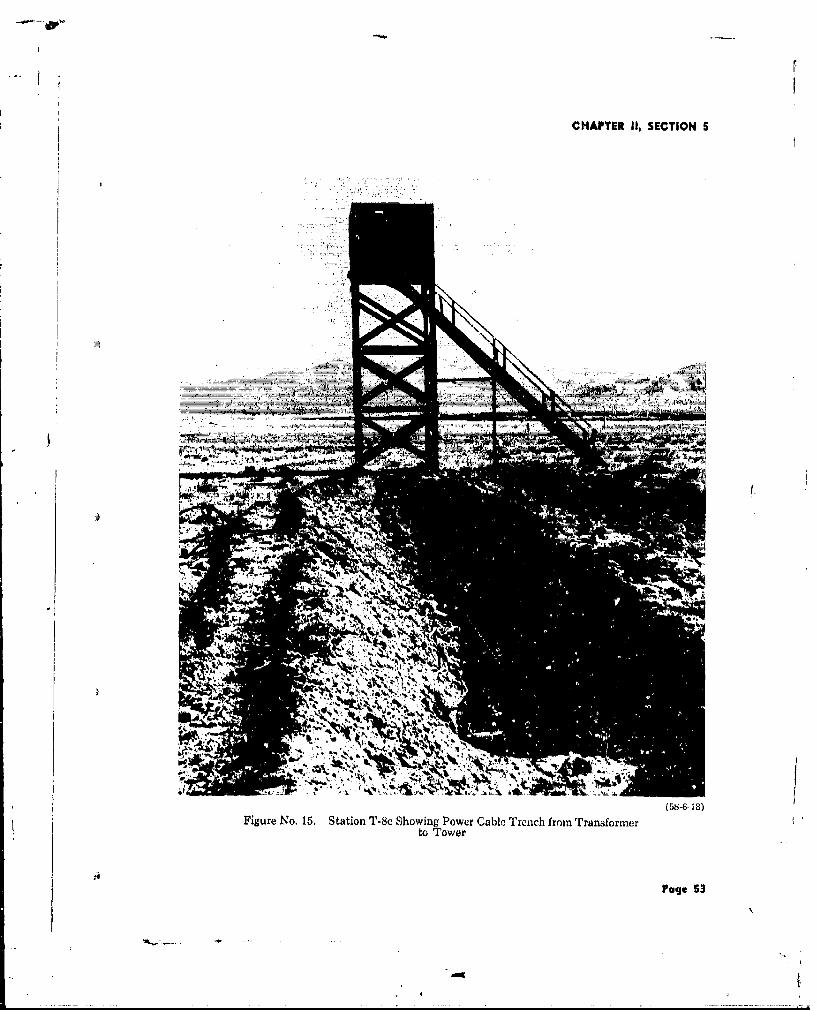
CHAPTER II, SECTION 5
- i :., " - 7i•
F _z
Figure No. 15. Station T-bc Showing Power Cable Trec ch fr e Transformerto Tower
Page 53

CHAPTER II, SECTION 5
STATION: B-9a feet, 10 inches wide by 5 feet long, 18 inchesdeep, and tapered concrete walls on two sides,PURPOSE: Balloon Zero Station 8 inches wide at the top and 20 inches wide at
USER: LRL the bottom, leaving a 2/2x5-foot long space atthe top. The open ends were enclosed with ply-PARTICIPATION: Rushmore wood.
CONSTRUCTION: 9/13/58 - 9/22/58 On top of these walls a 6x6-inch angle-ironThis structure, an existing concrete GZ box section, 5 feet long, was filled with grout
pad used for previous balloon launchings, had and supported the phonex block. Two fee. ofbeen damaged from past events and required ex- earth fill covered the phonex block and its sup-tensive rehabilitation and construction. This was port.accomplished by pouring a 4-foot thick rein.forced concrete pad over the existing pad and STATION: 904.01 through 904.03adding a 14x3x6-foot high reinforced concrete PURPOSE: Personnel Safety Shelterswall acroas one end. The wall contained twoTV alcioves, one transformer alcove, and one USER: OCDMterminal alcove. Steel doors were provided forall alcoves. PARTICIPATION: Rushmore
CONSTRUCTION: 9/17/58 - 10/1/58STATION: 902.01 These stations were underground rein-
forced concrete shelters, 12x9 6x7 feet high,PURPOSE: Camera Support covered with 21/4 fee.' of earth fill.USER: LRL To provide a passageway into the mainPARTICIPATION: Rusbmore room, a concrete partition, 8 inches thick, ex-
tended from one end wall of the structure toCONSTRUCTION: 10/13/58 - 10/17/58 within 2 feet of the other end wall.This stition was a phonex-camera-block- Access to the shelter was by a 2x3-foot
support consisting of a concrete foundation, 5 hatch which entered into the passageway
t. - " . ...; .. . ..
" , -. - " ' - ! ? -
~~7.7
Figure No. 16. Station B-9a Showing New Concrete Pad and Wall
Pago B4

Wr
CHAPTER II, SECTION S
Figure No, 17. Station 904 Prior to BacktUl,
through the top of the main strucure. The gravel. Timber wing walls %tended 24h feethatch was covered with a %-inch thick steel out from the tunn en+rance at approximatelyplate. Vent pipet, were provided for tho circL- 450 angles.-ation of fresh a;.r. A 200-foot Rad-Chem line connected eachstructure to a pumtp that was protected by a
STATION: S-9e, S-9f. and S-9g concrete wall and saz:d bags.
PURPOSE: Zero Station STATION: T-9dUSER: LRL PURPOSE: Zero TowerPARTICIPATION: Vesta, Juno, Ganymede USER: LRLCONSTRUCTION: S-Se, 10, 5/58 - 10/i/58 PARTICIPATION: Mazama
S-gf, 10/ 5/58 .10/1.7/58S-r, 10/20/58 - 10/23/58 CONSTRUCTION: 9/30/58 - 10/25/58
This structure consisted of 50-foot steelThese station? were hea,,y-timber structures, tower erected on Icur 9x9x3-foot concrete foot-each comprising a room 10xI0x7 fekt high withan entrance-maze tunnel zGx4x7 feet high. The frgs.structures were built on 18-inch thick cowcrete The tower wa6 topped with a 20x20x10-fcundations, and were covered with 20 feet of foot high timber cab covered with plywood. The
Page z5
* AM

CHAPTER II, SECTION 5
-11c
Figure No. 18. Station S-9f 100% Complete
cab was provided with one 3x7-foot door, two USER: LRL21/x0-foot, 10-inch doors, and a 5x5-foot access PATCAIO:Rs oehatch in the roof. A steel stairway encircling the PATC AIO:Rsmrtower provided access to the cab. CONSTRUCTION; 10/13/58 - 10/17/58
Equipti-ent was delivered to the cab by a This was an existing reinforced concrete1-ton electric hoist traveling (in a trolley beam structure. Due to the proximity of the Rushmorecantilevered out 9 ieet from the towor. event, it was necessary to install 6x6-inch crib-
bing on the inside for the full depth of the struc-STATION: T-9h ture. To provide a protective roof ever the pit,
PURPOE: Zro Sttioneight 12x12x-inch wide-11auge beamns coveredPURPSE: ZeroStaionwith plywood were installed, over which was
USER: LRL placed a 6-foot fill covered with sandbags.
PARTICIPATION: Cancellcd STATION: 9-308A tower 4 feet, 23/ inches by 1i feet, 9 5/s PURPOSE: Coax Connector Pit
inches by 50 feet high, consisting of aiuminumscaffolding, was erected on a concrete foundu- USER. LRLtion. With the exception of the cab, this structurewas completed; however a program revisioni do- PARTICIPATION: Vistaleted the requirement for this station azid it was CONSTRUC'I ION: 10/14/58 - 10/16/58Jismantled an~d placed in storage at Mercury. Two walls ot this existing structure wereSTATION: 9,303 cracked vertically, necessitating added reinforce-
ment prior to a test event occurring in the im-PURPOSE: Coax Connector Pit mediate vipirity. The reinforcing included the
Page 54
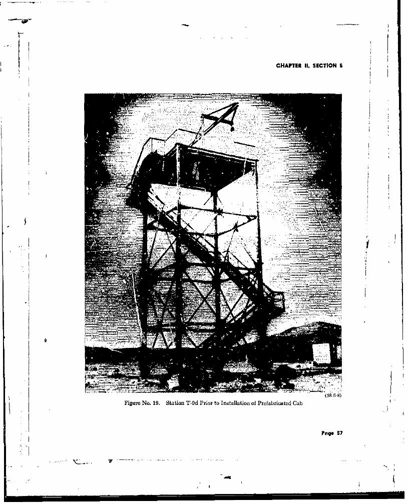
CHAPTER 11, SECTION 5
Figure No. 19. Station T-9d Prio~r to Installation of Prefabricated Cub
Pa~ge 57

CHAPTERt 11, SECTION 5
installation of 6x6-inch timber cribbing inside USER: LRLfor the full depth of the station 6x6-;nch tim-bers across, the top, sheathing the top timbers PARTICIPATION- Tamalpais, Evanswith plywood, and covering the structure with CONSTRUCTION: U.12b,0l - 297-foot brancha 2-foot earth fill overlaid with sandbags. tunnel off U-12b tunnel at
station 4 + 84, 6/10/58STATION: 9-310 to 11/17/58
PURPOSE: Com; Copnoetor Pit U.12b.02 - 394-foot branchtunnel off U-12b tunnel at
USER: LRL station 6 + 67, 5-19-58PARTICIPATION: Ganyinede to 10/8/58
CONSTRUCTION: 10/29/58 - 10/'29/58 U-12b.03 - 655-foot branchtunnel off U-12b tunnel at
This structure was reinforced and protect- station 9 + 66, 6/4/58ed in the same manner as Station 9-308. to 11/17/5S
STATON: -12b01,.02,.03,.04U-12b.04 - 829-foot branchSTATON:U-1b,0, .2, 03,.04tunnel off U-12b tsunncl at
PURPOSE: Side Drifts into GZ station 14 d1- 00, 3/20/58Chambers to 10/28/568
7iur No00 unlU1b hwn oeSgal n ox al
Intalaio
Pagimi9
.13

CHAPTER II. SECTION 5
~V4A
* Figure No. 21. Transition from Wire Mesh to Steel Supports in Side Drift U-12b.04
Page 59

CHAPTER II, SECTION 5
Figure No. 22. Wire Mesh Used to Support Roof in Side Drift U-12b.04
The main drift of Tunnel U-12b was in ex- drift lining, equipment, and trackage were theistence prior to the octivity described below, same as described for drift U-12b,01. DriftThis tunnel was 1940 feet long with a 6x7-foot U-12b.02 was used for the Tamalpais event,high cross-section.
Drift U-12b.01 was excavated to include a Drift U-12b.03 was constructed to in-GZ chamber and an alcove (Alcove No. 1) con- elude a GZ chamber and two large alcoves (Al-taining two large rooms and two small alcoves coves No. 1 and No, 2), The GZ chamber wasfor drilling purposes. A 19xl5x13-foot high GZ about 19x19x14 feet high, and was lined withchamber was lined with steel beams, timber steel beams, timber posts, and timber lagging. Al-posts, and -timber lagging. For re-entry purposes, cove No. 1, rectangular in plan, was supported byAlcove No, 1 was completely lined with lagging steel arches with 7-foot horizontal beams, al-over steel arches. The entire drift was lined with lowing a clear height of 9% feet and a width ofsteel arches, allowing a 6 -foot width and 20 feet. Alcove No. 2 was completely lined with8 /-foot clear height, A single track railroad lagging over steel arches, An accidental explo-was used in the tunneling operations. The drift sion in drift U-12b.02 damaged drift U-12b.03was provided with compressed air, power, light, to the extent that it could not be used for a testventilation, and vater. U-12b01 was not used event during this Operation.in this Operation due to a rescheduling of events. Drift U-12b,04 was excavated to include
Drift U-12b.02 was excavated to include an irregular-shaped GZ room, three large alcovesa GZ chamber and an alcove (Alcove No. 1) (Alcoves No. 1, No. 2, and No. 3), and severalcontaining two large rooms, a camera and rack small drilling alcoves. The GZ room was linedroom, and two small drilling alcoves. The GZ with steel beams, timber posts, and timber lag-chamber was 19x19x12 feet high, and was lined ging. Alcoves No. 1 and No. 2, rectangular inwith steel beams, timber posts, and timber lag- plan, were supported by steel arches as describ-ging. The interior of the GZ chamber was lined ed in Alcove No. 1, drift U-12b.03. Alcove No,with salt blocks which were held iv place with 3, irregular in plan, was lined with steel beamsplywood. Alcove No. 1 was lined with timber and columns. Utilities and trackage similar toand steel arches. The camera and rack room those in drift U-12b.01, were installed. Thiswas framed with steel beams and columns. The drift was used for the Evans event.
Page 60
_= .-.-..I

CHAPTER 13, SECTION 5
*1 1
V~
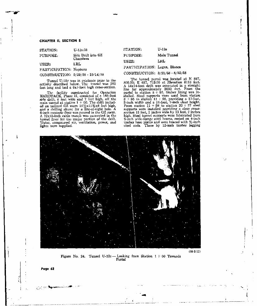
CHAPTFR II, SECTION S
STATION: U-12e.03 STATION: U-12e
PURPOSE: Side Drift into GZ PURPOSE: Main TunnelChambers
USER: LRLUSER: LRL
PARTICIPATION: Neptune PARTICIPATION: Logan, Blanca
CONSTRUCTION: 9/29/58 - 10/14/58 CONSTRUCTION: 3/21/68 - 8/30/58
Tunnel U-12c was in. existence prior to the The tunnel portal was located at N 887,
activity described below. Thi: tiinel wa 200 809.00; E 637, 719.00 at Elevation 6115 feet.
feet long and had a 6xT-foot high cross-section, A 14x14-foot drift was excavated in a straightline for approximately 2030 feet. From the
The facility constructed for Operation portal to station 8 + 95, timber lining was in-HARDTACK, Phase 11, consisted of a 165-foot stalled. Steel supports were used from stationside drift, 6 feet wide and 7 feet high, off the 8 + 95 to station 11 - 98, providing a 13-foot,main tunnel at station 1 + 00. The drift includ- 2-inch width and a 11-foot, 7-inch clear height.(d an unlined GZ room 15%xl1 2/jx8 feet high, From station 11 d- 98 to station 20 -I- 27 steeland a drilling alcove for a line-of-sight hole. A supports were installed providing a clear cross-6-inch concrete floor was poured in the GZ room. section 13 feet, 2 inches wide by 13 feet, 2 inchesA 12x18-inch cable trench was excavated in the high. Steel tunnel supports were fabricated fromtunnel floor for the major portion of the drift. 6-inch wide-flange steel beams, rested on 4-inchWater, compressed air, ventilation, power, and timber base plates and were braced with -inchlights were supplied. iteel rods. Three by 12-inch timber lagging
(58-2-12)
Figure No. 24. Tunnel U-12c - Looking from Station 1 + 00 TowardsPortal
Page 62
. .. ...... ... .. . . .. . . . . .

CHAPTER II. SECTION 5
Figure No. 25. Transition from Timber Sets to Steel Sets at Station 8 + 95Tunnel U-12e
was placed between the steel supports. Ventila- a clear width of 7 feet. These were usedtion was provided through two 20-inch round from stations 0 + 25 to 0 ± 43 and f r ) mducts suspended from supports at the center 4 + 27 to 4 + 83. Between stations 0 + 96 andline, Power and signal cables were carried in five 1 - 14, 6x8-inch timber sets were used. The13-inch suspended cope trays. Other utilities in- drift was widened by approximately 1 toot fromcluded a 4-inch water line and a 6-inch corn- station 4 + 34 to the end of the drift. The GZpressed air line. A double track railway extended chamber was located at the end of the driR andfor the full length of the tunnel, was of the same dimensions as the drift.
STATION: U-12e.02 and .05 U-12e.05
PURPOSE: Side Drifts into GZ This side drift was constructed off TunnelChambers U-12e at station 19 - 61. It extended 1010 feet
USER: LRL and included a GZ room lined with 8x8-inchtimbers to a height of 14 feet. A large loop re-
PARTICIPATION: Logan, Blanca versed the direction of the drift to form an earthplug at shot time. Steel lining sets, having aCONSTRUCTION: U-12e.02 - 8/29/58 to 34-foot radius and a 5%-foot column section,10/15/58 provided a clear width of 7 feet.
U-12e.05 - 8/29/58 to The Logan event in U-12e.02 damaged a,10/30/58 considerable portion of the U-12e.05 drift, neces-
sitating relocation of the GZ room to stationU-12e.02 5 + 97. The new GZ room was 7 feet, 7 inches.
From the main drift of Tunnel U-12e, wide and was supported by 6x8-inch timberstation 20 + 31, a 665-foot side drift was exca-vated with one small diagnostic alcove and a Both drifts were equipped with a singleGZ chamber. Steel lining sets, having a 3%2-foot track railroad, water, compressed air, ventila-radius and a 5%-foot column section, provided tion, power, and lights.
Page 63
i~N.

CHAPTERl 11, SECTION 5
-T,
Figure No. 26. Steel Sets at Statio~n 12 +I 17- Tunnel U-12c
Page 64

CHAPrIR 11. SECTION 5
STATION: U-121 centers, These supports also carried a 20-inchround ventilation duct, a 2-inch water line andPURPOSE: Main Tunnel a 4-inch comnpressed air line, The power cable
USER: LRL was supported on the tunnel wall by rock boltsspaced on 5-inch centers. A single track railway
PARTICIPATION: Mercury, Mars serviced this tunnel.
CONSTRUCTION: 8/1/58 - 9/13/58This was a 550-foot long tunnel with a cr'oss. SAIN -2.1 0,.3 0
section of 6,0 feet, located at N 887, 666.50; PURPOSE: Side Lirifts into GZE 636, 115.00 at Elevation 6712 feet, Th tun- Chambersnel terminated in a room 14x15x10 feet highand was provided with a blast door and a diag- USER- LRLnostie alcove. Two steel supports were install- PARTICIPATION: Mercury, Marsed for personnel sahty at the junction of theU-12f.03 side drift. Signal cable was housed in CONSTRUCTION: TU-12f.01 - 155-foot bran~cha 6xl2-inch timber tray which was supported on tunnel off U.12f at station4x4-inch pusts and beams spaced on 8-foot 3 d- 70, 8/28/58 - 9/22/58
V

CHAPTER II. SECTION 5
U-12f,02 - 155-foot branch of 23 feet, 6 inches, and a width of 17 feet, 6tunnel off U-12f at station inches. One end of the building was open with4 + 30, 8/31/58 - 9/27/58 access limited by a chain link fence and gate.
U-12f.03 - 311-foot branch The opposite end was supported by two steelcolumns which framed into a horizontal beam.
tunnel off U-12f at station Two-by-twelve planking was secured Lo the out-4 + 90, 9/7/58 - 10/15/58 side flanges of the arches and 22-gauge corru-
U-12f.04 - 155-foot branch gated metal siding was nailed over this. Onetunnel off U-12f at station 10-kw and one 35-kw generator set were vented5 + 30, 9/10/58- 10/15/58 by stacks through the roof. Two 550-gallon fuel
oil tanks resting on concrete cradles were placedDrifts U-12f.01 and .02 were "onstructed on one side of the building to supply fuel for
with a %Z room, an adcove for a line-of-sight the generators.hole, and a small alcove for a transformer andpanel. Each GZ room was 15x14x8 feet high,and had a 6-inch concrete slab floor. The roomswere unsupported. Drift U-12f.03 was excavated STATION: 12-300to station 2 + 61 and was then deleted fromthe program. The excavation of U-12f.04 was PURPOSE: Alpha Recording Stationconcluded, but further work to complete the USER: LRL.aicility was discontinued. PARTICIPATION: Tamalpais, Evans,
Typical drift construction included excava- Neptune, Mercury, Marstion 6 feet wide by 7 feet high which was un-supported except for a few steel arch sets. Timber CONSTRUCTION: 6/30/58 - 9/27/58sets were erected on 8-foot centers to support This existinig rigid-frame, aluminum-coveredan overhead cable trough. All drifts were sup- building was lengthened by 20 feet. Constructionplied with water, compressed air, ventilation, of the new additicn matched the existing struc-power, and lights, ture. Partitions were relocated to enlarge Rooms
Only drifts U-12f.01 and U-12f.02 were 104 and 105. The 500-gallon water tank wasused in this Operation. relocated to a corner of the new extension. A
4-inch concrete slab, 10 x7l/3 feet, was addedat the west side of the building for two dehumid-
STATION: 12-1 ifiers. A removable roof was erected over the
PURPOSE: Forward Observation and front entrance, and the air conditioning ductsControl Point were extended into the new section.
USER: LRL
PARTICIPATION: Evans, Blanca STATION: 12-301
CONSTRUCTION: 10/23/58- 10/27/58 PURPOSE: Alpha Recording Station
This station included a trailer, various USER: LRLequipmeni., and parking areas. One parking PARTICIPATION: Logan, Blancaarea, 300x30 feet, was located on the south sideof the Area 12 access road. The trailer, en- CONSTRUCTION: 8/,4/58 - 10/15/58closed by a 40-foot-square, two-strand barbed This station was built on a 6-inch con-wire fence, was located at the west end of thecparking area. The trailer was equipped with a crete slab and consisted o. a standard corru-receiving antenna and TV moenitor, and a hot gated metal arch building, 80x26x15 feetline, with two telephones, to the Control Point. high. The multinlate arches had a radius of 12Another parking area identical in size, was feet, 8 inches and were supported by 6-inch re-loate arkg teroade a inforced concrete side walls which were 2 feethigh above the finish floor. The outer surface
of the multiplate arch was covered with 3STATION: 12-63 inches of insulation. A concrete vault, 21 x
131%x8 feet lU1gh, was constructed adjacent toPURPOSE: Generator Shelter the north side of !he building. The east end wallUSER: LRL of the building was constructed of 10-inch re-
inforced concrete and contained the main en-PARTICIPATION: Logan, Blanca trance doors. The west end wall was constructed
of 12-inch reinforced concrete with an open slot9/2/58 - 10/24/58 through which conduit was run into the portal
The bulding was constructed of steel arches of Tunnel U-12e. After the conduit was in place,with a clear height of 13 feet, 2 inches, a length the slot was filled with grout.
Page 66

CHAPTER II. SECTIONS5
Figure No. 28. Interior of Station 12-001 Showing Ductwork ardElectrical Supports
Figure No. 29. Staaion 12-301 Prior to Backfill (82-0
Page 67

--- 4--
CHAPTER II, SECTION 6
The inside of the structure was partitioned wall was built to the embankment with ainto five rooms, as follows: right angle wing; it extended to the wood re-
taining wall on the opposite side, and the heightnstrum nt Room, 25'-4"x42'-2" was designed to contain the fill along it con-Work Room, 27'x14'-6' tour.Physics Diagnostics Space, 22'x10'Dark Room, 8'x9'-2"1Mechanical Equipment Room, 10'x14'-2" STATION: 12-302Air conditioning was supplied to all rooms PURPOSE: Warehouse
through metal ducts located at the ceiling line.Power for utilities was supplied from the main USER: LRLtransmission line through transformers housed PARTICIPATION: Not Applicablein the concrete vault. Scientific power was sup-plied from two generators located in Building CONSTRUCTION: 7/17/5S . 9/25/5812-63. This building was a standard steel, rigid-
The south side of this structure abutted frame structure, 49 feet, 101 inches long, 40a vertical embankment. Earth fill covered the feet, 21 inches wide arid 14 feet, 21 inchesbuilding with a minimum depth of 4 feet at the to the eaves, constructed on a 4-ilch concretecenterline, sloping off to the embankment on slab. The exterior was ceve'.d with aluminumthe south side and to a 4-foot high wood retain- panels. The front and rear of the building hading wall erected 15 feet from the north side of double sliding doors and two fixed windows,the building. The fill partially covered the con- Heat was supplied by two electric heaters, andcrete vault. The east end wall extended beyond for cooling an evaporative cooler was installedthe building to retain the fill at this end. This on a timber stand outside the building.
-'7 77-", 7 A
Figure No. 30. Station 12-302
Page 63
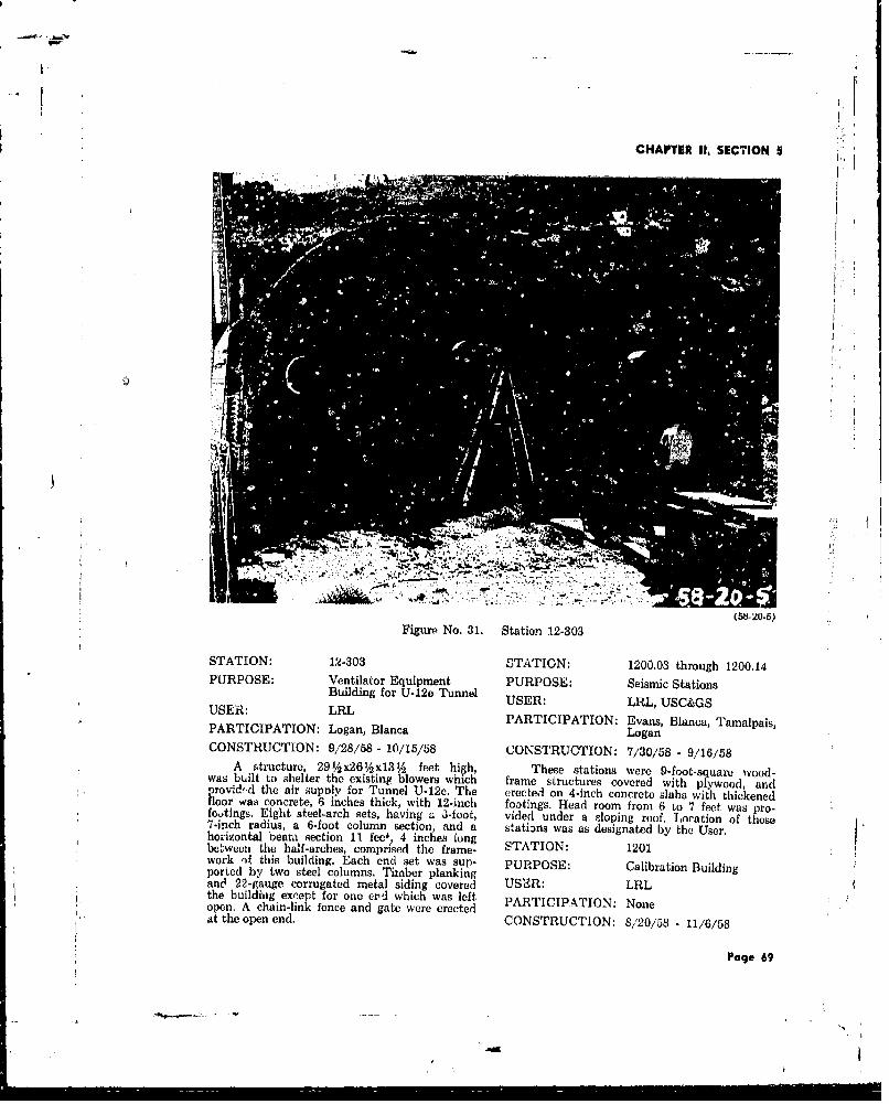
CHAPTER II, SECTION 5
(58.20-5)Figure No. 31. Station 12-303
STATION: 12-303 STATION: 1200.03 through 1200.14PURPOSE: Ventilator Equipment PURPOSE: Seismic Stations
Building for U-12e Tunnel USER: LRLUSC&GSUSER:. LRL PARTICIPATION: Evans, Blanca, Tamalpas,PARTICIPATION: Logan, Blanca LoganCONSTRUCTION: 9/28/58 - 10/15/58 CONSTRUCTION: 7/30/58 - 9/16/58
A structure, 29'Ax26x13A feet high, These stations were 9-foot-square wood-was built to shelter the existing blowers which frame structures covered with plywood, androvid.d the air supply for Tunnel U-12e. The erected on 4-inch concrete slabs with thickenedfloor wa8 concrete, 6 inches thick, with 12-inch footings. Head room from 6 to 7 feet was pro-foutings. Eight steel-arch sets, having a i-foot, vided under a sloping roof. Location of these7-inch radius, a 6-foot column section, and a stations was as designated by the User.ho-izontal beam qection 11 feel, 4 inches longbetween the half-arches, comprised the frame- STATION: 1201 I.work )f this building. Each end set was sup- PURPOSE: Calibration Buildingported by two steel columns. Timber plankingand 22-gauge corrugated metal siding covered US'0R: LRLthe building except for one ezd which was left PARTICIPATION: Noneopen. A chain-link fence and gate were erectedat the open end. CONSTRUCTION: 8/20/58 - 11/6/58
Page 69

CHAPTER II, SECTION 5
This station was a standard rigid-frame on 12-inch-cube concrete footings spaced 8 fetmetal building, Sx20x1O feet high to the caves, apart. Portable power was provided.constructed on a 0-inch thick concrete slab. In-terior wall and roof surfaces were insulated with Stations 1205.18 aad .19 were identical to1 v-inch material, A 315-gallon fresh-water stor- the above towers, except they were 6 feet inage tank, mounted on a platform outside the height.building, was connected to r. sink in the work-ing area. Electricity was provided by the maindistribution system. A 10-foot-square wood-frame building was added on the east side to STATION: 1206; 1207,01 throughhouse a 10.ton refrigerated air cooling unit. 1207.04Parking areas were provided. PURPOSE: Pro and Postshot
Radiation shielding was provided by a Measurements6-inch concrete wall, 8 fect high, which wasconstucted 12V2 feet from the south end of USER: LRL, SRI, SCthe building. This was a free-standing wall, PARTICIPATION: Evansending 3 feet, 8 inches from each side of thestructure. Two concrete baffle walls extended CONSTRUCTION: 8/5/58 - 10/23/58out 4 feet, 8 inches from each side wall on a All stations were vertical drift holes lo-line 3 feet north of the free-standing wall. This cated on the mesa above Station U-12b.04. Withwall arrangement provided adequate shielding the exception of Station 1206, all holec., con-for the calibration room as well as access to tained detection instruments lowered on cabler.the south end of the room. After instrumentation was completed, 120.0
A metal-covered cable trench in the floor through 1207,04 were filled with a special lightextended from the north end of the building weight grout. Station 1206 was filled withi waterto a point 18 inches south of the cross-wall. A and drilling mud and had no instrurientat0n.monorail, extending the entire length of the Following is a brief description of the stations:building at the roof ridge, supported a 2-ton Station 1206 892 feet deep, 8 /-inchelecrric hoist, diameter, with 4-inch
Access to the large open area was provided casingby 6:7-foot high double doors located in the Station 1207.01 770 feet deep, 121/4 -inchside wall, and by 8x8-foot double doors in the diameter, uncasedend wall. A single door, 3x7 feet, was locatedin the work area behind the concrete cross-wall. Station 1207.02 471 feet deep, 8%-lnch
diameter, unca-edSTATION: 1202 Station 1207.03 763 feet deep, 8 -i/ich
diameter, uncasedPURPOSE: Camera ShelterdimerunadUSER: EG&G Station 1207.04 360 feet deep, 84-inchdiameter, uncasedPARTICIPATION: Tamalpais, Evans,
Logan, Blanca
CONSTRUCTION: 9/26/58 - 10/17/58 STATION: 1208.01 and .02
A 12xl2x8-ioot high wood frame, plywood PURPOSE: Vacuum Linecovered shelter, supported on a 10-inch con- USER: LRLcrete slab, comprised this Area 12 station. Ac-cess into the structure was through two 6x7-foot PARTICIPATION: Mercury (1208.01) andhigh doors. Mars (1208.02)
CONSTRUCTION: 8/5/58 - 10/23/58STATION: 1205.01 through .19 These stations consisted of 6-inch diameterPURPOSE: Photo Tower Marker uncased holes vertically drilled from the ground
Lights surface into the GZ room of Stations U-12f.01and U-12f.02. Each hole was capped with a con-USER: EG&G crete slab 6 feet square and 6 inches thick.
PARTICIPATION: Evans A 1-inch, schedule 40 pipe extended fromCONSTRUCTION: 10/12/58 - 10/27/58 2 feet above the slab into the hole and wasconnected to a pipe muffler, 4 feet long and 4
Stations 1205.01 through .17 consisted of inches in diameter, which ended 2 feet abovethree-legged wooden towers, 17 feet high resting the ceiling of the 0Z room.
Page 70

* L
CHAPTER II, SECTION 5
STATION: 1208.03 USER: LRLPURPOSE: Vacuum Line PARTICIPATION: Blanca
USER: LRL
PARTICIPATION: None CONSTRUCTION: 10/26/58 - 10/29/58
CONSTRUCTION: Cancelled A 6,inch diameter steel pipe was InstalledThe construction of thia vacuum line was adjacent to the LRL trailer park, near Station
to be identical to Stations 1208.01 and .02; 12-300. The pipe was anchored in a 2-foothowever, when the vertical drill hole had reached deep concrete footing and extended about 6a depth of 82 feet it was abandoned as r re- feet above grade. A TV camera was mountedsult of damage to Tunnel U-12f sustained from on this pipe and oriented to cover the portalthe Mercury and Mars events, of Tunnel U-12c. Also mounted on the pipe
was a parabola antenna pointing toward theFACILITY: Television Facility Test Director's Trailer (Forward Control Point)Area 12 located at Station 12-1. A receiving parabola
PURPOSE: TV Camera and antenna and a TV monitor were mounted atAntenna Mount the Test Director's Trailer.
Figure No. 32. General View of Area 12 Camp
Page 71
CHAPYER Ill. SECTIOII I
CHAPTER IIIADMINISTRATION
SECTION IMANAGEMENT
The scope of work furnished by H&N at the NTS operations: 1) Engineering and Design,NTS under Contract AT(29-2)-460 provided administered by the Engineering Manager; 2)for the following: Accounting, Contract Administration, and Bud-
get, directed by the Project Controller; and 3)1, Engineering, design, and construction Estimating, Purchasing, Construction and Plan-supervision of all structures and facili- ning, and Field Operations, directed by theties required for weapons testing. Manager, Construction & Facilities.
2. A Work Order Section to process, co- The Jobsite organization was under theordinate, control, and expedite work direction of the Resident Manager, who reportedorders to the Operating & Maintenance Lo the Manager, Construction & Facilitiei. ThisContractor for construction, equipment organization consisted of seven sections re-installation, and related work on weap- porting to:ons test structures and facilities.
3. Field surveys for AEC, various Govern- Resident Manager Resident Engineerment agencies, and others as approved Estimating Surveysby AEC.
4. Examinations and reports on the con- Cost Reports Field Engineeringdition of test structures and facilities. and Design
5. Studies, investigations, and feasibility Work Orders Inspectiondesigns pertaining to test structures Communicationsand facilities.
The Vice President, Construction Division,was delegated broad authority for independent Following the completion of Operationaction and hcdld primary responsibility for the PLUMBBOB, preliminary planning was initi-entire AEC Facilities Project. Through redele- ated by AEC and User agencies for a series ofgations of authority, the Manager, AEC Facili- tests to be held at NTS during 1958 - 1960. Byties Project, assisted by the Manager, Construc- the end of February 1958, the test scheduletion and Facilities, coordinated all activities af- had been defined as four operations with a totalfecting H&N operations at NTS. of 51 events during the 3-year period. By July
1958, the possibility of a moratorium on nuclearThe Project organization was autonomous weapons testing had caused a major change inwith three exceptions: 1) Personnel & Security, the schedule. Operation MILLRACE B, planned2) Wage & Salary Administration, and 3) Office for Fall 1960, was eliminated, and the totalServices. Purchasing, Estimating, Accounting number of shots to be fired during the threeand Contract Administration, while established remaining operations was reduced to 39. Allwithin the Project organization were governed tower shots were deleted; two of the six tunnelby corporate policies and procedures. To ensure shots plsnned for Operation TRUMPET ina high level of professional quality, major engi- Spring of 1959 were moved up to Operationneering design was reviewed by the Vice Presi- MILLRACE for Fall of 1958, and Area 14 wasdent, Engineering, and the Chief Design Engi- established as a new LASL tunnel area.neer (Corporate). In August 1958, when the moratorium be-
In the Los Angeles Office the Project came a reality, a revised test program for NTSorganization was divided into three major di- was announced by the AEC, The schedule in-visions that performed functions in support of eluded 6 vertical holes, 4 balloons, 9 tunnels,
Page 72
4,J

CHAPTER 111, SECTION 1
H4OLMES 8 NARVER, INC.ENGINEERS CONSTRUCTORS
ENIWETOK PROVING GROUNDW - NEVALIA TEST SITE
AEC FACILITIES PROJECT1
STAFF ASSISTANT ST A7FF IIISISTANTOPERATIONSAOtJSAIN
EXEC, ASST EXEC. ASSTftjSUECYME c I "LDS in
Al
ENGINEERING JP1RO.EC COTROLLERS
AHA R.OMvYT. A.V. GI810JS5
C LAST STUDY941IEE SPECIALISTS 6 EEA SIES STAFF ASSISTNs. o'smIN ENIO ACOUNANTSPECIAL ADMINLASST
_ENGINEERING ENGINEERING-NTS CONTRACT ALMIN. I r UGECHIEF PROJEC EnEE CHIEF PROJECT ENGINER C NT ADMIMEP4. ATKINS SERGE?-E COORO(ftATOR
ftSA CI ICONT. AOMjA NTSIl.DLOLly o LAM 3
cIFPROOLICYON CMUIAIN
ENaR.SECTION CHIEFS ESTIMATIENGINEERS PROJ. CHIEF EsiDESIGNERS L V ACK10
DRAFSMENCOSY STUDIES
skepo~sa~f TTIoM"RAT
cONTHO LLER ftR ACCGIANTIN4FoLIcs AND PmOCcounsS
Chart No, 4. Organization Chart, Eniwetok Proving Ground &Nevada Test Site
rage 73.-74
I-j

CHAPTER I. SECTION I
?OVAL 2423HOLMES 8 NARVER, ING, SNLARICO aoA
ENI1NEERS CONSTRUCTORS HU6. 23
ENIWETOK~ PROVING GROUND -NEVADA TEST SITE
AEC FACILITIES PROJECTMANAGER
N 6WE LL
STAFF ASSISTANT STAFF ASSISTANTOPERATIONS ADMINISTRATIONEX C. ASST EX(EC. ASST
N .1 oU ITNEN C 7 LIOS JA
4t 2466
PRJETCOTRLE CONSTUCTION B FACI~LTES IOFPICEMANAGERk
PR02. CUNT, AV. GIBBONS 3 CW EL1J
35 2271
INTERNAL AUDITING ACCOUNTING N T S K PGCHIEF AUDITOR CHE CONATRESIDENT MANAGER RESIDENT MANAGER
S. kAUFFMN4 J. A..ASII I .XAIDE14NAN 2.P RYAN]CONTRACT ADMIIN, S BUDGET SEE J/S CHART SEE J/G CHART
ESTIMATING PURCHASING IO 1N & PLLAN"NG HONOLULU OFFICEPROJ. CHIEF ESTIMATOR CHIEF PURCHASING AGENT CONSTRUIION1~&PU* MANAGER
AV, ACKLANC NI 0. ANDl A, V. CARL 4.. V60646 A
COST STUDIES S PU RCHASING 94 REPORTS 0 PE4SONNELESTIMATES I EXPEDITING 12 INSPIECTION CRT
SHIPPING B REQUISITION B PROCGUREMENT a
EQUIMEN 442 IMATRIA SThANADSTA4
AEC-ALBUQUAERQUIE OPERATIONS OFFICEC-1-1.O. AT.I-(2.2 .. d AT-1001)- 460
IAAAIG 6INgtRING ANDlS TR101RCTO
)k Proving Grounmd &
Pug* 73 -74
- N-
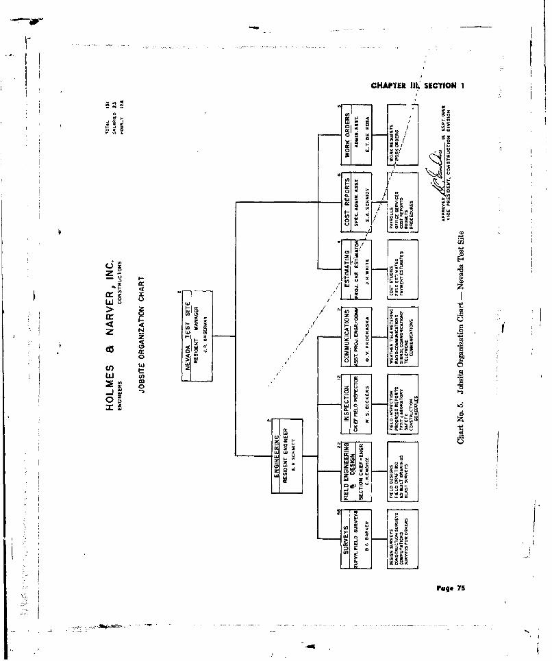
CI4APIE& lII SECTION 1
Lo
I0 w -
> 4>
9 OZ
w~' r
ow 2,
o RE
Ix r-,cr~~~ 9Cfw n 4,'oo '
4~t x -
24 I. , ~ '44 ~~~ I- NA
ILL 4,-~ 1'- ,s -.
z~ z-~
w~ 8 4
-
(0 4.
0 - La
di0 >L
Page 75
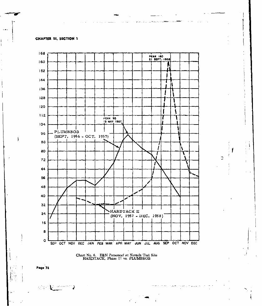
CHAPTER III, SECTION I
PrAK 40
160 - - - - - - -
12
112
104
(SEPT. 195 6 -OCT. 1957)-
- --0--
I t
64I56I
ARD)TACi<I24 (NOV. 1957 -DEC. 1958)
SEP OCT NOV DEC JAN FEB MAR' APF? MAY JUN JUL AUG SEP OCT NOV DEC
Chart No. 6. H-&N Personnel at Nevada Test SiteHARDTACK, Phase IY vs. PLUMBBOB
Page 76
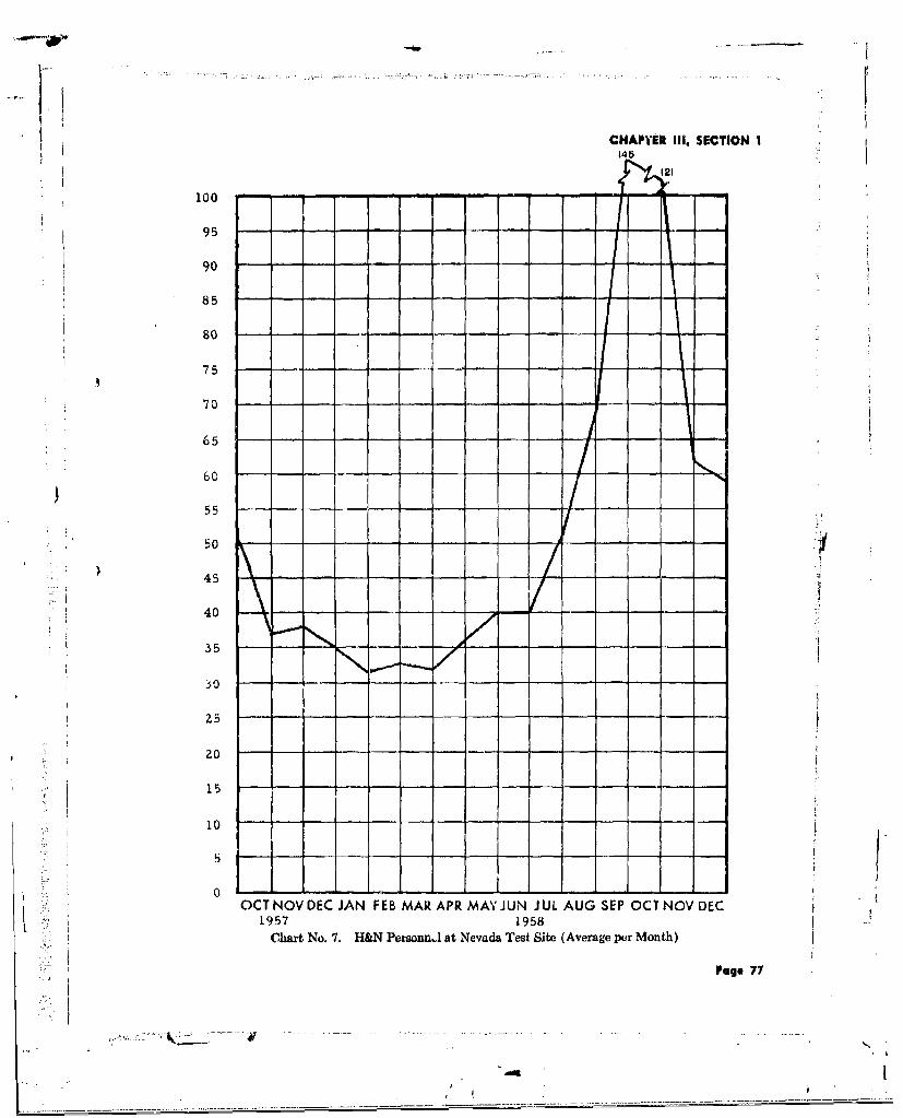
CHAPYER III, SECTION I145
121
100 - -- a- -
9- - - - -
90 --
85 -- - - ---
80 -- -
) 75-
65 --
60-
55--
50 - -
45 -
40-
35 - - - - - -
30--
25 - --
20
15
10
OCT NOV DEC JAN FEB MAR APR MAY JUN JUL AUG SEP OCT NOV DEC
1957 1958
Chart No. 7. H&N Persoal.m at Nevada Test Site (Average per Month)
Page 77

CHAPTER Il, SECTION I
and 1 tower, for a total of 20 events. The pro- on 19 September 1958, The extremely rapidgram was further revised and expanded to ulti- build-up of personnel to meet the Users' re.mately include a total of 37 events (6 vertical quirements, particularly in design and survey,holes, 11 balloons, 7 tunnels, 10 towers, and 3 created a difficult staffing problem. To overcomesurface), this problem many of the survey crew require-
ments were filled by EPG personnel surplusedMajor changes in the concept of the Fa)l after Operation HARDTACI, Phase 1. Los An.1958 Operation and the rapid expansion of the geles Office engineers on tepoary duty at
program required maximum coordination among Mercury provided the required design assistanceH&N, the Users, aiid AEC. In addition to the to theField Engineering Group.permanent liaison engineer maintained by H&Nat LRL, Livermore, additional liaison personnelwere assigned to temporary, duty at LRL and The rapid development of requirements andLASL to obtain advance information of plans fluctuating criteria for the Operation, encom-and criteria developed by the laboratories. As passing more events than any previous opera-planning developed and changed, Project man- tion at EPG or NTS in an equal period of time,agement personnel, and Project Engineers made created problems in liaison, coordination, andfrequent trips to the laboratories, NTS, and control, making it difficult to schedule construc-ALOO. tion progress. Particularly in Tunnel U-12b the
frequency and number of changes had consider-Close coordination was essential between able impact on design, survey, and inspection.
the H&N field staff and the CPFF and LumpSum construction contractors to ensure proper The many User agencies and the variedintrepretation of design and incorporation of types of construction and support services re-changes. quired for the tests also created coordination
A notable improvement in field inspection and control problems. To meet schedules andpractices during the Operation was made by re- to complete the Operation with appropriate re-quiring the majority of inspectors to be quali- cords necessitated frequent conferences, ade-fied engineers. These insnectors were able to quate dissemination of data, and adherence ofapprove, at the construction site, minor changes all User agencies to Standard Operating Pro-required by modified criteria or nonavailability cedures. However, the rapidity of design changesof materials, without the delays inherent in re- and the enlarged scope of the Operation resultedturning to the design engineers for concurrence, in some deviations from these essentials which
added to the complexity of design and construc-On 4 July 1958, there were 45 H&N person- tion coordination and the compilation of as-
nel at NrS, and a maximum of 160 was reached built records.
Page 73
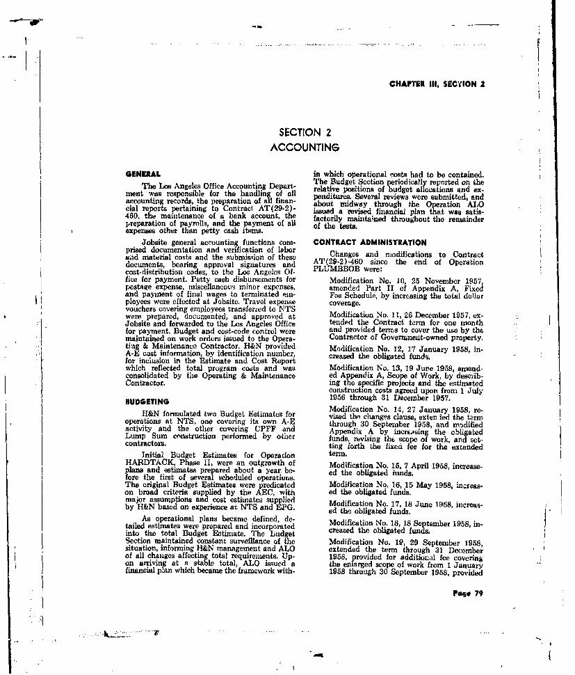
CHAPTER III. SECTION 2
SECTION 2ACCOUNTING
GENERAL in which operational costs had to be contained.The Los Angeles Office Accounting Depart- The Budget Section periodicaily reported on the
relative positions of budget alocations and ex-ment was responsible for the handling of all penditures. Several reviews were submitted, andaccounting records, the preparation of all finan- about midway through the Operation ALOcial reports pertaining to Contrac AT(29-2)- issued a revised financial plan that was satis-460, the maintenance of a bank account, the factorily maintained throughout the remainderpreparation of payrolls, and the payment of all of the teats.expenses other than petty cash items.
Jobsite general accounting functions corn- CONTRACT ADMINISTRATIONprised documentation and verification of laborand material costs and the submission of these Changes and modifications to Contractdocuments, bearing approval signatures and AT(29-2)-460 since the end of Operationcost.distribution codes, to the Los Angeles Of- PLUMBBOB were:fice for payment. Petty cash disbursements for Modification No. 10, 25 November 1957,postage expense, miscelaneous minor expenses, amended Part If of Appendix A, Fixedand payment of final wages to terminated in- Fee Schedule, by increasing the total dollarployees were effected at Jobsite. Travel expense coverage.vouchers covering employees transferred to NTSwere prepared, documented, and approved at Modification No. 11, 26 December 1957, ex-Jobsite and forwarded to the Los Angeles Office tended the Contract term for one monthfor payment. Budget and cost-code control were and provided terms to cover the use by themaintained on work orders issued to the Opera- Contractor of Government-owned property.ting & Maintenance Contractor. H&N provided Modification No. 12, 17 January 1958, in-A-E cost information, by identification number, creased the obligated funds.for inclusion in the Estimate and Cost Reportwhich reflected total program costs and was Modification No. 13, 19 June 1958, amend-consolidated by the Operating & Maintenance ed Appendix A, Scope of Work, by desciib-Contractor. ing the specific projects and the estimated
construction costs agreed upon from 1 JulyBUDGETING 1956 through 31 December 1957.
Modification No. 14, 27 January 1958, re-H&N formulated two Budget Estimates for vised the changes clause, extenled the term
operations at NTS, one covering its own A-E through 30 September 1958, and modifiedactivity and the other covering CPFF and Appendix A by increasing the obligatedLump Sum construction performed by other funds, revising thF scope of work, and set-contractors, ting forth the fixed fee for the extended
Initial Budget Estimates for Operation term.HARDTACK, Phase I, were an outgrowth of Modification No. 15, 7 April 1958, increase-plans and estimates prepared about a year. be- ed the obligated funds.fore the first of several scheduled operations,The original Budget Estimates were predicated Modification No. 16, 15 May 1958, increas-on broad criteria supplied by the AEC, with ed the obligated funds.major assumptions and cost estimates supplied Modification No. 17, 18 June 1958, increas-by H&N based on experience at NTS and EPG. ed the obligated funds. 9
As operational plans became defined, de- Modification No. 18, 18 September 1958, in-
tailed estimates were prepared and incorporated creased the obligated funds.into the total Budget Estimate. The LiidgetSection maintained constant surveillance of the Modification No. 19, 29 September 1958,situation, informing H&N management and ALO extended the term through 31 Decemberof all changes affecting total requirements. Up- 1958, provided for additional fee covering,on arriving at a stable total, ALO issued a the enlarged scope of work from 1 Januaryfinancial p!an which became the framework with- 1958 through 30 September 1958, provided
Page 79
c--
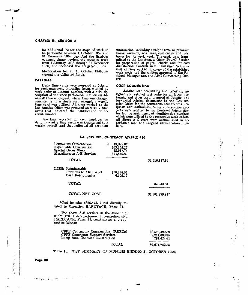
CHAPTER III, SECTION 2
for additional fee for the scope of work to information, including straight time or premiumbe performed between 1 October 1958 and hours, vacation, sick leave, cost codes, and total31 December 1958, modified the fixed-fee hours for the work week. The cards were trans-rayment clause, revised the scope of work mitted to the Los Angeles Office Payroll Sectionfrom 1 January 1958 through 31 December for preparation of payroll cheks and for cost1958, and increased the obligated funds. distribution. Controls were maihtained to ensure
that all time worked in excess of the establishedModification No. 20 13 October 1958, in- work week had the written approval of the Re-creased the obligated funds, sident Manager and the AEC Contracting Offi-
PAYROLLS cer.
Daily time cards were prepared at Jobsite COST ACCOUNTINGfor each employee, indicating hours worked bywork order or account number, with a brief de- Jobsite cost accounting and reporting as-scription of the work performed. For certain ad- signed and verified cost codes for all labor, ma-ministrative employee,, whose time was charged terials, and other costs incurred at Jobsite, andconsistently to a single cost account, a weekly forwarded related documents to the Los An-time card was utilized. All time worked at the geles Office for the permanent cost records, Re-Los Angeles Office was repoited on weekly time quests and authorizations for construction pro-cards that indicated the identification or ac- jects were referred to the Contract Administra.count number. tor for the amignment of identification numbers
which were affixed to the respective work orders.The time reported for each employee on All direct A-E costs were accumulated in ac-daily or weekly time cards was transcribed to a cordanco with the assigned identification num-weekly payroll card that indicated all pertinent hers.
A-E SERVICES, CONTRACT AT(29-2).460
Permanent Construction $ 49,022.07 4Expendable Construction 903,358.27Special Order Work 12,617.74Miscellaneous A-E Services 651,849.87
TOTAL $1,616,847.95
LESS: ReimbursableTransfers to AEC, ALO $28,838.87Cash Reimbursable 6,109.17
TOTAL 34,948.04
TOTAL NET COST $1,581,899.91*
*Cost includes $,R60,473.10 not directly re-lated to Operation HARDTACK, Phase I.
The above A-E services in the amount of$1,221,426.81 were performed in connection withHARDTACK, Phase II, construction and sup-port as follows:
CPFF Contractor Construction (REECo) $6,578,499.89CPFF Contractor Support Services 2,211,608.35Lump Sum Contract Construction 281,624.61
TOTAL $9,071,732.85
Table 11. COST SUMMARY (12 MONTHS ENDING 31 OCTOBER 1958)
Page 80

CHAPTER III, SECTIONS 2 and 3
The Los Angeles Oflice Accounting Section scientific programs and projects. Due to themaintained records of A-E costs under the accelerated program, only two Cost and Esti-major categories of Scientific Construction, Aux- mate Reports were issued, the 30 Septemberiliary Construction, Special Order Work, and 1958 preliminary report, and the 2 NovemberMiscellaneous Services. These costs were further 1958 final report.divided as direct engineering, indirect engineer- Table 11 presents a summary of costs foring, and general and administrative expense, the 12 months ending 31 October 1958.Labor distribution was summarized by identifi-cation number or appropriate account number AUDITINGfrom the information shown on the weekly timecards. Procurement of materials and services The major auditing functions at Jobsitewere authorized by purchase orders issued by included 1) the verification and reviaw of doc-the Los Angeles Office and were charged to the uments pertaining to costs reported by lumpproper accounts when received, sum contractors and thu related contract pay
estimates, 2) verification of invoices applicableFixed-price Contract costs, although deter- to purchase orders, and 3) audit of petty cashmined by the A-E, were not carried under Con- expenditures. Final pay estimates in the totaltract AT(29'2)-460, but were paid by the AEC amount of $281,624 61 for two constructionand transferred to the records of the Operating contracts executed by the AEC, were approved& Maintenance Contractor. Identification num- and submitted to AEC/ALO for payment.bers assigned by the Contract Administrator,as reflected on the approved work orders, were TELETYFEWRITER SERVICEalso used by the Operating & Maintenance Con-tractor for cost accumulation and reporting. Teletypewriter service was continuouslyReports of A-E costs and working estimates available between the Los Angeles Office andwere submitted to the Operating & Maintenance Jobsite throughout Operation HARDTACK,Contractor for incorporation in the consolida- Phase Ii. This system afforded a rapid meansted Cost and Estimate Report. Costs were identi- of exchanging correspondence, and improvedfied and reported by area, type of work, and by operational efficiency.
SECTION 3ESTIMATING
GENERAL 2. Preliminary and Budget Estimateswere made at the request of AEC toEstimating procedures and policies were determine the approximate cost of aformulated by the Corporate Chief Estimator. r ie ty. Primary Esti.Direct supervision of the Estimating Section in mates were usually incorporated inthe Los Angeles Office was provided by the Pro- ma w r psa ionject Chief Estimator, functioning under the Preliminary Proposals.Manager, Construction & Facilities. The Jobsite 3. Official Estimates for Lump Sum Con-Estimating Section was under the direction of tracts were prepared by the Los An-the Resident Manager. geles Office Estimating Departmentfrom approved drawings and the con-
ditions of the Invitations to Bid.Changes after the award of a lump sum
TYPES OF ESTIMATES contract were covered by Field ChangeOrders, with the estimates prepared atThe five types of estimates prepared and a NTS.
brief description of each type follows:
1. Cost Studies were made to compare 4. Official Estimates for CPFP Workvarious methods of construction, main- were prepared to cover estimated con.struction costs incurred by the Op-tenance, and operation. (Although a erating & Maintenance Contractor intotal of only 15 cost studies is shownin Table 12 - Cost Estimates Prepared support of approved work orders.- many more cost studieN were pre- 5. Estimates for A-E Services coveredpared to furnish the most economical various non-construction items, such asdesign for AEC requirements.) field surveys, feasibility studies, etc.
Page 81

CHAPTE9 111, SECTIONS 3 and 4
IMPROVED PROCEDURES tions, pre!i-ninary estimates of cost, proposedstarting and finishing dates, and proposed me-
A meeting regarding methods to improve thods of accomplishment.work coordination at NTS was attendte. byrepresentatives of the AEC, REECo, and h&N.To facilitate construction approvals it was agrecd LUMP SUM CONTRACTSthat estimates should he prepared by increments,as units of design were completed. The list of Each of the AEC/LVB lump nmm coatractH&N subaccount numbers for construction ca- bid openings was atterded by the Residenttegories was revised to meet the requirements of Manager, the Jobsite Project Chief Estimati,REECo. and the Los Angeles Office Project Chief Esti-
To comply with the provisions of Chapter mator. The two Project Chief Estimators check-To cmplywit theproisios o Chater ed the bids and prepared abstracts thaet were6106.06 of the AEC Manual, preliminary pro- used t evaluate the br ta'ds.posals were submitted to AEC for oIt PAC workin excess of $20,000. These proposals were pre- Table 12 shows the number and type ofpared in printed booklet form and included a estimates prepared during the period fromgeneral description of the work, justification of November 1957 through October 1958, togetherbasic need, preliminary plans, outline specifica- with net estimated costs.
TYPE NO. NE'i ESTIMATED COST
Cost Studies 15 $ 5,334,711Preliminary and Budget Estimates 30 3,167,993Official Estimates for Lump Sum Contracts 2 287,090
Official Estimates for CPFF Work 411 7,735,694
Estimates for A-E Services 3 33,327
Totals 461 $16,558,815
Table 12. COST ESTIMATES PREPARED
SECTION 4
WORK ORDERS
H&N was responsible for the preparation "0" WORFK ORDERS. The "O"-type Workand issuance of all work oiders, except those Order was issued to REECo for services re-applicable to Camp Mercury facilities. Work quested by participating test organizations, suchorder requests contained the project cost sym- as 1) advance procurement of material andhol, date of request, date rquired, work to be equipment to be used in the test facilities pro-performed, and site or station number. Requests gram, 2) warehousing scientific equipment, 3)were screened by the H&N Work Order Section providing transportation and long distance com-for duplication and accuracy. The Jobsite Cost murication services and 4) furnishing miscel-Reports Section assigned the proper job cate- laneous materials, supplies, and reproductiongory ("C," "FS," or "0"), and when required services. Cost estimates were not required forthe Estimating Section prepare( cost estimates, these work orders.All work orders were approved by AEC and were "FS" WORK ORDERS. The "FS"-typenormally distributed with drawings and esti-mates. Work Order was issued for field support work re-
quested by participating test organizations. ThisThe three types of work orders used are de- type of request did not require the preparation
fined below, of formal drawings for its accomplishment. It
Page 82

CHAPTER Ill, SECTION 4
LEGEND N360 d 1 --C .. . ..
v e a-J02-FS
320 ......... To 0if
300 TOTAL
i 240 '-------
0 220- ------ t
LI0
i 80 180- .... .
160 -____
,,- I
6 2 0 . - - - --4 ... -I ..... 1....-10 0 . .. .. . .;
° .... ... ... . ...... .- -- . ..... . . ........ . ... .. .. .,
NOV DEC. JAN. FEB. MAR APRIL MAY JUNE JULY AUG. SEPT. OCT NOV DEC.
Chart No. 8. Number of Work Ordcrs Per Month, Nov, 57 to Dcc. 58
Page 23
:1L-r

CHAPTER III, SECTION 4
440 .PLUMIBOB
420 - (NOV. 1956 - OCT. 1957) -
400j zs -
360 - ...... - -
340 -- - - --- -
320 -... . .I I300-- .- "
260 .. .I t_ _
240-- --
zoo - - -"
200 - --- - -
180 - -'-
160 - --
I140 - - - -- - 4-
20 --
/ \i80 . ..- /60 - -
40- "'- --o . -
20 H _ -ARDTACKI11
0 1 1 I I I I .NOV VEC JAN FEB MAR APR MAY JUN JUL AUG SEP OCT NOV DEC
Chart No. 9. Number of Work Orders Por MonthHARDTACK, Phase II vs. PLUMBBOB
Page 84

CHAPTER III, SECTIONS 4 and 5
covered 1) labor and equipment support, 2) in- a comparable two-week period. These blanket-stallation of scientific equipment and materials, type work orders were written to cover the in-3) minor electrical, mechanical, and iron work, dividual Users' field requirements, as requested4) decontamination, 5) recovery of scientific by "buck slips."equipment, 6) minor rehabilitation of scientificfacilities, and 7) preparation for test events "C" WORK ORDERS. "C"type WorkH&N prepared detailed estimates, assigned iden: Orders, issued to authorize construction for whichtification numbers, and reported progress on engineering and design were perormed by H&Nthere work orders. under Job I of the contract, were assigned con-
tractual identification numbers by the H&N Con-During the period of peak activity, the tract Administrator. The "C"-type, initiated by
AEC, Scientific Users, H&N, and REECo agreed an authorized User or an H&N Jobsite Engineer-to the issuance of blanket-type work orders ing representative, covered the construction ofwhich were effective for a two-week period. The scientific stations, roads, technical support struc-estimated costs were based upon an analysis of tures, scientific shop and trailer areas, andPLUMBBOB costs for "FS"-type services over power, coax, signal, and communications systems.
SECTION 5PERSONNEL AND SECURITY
GENERAL Early in Spring 1958, it became necessary too& Security btain the services of mining engineers and geolo-
The H&N Corporate Personnel Sgists with extensive tunnel experience. Short-Department provided all industrial relations and ly after 1 May 1958, a small number of inspec-security support for the AEC Facilities Pro- tors and survey personnel were requisitioned.i et Group, Close coordination between these Simultaneously, the Employment Section wastwo offices in matters pertaining to policies, per- alerted that a build-up in personnel strength of .4sonnel standards, and manpower requirements H&N forces at NTS could be expected. Essen-resulted in fulfilling satislactorily all ABC Fa- tially this increase in personnel requirements in-cilities Project personnel and security require- volved surveyors, and initial requisitions werements. Although there was no direct organiza- filled by former EPG employees; however, astional relationship between the Corporate Per. the build-up demands accelerated, it was neces-sonnel & Security Department and the AEC sary to supplement the EPG rehires through theFacilities Project, the former group furnished International Union of Operating Engineers incertain services, including personnel recruitment Las Vegas. By 19 September 1958, 104 surveyand processing, insurance activities, monitoring parsonnel were assigned to NTS.of AEC security policies, personnel relations,and travel arrangements. The Corporate Per- SECURITYsonnel & Security Department was directed bythe Manager, Personnel & Security, with theaid of Assistant Managers and Section Super- ances were prepared at Jobsite and the Los An-visors. These sections included Employment, geles Office. All requests for clearances werePersonnel Relations, Security, and Clerical & processed through the Los Angelns Office toTravel. H&N Personnel & Security representa- ALOO. Whenever a cleared H&N employee wastives were not assigned to NTS; therefore, the permanently transferred to NTS, extension ofrequired personnel and security affairs were the employee's clearance to include NTS washandled by the Special Administrative Assistant, accomplishd by a letter to the on-site ABCJobsite, under the technical direction of the Cor- security representative, with a carbon copy toporate Personnel & Security Department Section ALOO.Supervisors. Permanent or temporary security badges,
authorizing access to the various areas at NTS,EMPLOYMENT were issued by the NTS Badge Office in re-ponse to a written requesL by the H&N Resident
Emlyment activities for NTS ended with pnet rte eus yte1INRsdnEmplo et Manager. Temporary badges for uncleared par-the close of Operation PLUMBBOB in October sonnel were issued only if security processing1957. H&N population at NTS steadily decreas- had begun.ed throughout the balance of 1957. and by theend of the year a staff of only 35 persons was Security representatives of H&N and AECassigned. A number of the persons affected by attended frequent conferences on classificationthis population decrease were absorbed by either and other security matters to deal with urgenciesthe Los Angeles Office or EPG. of the accelerated program.
Page 8 - 86

APPENDIX
APPENDIXGeneral Site Plan - Nevada 'rest SiteArea 3 - LayoutArea 5 - General Layout
Area 5 - Detail Layout - Sheet I of 2Area 5 - Detail Layout - Sheet 2 of 2Area 7.- Layout
Area 8 - LayoutArea 9 - Layout
Area 12 - Layout
U-12b Tunnel ComplexU-12c and U-12f Tunnel ComplexesU-12e Tunnel Complex
Page 87 -as
4?b

APP914DOX
0 _o
0F
Al0CE ot
cw ou~f OM 0
0 3- 3- U
BI.M
WILL M 3 wag eows3
P-41 s
6CALIr IN FEET0 *,DOD C 000 0
Fiture No. 33. General Site Plan -Nevada Test Site Page 89 - 90

APPENDIX
4B 2
RALM Zp DYE.2
F u wo MIH AYlT --
MA A A
MW"O MINDJ 0Door 001
GR~APHIC SCALE
SITE PLAN-
~I0WES II NARVS IWC - -

1" 0.9 .
ACPI4DQ
-pI _ 0 O 0 l 4 /r
IV= -4 *C 370IC
Wk 2P _
MAI
B:902 'A to-. 9NC 34/A5/A/Ct
7 536.40 J5O. d ,6.~6 D 33
a.104 -T /C. - *..
EI-4 f1-v '. 6
90,/ ,
Figure No, 34. Area 3 Layuut Page 91 -92

APPENDIX
-7''
_ _ _ tvi7/ /a
6/t
55.14U/. D,817
U../ S.AOI-.SMYCOMSO
550. 002 -- 3
350/s 840/
Page91-9
.1/,7 \~ .-

APPENDIX
*R
/Figure No. 35. Area 5 - cneral Layout Page 93 - 94
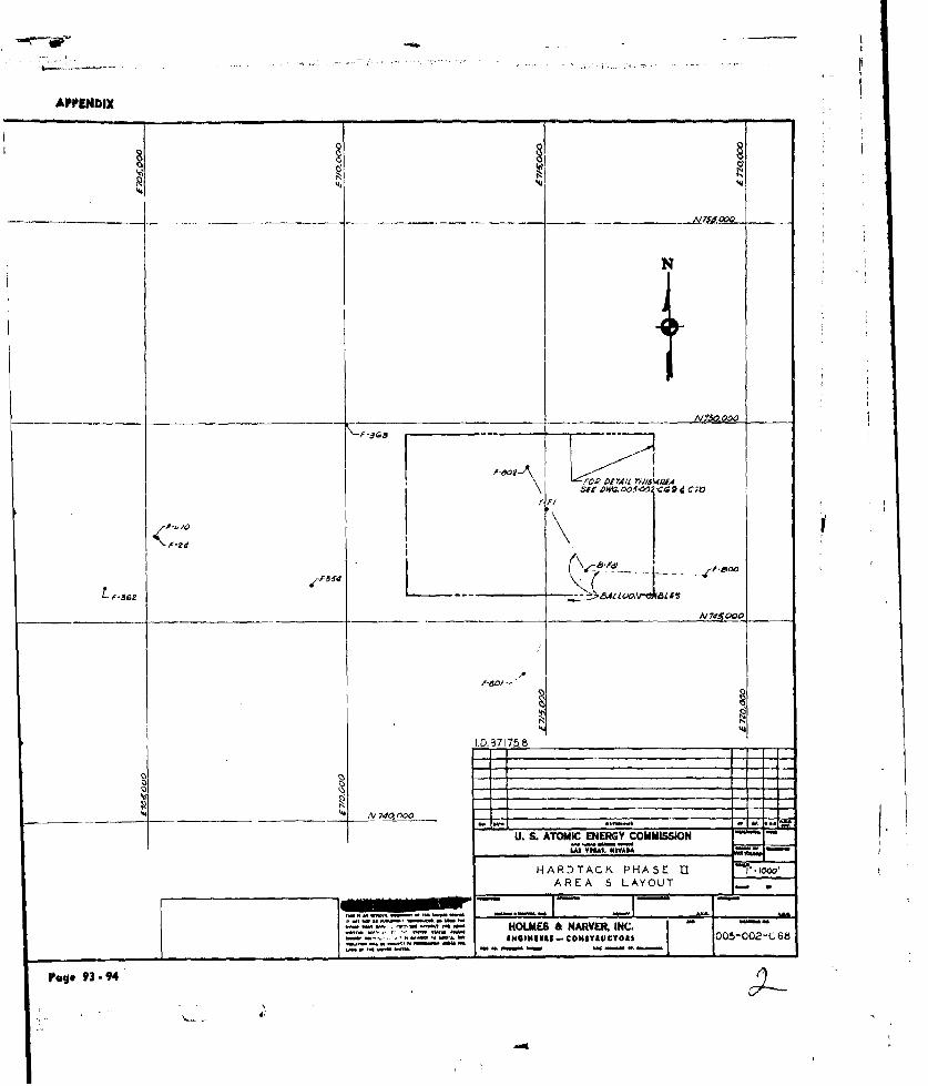
APPENDIX
" e lo#c. 00,".c
N N
./ NA'. Oo
'F I
Zdd
I. Q. 87175 8
HARDTACK PHASE " -i
AREA 5 LAYOUT
HOLMES & NARVEK. INC. "'l WG~wIN145- C0Wl'VCTO$ 005-002-C 68
P g 9 3---9 4
_______________ ______ ____ A?~OO ___
~*d6~*'*
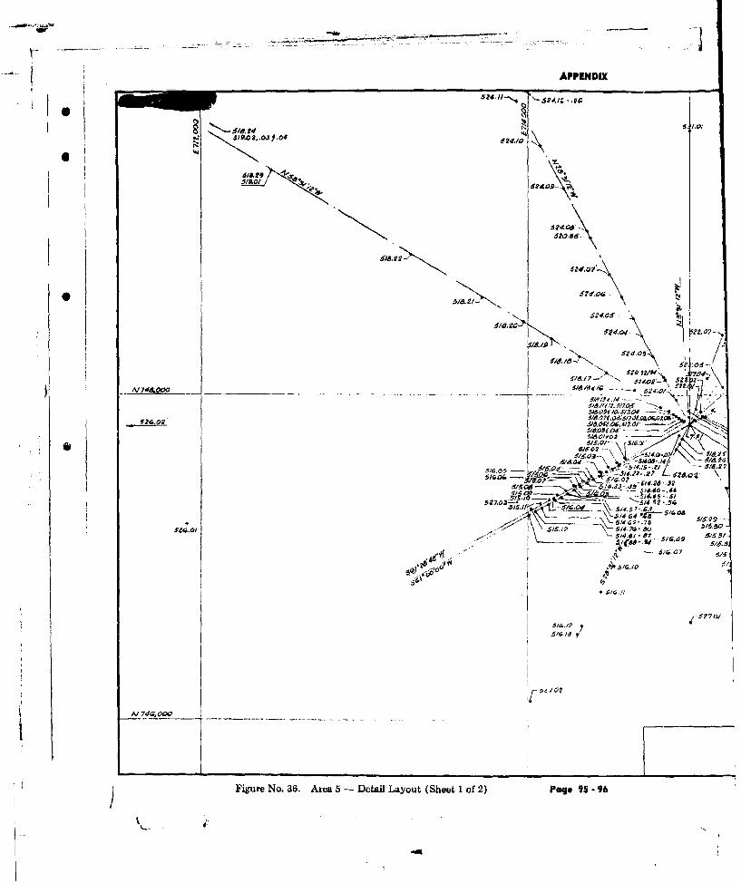
APPENDIX
~,aog,.oJoS242405
4.
524,02 IS.07e I' , 0
d2O.6/O.
6-/1..2
5524.0
sm7 74& 000 5/4./
*o 7
// 74,9 0 0
Figue No 36.Area5 - etai Layut (beet1 of2) Pgo 9 - 9

APPENDIX
'-412-2
AV' .i.0
--- 42 964--
42'
52.07 6109 15k /t
V 647 4.2621559~10,4'Z04 <4
r2 010 -1.0/I
52~~~524 7 2/W2G4,WA
ARE 5 /AOUT
514.SJ-.Js 6,440-44os 05-02 C
Pag 5i.5-6 9 -9631
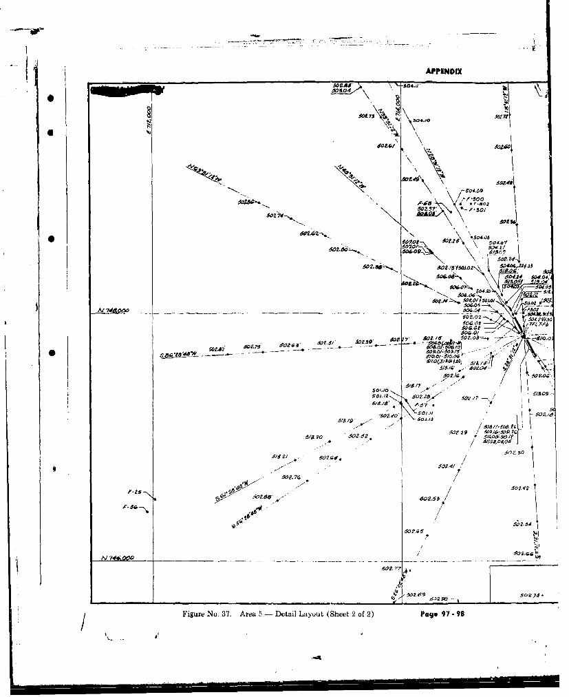
APPENDIX
iota,
O~t 7 i"
t '4. ,
An.. .\2-
•~~~gp 2". -f \ -'.5/f
Al 7440<W OZ3 - -,
N 40606-
'00
9, ot. 5 52 30.\ 2/52. -
s 64.'m
Me .od - "
.:17' 1 ".7 '
64,2 56 . ,'' -I\ .z sot 2 9 01, -SP
Al z 130"" i
60?0G.77
Figure, .€o .m t, ,
50 0P 0.I . oz,-, 13 - . O."Q
- ,'160.2, $0.
5/2 525 529 / 0/ 5 o2,7?
A ' ./ . 9 - / .. o~o
Figur No,37. rea -- etai Layut (heet2 of2) Pge 9 - 0
.6/52/,

APPENDIX
grog., SI 91
itA~-oo44 10,11
P-GN
do .6 i* .340
50409 so P/ 1a7
504 2 /
.506.01
02./~5Z 2. 7' 510-07/
*2 5O~~\\ F604td 0~04 0.04, A 0
-4---. /P
dwzj, ~ ~ ~ 502067 1A0
2 / - 4- /a i o? a -*
/40 f4 , 14~d
6060 O16,40p5
oe~
L0I 42MA 502.
ARE5A 5 LAYOUT r\2
400
Page -97 -

APPENDIX
'4'4
Am /6,C0
0*d AWAAr-
7'O~ 70.6 7-2I MA0O
7t 0 "1:-.~
7,,
J.,.
70*2'
FigreNo 38 Aea7 Lyot ale9900
-04 0

APPENDIX
/0130
7- 6302
~-7-301 704,07__
- 7- 24, 706.01/S71.01"
'04
-u -s.-.___o_-.---N-.--co-- - _ __ o __" --__-_l
'45/- COM A R AP14'0 O JA4.
7044.6 - o **Vuto, 0 00SU. S. ATOMIC ENERGY COMMISSIN
13 ARDTACK PHA5E flIrio70G.~'%4 AREA 7 LAYOUT-
"~ -c--~'-~ - MOVES & NARVER INC.UHNsalsS- CONSTRUCTORS 007-0O2C4~
Page 99. 100

APPINWX
1I
-- - ~---------~-~-----.------ -- --
S
I !;ea
~> I / ~
- N~&OOO ___________________________ / -~
/
Na~OoO - -
/U
00I'
_______ __________ _________ I.J
PigLire No. 39. Area S Layout Pug~ gOl 102
.1'

APP9ND1X
HADTC PHS 0
AREA 8LAYOU
HOME &VAVkICsw/Hls-ckruvos08 0
-ag .'--- -10
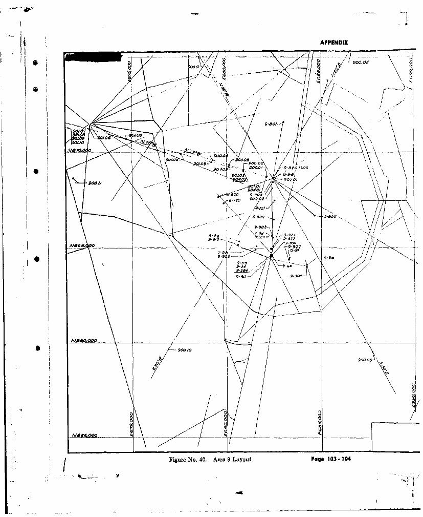
- APP9ENWX
W / 900.0
9.80J
q 9 -0
90900.09
Fiur No 404ra9LyutPg-0 0

APPENDIX
'N..
HADTC PHA5 I] _
/~~AE 9 LAYOUT-~---
____l~&S CN3lCTl 00,1 _ ___ _ _ _ _ __ _A/-00 r2
Pago 103-104

APPENDIX
6~N,
-, 1,3
IWI1
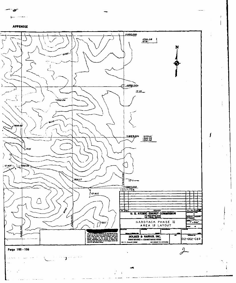
APPENDIX
AAA'9A-
irN
77744
___ '000a
lily>. I.ua 0,0,00--
-- .- -U. S. AOMIC ECNEM COMISSO
Page 10 -106

APPENDIX
AO*I~~co ~ /S ux1
Mr~/ A/~S~'.4 C V \ <$
AM I1~jAlca 117
4.0,1t didk
P io040 7.f
A11M1tP *I
VOJ;*A/Oil V/
41C ccve
Mah"Is
Figure No. 42. U-12b Tunnel Comiplex Pug* 107.- 108
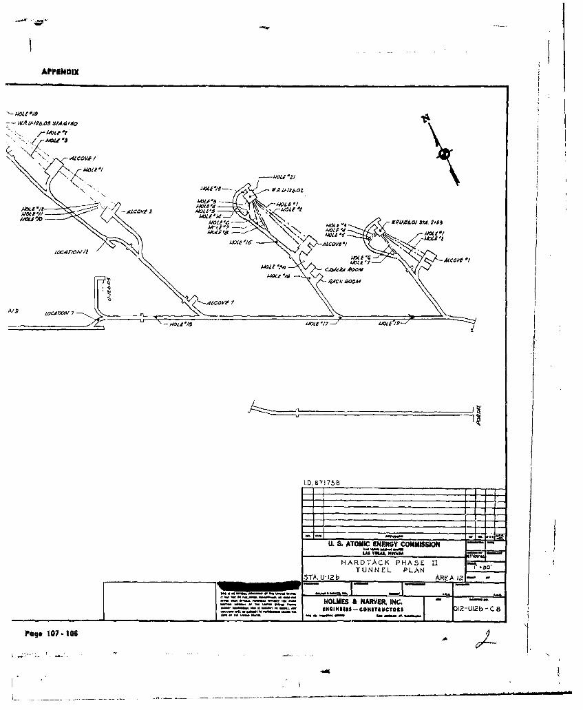
APPINDnX
WA41I1PO0 SM.4000
W--
-4OV02 'wo
-ALOVw -AOV.0
Iva -0 moil~ 14 ERWO M 98hFcAeI'6 -,1
IX4T, A' ~ ALC VA /ACU'Awl A 16 A ~ N1
- 4dC 'O A 1 CO"o
-v Ila --
U. SATOMIC ENEMGY COMMISSION
HARDTACK PHASE U -
TUNNEL PLANSTA.U-12 b AREA 2-
- - rn~a ~ - - HOLMES A NARVER, INC.IHImaEls - COubIitBuCToa i2-Ui2b -C 8
Page 107- I as
4"I

r APPENOIX
0%
ciq
Figue N. 43 U-2c nd U12fTunel CmplxesPage109 11
LAt~2O

APPEN4DIX
IVI

Figure~ No. 44. IJ-12e Tunne &Iowpex 111-112
I #A% 40D*

U. S.ATOMIC'ENERGY COMMISSom
HARDTACK PHASE 11
TAUIR-TUNNEL PLAN - Rkc2.
m~ - - -eNE~iumI-CONTSUC~a L-Uize- CI2