physical aging effects on the compressive linear ... · physical aging effects on the compressive...
TRANSCRIPT

NASA Technical Memorandum 110224
/ / ....
_SY;i _ -
/
Physical Aging Effects on theCompressive Linear Viscoelastic Creep ofIM7/K3B Composite
David R. Veazie and Thomas S. Gates
Langley Research Center, Hampton, Virginia
December 1995
National Aeronautics and
Space AdministrationLangley Research Center
Hampton, Virginia 23681-0001
https://ntrs.nasa.gov/search.jsp?R=19960014851 2018-07-18T08:41:55+00:00Z


ABSTRACT -- An experimental study was undertaken to establish the viscoelastic behavior of IM7/K3B
composite in compression at elevated temperature. Creep compliance, strain recovery and the effects of
physical aging on the time dependent response was measured for uniaxial loading at several isothermal
conditions below the glass transition temperature (T). The IMT/K3B composite is a graphite reinforced
thermoplastic polyimide with a T of approximately 240°C. In a composite, the two matrix dominated
compliance terms associated with time dependent behavior occur in the transverse and shear directions.
Linear viscoelasticity was used to characterize the creep/recovery behavior and superposition techniques
were used to establish the physical aging related material constants. Creep strain was converted to
compliance and measured as a function of test time and aging time. Results included creep compliance
master curves, physical aging shift factors and shift rates. The description of the unique experimental
techniques required for compressive testing is also given.

Introduction
Advanced polymer matrix composites (PMC's) are desirable for structural materials in
diverse applications such as aircraft, civil infrastructure and biomedical implants because of their
improved strength-to-weight and stiffness-to-weight ratios. The development of analytical and
experimental tools to aid in the study of composite durability is the impetus for intensive design
and development studies at NASA and major industry based airframe developers [1].
A possible disadvantage of polymer-based composites is that the physical and mechanical
properties of the matrix often change significantly over time due to exposure to elevated
temperatures and environmental factors. This problem has resulted in an extensive research
initiative to develop comprehensive material property characterization techniques and analytical
modeling methods aimed at predicting the long term mechanical response of polymer matrix
composites at elevated temperatures. The ultimate goal is to develop accurate analytical models
and accelerated test methods needed to engineer advanced polymer matrix composites to ensure
long-term structural integrity over the design life-time.
This paper presents unique experimental techniques and apparatus used to measure the
viscoelastic behavior of PMC's in compression at elevated temperatures. Isothermal, constant
load, creep compliance measurements were performed on the matrix dominated transverse and in-
plane shear behavior of IM7/K3B in compression. Linear viscoelasticity was used to characterize
the creep and superposition techniques were used to establish the physical aging related material
constants. The resulting creep compliance master curves, physical aging shift factors and shift
rates can be used as input data to a viscoelastic creep compliance procedure to establish time
dependent behavior and predict long term response. The observed differences in the time
2

dependentbehaviorin the transverseand in-planesheardirectionsalong with the effects of
elevatedtemperaturearediscussed.
Physical Aging Characterization
The main focus of this research is one aspect of long-term polymer matrix composite
viscoelastic behavior: physical aging. Physical aging is a process, occurring below the glass
transition temperature (Tg), where the macromolecules gradually change their packing in order to
approach the equilibrium free volume state [2]. The gradual approach towards equilibrium affects
the mechanical properties of the polymer, often resulting in a material that is stiffer and more
brittle, so that the compliance is decreased (or the modulus increased) over what one would have
expected in a viscoelastic material without aging. In terms of free volume theory, one can
visualize that as the free volume decreases towards its equilibrium values, the mobility of chain
segments is hindered, giving rise to a stiffer response. Aging is a characteristic of the glassy state
and is found in all polymer glasses, as thoroughly documented by Struik [3]. The effects of
physical aging continue until the material reaches volume equilibrium. The time required to reach
volume equilibrium depends on the aging temperature. During this time the mechanical properties
may change significantly [4,5].
Several experimental studies have illustrated that the matrix dominated composite properties
of continuous fiber reinforced PMC's, namely the shear and transverse response, are affected by
physical aging in a manner similar to pure polymers [4,5,6,7]. Struik [3] showed that it was
possible to isolate the physical aging process in polymers from other behaviors by performing
isothermal creep compliance tests and using superposition techniques to establish the aging

related material constants. An illustration of the creep and recovery tests for determining aging
effects is shown in Figure 1. In these tests, the specimen is initially quenched from above Tg to a
temperature below Tg. The time the material exists below its glass transition is referred to as the
aging time, te. AS aging time progresses, a series of short (in comparison to the elapsed aging
time) creep segments of duration t_ are run to extract the momentary creep compliance of the
material. In this figure, the compressive (negative) strain is shown in the first quadrant (positive)
for reader clarity. Throughout this study, negative strain was converted to positive strain for use
in existing data reduction routines that were created for positive strain. The momentary creep
compliance of the material, S(t), can be described with a three parameter fit model, first
proposed for linear viscoelastic glass by Kohlrausch [8],
S(t)=Soe ('/_)" (i)
where S o is the initial compliance, 13 is a curve shape parameter, t is time, and x is the relaxation
time.
In nearly all cases of aging of polymers and PMC's, it is possible to bring the momentary
creep curves measured at different aging times into superposition through a horizontal shift. This
result is akin to the well known time-temperature superposition principle [9]. The aging time shift
factor, a,,, is defined as the horizontal distance required to shift a compliance curve to coincide
with a reference compliance curve. If the aging time shift factor is plotted as a function of aging
time on a double-log scale, it is found to map a straight line with a slope of g. The shift rate, la,
4

d(loga,.)- (2)
d(logt,)
usually has values on the order of unity and can be considered to be a material constant. Thus, a
series of creep and recovery tests (as in Figure 1) can be used to experimentally determine the
value of the shift rate, g, for any given material.
Since the momentary creep curves collapse through horizontal shifting on the log scale, the
only parameter which changes as a function of aging time is the relaxation time. The momentary
material properties must then vary with aging time according to
S(t)=Soe ('/+'))_ , (3)
where
"C(te) ="C(telrefl)/a,, , (4)
t, tr,/) is the reference aging time, a,,),,/, = 1 and the shift factor is defined as
at. =( telreil l_. (5)
Thus to describe the momentary creep compliance at any aging time, the parameters needed are
the initial compliance S,,, the curve shape parameter 13, the shift rate g, and the relaxation time "c
at a reference aging time t_t,,i1 [1].
It is the intent of this work to establish unique experimental techniques to accurately measure
the compressive creep strain and recovery strain as a function of test time and aging time for the
5

time dependent response of fiber reinforced polyimide composites. Resulting compressive creep
compliance master curves, physical aging shift factors and shift rates for inclusion in Struik's
effective time theory are used to model the physical aging effects in the composite.
Test Materials and Specimen Configuration
The material system chosen for this study was a continuous carbon fiber reinforced
thermoplastic polyimide fabricated by DuPont and designated IM7/K3B. The fiber, IM7, was an
intermediate modulus carbon fiber manufactured by Hercules. The unaged T_ in the composite as
measured by Dynamic Mechanical Analyzer (DMA) G"peak was 240°C. Change in the T_ from
the unaged condition over extended aging times was measured by industrial studies and found to
remain within 3°C over 10,000 hours of isothermal aging at 170°C [10]. For this study, it was
therefore assumed that chemical aging of the composite would not occur and the T_ would remain
constant over the duration of the tests.
Rectangular test specimens similar to those described in ASTM Specification D3039-76
measuring 20.32 cm. by 2.54 cm., and consisting of 12 or 8 plys of approximately 0.0135 cm.
thickness, were cut from laminated panels. The in-plane transverse ($22) and in-plane shear ($66)
creep compliance data came from unidirectional 12-ply [90]t2 and angle-ply 8-ply [+4512_
specimens, respectively, where the subscripts 22 and 66 represent, respectively, the material
coordinate perpendicular to the fiber and the shear directions. Test were not conducted to
determine the other compliance components (S_t, S_2) due to their time-independent behavior.
Three replicates were used at each test temperature. Although all the specimens came from the
same material lot, many of the replicate specimens were cut from different panels.

TestEquipment
All of the creeptestswereperformedin convectionovensequippedwith digital controllers.
Copper-constantan(ANSI symbol "T") thermocoupleslocatednear the test sectionprovided
feedbackfor the oven controllerandwere usedwith a scanningthermocouplethermometerto
monitor the test temperatures.Thermal apparent strain was corrected for by using the
compensatinggagetechnique[11]. A diagram of the experimental setup is shown in Figure 2.
A uniaxial constant load was applied through a dead-weight cantilever arm tester that reacted
at a point outside the test chamber. A unique apparatus shown in Figure 3 was constructed to
allow a tensile creep test frame to be used for application of a compressive load. The compressive
creep apparatus consisted of two rigid frames connected by steel rods running through linear
bearings. The apparatus was designed such that the two frames could move in-plane relative to
each other when a tensile load was applied. To minimize friction between the contacting surfaces,
the steel rods were polished smooth and the linear bearings were lubricated with heat-resistant dry
graphite lubricant.
The specimen was positioned in the center of the apparatus and end loaded by the
convergence of the two inner rigid fixtures. Lightweight grips incorporating straight saw tooth
faces were fixed to the specimen ends to prevent slipping. Each grip consisted of two halves held
together by pins for accurate alignment. The contact surfaces between the grip ends and the rigid
fixtures were precision ground to transfer the load uniformly to the specimen. The gripped
specimen was held in alignment by small pins attached to brackets mounted on the inner rigid
fixtures.

To ensurestable compression,the specimenwas supported from column buckling by
lightweightknife edgeguidesasshownin figure 4. The guideswere mountedon the specimen
howeversincetheydid not connectto the grips,theydid not carryanyof the appliedaxial load.
The knife bladeswere easilyadjustableto allow for minimalcontactwith the specimensurface
andvariousspecimenthickness.Columnbucklingwascheckedduring loadingby longitudinally
alignedback-to-backstraingages,which would show a lack of parity in strain if simple bending
occurred. A sample plot of the strain parity from back-to-back strain gages is shown in Figure 5.
During the unloaded or recovery segments, the two inner rigid fixtures were separated from
the specimen grips by applying a slight compressive force from the creep frame lever arm. This
recovery procedure, however, left the lightweight upper grip and the knife edge guides to remain
fixed to the specimen and possibly hinder complete strain recovery. In order to verify whether or
not the weight of the upper grip and the knife edge guides had an effect on complete recovery, a
benchmark run was performed for the case of an unloaded specimen at test temperature. The run
showed that the lightweight upper grip and the knife edge guides had no effect on the creep or
recovery strain on the specimen. This unloading process therefore provided for virtually
unconstrained recovery while allowing the test chamber to remain closed during the entire test
sequence.
Strain in the gage section was measured with high temperature foil strain gages applied in the
center of the specimen. Micro-Measurement WK-000-250BG-350 gages bonded with the M-
Bond 600 gage adhesive and 220°C solder were used. The M-Bond 600 was cured at 120°C for
two hours. This combination of gage and adhesive seemed to minimize the problems associated
with coefficient of thermal expansion (CTE) mismatch to the composite and gage/adhesive creep.
8

Proper selectionof this gage type and adhesive gave CTE match and stability at elevated
temperatures.
Stress was calculated based upon the applied load and the specimen cross-section before
testing. For the [90]_2 specimens, the average measurement of two back-to-back gages, aligned
longitudinally, was used to compute ($22). For the [ +_45 ]2s specimens, the average measurement
in each direction of four gages, two back-to-back aligned longitudinally and two back-to-back
aligned transversely was used to compute ($66). The compliance terms used in data reduction for
these specimens are given as
(6)
$66(t) = 2e.x(t)[1-ey(t)/e_(t)], (7)(_Jf
where _ _ and e _ is the stress and strain in the loading direction, respectively, and e y is the strain
perpendicular to the load. Each gage formed a quarter-bridge circuit. Thermal strain
compensation was accomplished during data reduction. Commercially available instrumentation
provided bridge completion, excitation and signal conditioning. A personal computer equipped
with a 12-bit A/D board converted and stored the high level analog output signal from the
amplifiers.
Prior to testing, all specimens were dried for at least 24 hours at 110°C in a convection oven.
Immediately after drying, the strain gage adhesive installation was subjected to a postcure
segment by heating to 230°C for two hours. Following the postcure, the specimens were stored

insidea desiccatoruntil the gageswere actuallywired at the start of testing. After eachtest
sequencethespecimenswerevisually inspectedfor matrixcracksalongtheiredgeswith anoptical
microscope.Theseinspectionsrevealednoapparentdamageafterthesequencedtests.
Experimental Procedures and Data Reduction
To explore the effects of physical aging on the creep properties, a well documented technique
that measures the creep compliance as described in Struik [3] and depicted in Figure 1, was used
for all tests. This procedure consisted of a sequence of creep and recovery tests using a constant
applied load while the specimen isothermally ages.
All of the tests were conducted under isothermal conditions using monotonic compressive
loads. The test temperatures selected for the study were 200 °, 208 °, 215 °, 220 °, 225 °, and 230°C.
These test temperatures actually exceed the expected use temperatures of the material, however
they were selected to ensure that measurable aging occurred within the test period.
To ensure that all test specimens start the test sequence in the same unaged condition, a
means of rejuvenating the specimen was required. Rejuvenation was accomplished by a procedure
based upon work by Struik [3] and others who showed that physical aging is thermoreversible and
the excursion above T_ prior to quenching effectively rejuvenates the material. In the current tests,
the gauged specimen was heated to 250°C (10°C above T_) for 30 minutes immediately before the
start of any physical aging test sequence. During this period above T_ the material is more
compliant than in its glassy state. Consequently, a support bar was fastened between the upper
and lower grips of the vertically positioned specimen to prevent any shape alteration that might be
10

causedby the weightof theuppergrip or theknifeedgeguidesduringrejuvenation.This support
waseasilyremovedfollowing rejuvenation.
The method used to quenchspecimensfrom above Tg to the aging temperature varies
between investigators, such as using liquid nitrogen or submersing in an ice-water bath [ 12,13]. A
procedure by Sullivan [4] which utilized high-pressure air to quench the specimen was adopted
for use in this study. This method provided the only practical means to quench the material when
strain gages and wires are attached to the specimen. After reaching the test temperature during
this rapid quench, the material is in an unaged condition and the aging time clock can be started.
Temperature stabilization after quenching typically took less than three minutes.
The duration of each creep segment was 1/10th the duration of the prior total aging time. The
aging times (time after quench) selected for starting each creep segment were 2, 4, 10, 24, 48, 72
and 96 hours. After each creep segment, the specimen was unloaded and allowed to recover until
the start of the next creep test. To facilitate recovery, the specimen remained in the convection
oven at temperature while being unloaded. The recovery times were long enough to allow for
nearly complete strain recovery. However, to account for any remaining residual strain due to a
lack of complete recovery, the strain measured in the creep segment was corrected by subtracting
the extrapolated recovery strain from the prior creep curve.
For the creep tests, an applied stress level was chosen for each layup and used at all
temperatures. Determination of the applied stress level within the linear viscoelastic range was
made by checking that both Boltzman's superposition and proportionality conditions would be
met at the highest temperature for a given layup. Given an initial state of stress cy' applied for a
11

time t and an additional stress t_"applied at time t,, Boltzman's superposition principle [9] states
that:
E[G'(t) + O"(t--t,)]= E[G'(t)] + e[_"(t-- t,)]. (8)
Therefore, Equation 8 implies that given creep data,
prediction of the subsequent recovery period so that
superposition would allow the exact
_(t- tl) = G{S(t)- S(t-t,)}, (9)
where t_ is the constant stress, t, is the time of load removal, and S(t) is the creep compliance
function. Compressive creep and creep/recovery data provided data for checking superposition.
Proportionality states that for an applied stress ty, the strain in a material at any other stress is
found using:
e[ cG(t)] = cE[ cr(t)] where c = constant. (10)
A proportionality check was performed by plotting isothermal, creep compliance versus test time
for a specimen that was repeatedly rejuvenated, quenched and loaded at various stress levels. The
supposed transition from linear to nonlinear behavior would be evident by the vertical separation
of the compliance curves with increasing stress. These checks were made at the lowest and
highest test temperatures thereby ensuring that the effects of applied stress were minimized for all
temperatures and a linear assumption could be used in any model with assurance of reasonable
accuracy.
12

Figure 6 providesan exampleof the curve fits usedto characterizeeachsequencedcreep
compliancecurve. The momentarysequencedcreep/agingcurves were collapsedthrough a
horizontal(time) shift usingthelongestagingtimecurveasthe referencecurve.Figure7 shows
the collapsedcurve from the datashownin Figure6. In somecases,smallvertical (compliance)
shifts(ascomparedto thehorizontalshiftsin termsof thedouble-logscaleplots)werealsoused
in reduction of the IM7/K3B data. The sets of both horizontal shiftedcollapseddata and
horizontalandvertical shiftedcollapseddata,known asmomentarymastercurves,were fit with
Equation1.Theparametersfrom this fit weretermedthemomentarymastercurveparametersfor
agiventemperature.
Thetimeshifts(log a) used to collapse the sequenced curves shown in Figure 6 were plotted
versus log aging time and approximated through a linear fit, as shown in Figure 8. The slope of
this shift factor versus aging time data is the shift rate _t.
Results and Discussion
The range of linear viscoelastic behavior was experimentally determined to satisfy the
conditions of proportionality. Experiments were also conducted to assure that the linear
Boltzman's superposition condition was met for all tests. Using the test and data reduction
procedures outlined above, the short term sequenced creep compliance data for IM7/K3B was
found as a function of aging time over a range of five temperatures. Isothermal momentary master
curves for the transverse ($22) and shear (S66)terms were generated to show the temperature
dependency of short term creep compliance and the directional dependency of the PMC.
13

To evaluate the proportionality criteria, creep tests were run at 230°C and 225°C,
representingthe maximum test temperaturesused for transverseand shear compliance
respectively.The appliedstresslevelswerebetween3.56MPaand 1.81MPa for the transverse
complianceproportionalitytestsandbetween8.34MPaand5.59MPa for theshearcompliance
proportionalitytests.Coincidenceof the transversecompliancecurvesin Figure9 andthe shear
compliancecurvesin Figure 10 indicatedthat thedifferent stresslevelscausedlittle variationin
complianceon the log scalealthoughtherewassomesmalltrend in locationof the curvesin
relationto the appliedstress.Basedupontheseresultsandthe fact that the sameappliedstress
levelwasto beusedatall temperatures,proportionalitywasmetfor all tests.
The strainhistoryof a typicalcreep/recoverysequencefor a [ + 45 ]2_specimen is shown in
Figure 11. The condition of linear Boltzman's superposition is assumed to be satisfied because of
the good correlation between the predicted recovery strain from Equation 9 and the measured
recovery strain. It was recognized that the assumption of linear viscoelastic behavior based upon
these results might not be conclusive, however it was felt that deviations from linearity were small
enough to confidently proceed with linear modeling. The f'mal applied stress levels chosen for the
creep tests were 2.68 MPa and 6.97 MPa for the transverse and shear tests, respectively.
Three replicate specimens were used over a range of five temperatures to generate the
isothermal momentary master curves for transverse ($22) and shear (S66)terms. Table 1 provides
the momentary master curves parameters (So,'r,,_)found by fitting Equation 1 to the combined
data sets from all replicates. It should be noted that even though only one set of momentary
master curve parameters is given in Table 1, each of the replicate tests had their own shift rate (It)
14

foundthroughtheproceduresdescribedpreviously.Therefore,theshift rategivenin Table 1 is an
averagevalue.Thestandarddeviationof [ais alsoprovidedin Table 1.Theaverageshiftratesare
plotted versustest temperaturein Figure 12 for the transverseand shearcompliance.The data
pointsin this figurewereconnectedwith a smoothcurveto illustratethetrends.Thesetestsshow
that the transversedirectionshift rate falls continuously,while the shearshift rate is fairly level
until 225°C.
For comparison purposes, the resultant momentary master curves for each temperature which
correspond to the data in Table 1 are plotted together in Figures 13 and 14 for the transverse and
shear compliance, respectively. These master curves represent the sum of all the short term
sequenced creep compliance data.
Concluding Remarks
A unique creep compression apparatus is proposed for studying viscoelastic behavior of
composite specimens at elevated temperatures. The apparatus appears to provide a means for
stable, consistent testing of thin coupon type test specimens. Column buckling was suppressed
and localized instability was prevented through the use of support fixtures. The apparatus and
associated experimental techniques presented in this study would provide the experimenter with
the type of data necessary to make accurate comparisons between compressive and tensile
viscoelastic/aging effects in thin composite members.
Linear viscoelastic behavior during creep compression can be assumed if sufficient testing is
performed to confirm the validity of Boltzman's superposition principle and proportionality. Aside
from the obvious sign differences from tensile creep testing, compressive testing can take
15

advantageof establishedprocedures.Caremustbe takenhowever,to pick a stresslevelwhich
giveslinearityover thecompleterangeof temperaturesyet alsoprovidesenoughcreepstrainto
developthecompliancecurves.
Time/temperatureandtime/agingtimesuperpositiontechniquesdevelopedfor characterizing
physicalagingduring tensilecreepwork equallyas well with compressivecreep.Shifting and
collapsingcreep compliancecurveswas a straightforwardprocessand lent itself well to the
formation of mastercurvesand the threeparametercharacterization.The momentarymaster
curvesshowthe cleartemperaturedependencyof short termcreepcompliance.The orderingof
the curves was as expectedwith the highest temperaturesresulting in the highest creep
compliance.Thedirectionaldependencyof thePMC is alsoevidentby notingthe differencesin
thecompliancebetweenthetransverseandsheartests.
Master curve parameterscombinedwith aging shift rates, effective time theory, and
laminationtheory shouldallow for the predictionof long term compressivecreep compliance
behaviorof thin compositelaminatesunderelevatedtemperature.Verificationof this will require
longtermdatafor a varietyof laminates.
16
References
[1] Brinson, L. C. and Gates, T. S., "Effects of Physical Aging on Long-Term Creep of Polymers and
Polymer Matrix Composites," INT. J. SOLIDS STRUCTURES, 32, (6), 827-846, (1995).
[2] Kovacs, A. J., Stratton, R. A., and Ferry, J. D., "Dynamic Mechanical Properties of Polyvinyl Acetate
in Shear in the Glass Transition Temperature Range," JOURNAL OF PHYS. CHEM., 67, (1), 152-161, (1963).
[3] Struik, L. C. E., Physical Aging in Amorphous Polymers and Other Materials, Elsevier North-Holland
Inc., New York, NY, (1978).
[4] Sullivan, J. L., "Creep and Physical Aging of Composites," COMPOSITE SCIENCE AND
TECHNOLOGY, 39, 207-232, (1990).
[5] Hastie, R. L. and Morris, D. H., "The Effect of Physical Aging on the Creep Response of a
Thermoplastic Composite," ASTM STP 1174, C. E. Harris and T. S. Gates, Eds., Philadelphia, PA,
163-185, (1993).
[6] Gates, T. S., and Feldman, M., "Time-Dependent Behavior of a Graphite/Thermoplastic Composite
and the Effects of Stress and Physical Aging," JOURNAL OF COMPOSITES TECHNOLOGY &
RESEARCH, JCTRER, 17, (1), 33-42, (1995).
[7] Sullivan, J. L., Blais, E. J., and Houston, D., "Physical Aging in the Creep Behavior of Thermosetting
and Thermoplastic Composites," COMPOSITES SCIENCE AND TECHNOLOGY, 47, 389-403,(1993).
[8] Kohlrausch, R., "Nachtrag uber die Elastische Nachwirkung beim Cocon- und Glasfaden, und die
Hygroskopische Eigenschaft des Ersteren," POGG. ANN. PHYS., 72, 393-425, (1847).
[9] Ferry, J. D., Viscoelastic Properties of Polymers, 3rd Edition, John Wiley and Sons, Inc., New York,NY, (1980).
[10] Feldman, M., and Gates, T. S., "Physical Aging Tests Above 200°C, '' SOCIETY FOR
EXPERIMENTAL MECHANICS' SPRING CONFERENCE, (May, 1994).
[11] Murry, W. M., and Miller, W. R., "The Bonded Electrical Resistance Strain Gage," Oxford
University Press, New York, (1992).
[12] Booij, H. C., and Palmen, J. H. M., "Viscoelasticity of ABS Samples Differing in Thermal History,"POLYMER ENGINEERING AND SCIENCE, 18, (10), 781-787, (1978).
[13] Kong, E. S. W., "Sub-T e Annealing Studies of Advanced Epoxy-Matrix Graphite-Fiber-ReinforcedComposites," JOURNALOOF APPLIED PHYSICS, 52, (10), 5921-5925, (1981).
17

Table 1. Momentary master curve parameters for both the
transverse and shear creep compliance.
Compl.Terms
$22
Sz2
$22
S_
S_
Se_
S_
Se
Se_
Se
T(°C)
208
215
220
225
230
200
208
215
220
225
So
(1/GPa)'_ (sec.) _t
0.0937 7.76E+4 0.468 0.808
0.0933 2.43E+4 0.559 0.742
0.0914 1.53E+4
3378.87
43.617
2.68E+4
0.0923
0.470
0.316
0.155
0.497
0.0589
0.1521
0.751
0.644
0.587
A_t
(Std. Dev.)
0.0827
0.0327
0.0370
0.0579
0.0155
0.857 0.0356
0.1521 2.21E+4 0.433 0.871 0.0089
0.1452 1.39E+4 0.368 0.853 0.0071
0.1402 4595.7 0.356 0.791 0.0510
0.574485.60 0.2520.1297 0.0603
18

Stress
or Strain
Max. --
Stress
-- Strain
..... Stress
Elapsed Aging Time).
Creep_,, Recovery _ Creep
Time
Fig. 1. Sequenced creep compliance test procedures.
19

Load
IF .............. -11
I1 IIii II
II _ II
,, xx_i ,,II II
"S xXN ,,II II
II
,, p xxN III I I I
" e XXN 'II II
" C , IIII q, ii
c - l,
,, 1.4._ ,,"" m __._--_,,' " Strain
e xx>_ llGagesn xx_ II
xx:_ ',',xxN "
.................. a
Convection
Oven
®
68
TemperatureControl
ModelPrediction
Fig. 2. Diagram of experimental setup.
20

UpperRigidFrame
Knife EdgeGuides
ConnectingRods
SpecimenGrips
GagedSpecimen
LowerRigidFrame
Fig. 3. Compressivecreepapparatuswith testspecimen.
21

Knife Edge
Guides
\
Specimen
Fig. 4. Test specimen with anti-buckling, knife-edge guides.
22

O.Oe+O
EEEE
v
(-
_0
-1.0e-4
-2.0e-4
-3.0e-4
-4.0e-4
-5.0e-4
-6.0e-4
-7.0e-4
-8.0e-4
Compressive Strain Gage Data
[90112 Specimen @ 230°C
Front Gage
__ -- Rear Gage
i t , L I i i l i I , a i , I i , J i I J , , , I
0 5000 10000 15000 20000 25000
Time (sec.)
Fig. 5. Strain parity from back-to-back strain gages.
23

0.3
0.25
0.2
0.15
0.1
100
IM7/K3B [90112 72hr 96hr
$22 @ 225°0 24hr4_h_//
Aging Time = 2hr lOhr / / / /
, , ,,,,,,I , , ,,,,,,I , , ,,,,,,I , , , ..... I , , ,,,,,,J
101 102 103 104 105
Time (sec.)
Fig. 6. Typical transverse compliance momentary curves.
24

0.3
0.25
0.2
•_::_ 0.15
(5
0.1
10 °
IM7/K3B [90112
$22 @ 225°C
I I i llliil I , i ililtl i i I liilil S i i lllltl I I t ,''''
101 10 2 10 3 10 4
Time (sec.)
105
Fig. 7. Typical momentary creep compliance during aging.
25

1.5
V
i._
O
Ii
°_
t-O'}
1.0
0.5
IM7/K3B [90112
$22 @ 225°C
Shift Rate (!_
• Data
,_ - - Linear Fit
, , --,_, I , , , I I , , , _ I i , , , I ,
0.5 1.0 1.5 2.0
log Aging Time (hr.)
I I
2.5
Fig. 8. Typical aging shift factor as a function of aging time.
26

0.5
0.45
0.4
0.35
_" 0.3
0.25
80.2
o0.15
0.1100
IM7/K3B [90112
S22 @ 230°C
O_7
/k
[]
0
3.56 MPa
3.12 MPa
2.68 MPa2.25 MPa
1.81 MPa
I I I I I I I I 1
101
I I ! I I Illi I I I I I Illi I I I I I I } I
10 2 10 3 10 4
Time (sec.)
Fig. 9. Transverse compliance proportionality check.
27

1.00.90.8
0.7
_. 0.6
0.5
8 0.4
_" 0.3
0.2
IM7/K3B [!--4512s D//E
S6s @ 225°C
__l_b _ O 8.34 MPa
^_(___ v 7.66 MPaA 6.97 MPa
[] 6.28 MPa
o 5.59 MPa
100
I I I l lilll I i i I i IIII I l I I I I Ill I i
101 102 103
Time (sec.)
I I I lli
10 4
Fig. 10. Shear compliance proportionality check.
28

0.010
EEEE
v
t-°_
Or)
0.008
0.006
0.004
0.002
0.000f' , , ,
0
O
IM7/K3B [=L-4512S
$66 @ 225°C
0 0 0
0
Prediction
Recovery Data
I,, ,, I _ ,, t I i ,, , I,,,, I _ _ , ,
1000 2000 3000 4000 5000 6000
Time (sec.)
Fig. 11. Linear superposition creep/recovery sequence.
29

1.0
=L
G)
rr
t--
0,9 -
0.8-
0.7-
0.6-
0.5-
0.4-
0.3 -
0.2-
0.1 -
0.0195
IM7/K3B
+ p (Transverse)
---B--- _ (Shear)
,, , i I I i i i I *l, _i .... I I I I* I, _ _, I, , , j I i j i i
200 205 210 215 220 225 230 235
Temperature (°C)
Fig. 12. Transverse and shear compliance shift rate as a function of temperature.
30

q_
cb_5
1.0
0.1
10 o
IM7/K3B [90112 230°C
225°CS22
tei f;"'r.
I I illlll I i i i lliil I I I I llill I i I , lllJl I i I I lll'l i
101 102 103 104 10 s
220°C
215°C
208°C
Time (sec.)
i !
Fig. 13. Transverse compliance momentary master curves.
31

(3ro
1.o
0.1
100
225°C
IM7/K3B [+4512s /
$66 /220oc
teref=2hr" / /
/ / 215°C/ / _ 208°C
200°C
I I Illlll I I I IIIIII I I IIIIIII I I I IIIIII I I .... III
101 102 10 3 104 10 s
Time (sec.)
Fig. 14. Shear compliance momentary master curves.
32

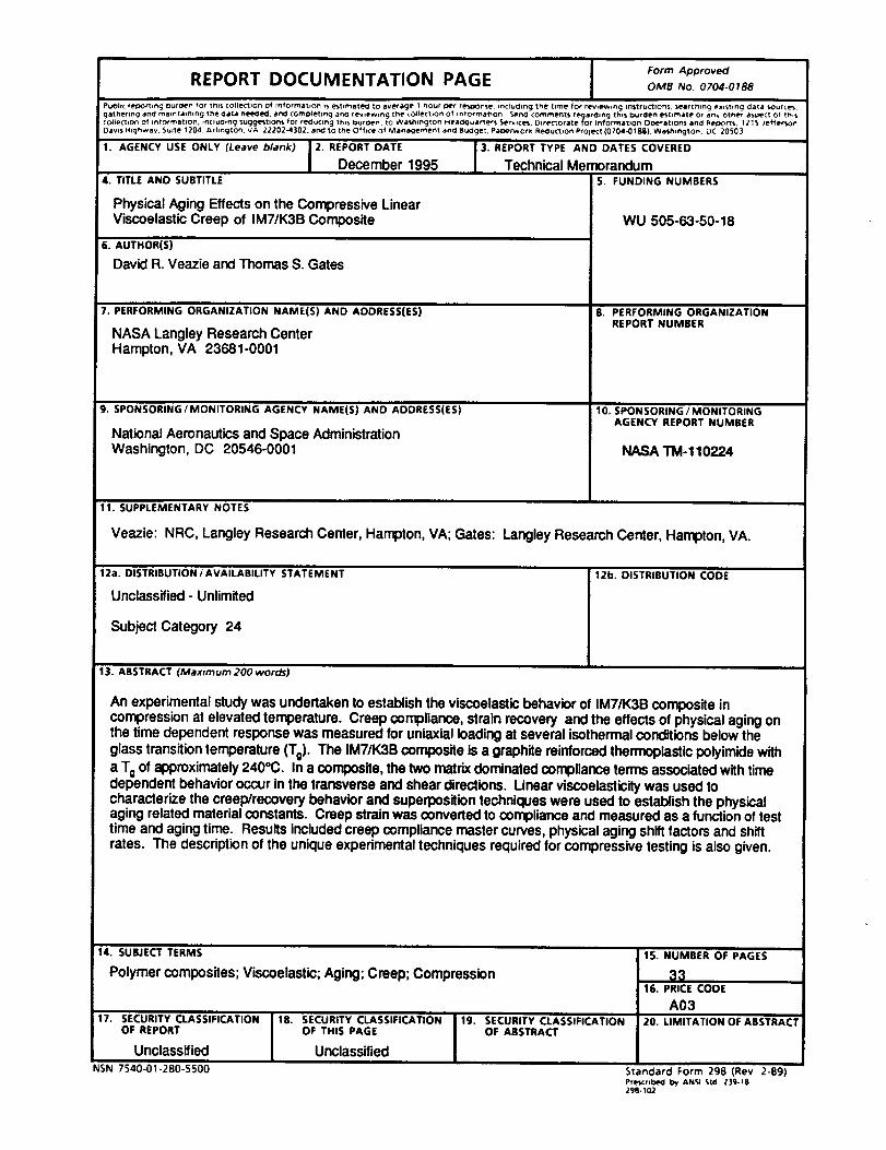
REPORT DOCUMENTATION PAGEForm Approved
OMB No. 0704-0188
PuDhc Cegor_tng ouroen _or tnt$ colleCtiOn of rntormatlon _s estemat_ to average 1 hour Der re_Do_se nctuchng the [iWle for reviewing instructions, searching exlsttng data source%gather*ng anti maJntatntng the Oata ne_*OeO, anti comoletlncj anti rev=ewlng the colleCtion Of Information _ncl comments regarchng this burclen estimate or any Other a,Dec_ O_ thl_
collecIion of information. _ncluchng suggestions for reOucmg this Duroen_ to Washfng_on Heaacluarters Services. Dtre_orate for Inform&tlOn ODeratlOn_ anti AeDO_. 1215 Jefferson
Dav=s H=ghway. Suite 1204, Arhngfon. VA 22202-4]02. and to the Office of Man_emenf and Buaget Paperwork, Reduction PrOleCt (0704-0188), Was_,mgton. DC 20503
1. AGENCY USE ONLY (Leave blank) 2. REPORT DATE
December 19954. TITLE AND SUBTITLE
Physical Aging Effectson the Compressive LinearViscoelasticCreep of IM7/K3B Composite
6. AUTHOR(S)
David R. Veazie and Thomas S. Gates
7. PERFORMINGORGANIZATIONNAME(S)AND ADDRESS(ES)
NASA Langley Research CenterHampton, VA 23681-0001
9. SPONSORING/MONITORING AGENCY NAME(S) AND ADDRESS(ES)
National Aeronauticsand Space AdministrationWashington, DC 20546-0001
:3. REPORTTYPE AND DATESCOVERED
Technical MemorandumS. FUNDING NUMBERS
WU 505-63-50-18
8. PERFORMING ORGANIZATIONREPORT NUMBER
10. SPONSORING / MONITORINGAGENCY REPORT NUMBER
NASA TM-110224
11. SUPPLEMENTARYNOTES
Veazie: NRC, Langley Research Center, Hampton, VA; Gates: Langley Research Center, Hampton, VA.
12a. DISTRIBUTION/AVAILABILITY STATEMENT 12b. DISTRIBUTION CODE
Unclassified- Unlimited
Subject Category 24
13. ABSTRACT (Maximum200 wordS)
An experimental studywas undertaken to establishthe viscoelasticbehavior of IM7/K3B compositeincompression at elevated temperature. Creep compliance, strain recover/ and the effects of physicalaging onthe time dependent response was measured for uniaxial loadingat several isothermalconditions below theglasstransitiontemperature (To). The IM7/K3B composite is a graphite reinforcedthermoplasticpolyimidewitha Toof approximately240°C. In a composite, the two matrixdominated compliance terms associatedwithtimedependent behavior occur inthe transverse and shear directions. Linear viscoelasticitywas used tocharacterize the creep/recovery behavior and superpositiontechniqueswere used to establishthe physicalaging related materialconstants. Creep strain was converted to compliance and measured as a functionof testtime and aging time. Results includedcreep compliancemaster curves, physicalagingshift factorsand shiftrates. The descriptionof the unique experimental techniques requiredfor compressive testing is also given.
14. SUBJECTTERMS
Polymer composites; Viscoelastic; Aging; Creep; Compression
17. SECURITY CLASSIFICATIONOF REPORT
UnclassifiedNSN 7540_1-280-5500
18. SECURITY CLASSIFICATIONOF THIS PAGE
Unclassified
19. SECURITY CLASSIFICATIONOF ABSTRACT
15. NUMBER OF PAGES
3316. PRICE CODE
A0320. LIMITATION OF ABSTRACT
Standard Form 298 (Rev 2-89)Pre_crd_*_l by ANSI StCI Z]lCJ-18298-102

