physical and behavioral circuit modeling of the sp …dtyeh/papers/yeh07_icmc_sp12.pdf · physical...
TRANSCRIPT

PHYSICAL AND BEHAVIORAL CIRCUIT MODELING OF THE SP-12SAMPLER
David T. Yeh, John Nolting, Julius O. SmithCenter for Computer Research in Music and Acoustics (CCRMA)
Stanford University, Stanford, CA
ABSTRACT
Aliasing, usually considered an artifact of discrete timesystems to be avoided, is found to be an aesthetic fea-ture of the E-MU SP-12 sampler/drum machine. This pa-per presents the steps in modeling the SP-12 as a signalprocessing system. Measurements of the characteristicsof the SP-12 are presented. The signal path is analyzedto produce a physically based model of the circuit. Cir-cuit analysis in SPICE provides transfer functions, whichare converted into digital filters by system identification.Aliasing is implemented using interpolation and down-sampling. The results of the algorithm are compared tosamples from the original system.
1. INTRODUCTION
Physical modeling is an approach to deriving efficientalgorithms to simulate various signal processing circuits.Sometimes a physical model is too involved to implementdirectly, but its insights are used to derive a behavioralmodel that approximates the correct response. This issometimes termed virtual analog circuit modeling. Acombination of reverse engineering and circuit analysisallows the systematic formulation of an algorithm thatfaithfully reproduces the character of the original system.In this paper, these techniques are applied to the E-MUSP-12 sampler/drum machine to create an algorithm thatreproduces the sound of this device, which is no longerbeing manufactured.
1.1. Features of the SP-12
The SP-12 (Sampling Percussion), introduced in the mid-80’s, is a sampling drum machine with a sequencer to laydown drum tracks. It features 8 velocity-sensitive pads,8 control slides, and 8-voice polyphony through 8 inde-pendent outputs. It samples at a low 12 bits and 27.5 kHzrate. The Turbo version features 192 kB of sample mem-ory which is about 5 seconds, but each sample can only bea maximum of 2.5 seconds. It features MIDI interfacingand SMPTE synchronization. There are 24 internal drumsamples stored in ROM, and 8 samples that the user canrecord. Each output channel features a different equaliza-tion. The interface allows users to edit samples by loop-ing, truncation, and adjusting the decay.
Figure 1. Control panel of the E-MU SP-12 sampler.
The SP-12 is used for hip hop beats, to give drumsounds a hard edge and grit. A rudimentary pitch shiftercan detune sounds, but also adds a gritty character thatcomes from aliasing. It also features a warm low-passequalization that musicians desire.
1.2. Background material
Literature in virtual analog often discusses alias reduction.Efficient methods of generating bandlimited waveformsfor subtractive synthesis are described in [7, 9].
The canonical virtual analog example is the Moog filter[8, 1]. This work extends upon that earlier work, integrat-ing the analysis of the components into the modeling ofan entire system.
2. OVERVIEW OF THE SP-12 SIGNAL PATH
The SP-12’s signal path consists of an anti-aliasing fil-ter based on operational amplifiers (opamp), a sample andhold at 27.5 kHz, a 12-bit successive approximation quan-tizer, time-domain digital signal processing, a zero-orderhold (see 3.4), and a choice between six optional equal-ization filters to attenuate spectral aliases from the zero-order hold. Two of these filters employ the SSM-2044Voltage Controlled Filter (VCF) chip as a 4-pole lowpasswith time-varying cutoff frequency.
The time-domain processing of the SP-12 featuresvariable-decay time-enveloping of the signal, and a rudi-mentary pitch shifting algorithm common to digital syn-thesis systems of that era [7].

3. DIGITAL IMPLEMENTATION OF THE SP-12
3.1. Assumptions
The following assumptions, while not strictly true, aremade to make the problem more tractable:
• Frequency range of input and output is 0 – 20 kHz.The spectrum outside this range gives insight intothe operation of the device, but is not reproducedby the algorithm.
• Sample rate is 27.5 kHz with no jitter.
• Operational amplifiers are ideal (infinite bandwidthand gain, zero output impedance, no distortion)
• Filters are linear.
• Ideal 12-bit A/D conversion, all quantization stepshave uniform size, yielding a 72-dB noise floor [4].
3.2. Anti-alias filter model
Because the SP-12 involves aliasing effects, one mustensure that the digital implementation aliases properly.Some of the aliasing comes from the non-idealities in theanti-aliasing filters.
The circuits for the analog filters are based upon opampcircuits, for which transfer functions can be found in ana-lytic form. This requires a familiarity with circuit analysisand the formulae are quite involved. An approach moresuited to the toolbox of computer musicians is to find thecomplex frequency response of the circuit by AC analy-sis in SPICE 1 , a simulator that analyzes circuits given adescription of the schematic. Then frequency domain sys-tem identification [3] is used to find the digital filter co-efficients. Practically, this is done with invfreqz.m inMATLAB (Mathworks, Cambridge, MA).
Both the input anti-aliasing and the output equalizationfilters were designed this way. The fitted filters are plot-ted with the transfer function from SPICE in Fig. 2. Anoversampled rate, fs=96 kHz greatly improved the fittingfor the input filters. The output filters fit well using fs =48 kHz.
3.3. Resampling at 27.5 kHz with correct aliasing
To simulate aliasing accurately using a digital implemen-tation, the discrete-time signal is ideally interpolated tothe time-grid corresponding to the sampling rate of theSP-12.
Methods to approximate the ideal interpolation includeusing a variable delay filter [2], or resampling[5] to a mul-tiple of the SP-12’s sampling rate and then downsamplingto the SP-12 rate.
Linear interpolation is found to generate significantspurious artifacts when viewed on a sine sweep. In partic-ular, it has excessive sidelobe levels.
1 http://bwrc.eecs.berkeley.edu/Classes/IcBook/SPICE/
0 5 10 15 20−100
−80
−60
−40
−20
0
Frequency (kHz)
Mag
nitu
de (
dB)
(a) Input filter
0 5 10 15 20−40
−20
0
Frequency (kHz)
Mag
(dB
)
(b) Output filter
Figure 2. Magnitude response of input and output anti-aliasing filters. Shown on linear scale to demonstrate goodhigh frequency match. Input filter is order 11, fs=96 kHz.Output filter is order 5, fs=48 kHz. Fitted filter and SPICEfilter are perfectly overlaid
Time (sec)
Fre
q (k
Hz)
0 0.5 1 1.5 20
5
10
dB
−80
−60
−40
−20
0
Figure 3. Linear sine sweep from 0 to 20 kHz of the re-sampling process shows proper aliasing behavior.
Piecewise spline produces much cleaner results, but re-quires four times oversampling to push unwanted alias-ing at high input frequencies into the noise floor. Thispainstaking process is necessary because the SP-12 is usedas a drum machine and sounds with high frequency con-tent such as cymbal crashes are often sampled.
These methods can be viewed as resampling using aparticular type of interpolation filter[5] and then down-sampling. In general, resampling can be done with bet-ter or longer filters to improve interpolation accuracy for aparticular sampling rate. This is found to be more efficientin practice. In this implementation, the upsampled signalat 96 kHz is resampled to twice the SP-12 frequency anddownsampled by two to generate the correct aliasing. Theresponse of this process to a linear sine sweep is shown inFig. 3.
Time (sec)
Fre
q (k
Hz)
0 0.5 1 1.5 2 2.50
10
20
30
40
dB
−80
−60
−40
−20
0
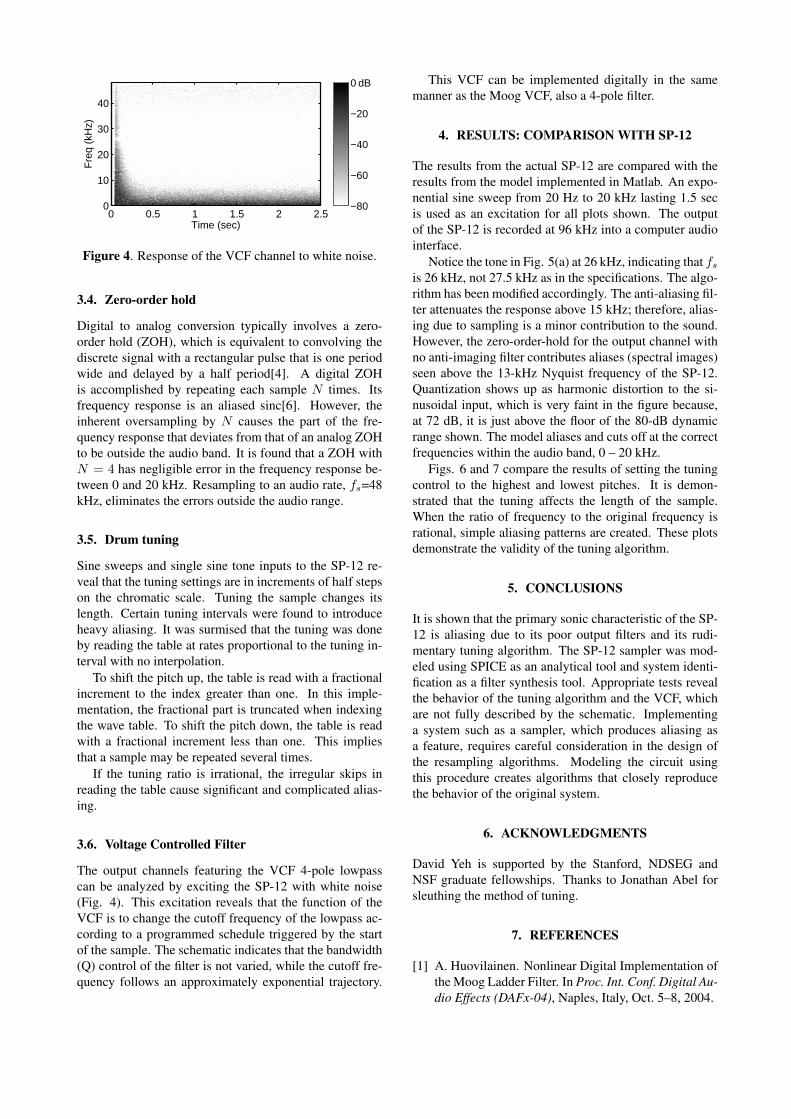
Figure 4. Response of the VCF channel to white noise.
3.4. Zero-order hold
Digital to analog conversion typically involves a zero-order hold (ZOH), which is equivalent to convolving thediscrete signal with a rectangular pulse that is one periodwide and delayed by a half period[4]. A digital ZOHis accomplished by repeating each sample N times. Itsfrequency response is an aliased sinc[6]. However, theinherent oversampling by N causes the part of the fre-quency response that deviates from that of an analog ZOHto be outside the audio band. It is found that a ZOH withN = 4 has negligible error in the frequency response be-tween 0 and 20 kHz. Resampling to an audio rate, fs=48kHz, eliminates the errors outside the audio range.
3.5. Drum tuning
Sine sweeps and single sine tone inputs to the SP-12 re-veal that the tuning settings are in increments of half stepson the chromatic scale. Tuning the sample changes itslength. Certain tuning intervals were found to introduceheavy aliasing. It was surmised that the tuning was doneby reading the table at rates proportional to the tuning in-terval with no interpolation.
To shift the pitch up, the table is read with a fractionalincrement to the index greater than one. In this imple-mentation, the fractional part is truncated when indexingthe wave table. To shift the pitch down, the table is readwith a fractional increment less than one. This impliesthat a sample may be repeated several times.
If the tuning ratio is irrational, the irregular skips inreading the table cause significant and complicated alias-ing.
3.6. Voltage Controlled Filter
The output channels featuring the VCF 4-pole lowpasscan be analyzed by exciting the SP-12 with white noise(Fig. 4). This excitation reveals that the function of theVCF is to change the cutoff frequency of the lowpass ac-cording to a programmed schedule triggered by the startof the sample. The schematic indicates that the bandwidth(Q) control of the filter is not varied, while the cutoff fre-quency follows an approximately exponential trajectory.
This VCF can be implemented digitally in the samemanner as the Moog VCF, also a 4-pole filter.
4. RESULTS: COMPARISON WITH SP-12
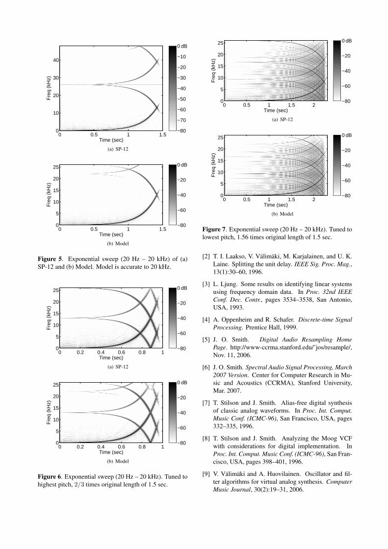
The results from the actual SP-12 are compared with theresults from the model implemented in Matlab. An expo-nential sine sweep from 20 Hz to 20 kHz lasting 1.5 secis used as an excitation for all plots shown. The outputof the SP-12 is recorded at 96 kHz into a computer audiointerface.
Notice the tone in Fig. 5(a) at 26 kHz, indicating that fs
is 26 kHz, not 27.5 kHz as in the specifications. The algo-rithm has been modified accordingly. The anti-aliasing fil-ter attenuates the response above 15 kHz; therefore, alias-ing due to sampling is a minor contribution to the sound.However, the zero-order-hold for the output channel withno anti-imaging filter contributes aliases (spectral images)seen above the 13-kHz Nyquist frequency of the SP-12.Quantization shows up as harmonic distortion to the si-nusoidal input, which is very faint in the figure because,at 72 dB, it is just above the floor of the 80-dB dynamicrange shown. The model aliases and cuts off at the correctfrequencies within the audio band, 0 – 20 kHz.
Figs. 6 and 7 compare the results of setting the tuningcontrol to the highest and lowest pitches. It is demon-strated that the tuning affects the length of the sample.When the ratio of frequency to the original frequency isrational, simple aliasing patterns are created. These plotsdemonstrate the validity of the tuning algorithm.
5. CONCLUSIONS
It is shown that the primary sonic characteristic of the SP-12 is aliasing due to its poor output filters and its rudi-mentary tuning algorithm. The SP-12 sampler was mod-eled using SPICE as an analytical tool and system identi-fication as a filter synthesis tool. Appropriate tests revealthe behavior of the tuning algorithm and the VCF, whichare not fully described by the schematic. Implementinga system such as a sampler, which produces aliasing asa feature, requires careful consideration in the design ofthe resampling algorithms. Modeling the circuit usingthis procedure creates algorithms that closely reproducethe behavior of the original system.
6. ACKNOWLEDGMENTS
David Yeh is supported by the Stanford, NDSEG andNSF graduate fellowships. Thanks to Jonathan Abel forsleuthing the method of tuning.
7. REFERENCES
[1] A. Huovilainen. Nonlinear Digital Implementation ofthe Moog Ladder Filter. In Proc. Int. Conf. Digital Au-dio Effects (DAFx-04), Naples, Italy, Oct. 5–8, 2004.
Time (sec)
Fre
q (k
Hz)
0 0.5 1 1.50
10
20
30
40
dB
−80
−70
−60
−50
−40
−30
−20
−10
0
(a) SP-12
Time (sec)
Fre
q (k
Hz)
0 0.5 1 1.50
5
10
15
20
25 dB
−80
−60
−40
−20
0
(b) Model
Figure 5. Exponential sweep (20 Hz – 20 kHz) of (a)SP-12 and (b) Model. Model is accurate to 20 kHz.
Time (sec)
Fre
q (k
Hz)
0 0.2 0.4 0.6 0.8 10
5
10
15
20
25 dB
−80
−60
−40
−20
0
(a) SP-12
Time (sec)
Fre
q (k
Hz)
0 0.2 0.4 0.6 0.8 10
5
10
15
20
25 dB
−80
−60
−40
−20
0
(b) Model
Figure 6. Exponential sweep (20 Hz – 20 kHz). Tuned tohighest pitch, 2/3 times original length of 1.5 sec.
Time (sec)
Fre
q (k
Hz)
0 0.5 1 1.5 20
5
10
15
20
25 dB
−80
−60
−40
−20
0
(a) SP-12
Time (sec)
Fre
q (k
Hz)
0 0.5 1 1.5 20
5
10
15
20
25 dB
−80
−60
−40
−20
0
(b) Model
Figure 7. Exponential sweep (20 Hz – 20 kHz). Tuned tolowest pitch, 1.56 times original length of 1.5 sec.
[2] T. I. Laakso, V. Valimaki, M. Karjalainen, and U. K.Laine. Splitting the unit delay. IEEE Sig. Proc. Mag.,13(1):30–60, 1996.
[3] L. Ljung. Some results on identifying linear systemsusing frequency domain data. In Proc. 32nd IEEEConf. Dec. Contr., pages 3534–3538, San Antonio,USA, 1993.
[4] A. Oppenheim and R. Schafer. Discrete-time SignalProcessing. Prentice Hall, 1999.
[5] J. O. Smith. Digital Audio Resampling HomePage. http://www-ccrma.stanford.edu/˜jos/resample/,Nov. 11, 2006.
[6] J. O. Smith. Spectral Audio Signal Processing, March2007 Version. Center for Computer Research in Mu-sic and Acoustics (CCRMA), Stanford University,Mar. 2007.
[7] T. Stilson and J. Smith. Alias-free digital synthesisof classic analog waveforms. In Proc. Int. Comput.Music Conf. (ICMC-96), San Francisco, USA, pages332–335, 1996.
[8] T. Stilson and J. Smith. Analyzing the Moog VCFwith considerations for digital implementation. InProc. Int. Comput. Music Conf. (ICMC-96), San Fran-cisco, USA, pages 398–401, 1996.
[9] V. Valimaki and A. Huovilainen. Oscillator and fil-ter algorithms for virtual analog synthesis. ComputerMusic Journal, 30(2):19–31, 2006.