physical aspects of quality assurance in radiation therapy · pdf filephysical aspects of...
TRANSCRIPT

AAPM REPORT No. 13
PHYSICAL ASPECTS OF QUALITYASSURANCE IN RADIATION THERAPY
Published by the American Institute of Physicsfor the American Association of Physicists in Medicine

AAPM REPORT No. 13
PHYSICAL ASPECTS OF QUALITYASSURANCE IN RADIATION THERAPY
AAPM RADIATION THERAPY COMMITTEETASK GROUP 24
with contribution byAAPM RADIATION THERAPY COMMITTEE
TASK GROUP 22
Goran K. Svensson, Chairman, TG-24
Members TG-24
Norman A. BailyRobert LoevingerRobert J. MortonRobert F. MoyerJames A. PurdyRobert J. ShalekPeter Wootton
Kenneth A. Wright
Members TG-22
William F. HansonLowell L. Anderson
C. Clifton LingRobert Loevinger
Kenneth A. Strubler
Consultants
Arnold FeldmanDouglas JonesC. J. Karzmark
Edwin C. McCulloughN. Suntharalingam
May 1994
Published for theAmerican Association of Physicists in Medicine
by the American Institute of Physics

Further copies of this report may be obtained from
Executive SecretaryAmerican Association of Physicists in Medicine
335 E. 45 StreetNew York, NY 10017
Library of Congress Catalog Card Number: 84-4543 1International Standard Book Number: O-883 18-457-5
International Standard Serial Number: 0271-7344
Copyright © 1984 by the American Associationof Physicists in Medicine
All rights reserved. No part of this publication may bereproduced, stored in a retrieval system, or transmittedin any form or by any means (electronic, mechanical,photocopying, recording, or otherwise) without the
prior written permission of the publisher.
Published by the American Institute of Physics, Inc.335 East 45 Street, New York, NY 10017
Printed in the United States of America
TABLE OF CONTENTS
CHAPTER 1Introduction . . . * . . . . * . . . . * . . . . . . . . . . . . . . . . . . . . . . . . . * . . . .
CHAPTER 2
Dosimetric Accuracy and Equipment Tolerances . . . . . . . . . . . . 7
Figure 1 . . . . . . . . . . . . . . . . . . . . . . . . . . . . . . . . . . . . . . . . . . . 9Figure 2 . . . . . . . . . . . . . . . . . . . . . . . . . . . . . . . . . . . . . . . . . . . 11Figure 3 . . . . . . . . . . . . . . . . . . . . . . . . . . . . . . . . . . . . . . . . . . . 12Figure 4 . . . . . . . . . . . . . . . . . . . . . . . . . . . . . . . . . . . . . . . . . . . 13
CHAPTER 3
Measurement Equipment Used in Radiotherapy
Introduction . . . . . . . . . . . . . . . . . . . . . . . . . . . . . . . . . . . . . . .Recommendations and Literature Review. . . . . . . . . . . . . .Summary . . . . . . . . . . . . . . . . . . . . . . . . . . . . . . . . . . . . . . . . . . . .T a b l e I . . . . . . . . . . . . . . . . . . . . . . . . . . . . . . . . . . . . . . . . . . . .
CHAPTER 4
Simulation and External Beam Treatment Equipment
Introduction . . . . . . . . . . . . . . . . . . . . . . . . . . . . . . . . . . . . . . . 23Dosimetry . . . . . . . . . . . . . . . . . . . . . . . . . . . . . . . . . . . . . . . . . . 23Geometry . . . . . . . . . . . . . . . . . . . . . . . . . . . . . . . . . . . . . . . . . . . 25Electron beam equipment . . . . . . . . . . . . . . . . . . . . . . . . . . . . 26Co-60 teletherapy equipment . . . . . . . . . . . . . . . . . . . . . . . . 27Treatment accessories . . . . . . . . . . . . . . . . . . . . . . . . . . . . . . 27Simulators . . . . . . . . . . . . . . . . . . . . . . . . . . . . . . . . . . . . . . . . . 27Emergency Off . . . . . . . . . . . . . . . . . . . . . . . . . . . . . . . . . . . . . . 27Table II . . . . . . . . . . . . . . . . . . . . . . . . . . . . . . . . . . . . . . . . . . . 29
5
14152021
-3-
CHAPTER 5
Treatment Planning
Introduction . . . . . . . . . . . . . . . . . . . . . . . . . . . . . . . . . . . . . . . 30Table III . . . . . . . . . . . . . . . . . . . . . . . . . . . . . . . . . . . . . . . . . . 31Table IV . . . . . . . . . . . . . . . . . . . . . . . . . . . . . . . . . . . . . . . . . . . 33Table V . . . . . . . . . . . . . . . . . . . . . . . . . . . . . . . . . . . . . . . . . . . . 3 6Table VI . . . . . . . . . . . . . . . . . . . . . . . . . . . . . . . . . . . . . . . . . . . 3 7
CHAPTER 6
Brachytherapy
Introduction . . . . . . . . . . . . . . . . . . . . . . . . . . . . . . . . . . . . . . .Sealed sources . . . . . . . . . . . . . . . . . . . . . . . . . . . . . . . . . . . . .Treatment planning and dose evaluation . . . . . . . . . . . . .Remote controlled, high intensity irradiators . . . . . .
CHAPTER 7
Radiation Safety
Introduction . . . . . . . . . . . . . . . . . . . . . . . . . . . . . . . . . . . . . . . Personnel dosimetry . . . . . . . . . . . . . . . . . . . . . . . . . . . . . . . .Radiation survey . . . . . . . . . . . . . . . . . . . . . . . . . . . . . . . . . . .Brachytherapy . . . . . . . . . . . . . . . . . . . . . . . . . . . . . . . . . . . . . .Conclusion . . . . . . . . . . . . . . . . . . . . . . . . . . . . . . . . . . . . . . . . .
APPENDIX A
Quantities & Units in Teletherapy & Brachytherapy..
Table VII . . . . . . . . . . . . . . . . . . . . . . . . . . . . . . . . . . . . . . . .APPENDIX B
Bibliography . . . . . . . . . . . . . . . . . . . . . . . . . . . . . . . . . . . . . . . . . . . .
38
434 6
: :48505 1
52
53
5 4
- 4 -

CHAPTER 1
INTRODUCTION
Quality assurance in radiation therapy includes those procedures that ensure aconsistent and safe fulfillment of the dose prescription to the target volume, withminimal dose to norma1 tissues and minimal exposure to personnel.
A comprehensive quality assurance program is necessary because of the import-ance of accuracy in dose delivery in radiation therapy. The dare-response curve inradiation therapy is quite steep in certain cases, and there is evidence that a7-10% change in the dose to the target volume may result in a significant change intuner control probability [53]. Similarly, such a dose change may also result ina sharp change in the incidence and severity of radiation induced morbidity.
Surveying the evidence on effective and excessive dose levels, Herring andCompton [38] concluded that the therapeutic system should be capable of deliveringa dose to the tumor volume within 5% of the dose prescribed. Report 24 from theInternational Commission on Radiation Units and Measurements [53] lists severalstudier in support of this conclusion.
Surveys have indicated that errors occur with some finite frequency even ininstitutions which are regularly reviewed by physicists from the RadiologicalPhysics Center [31] and the Centers for Radiological Physics [117]. Anationwide survey of Co-60 teletherapy units was conducted by the National Centerfor Devices and Radiological Health (NCDRH), which was fomerly the bureau ofRadiological Earth and the National Bureau of Standards [128}. The surveyincluded 75% of the Co-60 units (751) in use and showed that doses delivered by 17%of these units differed from the requested doses by at least 5% and that 4% of thedelivered doses differed by 10% or more.
Sources of error in radiation therapy include tumor localization, lack ofpatient immobilization, field placement, human errors in calibration, calculation,daily patient setup, and equipment-related problems. Many of these equipment andcalculational errors can be minimized through a program of periodic checks.
The discussion and accompanying flow chart of a systems approach to radiationtherapy given in ICRU Report No.24 [53] and in the CR0S Blue Book [106] pointsout that the planning and delivery of a course of radiation therapy is a continuousprocess with any feedback loops. Looking at treatment in this manner allows one torealize that the assurance of quality at each step in necessary to permit credibleassessment of results of treatment.
Even though a comprehensive quality assurance (QA) program in radiation therapyhas both clinical and physical components, this document will address only physicaltests and procedures necessary to ensure that a radiation therapy facility canaccurately and reproducibly deliver the prescribed dose to the target volume withminimal dose to normal tissue. This document also addresses the problems of optimaldesign and operation of a facility with regard to radiation, mechanical, andelectrical safety.
A QA program, should be established for each radiation therapy facility.However, the nature of the program may depend on the objectives and resources of theclinical services and facili t ies.
- 5 -

The medical radiological physicist is often called upon to exercise her/hisjudgment as to the magnitude of an adequate quality assurance program which isconsistent with the goals of the radiation oncologist . I t is , therefore, a majorpurpose of this report to provide guidance to the physicist called upon to designand implement a quality assurance program for radiation therapy. Furthermore, thisdocument provides information to regulatory agencies, professional organizations,and hospital administrations in their consideration of the resourcer needed for highquality radiation treatment delivery.
The document has been divided into six major areas; Accuracy and tolerances. Measurements, Simulation and ex-ternal beam treatment equipment, External beam treatment planning, Brachytherapy and Radiation safety.
We are indebted to the Center for Devices and Radiological Health, Rockville Maryland, for sponsoring a two dayworkshop on this document on 11- 12 March 1982.
- 6 -

CHAPTER 2
DOSIMETRIC ACCURACY AND EQUIPMENT TOLERANCES
A quality assurance document needs to contain clinically relevant recommenda-tions about acceptable uncertainties in dosimetric procedures sad in mechanicalalignment of treatment equipment. A large number of parameters, all having someinaccuracy, contribute to the overall uncertainty in the three-dimensional dose .distribution delivered to a patient.
It is our experience that most QA documents specify acceptable tolerance levelsfor individual parameters without considering the cumulative effect on the uncer-tainty in the dose delivered to a specified volume in a patient. The reason is thatsuch an uncertainty propagation is very difficult and considered by many to bescientifically unsound because we are dealing with the combined effect of systematic(non-random) and random uncertainties [68]. On the other hand. detailed recom-mendations about individual equipment parameters and dosimetric procedures do notguarantee technical quality unless the cumulative effect at the patient level isaddressed. Analysis of individual parameters should not be the main focus of a QAprogram but rather serious attempt should be made to understand the cumulativeeffect of all procedures at the patient level. One would begin by defining anacceptable overall uncertainty, resulting from all radiotherapy procedures. Thisuncertainty is the result of many procedures that have both random and non-randomuncertainties associated with then. The problem is to define these various uncer-tainties sad combine then in a meaningful way.
The problem of characterising the result of a set of measurements by an overalluncertainty, combining random and non-random uncertainties, has received consider-able attention in the recent scientific literature [68,91]. Recognizing the needfor a consensus method of making that combination, an international working party,made up of representatives of the national standards laborstories of 12 countries,has fomulated such a recommendation [58]. While not universally agreed upon, andnot free of subjective suspects, the recommended method represents a reasonable andself-consistent approach. It is recommended that random uncertainties be determinedas usual by statistical methods. and be represented by standard deviations. Allother uncertainties are to be estimated in some manner, generally as a simple“guesstimate”‘, so as to correspond roughly to one standard deviation by assumingthat the distribution of uncertainties follows a normal distribution. These non-random uncertainties are to be combined in quadrature with the random uncertaintiesto obtain a combined uncertainty, characterized by a number that can be consideredto be roughly like a standard deviation. Finally the combined uncertainty can bemultiplied by some factor, say 2 or 3, to get an overall uncertainty, which can belooked upon as very l approximately a 95% or 99% confidence interval, respectively.
A somewhat similar method of uncertainty analysis was used by Loevinger andLoftus [76] in deriving a model for dosimetric accuracy in calibration procedures.The results of their analysis has provided valuable guidance as to the achievabledosimetric accuracy in radiation therapy [53].
In dealing with individual machine parameters, the suggested method of quad-ratic summation makes it possible to set specifications which are reasonable andconform with acceptable overall uncertainties.
- 7 -

Figure 1 shows how uncertainties of the various components described in thisdocument may interact. One important specification in a QA program should be theprecision uncertainty in delivering a dose to any point in a patient. I t isgenerally agreed that ±5% (here assumed to represent 2 standard deviations) isclinically acceptable and technically achievable [53]. Figure 1a providesacceptable level6 of uncertainties of the various component.6 in the treatmentprocedure. The cumlative effect of there uncertainties is within the limits of theoverall uncertainties provided that quadratic summation is an acceptable method ofpropagation.
The spatial uncertainty in aiming one or several beams at a target within apatient depends on the mechanical accuracy of the treatment machine and the effectof breathing and patient motion on organ displacement. While the effect of organmotion on the geometric precision can only be approximately evaluated at this time,mechanical accuracy is rather well documented. Estimates of the contributions tothe geometric precision from both classes of uncertainties are exemplified in Figure1b. The problem then becomes, what is the overall impact of all sources of spatialuncertainty on the expectation of delivering a specified dose to the target volumeand to critical organs in a specific patient? It is no comfort to a patient that onthe average the dose to the spinal cord in a given facility does not exceed cordtolerance if in that patient's case tolerance is exceeded.
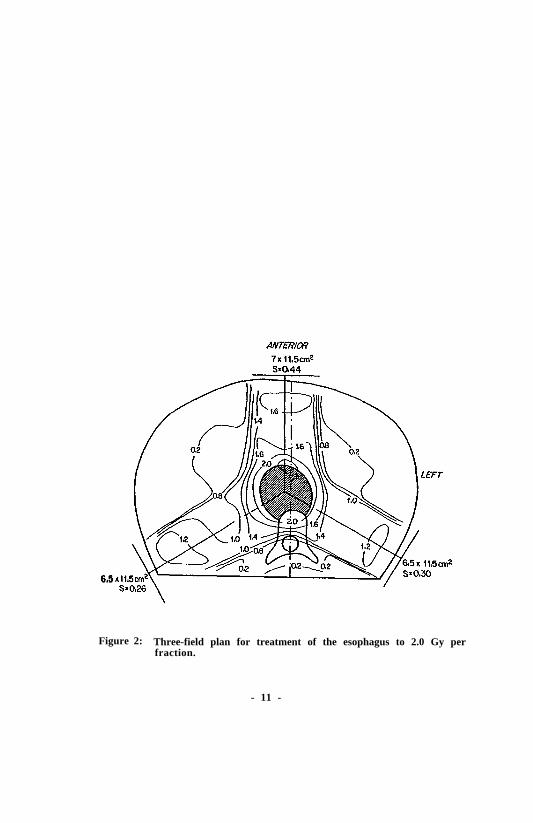
Given that the uncertainties in treatment delivery outlined above are inevi-table, several things follow: 1) The overall impact of all sources of uncertaintymust be evaluated, rather than concentrating on individual components; 2) Whengeometric uncertainties predominate, their impact will be felt quite differently indifferent regions of the patient (i.e. regions near the field edge may be much moresensitive to positional uncertainties than regions in the field center; 3 ) I t i stherefore necessary to evaluate the anatomic impact of treatment uncertainties; and4) The uncertainties in dose may be non-linearly related to the geometric uncer-tainties and may be asymetric. These points are now illustrated by an example:Consider a three-field treatment (anterior; right and left posterior obliquestangential to the spinal process) of an esophageal tumor using 8 MV x-ray beams(Figure 2).
If one conriders the geometric uncertainty due to mechanical effects and in-accuracy of patient position and organ motion as shown in Figure lb, the uncertaintyin dose per fraction is illustrated by the solid line in Figure 3. The Z axis isthe patient midline in the anterior to posterior direction (Figure 2). Thedosimetric uncertainties art i l lustrated by the dashed line in Figure 3. Theuncertainties in these examples represent 2 standard deviations. The combineduncertainty per dose fraction in the dose profile along the Z axis is shown inFigure 4.
From this example it can be seen that the analysis in Figure 1a may be applic-able to the central portion of the treatment volume but not to organs outside themain beam where the relationship between uncertainty in dose and position are notl inear. For this reason it has been suggested that, where this lack of linearityexists, three calculations should be made for each cart. one with the nominalspatial relationships and one for each extreme displacement, perhaps of 1.5 standard
deviations.
It is important to recognize that treating the problem of quality assurance inthis manner allows some flexibility as to the tolerance values of the individualcomponents in the system. For example, if J department, due to policy or limitedresources, has eliminated one component (e.g. isocentric treatments) the additional
- 8 -
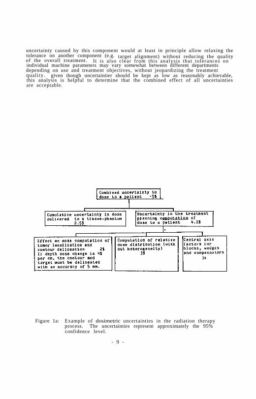
uncertainty caused by this component would at least in principle allow relaxing thetolerance on another component (e.g.of the overall treatment.
target alignment) without reducing the qualityIt is also clear from this analysis that tolerances on
individual machine parameters may vary somewhat between different departmentsdepending on use and treatment objectives, without jeopardizing the treatmentquali ty. given though uncertaintier should be kept as low as reasonably achievable,this analysis is helpful to determine that the combined effect of all uncertaintiesare acceptable.
Figure 1a: Example of dosimetric uncertainties in the radiation therapyprocess. The uncertainties represent approximately the 95%confidence level.
- 9 -

Figure lb: Example of spatial uncertainties (at the 95% confidence level) inthe radiation therapy process.
- 10 -
6.5
Figure 2: Three-field plan for treatment of the esophagus to 2.0 Gy perfraction.
- 11 -

Figure 3: The dose uncertainly in the three-field plan shown in figure 2. The profile is taken in the APdirection along the midline. The dashed line shows the uncertainty in the dosimetry and thesolid line is the uncertainly due to set-up errors, organ motion and breathing. These errors areidentified in figure lb.
- 12 -

Figure 4: The solid line shows the Profile of the dose per fraction from thetreatment plan in Figure 2. The profile is taken in the AP directionalong the midline.expressed as ±2 σ.
The dashed lines show the dose uncertaintyFigures 1-4 are reprinted with permission from
Int J. Rad. Onc. Biol. Phys. Supplement 1. Svensson, GK: QualityAssurance in Radiation Therapy (1983) Pergammon Press, Ltd.
- 13 -

CHAPTER 3
MEASUREMENT EQUIPMENT USED IN RADIATION THERAPY*
INTRODUCTION
The evaluation of accuracy and precision of determination of absorbed dose isa very important component of any physical quality assurance program. Commonlyemployed dosimeters do not measure dose or exposure directly and the accuracy of lgiven dosimetric system is subject to change without obvious indication. Accessoryequipment (e.g., isodose plotters) also can contribute significant errors, thereforethis equipment should receive equal scrutiny.
There are many steps in the process of estimating dose in a patient. Bach stepmay introduce errors; therefore careful control of all factors is justified. Vari-ation in biologica1 response between patients and uncertainties of optimal thera-peutic dose do not justify dosimetric expediency, due to potential compounding oferror*. Uncertaintier in theoretical conversion constant are on the order of 3%[50]. The incorporation of refinements in these factors (or reduction of othertypes of systematic errors) in patient dosimetry requires consideration of theclinical experience obtained with less accurate data. The effect on the deliveredtarget dose or dose distribution must be clearly understood before changes areimplemented.
It is possible that a significant error can escape detection under the best ofcircumstances. For this reason, it is highly recommended that all facilitiessubscribe to some form of outride check of their dose delivery capability. Dosimet-ric comparisons between institutions are useful for this purpose. Some examples ofsuch services follow. The AAPM Radiological Physics Center provides on-site visitsand mailed thermoluminescent dosimeter (TLD) comparisons for institutions engaged incertain treatment protocols [36]. The National Bureau of Standards conductsmailed Fricke dosimeter comparisons for high-energy electrons [26]. TheMPH-coordinated Centers for radiological Physics (CRP) offer on-site dosimetrychecks and wiled TLD evaluation to certain facilities (funded by NCI). There aresome private concerns and universities that offer mailed TLD measurement service aswell. Site visits by an outride group are more comprehensive and preferred, butmailed TLD checks are recommended as the minimum necessary l m part of a QA program.
The following are basic characteristics that should be evaluated for all newlyintroduced dosimetric instrumentation and periodically verified during use byrecalibration or constancy checks (when appropriate). Some of these characteristicsapply to ionization chambers only.
*Detailed considerations are limited to photon and electron therapy.
- 14 -
1.
2.
3 .
4 .
Accuracy and constancya. Energy dependenceb. Dose rate dependenceC. Angular dependenced. Collecting voltage polarity dependence and equilibration tinee. Dose history dependencef. Size and shape limitations relative to dose gradients for anticipated useg. Air cavity venting
Reproducibility
Nonlinearity of response
Spurious signalsa. Charge leakageb. Extra-cameral radiation signals (cable, connector, chamber stem,
pre-amplifier effects)C . Cable stressd. Electromagnetic interferencee. Assorted artifacts for light emission and transmission dosimeters
The user of each instrument should be capable of analyzing all of the above_.potential sources of error (or of judging when they need not be evaluated).
Appropriate quality assurance tests depend on equipment type. For the purposeof this report, equipment will be assigned to the following categories.
1. Radiation measurement equipmenta. The local standard instrumentb. Relative dosimetric equipment (TLD, film, diodes, ion chambers, et al.,
including devices for evaluating beam constancy)C. Multipurpose electrometers and separate readout devicesd. Survey instruments
2. Dosimeter positioning and recording equipment (scanners and plotters)
3 . Phantoms
4. Accessory equipment (thermometer, barometer, ruler, et al.)
RECOMMENDATIONS AND LITERATURE REVIEW
1. Radiation measurement equipment
a. The local standard instrument
Field instruments are portable instruments that arc used for calibration andother measurements on radiation therapy machines [103]. A field instrument issaid to have a calibration directly traceable to NBS w h e n t h e i n s t r u m e n t h a s b e e ncalibrated either at NBS or at an AAPH-Accredited Dosimetry Calibration Laboratory(ADCL) against a secondary standard that has itself been calibrated at NBS [103].
*Radionuclide calibration equipment will be discussed in Chapter 6
- 15 -

One field instrument, having a calibration directly traceable to NBS, should beconsidered the local standard. As such it should be reserved for calibration ofradiation therapy beams, for intercomparison with other instruments that have cali-bration directly traceable to NBS, and for calibration of other field instrumentsthat are used for measurements other than therapy beam calibration.
The local standard instrument should be maintained with care by a qualifiedmedical radiation physicist [2]. Redundancy in calibrated instrumentation (andsources) is required [5,41]. The optimal frequency of calibration iscontroversial at the time of writing [4,63,103,113]; however, a period of 2 yearswas suggested in the AAPH code of practice for x-ray linear accelerators [2] andis a requirement of the Nuclear Regulatory Commission for Co-60 teletherapy units[131]. A minimum period of four years with interim intercomparison is beingrecommended by the AAPH at the time of preparation of this report [4]. If the in-etrument is shipped to and from the calibration laboratory, special attention mustbe paid to satisfactory packing to guard against mechanical shock and damage. It issuggested that linearity and extra-camera1 radiation signal teats be conducted justprior to the time of each instrument calibration, Radionuclide constancy checks[2,81] should be done before and after each chamber calibration, and just prior tothe time of and immediately after each machine calibration. This applies especiallyif a significant difference in indicated dose or dose rate is noted. Simpleelectronic constancy tests should be conducted prior to each use [44,79,103].Tests should include (where appropriate) charge leakage, chamber bias, electrometerpotential confirmation (if battery powered), and electronic constancy check. Thiscan be accomplished by condenser chamber "discharge check" or the use of aconstant-current source. Explicit records should be kept of all constancy tests.The initial calibration should include as many radiation qualities as possible inthe anticipated region of use. Careful consideration should be given to anydeviation from chamber calibration conditions during machine calibrations (notablydose rate. field size, and energy, e.g. , HVT and homogeneity coefficient).
Numerous small sources of error exist during instrument calibration intercom-parisons resulting in an uncertainty, under “optimal” conditions, of approximately1% [53]. Individuals performing calibration comparisons should be error-consciousand maintain a detailed history for each instrument. The local standard should bereturned to the RCL if sensitivity changes of more then 2% are detected.
Field instruments, used for measurements other than therapy beam calibration.i.e., on-patient dose measurementsbe calibrated by comparison with the local standard instrument. The constancy of
, where therapy patient dose may be adjusted, may
them field instruments can be maintained with the same constancy check methods usedfor the local standard.
b. Relative dosimetric equipment
Readouts labelled “dose” can be especially misleading to the user. Accuracy.precision, linearity, and the presence of spurious signals should be checkedfrequently. Energy dependence is very great in some systems, e.g., radiographicfilm and diodes [15]. Diodes also are subject to changing sensitivity with use.Systems used for in vivo patient dosimetry and those noted for their variable, non-linear response (e.g. , film), should be calibrated frequently under similarscattering conditions (ideally, during each use).
When relative dosimetric equipment is employed to obtain relative treatmentfactors (field factors, dose vs. depth, etc.), the user should be aware that theredata are as important as the primary calibration, sod all the errors listed in the
- 16 -

Introduction are possible. For example, no system can be assumed to have a linearresponse, and. in addition, the spurious signal level may very during or betweenmeasurement. When potential errors of this type exist, systems used for phantomstudies to establish treatment factors should be spot-checked with a second system(e.g., TLD) at each radiation quality.
Thermoluminescent dosimeters (TLD) and similar small detectors typically haverelatively large variability between dosimeter elements. This require6 the user tobe knowledgeable in statistical sampling and analysis techniques in order to obtainresults with the necessary accuracy.
Teletherapy beam constancy evaluation devices are very useful for rapid checksof several parameters (see Chapter 4); however, adjustment of machine parametersshould not be based solely on measurements obtained with such instruments. Periodicevaluation using l Cobalt-60 teletherapy unit can be employed to check constancydevices which are used for x-ray and accelerator therapy machines. However. it iswell documented that even radionuclide teletherapy units are not infallible [69].
C. Multipurpose electrometers and separate readout devices
Electrometers, digit .1 voltmeters, etc. , have been singled out due to thesignificant increase in their use and as a reminder that these instruments are anintegral part of a dosimetric system. Due to their complexity, the average userprobably does not understand the full theory of operation. Semiconductor componentscan provide long periods of dependable service but are subject to damage by voltagetransients. Each sensitivity range should be evaluated separately; autoranging isnot recommended unless each range is checked periodically, due to possibledifferences in electronic sensitivity and/or shifts of the zero position. Thecollection potential for ionization chamber mad the electrometer battery pack (ifpresent) should be checked at least once during each measurement sequence.Constant-current end standard capacitance calibration or constracy check proceduresare useful to differentiate between chamber and electrometer me the source ofchanges in sensitivity or precision [66,79]. Any separate readout device must beincluded in the system calibration and constancy checks.
d. Survey instruments
The typical survey instrument is prone to meet source, of errors listed at thebeginning of this chapter, notably energy dependence, angular dependence, and non-linearity [101]. A greater overall uncertainty is considered acceptable (+30%)for measurement near the maximum permissible dose rates [51]; however, regulatoryagencies may require more demanding accuracy limits [133]. Tests for singular andenergy dependence are relatively difficult to perform in a typical hospitalenvironment, Survey meters purchased for the purpose of estimating exposure or doseshould be obtained only from manufacturers who supply appropriate detailed dataobtained with acceptable techniques [7]. Wherever possible. these data should bespot-checked. e.g., side vs. front exposure. Relatively low energy sensitivity canbe spot-checked in the hospital setting (with some difficulty) by using calibratedhigh-activity radionuclide sources (corrected for self absorption), or by exposureOf calibrated field instruments to scattered radiation from a superficial therapyunit . The generally accepted routine calibration procedure involve6 recordingreading at varying distance from calibrated Cs-137, Co-60, or Ra-226 sources withdue consideration to the dimensions of the sensitive volume. In a typica1 room,scattered radiation is significant when using an uncollimated source, and lack ofcorrection will result in underestimates of exposure rates during an actual survey(>25% error is possible). The scatter contribution can be estimated with sufficient
- 17 -
accuracy during calibration by making additional measurements with a lead shield(approximately 7 HVT’s) placed midway between the source and the instrument. Thelead brick holder should be left in place for all readings. The overall correctionis determined by the ratio of calculated free-air exposure rate to instrumentreading without lead minus the reading with lead. The scatter correction varieswith distance, nuclide, and instrument type due to differences in scatteredradiation energy and changes in scatter geometry. Collimated sources must becalibrated in terms of exposure due to scatter from their containers.
End caps or windows should be in place when the secondary electron rangeexceeds the inherent wall thickness. Although somewhat complex and arbitrary,additiona1 (approximately air-equivalent) buildup cap material should be used if thecap supplied does not approach the electron range during calibration or survey(typically above approximately 1 MeV). Wall thickness for calibration should matchthe nuclide used, not the energy to be surveyed, and vice versa.
2For example, total
wall thickness (cap plus inherent) of approximately 0.4 g/cm should be used forinstr umentg/cm2
calibrations with Co-60 or Ra-226, whereas a cap of approximately 2.5would be required to assure near charged-particle
2equilibrium for surveys of
a 10-MeV photon unit, and omission of cap (<10 mg/cm inherent wall) would bemost appropriate for measurements of photon sources less than 100 keV to minimizew a l l a t t e n t i o n . The surveyor should be aware that readings obtained with ahand-held instrument accurately calibratcd in air with Cs-137, may deviate fromactual dose by approximately -30% to +10% due to tissue absorption and scatteringdifferences from free air.
Instruments should be calibrated at least annually at two or more positions oneach sensitivity level (one position near maximum reading and one position below 1/2maximum). built-in radionuclide check sources are highly desirable; check-sourcereadings should be obtained prior to each measurement sequence.
Care should be exercised regarding ion collection or counting efficiency as afunction of instantaneous dose rate , e.g., the peak instantaneous dose ratetypically is approximately 1000 times greater than the average rate for pulsedhigh-energy linear accelerator x-ray units.
RF interference sometimes is experienced and shielding of the instrument or RFsource may be necessary.
2. Dosimeter positioning equipment
The following relationships should be evaluated prior to and after each meas-urement sequence; the spatial accuracy goal should be ±1 mm (actual vs. indicatedposition in three dimensions).
a. Coincidence of the center of the sensitive detector volume with positionscales on the scanning device both at the center and extremes of the regionto be evaluated.
b. Coincidence of the scanner scale position with the plotter andremote-control-indicated position at both the center and the extremes (orconfiguration of position recorded by digital systems).
C. Mechnical hysteresis (coincidences of plotter and summer position when agiven position is approached from different directions). Certaincommercial models have been very poor in this regard.
- 18 -
The following additional problem areas will generally need to be addressed by aphysicist due to their complexity.
a. Change in detector position with respect to scanner- or computer-indicatedposition (static or dynamic).
b. Spurious signals due to irradiation of different portions of cables,connectors, or signal amplifiers [50].
.c. Nonlinearity of percentage stepping circuits (e.g., automatic isodosep lo t t e r s ) . There are several sources of nonlinearity.
d. Response-time interactions between detector signal. servo mechanisms, andbeam intensity transients [50].
e. Variations in pressure around air-chamber volumes in a water phantom.
f. Variation in apparent sensitivity of film densitometer scanners due tochanges in distance between film and light sensor (a mechanical problem ofscanning system).
g. All applicable potential errors previously discussed in Item 1 (Radiationmeasurement equipment).
3 . Phantoms
Whenever possible, relative dose measurements should be made in water phantomwith the beam entering through the open top or through thin side windows. Water isnot exactly soft-tissue equivalent but is considered the best readily availablesubstance for phantom material at all energies. Basic considerations for solidphantom design and use have been discussed by others [135]. The following testsshould be carried out for quality assurance purposes.
a. Individualism solid phantom sheets. Measure and record mass thickness andlinear thickness. Calculate density and compare it to the standard valuefor the substance used.
b. Check stacked mass thickness of layered solid phantoms vs. summedindividual mass thicknesses (improve flatness if indicated and practical).Compression mechanisms are useful and often essentia1, e.g., forparallel-to-beam film dosimetry.
c. Check actual depth of fixed detector holders below surface, as well asaccuracy of hole diameter and depth(s) for detector insertion to confirmthat only minimal air spaces exist.
d. If the beam enters through a solid side of a water phantom, measure degreeof bulge or sag prior to each use (0.5% to >1% dose errors are possiblebefore this is noticeable by eye).
e. Determine the temperature of the phantom material during each use or allowsufficient time for it to come to equilibrium with the air temperature.
- 19 -

f. Confirm that phantom dimensions are adequate in all directions for intendeduse. A classic error results if additional phantom material is not addedoutside of water tanks when data are collected near one or more of therider of a t a n k .
g. Apply appropriate correction factors to data collected in solid phantoms.
4. Accessory Equipment
Each individual who performs calibrations of radiation therapy equipment shouldhave access to a thermometer, barometer, and linear rule of appropriate accuracy.Mercury barometers are conridered inherently accurate if they have been checked witha long, accurate rule and if gravity and temperature corrections are applied(typically -3 mmHg). Aneroid barometers should be compared to a mercury barometerat least once per year (ideally near the time of each use). The reader is remindedthat most common barometric reports and instruments relate to a specific elevation.Serious errors could result if these instruments or reports were used without propercorrection when there is a significant difference from the reference elevation.Aneroid barometers may lose their calibration when exposed to extremes of pressure,such as during air travel in an unpressurized compartment [2]. Errors of theorder of 1 degree Celsius are common, and , if combined with 1 mmHG (133 Pa), and1 mm distance error, could introduce errors in the order of 0.5% to 1%. It shouldbe noted that graph paper scales may have errors approaching 1% and that copymachines may significantly distort graphic materials.
Substances employed for photon attenuation analysis (HVT) should be ofestablished purity. These also should be individualized (each piece checked andlabelled) and linear thicknesses determined by measurements of mass thickness.
No measurement device can be trusted to maintain its calibration over anyextended interval of time or to possess the calibrated degree of accuracy in uncali-bated regions. Arbitrary but practical limits of calibration and check frequencieshave been established based on pert experience and logic. Table I lists recommendedminimal tests, specific frequencies, and accuracy goals for the confirmation ofmeasurement equipment used in clinical radiation therapy. Any indication ofmalfunction should be followed by detailed evaluation, e.g., as for new equipment.
- 20 -

TABLE I
PARTIAL LISTING OF MINIMAL QUALITY ASSURANCE TESTSAND LIMITS FOR MEASUREMENT EQUIPMENT
- 21 -

- 22 -

CHAPTER 4
EXTERNAL BEAM TREATMENT AND STIMULATION EQUIPMENT
INTRODUCTION
The ability to deliver the correct target dose to a patient depends on severalfactors, the most significant of which are an exact dose calibration, accuratelydetermined depth dose and off-axis dose characteristics, and knowledge of theprecise patient geometry used during irradiation. Although these requirements aregenerally common to all types of treatment equipment (sources), a detaileddescription of the influencer of the various factors entails categorizing equipmentaccording to design end use. For example, using a modern isocentric treatmentmachine requires understanding of the exact geometry in which the patient istreated. Only when the size and direction of the beam and the source-to-axisdistance are known with precision can an accurate calculation of the relative dosedistribution end/or total dose be performed. The validity of such a calculat ion isdependent on the mechanical precision of the movements of the machine itself and ofpropertier of the treatment accessories such as wedges and blocks, etc. As aresult, a quality assurance program must include tests of dosimetric characteristicsas well as of mechanical and geometric integrity.
Table II lists the types of equipment and the different parameter for whichquality assurance testing is recommended.
I. DOSIMETRY
The first item, Dosimetry, is subdivided into a central axis dose calibrat ionand constancy checks. Constancy checks refer to periodic tests of performance ofcertain equipment parameters, in this case the five listed in I.B.1 to I.B.5.
I .A . Central axis dose calibrations should follow established guidelines asoutlined in detail in various publications [1,2,41,50,105].
The instrument of choice for these calibrations should be a local standardionization chamber or field instrument (see section on measurement equipment ford e f i n i t i o n s ) h a v i n g a c a l i b r a t i o n f a c t o r d i r e c t l y traceable to the National Bureauof Standards. For high-energy photon beams, it is recommended [1,2,105] that dueto the influence of secondary electron contamination , calibrations be performed atthe depth of dose maximum or at a defined greater depth. Calibration depthsvs. photon energies are tabulated in [105]. For electron beams, calibrationsshould be performed et the depth of dose maximum [105]. The central axis dosecalibration should be performed in water or a suitable solid phantom [52,105].The technique for converting ion chamber readings to absorbed done in water orplastic has been thoroughly reviewed [1,2,41,50;105] and if followed, results inan acceptable clinical uncertainty in central axis dose calibrations. Of theinstitutions reviewed by the Radiological Physics Centers [122] or by the sixCenters for Radiological Physics , over 90% currently fulfill criteria of ±3% formachine calibrations. and 88% are within ±2%. It should thus be possible to cali-brate the treatment machine periodically to within 2% of its previous calibration,
- 23 -

using the same field instrument. The frequency for such calibrations is regulatedby the NRC and/or state Radiation Control Program. For Co-60 and Cs-137 units it isat least every 12 months. Provided that adequate constancy checks are performed,annual full calibrations of X-ray and electron machines would be reasonable.
I.B. Constancy checks (I.B.1 - I .B.5) are central to the overall quali tyassurance program in a department.. Such tests must be preceded by baseline testswhich should be performed when the equipment is installed, and periodicallythereafter. The constancy of machine dose rate or dose per moniter unit (I.B.1)should be checked frequently. For Co-60 units and conventional X-ray machines, oncea week may be sufficient. However, an accelerator is more vulnerable to failuresthat cause changes in the output, and therefore constancy checks should be performedmore than once a week. Constancy checks can be carried out by a competent member ofthe technical staff under the supervision of a physicist. Guidelines for actionlevels need to be recommended by the physicist. If, for example, the constancycheck shows more than a 5% deviation from the most recent full calibration, a promptcalibration check should be performed before treatments resume.
A variety of instruments such as ionization chambers, diodes, film. and TLDscan be considered for use in constancy checks. One must choose a detector consis-tent with the desired accuracy of the test. Reference [2] describes techniquesand equipment for constancy checks of machine output. This can easily be combinedwith checks of beam penetration and beam uniformity.
Beam uniformity (flatness and symmetry) has traditionally been defined as thedose variation over 80% of the nominal field size at 10 cm depth in a plane perpen-dicular to the central axis. The dose uniformity defined in this manner is expectedto be within ± 3% [103]. This definition is only useful in the principal planesof the treatment field. In many situations, it is valuable to consider the beamuniformity in off-axis planes and diagonal planes. The InternationalElectrotechnical Commission (IEC) has proposed an elaborate definition whichaddresses the flatness and symmetry over the whole beam surface at 10 cm depth[47]. The tolerances for acceptable flatness, as defined in the IEC document, area function of field size.
The Nordic Association of Clinical Physicists has introduced a quantity knownas the Beam Uniformity Index which is defined for a plane orthogonal to the centralaxis and at a given depth [105]. The uniformity index is defined as the ratio ofthe area over which the dose rate exceeds 90% of the central axis dose rate to thearea over which the dose rate exceeds 50% of the central axis value. Guidelines forflatness symmetry depend on the selected definition. The reader is referred toethe cited literature for advice on acceptable tolerances.
There are many sources of malfunction which can affect beam profiles. For highenergy x-ray machines, misalignment of the target and flattening filter are commonreasons for non-uniform beam profiles. The effects produced by mis-steering of theelectron beam and beam energy variations are of course similar. For such x-rayunits, beam uniformity constancy checks should be performed often; a reasonablefrequency would be once a week. The checks should be made along both principalplanes and for both vertical and horizontal beams. For Co-60 units, the beamflatness and symmetry are not likely to change as long as the source holder andshutter assembly are intact. These should be checked frequently, while the actualbeam uniformity need not be checked more than once a month.
- 24 -

End effects, including timers used to terminate the treatment, need to bechecked once a month.documents [8,9].
A procedure for timer error tests is described in ANSI
I I . GEOMETRY
As illustrated in Table II, Geometry is divided into several subsections. Eachdeals with some mechanical characteristic of teletherapy units.
I I . A . The f i r s t subsec t ion on f i e ld pos i t ion ing a ids l i s t s the va r ious dev icesused in attaining proper positioning of the patient in the treatment field. Thelight source should define the useful radiation beam regardless of the selectedtreatment geometry. The virtual light source must therefore be adjusted andmaintained so that it remains on the axis of collimator rotation and at the samepoint as the radiation source. In this manner, the light field will always definethe geometric bounderies of the radiation field. Severe1 documents[2,8,27,42,47,78,108] describe in some detail how to check the agreement betweenthe light end radiation fields. Commonly, x-ray film is used to test the x-ray andlight field coincidence. A piece of prepacked film is positioned perpendicular tothe central axis of the radiation field at a standard source to skin (or axis)distance and marked to show the light field corners and cross hair. The radiationexposure is done with a build-up layer sufficiently thick to provide electronicequilibrium. The film can then be scanned by using a densitometer and the agreementbetween the therapeutically useful beam and the light field can be determined. Apractical recommendation is to adjust the light field to correspond with the 50%isodensity curve within 3 mm at dose maximum for a given field size (e.g. 10 cm x 10cm). For constancy checks, visual inspection of the film may be sufficient. Inthat case, the measurement need not be done under conditions of electronic equilib-rium. This method is less accurate, however, and the tolerance criterion needs tobe relaxed to about 4 mm. This constancy procedure should be repeated at leastmonthly with the gantry in the four principal positions.
Scanning devices using ionization chambers or diodes are also suitable forlight f ield/radiation field checks [2].
Other field positioning aids such as readouts. mechanical pointers, lasers andSSD range lights need to be adjusted and checked with sufficient regularity. Mostof the listed references describe methods for some of these tests. Marks on thefloor and walls are useful for constancy checks.
I I . B . Mechanical alignment is of fundamental importance for the performance ofa teletherapy unit. A quality assurance program for an external beam treatment unitshould include tests capable of detecting photon beam misalignment. The determina-tion of the rotational axis of the collimator, the rotational axis of the gantry andthe collimator symmetry must be accurate and unambiguous since both the radiationfield end positioning aids are aligned to those parameters.
Techniques for mechanical alignment are described in [2,8,9,27,42,47,78.109].As a constancy check of the overall system, a spli t-field test method [78] isrecommended due to its rapid and simple execution. This test determines the lateralshift between two opposing isocentric fields in the plane of rotation. Such a shiftcan be caused by a focal spot displacement and/or asymmetric collimators and/ornonintersecting collimator and gantry rotational axis. It is clinically meaningfulto specify that the combined effect of these alignment parameters on thedisplacement of two opposing fields should not exceed a certain acceptable value.If recommendations about tolerances are put forth on individual alignment parameters
- 25 -

without addressing the combined effect, a machine could in principle pass a QA testand yet be clinically unacceptable. A minimal and clinically justif iable cri terionis that the displacement between two opposing treatment fields should be less than 5mm (see Fig 1b). Keeping this in mind, one can proceed to set tolerances for theindividual alignment parameters. It may be reasonable to accept the publishedrecommendations [8,47] that the isocenter should be within a 4 mm diameter circle(for modern isocentric equipment, 2 mm can easily be achieved [2,105]). Further-more, the jaws and target should be aligned so that they do not displace the fieldedges by more than 2 mm at the plane of the isocenter. The implications of theserecommendations are that all alignment parameters cannot be off by their maximumamount in the same direction because the combined effect on the opposing beamdisplacement would exceed the 5 mm criterion. For isocentrically mounted Co-60 orother rotational treatment machines, it is reasonable to check the opposing fielddisplacement monthly.
The couch turntable should be installed and tested so that its vertical axis ofrotation passes through the isocenter and the up-down motion is vertical. Further-more, the couch top must be levelled. The sag of the table top must be withinmanufacturers specification.
I I I . ELECTRON BEAM EQUIPMENT
Useful electron beams are generated in a broad energy range from 3 MeV to 50MeV. Most electron producing accelerators are equipped with some kind of scatteringfoil and collimator system. The most common scattering technique uses a uniformfoil positioned near the exit window of the accelerator. An alternative technique[18.71] used in some treatment machines utilizes a dual set of foils, where thesecond foil is conical and positioned at some distance from the first. Largeelectron treatment field. can also be generated by scanning beam techniques forwhich various collimation techniques have been devised. Some systems use applica-tors that define the electron beam close to the patient surface. while others employadjustable collimators at some distance from it. Depth dose and beam uniformity aredependent upon the angular and energy distributions of the electrons, which stronglydepend on the collimation and scattering system.
Following a model by Loevinger and Loftus [76], one can derive an uncertaintyrepresenting 2 standard deviations in the optimal absorbed dose calibration forelectrons based on the current practice of using a Co-60 calibrated ionizationchamber. In their model, the calibration of a field instrument has an uncertaintywhich is at best 1.7%. When a photon calibrated ionization chamber is used to cali-brate an electron beam, additional uncertainties arise from the errors in stoppingpower ratio (2%). and from uncertainties in correction for wall material and beamperturbation. An optimal correction for wall material and beam perturbation mayhave an uncertainty of the order of 2%. By combining in quadrature, one canestimate the overall optimal uncertainty to be about 3%. The uncertainty may alsoinclude errors due to chamber positioning. The reference plane for calibrationshould be at the depth of maximum dose. If a less than optimal procedure is usedfor depth positioning, the depth error may be 2 mm, which for a low energy electronbeam (3 or 7 Mev) could translate into a 2% error. Thus this would result in an un-certainty of about 4%. A complete central axis calibration need not be done moreoften than annually [103] if constancy checks are performed. Constancy checks ofdose per monitor unit for electrons can be carried out with the same precision (2%)as for photon beams and should be performed with the same frequency (more than oncea week). The beam uniformity (flatness and symmetry) can be determined using thesame methods as for photon beams. Due to the sensitivity of there parameters to theexact beam design universal guidelines for these parameters are not meaningful. It
- 26 -

should be noted, however, that for electron-producing linear accelerators in whichthe electron scattering foil and the photon flattening filter move into position ona carriage or rotating wheel, frequent and perhaps daily checks of flatness andsymmetry need to be performed. Complete depth dose curves for all field sizes andenergies must be measured using ionization chambers in water or plastic at leastonce a year. Constancy checks of the depth for the 80% dose and the surface doseshould be checked more frequently for all energies and a given field size. Film maybe used with care for constancy checks with minimal machine time [28,90].
The dose rate delivered by an electron accelerator is controlled by the pulserepetition rate and the number of electrons per pulse. It is essential to fullyexplore the dose responsible linearity of the monitor chamber and other dosimetrysystem. Significant recombination may occur if the machine is running at a lowpulse repetition rate but high does per pulse. This can be a significant problem,especially for a scanning beam machine.
IV. Co-60 TELETHERAPY EQUIPMENT
Quality assurance of Cs-137 and Co-60 teletherapy equipment is thoroughlydiscussed in the documents produced by the American National Standards Institute(ANSI) [8.9]. The same procedures as recommended in Sections I and II can be usedfor dosimetry, mechanical stability, and alignment testing.
V. TREATMENT ACCESSORIES
Quality assurance of wedges and blocks are discussed in Chapter 5 on treatmentplanning.
VI. SIMULATORS
In regard to mechanical parameters, the simulator should be subject to the samerigorous quality assurance program as the treatment unit. The objective must bethat the various simulator motions should be at least as accurate as those of thetherapy machine. In addition, all the elements in the simulator system needed forgood image quality must be tested.
One important aspect of the use of a simulator is that a patient coordinatesystem be established [124]. Skin marks showing the coordinate ares are commonlyused. This coordinate system is referenced to the machine coordinate system byusing laser lights aimed at the isocenter and/or other positioning aids. It must bepossible to accurately transfer the patient coordinate system from the simulator tothe therapy machine, which requires that the positioning aids on the two systems arethe name and subject to the same quality control. If accessories arc used on theradiation therapy simulator, special attention must be paid to the affect of theweight on long-term stability.
VII. EMERGENCY OFF SYSTEMS
Production of radiation and the mechanical motions are operated by numerouselectrical control circuits. These can fail in an on or off mode, resulting infailure to interrupt radiation or stop motion of equipment. To avoid personalinjury or damage to equipment, quality assurance checks are necessary to verify thatthe various back-up systems to the primary control system are functional. The mostimportant back-up system available on all therapy machines is the emergency offsystem. The emergency off switches should be located at easily accessible area inthe treatment room. particularly near the treatment table, and near the console. It
- 27 -

is important that these switches are wired to turn off all power to the system,including the motorized treatment table.are recommended.
Weekly tests of the emergency off system
On radionuclide machines. the source motion is electrically/hydraulicallycontrolled. For those machines, the electrical/hydraulic system including theelectrical and mechanical source-condition indicator should be thoroughly overhauledperiodically [8.9] .
- 28 -

- 29 -

CHAPTER 5
TREATMENT PLANNING
For the purpose of this document, treatmant planning refers to procedures anddecisions to be made preceding a radiation treatment.
Both physical and clinical procedures are components of the treatment planningproblem and a quality assurance program must reflect each. While treatment planningis usually thought to be the step preceding the treatment, one must recognize thatit can occur am frequently throughout a course of treatment as clinical or physicalfactors indicate a need for treatment modification.
The first column of Table III summarizes the treatment planning actionsnecessary for high quality radiation therapy. The second column shows the pro-cedures and equipment commonly used in treatment planning and the third columnindicates the associated quality assurance items. Admittedly, treatment planning asshown here is complex and in reality only a fraction of the listed equipment andprocedures may in fact be used at any individual department. However, within anyradiotherapy department, there is an obvious need to develop quality assuranceprograms in treatment planning since it represents the integration of dosimetricprinciples, tumor localization studies, and diagnostic examinations designed toindividualize patient treatment plans. Because treatment planning is a dynamicprocess which varier greatly from place to place and in which clinical judgementsare mixed with objective diagnostic and physical data, the task of settingguidelines for tolerances is extremely difficult. One reasonable guideline to keepin mind is that it is desirable to keep the overall uncertainty of the delivereddome to the irradiated volume to within ±5% [76]. Considering that the optimalprocedure for field instrument calibration, treatment beam calibration and deliveryof dose to tissue phantom may have au uncertainty of about 2% [53,76] one cantherefore deduce that the physical treatment planning process must not contributemore than 4.2%. Figure 1a is an example of how the treatment planning procedure maycontribute to the overall uncertainty by about 4.2%. Rigorous procedures and QAtest methods for treatment planning must be developed to meet such stringentrequirements.
A. The patient data acquisition depends largely on the quality of thephysician’s judgement in interpreting the diagnostic information and delineating atarget volume including gross tumor and microscopic disease, but excluding normaldose-limiting tissues. The use of one or more diagnostic modalities is essentialfor determination of the extent of the disease.
- 30 -

In general, quality assurance procedures Pertaining to diagnostic imagingmethods already exist. For example, there are recommendations by the AmericanCollege of Radiology, the American Association of Physicists in Medicine, and theNational Center for Devices and Radiological Health in diagnostic radiology, nuclearmedicine, ultrasound, and CT [6,33.116].
However, in addition to there procedures there may a be need for modificationsto suit the particular demands of treatment planning. For example, uncritical useof CT scans for treatment planning may, because of the vast amount of anatomicalinformation available, introduce an unjustified feeling of security. It should beemphasized that quantitative use of CT scans for treatment planning requires specialattention to patient Position on the CT table relative to the treatment position,and information about accuracy and reproducibility of the motion of the CT table.In addition, CT magnfiction factors end distortion in the CT image as a result ofpositioning in the scanning ring, nonlinearity of the video image, or aberrations inthe photographic reproduction aced to be addressed. Organ motion as a result ofbreathing and swallowing will contribute to the uncertainty of organ location (insome instance 1-2 cm) and should be kept in mind when CT scans are used for
t r ea tmen t p l ann ing . It is strongly recommended that the patient data generated from
- 31 -

CT be checked for consistency relative to the simulator and the treatment portalfilms. The calibration of CT numbers to express physical tissue densities isdescribed in numerous articles [32,84] and such calibrations should be part of thequality assurance program. Lymphangiograms and in particular lymphoscintigraphictechnique. [25,125] have found use in the localization of lymph node.. The spacecoordinate. of these lymph node. can be transformed into the treatment coordinatesystem and included in the target volume.
B. In addition to diagnostic patient data acquisition, treatment decisions aremade using procedures and equipment within the radiation therapy department. Theradiation therapy simulator generates a diagnostic quality x-ray beam which, whenimaged on film or fluoroscopy, augments the diagnostic modalities for tumorlocalization. Ultimately, the equipment is also used for simulation of thetreatment beam arrangement.
There are several methods used to obtain the patient's contour, which dependingon resources range from simple lead wire contours to semi- or fully-automatedcontouring equipment. A simple phantom should be used to periodically check themore sophisticated equipment. It is also recommended that for each patient contourtaken a redundant measurement of antero-postero and left to right lateral separationshould be made using a caliper. It should be emphasized that during the contouringprocess the patient must be positioned to resemble the actual set-up with anyimmobilizing device used in place. Boundaries of fields and any fiduciary marksshould be drawn properly. The accuracy of the contouring equipment and contouringdata needs to be checked frequently. The acceptable tolerances should be set by theindividual department bearing in mind the desired overall accuracy of the dosedelivered to the patient. From the introduction of this chapter, we have deducedthat an acceptable uncertainty due to physical treatment planing procedure. isabout 4.2% (2 σ ). It seems that even a relatively simple contouring device should becapable of recording contour data with an accuracy of ±0.5 cm. If we assume thatthe depth dose change is 5% per cm of missing tissue, the uncertainty in dosedelivered by two opposed isocentric Co-60 fields would mount to ±0.5 x 5/2 = ±1.2%from this source alone. An RMS error analysis shows that there is a remaining ±4%uncertainty which can be “used up” by other treatment planning procedures. Ofcourse, one should always try to keep the uncertainties as low as reasonablyachievable. However, this type of analysis could still be useful to determine ifthe achievable uncertainties conform with acceptable overall uncertainties inpatient dose. It is quite clear that the clinician’s treatment policies have amajor impact on this analysis. The average number of treatment fields per patient,the X-ray or electron energy, and the use of isocentric vs. nonisocentric (fixedSSD) technique. all play an important role in the amount of support activityrequired.
C. Computation of Dose
- 32 -

TABLE IV
Patient and Machine Data
ContourCollimator settingsTissue densityOutput factorTreatment depth (isocenter)Target-skin distance/target-isocenter distanceCentral area depth doseField sizeCompensation factorComplete isodose distributionsHedge factorTray factor
Determinations of these parameters for each field being treated require aquality assurance program which ensures both accuracy and long-tern constancy.Whatever calculational method is chosen, these variables must be accuratelydetermined for each treated field. The magnitude of such a program can bedetermined by the l analysis discussed above.
Similarly, electron treatments must be subject to quality assurance procedures.Because of the scattering characteristics of electrons, the dose distributions arestrongly dependent on the design of the scattering and collimation system [18,71].In contrast to photon beams, it becomes difficult to identify a simple set ofvariables controlling the quality of the electron treatment fields. Part icularattention should be paid to the effects of the secondary shield on the outputfactor, depth dose, rod field flatness.
2. Computation of complete dose distributions can be done either manuallyby using measured isodose curves or by computer. Data may be obtained from avariety of sources. Regardless of technique, all data should be measured or atleast checked for the individual treatment unit. Significant errors can be made bythe uncritical use of published data.
It is important that the physicist understands the limitations of the approximate manual method he may be usingand/or the algorithm chosen for the computer calculations. For example, some treatment planning codes calculate the treat-ment I time or monitor units directly. This puts high demands on the accuracy of patient and beam data and the adequacy ofsuch calculations must be thoroughly tested. Similarly, it is necessary to clearly understand whether or not the computerprograms include wedge or other factors in the calculations. Lack of communication of these problems create the potentialfor serious errors. References [53, 138] are helpful to illustrate different calculational methods.
There are a variety of treatment planning computers and coder in current use.To ensure that the more common treatment planning systems perform adequately andconsistently, teat methods need to be developed. As a minimum, a manual calculationto at least one critical point is recommended for each computation. Protocols forverification of treatment planning programs and computer systems have been proposed[83].
D. The attachment of blocks. compensators, and wedges is a powerful way ofmodifying dose distributions. Misalignment of compensators and wedges directlyaffects the central-aria dose due to changer in attenuation. The relative dosedistribution may also be significantly affected resulting in an unacceptable doseheterogeneity throughout the target. It is thus necessary to align these beammodifiers accurately and reproducibly in the treatment beam and establish a quality
- 33 -

assurance protocol for periodic alignment tests. These tests should apply totherapy machines, simulators and the equipment used to fabricate and verify theaccuracy of the low-melting-point alloy blocka. A clinical physicist must also beprepared to take the responsibility for patient and personnel safety when treatmentdevices are fabricated and applied. The mechanical integrity of mounting systemsmust be verified periodically. Safe shop procedures must also be established. Whenpotentially toxic elements, such as lead, low-melting-point alloys, and foamproducts are used [85], an industrial hygienist can be helpful in advising on safeoperating procedures. The more important items to be checked are shown below inTable V.
E. Treatment verif ication
The need for quality assurance of patient set-up procedures and beamdelineation with respect to the desired treatment volume and normal anatomicalstructures is readily apparent. In external beam radiation therapy, this iscommonly accomplished by having the patient radiographed in treatment position. Theradiographs (portal films or verification films) should clearly demonstrate coverageof the tumor volume and demonstrate that critical organs not under treatment are notwithin the radiation field. These films are an extremely valuable aid to theradiotherapist and technologist in providing quality treatment, and their frequentuse has been shown to reduce significantly the number of treatment field errors[80].
While portal films produced either with medium or high energy photon beamsyield images of notoriously poor quality compared to diagnostic films, a techniquehas been suggested [110] to enhance the image of field placement and target volumecoverage to a useful quality. The technique involves a film duplication. Theportal file is postioned on top of an unexposed film, the two films are brieflyexposed in a light beam and the new film is subsequently developed. On the newfilm, the density range has been shifted relative to that of the old film, and moreimportantly, the contrast as expressed by the effective “gamma” has increasedsignificantly. This results from the principle of “gamma” multiplication in thecontact copying process. Since the technique results in a shift toward a higherdensity range, it is a particularly useful technique for improving film readabilityin under-exposed films. Published work [24] suggests that the following itemsshould be considered for improvement of the overall portal film quality.
Highest Contrast:
1. Select high “gamma” film.
2. Select an optimal screen.a. The selection of metal screen is in general not dependent on the film type,
since the film contrast “gamma” is not affected by the screen material.b. 1.5 g/cm2 copper front screen is suitable in the energy range Co-60 to 8
Mv X-rays. If lead is used the thickness should be increased to about 2.5g /cm2, which is significantly thicker than that usually employed in mega-voltage imaging. These thicknesses represent a situation where the ratio Ofscatter to primary radiation reaching the film is minimized, thus producing“good” contrast . Of course the screen must be thick enough to stopsecondary electrons.
3. Expose for an optical density of between 1.3 and 1.8. The contrast is less atlow and high densities and in general standard light boxes are not intenseenough at higher densities.
- 34 -

4. Use high quality processing.
a. Full strength developer
b. Regular replenishment with good nixing
c. Highest workable temperature
d. Minimal roller marks
5. Contact copying (“gamma” multiplication) can, in some situations, improvereadabil i ty.
1. Motion unsharpness is reduced if the patient is instructed to lie still or evento hold his/her breath.
2. Fairly fine grain film. Small grain size results in slower film and thus longerexposure time. Longer exposure time increases motion unsharpness and patientexposure. This trade-off must be conridered when choosing film speed.
By carefully considering the influence of these parameters on the imagequali ty, one should be able to select a high quality portal film system. I t i sworth pointing out that the viewing conditions arc important for film readability.Some simple and obvious precautions are to reduce room light and reflections andmask off bright areas around the film.
Treatment fields should coincide with the planned fields within 5 mm, and inthe case of critical organs such as the spinal cord, within 2 mm. The use of largescreen fluoroscopic systems is recommended for use in this portion of the program[16]. Specific problems to be addressed are listed in Table VI.
In-vivo dosimetry is a valuable tool to confirm calculational, planning andset-up procedures. In many instances such measurements can be made with minimaleffort and patient discomfort while providing a degree of confidence to both thephysicist and physician regarding treatment planning and set-up procedures. Bothsurface and intracavitary TLD and ionization chamber measurements lend themselves tomany clinical treatment protocols.
- 35 -

TABLE V
Treatment Aids
Immobilization Devices
1. Mechanical stability2. Patient identification/labell ing3. Alignment
Blocks
1. “Block cutter” central axis integrity relative tosimulator/therapy machines
2. Styrofoam mold thickness3. Block support trays for damage4. Voids in shielding blocks5. Block weight6. Irregular f ield definit ion
a. Fabricat ionb. Mounting
7. Patient identification/labell ing8. Standard blocks9. Materials hazard
10. Working conditions in block room
Other Treatment Aids
1. Compensating absorbera. Fabricationb. Patient identification/labell ingC. Alignment/use
2. Wedgesa. Mounting/interlockb. Orientation/usec. Verification of isodose modificationsd. Measurement of wedge factor
3. Bolusa. Correct thicknessb. Deterioration (e.g. , loss of moisture)
- 36 -
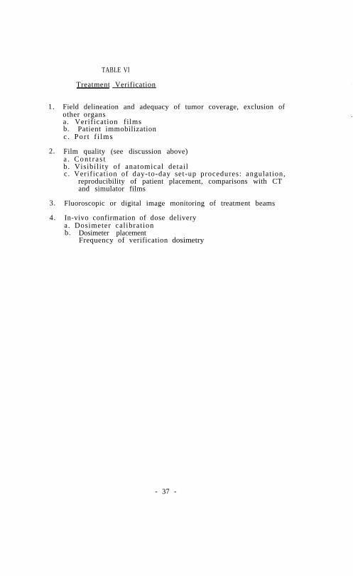
TABLE VI
Treatment Verification
1. Field delineation and adequacy of tumor coverage, exclusion ofother organsa. Verification filmsb. Patient immobilizationc . Por t f i lms
2. Film quality (see discussion above)a . Con t r a s tb. Visibil i ty of anatomical detailc. Verification of day-to-day set-up procedures: angulation,
reproducibility of patient placement, comparisons with CTand simulator films
3. Fluoroscopic or digital image monitoring of treatment beams
4. In-vivo confirmation of dose deliverya. Dosimeter calibrationb. Dosimeter placement
Frequency of verification dosimetry
- 37 -
CHAPTER 6
BRACHYTHERAPY
INTRODUCTION
Brachytherapy is a method of radiation therapy in which encapsulated sources areutilized to deliver radiation within a distance of a few centimeters by surface,intracavitary, or interst i t ial applications. The focus of this therapy is to enhancetumor sterilization while minimizing damage to normal tissue structures. There are, ofcourse, many complex, multi-variate factors that affect tumor and normal tissueresponse. However, a number of advantages are provided by brachytherapy applications.These include more. precise localization of dose, attaining distributions which conformto irregular tumor shapes, and potentially lover morbidity. In addition, thedevelopment of new techniques, the use of radium substitutes, and the improvement ofafter-loading devices have stimulated renewed interest in brachytherapy.
It is the purpose of this chapter to establish basic criteria for the descriptionand calibration of sealed sources, to suggest procedural policies for the developmentof a quality assurance program, to comment on approaches to treatment planning, and todiscuss general aspects of radiation protection. This chapter discusses use of radiumand its substitutes for temporary or permanent interstitial or intracavitaryapplications. The use of internally administered radionuclides or strontium-90 eyeapplicators is not described in this chapter but can be studied elsewhere [57].
SEALED SOURCES
A. Description
The accuracy of source calibration and of absorbed dose calculations inbrachytherapy applications depends, in part, on a detailed description of theradioactive sources. Therefore, it is incumbent upon the user to obtain thisinformation and to evaluate the potential implications for clinical dosimetry. Ingeneral, this information is available from the manufacturer or from the literature.
1. Physical and Chemical Form
The chemical composition of the radionuclide (e.g., Cs-137 adsorbed onto ceramicmicrospheres, radium sulfate, etc.) and inert filler material should be known alongwith information on the physical characteristics of the material (e.g., density,effective mass energy-absorption coefficient, etc.). This information is useful for anumber of reasons. F i r s t , although chemical instability and physical changes within asource are unlikely and are the responsibility of the manufacturer, the possibility ofsuch changes and the potential effects on patient treatments during the useful life ofa source should not be ignored. Second, dose correction for attenuation due to theself-absorption within a source may be desired although the effect is generally quitesmall [119]. Third, the presence of radioactive impurities should also be known.Some sources (e.g., Ir-192) require a storage period after initial production to allowthe decay of abort-lived impurities [127]; users should ask the manufacturer if suchprocedures are followed. Finally, if the source should rupture, knowledge of thechemical form may aid in radiation safety considerationa.
- 38 -

2. Source Encapsulation
Since the source encapsulation can influence source calibration, dosedistribution, and source integrity. detailed knowledge of its configuration andcomposition is important for the overall accuracy of clinical dosimetry. Suchinformation should be available from the manufacturer. Encapsulation designs may varyfor the same radionuclide for different manufacturers as well as for differentradionuclides. Most long-lived sources (Ra-226, Cs-137) are doubly encapsulated;other sources (Au-198) are singly coated, and others have a unique capsule design(I-125). The effect of the encapsulation on dose distributions of various sources hasbeen investigated by a number of authors both experimentally and theoretically and areavailable in the literature [35,40,67,73,119].
3. Radionuclide Distribution and Source Uniformity
The distribution of radioactive material within the encapsulation may becontinuous or in compartments or cells [119]; the loading of radionuclide along asource may be uniform or non-uniform, by design or otherwise; the active length may ormay not be centrally located along the source [123]; the wall thickness of thecasing may be non-uniform in different areas. There intricacies need to be consideredfor each type of source and their implications relative to source calibration and dosedistribution carefully assessed. Autoradiography of a source is a simple andinformative test; gross non-uniformity of the radionuclide within the source is easilyvisualized. For radioactive seeds or grainsneeds to be assessed [74].
, the uniformity of activity among seedsThe spacing of seeds in ribbons as provided by the
manufacturer may require monitoring.
4. Source Identification
Correct identification of sources of the same radionuclide and capsule design butof different activities is essential. Ease in such identification will prevent errorsrod reduce the level of personnel exposure and anxiety. At present, markings onsources are frequently difficult to read; color coding fades or disintegrates withtire, and repeated handling of color sutures tied to needles causes loss ofeffectiveness with age. The user must work with the manufacturer to devise anacceptable identification system which is simple, easy to read and long lasting.
- 39 -

B. Calibration of Brachytherapy Sources
1. Introduction
Unlike external beam radiation therapy , where the physicist relies on a properlycalibrated radiation measuring device (ion chamber) for his standard, in brachytherapythe physicist should rely on a properly calibrated standard radioactive source and onlyto a lesser extent upon his radiation measuring device. Clinical sources are thencalibrated by intercomparison with a standard source. This concept may differ frompresent practice, which tends to rely upon the source manufacturer’s calibration, orupon calibration factors of a well ionization chamber provided by the chambermanufacturer.
2. Calibration Instrument
Since the radioactive source is the standard, almost any reliable radiationdetector will serve as a calibration device. The most common device used is a wellionization chamber (re-entrant chamber) commonly known as an isotope calibrator, foundin virtually every nuclear medicine department. The second alternative is to use alarge volume (preferably 100 cm3 or larger) air ionization chamber to measure theradiation intensity at some distance (preferably 25 cm or greater) from the source.Other detectors or techniques might also be usable.
The reproducibility of this measuring device should be better than ±2%. Thesignal-to-noise ratio should not, therefore, be less than 100:l. This may not beobtainable when trying to measure at a distance of 25 cm or more with a large-volumeion chamber. In addition, it is essential to be able to accurately reproduce thepositioning of the standard source and all clinical sources to be measured. For suchmeasurements it is obvious that the relative distance from the source to the center ofthe detector must be maintained (at 25 cm distance, a 2 mm positioning error translatesto a 1.6% error in dose). In addition, because of oblique transmission through thewall of the source and the fact that most large volume ion chambers experiencesignificant directional dependence, the relative orientation of the source axis andchamber axis is also important. Plastic devices can be used to rigidly hold thechamber and the source in a fixed orientation at a fixed distance from each other.Such devices made from plastic form minimize scatter and are convenient to fashion.Devices made from rigid plastics on the other hand provide greater structuralintegrity.
The sensitivity of a well-type chamber is also dependent upon the position of thesource within the well and upon the orientation of the source [136]. It isessential, therefore, to devise a source holder which will reproduce the positioning ofa particular type of source from day to day and/or from source to source. A devicefrequently used is a small diameter plastic tube (perhaps 6 mm OD) cementedperpendicular to the center of a plastic plate which site on top of the well and isdesigned to center the tube in the well. The source is confined then to stand on endalong the axis of the well with the bottom end preferably a small distance (several cm)from the bottom of the well. Flexible sources such as seed assemblies or wire can beconfined by a helix situated equidistant from the wall of the well a short distancefrom the bottom.
3. Chamber Characteristics
Since a well-type chamber is the preferred measurement device, further discussionis specific for a well-type chamber. Similar problems exist for at-a-distance devices;the solutions, however, may differ.
- 40 -

The physicist should identify a single chamber system that will be used forbrachytherapy calibration. This need not be the role use of this chamber. Prior tousing this chamber for source calibration the electrical and radiologic characteristicsof the chamber must be established, including:
a. Scale factors and l inearity: In order to minimize the potential forundetected changes in the electrical characteristics of the chambersystem, it is recommended that a single scale and/or a single radionuclidesetting be used at all times irrespective of the number and types ofradionuclides calibrated, even for those devices where a radionuclide canbe selected by plug modules, dial setting, or push button. When it isnecessary to change scales or electrometer settings, the various scalesand other settings must be referenced to the usual setting by comparisonwith the same source for the two settings. The linearity of all scalesused should be verified.
b. Ion collection efficiency: Since all of these devices have large volumes,the ionization collection efficiency of the chamber should be determinedusing the highest intensity source expected to be calibrated. Techniquesusing measurements at two or more polarizing potentials should be used[39].
c. Geometry and length dependence: The dependence of the sensitivity of thechamber on the position of the source within the chamber and on the lengthof the source must be measured. A source should be moved about in theactive volume of the chamber to verify and quantitate the extent of thesensitivity change. Two techniques to determine the dependence on sourcelength have been described [17]. They involve either moving a shortsource throughout the region to be occupied by longer sources andintegrating the sensitivity over these rub-regions or obtaining a longsource (wire or seed assembly) and making measurements as the source isphysically shortened.
d. Thickness of the wall of the source: Sources of the same radionuclidewith significantly different encapsulation should not be consideredequivalent. The sensitivity of the chamber may change as a result ofdifferent thickness or type of wall around the source. This is dueprimarily to differences in the oblique filtration [137].
e. Energy Dependence: The sensitivity of a chamber will probably showsignificant dependence (>10%) on the energy of the photons even for“air-equivalent” or “tissue-equivalent” chambers. This dependence isapparently due to absorption of photons in the walls of the chamber,forward and backscattering of the photons and electrons from the walls ofthe chamber, and oblique transmission through the source.
4. Calibration of Sources
a. Long-lived sources (Ra-226, Cs-137. Co-60, etc.):
i) For each radionuclide (and encapsulation) to be measured, onesource should be identified as the standard source. The sourceshould be marked or otherwise identified so that it can berecognized at a later date. It is not necessary to remove thissource permanently from clinical use.
- 41 -

ii) Send this standard source to an appropriate calibrationlaboratory for calibration. At the present time, only theNational Bureau of Standards (NBS) provides these calibrations.However, efforts by the AAPM to establish other calibrationcenters are underway.
iii) Use the standard to calibrate all other similar sources.Calibration should be by sequential placement of the standardsource and the sources to be calibrated in the same geometrywithin the chamber and comparing readings. Although thistechnique minimizes the hazards of chamber failure, it isadvisable to predict the intensity of the standard source fromprevious measurements and compare the predicted measurement withthat actually observed. Serious deviations might suggestequipment malfunction.
b. Short-lived sources (Ir-192, Au-198, etc.):
i) Identify a long-lived source as your reference source. Thissource should be marked or otherwise identified so it can beidentif ied at a later date. This source may be a standard sourcefor another radionuclide.
ii) Obtain a standard source of the appropriate short-lived isotope.The standard source should be compared with the reference sourceby sequential placement within the chamber with identical chambersettings in the two cases. This intercomparison will be used toestablish a baseline comparison of the relative sensitivity ofthe system to the two sources.
iii) Submit the standard source to a suitable calibration laboratoryfor calibration.
iv) There are two techniques commonly used then to transfer thecalibration.
(1) The chamber is calibrated with the standard source and thereference source is used to verify that the chamber isoperating properly after the standard source has decayedaway. This requires temperature and pressure corrections toreference conditions if unpressurized, ambient air chambersare used.
(2) A correction factor defined as the ratio of two measurementsof chamber response using the standard source and referencesource is calculated. The correction factor relates theresponse of the chamber to the abort-lived standard sourcein terms of the response to the reference source.
v) In either case, the reference source is measured every time thechamber is used to calibrate the short-lived sources.
vi) The standard source need not be replaced when it decays to alevel much that it can no longer be used to calibrate thechamber.
- 42 -
C. Routine Surveillance Program
Treatment with sealed sources necessitates a quality assurance program which isquite different from an external beam program. For brachytherapy, the qualityassurance program must address the two components of the treatment objective: (1)achieving an optimal therapeutic effect while, (2) minimizing unwanted exposure tothe patient, radiologic personnel, and the general public. With regard to thelatter, many documents have been established for the safe use of sealed sources incancer management. It is imperative that the medical physicist be aware of theexistence and importance of local, state, federal, and international guidelines andregulations. Many of these are referenced in Chapter 7.
One cannot, of course, clearly separate the above two components in a qualityassurance program. However, with regard to optimizing the desired therapeuticeffect in brachytherapy, the program should primarily address the following broadcategories:
1. source integrity2. source calibration
4:3. implantation equipment
treatment planning and evaluation
The precise details should be tailored to the facility, to the type ofradionuclide, and to the clinical application. The following list provides a focusabout which the physicist can formulate an appropriate routine surveillance program.
1.2.
3.4 .5.6.7.8 .9.
10.11.12.
Order information and source acquisitionReceipt of radioactive materialsa. package monitoringb. review and corroboration of shipping memoAssay of sources (see Section above on sealed source calibration)Leak testing as required [98]Maintenance and inspection of implanting equipmentSterilization of equipment and sources as necessary [98]Control of source movement in and out of the radioactivity storage areaReview of implant procedures and techniquesSource removal from patient and return to storageImplant dosimetry (see Section III)Source inventory and disposalEducation of personnel
In addition, less frequent review of the work facility, transport devices.mechanical and electrical stability of calibration and surveying equipment, and thedetails of the implanting procedures themselves are also required.
TREATMENT PLANNING AND DOSE EVALUATION
A. Planning
The medical physicist must be prepared to advise the radiotherapist regardingbrachytherapy source configurations which will achieve the specified dose distri-bution. He should encourage the radiotherapist to develop clinical objectives interms of dose distribution and to make use of physics assistance in treatmentplanning.
- 43 -
Familiarity with traditional manual methods of dose calculation, e.g., theHanchester (or Paterson-Parker) system [87] and the Quimby system [34], isessential for understanding basic treatment planning approaches and for a basis ofcommunication with the physician. Also, computer calculated done-planning tableshave been published which may be useful for interstitial seed implants [70,118].
In certain individual situations it is possible to perform pre-implantcalculations for idealized source configurations proposed either by the physician orthe physicist. While this approach is undoubtedly useful for special or unusualcases, it is generally not recommended as a routine treatment planning procedure forindividual patients. A more efficient application of computers to implant treatmentplanning involves performing calculations and dose evaluations for a wide range ofidealized implants defined by systematic variations in dimensional and activityparameters [12,107]. Dose as a function of these parameters can then be presentedin the form of a table, graph or nomogram for individual treatment planning.
Definitive permanent implants with I-125 seeds require special consideration,because their planning, from the time of early clinical trials, has involved makingthe implanted activity a function of the average dimension of the treatment region[37]. Specialized planning is also required for boost therapy applications ofI-125 [13].
For intracavitary brachytherapy, source locations are generally determined bythe geometry of the applicator, and treatment planning connotes selection of asource-strength configuration which minimizes dose to normal tissue for a given doseto specified treatment location*. Optimization of this sort may be attempted bytrial and error or on the basis of intuition and clinical experience, but it isgreatly facilitated by computer calculations using appropriate algorithms [114].
B. Localization
Orthogonal films afford greater localization accuracy than films at otherangles. Certain precautions are required, however, to realize the potentialaccuracy. It is important that the origin of the coordinate system for each film beselected at a point such that the line joining it to the x-ray source isperpendicular to the film. Otherwise, an “origin offset” error results, which has ashearing effect on implant shape and may easily translate extreme source positionsby several millimeters for implant dimensions of a few centimeters.
For implants having source positions at significantly different distances fromthe x-ray tube target, demagnification calculations will distort the sourceconfiguration if a single magnification value is assumed. Individual magnificationcorrections at source positions are desirable for such implants and are madepossible by an “enhanced” ring method [88], in which the ring must be in the sameposition on the patient for both the AP and the lateral film and must, of course, becompletely imaged in both films.
For I-125 seed implants, it generally has not been practical to use orthogonalfilm localization if computerized isodose distribution6 are required. In mostcases, the seeds are too numerous and too close together to permit accurateidentification of seeds between orthogonal films. Therefore, a method often usedhas been stereo-shift localization, in which either the x-ray tube or the patient isshifted (usually longitudinally) a measured distance between two AP films [11].
- 44 -

Three-film localization, in which seed coordinates from an intermediate-anglefilm are used to assist in identifying images between two orthogonal films, isshowing promise of improved accuracy for both localization and identification[10,115,126]. Patient motion between films, for any localization method, isprobably the greatest source of error; it can be reduced by improving patientcomfort and by shortening the time between films.
C. Dose Calculation
Several computational options exist for the basic dose calculation involvingone point of interest rod one source. In one option the dose in the source vicinityis obtained by evaluating l II analytical expression involving the accumulatedactivity (integral of activity over t ine of treatment) , the exposure rate constant,the f-factor (for converting exposure to dose), encapsulation filtrationcorrections, geometric attenuation, and a (usually polynomial) functionalrepresentation of scattering buildup and exponential attenuation by tissue [120].The filtration corrections for linear sources would employ Sievert integralcalculations, and the tissue attenuation buildup corrections may be taken fromeither measured or calculated data. In another option, one may calculate theabsorbed dose rate from the measured exposure rate at unit distance. In a thirdoption, one can use the results of direct measurements of the dose rate per unitexposure at unit distance, or dose rate per unit nominal activity, for the sourcetype of interest within an appropriate phantom. For the two last options,information about the exposure rate constant and the activity are unnecessary.Greater confidence results from more than one approach, provided acceptableagreement is obtained in the region of interest. A reasonable goal is ±5%uncertainty in the data at points less than 2 cm from the source, where accuracy isof greater inportance than at more distant points.
Whether calculated or measured data are used, one has the further option ofassessing the data either by evaluating a (perhaps fitted) analytical expression orby interpolating from a table. Formula evaluation may involve regions of poor fitto the data and tends to require more computer time, whereas table look-up eitherrequires an inconveniently large table for direct look-up or tile-consuminginterpolation formulas if the table is to be small. An approach intermediatebetween there extremes is to use linear interpolation of a small table from whichgeometric variation has been removed. The geometric attenuation is re-inserted inthe calculation following table look-up [88].
In multiple source dose calculations at an array of points, it is highlydesirable to be able to calculate dose on a rectangular mesh (e.g., 0.5 cm width) inany plane of interest passing through the implant. One should be able to obtainmultiple parallel planes at specified separations at any given orientation.
It is also helpful for some purposes to be able to calculate both the volumeand the integral dose enclosed by isodose contours in three dimensions.
In implementing new or unfamiliar computer programs for brachytherapy dosecalculations, i t is advisable: (1) to compare results for an idealized (e.g.,single source) configuration with the results of band calculations, and (2) tocompare results for one or more typical clinical applications with those obtainedusing an established computing system, perhaps at another institution.
- 45 -
D. Evaluation
The items to be included in a typical evaluation will depend strongly onclinical requirements. However, it is essential that appropriate labelling ofisodose rate curves, date and time of implant, patient orientation and other patientdemographic information be clearly indicated. It may also be useful to superimposeisodose rate contours on AP and lateral films of the implant to indicate anatomicalrelationships.
If dose objectives have been specified for the treatment, the physicsevaluation should report a comparison of the doses desired at certain points ofinterest with those actually achieved. With respect to intracavitary applicationsfor cervix cancer, for example, comparison might be made at treatment pointsrepresenting the cervix and the obturator nodes , in addition to specific referencepoints and various tissue-tolerance points. Isodose contours for cervix treatmentsshould be displayed in planes intersecting, as nearly as possible, the centerline ofthe uterus.
For removable interstitial implants of wires or reed in ribbons, it is usefulto present isodose rate contours in regularly spaced planes perpendicular to thesource lines. The radiotherapist can thus easily identify the dose rate for whichthe contour adequately encompasses the region to be treated.
For permanent seed implants, it may be useful to determine an averageperipheral dose, i.e., the average dose on the surface containing the outermostseeds. This evaluation may not require computer isodose calculations and can bemade from graphs showing activity per unit l absorbed dose as a function of volumedimensions [134]. Perhaps a more useful clinical evaluation is to determine a“matched peripheral dose (MFD)” - the dose for which the isodose contour volumeequals the volume of the treatment region designated by the radiotherapist. If thetreatment region has been specified by mutually perpendicular dimensions, its volumeis usually calculated on the assumption of an ellipsoidal shape, since isodoses aswell as implanted anatomical structures generally have rounded contours. Reportingthis type of MPD as a quality control parameter has the virtues of (1) reducing awealth of computer data to a single number, and (2) the clinical feedback element ofrelating the dote to direct anatomical measurements by the radiotherapist.
Finally, in any brachytherapy evaluation, a treatment summary should beincluded which specifies the relevant treatment parameters. The report shouldcontain the basic physical aspects of the radioactive material (radionuclide, form,ac t i v i t y ) , source insertion and removal times or treatment dose rates for temporaryimplants, treatment volume and dome, high or low dose volumes, and critical tissuedoses.
REMOTE CONTROLLED, HIGH-INTENSITY BRACHYTHERAPY IRRADIATORS
Low dose rate afterloading systems employ various radioactive source materialsfor the treatment of many gynecologic, head and neck, and soft tissue malignancies.However, this approach requires patient hospitalization during the procedure andalso involves exposure to those attending the patient in the hospital room. Thesetwo problems are alleviated by a system which uses remotely controlled afterloadingof high intensity sources. Because of the high activity of the sources (l-9curies), these irradiators require special consideration with regard to their use.
- 46 -

A. Source position.
1. Daily tests should be conducted to verify the operational condition ofdevice. which indicate source location, e.g., light indicator. on thecontrol panel and a radiation monitor within the treatment room.
2. The reproducibility of physical positioning of the source within thecatheter should be within ±l mm and checked daily. This check may be donewith an autoradiographic technique.
3. The treatment position of the source must be verified to be at theprescribed position for each treatment course. This is normally done byconventional x-ray localization.
B. Treatment time.
1. Timer accuracy must be verified monthly. The timer should not result in anerror greater than 1% of the desired dose to be delivered.
2. The error in dose due to source travel time after occurrence of timer ON,and for complete return after timer OFF, should be determined initially andsemi-annually. This correction should be used in all instances where anerror of more than 1% might be introduced into the delivery of theprescribed dose.
3. In those cases where a back-up timer is not a standard feature of theirradiator , an accessory back-up timer should be provided.
4. The calculation of the treatment time should be verified independentlybefore the start of treatment.
5. The dose prescription may have to be modified because of the higher doser a t e .
C. Treatment confirmation.
1. At the time of each treatment during the course of therapy, radiographic orfluoroscopic confirmation of the applicator position should be made. Invivo dosimetric confirmation is l also recommended.
2. Constant patient viewing from the console must be available.
D. Emergency procedures.
Each installation must have a permanently posted operation plan foremergency source retraction should power or mechanical failure of the apparatusrequire such action. In all such installations, a person who has been trainedfor and has practiced the required action should be on duty whenever thisapparatus is used for patient treatment.
- 47 -

RADIATION SAFETY
INTRODUCTION
The purpose of this section is to outline a quality assurance (QA) programpertinent to the establishment and maintenance of an adequate health physics programin radiation therapy. The established procedures for the safe use of therapeuticand diagnostic equipment in a radiation therapy departments are described innumerous documents published by both the ICRP and the NCRP. Furthermore, many ofthese guidelinea have been adopted as laws by federal and state authorities (such asrules from the Nuclear Regulatory Commission and Agreement State Regulations). It isthus imperative that the medical physicist in charge of installation planning, com-missioning, mod maintenance of therapeutic equipment be aware of the existence andimportance of these guidelines and regulations.
The radiation protection program should be designed to cover all sources ofradiation and be consistent with regulatory requests and ALARA (As Low As isReasonably Achievable) concepts [19,48,130,132]. The program should be reviewedby the administration on a periodic basis to determine if adequate resources areavailable for its implementation. All aspects of the program must be welldocumented.
For the purposes of this report, we have defined the quality assurance programto consist of all the health physics components requiring periodic action. Thefollowing areas have been identified.
Personnel Dosimetry
1. Calibration of dosimeters by suppliersa. Instrument calibrationb. Source calibration
2. Calibration checks by usera . Instrument calibrationb. Source calibration
3. Distribution and use of badgesCalibrations and tests
4. Record keeping, reporting and review
Radiation Survey: The calibration and operating conditions of importance for aradiation survey of a radiation therapy facility are as follows [49,95,100,101].
1. Consult facility design for orientation of the beam relative topermanent attenuating objects.
- 48 -
2. Working conditions.a) Restrictions of beam orientationb) Work loadc) Occupancy factor, Use factor
3. Instrumentationa) Instrumentation calibration [51,101,130]b) Source calibration [99]
4. Interlock check
5. Reporting of survey results.a) Exposure rate versus locationb) corrective measures required
The structural shielding and installation of external beam equipment should beplanned and supervised by an expert knowledgeable in the methods of making shieldingcalculations. There must be related to the equipment specifications, radiationprotection requirements and regulations.
Upon completion, an installation must have a radiation survey made by or under the supervision of a physicist familiarwith health physics techniques. The parameters used for the shielding design must be fully understood by the surveyor foraccurate assessment of the results. For example, if the exposure rate in an area occupied by personnel exceeds the maximumpermissible value, recommendations for changes should be made with due regard to normal and extreme operating conditions.Therapy equipment, generating X-rays above 10 MeV, is a potential source of high energy neutrons, which are rnostly gener-ated in the target and collimators in the treatment head. The neutron fluence can contribute significantly to the radiationlevels in areas adjacent to the therapy machine. Radiation surveys of neutrons must therefore be considered around high ener-gy therapy machines [51, 101]. The installation survey and following periodic surveys shall be documented and filed forfuture review and use.
A comprehensive review of maximum permissible organ doses and ALARA principlesis given in references 19,48,99, and 130.
Radiation surveys should be repeated every time a change in the installation orthe working conditions occurs. In particular, workload, use factor, and occupancyshould be reviewed. Any changes should be documented and followed by a radiationsurvey. Periodic and frequent checks of door interlocks and beam orientationconstraints must also be performed. The calibration of survey instruments isdiscussed in [51,101].
The surveying physicist shall report the results to the person in charge of theequipment and keep copies of such reports on file. It is important that proceduresand adequate report and data forms be developed and documented to facilitateconsistent and accurate periodic surveys.
Below is a suggestion of suitable documents which should be written by aqualified health, medical, or radiological physicist using the Bibliography. Suchdocuments should give due regard to the unique working conditions of the particularradiation therapy department for which they are intended.
Radiation safety rulesALARA radiation levels for radionuclide sourcesShielding calculationsProcedure for door and beam orientation interlockchecksInventory of radiation survey equipmentSource inventory and disposal records
- 49 -

Calibration procedure for radiation survey monitorsEmergency procedure for 1) Co-60 equipment
2) brachytherapy (breakage, loss)3) linacs and other types of teletherapy equipment
In relation to the above, the FDA Problem Reporting Program for RadiationTherapy Devices indicates that a Co-60 source which jams in the unshielded ‘on’,position in not an infrequent occurence. The emergency response should be practicedperiodically so that the reaction to such an incident is instinctive.
Brachytherapy (See also Chapter 6)
Categories requiring radiation safety measures in brachytherapy.
A . F a c i l i t y
1. Receipt and inventory of sources2. Storage and work areas (shielding, carrier design)3. Transportation (shielding, carrier design)
1. Inventory2. Source identification3. Cleaning (especially safety aspects)4. Leak tests5. Disposal
C. Clinical Application
1. Preparation, l sterilization and transfer of l sources andsource applicator
2. Application to patient3. Removal of sources from patient (patient and room
surveys)4. Return of sources to storage area5. Personnel monitoring6. Patient discharge
D. Emergencies and Special Precautions
1. Source breakage and contamination2. Loss of source3. Cardiac or respiratory arrest4. Emergency surgery5. Death of patient (autopsy, cremation, embalming.)6. Notification of the location of radioactive sources to local fire
department.
E. Education and Training. of Personnel
1. Physician and nursing staff2. Ancillary personnel (including housekeeping)
- 50 -

In the present state of our knowledge, it is considered wise to avoid allunnecessary irradiation. Patients treated by brachytherapy techniques present thegreatest potential radiation hazard since the sources used contain photon emittersof relatively high intensities and have the potential of being misplaced in anunshielded configuration. Reduction of radiation exposure to personnel frombrachytherapy sources may be achieved by one or any combination of the followingmeasures: (a) increasing the distance of the individual from the source, (b)reducing the duration of exposure and (c) using protective barriers between theindividual and the source. The principle of keeping exposures as low as isreasonably achievable (ALARA) applies, of course, to the application of internallydistributed radioactive waled sources.
There are many good references available on radiation safety in brachytherapy,most notably the reports of the National Council on Radiation Protection andMeasurements [96,98,99]. The recommendations of these references are not repeatedhere, but the reader is provided with a list of procedures in brachytherapy wherethought must be given to radiation safety. Naturally, any measure taken by thestaff to reduce the risk to personnel and to maximize the benefit to the patient isnot only radiation safety, but is intimately connected to the quality assuranceprogram as well. Further, each facility must consult the agency regulations(Nuclear Regulatory Commission or State) for any specific requirements on radiationprotection pertinent to its license to possess and use radioactive materials andradiation equipment.
Conclusion
The rationale of a radiation safety program in radiation therapy is adequatelycovered by the numerous reports issued by ICRU, ICRP, NCRP, federal and localagencies. The operational procedures discussed in this section and the extensivebibliography should facilitate the selection of the correct procedures, qualityassurance items and frequency of procedures for most radiation safety problems.
The physicist in charge of the radiation safety program must document allprocedures and the results of all surveys and checks. This assures consistency,safety, and accuracy. It gives credibility to the health physics program. However,it should be emphasized that radiation protection principles are undergoing acontinuous review by many regulatory agencies and professional organizations. I t i sthus necessary for the physicist to follow there developments.
Furthermore, it should be emphasized that if a medical physicist finds himselfinvolved into an area in which he is unqualified, for example, accelerator radiationsafety, he should consult a qualified expert in that particular area for assistance.
- 51 -

APPENDIX A
QUANTITIES AND UNITS IN TELETHERAPY AND BRACHYTHERAPY
At the time of writing, the world of science is in the process of adopting theInternational System of Units (SI, for Systeme International). The InternationalCommission on Radiation Units and Measurements (ICRU) now uses both SI and specialradiation units in its reports and plans to discontinue the use of the specialradiation unite by the end of 1985. The reason for changing to SI radiation unitsis that the special radiation units (rad, roentgen, curie) are not coherent withother units of the modernized meter-kilogrm-second-ampere system of units, i.e.,their use introduces unnecessary numerical factors into the relationships betweenthe numerical values of physical quantities. The most common physical quantitiescurrently of importance in teletherapy and brachytherapy, with their SI andcustomary or special units, are given in the attached table, with some relevantconversion factors.
The change to SI units will necessarily involve some inconvenience. For thequantity absorbed dose, the change from rads to grays is not difficult, and can bemade even easier by using the convenient equality of the centigray (cGy) and therad. The quantity exposure has the inconvenient SI unit coulomb per kilogram(C/kg), and the SI unit of exposure rate can take a variety of even moreinconvenient forms. In order to facilitate the change to SI units, several Europeancountries have changed from the quantity exposure to the quantity air kerma. Thesubject is under consideration in the U.S., and a recommendation whether to changefrom exposure to another quantity will presumably be made by suitable authorities.Until a decision has been made, it is probably advisable to continue use of thespecial unit of exposure, the roentgen (R), even when, as for example in teletherapycalculations, all other quantities are given in SI units.
In brachytherapy dosimetry, there will be still another inconvenient change.from the usual multiple of the special unit of activity, the millicurie (mCi), to amultiple of the SI unit of activity, the megabecquerel (MBq). However, in additionto problems associated with the change of units, a change has been proposed to wetstill another problem in brachytherapy dosimetry. Brachytherapy sources other thanradium have conventionally been specified in terms of exposure rate at a specifieddistance. (Radius sources are both specified and calibrated in terms of mass ofradium, but radium now plays a decreasing role in brachytherapy.) Both the sourceactivity A and the exposure rate constant Γ δ enter into brachytherapy calculations,but in such a fashion that only the product A ⋅ Γδ influences the calculated tissuedose rate. Since A ⋅ Γδ is the exposure rate at unit distance, it is clear that theactivity A and the exposure rate constant Γ δ are variables whose separate valuesare irrelevant to source specification. As a result, it has been repeatedlysuggested that brachytherapy sources be specified in the same terms in which theyare calibrated, i .e . , exposure rate at 1 meter [40,127].
Because of these impending changes, it is of great importance in brachytherapycalculations that all possible care be used in calculating tissue dose from thespecified source strength. Methods of calculation now in use will almost certainlybe changed to some extent in future years, and each change holds the possibility ofserious error. Where methods of calculation are well established, it would seemprudent to continue without change until wide agreement has been reached onquantities, units, and methods of source specification for brachytherapy.
- 52 -
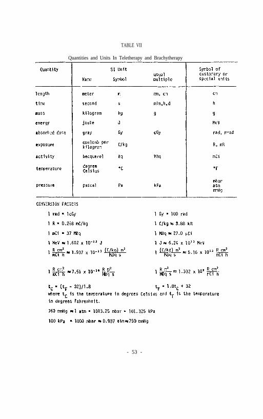
TABLE VII
Quantities and Units In Teletherapy and Brachytherapy
- 53 -
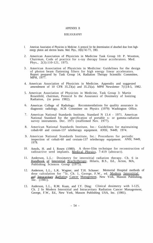
APPENDIX B
BIBLIOGRAPHY
I. American Association of Physicists in Medicine: A protocol for tbe determination of absorbed dose from high-energy photon and electron beams. Med. Phys., 10(6):741-771, 1983.
2. American Association of Physicists in Medicine Task Group 10: P. Wootton,Chairman, Code of practice for x-ray therapy linear accelerators. Med.Phys., 2(3):110-121, 1975.
3. American Association of Physicists in Medicine: Guidelines for the designof photon beam flattening filters for high energy linear accelerators.Report prepared by Task Group 14, Radiation Therapy Scientific Committee,MPH, 1977.
4. American Association of Physicists in Medicine. Appendix and suggestedamendment of 10 CFR 35.23(a) and 35.25(a). MPH Newsletter 7(1):4-5, 1982.
5. American Association of Physicists in Medicine, Task Group 3: MartinRosenfeld, chairman, Protocol fo the Assurance of Dosimetry of IonizingRadiation, (in press 1982).
6. American College of Radiology: Recommendations for quality assurance indiagnostic radiology. ACR Committee on Physics (1979) Washington Office.
7. American National Standards Institute, Standard N 13.4 - 1971. AmericanNational Standard for the specification of portable x- or gamma-radiationsurvey instruments. Dec. 1971 (reaffirmed Nov. 1977).
8. American National Standards Institute, Inc.: Guidelines for maintainingcobalt-60 and cesium-137 teletherapy equipment. ANSI, N449, 1974.
9. American National Standards Institute, Inc.: Procedures for periodicinspection of cobalt-60 and cesium-137 teletherapy equipment. ANSI, N449,1978.
10. Amols, H. and I. Rosen (1980). A three-film technique for reconstruction ofradioactive seed implants. Medical Physics, 7:419 (abstract).
11. Anderson, L.L.: Dosimetry for interstitial radiation therapy. Ch. 6 inHandbook of Interstitial Brachytherapy, Hilaris, B.S., Ed., Acton, MA,Publishing Sciences Group (1975).
12. Anderson, L.L., L.K. Wagner, and T.H. Schauer: Memorial Hospital methods ofdose calculation for 192Ir, Ch. 1, George, F.W., ed. Modern Interstitialand Intracavitary Radiation Cancer Management, New York, Masson Publishing,Inc. (1981).
13. Anderson, L.L., R.M. Kuan, and I.Y. Ding: Clinical dosimetry with I-125,Ch. 2 In Modern Interstitial and Intracavitary Radiation Cancer Management,George, F.W., Ed., New York, Masson Publishing USA, Inc. (1981).
- 54 -

14. Annett C.H.: Program for periodic maintenance and calibration of radiationtherapy linear accelerator;. Applied Radiology, November/ December 1979.
15. Att ix P.R. , and W.C. Roesch (ed): Radiation Dosimetry, 2nd edition Vol. II,, “Instrumentation,” Academic Press, NY, NY, 1966.
16.
17.
18.
19.
20.
21.
22.
23.
24.
25.
26.
27.
28.
Baily N.A., R.A. Horn, and T.D. Kampp: Fluoroscopic visualization ofmegavoltage therapeutic x-ray beams. Int. J. Radiat. Oncol. Biol. Phys.,6:935-939, 1980).
Berkley, L.W., W.F. Hanson, and R.J. Shalek: Discussion of the Results ofMeasurements with a Portable Well Ionization Chamber for Calibration ofBrachytherapy Sources in Recent Advances in Brachytherapy Physics, MedicalPhysics Monograph #7, New York, American Institute of Physics, 1981.
Bjarngard B.E., R.W. Piontek, and G.K. Svensson: Electron scattering andcollimation system for a 12 MeV linear accelerator. Med. Phys.,3(3):153-158, 1976.
Brodsky A.: Principles and practices for keeping occupational radiationexposure at medical institutions as low as reasonably achievable. Draftmanuscript, NUREG 0267, Office of Standards Development, US NRC, December,1977.
Campion PJ, J.E. Burns, and A. Wiliams: A code of practice for the detailedstatement of accuracy. National Physical Laboratory. Department of Trade andIndustry. Her Magesty’s Stationary Office, London, 1973.
Cohen, M.: The properties and dosimetry of radium substitutes. Proceedingsof the AAPM Summer School on Radiation Dosimetry, Burlington, VT (1976).
Cooper J.S., J. Newall, S. Kramer, W.E. Powers, L.W. Davis, D.F. Herring,and J. Sedransk: Measuring the quality of medical care: A beginning.Cancer Clinical Trials, 2(1):55-58, 1979.
Derzon R.A.: How will the net technologies affect medical care? Invest.Radiol. 14(3):62-66, 1979.
Droege R.T., and B.E. Bjarngard: Influence of metal screens on contrast inmegavoltage X-ray imaging. Med. Phys. 6:487-493, 1979.
Ege G.N., B.J. Cummings: Intersti t ial radio-colloid i l iopelviclymphoscintigraphy. Int.J.Rad.Onc.Biol.Phys. 6:1483-1490, 1980.
Ehrlich M. and P.J. Lamperti: Uniformity of high energy electron beamcalibrations, Phys. Med. Biol. 14(2):305-314, 1969. Also: Electron therapydosimetry, in Measurements for the Safe Use of Radiation, Nat. Bur. Stand.Spec. Publ. 456, U.S. Government Printing Office, 1976.
Essenburg A., and A. Koziarsky: Alignment of light localized beam andradiographic r-ray beam. Radiology, 104(3):716, 1972,
Feldman A., C.E. Almeider, and P.R. Almond: Measurement of electron beamenergy with rapid-processed film. Med. Phys., 1:74-76, 1974.
- 55 -

29. Fineberg H.V., and H.H. Hiatt: Evaluation of medical practices. The casefor technology assessment. N. Engl. J. Med. 301(20):1086-1091, 1979.
30. Fletcher G.H: Textbook of radiotherapy, Lea and Febiger, Philadelphia,pp.106-107, 1966.
31. Gagnon W.F., L.W. Berkley, P. Kennedy, W.F. Hanson, R.J. Shalek: Analysis Ofdiscrepancies encountered by the MPH Radiological Physics Center. Med.Phys., 5:556-560, 1978.
32. Geise R.A., and E.C. McCullough. The use of CT-scanners in megavoltagephoton-beam therapy planning. Radiology 124:133-141, 1977.
33. Glasser S.M., and T.G. Dehn: Reject film study. Cost and qualityconsiderations in a radiology department. QRB, 6(6):19-22, 1980.
34. Goodwin P.M.. E.H. Quimby, and R.H. Morgan: Physical Foundations ofRadiology, 4th ed., Hew York, Harper and Row (1970).
35. Gromadzki Z., C.C. Ling, S. Rustig, and J. Cundiff: Radiation fluenceanisotropy of 192 Ir and 198 Au seeds. Med.Phy. 8:570, 1981.
36. Hanson W.F., W. Grant, III, P. Kennedy, H.H. Cundiff, W.F. Gagnon, C.W.Berkley, and R.J. Shalek: A review of the reliability of chamber factorsused clinically in the United States (1968-1976). Wed. Phys., 5(6):553-555.1978.
37. Henschke U.K. and Cevc, P.: Dimension averaging a simple method fordosimetry of interstitial implants. Rad.Bio.Ther. 9:387-398, 1968.
38. Herring D.F., and D.H.J. Compton: The degree of precision in the radiationdose delivered in cancer radiotherapy. Computers in Radiotherapy, Br. J.Radiol. Special Report No. 5, pp.51-58, 1971.
39. Holt J.G., R.E. Stanton, R.E. Sell: Ionization Collection Efficiencies ofSome Ionization Chambers in Pulsed and Continuous Radiation Beams.Med.Phys. 5:107-110, 1978.
40. Horsler A.F.C., J.C. Jones, and A.J. Stacey: Cesium-137 sources for use inintracavitary and interstitial radiotherapy. Brit.J.Radiol. 37:385-390,1964.
41. Hospital Physicists’ Association: A code of practice for the dosimetry of 2to 35 MV x-ray and caesium-137 and cobalt-60 gamma-ray beams. Phys. Med.Biol. , 14(1):1-8, 1969.
42. Hospital Physicists’ Association: A suggested procedure for the mechanicalalignment of telegamma and megavoltage x-ray beam units. HPA Report SeriesNo. 3, 1970.
43. Hughes D.B., and C.J. Karzmark: Errors of physical data on radiationtherapy machines. Fourth Varian Users’ Meeting, Washington Univ., St.Louis, March 29-30, 1973.
- 56 -

44. Humphries L.J.: Dosimetric Instrumentation. MPH Workshop on ElectronLinear Accelerators in Radiation Therapy II, 1981.
45. Ibbott G.S., J.E. Barnes, G.R. Hall, and W.R. Hendee: Stem corrections forionization chambers. Med. Phys., 6(2)328-330, 1975.
46. International Atomic Energy Agency: Physical Aspects of radioisotopebrachytherapy, IAEA Report Series No. 75, 1967.
43. International Electrotechnical Commission: Draft - Medical electronaccelerators in the range - 50 MeV. Section IV, Performance TolerancesTechnical Committee 62., 1981.
40. International Commission on Radiation Protection: Implication of commissionrecommendations that doses be kept As Low As Reasonably Achievable. ICRPPublication 22, 1973.
49. International Commission on Radiation Protection: The handling, storage,use and disposal of unsealed radionuclides in hospitals and medical researchestablishments. ICRP Publication 25, 1976.
50. International Commission on Radiation Units and Measurements: Radiationdosimetry x-rays and gamma rays with maximum photon energies between 0.6 and50 MeV. ICRU Report 14, 1969.
51. International Commission on Radiation Units and Measurements: Radiationprotection instrumentation and its application. ICRU Report 20, 1971.
52. International Commission on Radiation Units and Measurements: RadiationDosimetry, Electrons with initial energies between 1 and 50 MeV. ICRUReport 21, 1971.
53. International Commission on Radiation Units and Measurements: Determinationof absorbed dose in a patient irradiated by beams of x- or gamma-rays inradiotherapy procedures, ICRU Report 24, 1976.
54. International Commission on Radiation Units and Measurements: Dosespecification for reporting external beam therapy with photons andelectrons. ICRU Report 29, 1978.
55. International Commission on Radiation Units and Measurements: Averageenergy required to produce an ion pair. ICRU Report 31, 1979.
56. International Commission on Radiation Units and Measurements: Radiationquantities and units. ICRU Report 33, 1980.
57. Johns H.E., and J.R. Cunningham: The physics of Radiology, 4th Edition.Charles C. Thomas, Publisher. Springfield, IL 1983.
58. Kaarls R. (rapporteur): Report of the BIPM working group on the statementof uncertainties. 21-23 October, 1980. Proces-verbaux du ComiteInternational des Poids et Mesures, 49, A1-A12, 1981 (in French). Englishversion available from R. Colle or R. Loevioger, National Bureau ofStandards, Washington, DC 20234.
- 57 -

59. Kartha P.K.I . , A.C. Bin, I. Wachtor, and F.R. Hendrickson: Accuracy inradiotherapy treatment. Int. J. Radiat. Oncol. Biol. Phys., 2:797-799,1977.
60. Karzmark C.J., and P.A. Huisman: A programmed maintenance system forcomplex radiological equipment. Br. J. Radiol. 38:474-475, 1965.
61. Karzmark C.J.: Some aspects of radiation safety for electron acceleratorsused for both x-ray and electron therapy. BJR, 40:697-703, 1966.
62. Karzmark C.J., P.A. Huisman, and D.C. Rust: Scheduling of radiologicalequipment maintenance and generation of archival records using amini-computer. Br. J. Radiol., 51:1026, 1978.
63. Karzmark C.J . : Concerning radiotherapy standard dose meter calibration.Med. Phys. 7(5):574-575, 1980.
64. Karzmark C.J.: Quality assurance for radiotherapy linacs. ProceedingsEighth Clinac Users’ Meeting, 62-63, 1980 Kuaui, Hawaii, June 31 - Feb 2,1980.
65. Kase K.R., G.J. Adler and B.K. Bjarngard: Comparison of electron beam dosemeasurements in water and polystyrene using various dosimeters. Med.Phys.1982. Med Phys 9:13-19, 1982. (Erratum: Med Phys 9:784, 1982).
66. Keithley Instruments, Inc.: “Electrometer Measurements," 2nd edition,March, 1977.
67. Krishnaswamy, V.: Dose distributions about 137 Cs sources in tissue.Radiology 105:181-184, 1972.
68. Ku H.H. (ed.): Precision Measurement and Calibration. MBS SpecialPublication 300. Vol.1. Washington DC 1969.
69. Lane R.G., D.D. Tolbert, B.R. Paliwal and R.R. Radtke: Radiation incidentswith cobalt-60 teletherapy unit. Health Physics 31, 163-165, 1976.
70. Laughlin, J.S., W.M. Siler, E. Holodoy, and F.W. Ritter: A dose descriptionsystem for interstitial radiation therapy. Amer.J.Roent. 89:470-490, 1968.
71. Lax I., and A. Brahme: Collimation of high energy electron beams. ActaRadiol., 19:199-207, 1980.
72. Lindstrom R: Part two: Implementing a shared quality assurance program.Dimens. Health Serv. 56(3):32-34, 1979.
73. Ling C.C., L.L. Anderson, W.U. Shipley: Dose inhomogeneity in interstitialimplants using 125 I seeds. Int.J.Rad.Onc.Phys.Biol. 5:419-425, 1979.
74. Ling, C.C., and Z.C. Gromadzki: Activity uniformity of 192 Ir seeds.Int.J.Rad.Onc.Phys.Biol. 7:665-669, 1981.
75. Linton O.W., W.S. Properzio, and J. P. Steele: Quality assurance: An ideawhose time has come. AJR 133(5):989-992, 1979.
- 58 -

76. Loevinger R., T.P. Loftus: Uncertainty in the delivery of absorbed dose.Proceedings of the International Course on Ionizing Radiation Metrology. E.Casnati, Ed., Editrice Compositori, Bologna, page 459, 1977.
77. Loevinger, R. (1981). “The role of the standards laboratory inbrachytherapy”, in Recent Advances in Brachytherapy Physics, AAPM MedicalPhysics Monograph No. 7, Douglas R. Shearer , ed., American Institute ofPhysics, New York.
70. Lutz W.R., R.D. Larsen, and B.E. Bjarngard: Beam alignment tests fortherapy accelerators. Int. J. Rad. Onc. Phys. Biol. 7 (1727-1731) 1981.
79. Maddox B.J., and K.R. Kase: Experience with feedback electronics used forcable-connected ionization chamber measurements. Med Phys 6:334, 1979
80. Marks J.E., A.G. Haus, G.H. Sutton, and M.L. Griem: The The value oftreatment verification fi lm in reducing localization errors in theirradiation of complex fields. Cancer 37:2755, 1976.
81. Massey J.B.: Manual of Dosimetry in Radiotherapy. IAEA Technical Reports,Series No. 110, 1970.
83. McCullough E.C., and Ana Maria Krueger: Performance evaluation ofcomputerized treatment planning systems for radiotherapy: external photonbeams. Int. J. Radiat. Oncol. Biol. Phys., 6:1599-1605, 1980.
84. McCullough E.C.: Computed tomography in radiation therapy treatmentplanning. (In) Radiology of the Skull and Brain, Vol. 5, ed. by H. Newtonand G. Potts, C. V. Mosby, St. Louis, 1981.
85. McCullough E.C., and D.H. Seujem: Airborne concentrations of toxic metalsresulting from the use of low melting point lead alloys to constructradiotherapy shielding. Med. Phys. 8:111, 1981.
86. Mellins H.Z. : ARRS presidential address: Accounting to society:Radiologic concern for patient care. AJR 130(2):221-222, Feb. 1978.
87. Meredith. W.J., ed.: Radium Dosage, The Manchester System, 2nd ed.,Baltimore, Williams and Wilkins Co. (1967).
88. Mohan, R. and Anderson, L.L.: BRACHY-II, Interstitial and IntracavitaryDose Computation Program User's Guide, New York, Memorial Dose DistributionComputation Service (Hay, 1980).
89. Moseley R.D. : International conference: The impact of new radiologicaltechnology on health care, research and teaching. Keynote address. Invest.Radiol. 14(3 suppl):2-4, 1979.
90. Moyer R.F.: Qualaity assurance of electron-beam energy using an aluminumwedge. Radiol . , 140:237-239, 1981.
91. Muller J.W. : Some second thoughts on error statements. Nucl. Instr. Meth.163(241-251)1979.
- 59 -

92.
93.
94.
95.
96.
97.
98.
99.
100.
National Council on Radiation Protection and Measurements: Recommendatoinsfor waste disposal of phosphorus 32 and iodine 131 for medical users NCRPReport No. 9, 1951.
National Council on Radiation Protection and Measurements: Safe handling ofradioactive materials. NCRP Report No.30, 1964.
National Council on Radiation Protection and Measurements: Radiationprotection in educations1 institutions. NCRP Report No. 32, 1966.
National Council on Radiation Protection and Measurements: Medical x-ray andgamma-ray protection up to 10 MeV - equipment design and use. NCRP ReportNo. 33, 1968.
National Council on Radiation Protection and Measurements: Precautions inthe management of patients who have received therapeutic amounts ofradionuclides. NCRP Report No. 37, 1970.
National Council on Radiation Protection and Measurements: Basic RadiationProtection Criteria. NCRP Report No. 39, 1971.
National Council on Radiation Protection and Measurements: Protectionagainst radiation from brachytherapy sources. NCRP Report No.40, 1972.
National Council on Radiation Protection and Measurements: Specification ofgamma-ray brachytherapy sources. NCRP Report No. 41, 1974.
National Council on Radiation Protection and Measurements: Structuralshielding design and evaluation for medical use of x-rays and gamma rays ofenergies up to 10 MeV. NCRP Report No. 48. 1976.
101. National Council on Radiation Protection and Measurements: Instrumentationand monitoring methods for radiation protection. NCRP Report No. 57, 1978.
102. National Council on Radiation Protection and Measurements: A handbook ofradioactivity Measurement procedures. NCRP Report No. 58, 1978.
103. National Council on Radiation Protection and Measurements Dosimetry of X-rayand Gamma-ray Beams for Radiation Therapy in the Energy Range 10 KeV to 50MeV. NCRP Report No. 69, 1981.
104. Naylor G.P., and P.C. Williams: Dose distribution and stability of ofradiotherapy electron beams from a linear accelerator. Brit. J. of Radiol.,45:603-609, 1972.
105. Nordic Association of Clinical Physics: Procedures in external radiationtherapy dosimetry with electron and photon beams with maximum energiesbetween 1 and 50 MeV. Acta Radiol. Onc. Biol. Phys. 19:55, 1980.
106. Perez C.A., et al.: Criteria for radiation oncology in multidisciplinarycancer management. Report to the Director of the NCI by the Committee forRadiation Oncology Studies (CROS), February 1981.
- 60 -

107. Pierquin, B., and D.J. Chasagne, C.M. Chahbazian, and J.F. Wilson:Brachytherapy, St. Louis, Warren H. Green, Inc. (1978).
108. Purdy J.A., D.J. Keys, and P.A. Parrino: A quality assurance program forradiation therapy treatment units. Presented at MPH Annual Meeting,Atlanta, Georgia, 2 August 1979.
109. Randall G.J., D.V. Henning, and J. G. Holt: Teletherapy Alignment: Asimplified method of quality control. Int. J. Radiat. Oncol. Bio. Phys.2:205-209, 1977.
110. Reinstein L.E., C.G. Orton: Contrast enhancement of high energyradiotherapy films. Abstract. Med.Phys. 5 (332) 1978.
111. Reinstein L.E.: CALGB, Cancer and Leukemia Group B, Proceedings of theworkshop on quality control in the radiotherapy department. New York, May31, 1979.
112. Richards M.J.S., and D.A. Buchler: Errors in reproducing pelvic radiationportals. Int. J. Radiat. Oncol. Biol. Phys., 2:1017-1019, 1977.
114. Rosenstein, L.M.: A simple computer program for optimization of sourceloading in cervical intracavitary applicators. Brit.J.Radiol. 50:119-122,1977.
115. Rosenthal, M.S. and Nath, R.: An automatic seed identification techniquefor interstitial implants using three isocentric radiographic views.Med.Phys. 8:570 (abstract), 1981.
116. Russell Z.: A comprehensive radiology quality assurance program. QRB96(6):15-18, 1980.
117. Samulski T., et al.: Radiation therapy dosimetry reviews by the Centers forRadiological Physics. Int. J. Radiat. Biol. Phys. 7 : 3 7 8 , 1 9 8 1 .
113. Rosenfield M. and D. Jette: Applications of redundancy in medical physics(submitted for publication in Med. Phys. 1982).
118. Shalek, R.J.. Stovall, M.A. and Sampiere, V.A.: The radiation distributionand dose specification in volume implants of radioactive seeds.Amer.J.Roent. 77:863-868, 1957.
119. Shalek, R.J. and Stovall, M.S.: The M.D. Anderson method for thecomputation of isodose curves around interstitial and intracavitaryradiation sources. I. Dose from linear sources. Amer.J.Roent.102:662-672, 1968.
120. Shalek, R.J. and Stovall, M.: Dosimetry in implant therapy, Ch. 31 inRadiation Dosimetry, Vol. III. Sources, Fields, Measurements and
(1971).Applications, Attix, F.H. and Tochilin, E. Eds., New York, Academic Press
121. Shalek R.J., P. Kennedy, M. Stovall, J.H. Cundiff, W.F. Gagnon, W. Grant,III, and W.F. Hanson: Quality assurance for measurements in therapy.Abstract. NBS SP456:111, 1976.
- 61 -

122. Shalek R.: Criteria for quality assurance programs in radiation therapy andlegal duty. In Proceedinga of a Symposium an Quality Assurance ofRadiotherapy Equipment. Ed. G. Sterkschall. MPH Symp. #3, Kansas City,MO, June 4-5, 1983.
123. Sharma, S.C., Williamson, J.F., Khan, F.M. and Jones, R.K: Dosimetricconsequence of asymmetric positioning of active source in 137Cs and226Ra intracavitary tubes. Int.J.Rad.Onc.Phys.Biol. 7:555-559, 1981.
124. Siddon R.L. : Solution to treatment geometry problems using coordinatetransformationa. Med. Phys., 8:766-774, 1981.
125. Siddon R.L., L.H. Chin and R.E. Zimmerman: Utilization of parasternallymphoscintigraphy in radiation therapy of breast carcinoma.Int.J.Rad.Onc.Phys.Biol. 8:1059-1063, 1981. 1982.
126. Smith, V.: Improved localization procedure for interstitial implants.Med.Phys. 7:438 (abstract), 1980.
127. Stephens, S.O.: 192Ir production quality assurance. Recent Advances inBrachytherapy Pysics, Medical Physics Monograph No 7, American Institute ofPhysics, New York 72-76, 1981.
128. Thompson D.L., et al.: Nationwide survey of Co-60 teletherapy: finalreport . Bureau of Radiological Health, HHS Publication (FDA) 80:8130,August, 1980.
129. Ting J.Y.: Protocol for verification of treatment planning programs.Available from Medical Systems Division, General Electric Company. P.O. Box414, Milwaukee, WI 53201.
130. U.S. Nuclear Regulatory Commission. Regulatory Guide 8.20. Applications ofbioassay for I-125 and l-131. Draft, April 1978.
131. U.S. Nuclear Regulatory Commission: Fed. Reg. 44:1724, No 5 - MondayJanuary 8, 1979.
132. U.S. Nuclear Regulatory Commission: Regulatory Guide 10.8. Guide for thepreparation of applications of medical programs. Revision 1, 1980.
133. U.S. Nuclear Regulatory Commission. Regulatory Guide 10.8 (Revision 1) Oct.1980, (Appendix D - Calibration of Instruments).
134. Waterman, F. and Strubler, K.: Absorbed dose determination forinterstitital I-125 boost therapy. Med.Phys. 7:437 (abstract), 1980.
135. White D.R.: The formulation of tissue substitute materials using basicinteraction data. Phys. Med. Biol. 22:889-899, 1977.
136. Williamson, J.P., Khan, F.M., Sharma, S.C. and Fullerton, G.D.: Methods forRoutine Calibration of Brachytherapy Sources. Radiology, 511-515, 1982.
137. Williamson, J.F., Marin, R.L. and Khan, F.M.: Dose Calibrator Response toBrachytherapy Sources: Monte Carlo and Analytical Evaluation. Med.Phys.10:135-140, 1983.
- 62 -

138. Wood R.G.: Computers in Radiotherapy - Physical Aspects. Butterworths andco . , London, 1974.
- 63 -