physical effects and consequences from ......physical effects and consequences from detonations and...
TRANSCRIPT
Munitions Safety Information Analysis Center Supporting Member Nations in the Enhancement of their Munitions Life Cycle Safety
Munitions Safety Information Analysis Center Supporting Member Nations in the Enhancement of their Munitions Life Cycle Safety
PHYSICAL EFFECTS AND CONSEQUENCES FROM DETONATIONS AND LESS VIOLENT
MUNITION RESPONSES IESS, San Diego, 6-9 August 2018
Martijn van der Voort TSO - Munitions Transport and
Storage Safety +32 2 707 5426
Christelle Collet Ernie Baker
MSIAC UNCLASSIFIED

Supporting Munitions Safety Supporting Munitions Safety
Introduction
• Munitions with a less violent response than Detonation (type I) in cook off or impact scenarios
• For Deflagration (type IV) and Explosion (type III) reactions, limited quantitative information about physical effects and consequences
• Improvements in the risk management of such munitions, quantification of the safety benefits (QDs / risk)
Munitions Response
I Detonation
II Partial Detonation
III Explosion
IV Deflagration
V Burn
VI No Reaction
MSIAC UNCLASSIFIED
Supporting Munitions Safety Supporting Munitions Safety
Introduction
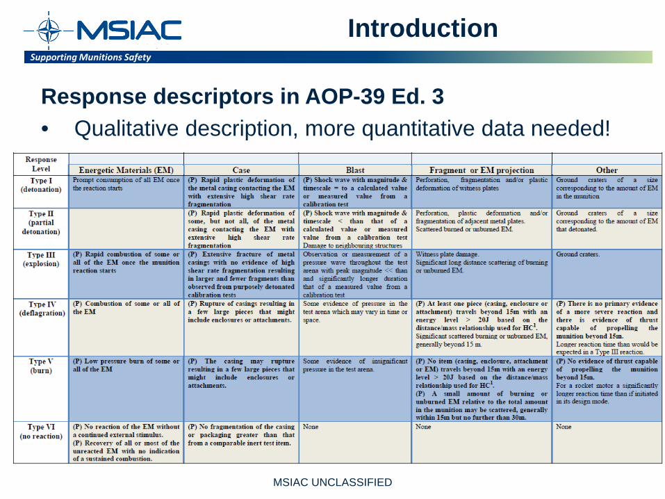
Response descriptors in AOP-39 Ed. 3 • Qualitative description, more quantitative data needed!
MSIAC UNCLASSIFIED
Supporting Munitions Safety Supporting Munitions Safety
Introduction
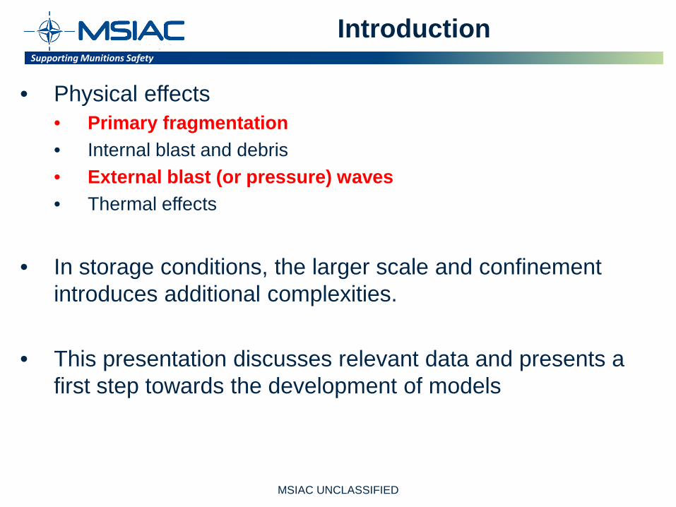
• Physical effects • Primary fragmentation • Internal blast and debris • External blast (or pressure) waves • Thermal effects
• In storage conditions, the larger scale and confinement introduces additional complexities.
• This presentation discusses relevant data and presents a first step towards the development of models
MSIAC UNCLASSIFIED
Supporting Munitions Safety Supporting Munitions Safety
Primary fragmentation
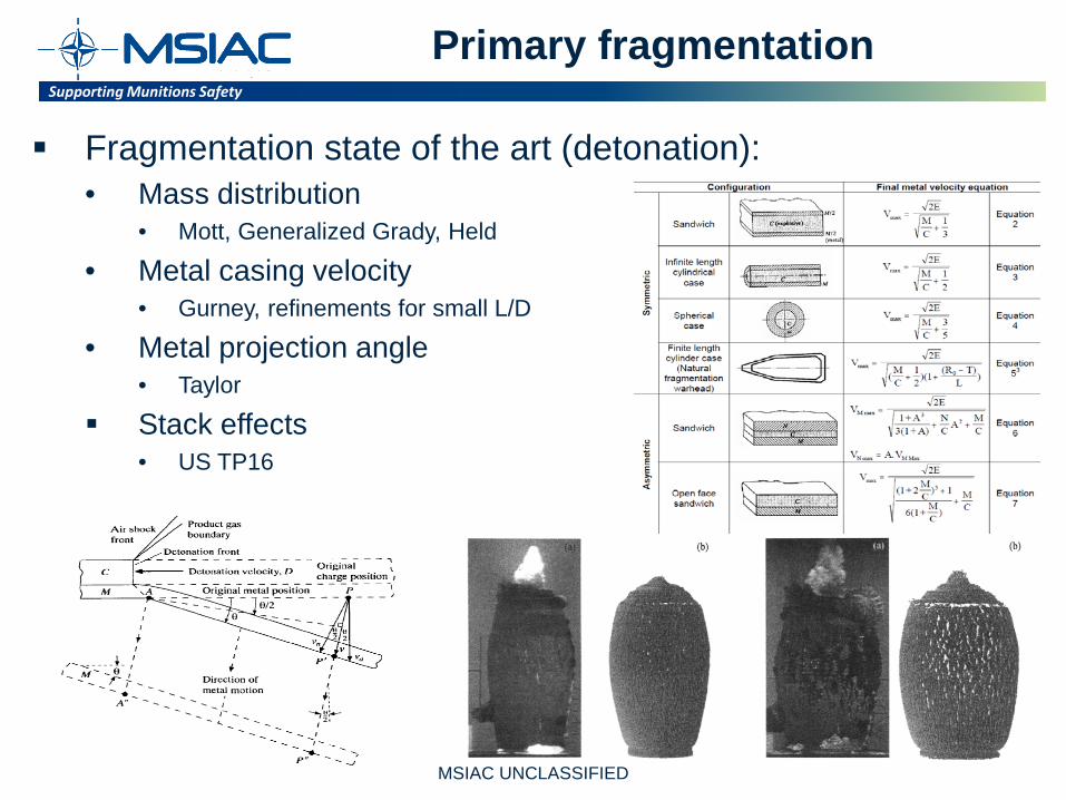
Fragmentation state of the art (detonation): • Mass distribution
• Mott, Generalized Grady, Held
• Metal casing velocity • Gurney, refinements for small L/D
• Metal projection angle • Taylor
Stack effects • US TP16
MSIAC UNCLASSIFIED
Supporting Munitions Safety Supporting Munitions Safety
Primary fragmentation
Fragmentation process depends on: • Explosive reaction rate • Warhead burst volume • Fragment explosive contact surface area
Detonative regime • Fragmentation starts after expansion to two times original volume • Lasts until three times the original volume
Sub-detonative regime • Lower reaction rate • Case wall breaks before reaction completed • Lower velocity, fewer number of cracks, fewer but larger fragments • Plate- or strip-like shape, thinning of fragments due to case expansion
MSIAC UNCLASSIFIED
Supporting Munitions Safety Supporting Munitions Safety
Primary fragmentation
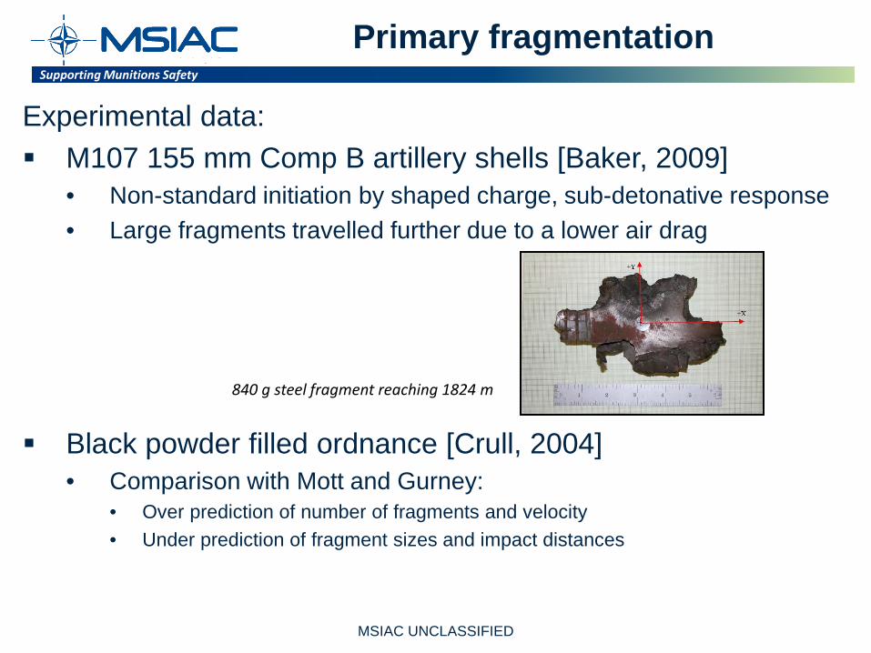
Experimental data: M107 155 mm Comp B artillery shells [Baker, 2009]
• Non-standard initiation by shaped charge, sub-detonative response • Large fragments travelled further due to a lower air drag
Black powder filled ordnance [Crull, 2004] • Comparison with Mott and Gurney:
• Over prediction of number of fragments and velocity • Under prediction of fragment sizes and impact distances
840 g steel fragment reaching 1824 m
MSIAC UNCLASSIFIED

Supporting Munitions Safety Supporting Munitions Safety
Primary fragmentation
Experimental data: Tests with deflagrating munitions [Kinsey, 1992] and [Chick, 1992]
• Quantification of the large strip-like fragments • Fragment velocities are much slower (between 10 and 33% of same
detonated munition) Tests with tritonal Mk82 bombs [Vercruyssen, 2014]
• Inspection of 6 MK82 bombs • Formation yellow crystals (TNT) in 3 cases • These shells give partial detonation and large strip-like fragments
MSIAC UNCLASSIFIED

Supporting Munitions Safety Supporting Munitions Safety
Primary fragmentation
Dial a yield technology [Arnold, 2011] Selection of a desired munitions response between
deflagration and detonation (different initiation strengths) A proof of concept was developed and experiments showed
that blast and fragmentation effects could be tuned between low and high output.
MSIAC UNCLASSIFIED

Supporting Munitions Safety Supporting Munitions Safety
Primary fragmentation
Modelling of fragment characteristics for sub-detonative response Three dimensional high rate continuum modeling [Baker, 2009]
Successful reproduction of fragment size and shape Distance of 1824 m possible due to spin stabilized edge-on orientation Caused by “hinge”
MSIAC UNCLASSIFIED

Supporting Munitions Safety Supporting Munitions Safety
Primary fragmentation
Trajectory analysis with TRAJCAN* Fragments modelled as tumbling rectangular steel plates Strong dependency on plate thickness
0
200
400
600
800
1000
1200
1400
1600
1800
-90 -75 -60 -45 -30 -15 0 15 30 45 60 75 90
Impa
ct d
ista
nce
(m)
Launch angle (deg)
Tumbling 10mm steel plate launched from 1 m height
250 m/s
500 m/s
750 m/s
1000 m/s
1250 m/s
1500 m/s
0
200
400
600
800
1000
1200
1400
1600
1800
-90 -75 -60 -45 -30 -15 0 15 30 45 60 75 90
Impa
ct d
ista
nce
(m)
Launch angle (deg)
Tumbling 30mm steel plate launched from 1 m height
250 m/s
500 m/s
750 m/s
1000 m/s
1250 m/s
1500 m/s
*TRAJCAN was developed by ACTA [Chrostowski, 2014] MSIAC UNCLASSIFIED
Supporting Munitions Safety Supporting Munitions Safety
Primary fragmentation
A few large fragments that reach large distances! • Maximum Fragment Distance (MFD) is very large • Hit probability and Hazardous Fragment Distance (HFD)
may be very small
What is an appropriate methodology to determine safety distances? • MFD, HFD or another approach?
MSIAC UNCLASSIFIED
Supporting Munitions Safety Supporting Munitions Safety
Conclusions (fragments)
Reduced reaction rate leads to: • Larger strip-like fragments • Smaller velocity
Modelling of fragment characteristics Possible with 3D high rate continuum modelling Engineering models are still missing
Modelling of fragment trajectories Possible with correct assumption about orientation “Edge-on” or “Tumbling”
Safety Distances What is an appropriate definition, MFD, HFD, other?
MSIAC UNCLASSIFIED
Supporting Munitions Safety Supporting Munitions Safety
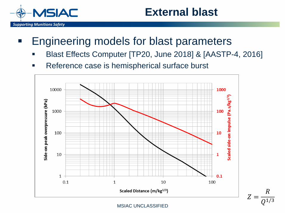
External blast
Engineering models for blast parameters Blast Effects Computer [TP20, June 2018] & [AASTP-4, 2016] Reference case is hemispherical surface burst
𝑍𝑍 =𝑅𝑅
𝑄𝑄1/3 MSIAC UNCLASSIFIED
Supporting Munitions Safety Supporting Munitions Safety
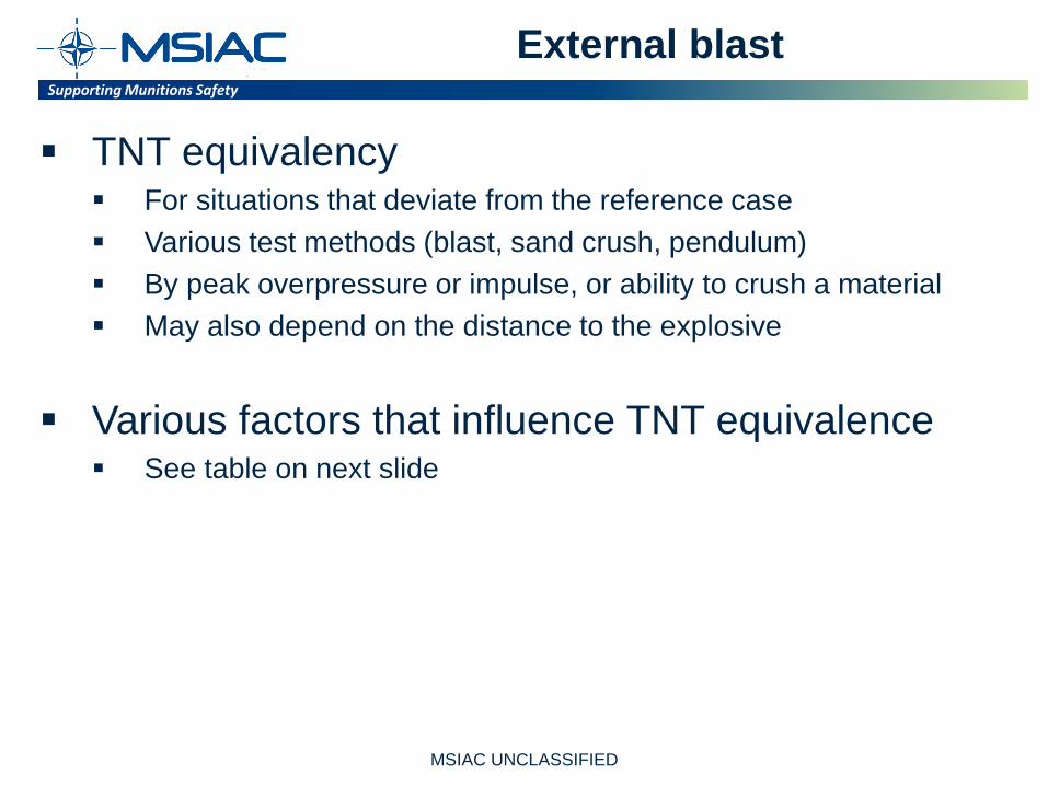
External blast
TNT equivalency For situations that deviate from the reference case Various test methods (blast, sand crush, pendulum) By peak overpressure or impulse, or ability to crush a material May also depend on the distance to the explosive
Various factors that influence TNT equivalence See table on next slide
MSIAC UNCLASSIFIED

Supporting Munitions Safety Supporting Munitions Safety
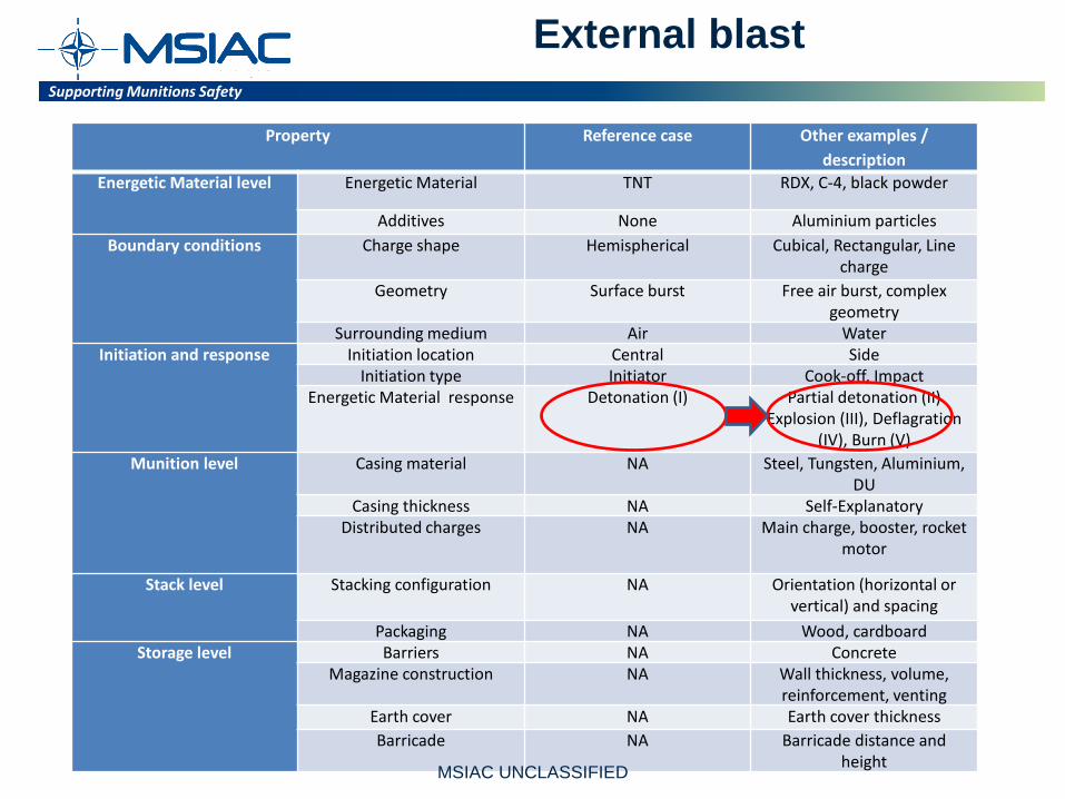
Property Reference case Other examples / description
Energetic Material level Energetic Material TNT RDX, C-4, black powder
Additives None Aluminium particles Boundary conditions Charge shape Hemispherical Cubical, Rectangular, Line
charge Geometry Surface burst Free air burst, complex
geometry Surrounding medium Air Water
Initiation and response Initiation location Central Side Initiation type Initiator Cook-off, Impact
Energetic Material response Detonation (I) Partial detonation (II) Explosion (III), Deflagration
(IV), Burn (V) Munition level Casing material NA Steel, Tungsten, Aluminium,
DU Casing thickness NA Self-Explanatory
Distributed charges NA Main charge, booster, rocket motor
Stack level Stacking configuration NA Orientation (horizontal or vertical) and spacing
Packaging NA Wood, cardboard Storage level Barriers NA Concrete
Magazine construction NA Wall thickness, volume, reinforcement, venting
Earth cover NA Earth cover thickness Barricade NA Barricade distance and
height
External blast
MSIAC UNCLASSIFIED
Supporting Munitions Safety Supporting Munitions Safety
External blast
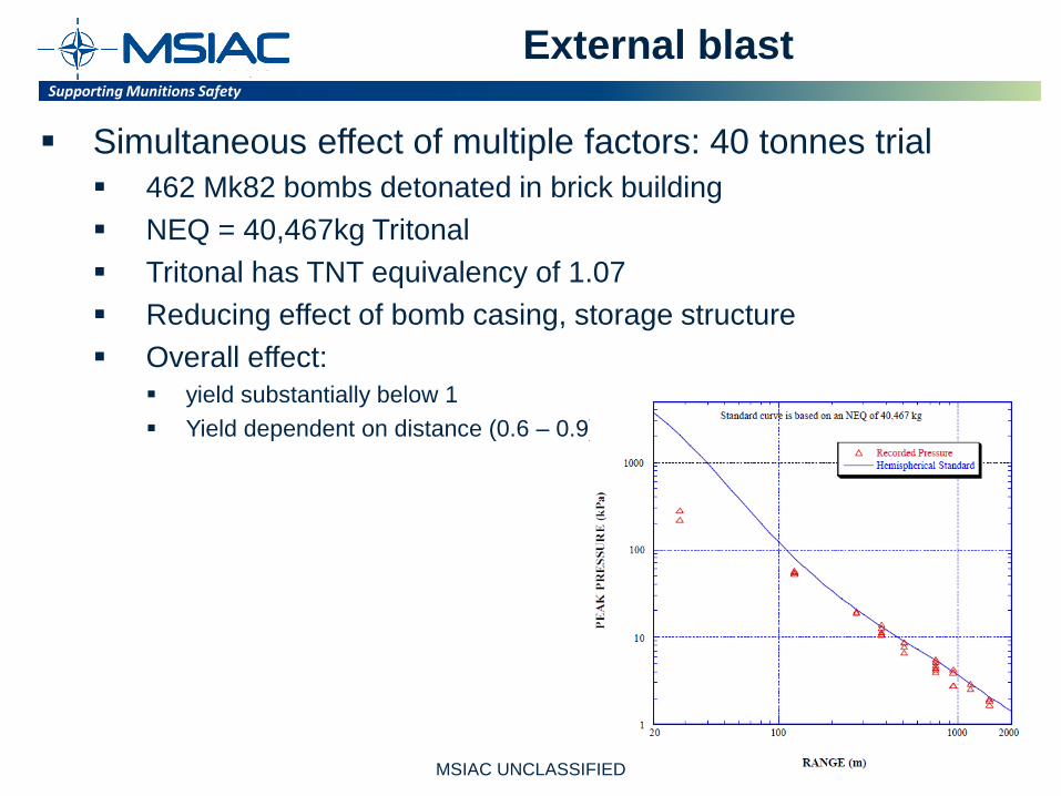
Simultaneous effect of multiple factors: 40 tonnes trial 462 Mk82 bombs detonated in brick building NEQ = 40,467kg Tritonal Tritonal has TNT equivalency of 1.07 Reducing effect of bomb casing, storage structure Overall effect:
yield substantially below 1 Yield dependent on distance (0.6 – 0.9)
MSIAC UNCLASSIFIED
Supporting Munitions Safety Supporting Munitions Safety
Property Reference case Other examples / description
Energetic Material level Energetic Material TNT RDX, C-4, black powder
Additives None Aluminium particles Boundary conditions Charge shape Hemispherical Cubical, Rectangular, Line
charge Geometry Surface burst Free air burst, complex
geometry Surrounding medium Air Water
Initiation and response Initiation location Central Side Initiation type Initiator Cook-off, Impact
Energetic Material response Detonation (I) Partial detonation (II) Explosion (III), Deflagration
(IV), Burn (V) Munition level Casing material NA Steel, Tungsten, Aluminium,
DU Casing thickness NA Self-Explanatory
Distributed charges NA Main charge, booster, rocket motor
Stack level Stacking configuration NA Orientation (horizontal or vertical) and spacing
Packaging NA Wood, cardboard Storage level Barriers NA Concrete
Magazine construction NA Wall thickness, volume, reinforcement, venting
Earth cover NA Earth cover thickness Barricade NA Barricade distance and
height
External blast
MSIAC UNCLASSIFIED

Supporting Munitions Safety Supporting Munitions Safety
External blast
What if response type is not a (full) detonation? Most appropriate: model that accounts for lower reaction
rate and lower explosion overpressures Multi-Energy (ME) method [Van den Berg, 2006]. Developed for gas explosions Based on numerical simulation of a flame propagating at
different speeds through hydrocarbon-air mixture Model distinguishes between 10 different explosion
overpressures Charts for peak overpressure, impulse, positive phase duration,
dynamic pressure
MSIAC UNCLASSIFIED
Supporting Munitions Safety Supporting Munitions Safety
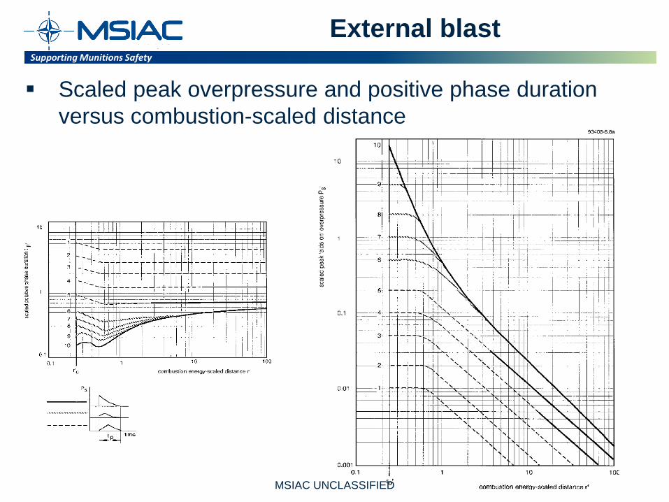
External blast
Scaled peak overpressure and positive phase duration versus combustion-scaled distance
MSIAC UNCLASSIFIED

Supporting Munitions Safety Supporting Munitions Safety
IBD curve 6 - 10IBD curve 3 - 5
External blast
Comparison with: TNT blast (red)
• Good match
Pyrotechnic mixture (MTV) used in flares • 1.5 kg (green) • 12 kg (blue) • Curves not parallel • Better match with lower ME curves
(e.g. 6 – 8)
5 kPa IBD level (purple) Same distance for curve 6 – 8 Reduction for curve 3 - 5 Zero for curve 1 & 2
MSIAC UNCLASSIFIED

Supporting Munitions Safety Supporting Munitions Safety
Conclusion (External blast)
External blast will reduce in strength, representation by: • TNT equivalency • Models that account for a lower reaction rate and
lower explosion overpressures
• The potential of the Multi-Energy method (originally developed for gas-explosions) has been investigated
MSIAC UNCLASSIFIED

Supporting Munitions Safety Supporting Munitions Safety
Recommendations
Extension of standardized IM tests with a more detailed measurement of fragmentation and blast for the purpose of model validation
Specification of more quantitative measures to help define the munition response in terms of reaction rate
Focus on full scale testing of IM
MSIAC UNCLASSIFIED
Supporting Munitions Safety Supporting Munitions Safety
Recommendations
• CFD and engineering models could focus more on fragmentation, internal and external blast for limited reactions rates.
• We hope that the findings in this paper will aid the development of Quantity Distances (QD) and risk management of future munitions for a range of responses
MSIAC UNCLASSIFIED
Supporting Munitions Safety Supporting Munitions Safety
25
Questions?