physical guides: an analysis of 3d sketching performance ... · gravity sketch vr2 focus on...
TRANSCRIPT
Physical Guides: An Analysis of 3DSketching Performance on PhysicalObjects in Augmented Reality
Philipp WackerRWTH Aachen University52056 Aachen, [email protected]
Adrian WagnerRWTH Aachen University52056 Aachen, [email protected]
Simon VoelkerRWTH Aachen University52056 Aachen, [email protected]
Jan BorchersRWTH Aachen University52056 Aachen, [email protected]
Permission to make digital or hard copies of part or all of this work for personal orclassroom use is granted without fee provided that copies are not made or distributedfor profit or commercial advantage and that copies bear this notice and the full citationon the first page. Copyrights for third-party components of this work must be honored.For all other uses, contact the owner/author(s).
Copyright held by the owner/author(s).CHI’18 Extended Abstracts, April 21–26, 2018, Montreal, QC, CanadaACM 978-1-4503-5621-3/18/04.https://doi.org/10.1145/3170427.3188493
AbstractAugmented Reality (AR) lets users sketch 3D designs di-rectly attached to existing physical objects. These objectsprovide natural haptic feedback whenever the pen touchesthem, and, unlike in VR, there is no need to digitize thephysical object first. Especially in Personal Fabrication, thislets non-professional designers quickly create simple 3Dmodels that fit existing physical objects. We studied how ac-curately visual lines and concave/convex surfaces let usersdraw 3D shapes attached to physical vs. virtual objects inAR. Results show that tracing physical objects is 48% moreaccurate, but takes longer than tracing virtual objects. Con-cave physical edges further improve accuracy due to theirhaptic guidance. Our findings provide initial metrics whendesigning AR sketching systems.
Author KeywordsAugmented reality; 3D sketching; tracing; motor ability;physical objects; guide classification.
ACM Classification KeywordsH.5.1. [Multimedia Information Systems]: Artificial, aug-mented, and virtual realities
IntroductionThe recent advancement of Virtual Reality (VR) and Aug-mented Reality (AR) technology has rekindled an interest
in using these techniques in 3D design tasks. Numerousresearch projects [2, 5, 7] and products like Tiltbrush1 orGravity Sketch VR2 focus on sketching in mid-air to createand view 3D models in both VR and AR.
However, only AR enables sketching directly on existingphysical objects in the real world, whether to extend them orto design a new, matching object. This is particularly helpfulwhen designing an object that has to fit an existing object,such as a snap-on handle for a drinks container. Being ableto achieve this quickly and easily without extensive knowl-edge of professional modeling tools opens up 3D object de-sign to novices. In VR, the user would first need to digitizethe existing model. In AR, she can use the physical objectdirectly instead. This also adds the benefit of haptic feed-back from the physical object surfaces as guidance duringthe modeling task.
Condition Significance Mean SD
Physical A 4.93 1.98Virtual B 9.48 4.70Convex A 6.70 4.07Visual A 6.91 3.97Concave A 7.16 4.69No Guide B 8.09 4.18Physical, Concave A 4.11 1.52Physical, Visual B 4.74 1.44Physical, Convex B 4.97 1.79Physical, No Guide C 5.90 2.54Virtual, Convex D 8.48 4.90Virtual, Visual D 9.00 4.48Virtual, Concave E 10.13 4.83Virtual, No Guide E 10.25 4.35
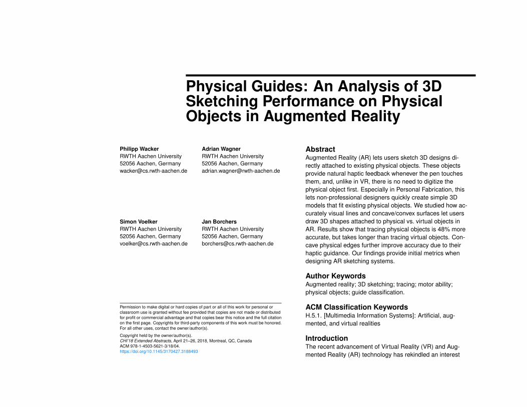
Constraint Virtual Physical
No Guide Virtual table surface
Real table surface
Visual Pen stroke on a virtual sketch
Waterline in a bottle
Concave Inside of a virtual bucket
Intersection of shelf & wall
Convex Edge of a virtual desk
Opening of a wine glass
�1
Figure 1: Examples for allcombinations of initial constraint &subsequent limitation to a line.
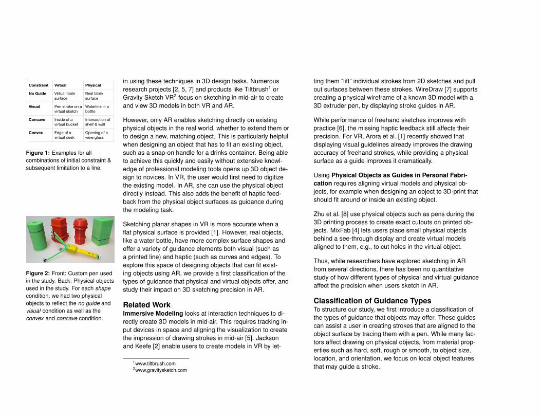
Figure 2: Front: Custom pen usedin the study. Back: Physical objectsused in the study. For each shapecondition, we had two physicalobjects to reflect the no guide andvisual condition as well as theconvex and concave condition.
Sketching planar shapes in VR is more accurate when aflat physical surface is provided [1]. However, real objects,like a water bottle, have more complex surface shapes andoffer a variety of guidance elements both visual (such asa printed line) and haptic (such as curves and edges). Toexplore this space of designing objects that can fit exist-ing objects using AR, we provide a first classification of thetypes of guidance that physical and virtual objects offer, andstudy their impact on 3D sketching precision in AR.
Related WorkImmersive Modeling looks at interaction techniques to di-rectly create 3D models in mid-air. This requires tracking in-put devices in space and aligning the visualization to createthe impression of drawing strokes in mid-air [5]. Jacksonand Keefe [2] enable users to create models in VR by let-
1www.tiltbrush.com2www.gravitysketch.com
ting them “lift” individual strokes from 2D sketches and pullout surfaces between these strokes. WireDraw [7] supportscreating a physical wireframe of a known 3D model with a3D extruder pen, by displaying stroke guides in AR.
While performance of freehand sketches improves withpractice [6], the missing haptic feedback still affects theirprecision. For VR, Arora et al. [1] recently showed thatdisplaying visual guidelines already improves the drawingaccuracy of freehand strokes, while providing a physicalsurface as a guide improves it dramatically.
Using Physical Objects as Guides in Personal Fabri-cation requires aligning virtual models and physical ob-jects, for example when designing an object to 3D-print thatshould fit around or inside an existing object.
Zhu et al. [8] use physical objects such as pens during the3D printing process to create exact cutouts on printed ob-jects. MixFab [4] lets users place small physical objectsbehind a see-through display and create virtual modelsaligned to them, e.g., to cut holes in the virtual object.
Thus, while researchers have explored sketching in ARfrom several directions, there has been no quantitativestudy of how different types of physical and virtual guidanceaffect the precision when users sketch in AR.
Classification of Guidance TypesTo structure our study, we first introduce a classification ofthe types of guidance that objects may offer. These guidescan assist a user in creating strokes that are aligned to theobject surface by tracing them with a pen. While many fac-tors affect drawing on physical objects, from material prop-erties such as hard, soft, rough or smooth, to object size,location, and orientation, we focus on local object featuresthat may guide a stroke.
The guidance types on an object can be seen as limitingthe degrees of freedom for sketching. The first limitationguides the free-hand movement to a surface by constrain-ing one degree of freedom (surface guidance). On physicalobjects, this constraint is hard for one half degree of free-dom (can’t push inside the object) and soft for the other half(can lift pen off surface). On virtual objects, it is entirely asoft constraint. Movement can be limited further to tracinga 1D line or curve by visual guides and object shape (lineguidance). Curvature increases guidance, with concaveand convex edges as extremes. Concave shapes providemore guidance, reducing the degree of freedom more thanconvex shapes. This results in 8 combinations (Fig. 1).
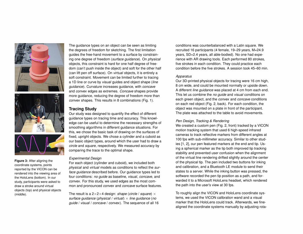
Figure 3: After aligning thecoordinate systems, pointsreported by the VICON can berendered into the viewing area ofthe HoloLens (bottom). In ourstudy, participants were asked todraw a stroke around virtualobjects (top) and physical objects(middle).
Tracing StudyOur study was designed to quantify the effect of differentguidance types on tracing time and accuracy. This knowl-edge can be useful to determine the necessary strengths ofsmoothing algorithms in different guidance situations. Forthis, we chose the basic task of drawing on the surfaces offixed, upright objects. We chose a cylinder and a cuboid asour basic object types, around which the user had to draw acircle and square, respectively. We measured accuracy bycomparing the trace to the optimal shape.
Experimental DesignFor each object (cylinder and cuboid), we included bothphysical and virtual models as conditions to reflect the sur-face guidance described before. Our guidance types led tofour conditions: no guide as baseline, visual , concave, andconvex . For this study, we used edges as the most com-mon and pronounced convex and concave surface features.
The result is a 2×2×4 design: shape (circle / square) ×surface guidance (physical / virtual) × line guidance (noguide / visual / concave / convex). The sequence of all 16
conditions was counterbalanced with a Latin square. Werecruited 16 participants (4 female, 19–29 years, M=24.9years, SD=2.4 years, all able-bodied). No one had expe-rience with AR drawing tools. Each performed 80 strokes,five strokes in each condition. They could practice eachcondition before the five strokes. A session took 45–60 min.
ApparatusOur 3D-printed physical objects for tracing were 16 cm high,8 cm wide, and could be mounted normally or upside down.A different line guidance was placed at 4 cm from each end.This let us combine the no guide and visual conditions oneach green object, and the convex and concave conditionson each red object (Fig. 2, back). For each condition, theobject was mounted on a plate in front of the participant.The plate was attached to the table to avoid movements.
Pen Design, Tracking & RenderingWe created a custom pen (Fig. 2, front) tracked by a VICONmotion tracking system that used 6 high-speed infraredcameras to track reflective markers from different angles at100 fps with sub-millimeter accuracy. Similar to other stud-ies [1, 2], our pen featured markers at the end and tip. Us-ing a spherical marker as the tip both improved tip trackingstability and prevented user confusion when the alignmentof the virtual line rendering drifted slightly around the centerof the physical tip. The pen included two buttons for inkingand calibration, and a Bluetooth LE module to send theirstates to a server. While the inking button was pressed, thesoftware recorded the pen tip position as a path, and for-warded it to a Microsoft HoloLens headset, which renderedthe path into the user’s view at 30 fps.
To roughly align the VICON and HoloLens coordinate sys-tems, we used the VICON calibration wand and a visualmarker that the HoloLens could track. Afterwards, we fine-aligned the coordinate systems manually by adjusting rota-
tion and location of a digital model to fit a real-world coun-terpart placed at a known point.
Based on pilot tests, we occluded those parts of the pathbehind the model in both the physical and the virtual condi-tion to preserve realism (Fig. 3, top).
Condition Significance Mean SDPhysical A 4.93 1.98Virtual B 9.48 4.70Convex A 6.70 4.07Visual A 6.91 3.97Concave A 7.16 4.69No Guide B 8.09 4.18Physical, Concave
A 4.11 1.52Physical, Visual B 4.74 1.44Physical, Convex B 4.97 1.79Physical, No Guide
C 5.90 2.54Virtual, Convex D 8.48 4.90Virtual, Visual D 9.00 4.48Virtual, Concave E 10.13 4.83Virtual, No Guide E 10.25 4.35
Constraint Virtual Physical
No Guide Virtual table surface
Real table surface
Visual Pen stroke on a virtual sketch
Waterline in a bottle
Concave Inside of a virtual bucket
Intersection of shelf & wall
Convex Edge of a virtual desk
Opening of a wine glass
�1
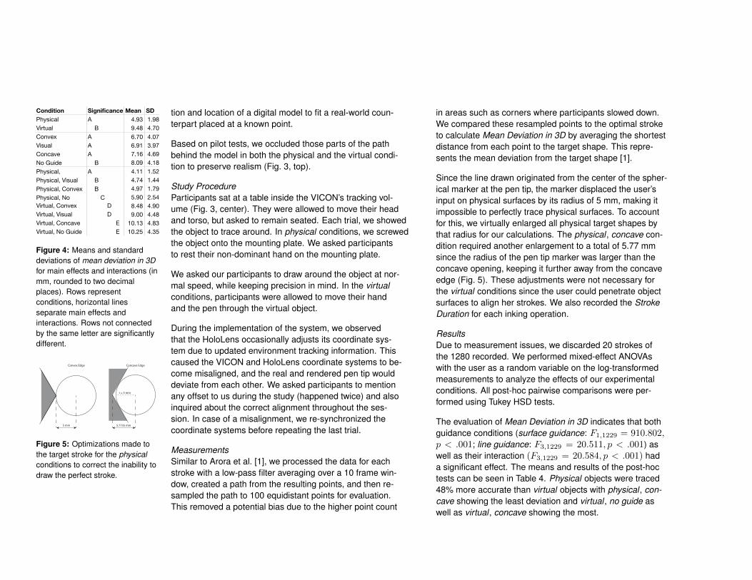
Figure 4: Means and standarddeviations of mean deviation in 3Dfor main effects and interactions (inmm, rounded to two decimalplaces). Rows representconditions, horizontal linesseparate main effects andinteractions. Rows not connectedby the same letter are significantlydifferent.
r = 5 mm
5.7735 mm
Concave Edge
5 mm
Convex Edge
Figure 5: Optimizations made tothe target stroke for the physicalconditions to correct the inability todraw the perfect stroke.
Study ProcedureParticipants sat at a table inside the VICON’s tracking vol-ume (Fig. 3, center). They were allowed to move their headand torso, but asked to remain seated. Each trial, we showedthe object to trace around. In physical conditions, we screwedthe object onto the mounting plate. We asked participantsto rest their non-dominant hand on the mounting plate.
We asked our participants to draw around the object at nor-mal speed, while keeping precision in mind. In the virtualconditions, participants were allowed to move their handand the pen through the virtual object.
During the implementation of the system, we observedthat the HoloLens occasionally adjusts its coordinate sys-tem due to updated environment tracking information. Thiscaused the VICON and HoloLens coordinate systems to be-come misaligned, and the real and rendered pen tip woulddeviate from each other. We asked participants to mentionany offset to us during the study (happened twice) and alsoinquired about the correct alignment throughout the ses-sion. In case of a misalignment, we re-synchronized thecoordinate systems before repeating the last trial.
MeasurementsSimilar to Arora et al. [1], we processed the data for eachstroke with a low-pass filter averaging over a 10 frame win-dow, created a path from the resulting points, and then re-sampled the path to 100 equidistant points for evaluation.This removed a potential bias due to the higher point count
in areas such as corners where participants slowed down.We compared these resampled points to the optimal stroketo calculate Mean Deviation in 3D by averaging the shortestdistance from each point to the target shape. This repre-sents the mean deviation from the target shape [1].
Since the line drawn originated from the center of the spher-ical marker at the pen tip, the marker displaced the user’sinput on physical surfaces by its radius of 5 mm, making itimpossible to perfectly trace physical surfaces. To accountfor this, we virtually enlarged all physical target shapes bythat radius for our calculations. The physical , concave con-dition required another enlargement to a total of 5.77 mmsince the radius of the pen tip marker was larger than theconcave opening, keeping it further away from the concaveedge (Fig. 5). These adjustments were not necessary forthe virtual conditions since the user could penetrate objectsurfaces to align her strokes. We also recorded the StrokeDuration for each inking operation.
ResultsDue to measurement issues, we discarded 20 strokes ofthe 1280 recorded. We performed mixed-effect ANOVAswith the user as a random variable on the log-transformedmeasurements to analyze the effects of our experimentalconditions. All post-hoc pairwise comparisons were per-formed using Tukey HSD tests.
The evaluation of Mean Deviation in 3D indicates that bothguidance conditions (surface guidance: F1,1229 = 910.802,p < .001; line guidance: F3,1229 = 20.511, p < .001) aswell as their interaction (F3,1229 = 20.584, p < .001) hada significant effect. The means and results of the post-hoctests can be seen in Table 4. Physical objects were traced48% more accurate than virtual objects with physical , con-cave showing the least deviation and virtual , no guide aswell as virtual , concave showing the most.
For the Stroke Duration we report two interesting findings.Participants took longer to draw around a physical (M =9.05s, SD = 4.97) compared to a virtual object (M = 8.8s,SD = 6.13) (F1,1229 = 11.253, p < .001). The physical ,concave object (M = 7.96s, SD = 3.73) had the lowestaverage duration and was significantly faster compared tothe physical , convex object which was the slowest (M =10.08s, SD = 5.78).
No Guide
PhysicalVirtual
Convex
ConcaveVisual
PhysicalVirtual
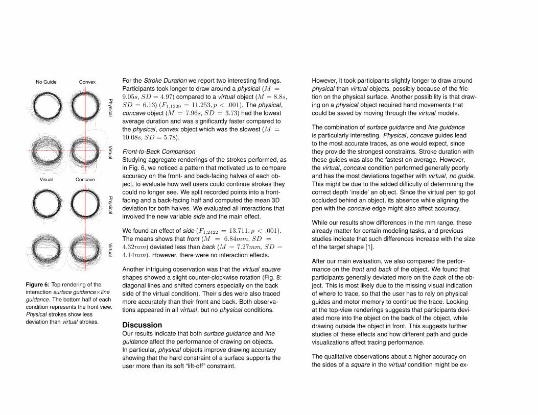
Figure 6: Top rendering of theinteraction surface guidance×lineguidance. The bottom half of eachcondition represents the front view.Physical strokes show lessdeviation than virtual strokes.
Front-to-Back ComparisonStudying aggregate renderings of the strokes performed, asin Fig. 6, we noticed a pattern that motivated us to compareaccuracy on the front- and back-facing halves of each ob-ject, to evaluate how well users could continue strokes theycould no longer see. We split recorded points into a front-facing and a back-facing half and computed the mean 3Ddeviation for both halves. We evaluated all interactions thatinvolved the new variable side and the main effect.
We found an effect of side (F1,2422 = 13.711, p < .001).The means shows that front (M = 6.84mm, SD =4.32mm) deviated less than back (M = 7.27mm, SD =4.14mm). However, there were no interaction effects.
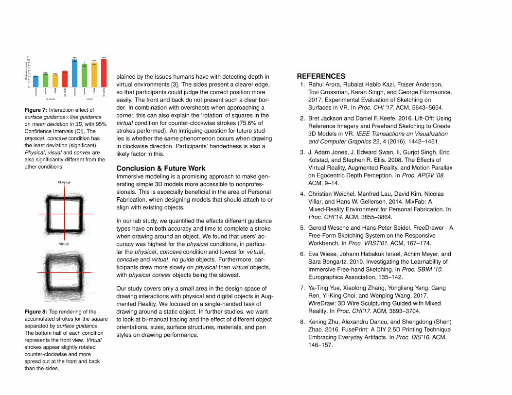
Another intriguing observation was that the virtual squareshapes showed a slight counter-clockwise rotation (Fig. 8:diagonal lines and shifted corners especially on the backside of the virtual condition). Their sides were also tracedmore accurately than their front and back. Both observa-tions appeared in all virtual , but no physical conditions.
DiscussionOur results indicate that both surface guidance and lineguidance affect the performance of drawing on objects.In particular, physical objects improve drawing accuracyshowing that the hard constraint of a surface supports theuser more than its soft “lift-off” constraint.
However, it took participants slightly longer to draw aroundphysical than virtual objects, possibly because of the fric-tion on the physical surface. Another possibility is that draw-ing on a physical object required hand movements thatcould be saved by moving through the virtual models.
The combination of surface guidance and line guidanceis particularly interesting. Physical , concave guides leadto the most accurate traces, as one would expect, sincethey provide the strongest constraints. Stroke duration withthese guides was also the fastest on average. However,the virtual , concave condition performed generally poorlyand has the most deviations together with virtual , no guide.This might be due to the added difficulty of determining thecorrect depth ‘inside’ an object. Since the virtual pen tip gotoccluded behind an object, its absence while aligning thepen with the concave edge might also affect accuracy.
While our results show differences in the mm range, thesealready matter for certain modeling tasks, and previousstudies indicate that such differences increase with the sizeof the target shape [1].
After our main evaluation, we also compared the perfor-mance on the front and back of the object. We found thatparticipants generally deviated more on the back of the ob-ject. This is most likely due to the missing visual indicationof where to trace, so that the user has to rely on physicalguides and motor memory to continue the trace. Lookingat the top-view renderings suggests that participants devi-ated more into the object on the back of the object, whiledrawing outside the object in front. This suggests furtherstudies of these effects and how different path and guidevisualizations affect tracing performance.
The qualitative observations about a higher accuracy onthe sides of a square in the virtual condition might be ex-
plained by the issues humans have with detecting depth invirtual environments [3]. The sides present a clearer edge,so that participants could judge the correct position moreeasily. The front and back do not present such a clear bor-der. In combination with overshoots when approaching acorner, this can also explain the ‘rotation’ of squares in thevirtual condition for counter-clockwise strokes (75.6% ofstrokes performed). An intriguing question for future stud-ies is whether the same phenomenon occurs when drawingin clockwise direction. Participants’ handedness is also alikely factor in this.
3D d
evia
tion
(mm
)
0123456789
1011
conc
ave
conv
ex
visu
al
no g
uide
conc
ave
conv
ex
visu
al
no g
uide
physical virtual
Figure 7: Interaction effect ofsurface guidance×line guidanceon mean deviation in 3D, with 95%Confidence Intervals (CI). Thephysical , concave condition hasthe least deviation (significant).Physical , visual and convex arealso significantly different from theother conditions.
Virtual
Physical
Figure 8: Top rendering of theaccumulated strokes for the squareseparated by surface guidance.The bottom half of each conditionrepresents the front view. Virtualstrokes appear slightly rotatedcounter-clockwise and morespread out at the front and backthan the sides.
Conclusion & Future WorkImmersive modeling is a promising approach to make gen-erating simple 3D models more accessible to nonprofes-sionals. This is especially beneficial in the area of PersonalFabrication, when designing models that should attach to oralign with existing objects.
In our lab study, we quantified the effects different guidancetypes have on both accuracy and time to complete a strokewhen drawing around an object. We found that users’ ac-curacy was highest for the physical conditions, in particu-lar the physical , concave condition and lowest for virtual ,concave and virtual , no guide objects. Furthermore, par-ticipants drew more slowly on physical than virtual objects,with physical convex objects being the slowest.
Our study covers only a small area in the design space ofdrawing interactions with physical and digital objects in Aug-mented Reality. We focused on a single-handed task ofdrawing around a static object. In further studies, we wantto look at bi-manual tracing and the effect of different objectorientations, sizes, surface structures, materials, and penstyles on drawing performance.
REFERENCES1. Rahul Arora, Rubaiat Habib Kazi, Fraser Anderson,
Tovi Grossman, Karan Singh, and George Fitzmaurice.2017. Experimental Evaluation of Sketching onSurfaces in VR. In Proc. CHI '17. ACM, 5643–5654.
2. Bret Jackson and Daniel F. Keefe. 2016. Lift-Off: UsingReference Imagery and Freehand Sketching to Create3D Models in VR. IEEE Transactions on Visualizationand Computer Graphics 22, 4 (2016), 1442–1451.
3. J. Adam Jones, J. Edward Swan, II, Gurjot Singh, EricKolstad, and Stephen R. Ellis. 2008. The Effects ofVirtual Reality, Augmented Reality, and Motion Parallaxon Egocentric Depth Perception. In Proc. APGV ’08.ACM, 9–14.
4. Christian Weichel, Manfred Lau, David Kim, NicolasVillar, and Hans W. Gellersen. 2014. MixFab: AMixed-Reality Environment for Personal Fabrication. InProc. CHI'14. ACM, 3855–3864.
5. Gerold Wesche and Hans-Peter Seidel. FreeDrawer - AFree-Form Sketching System on the ResponsiveWorkbench. In Proc. VRST'01. ACM, 167–174.
6. Eva Wiese, Johann Habakuk Israel, Achim Meyer, andSara Bongartz. 2010. Investigating the Learnability ofImmersive Free-hand Sketching. In Proc. SBIM ’10.Eurographics Association, 135–142.
7. Ya-Ting Yue, Xiaolong Zhang, Yongliang Yang, GangRen, Yi-King Choi, and Wenping Wang. 2017.WireDraw: 3D Wire Sculpturing Guided with MixedReality. In Proc. CHI'17. ACM, 3693–3704.
8. Kening Zhu, Alexandru Dancu, and Shengdong (Shen)Zhao. 2016. FusePrint: A DIY 2.5D Printing TechniqueEmbracing Everyday Artifacts. In Proc. DIS'16. ACM,146–157.