physical models for moving shadow and object detection in … and conference papers... · physical...
TRANSCRIPT

Physical Models for Moving Shadow andObject Detection in Video
Sohail Nadimi, Member, IEEE, andBir Bhanu, Fellow, IEEE
Abstract—Current moving object detection systems typically detect shadows cast
by the moving object as part of the moving object. In this paper, the problem of
separating moving cast shadows from the moving objects in an outdoor
environment is addressed. Unlike previous work, we present an approach that
does not rely on any geometrical assumptions such as camera location and
ground surface/object geometry. The approach is based on a new spatio-temporal
albedo test and dichromatic reflection model and accounts for both the sun and the
sky illuminations. Results are presented for several video sequences representing
a variety of ground materials when the shadows are cast on different surface
types. These results show that our approach is robust to widely different
background and foreground materials, and illuminations.
Index Terms—Detecting moving objects, dichromatic reflection model, physics-
based segmentation, shadows in video, spatio-temporal albedo ratio.
�
1 INTRODUCTION
OVER the past several decades, many approaches have beendeveloped for detecting moving objects in indoor and outdoorscenes. Recently, statistical-based approaches using a mixturemodel have shown that many problematic phenomena such asrepetitive motion of the background (e.g., swaying trees), suddenillumination changes (e.g., cloud cover), and sensor noise can bemodeled [4], [8], [16]. Despite this success, a statistical-basedapproach fails to distinguish between the actual moving object andits shadow silhouette. This is due to the fact that intensity changesin the scene due to moving shadows are as high as those of the newobjects appearing in a scene.
Shadows are generally divided into static and dynamicshadows. Static shadows are shadows due to static objects suchas buildings, parked cars, trees, etc. Statistical-based methods formoving object detection in video do not suffer from static shadowssince static shadows are modeled as part of the background andcan be tracked by an adaptive procedure. Dynamic shadows invideo, the subject of interest in this paper, are due to movingobjects such as moving vehicles (cars, trucks), pedestrians, etc. Theshadows can take on any size and shape, and can be Umbra (darkshadow), Penumbra (soft shadow), or both. Our research focuses onoutdoor scenes where we have a far away point source (sun) and adiffuse source (sky) contributing to the illumination in the scene.Since the distance between the objects and the background isnegligible compared to the distance of illumination sources to theobjects, most or all of the shadows are umbra or strong shadowthat we deal with in this paper. Note that penumbra or weakshadow exist only when the sky is very cloudy and/or illumina-tion is highly diffuse.
2 RELATED APPROACHES AND OUR CONTRIBUTIONS
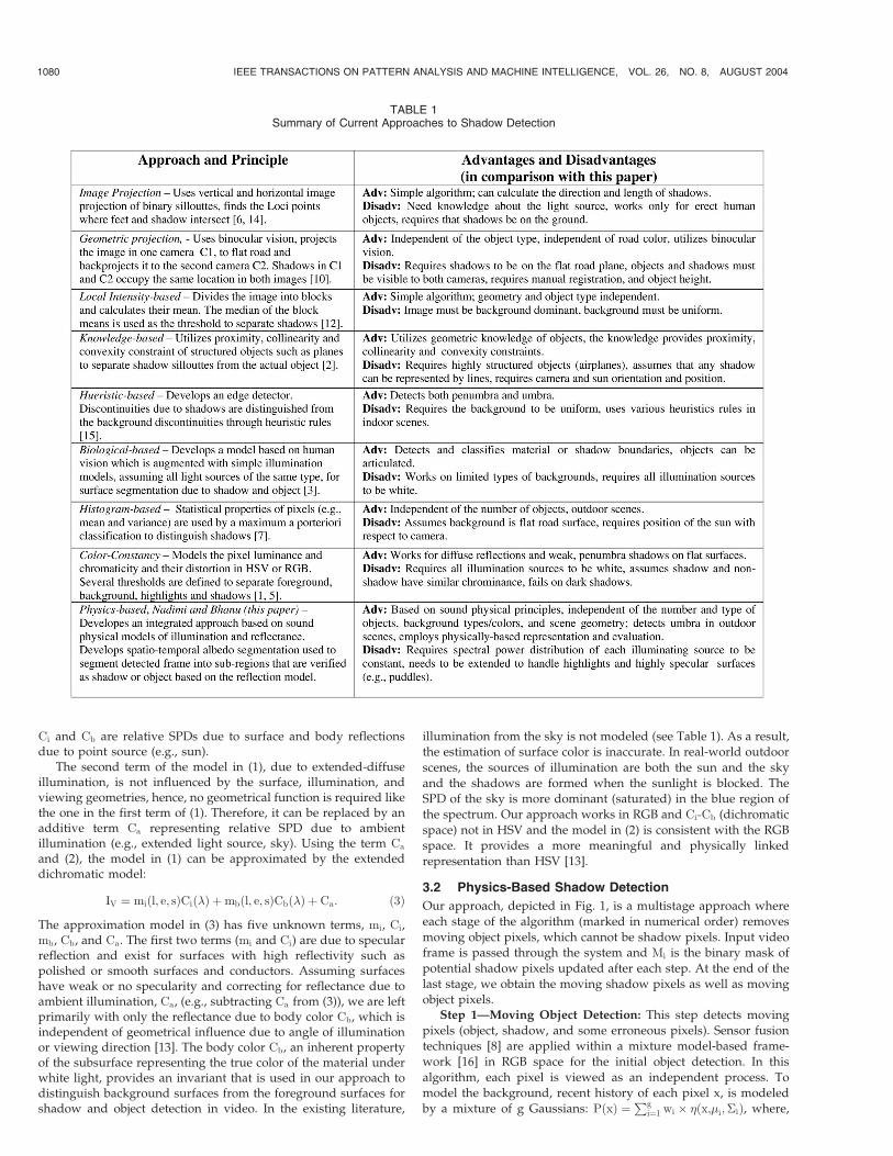
Table 1 provides a summary of approaches for shadow detection.
A comparative study of selected works [1], [5], [7], [15] can be
found in [11].
In comparison with state-of-the-art, the contributions of thispaper are:
1. Integration of different physical models—Sound physicalmodels (dichromatic reflection model, and reflectance-based analysis model) are used in an integrated andprincipled manner. Our approach is different from all theprevious work (see Table 1) in that we make noassumption about surface geometries (e.g., planar versuscurved, horizontal, versus vertical), surface texture (e.g.,grass, brick, tiles, road, etc.), or types and shapes ofshadows, objects, and background. We solely rely onmodels, which can represent wide classes of surfacematerials. In addition, unlike all previous approaches thatmake the assumption of one illumination source (whitelight), our model incorporates multiple sources (sun andsky) with different spectral power distribution (SPD). Theintegrated “realistic” physical models are used for shadowand object detection.
2. Temporal improvement—Spatial albedo ratio test [9], whichis a measure of constant reflectivity of a surface, isextended temporally. The new test is called spatio-temporal albedo ratio test, and it is utilized for surfacesegmentation in video.
3. Experiments and performance evaluation—The algorithm istested on a wide variety of video data consisting of bothvehicles and people. We have provided physically importantindependent variables such as surface types and materials,surface orientation, and time of day, which are physicallylinked to the scene and are used as benchmarks [11] in ourexperiments.
3 TECHNICAL APPROACH
3.1 Shadow Modeling
Consider a single visible light point source (i.e., sun), a diffuseextended light source (i.e., sky), and a Lambertian surface withconstant reflectance. Then, the observed surface intensity value, IV,on a given surface can be calculated by integrating the reflectancefunction over the entire visible spectrum for each light source andthen added.
IV ¼Z
��1
K1L1 �ð Þf l; e; sð Þd�þZ
��2
K2L2 �ð Þd�; ð1Þ
where K1;K2 are the coefficient of reflectances due to sun and sky;L1;L2 are intensity of the illumination sources sun and sky,respectively, f(.) is a geometric term, and the angles are l (incidentangle of illumination), e (angle for viewing direction), and s (anglefor specular reflection). The first term of the model in (1) is due tothe point source and includes both specular and diffuse compo-nents. If the interreflections are negligible, the color of a pixel isonly influenced by the light reaching it and reflected properties ofthe surface.
The first term in (1) can be approximated by several reflectancemodels. In the order of increasing sophistication, surface reflec-tance is modeled by: 1) Lambertian model, 2) Phong model, and3) Dichromatic model [13]. Considering the dichromatic model forthe first term in (1),
I ¼Lð�; l; e; sÞ ¼ Lið�; l; e; sÞ þ Lbð�; l; e; sÞ ¼ miðl; e; sÞCið�Þþmbðl; e; sÞCbð�Þ;
ð2Þ
where L is the total radiance of the reflected light, Li is radiance ofthe light reflected at the surface, and Lb is radiance of the lightreflected from the body. Geometric terms for the surface and bodyare mi and mb, respectively, and the angles are described as before.
IEEE TRANSACTIONS ON PATTERN ANALYSIS AND MACHINE INTELLIGENCE, VOL. 26, NO. 8, AUGUST 2004 1079
. The authors are with the Center for Research in Intelligent Systems,University of California, Riverside, CA 92521.E-mail: {sohail, bhanu}@cris.ucr.edu.
Manuscript received 15 Oct. 2002; revised 10 July 2003; accepted 8 Mar.2004.Recommended for acceptance by R. Kumar.For information on obtaining reprints of this article, please send e-mail to:[email protected], and reference IEEECS Log Number 117583.
0162-8828/04/$20.00 � 2004 IEEE Published by the IEEE Computer Society
Ci and Cb are relative SPDs due to surface and body reflectionsdue to point source (e.g., sun).
The second term of the model in (1), due to extended-diffuseillumination, is not influenced by the surface, illumination, andviewing geometries, hence, no geometrical function is required likethe one in the first term of (1). Therefore, it can be replaced by anadditive term Ca representing relative SPD due to ambientillumination (e.g., extended light source, sky). Using the term Ca
and (2), the model in (1) can be approximated by the extendeddichromatic model:
IV ¼ miðl; e; sÞCið�Þ þmbðl; e; sÞCbð�Þ þ Ca: ð3Þ
The approximation model in (3) has five unknown terms, mi, Ci,mb, Cb, and Ca. The first two terms (mi and Ci) are due to specularreflection and exist for surfaces with high reflectivity such aspolished or smooth surfaces and conductors. Assuming surfaceshave weak or no specularity and correcting for reflectance due toambient illumination, Ca, (e.g., subtracting Ca from (3)), we are leftprimarily with only the reflectance due to body color Cb, which isindependent of geometrical influence due to angle of illuminationor viewing direction [13]. The body color Cb, an inherent propertyof the subsurface representing the true color of the material underwhite light, provides an invariant that is used in our approach todistinguish background surfaces from the foreground surfaces forshadow and object detection in video. In the existing literature,
illumination from the sky is not modeled (see Table 1). As a result,the estimation of surface color is inaccurate. In real-world outdoor
scenes, the sources of illumination are both the sun and the sky
and the shadows are formed when the sunlight is blocked. TheSPD of the sky is more dominant (saturated) in the blue region of
the spectrum. Our approach works in RGB and Ci-Cb (dichromatic
space) not in HSV and the model in (2) is consistent with the RGBspace. It provides a more meaningful and physically linked
representation than HSV [13].
3.2 Physics-Based Shadow Detection
Our approach, depicted in Fig. 1, is a multistage approach where
each stage of the algorithm (marked in numerical order) removes
moving object pixels, which cannot be shadow pixels. Input videoframe is passed through the system and Mi is the binary mask of
potential shadow pixels updated after each step. At the end of the
last stage, we obtain the moving shadow pixels as well as movingobject pixels.
Step 1—Moving Object Detection: This step detects moving
pixels (object, shadow, and some erroneous pixels). Sensor fusiontechniques [8] are applied within a mixture model-based frame-
work [16] in RGB space for the initial object detection. In this
algorithm, each pixel is viewed as an independent process. Tomodel the background, recent history of each pixel x, is modeled
by a mixture of g Gaussians: PðxÞ ¼Pg
i¼1 wi � �ðx;�i;�iÞ, where,
1080 IEEE TRANSACTIONS ON PATTERN ANALYSIS AND MACHINE INTELLIGENCE, VOL. 26, NO. 8, AUGUST 2004
TABLE 1Summary of Current Approaches to Shadow Detection

for each R, G, B channel, P(x) is the probability of observing pixel
value x, � is the Gaussian funtion whose ith mixture component is
characterized by the mean �i, covariance �i, and weight wi. The
moving object detection algorithm is initialized by first collecting
t initial frames, and then estimating the parameters of the mixture
for each pixel by K-means clustering technique. We use the AND
strategy [8] which specifies that an incoming pixel value must be
within three standard deviations of any of its g models in all three
(independent R, G, B) channels to be considered a background
pixel; otherwise, it is classified as a moving pixel. This strategy
provides the highest detection rate in comparison to other fusion
strategies [8]. After the initial detection, the binary mask (M1 in
Fig. 1) contains the moving object, its shadow and noisy isolated
pixels. Our segmentation algorithm (Step 4) needs a background
image, which is simply tracked in memory.
Step 2—Initial Shadow Pixel Reduction: The test at this step
states that pixels on a detected surface cannot be shadow if they have
higher intensity than the actual background. Once we have the
current “segmented” image and the background from Step 1, the
following intensity test is applied to moving objects and shadow
pixels to further reduce their number. Let pfxg be a pixel where
x 2 ðR;G;BÞ is background pixel and x 2 ðr; g;bÞ is foreground
moving object, its shadow, and some erroneous background pixels.
Let M2 ¼ � (initially an empty mask), then
8p 2 M1 if ðpr < pRÞ&ðpg < pGÞ&ðpb < pBÞ ) M2 ¼ M2 [ p: ð4Þ
This test does not reduce the shadow areas, but may successfully
reduce object areas, thus reducing the binary mask and computa-
tion at later steps. In addition, this step also eliminates pixels due
to specular reflection which helps in our diffuse component
estimation (Step 6).Step 3—Blue Ratio Test: This step exploits the observation that
shadow pixels falling on neutral surfaces, such as asphalt roads,
tend to be more blueish. This is also true for many gray structures
such as concrete buildings, walkways, etc. Shadow regions are
illuminated by the sky and sky is assumed to be blue and the only
source of illumination on shadowed regions. Although all RGB
values are lower in the shadow region, we have observed that the
amount by which this reduction occurs is not proportional. This is
used to further refine the shadow segmentation. Let pfxg be defined
as in Step 2, then the ratio (pb=pB) tends to be larger than (pr=pR)
and (pg=pG) in shadow regions. We hypothesize a pixel in the
image under the mask M2 to be a shadow pixel and generate a
mask M3 (initially M3 ¼ �) of hypothesized shadow pixels as:
8p 2 M2 if ½ðpb=pBÞ > ðpr=pRÞ�&½ðpb=pBÞ > ðpg=pGÞ� )M3 ¼ M3 [ p:
ð5Þ
Shadow pixels tend to have lower intensity. They are more
saturated toward blue, and their vectors in RGB space make
smaller angle with the blue axis. Equation (5) is not applied to all
the pixels in mask M2, but to neutral or gray surfaces that have low
saturation (< 0:3). Highly saturated surfaces do not exhibit this
phenomenon due to high selectivity of the reflected color. The
output of this step (M3) provides further reduction in the numberof pixels from Step 2.
Step 4—Albedo Ratio Segmentation: This step performssurface segmentation based on a new spatio-temporal albedo ratiotest. Our surface color estimation algorithm (see Step 6 and Fig. 3)relies on the fact that the image has been segmented into uniformregions; where each region is potentially a shadow. Segmentationalgorithm must define a uniformity test that provides the criterionfor segmentation. In [9], such a criterion is introduced based onspatial albedo ratio of neighboring pixels and is given as:(I1=I2 ¼ �1=�2) where I1; I2 are intensity and �1; �2 are albedo(reflectance) of neighboring pixels. It has been shown [9] that thisratio is independent of reflectance function, illumination directionand intensity, and surface geometry (such as flat versus curvedsurfaces). This ratio is extended to the temporal domain asdescribed below. First, we define the connectivity C of twoneighboring pixels p1 and p2 (see Fig. 2) with intensities u and v asfollows:
Cðp1; p2Þ ¼ 1 if Hðu; vÞj j < T0 Otherwise;
�ð6Þ
where, unlike the ratio of reflectance mentioned in the previouswork [9], [15], we use the following spatio-temporal relation anddefine the following ratios:
R1 ¼utþ1 � ututþ1 þ ut
; R2 ¼vtþ1 � vtvtþ1 þ vt
;Hðu; vÞ ¼ R1 �R2
R1 þR2: ð7Þ
The first two ratios R1 and R2 are temporal ratios; therefore,Hðu; vÞ is the spatio-temporal albedo ratio. If two neighboringpixels belong to the same surface they will have temporal ratiosthat are close together; hence, the spatio-temporal relation will beclose to zero. A small value for T in (6) is chosen to account fornoise and other artifacts. Note that, in the spatio-temporal albedotest, the spatial constancy of the normal to the object surface isassumed. This assumption is propagated to the temporal domainwhere surface normals of neighboring pixels are the same. Thisassumption is valid for both the spatial and temporal domains forrigid bodies. It fails for deformable bodies where the surfacenormal can change over time.
In order to segment the image into regions of uniform reflectance(Step 4A), we spatially segment the image using the connectivitycriterion (6) in a segmentation algorithm that first performs asequential labeling [9]. Since border pixels are not reliable, thealgorithm shrinks the binary mask (of the object and shadow) fromthe previous step by 1 pixel before applying the criterion (6).Furthermore, a size filter (S) removes spurious segments (Step 4B)and a new mask (M4) is generated. The choices for T and the sizefilter (S) are discussed in Section 4.3. If the reflected light reaching
IEEE TRANSACTIONS ON PATTERN ANALYSIS AND MACHINE INTELLIGENCE, VOL. 26, NO. 8, AUGUST 2004 1081
Fig. 2. Two neighboring pixels in the foreground (t + 1) and background (t)
image. Background image contains no moving object/shadow (just the surface
background).
Fig. 1. Different steps of physics-based shadow detection algorithm.

the sensor has both the specular and diffuse components, the ratio in(6) may not produce a meaningful result; therefore, to make thisratio useful, we must assume that the surfaces have little or nospecular component. This assumes that there are few highlights inthe image. Most matte, dielectrics, and natural surfaces have mostlydiffuse reflections. This is usually not a problem in shadow regionswhere specular reflections do not exist.
Step 5—Ambient Illumination Correction: This step removesthe effect of sky illumination. At this step, the input image underthe mask has been segmented into uniform regions. Some of thesegments belong to actual objects and some to the background dueto shadows, but all of them have some uniform reflectanceproperties. Since we do not know which segment belongs to anactual object and which to a background surface, we assume thatall are background surfaces.
According to (3), the shadow model developed in Section 3.1,the reflection due to sky illumination (called ambient reflection) isconsidered as an additive component; therefore, we subtract theforeground pixel values from the background over the maskedarea (M4). The result now contains the values where the reflectancedue to the sky illumination has been eliminated, so only thecontribution from the sun is left. For those regions that belong to anactual object, this subtraction causes the background surface tohave a very different color vector than the color vector expected forthe shadow region. The hypothesis here is that all segmentedsurfaces are due to shadow. If our hypothesis is correct, then weshould be able to correctly find the diffuse color vector due tosunlight only. On the other hand, if our hypothesis is wrong, in thecase of object surfaces with very different color than the back-ground, then we do not expect to get the correct results; hence, inour verification stage, these vectors will not be matched.
Step 6—Body Color Estimation: This step performs body colorestimation (Cb) using a diffuse color estimation algorithm. At thisstep, the input image under the mask has been segmented intoseveral regions and ambient reflection due to sky has beensubtracted from each region. Assuming each segment is a shadow,we obtain the diffuse component (Cb) of the model (2) and thencompare this to our original estimation called, the initial estimate.Two questions now remain: 1) How do we get the Cb from ourcurrent information? 2) How do we measure it in the first place sowe can compare it with our new measurement? We first answerquestion 1), and postpone the answer of 2) to Section 4.2.
The model in (2) is represented by four unknowns, mi, mb, Ci,and Cb, for each pixel. This requires at least four values for a pixel.
These values can be obtained by three different methods: 1) movingthe illumination source, 2) moving the camera, or 3) sampling thepixel values on larger but similar areas. Since we have no controlover the illumination source and assume static camera, the firsttwo methods do not apply. The third method requires a uniformsurface that is obtained at Step 4. The algorithm for estimating thecolor of a surface is given in Fig. 3.
The body color (Cb) is in the form of a 3-dimensional unit vectorin unit RGB space. The vector corresponding to the largesteigenvalue is estimated as the body color. Depending on thesurface type (planar or curved) that matrix M represents, and theviewing geometry, the pixels in matrix M may form point-like,linear, or planar clusters. The eigenvalues and eigenvectorsrepresent the extent and orientation of ellipsoids that fit the data.
Step 7—Verification: This step performsmatching of body colorof various surfaces with the stored body color of materials that weexpect to see in the scene. The algorithm has training and testingphases. In the training phase, we calculate the body color of surfacesthat come under shadow in the scene. This is accomplished byprecomputing the body vectorCb for various surfacematerials suchas concrete, grass, red-brick, asphalt, etc. During the testing phase,for each frame after Step 7, for each segment, we compare the bodycolor vector of the segment with any of the body color vectors in ourdatabase. Assume that the body color of a surface patch is VpVp and thetrue body color of the surface is VtVt, then the angle � between the twovectors is defined as: � ¼ cos�1½ðVpVp � VtVtÞ=ðjjVpVpjj jjVtVtjjÞ�. If this angle issmall, then the two vectors are similar; hence, they indicate similarcolors and belong to the same surface. All the pixels for the segmentwhose vector is just matched, are considered and collected as ashadow binary mask image. Once all the segments are verified, theresult are the detected shadows. The objects are obtained bysubtracting detected shadows from mask M1 that contained bothmoving object and moving shadows.
4 EXPERIMENTAL RESULTS
4.1 Data and Parameters
Video data is obtained with a SONY DCR-VX1000 camera withthree CCD sensors. No filter is used and all the controls for thecamera (shutter speed, aperture, gain control, white balance, etc.)are set in automatic mode. The data consists of moving vehiclesand people with background materials and surfaces found inurban areas, which contain structures such as buildings, houses,
1082 IEEE TRANSACTIONS ON PATTERN ANALYSIS AND MACHINE INTELLIGENCE, VOL. 26, NO. 8, AUGUST 2004
Fig. 4. (a) Background image and (b) foreground image. During the training, a user selects a patch of shadowed region from a frame. Steps 6 and 7 of our algorithm are
then applied and the body color vector Cb is estimated and stored.
Fig. 3. Diffuse color estimation algorithm.

walkways, roads, parks, etc. The range of physical conditions in
our experiments (shown in the heading of examples) include:
1. background surface materials—grass (parks), wood (trees),concrete (buildings), asphalt (roads);
2. foreground surface materials—semipermeable (humanskin), dielectric (clothing), vehicle body;
3. colors—typical uniform surface colors, textured colors,saturated and neutral;
4. surface slopes—vertical, horizontal, slopes (such as a hill);5. sun angle—morning, high noon, early afternoon, late
afternoon; and6. distance to objects: approximately 10-200 feet.
The number of Gaussians (g at Step 1) is fixed at 3.The three parameters that affect our algorithm are: 1) threshold
T = 0.05 selected for surface albedo ratio segmentation (Step 4A),2) size filter S = 10 pixels (Step 4B), and c) the angle threshold� ¼ 1� selected for color equivalency (Step 7). All these thresholds
IEEE TRANSACTIONS ON PATTERN ANALYSIS AND MACHINE INTELLIGENCE, VOL. 26, NO. 8, AUGUST 2004 1083
Fig. 5. Example 1, vehicles casting shadows on asphalt and walkway concrete.

remain constant for all the results shown in the paper. The testvideo data are short sequences (400-4,500 frames); therefore, nobackground update is necessary.
4.2 Performance Evaluation
In order to evaluate the performance of our algorithm, the ground-truth data are obtained for each frame by manually drawing acontour around the moving objects and their shadows. Results areshown using a confusion matrix for shadow (S), object (O), andbackground (B). During the training phase, for the initial
estimation of the diffuse background color, the user selects areasof typical backgrounds when they are shadowed. As shown inFig. 4, after user selection, Steps 6 and 7 are applied to these areasto calculate a table of diffuse color vectors for various materials.This table is used during the testing. Note that the body color of thebackground surface cannot be guaranteed to have the correct colorvector if its reflectance is due to multiple illumination sources ofdifferent SPDs. The effect of sky illumination must first beaccounted for. This is only possible if the other sources (e.g.,sun) can be blocked, the surface reflectance due to sky estimated,
1084 IEEE TRANSACTIONS ON PATTERN ANALYSIS AND MACHINE INTELLIGENCE, VOL. 26, NO. 8, AUGUST 2004
Fig. 6. (a) Example 2 and (b) Example 3. Shadows are cast on different vertical and horizontal surfaces.

and then subtracted from the original background. For testing,
once the moving pixels and associated mask M1 are obtained in
Step 1, they are used as the input to Step 2 of the algorithm. At each
subsequent step of the algorithm, we only need to modify the
image pixels under the mask for computational efficiency.
Example 1. Fig. 5 indicates two examples from two different scenes
with moving vehicles where shadow of vehicles either follows
or precedes them. The scene includes both asphalt with
different texture, and concrete. As indicated by the confusion
matrix for each example, when the initial detection accuracy is
reasonably high, the shadow detection performs well. In frames
31 and 117 of Example 1b, the vehicle windows are not initially
detected where the pixels on the windows of the vehicles are as
dark as the background. Note that the shadow detection
algorithm performs better for cases where both objects and
their shadows are closer to the camera.
IEEE TRANSACTIONS ON PATTERN ANALYSIS AND MACHINE INTELLIGENCE, VOL. 26, NO. 8, AUGUST 2004 1085
Fig. 7. Three examples. (a) Example 4, (b) Example 5, and (c) Example 6.

Example 2. Fig. 6a is representative of different types of back-ground surfaces including vertical, horizontal, textured, uni-form, brick, and concrete. The detection algorithm performedconsistently for all the geometry and surface types present inthis example. As indicated in the confusion matrix, on theaverage 73 percent of shadow pixels are correctly detectedwhile the percentage of object pixels classified as shadow isminimal.
Example 3. Fig. 6b is an example of shadow cast on typicaltextured concrete found in buildings with subject wearing atextured shirt. Despite the noise in the initial detection (Step 1),on the average over 80 percent of the shadow is correctlydetected.
Example 4. Fig. 7a represents an inclined and curved grass surface.As the subject and its shadow move closer to the camera, thedetection improves. This is also an example of a surface thatexhibits highly saturated color and specularities due to thesurface type of grass and angles of incidence. This is achallenging test since we do not account for specularities thatintroduce noise, which affects the estimation of Cb. Due to highsaturation, Step 3 is bypassed.
Example 5. Fig. 7b shows a highly saturated color surface. Thebackground is red polished tile and the foreground subject iswearing textured and uniformed colored clothes. The shadowcast by the moving object on the grass is not initially detected atStep 1; therefore, it is not considered by the rest of thealgorithm. Due to the proximity of the surfaces to each otherthere exist high interreflections that are not modeled in ourapproach.
Example 6. Fig. 7c shows multiple moving objects at differentdistances from the camera. The initial moving object detectionperformed superbly, but shadows of objects at considerabledistances are missed. This is due to the choice of the size filterused at Step 4B. Shadows of objects that are far away aresegmented into smaller segments which are filtered out.
Example 7. Fig. 8 illustrates a difficult shadow and object colorsituation. In this case, part of the object and the shadow havethe same diffuse color—the person’s pant has a neutral graycolor, the same as the background, and it is self-shadowed. As aresult, part of the pant is labeled as shadow. The self-shadowedregion of pant, however, has higher luminance than the realshadow on the ground; hence, we utilize a statistical luminance
test based on histogram analysis to further classify these tworegions as shown.
4.3 Discussion of Experimental Results and Parameters
Accuracy versus Number of Shadow Pixels: Fig. 9 shows thedetection of shadow for Example 4. It shows the percentage ofshadow pixels detected correctly vs. distance of the moving objectto camera and number of (groundtruth) shadow pixels. As theobject comes closer to the camera, its shadow gets larger and thecamera signal becomes better since it is inversely proportional tothe distance of the reflected light. Larger areas with uniformreflectance contribute to larger segments in Steps 4 and 6, thuscontributing to better diffuse color estimation.
Effect of Parameters T and S: Table 2 shows the effect ofparameters T and S. It shows the initial number of segments withuniform reflectance, obtained at Step 4A, with a threshold value ofT = 0.05. A larger value for T will merge smaller segments into alarge segment whose diffuse color component may not be reliabledue to inclusion of several types of surfaces, each with a differentcolor. As indicated by our experiments, we have found that a valueof the threshold T = 0.05 is appropriate. Table 2 also shows that thesize segment threshold (S), Step 4B, greatly reduces the computa-tional load before Step 7. By choosing large segments, we alsoeliminate smaller segments as well that may actually be shadows.This is indicated in Example 6 where several subjects are atdifferent distances to the camera. The initial detection may fail todetect enough pixels on objects that are far away; hence,segmentation may result in many small surfaces that may befiltered out by the choice of S.
Effect of Parameter �: The parameter (�) determines thesensitivity to color vector matching. Plots in Figs. 10a and 10bare receiver operating characteristic curves (ROC) for two different
1086 IEEE TRANSACTIONS ON PATTERN ANALYSIS AND MACHINE INTELLIGENCE, VOL. 26, NO. 8, AUGUST 2004
Fig. 8. Similar foreground and background colors, self-shadowing, and refined shadow. (a) Diffuse color of pant (red) and shadow (blue) for frame 152 in RGB
space. (b) Histogram analysis.
Fig. 9. Effect of shadow size.

scenes (Example 2 and Example 3) that indicate the sensitivity ofthe algorithm to color vector matching angle (�). We use athreshold of 1� for all our examples, which corresponds to valuesat the lower left part of the curves where probability of false alarmis extremely low. The upper bound on the detection rate (Pd) isdependent on the initial moving object detection algorithm, thesize segment threshold, the accuracy of the color estimation, andwhether we consider border pixels or not. In most cases, theuniformity test causes the border pixels for object and shadow tonaturally fall into smaller segments and the size filter eliminatesthem. We have adopted to shrink the object and its shadow by onepixel first. We note that this reduces the detection rate.
5 CONCLUSIONS
In this paper, a novel approach consisting of an original ensembleof techniques for detecting shadows and moving objects based onsound physical models was presented. Experimental resultsdemonstrated that our approach is robust to widely different1) background surfaces, commonly encountered in real-worldurban environments, such as concrete, asphalt, bricks, tiles, andgrass, 2) foreground materials such as human skin, variety ofcolored and textured textiles, metallic surfaces such as vehiclesurfaces, and 3) illumination conditions at different times of theday and locations. Furthermore, the physical attributes such assurface type, surface roughness, and surface orientation andillumination condition were physically associated to the sceneand the detection algorithm as shown in our experimental results.Steps 1, 2, and 3 of our algorithm effectively reduced thecomputational load for potential shadow pixels, whereas Steps 4,5, and 6 provided a new robust method for distinguishing theshadow pixels from the moving object pixels. The spatio-temporalalbedo ratio test provided a criterion for physically driven surfacesegmentation. The surface color estimation is based on a physicalmodel and we have provided a robust method for estimating thebody color of surfaces. The integrated system is implemented inMatlab, which is an interpreted environment, and it takes 4 secondsto complete processing for one frame. This environment is chosenfor its extensive functionality, but it is inherently slow. In thefuture, a real-time implementation at video rate will be explored.
ACKNOWLEDGMENTS
This work was supported in part by grants F49620-02-1-0315 andDAAD19-01-0357; the contents and information do not necessarilyreflect the position or policy of the US Government.
REFERENCES
[1] R. Cucchiara, C. Grana, M. Piccardi, A. Prati, and S. Sirotti, “ImprovingShadow Suppression in Moving Object Detection with HSV ColorInformation,” Proc. IEEE Intelligent Transportation Systems Conf., pp. 334-339, Aug. 2001.
[2] S. Das and B. Bhanu, “A System for Model-Based Object Recognition inPerspective Aerial Images,” Pattern Recognition, vol. 3, no. 34, pp. 465-491,1998.
[3] R. Gershon, A.D. Jepson, and J.K. Tsotsos, “Ambient Illumination and theDetermination of Material Changes,” J. OSA, vol. 3, no. 10, pp. 1700-1707,Oct. 1986.
[4] I. Haritaoglu, D. Harwood, and L. Davis, “W4: Real Time Surveillance ofPeople and Their Activities,” IEEE Trans. Pattern Analysis and MachineIntelligence, vol. 22, no. 8, pp. 809-830, Aug. 2000.
[5] T. Horprasert, D. Harwood, and L.S. Davis, “A Statistical Approach forReal-Time Robust Background Subtraction and Shadow Detection,” Proc.IEEE Int’l Conf. Computer Vision, Frame Rate Workshop, pp. 1-19, 1999.
[6] J.W. Hsieh, W.F. Hu, C.J. Chang, and Y.S. Chen, “Shadow Elimination forEffective Moving Object Detection by Gaussian Shadow Modeling,” Int’l J.Image and Vision Computing, vol. 21, pp. 505-516, 2003.
[7] I. Mikic, P.C. Cosman, G.T. Kogut, and M.M. Trivedi, “Moving Shadow andObject Detection in Traffic Scenes,” Proc. Int’l Conf. Pattern Recognition,vol. 1, no. 1, pp. 321-324, 1998.
[8] S. Nadimi and B. Bhanu, “Multistrategy Fusion Using Mixture Model forMoving Object Detection,” Proc. Int’l Conf. Multisensor Fusion and Integrationfor Intelligent Systems, pp. 317-322, 2001.
[9] S.K. Nayar and R.M. Bolle, “Reflectance Based Object Recognition,” Int’l J.Computer Vision, vol. 17, no. 3, pp. 219-240, 1996.
[10] K. Onoguchi, “Shadow Elimination Method for Moving Object Detection,”Proc. Int’l Conf. Pattern Recognition, vol. 1, no. 2, pp. 583-587, 1998.
[11] A. Prati, I. Mikic, M.M. Trivedi, and R. Cucchiara, “Detecting MovingShadows: Algorithms and Evaluation,” IEEE Trans. Pattern Analysis andMachine Intelligence, vol. 25, no. 7, pp 918-923, July 2003.
[12] J.M. Scanlan, D.M. Chabries, and R.W. Christiansen, “A Shadow Detectionand Removal Algorithm for 2-D Images,” Proc. Int’l Conf. Acoustics, Speechand Signal Processing, vol. 4, pp. 2057-2060, 1990.
[13] S.A. Shafer, “Using Color to Separate Reflection Components,” ColorResearch and Application, vol. 10, no. 4, pp. 210-218, 1985.
[14] Y. Sonada and T. Ogata, “Separation of Moving Objects and Their Shadows,and Application to Tracking of Loci in the Monitoring Images,” Proc. Int’lConf. Signal Processing, vol. 2, no. 2, pp. 1261-1264, 1998.
[15] J. Stauder, R. Mech, and J. Ostermann, “Detection of Moving Cast Shadowsfor Object Segmentation,” IEEE Trans. Multimedia, vol. 1, no. 1, pp. 65-76,Mar. 1999.
[16] C. Stauffer and W.E.L. Grimson, “Learning Patterns of Activity Using Real-Time Tracking,” IEEE Trans. Pattern Analysis and Machine Intelligence, vol. 22,no. 8, pp 747-757, Aug. 2000.
. For more information on this or any other computing topic, please visit ourDigital Library at www.computer.org/publications/dlib.
IEEE TRANSACTIONS ON PATTERN ANALYSIS AND MACHINE INTELLIGENCE, VOL. 26, NO. 8, AUGUST 2004 1087
TABLE 2Number of Segments after Segmentation (Step 4A), Size Filter (Step 4B), and Verification (Step 7)
Fig. 10. ROC plots—(a) frame 344 of Example 2 and (b) frame 360 of Example 5.