physically-based failure models and criteria for …physically-based failure models and criteria for...
TRANSCRIPT

Physically-based failure models and criteria
for laminated fibre-reinforced composites
with emphasis on fibre kinking.
Part I: Development
S T Pinho ∗, L Iannucci and P Robinson
Department of Aeronautics, South Kensington Campus, Imperial College London,
SW7 2AZ, London, U.K.
Abstract
3D failure criteria for laminated fibre-reinforced composites, based on a physical
model for each failure mode and considering nonlinear matrix shear behaviour, are
developed. Special emphasis is given to compression failure. The physical model for
matrix compression failure is based on the Mohr-Coulomb criterion and also predicts
the fracture angle. For fibre kinking, an initial fibre-misalignment angle is considered
to trigger failure, due to further rotation during the compressive loading. The plane
where the kinking takes place is predicted by the model, as well as the kink-band
angle. Applications are presented that validate the model against experimental data.
Key words: A Carbon Fibre, B Fracture, C Analytical Modelling, Failure
∗ Corresponding author. Tel. +4402075945107, Fax. +4402075848120Email addresses: [email protected] (S T Pinho),
[email protected] (L Iannucci), [email protected] (P
Preprint submitted to Elsevier Science 22 April 2005

1 Introduction
The mechanisms that lead to failure in composite materials are not fully under-
stood yet. This is especially true for compression failure, both for the matrix
and fibre-dominated failure modes. This has become particularly evident after
the World Wide Failure Exercise (WWFE) [1].
This series of two papers covers two main themes. In this first paper, physically-
based failure models are discussed and proposed for each failure mode in lam-
inated fibre-reinforced composites with unidirectional plies, at the ply level.
The failure analysis of laminated composites, considering fibre-dominated fail-
ure modes and matrix-dominated failure modes can be tracked back to Hashin
[2,3].
Experimental results from the World Wide Failure Exercise (WWFE) [1,4]
indicate that the (admittedly scarce) data on fibre tensile failure under bi-
or multi-axial stress states does not seem to invalidate the maximum stress
criterion. Thus, this paper focuses on models for compression failure, which is
of great interest in crashworthiness and other areas, as well as matrix tensile
failure.
In this work, accurate physically-based criteria are developed and preferred to
curve-fitting-based criteria. The main limitation associated with curve-fitting-
based criteria is that their applicability is restricted to the load combinations
used in the curve fitting from which they originate. However, it is impractical
to test every material in enough load combinations to define these criteria for
every combination of the six stress tensor components.
Robinson).
2

Matrix compression failure is addressed with a model based on the Mohr-
Coulomb criterion. Puck et al. [5–8] were the first researchers to propose a
matrix failure model based on the Mohr-Coulomb criterion. Further devel-
opments were later carried by Davila et al. [9,10] for the LaRC02/03 failure
criteria. In this present work, an analysis of both Puck [7,8] and LaRC02/03
[9,10] matrix compression failure criteria is performed. For the LaRC02/03
criteria, a correction is proposed for the consideration of friction stresses. This
leads to more conservative predictions, and makes the resulting failure enve-
lope coincide with a simpler criterion that can be related to the work from
Puck and Schurmann [7,8]. The analysis concludes with the proposal of the
latter as a matrix failure criterion for a three dimensional (3D) stress state.
Matrix tensile failure is addressed combining the action or fracture plane con-
cept from Puck and Schurmann [7,8] with experimental evidence from the
WWFE.
For fibre failure in compression, a review [11] suggests kink-band formation
results from matrix failure, due to small misalignments of the fibres in the
composite. Also, the review indicates shear nonlinearity should have a con-
siderable effect on failure and 2D analyses of fibre kinking over-simplify the
treatment of the problem. In this present work, a formal treatment of fibre
kinking is presented, that leads to a model for fibre kinking similar to the
one proposed by Davila et al. [9,10]. The main differences are that the model
presented here accounts for 3D effects, considers a generic nonlinear shear
behaviour, and uses the matrix failure criteria developed in this paper.
In the second paper of the series [12], the implementation of the failure models
into a commercial explicit FE code [13] is described. After failure is initiated,
the failure process is smeared over the finite element dimension. This allows
3
for constant energy absorption, regardless of mesh refinement. The resulting
FE model is shown to have captured some interesting features of the failure
process.
In this paper, the index a refers to the fibre direction, the index b refers to
the in-plane transverse direction and the index c refers to the through-the-
thickness direction.
2 Fibre tensile failure
For fibre tensile failure, it is somewhat difficult to argue whether stresses
other than σa contribute to promote failure and have any influence on the
strength. For instance, Soden et al. [4] obtained experimental data to define
the (σa, τab) failure envelope of CFRP, and the (σa, σb) failure envelope of
GRP. From their results, it does not seem possible to draw sound conclusions
on how the different stress components interact to promote failure. Therefore
the maximum stress failure criterion is used:
fft =σa
Xt
= 1. (1)
3 Matrix compression failure
3.1 Mohr-Coulomb based criteria
The orientation of the fracture surface of specimens failing by matrix com-
pression suggests that the Mohr-Coulomb criterion is applicable to matrix
compression failure [5–8]. Matrix compression specimens fail by shear. For a
4
b
c
a
φ
LτTτ
nσ
σ
τ
cY− 2cY−
bcS
oφ2
oφ2
(a) (b )
(c ) (d )
2.6mm b
c φο
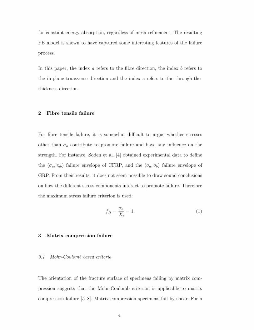
Fig. 1. (a) Pure transverse compression failure, for a CFRP specimen; (b) Frac-
ture plane for a 3D stress state; (c) stresses in the fracture plane; (d) geometrical
representation of the Mohr-Coulomb criterion
pure compression loading, this fact suggests that the angle of the fracture sur-
face with the through-the-thickness direction should be φo = 45◦, i.e. fracture
should occur in the plane of the maximum shear stresses. However, it is ex-
perimentally seen that the angle is generally φo = 53 ± 2◦ for most technical
composite materials [7,8], Fig. 1(a). This can be explained through the exis-
tence of a compressive stress acting on the potential fracture surfaces, and an
associated friction stress.
The designation ‘friction stress’ is here used, as it was by previous authors
[7,8], even though there is no interface before fracture. At the micro-mechanical
level, the effective macro-mechanical friction stress can be explained, at least
partially, as resulting from the ‘true’ friction stress acting in the micro-cracks
in the matrix before failure.
For a general loading situation, Fig. 1(b), the angle of the fracture plane with
the through-the-thickness direction, denoted as φ, might assume a different
value than the one for pure compression (φo). The particular orientation of
5

the fracture plane depends on the particular combination of shear (τT and τL)
and normal (σn) tractions for each particular value of φ, Fig. 1(c).
In a 3D formulation, the tractions are obtained from the components of the
stress tensor and the fracture plane angle φ:
σn =σb + σc
2+
σb − σc
2cos (2φ) + τbc sin (2φ)
τT = −σb − σc
2sin (2φ) + τbc cos (2φ)
τL = τab cos (φ) + τca sin (φ) .
(2)
The Mohr-Coulomb failure criterion is expressed in terms of the tractions in
the fracture plane, and can be written in several forms. Considering first the
case where τL = 0, the Mohr-Coulomb criterion can be expressed as
|τT |+ µT σn = ST (σn < 0) (3)
where µT is a friction coefficient and ST is the fracture plane fracture resistance
against its fracture by transverse shear 1 . For simplicity, ST is not considered
to depend on φ, and will be designated as transverse shear strength. For a
more detailed explanation on the difference between fracture plane fracture
resistance and strength, see Ref. [7]. The geometrical representation of this
criterion in a (σ,|τ |) space is a line with negative slope (−µT ), shown in Fig.
1(d). In this figure, the Mohr-Coulomb criterion’s line is tangential to the
Mohr circle corresponding to the case of failure by pure compression. The
slope of the Mohr-Coulomb criterion’s line can be related to the angle of the
1 The fracture plane resistance of a potential fracture plane parallel to the fibres
is the resistance of this plane against its fracture due to a single stressing acting in
this plane [8].
6

fracture plane in pure compression, φo, through
tan(2φo) = − 1
µT
. (4)
Furthermore, writing Eq. 3 for a pure compression case establishes the relation
between ST , Yc and φo [14]:
ST =Yc
2 tan (φo). (5)
The angle φo can be easily determined from simple compression tests, Fig.
1(a), and allows the determination of µT and ST by using Eqs. 4 and 5.
The Mohr-Coulomb criterion (Eq. 3) can be expressed in several forms, namely
considering that friction affects (increases) the strength, or that it affects (de-
creases) the applied stress. Probably motivated by those two different forms
of expressing the same criterion for τL = 0, Puck and Schurmann [7,8] initially
proposed for the general case (τL 6= 0)
fmc =
(τT
ST − µT σn
)2
+
(τL
SL − µLσn
)2
= 1, (6)
whereas Davila et al. proposed first for the LaRC02 [9] failure criteria and
subsequently for the LaRC03 [10] failure criteria
fmc =
(〈|τT |+ µT σn〉ST
)2
+
(〈|τL|+ µLσn〉SL
)2
= 1 (7)
where SL is the longitudinal shear strength (for simplicity, SL is considered
not to depend on φ) and the operator 〈·〉 is the Mc-Cauley bracket defined
by 〈x〉 = max {0, x} , x ∈ R. Clearly, Puck and Schurmann (Eq. 6) consider
that the compression stress (σn) increases the effective strength, while Davila
et al. (Eq. 7) consider that the compression stress reduces the effective shear
stress. Puck and Schurmann [7,8] finally choose to use the following equation,
7

arguing that it fits the experimental data better:
fmc =(τT )2
S2T − 2µT ST σn
+(τL)2
S2L − 2µLSLσn
= 1. (8)
For the friction coefficient µL in Eqs. 6, 7 and 8, Puck and Schurmann [7]
proposed to use the following equation
µL
SL
=µT
ST
(9)
in the absence of biaxial experimental data. This suggestion has later been
considered by Davila et al. for the LaRC02/03 criteria [9,10].
3.2 Comparison and Improvements
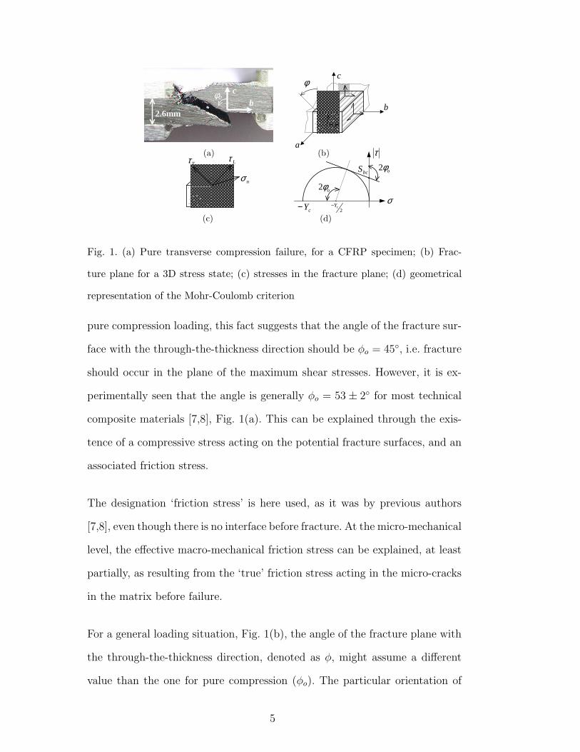
The comparison of the criteria expressed in Eqs. 6, 7 and 8 is shown in Fig. 2
for a material with the properties presented in Table 1. In Fig. 2, the fracture
angle for each point in each curve was determined by trying several tentative
angles, as explained later in this subsection.
While the initial and final Puck criteria (Eqs. 6 and 8) yield similar results,
LaRC02/03 criterion (Eq. 7) is less conservative. This is related to the fact
that the effect of friction is over-estimated in Eq. 7. Indeed, affecting the
shear tractions by a friction term as in Eq. 7 over-estimates the friction forces
whenever both τT and τL are acting simultaneously. As Fig. 3(a) represents,
supposing a very simple case with isotropic friction (µT = µL), the friction
stresses are over-estimated by a factor of√
2 when using Eq. 7.
It is interesting to notice the effect that an orthotropic friction model has on
8
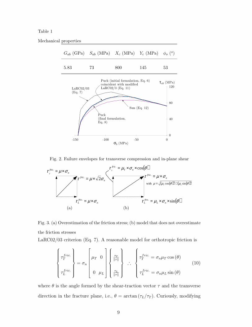
Table 1
Mechanical properties
Gab (GPa) Sab (MPa) Xc (MPa) Yc (MPa) φo (o)
5.83 73 800 145 53
0
4 0
8 0
1 2 0
- 1 5 0 - 1 00 - 5 0 0σb ( M P a )
τa b ( M P a )
S u n ( E q . 1 2 )
L a R C 02 / 03( E q . 7 )
P u c k ( i n i t i a l f o r m u l a t i o n , E q . 6 ) c o i n c i d e n t w i t h m o d i f i e d L a R C 02 / 3 ( E q . 1 1 )
P u c k( f i n a l f o r m u l a t i o n , E q . 8 )
Fig. 2. Failure envelopes for transverse compression and in-plane shear
nfric
L σµτ ×=.
nfric
Tσµτ ×=.
nfric σµτ 2. ×=
( )θσµτ sin. ××= nLfric
L
( )θσµτ cos. ××= nTfric
T
nfric σµτ ×=.
( )( ) ( )( )22 sincoswith θµθµµ LT +=
(a) (b )
Fig. 3. (a) Overestimation of the friction stress; (b) model that does not overestimate
the friction stresses
LaRC02/03 criterion (Eq. 7). A reasonable model for orthotropic friction is
τ fric.T
τ fric.L
= σn
µT 0
0 µL
τT
‖τ‖
τL
‖τ‖
∴
τ fric.T = σnµT cos (θ)
τ fric.L = σnµL sin (θ)
(10)
where θ is the angle formed by the shear-traction vector τ and the transverse
direction in the fracture plane, i.e., θ = arctan (τL/τT ). Curiously, modifying
9
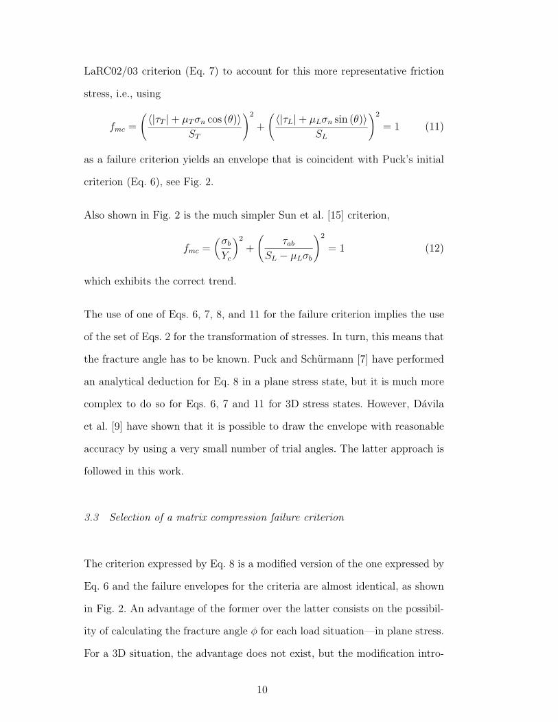
LaRC02/03 criterion (Eq. 7) to account for this more representative friction
stress, i.e., using
fmc =
(〈|τT |+ µT σn cos (θ)〉ST
)2
+
(〈|τL|+ µLσn sin (θ)〉SL
)2
= 1 (11)
as a failure criterion yields an envelope that is coincident with Puck’s initial
criterion (Eq. 6), see Fig. 2.
Also shown in Fig. 2 is the much simpler Sun et al. [15] criterion,
fmc =(
σb
Yc
)2
+
(τab
SL − µLσb
)2
= 1 (12)
which exhibits the correct trend.
The use of one of Eqs. 6, 7, 8, and 11 for the failure criterion implies the use
of the set of Eqs. 2 for the transformation of stresses. In turn, this means that
the fracture angle has to be known. Puck and Schurmann [7] have performed
an analytical deduction for Eq. 8 in a plane stress state, but it is much more
complex to do so for Eqs. 6, 7 and 11 for 3D stress states. However, Davila
et al. [9] have shown that it is possible to draw the envelope with reasonable
accuracy by using a very small number of trial angles. The latter approach is
followed in this work.
3.3 Selection of a matrix compression failure criterion
The criterion expressed by Eq. 8 is a modified version of the one expressed by
Eq. 6 and the failure envelopes for the criteria are almost identical, as shown
in Fig. 2. An advantage of the former over the latter consists on the possibil-
ity of calculating the fracture angle φ for each load situation—in plane stress.
For a 3D situation, the advantage does not exist, but the modification intro-
10

duced means Eq. 8 does not correctly represent the Mohr-Coulomb criterion.
Therefore, for 3D applications, Eq. 6 is preferred over Eq. 8.
As discussed, Eq. 7 over-estimates the friction stresses. Correcting this results
in Eq. 11, which correctly applies the Mohr-Coulomb criterion, assuming that
the compression reduces the shear stresses. Assuming instead that compression
increases the strength results in Eq. 6. Both Eqs. 6 and 11 are physically sound.
Finally, since Eqs. 6 and 11 yield similar results, but the former is simpler,
Eq. 6 is selected as the matrix compression failure criterion (i.e. for σn < 0)
in this paper.
4 Matrix tensile failure
It can be concluded from the WWFE’s experimental results [4], that a quadratic
interaction between the transverse stress σb and the in-plane shear stress τab
describes appropriately the (σb, τab) failure envelope, for the matrix tensile
failure mode. Davila et al. [9] used this interaction criterion for the LaRC02
failure criteria. However, for the (σb, τab) failure envelope, the fracture plane
is always parallel to the (a, c) plane.
For a generic stress state, the matrix tensile fracture plane does not coincide
necessarily with the (a, c) plane. Therefore, it seems reasonable to recast the
tractions expressed in the potential fracture planes—as expressed in Eq. 2—
and apply a quadratic interaction as follows:
fmt =(
σn
Yt
)2
+(
τT
ST
)2
+(
τL
SL
)2
= 1. (13)
The criterion applies for σn ≥ 0, and Yt is the in-plane transverse tensile
11
cX−
�θ
aσ
bσ
b
a
��σ
��σ �θ
cX−
β
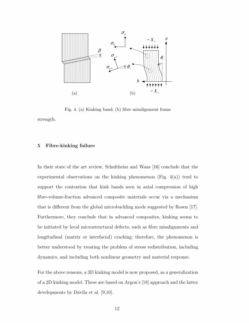
(a) (b)
Fig. 4. (a) Kinking band; (b) fibre misalignment frame
strength.
5 Fibre-kinking failure
In their state of the art review, Schultheisz and Waas [16] conclude that the
experimental observations on the kinking phenomenon (Fig. 4(a)) tend to
support the contention that kink bands seen in axial compression of high
fibre-volume-fraction advanced composite materials occur via a mechanism
that is different from the global microbuckling mode suggested by Rosen [17].
Furthermore, they conclude that in advanced composites, kinking seems to
be initiated by local microstructural defects, such as fibre misalignments and
longitudinal (matrix or interfacial) cracking; therefore, the phenomenon is
better understood by treating the problem of stress redistribution, including
dynamics, and including both nonlinear geometry and material response.
For the above reasons, a 3D kinking model is now proposed, as a generalization
of a 2D kinking model. These are based on Argon’s [18] approach and the latter
developments by Davila et al. [9,10].
12

5.1 2D kinking model
Argon [18] assumed that an initial fibre misalignment exists in the composite,
which leads to shearing stresses between the fibres. The shearing stresses would
act as to further rotate the fibres, which would in turn lead to further increase
in the shear stresses. This ‘closed loop’ effect could then lead to failure. The
main result from his analysis is the relation between the compression failure
stress, Xc, the matrix longitudinal shear failure stress, SL, and the initial fibre
misalignment angle θi (in radians):
Xc =SL
θi
. (14)
Budiansky [19] later extended Argon’s analysis to
Xc =SL
θi + γo(15)
where γo is the shear strain at failure. Failure occurs when the shear fail-
ure stress is reached in the material coordinate system. In a later analytical
work, Budiansky and Fleck [20] included the effect of strain-hardening, shear
loads, kink-band inclination and finite fibre stiffness, obtaining a non closed-
form solution. Another similar solution was obtained assuming kinking in the
transverse direction [21] (but not for any generic direction). Analytical models
for kink-band broadening were also developed [21]. Kyriakides et al. [22] car-
ried micro-mechanical 2D FE models of the kinking process (modelling fibre
and matrix individually), including matrix nonlinearity and initial imperfec-
tions. The micro-mechanical 2D FE models were successfully used to predict
the propagation stress during kink band broadening [23,24].
More recently, Davila et al. [9,10] used a very interesting combination of Ar-
13

gon’s approach [18] and the LaRC02/03 matrix failure criterion. Essentially,
Davila et al. suppose that the fibres might be misaligned, and that further rota-
tion will occur during compressive loading. They then compute the stresses in
the updated misalignment frame and check for matrix failure using LaRC02/03
matrix failure criterion.
In the following, the subscript m applied to the shear stress and shear strain
designates the misalignment frame at failure, and the subscript mc (also ap-
plied to the shear stress and shear strain) designates the misalignment frame
at failure for pure axial compression.
Consider a unidirectional composite with a misaligned region being com-
pressed, as depicted in Fig. 4(b). The stresses in the misalignment frame are,
for a generic plane stress loading
σam =σa + σb
2+
σa − σb
2cos (2θ) + τab sin (2θ)
σbm =σa + σb
2− σa − σb
2cos (2θ)− τab sin (2θ)
τambm = −σa − σb
2sin (2θ) + τab cos (2θ) .
(16)
For failure under pure compression (σa = −Xc, σb ≡ τab = 0), Eqs. 16 lead to
σam = −Xc cos2 (θ) , σbm = −Xc sin2 (θ) and τambm = τmc = Xc sin (θ) cos (θ) .
(17)
This stress state can now be placed in an appropriate matrix failure criterion.
Using Puck’s initial criterion [7] or LaRC02/3 [9,10], Eqs. 6 and 7 respectively
(they yield the same result in this case), gives the expression for the specific
value of the misalignment angle θ at failure for a pure compression case—θc :
Xc
(sin (θc) cos (θc)− µL sin2 (θc)
)= SL. (18)
14

This angle, θc, is the sum of the initial misalignment and the rotation due to
loading. Davila et al. [9] have solved Eq. 18 for θc resulting in
θc = arctan
1−√
1− 4(
SL
Xc+ µL
)SL
Xc
2(
SL
Xc+ µL
)
. (19)
Davila et al. pointed out that neglecting µL and the shear strain, and assuming
θc to be small (in Eq. 18) yields Argon’s equation (Eq. 14). In fact, assuming
all the above but now not neglecting the shear strain yields Budiansky’s Eq.
15.
Using the shear constitutive law, the shear strain γmc can be obtained from the
shear stress τmc and so the initial misalignment angle, θi, can be calculated.
In practice, the shear constitutive law is usually nonlinear so that the shear
strain can be related to the shear stress by the generic function fCL such that
τ = fCL(γ). From the constitutive law, the shear stress at failure (and in the
material axes) is a function of the shear strain
τmc = fCL(γmc) (20)
and from the transformation equations (Eqs. 17), the shear stress at an angle
θc is
τmc =1
2sin (2θc) Xc. (21)
From Eqs. 20 and 21, the shear strain at failure for a pure axial compression
case, γmc, comes as
γmc = f−1CL
(1
2sin (2θc) Xc
). (22)
For instance, for a material which is linear in shear, Eq. 22 becomes simply
γmc =sin (2θc) Xc
2Gab
. (23)
Davila et al. [9] assumed small angle approximations and reached a simpler
15

expression for Eq. 23:
γmc =θcXc
Gab
. (24)
The initial misalignment angle can then be calculated using
θi = θc − γmc (25)
where γmc can be defined by Eqs. 22, 23 or 24.
The initial misalignment angle θi is a material property, and could be regarded
as an equivalent angle that embodies microstructural defects (that can trigger
kink-band formation) as well as the actual initial misalignment, like oscilla-
tions in the fibre volume fraction or in the bonding to the resin, or microcracks
in the resin. Knowing θi allows the establishment of an equation defining the
shear strain in the material axes for a generic plane stress situation, γm, by
using the transformation Eqs. 16 and the shear law:
fCL(γm) = −σa − σb
2sin (2 (θi + γm)) + |τab| cos (2 (θi + γm)) . (26)
Having solved the previous equation for γm, the misalignment angle θ come
then as
θ =τab
|τab| (θi + γm) . (27)
Note that, in Eq. 26, a modulus was applied to τab because it is the easiest
way of considering simultaneously the possibility of an initial misalignment
±θi.
For a nonlinear shear response, Eq. 26 can be solved by an iterative process to
yield γm. For most practical cases, Eq. 26 can be simplified without significant
error by assuming small angle approximations:
fCL(γm) ≈ (θi + γm) (−σa + σb) + |τab| . (28)
16
For a linear shear behaviour, Eq. 28 can be solved [9], resulting in
γm =θiGab + |τab|Gab + σa − σb
− θi. (29)
However, for a nonlinear shear behaviour, there might be no easy way of
solving Eq. 28 or 26 without iterating. Having determined the misalignment
frame, the stresses can be rotated to that frame, and a matrix failure criterion
can be used to check for possible kink-band formation. Davila et al. [9,10]
applied the LaRC02/03 matrix failure criterion to predict failure.
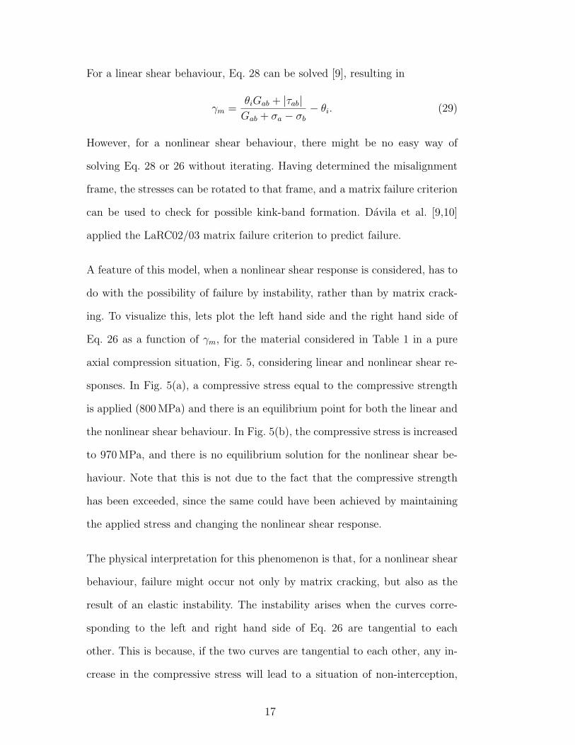
A feature of this model, when a nonlinear shear response is considered, has to
do with the possibility of failure by instability, rather than by matrix crack-
ing. To visualize this, lets plot the left hand side and the right hand side of
Eq. 26 as a function of γm, for the material considered in Table 1 in a pure
axial compression situation, Fig. 5, considering linear and nonlinear shear re-
sponses. In Fig. 5(a), a compressive stress equal to the compressive strength
is applied (800 MPa) and there is an equilibrium point for both the linear and
the nonlinear shear behaviour. In Fig. 5(b), the compressive stress is increased
to 970 MPa, and there is no equilibrium solution for the nonlinear shear be-
haviour. Note that this is not due to the fact that the compressive strength
has been exceeded, since the same could have been achieved by maintaining
the applied stress and changing the nonlinear shear response.
The physical interpretation for this phenomenon is that, for a nonlinear shear
behaviour, failure might occur not only by matrix cracking, but also as the
result of an elastic instability. The instability arises when the curves corre-
sponding to the left and right hand side of Eq. 26 are tangential to each
other. This is because, if the two curves are tangential to each other, any in-
crease in the compressive stress will lead to a situation of non-interception,
17

(a) (b )
�
� �
� ���
� � �
� ��� ��� ��� ��� �� �� ��� ���γ
τ � ������
������ � � ��� � �������� �!#" �$� ��� �% � � �& � �(' )�& � ���&$) ��* � �����
�+��� � � ��� � �,������ �!-" ���� � �& � �(' )�& � ���&$) �$* � ����� . � �& � � / �� �� � �& � �
0 ! � &1' '� �$! � !1� ��
2
3 2
4 2�2
4 3 2
2 2�5 2�6 2�5 2�7 25 2�8 2�5 2�9γ
τ : ;�<>=�?
@>A�B C BED F+G�HIB J�KD L D M�C D K�NO H�D G�P(Q H�C(G�H�G�L D G�B R$C(F A�B R$CM�B AR S�D H�K�C
T�J�KD L D M�C D K�N O H�D G�PQ H�C(L D G�B R1CUF A�B R$CM�B A�R$S�D H�K�C V D G�B$R C
WUH$GL D G�B R1C
X P C B F FC H$P R P D H�G
Fig. 5. (a) Equilibrium point for a linear and a nonlinear material in shear; (b)
equilibrium only for the linear shear behaviour
and thus in unlimited rotation of the fibres (instability). The stress states and
corresponding shear strain corresponding to failure by instability can thus be
mathematically defined by the system
fCL(γm) = −σa − σb
2sin (2 (θi + γm)) + |τab| cos (2 (θi + γm))
∂fCL(γm)∂γm
= − (σa − σb) cos (2 (θi + γm))− 2 |τab| sin (2 (θi + γm)) .
(30)
This system (Eq. 30) defines an envelope for failure by instability. Fibre kink-
ing is thus predicted not only if the matrix failure criterion (in the misalign-
ment frame) is verified, but also if the system (Eq. 30) is verified.
5.2 Proposed 3D kinking model
Most fibre-kinking models assume that kinking happens in the plane of the
lamina. On the other hand, most experimental studies mimic this in-plane
approach and constrain the specimens so that out of plane movements are not
allowed. However, many researchers agree on the 3D nature of fibre-kinking
failure. A 3D kinking model based on the previous 2D model is now proposed.
18

This model assumes initial fibre misalignment and nonlinear shear behaviour.
Furthermore, its formulation is such that an efficient numerical FE implemen-
tation is possible.
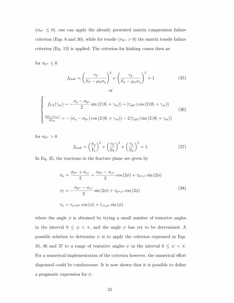
Consider a unidirectional lamina under a general compressive stress state as
shown in Fig. 6(a). The fibre-kinking plane is assumed to be at an angle ψ
with the b axis, as shown in Fig. 6(b). Fig. 6(c) shows the stresses acting on
the (b, c) plane, while Fig. 6(d) shows the stresses acting along the bψ and cψ
directions (Fig. 6(d) assumes that bψ and cψ are the principal directions in
the plane (b, c)). The rotation to the misalignment plane is shown in Fig. 6(e).
The matrix fracture plane is represented in Fig. 6(f). The value of the angle ψ
depends on the particular stress state 2 . A 2D fibre-kinking model—in which
through-the-thickness movements are constrained—assumes that the angle ψ
in Figs. 6(b), (c) and (d) is equal to zero. If the composite is constrained so
that it cannot move in the b direction, then the fibre-kinking plane would have
an angle ψ = 90◦. For a general load situation, ψ will have a value between 0
and 180◦.
The set of transformation Eqs. 31 can now be used to rotate the stresses to
2 In reality, defects such as fibre initial misalignment may not be homogeneously
distributed and the kinking plane could in fact also be influenced by that
19
the fibre-kinking plane:
σbψ =σb + σc
2+
σb − σc
2cos (2ψ) + τbc sin (2ψ)
σcψ = σb + σc − σbψ
τabψ = τab cos (ψ) + τca sin (ψ)
τbψcψ = −σb − σc
2sin (2ψ) + τbc cos (2ψ)
τcψa = τca cos (ψ)− τab sin (ψ) .
(31)
After defining the fibre-kinking plane, the stresses are then rotated to the mis-
alignment frame. The strain γm is obtained by solving the iterative equation
fCL(γm) = −σa − σbψ
2sin (2 (θi + γm)) + |τabψ | cos (2 (θi + γm)) (32)
and the angle θ come as
θ =τabψ
|τabψ | (θi + γm) . (33)
Having established the orientation of the misalignment frame, the stresses can
be rotated to it using
σam =σa + σbψ
2+
σa − σbψ
2cos (2θ) + τabψ sin (2θ)
σbm = σa + σbψ − σam
τambm = −σa − σbψ
2sin (2θ) + τabψ cos (2θ)
τbmcψ = τbψcψ cos (θ)− τcψa sin (θ)
τcψam = τcψaψ cos (θ) .
(34)
At this point, a check can be performed for matrix failure. For compression
20
(σbm ≤ 0), one can apply the already presented matrix compression failure
criterion (Eqs. 6 and 30), while for tensile (σbm > 0) the matrix tensile failure
criterion (Eq. 13) is applied. The criterion for kinking comes then as:
for σbm ≤ 0
fkink =
(τT
ST − µT σn
)2
+
(τL
SL − µLσn
)2
= 1 (35)
or
fCL(γm) = −σa − σbψ
2sin (2 (θi + γm)) + |τabψ | cos (2 (θi + γm))
∂fCL(γm)∂γm
= − (σa − σbψ) cos (2 (θi + γm))− 2 |τabψ | sin (2 (θi + γm))
(36)
for σbm > 0
fkink =(
σn
Yt
)2
+(
τT
ST
)2
+(
τL
SL
)2
= 1. (37)
In Eq. 35, the tractions in the fracture plane are given by
σn =σbm + σcψ
2+
σbm − σcψ
2cos (2φ) + τbmcψ sin (2φ)
τT = −σbm − σcψ
2sin (2φ) + τbmcψ cos (2φ)
τL = τambm cos (φ) + τcψam sin (φ)
(38)
where the angle φ is obtained by trying a small number of tentative angles
in the interval 0 ≤ φ < π, and the angle ψ has yet to be determined. A
possible solution to determine ψ is to apply the criterion expressed in Eqs.
35, 36 and 37 to a range of tentative angles ψ in the interval 0 ≤ ψ < π.
For a numerical implementation of the criterion however, the numerical effort
dispensed could be cumbersome. It is now shown that it is possible to define
a pragmatic expression for ψ.
21
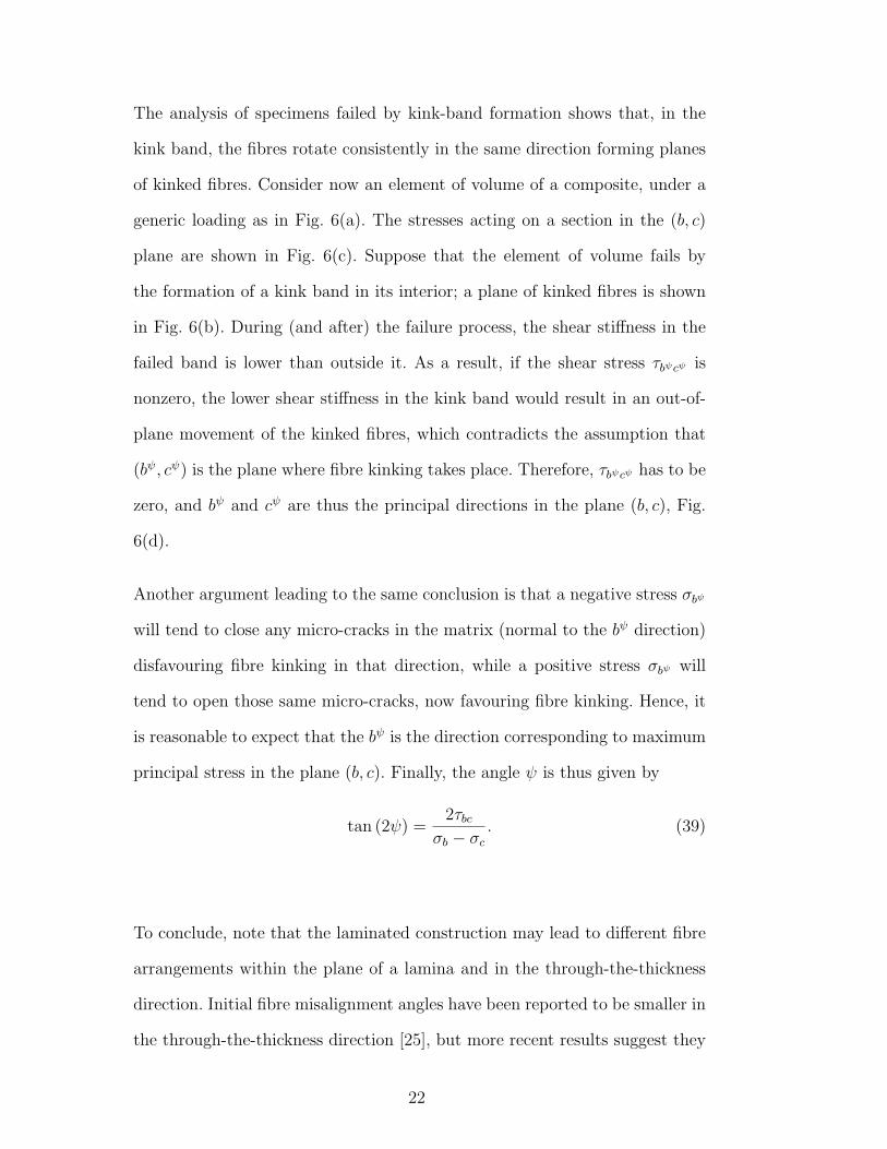
The analysis of specimens failed by kink-band formation shows that, in the
kink band, the fibres rotate consistently in the same direction forming planes
of kinked fibres. Consider now an element of volume of a composite, under a
generic loading as in Fig. 6(a). The stresses acting on a section in the (b, c)
plane are shown in Fig. 6(c). Suppose that the element of volume fails by
the formation of a kink band in its interior; a plane of kinked fibres is shown
in Fig. 6(b). During (and after) the failure process, the shear stiffness in the
failed band is lower than outside it. As a result, if the shear stress τbψcψ is
nonzero, the lower shear stiffness in the kink band would result in an out-of-
plane movement of the kinked fibres, which contradicts the assumption that
(bψ, cψ) is the plane where fibre kinking takes place. Therefore, τbψcψ has to be
zero, and bψ and cψ are thus the principal directions in the plane (b, c), Fig.
6(d).
Another argument leading to the same conclusion is that a negative stress σbψ
will tend to close any micro-cracks in the matrix (normal to the bψ direction)
disfavouring fibre kinking in that direction, while a positive stress σbψ will
tend to open those same micro-cracks, now favouring fibre kinking. Hence, it
is reasonable to expect that the bψ is the direction corresponding to maximum
principal stress in the plane (b, c). Finally, the angle ψ is thus given by
tan (2ψ) =2τbc
σb − σc
. (39)
To conclude, note that the laminated construction may lead to different fibre
arrangements within the plane of a lamina and in the through-the-thickness
direction. Initial fibre misalignment angles have been reported to be smaller in
the through-the-thickness direction [25], but more recent results suggest they
22
(a) (b )
(c ) (d ) (e ) (f )
b
a
c
�
bψψ� ψ
b
�a
�b
c
θ
c
b
ψ
�σ−
�σ−cbτbcτ
cbτbcτ
�σ−
�σ−ψσ �−
ψσ �−
ψσ �−
ψσ −
b
c
ψ
ψψ� �� ������ ������ ����������! �"# �$��
φ%&
ψc
θ ψb
a
'b
(a
Fig. 6. 3D kinking model
can be similar in magnitude [26]. The present model assumes that the initial
fibre misalignment is equal in magnitude in the transverse direction, through
the thickness direction, or in any direction between the two. In order to apply
this model, the only material properties that need to be known, in addition
to the in-plane shear response, are Yc, SL, φo, Yt and Xc. All the remaining
parameters follow from these.
6 Applications
6.1 Failure envelope (σb, τab)
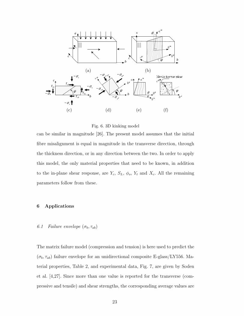
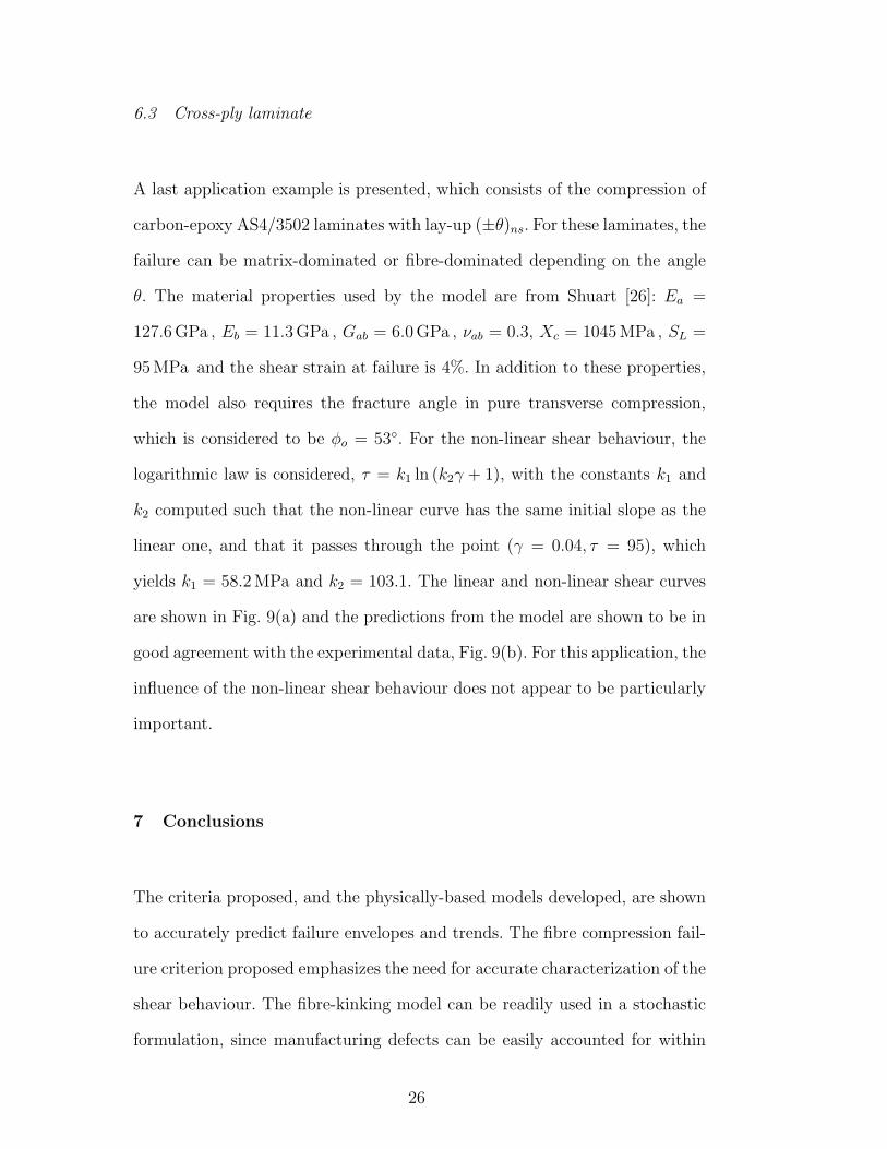
The matrix failure model (compression and tension) is here used to predict the
(σb, τab) failure envelope for an unidirectional composite E-glass/LY556. Ma-
terial properties, Table 2, and experimental data, Fig. 7, are given by Soden
et al. [4,27]. Since more than one value is reported for the transverse (com-
pressive and tensile) and shear strengths, the corresponding average values are
23
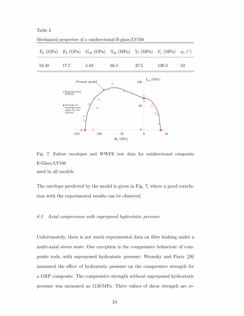
Table 2
Mechanical properties of a unidirectional E-glass/LY556
Ea (GPa) Eb (GPa) Gab (GPa) Sab (MPa) Yt (MPa) Yc (MPa) φo (◦)
53.48 17.7 5.83 66.5 37.5 130.3 53
0
5 0
1 00
- 1 5 0 - 1 00 - 5 0 0 5 0
σb ( M P a )
τ a b ( M P a )
Experimental,W W F E
A v erag e o fexperimental,inpu t f o r th ec riteria
P r e s e n t m o d e l
Fig. 7. Failure envelopes and WWFE test data for unidirectional composite
E-Glass/LY556
used in all models.
The envelope predicted by the model is given in Fig. 7, where a good correla-
tion with the experimental results can be observed.
6.2 Axial compression with superposed hydrostatic pressure
Unfortunately, there is not much experimental data on fibre kinking under a
multi-axial stress state. One exception is the compressive behaviour of com-
posite rods, with superposed hydrostatic pressure. Wronsky and Parry [28]
measured the effect of hydrostatic pressure on the compressive strength for
a GRP composite. The compressive strength without superposed hydrostatic
pressure was measured as 1150 MPa. Three values of shear strength are re-
24

(a) (b )
�
� �
� ���
� ��� ��� � ��� � � ��� � � � ��� ���γ �
τ�� � ������� ��� ��� ���
��� ��� � ��� ���
� �����
� � ���
�������
� � ���
� � � � ����� !�� � " � �
# � $&% � �(')'�� *��',+ � �(��-�+/. �0��� ����1� ��� ��� $2� 3 �4��5� ��� � ��� ��� $2��3 �4�687�% � � � $ �4��+ � �
95:�3 � � ',+ � +�� ; % � �(''< � � � ����� �
� =>� � ��'? : � � 3� ���)� :A@ �4B�C � �
Fig. 8. (a) linear and nonlinear shear curves considered; (b) compressive strength
as a function of the hydrostatic pressure
ported, depending on the test method and specimen dimensions, 42, 48 and
59 MPa. The biggest value of the three is used herein, for being (arguably)
more representative.
These material properties are not enough to completely define the material for
the purposes of the failure model. Therefore, some material properties have
been assumed from typical values as follows: (i) the shear modulus is taken as
6600 MPa, (ii) the fracture angle in matrix compression is φo = 53◦, (iii) the
transverse compressive strength is taken as 140 MPa. To analyse the effect of
shear nonlinearity, a logarithmic law is considered, τ = k1 ln (k2γ + 1), with
k1 = 200 MPa and k2 = 33, which yields the same initial shear modulus. The
linear and nonlinear curves are compared in Fig. 8(a).
The effect of the hydrostatic pressure on the compressive strength, as predicted
from the model, is compared with the experimental data from Wronsky and
Parry [28] in Fig. 8(b). The comparison suggests that the physics of the com-
pressive behaviour may have been correctly represented in the model, but
clearly, experimental measurements of the assumed material properties are
required for a rigorous validation of the model.
25
6.3 Cross-ply laminate
A last application example is presented, which consists of the compression of
carbon-epoxy AS4/3502 laminates with lay-up (±θ)ns. For these laminates, the
failure can be matrix-dominated or fibre-dominated depending on the angle
θ. The material properties used by the model are from Shuart [26]: Ea =
127.6 GPa , Eb = 11.3 GPa , Gab = 6.0 GPa , νab = 0.3, Xc = 1045 MPa , SL =
95 MPa and the shear strain at failure is 4%. In addition to these properties,
the model also requires the fracture angle in pure transverse compression,
which is considered to be φo = 53◦. For the non-linear shear behaviour, the
logarithmic law is considered, τ = k1 ln (k2γ + 1), with the constants k1 and
k2 computed such that the non-linear curve has the same initial slope as the
linear one, and that it passes through the point (γ = 0.04, τ = 95), which
yields k1 = 58.2 MPa and k2 = 103.1. The linear and non-linear shear curves
are shown in Fig. 9(a) and the predictions from the model are shown to be in
good agreement with the experimental data, Fig. 9(b). For this application, the
influence of the non-linear shear behaviour does not appear to be particularly
important.
7 Conclusions
The criteria proposed, and the physically-based models developed, are shown
to accurately predict failure envelopes and trends. The fibre compression fail-
ure criterion proposed emphasizes the need for accurate characterization of the
shear behaviour. The fibre-kinking model can be readily used in a stochastic
formulation, since manufacturing defects can be easily accounted for within
26

(a) (b )
�
� �
� ���
� ��� � � ��� ��� ��� �� ��� ��γ � �
τ� �������������� ��� ���
� ����! � ��� ���
"
#�"�"
$�"�"
%�&�"�"
" %'" &�" (�" #�" )�" *�" +�" $�" ,�"-�.�/10 23.�450 6�27.�298�: ;=<° >
?A@5;CB5;'234D/=6�EF;':G<�: 0 23;H.�@ >?A@5;CB5;'234D/=6�EF;':G<�2F6�29IJ: 0 29;�.�@ >KALFMF;H@50 /=;H294N.�:G<JO�P9Q3.�@54HRS%H,�$�, >
T 6�/=M3@ ;HB5B 0 UF;VB54 @5;'238�4 PW<JXY?G. >
Fig. 9. (a) Linear and non-linear shear curves; (b) comparison of the results from
the present model to the experimental results from Shuart [26]
the model.
The application of these criteria to more complex structures requires the use
of numerical methods. An implementation of these criteria in FE is described
in the second paper of this series [12].
Acknowledgements
The funding of this research from the Portuguese Foundation for Science and
Technology is greatfully acknowledged.
References
[1] M. J. Hinton, P. G. Soden, A comparison of the predictive capabilities of current
failure theories for composite laminates, judged against experimental evidence,
Composites Science and Technology 62 (2002) 1725–1797.
[2] Z. Hashin, A. Rotem, A fatigue failure criterion for fibre reinforced materials,
27
Journal of Composite Materials 7 (1973) 448–464.
[3] Z. Hashin, Failure criteria for unidirectional fibre composites, Journal of Applied
Mechanics 47 (1980) 329–334.
[4] P. D. Soden, M. J. Hinton, A. S. Kaddour, Biaxial test results for
strength and deformation of a range of e-glass and carbon fibre reinforced
composite laminates: Failure exercise benchmark data, Composites Science and
Technology 62 (2002) 1489–1514.
[5] A. Puck, Calculating the strength of glass fibre/plastic laminates under
combined load, Kunststoffe, German Plastics 55 (1969) 18–19, original in
German.
[6] A. Puck, W. Schneider, On failure mechanisms and failure criteria of filament-
wound glass-fibre/resin composites, Plastics and Polymers (1969) 33–44Original
in German.
[7] A. Puck, H. Schurmann, Failure analysis of FRP laminates by means of
physically based phenomenological models, Composites Science and Technology
58 (1998) 1045–1067.
[8] A. Puck, H. Schurmann, Failure analysis of FRP laminates by means of
physically based phenomenological models, Composites Science and Technology
62 (2002) 1633–1662.
[9] C. G. Davila, N. Jaunky, S. Goswami, Failure criteria for FRP laminates in
plane stress, in: 44th AIAA/ ASME/ ASCE/ AHS/ ASC Structures, Structural
Dynamics, and Materials Conference, 2003, AIAA Paper 2003-1991.
[10] C. G. Davila, P. P. Camanho, Failure criteria for FRP laminates in plane
stress, Tech. Rep. NASA/TM-2003-212663, National Aeronautics and Space
Administration, U. S. A. (2003).
28
[11] S. T. Pinho, L. Iannucci, P. Robinson, Physically-based failure models
and criteria for laminated fibre-reinforced composites. Development and
Implementation, Tech. Rep. 04-02, Imperial College London, Department of
Aeronautics (2004).
[12] S. T. Pinho, L. Iannucci, P. Robinson, Physically-based failure models and
criteria for laminated fibre-reinforced composites. Part II: FE implementation,
Submitted to Composites: Part A.
[13] Livermore Software Technology Corporation, California, USA, LS-Dyna 970
(2003).
[14] A. Puck, Failure analysis for FRP. Models for use in practice, Hanser, Munich,
Viena. Original in German (1996).
[15] C. T. Sun, B. J. Quinn, D. W. Oplinger, Comparative evaluation of failure
analysis methods for composite laminates, DOT/FAA/AR (1996) 95–109.
[16] C. R. Schultheisz, A. M. Waas, Compressive failure of composites, part I:
Testing and micromechanical theories, Progress in Aerospace Sciences 32 (1996)
1–42.
[17] V. W. Rosen, Mechanics of composite strengthening, Fiber Composite Materials
American Society of Metals, Metals Park, Ohio (1965) 37–75.
[18] A. S. Argon, Fracture of composites, in: Treatise on Materials Science and
Technology, Academic Press, New York, 1972, pp. 79–114.
[19] B. Budiansky, Micromechanics, Computers and Structures 16 (1983) 3–12.
[20] B. Budiansky, N. A. Fleck, Compressive failure of fibre composites, Journal of
the Mechanics and Physics of Solids 41 (1) (1993) 183–211.
[21] B. Budiansky, N. A. Fleck, J. C. Amazigo, On kink-band propagation in fiber
29
composites, Journal of the mechanics and physics of solids 46 (9) (1998) 1637–
1653.
[22] S. Kyriakides, R. Arseculeratne, E. J. Perry, On the compressive failure of fiber
reinforced composites, International Journal of Solids and Structures 32 (6/7)
(1995) 689–738.
[23] T. J. Vogler, S. Kyriakides, Initiation and axial propagation of kink bands in
fiber composites, Acta Materialia 45 (6) (1997) 2443–2454.
[24] T. J. Vogler, S. Kyriakides, On the axial propagation of kink bands in fiber
composites: Part i experiments, International Journal of Solids and Structures
36 (1999) 557–574.
[25] J. G. Davis Jr, Compressive strength of fiber-reinforced composite materials,
in: Composite Reliability, ASTM STP 580, Americal Society for Testing and
Materials, Philadelphia, 1975, pp. 364–377.
[26] M. J. Shuart, Failure of compression-loaded multidirectional composite
laminates, AIAA Journal 27 (1989) 1274–1279.
[27] P. D. Soden, M. J. Hinton, A. S. Kaddour, Lamina properties, lay-up
configurations and loading conditions for a range of fibre-reinforced composite
laminates, Composites Science and Technology 58 (1998) 1011–1022.
[28] A. S. Wronsky, T. V. Parry, Compressive failure and kinking in uniaxially
aligned glass-resin composite under superposed hydrostatic pressure, Journal
of Materials Science 17 (1982) 3656–3662.
30