physics-04 (leph 201502) 1. details of module and its
TRANSCRIPT

Physics 2019 Physics-04 (Leph_201502) Electronic Device
Physics-04 (Leph_201502)
1. Details of Module and its structure
Module Detail
Subject Name Physics
Course Name Physics 04 (Physics Part-2, Class XII)
Module Name/Title Unit-10, Module-02: Propagation of electromagnetic wave
Chapter-15: Communication systems
Module Id leph_201502_eContent
Pre-requisites Brief history of electronic communication Frequency, bandwidth,
signal, modulation, attenuation
Objectives After going through this module student will be able to:
Understand the mode of propagation of electromagnetic
waves
Ground wave propagation
Sky wave propagation
Space wave propagation
Satellite communication
Keywords Frequency, attenuation, antenna, total internal reflection,
bandwidth, transmitter and receiver, propagation of
electromagnetic waves, ground waves, sky waves, space waves,
satellite communication
2. Development Team
Role Name Affiliation
National MOOC
Coordinator (NMC)
Prof. Amarender P. Behera Central Institute of Educational
Technology, NCERT, New Delhi
Programme Coordinator Dr. Mohd Mamur Ali Central Institute of Educational
Technology, NCERT, New Delhi
Course Coordinator /
(PI)
Anuradha Mathur Central Institute of Educational
Technology, NCERT, New Delhi
Subject Matter Expert
(SME)
Dinesh Tyagi Army Public School
Hindon
Review Team Prof. V. B. Bhatia (Retd.)
Associate Prof. N.K. Sehgal
(Retd.)
Prof. B.K. Sharma (Retd.)
Delhi University
Delhi University
DESM, NCERT, New Delhi

Physics 2019 Physics-04 (Leph_201502) Electronic Device
Physics-04 (Leph_201502)
TABLE OF CONTENTS:
1. Unit syllabus
2. Module wise distribution of unit syllabus
3. Words you must know
4. Introduction
5. Influence of atmosphere of earth
6. Propagation of electromagnetic waves
7. Satellite communication
8. Indian satellite program
9. Summary
1. UNIT SYLLABUS
Unit 10: Communication Systems
Chapter 15: Communication Systems
Elements of a communication system (block diagram) bandwidth of signals speech, TV and
digital data) bandwidth of transmission medium, propagation of electromagnetic waves in the
atmosphere, sky and space wave propagation , satellite communication, need for modulation,
types of modulation, amplitude modulation, production of amplitude modulated wave,
detection of amplitude modulated wave, Internet and mobile phones
2. MODULE WISE DISTRIBUTION OF UNIT SYLLABUS 6 MODULES
Module 1
History of communication
Special vocabulary
Signals and bandwidth
Module 2
Propagation of electromagnetic wave
Ground wave
Sky wave
Space wave
Satellite communication
Module 3
Modulation
Need for modulation
Types of modulation
Amplitude modulation AM
Frequency modulation FM
Physics 2019 Physics-04 (Leph_201502) Electronic Device
Physics-04 (Leph_201502)
Meaning of tuner frequencies 98.3FM
Module 4
Amplitude modulation
Modulation index
Production of amplitude modulated wave
Detection of amplitude modulated wave
Applications of amplitude modulation
Module 5
Short range communications
Increasing the area of influence using antenna
Use in factories, villages, towns for police work
Internet
Internet servers
Module 6
Mobile phones
Mobile towers
3G,4G,5G
Mobile companies, what do they do?
MODULE 2
3. WORDS YOU MUST KNOW
Communication: The process of putting across ideas through words and pictures
Audio communication: Communication by means of speech/sound or messages that can be
received by our ears
Video communication- Communication by means of pictures, still or moving or messages
that can be received by our eyes
Audio video communication- Communication by means of speech/sound or messages that
can be received by our ears
Device- an apparatus designed for special functions
Mode of transfer of information- method of transfer of information
Antenna- a device designed to send out and receive electromagnetic waves.
Electromagnetic waves-
Physics 2019 Physics-04 (Leph_201502) Electronic Device
Physics-04 (Leph_201502)
The range of electromagnetic signals encompassing all frequencies is referred to as the
electromagnetic spectrum
Frequency: It is defined as number of cycles per second or number of waves per second.
Wavelength is the distance occupied by one cycle of a wave and is usually expressed in
meters. Wavelength is also the distance traveled by an electromagnetic wave during the time
of one cycle. The wavelength of a signal is represented by the Greek letter lambda (λ).
Transducer: An electrical transducer may be defined as a device that converts some physical
variable (pressure, displacement, force, temperature, etc.) into corresponding variations in the
electrical signal at its output. For example, a microphone converts sound energy into
electrical energy.
Signal: Information converted in electrical form and suitable for transmission is called
a signal. Signals can be either analog or digital.
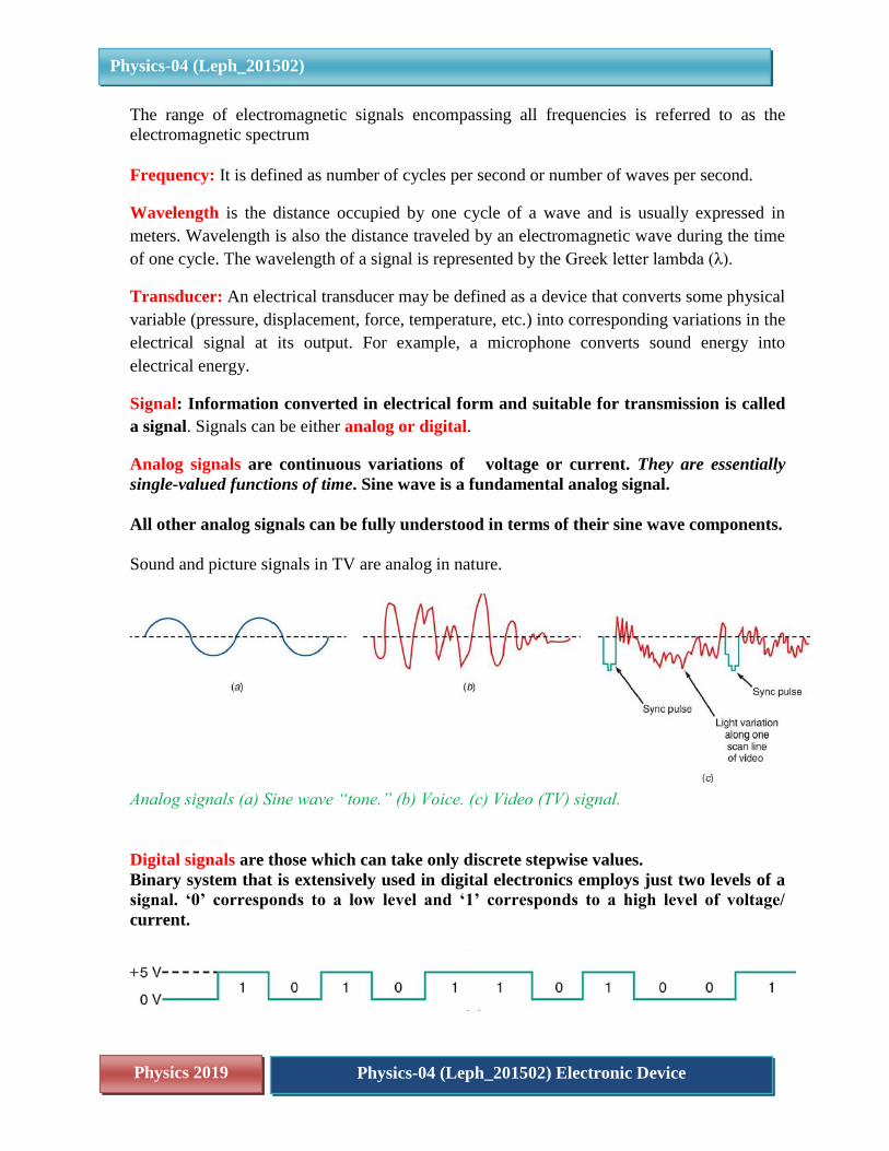
Analog signals are continuous variations of voltage or current. They are essentially
single-valued functions of time. Sine wave is a fundamental analog signal.
All other analog signals can be fully understood in terms of their sine wave components.
Sound and picture signals in TV are analog in nature.
Analog signals (a) Sine wave “tone.” (b) Voice. (c) Video (TV) signal.
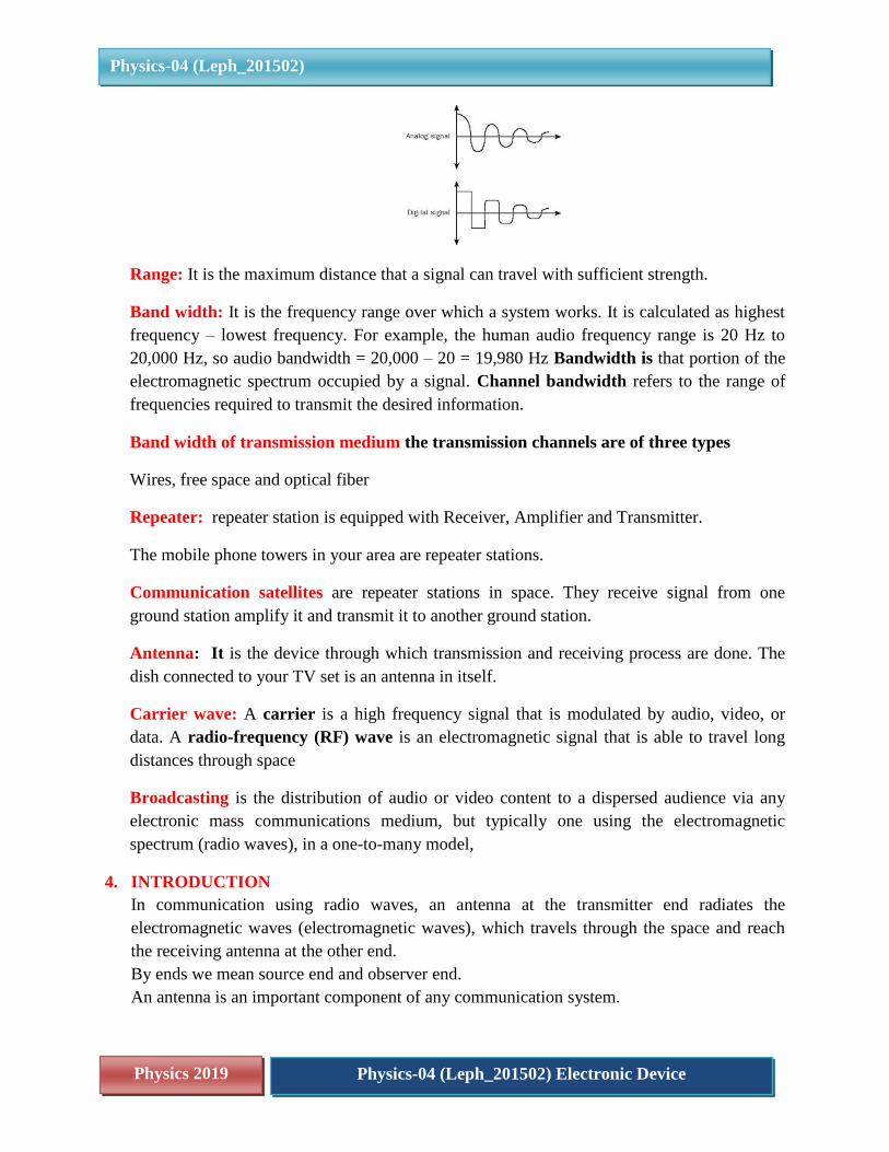
Digital signals are those which can take only discrete stepwise values.
Binary system that is extensively used in digital electronics employs just two levels of a
signal. ‘0’ corresponds to a low level and ‘1’ corresponds to a high level of voltage/
current.

Physics 2019 Physics-04 (Leph_201502) Electronic Device
Physics-04 (Leph_201502)
Digital signals (a) Telegraph (Morse code). (b) Continuous-wave (CW) code. (c) Serial
binary code
Technically speaking, a signal is a wave, amplitude or frequency of which varies with
time and the signal can be analog or digital.
NOISE: These are unwanted signals having same or similar frequency as that of required
signal. They distort the transmission and receiving process. A virus in a computer is example
of noise. A virus is an unwanted program in the same language in which your required
program is, it disrupts your program.
Communication channel: The communication channel is the medium by which the
electronic signal is sent from one place to another. Types of media include electrical
conductors, Optical media, Free space, and System-specific media (e.g., water is the medium
for sonar).
Transmitter: It is the device that converts the information (message) into a form suitable for
transmission. In above example the online shopping company is the transmitter.
Receiver: It is the device that retrieves the information from received signal. In shopping
example, you are the receiver. A receiver is a collection of electronic components and
circuits that accepts the transmitted message from the channel and converts it back into a
form understandable by humans. Receivers contain amplifiers, oscillators, mixers, tuned
circuits and filters, and a detector that recovers the original intelligence signal from the
modulated carrier
Transceivers: A transceiver is an electronic unit that incorporates circuits that both send
and receive signals. Examples are: Telephones, Fax machines, radios, Cell, mobile phones,
computers.
Amplification: It is the process of increasing the strength of signal. Amplification
compensates for attenuation. Amplification is done by electronic circuit.
Attenuation: It refers to loss in strength of signal while propagating from transmitter to
receiver Signal attenuation, or degradation, exists in all media of wireless transmission. It is
usually proportional to the square of the distance between the transmitter and receiver
Physics 2019 Physics-04 (Leph_201502) Electronic Device
Physics-04 (Leph_201502)
Range: It is the maximum distance that a signal can travel with sufficient strength.
Band width: It is the frequency range over which a system works. It is calculated as highest
frequency – lowest frequency. For example, the human audio frequency range is 20 Hz to
20,000 Hz, so audio bandwidth = 20,000 – 20 = 19,980 Hz Bandwidth is that portion of the
electromagnetic spectrum occupied by a signal. Channel bandwidth refers to the range of
frequencies required to transmit the desired information.
Band width of transmission medium the transmission channels are of three types
Wires, free space and optical fiber
Repeater: repeater station is equipped with Receiver, Amplifier and Transmitter.
The mobile phone towers in your area are repeater stations.
Communication satellites are repeater stations in space. They receive signal from one
ground station amplify it and transmit it to another ground station.
Antenna: It is the device through which transmission and receiving process are done. The
dish connected to your TV set is an antenna in itself.
Carrier wave: A carrier is a high frequency signal that is modulated by audio, video, or
data. A radio-frequency (RF) wave is an electromagnetic signal that is able to travel long
distances through space
Broadcasting is the distribution of audio or video content to a dispersed audience via any
electronic mass communications medium, but typically one using the electromagnetic
spectrum (radio waves), in a one-to-many model,
4. INTRODUCTION
In communication using radio waves, an antenna at the transmitter end radiates the
electromagnetic waves (electromagnetic waves), which travels through the space and reach
the receiving antenna at the other end.
By ends we mean source end and observer end.
An antenna is an important component of any communication system.
Physics 2019 Physics-04 (Leph_201502) Electronic Device
Physics-04 (Leph_201502)
It is employed at both the transmitting as well as receiving end; the transmitter radiates
electromagnetic waves into the free space. While at the receiving end the antenna picks up
the transmitted signal.
Audio video and data signals are too low in intensity and cannot travel long distances. The
electrical signal cannot be transmitted directly; it has to be modulated. So they are coupled
with high frequency electromagnetic waves (radio waves) with the help of transducers. The
process as we have said, is called modulation
An antenna basically is a length of conductor and acts as a conversion device. The electrical
energy is converted into electromagnetic waves. At the receiving end it does exactly the
reverse. The length of the antenna should be such that it acts as a resonant circuit at the
frequency. Generally, its length is λ/2, where λ is the wavelength of the radio frequency
(carrier wave) applied.
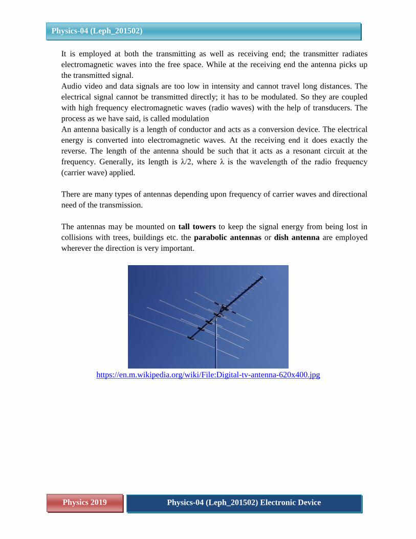
There are many types of antennas depending upon frequency of carrier waves and directional
need of the transmission.
The antennas may be mounted on tall towers to keep the signal energy from being lost in
collisions with trees, buildings etc. the parabolic antennas or dish antenna are employed
wherever the direction is very important.
https://en.m.wikipedia.org/wiki/File:Digital-tv-antenna-620x400.jpg

Physics 2019 Physics-04 (Leph_201502) Electronic Device
Physics-04 (Leph_201502)
https://upload.wikimedia.org/wikipedia/commons/4/40/Erdfunkstelle_Raisting_2.jpg
In order to estimate the size of the required antenna
Let us calculate the length of a dipole antenna for transmission of 300 MHz
f = 300 × 106 Hz
𝜆 =velocity of em wave
frequency of em wave=
3 × 10⁸𝑚/𝑠
3 × 10⁸𝐻𝑧= 1𝑚
Hence size of antenna is 0.5 m
It can be easily seen that the size of the antenna decreases with increases with frequency
of the carrier wave
As the EM waves travel away from the transmitter, the strength of wave keeps on decreasing
(called attenuation). In this module let us study the role of atmosphere in propagation of
electromagnetic signal waves.
We will now consider propagation of electromagnetic waves in atmosphere

Physics 2019 Physics-04 (Leph_201502) Electronic Device
Physics-04 (Leph_201502)
5. INFLUENCE OF ATOMOSPHERE OF THE EARTH
The atmosphere surrounding the earth is complex; its composition and density vary
with altitude and seasonal conditions.
Several factors influence the propagation of EM wave and the path they follow.
At this point it is important to mention that earth’s atmosphere also plays a vital role in
propagation of EM waves (recall that during clouds or rain your TV signals gets disrupted).
In order to understand the effect, let us first consider the different layers of the atmosphere
https://upload.wikimedia.org/wikipedia/commons/3/36/Atmosphere_layers.jpgA
As you can see our atmosphere has layers, depending upon the distance from the surface of the
earth of course there is no clear boundaries. it extends up to 350 km
These layers are-

Physics 2019 Physics-04 (Leph_201502) Electronic Device
Physics-04 (Leph_201502)
Troposphere
Stratosphere
Mesosphere
Thermosphere
The temperature, density and composition of the layers changes as we go away from the surface
of the earth. The composition of different layers in the atmosphere is not the same. Water vapor
for example, is confined to the lowest layer whereas ozone is in the layers 50-80 km above the
surface of the earth. The ionosphere extends from about 60-350 km, plays an important role in
communication. It is subdivided into layers as C, D, E, F1 and F2
Read this table to recognize some everyday terms like AM – FM as in AM, FM radio, radio
mirchi.
The values given are only to familiarize you with the wavelengths, some special names and
the main applications
Frequency
band
name Wavelength
range
Analog data Digital data
Data rate
Main
application Modulation bandwidth
30-300 kHz LF 1-10km 0.1-100bps navigation
300-3000kHz MF 100m-1m AM Upto 4
kHz
10-1000bps Commercial
AM radio
3-30MHz HF 10-100m AM Upto4kHz 10-3000bps radio
30-300MHz VHF 1-10m AM,FM 5kHz-
5MHz
To 100kbps VHFTV
FM radio
300-
3000MHz
UHF 10cm--1m AM-FM Upto 20
MHz
10Mbps HD TV
terrestrial
microwave
3-30 GHz
30-300GHz
SHF-
EHF
1-10cm
1mm-1cm
FM Upto
500MHz
100Mbps Terrestrial
microwave
satellite
microwave
,mobile
phones
internet
OR
Physics 2019 Physics-04 (Leph_201502) Electronic Device
Physics-04 (Leph_201502)
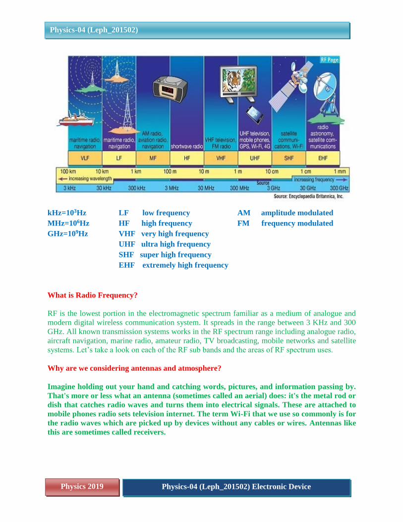
kHz=103Hz LF low frequency AM amplitude modulated
MHz=106Hz HF high frequency FM frequency modulated
GHz=109Hz VHF very high frequency
UHF ultra high frequency
SHF super high frequency
EHF extremely high frequency
What is Radio Frequency?
RF is the lowest portion in the electromagnetic spectrum familiar as a medium of analogue and
modern digital wireless communication system. It spreads in the range between 3 KHz and 300
GHz. All known transmission systems works in the RF spectrum range including analogue radio,
aircraft navigation, marine radio, amateur radio, TV broadcasting, mobile networks and satellite
systems. Let’s take a look on each of the RF sub bands and the areas of RF spectrum uses.
Why are we considering antennas and atmosphere?
Imagine holding out your hand and catching words, pictures, and information passing by.
That's more or less what an antenna (sometimes called an aerial) does: it's the metal rod or
dish that catches radio waves and turns them into electrical signals. These are attached to
mobile phones radio sets television internet. The term Wi-Fi that we use so commonly is for
the radio waves which are picked up by devices without any cables or wires. Antennas like
this are sometimes called receivers.
Physics 2019 Physics-04 (Leph_201502) Electronic Device
Physics-04 (Leph_201502)
A transmitter is a different kind of antenna that does the opposite job to a receiver: it turns
electrical signals into radio waves so they can travel sometimes thousands of kilometers
around the Earth or even into space and back.
Antennas and transmitters are the key to virtually all forms of modern telecommunication.
Let's take a closer look at what they are and how they work!
The atmosphere is transparent to visible radiations since we see the sun and stars through this
however the atmosphere absorbs most infrared radiation. The ozone layer is found to block UV
radiations. This information should help us realize that the atmosphere must be behaving
differently towards radio waves as well.
The behaviour of waves of wavelength 103m and higher is of interest in communication systems
The table gives the activity of different band widths in the different layers of the atmosphere.
Different layers of atmosphere and their interaction with the propagating electromagnetic
waves
The choice of carrier wave frequency depends on the nature of the signal to be transmitted.
To say it easily
Role of atmosphere on propagation of electromagnetic (em or EM) waves:
(i) Earth’s atmosphere allows em waves of visible range to pass through it that is why
sunlight reaches the earth.
(ii) The atmosphere’s ozone layer blocks UV radiations.
(iii) The clouds block infra-red radiations, that is why it is warmer on cloudy days and night.
(iv) EM waves up to 40 MHz are reflected back by different layers of ionosphere.
(v) EM waves above 40MHz penetrate through the ionosphere and travel in a straight line.
These are used in satellite communication.
(vi) EM waves of few KHz to 3MHz glides near the earth surface.
6. PROPAGATION OF ELECTROMAGNETIC WAVE
In a communication set up EM waves travel in three modes:
Ground wave propagation
Sky wave propagation and
Space wave propagation.

Physics 2019 Physics-04 (Leph_201502) Electronic Device
Physics-04 (Leph_201502)
Various propagation modes for electromagnetic waves
Let us discuss each one of these in some detail. The idea here is not to go into technical details
but get a general idea of how em waves would travel in atmosphere.
In wireless communication a signal is emitted from a transmitter antenna and received by another
antenna at the receiver. An electromagnetic wave after being radiated by the transmitting antenna
may be divided into various parts.one part travels along the surface and is called surface or
ground wave. The remainder moves upwards towards the sky and space and is called sky waves
and space waves.
a) GROUND WAVE PROPAGATION OF EM WAVE
Ground wave or surface wave propagation is a mode of propagation in which the wave
moves close to earth’s surface. These waves travel parallel or at lower angles with the
earth’s surface after they are radiated from a transmitting antenna. As ground wave passes
over the surface of the earth, its energy is absorbed by earth’s atmosphere. The energy
decreases and the signal die down. The absorption there fore does not allow the wave to
propagate and sustain its amplitude over large distances from the transmitting antenna.
It is suitable for low frequencies few KHz to 3MHz.
The mode of propagation is called surface wave propagation and the wave glides over the
surface of the earth.
Physics 2019 Physics-04 (Leph_201502) Electronic Device
Physics-04 (Leph_201502)
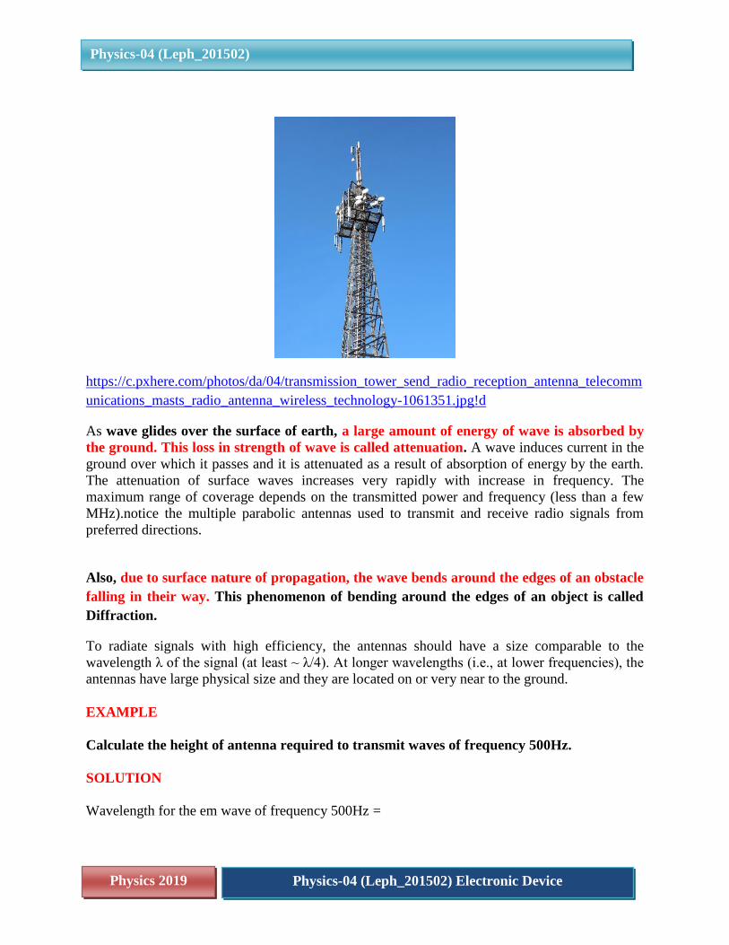
https://c.pxhere.com/photos/da/04/transmission_tower_send_radio_reception_antenna_telecomm
unications_masts_radio_antenna_wireless_technology-1061351.jpg!d
As wave glides over the surface of earth, a large amount of energy of wave is absorbed by
the ground. This loss in strength of wave is called attenuation. A wave induces current in the
ground over which it passes and it is attenuated as a result of absorption of energy by the earth.
The attenuation of surface waves increases very rapidly with increase in frequency. The
maximum range of coverage depends on the transmitted power and frequency (less than a few
MHz).notice the multiple parabolic antennas used to transmit and receive radio signals from
preferred directions.
Also, due to surface nature of propagation, the wave bends around the edges of an obstacle
falling in their way. This phenomenon of bending around the edges of an object is called
Diffraction.
To radiate signals with high efficiency, the antennas should have a size comparable to the
wavelength λ of the signal (at least ~ λ/4). At longer wavelengths (i.e., at lower frequencies), the
antennas have large physical size and they are located on or very near to the ground.
EXAMPLE
Calculate the height of antenna required to transmit waves of frequency 500Hz.
SOLUTION
Wavelength for the em wave of frequency 500Hz =

Physics 2019 Physics-04 (Leph_201502) Electronic Device
Physics-04 (Leph_201502)
𝑣𝑒𝑙𝑜𝑐𝑖𝑡𝑦
𝑓𝑟𝑒𝑞𝑢𝑒𝑛𝑐𝑦=
3 𝑥105𝑘𝑚/𝑠
500𝐻𝑧= 6 𝑥102𝑘𝑚
Size of antenna will be
𝜆
4=
600
4= 150 𝑘𝑚
This is practically impossible!!
EXAMPLE
A TV antenna is of height ‘h’ estimating the covering range of the antenna. Take radius of
the earth as R.
SOLUTION
TV signals are high frequency signals; they are not reflected back by the atmosphere.
Consider
AB be a tower of height h and
R, radius of earth
If broadcast is made from the top B of tower (AB), no reception of direct signals is possible
beyond points C and D as shown in the figure.
The distance up to which signals can be received AC=AD is limited due to the curvature of the
earth and is called the range of the antenna.
Let this be the range = d
The signals may be received in the region CAD
Let us relate d to h and R
Physics 2019 Physics-04 (Leph_201502) Electronic Device
Physics-04 (Leph_201502)
In right angled triangle BOD
∠𝐵𝐷𝑂 = 900
𝐵𝑂2 = (𝑂𝐷)2 + (𝐵𝐷)2
(𝑅 + ℎ)2 = (𝑅)2 + (𝐵𝐷)2
As height h of the antenna tower is very small as compared to radius R of the earth, hence point
S will be close to A or we can say
𝐵𝐷~𝐴𝐷 = 𝑑 (𝑅 + ℎ)2 = (𝑅)2 + (𝑑)2
𝑑2 = (𝑅 + ℎ)2 − (𝑅)2 = 2𝑅ℎ + ℎ2
Now since h <<R hence ℎ2 ≪ 2𝑅ℎ
𝑑2 ⋍ 2𝑅ℎ
Height of transmitting antenna
𝐡 =𝐝𝟐
𝟐𝐑
Covering range of the TV antenna is
𝐝 = √𝟐𝐑𝐡
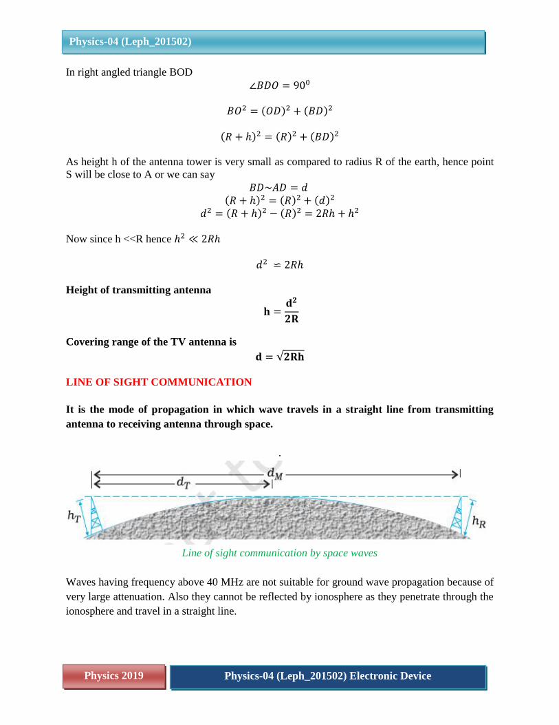
LINE OF SIGHT COMMUNICATION
It is the mode of propagation in which wave travels in a straight line from transmitting
antenna to receiving antenna through space.
.
Line of sight communication by space waves
Waves having frequency above 40 MHz are not suitable for ground wave propagation because of
very large attenuation. Also they cannot be reflected by ionosphere as they penetrate through the
ionosphere and travel in a straight line.

Physics 2019 Physics-04 (Leph_201502) Electronic Device
Physics-04 (Leph_201502)
Sky waves travels in a straight line from transmitting antenna to the receiving antenna. Sky
waves are used for line-of-sight (LOS) communication as well as satellite communication.
At frequencies above 40 MHz, communication is essentially limited to line-of-sight paths.
At these frequencies, the antennas are relatively smaller and can be placed at heights of many
wavelengths above the ground. Because of line-of-sight nature of propagation, direct waves get
blocked at some point by the curvature of the earth as illustrated in Fig
Television tower of Doordarshan Kendra, Chennai
Since the waves travel in a straight line from transmitting antenna to receiving antenna, these sky
waves are used for line of sight (LOS) communication.
Space and sky waves are also used for television broadcast, microwave link, cell phones
and satellite communication.
What is the advantage of high antennas?
dM = maximum line of sight distance between transmitting antenna and receiving antenna.

Physics 2019 Physics-04 (Leph_201502) Electronic Device
Physics-04 (Leph_201502)
dT = radio horizon of transmitting antenna (it is the radius up to which the transmitting antenna
can send the signal)
dR = radio horizon of receiving antenna (it is the radius up to which the receiving antenna can
pick the signal)
hT = height of transmitting antenna
hR = height of receiving antenna
R = radius of earth = 6.4 x 10⁶ m
𝑑𝑀 = 𝑑𝑇 + 𝑑𝑅
dM = √𝟐𝐑 hT + √𝟐𝐑 hR
Note :
Signal transfer from transmitting antenna to receiving antenna is like a relay race. The
transmitter sends signal up to vicinity of receiving antenna from there the receiving antenna
picks the signal. So, range of communication depends not only on the strength of transmitter but
also on strength of receiver.
Radio horizon means the radius up to which the transmitting antenna can send the signal
EXAMPLE
The TV transmission tower in Delhi has a height of 240 m. Calculate the distance up to
which the broadcast can be received by line of sight communication. take the radius of the
earth to be 6.4 x 10⁶m.
SOLUTION
h=240m
R=6.4 x 10⁶ m
d =√2𝑅ℎ
= √2 × [6.43 × 106] × 240
= 55.4km
Due to attenuation and diffraction, this mode of propagation is suitable for local broadcast
like AM broadcast of medium wave band of frequency range 530KHz to 1710Khz.
Local radio stations with coverage of a few square km.
EXAMPLE:

Physics 2019 Physics-04 (Leph_201502) Electronic Device
Physics-04 (Leph_201502)
A transmitting antenna at the top of a tower has a height of 32m. Find the no. of people
receiving the transmission if population density is 10,000 people per sq.km.
Given radius of earth R = 6.4 x 10⁶ m and √𝟏𝟎 = π
SOLUTION:
Range of transmitting antenna (radio horizon of transmitting antenna)
dT = √2𝑅 hT
= (2 x 6.4 × 106 × 32)1/2
= 64 x 102 √10
= 64 × 102 × π meter
= 6.4 × π km
Population covered = population density x area covered
= 10,000 × π dT2
= 10,000 × π3 × 6.4 × 6.4
= 100 × 10 × 3.14 × 64 × 64
= 12,861,440 people
EXAMPLE
A TV tower has a height of 150m. How much population the TV broadcast covers if the
average population density around the tower is 1000km-2. Radius of the earth = 6.4 x 10⁶ m
SOLUTION
The radio horizon of the tower is = d =√2Rh
Area of the region covered = πd2 = π × 2Rh = π × 2 × 6.4 × 106 × 150m2
Population covered = 𝟏𝟐. 𝟖𝝅 × 𝟏𝟓𝟎 × 𝟏𝟎𝟎𝟎 = 𝟔𝟎. 𝟑𝟐 𝐥𝐚𝐤𝐡𝐬
EXAMPLE
A transmitting antenna at the top of a tower has a height 32 m and the height of the
receiving antenna is 50 m. What is the maximum distance between them for satisfactory
communication in LOS mode? Given radius of earth 6.4 × 10⁶ m.
Physics 2019 Physics-04 (Leph_201502) Electronic Device
Physics-04 (Leph_201502)
SOLUTION
dm = √2 × 64 × 105 × 32 + √2 × 64 × 105 × 50
= 64 × 102 × √10 + 8 × 10³ × √10
= 144 × 102 × √10 m = 45.5 km
This attenuation increases rapidly with increase in frequency of wave and with increase in
distance. So, high frequencies and long distance transmission are not suitable for this mode
of propagation.
The maximum range of coverage depends upon power of transmitter and frequency used for
a given frequency of wave the range can be increased by increasing power of transmitter.
This mode of communication is used at airports by ground staff, marine staff on the
ship, trade fairs, shopping malls or local melas.
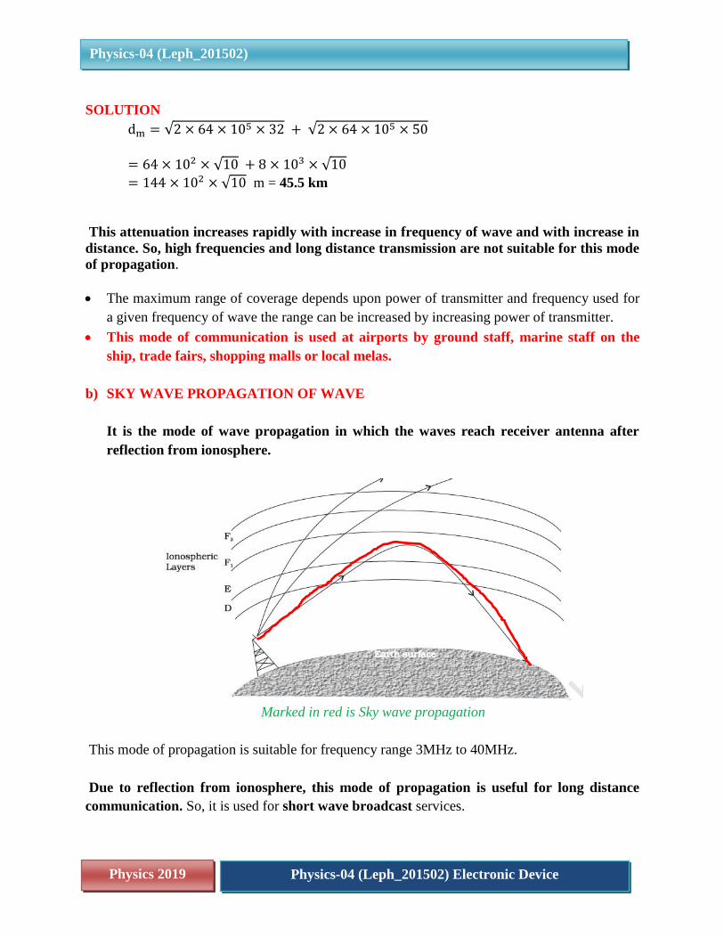
b) SKY WAVE PROPAGATION OF WAVE
It is the mode of wave propagation in which the waves reach receiver antenna after
reflection from ionosphere.
Marked in red is Sky wave propagation
This mode of propagation is suitable for frequency range 3MHz to 40MHz.
Due to reflection from ionosphere, this mode of propagation is useful for long distance
communication. So, it is used for short wave broadcast services.

Physics 2019 Physics-04 (Leph_201502) Electronic Device
Physics-04 (Leph_201502)
The frequency bands employed in space communication is given in the table.
Different frequencies are reflected by different layers of ionosphere.
The maximum frequency that a layer of ionosphere can reflect back is called its Critical
frequency.
Reason for reflection of em waves from the ionosphere.
The ionosphere extends from 65 km to 400 km above earth surface.
Ionizations occur due to absorption of UV and other high energy radiations coming from sun by
air molecules.
The degree of ionization varies with the height. The top layers and bottom layers of ionosphere
have low density of ions. It is because as we go up above the earth’s surface, the density of
atmosphere decreases means there are fewer air molecules as we go up.
In top most layers of ionosphere, the ionizing radiation of sun is quite strong but the air
molecules to be ionized are small in number, hence low density of ions in top most layers.
In bottom most layers, the number of air molecules are quite large but the ionizing radiation of
sun is weak. So, only small number of molecules can be ionized, hence low density of ions in
bottom layers of ionosphere.
The ion density is quite large in the middle of ionosphere.

Physics 2019 Physics-04 (Leph_201502) Electronic Device
Physics-04 (Leph_201502)
The reflection phenomenon from layers of ionosphere is similar to total internal
reflection of light in optics.
c) SPACE WAVE PROPAGATION
For space waves length of antenna is quite small.
Have you ever wondered that your cell phone has no visible antenna? It is because are
operated in Ultra high frequency (UHF) range which extends from 300MHz to
3000MHz.
Due to straight line nature of space waves, these waves are sometimes blocked by earth’s
curvature as shown in fig.
To overcome such problem height of both transmitting antenna and receiving antenna should
be raised.
7. SATELLITE COMMUNICATION
In this mode of communication, the receiver antenna receives signals from transmitting
antenna through satellite.
The transmitter located on earth sends signal to the satellite, this process is called Uplink.
The satellite processes the signal and sends it to receiving station located on earth. This
process of sending the signal to receiving station is called Downlink.
The uplink and downlink frequencies are different.
Uplink frequencies are 5.925 – 6.425 GHz and downlink frequencies are 3.7 – 4.2 GHz. It is
so to avoid Interference between uplink and downlink waves. Interference is a phenomenon
in which there occurs redistribution of energy of two waves meeting at a place.
A communication satellite can be polar or a geo-stationary satellite.

Physics 2019 Physics-04 (Leph_201502) Electronic Device
Physics-04 (Leph_201502)
Indian sub-continent as seen by Mars Orbiter Mission spacecraft during its geocentric phase
A geo-stationary satellite is the one which has same time period as that of earth i.e. 24 hours and
also has the same sense of revolution as that of earth.
This makes satellite stationary with respect to a particular place on earth. Thus the satellite can
easily be located. Now you can understand why your dish of TV, points in a particular direction.
https://hi.m.wikipedia.org/wiki/%E0%A4%9A%E0%A4%BF%E0%A4%A4%E0%A5%8D%E0
%A4%B0:Tata_Sky.JPG
A single satellite cannot cover the whole earth. It is because earth is a sphere.
A satellite can cover only the area falling in front of it, it cannot detect the areas away from its
sight.
Physics 2019 Physics-04 (Leph_201502) Electronic Device
Physics-04 (Leph_201502)
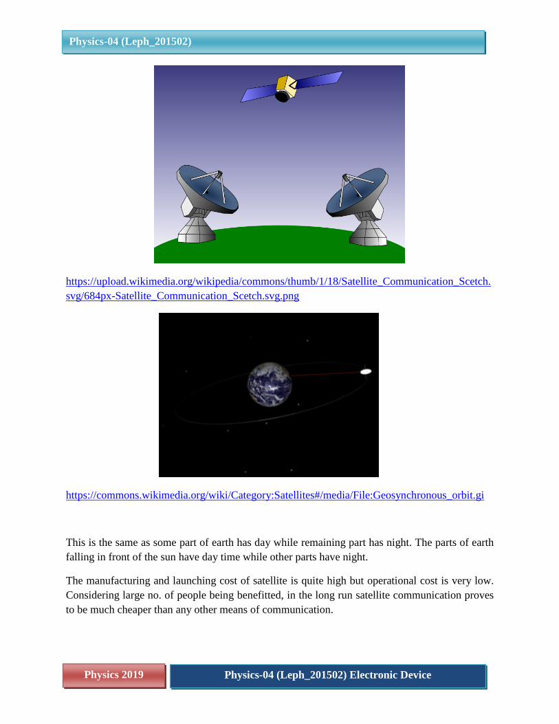
https://upload.wikimedia.org/wikipedia/commons/thumb/1/18/Satellite_Communication_Scetch.
svg/684px-Satellite_Communication_Scetch.svg.png
https://commons.wikimedia.org/wiki/Category:Satellites#/media/File:Geosynchronous_orbit.gi
This is the same as some part of earth has day while remaining part has night. The parts of earth
falling in front of the sun have day time while other parts have night.
The manufacturing and launching cost of satellite is quite high but operational cost is very low.
Considering large no. of people being benefitted, in the long run satellite communication proves
to be much cheaper than any other means of communication.
Physics 2019 Physics-04 (Leph_201502) Electronic Device
Physics-04 (Leph_201502)
The geo-stationary satellites are located 36000 km above equator of earth. Signal has to
travel large distance (2 × 36000 Km) in going and coming back.
This causes a small time delay between transmission and reception of signal.
You must have observed this fact in a live debate on a news channel.
The question asked by reporter is answered after a small time delay by the person present in
the video conference.
8. INDIAN SATELLITE PROGRAM
About ISRO
India decided to go to space when Indian National Committee for Space Research
(INCOSPAR) was set up by the Government of India in 1962. With the visionary
Dr Vikram Sarabhai at its helm, INCOSPAR set up the Thumba Equatorial Rocket
Launching Station (TERLS) in Thiruvananthapuram for upper atmospheric research.
Indian Space Research Organisation, formed in 1969, superseded the erstwhile
INCOSPAR. Vikram Sarabhai, having identified the role and importance of space
technology in a Nation's development, provided ISRO the necessary direction to function as
an agent of development. ISRO then embarked on its mission to provide the Nation space
based services and to develop the technologies to achieve the same independently.
Throughout the years, ISRO has upheld its mission of bringing space to the service of the
common man, to the service of the Nation.
In the process, it has become one of the six largest space agencies in the world. ISRO
maintains one of the largest fleet of communication satellites (INSAT) and remote sensing
(IRS) satellites, that cater to the ever growing demand for fast and reliable communication
and earth observation respectively.
ISRO develops and delivers application specific satellite products and tools to the Nation:
broadcasts,
communications,
weather forecasts,
disaster management tools,
Geographic Information Systems,
cartography,
navigation,
telemedicine,
Dedicated distance education satellites being some of them.

Physics 2019 Physics-04 (Leph_201502) Electronic Device
Physics-04 (Leph_201502)
To achieve complete self-reliance in terms of these applications, it was essential to develop cost
efficient and reliable launch systems, which took shape in the form of the Polar Satellite
Launch Vehicle (PSLV). The famed PSLV went on to become a favoured carrier for satellites
of various countries due to its reliability and cost efficiency, promoting unprecedented
international collaboration. The Geosynchronous Satellite Launch Vehicle (GSLV) was
developed keeping in mind the heavier and more demanding geosynchronous communication
satellites.
Apart from technological capability, ISRO has also contributed to science and science education
in the country.
Various dedicated research centres and autonomous institutions for remote sensing, astronomy
and astrophysics, atmospheric sciences and space sciences in general function under the aegis
of Department of Space. ISRO's own Lunar and interplanetary missions along with other
scientific projects encourage and promote science education, apart from providing valuable data
to the scientific community which in turn enriches science.
Future readiness is the key to maintaining an edge in technology and ISRO endeavours to
optimise and enhance its technologies as the needs and ambitions of the country evolve. Thus,
ISRO is moving forward with the development of heavy lift launchers, human spaceflight
projects, reusable launch vehicles, semi-cryogenic engines, single and two stage to orbit (SSTO
and TSTO) vehicles, development and use of composite materials for space applications etc.
OUR SATELLITES
Communication Satellites
Supports telecommunication, television broadcasting, satellite news gathering, societal
applications, weather forecasting, disaster warning and Search and Rescue operation services.
The Indian National Satellite (INSAT) system is one of the largest domestic communication
satellite systems in Asia-Pacific region with nine operational communication satellites placed in
Geo-stationary orbit. Established in 1983 with commissioning of INSAT-1B, it initiated a major
revolution in India’s communications sector and sustained the same later. GSAT-17 joins the
constellation of INSAT System consisting 15 operational satellites, namely - INSAT-3A, 3C,
4A, 4B, 4CR and GSAT-6, 7, 8, 9, 10, 12, 14, 15, 16 and 18.
Physics 2019 Physics-04 (Leph_201502) Electronic Device
Physics-04 (Leph_201502)
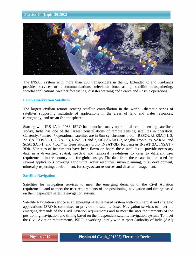
The INSAT system with more than 200 transponders in the C, Extended C and Ku-bands
provides services to telecommunications, television broadcasting, satellite newsgathering,
societal applications, weather forecasting, disaster warning and Search and Rescue operations.
Earth Observation Satellites
The largest civilian remote sensing satellite constellation in the world - thematic series of
satellites supporting multitude of applications in the areas of land and water resources;
cartography; and ocean & atmosphere.
Starting with IRS-1A in 1988, ISRO has launched many operational remote sensing satellites.
Today, India has one of the largest constellations of remote sensing satellites in operation.
Currently, *thirteen* operational satellites are in Sun-synchronous orbit – RESOURCESAT-1, 2,
2A CARTOSAT-1, 2, 2A, 2B, RISAT-1 and 2, OCEANSAT-2, Megha-Tropiques, SARAL and
SCATSAT-1, and *four* in Geostationary orbit- INSAT-3D, Kalpana & INSAT 3A, INSAT -
3DR. Varieties of instruments have been flown on board these satellites to provide necessary
data in a diversified spatial, spectral and temporal resolutions to cater to different user
requirements in the country and for global usage. The data from these satellites are used for
several applications covering agriculture, water resources, urban planning, rural development,
mineral prospecting, environment, forestry, ocean resources and disaster management.
Satellite Navigation
Satellites for navigation services to meet the emerging demands of the Civil Aviation
requirements and to meet the user requirements of the positioning, navigation and timing based
on the independent satellite navigation system.
Satellite Navigation service is an emerging satellite based system with commercial and strategic
applications. ISRO is committed to provide the satellite based Navigation services to meet the
emerging demands of the Civil Aviation requirements and to meet the user requirements of the
positioning, navigation and timing based on the independent satellite navigation system. To meet
the Civil Aviation requirements, ISRO is working jointly with Airport Authority of India (AAI)
Physics 2019 Physics-04 (Leph_201502) Electronic Device
Physics-04 (Leph_201502)
in establishing the GPS Aided Geo Augmented Navigation (GAGAN) system. To meet the user
requirements of the positioning, navigation and timing services based on the indigenous system,
ISRO is establishing a regional satellite navigation system called Indian Regional Navigation
Satellite System (IRNSS).
GPS Aided GEO Augmented Navigation (GAGAN):
This is a Satellite Based Augmentation System (SBAS) implemented jointly with Airport
Authority of India (AAI). The main objectives of GAGAN are to provide Satellite-based
Navigation services with accuracy and integrity required for civil aviation applications and to
provide better Air Traffic Management over Indian Airspace. The system will be interoperable
with other international SBAS systems and provide seamless navigation across regional
boundaries. The GAGAN Signal-In-Space (SIS) is available through GSAT-8 and GSAT-10.
His is an independent Indian Satellite based positioning system for critical National applications.
The main objective is to provide Reliable Position, Navigation and Timing services over India
and its neighbourhood, to provide fairly good accuracy to the user. The IRNSS will provide
basically two types of services
1. Standard Positioning Service (SPS)
2. Restricted Service (RS)
To date, ISRO has built a total of nine satellites in the IRNSS series; of which eight are currently
in orbit Three of these satellites are in geostationary orbit (GEO) while the remaining in
geosynchronous orbits (GSO) that maintain an inclination of 29° to the equatorial plane. The
IRNSS constellation was named as “NavIC” (Navigation with Indian Constellation) by the
Honourable Prime Minister, Mr. Narendra Modi and dedicated to the nation on the occasion of
the successful launch of the IRNSS-1G satellite. The eight operational satellites in the IRNSS
series, namely IRNSS-1A, 1B, 1C, 1D, 1E, 1F, 1G and 1I were launched on Jul 02, 2013; Apr
04, 2014; Oct 16, 2014; Mar 28, 2015; Jan 20, 2016; Mar 10, 2016, Apr 28, 2016; and Apr 12,
2018 respectively. The PSLV-39 / IRNSS-1H being unsuccessful; the satellite could not reach
orbit.
Experimental satellites
A host of small satellites mainly for the experimental purposes. These experiments include
Remote Sensing, Atmospheric Studies, Payload Development, Orbit Controls, recovery
technology etc.
Sub 500 kg class satellites - a platform for stand-alone payloads for earth imaging and science
missions within a quick turnaround time.
Scientific research
Physics 2019 Physics-04 (Leph_201502) Electronic Device
Physics-04 (Leph_201502)
Spacecraft for research in areas like astronomy, astrophysics, planetary and earth sciences,
atmospheric sciences and theoretical physics.
ISRO's Student Satellite programme is envisaged to encourage various Universities and
Institutions for the development of Nano/Pico Satellites.
9. SUMMARY
Role of atmosphere on propagation of em waves:
Earth’s atmosphere allows em waves of visible range to pass through it that is why sunlight
reaches earth.
The atmosphere’s ozone layer blocks UV radiations.
The clouds block infra-red radiation that is why it is warmer in cloudy night.
EM waves up to 40 MHz are reflected back by different layers of ionosphere.
EM waves above 40MHz penetrate through the ionosphere and travel in a straight line. These
are used in satellite communication.
EM waves of few KHz to 3MHz glides near the earth surface.
EM waves travel in in three modes:
i) Ground wave propagation
ii) Sky wave propagation and
iii) Space wave propagation
Ground wave propagation:
Ground wave or surface wave propagation is a mode of propagation in which the wave moves
close to earth’s surface. It is suitable for low frequencies few KHz to 3MHz.Due to
attenuation and diffraction, this mode of propagation is suitable for local broadcast like AM
broadcast of medium wave band of frequency range 530KHz to 1710Khz.This attenuation
increases rapidly with increase in frequency of wave and with increase in distance. This mode
of communication is used at airports, marine, trade fairs, shopping malls or local mela.
Sky wave propagation:
It is the mode of wave propagation in which the waves reach receiver antenna after reflection
from ionosphere. This mode of propagation is suitable for frequency range 3MHz to 40MHz.
Due to reflection from ionosphere; this mode of propagation is useful for long distance
communication. So, it is used for short wave broadcast services.
Physics 2019 Physics-04 (Leph_201502) Electronic Device
Physics-04 (Leph_201502)
Different frequencies are reflected by different layers of ionosphere. The maximum frequency
that a layer of ionosphere can reflect back is called its Critical frequency.
The ionosphere extends from 65Km to 400Km above earth surface. Ionization occur due to
absorption of UV and other high energy radiations coming from sun by air molecules.
The degree of ionization varies with the height. The top layers and bottom layers of ionosphere
have low density of ions.
In top most layers of ionosphere, the ionizing radiation of sun is quite strong but the air
molecules to be ionized are small in number, hence low density of ions in top most layers. In
bottom most layers, the no. of air molecules are quite large but the ionizing radiation of sun is
weak. So, only small number of molecules can be ionized, hence low density of ions in bottom
layers of ionosphere. The reflection phenomenon from layers of ionosphere is similar to total
internal reflection of light in optics.
Space wave communication:
It is the mode of propagation in which wave travels in a straight line from transmitting antenna to
receiving antenna through space. This mode of communication is suitable for frequencies above
40MHz.
Since the waves travel in a straight line from transmitting antenna to receiving antenna, these
space waves are used for line of sight (LOS) communication.
Space waves are used for television broadcast, microwave links, cell phones and satellite
communication.
Due to straight line nature of space waves, these waves are sometimes blocked by earth’s
curvature. To overcome such problem height of both transmitting antenna and receiving antenna
should be raised.
Satellite communication:
In this mode of communication, the receiver antenna receives signals from transmitting antenna
through satellite.
The transmitter located on earth sends signal to the satellite, this process is called Uplink. The
satellite sends the signal to receiving station located on earth. This process of sending the signal
to receiving station is called Downlink.
The uplink and downlink frequencies are different. Uplink frequencies are 5.925 – 6.425 GHz
and downlink frequencies are 3.7 – 4.2 GHz. It is so to avoid Interference between uplink and
Physics 2019 Physics-04 (Leph_201502) Electronic Device
Physics-04 (Leph_201502)
downlink waves. Interference is a phenomenon in which there occurs redistribution of energy of
two waves meeting at a place.