physics for scientists and engineers ii, summer semester 2009 1 lecture 25: july 27 th 2009 physics...
Post on 20-Dec-2015
221 views
TRANSCRIPT

Physics for Scientists and Engineers II , Summer Semester 2009
1
Lecture 25: July 27th 2009
Physics for Scientists and Engineers II

Physics for Scientists and Engineers II , Summer Semester 2009
2
Image Formation by Refraction on Spherical Surface
O
p
21 nn
2n
R
I
1n
1
2
P
d
C
q
2211
22221111
21
sin and sin
small) and ( rays paraxialonly Consider
nn
nnnn

Physics for Scientists and Engineers II , Summer Semester 2009
3
Image Formation by Refraction on Spherical Surface
O
p
21 nn
2n
R
I
1n
1
2
P
d
C
q
2211 nn
2
1
1221
21
nnnn
nn
q
d
R
d
p
d tantantan
:ionapproximatAnother
R
nn
q
n
p
n
R
dnn
q
dn
p
dnnnnn
1221
12211221

Physics for Scientists and Engineers II , Summer Semester 2009
4
Magnification for Refraction on Spherical Surface
p
21 nn
2n
I
1n
1
2
P
C
q
2211 nn
h
'h
2
1
1
2'
n
n
p
q
p
q
h
hM
21
' and : approx. angle Small
q
h
p
h
p
q
n
n
h
hM
2
1'

Physics for Scientists and Engineers II , Summer Semester 2009
5
Sign Conventions for Refracting Surfaces
Positive Negative
Object Location (p) Real Object
(in front of surface)
Virtual Object
(in the back of surface)
Image Location (q) Real Image
(in the back of surface)
Virtual Image
(in front of the surface)
Image height (h’) Image is Upright Image is Inverted
Radius (R) Center of curvature is in the back of surface
Center of curvature is in front of surface
Magnification (M) Image is Upright Image is Inverted
R
nn
q
n
p
n 1221

Physics for Scientists and Engineers II , Summer Semester 2009
6
Flat Refracting Surfaces
pn
nq
q
n
p
n
q
n
p
n
R
nn
q
n
p
n
1
221
211221 0R where,
Note: The sign of q is always opposite that of p image and object are always on the same side for flat surfaces.
Physics for Scientists and Engineers II , Summer Semester 2009
7
Example: Flat Refracting Surfaces
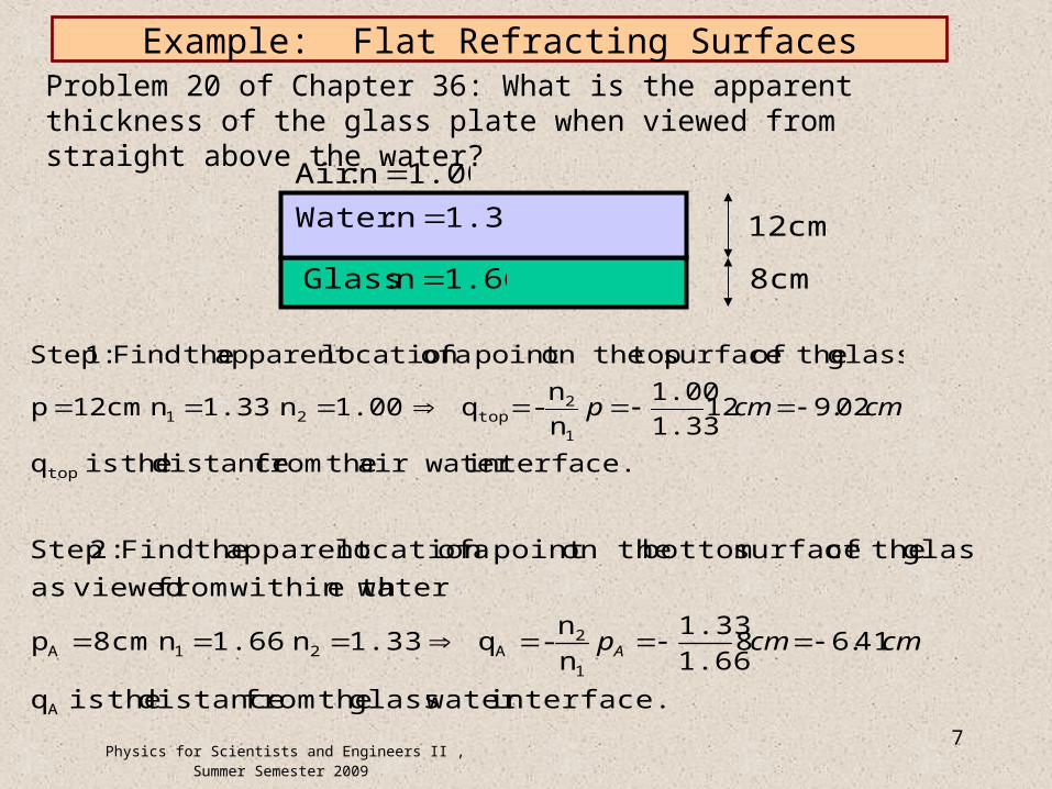
interface.air water thefrom distance theis q
02.9121.33
1.00
n
n- q 1.00n 1.33n 12cmp
glass. theof surface topon thepoint a oflocation apparent theFind :1 Step
top
1
2top21 cmcmp
Problem 20 of Chapter 36: What is the apparent thickness of the glass plate when viewed from straight above the water?
12cm
8cm1.66n :Glass
1.33n :Water
1.00n :Air
interface. water glass thefrom distance theis q
41.681.66
1.33
n
n- q 1.33n 1.66n 8cmp
watere within thfrom viewedas
glass theof surface bottom on thepoint a oflocation apparent theFind :2 Step
A
1
2A21A cmcmpA
Physics for Scientists and Engineers II , Summer Semester 2009
8
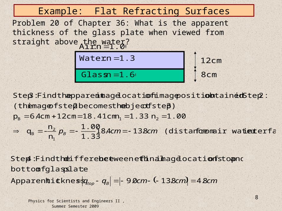
Example: Flat Refracting SurfacesProblem 20 of Chapter 36: What is the apparent thickness of the glass plate when viewed from straight above the water?
12cm
8cm1.66n :Glass
1.33n :Water
1.00n :Air
interface)air water from (distance8.134.181.33
1.00
n
n- q
1.00n 1.33n 18.41cm12cmcm4.6p
3) step ofobject thebecomes 2 step of image (the
:2 Stepin obtainedposition image oflocation imageapparent theFind :3 Step
1
2B
21B
cmcmpB
cmcmcmqq Btop 8.48.130.9hicknessApparent t
:plate glass of bottom
and topof locations image final ebetween th difference theFind :4 Step

Physics for Scientists and Engineers II , Summer Semester 2009
9
Lenses
A lens is basically an object with two refracting surfaces through which light passes.We start with two spherical surfaces having radii R1 and R2. How to calculate the image distance? Use the image created by surface 1 as theobject for surface 2.
2p
1p
1q
O1I
1C
n
11 n1R 2R
t
tqtqp 112
11 :negative) is (q virtualis I If
Physics for Scientists and Engineers II , Summer Semester 2009
10
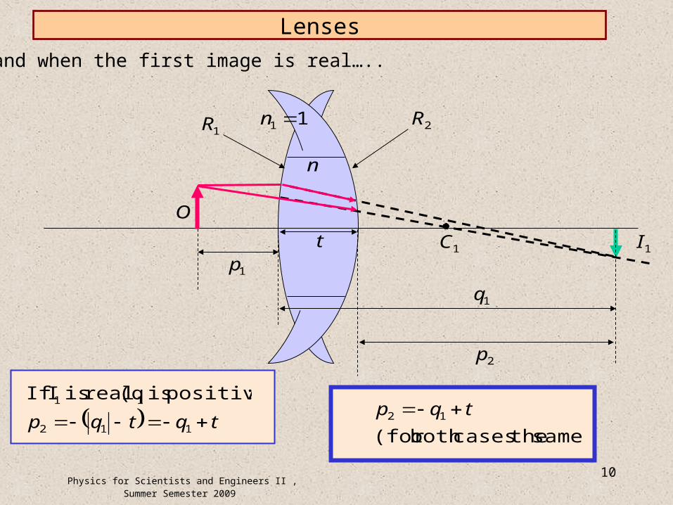
Lenses
….and when the first image is real…..
2p
1p
1q
O
1I1C
n
11 n1R 2R
t
tqtqp 112
11 :positive) is (q real is I If
same) thecasesboth (for
12 tqp

Physics for Scientists and Engineers II , Summer Semester 2009
11
THIN Lenses
11
and 1 :surfacefirst on RefractionFor
111
21
1221
R
n
q
n
p
nn n
R
nn
q
n
p
n
11
11
1and :surface secondon RefractionFor
221
222
21
R
n
n
R
n
qp
n
n nn
LENSESTHINfor where 112 qtqp
add
11
111
2121
RRn
qp
11
111
21
RRn
qp
11
11
21
RRn
f
equation makers'-Lens
fqp
111

Physics for Scientists and Engineers II , Summer Semester 2009
12
Sign Conventions for Thin Lenses
Positive Negative
Object Location (p) Real Object
(in front of lens)
Virtual Object
(in the back of lens)
Image Location (q) Real Image
(in the back of lens)
Virtual Image
(in front of lens)
Image height (h’) Image is Upright Image is Inverted
Radii (R1 and R2) Center of curvature is in the back of lens
Center of curvature is in front of lens
Focal length (f) A converging lens A diverging lens
p
q
RRn
ffqp
h
h'Mand
111
1where
111
21
Note: Lenses always have TWO focal points (one for each direction of incident light).

Physics for Scientists and Engineers II , Summer Semester 2009
13
Ray Diagrams for Thin Lenses
1F
2F
Incoming Ray Outgoing Ray
Parallel to Principal Axis Through Focal Point F2
Through Focal Point F1 Parallel to Principal Axis
Through Center of Lens Goes Straight Through
O
I

Physics for Scientists and Engineers II , Summer Semester 2009
14
Ray Diagrams for Thin Lenses
1F
2F
Incoming Ray Outgoing Ray
Parallel to Principal Axis Through Focal Point F2
Through Focal Point F1 Parallel to Principal Axis
Through Center of Lens Goes Straight Through
OI
You need to traceoutgoing raysback to wherethey seem to comefrom to find thevirtual image location.