physics of the heart: from the macroscopic to the microscopic xianfeng song advisor: sima...
TRANSCRIPT

Physics of the Heart: From the macroscopic to the microscopic
Xianfeng Song
Advisor: Sima Setayeshgar
January 9, 2007

Outline
Part I: Transport Through the Myocardium of
Pharmocokinetic Agents Placed in the Pericardial Sac: Insights From Physical Modeling
Part II: Electrical Wave Propagation in a Minimally
Realistic Fiber Architecture Model of the Left Ventricle
Part III: Calcium Dynamics in the Myocyte

Part I: Transport Through the Myocardium of Pharmocokinetic Agents Placed in the
Pericardial Sac: Insights From Physical Modeling
Xianfeng Song, Department of Physics, Indiana University
Keith L. March, IUPUI Medical School
Sima Setayeshgar, Department of Physics, Indiana University

Motivation: Diffusion in Biological Processes Diffusion is the dominant transport mechanism in
biology, operative on many scales:
Intracellular [1]
The rate of protein diffusion in the cytoplasm constrains a variety of cellular functions and limit the rates and accuracy of biochemical signaling in vivo.
Multicellular [2]
Diffusion plays an important role during the early embryonic pattern formation in establishing and constraining accuracy of morphogen prepatterns.
Tissue-level [3]
Diffusion controls delivery of glucose and oxygen from the vascular system to tissue cells and also governs movement of signaling molecules between cells.
[1] Elowitz, M. B., M. G. Surette, et al. (1999). J. Bact. 181(1): 197-203.[2] Gregor, T., W. Bialek, R. de Ruyter van Steveninck, et al. (2005). PNAS 102(51).[3] Nicholson, C. (2001), Rep. Prog. Phys. 64, 815-884.
Need for careful characterization of diffusion constants governing various biophysical processes.
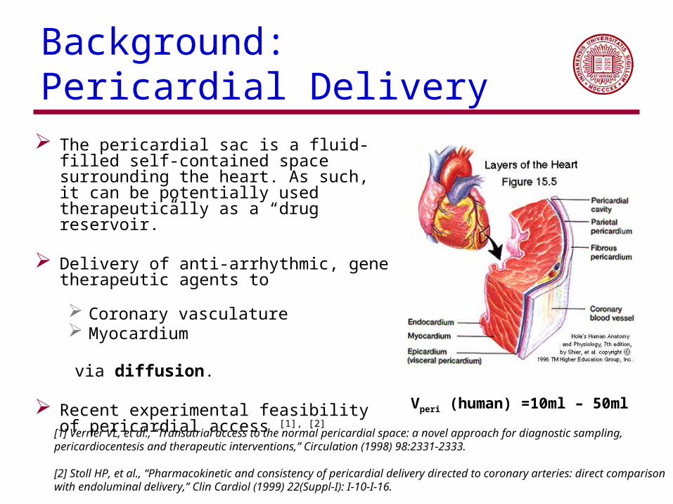
Background: Pericardial Delivery
The pericardial sac is a fluid-filled self-contained space surrounding the heart. As such, it can be potentially used therapeutically as a “drug reservoir.”
Delivery of anti-arrhythmic, gene therapeutic
agents to
Coronary vasculature Myocardium
via diffusion.
Recent experimental feasibility of pericardial access [1], [2]
Vperi (human) =10ml – 50ml
[1] Verrier VL, et al., “Transatrial access to the normal pericardial space: a novel approach for diagnostic sampling, pericardiocentesis and therapeutic interventions,” Circulation (1998) 98:2331-2333.
[2] Stoll HP, et al., “Pharmacokinetic and consistency of pericardial delivery directed to coronary arteries: direct comparison with endoluminal delivery,” Clin Cardiol (1999) 22(Suppl-I): I-10-I-16.

Part 1: Outline
Experiments
Mathematical modeling
Comparison with data
Conclusions

Experiments
Experimental subjects: juvenile farm pigs
Radiotracer method to determine the spatial concentration profile from gamma radiation rate, using radio-iodinated test agents
Insulin-like Growth Factor (125I-IGF, MW: 7734 Da) Basic Fibroblast Growth Factor (125I-bFGF, MW: 18000 Da)
Initial concentration delivered to the pericardial sac at t=0
200 or 2000 g in 10 ml of injectate
Harvesting at t=1h or 24h after delivery

Experimental Procedure
At t = T (1h or 24h), sac fluid is distilled: CP(T)
Tissue strips are submerged in liquid nitrogen to fix concentration.
Cylindrical transmyocardial specimens are sectioned into slices: Ci
T(x,T) x denotes
CT(x,T) = i CiT(x,T)
x: depth in tissue
i

Mathematical Modeling
Goals
Determine key physical processes, and extract governing parameters Assess the efficacy of agent penetration in the myocardium using this
mode of delivery
Key physical processes
Substrate transport across boundary layer between pericardial sac and myocardium:
Substrate diffusion in myocardium: DT
Substrate washout in myocardium (through the intramural vascular and lymphatic capillaries): k

Idealized Spherical Geometry
Pericardial sac: R2 – R3
Myocardium: R1 – R2
Chamber: 0 – R1
R1 = 2.5cm
R2 = 3.5cm
Vperi= 10ml - 40ml

Governing Equations and Boundary Conditions Governing equation in myocardium: diffusion + washout
CT: concentration of agent in tissue DT: effective diffusion constant in tissue k: washout rate
Pericardial sac as a drug reservoir (well-mixed and no washout): drug number
conservation
Boundary condition: drug current at peri/epicardial boundary

Example of Numerical Fits to Experiments
Agent Concentration Error surface

Fit Results
Numerical values for DT, k, consistent for IGF, bFGF

Time Course from Simulation
Parameters: DT = 7×10⁻⁶cm2s-1 k = 5×10⁻⁴s-1 = 3.2×10⁻⁶cm2s2

Effective Diffusion, D*, in Tortuous Media
Stokes-Einstein relation D: diffusion constant R: hydrodynamic radius : viscosity T: temperature
Diffusion in tortuous medium D*: effective diffusion constant D: diffusion constant in fluid
: tortuosity
For myocardium, = 2.11. (from M. Suenson, D.R. Richmond, J.B. Bassingthwaighte, “Diffusion of sucrose, sodium, and water in ventricular myocardium, American Joural of Physiology,” 227(5), 1974 )
Numerical estimates for diffusion constants
IGF : D ~ 4 x 10⁻⁷ cm2s-1
bFGF: D ~ 3 x 10⁻⁷ cm2s-1
Our fitted values are in order of 10-6 - 10-5 cm2sec-1, 10 to 50 times larger !!

Transport via Intramural Vasculature
Drug permeates into vasculature from extracellular space at high concentration and permeates out of the vasculature into the extracellular space at low concentration, thereby increasing the effective diffusion constant in the tissue.
Epi
Endo

Diffusion in Active Viscoelastic Media
Heart tissue is a porous medium consisting of extracellular space and muscle fibers. The extracellular space consists of an incompressible fluid (mostly water) and collagen.
Expansion and contraction of the fiber bundles and sheets leads to changes in pore size at the tissue level and therefore mixing of the extracellular volume. This effective "stirring" [1] results in larger diffusion constants.
[1] T. Gregor, W. Bialek, R. R. de Ruyter, van Steveninck, et al., PNAS 102, 18403 (2005).

Part I: Conclusions
Model accounting for effective diffusion and washout is consistent with experiments despite its simplicity.
Quantitative determination of numerical values for physical parameters Effective diffusion constant IGF: DT = (1.7±1.5) x 10-5 cm2s-1, bFGF: DT = (2.4±2.9) x 10-5 cm2s-1
Washout rate IGF: k = (1.4±0.8) x 10-3 s-1, bFGF: k = (2.1±2.2) x 10-3 s-1
Peri-epicardial boundary permeability IGF: = (4.6±3.2) x 10-6 cm s-1, bFGF: =(11.9±10.1) x
10-6 cm s-1
Enhanced effective diffusion, allowing for improved transport
Feasibility of computational studies of amount and time course of pericardial drug delivery to cardiac tissue, using experimentally derived values for physical parameters.

Part II:Electrical Wave Propagation in a
Minimally Realistic Fiber Architecture Model of the Left Ventricle: Dynamics
of Phase SingulariesXianfeng Song, Department of Physics, Indiana University
Sima Setayeshgar, Department of Physics, Indiana University

Part II: Outline
Motivation
Model Construction
Numerical Results
Conclusions and Future Work


The Heart as a Physical System
Ventricular fibrillation (VF) is the main cause of sudden cardiac death in industrialized nations, accounting for 1 out of 10 deaths.
Strong experimental evidence suggests that self-sustained waves of electrical wave activity in cardiac tissue are related to fatal arrhythmias.
Mechanisms that generate and sustain VF are poorly understood.
Conjectured mechanism:
Breakdown of a single spiral (scroll) wave into a disordered state, resulting from various mechanisms of spiral wave instability.
W.F. Witkowksi, et al., Nature 392, 78 (1998)
Patch size: 5 cm x 5 cmTime spacing: 5 msec

Focus of this work
Distinguish the role in the generation of electrical wave instabilities of the “passive” properties of cardiac tissue as a conducting medium
geometrical factors (aspect ratio and curvature)
rotating anisotropy (rotation of mean fiber direction through heart wall)
bidomain description (intra- and extra-cellular spaces treated separately)
from its “active” properties, determined by cardiac cell electrophysiology.

From idealized to fully realistic geometrical modeling
Rectangular slab Anatomical canine ventricular model
Minimally realistic model of LV for studying electrical wave propagation in three dimensional anisotropic myocardium that adequately addresses the role of geometry and fiber architecture and is:
Simpler and computationally more tractable than fully realistic models
Easily parallelizable and with good scalability
More feasible for incorporating realistic electrophysiology, electromechanical coupling,
J.P. Keener, et al., in Cardiac Electrophysiology, eds.D. P. Zipes et al. (1995)
Courtesy of A. V. Panfilov, in Physics Today, Part 1, August 1996
bidomain description

LV Fiber Architecture
Early dissection results revealed nested ventricular fiber surfaces, with fibers given approximately by geodesics on these surfaces.
Fibers on a nested pair of surfaces in the LV,from C. E. Thomas, Am. J. Anatomy (1957).
Anterior view of the fibers on Hog Ventricles, which reveals the nested ventricular fiber surfaces,from C. E.
Thomas, Am. J. Anatomy (1957).

Peskin asymptotic model: Fundamental principles and Assumptions The fiber structure has axial symmetry
The fiber structure of the left ventricle is in near-equilibrium with the pressure gradient in the wall
The state of stress in the ventricular wall is the sum of a hydrostatic pressure and a fiber stress
The cross-sectional area of a fiber tube does not vary along its length
The thickness of the fiber structure is considerably smaller than its other dimensions.
Mcqueen & Peskin Mathematical model on heart
Crossection area of Peskin’s asymptotic model

Peskin Asymptotic model: Conclusions
Fiber angle profile through LV thickness: Comparison of Peskin asymptotic model and dissection results
Cross-section of the predicted middle surface (red line) and fiber surfaces (solid lines) in the r, z-plane.
The fibers run on a nested family of toroidal surfaces which are centered on a degenerate torus which is a circular fiber in the equatorial plane of the ventricle
The fiber are approximate geodesics on fiber surfaces, and the fiber tension is approximately constant on each surface
The fiber-angle distribution through the thickness of the wall follows an inverse-sine relationship
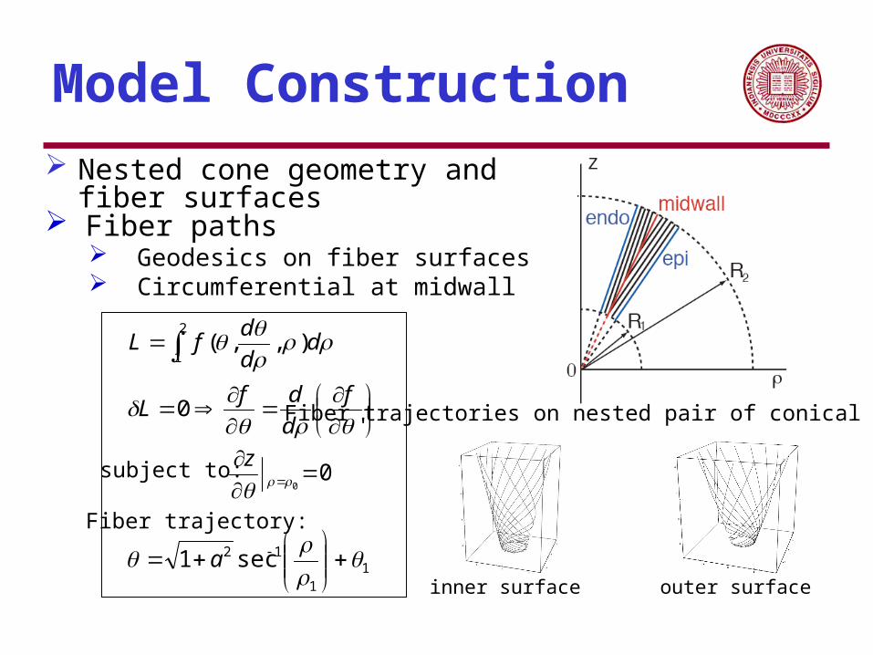
Model Construction Nested cone geometry and fiber surfaces
Fiber paths Geodesics on fiber surfaces Circumferential at midwall
'0
),,(2
1
f
d
dfL
dd
dfL
00
z
11
12 sec1
a
subject to:
Fiber trajectory:
Fiber trajectories on nested pair of conical surfaces:
inner surface outer surface
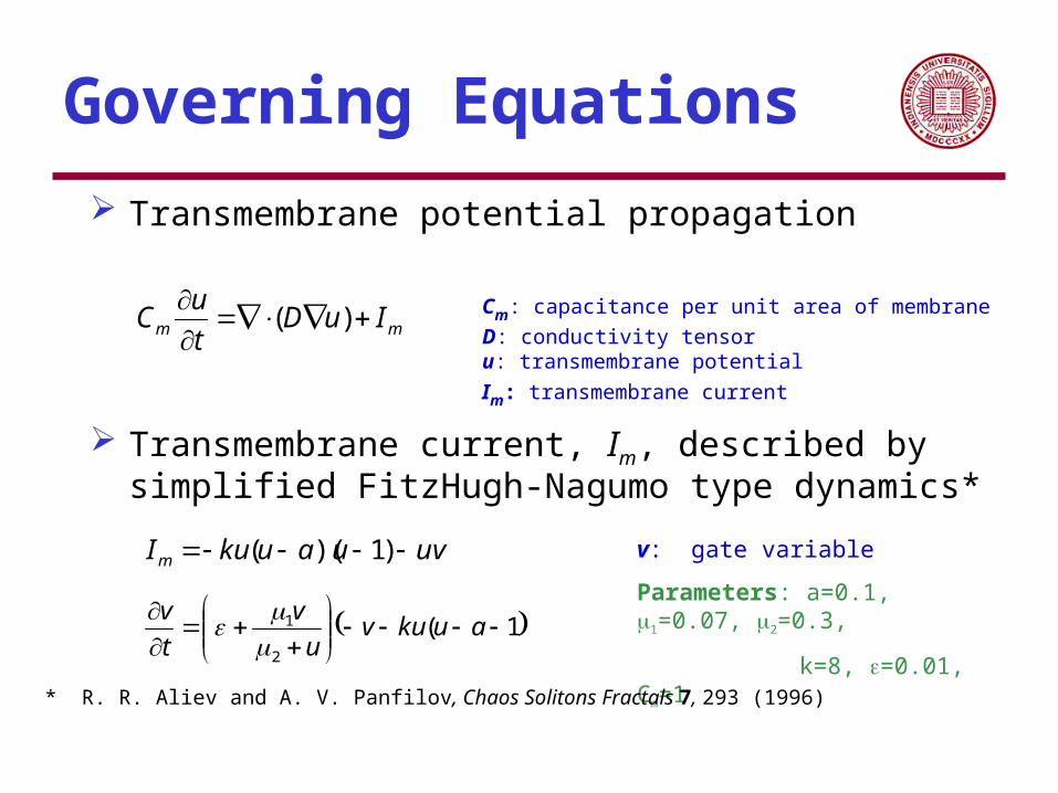
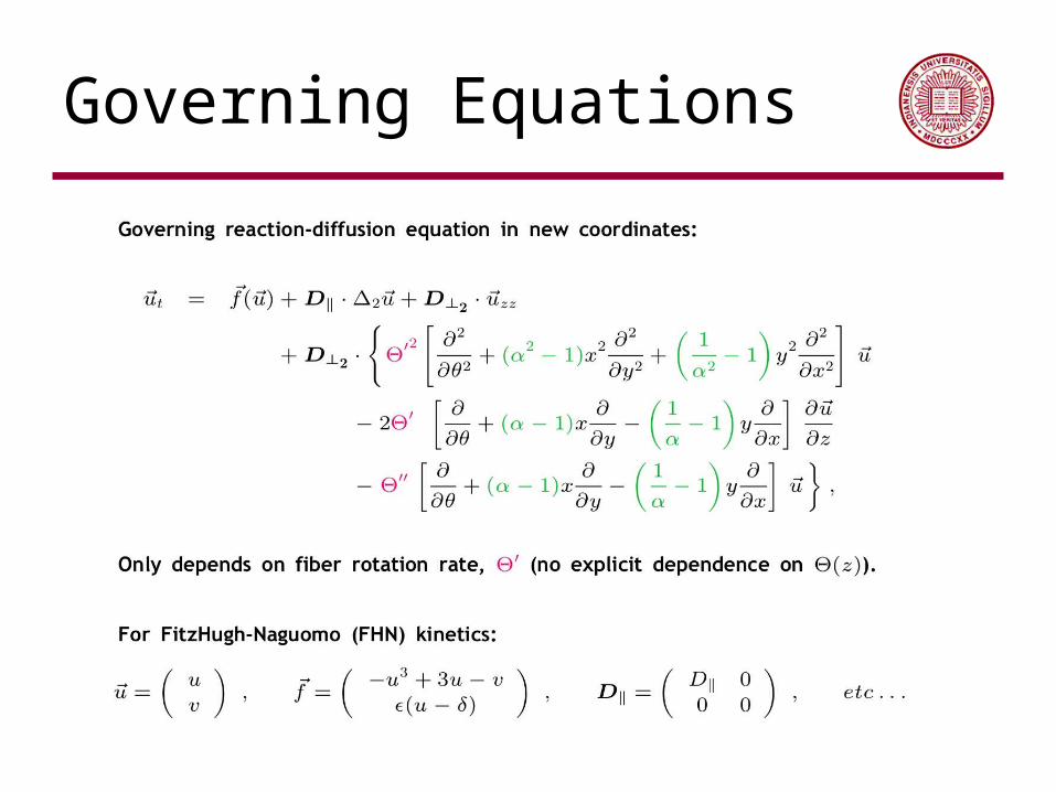
Governing Equations
Transmembrane potential propagation
Transmembrane current, Im, described by simplified FitzHugh-Nagumo type dynamics*
mm IuDt
uC
)(
1(2
1
aukuvu
v
t
v
uvuaukuIm )1)(( v: gate variable
Parameters: a=0.1, 1=0.07, 2=0.3,
k=8, =0.01, Cm=1
* R. R. Aliev and A. V. Panfilov, Chaos Solitons Fractals 7, 293 (1996)
Cm: capacitance per unit area of membrane
D: conductivity tensoru: transmembrane potential
Im: transmembrane current
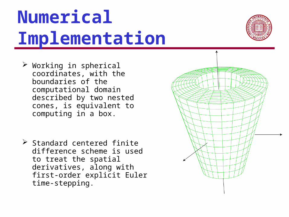
Numerical Implementation
Working in spherical coordinates, with the boundaries of the computational domain described by two nested cones, is equivalent to computing in a box.
Standard centered finite difference scheme is used to treat the spatial derivatives, along with first-order explicit Euler time-stepping.

Conductivity Tensor
2
1
//
00
00
00
p
plocal
D
D
D
D
Local Coordinate Lab Coordinate
Transformation matrix R
RDRD locallab1
Parallelization
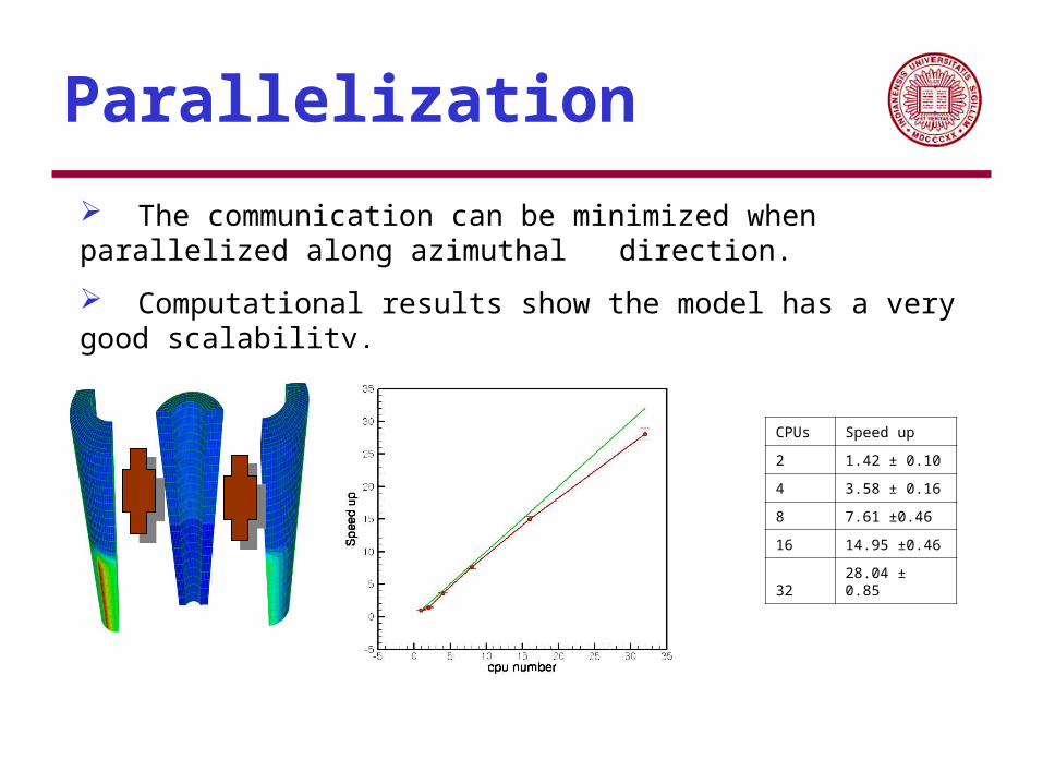
The communication can be minimized when parallelized along azimuthal direction.
Computational results show the model has a very good scalability.
CPUs Speed up
2 1.42 ± 0.10
4 3.58 ± 0.16
8 7.61 ±0.46
16 14.95 ±0.46
32 28.04 ± 0.85

Phase Singularities
Color denotes the transmembrane potential.
Movie shows the spread of excitation for 0 < t < 30, characterized by a single filament.
Tips and filaments are phase singularities that act as organizing centers for spiral (2D) and scroll (3D) dynamics, respectively, offering a way to quantify and simplify the full spatiotemporal dynamics.

Keener’s Theory of Filament Dynamics
Consider the system described by a "reaction-diffusion" system of the form
Assume the system has the two-dimensional solution (i.e. independent of one spatial dimensions, say z) in the form of a stationary rotating vortex
By using singular perturbation theory, one can get the evolution equation for filament:
is the vortex rotation phaseR: is a point on the filamentN: the normal T: the tangentB: the binormal unit vectork: the curvature: tortion of the filament
J. Keener, P., Physica D 31, 269 (1988).

Tension of organizing filaments of scroll wave
V. N. Biktashev etc simplify evolution equation to
By analyzing the total length of filament, one can get:
The coefficient b2 plays a very special role in the dynamics of the filament. Its sign uniquely determines whether the length of the filament increases or decreases irrespective of the form of the filament and the values of the other parameters of the medium. Due to this property, the coefficient b2 can be reasonably called the filament tension.
V. N. Biktashev, A. V. Holden, and H. Zhang, Philosophical Transactions: Physical Sciences and engineering 347, 611 (1994)

Filament-finding Algorithm
Find all tips
“Distance” between two tips: If two tips are not on a same fiber surface or on adjacent surfaces, the distance is defined to be infinity. Otherwise, the distance is the distance along the fiber surface

Filament-finding Algorithm
Random choose a tip
“Distance” between two tips: If two tips are not on a same fiber surface or on adjacent surfaces, the distance is defined to be infinity. Otherwise, the distance is the distance along the fiber surface

Filament-finding Algorithm
Search for the closest tip
“Distance” between two tips: If two tips are not on a same fiber surface or on adjacent surfaces, the distance is defined to be infinity. Otherwise, the distance is the distance along the fiber surface

Filament-finding Algorithm
Make connection
“Distance” between two tips: If two tips are not on a same fiber surface or on adjacent surfaces, the distance is defined to be infinity. Otherwise, the distance is the distance along the fiber surface

Filament-finding Algorithm
Continue doing search
“Distance” between two tips: If two tips are not on a same fiber surface or on adjacent surfaces, the distance is defined to be infinity. Otherwise, the distance is the distance along the fiber surface

Filament-finding Algorithm
Continue
“Distance” between two tips: If two tips are not on a same fiber surface or on adjacent surfaces, the distance is defined to be infinity. Otherwise, the distance is the distance along the fiber surface

Filament-finding Algorithm
Continue
“Distance” between two tips: If two tips are not on a same fiber surface or on adjacent surfaces, the distance is defined to be infinity. Otherwise, the distance is the distance along the fiber surface

Filament-finding Algorithm
Continue
“Distance” between two tips: If two tips are not on a same fiber surface or on adjacent surfaces, the distance is defined to be infinity. Otherwise, the distance is the distance along the fiber surface

Filament-finding Algorithm
The closest tip is too far
“Distance” between two tips: If two tips are not on a same fiber surface or on adjacent surfaces, the distance is defined to be infinity. Otherwise, the distance is the distance along the fiber surface

Filament-finding Algorithm
Reverse the search direction
“Distance” between two tips: If two tips are not on a same fiber surface or on adjacent surfaces, the distance is defined to be infinity. Otherwise, the distance is the distance along the fiber surface

Filament-finding Algorithm
Continue
“Distance” between two tips: If two tips are not on a same fiber surface or on adjacent surfaces, the distance is defined to be infinity. Otherwise, the distance is the distance along the fiber surface
Filament-finding Algorithm
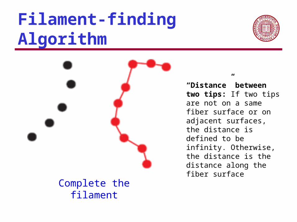
Complete the filament
“Distance” between two tips: If two tips are not on a same fiber surface or on adjacent surfaces, the distance is defined to be infinity. Otherwise, the distance is the distance along the fiber surface

Filament-finding Algorithm
Start a new filament
“Distance” between two tips: If two tips are not on a same fiber surface or on adjacent surfaces, the distance is defined to be infinity. Otherwise, the distance is the distance along the fiber surface
Filament-finding Algorithm
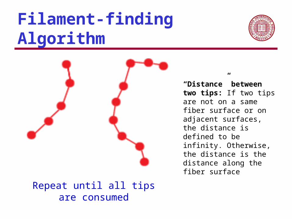
Repeat until all tips are consumed
“Distance” between two tips: If two tips are not on a same fiber surface or on adjacent surfaces, the distance is defined to be infinity. Otherwise, the distance is the distance along the fiber surface

Filament-finding result
FHN Model: t = 2
t = 999
Numerical Convergence
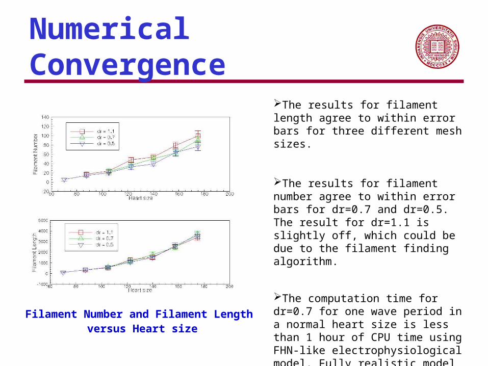
Filament Number and Filament Length versus Heart size
The results for filament length agree to within error bars for three different mesh sizes.
The results for filament number agree to within error bars for dr=0.7 and dr=0.5. The result for dr=1.1 is slightly off, which could be due to the filament finding algorithm.
The computation time for dr=0.7 for one wave period in a normal heart size is less than 1 hour of CPU time using FHN-like electrophysiological model. Fully realistic model requires several days per heart cycle on a high-performance machine (Hunter, P. J., A. J. Pullan, et al. (2003). "MODELING TOTAL HEART FUNCTION." Annual Review of Biomedical Engineering 5(1): 147-177)

Scaling of Ventricular Turbulence
Both filament length
These results are in agreement with those obtained with the fully realistic canine anatomical model, using the same electrophysiology.
A. V. Panfilov, Phys. Rev. E 59, R6251 (1999)
Log(total filament length) and Log(filament number) versus Log(heart size)
The average filament length, normalized by average heart thickness, versus heart size

Work in progress
The role of fiber architectureWhether the anisotropy in our model induce instability or suppress instability of wave propagation
The role of geometryWhat is the role of cone geometry comparing with the simple rectangular slab given the same physiological model.

Rotating anisotropy

Coordinate System
Governing Equations

Perturbation Analysis

Scroll Twist Solutions

Filament Motion

Filament Motion

Filament motion (cont’d)

Filament Tension

Conclusions and Future Work
We have constructed and implemented a minimally realistic fiber architecture model of the left ventricle for studying electrical wave propagation in the three dimensional myocardium.
Our model adequately addresses the geometry and fiber architecture of the LV, as indicated by the agreement of filament dynamics with that from fully realistic geometrical models.
Our model is computationally more tractable, allowing reliable numerical studies. It is easily parallelizable and has good scalability.
As such, it is more feasible for incorporating Realistic electrophysiology Bidomain description of tissue Electromechanical coupling

Part III:Calcium Dynamics in myocyte
Xianfeng Song, Department of Physics, Indiana University
Sima Setayeshgar, Department of Physics, Indiana University

Part III: Outline
The importance and background of calcium signaling in myocyte
Future work

Overview of Calcium Signaling
Berridge, M. J., M. D. Bootman, et al. (1998). "Calcium - a life and death signal." Nature 395(6703): 645-648.
Elementary events (red) result from the entry of external Ca2+ across the plasma membrane or release from internal stores in the endolasmic or sarcoplasmic reticulum (ER/SR).
Global Ca2+signals are produced by coordinating the activity of elementary events to produce a Ca 2+ wave that spreads throughout the cell.
The activity of neighboring cells within a tissue can be coordinated by an intercellular wave that spreads from one cell o the next.

Fundamental elements of Ca2+ signaling machinery
Calcium stores: External and internal stores, i.e. Endoplasmic Reticulum (ER), Sarcoplasmic Reticulum (SR), Mitochondria
Calcium buffers: Calcium is heavily buffered in all cells, with at least 99% of the available Ca2+ bound to large Ca2+-binding proteins., such as Calmodulin, Calsequestrin.
Calcium pumps: Ca2+ is moved to Calcium stores by varies pumps.
Calcium channels: Ca2+ can enter the cytoplasm from calcium stores via varies channels, i.e. ryanodine receptors (RyR) and inositol trisphosphate receptors (IP3R).
Borisyuk, A. (2005). Tutorials in mathematical biosciences. Berlin, Springer

Receptor clustering
RyR and IP3R channels are spatially organized in clusters, with the distance between clusters are approximate two order magnitude larger than the distances between channels within one cluster.
Chemotaxis receptors in E.coli are organized in clusters, proven to make: Noise reduction
Signal amplification
High resolution image showing a Ca2+ puff evoked by photoreleased InsP3 which demonstrate an IP3R cluster (From Yao,
Y. etc, Journal of Physiology 482: 533-553.)
Skoge, M. L., R. G. Endres, et al. (2006), Biophys. J. 90(12): 4317-4326.

Ventricular Myocyte
Some facts about myocyteThe typical cardiac myocyte is a cylindrical cell approximately 100 m in length by 10m in diameter
Three physical compartments: the cytoplasm, the sarcoplasmic reticulum (SR) and the mitochondria.
The junctional cleft is a very narrow space between the SL and the SR membrane.
Calcium Induced Cacium Release (CICR)A small amount of Ca2+ goes into the junctional cleft thus induce large scale of Ca2+ release from calcium stores (mainly SR).
Excitation-Contraction Coupling (ECC)The depolarization of the membrane initial a small amount of Ca2+, thus induce CICR and initiate contraction.
Borisyuk, A. (2005). Tutorials in mathematical biosciences. Berlin, Springer
Ventricular Myocyte Structure
Calcium induced Calcium release

The role of Calsequestrin
Calsequestrin is the buffer inside SR, most of which are located close to RyRs.
Calsequestrins play an important role during CICR.
One proposal about Calsequestrin: (A) The channel opens, Ca2+ adsorbed to linear CSQ polymers feeds rapid release. (B) The polymers are depleted Ca2+ thus disassemble. (C)
Depletion becomes deeper as Ca2+ replenishes the proximate store and the CSQ polymers reassembles. (from Launikonis etc, PNAS 103(8) 2982-7
Borisyuk, A. (2005). Tutorials in mathematical biosciences. Berlin, Springer

Calmodulin
A kind of calcium-binding proteins which contains four calcium binding sites. The binding on both terminal domains are in the cooperative manner.
Calmodulin undergoes a conformational change upon binding to calcium, which enables it to bind to specific proteins for a specific response.
The Protein Data Bank. Nucleic Acids Research, 28 pp. 235-242 (2000).Shifman et al. PNAS, 103 (38): 13968

Future directions
Why receptors are clustering together? What is the design principle underlying the receptor clustering?
To fully understand the role of Calsequestrin: how best can Calsequestrin facilitate the calcium release?
The role of cooperativity of Calcium binding to Calmodulin as noise reduction in calcium signaling pathway?

Thanks!!

Overview of Calcium Signals Calcium serves as an important signaling messenger.
Extracellular sensing The regulation of cardiac contractility by Ca2+
Ca2+ signaling during embryogenesis
Calcium sparks and waves
Spiral Ca2+ wave in the Xenopus oocytes. The image size is 420x420 um. The spiral has a wavelength of about 150 um and a period of about
8 seconds. Part B is simulation.
Ca sparks in an isolated mouse ventricular myocyte. Mechanically stimulated
intercellular wave in airway epithelial cells
Borisyuk, A. (2005). Tutorials in mathematical biosciences. Berlin, Springer
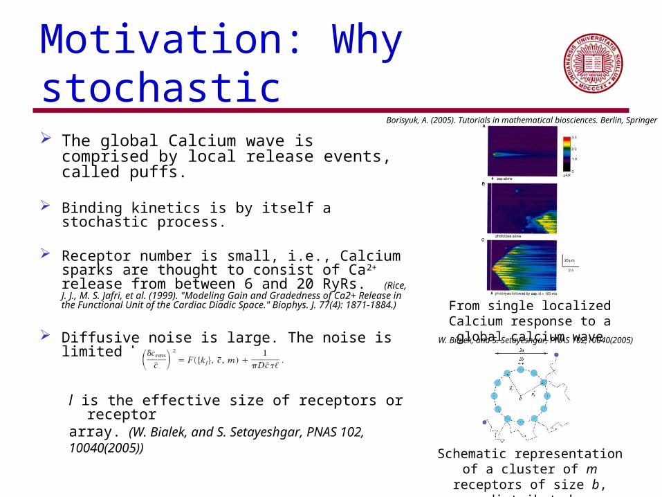
Motivation: Why stochastic
The global Calcium wave is comprised by local release events, called puffs.
Binding kinetics is by itself a stochastic process.
Receptor number is small, i.e., Calcium sparks are thought to consist of Ca2+ release from between 6 and 20 RyRs. (Rice, J. J., M. S. Jafri, et al. (1999). "Modeling Gain and Gradedness of Ca2+ Release in the Functional Unit of the Cardiac Diadic Space." Biophys. J. 77(4): 1871-1884.)
Diffusive noise is large. The noise is limited by
l is the effective size of receptors or receptorarray. (W. Bialek, and S. Setayeshgar, PNAS 102,10040(2005))
From single localized Calcium response to a global calcium wave
Schematic representation of a cluster of m receptors of size b, distributed
uniformly on a ring of size a.
W. Bialek, and S. Setayeshgar, PNAS 102,10040(2005)
Borisyuk, A. (2005). Tutorials in mathematical biosciences. Berlin, Springer

Ventricular Myocyte
The typical cardiac myocyte is a cylindrical cell approximately 100 m in length by 10m in diameter and is surrounded by a cell membrane known as the sarcolemma (SL)
Three physical compartments: the cytoplasm, the sarcoplasmic reticulum (SR) and the mitochondria.
The junctional cleft is a very narrow space between the SL and the SR membrane.
Borisyuk, A. (2005). Tutorials in mathematical biosciences. Berlin, Springer
Ventricular Myocyte Structure

Calcium signaling in Ventricular Myocyte
Ca-Induced Ca Release (CICR)A small amount of Ca2+ goes into the junctional cleft thus induce large scale of Ca2+ release from calcium stores (mainly SR).
Excitation-Contraction Coupling (ECC)The depolarization of the membrane initial a small amount of Ca2+, thus induce CICR and initiate contraction.
Borisyuk, A. (2005). Tutorials in mathematical biosciences. Berlin, Springer