physics–based simulation of agile robotic systems
TRANSCRIPT

Proceedings of the ASME 2019International Mechanical Engineering Congress and Exposition
IMECE2019November 11-14, 2019, Salt Lake City, UT, USA
IMECE2019-11345
PHYSICS–BASED SIMULATION OF AGILE ROBOTIC SYSTEMS
Pavel Piliptchak∗, Murat Aksu, Frederick M. Proctor, John L. MichaloskiNational Institute of Standards and Technology
Gaithersburg, MD
ABSTRACTDevelopment and testing of industrial robot environments
is hampered by the limited availability of hardware resources.Simulations provide a more accessible and readily modifiablealternative to physical testing, but also require careful designto maximize their fidelity to the real system. In this paper, wedescribe new progress in building an entirely physics-drivensimulation of the Agility Performance of Robotic Systems(APRS) Laboratory at the National Institute of Standards andTechnology (NIST). To maximize the accuracy of physics-basedinteractions in this environment, we develop several general-purpose improvements to the simulation of parallel grippersand multi-object collisions. We use pick-and-place tasks fromthe APRS Laboratory as well as generic benchmarks to verifythe performance of our simulation. We demonstrate that ourproposed improvements result in more physically-consistentsimulations compared to standard implementations, regardlessof the choice of physics engine or simulation parameters.
Keywords: robotics, agility, grasping, pick-and-place, simu-lation
1 INTRODUCTION
Simulations are invaluable tools in developing industrial roboticsystems. In situations where hardware resources are limited orcostly to use, simulations can provide a test-bench for developingcontrollers, debugging software, and testing various work-spaceconfigurations [1]. One of the limiting factors to using a simula-
∗Contact author: [email protected]
tion in place of a real system is how well it replicates the physicaldynamics of the real system. This discrepancy has inspired thedevelopment of new rigid-body physics engines that tackle spe-cific problem areas, such as numerically stable contacts and jointarticulations [2–4].
However, existing robotics simulators are not a one-size-fits-all solution. A significant amount of effort needs to be putinto defining contact behavior, inertia matrices, friction coeffi-cients, and numerical solver parameters to ensure acceptable per-formance [5]. This effort becomes increasingly laborious as thesimulated environment becomes more complex.
In this work, we use the Robot Operating System (ROS)[6] and the Gazebo [7] robotics simulator to build an entirelyphysics-based simulation of the APRS Laboratory, an environ-ment designed for evaluating the capabilities of robots perform-ing industrial pick-and-place tasks [8]. This environment is fairlydifficult to replicate with standard simulators due to the largenumber of small, low-mass objects that the robot must accuratelymanipulate. Along the course of building this simulation, we de-veloped several practical and general-purpose improvements tosimulating two important components of our pick-and-place task(namely parallel grippers and multi-object collisions).
This work presents the following contributions:
1. A complete simulation of the APRS Laboratory that inte-grates with existing APRS software
2. A simple controller for simulated parallel grippers that im-proves grasp stability
3. A method for simplifying contacts between many relativelystationary objects in simulation
1

In the following sections, we will (1) discuss relevant ex-periments in physics-based simulation at NIST and abroad; (2)describe the design of our APRS Laboratory simulation; (3) de-scribe our two improvements mentioned above; and (4) presentexperiments verifying the benefits of these improvements.
2 RELATED WORK
Despite the popularity of Gazebo for robot simulation, there havebeen comparatively few publications that use it for physics-basedgrasping and manipulation—particularly in full-fledged, realisticenvironments. The most notable example is the Defense Ad-vanced Research Projects Agency (DARPA) Virtual RoboticsChallenge (VRC) which required grasping as part of several sub-tasks [9, 10]. Simulations have also been used for the dexterousmanipulation of cloth [11], pick-and-place tasks [12], and dexter-ous reinforcement learning agents [13]. The robots in these sim-ulations generally use high degree-of-freedom (DOF), anthropo-morphic hands. They also generally handle palm-fitting objectsrather than smaller objects that require fingertip-only grasps. Incontrast, the APRS simulation robots use parallel grippers andmanipulate peg-like objects with diameters that are under 1 cm.
Another angle of research has been verifying the physicalaccuracy of the physics engines themselves [14–16] with someworks emphasizing grasping in particular [17, 18]. Often, thisresearch seeks out general benchmarks that measure either: 1)how the engine’s compute speed scales with simulation com-plexity; 2) how well the engine conserves energy/momentum; or3) how far the engine deviates from some ground-truth behaviorfor a simple dynamical system. We verify the accuracy of theAPRS simulation using similar methods (to be discussed in theExperiments section), but focus on benchmarks that are relevantto grasping and pick-and-place tasks. We do not make claimsabout the general accuracy of the tested physics engines.
NIST has also pursued research in verifying the physical ac-curacy of robot simulators [19,20]. This earlier work focused onthe simulation of the Talon Robot using the older Karma PhysicsEngine. The evaluation metrics used in this work were based pri-marily on mobility with limited discussion of grasping. In con-trast, our work simulates a pick-and-place task using Gazebo’svariant of the Open Dynamics Engine (ODE) [2, 5]. It focusesmore finely on grasp stability and simulator performance.
3 SYSTEM OVERVIEW
In this section, we give a high-level overview of our APRS sim-ulation. We will begin by reviewing the objectives and design ofthe physical APRS Laboratory. Following this, we will presentthe design of our simulation along with its interfaces to the exist-ing APRS architecture.
APRS ArchitectureThe APRS Laboratory seeks to study and measure the “agility”of robotics systems, which widely refers to a system’s retask-ing capability, robustness to failures, and interoperability [8]. Aspart of this research effort, the APRS Laboratory implements anarchetypal agile robotics system that operates on a simple pick-and-place kitting task.
The system consists of a Fanuc LR-Mate 200iD and a Mo-toman SIA20F robot. These two robots are positioned on op-posite sides of a conveyor, which carries several part trays con-taining gears. These gears must be moved by the robots (bothequipped with parallel gripper end-effectors) to a specified kittray. As the robots perform the kitting task, the system experi-ences several mock failures, such as a robot breaking down or apart being misplaced.
Reacting to these failures requires an agile approach to sens-ing, planning, and control—the details of which can be foundin [8]. To briefly summarize:
1. The APRS Laboratory maintains an ontology describing rel-evant kitting objects and concepts
2. An overhead camera system is used to locate instances ofobjects described in this ontology
3. A planner uses the ontology and instance information to gen-erate a high-level action plan
4. Low-level controllers execute this plan on the robots
In the described architecture, replacing the physical system witha simulation requires three steps: replicating the camera system,replicating the robot grasping dynamics, and creating an inter-face between the high-level plan and the low-level virtual con-trollers used by the simulated robots. Virtual sensors were ex-plored in [21], while implementing a shared interface and achiev-ing accurate dynamics is this work’s focus.
Simulation FrameworkThe APRS simulation framework is built primarily using ROS,which is an open-source suite of robotics-related software pack-ages that are interconnected through a shared message-passingframework. Out of the box, ROS packages provide us with thekinematic descriptions of the robots, joint controllers, joint-stateinformation, forward/inverse kinematic solvers, and collision-aware trajectory planning. ROS can also be extended by writ-ing new packages, which is how we implement the kinematicdescriptions of the conveyor and parallel grippers in the system.
We use Gazebo, an open-source robotics simulator, to dy-namically simulate the system. Gazebo is designed to be compat-ible with many of ROS’s components, including the robot kine-matic descriptions, joint controllers, and joint-state publishers.Gazebo also supports multiple physics engines and allows usersto tune the behavior of each engine’s numerical solver. We willprovide a detailed discussion our choice of physics parametersand physics engine in the “Experiments” section.
2
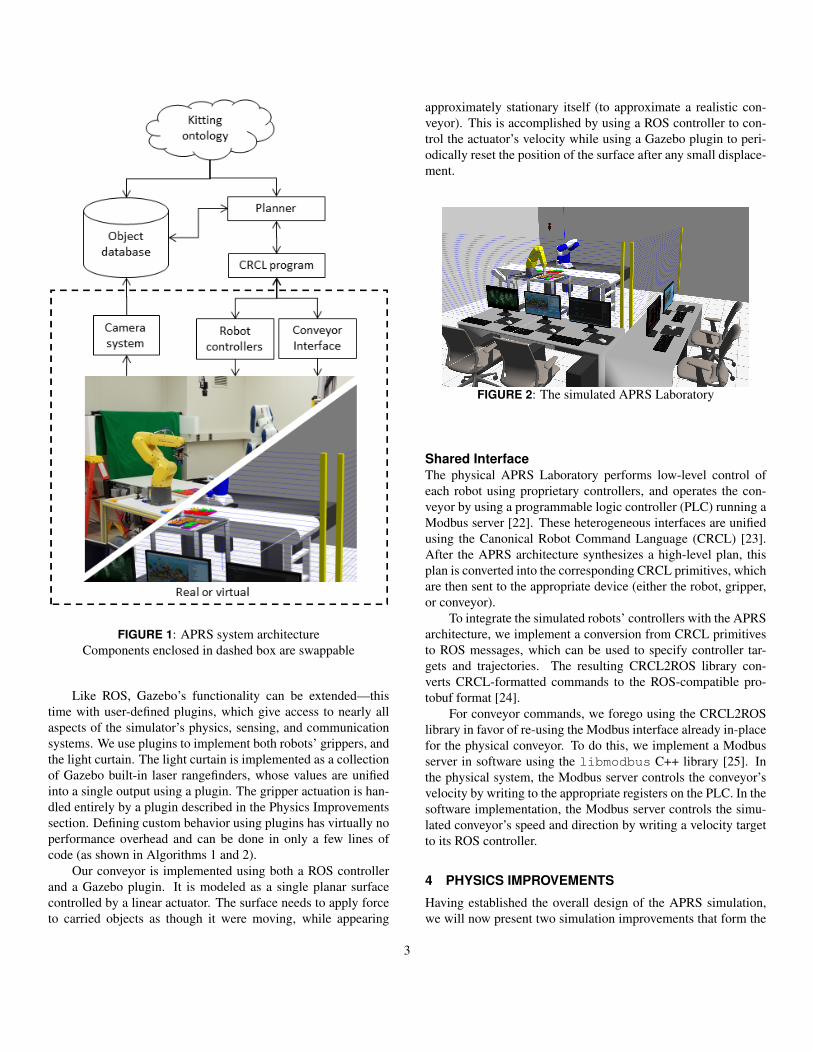
FIGURE 1: APRS system architectureComponents enclosed in dashed box are swappable
Like ROS, Gazebo’s functionality can be extended—thistime with user-defined plugins, which give access to nearly allaspects of the simulator’s physics, sensing, and communicationsystems. We use plugins to implement both robots’ grippers, andthe light curtain. The light curtain is implemented as a collectionof Gazebo built-in laser rangefinders, whose values are unifiedinto a single output using a plugin. The gripper actuation is han-dled entirely by a plugin described in the Physics Improvementssection. Defining custom behavior using plugins has virtually noperformance overhead and can be done in only a few lines ofcode (as shown in Algorithms 1 and 2).
Our conveyor is implemented using both a ROS controllerand a Gazebo plugin. It is modeled as a single planar surfacecontrolled by a linear actuator. The surface needs to apply forceto carried objects as though it were moving, while appearing
approximately stationary itself (to approximate a realistic con-veyor). This is accomplished by using a ROS controller to con-trol the actuator’s velocity while using a Gazebo plugin to peri-odically reset the position of the surface after any small displace-ment.
FIGURE 2: The simulated APRS Laboratory
Shared InterfaceThe physical APRS Laboratory performs low-level control ofeach robot using proprietary controllers, and operates the con-veyor by using a programmable logic controller (PLC) running aModbus server [22]. These heterogeneous interfaces are unifiedusing the Canonical Robot Command Language (CRCL) [23].After the APRS architecture synthesizes a high-level plan, thisplan is converted into the corresponding CRCL primitives, whichare then sent to the appropriate device (either the robot, gripper,or conveyor).
To integrate the simulated robots’ controllers with the APRSarchitecture, we implement a conversion from CRCL primitivesto ROS messages, which can be used to specify controller tar-gets and trajectories. The resulting CRCL2ROS library con-verts CRCL-formatted commands to the ROS-compatible pro-tobuf format [24].
For conveyor commands, we forego using the CRCL2ROSlibrary in favor of re-using the Modbus interface already in-placefor the physical conveyor. To do this, we implement a Modbusserver in software using the libmodbus C++ library [25]. Inthe physical system, the Modbus server controls the conveyor’svelocity by writing to the appropriate registers on the PLC. In thesoftware implementation, the Modbus server controls the simu-lated conveyor’s speed and direction by writing a velocity targetto its ROS controller.
4 PHYSICS IMPROVEMENTS
Having established the overall design of the APRS simulation,we will now present two simulation improvements that form the
3

main contribution of this paper. Each improvement targets acomponent of the simulated system that is prone to unstable,physically unrealistic behavior. “Stability” will be defined andtested more precisely in the “Experiments” section, while thissection will focus on the conceptual description of each improve-ment. We want to stress that these improvements are agnostic tothe physics engine used and are simple to implement providedthe physics engine supports a programming interface (this is han-dled by Gazebo’s plugin system in our case).
Parallel Gripper ControlThe APRS robots perform grasping using pneumatic parallelgrippers. A typical approach for defining parallel grippers insoftware involves mimic joints, where one joint “mimics” a sec-ond joint by maintaining its relative position and velocity in joint-space. Unfortunately, many physics engines do not define a jointconstraint that describes this mimic behavior directly. Becauseof this, a popular ad-hoc approach is to use external control plu-gins [26]. This approach implements a proportional-integral-derivative (PID) force controller that uses the mimic joint’s rela-tive joint position as the feedback term. However, there are twoproblems with using such a control scheme for parallel grasping.
• The output force is 0 N when the error feedback is 0 (i.e.,when the gripper’s fingers are symmetrically positioned).During grasping, this creates asymmetric forces on the grip-per that either cause the grasp to fail or the mimic joint to bepushed to an asymmetric position so that the force generatedby the controller matches the force of the original joint.
• Since the original joint’s controller has no knowledge of themimic joint, there is no guarantee that the gripper’s fingerswill remain symmetric throughout a trajectory if they expe-rience different external forces. For example, if an obstacleblocks the mimic joint but not the original joint, the result-ing finger positions would not be symmetric like they wouldbe in the real gripper.
To address these shortcomings, we implement a new controlscheme operating on both joints simultaneously:
F1 = Fc + kp(p2− p1), (1)F2 = Fc + kp(p1− p2). (2)
Here, Fi is the force output for each joint; pi is the joint-spaceposition of each joint; Fc is a constant force shared by both joints;and kp is a proportional gain. Using this controller, both jointsmaintain an identical non-zero force during grasps and are drivento symmetric positions by mimicking each other, satisfying bothproblems.
This control scheme has an elegant physical interpretation:the Fc term emulates the force generated by the gripper’s piston,
and the kp(·) term emulates the normal forces of the gripper’sactuator linkage.
While this controller was developed with pneumatic grip-per’s in mind, it can easily be extended for approximating anymimic joint(s). Given some collection of N mimic joints, asingle-joint force-controller Fj, and a relative joint-error force-controller Fs, we can define the control of joint i ∈ {1 . . .N} as:
Fi = Fj(pi)+ ∑n∈{1...N}\{i}
Fs(pn− pi). (3)
In our gripper implementation, Fj(·) was chosen to be the con-stant force Fc. Fs(·) was chosen to be a proportional controller.
Contact SimplificationThe kitting tasks performed by APRS robots involve handlingdozens of small objects such as gears and trays. This intro-duces two challenges to simulation. The first challenge is simu-lation stability. The stacking of objects, especially objects withlarge inertia-ratios, is known to cause instability due to over-constraining the linear complementarity problems (LCPs) thatare solved by the physics engine at each time step [5]. The sec-ond challenge is compute speed, which deteriorates as the num-ber of contacts to simulate increases.
To improve both stability and computational performance,we implement a Gazebo plugin for automatically simplifyingcontacts between relatively stationary objects. The approach isstraightforward in concept:
1. Use Gazebo’s built-in ContactSensor class to find ex-isting contacts and their contact forces
2. Determine whether the objects in contact are stationary rel-ative to each other
3. Create a virtual, fixed joint between objects satisfying thestationary criteria and disable collisions between them
4. Destroy the virtual joint and re-enable collisions if the ob-jects are no longer stationary, resuming normal behavior
Effectively, this replaces a dynamics problem for the physicsengine with a much nicer statics problem for the plugin. Thesensing of forces, creation and destruction of joints, and en-abling and disabling of collisions can be handled entirely throughGazebo’s programming interface. This only leaves the questionof how to define the stationary criteria.
For our purposes, two objects are considered stationary iftheir relative velocity and acceleration are 0. These criteria workfine for creating a virtual joint, but are problematic for deletingit since the virtual joint constrains the relative velocity and ac-celeration of the objects to be 0. However, we can observe theforce needed for the virtual joint to satisfy these constraints anduse that as part of the criteria.
4

More precisely, we can define the net force Fσ on a relativelystationary object as:
Fσ = FE +FC +FV = 0, (4)
where FE is the external, non-measurable force, FC is the con-tact force, and FV is the virtual joint force. Since only one ofeither contact forces or joint forces are active at any one time,this equation becomes:
Fσ = FE +FC = 0 Fσ = FE +FV = 0. (5)
Solving and substituting for FE , we have FC = FV at the time-step that the virtual joint is created. If FC 6= FV at a future time-step, then the external force FE has changed and the original sta-tionary criteria Fσ = FE + FC = 0 is no longer satisfied. Theactual plugin uses a threshold on ‖FC−FV‖ rather than a strictinequality, but behaves equivalently.
This plugin offers an improvement over previous dynamics-disabling features found in Gazebo’s primary physics engine,which only applied to absolutely stationary objects [5]. It isalso fairly physics engine-agnostic and lightweight, provided thephysics engine supports measuring constraint forces and dynam-ically spawning joints. The complete pseudocode is given in Al-gorithms 1 and 2.
Data: GazeboContactSensorMessage Msg,ErrorThreshold e1, ErrorThreshold e2Result: VirtualJoint V, ContactForce CF
Executed on new ContactSensorMessagec1← Msg.collision1c2← Msg.collision2
v1← GetWorldFrameVelocity (c1)v2← GetWorldFrameVelocity (c2)
a1← GetWorldFrameAccel (c1)a2← GetWorldFrameAccel (c2)
if‖v1−v2‖< e1 & ‖a1−a2‖< e2 thenCF← Msg.NetForceV← GazeboCreateNewJoint(c1, c2)GazeboDisableContact(c1, c2)
endAlgorithm 1: Virtual Joint Creation Callback
5 EXPERIMENTS
In this section, we measure the performance of our two proposedimprovements. To do this, we design several scenarios that target
Data: Virtual Joint V, ContactForce CF,ErrorThreshold e
Executed on each simulation physics stepif‖CF−V.Force‖> e then
GazeboEnableContact(V.Collision1,V.Collision2)GazeboRemoveJoint(V)
endAlgorithm 2: Virtual Joint Deletion Callback
the behavior of each improvement in isolation. Each scenario andmetric is designed such that the performance of the real systemis known to be trivially simple. For example, we know that oncea real robot successfully grasps an object, the object will remaincompletely stationary relative to the gripper during any of therobot’s motions (due to the large force exerted by the pneumaticgripper). Now, the objective is to measure whether the simulationviolates this “relatively stationary” condition that is known tohold for the real system. Using this approach, we can verify thephysical accuracy of our improvements without needing to takeany measurements on the real system.
We tested our scenarios primarily with Gazebo’s variant ofODE using default simulation parameters. This configurationwas mainly used due to technical limitations in Gazebo’s supportfor other physics engines, and because this ODE configuration isfairly common in other work [1].
Parallel Gripper ControlThe gripper controller experiments are motivated primarily bythe “relatively stationary” condition described above. We con-sider a grasp more stable and physically accurate if it maintains aconstant displacement between the object and the gripper duringa motion. Mathematically, we measure this using the Euclideandistance between an initial position and subsequent positions:
δt =‖pt − p0‖2 . (6)
Here, p is a 3-dimensional relative position and t is a simulationtime-step. This metric is similar to Measure C used in [18].
We would also like to incorporate angular displacement intoour analysis. To do this, we record the quaternions q0 and qtcorresponding to initial and subsequent relative orientations be-tween the gripper and grasped object. Thus, we can computeangular displacement as:
θt = arccos(2〈qt ,q0〉2−1). (7)
We report this value along with δt (ideally both should be closeto 0 if the simulation is physically accurate). These metrics arecomputed for our gripper controller along with two baselines:
5

Standard Plugin
Cumulative δt 1.3 ·10−2 m 1.0 ·10−3 m
Real-TimeFactor
0.43 0.98
TABLE 1: Multi-object contact simplification experiment
• Constant opposing forces to both joints
• The preexisting mimic joint plugin from [26] with constantforce on the mimicked joint
Each controller is attached to a floating gripper (not expe-riencing any forces). Using each of the three controllers, thefloating gripper grasps a conveniently placed APRS gear. Oncethe gripper is closed, the floating gripper is subjected to a rangeof accelerations defined in Cartesian world coordinates (emulat-ing the motion of robots performing pick-and-place operations).During these trajectories, the positional and angular displace-ment metrics are computed and reported using a combination ofROS and Gazebo telemetry.
Our results, summarized in Figure 3, show that our proposedparallel gripper controller outperforms both baselines in min-imizing positional displacement during Cartesian trajectories.The controller also matches the constant force control schemein angular displacement. We also note that positional displace-ment was the largest contributor to objects falling out of the grip-per, and that both baselines would drop their objects from muchsmaller impulses as compared to our proposed controller.
Contact SimplificationLike our previous test, the experiment for our contact simplifica-tion improvement uses another “relatively stationary” condition.This time, we know that gears placed inside trays must be sta-tionary relative to the tray (based on their coefficient of frictionand the tray design shown in [8]). Therefore, we can reuse themetrics given by Equations 6 and 7, this time computing the rel-ative displacement from gear to tray (rather than gear to gripper).
The scenario that we used consists of a conveyor carryingmultiple trays. Each tray is loaded with gears, reminiscent of atypical kitting task. We choose this particular configuration tohighlight the benefits of our improvement to both accuracy andrun speed for simulations with scaling complexity.
We summarize our results in Table 1. This data was col-lected based on a simulation of 10 trays carrying 40 gears, whichwe believe adequately demonstrates the effect of the plugin onboth accuracy and simulation speed. We record the relative dis-placement δt between a gear and the tray at t = 4 s. We thensum the δt values from all 40 gears to compute a cumulative δtvalue for the scenario. We also record the real-time factor of thesimulation.
(a) Positional Displacement
(b) Angular DisplacementFIGURE 3: Relative displacement along a Cartesian trajectory
using various controllers
As expected, once the contact simplification plugin createsa virtual joint, the displacement of the gear relative to its trayis fixed. This gives the plugin a slight edge over the standardapproach by limiting the effect of any unstable simulation be-haviour (like jittering contacts).
The plugin also has a pronounced effect on the simulator’scompute speed. On average, every collision between objects inour simulation had about 10 contact points that needed to be pro-cessed per time step. The plugin effectively reduced this to onecontact point per collision.
6
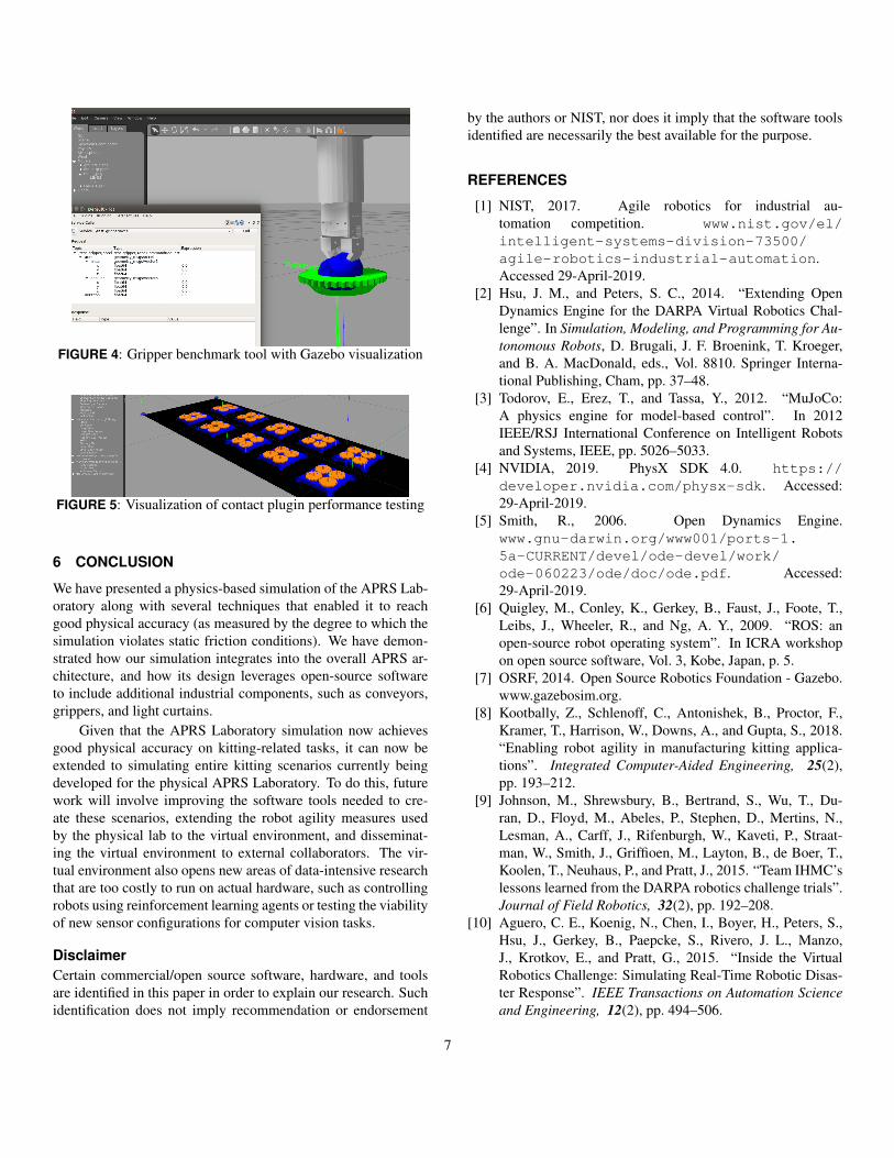
FIGURE 4: Gripper benchmark tool with Gazebo visualization
FIGURE 5: Visualization of contact plugin performance testing
6 CONCLUSION
We have presented a physics-based simulation of the APRS Lab-oratory along with several techniques that enabled it to reachgood physical accuracy (as measured by the degree to which thesimulation violates static friction conditions). We have demon-strated how our simulation integrates into the overall APRS ar-chitecture, and how its design leverages open-source softwareto include additional industrial components, such as conveyors,grippers, and light curtains.
Given that the APRS Laboratory simulation now achievesgood physical accuracy on kitting-related tasks, it can now beextended to simulating entire kitting scenarios currently beingdeveloped for the physical APRS Laboratory. To do this, futurework will involve improving the software tools needed to cre-ate these scenarios, extending the robot agility measures usedby the physical lab to the virtual environment, and disseminat-ing the virtual environment to external collaborators. The vir-tual environment also opens new areas of data-intensive researchthat are too costly to run on actual hardware, such as controllingrobots using reinforcement learning agents or testing the viabilityof new sensor configurations for computer vision tasks.
DisclaimerCertain commercial/open source software, hardware, and toolsare identified in this paper in order to explain our research. Suchidentification does not imply recommendation or endorsement
by the authors or NIST, nor does it imply that the software toolsidentified are necessarily the best available for the purpose.
REFERENCES
[1] NIST, 2017. Agile robotics for industrial au-tomation competition. www.nist.gov/el/intelligent-systems-division-73500/agile-robotics-industrial-automation.Accessed 29-April-2019.
[2] Hsu, J. M., and Peters, S. C., 2014. “Extending OpenDynamics Engine for the DARPA Virtual Robotics Chal-lenge”. In Simulation, Modeling, and Programming for Au-tonomous Robots, D. Brugali, J. F. Broenink, T. Kroeger,and B. A. MacDonald, eds., Vol. 8810. Springer Interna-tional Publishing, Cham, pp. 37–48.
[3] Todorov, E., Erez, T., and Tassa, Y., 2012. “MuJoCo:A physics engine for model-based control”. In 2012IEEE/RSJ International Conference on Intelligent Robotsand Systems, IEEE, pp. 5026–5033.
[4] NVIDIA, 2019. PhysX SDK 4.0. https://developer.nvidia.com/physx-sdk. Accessed:29-April-2019.
[5] Smith, R., 2006. Open Dynamics Engine.www.gnu-darwin.org/www001/ports-1.5a-CURRENT/devel/ode-devel/work/ode-060223/ode/doc/ode.pdf. Accessed:29-April-2019.
[6] Quigley, M., Conley, K., Gerkey, B., Faust, J., Foote, T.,Leibs, J., Wheeler, R., and Ng, A. Y., 2009. “ROS: anopen-source robot operating system”. In ICRA workshopon open source software, Vol. 3, Kobe, Japan, p. 5.
[7] OSRF, 2014. Open Source Robotics Foundation - Gazebo.www.gazebosim.org.
[8] Kootbally, Z., Schlenoff, C., Antonishek, B., Proctor, F.,Kramer, T., Harrison, W., Downs, A., and Gupta, S., 2018.“Enabling robot agility in manufacturing kitting applica-tions”. Integrated Computer-Aided Engineering, 25(2),pp. 193–212.
[9] Johnson, M., Shrewsbury, B., Bertrand, S., Wu, T., Du-ran, D., Floyd, M., Abeles, P., Stephen, D., Mertins, N.,Lesman, A., Carff, J., Rifenburgh, W., Kaveti, P., Straat-man, W., Smith, J., Griffioen, M., Layton, B., de Boer, T.,Koolen, T., Neuhaus, P., and Pratt, J., 2015. “Team IHMC’slessons learned from the DARPA robotics challenge trials”.Journal of Field Robotics, 32(2), pp. 192–208.
[10] Aguero, C. E., Koenig, N., Chen, I., Boyer, H., Peters, S.,Hsu, J., Gerkey, B., Paepcke, S., Rivero, J. L., Manzo,J., Krotkov, E., and Pratt, G., 2015. “Inside the VirtualRobotics Challenge: Simulating Real-Time Robotic Disas-ter Response”. IEEE Transactions on Automation Scienceand Engineering, 12(2), pp. 494–506.
7

[11] Bai, Y., Yu, W., and Liu, C. K., 2016. “Dexterous manipu-lation of cloth”. In Proceedings of the 37th Annual Confer-ence of the European Association for Computer Graphics,EG ’16, Eurographics Association, pp. 523–532.
[12] Qian, W., Xia, Z., Xiong, J., Gan, Y., Guo, Y., Weng, S.,Deng, H., Hu, Y., and Zhang, J., 2014. “Manipulation tasksimulation using ROS and Gazebo”. In 2014 IEEE Interna-tional Conference on Robotics and Biomimetics (ROBIO2014), IEEE, pp. 2594–2598.
[13] Rajeswaran, A., Kumar, V., Gupta, A., Vezzani, G., Schul-man, J., Todorov, E., and Levine, S., 2017. “LearningComplex Dexterous Manipulation with Deep Reinforce-ment Learning and Demonstrations”. arXiv:1709.10087[cs], Sept. arXiv: 1709.10087.
[14] Erez, T., Tassa, Y., and Todorov, E., 2015. “Simulationtools for model-based robotics: Comparison of Bullet, Ha-vok, MuJoCo, ODE and PhysX”. In 2015 IEEE Interna-tional Conference on Robotics and Automation (ICRA),IEEE, pp. 4397–4404.
[15] Chung, S.-J., and Pollard, N., 2016. “Predictable behaviorduring contact simulation: a comparison of selected physicsengines”. Computer Animation and Virtual Worlds, 27(3-4), pp. 262–270.
[16] Peters, S., and Hsu, J., 2014. Comparison of RigidBody Dynamic Simulators for Robotic Simulation inGazebo. www.osrfoundation.org/wordpress2/wp-content/uploads/2015/04/roscon2014_scpeters.pdf. Accessed: 29-April-2019.
[17] Taylor, J. R., Drumwright, E. M., and Hsu, J., 2016.“Analysis of grasping failures in multi-rigid body simula-tions”. In 2016 IEEE International Conference on Simula-tion, Modeling, and Programming for Autonomous Robots(SIMPAR), IEEE, pp. 295–301.
[18] Kim, J., Iwamoto, K., Kuffner, J. J., Ota, Y., and Pollard,N. S., 2013. “Physically Based Grasp Quality EvaluationUnder Pose Uncertainty”. IEEE Transactions on Robotics,29(6), pp. 1424–1439.
[19] Pepper, C., Balakirsky, S., and Scrapper, C., 2007. “Robotsimulation physics validation”. In Proceedings of the 2007Workshop on Performance Metrics for Intelligent Systems,ACM, pp. 97–104.
[20] Carpin, S., Lewis, M., Wang, J., Balakirsky, S., and Scrap-per, C., 2007. “USARSim: a robot simulator for researchand education”. In Proceedings 2007 IEEE InternationalConference on Robotics and Automation, IEEE, pp. 1400–1405.
[21] Aksu, M., Michaloski, J., and Proctor, F., 2018. “Virtualexperimental investigation for industrial robotics in gazeboenvironment”. In Proceedings of the 2018 InternationalMechanical Engineering Congress and Exposition, ASME.
[22] Swales, A., et al., 1999. “Open MODBUS/TCP specifica-tion”. Schneider Electric.
[23] Proctor, F., Balakirsky, S., Kootbally, Z., Kramer, T.,Schlenoff, C., and Shackleford, W., 2016. “The canoni-cal robot command language (CRCL)”. Industrial Robot:An International Journal, 43(5), pp. 495–502.
[24] Google, 2019. Protocol Buffers. developers.google.com/protocol-buffers/docs/overview?csw=1. Accessed: 29-April-2019.
[25] Raimbault, S., 2016. libmodbus: A Modbus libraryfor Linux, Mac OS X, FreeBSD, QNX and Windows.libmodbus.org.
[26] Chatzilygeroudis, K., 2019. Robotics Group GazeboPlugins. https://github.com/roboticsgroup/roboticsgroup_gazebo_plugins/. Accessed: 3-April-2019.
8