physitemp instruments inc. thermes 16 operating manual.pdf · 1 physitemp instruments inc. thermes...
TRANSCRIPT
1
Physitemp Instruments Inc.
Thermes
(Thermometry Expansion Slot)
Thermocouple Data Acquisition System for the PC
User's Guide July 13th, 1998
Rev 2 (March 19, 2004)

2
Contents
Introduction Checklist
Hardware Installation Gaining access to the expansion-slot area of your computer
Selecting a logical address for the Thermes board Identification of the ISA-8/16 expansion-board card-edge connector sockets
Software Installation Getting started - first-time operation
Main-screen Features Menu-bar Commands Button-bar Commands
Channel Labels High- and Low-alarm Limits
Temperature Displays Active Datafile
Menu-Bar Commands What the Commands Do
Optical-isolation Field installation of the opto-isolator board
Upgrading from the single-channel system. Demo. Software: variations from the fully-operational version
3
Introduction The continuing success of Physitemp's thermocouple products is based upon a 25-year
reputation as a source of high-accuracy medical-grade probes and precision instrumentation. With the introduction of the Thermes system, this tradition expands into the Microsoft Windows environments. Checklist
Before proceeding with the installation of your thermes system, please verify that the following components have been supplied: -
1 x Main interface board with mounting screw
Please note: - If you have ordered the "THERMES-ISO" option, the opto-isolator is supplied already installed on the Main interface board).
1 x 6' connector cable (16-channel systems only)
1 x 16-channel adaptor box
or 1 x Single-channel adaptor plug
1 x Setup Diskette 1 x CDRom 1 x Operating Manual
If there are any discrepancies or if you have questions, please call Physitemp Instruments immediately at 973 779 5577 or 1-800-452-8510.
Hardware Installation Gaining access to the expansion-slot area of your computer
Switch off your computer and disconnect the power cord. Locate and extract the screws that secure the top cover, which must then be removed.
The choice of where to install the Thermes board in your system is determined on the basis of mechanical convenience and necessity since all of the expansion slots share a common backplane and are, electrically speaking, identical. Therefore, use the following guidelines in selecting the location for the Thermes board: -
- In a "Tower-style" chassis, where expansion boards are installed horizontally, try to locate the Thermes board as low as possible to minimize the effects of heat rising from other components
- Avoid mechanical interference with the computer's internal power and data
cables
4
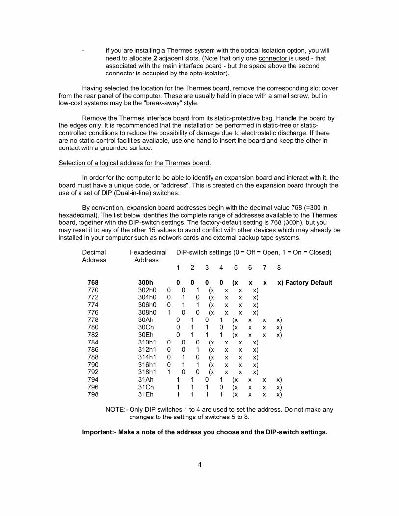
- If you are installing a Thermes system with the optical isolation option, you will need to allocate 2 adjacent slots. (Note that only one connector is used - that associated with the main interface board - but the space above the second connector is occupied by the opto-isolator).
Having selected the location for the Thermes board, remove the corresponding slot cover
from the rear panel of the computer. These are usually held in place with a small screw, but in low-cost systems may be the "break-away" style.
Remove the Thermes interface board from its static-protective bag. Handle the board by the edges only. It is recommended that the installation be performed in static-free or static-controlled conditions to reduce the possibility of damage due to electrostatic discharge. If there are no static-control facilities available, use one hand to insert the board and keep the other in contact with a grounded surface. Selection of a logical address for the Thermes board.
In order for the computer to be able to identify an expansion board and interact with it, the board must have a unique code, or "address". This is created on the expansion board through the use of a set of DIP (Dual-in-line) switches.
By convention, expansion board addresses begin with the decimal value 768 (=300 in hexadecimal). The list below identifies the complete range of addresses available to the Thermes board, together with the DIP-switch settings. The factory-default setting is 768 (300h), but you may reset it to any of the other 15 values to avoid conflict with other devices which may already be installed in your computer such as network cards and external backup tape systems.
Decimal Hexadecimal DIP-switch settings (0 = Off = Open, 1 = On = Closed) Address Address 1 2 3 4 5 6 7 8
768 300h 0 0 0 0 (x x x x) Factory Default
770 302h 0 0 0 1 (x x x x) 772 304h 0 0 1 0 (x x x x) 774 306h 0 0 1 1 (x x x x) 776 308h 0 1 0 0 (x x x x) 778 30Ah 0 1 0 1 (x x x x) 780 30Ch 0 1 1 0 (x x x x) 782 30Eh 0 1 1 1 (x x x x)
784 310h 1 0 0 0 (x x x x) 786 312h 1 0 0 1 (x x x x) 788 314h 1 0 1 0 (x x x x) 790 316h 1 0 1 1 (x x x x) 792 318h 1 1 0 0 (x x x x) 794 31Ah 1 1 0 1 (x x x x) 796 31Ch 1 1 1 0 (x x x x) 798 31Eh 1 1 1 1 (x x x x)
NOTE:- Only DIP switches 1 to 4 are used to set the address. Do not make any changes to the settings of switches 5 to 8.
Important:- Make a note of the address you choose and the DIP-switch settings.
5
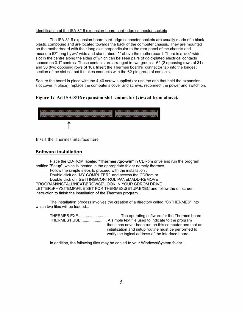
Identification of the ISA-8/16 expansion-board card-edge connector sockets
The ISA-8/16 expansion-board card-edge connector sockets are usually made of a black plastic compound and are located towards the back of the computer chassis. They are mounted on the motherboard with their long axis perpendicular to the rear panel of the chassis and measure 5" long by 3/8" wide and stand about " above the motherboard. There is a 1/16"-wide slot in the centre along the sides of which can be seen pairs of gold-plated electrical contacts spaced on 0.1" centres. These contacts are arranged in two groups:- 62 (2 opposing rows of 31) and 36 (two opposing rows of 18). Insert the Thermes board's connector tab into the longest section of the slot so that it makes connects with the 62-pin group of contacts.
Secure the board in place with the 4-40 screw supplied (or use the one that held the expansion-slot cover in place), replace the computer's cover and screws, reconnect the power and switch on.
Figure 1: An ISA-8/16 expansion-slot connector (viewed from above).
Insert the Thermes interface here
Software installation
Place the CD-ROM labeled "Thermes /tpc-win" in CDRom drive and run the program entitled "Setup", which is located in the appropriate folder namely thermes.
Follow the simple steps to proceed with the installation : Double click on “MY COMPUTER” and access the CDRom or Double click on SETTING\CONTROL PANEL\ADD-REMOVE
PROGRAM\INSTALL\NEXT\BROWSE\LOOK IN YOUR CDROM DRIVE LETTER:\PHYSITEMP\FILE SET FOR THERMES\SETUP.EXEC and follow the on screen instruction to finish the installation of the Thermes program.
The installation process involves the creation of a directory called "C:\THERMES" into which two files will be loaded...
THERMES.EXE........................... The operating software for the Thermes board THERMES1.USE........................ A simple text file used to indicate to the program
that it has never been run on this computer and that an initialization and setup routine must be performed to verify the logical address of the interface board. In addition, the following files may be copied to your Windows\System folder...
6
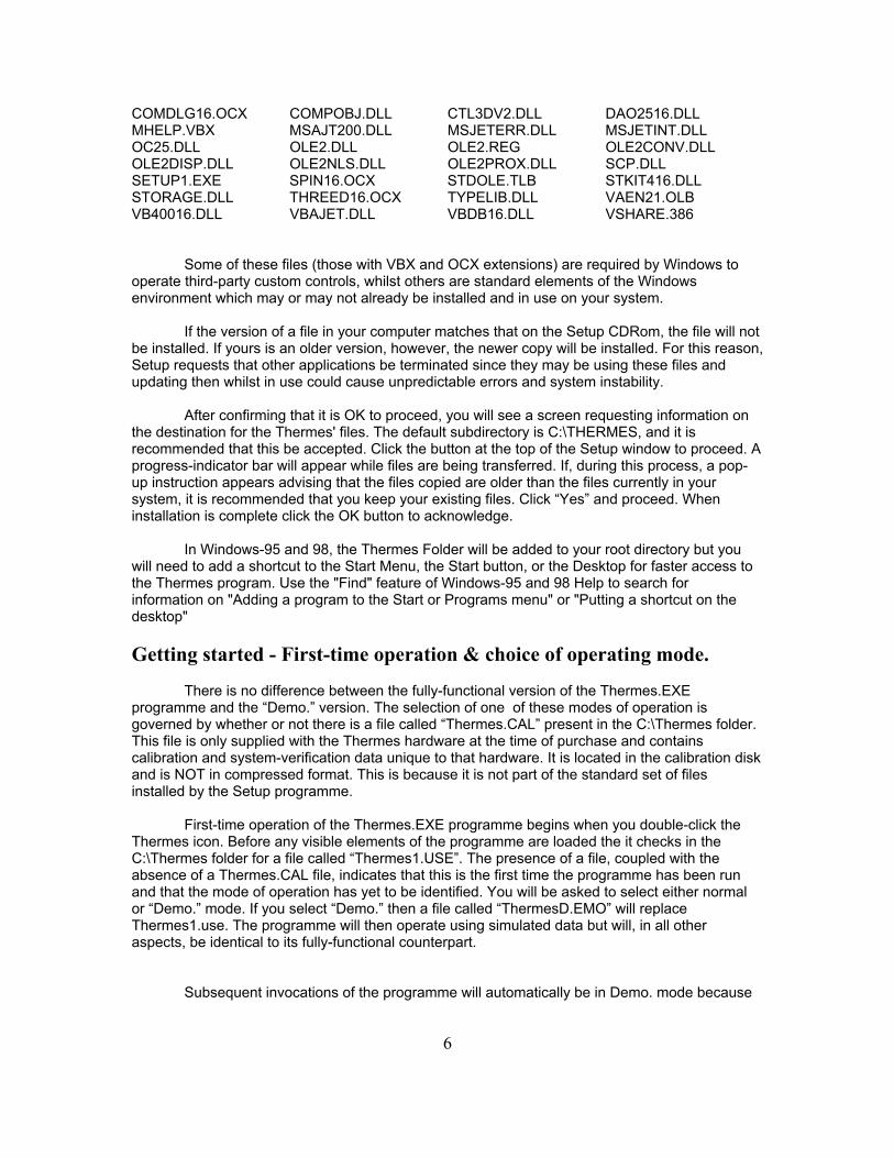
COMDLG16.OCX COMPOBJ.DLL CTL3DV2.DLL DAO2516.DLL MHELP.VBX MSAJT200.DLL MSJETERR.DLL MSJETINT.DLL OC25.DLL OLE2.DLL OLE2.REG OLE2CONV.DLL OLE2DISP.DLL OLE2NLS.DLL OLE2PROX.DLL SCP.DLL SETUP1.EXE SPIN16.OCX STDOLE.TLB STKIT416.DLL STORAGE.DLL THREED16.OCX TYPELIB.DLL VAEN21.OLB VB40016.DLL VBAJET.DLL VBDB16.DLL VSHARE.386
Some of these files (those with VBX and OCX extensions) are required by Windows to
operate third-party custom controls, whilst others are standard elements of the Windows environment which may or may not already be installed and in use on your system.
If the version of a file in your computer matches that on the Setup CDRom, the file will not be installed. If yours is an older version, however, the newer copy will be installed. For this reason, Setup requests that other applications be terminated since they may be using these files and updating then whilst in use could cause unpredictable errors and system instability.
After confirming that it is OK to proceed, you will see a screen requesting information on the destination for the Thermes' files. The default subdirectory is C:\THERMES, and it is recommended that this be accepted. Click the button at the top of the Setup window to proceed. A progress-indicator bar will appear while files are being transferred. If, during this process, a pop-up instruction appears advising that the files copied are older than the files currently in your system, it is recommended that you keep your existing files. Click “Yes” and proceed. When installation is complete click the OK button to acknowledge.
In Windows-95 and 98, the Thermes Folder will be added to your root directory but you will need to add a shortcut to the Start Menu, the Start button, or the Desktop for faster access to the Thermes program. Use the "Find" feature of Windows-95 and 98 Help to search for information on "Adding a program to the Start or Programs menu" or "Putting a shortcut on the desktop"
Getting started - First-time operation & choice of operating mode.
There is no difference between the fully-functional version of the Thermes.EXE programme and the “Demo.” version. The selection of one of these modes of operation is governed by whether or not there is a file called “Thermes.CAL” present in the C:\Thermes folder. This file is only supplied with the Thermes hardware at the time of purchase and contains calibration and system-verification data unique to that hardware. It is located in the calibration disk and is NOT in compressed format. This is because it is not part of the standard set of files installed by the Setup programme.
First-time operation of the Thermes.EXE programme begins when you double-click the
Thermes icon. Before any visible elements of the programme are loaded the it checks in the C:\Thermes folder for a file called “Thermes1.USE”. The presence of a file, coupled with the absence of a Thermes.CAL file, indicates that this is the first time the programme has been run and that the mode of operation has yet to be identified. You will be asked to select either normal or “Demo.” mode. If you select “Demo.” then a file called “ThermesD.EMO” will replace Thermes1.use. The programme will then operate using simulated data but will, in all other aspects, be identical to its fully-functional counterpart.
Subsequent invocations of the programme will automatically be in Demo. mode because
7
“ThermesD.EMO” exists and both “Thermes.CAL” and “Thermes1.USE” do not. If you are going to run the programme in normal mode you should connect the
thermocouple input adaptor to the Thermes interface before proceeding. If yours is the single-channel system the adaptor plug can be connected directly to the socket of the interface where it protrudes through the rear panel of the computer. (Alternatively you may use an extension cable – not supplied with single-channel systems; this should be a 25-pin Male-to-Female “D-shell” type with straight-through connection of all pins. Do not use a so-called “null-modem” cable that reverses the connections of pins 2 and 3). In the case of 16-channel systems a cable is supplied and must be used to connect the adaptor to the interface.
You should also insert a thermocouple probes into the adaptor. Any input of the 16-
channel adaptor can be used. When you select the normal mode of operation the programme will request that the
calibration disk be inserted in drive A: so that it can copy the “Thermes.CAL” file for your hardware. You will also be asked to specify the logical address of the Thermes interface board. This can be done in either of two ways:
Manual selection of the address requires that you specify one address from the list; the
programme then checks that address to verify that the Thermes board is present and responding. Press the "Select" button to proceed with this option. A frame entitled "Manual Selection of Thermes address" will appear showing a view of the DIP-switch settings and a list from which to select an address either in decimal or hexadecimal. When an address is selected, the DIP-switch settings are displayed for that address; check that they agree with the actual switch positions you noted earlier. If so, press the "Check" button. If there is a disparity between the address you specify and that set by the DIP switches, the programme will report that you have not chosen a valid address and request that you try another. If the addresses agree, however, the programme will create a file called "THERMES.INI" and store it in the C:\THERMES sub-directory for future reference, then delete the "THERMES1.USE" file. This process will ensure that, when the programme is run next time, the absence of "THERMES1.USE", the presence of “Thermes.CAL” plus the existence of a valid address and initialization data in "THERMES.INI" enable the program to start immediately.
Automatic location of the Thermes' address, if selected, will initiate a search of address in the range 768 to 798. When the board is found the programme will report its location and await your "OK". As with manual selection, the programme will create "THERMES.INI" and delete "THERMES1.USE" to enable immediate startup in future.
Please note:- in most cases the use of the automatic search procedure will cause no problems. When the Thermes address is reset to some value greater than 768 to avoid conflict with existing expansion boards, however, the search routine will still commence with address 768 and work its way up through the range of addresses until the Thermes board is found. It does this by sending data to the address and requesting a read-back of that data in a slightly modified form characteristic of the Thermes board. For this reason, it is possible for the data sent to the address occupied by another device (such as a network card) to have unpredictable results.
Once the programme begins operating a caption will flash briefly indicating that self-
calibration is in progress. When this is complete (typically within 5 seconds) the temperature measured by the probe will appear in the associated display window.
8
Subsequent invocations of the programme will automatically be in normal mode because
“Thermes.CAL” and “Thermes.INI” exist.
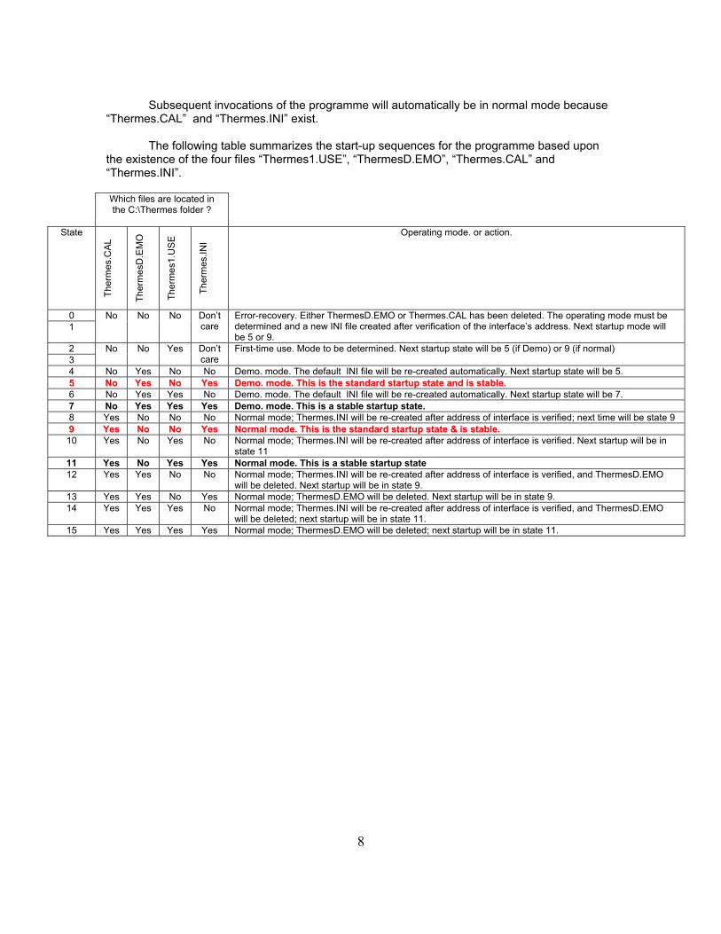
The following table summarizes the start-up sequences for the programme based upon the existence of the four files “Thermes1.USE”, “ThermesD.EMO”, “Thermes.CAL” and “Thermes.INI”.
Which files are located in the C:\Thermes folder ?
State
The
rmes
.CA
L
The
rmes
D.E
MO
The
rmes
1.U
SE
The
rmes
.INI
Operating mode. or action.
0 No
No No Don’t care
Error-recovery. Either ThermesD.EMO or Thermes.CAL has been deleted. The operating mode must be determined and a new INI file created after verification of the interface’s address. Next startup mode will be 5 or 9.
1
2 No
No Yes Don’t care
First-time use. Mode to be determined. Next startup state will be 5 (if Demo) or 9 (if normal) 3 4 No Yes No No Demo. mode. The default INI file will be re-created automatically. Next startup state will be 5. 5 No Yes No Yes Demo. mode. This is the standard startup state and is stable. 6 No Yes Yes No Demo. mode. The default INI file will be re-created automatically. Next startup state will be 7. 7 No Yes Yes Yes Demo. mode. This is a stable startup state. 8 Yes No No No Normal mode; Thermes.INI will be re-created after address of interface is verified; next time will be state 9 9 Yes No No Yes Normal mode. This is the standard startup state & is stable.
10 Yes No Yes No Normal mode; Thermes.INI will be re-created after address of interface is verified. Next startup will be in state 11
11 Yes No Yes Yes Normal mode. This is a stable startup state 12 Yes Yes No No Normal mode; Thermes.INI will be re-created after address of interface is verified, and ThermesD.EMO
will be deleted. Next startup will be in state 9. 13 Yes Yes No Yes Normal mode; ThermesD.EMO will be deleted. Next startup will be in state 9. 14 Yes Yes Yes No Normal mode; Thermes.INI will be re-created after address of interface is verified, and ThermesD.EMO
will be deleted; next startup will be in state 11. 15 Yes Yes Yes Yes Normal mode; ThermesD.EMO will be deleted; next startup will be in state 11.
9
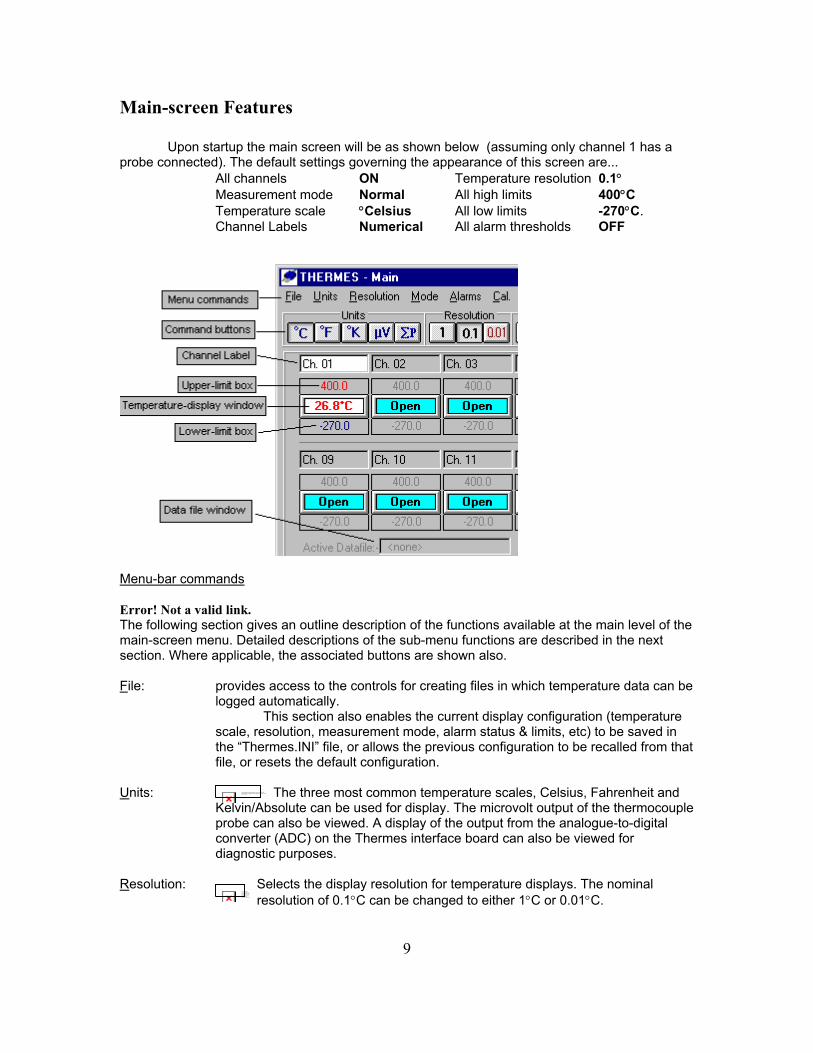
Main-screen Features
Upon startup the main screen will be as shown below (assuming only channel 1 has a probe connected). The default settings governing the appearance of this screen are...
All channels ON Temperature resolution 0.1 Measurement mode Normal All high limits 400C Temperature scale Celsius All low limits -270C. Channel Labels Numerical All alarm thresholds OFF
Menu-bar commands Error! Not a valid link. The following section gives an outline description of the functions available at the main level of the main-screen menu. Detailed descriptions of the sub-menu functions are described in the next section. Where applicable, the associated buttons are shown also. File: provides access to the controls for creating files in which temperature data can be
logged automatically. This section also enables the current display configuration (temperature
scale, resolution, measurement mode, alarm status & limits, etc) to be saved in the “Thermes.INI” file, or allows the previous configuration to be recalled from that file, or resets the default configuration.
Units: The three most common temperature scales, Celsius, Fahrenheit and
Kelvin/Absolute can be used for display. The microvolt output of the thermocouple probe can also be viewed. A display of the output from the analogue-to-digital converter (ADC) on the Thermes interface board can also be viewed for diagnostic purposes.
Resolution: Selects the display resolution for temperature displays. The nominal
resolution of 0.1C can be changed to either 1C or 0.01C. The linked image cannot be displayed. The file may have been mov ed, renamed, or deleted. Verify that the link points to the correct file and location .
The linked image cannot be displayed. The file may have been mov ed, renamed, or deleted. Verify that the link points to the correct file and location.
10
NOTE: Physitemp Instruments Inc. manufactures “medical-grade” probes which are accurate to 0.1C in the physiological range. The use of the 0.01C resolution option does not increase the accuracy of measurement, just the resolution.
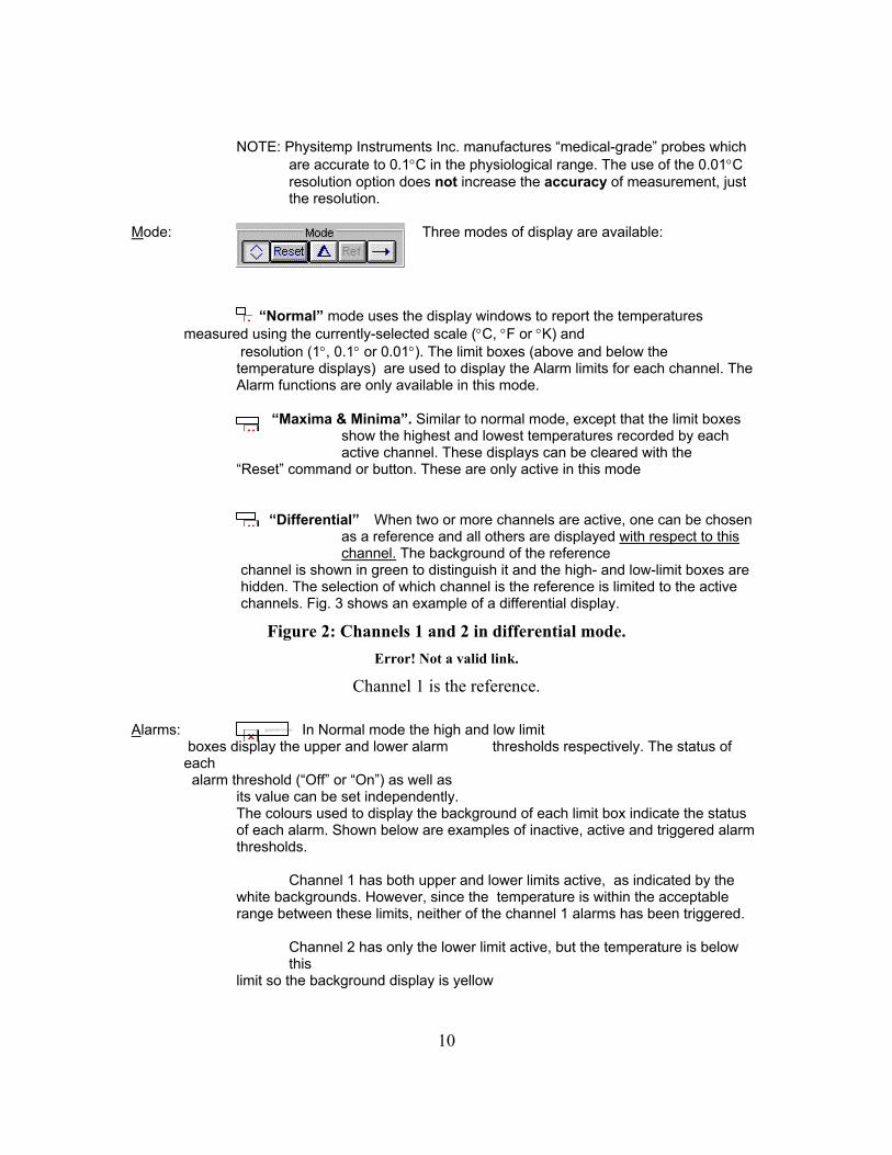
Mode: Three modes of display are available:
“Normal” mode uses the display windows to report the temperatures measured using the currently-selected scale (C, F or K) and
resolution (1, 0.1 or 0.01). The limit boxes (above and below the temperature displays) are used to display the Alarm limits for each channel. The Alarm functions are only available in this mode.
“Maxima & Minima”. Similar to normal mode, except that the limit boxes show the highest and lowest temperatures recorded by each active channel. These displays can be cleared with the
“Reset” command or button. These are only active in this mode
“Differential” When two or more channels are active, one can be chosen as a reference and all others are displayed with respect to this channel. The background of the reference
channel is shown in green to distinguish it and the high- and low-limit boxes are hidden. The selection of which channel is the reference is limited to the active channels. Fig. 3 shows an example of a differential display.
Figure 2: Channels 1 and 2 in differential mode.
Error! Not a valid link.
Channel 1 is the reference.
Alarms: In Normal mode the high and low limit boxes display the upper and lower alarm thresholds respectively. The status of
each alarm threshold (“Off” or “On”) as well as
its value can be set independently. The colours used to display the background of each limit box indicate the status of each alarm. Shown below are examples of inactive, active and triggered alarm thresholds. Channel 1 has both upper and lower limits active, as indicated by the white backgrounds. However, since the temperature is within the acceptable range between these limits, neither of the channel 1 alarms has been triggered. Channel 2 has only the lower limit active, but the temperature is below
this limit so the background display is yellow
The linked image cannot be displayed. The file may have been mov ed, renamed, or deleted. Verify that the link points to the correct file and location.

11
Figure 3 : Alarm-threshold displays
Error! Not a valid link. Cal: The calibration parameters associated with the Thermes system can be accessed
via this command, which will open a extension of the main screen as shown below.
Figure 4 : The "Cal" Window
Error! Not a valid link. The Cal. window is divided into two sections. The larger of the two, to the right, is a display of system constants and variables which may not be changed by the user. The first four, ADC Offset, Amp. I/P Offset, Amplifier Gain and HRO voltage, are functions of the hardware. There should be little (if any) change in these values. Only the last two ( CJR voltage and CJR temp, the latter of which is derived directly from the former) will change according to variations in ambient temperature.
The smaller section of the window, to the left, gives access to the system parameters which CAN be adjusted. Three are related directly to the temperature displays (ZOS – the zero-offset correction, POS and NEG – the positive and negative span corrections), and two control the accuracy of the system’s ability to determine ambient temperature.
Only one of these parameters can be adjusted at a time. This is accomplished with the double-arrowhead “spin” button. Note, however, that access to these adjustments is restricted. The ZOS value cannot be modified unless then temperature on channel 1 is within the range 1C. If the temperature is above this range then only POS is accessible; if it is below then only NEG is accessible. R0 is always accessible and “alpha” is a factory-adjustable value only.
NOTE: IT IS STRONGLY RECCOMMENDED THAT NO ATTEMPT TO BE
MADE TO CHANGE THESE VALUES WITHOUT FIRST CONSULTING PHYSITEMP INSTRUMENTS INC.
Averages: The temperature shown in the main-screen displays can be “filtered” using a
simple averaging function of the last n readings, where n can vary between 1 and 10. This is useful when there is significant “noise”, or variation between successive readings. The higher the value of n, the more stable the reading will be. Note, however, that in 16-channel systems, the more channels you have active, the slower the display-update rate will become. Examples are shown below.
Number of
active channels Averaging sample
size (n) Measurements
between display update
1 1 1 1 10 10 16 1 16 16 10 160
The Averaging function is also used by the programme’s self-calibration
routine. This occurs once every ten seconds and each of the parameters
12
The linked image cannot be displayed. The file may have been moved, renamed, or deleted. Verify that the link points to the correct file and location.
displayed in the Cal. window is updated at that time. The default sample size for the system calibration averaging function is 5 samples (as indicated by the lowest line of values in the Cal. window’s grid). The line above this shows the output of the ADC corresponding to each of the parameters. This is a dimension-less measurement – it is the decimal equivalent of the binary output of the ADC.
On the top line of the Cal. Window grid are the current values of the calibration parameters, expressed in the associated units. Note that ADC offset and Amplifier Gain are also dimensionless.
Setup: Labels In many applications - especially those involving measurement of
multiple inputs - it is often useful to identify the probes by their location or type rather than by channel numbers. These labels can be edited from the "Labels" section of the "Channels" command on the menu bar.
The names assigned to the channels, as displayed in the
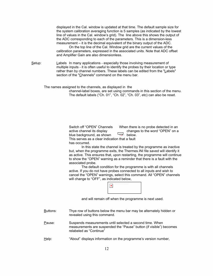
channel-label boxes, are set using commands in this section of the menu. The default labels (“Ch. 01”, “Ch. 02”, “Ch. 03”, etc) can also be reset. Switch off “OPEN” Channels When there is no probe detected in an active channel its display changes to the word “OPEN” on a blue background, as shown below. This serves as a clear indication that a fault has occurred. In this state the channel is treated by the programme as inactive but, when the programme exits, the Thermes.INI file saved will identify it as active. This ensures that, upon restarting, the programme will continue to show the “OPEN” warning as a reminder that there is a fault with the associated probe. The default condition for the programme is with all channels active. If you do not have probes connected to all inputs and wish to cancel the “OPEN” warnings, select this command. All “OPEN” channels will change to “OFF”, as indicated below,
and will remain off when the programme is next used.
Buttons: Thye row of buttons below the menu bar may be alternately hidden or
revealed using this command. Pause: Suspends measurements until selected a second time. When
measurements are suspended the “Pause” button (if visible”) becomes relabeled as “Continue”
Help: “About” displays information on the programme’s version number,
The linked image cannot …
13
Physitemp Instruments’ copyright, and technical-support contacts. “System Info.” shows the identifying characteristics of your system and also provides access to the line-supply-frequency interference-rejection selector. This allows for optimum performance with both 50Hz and 60Hz supplies.
Test: This is a low-level diagnostics routine used for troubleshooting the Thermes hardware when a fault is suspected. It is not required during normal operation. If your Thermes system is not working correctly please contact our technical support department before attempting any troubleshooting with this feature.
Video Overlay: Temperatures and (optionally) time can be displayed on a black screen.
This feature is intended for use with a scan converter to allow temperature data and a video image to be mixed and recorded.
The button bar is divided into four areas that duplicate the commands available from the four identically-named first-level commands on the menu bar: Units, Resolution, Mode and Alarms. Refer to section (#.#) for a complete description of these commands. Channel Labels
In many applications - especially those involving measurement of multiple inputs - it is often useful to identify the probes by their location or type rather than by channel numbers. These labels can be edited from the "Labels" section of the "Channels" command on the menu bar. High- and Low-alarm limits
In the normal measurement mode the programme can be set to watch for out-of-range temperatures on any active channel. The upper and lower limits of the range for each channel are displayed in these boxes. Monitoring of any threshold can be activated and suspended by clicking on the associated Alarm-limit display. (Refer to section #.# for more details on the alarms feature).
In the "Maxima & Minima" mode, these boxes are used to capture the highest and lowest temperatures measured on each channel. (See section #.#) Temperature Displays
Individual channels are turned on and off by clicking the corresponding temperature-display box. When there is no probe connected to that channel's input socket, however, the programme will deactivate the channel and print "Open" in the temperature-display box. Datafile Identification
When data is being recorded in a datafile, its name is displayed in this area.(Refer to section #.# for more details on creating Thermes datafiles
Menu Bar Commands
14
Shown below is an hierarchical listing of all of the commands accessible from the menu bar, at all levels. This is followed, in the successive pages, by an alphabetical summary of the commands. File ............................ Save Configuration
Load Configuration Default Configuration Open datafile Fast-open "THERMES.TDF" Timing Options Comments... Edit Comment List Data Formats.................................................................... Insert Header
Format as NUMBERS Format as TEXT Show time since Midnight Show time from file creation Show time as "HH:MM:SS" Enable “Fast-pen” of Thermes.TDF Overwrite old data
Close Datafile Exit
Units...........................Celsius Fahrenheit Absolute (Kelvin) Voltage Pulse Total
Resolution....................1 degree 0.1 degree 0.01 degree
Mode...........................Maxima and Minima Reset Differential with respect to... Normal
Alarms Switch all Alarms ON Restore Previous alarm thresholds Switch all alarms OFF Set Alarm Thresholds Switch the Beep ON/OFF
Cal. Averages......................Channel-temperature data
System-calibration data.......................................................Set sample size Restart
Setup............................Labels...................................................................................Assign Custom Labels Reset Channel Labels to 01...16 Instructions
Switch off "OPEN" Channels Buttons Pause Help.............................About
System Info Test Video Overlay..............Show
Setup Details
What the commands do Alarms : RESTORE Previous Alarm Thresholds
The selection of alarm thresholds which are active when either of the "Switch all alarms…" commands is issued is stored. It may be recalled using this command. Note that this option is not enabled when the programme first loads since there is no "Previous" state at that time and that the equivalent on-screen button in the "Alarms" group is simply labeled "Old".
15
Alarms: Set Alarm Thresholds
Displays instructions for setting the alarm thresholds of each channel. Three methods are available; text entry, drag-and-drop and Spin-up/down. Use the first to specify an alarm-threshold temperature directly using keyboard input of numerals, the decimal point and + or -. Use the second to replicate threshold settings from one active channel to another. Use the third to make small changes to an existing threshold. The equivalent on-screen button in the "Alarms" group is labeled "Set". Alarms : Switch all alarms OFF
Switches all threshold checking off. The temperatures of all channels are displayed normally but are not compared to the alarm-threshold limits. The background colour of the threshold-display boxes changes to grey. The "RESTORE Previous alarm thresholds" option will become active. This command also affects the alarm thresholds of disabled channels (indicated by "OFF" or "OPEN"); when they are re-enabled their alarm-thresholds will be inactive. This option is disabled if there are no active alarm thresholds. The equivalent on-screen button in the "Alarms" group is labeled "Off". Alarms : Switch all alarms ON
Switches all threshold checking on. The background colour of all active channels' threshold-display boxes changes to white until the measured temperature crosses that threshold
at which point it becomes yellow until all temperatures are within the band defined by the thresholds. This command also affects disabled channels (indicated by "OFF" or "OPEN"); when they are re-enabled their alarm-thresholds will be active. This option is disabled if all alarm thresholds are already active. The equivalent on-screen button in the "Alarms" group is labeled "On". Alarms : Switch the "Beep" ON
In addition to the visual indication of out-of-range temperatures provided by the yellow backgrounds of the corresponding threshold-display boxes, you may wish to use the computer's "Beep" function as an audible warning. When activated the beep will sound at half-second
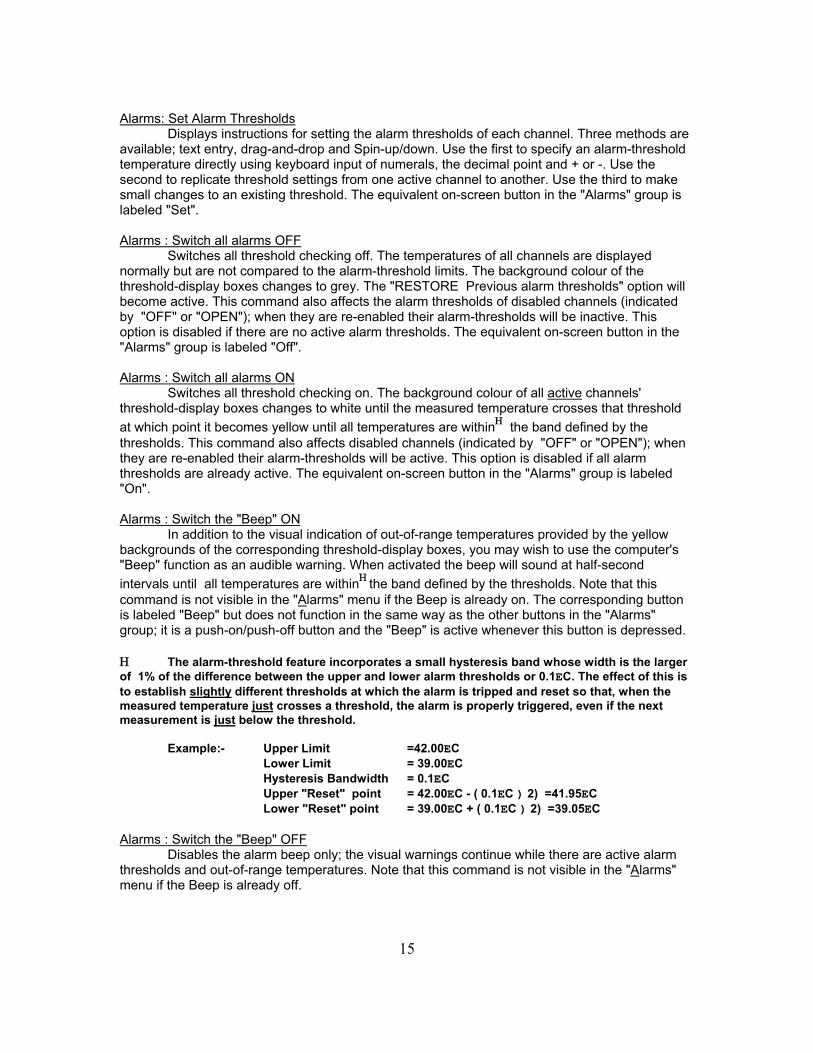
intervals until all temperatures are within the band defined by the thresholds. Note that this command is not visible in the "Alarms" menu if the Beep is already on. The corresponding button is labeled "Beep" but does not function in the same way as the other buttons in the "Alarms" group; it is a push-on/push-off button and the "Beep" is active whenever this button is depressed. The alarm-threshold feature incorporates a small hysteresis band whose width is the larger of 1% of the difference between the upper and lower alarm thresholds or 0.1EC. The effect of this is to establish slightly different thresholds at which the alarm is tripped and reset so that, when the measured temperature just crosses a threshold, the alarm is properly triggered, even if the next measurement is just below the threshold.
Example:- Upper Limit =42.00EC
Lower Limit = 39.00EC Hysteresis Bandwidth = 0.1EC Upper "Reset" point = 42.00EC - ( 0.1EC ) 2) =41.95EC Lower "Reset" point = 39.00EC + ( 0.1EC ) 2) =39.05EC
Alarms : Switch the "Beep" OFF
Disables the alarm beep only; the visual warnings continue while there are active alarm thresholds and out-of-range temperatures. Note that this command is not visible in the "Alarms" menu if the Beep is already off.

16
Averages : Channel-temperature Data Displays a slider control indicating the number of consecutive measurements of each
channel's temperature which are being averaged to yield the displayed temperature. Move the slider to the value desired (between 1 and 10) and press "OK", or just press cancel to keep the current value. Note that this is a "running" average of the last ndat measurements and yields a result after each measurement rather than an average updated only after ndat measurements. Averages : System-calibration Data : Restart
Resets to "1" the size of the buffer holding the previous nsys system-calibration samples. The buffer then expands with each self-calibration until it reaches the current value. (The effect and progress of this function can be observed if the "Cal" window is open; the calibration parameters and number of samples in the buffer are printed in blue text until the buffer is full when they are printed in black). During normal operation this function is unlikely to be required. If the cable linking the interface board to the input adaptor is dislodged , however, the nsys buffer may be loaded with invalid data. This will continue to corrupt the measurements even after the connection is re-established until a complete cycle of nsys samples have been obtained. To avoid this, the Restart command is used to "purge" the buffer. Averages : System-calibration Data : Set Sample Size
Displays a slider control indicating the number of consecutive measurements of system-calibration parameters which are being averaged to determine the current calibration status. Move the slider to the value desired (between 1 and 10) and press "OK", or just press cancel to keep the current value. Note that this is a "running" average of the last nsys measurements and yields a result after each measurement rather than an average updated only after nsys measurements. (For more information on system calibration, refer to the "Cal" section). Buttons
Reveals or hides the row of function buttons across the top of the screen. All of these functions are accessible from the menu bar, so hiding the buttons simply reduces "screen clutter". Cal. NOTE:- This is a "real-time" diagnostic feature and incorrect use can affect the accuracy of the temperature measurements. For this reason it is suggested that the Calibration Window be left closed during normal operation of the progamme.
Displays the status of system-calibration measurements. At approximately ten-second intervals the system will perform a series of self-calibration checks. These ensure that the programme accurately tracks the temperature of the reference-junction array inside the input adaptor and maintains measurement accuracy. Five parameters are measured and the results averaged according to the sample size specified in the "Averages : System-calibration Data : Set Sample Size" section. These are displayed in the grid under the following headings... ADC Offset The interface board uses an analogue-to-digital converter (ADC) whose output is offset by a more-or-less constant value for any given "chip". The programme determines this value by reading the output of the ADC when its inputs are connected to a zero-volt reference. This value is algebraically subtracted from the pulse-total of all successive signal measurements. Amp I/P Offset The instrumentation amplifier used to "boost" the small EMF of the thermocouple also has a characteristic offset. The programme measures this voltage and applies it as a correction factor to readings of the thermocouple voltage.
17
Amplifier Gain The gain of the amplifier is subject to small temperature-dependent variations; it is not constant. The programme derives a value for gain dynamically using, as a reference, a known voltage with greater thermal stability than the amplifier's circuitry). Typical values are between 27 and 28. HROVoltage A known, reference voltage used to "expand" the input range of the ADC and verify its conversion accuracy. Typical values for HRO are between 280 and 300mV CJR Voltage The signal from the cold-junction reference array from which the cold-junction reference temperature is derived. For "typical" room temperatures around 20 degrees Celsius, a CJR voltage value of approximately 280 mV should be observed. CJR Temp. The programme's determination of ambient temperature inside the input adaptor.
This will depend upon ambient-temperature conditions and the time allowed for equilibration. If the input adaptor has been at rest in a temperature-controlled room for several hours, the CJR temperature should be the same as (or very close to) ambient temperature. If the adaptor has just been moved between warm and cool areas, however, the temperature indicated will not necessarily be close to ambient.
The System-calibration routine may also be suspended or run on demand by clicking the "Calibrate" or "Self-Cal. OFF/ON" buttons.
The "Cal" feature also provides access to the settings adjusted during final calibration at the factory. For this reason a number of safeguards have been added to this feature to minimize the chances and effects of accidental changes being made. Specifically: the adjustment-control panel is hidden if channel 1 is not in use; the positive-span adjustment is inaccessible below measured temperatures of 1C; the negative-span adjustment is inaccessible above -1C; the zero-offset control is only accessible for measured temperatures in the range "1C; the "alpha" term is not accessible below ambient temperatures of 30C and R0 is not accessible above this temperature.
If any changes are made to the current settings (Which are stored in the "Thermes.Cal" file copied from Setup-disk 2 to the C:\Thermes sub-directory), a button labeled "Store" will appear which opens a second-level confirmation window warning that system-specific calibration data is about to be re-written in the Thermes.Cal file and showing a summary of the old and new values. At this point you may cancel and continue using the existing values, or over-write the old values with the new.
"Disaster recovery" from accidental changes to the calibration file is possible in two ways. When new data is written to Thermes.Cal, the old data is copied to Thermes.CAB. If the data has only been changed once then Thermes.CAB will still contain the original factory-set values. Exit from the programme, delete Thermes.CAL and rename Thermes.CAB as Thermes.CAL. When the programme is restarted the original values will be in use.
If the contents of Thermes.CAL has been changed more than once then there is no guarantee that Thermes.CAB contains the original factory-set data. In this case delete both Thermes.CAL and Thermes.CAB and re-start the programme. It will detect the absence of the calibration file and request that you insert the original setup disk#2 in drive A: from which it will copy the original file. Diagnostics
Suspends measurements and opens a low-level diagnostic window through which individual signals and sub-circuits in the Thermes system can be tested. This feature should only

18
be used if the system appears to be malfunctioning and generally requires the use of several pieces of test equipment typically found in an electronics-test facility. Contact the factory for assistance with this feature. File : Close Datafile
Click on this command to stop saving data and close the datafile in use. This command is only available when a file has already been opened using either the "Open Datafile" or "Fast-open THERMES.TDF" commands. Once the file is closed the command is once again disabled. Note that exiting from the Thermes programme will close any open datafiles.
(A useful short-cut for this command is to double-click the "Active/Pending Datafile" label in the Datafile Identification region of the main screen). File : Comments : Edit Comment List
A list of eight comments can be stored in your "THERMES.INI" file. These can be used as "markers" in the datafile to note the occurrence of events associated with your experimental procedure (such as "Heater Power ON", "Solution flow OFF"...). Click on "Edit comment list" to view the current list of comments and make changes.
When a datafile is open these comments can be inserted at any time using by holding
down the <shift> key and pressing one key in the range F1 to F8; the comment number corresponds to the Fn key pressed. The comment will appear on its on line in the datafile, preceded by a time-stamp of the format chosen in the "Options..." File : Data Formats
Formatting and comment options are described and selected from the window opened by this command. "Insert... header....", when enabled, causes the following line of text to be printed as the first line of a datafile when it is opened...
"Thermes datafile created on [mm:dd:yy] at [hh:mm:ss]"
...where [mm:dd:yy] and [hh:mm:ss} represent the usual date and time formats. Selection of the "Format as Numbers" option will reduce the overall size of the file which
may be important when large amounts of data are to be recorded. This option will also simplify the process of importing the datafile into spreadsheet and graphical packages. Note that this option disables the Show time as "HH:MM:SS" option since this is a text string. Times must either be stored based upon the computer's internal "Timer" function ("Show Time since Midnight") or lapsed time (" Show time from File creation").
Use of the "Format as Text" option will render the file more readable than will the "Format as Numbers" option since each piece of data is formatted as a fixed-length string with polarity and leading spaces as necessary. This produces a columnar format and makes the trend for any given channel easy to see. Selection of the "Text" option constrains the time-stamp at the beginning of each reading to the "HH:MM:SS" format. Note, however, that a file in this format will not be directly importable into a spreadsheet cell without some additional formatting. This will involve the conversion of text into its numerical equivalent throughout the use of a conversion function such as "Val" or "@Value". (Check your spreadsheet documentation for details).
The option to enable the fast-opening of the "THERMES.TDF" file is controlled from this screen. Removing the "X" from the box disables this feature.
Since the same file is always used in conjunction with the Fast-open feature, it would be
easy to activate it, collect data, close it, and then, at some future time, inadvertently re-activate it, thereby over-writing the old data. To prevent this, the file is normally opened in the "Append" mode. This means that new data is added to the end of the old without destroying it. You may
19
disable this feature; old data will then be lost.
Temperatures in the datafile are normally stored in Celsius. You may select Fahrenheit using the boxes at the top right corner of the Data formats' screen. This selection, and the selection of screen-display units are independent File : Default Configuration
Select this option to return the main-screen to its start-up configuration thus...
All channels ON Temperature resolution 0.1 Measurement mode Normal All high limits 400C Temperature scale Celsius All low limits -270C. Channel Labels Numerical All alarm thresholds OFF
Note that channels without probes connected will be turned off and identified as "Open"
by the programme. If no further changes are made before exiting from the programme, the default configuration will be saved in "THERMES.INI" and re-loaded when the programme is next used. Clicking on "Load Configuration" will restore the last configuration saved in "THERMES.INI". Use this command to avoid losing your settings following accidental selection of the "Default Configuration" command. File : Exit
The main exit routine for the programme. Note that this command may be accessed at any time using the shortcut "Ctrl-X". Any open datafile will be closed and the existing configuration will be saved in "Thermes.INI". File : Fast-open "THERMES.TDF"
A dedicated datafile called "Thermes.TDF" may be opened when the <F12> key is pressed if this option is selected. This is useful when the recording of data is to begin without the delay associated with selecting a name for a datafile. Note that this option must be enabled from within the "File - Options" menu. See section #.# for more details.
NOTE:- It is recommended that data collected in this file be copied to one with a name which is more meaningful to your application. In addition to serving as a useful remainder of the file's contents when you are browsing through a sub-directory (or folder), this practice ensures that the data cannot be destroyed should the file be re-opened with the over-write protection deactivated. (Refer to the "File - Data Formats" section). File : Load Configuration
When the programme is loaded it will search for a configuration file called "Thermes.INI" in the "C:\Thermes" subdirectory. This contains a description of the user-selected parameters at the time the programme was last closed. If changes have been made to the number and channel-assignment of thermocouple probes connected to the input adaptor, some previously-active channels may now be identified as "Open". If, on the other hand, if previously open or inactive channels are now in use it will be necessary to switch them on by clicking on their temperature-display panels.
Note that the current configuration is not saved in the Thermes.INI file until the programme is closed, or the "File : Save Configuration" command is used. File : Open Datafile
Data measured by the Thermes system may be saved in a datafile for subsequent data processing or presentation by any standard spreadsheet or graphical package. Click on "Open a
20
Datafile" to open a dialog box for specifying the name and location of the file to be created. (Note the use of the default extension ".TDF" for Thermes Data Files).
Click this dialog box's "OK" button to begin saving data. (Refer to the sections on "File: Timing Options..." and "File : Data Formats" for a full description of the format and frequency of data acquisition). File : Save Configuration
This command saves the current state of the user-definable display, formatting and alarm-threshold options in "Thermes.INI". Note that this procedure is performed automatically upon exit from the programme. File :Timing Options
Temperature readings displayed on the screen are updated at the rate of approximately 16 readings per second; this rate varies with processor type and speed, available memory and the demands of other tasks in the Windows environment. This command opens a window from which the period of a separate timer - used to control the rate at which data is sent to a datafile - may be set in one-second intervals from 1 second to 24 hours. The hours, minutes and seconds may all be set independently using the associated double-arrowheaded "spin" buttons. When a datafile is open and this timer "ticks", data on all active channels will be recorded in Celsius, with 0.01 resolution. The default value of this feature is 10 seconds.
Note:- Because the update rate is being specified to the nearest second, the actual display of time in the datafile may sometimes "slip" and be shown as one second less or one second more than the specified interval. Also, in older computer systems (486-based), and those with minimal amounts of RAM or multiple active applications using large amounts of system resources, the CPU may not be free to service the file-update timer at the precise moment it issues a request for service.
If the datafile-update interval is set to zero ("00:00:00"), the output-to file option will be disabled.
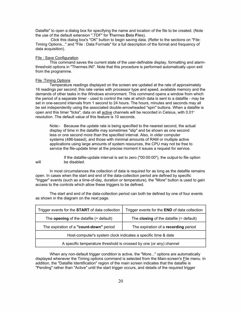
In most circumstances the collection of data is required for as long as the datafile remains open. In cases when the start and end of the data-collection period are defined by specific "trigger" events (such as a time-of-day, duration or temperature), the "More" button is used to gain access to the controls which allow these triggers to be defined.
The start and end of the data-collection period can both be defined by one of four events as shown in the diagram on the next page.
Trigger events for the START of data collection Trigger events for the END of data collection
The opening of the datafile (= default) The closing of the datafile (= default)
The expiration of a "count-down" period The expiration of a recording period
Host-computer's system clock indicates a specific time & date
A specific temperature threshold is crossed by one (or any) channel
When any non-default trigger condition is active, the "More..." options are automatically
displayed whenever the Timing options command is selected from the Main-screen's File menu. In addition, the "Datafile Identification" region of the main screen indicates that the datafile is "Pending" rather than "Active" until the start trigger occurs, and details of the required trigger
21
event are displayed to the right of the filename display area.
IMPORTANT:- The data-trigger events apply to files opened with the "File - Open a datafile" command ONLY. "Thermes.TDF", when activated using the "File- Fast-open THERMES.TDF" command, (or the <F12> key), is NOT affected by these triggers. Help : About
Displays the programme identification, version number and technical support details. Help :System Information
Displays system constants stored in the "Thermes.CAL" file. These are unique to the input adaptor in use. Mode: Differential with respect to Channel...
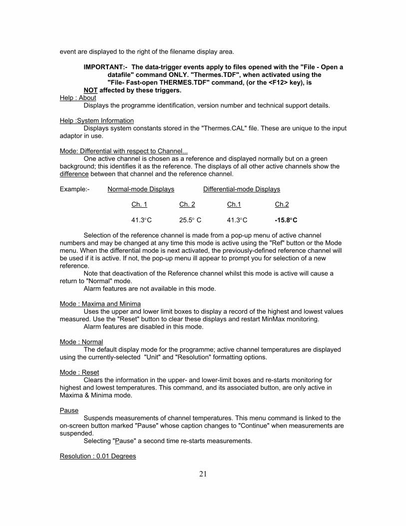
One active channel is chosen as a reference and displayed normally but on a green background; this identifies it as the reference. The displays of all other active channels show the difference between that channel and the reference channel. Example:- Normal-mode Displays Differential-mode Displays
Ch. 1 Ch. 2 Ch.1 Ch.2
41.3C 25.5 C 41.3C -15.8C
Selection of the reference channel is made from a pop-up menu of active channel numbers and may be changed at any time this mode is active using the "Ref" button or the Mode menu. When the differential mode is next activated, the previously-defined reference channel will be used if it is active. If not, the pop-up menu ill appear to prompt you for selection of a new reference.
Note that deactivation of the Reference channel whilst this mode is active will cause a return to "Normal" mode.
Alarm features are not available in this mode. Mode : Maxima and Minima
Uses the upper and lower limit boxes to display a record of the highest and lowest values measured. Use the "Reset" button to clear these displays and restart MinMax monitoring.
Alarm features are disabled in this mode. Mode : Normal
The default display mode for the programme; active channel temperatures are displayed using the currently-selected "Unit" and "Resolution" formatting options. Mode : Reset
Clears the information in the upper- and lower-limit boxes and re-starts monitoring for highest and lowest temperatures. This command, and its associated button, are only active in Maxima & Minima mode. Pause
Suspends measurements of channel temperatures. This menu command is linked to the on-screen button marked "Pause" whose caption changes to "Continue" when measurements are suspended.
Selecting "Pause" a second time re-starts measurements. Resolution : 0.01 Degrees
22
Channel temperatures are displayed to one hundredth of a degree.
Note:- The Thermes System Accuracy is not 0.01E; this display is intended to provide an indication of the sub-tenth-degree trend only. Resolution : 0.1 Degrees
Channel temperatures are displayed to one hundredth of a degree. This is the default resolution. Resolution : 1 Degree
Channel temperatures are displayed to one degree. Setup : Labels : Assign Custom Labels
The start-up condition for the channel-labels is the channel's number, from 1 to 16. Use this option to change the channel's label to something more descriptive related to the probe's type, position or function.
Channel 1's label will be accessible when this option is first clicked - you may also open the label editor at a specific channel by double-clicking its label box.
Enter the name to be used for the currently-selected channel then press "Enter" to move to the next channel in sequence, or click on a specific channel's label box to edit it out of sequence.
Press "Esc" or double-click a label box to finish editing. Setup :Labels : Instructions
Displays a summary of the instructions for editing channel labels Setup :Labels : Reset Channel Labels to 01...16
Removes the user-defined channel labels and replaces them with channel numbers. (If the custom labels were retrieved from or stored in the "Thermes.INI" file prior to this command they may be recalled using the File : Load Configuration" option). Setup :Switch Open Channels OFF
Clears the word "Open" anf the blue back-ground from channels which have no probe inserted, and replaces this with "OFF" against a dark grey background. Units : Absolute (Kelvin)
Converts the displays of channel temperatures to the "thermodynamic" scale using an offset of 273.16E with respect to the Celsius scale. Units : Celsius
Displays channel temperatures in Celsius or "Centigrade". Note that the "CJR Temp." indication of the Cal. window which is always displayed in Celsius. Units : Fahrenheit
Displays channel temperatures in Fahrenheit. Units : Pulse Total
Indicates the number of data pulse received from the ADC in response to the amplified signal from the thermocouple probes. Alarm features are disabled when this scale is selected, and resolution is fixed at "1". Units : Voltage
Displays the output, in microvolts, of the thermocouple probes. Alarm features are disabled when this scale is selected, and resolution is fixed at "1".
23
Video Overlay : Details
Displays instructions for the use of the video-overlay option which was developed specifically for use with image-mixing systems and allows temperatures to be placed over, or adjacent to, features in an image from a video camera for subsequent recording on videotape. Without the camera, image mixer and video monitor connected this display mode is of little use other than to provide large-text displays of temperature and time on an otherwise blank screen.
Video Overlay : Setup
Font, text size and text color for the video-overlay mode are specified from the window opened with this command. Changes are sometimes necessary to improve the visibility of the temperatures in a video scene according to the background colours. Video Overlay : Show
Activates the video-overlay display mode. (This may also be called using the shortcut key combination "Ctrl-O". Optical Isolation
The "standard" version of the Thermes interface board is supplied with three 16-pin DIP shunts installed in positions SKT1, SKT2 and SKT3. These link the measurement and conversion circuitry directly to the computer's data and control buses and power supplies.
Under certain circumstances it becomes necessary to provide complete isolation of this circuitry - and the adaptor and probes connected to it - from the computer and system ground. A typical example is the measurement of the temperature of an electrically-conductive solution being heated by an immersion heater; leakage currents from the heater through the probe and Thermes board can produce erratic or inaccurate measurements.
In such cases the Thermes system can either be ordered with the optical-isolation feature installed at the factory, or the optical-isolation kit can be added to the Thermes board in the field.
When factory-installation of the " -ISO" option is chosen, the shunts in the interface board are removed and the optical-isolation board is connected in their place. This board is the same size as the main interface board and "breaks" the digital-signal and power lines. Data and power are carried across this isolation gap using optical and magnetic techniques respectively. In the case of the data lines, the electrical "ones" and "zeroes" are translated into pulses of light inside opto-isolators. The power is transferred via a "DC-to-DC Converter" - essentially a compact transformer.
Field installation of the opto-isolator board
WARNING: - The Thermes interface board and optical-isolation board contain electrical devices which can easily be damaged by static electricity. When handing these boards you should do so by the edges only. It is recommended that the installation be performed in static-free or static-controlled conditions to reduce the possibility of damage due to electrostatic discharge. If there are no static-control facilities available, use one hand to insert the board and keep the other in contact with a grounded surface.
Switch off the computer, disconnect the power and remove the cover. Remove the Thermes interface board from the expansion slot and locate the three 16-pin shunts in positions
24
SKT1, SKT2 and SKT3. (These are position on the long central axis of the board).
Carefully remove these shunts. They will not be used again, but it is recommended that you save them in case it is ever necessary to run the Thermes system in non-isolated mode in the future.
Locate the internally-threaded hexagonal spacer and two screws supplied with the opto-isolator board. Use one screw to attach the spacer to the interface board in the mounting hole just above the identification marking "8-18010", printed in white.
Locate the two "snap-in" spacers supplied with the opto-isolator board and push them into the two holes in the corners of the interface board furthest from the metal mounting bracket.
Remove the opto-isolator board from its static-protective bag. There are three sets of sixteen gold-plated pins on the underside. Remove the protective foam from these pins and line up these pins with the corresponding socket strips on the interface board.
GENTLY push the boards together until the pins and spacers snap together. Secure the assembly with the second screw through the hole in the opto-isolator board.
Re-install the Thermes assembly in the expansion slot and tighten the mounting screw which holds it in the computer chassis.
NOTE:- The addition of the opto-isolator board requires that two expansion slots be allocated to the Thermes system, even though only one connector is in use. This may require that a different slot be used, or that other boards in the computer's expansion-slot area be moved.
Replace the computer cover, re-attach the power cable and switch on. The Thermes programme should operate as before. Please contact Physitemp's Engineering-support department (973-779-5577 x 16 )if you encounter any problems or are unsure of any part of this procedure. Upgrading from the single-channel system.
Located on the Thermes interface board are eight "DIP" switches. Four of these ( 1 - 4) set the logical address used by the board and should not be changed.
The second set (5 - 8) determine whether the interface and programme recognise the
presence of a single-channel adaptor, or the multi-channel version. When a system is purchased with a single-channel adaptor, these four switches are in the "OFF" position. If a sixteen-channel adaptor is to be used these switches must be closed (i.e. set in the "ON" position).
In addition to this hardware change, the calibration file associated with the old single-channel adaptor must be replaced by its counterpart for the sixteen-channel version. This will be supplied with the sixteen-channel adaptor at the time of purchase on a diskette. Copy the file called "THERMES.CAL" to your "C:\THERMES" folder. You will be asked to confirm that you wish to over-write the older version of a file with the same name.
NOTE:- BOTH of these changes must be made. The Thermes programme will warn you if it detects incompatibility between the hardware and software settings.
25
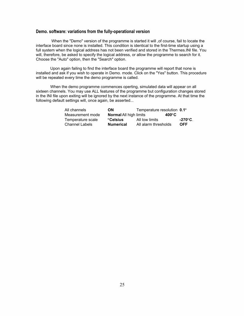
Demo. software: variations from the fully-operational version
When the "Demo" version of the programme is started it will ,of course, fail to locate the interface board since none is installed. This condition is identical to the first-time startup using a full system when the logical address has not been verified and stored in the Thermes.INI file. You will, therefore, be asked to specify the logical address, or allow the programme to search for it. Choose the "Auto" option, then the "Search" option.
Upon again failing to find the interface board the programme will report that none is installed and ask if you wish to operate in Demo. mode. Click on the "Yes" button. This procedure will be repeated every time the demo programme is called.
When the demo programme commences operting, simulated data will appear on all sixteen channels. You may use ALL features of the programme but configuration changes stored in the INI file upon exiting will be ignored by the next instance of the programme. At that time the following default settings will, once again, be asserted...
All channels ON Temperature resolution 0.1 Measurement mode Normal All high limits 400C Temperature scale Celsius All low limits -270C. Channel Labels Numerical All alarm thresholds OFF