phytrex serial e-bert pbr-310c e-bert user … · chapter 1 - system overview ... 3. ensure that...
TRANSCRIPT
Phytrex SERIAL E-BERT
1
PBR-310C E-BERT User Guide All rights reserved
Copyright © 2014, Phytrex Technology Corp. All rights reserved.
Statement of Conditions Phytrex Corp. reserves the right to revise the information in this document without notice.
Phytrex Corp. provides this documentation without warranty of any kind, either implied
or expressed, including, but not limited to, the implied warranties of merchantability and
fitness for a particular purpose. Phytrex Technology Corp. reserves the right to make
changes or improvements in the products and/or the services described in this
documentation at any time.
If there is any software on removable media described in this documentation, it is
furnished under a license agreement included with the product as a separate document or
in the hard copy documentation.
Version 2.3 2014/03
Phytrex SERIAL E-BERT
2
Contents General Safety.......................................................................3
System Specifications............................................................6
Handling Precautions.............................................................6
Chapter 1 - System Overview................................................7
Chapter 2 - System Installation............................................12
Chapter 3 - E-BERT Graphical User Interface (GUI)..........16
Chapter 4 - E-BERT Labview Programming Guide.............20.
Compliance and Certification..............................................34
Software License Agreement...............................................40
Customer Service and Contact Information.........................42

Phytrex SERIAL E-BERT
3
General Safety
Intended Audience This document is intended for trained personnel in either telecommunications or networking environments who have a solid understanding of safety procedures around electricity and lasers. WARNING: ONLY TRAINED AND QUALIFIED PERSONNEL ARE ALLOWED TO OPERATE THIS EQUIPMENT.
Safety on Electricity
Do not perform any action that creates a potential hazard to personnel or makes the
equipment unsafe. Observe the following guidelines when working with any electrical
equipment:
• Carefully examine the entire work area for possible hazards such as wet floors,
ungrounded power extension cables, and missing safety grounds before beginning
work
• Disconnect the power cords from the equipment whenever possible. Make sure
that power cord is readily identifiable and easily reached
• Disconnect all external cables before installing or removing
• Failure to ensure adequate grounding can cause product damage and can make
the product dangerous
• Never install equipment that appears damaged.
• Never position the equipment where it is difficult to operate the disconnecting
device (appliance coupler).
• Use of this equipment in a manner not specified by the manufacture may impair
built-in safety protection mechanisms provided by the equipment.
• The E-BERT system should be used in accordance with local and national
electrical codes.
• The power plug must be connected to a properly wired earth ground outlet
receptacle. An improperly wired power outlet could place hazardous voltages on
accessible metal parts of the chassis.
The E-BERT PBR-310 has electrical and optical ports. Follow appropriate electrostatic
discharge and optical eye safety precautions when using the PBR-310C.
ELECTRICAL CLASS I EQUIPMENT THIS EQUIPMENT MUST BE EARTHED. Power plug must be connected to a properly wired
earth ground outlet. An improperly wired socket outlet could induce hazardous voltages on
accessible metal parts. Use the power cord supplied with the equipment.
ELECTRICAL - AC MAIN CIRCUIT OVERLOADING When installing product, consideration must be given to the accumulative nameplate rating when
connecting the equipment to the AC supply wiring.
ELECTRICAL – AUTOMATIC PRIMARY INPUT VOLTAGE ADJUSTMENT This product will automatically adjust to any voltage between the ranges shown on the datasheet.

Phytrex SERIAL E-BERT
4
Safety Notification
WARNING
1. Always refer to this manual when working near environment which the alert mark show on the left. If operation is performed without heeding the advice in this operation manual, there is a risk of personal injury. In addition, the performance of this equipment may be reduced. Moreover, this alert mark is sometimes used with other marks and descriptions indicating other dangerous.
2. When supplying the power to this equipment, please make sure the 3-pin power cable to 3-pin grounded power outlet is well connected. If a grounded power outlet is not available, before supplying power to the equipment, use a conversion adapter and ground the green wire, or connect the frame ground on rear panel of this equipment to ground. If power is supplied without grounding the equipment, there is risk of receiving a severe or fatal electric shock.
3. This equipment cannot be repaired by user. DO NOT attempt to
open the cabinet or disassemble internal parts without authorization. Only Phytrex well trained service people or staff who get the authorization could service this equipment. In addition, there is a risk of damage to precision parts inside the equipment.
CAUTIONS 1. Before changing the fuse, ALWAYS remove the power cord
from the power outlet and replace the fuses. Always use new fuses of the same type and rating specified on the fuse marking on the rear panel of cabinet.
2. Keep the power supply and cooling fan free of dust.
Clean the power inlet regularly. If dust accumulates around the power pin, there is a risk of fire.
Keep the cooling fan clean and the ventilation holes are not obstructed. If the ventilation is obstructed, the cabinet may over heat.

Phytrex SERIAL E-BERT
5
System Specifications The PBR-310 is intended for indoor controlled environment use only.
Environmental
Acoustic Noise 60 dBA maximum
Temperature Operating: 5o
C to 40o
C
Storage: 0o
C to 70o
C
Relative Humidity Operating, non-condensing
5 to 85% continuous
Storage, non-condensing: 5 to 95%
Electrical
Electrical Rating 100 to 240 VAC, 1.4A, 50/60 Hz
Mains voltage fluctuations ±10%
Transient Transient Overvoltage Category II
Physical
Dimensions (L)375mm X (W)275mm X (H)85mm
Net Weight < 8 Kgw

Phytrex SERIAL E-BERT
6
Handling Precautions
1. The PBR-310 is intended for operation at an ambient temperature of 25 degrees Centigrade.
2. Adequate airflow should be provided to the PBR-310 to maintain the required ambient thermal
conditions.
3. Ensure that the PBR-310 power supply and all equipment used with it have properly earthed ac power
supplies.
4. Standard precautions against electrostatic discharge (ESD) must be followed while handling the
PBR-310. Terminate unused electrical output ports with 50 ohm connected to ground.
5. The PBR-310 must be operated in a dust-free environment. Keep unused ports capped. Particular care
must be taken to ensure that the optical connectors are kept clean. It is recommended that the
connector surfaces and exposed parts be cleaned periodically with lint-free wipes (Texwipes® or
Kimwipe® ) and talcum-free swabs soaked in optical-grade isopropyl alcohol, and then blown dry
with inert dusting gas (Tech Spray® Duster 1671). Do not use freon-based cleaners.
6. Follow ESD precautions when removing or inserting pluggable optics modules. Although the
modules can be removed or installed when the unit is powered up, it is recommended that the System
be powered down for changing optical modules.
7. Use the USB adapter cable provided with the system to connect the serial interface to the standard
USB COM port of a desktop or laptop PC.
Phytrex SERIAL E-BERT
7
Chapter 1 - System Overview
Introduction
The E-BERT PBR-310 is an easy-to-use bit-error-ratio tester. PBR-310 suited for research, development, and
manufacturing environments. The PBR-310 is a very compact unit that incorporates electrical interfaces to a
pattern generator and bit error analyzer. It comes with an intuitive graphical user interface (GUI) and a
comprehensive single screen display.
The E-BERT PBR-310 has been designed to operate with few user-settable parameters and with minimal
training. The System has a built-in clock recovery mechanism that is typically not available in an integrated
form in commercial bit-error-rate testers. The System also has an intelligent data pattern synchronization feature
that automatically initiates pattern synchronization when the data rate is changed or the Analyzer signal is
interrupted.
The PBR-310 records the results of bit-error-rate measurements in a spreadsheet format for analysis and
archiving. No programming knowledge is required to enable the recording feature.
PBR-310 E-BERT Features
The PBR-310 is a versatile unit possessing a wide variety of features summarized below:
All in one BERTS and Eye Diagram Analysis
Bit-Error-Ratio (BER) measurement for NRZ PRBS 27
-1, 29
-1,223
-1, 231
-1
Multi-rate operation covering from 8.5~11.3Gb/s, function is support from
8.5~11.1Gb/s
Full Duplex Dual Differential 100 Ω SMA electrical interface to double the testing
throughput
Built-in clock recovery function from 8.5~11.3Gb/s with 1/64 -rate clock output
Accumulated error count and error ratio statistics
Graphical display of BER and Error Count
Eye Diagram and Mask Test
Histogram and Contour
User programming library for sequential control
Measurement result export option
Phytrex SERIAL E-BERT
8
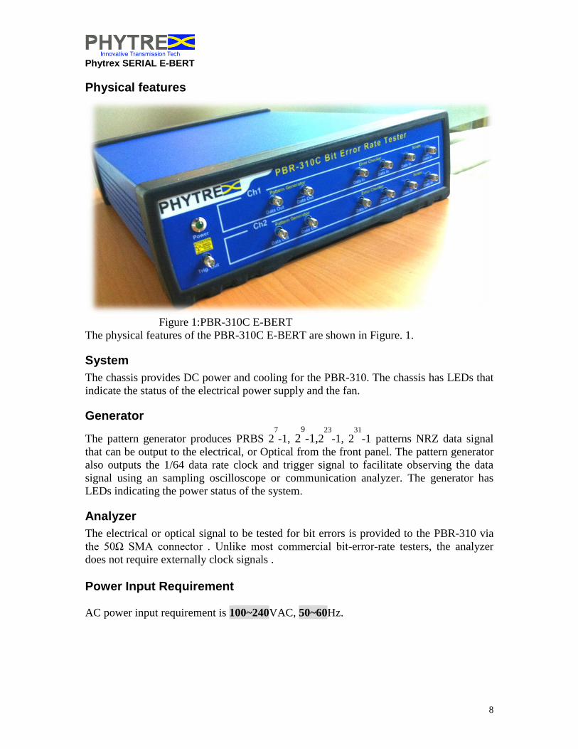
Physical features
Figure 1:PBR-310C E-BERT
The physical features of the PBR-310C E-BERT are shown in Figure. 1.
System
The chassis provides DC power and cooling for the PBR-310. The chassis has LEDs that
indicate the status of the electrical power supply and the fan.
Generator
The pattern generator produces PRBS 27
-1, 29
-1,223
-1, 231
-1 patterns NRZ data signal
that can be output to the electrical, or Optical from the front panel. The pattern generator
also outputs the 1/64 data rate clock and trigger signal to facilitate observing the data
signal using an sampling oscilloscope or communication analyzer. The generator has
LEDs indicating the power status of the system.
Analyzer
The electrical or optical signal to be tested for bit errors is provided to the PBR-310 via
the 50Ω SMA connector . Unlike most commercial bit-error-rate testers, the analyzer
does not require externally clock signals .
Power Input Requirement
AC power input requirement is 100~240VAC, 50~60Hz.

Phytrex SERIAL E-BERT
9
Front Panel
Figure 2: Front Panel Overview
Item Definition
1 Channel 1 Pattern Generator Differential Data Output
2 Channel 2 Pattern Generator Differential Data Output
3 Channel 1 Error Checker Differential Data Input
4 Channel 2 Error Checker Differential Data Input
5 Channel 1 Scope Differential Data Input
6 Channel 2 Scope Differential Data Input
Rear Panel
Figure 3 : Rear Panel Overview
Phytrex SERIAL E-BERT
10
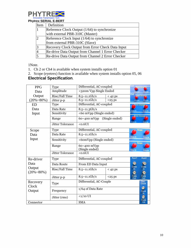
Item Definition
1
Reference Clock Output (1/64) to synchronize
with external PBR-310C (Master)
2 Reference Clock Input (1/64) to synchronize
from external PBR-310C (Slave)
3 Recovery Clock Output from Error Check Data Input
4 Re-drive Data Output from Channel 1 Error Checker
5 Re-drive Data Output from Channel 2 Error Checker
1Note.
1. Ch 2 or Ch4 is available when system installs option 01
2. Scope (eyetrex) function is available when system installs option 05, 06
Electrical Specification.
PPG
Data
Output
(20%~80%)
Type Differential, AC-coupled
Amplitude >320m Vpp Single Ended
Rise/Fall Time 8.5~11.1Gb/s < 42 ps
Jitter p-p 8.5~11.1Gb/s <25 ps
ED
Data
Input
Type Differential, AC-coupled
Data Rate 8.5~11.3Gb/s
Sensitivity <60 mVpp (Single ended)
Range 60~400 mVpp (Single ended)
Jitter Tolerance <0.6UI
Scope
Data
Input
Type Differential, AC-coupled
Data Rate 8.5~11.1Gb/s
Sensitivity <60mVpp (Single ended)
Range 60~400 mVpp (Single ended)
Jitter Tolerance <0.6UI
Re-driver
Data
Output
(20%~80%)
Type Differential, AC-coupled
Data Route From ED Data Input
Rise/Fall Time 8.5~11.1Gb/s < 42 ps
Jitter p-p 8.5~11.1Gb/s <25 ps
Recovery
Clock
Output
Type Differential, AC-Couple
Frequency 1/64 of Data Rate
Jitter (rms) <1/10 UI
Connector SMA

Phytrex SERIAL E-BERT
11
PC interface
An USB/Virtual COM serial communication interface is provided through an USB
connector jack on the front panel. Use the USB cable provided with the System to
connect the unit to the desktop or laptop PC. There is no hardware flow control provided
on the PBR-310’s serial interface. The USB/COM port settings are shown in Chapter 2.
No other special serial port settings (such as FIFO buffer sizes) are required on the
computer (PC) running the E-BERT GUI.
Figure 4: USB Connector on rear panel
Figure 5: Virtual COM display on Device Manger in Windows Control Panel

Phytrex SERIAL E-BERT
12
Chapter 2 - System Installation
Introduction
This chapter provides information necessary for the proper installation of the PBR-310.
Hardware installation
The PBR-310C package has the following items:
Mainframe in a chassis
DC to 18GHz Broadband Terminator
USB Jack to Jack cable for Serial interface to PC terminal
AC power cable (grounded)
Software installation disk and System User Manual
The PBR-310’s power supply can be connected to any AC outlet with a rating of 100-240
VAC / 50-60 Hz. It draws a maximum of 0.5A. Use of conditioned AC power is
recommended.
Following item is the operation procedure
I. Place the System on a tabletop or similar flat surface. It is recommended that
the air in the vicinity of the System be relatively free of dust and heavy
particulates. Excessive dust can damage fan and other internal components,
and cause overheating.
II. Connect the terminator on unused channel.
III. Connect the USB connector of the serial interface cable to the desktop or
laptop PC
IV. to launch the E-BERT GUI (Graphical User Interface) will be run. Connect
the USB connector of the cable to the E-BERT rear panel.
V. Use the AC power cable included with the System to connect the unit to the
AC power outlet. To avoid the chance of electric shock, attach the power cord
to the E-BERT chassis before inserting the plug into the AC power outlet.
Turn the AC power on . The front panel LEDs should glow steadily.

Phytrex SERIAL E-BERT
13
Software Installation
The PBR-310 GUI is a LabVIEW application operating under Microsoft Windows XP
and Windows 7 operating systems1
. The E-BERT GUI needs LabVIEW 7.1 Run-Time
Engine to be installed on the PC connected to the E-BERT System. The executable
versions of the application and the Run-Time Engine are provided with the installation
disk
Installing USB Driver
Figure 6: USB/COM Driver installation Folder
1. Power on your computer and make sure that the USB port is enabled and
working properly.
2. During installation , please don’t link USB-Serial cable with your computer .
3. Double click ‘CP210x_VCP_Win_XP_S2K3_Vista_7.exe ’ , then it will start
installation (Figure 3)
4. After installation , click ‘ OK ’
5. Plug in the USB-Serial cable into the USB port
6. You can to check the Device Manager and see the Silicon Labs Dual CP210x
USB to UART Bridge Standard/Enhanced COM Port,

Phytrex SERIAL E-BERT
14
.
Figure 7: Check the COM port from Device manager
Installing the Run-Time Engine and the PBR-310 GUI
To install the NI Run-Time Engine and the PBR-310 GUI on the PC connected to the
PBR-310, place the Software installation disk in the CD drive. Double-click the ‘SETUP’
file. The installer will automatically install the NI Run Time and PBR-310 GUI .

Phytrex SERIAL E-BERT
15
Figure 8 Installing the PBR-310 GUI and NI Run Time
Running the PBR-310 GUI
Launch the PBR-310 Graphical User Interface by double-clicking on the PBR-310 icon.
Click the arrow at the top left hand corner of the screen to operate the PBR-310. 1
Windows NT and Windows XP are trademarks of Microsoft Corp. LabVIEW is a trademark of National
Instruments Corporation.

Phytrex SERIAL E-BERT
16
Chapter 3 - Graphical User Interface (GUI)
Introduction
The GUI presents a simple and intuitive way of operating the PBR-310C. It allows the
user to easily set parameters, and displays a comprehensive set of measurement results as
well as module status on a single screen.
Components of the GUI
Access PBR-310, double click the PBR-310 icon to launch the system
software , the COM port setting screen will pop up to guide the user insert the COM
port. Please check the windows system device manager and insert the COM port
properly, Fig. 8. PBR-310 system was required dual COM ports, denote as
"Standard" and "Enhanced", respectively. From Fig.6,the "Standard COM" type is
designed for BERT system control, and sampling oscilloscope mode is occupied the
"Enhanced COM type".
(Note : PBR-310 software ver.1.9.4 will integrate " Standard COM" and "Enhance
COM" into "ID" to simplify the process)
Figure 9. Insert the Standard and Enhanced COM for version 1.9.3(1) , Insert the ID
number for version 1.9.4 (2) and Quad Channel Mode for version 2.3
Version Version 1.9.3 Version 2.0~2.1 Version 1.9.4 Version 2.3
COM Port
Display
Standard COM*1,
Enhanced COM*1
Standard COM*2,
Enhanced COM*2
ID *1 ID*2
Channels Dual (Single Set) Quad (Dual Sets) Dual (Single Set) Quad (Dual Sets)
Table 1: Software Version Comparison (Refer to Figure.9)

Phytrex SERIAL E-BERT
17
The main page of the GUI are illustrated in Fig.7, and it can be divided into four regions,
each folder will explained as belowing.
Figure 10: PBR-310 GUI
Item Description
1 Setting summary table, providing user take a quick view about the
setting parameters, including Bit Rate, Timer and Test Pattern
2 Testing Mode Select. BER mode and Eye Diagram mode.
Table 2, Main page unction description.
Folder Description
Setting Set up the all parameters of BERT system, including Bit Rate,
Test Pattern, Output ON/OFF and Error detector condition
BER Bit Error Rate Result, including Total transmitted bit number, error
count, timer and status indicator
History Show the BER history record according to the checking interval,
express as histogram and table versus time line
EyeTrex Eye diagram test mode. Measuring the eye diagram parameters, mask
test and eye contour
Phytrex SERIAL E-BERT
18
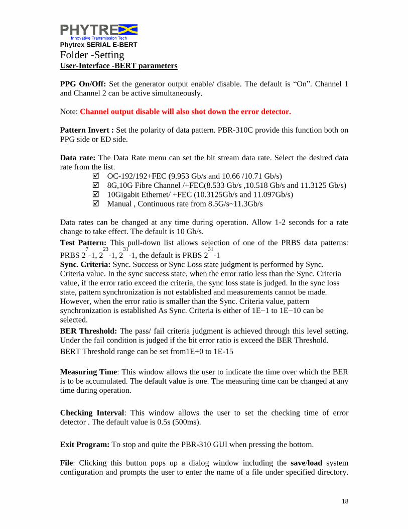
Folder -Setting User-Interface -BERT parameters
PPG On/Off: Set the generator output enable/ disable. The default is “On”. Channel 1
and Channel 2 can be active simultaneously.
Note: Channel output disable will also shot down the error detector.
Pattern Invert : Set the polarity of data pattern. PBR-310C provide this function both on
PPG side or ED side.
Data rate: The Data Rate menu can set the bit stream data rate. Select the desired data
rate from the list.
OC-192/192+FEC (9.953 Gb/s and 10.66 /10.71 Gb/s)
8G,10G Fibre Channel /+FEC(8.533 Gb/s ,10.518 Gb/s and 11.3125 Gb/s)
10Gigabit Ethernet/ +FEC (10.3125Gb/s and 11.097Gb/s)
Manual , Continuous rate from 8.5G/s~11.3Gb/s
Data rates can be changed at any time during operation. Allow 1-2 seconds for a rate
change to take effect. The default is 10 Gb/s.
Test Pattern: This pull-down list allows selection of one of the PRBS data patterns:
PRBS 27
-1, 223
-1, 231
-1, the default is PRBS 231
-1
Sync. Criteria: Sync. Success or Sync Loss state judgment is performed by Sync.
Criteria value. In the sync success state, when the error ratio less than the Sync. Criteria
value, if the error ratio exceed the criteria, the sync loss state is judged. In the sync loss
state, pattern synchronization is not established and measurements cannot be made.
However, when the error ratio is smaller than the Sync. Criteria value, pattern
synchronization is established As Sync. Criteria is either of 1E−1 to 1E−10 can be
selected.
BER Threshold: The pass/ fail criteria judgment is achieved through this level setting.
Under the fail condition is judged if the bit error ratio is exceed the BER Threshold.
BERT Threshold range can be set from1E+0 to 1E-15
Measuring Time: This window allows the user to indicate the time over which the BER
is to be accumulated. The default value is one. The measuring time can be changed at any
time during operation.
Checking Interval: This window allows the user to set the checking time of error
detector . The default value is 0.5s (500ms).
Exit Program: To stop and quite the PBR-310 GUI when pressing the bottom.
File: Clicking this button pops up a dialog window including the save/load system
configuration and prompts the user to enter the name of a file under specified directory.

Phytrex SERIAL E-BERT
19
Use a .txt extension to make the file readable by Microsoft Notepad. Save to database is
completion of each measuring time, error count and error ratio results are appended to
database the file and it was readable through Microsoft Access. If an existing filename is
used, results will be appended to the end of that file. The file has 8 columns, viz., date,
time, gating time (seconds), gating time BER, gating time errors, gating time. Opening
the file while the E-BERT PBR-310 GUI is recording data could stop GUI operation or
corrupt data. To use the file while the GUI is running, copy the file into another name or
directory. If the measuring time is set to its default value of 1, the GUI will not prompt
for a file name or record data.
Figure 11: Bit Error Test Mode (left), Error detect setting criteria (right)
PBR-310 has an intelligent pattern synchronization algorithm and, typically, does not
require the user to use this button. The PBR-310 may display a high error rate for 1 or 2
seconds when this button is clicked.
Measuring Mode: Setting testing mode into “Single” or “Repeat”
The measurement modes are defined below.
(1) REPEAT mode
Unit measurement is repeated continuously during the set gating time(measuring time).
(2) SINGLE mode
Unit measurement is performed once during the set gating time.
Start/Stop: When pressing the “Start”, it clears the previous testing result and begin the
new testing event with respective gating time, error count, and BER, until pressing the
“Stop”

Phytrex SERIAL E-BERT
20
Folder -BER
Measurement Result
Figure 12: Bit Error information for Channel 1 and Channel 2
Time: Indicates the time that has elapsed within the current gating interval.
Error Count: Indicates the number of bit errors in the previously elapsed second. This
display is refreshed every half second.
Bit Error Rate: Displays the BER (graphical) up to the last elapsed second within the
current gating interval. The graphical display plots the gating time BER versus time in
half second unit. The scrollbar allows viewing the BER over 24 hours. Drag and hold the
scroll button along the scroll bar at the desired location. Once the scroll button is released,
the graph scrolls forward automatically to display the latest BER result.
Status: Indicate the pattern checker status, there are several status for pattern
checker.(Table3)
Status Lamp
1 Not Synchronized. SYNC LOSS 2 Checking pattern. No error yet. Check
3 Checking pattern. Error detected. Error
4 Finish checking. No bit error. Pass
5 Finish checking. Error detected. Fail
6 Error counter full. SYNC. LOSS, Fail, ERROR
Table 3: Pattern Checker Status and Lamp display

Phytrex SERIAL E-BERT
21
Lamp Indicator SYNC. Loss: Indicates the synchronization was fail, please check the pattern type and
polarity on Error Detector if it is same as Generator, or adjust the sync. criteria threshold
to more looser level
Error : The lamp will light on when error occur during the measuring period
PASS : No error occur or the bit error ratio(BER) is below the threshold during the
measuring period.
Fail: Error bit occur or bit error ratio(BER) is over the threshold during the measuring
period.
Status : The lamp will display in different color for different status under the measuring
process.
Note:
Error Ratio: ( Number of Error bit under the specified measuring time) / (Number of
total bits over the measuring period)
Error Count: Number of error bits under the specified measuring period.

Phytrex SERIAL E-BERT
22
Folder -History This folder indicates the BER history expressed as table or histogram type. Fig. 10 shows
the BER and relative information versus time, hereafter we will make the brief
introduction.
Figure 13. Error/BER information
Table Item Description
Data Time Indicate the no. of checking interval over the measuring
period
Error Count Accumulation no. of error from start test to current state
Bit Error Rate Accumulation BER from start test to current state
Actual Time Indicate the corresponding date and time on your PC.
Table 4: BER Information history

Phytrex SERIAL E-BERT
23
Observe the Eye Diagram (EyeTrex)
Here are some quick tips to guide the user quickly access the EyeTrex mode to observe
the Eye Diagram of DUT.
Figure 14. Operation sequence to observe the eye diagram
1. Switch to the EyeTrex Mode from left side menu
2. Switch to Eye diagram test screen
3. Setting the measuring items (eye diagram parameters)
4. Setting single/repeat mode for waveform acquisition, the measuring result will be
clear and reset when it start an new acquisition
5. Start the waveform acquisition
Setting Items Here is the setting items under the EyeTrex mode
I. Eye Diagram measurement parameters
- Amplitude
- P-P Jitter
- RMS Jitter
- Rising Time (20%~80%)
- Falling Time (20%~80%)
- Data Rate
- Eye SNR
II. Eye Mask Test

Phytrex SERIAL E-BERT
24
Standard Mask Selection
Ethernet
- 10GbE-WAN(o) 9.953Gb/s
- 10GbE-WAN(e) 9.953Gb/s
- 10GbE-LAN (o)10.3125Gb/s
- 10GbE-LAN (e)10.3125Gb/s
SONET/SDH
- STM64/OC-192 9.953Gb/s
- FEC1066 10.664Gb/s
- FEC1071 10.709Gb/s
Infiniband/Fiber Channel
- 8GFC 8.5Gb/s
- 10GFC 10.3125Gb/s
- 10GFC+FEC 11.096
III. Mask Margin (Positive)
0~100% (0=default)
IV. Histogram (Vertical/ Horizontal Axis)
- ON/OFF
V. Contour
- ON/OFF
Waveform Parameter , Mask Test and Contour Measurement Setup
Figure 15: Eye Diagram Parameters Setup Screen

Phytrex SERIAL E-BERT
25
Figure 16: Eye Diagram Display and Test Result
Perform the Self-Test - Cable Connection
(1) Channel 1 PPG Data/ Output Scope Data/ Input
(2) Channel 2 PPG Data/ Output Scope Data/ Input
(Please add 50Ohm load with non-use port when perform with single end connection)
- GUI Operation
(1) Setting Data Rate and Pattern Type , enable the Channel 1 / Channel 2 PPG
(2) Select EyeTrex Mode and EyeTrex Folder to perform the Eye Diagram Test
(3) Press "Setup" button , select the Eye Diagram testing parameters and enable the
mask test
(4) Press "Single/Repeat" button to switch the testing mode
(5) Press "Get Eye" button to acquire the Eye diagram

Phytrex SERIAL E-BERT
26
Figure 17 , 8.533Gb/s PRBS31,30%Mask Margin
Figure 18, 9.953Gb/s PRBS31 ,30% Mask Margin
Figure 19, 10.3125Gb/s PRBS31, 30% Mask Margin

Phytrex SERIAL E-BERT
27
Figure 20, 10.518Gb/s PRBS31, 30% Mask Margin
Figure 21, 10.709Gb/s PRBS31, 30% Mask Margin
Figure 22. 11.1Gb/s PRBS31, 30% Mask Margin
Phytrex SERIAL E-BERT
28
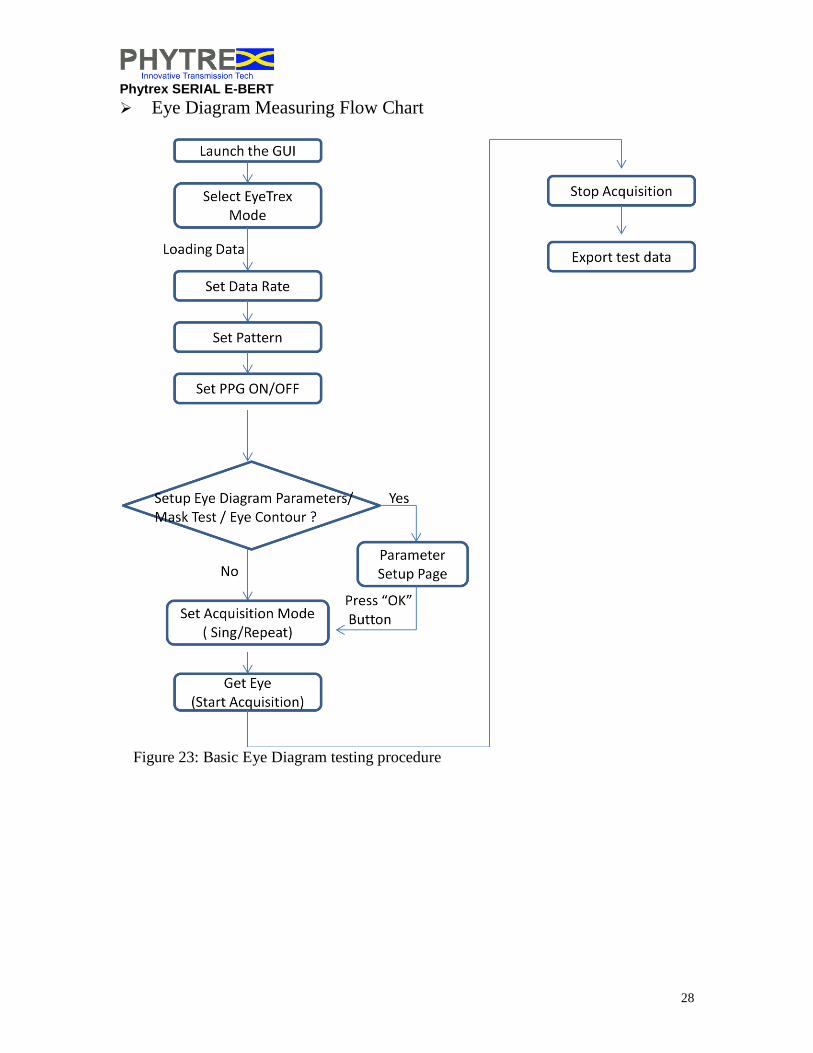
Eye Diagram Measuring Flow Chart
Figure 23: Basic Eye Diagram testing procedure

Phytrex SERIAL E-BERT
29
Clock Recovery (option 08)
PBR-310 embedded the clock recovery circuit, the recovery clock can be output
from the rear panel. (Figure 24. Rec. Clock) Note: The recovery clock is 1/64 of input data rate
Figure 24, Clock Recovery Output (1/64)
Procedure :
(1) Press the Setting Folder
(2) Press The recover clock pull-down menu
(3) Select the recovery channel (Channel 1 or Channel 2)
Figure 25, Clock Recovery Setup Screen

Phytrex SERIAL E-BERT
30
Figure 26, Recovery Clock Output Waveform @ 8.5Gb/s
Figure 27, Recovery Clock Output Waveform @10.3Gb/s
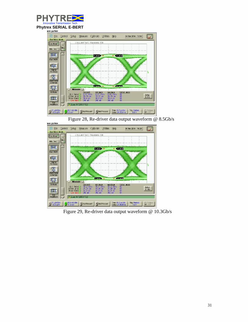
Re-drive Data Output (option 07)
PBR-310C provides re-drive data out from data input on error detector side (Figure
24). This function can support the data output range from 8.5 ~11.1Gb/s with 3 tap
equalizer to pre-compensate the channel loss on the media, (e.g. PCB or Fiber
cable...etc)
Phytrex SERIAL E-BERT
31
Figure 28, Re-driver data output waveform @ 8.5Gb/s
Figure 29, Re-driver data output waveform @ 10.3Gb/s
Phytrex SERIAL E-BERT
32
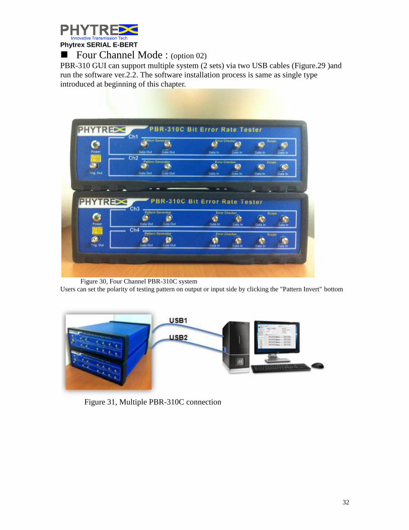
Four Channel Mode : (option 02) PBR-310 GUI can support multiple system (2 sets) via two USB cables (Figure.29 )and
run the software ver.2.2. The software installation process is same as single type
introduced at beginning of this chapter.
Figure 30, Four Channel PBR-310C system
Users can set the polarity of testing pattern on output or input side by clicking the "Pattern Invert" bottom
Figure 31, Multiple PBR-310C connection

Phytrex SERIAL E-BERT
33
Figure 32, Four Channel Mode ID insert screen shot
Figure 33, Four Channel Mode Operation GUI

Phytrex SERIAL E-BERT
34
Figure 34, Four Eye Diagram Measurement and Result Display

Phytrex SERIAL E-BERT
35
Chapter 4 – Labview Driver Programming Guide
Introduction This chapter describes the functionality of the PBR-310 Labview Driver. The main intention of the software is provided to support for the control of the E-BER to make the test and measurement programs.
Figure 35: Remote access and custom application development with PBR-310C VISA
Driver for Labview
Installation Installation the Labview diver must be under NI Labview 7.0 environment.
Step 1.Select E-BERT Labview Diver.exe to start installation
Step 2.Installation result in under the following folder Function panel >>All
Functions>>User Libraries>>E-BER (Figure 19)
Phytrex SERIAL E-BERT
36
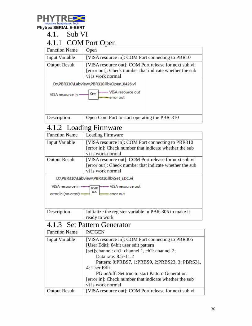
4.1. Sub VI
4.1.1 COM Port Open Function Name Open
Input Variable [VISA resource in]: COM Port connecting to PBR10
Output Result [VISA resource out]: COM Port release for next sub vi
[error out]: Check number that indicate whether the sub
vi is work normal
Description Open Com Port to start operating the PBR-310
4.1.2 Loading Firmware Function Name Loading Firmware
Input Variable [VISA resource in]: COM Port connecting to PBR310
[error in]: Check number that indicate whether the sub
vi is work normal
Output Result [VISA resource out]: COM Port release for next sub vi
[error out]: Check number that indicate whether the sub
vi is work normal
Description Initialize the register variable in PBR-305 to make it
ready to work
4.1.3 Set Pattern Generator Function Name PATGEN
Input Variable [VISA resource in]: COM Port connecting to PBR305
[User Edit]: 64bit user edit pattern
[set]:channel: ch1: channel 1, ch2: channel 2;
Data rate: 8.5~11.2
Pattern: 0:PRBS7, 1:PRBS9, 2:PRBS23, 3: PBRS31,
4: User Edit
PG on/off: Set true to start Pattern Generation
[error in]: Check number that indicate whether the sub
vi is work normal
Output Result [VISA resource out]: COM Port release for next sub vi

Phytrex SERIAL E-BERT
37
[error out]: Check number that indicate whether the sub
vi is work normal
Description Configuration for Pattern Generation
4.1.4 Set Pattern Checker Function Name PATCHK
Input Variable [VISA resource in]: COM Port connecting to PBR310
[set]:ch1: channel 1, ch2: channel 2
Pattern: 0:PRBS7, 1:PRBS9, 2:PRBS23, 3:
PBRS31, 4: User Edit
Timer: The period of Error Detect(time unit: sec)
ED on/off: set true to start Error Detect
[But _EDPatternInvert]: set true to invert the electrical
signal that ED receive
[error in]: Check number that indicate whether the sub
vi is work normal
Output Result [VISA resource out]: COM Port release for next sub vi
[error out]: Check number that indicate whether the sub
vi is work normal
Description Start or Stop error detecting. Set the pattern for pattern
checker
4.1.5 Get Pattern Check Result Function Name Get_Patchk
Input Variable [VISA resource in]: COM Port connecting to PBR305
[channel]:ch1: channel 1, ch2: channel 2
[set]:Datarate: 8.5~11.2(Gbps)
Timer: The period of Error Detect(time unit: sec)

Phytrex SERIAL E-BERT
38
[error in]: Check number that indicate whether the sub
vi is work normal
Output Result [VISA resource out]: COM Port release for next sub vi
[Result]: Total Bits: Detector check bit count
Error Count: error count Detector has detected
Timer: the time last to finish test
BER: Bit Error Rate
Status:
Not Synchronized.
Checking pattern. No error yet.
Checking pattern. Error detected.
Finish checking. No bit error.
Finish checking. Error detected.
Error counter full.
[error out]: Check number that indicate whether the sub
vi is work normal
Description Get Pattern Check Result

Phytrex SERIAL E-BERT
39
Sample code:

Phytrex SERIAL E-BERT
40
Compliance and Certification
FCC Part 15 Compliance This product has been tested and found to comply with the limits for a Class A digital
device, pursuant to Part 15 of the FCC Rules. These limits are designed to provide
reasonable protection against harmful interference when the equipment is operated in a
commercial environment. This equipment generates, uses, and can radiate radio
frequency energy and, if not installed and used in accordance with the instruction manual,
may cause harmful interference to radio communications. Operation of this equipment in
a residential area is likely to cause harmful interference in which case the user will be
required to correct the interference at the user’s own expense.
UL/IEC Safety This product is UL and cUL Listed to the requirements of Standard UL/IEC 61010-1
Second Edition, “Safety requirements for electrical equipment for measurement, control,
and laboratory use - Part 1: General requirements”.
FDA/IEC Laser Safety The E-BERT is classified by the manufacturer as a Class 1 Laser product under the
requirements set by FDA/CDRH 21 CFR 1040.10 and IEC 60825-2.
CE Mark This product has been tested for compliance with the applicable Harmonized Standards
under the European Commission EMC Directive 89/336/EEC and the Low Voltage
Directive 73/23/EEC including amendments to both Directives.
Modification of a certified product. The modification of a laser product, previously certified under Sec. 1010.2, by any
person engaged in the business of manufacturing, assembling, or modifying laser
products shall be construed as manufacturing under the act if the modification affects any
aspect of the product's performance or intended function(s) for which this section and Sec.
1040.11 have an applicable requirement. The manufacturer who performs such
modification shall re-certify and re-identify the product in accordance with the provisions
of Title 21 Sections 1010.2. and 1010.3.

Phytrex SERIAL E-BERT
41
Software License Agreement
Phytrex Corp. (“Phytrex”) agrees to license to you (“Licensee”) Phytrex’s Software provided with the PBR-310 upon the terms and
conditions of this license.
1. DEFINITIONS.
(a) “GUI” means Phytrex’s E-BERT GUI.
(b)“Software” means GUI and any and all other software and firmware provided with Phytrex’s hardware, copies of such software
provided electronically, or on disks or other media, user documentation, packaging and any enhancements, modifications, updates,
bug fixes, releases, patents, patent rights, copyrights, trade secrets, know-how and other intellectual property related thereto.
(c) “Derivative Works” means any revision, modification, product specific application, abridgement, condensation, expansion,
collection, agglomeration or other form in which the Software may be recast, transformed, or adapted.
(d) “Designated System” means any computer hardware or operating system designated on Purchase Order’s resulting from the MOU.
2. GRANT OF LICENSE. Phytrex hereby grants to Licensee a perpetual, non-sub-licensable, non-exclusive license (the “License”) to
internally use, reproduce and create Derivative Works of the Software or portions thereof for internal business purposes only and not
on behalf of any third party. Phytrex reserves the right to exploit the Software and/or any Derivative Works commercially or to license
others to make, use, or sell the same for any purpose, commercial or otherwise. Licensee shall not: (a) remove any product
identification, copyright notices, or other notices or proprietary restrictions from the Software; (b) transfer, sell, assign, sublicense or
otherwise convey the Software to another party; or (b) cause or permit reverse engineering, disassembly, or decompilation of the
Software. With respect to GUI, this License is limited to use solely on the Designated Systems.
3. OWNERSHIP. PHYTREX RETAINS ALL RIGHTS NOT EXPRESSLY GRANTED TO LICENSEE IN THIS LICENSE. The
Software is the confidential and proprietary product of Phytrex and is protected by copyright, trade secret, and other intellectual
property law. Phytrex shall at all times retain all right, title, and interest, including all intellectual property rights, in the Software.
Licensee is granted only the right to use the Software and does not acquire any rights, express or implied, in the Software, other than
those specified in this License. Licensee shall not disclose and shall exercise all reasonable precautions to prevent access to or
disclosure of the Software, except to persons whose access to it is necessary for the effective and efficient use of the Software and
Phytrex’s hardware by Licensee. Licensee shall be responsible for all damages caused by unauthorized disclosure or copying by
persons having access to the Software in the possession of Licensee. Subject to the rights of Phytrex in and to the Software, and
Derivative Works created by the Licensee, Licensee will have sole and exclusive title to the Derivative Works created within the scope of the license granted herein.
Notwithstanding the assignment of ownership, Phytrex reserves the right to use and create the same or similar Derivative Works
without infringing on the ownership rights of the Licensee.
4. WARRANTY. THE SOFTWARE IS LICENSED TO LICENSEE “AS IS” AND IS FREE OF ANY EXPRESS OF IMPLIED
WARRANTY THAT THE SOFTWARE WILL OPERATE CONTINUOUSLY OR BE ERROR FREE. TO THE FULL EXTENT
ALLOWED BY LAW PHYTREX DISCLAIMS ALL WARRANTIES OF MERCHANTABILITY AND FITNESS FOR A
PARTICULAR PURPOSE.
5. INDEMNIFICATION. Licensee shall indemnify Phytrex and its directors, officers, employees and agents and defend and hold each
of them harmless from and against any and all losses, damages, liabilities, costs and expenses(including reasonable attorney’s fees and
expenses) in connection with any and all third party liability, suits investigations, claims or demands (collectively, “Losses”), arising
from or occurring as a result of Licensee’s activities with respect to the Software and Derivative Works. Licensee shall, at its expense,
pay for all costs and attorney’s fees in defending any action brought against Phytrex based on a claim that Licensee’s activities with
respect to the Software and Derivative Works infringes any patents, copyrights, trademarks or other proprietary or intellectual
property right of any third party. Each party shall immediately notify the other party in writing of such a claim. IN NO EVENT WILL
PHYTREX INDEMNIFY LICENSEE OR ANY THIRD PARTY OR BE LIABLE FOR ANY DAMAGES AWARDED TO
LICENSEE OR SUCH THIRD PARTY. Phytrex and Licensee shall cooperate in any legal process concerning alleged infringement of
any third party’s alleged rights arising from Phytrex’s or Licensee’s use of the Software. Phytrex shall have sole control over any
litigation with respect to indemnifiable Losses hereunder and any settlement thereof.
6. LIMITATIONS OF PHYTREX’S OBLIGATIONS. Any modification or attempted modification of the Software by Licensee or
any failure by Licensee to implement improvements and updates to the Software as supplied by Phytrex shall void the obligations of
Phytrex under this License, terminate this License, and entitle Phytrex to seek appropriate legal remedies, unless License has obtained
prior written authorization from Phytrex permitting such modification, attempted modifications or failure to implement.
7. LIMITATIONS ON LIABILITY. UNDER NO CIRCUMSTANCES AND UNDER NO LEGAL THEORY, TORT, CONTRACT,
OR OTHERWISE, SHALL PHYTREX BE LIABLE TO LICENSEE OR ANY OTHER PERSON FOR ANY SPECIAL OR
CONSEQUENTIAL DAMAGES OF ANY CHARACTER INCLUDING, WITHOUT LIMITATION, DAMAGES FOR LOSS OF
GOOD WILL, WORK STOPPAGE, COMPUTER FAILURE OR MALFUNCTION, OR ANY AND ALL OTHER COMMERCIAL
DAMAGES OR LOSSES, EVEN IF PHYTREX SHALL HAVE BEEN INFORMED OF THE POSSIBILITY THEREOF. THIS

Phytrex SERIAL E-BERT
42
ARTICLE STATES THE ENTIRE LIABILITY OF THE PARTIES TO EACH OTHER WITH RESPECT TO INFRINGEMENT OF
ANY THIRD PARTY INTELLECTUAL PROPERTY RIGHTS, AND ANY OTHER THIRD PARTY CLAIMS, OF ANY KIND,
ARISING FROM THE SOFTWARE OR DERIVATIVE WORKS. 8. TERMINATION. If not otherwise specified on the Order Form, this Agreement and each license granted under this Agreement will
continue perpetually unless terminated under this Section 7. THIS LICENSE SHALL AUTOMATICALLY TERMINATE
WITHOUT NOTICE TO LICENSEE if Licensee (a) transfers, sells, assigns sublicenses or otherwise conveys the Software to another
party or (b) causes or permits reverse engineering, disassembly, or decompilation of the Software. Upon termination, however caused,
Licensee shall return all copies of the Software to Phytrex and shall certify in writing that all components of the Software have been
returned, made unreadable, or erased from the memory of Licensee’s computers. Either party may terminate this Agreement in the
event the other party (i) terminates or suspends its business, (ii) becomes subject to any bankruptcy or insolvency proceeding under
federal or state statute, or (iii) becomes insolvent or becomes subject to direct control by a trustee, receiver or similar authority. In
addition, either party hereto or may terminate this Agreement at any time by giving written notice to the other party at least sixty (60)
days prior to the effective date of the termination set forth in the notice. Termination of this Agreement or any license will not limit
either party from pursuing other remedies available to it, including injunctive relief, nor will such termination relieve Licensee’s
obligation to pay all fees that have accrued or are otherwise owed by Licensee under any Order Form. The parties’ rights and
obligations pursuant to Sections 2, 3, 4, 5, 6, 7, 10, 11 and 14, and all other provisions that by their terms or nature are intended to
survive, shall survive any termination of this Agreement.
9. EXPORT. The Software is subject to United States export control laws and may be subject to export or import regulation in other
countries. Licensee agrees to comply with all such regulations and acknowledges it has the responsibility to obtain any licenses as may
be required to export the Software.
10. VERIFICATION. At Phytrex’s written request, Licensee shall furnish Phytrex with a signed certification verifying that the
Software is being used pursuant to the provisions of this Agreement and applicable invoices. Phytrex may audit Licensee’s use of the
Software. Any such audit must be conducted during regular business hours at Licensee’s facilities and shall not unreasonably interfere
with Licensee’s business activities. Audits may be conducted no more than once per quarter
11. GOVERNING LAW; ARBITRATION. This Agreement shall be governed by the laws of the State of California, U.S.A., without
reference to conflict of laws principles or statutory rules of arbitration. All disputes arising out of this Agreement shall be settled by
binding arbitration in Sunnyvale, California under the Commercial Arbitration Rules of the American Arbitration Association by three
arbitrators. Each party shall appoint one arbitrator and together their appointees shall select a third arbitrator who shall have
recognized expertise in communications technology. Notwithstanding the foregoing, the parties may apply to any court of competent
jurisdiction for injunctive relief pending arbitration of substantive claims. Costs of arbitration (excluding attorneys’ fees) shall be
shared equally by the parties. If any provision of this Agreement is be held by a tribunal of competent jurisdiction to be contrary to
law, the remaining provisions of this Agreement shall remain in full force and effect.
12. ASSIGNMENT. Licensee may not assign this Agreement or transfer a Software license to a legal entity separate from Licensee.

Phytrex SERIAL E-BERT
43
Customer Service and Contact Information
Please contact Phytrex Technology Corp. for customer service or sales support using the
following information:
World wide web: www.Phytrex.com
Sales information: [email protected]
Contact Information:
Taiwan
Phytrex Technology Corp.
Taipei
110,3F-2,189,Sec.2 Keelung Rd, XinYi District ,Taipei,Taiwan
Tel: 886-2-27352700
Hsinchu
300,8F-16, 81, Shuli Rd, Hsinchu , Taiwan
Tel: 886-3-5169331
China,
Phytrex Technology (Wuhan) Corp.
Wuhan
Tel: 86-27-87259852; Fax: 86-27-87810356
Email : [email protected]
Room 1701,Nan Fang Di Yuan Mansion,No.568,Wuluo Rd.,Wuhan, P.R.China