piano playing mechanisms · piano playing . mechanisms. being a treatise on the design and...
TRANSCRIPT
PIANO PLAYING MECHANISMS
Being a Treatise on the Design and Construction of the Pneumatic Action of the Player-Piano and of the Reproducing
Piano
BY
WILLIAM BRAID WHITE Associate of the American Society of Mechanical Engineers, Technical
. Editor of the Music Trade Review, New York; Author of "Theory and Practice of Pianoforte Building," "Modem Piano Tuning," "The
Piayer-Pianist," etc.
WITH FIFTY-TWO ORIGINAL ILLUSTRATIONS AND A COMPLETE INDEX
NEW YORK EDWARD LYMAN BILL, Incorporated
383 Madison Avenue

Copyright, 1925, by EDWARD LYMAN BILL, Incorporated
Entered at Stationers' Hall, London, England
TO HIS FRIENDS IN THE PIANO AND PLAYER-PIANO
INDUSTRIES Whose generous assistance has been indispensable to him in gathering materials for this book,
THE AUTHOR GRATEFULLY DEDICATES THE COMPLETED RESULT
PREFACE
The object of this book is comprehended in its title. It represents an attempt to cover in a scientific manner and with sufficient completeness the present position of an art which has represented one of the most interesting and fascinating developments in the mechanical history of the Twentieth Century.
The present work constitutes my third attempt to deal with the subject and is by all means the most complete. The fact is that the art has been developing at a remarkable rate of speed and in directions some of which were hardly foreseen when the last book left my pen. So vast indeed have been the changes since 1914 that when a new edition of my "Player-Piano Up To Date" seemed to be called for, I felt that it would be best to re-write the whole work from beginning to end, making it, with the many changes and additions, not a new edition of an old book but the first edition of a completely new one.
I have to offer my heartfelt thanks to all the many friends within the player industry who have so kindly lent their aid in the gathering of materials without which this book could not have been writ-
iii
iv PREFACE
ten. To name any one individual among so many would be to undertake an invidious task, so I have ventured instead to dedicate this work humbly and gratefully to them all.
On the other hand, I must make specific and grateful mention of my brother, H. Sidney White, 0. E., who, at vast sacrifice of a busy man's time, undertook to make for me the exquisitely neat drawings which ornament this book, and form, perhaps, the greater part of its value, Only one who cared enough for the player-piano in itself and for its own fascination to engage in a seemingly endless and highly ungrateful labor for its sake would have taken upon himself the task of translating into mechanical clarity and precision the crude and hasty sketches from my pen, which have formed almost his sole guide from end to end.
WILLIAM BRAID WHITE.
Chicago, March, 1925.
TABLE OF CONTENTS
PAGE
PREFACB ................................................................. iii
CHAPTER I. First Principles .... 1
CHAPTER II. The Modern Player - Piano Described............................. 38
CHAPTER III. Dimensions and Pressures . 111
CHAPTER IV. Automatic Power and Auto- matic Expression . . . 129
CHAPTER V. The Reproducing Piano . . 147
CHAPTER VI. The Coin - Operated Player - Piano .................................... 206
CHAPTER VII. Repair and Maintenance . 216
List of Illustrations . . . 233
Index......................................... 235
CHAPTER I.
FIRST PRINCIPLES.
The pieces of mechanism which are described in this book are known as "player actions," that term being an adaptation, or corruption, of the more comprehensive name, "piano-playing mechanism," meaning machines which, under the control of a music-sheet or "music-roll," operate the tone-producing elements of the piano and perform all kinds of music thereby. There are many varieties of these machines and their use is now so very general that everyone who undertakes the care of pianos must today be well acquainted with their nature and pe-culiarities, if he is not to find himself constantly in the presence of mechanical and musical difficulties which he is unable to solve.
It is not to be expected that the readers of a book like this should be totally unacquainted with the piano itself. This musical instrument, of course, is the basic reason for the existence of the machines which are described in these pages, and, therefore, I should be justified in expecting from every reader a working knowledge at least of the piano action. For the sake of certainty, however, let me describe
1

2 Piano Playing Mechanisms
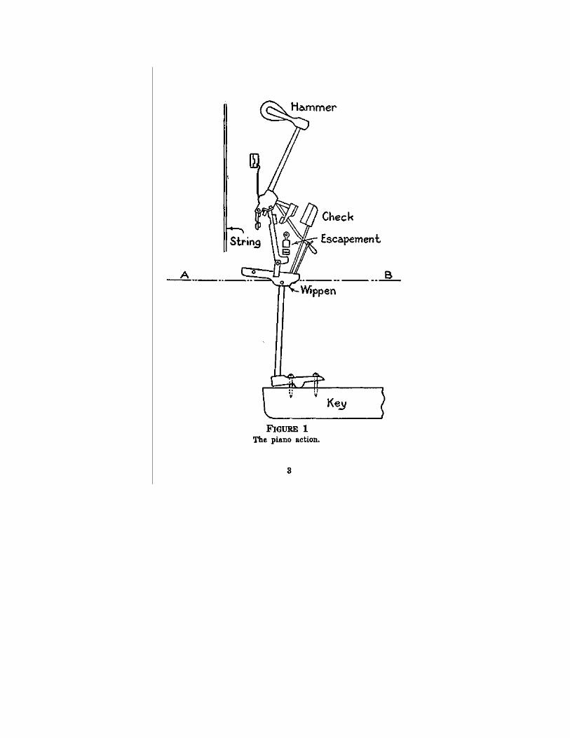
in a few words the mechanics of tone-production of the piano. The description below is illustrated by Figure I.
Mechanism of the Piano.
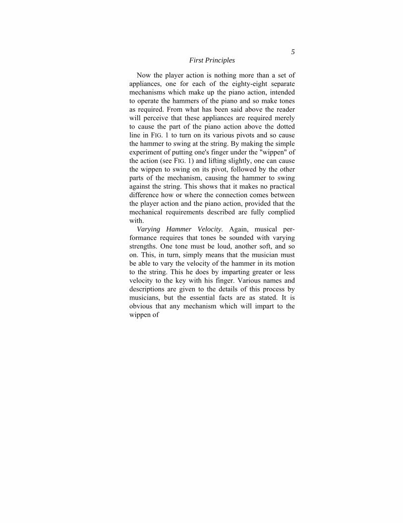
Mechanism of the Piano. A steel string is stretched over a bridge made of wood which, in turn, rests upon a wooden "sound - board," or amplifying table. A "hammer," made of wood covered with felt, is mounted in front of this string and connected by means of what is called a movement or "action," with a "key" which can be depressed, or "struck," as we say, by the finger of the musician. When the key is thus depressed the hammer is moved forward until it is very nearly in contact with the string. Just before contact is established the mechanical connection between the hammer and the key is disengaged by a tripping device called an "escapement," so that the hammer is carried forward to its actual contact by the momentum of the motion first imparted to it when the key was depressed. The hammer thus strikes the string a percussive blow, exactly like the blow of a drum stick upon a drum head. The elasticity of the steel wire is sufficient to cause a reaction which throws the hammer back and away until it is caught by a part of the mechanism known as a "check," and is held there until the key has been released by the finger and is ready for another stroke. The piano, in fact, consists simply of eighty-eight
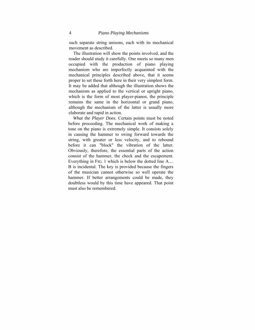
4 Piano Playing Mechanisms
such separate string unisons, each with its mechanical movement as described.
The illustration will show the points involved, and the reader should study it carefully. One meets so many men occupied with the production of piano playing mechanism who are imperfectly acquainted with the mechanical principles described above, that it seems proper to set these forth here in their very simplest form. It may be added that although the illustration shows the mechanism as applied to the vertical or upright piano, which is the form of most player-pianos, the principle remains the same in the horizontal or grand piano, although the mechanism of the latter is usually more elaborate and rapid in action.
What the Player Does. Certain points must be noted before proceeding. The mechanical work of making a tone on the piano is extremely simple. It consists solely in causing the hammer to swing forward towards the string, with greater or less velocity, and to rebound before it can "block" the vibration of the latter. Obviously, therefore, the essential parts of the action consist of the hammer, the check and the escapement. Everything in FIG. 1 which is below the dotted line A.... B is incidental. The key is provided because the fingers of the musician cannot otherwise so well operate the hammer. If better arrangements could be made, they doubtless would by this time have appeared. That point must also be remembered.
5 First Principles
Now the player action is nothing more than a set of appliances, one for each of the eighty-eight separate mechanisms which make up the piano action, intended to operate the hammers of the piano and so make tones as required. From what has been said above the reader will perceive that these appliances are required merely to cause the part of the piano action above the dotted line in FIG. 1 to turn on its various pivots and so cause the hammer to swing at the string. By making the simple experiment of putting one's finger under the "wippen" of the action (see FIG. 1) and lifting slightly, one can cause the wippen to swing on its pivot, followed by the other parts of the mechanism, causing the hammer to swing against the string. This shows that it makes no practical difference how or where the connection comes between the player action and the piano action, provided that the mechanical requirements described are fully complied with.
Varying Hammer Velocity. Again, musical per-formance requires that tones be sounded with varying strengths. One tone must be loud, another soft, and so on. This, in turn, simply means that the musician must be able to vary the velocity of the hammer in its motion to the string. This he does by imparting greater or less velocity to the key with his finger. Various names and descriptions are given to the details of this process by musicians, but the essential facts are as stated. It is obvious that any mechanism which will impart to the wippen of
6 Piano Playing Mechanisms
the piano action (see FIG. 1 again) a turning movement of which the velocity can be controlled, will enable the person who directly or indirectly controls that mechanism to simulate the tone variations produced on the keyboard of the piano by the musician.
The musician varies his key velocity by his muscular action. The player action uses the pressure of atmospheric air. Let us briefly consider how this pressure may be utilized.
The Sea of Air. We all know quite well that we live in a sort of sea of air, which surrounds us, penetrates within our bodies, is breathed in and out by us and extends to a great distance above our heads. Careful measurements disclose the fact that this atmosphere extends to the height of some twenty-five miles above sea level, although the air in the upper regions is so rarified (that is, thin) that human beings cannot breathe it. We all know that it is hard to breathe at the top of a high mountain until we have become accustomed to the thinness of the air there. It is well known, for instance, that visitors to the Rocky Mountains often suffer some distress upon their arrival.
These simple facts lead us to recognize that the air is evidently compressible. If we ask a chemist he will tell us that the atmosphere which we breathe and in which we live is a great sea of very fine and thin gaseous matter, composed mainly of the gases oxygen, hydrogen and nitrogen. Now, it is a pecu-
First Principles 7
liarity of gaseous matter that it always fills completely any closed receptacle into which it is put. If a given quantity of air fills a certain box, and more is then continually added to it, the gaseous particles will be squeezed together and the air will become denser and denser, which is another way of saying heavier and heavier. On the other hand, if some of the original quantity of air is withdrawn from the box, and none allowed to leak in otherwise, the remaining air will expand so as completely to fill the box; but it will be thinner or, we may say, lighter. Since our atmosphere is a great sea of air many miles high, it is plain that the particles at the bottom of this sea (that is to say, on the surface of the earth), must be more closely squeezed together by the pressure of all that is above them than are the particles, say, five miles higher up.
Utilizing the Weight of Air. It has been found long ago that a column of air one inch square in section and as high as the atmosphere, exerts a pressure on the surface of the earth equal almost exactly to 14.75 pounds. We usually express this fact by saying that atmospheric pressure equals 14.75 pounds per square inch. We are usually quite unconscious of this pressure, because it is all around us, pressing equally in all directions, even inside our bodies. Normally, the pressure is equal in all directions and is completely balanced everywhere, so that it is not noticed. Under these ordinary conditions this pressure is unavailable. We cannot
First Principles 9
make any use of it to do any kind of work so long as the object on which the work is to be done is subject to balanced pressure inside and out.
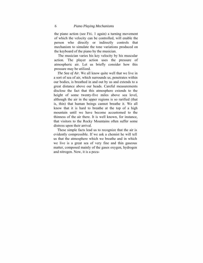
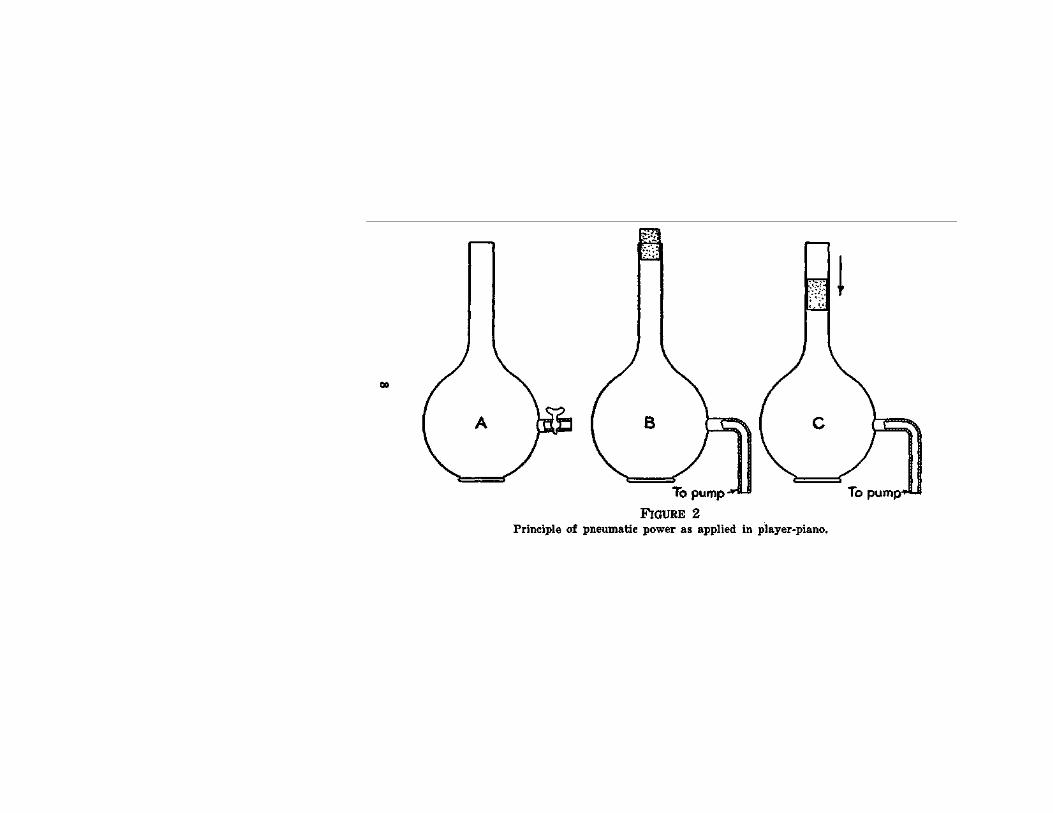
For instance: Here is a flask (FIG. 2-A) with one stop-cock and one opening in it. Suppose we leave the stop-cock open. We know that the flask will be filled with air. The pressure of this air against its sides from the outside will be just the same as the pressure of the air from the inside, and there will be no available energy. But now suppose that we close the opening with a loose-fitting plug (FIG. 2-B) and attach to the stop-cock a tube leading to some sort of air pump. Let the air pump be started up. Air begins to flow at once from the inside of the flask to the pump. But this means that the air remaining must be stretching itself continually in the effort to fill completely the interior of the flask. Therefore, the air inside the flask is constantly becoming thinner, and so exerting less and less pressure upon its sides. But that, in turn, simply means that the equality of inside and outside pressure has been destroyed and that now the outside pressure is pushing against the sides of the flask with a force equal to the difference, whatever it may be, of the two pressures. If, for instance, one-half the amount of air which was in the flask when the openings were closed has been extracted by the pump, the outside pressure will then be equal to 14.75— (14.75-J-2), which is 7.375 pounds per square inch. What will happen is illustrated in FIG. 2-C. The plug will be
First Principles 11
pushed down into the opening by this pressure until it has gone far enough down to compress the inside air back to atmospheric pressure; thereupon, the balance will be restored and the plug will stay at the place to which it has traveled.
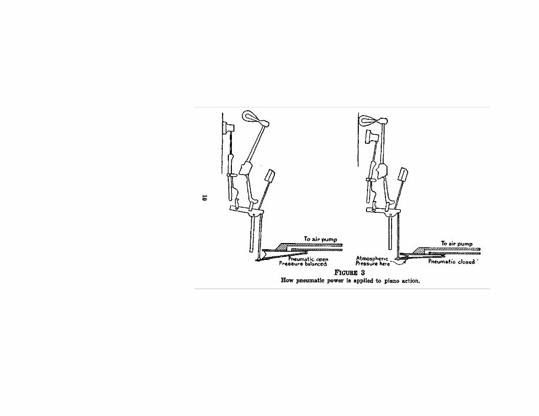
Power Through Partial Vacuum. That simple principle is the principle of the pneumatic player action. A state of reduced pressure or, as it is called, "partial vacuum," is induced in a small bellows called a "pneumatic," one of which is attached in some operative manner to each section of the action of a piano. When some of the air has been pumped out of such a pneumatic the outside pressure pushes up its moving wall, and the motion of this wrall constitutes the movement required to set in motion the corresponding action and hammer on the piano. The next illustration makes this clear (FIG. 3).
The reader will not fail to observe that the velocity of motion of the pneumatic in thus collapsing will depend upon the difference between the exterior, or atmospheric pressure, and the reduced pressure inside the pneumatic. The greater the difference between the two the more effective will be the work of the atmosphere and the higher the velocity of the pneumatic's motion. Thus it appears that the power exerted on the piano hammer (corresponding to the work of the fingers on the keys) by the pneumatic varies as the rapidity of reduction of air-pressure inside it.
12 Piano Playing Mechanisms
It is therefore plain that if we can keep this process of pressure-reduction under control we can vary our tone-strengths as required. Control of this sort is, of course, essential to the artistic rendering of music.
The Working Pressure. Let us see how this reduction of pressure can be undertaken in a practical way. Air pumps are very commonly used for the purpose of obtaining very low pressures, by exhausting the air contained in vessels to a very high degree of thinness. In practice it is found that a highly rarified condition (what is rather inaccurately called a high "vacuum") can be obtained either very quickly by means of extremely high power, or very slowly with very low power. But the purposes of piano playing are served by very moderate powers. In all ordinary circumstances the needed power does not exceed that which is exerted on the moving parts of the pneumatic by a pressure of eight ounces to the square inch of surface. This is equivalent to less than 4 per cent, vacuum, which means that only about one-thirtieth of the contained air need be withdrawn from the pneumatic in order to give enough working pressure to operate the piano action and produce a tone of middle strength. As a matter of fact, an audible sound can be produced with a pressure of only half this. The construction of the kind of air pump used in the player action usually permits, as a maximum, and then only for short periods, the attainment of a working pressure
First Principles 13
not above two pounds per square inch. Nor is anything so high as this needed in any ordinary circumstances.
On the other hand, the quantity of air to be moved is relatively great and, of course, varies very much, according to the number of sections of the piano action (FIG. 1) which are being moved at any one time. The air pump used in the player action is designed (save in certain cases to be explained later) to be operated by the feet of the player-pianist, and, consequently, apart from all other considerations, the task of operating it must not be physically exhausting. All these facts combine to make the power-plant of the player action a slow-moving, low-pressure type of apparatus.
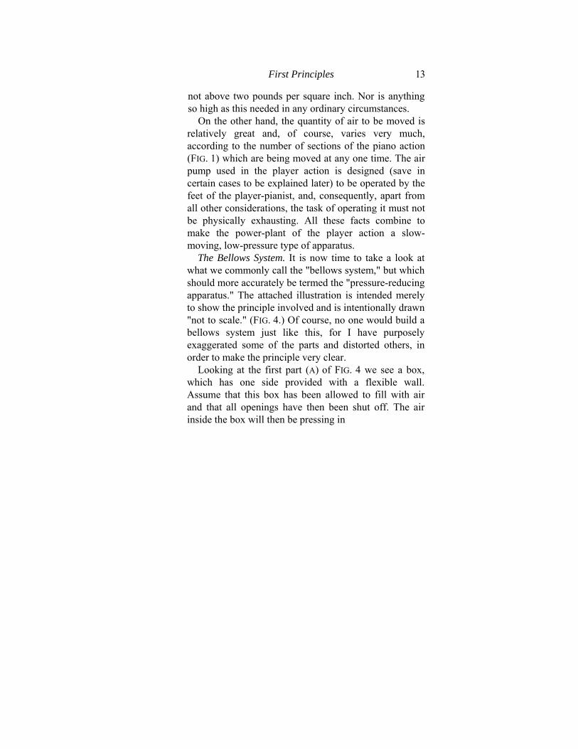
The Bellows System. It is now time to take a look at what we commonly call the "bellows system," but which should more accurately be termed the "pressure-reducing apparatus." The attached illustration is intended merely to show the principle involved and is intentionally drawn "not to scale." (FIG. 4.) Of course, no one would build a bellows system just like this, for I have purposely exaggerated some of the parts and distorted others, in order to make the principle very clear.
Looking at the first part (A) of FIG. 4 we see a box, which has one side provided with a flexible wall. Assume that this box has been allowed to fill with air and that all openings have then been shut off. The air inside the box will then be pressing in

First Principles 15
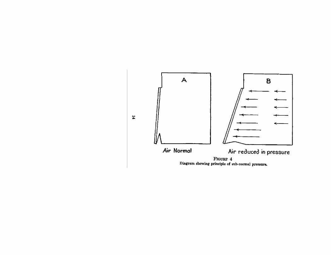
all directions at its normal atmospheric pressure of 14.75 pounds per square inch, a pressure which will operate both inside and outside the box, balanced and equalized and, therefore, unfelt. Now suppose that by some agency the flexible wall is pulled outward (B) . What happens? The air inside the box at once stretches itself in all directions to fill this new space. But no more air can come in from the outside, and so the mass of air already inside must thin out and become, as we say, "lighter." It will thus exert a lesser pressure on any square inch of space inside the box. But since the air on the outside re-mains at its normal pressure of 14.75 pounds per square inch, there is now a difference between the outside and the inside pressures. We have, in fact, created a lower pressure in the box, and so long as the box remains tight with its flexible wall drawn out this lower pressure inside will persist. Now let us turn to FIG. 5 (A). Here we have the same box, but with an opening provided in it leading through a tube into a smaller box, also provided with a flexible wall.
The air in this small, flexible-walled box was cer-tainly at normal atmospheric pressure (14.75 pounds per square inch) before the movable wall of the box was drawn out. But when this latter operation takes place (FIG. 5-B) the air in the smaller box is affected just like the air in the larger box. All the air in the two boxes together is in physical contact, and so when the internal space of the larger
First Principles 17
box is enlarged the resulting thinning out of the air affects all parts of the structure alike. Hence the air in the small box is also slightly thinned out, so that there now exists a difference between the pressure in it and the pressure of the outer air pressing against it. This latter pressure is unavailable so long as it is balanced by the inside pressure. But when the latter, as shown, is artificially lowered, the outer pressure is rendered available. The resulting working pressure, equal to the difference between the inside and outside pressures on the little box, operates against the moving wall of the latter and presses it upward, unless there is some artificial obstacle placed to prevent this. There is none in this case, and so the small box collapses.
The large box is a rudimentary form of the bellows system. The small box is a rudimentary form of the pneumatic. The two, together, comprise a rudimentary form of the player action. The principle here so simply set forth is the principle of every form of pneumatic player action.
The Principle in Practice. Let us now go on to consider how this principle may be applied to the practical work of playing the piano. A musical com-position consists of tones and groups of tones arranged in some pre-determined order, and the operation of playing the piano consists in reproducing a body of such tones in some such order. This introduces the idea of succession in time, as well as the idea of simultaneity. Tones succeed each ofcher, and
18 Piano Playing Mechanisms
tones are also sounded simultaneously. Sometimes the two conditions co-exist, and we have groups of simultaneously sounded tones succeeding and following other groups. It is therefore evident that in order to develop the rudimentary idea a moment ago described, into a mechanism able to play the piano, we must introduce these new ideas of controlling the motions of the operating parts of the piano so as to allow for both successive and simultaneous action of any number of them, and this according to any pre-determined order. We therefore need (1) means for lowering and raising the pressure existing at any time in each of the eighty-eight pneumatics, which represent together the entire outfit for playing all the strings of the piano; (2) means for determining in what pneumatics the pressure shall be raised or lowered; and (3) means for governing the simultaneity, succession and time-order of the above processes.
The methods actually adopted are extremely simple, although their present shape represents the culmination of some fifty years of experiment, and many disappointments. The problem of determining order, succession and simultaneity has been solved by the invention and application of the traveling perforated sheet. The translation of the sheet's motions and mechanical actions into control of the pneumatics has been solved by the invention of the pneumatic and valve. A brief consideration will enable us to grasp the process in its entirety.
First Principles 19
By referring again to the ideas set forth in FIG. 4, we can see that if the moving wall of the large box were kept moving forward, i.e., were being stretched out, to an indefinite length, the contained air would become thinner and thinner as the interior space became more and more enlarged. The same condition precisely can be brought about, however, in a more convenient manner. Suppose, for instance, that the moving wall of the box be arranged so that it can be pushed back, in readiness for a second pull forward, without restoring the original condition as to the interior air-pressure. If this can be managed we have only to pull our wall out and push it in as often as we please in order to be able to thin out the contained air to any required extent. A way of doing this is shown in the accompanying illustration, FIG. 6. The arrangement is simple.
The large box (A) and the small triangular box with the moving wall (B) are divided from each other by a barrier (o), in which are bored holes (E-1) . Over these holes is laid a strip of some flexible but air-proof material, fastened at either extremity but stretched loosely enough to permit a slight bellying over the region of the holes (E-1) when a current of air is directed from the opposite sides of the holes. Plainly, when B is pulled outward the air in A will move towards B and will push aside c in its effort to get into B. The pressure of the air in doing this will at the beginning of the operation equal the total pressure of the atmosphere,

First Principles 21
because B at the beginning of the operation is pressed close up against A and so is unable to contain any air until it has been opened.
So far all is simple. Now, suppose we have opened B as far as it will go. In order to continue the process we must find some way of maintaining the conditions we have set up until we can get B back again to its original position, from which we can once more pull it open. Here comes in the strip c again. As soon as we start to push B back to its original position the air inside B pushes against c and seals up the passageway E-1, SO that no air can get in from A. But B is filled with air, which is rapidly compressing as we push it inwards. Here now comes in the strip D. AS soon as we start to close B, D is thrust open by the air in B, which, as B is pushed further inwards, is more and more compressed, thus pushing D open against the pressure of the atmo-sphere and, through the holes E, squeezing out all the air inside B as the two walls thereof come together. By this simple device B is relieved of all air, and by the time we are ready to pull it open again it is once more in its original condition and ready to extract another lot of air from A. Given two of these elements B, operated by a system of levers worked by the feet, we have the bellows system of the player-piano in its simplest form. It can easily be seen that the system I have described is able to move relatively large quantities of air, but is not able to reduce the pressure to the condition of what
First Principles 23
is called, in pneumatic engineering, "high vacuum." As explained above, however, high levels of vacuum are not needed for the purpose of the player-piano.
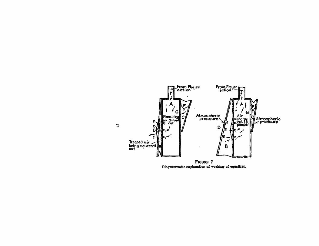
But there is still something to be considered before we can call our bellows system perfect. For it is evident that the arrangement of two alternately expanding and contracting compartments, which we may now call by the rightful names of "exhausters," will not suffice to give us that continuous flow of air from the player-piano action to the atmosphere which is needed to maintain the state of partial vacuum when the player action is playing. Periodically there comes the moment when one exhauster is entirely closed and one entirely open, and when no power is being produced. It is necessary, therefore, to have some arrangement whereby these moments of inaction may be bridged. The ingenuity of reed organ and harmonium builders many years ago was confronted by a similar problem, and a solution was found in the so-called "reservoir." An almost identical method has been adopted for the player-piano bellows, but for reasons which should be obvious it is better to use the term "equalizer" in the latter case.
The Equalizer System. Reference to FIG. 7 will show clearly the principle and method of the equalizer system. The equalizer is simply an automatic exhauster, which is put into action when the balance between the outside and inside pressures is disturbed beyond a certain level. In FIG. 7, the first

24 Piano Playing Mechanisms
diagram shows all the parts at rest. The exhauster B is closed and the equalizer c is held open by the spring F, and remains expanded. In the second diagram the exhauster B has been pulled outward, thinning the air in the chest A, and causing the normal-pressure air in the player action to descend into the thinned-out region in A and B. Meanwhile, just as soon as the air in the equalizer c, which is in communication with A and B by the passage G, feels the disturbance caused by pulling outwards the exhauster B, it also begins to move into A and thus helps to restore the pressure-balance caused by the thinning out of the air when the space B was opened up. The air in c then is also thinned out and, as soon as the resulting difference in pressure between the air inside and the air outside (which never changes its pressure of course) is greater than the expansive power of the spring, the external pressure will push inwards the moving wall of the equalizer 0. Now, just as soon as there comes any in-seepage of air from the player action in sufficient quantity to upset the delicate differences in pressure on which the working of the player-piano depends, the spring of the equalizer will no longer be balanced and will begin again to push outward the moving wall of the equalizer c. The moment that this outward movement begins the equalizer itself becomes an exhauster and helps to thin out the air in the chest A and in the player-action above, continuing to do this until it has fully opened, by which time
First Principles 25
the exhausters will have come into action again with enough power to restore the needed operating pressure.
Of course, the faster the exhausters are worked, other things being equal, the less opportunity will there be for the equalizers to function; but the beauty of this system is that it functions only when it is needed and at other times does no harm even if it does no good. All bellows systems used in player-pianos are constructed according to the principle laid down, although there is much variety in details.
Sub-normal and Super-normal Pressures. Let us pause here a moment to remind ourselves that the operating pressure of which we have been speaking means whatever difference between the inside and the outside pressure may be needed at any moment to make the instrument play the music it is at that moment engaged with. The operating pressure, therefore, is never steady, as the demands made upon the bellows are constantly changing with the demands of the music. The sounding of each tone, as will hereafter be explained, involves the entry of some atmospheric air into the closed spaces of the action, so that there is a constant struggle to maintain the needed partial vacuum or operating pressure. Fortunately, the requirements are always light. This being clear, let the reader remember that a pressure is still a pressure, even if it be below that of the atmosphere. It is not the "partial vacuum" which
First Principles 27
is doing the work, for the term "vacuum," complete or partial, is merely an expression of the fact that there it either no air at all in a space, or else that the pressure of the contained air is lower than that of the atmosphere. "Emptiness" (vacuum) is only an abstract idea, and abstract ideas do not perform physical work. The atmosphere does the work and the only task of the bellows system is to establish and maintain a condition of sub-atmospheric pressure inside itself and the player action, whereby the atmosphere, pushing from the outside on equalizers, valves and pneumatics, may do the work. The lower the inside pressure the higher the outside pressure in proportion, and the larger the quantity of work that can be done.
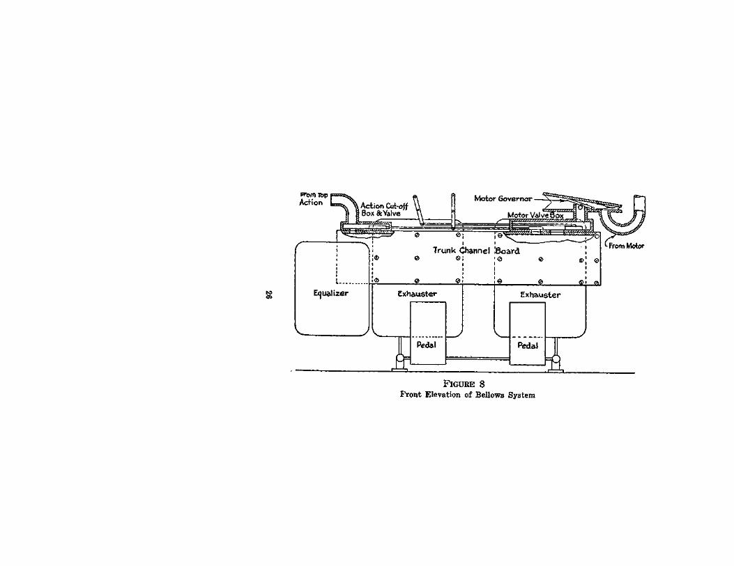
The Bellows System Complete. We are now ready to examine a diagram showing a complete bellows system. This is not a copy of any one in particular, but may be considered typical. All the parts shown in it are common to all player-pianos, although there are many slight differences of dimension, position, number of units of each kind, etc. But what is shown here will give the reader all needed knowledge to enable him to understand any existing bellows system.
In FIGS. 8 and 9, then, we perceive the two ex-hausters, each with its foot-treadle; the equalizers, and the connections from the playing action and from the pneumatic motor which rotates the music-roll,
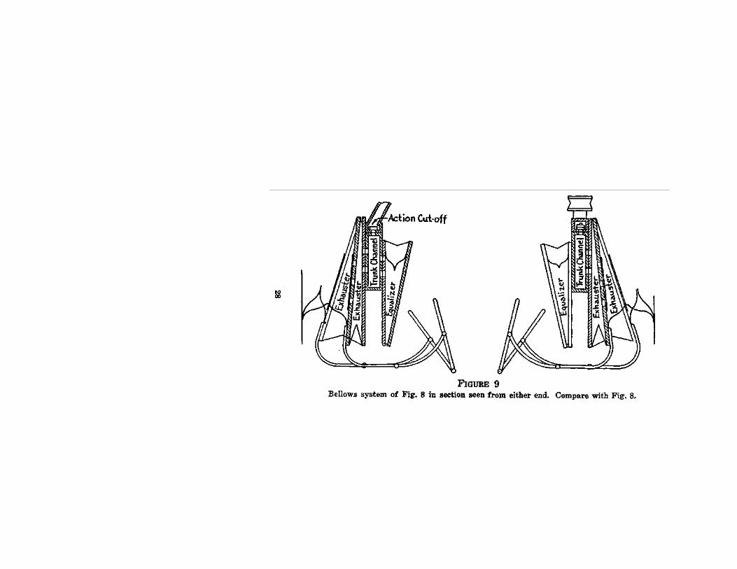
First Principles 29
respectively. The music-roll, the method of using it, and its functions as a continuous traveling controlling valve will be discussed in due course, but for the moment we shall attend only to the action of the bellows upon some such pneumatic system as is described in outline above.
From what has already been said it is clear that if the exhausters are alternately opened and closed by the action of the feet on the treadles, any air which is contained within the bellows-system will be exhausted out into the atmosphere by gradual steps, as already described. If, then, the action cutoff valve between the pneumatic playing mechanism and the bellows (shown in the top left-hand corner of FIG. 8 and in section in Fid. 9) be in the "open" position, the air contained in the playing mechanism will travel downwards into the bellows system, by gravity, as the air below it is gradually exhausted out into the atmosphere. Hence, there will result a reduced pressure in the playing mechanism, which may be controlled in any suitable manner so as to operate the piano action and perform music.
I have already said as much as is necessary con-cerning the physical operations which constitute the performance of music on the piano. From what was then set forth the reader will understand that the method of control of pneumatics now aimed at needs to fullfil two requirements: (1) Any and all pneumatics must be caused to open or close at will; (2) the selection and succession of the openings
30 Piano Playing Mechanisms
and closings must be so controlled as to cause the resulting' musical sounds produced from the piano to correspond with the sounds of some pre-deter-mined pieces of music.
The Valve System. The first of these requirements introduces us to the valve system of the pneumatics. The second brings before us the perforated music-roll.
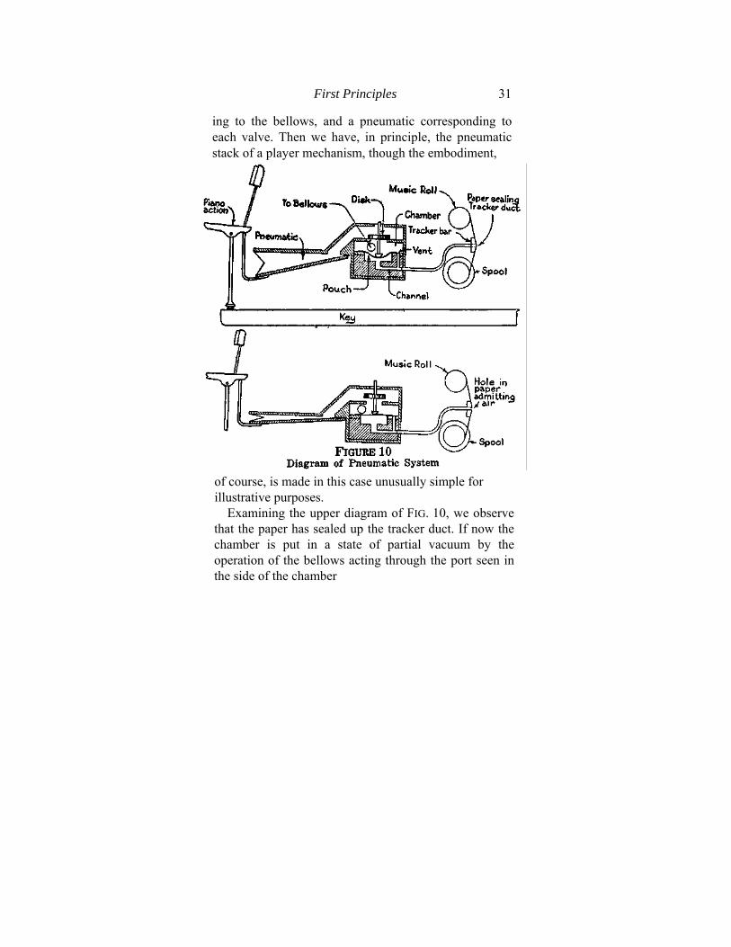
The illustration (FIG. 10) shows in the simplest form a single pneumatic and its controlling valve. The valve consists of a disk placed so that it rests above a leather pouch or diaphragm. The disk is centered on a wooden spindle. A button at the end of the spindle rests just above the pouch. The latter is bedded on the floor of a chamber, which is connected by means of a suitable port with the bellows system so that a state of reduced air pressure or partial vacuum may be maintained within it. Under the pouch is a channel which is not connected with the chamber save by a small vent and which runs outwards to some suitable point where it may be brought into contact with a sheet of paper adapted to press against its extremity, as shall be disclosed in a moment. (See FIG. 10.)
The top of the disk is exposed to the outer air, but it rests upon the roof of the chamber in such a way as to shut off any air from entering the chamber over its top. Imagine eighty-eight of these valves arranged in two rows along a chamber such as has been described, with one general suction port lead-
First Principles 31
ing to the bellows, and a pneumatic corresponding to each valve. Then we have, in principle, the pneumatic stack of a player mechanism, though the embodiment,
of course, is made in this case unusually simple for illustrative purposes.
Examining the upper diagram of FIG. 10, we observe that the paper has sealed up the tracker duct. If now the chamber is put in a state of partial vacuum by the operation of the bellows acting through the port seen in the side of the chamber
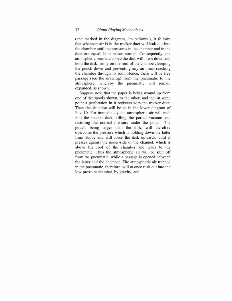
32 Piano Playing Mechanisms
(and marked in the diagram, "to bellows"), it follows that whatever air is in the tracker duct will leak out into the chamber until the pressures in the chamber and in the duct are equal, both below normal. Consequently, the atmospheric pressure above the disk will press down and hold the disk firmly on the roof of the chamber, keeping the pouch down and preventing any air from reaching the chamber through its roof. Hence, there will be free passage (see the drawing) from the pneumatic to the atmosphere, whereby the pneumatic will remain expanded, as shown.
Suppose now that the paper is being wound up from one of the spools shown, to the other, and that at some point a perforation in it registers with the tracker duct. Then the situation will be as in the lower diagram of FIG. 10. For immediately the atmospheric air will rush into the tracker duct, killing the partial vacuum and restoring the normal pressure under the pouch. The pouch, being larger than the disk, will therefore overcome the pressure which is holding down the latter from above and will force the disk upwards, until it presses against the under-side of the channel, which is above the roof of the chamber and leads to the pneumatic. Thus the atmospheric air will be shut off from the pneumatic, while a passage is opened between the latter and the chamber. The atmospheric air trapped in the pneumatic, therefore, will at once rush out into the low-pressure chamber, by gravity, and

First Principles 33
the pneumatic will at once collapse by the action of the atmospheric pressure on its outside moving wall.
Function of the Vent. The reader will of course wonder why the atmospheric air entering the channel did not discharge at once through the vent into the chamber, and so nullify the effect of the opening of the duct. The answer is simple. The vent is too small to empty the channel of atmospheric air so long as an end of the latter is open. The quantity of atmospheric air flowing constantly down into the channel is always greater than the capacity of the vent to reduce its pressure by absorption into the chamber. Therefore, so long as the end of the channel is open—that is to say, so long as a perforation in the paper registers with the end of the channel—it remains under atmospheric pressure, and the pouch and the valve remain up. The pneumatic, in consequence, remains collapsed, operating the piano action, swinging the hammer against the string and producing a sound.
Reverse of the Operation. Now suppose that the hole in the end of the channel is closed, as by the perforation coming to an end and being succeeded by the airtight surface of the paper. Immediately, the atmospheric air trapped in the channel is reduced in pressure by absorption of part of it into the chamber through the vent. Consequently, the pressure under the pouch is reduced below the pressure above the top of the disk. The disk therefore
34 Piano Playing Mechanisms
drops, the roof of the chamber is at once sealed again, and atmospheric air flows into the pneumatic, which re-inflates and causes the release of the piano action, thus terminating the operation.
The Traveling Valve. In order that operations like this should always take place at the right moment, and in respect of the appropriate pneumatics and corresponding sections of the piano action, it is necessary to have some form of over-riding control, as it were, of the whole pneumatic stack. The reader understands that the eighty-eight pneumatics and valves may be assembled in one, two or three rows, and that the chamber may be continu-ous so far as concerns each row. There may be, in fact, forty-four, or twenty-nine, or thirty pouches assembled on the floor of a single long chamber, with a corresponding number of disks working from the pouches, and with one trunk exhaust channel. Usually, pneumatic stacks are assembled in either two or three banks.
But the over-riding control rests on two requirements. The selection of the pneumatics to be operated involves the principle of succession, that is, of time. It also involves pitch or position in the musical scale. The double duty of control is adequately provided by the device of a common terminal for all the channels, controlled by a common traveling valve which, by its motion across the common terminal, provides for the succession of operations in time and for their selection, according to the requirements of pitch.
First Principles 35
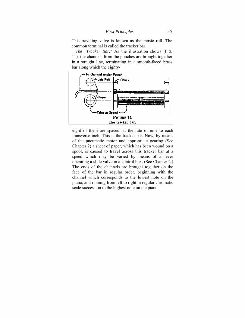
This traveling valve is known as the music roll. The common terminal is called the tracker bar.
The "Tracker Bar." As the illustration shows (FIG. 11), the channels from the pouches are brought together in a straight line, terminating in a smooth-faced brass bar along which the eighty-
eight of them are spaced, at the rate of nine to each transverse inch. This is the tracker bar. Now, by means of the pneumatic motor and appropriate gearing (See Chapter 2) a sheet of paper, which has been wound on a spool, is caused to travel across this tracker bar at a speed which may be varied by means of a lever operating a slide valve in a control box. (See Chapter 2.) The ends of the channels are brought together on the face of the bar in regular order, beginning with the channel which corresponds to the lowest note on the piano, and running from left to right in regular chromatic scale succession to the highest note on the piano,
36 Piano Playing Mechanisms
on the extreme right. The paper sheet is perforated accordingly, and a piece of music is reproduced by punching out on the paper perforations corresponding to the channels which are to be opened. The paper travels at any speed required, under the control mentioned above ("tempo" control), and thus a piece of music may be correctly repeated. The length of each perforation may be determined in relation to all other lengths of perforations on the same sheet, according to any scale of length values adopted. Thus, to give an example, the perforations may be cut so that each one which is to represent a whole note in musical notation shall be four inches long. Then a half-note perforation will be two inches long, a quarter-note perforation one inch long, an eighth-note perforation half an inch long, and so on. Thus, on the music roll the relative position of a perfora-tion from left to right corresponds with pitch, exactly as the relative position of the keys on the keyboard corresponds to the same property. The length of the perforation determines the duration of the sound.*
Actual methods of arranging the perforations on the roll, and the production thereof, may be, and are, various. The roll may be the result of a record automatically drawn off from the actual play of an artist. It may be a mathematical transcription of
♦Theoretically, of course, for the sound of the piano dies away very rapidly. But on the organ, for instance, the statement would be literally true.
First Principles 37
the score. But in all cases the principles laid down above hold good.
We have now discussed the principles of operation of the purely mechanical part of music production through the intermediary of pneumatic playing mechanisms, in the instrument known as a piano.
CHAPTER II.
THE MODERN PLAYER-PIANO DESCRIBED.
In the previous chapter were discussed the general principles of pneumatic piano-playing mechanisms, but only with respect to the consideration of such as are intended to be controlled by the human performer (or player-pianist, to use the now generally accepted term), in order not to complicate the first elementary description. These same principles, however, somewhat differently applied, serve as the foundation of all the most refined and ingenious playing mechanisms of the "automatic-expression," or "reproducing-piano" classes. The reader will find himself able to understand them all in the light of what has been set forth in the previous chapter. But he must first become familiar with the constructional details of the treadle player-piano. After grasping the facts which are now to be set forth, one will have little difficulty in comprehending the descriptions of the more complex automatic-expression mechanisms, which follow.
The treadle player-piano has been from the first the most popular, the least expensive and the best known of all types of pneumatic musical instruments.
38
The Modem Player-Piano Described 39
From every point of view it represents for study subject-matter of the utmost importance, and a complete discussion of its peculiarities is needed at this point. Nevertheless, there is nothing about it which need cause the reader any anxiety regarding his power to understand it, for the discussion which was carried out in the previous chapter will already have set forth the outlines of player-piano construction. It is now chiefly needful to fill in these outlines with necessary detail.
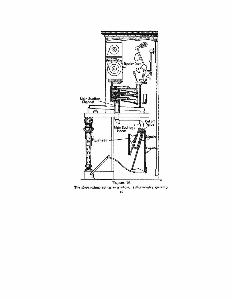
The Player Mechanism as a Whole. In the first place, let us look at a picture of an upright player-piano, as it would appear if seen through its side, and with all parts shown in section. (FIG. 12.)
As the illustration plainly shows, the playing mechanism is assembled in two main divisions. One of these, which is the bellows system or power-plant, is placed under the key-bed of the piano in such a position that the foot treadles may conveniently be operated by the feet of the performer from a sitting posture. Pneumatic connection by means of rubber hose is maintained between this bellows system and the parts of the mechanism which are disposed above the key-bed of the piano. Of these last the most important are (1) the superstructure, and (2) the pneumatic stack.
Referring first to the bellows system, the reader will note that the exhausters and equalizer system are disposed as he will have anticipated from the course of the discussion in Chapter I. The sectional
The Modern Player-Piano Described 41
illustration shows only by implication, the details of the connection between motor and bellows and between bellows and pneumatic stack, but the detail will at once be comprehended by reference to the previous pages. Meanwhile, however, it will be well to consider the various separate parts which enter into the completion of the bellows system, after which we can take up and discuss the details of the pneumatic stack and superstructure.
Bellows Construction. It is usual to build the exhausters and equalizers around a heavy frame of hard wood which, in turn, comprises the covering walls of the trunk channel, whereby communication is maintained between the various working parts (See FIGS. 8 and 9). It is customary to construct the exhausters and equalizers of ply-wood, so as to obtain the highest possible power of resistance to strains or thrusts arising from the use of the treadles or from atmospheric pressure against mov-ing walls. The moving wall of an exhauster may easily have an area of nearly 300 square inches, so that at a playing pressure of twenty-four ounces per square inch (which represents the practical possibilities in fortissimo playing under ordinary circumstances in this class of mechanism) the total atmospheric pressure against the moving wall will be equal to a weight of 450 pounds, which must be moved forward by the foot through a distance of from three to four inches. The virtual absence of friction, of course, reduces very much the strain
42 Piano Playing Mechanisms
upon the foot, but the fact cited will show why it is necessary to build the walls of the exhausters out of ply-wood.
As the reader is aware, it is necessary to attach pressure springs to the moving walls of the exhaust-er so that they may be rapidly closed after they have been thrust forward by the action of the feet on the treadles. These springs are usually made of two steel strips, riveted together at one end and tempered so that they exert considerable resistance to closure and tend to recover their original posi-tions as soon as the closing pressure has been re-leased. These "V" or fan springs, as they are com-monly called, are of various sizes, exerting resist-ances of various weights. It is customary in foot-power player-pianos to provide each exhauster with a spring resistance of twelve to twenty pounds.
The flap valves, which successively open and close during the movement of the exhausters, are com-monly made of strips of well-tanned calf or kid skin about one-thirty-second of an inch or less in thick-ness, fastened to the exhauster board at one end by tacks, and stretched to smooth fitting by a steel wire spring of light resistance. They cover holes drilled through both walls of the exhauster. One is placed outside the moving walls, and the other on the inner side of the fixed wall. (See FIG. 12.)
The flexible sides of the exhausters are made of heavy canvas, impregnated with rubber. During recent years a great deal of attention has been given
The Modern Player-Piano Described 43
to producing special canvas, twills, stockinette and similar materials for use in forming the flexible sides of equalizers, exhausters, governors, playing pneumatics, motors and so on. These materials are now produced in qualities and dimensions deter-mined in the light of much painful experience, and are virtually perfect in airtightness, durability, flexibility and convenience.
Theories of the Equalizer. Turning to the equal-izer one notes at once considerable variety of prac-tice as to number, size and spring resistance. Many hypotheses concerning the proper design and num-ber of the equalizers have been enunciated and worked out, but no final decision has been, or per-haps can be, reached. Now, in order that the reader may understand this last statement, it is necessary for him to remember that the object of the equalizer system is to act as a sort of pneumatic flywheel to the bellows system. The reciprocal, back-and-forth motion of the exhausters, periodically interrupted, requires to be supplemented by some form of auto-matic compensating device. The operation of the equalizer under the influence of the exhausters has already been described (See Page 24). It is now necessary to notice some of the variations in theory and practice which have arisen out of the desire to improve its design and efficiency.
We all know that a flywheel may be attached to a single-cylinder steam engine. After it has been so attached it will, when once set in motion, carry the
44 Piano Playing Mechanisms
crank-shaft at each revolution safely around the dead center. The heavier the flywheel is the smoother will be the resulting motion; but, consequently, at the same time the greater will be the weight to be moved and the smaller the work-delivering capacity of the engine.
Similar reasoning applies in parallel to the equalizer system of the power-plant in the player-piano.
There have always been two schools of thought among designers of player mechanism.. The first has wished to render the mechanism as sensitive as possible to the control of the human performer or player-pianist. Its followers have desired that the player-pianist should "feel" the air under his feet, as it were, and be able to control the working pressure (and in consequence the power of the produced sounds) from moment to moment, so completely as to approach, or even equal, the parallel control exerted by the manual pianist through his fingers on the keyboard. They have wished, in short, to give to the human element the utmost latitude of power and influence in the production of the music of the player-piano.
Those who follow the other school have argued that the player-piano is, after all, likely always to be owned by persons who have no formidable musical knowledge and perhaps little advanced musical feeling. Such persons, it is insisted, need a mechanism as simple as possible, one which calls for no acquired refinement in foot-work, one which plows
The Modern Player-Piano Described 45
along steadily, delivering a steady (though, of course, within limits controllable) volume of sound, and one which, without the exercise of any special intelligence by the player-pianist, delivers music of a grade acceptable to the mass of probable buyers.
It would be probably useless to indicate in these pages the author's preference for one system or the other. The question relates to musical and not to mechanical conditions. The reader, therefore, will be sufficiently served when he has secured an accurate description of the facts. He will meet many instruments embodying all sorts of variants on any type which may be described to him here, and it will be enough for him to realize that the difference is less mechanical than aesthetic.
Connections from Bellows to Upper Actions. In order to understand the forthcoming discussion the reader is asked once more to examine FIGS. 8 and 9. During this examination it will be advisable to note certain other details which may now conveniently be brought to his attention. The drawings show how the connection between the bellows system and the pneumatic stack may be cut off entirely through the simple expedient of moving a slide-valve over the connecting passageway. The process of doing this is always connected, in practice, with the parallel process of opening a large port (See FIG. 8) in the motor valve box, from which is con-trolled the speed of the motor that rewinds the music roll. In other words, when the playing action
46 Piano Playing Mechanisms
is cut off from the bellows all the power of the latter may be thrown on to the motor. Thus, the music roll, at the end of a piece of music, may be rolled up rapidly by throwing a lever (one connection of it shown) which cuts off the action, opens the motor full speed, and at the same time (not shown in the illustration) shifts the gears of the motor so that the roll is wound backwards instead of forwards.
Some such method of "re-rolling" is used on all foot-power player-pianos. The reader will also note in passing that the same drawings (FIGS. 8 and 9) show the bellows system to be connected with the motor valve box and with the motor, including the motor governor. All these details receive full consideration in their proper place, and attention is now directed to them only in passing.
Equalizer Systems Compared. All bellows systems include in some form or other the details just noticed. The illustrations, however, show a sensitive type of bellows system, having only one equalizer, smaller than either exhauster and fitted with a light spring of perhaps twenty pounds pressure. On the other hand, a bellows system of the high-reserve type employs two equalizers, sometimes three, of graduated sizes. One of these will be large and lightly spring - weighted. The other will be smaller and more heavily weighted. The object of the second one is to assure that under any possible conditions of pumping there will never be a moment when the equalizer system is entirely closed. By
The Modern Player-Piano Described 47
the expedient of providing one additional equalizer, or even two, more heavily weighted, the designer may be sure that even if the player-pianist habitual-ly pumps too vigorously he will never find it im-possible to get still another heavier sound-crash above the last. The mechanical explanation of this fact is worth a short description.
The function of the equalizer, as already seen, is to act as a sort of flywheel. The heavier a flywheel is, the better it steadies the motion of its crankshaft. If an equalizer is built with a very heavy spring-weight expanding it, then it will close somewhat slowly and the pressure of the heavy spring will continually tend to force it open again, even against a low pressure inside, so that under appropriate conditions of spring-weight no amount of effort can keep it closed for more than a second or so. Thus constantly tending to open and alternately being forced back as the consumption of power moment-arily dies down in the course of playing, the heavy-weighted small equalizer acts as an efficient fly-wheel and enables the human operator of the player-piano to maintain a steady level of sound without much thinking about the process.
On the other hand, suppose the equalizer to be very lightly spring-weighted. It is then obvious that it may remain closed so long as the pumping is en-ergetic enough and the consumption of power not too great. It must be remembered that air is flowing from the outside through the tracker bar ducts, the

48 Piano Playing Mechanisms
vents, the playing pneumatics and the motor, into the bellows system all the time, and thereby constantly tending to destroy the partial vacuum which the pumpers are as constantly producing. It is a race against a leak. If one can "bail out" the in-leaking air faster than it can force its way inside, the player mechanism will operate. If not, there will be no partial vacuum inside and so the external atmospheric pressure will be unavailable.
Plainly, then, a lightly spring-weighted equalizer will remain closed under hard pumping, other things being equal. Thus the human operator of such a system must learn to "feel" the air beneath his treadles. He must learn to reserve his efforts for the climax when one fortissimo is to be followed by another. Similarly, he must learn to relax his effort till the power drops down to the very verge of non-availability and the movement of the pneu-matics produces but the breath of a tone. On the other hand, when he is working with the heavy-duty equalizer system, constantly taking up and rendering continuous the pumping effort initiated by the exhausters under his feet, he finds little opportunity for tone-strength shading. All is simple and easy, but also all is unexpressive. The sensitive system demands skill on the part of the operator, but that skill is rewarded by the musical efficiency which flows from its employment.
A sensitive system will assist the power-flow by opening only when the movement of the exhausters
The Modern Player-Piano Described 49
is gentle and moderate. Then it operates to prevent an actual loss of working power, as is sometimes possible when one is trying to play as softly as possible. A high-reserve system prevents loss of power at the low end and obviates any need for skill in managing matters to obtain changes of strength rapidly. In fact, it avoids this last usually only too effectively. But it is decidedly safe and sane.
It need only be added that sensitive systems weight the equalizers usually at about one to two ounces per square inch of moving surface, while the others use weights running from three to five ounces per square inch on the two or three units they employ.
Equalizers Dispensed With. It might be asked whether a player-pianist with sufficient skill could dispense entirely with the equalizers. The answer is that some equalizer system — some sort of flywheel, that is to say—is needed so long as the pneumatic motor for turning the music roll is steadily exhausting air into the bellows system. The task of keeping the motor running at anything like even speed for any given position of the tempo lever would be too complicated if the equalizers were entirely abolished, no matter how skillful the player-pianist might be. On the other hand, when, as has sometimes been done, arrangements are made to furnish the power for the motor from another source, as by the employment of a small electrically driven pump, it is not only easy but highly satisfactory
50 Piano Playing Mechanisms
to do away with the equalizers entirely. The author has done this himself and can speak from personal experience.
The Pneumatic Stack. Let us now pass from below the key-bed of the player-piano to the regions above, where stand the pneumatic stack and its attendant accessories (tracker, motor, etc.) often referred to, from their position, as the "superstructure." It will be convenient to begin with the pneumatic stack.
The reader will remember that in Chapter I. we discussed the pneumatic and valve system, and showed how it is laid out for the practical purposes of its assembly within the piano. Further reference to FIGS. 10, 11 and 12 may now be had, and will serve to refresh the reader's memory. In FIG. 12 the assembly drawing shows very clearly the method of putting together what is generally called a "single-valve" pneumatic stack. No further immediate description of this is needed, but it is necessary to notice an alternative form of stack which is also much used, although it is not so general today as it was some years ago.
The Double-Valve System. Keference to FIG. 13 will disclose the design of a typical stack (shown here in section), built on what is called the double-valve system. The difference between the two systems is easy to understand, and may thus be summarized : In the single-valve system the air which flows from the atmosphere into the tracker ducts
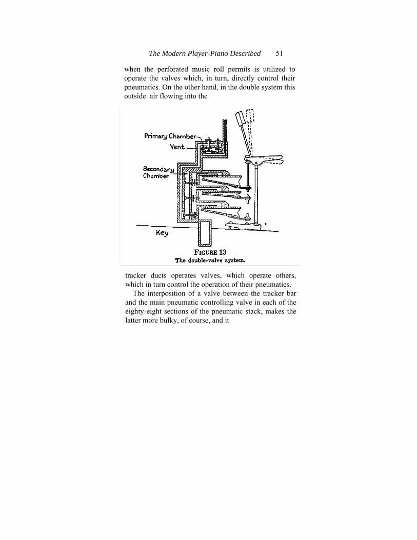
The Modern Player-Piano Described 51
when the perforated music roll permits is utilized to operate the valves which, in turn, directly control their pneumatics. On the other hand, in the double system this outside air flowing into the
tracker ducts operates valves, which operate others, which in turn control the operation of their pneumatics.
The interposition of a valve between the tracker bar and the main pneumatic controlling valve in each of the eighty-eight sections of the pneumatic stack, makes the latter more bulky, of course, and it
52 Piano Playing Mechanisms
is evident that the reasons which induced designers to utilize the more complex system must have been compelling. Actually, at the time of the general adoption of the double system these reasons were compelling, and a short statement of them here will be useful.
Reasons for Adopting the Double System,. In the first days of invention the problems which had to be met and mastered by the pioneer designers were many and varied. Among these, none was more perplexing than that of discovering materials which should combine lightness with airtightness. Moreover, the whole art was in a thoroughly immature state, and precedents were almost lacking. The proportions of working parts in respect to weight, dimensions, etc., had yet to be worked out. Naturally, in their efforts to produce something which would work satisfactorily and provide a reliable article for sale, the pioneers erred on the side of safety and so made all their parts extra large and heavy. When at the same time they searched for suitable airtight leathers and cloths, or for suitable methods of building wooden structures which should be airtight without being too bulky, they were again faced with the fact that there existed virtually no pertinent previous experience. Again, then, while experimenting to find the best of materials they were meanwhile obliged to put up with whatever they could get. All this meant bulk, clumsiness and weight.
The Modern Player-Piano Described 53
In view of these conditions, which may be well illustrated by recalling that twenty years ago a 65-note player-action occupied more space and was a good deal heavier, though far less powerful, than an 88-note action of today, it may readily be understood that one early and prime difficulty lay in the size and weight of the valves which control the playing pneumatics. Even with the comparatively large tracker ducts of the 65-note scale, which ran six to the inch, instead of nine to the inch as in the present 88-note scale, the amount of air which could be admitted through any one of them was often insuf-ficient to raise the corresponding valve rapidly enough for all conditions of playing, unless the pumping were very energetic and the working pressure consequently high. It was found, in other words, that the actions worked well on loud, but poorly on soft, playing. It occurred, therefore, to one inventor to interpose a small light valve between the tracker duct and the pneumatic controlling valve. The interposed valve might be light enough and small enough to rise instantly on even light pressure, and it could then uncover an air port large enough to operate the heavier controlling valve just as rapidly, even when under direct control of the tracker duct the heavy valve would have worked sluggishly.
The general adoption of this ingenious scheme was in the circumstances inevitable, so soon as its merits were tested, and so for some years the double
54 Piano Playing Mechanisms
system was supreme. If it has recently been again largely superseded by the single system the reason is equally easy to understand. Modern research, accumulated experience and commercial competition have combined to produce materials specially designed for the special purpose of player mechanism. In consequence, bulk has been diminished, parts are smaller, and there is less of wasted effort or space. It is now easily possible to make a single-valve action which will respond to the lightest pressure rapidly and surely. The special advantages which once made the double system a general favorite are therefore no longer unique.
Description of the Double System. Further reference to FIG. 13 will disclose the operations of the double system very clearly. The action, it will at once be seen, is divided into two parts, which, let us denominate, respectively, the primary chamber and the secondary chamber. The valves in the primary chest are known as primary valves, or "primaries," and two of them are shown in the drawing. To match the three pneumatics which are drawn in to illustrate the common method of banking them in the double-valve section, there should of course be three primaries, just as there are three secondaries; but it is customary to arrange the valves of the primary chest in two rows, for convenience sake, and it is impossible on a plane to show more than one in each row. It will be observed that one of these is shown with the pouch down and one with
The Modern Player-Piano Described 55
the pouch up, that is to say, with one at rest and one in operation. It will also be noticed that one secondary valve is shown at rest and one in operation, to correspond with the primaries.
Taking first the primary chest, we see that, as might have been anticipated, it consists of a chamber, on the floor of which are the pouches, and through the roof of which project the spindles of the primary valves. Obviously, if the chamber is connected by a tube or channel with the main bellows system it will lose part of the air contained in it and enter into a state of partial vacuum. In consequence, all the valves will assume the position shown by the right-hand primary valve in the drawing. The valves will rest over the pouches and their top buttons will be pressed down firmly upon the top of the external air entrance, so as to keep any external air from the chamber and also from the channel, which may be seen leading from under the top buttons down to the secondary chest. On account of the presence of a vent near each pouch, as may also be seen, the air in the tracker ducts (assuming the paper roll to be unperforated and the tracker ducts, therefore, all sealed) will also be partially exhausted through the vents, and its pressure consequently reduced below that of the atmosphere. The external air pressure above the top button will therefore be sufficient to hold that button down firmly.
In consequence of this no air can flow into the
56 Piano Playing Mechanisms
channel which leads down into the secondary chest. Hence, the air that may have been there originally will have partially escaped into the primary chest, there being a clear passage for it, as may be seen by examining the drawing. Unfortunately, the latter shows, and can show in the circumstances, only one channel from chest to chest, although there ought to be three shown, to correspond with the valves, and although, of course, there are actually eighty-eight. But we are looking at a sectional drawing which is supposed to give a view through one side, and consequently we can only see one channel. We must therefore imagine the others ranked side by side along the length of the chest. ( FIG. 13.) Now, taking the right-hand primary valve and considering it as in connection, per the channel, with the top secondary valve shown in the drawing, we see that so long as this primary shuts off any atmosphere from the secondary channel the air in the latter will be partially exhausted, and consequently will be unable to balance the atmospheric pressure which we observe operating against the outer disk of the secondary valve. Hence, the secondary valve will be kept pressed back so that its outer disk admits atmosphere to the pneumatic, while its inner disk shuts off the secondary chamber from the atmosphere. If the tracker bar remains completely sealed up, all the primaries will be down and all the secondaries pressed back, as described. Accordingly, all the pneumatics will be open to the
The Modern Player-Piano Described 57
atmosphere and will remain extended and at rest. Operation of the System. Suppose that the moving paper brings a perforation on its surface into register with one of the tracker ducts. Immediately the atmospheric pressure is restored in the primary channel (the vent, be it remembered, is too small to prevent this restoration against a continuous at-mospheric pressure). The primary pouch, therefore, is thrown upwards (see the left-hand primary in the drawing), for it is designedly made larger in area than the top primary button. The primary valve rises, and as its top button uncovers the air port above the secondary channel, its bottom disk seals up the chamber from the inrush of air above it. This air at once enters the secondary channel and restores the atmospheric pressure there. The secondary chamber is under reduced pressure from the operation of the main bellows, just as the pri-mary chamber is, and accordingly, the pressure of the atmosphere against the pouch (in the drawing, the middle one of the three in the secondary chest) pushes the valve forward and shuts off the atmo-sphere from the pneumatic by pressing the outer disk against the air port, while opening a connection between pneumatic and chamber by moving the inner disk away from its previous door-position. Hence the atmospheric pressure in the pneumatic is at once reduced by the leakage of the contained air out into the low-pressure region of the chamber and, accordingly, the atmospheric pressure against
58 Piano Playing Mechanisms
the outside of the pneumatic comes into play and pushes the pneumatic shut. This operates the piano action as before.
Reverse of the Operation. When the perforation has passed over and the tracker duct under consid-eration is again sealed, the flow of atmospheric air through the primary channel is stopped. Accord-ingly, the air trapped in this channel flows partly through the vent, reducing the pressure of the re-maining air until the atmospheric pressure on the top primary disk presses down the primary valve, shutting off the flow of atmospheric air from the secondary channel and allowing the air contained in the latter to exhaust partially into the primary chamber again. (See right-hand primary in drawing. ) Therefore, the atmospheric pressure in front of the outer disk of the secondary valve will press the latter back till the outer disk opens an atmospheric passage to the pneumatic and the inner disk again seals the chamber. The pneumatic at once fills with atmospheric air and opens up, assisted by the weight of the piano action to which it is connected, and also by a very light spring in its hinge. The piano action is thus released and the cycle of operations is complete.
The process may be repeated very rapidly. A good action, whether of single or of double type, will repeat at least ten times per second in favorable conditions. Hence the reader will understand that the time and space needed to describe the oper-
The Modern Player-Piano Described 59
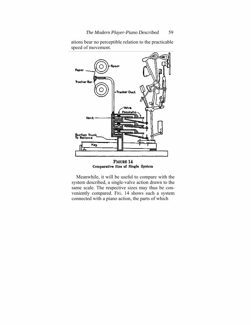
ations bear no perceptible relation to the practicable speed of movement.
Meanwhile, it will be useful to compare with the
system described, a single-valve action drawn to the same scale. The respective sizes may thus be con-veniently compared. FIG. 14 shows such a system connected with a piano action, the parts of which
60 Piano Playing Mechanisms
are drawn to scale with the parts of the single-valve mechanism.
Having thus described the physical operation of the action, which is exactly that of the single system with the additional movements required by the interposition of the primary valve, we shall go on to consider the details of construction in both systems, considering the questions of materials, methods, dimensions, etc.
Details of Construction — Pouches. It has been found by experience that the purposes of pouches are well served by the use of fine, soft kid leather. The pouches require to be completely airtight and yet be soft and flexible, so that they may continue to expand and relax under the influence of atmospheric pressure without breaking loose from their fastenings or becoming porous. With the last few years much work has been successfully done with a skin manufactured from the linings of animal intestines. This has been found to be successfully airtight, flexible and adaptable. The dimensions of pouches differ, of course, with requirements. The shape is always circular. The leather is cut so as to fit over a slightly smaller circular pit drilled in the floor of the chamber. It is fastened in place with glue. The primary pouches usually have a diameter of about three-quarters of an inch, while the secondaries are often one and one-quarter inches in diameter.
The primary valves themselves are commonly

The Modern Player-Piano Described 61
made by placing the required buttons, made of wood, upon a wooden spindle. It is necessary that the primaries should rise only through as short a distance as will allow a sufficient inflow of air. Common practice assigns to them a lift of very little more than one-sixty-fourth of an inch, uncovering a hole of one-quarter inch in diameter, through which passes the spindle of the valve, which is usually one-eighth inch in diameter. The resulting available area for the passage of air into the secondary channel is sufficient to move the circular secondary pouch with its diameter of one inch or more against the secondary valve's outer disk, of which the diameter does not usually exceed five-eighths of an inch.
The secondary valve itself commonly comprises a steel spindle, on which are threaded inner and outer disks made of a body of cardboard with leather on each face. The thickness should not exceed one-six-teenth of an inch. A light wooden button is attached to the end of the spindle nearest the pouch and rests in front of the latter at a distance of one-thirty-second of an inch. It is necessary to provide guide-slots for the outer end of the spindle so as to prevent any distortion of the movement from a straight line, and such guides are commonly made of fiber, bushed with piano-action bushing-cloth.
In single-valve systems a good deal of progress has been made in dispensing entirely with the guides, by making the spindles wide enough to
62 Piano Playing Mechanisms
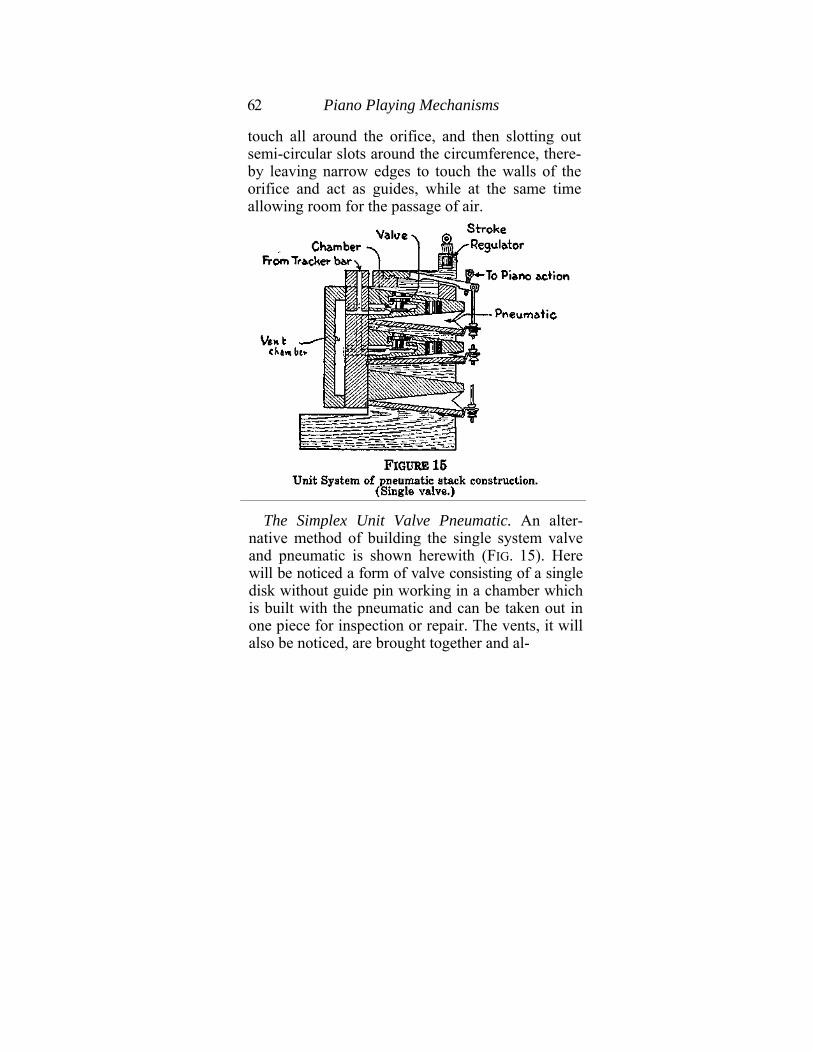
touch all around the orifice, and then slotting out semi-circular slots around the circumference, there-by leaving narrow edges to touch the walls of the orifice and act as guides, while at the same time allowing room for the passage of air.
The Simplex Unit Valve Pneumatic. An alter-
native method of building the single system valve and pneumatic is shown herewith (FIG. 15). Here will be noticed a form of valve consisting of a single disk without guide pin working in a chamber which is built with the pneumatic and can be taken out in one piece for inspection or repair. The vents, it will also be noticed, are brought together and al-
The Modem Player-Piano Described 63
lowed to open into a special chamber in front of the tracker ducts. This is the "Simplex" action.
Another unit system very well known is featured in the Gulbransen action; and there are still other variants which need not concern us here. The reader will have no difficulty in understanding any of them after he has mastered the considerations already set forth.
Continuing our survey we may remark in passing that vents are usually made by putting little brass cups drilled with No. 60 drill into small holes which, of course, are ranged in some position convenient for examination or cleaning. Sometimes celluloid disks are cemented over small holes drilled in similar positions (i. e.} between channel and chamber) and are pierced with holes of the same size. In some cases alternative schemes are used. The Kimball player action has all its vents (often called bleed-holes) arranged in one line in a separate chamber away from the valves. This chamber is connected with the pneumatic stack by a tube, and therefore the air in the channels leaks out constantly into this suction chamber just as if the vents were placed in the floor of the regular chamber. The intention in this case is to improve accessibility.
The important thing to remember is the function of the vents, namely, that they operate to allow atmospheric air to leak out into a reduced-pressure chamber, thereby reducing the pressure inside the
64 Piano Playing Mechanisms
tracker ducts, which have been sealed off by the paper from the atmosphere. Just how the vents are placed is therefore not so important as it might seem at first thought.
Details of Construction — Playing Pneumatics. It has already been pointed out, at least by impli-cation, that there is no need in a double-valve sys-tem for a vent in the secondary chest. The atmo-spheric pressure in the secondary channel is re-duced by leakage into the primary chamber when the primary valve is down.
In reference to the pneumatics themselves a great deal of variation as to size may be discovered in the practice of manufacturers, but it must be rem-embered that the limit of all experiments in this direction is to be found in the space requirements of the piano. It would perhaps seem that since the orifices opening into the pneumatics are nearly al-ways of the areas already indicated (i. e.} one-half square inch, or a very little more), the moving walls of the pneumatic should present to the atmosphere areas not exceeding four square inches. The actual dimensions of such pneumatics may be, therefore, 4"X1", 5"X13/16", or 4y2"X%"- Practice varies, as already stated, but the dimensions here given will be found satisfactory in nearly all cases.
The moving and fixed walls of the pneumatic are commonly made from superior lumber about three-thirty-seconds of an inch thick, and are joined by a clothing of rubber-impregnated silk cloth spe-
The Modern Player-Piano Described 65
cially made for the purpose. The intestinal material mentioned previously in connection with pouches has also been used successfully for clothing pneumatics. Maple is probably the very best possi-ble kind of lumber for building pneumatics, but other less expensive woods are commonly used.
Details of Construction — Reduced - Pressure Chambers. The walls of the chambers are made either of maple or of some combination of soft and hard woods. In most of the double-valve actions it is necessary to have the boards on which the pri-mary and secondary pouches rest easily removable. Accordingly, joints are carefully faced with buck-skin or similar leather in order to make them air-tight. It is very necessary either to make these boards of hard wood, against hard wood sides and backs, or else at least to have the sides into which go the fastening screws made of some good hard wood, such as maple, oak or ash.
Shellac is freely used to fill the pores of the wood in the sides, backs and covers of the chambers, and, in fact, wherever it is likely to be useful, as in the interiors of channels, and in other places where the airtightness of wood may be ensured by filling its pores.
The Roll Driving Mechanism. From the playing mechanism proper we may now turn to its comple-mentary apparatus, namely, that which is occupied in controlling the perforated music roll and ren-dering it useful for the purpose of playing music.
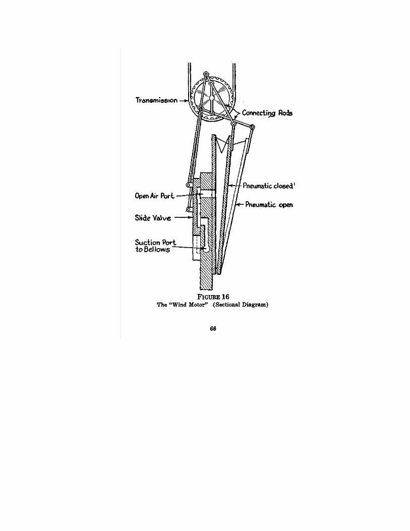
The Modern Player-Piano Described 67
The reader has seen on a previous page how the se-lection of the sounds to be produced by the piano action under the touch of the pneumatics is governed by the device of moving a continuous sheet of paper over a tracker bar, on which are ranged the eighty-eight ducts leading to the eighty-eight controlling valves. The paper is perforated so that the perforations arrive at their corresponding holes in the tracker bar in such order as may be necessary to produce the tones of some given piece of music. Obviously, then, the speed at which any composition is performed on the player-piano will be determined by the speed at which the paper is caused to wind from one spool to another over the tracker bar.
The roll of paper, as stated, is wound on a spool, which is placed, by means of suitable holes in its end flanges, upon two chucks. The loose end of the roll may be hooked to the take-up spool, which is on the other side of the tracker bar, and may then by suitable apparatus be wound on the take-up spool until its perforations have all passed over the tracker bar and the piece of music is completed. Such suitable winding apparatus must be devised so that its speed of rotation may be readily controlled, and it be started and stopped instantly, as desired.
The Wind Motor. The winding or turning engine commonly used in the player mechanism is known colloquially as a "wind motor," and is illustrated herewith (See FIG. 16) in a sectional dia-
68 Piano Playing Mechanisms
gram, which shows the principle and its application, according to a method commonly used and de-servedly popular. The whole apparatus, both in its diagramatic representation shown herewith and in the later illustrations which set forth various means of applying its power for the practical purposes described above, is eminently worth the most careful study. As a practical application of the principle of sub-normal pressures worked out to the most delicate susceptibility to control, the wind motor of the player mechanism stands quite in a class by itself.
If the reader will glance first at FIG. 16 and then at FIG. 17, he will perceive that the wind motor con-sists of a series of small bellows mounted in line, with the moving wall of each connected by means of a connecting rod to a crankshaft. Plainly, each of these bellows may be caused to collapse and expand alternately, and if the closing and expanding in each case be properly timed with reference to the similar operations of each of the others, the crankshaft will be steadily rotated and a motion conveyed to the take-up spool of the music roll through any suitable gearing.
The reader will likewise perceive that unless some source of power besides the main bellows sys-tem is to be provided, the power consumption of the wind motor must be very light indeed. The apparatus must run and perform its task of winding up a roll of paper at controllable speed, under
The Modem Player-Piano Described 69
a power consumption scarcely heavier than is read-ily exerted by drawing in one's breath. In fact, if one sucks with the mouth on the main suction port of any good player-piano wind motor, which has for the purpose of the experiment been detached from its connections with the bellows of the player mechanism, it will be found that the machine turns readily under this very feeble suction. In a word, the first requirement of a wind motor is to run on the lightest possible power consumption. The second requirement is that it shall be susceptible to the most delicate control. The first requirement owes its origin to the fact that the wind motor of the player mechanism is designed to run from power supplied by the main bellows, the capacity of which is strictly limited by the muscular strength of the average user of the instrument. Seeing that at best not more than half the average amount of effort put on the bellows can be spared for the wind motor's requirements, it is evident that these must be very modest.
The second requirement—that of susceptibility to delicate control—arises from the fact that in order to play music artistically with the player - piano there must be the freest possible ability at will to change instantaneously the speed of playing, since it is on the question of speed of movement at any moment that the possibility of delicate phrasing entirely depends.
This being clear, let us now examine in detail the
70 Piano Playing Mechanisms
working principles of the wind motor. FIG. 16 will reveal the matter very plainly.
We see there two pneumatics (out of a possible five or six in the complete apparatus), each of which is connected up to the crankshaft. One is apparently opening as the shaft and sprocket-wheel turn, and the other is obviously closing. In front of the engine are to be seen rods, fastened at one end to the shaft, and at the other to slide valves, one for each pneumatic. Each slide valve can slide so as either to cover or uncover a port leading into each pneu-matic.
How the Motor Works. Suppose the engine to be connected with the main bellows of a player-piano by means of the suction port, indicated in the draw-ing. From the position shown it is evident that one of the slide-valves covers both the suction port com-municating with the bellows and the port leading into one of the pneumatics, thus opening an air-way from that pneumatic's interior to the bellows. When, therefore, the latter are operated, a state of reduced pressure is set up; and atmospheric air trapped in the pneumatic now under observation, will flow into the suction port till the pressure in the pneumatic is equally reduced. In consequence, the pneumatic will collapse under the atmospheric pressure on its outer wall. This wall will move inwards and push the connecting rod, which in turn will rotate the crankshaft a part of a turn. The rotation of the crankshaft will push the slide-valve
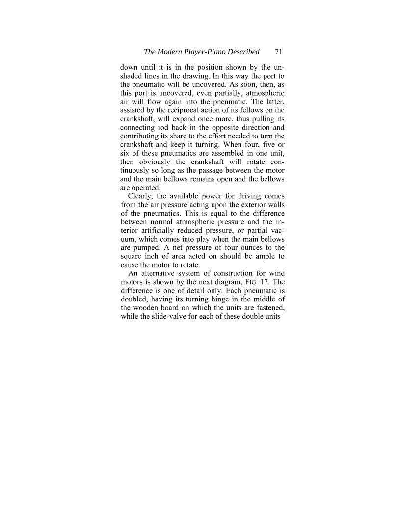
The Modern Player-Piano Described 71
down until it is in the position shown by the un-shaded lines in the drawing. In this way the port to the pneumatic will be uncovered. As soon, then, as this port is uncovered, even partially, atmospheric air will flow again into the pneumatic. The latter, assisted by the reciprocal action of its fellows on the crankshaft, will expand once more, thus pulling its connecting rod back in the opposite direction and contributing its share to the effort needed to turn the crankshaft and keep it turning. When four, five or six of these pneumatics are assembled in one unit, then obviously the crankshaft will rotate con-tinuously so long as the passage between the motor and the main bellows remains open and the bellows are operated.
Clearly, the available power for driving comes from the air pressure acting upon the exterior walls of the pneumatics. This is equal to the difference between normal atmospheric pressure and the in-terior artificially reduced pressure, or partial vac-uum, which comes into play when the main bellows are pumped. A net pressure of four ounces to the square inch of area acted on should be ample to cause the motor to rotate.
An alternative system of construction for wind motors is shown by the next diagram, FIG. 17. The difference is one of detail only. Each pneumatic is doubled, having its turning hinge in the middle of the wooden board on which the units are fastened, while the slide-valve for each of these double units
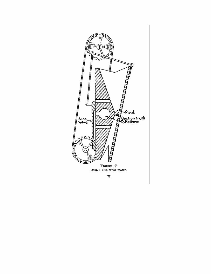
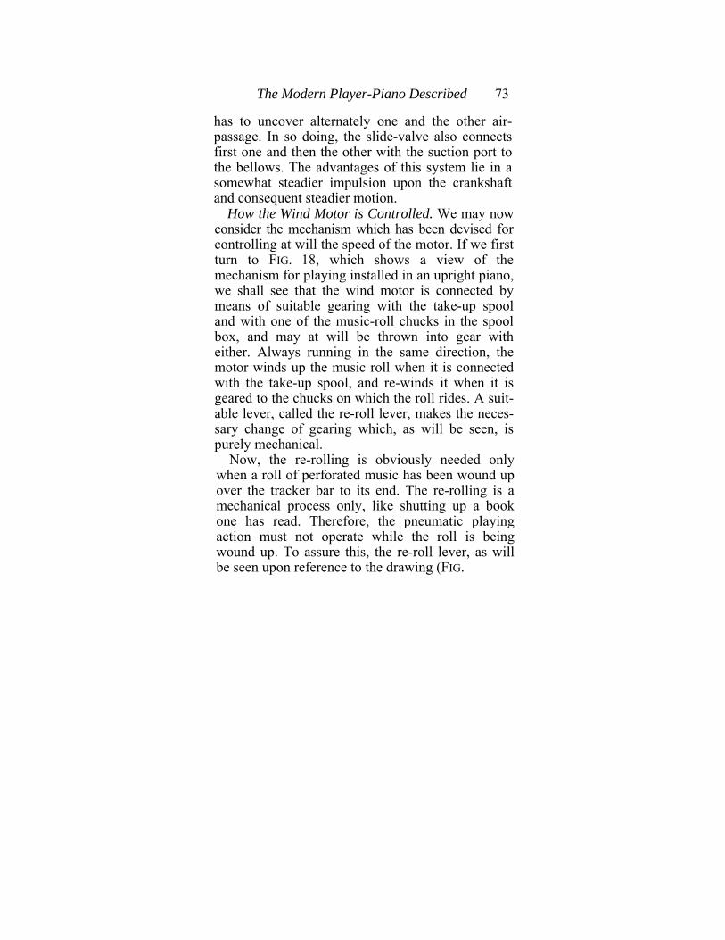
The Modern Player-Piano Described 73
has to uncover alternately one and the other air-passage. In so doing, the slide-valve also connects first one and then the other with the suction port to the bellows. The advantages of this system lie in a somewhat steadier impulsion upon the crankshaft and consequent steadier motion.
How the Wind Motor is Controlled. We may now consider the mechanism which has been devised for controlling at will the speed of the motor. If we first turn to FIG. 18, which shows a view of the mechanism for playing installed in an upright piano, we shall see that the wind motor is connected by means of suitable gearing with the take-up spool and with one of the music-roll chucks in the spool box, and may at will be thrown into gear with either. Always running in the same direction, the motor winds up the music roll when it is connected with the take-up spool, and re-winds it when it is geared to the chucks on which the roll rides. A suit-able lever, called the re-roll lever, makes the neces-sary change of gearing which, as will be seen, is purely mechanical.
Now, the re-rolling is obviously needed only when a roll of perforated music has been wound up over the tracker bar to its end. The re-rolling is a mechanical process only, like shutting up a book one has read. Therefore, the pneumatic playing action must not operate while the roll is being wound up. To assure this, the re-roll lever, as will be seen upon reference to the drawing (FIG.
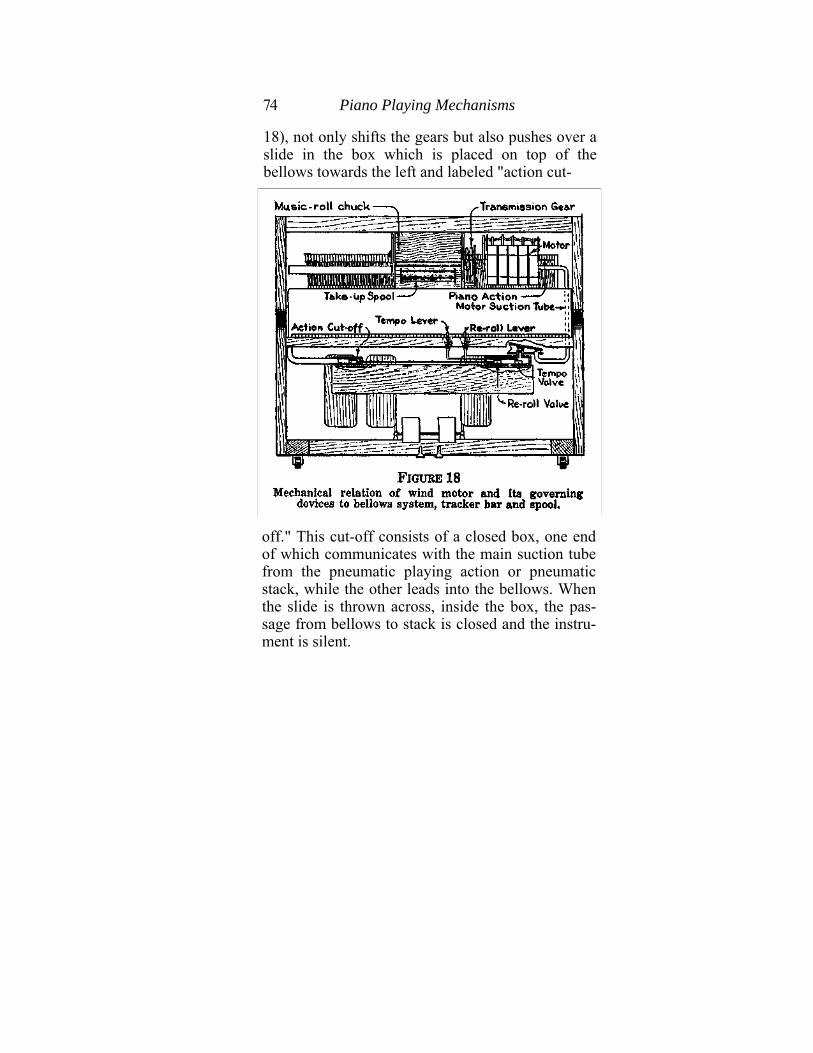
74 Piano Playing Mechanisms
18), not only shifts the gears but also pushes over a slide in the box which is placed on top of the bellows towards the left and labeled "action cut-
off." This cut-off consists of a closed box, one end of which communicates with the main suction tube from the pneumatic playing action or pneumatic stack, while the other leads into the bellows. When the slide is thrown across, inside the box, the pas-sage from bellows to stack is closed and the instru-ment is silent.
The Modem Player-Piano Described 75
Still another function must be performed by the re-roll lever. It is necessary, for convenience, that the operation of re-rolling shall be done with the utmost despatch, and so the motor must turn as fast as possible. In order to allow for this the re-roll lever, as will be seen from the illustration, performs also the third function of opening a special slide in the tempo-box, seen to the right of the bellows. This box contains the meeting place of the suction tube leading from the wind motor, with the corresponding passage into the bellows. This spe-cial slide, called the re-roll or re-wind valve, covers an orifice of extra large size.
Thus the re-roll lever does three things simulta-neously : it shifts gears, it cuts off the playing ac-tion, it opens a special speed valve for the motor.
Motor Speed Control. If the reader has paid close attention to the foregoing explanations he will have observed by now that the secret of changing the speed of the motor, when this is necessary, will be found in changing the size of the opening through which the air drawn in through the motor can pass into the bellows. The larger this passage-way is made the more rapidly will the motor turn, for the greater the quantity of air that can pass through from the motor to the bellows in any given length of time, the lower will be the interior pressure in the motor and the higher, consequently, the net operat-ing pressure. Hence, the more rapidly will the walls of the pneumatics in the motor move inwards.
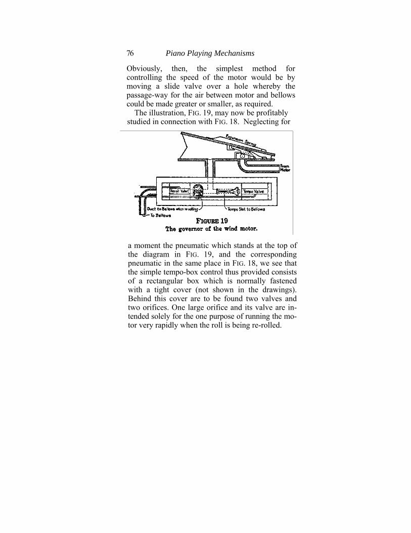
76 Piano Playing Mechanisms
Obviously, then, the simplest method for controlling the speed of the motor would be by moving a slide valve over a hole whereby the passage-way for the air between motor and bellows could be made greater or smaller, as required.
The illustration, FIG. 19, may now be profitably studied in connection with FIG. 18. Neglecting for
a moment the pneumatic which stands at the top of the diagram in FIG. 19, and the corresponding pneumatic in the same place in FIG. 18, we see that the simple tempo-box control thus provided consists of a rectangular box which is normally fastened with a tight cover (not shown in the drawings). Behind this cover are to be found two valves and two orifices. One large orifice and its valve are in-tended solely for the one purpose of running the mo-tor very rapidly when the roll is being re-rolled.
The Modern Player-Piano Described 77
These are marked in the drawing "Re-roll Valve" and "Duct to Bellows for Re-rolling." the others, carefully graduated in size, are intended to control the speed of the wind motor during playing. In the drawing these are marked "Tempo Valve" and "Tempo Slot." Of course, the re-roll (or re-wind) valve is never open when the wind motor is winding the roll forward. The re-roll lever (see above) takes care of that.
The Governance of Speed. If the bellows of the player-piano could always be completely depended upon, no other control than this would be required. But the demands made upon the capacity of the bellows, what engineers would call its "load," are constantly changing. When a succession of single notes is being played, the amount of air drawn into the playing action and drawn out to the bellows is smaller than when a series of chords is to be played. The amount of air which the bellows have to handle is therefore continually changing, and naturally there is a continual corresponding variation in the net working pressure at any moment available. Moreover, the action of the player-pianist in playing tends to accentuate this constant irregularity since, in the nature of the case, he must continually vary his foot action on the pedals in order to obtain shades of loudness or softness, sudden accentu-ations, or stress. Therefore, it is obvious that the mere opening or closing of a valve over an orifice could only maintain the motor at a required speed
78 Piano Playing Mechanisms
if the series of unpredictable changes in working pressure could be constantly compensated by mak-ing from moment to moment the most delicate changes in the size of the orifice. To do this by manipulating the slide valve is not impossible, but it would be very difficult.
Of course, it is not desired to maintain the motor at a constant speed. On the contrary, the skilled player-pianist is himself constantly varying the speed of his motor for purposes of pause, accelera-tion, stress, etc.; but he wishes to be assured that when he places the tempo lever (and hence the tempo valve) in a given position, the motor will run at a corresponding speed until the lever is shifted again. If he could never know what this speed was to be for any position of the tempo lever he could never make delicate changes in speed for the pur-pose of playing.
We therefore have recourse to the ingenious de-vice shown in detail in FIG. 19 and indicated in FIG. 18. This is commonly called a "tempo governor." The Italian word "tempo" is used in musical science to represent speed of movement, and the use of the word here is therefore admissible.
Details of Tempo Governor. This governor is in principle simply an automatic arrangement for making that delicate series of changes in the size of an orifice, to which attention was directed a moment ago. Examination of the diagram will dis-close the facts immediately.
The Modem Player-Piano Described 79
It will be seen that the suction tube from the wind motor is led into a pneumatic, which is provided with an expansion spring, where it is maintained normally in an open or expanded condition. Inside this pneumatic is a block which stands above and covering the tube from the motor, so that the air which comes down this tube must emerge through the hole in this block. Over this hole slides a jack-knife valve which is pressed downwards always by a small spring, while at the same time its free end is in contact with the moving wall of the pneumatic. If the wall of the pneumatic moves inwards the jack-knife valve will make a corresponding movement and will more completely cover the hole in the block. In fact, if the pneumatic collapses far enough the jack-knife valve will close the orifice in the block completely and thus entirely shut off power from the motor. At the other end of the pneumatic is the tube running into the tempo box.
How Tempo Governor Works. It is evident that the quantity of air passing from motor to bellows, through the governor and the tempo box, must always depend upon the size of the hole in the block as well as upon the position of the tempo valve. If the spring of the governing pneumatic be set at a strength of, say, six pounds, and if this be equiva-lent to a pressure per square inch of surface on the pneumatic's moving wall of, say, 4 ounces, then plainly the governing pneumatic will remain open
80 Piano Playing Mechanisms
so long as the net working pressure as determined by the bellows does not exceed this. If, however, it does exceed this, as by reason of the player-pianist desiring and obtaining extra power for his playing purposes, then the moving wall will be pressed inwards, owing to the corresponding fall in the interior pressure, and the hole in the block will be partially covered by the jack-knife valve. That is to say, the rapidity of motion of the air towards the bellows will have been increased, but simultaneously the passageway through which the air must move will have been correspondingly di-minished. The net result will therefore be un-changed. The motor thus will continue to run at its original speed (according to the position of the tempo lever and valve), irrespective of changes in the general net working pressure.
Obviously, the governing pneumatic should be set to close slightly as soon as the bellows start working, because it may be necessary to have it ex-pand, as well as collapse, in order to meet certain conditions. For instance, if the bellows pressure suddenly drops, as when the player-pianist wishes to play a series of single notes very softly, the rise of the interior pressure, together with the power of the expansion spring, will overbalance the atmo-spheric pressure and force the pneumatic to expand, thus enlarging the passageway and compensating for the fall in the rapidity of air motion through the governor. It is best, therefore, in order
The Modern Player-Piano Described 81
to allow for this requirement, to regulate the strength of the expansion spring so that the pneu-matic shall always be in partial collapse when the bellows are working at their average capacity. Thus both tendencies, towards speeding and towards dragging, will be overcome automatically.
In this ingenious manner the motor is maintained at constant speed for any given position of the tempo lever, irrespective of any ordinary calls upon the air-moving capacity of the bellows.
For simplicity's sake in these last two illustrations the tempo-box is shown with the re-wind (re-roll) valve connected directly to the governing pneumatic. Often, however, it is possible to arrange for this tempo valve to open an orifice directly into the bellows so that the motor speed, on re-rolling, may be even greater, which is highly desirable.
All systems for governing the speed of motors are designed on this automatic principle, which, indeed, is capable of many embodiments, and also of many other applications, as we will see when we come to consider reproducing pianos.
Tracking Devices. It is scarcely necessary to go into detail in reference to the tracker bar and its accessories. FIG. 18 shows the connections plainly, and almost everything else is self-evident.
One point, however, demands immediate atten-tion. A great deal of ingenuity has been expended, and much patent litigation has resulted from the expenditure, in the effort to produce a mechanism
82 Piano Playing Mechanisms
which shall automatically cause the moving paper always to register correctly with the tracker bar. A moment's thought will show that when the total width of the tracker bar is only a little more than twelve inches, and the eighty-eight perforations in it consequently are spaced at the rate of nine to the transverse inch, the travel of the paper over the bar must be most carefully managed if the perforations are always to register with their corresponding perforations on the bar. A very slight shift to one side or the other will be fatal. Numerous methods have consequently been devised for the purpose of taking care of this need.
The simplest of all is a mechanical arrangement for shifting the tracker bar from right to left when-ever the paper does not register correctly. The illustration (FIG. 20) shows the principle. When the paper does not register correctly, for any reason, the tracker is caused to shift laterally by means of the finger-controlled knurled nut, which works on a threaded rod on which the shell of the tracker bar rides.
Transposition. An interesting advantage acces-sory to a simple scheme like this lies in the fact that by shifting the tracker bar sufficiently far to the right or left the player-pianist may move all the perforations in the bar one step up or down the scale. Thus, by shifting the bar along to the right, that is, towards the treble side of the piano, the pitch of the whole playing is lowered, since the low-

The Modern Player-Piano Described 83
est perforation on the bar, sounding the lowest note on the piano, now corresponds with the lowest but one on the paper. Likewise, the highest perforation on the extreme right-hand side of the paper corre-sponds with the perforation one below the highest
on the bar. The pitch may be raised by shifting the bar far enough to the left to bring the highest per-foration on the paper in register with the highest but one on the bar, and so on. In fact, some tracker bars are arranged to shift two or three perforations either way, with corresponding advantages in transposition. For accompanying the voice or solo instruments this advantage is very great, and largely adds to the usefulness of the player-piano.
Causes of Defect in Tracking. But there has al-ways been a demand for a tracker adjusting device
84 Piano Playing Mechanisms
which will work quite automatically and without requiring the attention of the human player-pianist. The general principle of the many mechanisms which have been worked out for this purpose is easy to understand, and is herewith described.
Defects in the tracking of music rolls, that is to say, in the registration of their perforations with the perforations corresponding in the bar, are mainly due to defects of the paper itself. Paper is a sub-stance eminently adapted for the purpose of re-ceiving perforations, and equally suitable for con-venient manipulation in the form of spooled rolls, but it is singularly hygroscopic, soaking up mois-ture with the greatest avidity. Therefore, it con-stantly swells or shrinks, according to the atmo-spheric condition in which it is placed. When it is laden with moisture, and consequently swollen, it does not register correctly with the tracker bar. Again, the most careful methods of manufacture cannot be automatically perfect, and the best paper will sometimes be slightly twisted or uneven in places. Hence, with the very small margin allowed for imperfect travel, the possibility of the paper sliding from side to side or requiring in some way to be readjusted is from moment to moment very great.
All automatic systems of adjustment must there-fore be controlled by the action of the paper itself in the course of its travel over the bar.
Principle of Automatic Tracking. In the at-
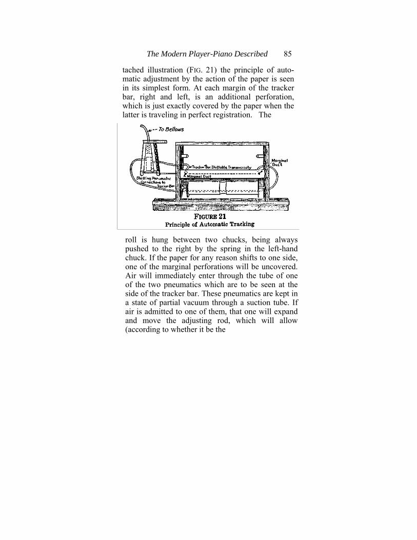
The Modern Player-Piano Described 85
tached illustration (FIG. 21) the principle of auto-matic adjustment by the action of the paper is seen in its simplest form. At each margin of the tracker bar, right and left, is an additional perforation, which is just exactly covered by the paper when the latter is traveling in perfect registration. The
roll is hung between two chucks, being always pushed to the right by the spring in the left-hand chuck. If the paper for any reason shifts to one side, one of the marginal perforations will be uncovered. Air will immediately enter through the tube of one of the two pneumatics which are to be seen at the side of the tracker bar. These pneumatics are kept in a state of partial vacuum through a suction tube. If air is admitted to one of them, that one will expand and move the adjusting rod, which will allow (according to whether it be the
86 Piano Playing Mechanisms
right or left perforation which is involved) the right-hand chuck either to slide to the right or to push to the left. In either case the paper is shifted till the uncovered hole is again covered and the paper restored to its proper registration.
This simple principle has been embodied in various forms, all of which are more elaborate than the rudimentary mechanism here described. In practice, certain difficulties emerge which do not appear on the face of any description of the principle. For one thing, it is necessary that the mechanism should respond to the very slightest shifting of the paper, while, on the other hand, the actual motion of adjustment imparted to the paper must be slow and gentle in all circumstances. A sudden readjustment would probably throw the paper too far towards the opposite position and cause mal-adjustment in the other direction. It is therefore necessary that the mechanism be both very sensitive and very deliberate.
A very well known method of obtaining this needed result is found in the adjusting device used by the Standard Pneumatic Action Company, which is chosen because it represents very well the attempt to satisfy the two requirements mentioned, by means of special precautionary devices built into the mechanism. The illustration (FIG. 22) shows clearly what is meant.
Standard Pneumatic Tracking System. It will be observed that the tracker bar is provided with

The Modern Player-Piano Described 87
four marginal perforations, two on each side, so spaced that they form two pairs—one outer and one inner pair. The outer pair cares for paper rolls of ordinary widths, and the inner pair for the lesser widths which are occasionally met with. Each perforation connects with a tube running to the tracking device.
When the music roll is tracking "true," the edges of the paper will just cover both the inner and the outer marginal perforations in the tracker bar. This is shown in the illustration (FIG. 22), which also discloses the fact that when all these perforations in the bar are covered, the pneumatics which do the shifting are connected pneumatically with the suction leading into the pneumatic stack, or otherwise connected directly or indirectly with the main bellows.
Now be it understood clearly, as the illustration shows, that when a music roll is inserted between its chucks, the spring in the left-hand chuck tends constantly to push the roll over to the right. As will be seen, at the end of the right-hand chuck is a cam connected by a lever system to the shifting pneumatics. Since the roll normally bears against this cam all the time, it is plain that if any movement be imparted to this cam in an upward direction, it will force the roll towards the left. If it be moved downward, the roll will again press towards the right.
The outer perforations are numbered in the illus-tration, 1 and 4. The inner perforations are 2 and 3.
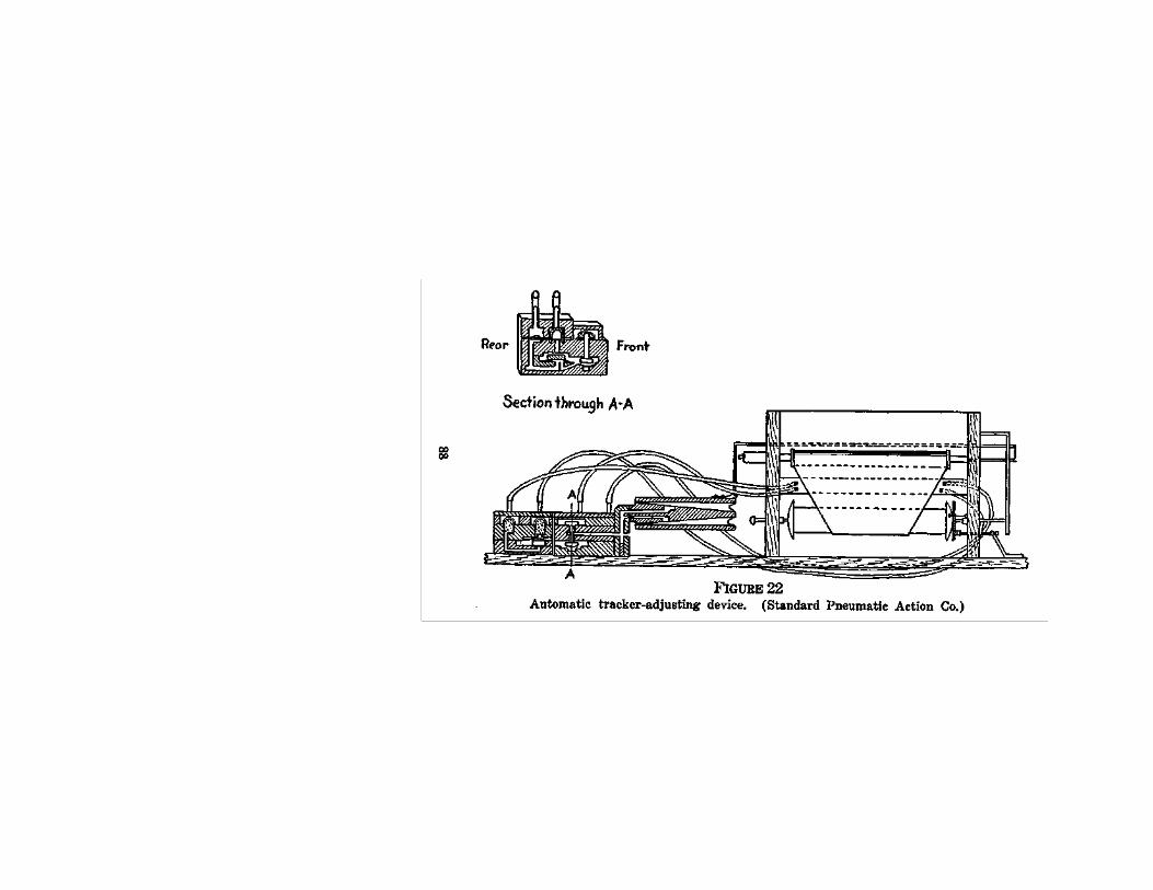

The Modern Player-Piano Described 89
Let us entirely ignore these last for the time being. Now consider perforation No. 1. As has just been said, when all the perforations are kept closed be-cause the paper is running true over the tracker bar, the pneumatics are both in a state of partial vacuum. These pneumatics are connected together by a lever, as shown, and so neither of them can move until the pressure is disturbed in one or the other. So long as both are at the same reduced pressure they are balancing each other and will no more move than they would if both were filled with air and similarly connected. The whole mechanism is therefore now in equilibrium.
Suppose, however, that the paper for some reason is shifted over to the right. Hole No. 1 in the bar is then uncovered. (Assume throughout that the play-er-piano is being pedaled.) At once atmospheric pressure is restored in tube No. 1. This at once re-stores atmospheric pressure in the tube leading from tube No. 1 into the valve box, and so also under the valve block which rests upon a pouch immediately at the end of the interior tube. Since the atmospheric pressure has been restored in this tube the valve block rises with the rising of the pouch. The valve block is only intended to shut off the parts connected with the inner perforations Nos. 2 and 3, which are not needed in ordinary cir-cumstances. But when the pouch rises it uncovers another passage at the side of the first one, a pas-sage which it has been keeping closed. This passage
90 Piano Playing Mechanisms
at once receives air at atmospheric pressure from the first tube, so that the large valve at the front of the valve box (shown to the right in the illustration) is immediately thrown upward. Atmospheric air is thus admitted into the pneumatic which corresponds with tube No. 1. This pneumatic fills with atmospheric pressure and forces the other one along with it. The lever system moves, the cam rises, and the music roll is forced to the left again.
The hole No. 4, on the opposite end of the tracker bar, is connected up with a set of valves of the same kind exactly. These operate in the same way whenever the paper shifts towards the left. Likewise, the valve box is provided with screens to protect it from lint or paper dust drawn in. The connection between pneumatics and valves is made very small, in order that the movements of the former may be performed slowly and deliberately. The whole principle may be summarized by saying that the operation of the valves is instantaneous, but of the pneumatics deliberate. In this way it is assured that there shall be no abrupt shifting which may do more harm than good.
It is only necessary to allude briefly to the inner perforations, for they are very seldom used. If a roll should be of less than standard width the two outer perforations would remain uncovered, and thus the two shifting pneumatics would be filled with atmospheric air all the time. They would, of
The Modern Player-Piano Described 91
course, balance each other. If one of the inner per-forations should also be uncovered, the atmospheric pressure, restored in its corresponding tube, would throw down the first valve block described above (which, of course, has been kept thrown up by the fact of its own outer perforations being open continuously) and thus would cause the large valve to drop, shutting off air from the corresponding pneumatic and causing its interior pressure to be reduced. Thus, the balance will be disturbed between the two pneumatics, and the lever system will be put into motion, with anticipated results.
Hammer Rail Control. In order to play expressively the player-pianist must have control over the ordinary accessory expressive devices of the piano, which are the soft (hammer-lifting) and the forte (damper-lifting) pedals. These cannot be manipulated by the feet when the player mechanism is being used, and it is therefore necessary to adapt them to be controlled by the hands of the player-pianist. Now, the soft-pedal device is better adapted for the player-piano when it is divided into at least two sections, so that the hammers may be lifted nearer to the strings by divisions. This refinement gives valuable assistance in subduing an accompaniment against a melody. It is a simple matter to lift the hammers by swinging the hammer rail through a lever connection operated by the fingers. To divide the hammer rail into two parts and have each half swung separately by a separate lever is also equally
92 Piano Playing Mechanisms
a simple matter. Usually, however, for purposes of convenience this is done pneumatically as follows:
FIG. 23 shows a section of the piano action and a portion of the key-bed. Sunk in the bed is a control button which closes or opens a hole leading into a tube which runs to a pneumatic and valve unit situated above the hammer rail. Usually, as said above, there are two of these sets—one at each end of the hammer rail—each controlling one-half of the hammer rail, and itself regulated by its indivi-dual control button.
It will be seen that the unit is connected by means of a suction tube with the vacuum-producing parts of the player action. When these are working and the button is at rest, the valve is pressed down on its seat and the atmosphere reaches the interior of the pneumatic. When, however, the button is depressed, atmospheric air enters the tube which has been opened, throws up the valve and causes the pneumatic to collapse, which it immediately does, moving the hammer rail, which is pivoted on swing hooks, and causing it to describe the arc of a circle, bringing the hammers nearer to the strings. The illustration shows the process clearly.
By means of this simple device either the bass or the treble half of the hammer line, or both, by finger pressure on the buttons, may be brought nearer to the string, thus introducing a softening effect.
The Damper Control. Even more important than this is an effective control of the damper line. The
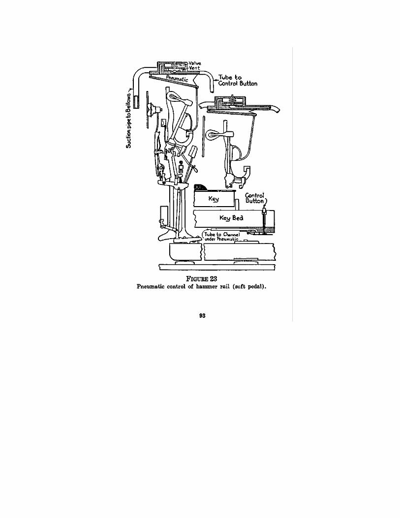
94 Piano Playing Mechanisms
damper pedal of the pianist furnishes the weapon for his most subtle effects. The property which the piano possesses of resounding, when its strings have been opened to vibration, the tone or tones last produced on it, is so valuable that it is often referred to as "the soul of the piano." Unfortunately, the fact that this process of drawing the dampers from the strings has a loudening effect, has led to the deplorable habit of thinking and speaking of the device as the "loud pedal." Of course, its true function is not to "louden" but to sustain and color the piano's tones.
The simplest and best way of controlling this effect when the player mechanism is in use is by direct lever connection from finger lever to the damper lifting rod which runs from the damper pedal of the piano to the piano action. So simple an arrangement needs no illustration.
A pneumatic device, however, is much used. It has been largely adopted through the insistence by retail music merchants that the owner of the player-piano shall have no special call made on his intelligence. This pneumatic device, therefore, requires explanation, especially as in its later development it affords valuable means for regulating the damper control through the music roll itself.
The illustration shows the facts. In FIG. 24 is seen a section of the piano action, with the usual lift rod connected with the damper swing rail, of which one end can be seen. A pneumatic is connect-
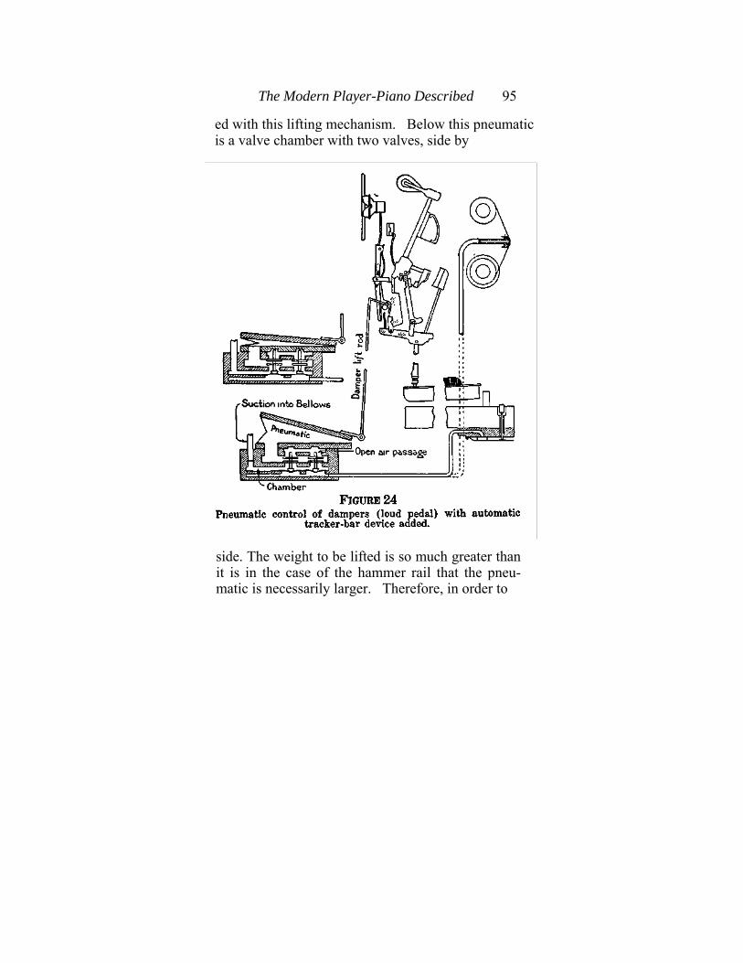
The Modern Player-Piano Described 95
ed with this lifting mechanism. Below this pneumatic is a valve chamber with two valves, side by
side. The weight to be lifted is so much greater than it is in the case of the hammer rail that the pneu-matic is necessarily larger. Therefore, in order to
96 Piano Playing Mechanisms
obtain reasonable rapidity of operation the pneu-matic is provided with two valves, both of which open into a tube running to a button on the key-bed and also to a perforation placed at the left-hand margin of the tracker bar.
Setting aside for the moment the last, which, of course, may be thrown in or out of operation by a switch placed in any convenient position, we ob-serve that when the player-piano is in operation the valve chamber is subjected to suction, whereby the valves are held down and the pneumatic is held open. When the button is depressed, however, the valves are thrown up (the two together in this case) and the pneumatic at once collapses, lifting the rod and swinging the damper line from the strings. When the button is released this process is reversed.
Automatic Damper Control. Now, in order to help the unskilled owner of a player-piano to obtain good pedal effects, it has come to be the custom to place special controlling perforations at the left margin of the music roll to throw on and off the damper device. This is easily done by means of a small addition to the arrangements already de-scribed. As will be seen from the same illustration (FIG. 24), the moving paper acts as a controlling valve in place of the button. When a hole in the paper registers with the tracker duct the pneumatic collapses and the dampers are raised from the strings. When the hole passes over, the duct is again sealed and the operation is reversed. This
The Modern Player-Piano Described 97
process corresponds to the depression and release of the finger button, or of the right-hand pedal of the piano by the pianist.
This automatic roll-controlled feature may be used alongside the button arrangement and may be cut out when not needed by a simple device for closing the passage between pneumatic and tracker bar at any convenient place.
Pneumatic Governance of Playing Power. Ex-pression control, however, is not ended with devices of this sort. In the effort to facilitate the attainment of contrast, tone-color and accent, various pneumatic devices have been worked out, all of which are primarily intended to give to the player-pianist the power to make changes in the dynamic intensity of his playing, more suddenly than can be done by means of the pedal work.
When combined with appropriate manipulation of speed, dampers and pedals, the mechanical problems of attaining tonal variety, contrast and color may be reduced to terms of change from low to high playing power, that is to say, from high to low internal pressure, corresponding with change from lower to higher effective atmospheric pressure. These changes are most naturally and effectively made by the player-pianist through the agency of the pedals of the player-piano, but this agency is not in all cases sufficient. It does not suffice, that is to say, when the changes are required to succeed each other more rapidly than the pedals can be
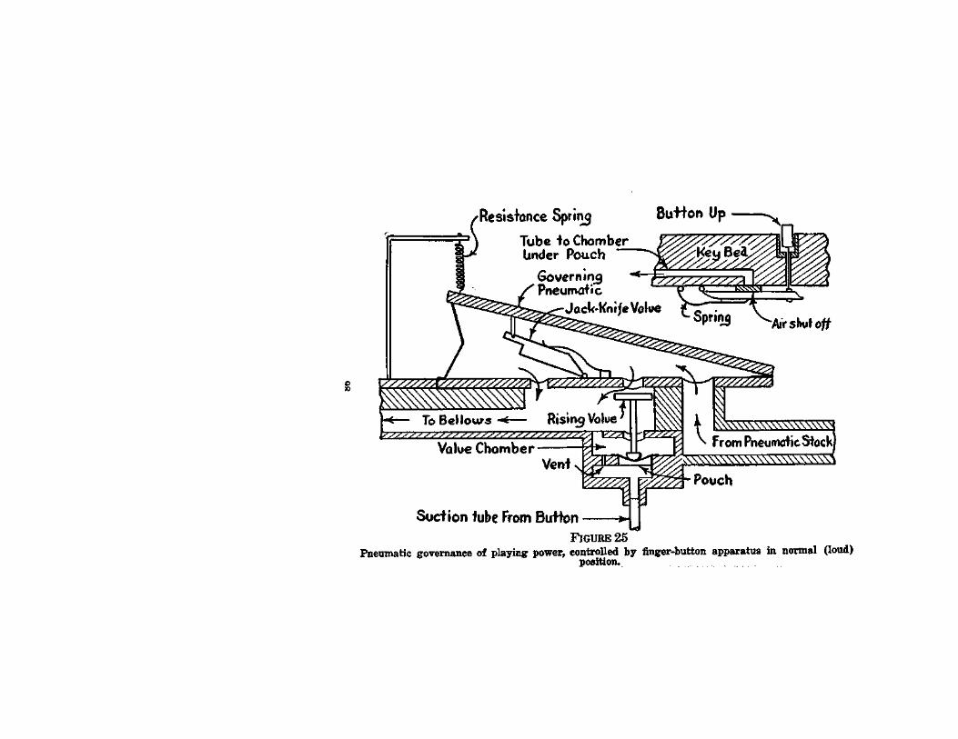
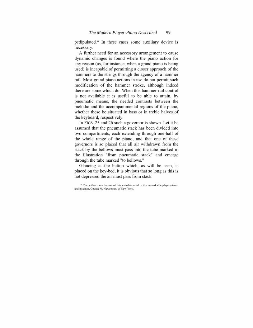
The Modern Player-Piano Described 99
pedipulated.* In these cases some auxiliary device is necessary.
A further need for an accessory arrangement to cause dynamic changes is found where the piano action for any reason (as, for instance, when a grand piano is being used) is incapable of permitting a closer approach of the hammers to the strings through the agency of a hammer rail. Most grand piano actions in use do not permit such modification of the hammer stroke, although indeed there are some which do. When this hammer-rail control is not available it is useful to be able to attain, by pneumatic means, the needed contrasts between the melodic and the accompanimental regions of the piano, whether these be situated in bass or in treble halves of the keyboard, respectively.
In FIGS. 25 and 26 such a governor is shown. Let it be assumed that the pneumatic stack has been divided into two compartments, each extending through one-half of the whole range of the piano, and that one of these governors is so placed that all air withdrawn from the stack by the bellows must pass into the tube marked in the illustration "from pneumatic stack" and emerge through the tube marked "to bellows."
Glancing at the button which, as will be seen, is placed on the key-bed, it is obvious that so long as this is not depressed the air must pass from stack
* The author owes the use of this valuable word to that remarkable player-pianist and inventor, George M. Newcomer, of New York.
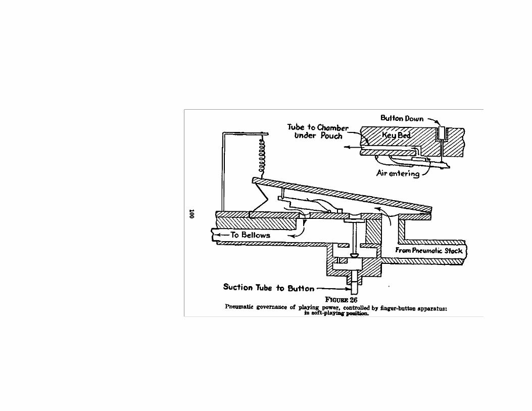
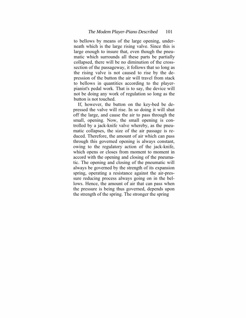
The Modem Player-Piano Described 101
to bellows by means of the large opening, under-neath which is the large rising valve. Since this is large enough to insure that, even though the pneu-matic which surrounds all these parts be partially collapsed, there will be no diminution of the cross-section of the passageway, it follows that so long as the rising valve is not caused to rise by the de-pression of the button the air will travel from stack to bellows in quantities according to the player-pianist's pedal work. That is to say, the device will not be doing any work of regulation so long as the button is not touched.
If, however, the button on the key-bed be de-pressed the valve will rise. In so doing it will shut off the large, and cause the air to pass through the small, opening. Now, the small opening is con-trolled by a jack-knife valve whereby, as the pneu-matic collapses, the size of the air passage is re-duced. Therefore, the amount of air which can pass through this governed opening is always constant, owing to the regulatory action of the jack-knife, which opens or closes from moment to moment in accord with the opening and closing of the pneuma-tic. The opening and closing of the pneumatic will always be governed by the strength of its expansion spring, operating a resistance against the air-pres-sure reducing process always going on in the bel-lows. Hence, the amount of air that can pass when the pressure is being thus governed, depends upon the strength of the spring. The stronger the spring
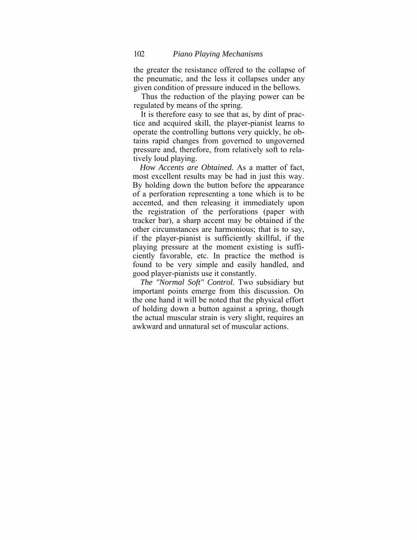
102 Piano Playing Mechanisms
the greater the resistance offered to the collapse of the pneumatic, and the less it collapses under any given condition of pressure induced in the bellows.
Thus the reduction of the playing power can be regulated by means of the spring.
It is therefore easy to see that as, by dint of prac-tice and acquired skill, the player-pianist learns to operate the controlling buttons very quickly, he ob-tains rapid changes from governed to ungoverned pressure and, therefore, from relatively soft to rela-tively loud playing.
How Accents are Obtained. As a matter of fact, most excellent results may be had in just this way. By holding down the button before the appearance of a perforation representing a tone which is to be accented, and then releasing it immediately upon the registration of the perforations (paper with tracker bar), a sharp accent may be obtained if the other circumstances are harmonious; that is to say, if the player-pianist is sufficiently skillful, if the playing pressure at the moment existing is suffi-ciently favorable, etc. In practice the method is found to be very simple and easily handled, and good player-pianists use it constantly.
The "Normal Soft" Control. Two subsidiary but important points emerge from this discussion. On the one hand it will be noted that the physical effort of holding down a button against a spring, though the actual muscular strain is very slight, requires an awkward and unnatural set of muscular actions.
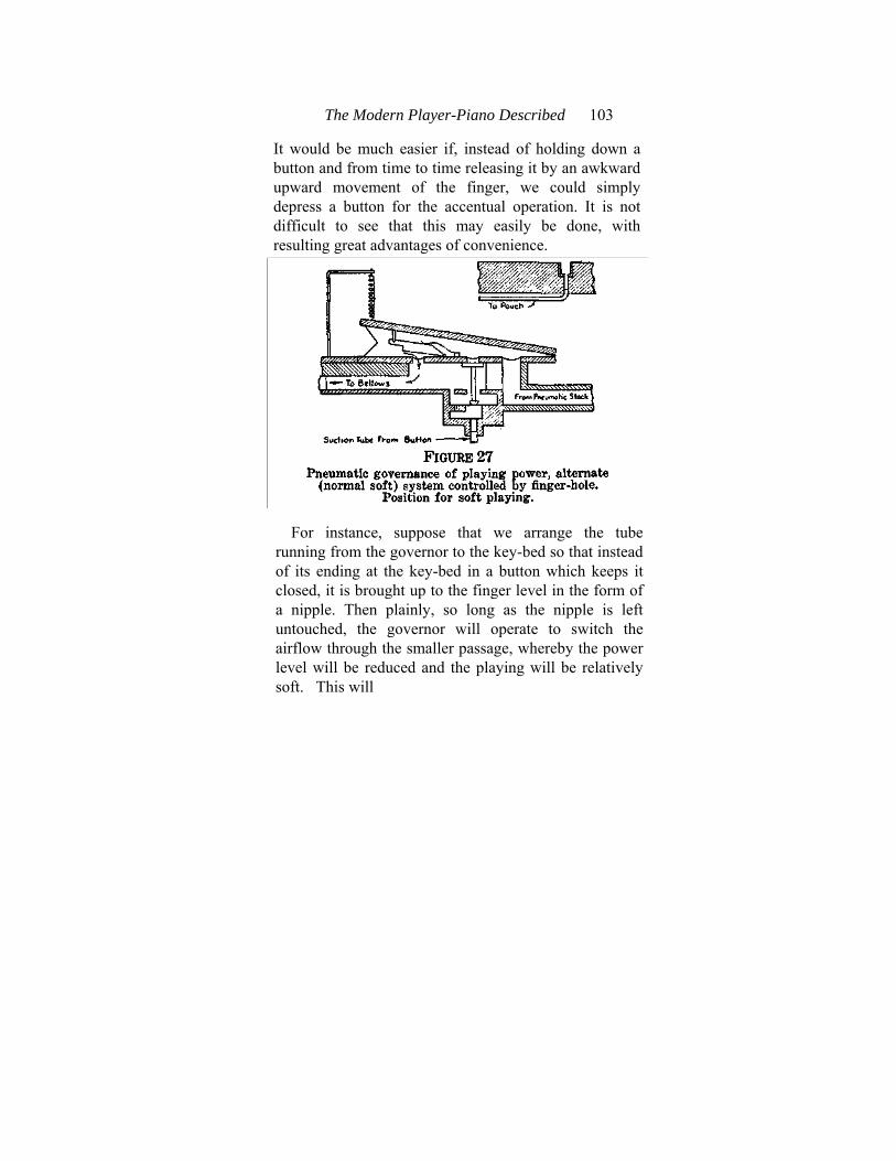
The Modern Player-Piano Described 103
It would be much easier if, instead of holding down a button and from time to time releasing it by an awkward upward movement of the finger, we could simply depress a button for the accentual operation. It is not difficult to see that this may easily be done, with resulting great advantages of convenience.
For instance, suppose that we arrange the tube running from the governor to the key-bed so that instead of its ending at the key-bed in a button which keeps it closed, it is brought up to the finger level in the form of a nipple. Then plainly, so long as the nipple is left untouched, the governor will operate to switch the airflow through the smaller passage, whereby the power level will be reduced and the playing will be relatively soft. This will
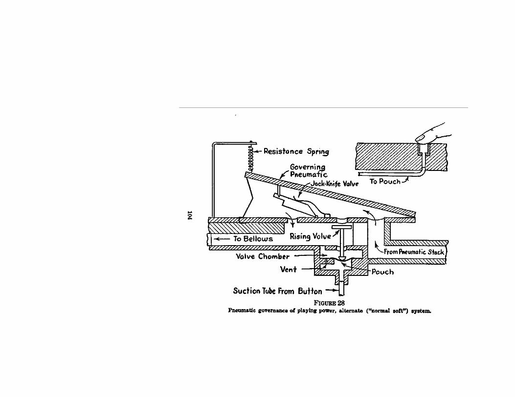
The Modem Player-Piano Described 105
now be the normal condition of affairs. The playing will be "normally soft," and no amount of foot work on the bellows will have any effect upon its loudness. But the moment the finger is placed on the nipple, shutting off the atmospheric flow into the tube (See FIG. 28), the operation of the governor will be reversed and the air flow will proceed through the main passageway, thus responding in-stantly to whatever may be the vacuum conditions obtaining in the main bellows.
Trial will at once convince the inquirer that it is much easier and more convenient to drop the finger down from a position at which the muscles are not being strained than to raise it from a position where it is being compelled to hold down even a very slightly resisting object. The fact that the reversed control here shown involves a "normal soft" condition of playing is of no practical importance since, of course, the finger is laid on the open nipple whenever it is desired to use the bellows flexibly.
This very small matter has been described fully because it gives rise to another which will become very important when we undertake to investigate automatic expression. The same principle which has here been set forth may be applied, precisely as was noted in connection with the pneumatic control of the damper lift (See FIG. 24), to obtain automatic accentuation in connection with appropriate perforations in the margins of the music roll. A simple drawing and a short explanation will

The Modern Player-Piano Described 107
suffice to explain this and to prepare the reader's mind for the more important discussions which will come later.
Principle of Automatic Dynamic Control. In FIGS. 29 and 30 will be seen the principle very simply set forth. The moving paper is provided at the proper points with very small marginal perforations. These register with a tracker duct connected by a tube to a pneumatic governor. So long as the paper seals the duct the pneumatic, as may be seen in the illustration, causes all air to flow through the smaller passageway. Thus, the playing is normally soft. When a marginal perforation registers with the duct the atmospheric inflow operates the valve and causes the main air flow to pass through the large passageway, thus giving the full power at the moment available. It must be evident that this method is simply the button method (See FIGS. 25-26) reversed, i. e., it is the finger-hole method (See FIGS. 27-28), or normal soft method described above, with the moving paper and marginal tracker ducts substituted for the fingers, buttons, or finger-holes.
The specially named expression control devices found in many player actions operate according to the principles here explained. When we come to consider the later developments of automatic expression we shall see how, from these relatively simple methods, have been worked out a most elaborate set of devices in various forms for obtaining,
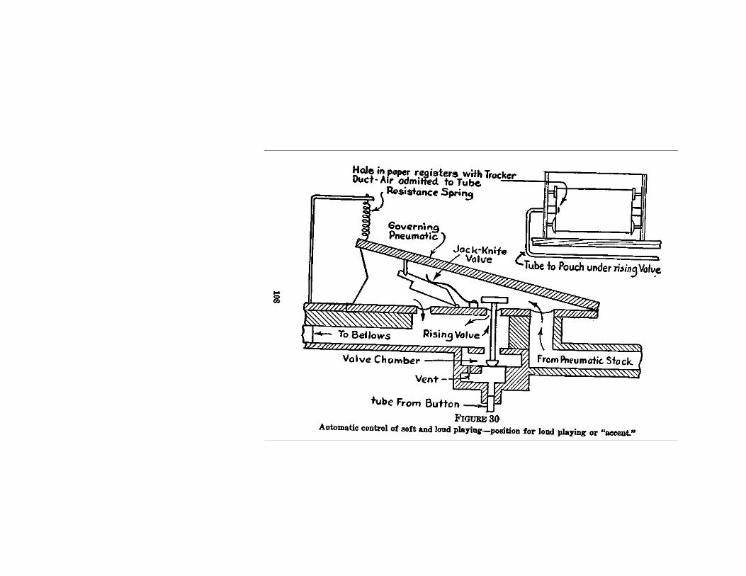
The Modern Player-Piano Described 109
under automatic control, a remarkable variety of dynamic effects in playing. Incidentally, it is well to say that the usual practice with devices of this kind is to use two of them, one operating on the bass and one on the treble half of the pneumatic stack, which is divided accordingly.
Cut-Off and Silencer. It is now only necessary to refer briefly to two more devices before going on to another branch of the subject. The reader will realize that when the re-roll lever is thrown over (See FIG. 18) it not merely opens up a large port in the tempo box but also throws a slide over the passage between pneumatic stack and bellows, thus cutting off the playing action from the bellows and silencing it during the return of the music roll to its spool. The illustration (FIG. 18) just referred to shows the simple operation of the device, concerning which it need only be added that it is sometimes supplanted by a pneumatic arrangement, which operates merely by the opening or closing of an air hole, which may be controlled through the motion of the re-roll lever. It would scarcely be necessary to refer at all to this if it were not for the fact that many player-pianos are fitted with this pneumatic cut-off, simply in order that they may enjoy also the advantage of a "silencer" when needed. To this end, the pneumatic cut-off may be con-trolled by a separate finger button on the key-bed, called a "silencer button." Whenever this is depressed the playing action is cut off and silenced.
110 Piano Playing Mechanisms
The motor, of course, drives on as usual, and thus any part of a music roll may be made to travel silently over the tracker bar. In exactly the same way the whole operation may be controlled from the tracker bar by marginal perforations.

CHAPTER III.
DIMENSIONS AND PRESSURES.
Scope of the Inquiry. This book would be incomplete if it contained no discussion of the scientific aspects of the design of player-piano actions. It is true that the course of invention and development in this field of musical industry has not been consciously conducted along scientific lines. Yet, as the problems to be solved have become steadily more complex, and the experiences accumulated during many years of trial and error have assumed greater value as guides towards correct method, there has been a strong tendency towards what may be called a "theoretical" conception of the whole subject. This does not mean an unpractical conception; it means simply a conception founded on scientific considerations, which, therefore, insists upon knowing the nature of each problem in its engineering and physical aspects, before it undertakes to solve it. The original methods worked out by player-piano manufacturers reflected the casual way in which the instrument itself arose out of experiments with automatic reed organs, and the like. These methods led to excellent results in course of
111
112 Piano Playing Mechanisms
time, but caused much unnecessary wandering along by-paths, which scientific knowledge would have avoided, and thus wasted much money, time and labor. Now, however, the player-piano industry should be put, at least to some extent, upon a level with those other industries which deal with the making of accurately functioning machines. That is to say, it is time for the player-piano industry defi-nitely to accept and establish the fundamental truth that every machine of any kind whatsoever comes within the scope of laws included within the science of physics, and of rules laid down by the science of engineering.
Engineering is merely a particular branch of the general science of physics. No man would attempt to build a bridge without knowing, or having before him, the results of knowledge as to strength of ma-terials and the facts about stresses and strains. For precisely the same reason it is certainly not legitimate today to undertake the design of player-piano mechanism without a working knowledge, accurate though not necessarily extensive, of the behavior of air at different pressures and of the engineering problems which relate to means for operating the piano action by pneumatic machinery. To the extent that the designer is acquainted with the demonstrated facts of all these matters, he is able to proceed with confidence, adapting to the mechanical limitations and engineering require-ments of the piano those immutable laws according
Dimensions and Pressures 113
to which the power source he selects for his mechanism continues steadily to behave.
In what follows no attempt shall be made to lay down a mathematical foundation for design, simply because it is not the object of this book to trace out that part of the general science of pneumatics which would be applicable to our present purpose. The object is rather to set forth for the benefit of the reader who is working in some branch of the player-piano art, those scientific aspects which he must understand, in principle at least, if he is ever thoroughly to grasp the practical development of pneumatic piano-playing mechanisms. It is not, that is to say, the purpose here to work out and express the processes of reasoning from mathematical and physical facts which would lead to fixed formulae for calculating dimensions, etc.
When figures are given they are set down in this book under the simplest possible forms, and their justification must sometimes be taken for granted. At some later time it may be proper, in the then existing state of the art, to make a complete mathematical survey of the problems of design. It will then be seen that the calculations set forth in this book have been well founded.
Nature of the Mechanical Problem. In order to grasp the nature of the process whereby the playing mechanism has been brought to its present state of development, the reader must from the start know precisely the nature of the object which that mechanism
114 Piano Playing Mechanisms
is designed to attain. In the first chapter of this book there was an attempt to explain, in general terms, the laws which govern the generation of pneumatic power, and to describe the methods whereby this power is made applicable to the action of the piano. It now remains to investigate more accurately the power requirements and the design of the mechanism intended to produce and utilize that power.
The action of the piano consists of eighty-eight identical systems of levers, pivoted upon centers so that they move in arcs. The object of the co-ordinated motions of any of the systems of levers is to secure the excitation of a group of strings, called an "unison," by means of a hammer working at the end of a pivoted lever.
The object of any piano-playing mechanism, whatever be its individual class, is to operate the eighty-eight sections of the piano action under the selective control of a perforated sheet of paper. The movement of this sheet, together with the applica-tion of the needed power to the selected sections of the piano action, constitutes the principal function of the player mechanism.
Reference to previous chapters and illustrations will serve as a reminder that the mechanical shape which the player action has taken may be con-sidered under two main aspects. The playing pneu-matics, which operate the piano action, are the most important features of the entire mechanism, and to
Dimensions and Pressures 115
their design and control much ingenuity has been devoted. In dealing with the scientific aspects of the subject, then, it is found that the first and most important subject for consideration relates to the dimensions, shape and materials for the pneumatics and their controlling apparatus.
The Principle of Opposed Pressures. The princi-ple on which the player mechanism is mechanically founded is that of opposed air pressures, or dis-turbed equilibrium. Instead of opposing bodies of air raised beyond the atmospheric pressure, to that atmosphere, the converse course has been taken of artificially reducing the pressure of enclosed bodies of air by thinning them out through suitable mech-anism and then allowing the superior atmospheric pressure to operate against these. The effective re-sult might be the same in either case, but the sub-normal system is found to be simpler and more convenient, principally because it makes so slight a demand upon the physical powers of the person who operates the bellows.
Minimum Tone-Power Requirements. The piano action of today shows an average resistance per key of 214 ounces. That is to say, any effective pressure greater than this will overcome the resistance of the action and throw the hammer. Actually, the pressure needed to obtain a sound with certainty from the movement of the hammer is somewhat greater than this. It may be said that the lowest tone-power which can be obtained from
116 Piano Playing Mechanisms
the action of the piano is produced by an effective pressure of 4 ounces. If we take any ordinary pneumatic, as adapted in the standard player mechanisms of the day, we find the superficial area of one of its walls to be usually 5, 5^ or 6 square inches. Let us take as an average 5 square inches, which, in fact, is a very nearly accurate average figure. Obviously, then, with such a superficial area, the lowest tone-power will be obtained when the effective air pressure is 0.8 ounces per square inch. Such a pressure is manifestly very low, and if no. more power than this were needed pneumatics and bellows might be very much smaller than they com-monly are.
Maximum Power Pressures. However, there is the other, or maximum, aspect of piano tone-power to be considered. A pianist hitting at the utmost of his strength probably exerts a pressure upon the key of 20 pounds, but the result is not always or necessarily effective to the extent which the figures might suggest. The art of obtaining tonal effects from the piano depends upon a variety of other considerations beyond mere strength. No discussion of these is possible in this place, but it may be said that tone effects in artistic piano playing are obtained by virtue rather of contrast and variety than of brute strength. In matters of this sort we have to deal with the question of taste, and it is safe to say that modern piano playing shuns "pounding" as such and attempts rather to
Dimensions and Pressures 117
obtain variety of color and a singing tone. The greatest musical powers of the pianoforte lie in this direction and are not brought out by any attempt to obtain tone by means of sledge-hammer blows.
With the player action which is encased in the author's own grand piano it is possible to obtain a strength of tone on single notes which is more than sufficient for all demands of playing and which compares favorably with the powers evoked by good pianists who play on its keyboard. The effective working pressure developed during very energetic playing on this instrument does not exceed 28 ounces per square inch, and this is equiva-lent to a total pressure upon the piano action of approximately 8 pounds. This seems quite satisfactory.
Normal Level of Power. If between these limits the range of ordinary piano playing is to be found, it is evident that our pneumatic system has to be considered as founded upon power requirements of not less than 1 ounce nor more than 32 ounces per square inch. If it were possible to obtain a bellows system or other sort of power plant which could deliver the lowest and the highest required powers, with equal facility and rapidity, the problems of player-piano design would be much simplified.
Measuring Pressures. In passing, it would be well to direct attention for a moment to the method usually adopted for measuring and recording the
118 Piano Playing Mechanisms
working pressure of a player mechanism. It is well known, as was set forth in the first chapter of this book, that the weight of a column of air of 1 square inch cross section and as high as the atmosphere extends, is equal to the weight of a column of water of the same section and 34 feet high. Now since the weight of such a column of air is approximately 14.75 pounds, it follows that if we place water in a tube of 1 square inch cross section, 34 feet of tube will contain 14.75 pounds of water. Therefore, 1 inch of water will weigh 0.57 ounces.
Suppose such a tube of glass is taken and bent into U-shape, leaving one end open and connecting the other by means of a flexible rubber hose to some part of the player action which we desire to test. Then let us fill the tube up with water until it is half full. Let the length of the tube be not less than 6 feet for each leg of the U. The water, which may be slightly tinted with red ink to make it more conspicuous, will be balanced by the atmo-spheric pressure and will remain evenly in the tube. If the air pressure inside the player be reduced by operating the bellows, the atmospheric pressure on top of the open end of the tube will be able to force the water downwards, around the bend and up the other leg of the U. The distance to which the water rises in the leg nearer to the player mechanism will be exactly proportional to the difference between the atmospheric and the reduced internal pressures. The more the
Dimensions and Pressures 119
internal air is thinned the more effective will the atmospheric pressure be and the further it will drive the water down the one leg and up the other. If, therefore, a scale is worked out either in inches or in ounces, according to the calculation made above, working pressure may be conveniently read from it.
Inch and Ounce Scales. In making such a scale the simplest procedure is to mark off either half-inch or half-ounce lengths on one leg only and then figure each as a whole inch or whole ounce. In other words, it is more convenient to have only one scale to read, for each inch of movement in one leg is duplicated by an equivalent in the other leg, so that the total displacement at any moment is always just twice what it would appear to be from a view of the water column in one leg only.
It might be added in this connection that custom sanctions the use of either an ounce or an inch scale for measuring working pressures. The inch system is much used but, although engineers will at once appreciate it because the scale of values it registers corresponds with their own methods, as used in compressed-air machinery, etc., it seems perhaps preferable to register the working pressures of the playing mechanism by ounces, simply because in that case we can read in terms of the work and not of an artificial register. The ounce system is therefore maintained throughout this book.
120 Piano Playing Mechanisms
Dimensions of pneumatics. Returning now to the main subject, it must be plain that the question of the size of the pneumatics which give the motion to the piano action must primarily depend upon the capacity of the power plant. If the discussion of first principles contained in Chapter I of this book is clear, the reader will understand that the bellows system of a player mechanism is in effect an appara-tus for moving quantities of air through a series of chambers into the atmosphere. This air originally comes from the atmosphere, whether through the tracker ducts or through the open-air passages of the pneumatics; it passes through the player mechanism and re-enters the atmosphere. The function of the bellows, then, is to pass the air out more rapidly than it can pass in, thus maintaining constantly inside the chambers a pressure lower than atmospheric.
Since the atmospheric pressure is equivalent to 14.75 pounds per square inch (=236 ounces) and the minimum practical playing power equals 1 ounce per square inch, it follows that so long as the bellows can maintain the internal pressure at 0.995 of the atmospheric pressure the instrument will play, though at the very minimum power requisite to produce tones from the piano's hammers and strings. On the other hand, it should not be forgotten that this statement must cover equally the cases of a single pneumatic acting to operate a single hammer and of a dozen pneumatics acting
Dimensions and Pressures 121
simultaneously. The problem of power supply, in fact, may be based upon an assumed requirement for delivering not less than 1 ounce effective pressure against the input of air from 12 tracker ducts and 12 pneumatics.
Experience shows that provision must be made to supply, as a maximum, enough power to operate not less than 12 pneumatics simultaneously at a working pressure of 32 ounces per square inch, that is to say, with an internal pressure steadily maintained at about 13/15 (say, 85 per cent.) of the atmospheric pressure. The requirements are not high, but it must be remembered that the bellows must be designed to take care of pressures up to this maximum with any number of pneumatics from one to more than a dozen, constantly and simultaneously passing air into the chambers.
Cubic Content of Pneumatics. In planning the pneumatics and chambers the first thing to consider is the best practical shape. The piano's peculiarities keep us pinned down to a very small variety of possible shapes, and practical experience shows the best pneumatics to be something like 5 inches long and 1 inch wide. If we say that the superficial area of a moving wall is 5 square inches we shall make no mistake. If we also remember that the rise of the wippen in the modern upright is 3/8 inch and that the moving wall of the pneumatic must move through this distance to perform its work, we can see that the cubic content of one
122 Piano Playing Mechanisms
pneumatic may be set down at about 2 cubic inches. Twelve of these working simultaneously at the minimum pressure (1 ounce) would require the constant transfer of 12x2xl-f-236 cubic inches = 0.1017 cubic inches of air to the atmosphere through the bellows in excess of what is entering it. On the other hand, at the maximum assumed in this chapter (32 ounces), the quantity is 12x2x32-f-236= 3.025 cubic inches more than is being poured in.
Allowance must be made for leakage (about 15 per cent.), but the actual size of the chambers need not be considered apart from the pneumatics, since the air is moving through them constantly and the process is merely one of transfer, whereby a certain quantity of air goes in at one end of what may be regarded as a single passage with two or more openings in it, and is let out at the other end.
Since the transferring capacity of the bellows is a function of the size of the exhausters (the equalizer should be disregarded for the purpose of calculation since its duty is essentially regulative), the cubic content required for the bellows may be calculated by taking the figures given above as representing one-half of the work the bellows will have to do. The other half is involved in the supply of power to the pneumatic motor.
The proper dimensions of the exhausters can now easily be calculated, since the possible length of each unit is limited by the available space between the key-bed of the piano and the floor, while the
Dimensions and Pressures 123
distance through which the exhauster can move under the control of the foot treadle is limited likewise by the convenience of the player-pianist. Generally speaking, it is not wise to allow for a moving distance greater than 4 inches.
The Valve Question A great amount of controversy has been excited at one time or another by the questions revolving around the design and the dimensions of the controlling valves, which admit the atmospheric air to the pneumatics and in turn shut off this air and permit the pneumatics to exhaust into chambers. Much, if not most, of the controversy was extremely uninteresting, simply because it was based upon erroneous premises. Today we are all agreed that any valve system which works is, de facto, correctly designed, but at the same time are ready to insist that there are degrees of effectiveness and that it is worth while considering to what extent, if any, current practice might be modified here and there with resulting advantages in economy and efficiency.
The object of the valve is to expose the pneumatic alternately to the inflow and outflow of atmospheric air. In the one case the atmospheric air is caused to flow out from the pneumatic when the latter is put in communication with a chamber from which some of the normal content of air has been withdrawn by the operations of the bellows. In the other case, the passage between pneumatic and chamber is closed and the atmosphere again
124 Piano Playing Mechanisms
admitted to the pneumatic, which has been partially exhausted and which now immediately fills. The reader is aware that these two processes result in the alternate closing and opening of the pneumatic. The pneumatic closes when and because the atmospheric pressure forces inward the moving wall against the lowered internal pressure. It opens again when and because the inrush of atmospheric air balances the internal and external pressures, so that the combined powers of the small hinge-spring in the pneumatic and of the weight of the piano action become sufficient to force the pneumatic open.
Plainly, therefore, the valves which are to control this alternate process must obey the following requirements :
1. They must be as light as possible, because their action must depend upon the low power afforded by the effective working pressure.
2. They must always seat themselves positively and hermetically.
3. They must open up passages large enough to promote prompt flushing and re-filling of the pneu-matics.
4. They must, in fact, be thoroughly depend able through a range of circumstances wide and varied.
Reasons for Different Systems. There are two systems or methods employed by the designers of player actions to secure the requirements here set

Dimensions and Pressures 125
forth. In the earliest days the control was vested in a single valve of the very simple kind shown in FIG. 10. Somewhat later, for reasons which have been already described (Chapter II), it was found decidedly advisable to interpolate between the original valve and the tracker bar a sort of relay valve. The air entering the tracker duct raises the relay (primary) valve which, in turn, uncovers an air port leading air under the original (secondary) valve. The first valve can, of course, uncover a larger air port than can be furnished by the tracker duct, owing to the strict limits placed upon the latter by the standards adopted for perforating music rolls. Consequently, the double system is useful whenever the amount of air which can be brought through the tracker duct, when the pressure difference between atmosphere and internal air is not great, does not seem sufficient to move the single valve rapidly and with certainty.
Reference to the discussion in Chapter II will show why, if a player action is at all leaky or able to develop only small differences between inside and outside pressures, there is always an antecedent probability against the single system and in favor of the double.
On the other hand, it is equally easy to see that the gravamen of the whole problem is in the question of the weight of the controlling valve. If that valve can be made light enough to be under the sure control of the tracker-duct air, and simultaneously
126 Piano Playing Mechanisms
large enough to uncover an aperture into the pneumatic which will flush it properly, then there is no need for the relay valve with its additional chest exposing a large additional volume of air to he maintained at reduced pressure, and so throwing additional burdens upon the bellows or other exhausting plant. The question again depends upon the dimensions of the pneumatic which, as has been pointed out earlier in this chapter, are functions of the working pressure. That is to say, a player able to develop high working pressure, airtight and well constructed according to the best engineering practice, may be much better built on the single-valve system. On the other hand, if there is plenty of power to spare (as where the exhausting is done electrically) it may be advisable to purchase complete assurance at the price of additional equipment.
Valve Dimensions Calculated. What was said in a previous part of this chapter about the dimensions of the pneumatics may now be applied to considering the dimensions of the valves in both valve systems. The single system, it must be repeated, depends upon the lifting power of the very small quantity of air which can be introduced through the tracker bar. If the cubic content of the average pneumatic be taken as 2 cubic inches, then we have to consider the possible need to transfer as often as 10 times per second not less than .1017 cubic inch of air through an orifice controlled by the
Dimensions and Pressures 127
valve. If the aperture be circular and of 1-inch diameter, its area will be about 0.8 square inches. If it rises at each operation to the extent of .03 inches, the required minimum transference can take place easily enough within the assumed time limit. Transference of larger quantities will not require a higher rise of the valve, because the rapidity of movement through the orifice is a function of the excess of outside over inside pressure. In other words, the harder we pump the more rapidly, other things being equal, can we transfer air from pneumatic to bellows.
It must be assumed that in the case of the minimum working pressure (1 ounce effective per square inch) the speed of movement from one region of pressure to another is just equivalent to a movement of .03 of linear transmission in 0.1 second. This assumption, however, is not unpractical.
In fact, the difficulty under which one labors in dealing with a variable whose movements cannot be predicted with any certainty, is a difficulty only in respect of devising exact figures. In practical con-struction the very condition which is abstractly so unfortunate works to allow a margin for error. If it were not for this margin one could hardly imagine where the player-action would be.
Lastly, from the figures suggested above it may be seen that at a minimum pressure of 1 ounce and a tracker duct area of, say, .0035 square inch, a pouch of 1.25-inch diameter (=1.22 square inches
128 Piano Playing Mechanisms
in area) will have a lifting power equal to the ef-fective weight of the air column divided by the area of the pouch. In the case assumed, supposing the average length of a tracker tube to be 36 inches, we should have at the minimum pressure a lifting power equal to 36X.0035-T-1.2=.105 ounces, approx-imately. This seems too small, considering that an ordinary valve in a single system will weigh more than this, usually about .25-ounce. But in practice the working pressure is always much higher, so that given airtightness of construction, the requirements are met by the dimensions set forth for the case of a single-valve system. Moreover, the case can be bettered still further by the adoption of higher pressures with consequently smaller areas to be affected.
These calculations are naturally provisional and are presented only as a basis for calculation. In all these cases everything depends upon construction, that is to say, upon the working pressure normally attained and upon the comparative airtightness. The facts adduced mainly show how closely the suc-cessful makers have approached to abstract prac-tical perfection.
CHAPTER IV.
AUTOMATIC POWER AND AUTOMATIC EXPRESSION.
By the term "automatic power," reference is made to pneumatic power produced by some mechanical substitute for the feet of the player-pianist. Among the very earliest pneumatic musical instruments were the ancestors of the present very well known coin-operated player-pianos, which for years have been powerful factors in the music industries by reason of the wide appeal they make to all places of public resort and entertainment. In these instruments, early as well as late models, the system includes three separate elements: (1) an electric motor-driven power plant; (2) a pneumatic stack; (3) a series of automatic devices for doing what otherwise would be done by the human operator in relation to expression, stopping and starting; and (4) a coin-operated control, whereby a nickel or other coin dropped in a slot starts the music going, and continues it until it is brought to a close by some form of control apparatus preferably set in motion through the agency of the music roll itself. The whole great group of coin-operated player instruments
129
130 Piano Playing Mechanisms
may be roughly classified after this fashion. The reader will doubtless be more or less familiar
with these facts concerning the coin-operated in-strument, and so will follow without difficulty, when it is said that by analyzing the first and third of the elements mentioned above, a general understanding of the principles which underly the whole recent development of automatic expression player-pianos and reproducing pianos can be gained. The present chapter constitutes an indispensable preliminary to the more elaborate detailed studies of these instruments, which are to follow.
The Automatic Power Plant. The power-plant question may be discussed in short order. A set of two or three pumps* may be arranged around a shaft rotated by an electric motor of about 1/8 or 1/10 horsepower, which revolves usually at about 1,200 revolutions per minute, and is geared so that the pumper shaft turns at something like 1/10 of that speed, the actual figures depending upon the dimensions of the pumps. The smaller these are the faster they must rotate. On the other hand, the faster they rotate the more noise is likely to be developed, and noise, of course, is to be avoided if possible.
The practice of most manufacturers favors the slow-speed pumps with equalizer and accessories
♦In dealing with motor-driven exhaust plants, the word "pump" is commonly applied instead of "exhauster."
Automatic Power and Automatic Expression 131
of ordinary type, very much the same as in the foot-operated system. But some have adopted the highspeed, enclosed fan, rotated by a high-speed, direct-connected motor, the whole put up in a small and convenient dust-proof case. This latter, as made by the Motor Player Corp., for instance, is no larger than a big kettle and can be attached at the side of an ordinary foot-operated bellows-system in any waste space beneath the key-bed of an upright or under the framing of a grand player-piano.
The pneumatic aspects of these power plants present no new facts, and the reader has merely to remember that whether reciprocating bellows or rotary fan be concerned the function of the apparatus is to cause air to move from the interior of the player action continuously outwards to the atmosphere. Furthermore, in regard to the electrical facts there is very little to be said in this place. Electric motors today are almost, if not quite, foolproof, and unless they and their wirings become water-soaked there is little ever likely to go wrong with them. Some special points connected with the coin-operated instrument's electrical features will, however, be considered in their proper place.
We turn then without further ado to the question of automatic expression. Like many other matters this has sometimes been clothed in much mystery. Analysis, however, shows how comparatively simple the whole thing is.
Mechanical Elements of Musical Expression.
132 Piano Playing Mechanisms
From the physical standpoint, musical expression can be reduced invariably to the following elements :
1. Selection of the tones to be evoked. 2. Time-relations in and among single tones and
groups. 3. Comparative loudness or softness of each
tone, as depending upon tactual control at the keys. 4. Comparative loudness or softness as con-
trolled by accessory devices, such as soft pedal. 5. Sostenuto, color and other subsidiary ele-
ments, as controlled or determined by the use of other accessory devices, such as damper pedal.
A musician would not unnaturally object to this classification as incomplete. But if it is to be always assumed that the ultimate directing authority behind all the mechanical arrangements is the musician, the objection will not hold. The ultimate directing mind is present in person when the interpretation of music is made by the player-pianist controlling the pneumatic power at each moment, through his conscious volition. It is equally present in all cases of automatic expression, but is then removed one step backwards, since the interpretation has then been caught, fixed and reduced to a permanent set of interlocking mechanical functions, directly controlled by the music roll, which comprises the intermediary link between musician and mechanism.
Non-dynamic Elements of Phrasing. In the
Automatic Power and Automatic Expression 133
above list of mechanical factors the first and second present no unfamiliar difficulty. That is to say, we are all aware that it is possible to take off, from the actual piano playing of a musician, a record which can be reduced to a perforated music roll, whereby each tone evoked at the keyboard is recorded both as to its identity and its duration. Thus the elements of phrasing are preserved so far as concerns the non-dynamic features thereof. These latter have to be furnished in another way, as we shall see.
The so-called hand-played roll, so familiar during recent years, is a record thus made of the selection and grouping, as to duration and phrase-pattern, of the tones evoked by a pianist in playing some musical composition.
Mediate Solution of Dynamic Problem. If it is desired to go further and record in some way the dynamic stresses, accents and emphasis placed by the musician during his playing, thus to complete the record of his phrasing, the problem becomes extremely complicated. But the matter of recording "touch" has been worked out with satisfactory results by a process of making a sort of index of the dynamic effects. The changes in the pianist's stresses, accents or emphasis, as well as the more gradual changes in the level of his general dynamic scheme, are through this indexing process indicated upon the master roll by means of perforations through which are operated the dynamic devices. In the hands of those who are best skilled in this indexing
134 Piano Playing Mechanisms
process, the results obtained are in every sense sat-isfying.
Recording Pedal Work. The elements of expres-sion classified above under the fourth and fifth head-ings are easily recorded directly, since they involve only simple mechanical motions by the pianist's feet, similar to the contact motions of the fingers on the keys. There is, therefore, no difficulty in obtain-ing a direct record of the number of times the pian-ist depresses and releases each pedal, and of the position of each such operations relative to the rest of the interpretation. Such a record may be by a pencil trace on a moving sheet, or otherwise.
Ultimate Analysis of Dynamic. Assuming, then, that there is a graphic scheme of some rough sort which may be used as an indication, it remains to reduce this to practical mechanical control. It is obvious that the whole matter may be brought down ultimately to groups of variations in the working pressure of the player mechanism. In other words, since loudness is a function of key motion, and hammer velocity a function of that, it follows that hammer velocity, which determines loudness, is a function of pneumatic velocity when the player mechanism is used. The velocity of closing of a pneu-matic is a function of the working pressure. Change the pressure, then, and we change the loudness value of the tone or tones evoked. If, then, we can arrange to make a sufficient number of these changes, through a sufficient variety of degrees, it
Automatic Power and Automatic Expression 135
follows that we can obtain any number of different loudness values and, so that, if these can be controlled, it becomes possible to supply pneumatic equivalents for every kind of key-pressure which the pianist uses for the purpose of establishing such loudness values as he desires.
We are perforce obliged to separate the different elements of expression in a way in which they are never separated by the pianist. The classification adopted here, in fact, is necessary for the analysis of the method of attaining to automatic control of expression. When all the processes are joined together and set going simultaneously they fit into each other without the least difficulty.
Returning then to our mechanical translation of touch values, we see that the problem is to obtain equivalent working pressures, alterable at will. It was already shown in Chapter II that the system then described for making changes of pressure under control of the player-pianist can easily be arranged to be worked automatically through the music roll. (See FIGS. 29 and 30.)
Simple Solution of Dynamic Problem. Now let it be plainly understood that, upon some modification or adaptation of the simple principle shown in FIG. 27, the whole practice of automatic expression, even in the most refined reproducing pianos, is clearly based. When this fact has been properly grasped, design of any reproducing mechanism can readily be grasped also.
136 Piano Playing Mechanisms
For it must be evident that if the single pneumatic (FIGS. 29 and 30) be replaced by, say, three or four, each affecting the size of the air passage, so as to form a series of power (pressure) steps or gradations, and if corresponding perforations are arranged on the tracker bar, then it becomes mainly a matter of scheming the succession of the different controlling perforations from the indications supplied as above described, or in any other suitable manner. Assuming that, as of course always happens, the general relative loudness value of the tone-power evoked by each of these pre-determined mechanical operations is known, an adequate approxi-mation may be obtained to the dynamic scheme originally registered upon the keyboard by the pianist.
It is clear, I suppose, that I am not attempting to describe by this crude picture any specific method as now utilized in making reproductions of pianist's touch. The object of the present discussion is to get the reader to grasp the principles involved. Later on we can consider the many refinements and developments of the original principle.
This, however, is the principle, and as such should be carefully studied until it is completely understood.
In order to make the argument still clearer another illustration is appended which shows a somewhat different arrangement, where a series of four pneumatics, arranged upon a lever, can exert
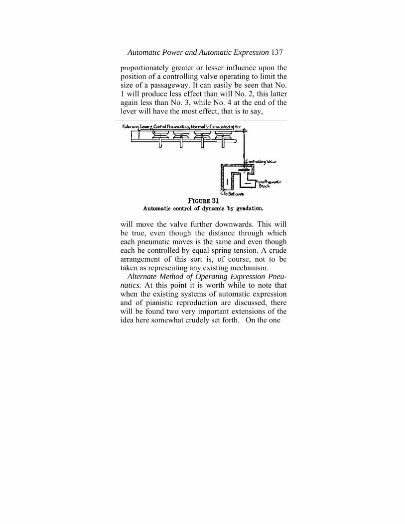
Automatic Power and Automatic Expression 137
proportionately greater or lesser influence upon the position of a controlling valve operating to limit the size of a passageway. It can easily be seen that No. 1 will produce less effect than will No. 2, this latter again less than No. 3, while No. 4 at the end of the lever will have the most effect, that is to say,
will move the valve further downwards. This will be true, even though the distance through which each pneumatic moves is the same and even though each be controlled by equal spring tension. A crude arrangement of this sort is, of course, not to be taken as representing any existing mechanism.
Alternate Method of Operating Expression Pneu-natics. At this point it is worth while to note that when the existing systems of automatic expression and of pianistic reproduction are discussed, there will be found two very important extensions of the idea here somewhat crudely set forth. On the one
138 Piano Playing Mechanisms
hand, since the adoption of electric pumping plants in player-pianos of this type, whereby a steady level of working pressure may be maintained in all circumstances, it is possible to maintain normally, in a state of partial vacuum, any of the pneumatics which are used for expression control. There are various advantages in thus reversing the more usual state of affairs, especially in respect of rapidity of operation and delicacy of control, but nothing of the sort could be efficiently undertaken if there were no system of uninterrupted power supply. It will be well to keep this fact in mind so as to avoid con-, fusion when we come to consider some of the existing reproducing piano systems.
Smooth Crescendo and Diminuendo. The second extension of the principles laid down is found in the fact that something more is needed than a set of gradations, or steps of loudness, to obtain a good reproduction of a pianist's playing. To retrace for a moment some of the ground already covered, let us remember that we have already seen how the management of a series of power steps becomes the central problem of reproducing pianistic interpretations. If now we can dispose of two sets of these governing arrangements, one operating on each half of the action, we can combine them pretty skillfully and can obtain very natural effects of accent and stress, especially if the apparatus works fast enough, and so allows very rapid changes from high to low power and back again by any of the
Automatic Power and Automatic Expression 139
intermediate steps. I mean that if the apparatus operates with sufficient rapidity, step No. 1, or No. 4, or No. 3, or No. 1 again, No. 2, and so on, will succeed each other rapidly enough to give a wide variety of effects. It is necessary to decide what steps, that is, what pressure, will at any point correspond to representing the loudness value given by the pianist at that point. The paper at that point is then perforated to register with the tracker duct which controls the corresponding power. Given a player action divided into two halves, so that combinations of power can be arranged, with each half operating independently its own set of expression pneumatics and valves by means of its own tracker ducts, and it is plain that a vast number of possible power combinations can be organized.
Pianistic Effect of Crescendo. Yet it is found that something more is needed. Anyone who is familiar with piano playing knows that a good pianist can begin to play at a certain level of sound-power and then gradually work up, by what is known as "crescendo," in such a way that he attains the utmost of his powers without his hearers becoming conscious of the steps or gradations through which he has passed. Yet, since the pianist does this by means of his muscular control, he does, in fact, proceed by steps; but he has the ability to shade these into each other more completely than can be exactly reproduced by any simple system of mechanical power steps. It is necessary, therefore,
140 Piano Playing Mechanisms
to provide some mechanism for reproducing this gradual increase in power to a maximum, or its gradual decrease to a minimum, without allowing the power-steps to stand out awkwardly. We want, so far as possible, to have the artist's sound-effects proceed, in such a case, so smoothly that the effect is of a steady unbroken ascent.
Outline of a Crescendo Method. Returning to what was set forth in connection with FIG. 31, that diagram is now reproduced with two differences. On the one hand are shown the power-step pneumatics placed under the lever, and not above it, as before.
•On the other hand is shown a valve box with a simple valve system connected with the control per-forations of the tracker bar. One side only of the total outfit is shown, be it remembered, for from now onward there will have to be considered any control device for dynamic expression as operating on either the bass or the treble half of the piano, with a precisely similar device operating on the other half. Of course, this is no representation of any existing system, though the present illustrations are based for reasons of convenience on a system which will be fully described in the proper place.
The reader will now observe that the control pneumatics are, in turn, under the control of a master pneumatic which, unlike them, is kept norm-ally under atmospheric pressure. This master pneu-matic has a set of two valves and a vacuum chest
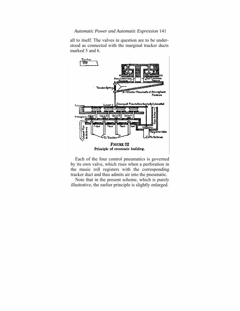
Automatic Power and Automatic Expression 141
all to itself. The valves in question are to be under-stood as connected with the marginal tracker ducts marked 5 and 6.
Each of the four control pneumatics is governed
by its own valve, which rises when a perforation in the music roll registers with the corresponding tracker duct and thus admits air into the pneumatic.
Note that in the present scheme, which is purely illustrative, the earlier principle is slightly enlarged.
142 Piano Playing Mechanisms
Upon the other side of the lever, to which is attached the big regulating disk in the main air passage, is what is termed a "master" pneumatic. This is supposed to be under atmospheric pressure and so to be expanded. Its moving wall is connected with a tension spring, as well as with the lever, so that when it remains expanded the position of the lever is balanced with respect to the influences exerted upon it by the pneumatics on either side of it. The four small pneumatics on the underside of the lever are kept in partial vacuum, and it is assumed that the combined weight of these equals the weight ,of the master pneumatic, as this is expanded and spring-loaded.
Let us suppose also that, while matters are in this condition, the regulating disk is set at the position where the playing power will be at the lowest practicable point. Then, obviously, if the whole system be at rest, as when the tracker bar perfora-tions illustrated in the diagram are sealed by the music roll entirely, the playing will be at the lowest point of power, or, as we say in music, at ppp.
Let us now suppose that this condition of rest is disturbed. A marginal perforation in the music roll registers with the hole in the tracker, which communicates with small pneumatic No. 1. This at once expands, for the action of admitting air under its valve raises that valve and admits atmosphere to the pneumatic, as will be seen from the diagram. This causes the lever and regulating valve to rise a
Automatic Potoer and Automatic Expression 143
little way, which enlarges the air passage so that the playing power is increased in that proportion. Similarly, if any of the other pneumatics, or any group or combination of them, be caused to expand, the lever will be thrown up, more or less, and the size of the passageway through which the air flows between the pneumatic stack and bellows will be correspondingly altered. It is obvious that by grouping the arrangement of the marginal perfora-tions in the tracker bar so as to cause the pneuma-tics to rise in groups of two, three, or even four, sharp accents can be made and many delicate changes from one power to another.
Fast and Slow Crescendo. This, however, would not be sufficient for the purposes of artistic playing. It is often necessary to obtain a smoother and quite slow general increase of sound, without disturbance of accenting power but by raising the sound level on which the playing is built. This is what musi-cians call building up a crescendo, and is a feature of the playing of true artists. Since the four small pneumatics, whether used singly or in groups, are very useful for accentuation, it is plain that, if we hold the lever securely in any position whatever, the small pneumatics will continue, in all cases, to do their little duties of lifting the lever slightly, more or less, as they are called on to function. In other words, we can choose any fixed position we like for the lever, and alter this from time to time as we choose. The four small pneumatics will always
144 Piano Playing Mechanisms
break the fixed level, more or less, for such time as they are in operation. If we examine the master pneumatic, which is
placed in the diagram, we shall see that it has two valves, corresponding with tracker ducts Nos. 5 and 6. The first opens up a large exhaust passageway, and the other a small one, as can readily be perceived. Should No. 5 therefore be made to operate, the master pneumatic will collapse rapidly and lift the lever with corresponding swiftness. On the other hand, if No. 6 is caused to operate, the master pneumatic will collapse slowly and lift the lever gradually. By using either of these as desired it ' would be possible, therefore, to obtain either a rapid or a slow crescendo without losing the power to create rapid accents.
It will be equally obvious that some sort of can-celing or cutting-out arrangement will have to be used in any such action as described, in order to control the functions of the master pneumatic. The duration of a crescendo might indeed be determined by the length of the marginal perforation corre-sponding. But this would involve a nasty problem in music roll manufacturing, as the roll does not work well with very long perforations. A better way would be to lock the operating valve in position as it rose and then have another valve to break the lock when the crescendo came to an end. Arrangements of the sort are actually in use.
Basic Principle Always the Same. Of course,
Automatic Power and Automatic Expression 145
the system suggested is by no means the only one possible, nor does it in any way depart from the principle which governs all mechanisms of the kind. This principle is the principle of varying pressures and depends mechanically upon the size of a passageway through which air flows from stack to bellows. Any and every automatic expression instrument must embody some method or scheme for obtaining momentary alterations in the size of a controlling passageway, and the reader can easily see that with a little imagination a good many possible methods can be envisaged. For instance, the automatic expression governor, described in Chapter II, FIGS. 25 and 26, could easily be expanded to cover any required number of steps of power. And it is possible to imagine almost numberless variations in the general embodiment of the principle. Some of the possible variations may be noted for purposes of comparison. It has been chosen, for the general argument of this chapter, to trace out the development of an idea which, in its fullest and most elaborate embodiment, finds place in the reproducing mechanism known as the Ampico, which, among others, is described in the next chapter. On the other hand, in that other famous mechanism known as the Duo-Art, the regulation of the air flow is done by means of a jack-knife valve, the position of which is operated by a master regulating pneumatic and also by a set of accentuation pneumatics, each of which can close only to a certain distance
146 Piano Playing Mechanisms
and so can effect the position of the jack-knife valve only to a corresponding extent. Again, in the well-known Welte Mignon the main airflow passes through a governing pneumatic which is fitted with a jack-knife valve. The position of this valve is gov-erned by the rapid or slow closing of the second pneumatic, which, in turn, may be sharply limited in its travel by a third pneumatic, introduced for the purpose of limiting the upward travel of the second pneumatic.
There is also a class of mechanisms in which va-riations in the rapidity of air flow from pneumatic stack to bellows are obtained by introducing atmo-spheric intakes of different sizes, or by what is some-times called "bleeding in" outside air, whereby the partial vacuum is rendered more or less powerful, as required, in a series of steps.
CHAPTER V.
THE REPRODUCING PIANO.
It is not proposed in this chapter to attempt the Herculean task of giving an absolutely exhaustive account in every detail of the mechanism of every known make of reproducing piano. Not only would such treatment expand this book to impossible dimensions, but it would at the same time involve the hapless author in the unending task of revising and keeping up to date huge masses of collected material. Instruments of this kind are being constantly improved, and it is impossible in any text book to keep up with all their changes in detail. However, what can be done, and what is done here, in fact, is to acquaint the reader with the broad general principles of the leading mechanisms and give him such an understanding of them that he will be able to find his way through any of them by sheer funda-mental knowledge, in case he does not have at his disposal one of the "repairman's booklets," which all the makers of reproducing pianos distribute gratis.
Incidentally, it should be pointed out that every person who makes the slightest pretense to doing competent technical work on player-pianos should
147
148 Piano Playing Mechanisms
endow himself with all the technical literature of the kind mentioned above. The great manufacturing houses are only too happy to put into the hands of every man who shows an intelligent mechanical interest in their player and reproducing mechanisms, detailed descriptions and instructions for testing and for repair.
Testing, of course, forms one of the principal elements in the service work which all manufacturers of reproducing pianos are called upon to render. One of the objects of the present book is to make as many men as possible acquainted with the general idea of the reproducing piano, and with its leading applications, in order that each may do his share in his community in taking up this vastly important and hitherto neglected work. For reasons into which it would be unprofitable to go, tuners and technical men generally have not always worked together harmoniously with the promoters of the reproducing piano. It is probably a case where both parties are partially at fault; but that, of course, does not help matters. What is important is to spread as widely as possible all the generalized knowledge that can be compressed into a reasonable number of pages. Such is the object of this book.
Details not treated here, such as the minor points of test work, in which the working of each accessory device is measured and, if necessary, corrected according to a set of more or less arbitrary rules
Reproducing Piano 149
furnished by the manufacturer and predicated upon the instrument's general playing capacities, will be found in the special technical booklets issued by these manufacturers.
Preliminary Attitude to be Adopted. As already stated, the reproducing piano must be understood exactly for what it is if any competent technical work is to be done on it, or if even the intentions of the makers in the constructions they have adopted are to be properly and sympathetically comprehended. These intentions are partly musical, and partly mechanical. They have from the first been dominated by the necessity for conforming musical requirements to mechanical possibilities, and one who thinks too much about the latter of these two elements will perhaps find it difficult, till he is con-vinced by actual hearing, to believe that the solutions arrived at by such simple means could, in reality, be as fine as, by public and professional opinion, they are proclaimed to be.
It will now be our business to find out (1) what the mechanisms attempt exactly to do, and (2) what mechanical means they use to these ends.
Ultimate Principle of Expression Control. From the previous discussions it is clear that all expression depends upon the attainment of adequate control over rapidity of air flow. It is further clear that this main objective must be supplemented by others, including control over the speed of roll travel, as well as control over the loud and soft
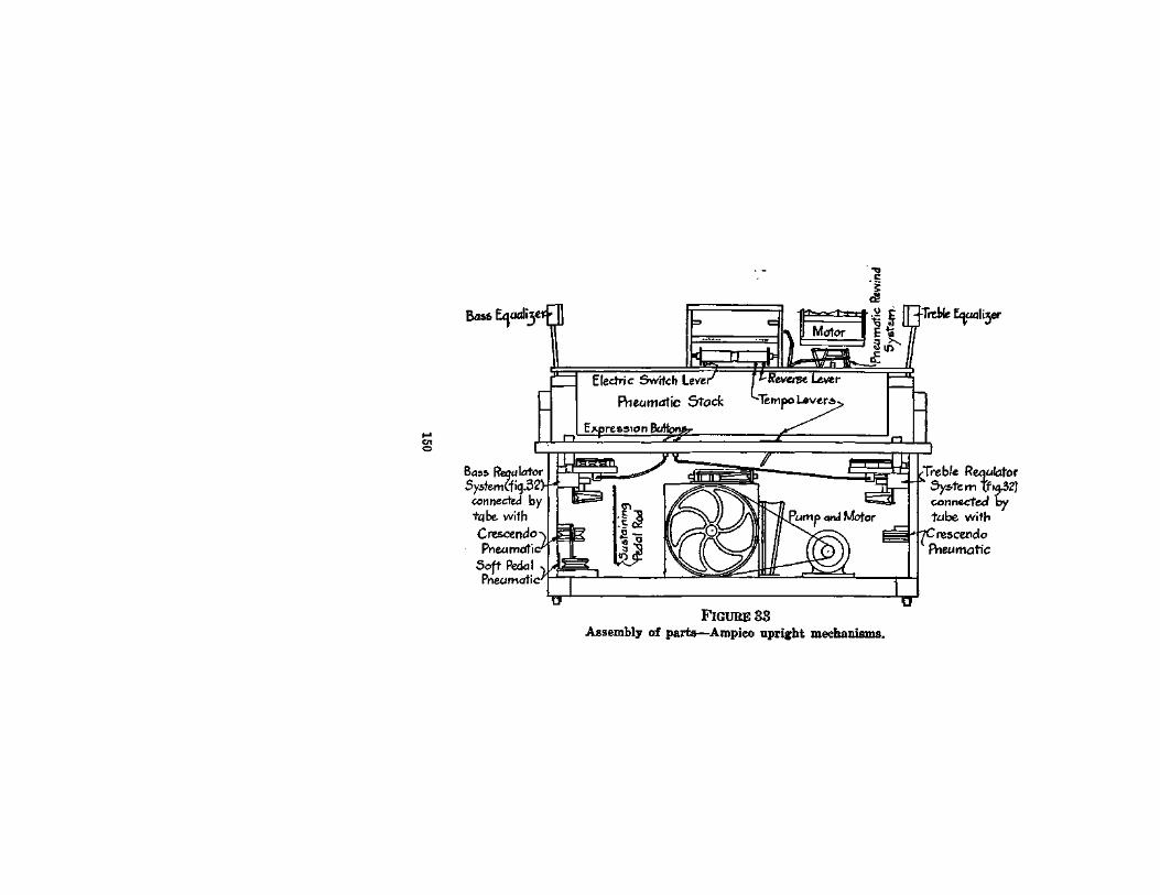
Reproducing Piano 151
pedal devices of the piano, and over such purely accessory devices as have to do with electric current, starting and stopping, etc. It will be convenient first to discuss some of the leading embodiments of the idea of controlling the rapidity of air flow from pneumatic stack into bellows, which constitutes the ultimate mechanical principle of the reproducing piano.
THE AMPICO SYSTEM. (AMERICAN PIANO COMPANY)
The discussion in the previous chapter will have made the reader acquainted with what is the leading idea in the Ampico system, viz.: the balancing of a regulating valve between two sets of pneumatics. The detailed working out of the device is very much more elaborate and mechanically perfect than the crude diagrams I used there to show the principle. In order to understand the general arrangements of the Ampico it will be best first to look at FIG. 33, herewith appended, which shows the outlines of the assembly of the Ampico mechanism.
Passing over parts which are common to all player actions, we note (1) the electric driven pump system,, which takes the place of the ordinary bellows and pedals; (2) the expression system and crescendo pneumatic, in two sets, one for each half of the player action, installed below the key-bed on each side of the piano. The other details will in most cases readily be recognized upon examination
152 Piano Playing Mechanisms
of an actual instrument, and most of them will be explained incidentally in the course of the remarks which follow.
The expression system of the Ampico depends, as I have said before, upon a method of maintaining or disturbing the balance between two sets of op-posing forces, represented by pneumatics under vacuum. By maintaining the balance, or disturbing it, as the case may be, the position of a valve is changed, as it stands in a passageway, and in consequence the quantity of air flow possible from moment to moment is correspondingly altered.
All musical expression in the player-piano, as repeatedly explained, depends upon some such con-trol of the size of an air passage. All ordinary play-er-pianos and all reproducing pianos, too, operate fundamentally upon this principle.
Expression System Described. The Ampico ex-pression system is shown in greater detail in FIG. 34. It consists of a regulator valve, which is held in balance between a large pneumatic below it and three small ones above it, being connected mechani-cally to both through a rod and a fulcrumed lever. Below the set is the crescendo pneumatic, which is pneumatically connected with the up-push or under-side pneumatic in the set by means of a suction tube running from one to the other. Normally, then, the air pressure in both these is always the same, since air flows freely from one to the other.
It will be seen that if all the pneumatics in the
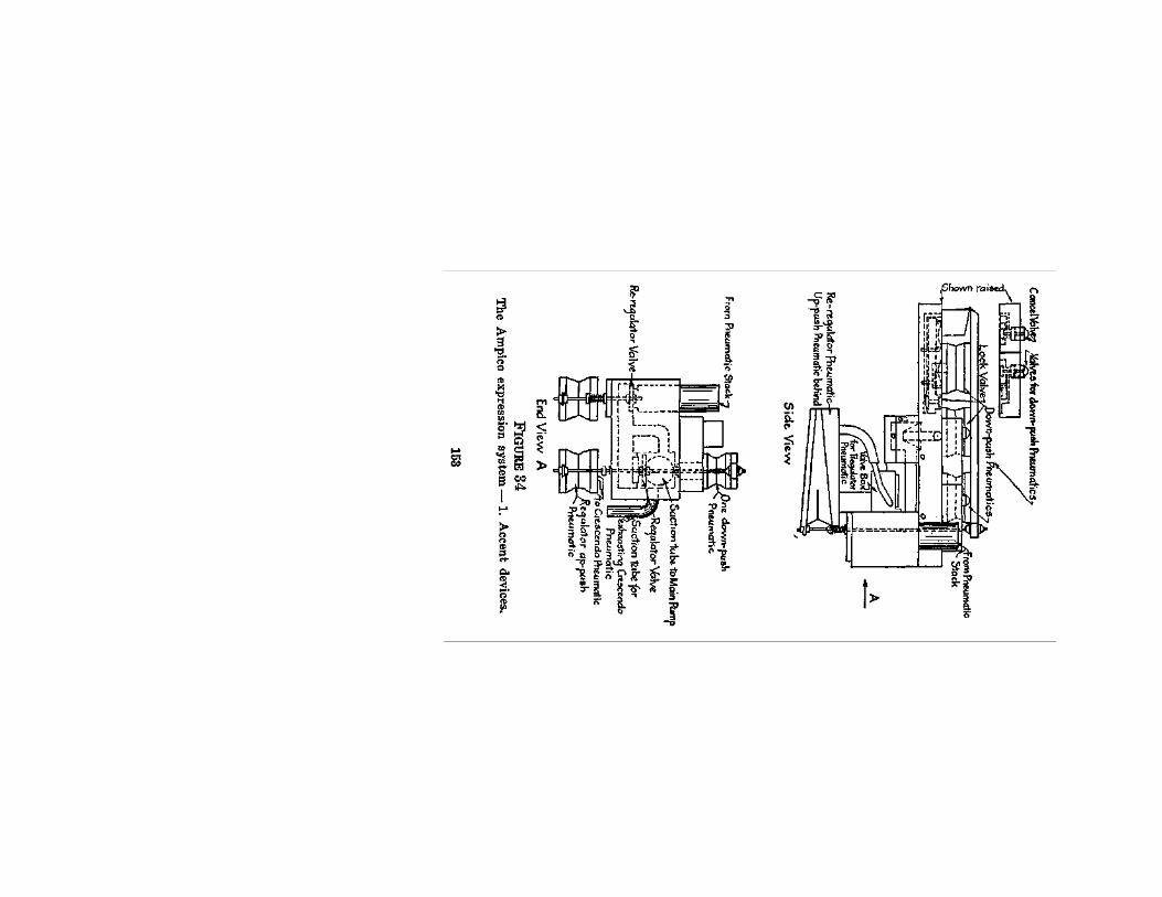
154 Piano Playing Mechanisms
expression system are kept normally in partial vacuum the regulator valve will be in a state of rest. This is the normal condition of affairs. The three upper-side pneumatics tend to push downwards on the disk, and the larger under-side pneumatic tends to push upward. For precisely the same reason the crescendo pneumatic (See FIG. 35), which is connected with the up-push pneumatic (called, in the Ampico terminology, the spring pneumatic), also tends to maintain the balance of the regulator-valve.
The illustration (FIG. 34) shows that there is a valve box attached to the system. This contains five valves. Three of these connect with the three small down-push pneumatics (called in Ampico terminology, intensity pneumatics), while one is a lock valve and one is a canceling valve.
How Expression System, Works. Suppose the system at rest. The intensity valves are all on their seats. If atmosphere is admitted through a marginal tracker bar perforation to one of the intensity pneumatic valves, this rises and distributes atmospheric air by two small tubes, one leading to the corresponding intensity pneumatic and one to the lock valve. The intensity pneumatic fills with air, expands and lifts on the fulcrumed lever, dis-turbing the balance of the system, raising the regulator valve and increasing the size of the air passage from pneumatic stack to pump system. The relative extent of the increase in air passage dimensions
Reproducing Piano 155
will depend upon the leverage exerted by the pneumatic on the fulcrumed lever, which in turn will depend upon its position along the lever. Each intensity pneumatic, therefore, will have a different effect. In this manner, as can at once be seen, if the spring pneumatic remains at rest the position of the lever can be altered at will by the action of one one of the intensity pneumatics, whereby as many degrees of accentuation may be obtained. The range of accenting power, of course, is vastly increased by additional control which can be exerted over the spring (up-push) pneumatic and its accompanying crescendo pneumatic on the other side of the fulcrumed lever. This will be treated later.
Lock and Cancel Valves. Meanwhile, let us return to the intensity valve which was left risen above, its seat. It was stated that atmosphere entering under its risen disk is disturbed in two directions. One has been described. The other is through another tube and over (not under) the so-called lock valve. The lock valve is thus held down by atmospheric pressure on top of it, and in this position it shuts off the vents which otherwise would act on the pouches of the intensity valve. So long as these are shut off the pouches will stay up, because the air in the marginal tracker tubes will not be sucked out into the vacuum chamber of the expression system. Thus, even though the control-ing marginal perforation has passed over, the intensity valve will remain up and the intensity

156 Piano Playing Mechanisms
pneumatic will remain expanded and operating, so long as the lock valve stays down, which, in turn, is in-definitely, or until something else happens. As a matter of fact, something else does happen, as we shall now see.
For since it is necessary from time to time to put a stop to the action of the intensity pneumatic and to cause it to collapse again, a marginal duct in the tracker is provided, with which, at appropriate times, marginal perforations in the music roll register. Thus, atmosphere is admitted under the cancel valve, which is shown in the drawing to the left of the system. This valve rises and admits atmosphere which flows along a tube under the pouch of the lock valve. The latter is thrown upwards, freeing the vent and causing the intensity valve pouch to fall. Thus, the latter valve is brought to rest and the corresponding intensity pneumatic collapses.
One lock valve and one cancel valve suffice to control the three intensity valves.
Let us now turn to the pneumatics which are placed in the under side of the system.
The Crescendo System. The spring, or up-push, pneumatic is exhausted from the crescendo pneumatic by means of a suction tube passing from its upper wall and into the crescendo pneumatic below it. From the latter passes a larger suction tube which runs into the regulator valve chamber's main air-flow passageway for exhausting purposes.
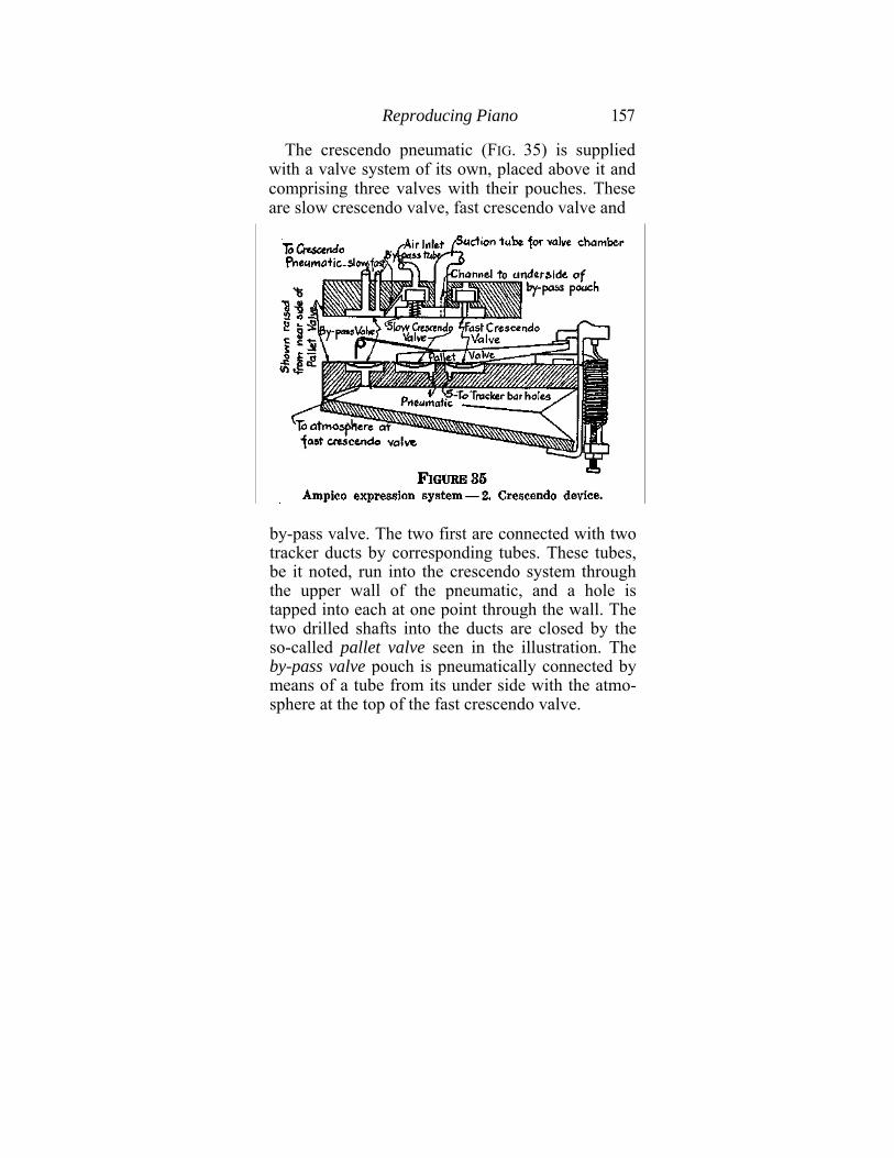
Reproducing Piano 157
The crescendo pneumatic (FIG. 35) is supplied with a valve system of its own, placed above it and comprising three valves with their pouches. These are slow crescendo valve, fast crescendo valve and
by-pass valve. The two first are connected with two tracker ducts by corresponding tubes. These tubes, be it noted, run into the crescendo system through the upper wall of the pneumatic, and a hole is tapped into each at one point through the wall. The two drilled shafts into the ducts are closed by the so-called pallet valve seen in the illustration. The by-pass valve pouch is pneumatically connected by means of a tube from its under side with the atmo-sphere at the top of the fast crescendo valve.
158 Piano Playing Mechanisms
When the system is at rest the two crescendo valves are seated down on their pouches. The bypass pouch, however, is expanded through atmospheric pressure coming from the top of the fast crescendo valve, and so is seated against, and holds shut, the fast crescendo or wider one of the two passageways which run through the top of the system and then, by means of rubber tubing on the outside of the crescendo pneumatic, into the inside thereof. This position of the by-pass valve would thus prevent any effect upon the crescendo pneumatic being exerted by the fast crescendo valve. The slow crescendo valve, however, by means of the by-pass tube, can affect the suction through the slow crescendo tube.
Crescendo System Continued. Let us for the moment review the facts again. The crescendo system exists in order to raise or lower the general level of playing power without changing or impairing the ability of the intensity pneumatics in the expression system above to make their accents. If, then, in addition to the suction upon the crescendo and spring pneumatics (up-push), which keeps them in balance with the intensity (down-push) system, additional suction is permitted through ad-ditional passageways, the crescendo pneumatic, and also the spring pneumatic with it, will collapse further than before and will give a further up-push on the regulator valve, thus increasing the size of the main air-flow passageway without in the least im-
Reproducing Piano 159
pairing the power of the intensity pneumatics to make their additional up-pushes for accent purposes. In other words, by manipulating the crescendo system the level of playing can be anything from the lowest to the highest within the powers of the pumping plant, while accents at any of these levels can be readily obtained. Moreover, arrangements are made whereby these motions of the crescendo system can be fast or slow as desired. Thus, there can be a slow building up of the playing level and a slow withdrawal to the minimum, or else a fast building up to high level of power followed by a fast withdrawal to normal. All this is only another way of saying that the regulator valve, apart from the influence of the intensity or accent pneumatic upon it, can be caused to rise slowly and subside slowly, or rise quickly and subside quickly.
Fast and Slow Crescendo. Marginal perforations in the tracker bar correspond with the two ducts marked in FIG. 35, Nos. 1 and 5. The first corresponds with the slow crescendo. Atmosphere admitted under the slow crescendo pouch raises it and its valve and shuts off the atmosphere. Air begins to flow through one of the auxiliary passageways out of the crescendo pneumatic into the corresponding "slow" nipple at the valve box. It passes down through the slow crescendo tube and thence out through the by-pass tube. The suction power is sufficiently weak to cause the crescendo pneumatic to close very slowly. When again the tracker duct
160 Piano Playing Mechanisms
is closed, the operation is reversed and the pneu-matic opens slowly.
On the other hand, if a fast crescendo is needed the slow crescendo marginal duct, and the fast one as well, are opened by the music roll. Air flows down both ducts and tubes into both slow and fast crescendo pouches. Both valves lift and, in conse-quence, the by-pass pouch is pulled down by suc-tion through the channel under it from the fast valve, as mentioned above. (See the illustration.) This releases the by-pass pouch from its seat so that air from the crescendo pneumatic now passes through not merely one, but two, passageways into the valve chamber. Thus the suction power is in-creased and the pneumatic closes quickly.
A fast decrescendo or retraction of the system is had by closing the slow crescendo tracker duct and leaving the fast duct open. The slow valve seats itself and atmosphere is consequently admitted to the pneumatic along the by-pass. The pneumatic then expands rapidly.
The Pallet Valve. One more point should be ob-served. Reference was made above to the pallet valve in the pneumatic, covering two holes, each bored down to one of the two ducts from the tracker bar. If the crescendo pneumatic should be caused to expand too far, by the admission of atmospheric air into it, from the causes mentioned and described above, the pallet valve would engage a hook placed in position for the purpose and would be thrown
Reproducing Piano 161
open. The operation of opening will take place gradually, and so the first hole to be uncovered will be the hole into the slow crescendo duct. This will then receive atmospheric air and thus cause its valve to operate to close the pneumatic once more until the pallet valve is again seated.
A very sudden demand for power caused by a very heavy chord, causing the simultaneous opening of several tracker bar playing ducts, will cause a correspondingly heavy rush of air from pneumatic stack to bellows. This will bear against and slightly raise the regulator valve, causing the regulator* pneumatic to collapse a little and spill some of its contained air into the crescendo pneumatic, which will then open slightly. This will throw on the pallet valve and, if the pneumatic opens far enough, will cause the fast crescendo duct also to be uncovered. The recovery of the pneumatic will consequently be hastened.
Thus the pallet valve mechanism operates as an auxiliary automatic regulator.
Tone - Subduing Mechanism. The illustration (FIG. 34) of the expression (up and down push) system shows another pneumatic side by side with the spring pneumatic, called the re-regulator pneu-matic. This has a little valve system of its own, as can be seen, which is operated by means of a switch in the spool box. When this is placed at the "sub-dued" position air is admitted to the valve and the
•This pneumatic shown in Figure 34, and there called "regulator up-push" pneumatic, is called in the Ampico manual the "spring" pneumatic.
162 Piano Playing Mechanisms
re-regulator pneumatic collapses, pushing a corre-sponding disk up into the main airflow passageway and artificially blocking it, so as to reduce the vacuum power of playing over the whole system. In this way the whole instrument is made to play softly without losing its power of expression. One switch operates the mechanism on each side of the player action.
Amplifying Mechanism. An amplifying arrangement, to increase the general loudness above normal, is also provided. It consists of a pneumatic placed above the pumping plant. This pneumatic, when open, presses a small valve very lightly against a port into one of the three pump units, so that there is a constant slight in-leak which always reduces the working power of the plant. When the switch in the spool box is moved to the "brilliant" position this pneumatic is collapsed, pressing the valve hard against the leak port, or "spill," and al-lowing the pump system to operate at maximum efficiency.
Expression Cut-Off. The Ampico contains a so-called "automatic cut-off block," which permits all the automatic expression features to be cut off by blocking the passages between the marginal ducts in the tracker and the expression system. When this cut-off operates, expression may be had by manipulating two expression buttons (See FIG. 33) on the key-bed. Gradual depression of either of these admits air through a graduated passageway under
Reproducing Piano 163
a pouch in the expression system, whereby the suction power is gradually shut off from the intensity pneumatics. These gradually expand and raise the general level of the fulcrumed lever and so of the regulator Valve. Thus, by manipulating the buttons the power can be raised from minimum to maximum as desired, and music rolls not specially perforated for the Ampico can therefore be used.
Division of System. It may be repeated that the whole expression system is divided into two separate, distinct parts, one operating on each half (bass and treble) of the action. They are identical in construction and in operation, and the division is a matter of convenience and efficiency in caring for the expression of the playing.
The grand and the upright forms of Ampico are alike, save for differences of physical arrangement.
Ampico Repair Manual. Detailed instructions for testing and adjusting the Ampico are furnished in a book supplied by the Service Department of the American Piano Company, New York. This is supplied, gratis, to all who ask for it under proper auspices. It makes much use of the water gauge described in Chapter III of this book, and I strongly recommend that the directions be followed as given. The tests and adjustments are to be carried out strictly, as they relate to certain requirements for the interpretation of Ampico recorded music and are designed deliberately and with excellent reasons in each case.
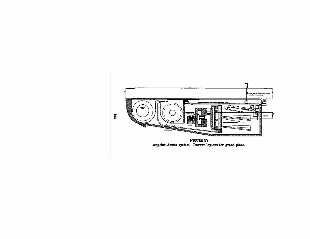
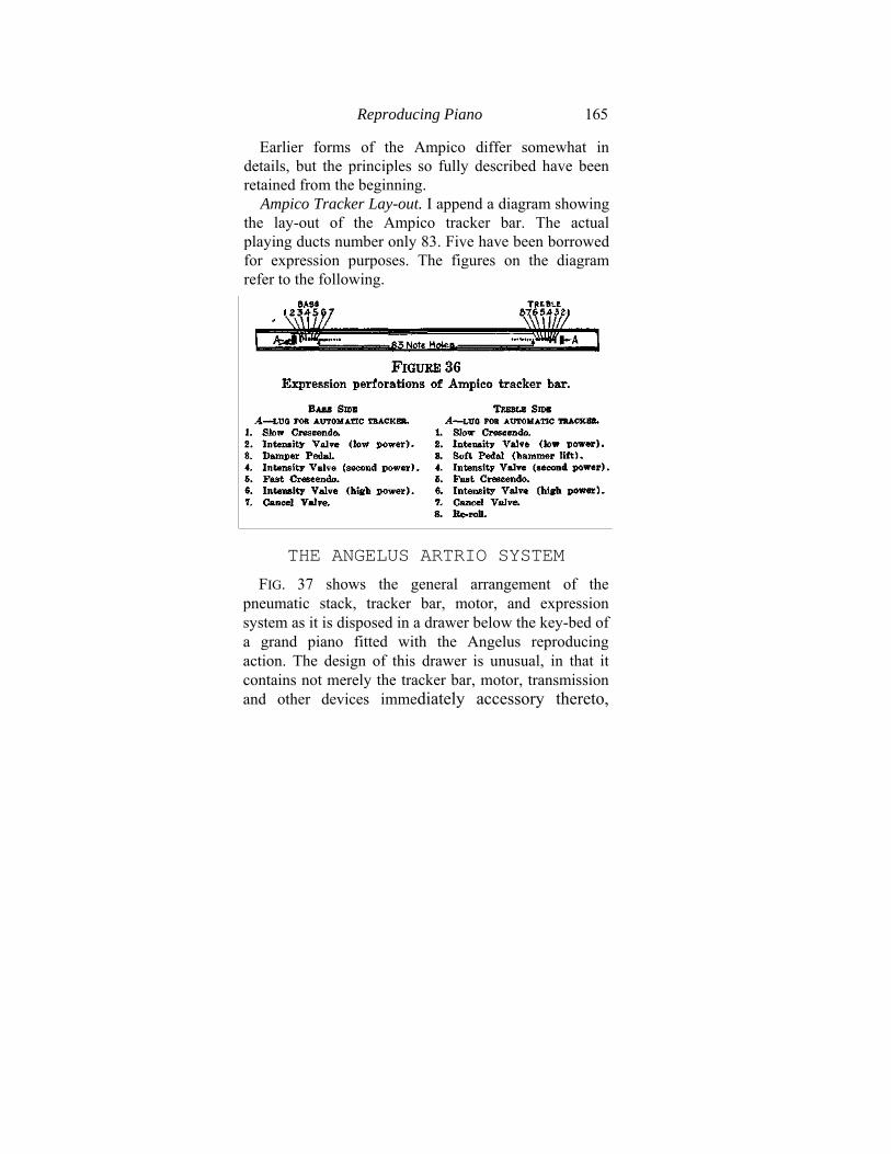
Reproducing Piano 165
Earlier forms of the Ampico differ somewhat in details, but the principles so fully described have been retained from the beginning.
Ampico Tracker Lay-out. I append a diagram showing the lay-out of the Ampico tracker bar. The actual playing ducts number only 83. Five have been borrowed for expression purposes. The figures on the diagram refer to the following.
THE ANGELUS ARTRIO SYSTEM
FIG. 37 shows the general arrangement of the pneumatic stack, tracker bar, motor, and expression system as it is disposed in a drawer below the key-bed of a grand piano fitted with the Angelus reproducing action. The design of this drawer is unusual, in that it contains not merely the tracker bar, motor, transmission and other devices immediately accessory thereto,
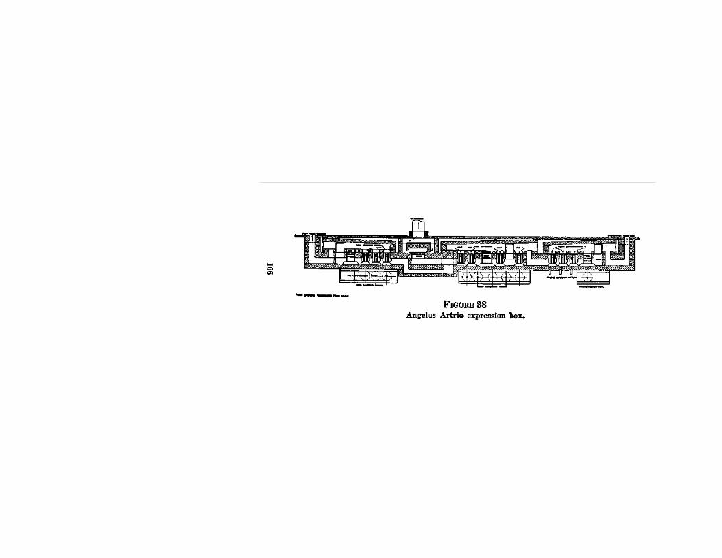
Reproducing Piano 167
but also houses the pneumatic stack itself and the expression system, which is placed between the stack and the tracker bar. Thus, when the drawer is pulled out in order that the music roll may be inserted or removed, the whole of the mechanism, with the exception of the electric-driven pump and some other minor devices, moves forward also. In order to maintain the contact of each pneumatic with the piano action, therefore, a rod pivoted at each end and adapted to rotate in a direction at right angles to the plane of the pneumatic's motion is placed between each pneumatic and the contact plunger which projects through the key-bed and makes contact with the rear end of the piano key. The pneumatic may thus make its contact in whatever position it may be.
The position of the expression control valves is also readily seen in the drawing. These, of course, are controlled by the expression perforations in the margins of the tracker bar.
Turning now to FIG. 38 we find ourselves looking downwards upon the expression box, which is cut open for inspection. At each extremity of the drawing will be seen the inlet through which the air from bass and treble sides of the divided pneumatic action, respectively, flows into the expression system, while in the middle will be observed the out-let through which all the air finally finds its way to the bellows or pump.
The three governing pneumatics may now be

168 Piano Playing Mechanisms
examined. It will be seen that the middle, or "solo," governor controls the other two, since the air which arrives from either side of the pneumatic stack must ultimately always go through this middle governor before it flows out to the pump. The other two governors operate on the treble and bass halves of the pneumatic stack, respectively, under the ulti-mate control of the solo governor, as described. Operation of the System. The operation of the
system is easy to understand. In the first place, let us suppose that all the expression perforations in the tracker bar are sealed. Then as the music roll unwinds, air from bass and treble sides flows into the bass and treble governors, respectively. To pass out of either governor this air must pass out to the middle or solo governor, and in the case specified, through the pianissimo opening. When it arrives at the entrance to the governor it must then pass to the pump by means of the "minimum soft" opening, the position of which is indicated plainly in the drawing. The springs which keep the three governors open will regulate the size of each of these pianissimo openings and, in practice, will be regulated so that the playing power is very low. We begin, therefore, with the understanding that when all expression perforations in the tracker bar are closed the playing is at a minimum power.
Glancing now at the side governors, bass and treble, we note that each carries a large or "melody" opening and three small ones which, in fact, are
Reproducing Piano 169
no larger than vents, and are so named in the drawing. Suppose that we wished to play very softly and at the same time have the accompaniment in the bass still softer than the melody in the treble. Then we should allow the melody opening in the treble governor to be open so that the air from the treble side of the action should flow into the solo (middle)) governor through this large opening, while on the bass, or accompaniment side, we should allow either the pianissimo opening alone to be available or else should open up one, or two, or all three of the bass governor vents. The more of them opened the louder would be the accompaniment in comparison with the melody, which latter would be operating on the large melody opening. Thus, by combining the expression perforations in the music roll to operate at any moment so many of the bass governor vents as we might wish, we could obtain at that moment any one of several possible degrees of tone-strength difference between the bass and treble sides of the action. Of course, just as easily the process may be reversed and the louder side be the bass side. It is all a question of what expression ducts are used and of how long each is kept open by the perforations in the music roll.
Meanwhile, it will be remembered that we are pulling the air only through the minimum opening of the controlling or solo governor. This, however, can be altered by employing one, two, three, or all of the small vents in the solo governor, which by
170 Piano Playing Mechanisms
their operation will build up the general level of power while not interfering with the relative playing strength of the two sides of the action, as determined by the side governors. For a very loud crash the big melody opening of the solo governor is used.
Thus it will be seen that everything depends upon the use made of the thirteen expression openings, five of which are in the controlling governor, four in the treble governor, and four in the bass governor.
Tracker Bar Connections. Each of the valves shown, of course, is connected with a corresponding duct in the margin of the tracker bar. Each valve, as shown in PIG. 38, is kept down on its seat by atmospheric pressure. When an expression perforation in the music roll registers with the corresponding tracker duct, air flows down through the tube, lifts the valve and thus cuts off the atmospheric pressure which has been holding a pouch down upon the shaft of the vent or of the melody opening, as the case may be. Hence, the pouch no longer holds the vent or melody opening shut and permits a flow of air through it.
The middle, or solo governor, controls the general playing level and the side governors control the relative power of the bass and treble sides. This being the case only one set of tracker ducts is needed to control the accompaniment playing at any time, for whichever side is being used as a melody
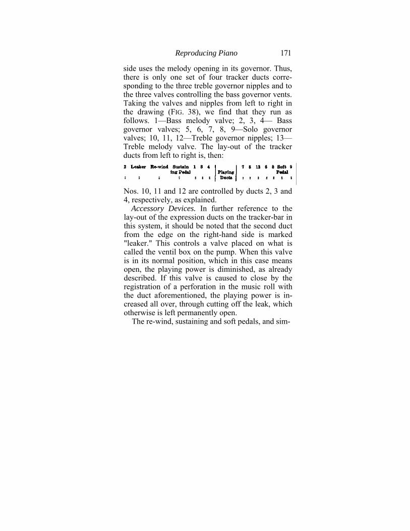
Reproducing Piano 171
side uses the melody opening in its governor. Thus, there is only one set of four tracker ducts corre-sponding to the three treble governor nipples and to the three valves controlling the bass governor vents. Taking the valves and nipples from left to right in the drawing (FIG. 38), we find that they run as follows. 1—Bass melody valve; 2, 3, 4— Bass governor valves; 5, 6, 7, 8, 9—Solo governor valves; 10, 11, 12—Treble governor nipples; 13— Treble melody valve. The lay-out of the tracker ducts from left to right is, then:
Nos. 10, 11 and 12 are controlled by ducts 2, 3 and 4, respectively, as explained.
Accessory Devices. In further reference to the lay-out of the expression ducts on the tracker-bar in this system, it should be noted that the second duct from the edge on the right-hand side is marked "leaker." This controls a valve placed on what is called the ventil box on the pump. When this valve is in its normal position, which in this case means open, the playing power is diminished, as already described. If this valve is caused to close by the registration of a perforation in the music roll with the duct aforementioned, the playing power is in-creased all over, through cutting off the leak, which otherwise is left permanently open.
The re-wind, sustaining and soft pedals, and sim-
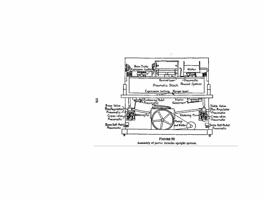
Reproducing Piano 173
ilar devices are easily identified and offer no particular, novelties. The same may be said of the pump. Manual controls are also included in this system. There are manual buttons to throw on the melody openings at will, and also a crescendo lever which brings on all the solo governor vents in turn by opening up air passages to the controlling valves. The operation of all these manual devices is obvious in each case. Sustaining pedal, soft pedal and tempo control levers are also included. Detailed instructions on the testing and regulating of this system are, of course, given in the usual technical manual which the makers issue. A special test roll goes with the manual.
THE ARTECHO SYSTEM (AMPHION PIANO PLAYER COMPANY)
This system depends upon the control of a regulator valve (called in Artecho terminology, the governing valve) inside the main air-flow passageway from pneumatic stack to pumping plant. The pneumatic stack is divided into two halves, and one set of expression mechanism is allotted to each. The assembly drawing (FIG. 39) shows the lay-out.
Looking now at FIG. 40 we see that the main features are three in number. There is first a valve block containing various valves connected with the tracker bar marginal ducts. In the upright Artecho this block is placed on top of the pneumatic stack.
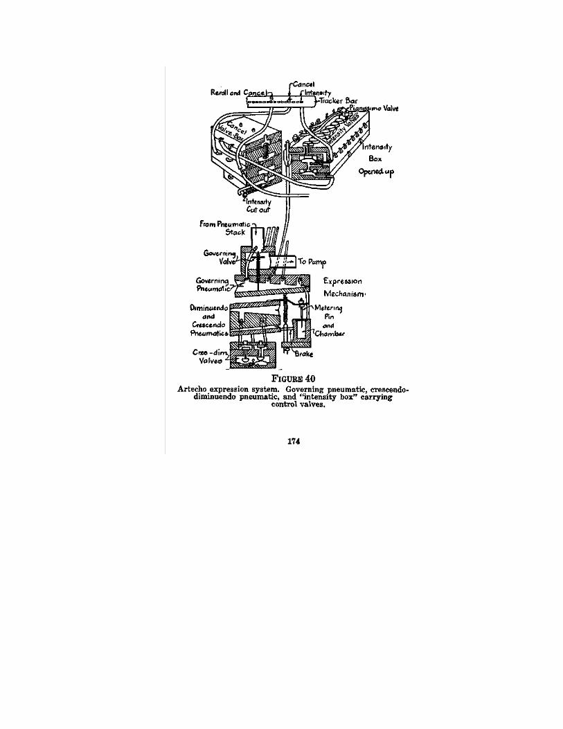
Reproducing Piano 175
Pneumatically connected with this valve block and underneath the key-bed in the upright Artecho is a regulator pneumatic, the air in which is normally at low pressure (partial vacuum). A connecting tube running into the main air-way provides the needed suction power. The further the regulator pneumatic collapses under this suction power the further it pushes upwards the governing valve and closes off the main air-way. Consequently, when this governing pneumatic is collapsed as far as it can go, (the extent being subject to the resistance of the coiled tension spring), it has the air-way nearly blocked off, so that the playing power is very low, the air pressure being nearly atmospheric. The spring resistance regulates the precise pressure attained.
To secure any accent or crescendo, therefore, above this pianissimo it is necessary to bleed atmo-spheric air into this regulator pneumatic, which is accomplished through the operation of the intensity valves under the control of the marginal per-forations in the tracker bar and music roll. • Crescendo - Diminuendo System in Artecho. Before we go to the intensity valves, however, let us look at the crescendo-diminuendo system. This consists of a double pneumatic with a valve system containing one valve to each side of the double unit. The moving wall of the upper half of the pneumatic carries a rod which, in turn, connects with a tapered pin (called in Artecho terminology, a metering
176 Piano Playing Mechanisms
pin) moving in and out of a round hole into an air chamber which, in turn, is connected with the regulator pneumatic. Obviously, if the double pneumatic is at normal, that is, with each half exhausted of air, it will hold the tapered metering pin at middle position, allowing just a little air to flow past it into the air chamber below it.
Should the lower half of the double pneumatic, that is, the diminuendo half, be caused to expand by air entering through the tracker ducts (marginal) by way of the intensity valve corresponding, the expansion of this half of the double pneumatic will drawn down the metering pin and shut off atmosphere from the regulator pneumatic, which will tend to close and to affect the governing valve accordingly.
Per contra, when the upper or crescendo half of the double pneumatic is similarly affected through its duct and valve, the upper half will expand and lift out the metering pin, allowing an increasing flow of atmosphere into the governing pneumatic.
In the first place, the playing power will be cut down. In the second place, it will be increased.
The drawing (FIG. 40) shows the metering pin mechanism to be provided with a rod which acts as a friction brake to prevent a too sudden movement of the pin.
Artecho Intensity Box. The foregoing system is controlled by an intensity box (to use the Artecho terminology) which, in the upright models, is to be
Reproducing Piano 177
found on the bass side above the pneumatic stack. This is a valve chamber containing six intensity valves, three for bass and three for treble, with three cancel valves and pouches to match. It also carries valves for the hammer-lift rail, bass and treble, and for the pianissimo adjustment.
When one of the expression perforations in the music roll registers with the corresponding duct in the right or left margin of the tracker bar, the intensity valve corresponding at once rises and permits a certain amount of atmosphere to flow down through what is called the manifold into the regulator pneumatic, previously described. The precise amount of this inflow is regulated for each valve by means of a screw adjustment. The larger the inflow the higher the playing pressure in the pneumatic stack, because of the corresponding position of the governing valve.
Pianissimo is governed by a very simple device. A certain amount of air is always admitted to the regulator pneumatic through a special tube, working through over the top of the intensity box. But if this is cut off by means of a rising valve operated by the pianissimo duct in the tracker, under the control of the music roll, this air is cut off, so that the governing pneumatic closes until nothing keeps the governing valve from shutting off completely the main air passage, save only the resistance of the tensioning spring.
Lock-Cancel System. A locking-canceling sys-
178 Piano Playing Mechanisms
tern is also used in the intensity box in order to avoid employing awkwardly long intensity perforations in the roll. When the intensity valve rises it admits air under its head in two directions, one down the manifold to the governing pneumatic, and the other under its own pouch and simultaneously over a pouch immediately below its own pouch. This, however, is kept pressing upwards against the under side of the aforementioned channel from the intensity valve head by means of air flowing from an open port at the top of the intensity box. Thus the intensity valve is kept open, although the original cause of its rising, namely, the music roll perforation, has passed over. When, however, the cancel perforation comes over and registers with the cancel duct in the tracker bar, a cancel valve rises and cuts off this air flow under the cancel pouch, which drops, under the pressure of the atmosphere above it and so, in turn, causes the in-tensity valve to drop. In this way a cancel perforation at intervals takes the place of otherwise long slots in the music roll.
It can readily be seen that by properly adjusting the size of the air-admission ducts in the manifold the air flow of the regulator pneumatic can be delicately controlled. In practice the measurement is done by a water gauge, as is now almost the universal method in reproducing piano regulating. Each intensity valve may therefore be most finely regulated to give the precise needed quantity of
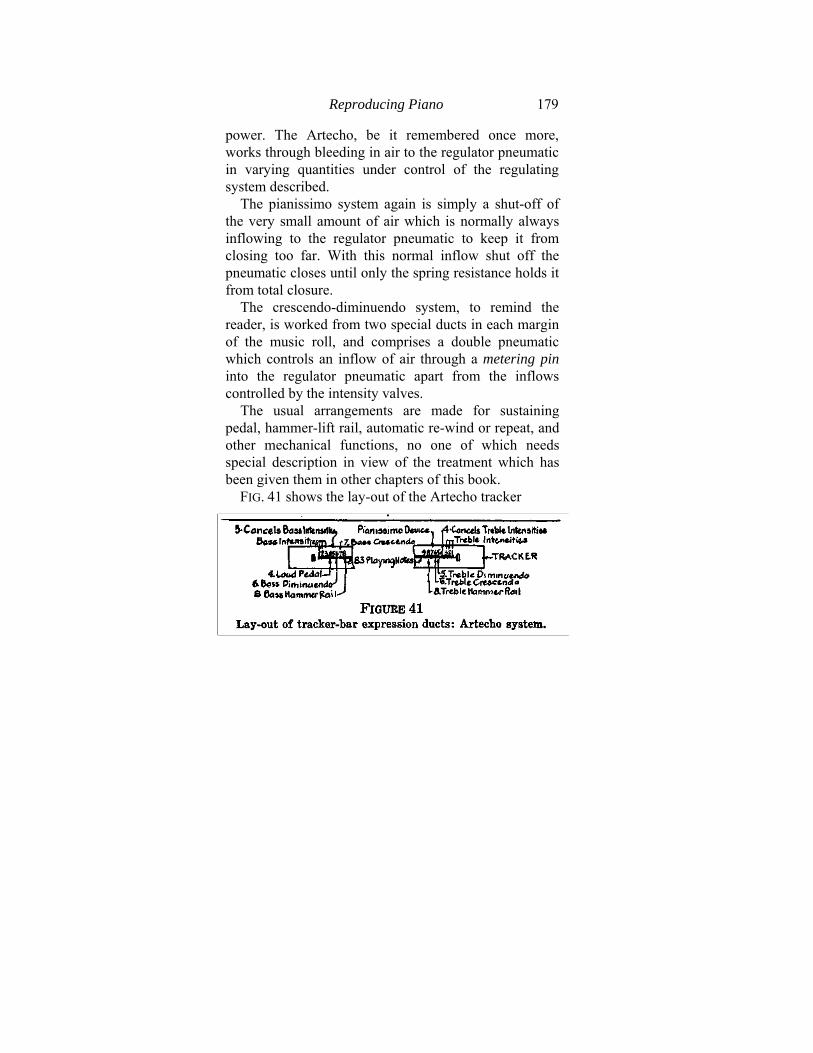
Reproducing Piano 179
power. The Artecho, be it remembered once more, works through bleeding in air to the regulator pneumatic in varying quantities under control of the regulating system described.
The pianissimo system again is simply a shut-off of the very small amount of air which is normally always inflowing to the regulator pneumatic to keep it from closing too far. With this normal inflow shut off the pneumatic closes until only the spring resistance holds it from total closure.
The crescendo-diminuendo system, to remind the reader, is worked from two special ducts in each margin of the music roll, and comprises a double pneumatic which controls an inflow of air through a metering pin into the regulator pneumatic apart from the inflows controlled by the intensity valves.
The usual arrangements are made for sustaining pedal, hammer-lift rail, automatic re-wind or repeat, and other mechanical functions, no one of which needs special description in view of the treatment which has been given them in other chapters of this book.
FIG. 41 shows the lay-out of the Artecho tracker
180 Piano Playing Mechanisms
bar, and should be studied carefully in connection with the foregoing descriptions.
The Artecho mechanism is also known as the Celco Reproducing Medium.
THE DUO-ART SYSTEM (AEOLIAN COMPANY)
The Duo-Art system shows an interesting variation upon the themes that have been discussed. Its principal mechanical difference lies in the fact that the pneumatic stack—which is divided into two parts, as usual, bass and treble—is controlled by the divided expression system under two different foundation working pressures. That is to say, the expression system is divided for playing purposes into a melody side (called theme side in Duo-Art terminology) and an accompaniment side, each having its regulator pneumatic set at a different adjustment, so that the foundation or zero power (the lowest playing power) is always a little stronger on the former than on the latter. This is natural enough from a practical standpoint, since melody is usually louder than accompaniment even when both are near their lowest possible strengths.
Otherwise, the two sides are exactly alike. The theme side is the treble or right-hand side (on an upright) and the accompaniment side is the other, but arrangements are made whereby either side can control the opposite side of the pneumatic stack.
Reproducing Piano 181
The theme side can operate on the bass half of the stack and the accompaniment on the treble, when required. Or the whole stack can be controlled by either side. The division is made between notes 43 and 44 on the keyboard.
Knife-Valve Control. The expression system depends upon two knife valves which are fundamentally adjusted with reference to their air passageways by the foundation or zero pneumatics, which in a way correspond with the regulator pneumatics of the other systems previously described. Additional adjustments for accents or crescendo-diminuendo effects are obtained by additional pull on the knife valves on each side, as is done in all reproducing systems. The Duo-Art method is, however, sufficiently individual to repay careful study.
FIG. 42 shows in diagrammatic form, but not to scale or in exact order of installation, the principles of the system. It will be seen that the tracker bar contains the usual marginal expression perforations, certain of which are placed above Nos. 1 to 4 of the playing ducts on the bass side and above ducts Nos. 85-88 on the treble side. These extreme bass and treble ducts are cut off from any function when the Duo-Art is on, by means of the usual cutoff lever. Such levers or cut-off arrangements are al-ways found in reproducing pianos, since it is desirable to excise the automatic playing mechanism sometimes, in order to use ordinary music rolls.
Tracker Lay-out. It will also be observed that
182 Piano Playing Mechanisms
the tracker bar contains on each side, in addition to the usual re-roll, sustaining pedal and soft pedal ducts, four ducts placed above the extreme playing ducts, as noted in the previous paragraph, and one additional duct outside these on each side. The four first mentioned control the four dynamic devices, and the outside one the on or off of the theme control for that side of the action. In other words, when the theme duct is opened, whether on treble or bass side of the tracker, the corresponding side of the pneumatic stack is controlled through the theme side of the expression system. This, as said before, can be applied to either bass or treble, or to both simultaneously.
Dynamic System. The expression box contains the foundation regulator or zero pneumatics, one on each side, and also the corresponding jack-knife valves. This box is mainly a system of channels, as may be seen. The accordion dynamics, as they are called in Duo-Art terminology, are two sets of four pneumatics each, corresponding with the tracker ducts mentioned above, and numbered correspondingly in the illustration. Each, as can at once be seen, works through a valve to which the air from the tracker duct goes in the first instance, and each is so adjusted that it collapses a little further than the one above it. In fact, the highest one collapses one-sixteenth of an inch, the next one-eighth of an inch, the next one-quarter of an inch, and the last one-half of an inch. If all are made
Reproducing Piano 183
to collapse together the total movement effected upon the jack-knife valve is fifteen-sixteenths of an inch. It is obvious that if these pneumatics are used in combinations—one- two, three or four at a time— no less than fifteen separate combinations can be obtained, each differing from any other by a greater or lesser amount. Moreover, it is plain that either the theme side or accompaniment side can be treated separately. Lastly, when it is remembered that the jack-knife valve on the accompaniment side is adjusted by the regulator, or zero pneumatic, to close normally a little more than the other one, it can be seen how great variety is obtained. The Duo-Art therefore does not include any crescendo system of the type previously described.
The Spill Valve. Further, it should be noted that the air flow from either side of the pneumatic stack to the pumping plant is normally reduced in volume by a continuous slight air inflow through what is called a spill valve, but which might more conveniently be termed a "bleed-in." This, as may be perceived, is adapted to be gradually shut off by means of a knife-valve, which also works in accord with the motion of the main knife valves on each side by means of rocker arms. At a certain point, that is, when by combination of No. 2 and No. 8 accordion dynamics, the knife valve opens on either side of the extent of %-inch, the knife valve on the in-bleed, or spill, closes entirely and remains closed
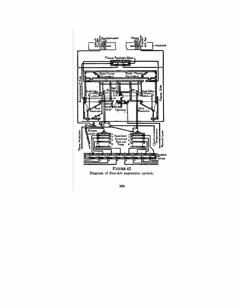
Reproducing Piano 185
during any still higher combinations of the accordion dynamics.
In making the diagram of this system (FIG. 42) all features have been omitted which do not contribute to an understanding of the principle followed. Thus, the cut-off block is left out, and the reader must understand that this is a box through which all air passes between the marginal tracker perforations and the dynamic valves. This box, when one shifts a lever, shuts off all the Duo-Art connections so that an ordinary 88-note roll can be played. It also throws in the borrowed playing ducts, as described above.
Let it also be noted that connected with the theme perforations in the tracker bar are primary valves which, in turn, run to secondary valves, each of which normally shuts an opening into one of the trunk channels of the expression box. We may now consider the working of the system as a whole.
Working of the System. We begin with the ac-companiment side. If neither the accompaniment nor the theme tracker duct is opened by the paper, the air from the pneumatic stack on each side (bass and treble) enters the top channel of the expression box, passes through the flap valves and goes out through the port to the "accompaniment" passageway, thence past the accompaniment regulator knife valve to the pump. Obviously, the precise rapidity of the out-flow of air to the pump will depend upon the position of the knife valve, which
186 Piano Playing Mechanisms
in turn, will depend upon the accordion dynamics on the accompaniment side. These may be in use (controlled by the tracker-bar and music roll) in any one of the possible combinations previously mentioned, and so the accompaniment regulation may be at any one of sixteen (including the zero) possible stages of loudness. If neither one of the theme ducts in the tracker are opened, this accompaniment regulation will control the whole keyboard.
Suppose now that while the bass theme duct remains closed the treble theme duct is opened by the music roll. At once the atmosphere admitted through this duct throws the treble theme primary valve, which, in turn, pulls down the corresponding secondary valve in the expression box. Air flowing into this box from the treble side of the pneumatic stack is therefore caused to flow out over the head of the dropped secondary valve and thence into the theme regulator passageway, past the knife valve. The precise position of this valve will at any moment be under the control either of the zero or foundation pneumatic or of any one, or group, of the accordion dynamics on the theme side.
On the other hand, if the treble theme duct remains closed, air flow from the treble side goes through the accompaniment side of the expression box and, if simultaneously the bass theme duct is opened, the bass air flows through the theme regulator.
Reproducing Piano 187
Summary of Duo-Art System. The Duo-Art system, then, comprises the combination of two separate fundamental levels of power, each subject to an individual set of step-controls through its accordion dynamics. These latter can be manipulated by the music roll through perforations and tracker ducts. "Accompaniment" and "theme" are convenient names, but in reality the situation will be clearer if we simply remember that the two sides of the expression system are interchangeable, or rather inter-applicable, and that each operates under its own individual foundation power level, the one slightly lower than the other.
The Duo-Art, like other reproducing systems, can be operated through hand, or finger, levers. These, in the present case, are duplex. One, called the "temponamic" is a combination of tempo lever and mechanical knife-valve manipulator. It operates only on the accompaniment section of the expression. The "theme modulating" lever, as it is called, operates on the theme side, but has no effect except when the bass or treble, or both, release levers are kept open. These levers admit air to the theme primary valves on their corresponding (bass or treble) sides and thus permit the theme modulator to have effect on one side, while the accompaniment through the Temponamic controls the other side. The theme control can be exerted over the whole keyboard by opening both release levers, or by leaving both alone; the Temponamic lever can control

188 Piano Playing Mechanisms
the whole keyboard from the foundational pressure of the accompaniment regulator.
THE WELTE - MIGNON (ORIGINAL) SYSTEM
This mechanism is manufactured by the Welte-Mignon Corp. of New York, and is by them termed the "Original Welte-Built Welte-Mignon." It represents the contemporary development of the original mechanism devised in Germany by M. Welte & Son of Freiburg, first seen in the United States during the year 1007. The other, or Welte (Licensee) reproducing piano action, is controlled and manufactured by the Auto-Pneumatic Action Co., of New York, under a license issued by the owners of the Welte patent rights. As between the two there are certain differences of construction, which will become clear upon comparison of the descriptions given in this book.
The Welte mechanism now under discussion is built in three forms: (1) as a separate action enclosed in a cabinet which may be rolled up in front of the keyboard of a piano and which co-acts with the keys through striking fingers attached to the pneumatics; (2) as an interior built-in action for the grand piano; and (3) as an interior built-in action for the upright piano. The mechanism itself, of course, save for the special adaptations necessary in each case, is the same for all three in principle and in construction.
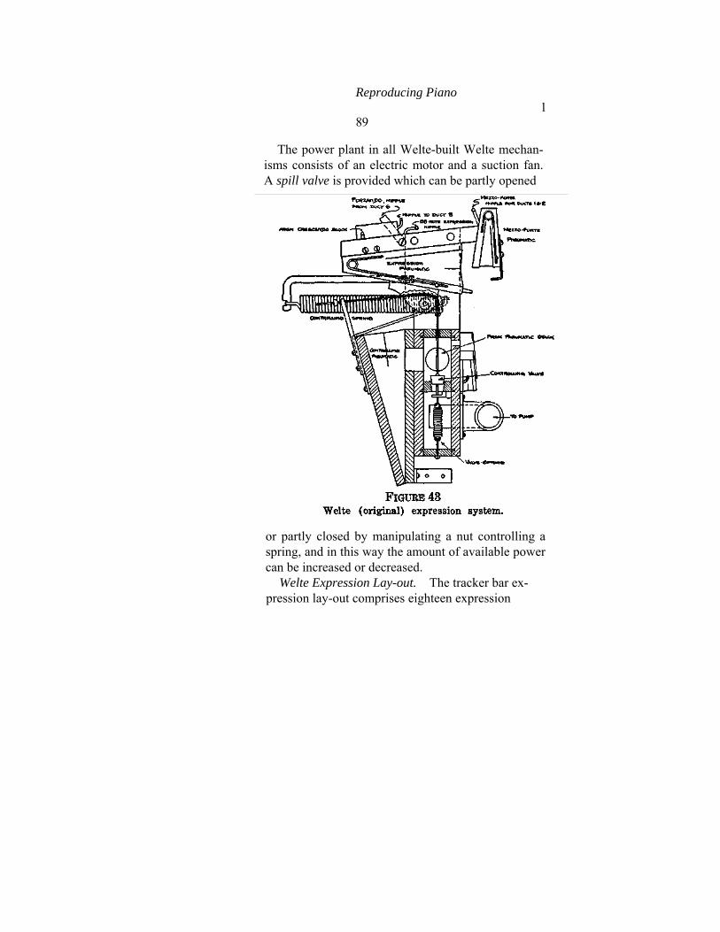
Reproducing Piano 189
The power plant in all Welte-built Welte mechan-isms consists of an electric motor and a suction fan. A spill valve is provided which can be partly opened
or partly closed by manipulating a nut controlling a spring, and in this way the amount of available power can be increased or decreased.
Welte Expression Lay-out. The tracker bar ex-pression lay-out comprises eighteen expression
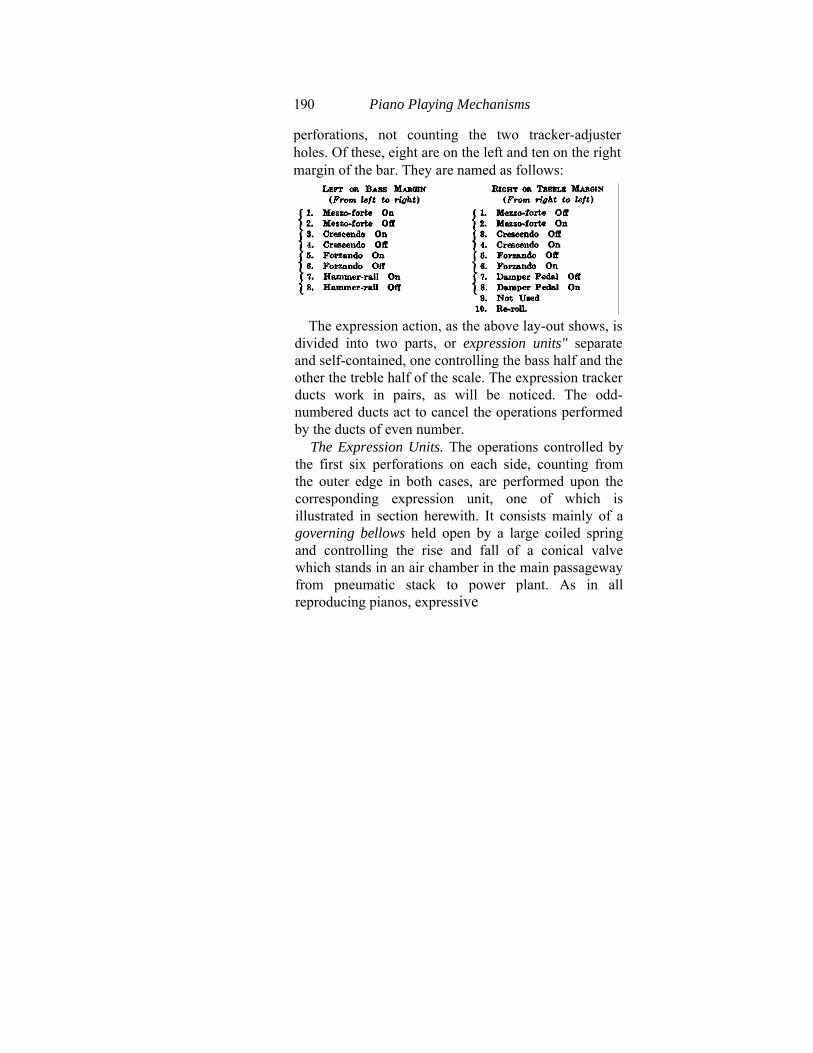
190 Piano Playing Mechanisms
perforations, not counting the two tracker-adjuster holes. Of these, eight are on the left and ten on the right margin of the bar. They are named as follows:
The expression action, as the above lay-out shows, is
divided into two parts, or expression units" separate and self-contained, one controlling the bass half and the other the treble half of the scale. The expression tracker ducts work in pairs, as will be noticed. The odd-numbered ducts act to cancel the operations performed by the ducts of even number.
The Expression Units. The operations controlled by the first six perforations on each side, counting from the outer edge in both cases, are performed upon the corresponding expression unit, one of which is illustrated in section herewith. It consists mainly of a governing bellows held open by a large coiled spring and controlling the rise and fall of a conical valve which stands in an air chamber in the main passageway from pneumatic stack to power plant. As in all reproducing pianos, expressive
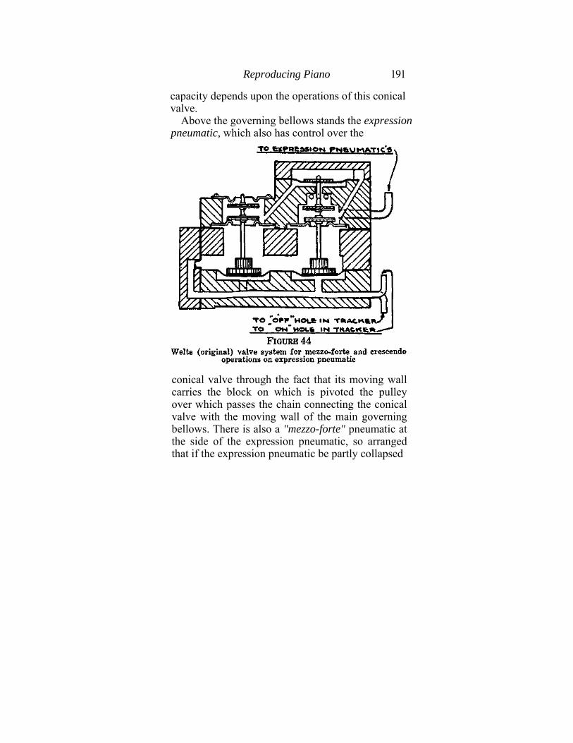
Reproducing Piano 191
capacity depends upon the operations of this conical valve.
Above the governing bellows stands the expression pneumatic, which also has control over the
conical valve through the fact that its moving wall carries the block on which is pivoted the pulley over which passes the chain connecting the conical valve with the moving wall of the main governing bellows. There is also a "mezzo-forte" pneumatic at the side of the expression pneumatic, so arranged that if the expression pneumatic be partly collapsed

192 Piano Playing Mechanisms
the mezzo-forte pneumatic, by also collapsing, may hold the expression pneumatic from closing any further. The illustration shows the facts plainly, and may be compared with the corresponding drawing of the Welte (Licensee) action.
The operations of the expression pneumatic and of the
mezzo forte pneumatic are controlled by the marginal expression ducts of the tracker bar, as may be seen by comparing the drawings with the listed numbers and functions of these ducts, as given above. Between pneumatics and ducts intervene the valve block, of which is shown here a cross-section in two parts (See FIGS. 44 and 45).

Reproducing Piano 193
Of course, again there are two such valve blocks in the action, one for the bass and one for the treble expression unit. Tracing the tubes from the tracker-bar we note that, counting from left to right on the bass and from right to left on the treble block, the first pair co-acts with ducts Nos. 1 and 2 on the mezzo-forte pneumatic, while Nos. 3 and 4 co-act with the corresponding ducts and deal with the expression pneumatic for slow-closing or crescendo, and Nos. 5 and 6 deal with the rapid-closing, or for-zando. Further, still, to the left of the valve block is the "88-note" control, which deals with the expression pneumatic by means of a hand-controlled air-admitting button, whereby, when non-expression rolls are used, the expression may be controlled by the player-pianist personally.
Expression Valve Blocks. Valves used for those operations on the expression pneumatic, which have been described as mezzo-forte and crescendo, that is, which are worked through tracker ducts 1-2 and 3-4, as well as the work done through the finger buttons with non-expression rolls, are built as shown in FIG. 44. Operations on the forzando, or rapid closing of the expression pneumatic, %re done through a valve of another kind, as shown in FIG. 45. These last are the operations controlled by tracker ducts Nos. 5 and 6.
Operation of Expression Pneumatic. The governing bellows or pneumatic opens or closes more or less according to the pneumatic load on the action
194 Piano Playing Mechanisms
as determined by the number of pneumatics operating at any moment, and thus pulls up or down on the conical valve, maintaining the passageway for the air flow at the right size. The expression pneumatic, on the other hand, has the function of altering suddenly or slowly, according to the co-incidence from moment to moment of expression perforations in the paper with the tracker ducts, the size of that passageway, by sudden (forzando) or slow (crescendo) pulls on the conical valve, corre-sponding to sudden or gradual collapses of itself, governed by the large (forzando) or small (crescendo) nipples through which air can flow out of it. The expression pneumatic is normally open and the conical valve is therefore normally at its lowest position, so that the playing power is normally minimum. The operations noted above consist of letting air flow out of the expression pneumatic slowly or rapidly, as the case may be (according to the nipple used, as mentioned above), and this is governed by the arrangement of the expression perforations in the music roll which register with tracker ducts Nos. 1 and 6 on either bass or treble side.
Tracker ducts Nos. 7-8 on the bass side control the operation of the hammer-rail pneumatic, and ducts Nos. 7-8 on the treble side perform the same function for the damper-lift or loud-pedal pneumatic. A special valve block contains the valves for these two pneumatics.
In the equalizer system there is a special addi-
Reproducing Piano 195
tional small equalizer or pressure governor connected with the two expression valve-block units for the purpose of steadying the tension under which they work. There are also two "volume-control" pneumatics, operating cut-offs in the equalizer system and controlled by a lever in the spool box. The object is to cut down or increase the general loudness of playing for special purposes, at the will of the owner of the instrument.
The re-roll is managed automatically through duct No. 10 on the treble margin of the tracker bar. A re-playing device is also included, which permits the constant operation of the re-roll device at the end of each re-roll of a music roll.
THE WELTE (LICENSEE) SYSTEM (AUTO PNEUMATIC ACTION COMPANY)
The Welte (Licensee) system depends upon a divided pneumatic stack, like the others, each side of which is governed by an expression system comprising a pressure regulator (governor pneumatic, as it is called in FIG. 47), an expression pneumatic, which controls the former, and a stop pneumatic which, for certain special purposes, limits the action of the expression pneumatic. Each ex-pression set is caused to operate by a set of four valves controlled through the tracker. The general assembly of the mechanism, as in an upright model, is shown herewith and needs no special further
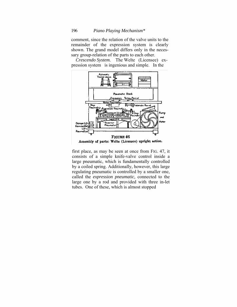
196 Piano Playing Mechanism*
comment, since the relation of the valve units to the remainder of the expression system is clearly shown. The grand model differs only in the neces-sary group-relation of the parts to each other.
Crescendo System. The Welte (Licensee) ex-pression system is ingenious and simple. In the
first place, as may be seen at once from FIG. 47, it consists of a simple knife-valve control inside a large pneumatic, which is fundamentally controlled by a coiled spring. Additionally, however, this large regulating pneumatic is controlled by a smaller one, called the expression pneumatic, connected to the large one by a rod and provided with three in-let tubes. One of these, which is almost stopped
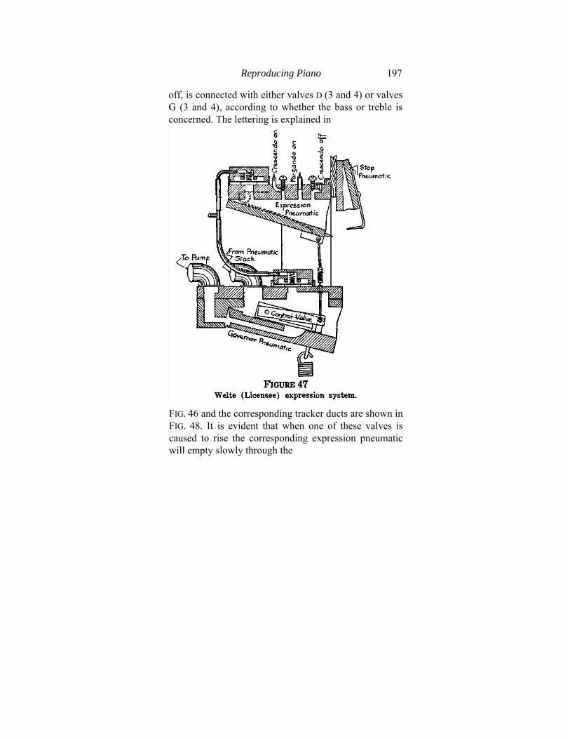
Reproducing Piano 197
off, is connected with either valves D (3 and 4) or valves G (3 and 4), according to whether the bass or treble is concerned. The lettering is explained in
FIG. 46 and the corresponding tracker ducts are shown in FIG. 48. It is evident that when one of these valves is caused to rise the corresponding expression pneumatic will empty slowly through the
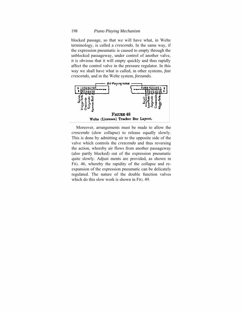
198 Piano Playing Mechanism
blocked passage, so that we will have what, in Welte terminology, is called a crescendo. In the same way, if the expression pneumatic is caused to empty through the unblocked passageway, under control of another valve, it is obvious that it will empty quickly and thus rapidly affect the control valve in the pressure regulator. In this way we shall have what is called, in other systems, fast crescendo, and in the Welte system, forzando.
Moreover, arrangements must be made to allow the
crescendo (slow collapse) to release equally slowly. This is done by admitting air to the opposite side of the valve which controls the crescendo and thus reversing the action, whereby air flows from another passageway (also partly blocked) out of the expression pneumatic quite slowly. Adjust ments are provided, as shown in FIG. 46, whereby the rapidity of the collapse and re-expansion of the expression pneumatic can be delicately regulated. The nature of the double function valves which do this slow work is shown in FIG. 49.
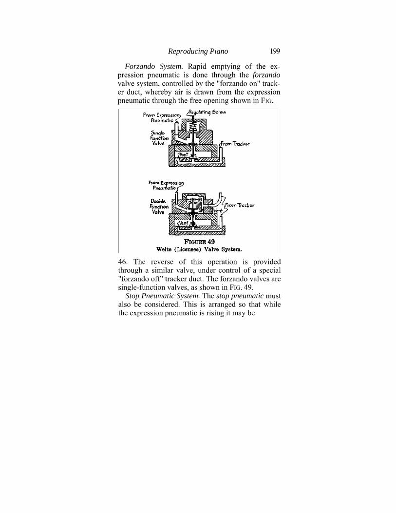
Reproducing Piano 199
Forzando System. Rapid emptying of the ex-pression pneumatic is done through the forzando valve system, controlled by the "forzando on" track-er duct, whereby air is drawn from the expression pneumatic through the free opening shown in FIG.
46. The reverse of this operation is provided through a similar valve, under control of a special "forzando off" tracker duct. The forzando valves are single-function valves, as shown in FIG. 49.
Stop Pneumatic System. The stop pneumatic must also be considered. This is arranged so that while the expression pneumatic is rising it may be
200 Piano Playing Mechanisms
caught by the stop pneumatic's collapse, whereby a hook in the one engages a hook in the other, as shown. The object of this is to prevent the expression pneumatic from rising or from dropping further than a given point. In this manner further flexibility is given to the dynamic control. The proper working of this device depends upon the very careful placement of the music roll perforations which control the mezzo-forte ducts in the tracker, as they are called, and the similarly named valves.
FIG. 48 shows the lay-out of the Welte (Licensee) tracker bar, and shows what ducts correspond to what valves, according to the lettering placed on the latter in FIG. 46.
Thus it is possible to describe the operations of the Welte (Licensee) expression system by saying that the governor pneumatic maintains the working pressure at whatever level it may be set from moment to moment by the expression pneumatic.
The Tracker Bar. Examination of FIG. 49 will show that there are 80 playing ducts when the mechanism is operating, and that eight of the usual eighty-eight, therefore, are borrowed for expression purposes. It will also be noted that the hammer-rail lift and the sustaining pedal pneumatics are worked from the tracker bar. The connections between the tracker bar and the valve board of the Welte (Licensee) expression system may be observed by comparing FIG. 46 with FIG. 48. In FIG. 46 the valve
Reproducing Piano 201
blocks L, A, B, C, D, E, F, G, H and I correspond to the tracker ducts as follows:
As in other systems, an electric switch is provided to throw on or off the current from the electric motor, and at the same time there is provided a cutoff pneumatic arrangement for shutting off the pneumatic stack and reversing the gears of the wind motor for re-winding. A "repeat" pneumatic is also provided, as in all other reproducing piano systems. This may be seen in FIG. 46.
The usual expression cut-off system is also pro-vided, whereby the instrument may be made to play ordinary music rolls, but the operation of this will be plainly understood upon examination, and it is unnecessary to picture it here.
A hand-lever arrangement, as shown in FIG. 46, operates the expression pneumatic and, consequently, the pressure regulator mechanically by direct contact. Thus, ordinary music rolls can be played with expression under personal control, or Welte rolls may be managed in the same way, if required. A cut-off switch admitting air to the transformer system attends to changes from automatic to manual expression when required.
202 Piano Playing Mechanisms
For the sake of clearness, illustrations (FIG. 49) are shown of the two kinds of valves used in the Welte system and mentioned above. The single-function valves are A, B, I, J, (See FIG. 46), and the double-function valves are C, D, E, F, G and H. L and E together work the sustaining pedal pneumatic, the combination being necessary in or-der to allow for the fact that the sustaining pedal tracker duct in No. 3 bass hole for Welte (Licensee) rolls and No. 8 treble hole for other rolls.
The mechanism has a pneumatic arrangement also for softening or amplifying the general level of playing to accommodate special hearing require-ments. It is operated by a finger lever in the spool box.
For clearness' sake it will be advisable to com-pare very carefully the descriptions of the two Welte systems, for the one will be found to supple-ment the other, especially in connection with the explanations of the valve systems.
Re-roll Mechanisms in Reproducing Pianos. All reproducing pianos require automatic re-rolling systems, which in most cases are combined with a repeater system, the latter being merely a reverse of the re-roll (re-wind). FIG. 50 shows how such a system may work. There-roll (re-wind) pneumatic, controlled by a valve, may be operated either by a finger lever of a tracker duct. Air in either case is admitted to the operating valve, which collapses the pneumatic. This causes the transmission to be re-
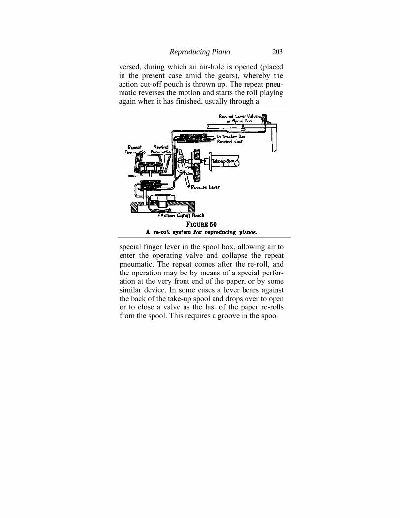
Reproducing Piano 203
versed, during which an air-hole is opened (placed in the present case amid the gears), whereby the action cut-off pouch is thrown up. The repeat pneu-matic reverses the motion and starts the roll playing again when it has finished, usually through a
special finger lever in the spool box, allowing air to enter the operating valve and collapse the repeat pneumatic. The repeat comes after the re-roll, and the operation may be by means of a special perfor-ation at the very front end of the paper, or by some similar device. In some cases a lever bears against the back of the take-up spool and drops over to open or to close a valve as the last of the paper re-rolls from the spool. This requires a groove in the spool
204 Piano Playing Mechanisms
into which the lever may drop. Many different ar-rangements of this sort are possible, but the good sense of the reader may be trusted to find out the special method adopted in each case if only the fundamental ideas are kept steadily in mind.
Purpose of this Chapter. I have purposely, as promised at the beginning of this chapter, confined these remarks on reproducing systems to such as I thought it advisable to treat because of their technical interest and their importance to the industry, which determines, of course, the probability of the reader being called upon to deal with and master their details. There are other systems in existence, some of which are very good, and some very indifferent from the mechanical point of view. The question which is, or is not, best from the artistic point of view is one it is not proposed to answer. Any discussion of the sort is without the province of a book like this. The purely mechanical side of the reproducing piano may very likely not attain any revolutionary advances for a long time to come, for the present systems have already been subjected to the broadest practical tests for a good many years. Meanwhile, the reader who has mastered the previous chapters ought to be able to understand and comprehend all the facts set forth.
Incidentally, let it be remembered that every one of the manufacturers whose names are mentioned in this chapter will be glad to supply to any qualified person copies of their technical manuals,
Reproducing Piano 205
and usually their test rolls. These manuals contain all the small detail it was thought best to omit here, and, in particular, show carefully how to use the test rolls to make the necessary mechanical adjustments in order to secure perfect musical results.
It will be objected that the present chapter is not exhaustive. The imputation is admitted. To make it exhaustive, in the sense of including every mechanism which lays claim to the title of "reproducing piano," would be to overstep the obligatory limits of its scope without any other effect than to confuse and bewilder the unfortunate reader with a multitude of details largely similar and frequently overlapping each other. What has been said in the previous pages, from the beginning of the book up to this point, should have been more than sufficient to give every attentive reader a command over the subject sufficient to enable him to dissect comprehendingly every individual system which may be presented to his notice.
CHAPTEK VI.
THE COIN-OPEEATED PLAYER-PIANO.
The discussions which have been conducted through the earlier chapters of this book will have prepared the reader to grasp the ingenious pneumatic ideas which are embodied in the coin-operated player-piano, an instrument which is really a good deal simpler than the reproducing piano. Coin-operated player-pianos, in fact, were the first successful adaptation of pneumatic playing mechanism to the interior of upright pianos. Their mechanisms have been commonly used in conditions of astounding severity, and they have therefore naturally attained to the highest degree of simplicity and effi-ciency. Essential Features of Coin-Operated Pianos. In approaching these instruments it is well to remem- ber that they consist ultimately of no more than an ordinary player-piano equipped with some simple automatic expression arrangements and pumped by an electric motor which, in turn, is controlled by a switch operated by the insertion of a coin in a slot. There are, indeed, larger and more elaborate instruments,/which include organ pipes and 206
Reproducing Piano 207
various pneumatically operated accessories, such as drums and traps, but all obey the same principles and are built up from the same bases. They are, in fact, just such player-pianos as have been described, to which have been added such accessories as are called for by special requirements of each case.
The automatic player-piano, whether actually coin-operated or not, is pre-eminently the musical instrument for places of public entertainment. As such, it lends itself naturally to various lines of expansion. It has blossomed out with organ stops, blown by the exhaust air from the player-bellows system. It has utilized all the apparatus of the drummer's pit in the theatre. It has expanded into a great brass-band type of orchestration, and even into a concert organ. Yet the player-piano has always remained at the core of the structure. The coin-operated player-piano has given birth to progeny, strange, ingenious and wonderful, and it is entitled to a most honorable place in the hierarchy of musical instruments.
The general lay-out of a typical (Seeburg) coin-operated piano is shown clearly in FIG. 51. Here are all those important parts of which the arrangement is distinctive with instruments of this class.
Motor and Drive. The first feature to be considered is the drive. This, it will be seen, is so arranged that the one electric motor works both the pump and the travel of the music roll. By means of a friction gearing the take-up spool below the
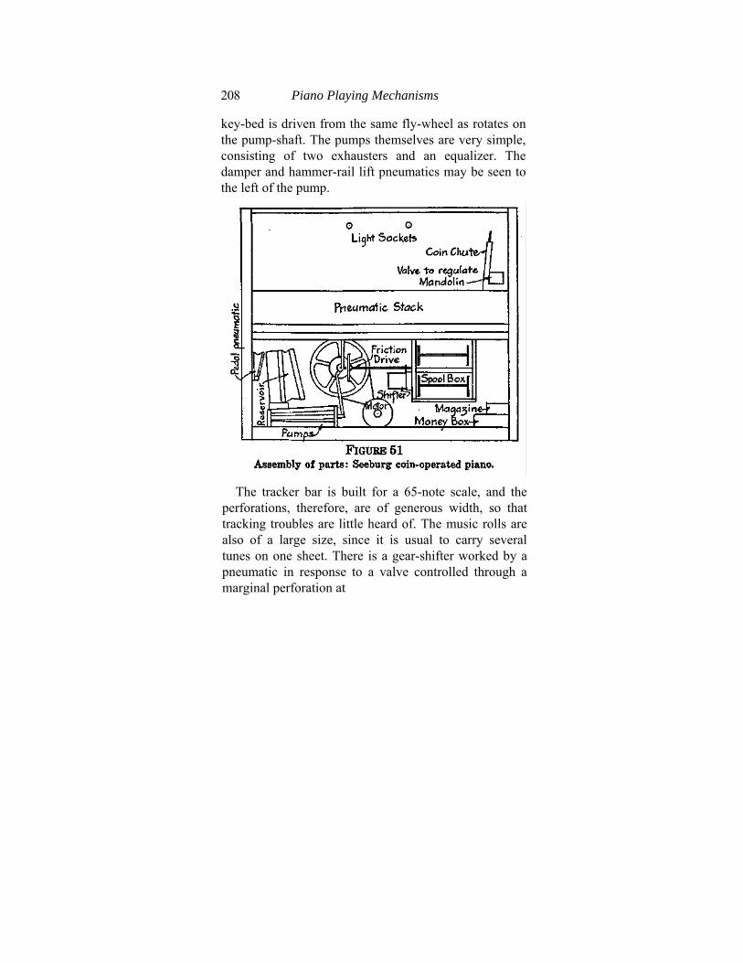
208 Piano Playing Mechanisms
key-bed is driven from the same fly-wheel as rotates on the pump-shaft. The pumps themselves are very simple, consisting of two exhausters and an equalizer. The damper and hammer-rail lift pneumatics may be seen to the left of the pump.
The tracker bar is built for a 65-note scale, and the
perforations, therefore, are of generous width, so that tracking troubles are little heard of. The music rolls are also of a large size, since it is usual to carry several tunes on one sheet. There is a gear-shifter worked by a pneumatic in response to a valve controlled through a marginal perforation at
Reproducing Piano 209
the end of the music roll. This takes care of the re-roll. There is the usual action cut-off situated, in the present instrument, behind the equalizer of the pump set.
A stop perforation in the music roll at the end of each piece of music collapses a pneumatic, which breaks the electric circuit. This circuit remains broken until another coin is dropped down the coin slot. The instrument, therefore, plays one piece only for one nickel. A magazine arrangement is also provided, by means of which more than one nickel can be inserted and the tune sheet will continue running across the tracker bar until the number of coins put in has been accounted for. A pneumatic lock is used for this purpose, and any number of nickles up to twenty can be used.
Pneumatic Stack. The pneumatic stack itself is very simple and sturdy. The vents are placed upon a separate board so that all can be cleaned out upon removal of the screws which hold this board into the front pouch board of the stack.
A softening and loudening attachment is often connected, whereby either an inleak to the main bellows can be enlarged or cut off, or some simple device operated to modify the playing pressure. Examination of each case will always show the precise method adopted.
Tracker Bar Lay-out. All the pneumatic ar-rangements, such as for re-rolling (re-winding) and repeating, for stopping and starting, will be found
210 Piano Playing Mechanisms
in the same way to yield to examination. There is nothing new or startling in any of these devices. The tracker bar lay-out differs among various makes, but in one well-known instrument (See-burg) the following arrangement has long been used. These lay-outs have been changed from time to time in accordance with mechanical and musical improvements, but every effort is used to keep them as nearly as possible uniform.
The location of the automatic expression and
operating ducts can be traced at once on almost any coin-operated instrument by mere examination.
Another interesting lay-out of parts for the coin-operated player-piano is to be seen herewith (FIG. 52) in the Coinola instrument, where the motor and pumping bellows-set are placed above the key-bed. The relation of the motor to the transmission for driving the music roll can clearly be seen, as well as the pneumatic gear-shift, the coin box and the various accessories.
Accessory Lay-out. These accessories in the case illustrated comprise a set of organ pipes, a bass drum with its pneumatics, a snare drum (removed to show parts behind it) with its pneumatics, a triangle, etc. Larger instruments contain many additional accessories, but all are operated upon the same principle and require no special description.
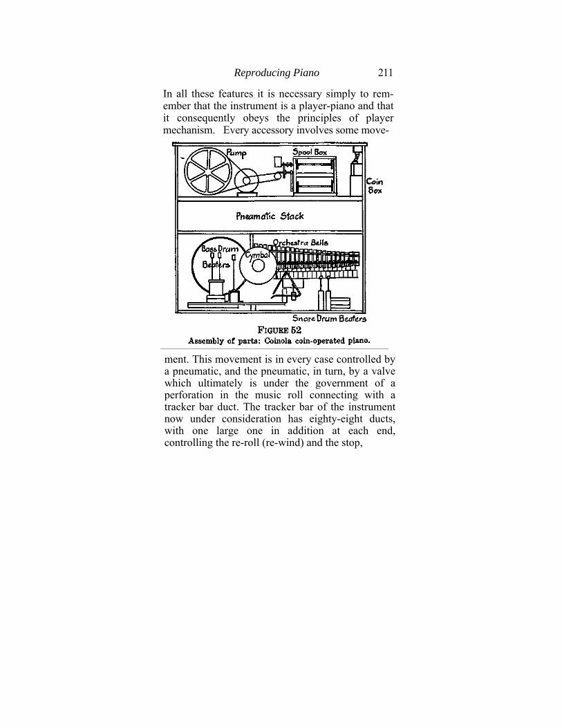
Reproducing Piano 211
In all these features it is necessary simply to rem-ember that the instrument is a player-piano and that it consequently obeys the principles of player mechanism. Every accessory involves some move-
ment. This movement is in every case controlled by a pneumatic, and the pneumatic, in turn, by a valve which ultimately is under the government of a perforation in the music roll connecting with a tracker bar duct. The tracker bar of the instrument now under consideration has eighty-eight ducts, with one large one in addition at each end, controlling the re-roll (re-wind) and the stop,
212 Piano Playing Mechanisms
respectively. There are sixty-five playing ducts, and the remaining twenty-three are utilized for working the various accessories, such as drums, triangles, xylophone, pipes, etc.
Manipulating Music Roll. In order to get at the music roll it is usually necessary in these instruments to re-roll the large sheet by collapsing the shifter pneumatic and then disconnecting the spool of the roll from its mechanical chucks. In many cases the music sheet itself comes without flanges, on a temporary tube, so that the same flanges and spool can be used again and again. The generous width of the playing perforations on these rolls is usually more than sufficient to care for any slight derangement of registration with the tracker bar, but in order to make sure that there shall be no trouble it is always well to line up the paper with the tracker by means of the screws which are provided for the purpose on the spool box.
Tuning. To tune these instruments, especially when they are provided with organ pipes, sometimes seems difficult. It is, however, simple when it is attacked systematically. In the first place, it is sometimes necessary to remove some accessories in order to get at the tuning pins, but when this has been done the piano may be tuned like any other instrument. Today, virtually all coin-operated instruments are provided with a keyboard, as much for appearance and for convenience in tuning as for any other reason.
Reproducing Piano 213
The piano is first tuned, to international pitch in most cases, and then one proceeds to tune the organ pipes. These are usually in one stop, either of flute or of violin, or both. One may use the keyboard only to give the first note, and then tune all the pipes by themselves. This may be done by setting the pump going without running the music roll, and then simply pulling off the rubber tracker bar tube corresponding to middle C. With the tracker bar sealed by the paper this will bring the corresponding piano string into sound and the pipe may be tuned to it. Then the other pipes may be tuned from the first one by pulling up or pushing down the stops in the head of each.
Otherwise the piano and the pipes may be tuned together by allowing the piano action to sound on every note, as will happen if each tracker tube is pulled off in turn with the paper sealed. This will give the pitch for each pipe, and the tuning may be checked by sounding the key an octave below, with the finger. Pipes used in these instruments are nearly always of the stopped variety and are very easy to tune. When reed-pipes are used the tuning is done by pushing the reed-wire up or down. Very few open pipes are, or can be, used in such confined spaces as are alone available in these player-pianos, and so the tuner is not likely to be confronted with the rather delicate task of using cones on metal fluepipes, or slides on open wood diapasons.
Some coin-operated instruments which have
214 Piano Playing Mechanisms
organ pipes are provided with a handy wind gauge, whereby the pressure supplied to the pipes may be measured. It averages six inches of water-column.
Care and Usage. Many orchestrion-type player-pianos, whether coin-controlled or not, appear to be very complex, but it will invariably be found that the difficulties they present are more apparent than real.
It may be questioned whether organ pipes and piano strings can ever be made to stay in tune together for any length of time in even the most ideal conditions, whereas most of these instruments have to do their work in climatic and atmospheric conditions the very reverse of ideal. To be blunt about it, in fact, they do not stay in tune, or rather the pipes do not. But the tuner can only do his best to put them right whenever he has the opportunity to tune the piano.
As a matter of fact, it is really wonderful how little trouble coin-operated player-pianos give, considering the conditions in which their services are commonly rendered. Generally speaking, they may be depended upon to continue working for indefinite lengths of time if only they receive periodic attention, which should always be founded upon the following principles:
1. A very large percentage of the complaints made about these instruments not working properly is due to the simplest of causes, namely, slight defects in the registration of the paper with the tracker
Repair and Maintenance 215
bar. It is therefore important to see that the paper of the music roll is lined up with the tracker bar.
2. Electric motors need to be oiled or else packed with grease at intervals. If they are allowed to go unlubricated they break down.
3. Vents and tubes in the player action need to be kept clean. There has to be at least one vent to every valve which connects with the tracker bar, so that the accessory pneumatics and their parts need to be examined and cleaned as carefully as the pneumatic stack of the main player action.
4. Regular tuning is not merely important, but essential.
The purpose of this book being to set forth the principles of design and construction of pneumatic piano-playing mechanisms, it is not necessary to enter here into any discussion of the automatic pipe-organ, which is sometimes found in connection with automatic player-pianos.
CHAPTER VII.
REPAIR AND MAINTENANCE.
A great deal of what follows in this chapter has already been said in previous books and much of it may be regarded as the commonplace of the player-piano technician's work. But it is advisable to treat the subject here with some care and detail, because experience teaches that the principles of player mechanisms are by no means yet so well understood as to render nugatory any advice to the professional piano tuner and technician on the care of the player-piano in the home.
In previous chapters the design and construction have been pretty thoroughly covered, and it is now for us to consider what is likely to go wrong with player-pianos in the home and what remedies should be applied.
The whole question may most profitably be opened by considering the nature of the complaints which are commonly made about the behavior of player-pianos by their owners. The general experience of tuners and repairmen seems to be unanimous in stressing the almost universal ignorance of the purchasing and using public as the most fruitful cause for complaint. In fact, it is certain that if half as
216
Repair and Maintenance 217
much intelligent interest were taken by owners in the mechanism of the player-piano as is commonly taken in the mechanism of the automobile, a vast quantity of so-called defect would be recognized as purely imaginary and, in consequence, would never be referred to the repairman. Unfortunately, however, the probabilities in favor of the public ever taking this intelligent interest are extremely slight, and we must, in most cases, resign ourselves to a condition of nearly universal public ignorance, with all its effects.
It has often been suggested that if the owners of player-pianos were provided with test rolls, suction pump for cleaning vents, and a few simple instructions, they might learn to take care of the smaller adjustments without calling in professional skill whenever a bit of dust blows in and blocks a tracker duct. That this would be admirable enough, if it could be managed, no one will deny; but the crux of the difficulty is that musical instruments are not commonly thought of, in American homes at least, as worthy the attention of the males of the family. Consequently, their care is left to the members of the other sex, who are not usually interested in matters mechanical. If in each family where a player-piano of any kind is sold, some member could be induced to take an interest in the mechanism, much trouble would be avoided and many complaints would die before they saw the light.
The enemies of player-pianos may be summed up
218 Piano Playing Mechanisms
as follows: 1st, dust; 2nd, climate; 3rd, interior temperature conditions; 4th, owner's apathy and neglect.
Dust. Dust is the first and most formidable of the enemies of the player-piano, because its influence is always so rapidly and positively felt. Dust chokes vents and so causes the instrument to lose power of repetition. A sluggish-acting player-piano is at once noticed and condemned. It should therefore be laid down as a rule that whenever a player-piano is tuned the tracker bar should be well pumped out with a suction pump in order to free the vents from accumulations of dust.
Dust screens are very useful and in many players are used between tracker ducts and valves. But even they choke up in time and need cleaning.
Moreover, dust works into the valves and under their disks, sometimes blocking them open. It works in under the flap valves of bellows and, in fact, wherever there is the least opening for it. Nor is this at all remarkable when we consider that the atmosphere is continually forcing itself into every open port or duct of a player mechanism at work, bringing with it all the dust and small particles of matter which it carries in suspension. Dust is an enemy to be remembered and watched. It is the principal cause of sluggish action, of valves apparently leaking, and of kindred troubles.
Climate. Climate has to be considered, too. The player action is, above all things, to be kept air-
Repair and Maintenance 219
tight and with all its parts freely moving. Extremely wet climates tend to cause loosening of the glue joints and warping of the pouch boards. Leather loses its elasticity, and metal parts corrode. Per con-tra, very dry climate causes wood to shrink and leather pouches to stretch.
Interior Conditions. On the other hand, interior domestic conditions are equally hostile in many cases. It is, unhappily, too common to find player-pianos in rooms the situation of which is such that the instruments absorb moisture all summer and evaporate it all winter, to an extent which is ruinous to every kind of wooden construction. Whenever one finds a player-piano in a room the condition of which looks suspicious, it is well to see whether the furniture shows signs of disintegration, loose glue joints, and so on. If anything like this appears, any work to be done on the instrument should be suspended until the thermometric and hygrometric conditions have been investigated. A pocket hygro-meter for measuring the moisture content of the atmosphere is a most useful instrument to carry, and every technician should have one.
It is the general opinion that an average moisture content of 50 per cent., and average temperature of 68° Fahr., constitute ideal interior conditions for the player-piano. Every owner who takes pride in a fine instrument should be informed on these points and advised, wherever it seems that counsel is welcome and will be followed.
220 Piano Playing Mechanisms
Tuning. Regular tuning is, of course, at the very foundation of systematic player-piano maintenance. It is most unfortunate that manufacturers of player-pianos have in the past been so loath to speak out their minds on this subject, for certainly the public position in the matter is in the highest degree deplorable. Partly owing to the general lack of any sort of ear training in the system of public education, and partly to the almost criminal neg-lect by the musical instrument industry to make its influence felt with the public, there is an almost universal ignorance as to the meaning of musical concord and an equally wide-spread failure to dis-criminate between in-tuneness and out-of-tuneness of musical instruments. The National Association of Piano Tuners has long labored to bring about a proper recognition of the facts among the people and throughout the industry, with the hopeful result that now some of the leading makers of player-pianos are urging the public to have their instruments tuned at regular intervals. It is to be hoped that the present agitation will some day solve this vexed question by providing a public more sensitive to discord and better educated musically.
It is scarcely necessary, in the light of the above observations, to point out that every technician who is engaged in player-piano maintenance work should also be a master of the art of tuning; or rather, it would perhaps be better to say that every tuner should be a master of practical pneumatics.
Repair and Maintenance 221
Suction Pump and Test Roll. Two pieces of apparatus should form part of every repairman's tool-case. One is a suction pump for the tracker bar, and the other is a test roll. The latter is used for testing motor speeds, for isolating notes which are giving trouble, for testing repetition, and for many other purposes. The adjustment work on the reproducing piano is done entirely by means of elaborate test rolls in conjunction with the water-gauge described in Chapter IV.
Common Troubles and Their Remedies. Beginning with the ordinary player-piano, we may now consider the common troubles which afflict player-pianos and the cause thereof, from which, in most cases, the remedy is immediately deducible.
Slow or Sluggish Repetition. This probably indicates that the vents are clogged with dust. Usually the suction pump is sufficient to clean out the dust and lint from the vents. If it is not, however, the vents must be exposed and each one must be cleaned out separately with a needle. It may occasionally happen that vents must be enlarged. This is good for repetition but adversely affects power. Some player actions have adjustable vent holes. The test roll can be used to test the repetition, and, in general, it may be said that if the notes repeat well on light pumping at a tempo corresponding to 80 on the tempo dial, the action is functioning satisfactorily.
L e a k a g e. Torn pneumatics, bellows worn
222 Piano Playing Mechanisms
through at edges of cloth, motor bellows similarly affected, cracks in pouch boards, misplaced or worn-out packing, and similar defects are occasionally encountered. The remedy in each case is self-ex-planatory. Sometimes it is best to send worn parts to the factory to be removed, but usually the necessary cloth or leather can be obtained without difficulty and put in place by the simple expedient of using the old cloth as a pattern whereby to cut the new.
Moreover, one should always see that all screws are well tightened, especially between pouch boards and valve chambers. On the other hand, this does not mean rough forcible screw-driving. The only safe way to treat screws in player actions is to turn them in by hand as far as one can before taking the screw-driver to them. Overdrawn screws cause much leakage.
Again, a great deal of trouble is caused by care-lessness in replacing boards, covers of boxes, and so on. Parts to be taken off should always be marked wdth one or more reference marks to ensure one's getting them back in place exactly as they were originally. This is also to be remembered when a valve has to be taken from its seat or when the metal seat has to be detached. A reference mark should be scratched on before anything is detached, so that one may be sure of replacing the seat in exactly the right place. If it were originally fastened
Repair and Maintenance 223
with glue or with shellac it should be re-shellaced or re-glued, as the case may be.
Valves Not Seating. A few bits of dirt between the disks and the seats of one or two valves may cause a whole player action to cease functioning. The dirt holds the valves open so that it is impossible to seat them. Air is drawn in as fast as it can be pumped out, and so the player action will not function.
Likewise, dirt may get under the top buttons of primary valves and so cause "ciphering," that is, operation of notes when no corresponding hole in the paper is registering with the tracker bar.
In the same way, failure of valves to seat, causing leakage under their disks or buttons, produces many parallel evils, such as expression pneumatics working all the time, motors running at high speed with tempo shut off, failure of tracking device to work, and so on.
Ciphering Pneumatics. When this happens one may be sure that the valve somehow is held open, or else that the tracker tube is disconnected. Whatever causes the valve to work all the time is to be discovered, and when it has been found the remedy is always plain. Nine times in ten it is a disconnected tube, a leak in the tube, or a bit of dirt in the valve. The leak may also, of course, be in the pouch board, but this is unusual.
Silent Note. Pneumatic does not collapse. Air passage may be blocked, as by twist in tube, or dirt.
224 Piano Playing Mechanisms
Pneumatic may be torn or pulled from its seat. Lastly, trouble may be in piano action.
Music Plays on Re-roll (Re-wind). This is because the action cut-off is not working properly. If is is a mechanical slide valve cut-off the trouble should be easy to find the cure. If it is a pneumatic cut-off, see why the air is not getting to it to raise it and shut off the pneumatic stack. Again, the pouch may be torn, the tube blocked, or something like that.
Pneumatic Stack Will Not Show Vacuum. See if the valves are unseated, as mentioned above. If the valves have guide pins and nothing else is wrong with them, see if the guides are corroded. Also look to the pouches and see if they have lost their elasticity or are stretched on account of the pouch board being warped. Rub them down until they are pliable again, or regulate the play of the valves until proper seating is secured.
Lack of Power. Some people like a "tread-mill" action in the player-piano, and this can be secured by stiffening the bellows springs. Where there is good repetition but poor power, see if the vents are too large, though this is not likely to be the case unless the vent holes are adjustable. Several of the points noted above can also be taken into consideration in respect to lack of power.
Action Does Not Play. If no other defect suggests itself it is evident that the action cut-off valve remains closed. A detached suction tube would betray
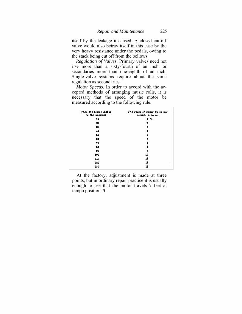
Repair and Maintenance 225
itself by the leakage it caused. A closed cut-off valve would also betray itself in this case by the very heavy resistance under the pedals, owing to the stack being cut off from the bellows.
Regulation of Valves. Primary valves need not rise more than a sixty-fourth of an inch, or secondaries more than one-eighth of an inch. Single-valve systems require about the same regulation as secondaries.
Motor Speeds. In order to accord with the ac-cepted methods of arranging music rolls, it is necessary that the speed of the motor be measured according to the following rule.
At the factory, adjustment is made at three
points, but in ordinary repair practice it is usually enough to see that the motor travels 7 feet at tempo position 70.
226 Piano Playing Mechanisms
Motor Fast. If the motor runs faster than it should the spring of the motor governor should be slightly slackened.
Motor Slow. In this case the spring of the gov-ernor may be tightened. In both the above cases the test roll may be used for measuring the speed. It is best to mark out on the roll the foot-intervals for ten feet or so, and then hold a watch on the travel at selected position, of the tempo dial.
Motor Races. If the motor runs too fast as soon as one begins to pedal energetically, this is a sign that the motor governor does not close sufficiently. The adjusting screw should be brought out a little. Do not touch the spring unless the motor races also on normal pumping.
Motor Drags. If the motor begins to slow down on energetic pedaling, the governor closes too much. Adjust by means of the screw, turing it inwards a little so that the governor shall close a little more. If the motor drags, however, on very slight pedaling, then the spring should be strengthened.
Motor Runs Irregularly. Sometimes a motor seems to hesitate, "gasp" and visibly "hitch" in its running, especially when carrying a heavy load, as at the end of a long roll. This indicates usually that the sliders are not seating correctly, which again is probably due to their warping or to some trouble on the face of the seat. Wooden slides may be sandpapered down flat, and so may the surface on which they seat. The latter may be treated with
Repair and Maintenance 227
powdered graphite well rubbed in and burnished by-rubbing with a steel rod, but one must never let grease or oil get mixed up with the graphite. If, however, the slides seem to seat well but the motor continues to run irregularly, one must first look to see if the slider valves are properly adjusted on their connecting rods. If there is any doubt as to this, disconnect each one in turn and carefully place it first at one and then at the other end of its travel, marking the position each time with a pencil on the seat. Then adjust each one on its connecting rod accordingly. Of course, there is always the possibility of a torn pneumatic cover also.
Motor Races Continually. In this case the speed valve, which is connected with the re-wind device, and is found in the tempo box, is for some reason being held open, or else the tempo valve does not seat properly. If there is a silencer button this may be operating the speed valve through a leak in its corresponding tube. Look especially for tube leaks in all pneumatic re-roll (re-wind) devices.
Dampers Always Lifted. Look for a leak in the tube which runs from the tracker or the button to the damper-lift pneumatic. If an automatic sustaining pedal device exists, as in most players, the leak may be in the shut-off lever in the spool box. Sometimes air gets in under the spring below the control button. In this case the spring should be strengthened, or perhaps it will be found that a new leather pad is needed over the opening to the air tube.
228 Piano Playing Mechanisms
Damper Works Slowly. The damper lift (sustaining pedal) pneumatic contains a great deal of power. If, when it is adjusted to operate quickly, it is usually noisy and extravagant, making a call on the power, which is felt at the pedals, and is noticeable in motor-driven players, this is because its valve has been regulated to have a long travel and the vent has been enlarged accordingly. If, on the other hand, the valve-travel is shortened and the bleed made smaller, the pneumatic will work silently and easily, but slowly. One can only hope to strike a happy compromise.
Soft Expression Unsatisfactory. Sometimes it is found that the player does not repeat well when the softening buttons are depressed. This is usually when the pneumatic stack is divided and an expression governor works on each half under control of a button. The governor springs should then be strengthened, or weakened if the soft expression is not soft enough. Similar considerations apply when the soft expression is worked through the agency of marginal ducts and perforations.
Bellows Troubles. These, fortunately, are not many. Flap valves sometimes begin to work badly, owing to the leather stretching or the boards warping. The springs of these valves may need strengthening, and a little talcum powder sprinkled over their seats will usually work wonders. Once in a very great while some dirt may get in and block open the inner flap-valve. In this case the bellows
Repair and Maintenance 229
must be opened up, as there is no other way of getting at the trouble.
Remedying Other Defects. Cracks in boards are best filled with shellac, but if they are very wide may be filled in with soft wood, over which is then glued a bit of bellows cloth.
Torn or cracked pneumatic cloth may be either patched or replaced. If the crack is too bad to be handled by cementing a little patch of new cloth over it, then the whole cloth should be taken off carefully. Usually it can be pulled off if one can get a start at one end; otherwise it must be cut off, but one should always try pulling first. Then, using the old cloth as a pattern, cut a piece of new cloth and re-glue. Before re-gluing always look to the hinge-cloth of the pneumatic and see if this is all right. Also see that the wood surfaces are clean and not too smooth. In re-gluing, use hot glue if possible, spread thin, and press the cloth on with a hot iron, but not one hot enough to burn it. Begin at the further end and work backwards towards the hinge. Use always the same kind of cloth as was first put on. There is never any difficulty in getting such cloth nowadays. A rubber-coated cotton material is now in general use which calipers from .005 to .0075-inch. Motor pneumatics are covered with a somewhat stronger cloth, calipering .008-inch to .015-inch.
Tom or cracked bellows cloth is treated in the same way as the lighter work described above. The
230 Piano Playing Mechanisms
cloths used today are strong rubberized twills and jeans and are extremely durable, lasting for many years. It is easy to put patches on these. One good way is to cut a circular piece of sheep-skin (as used for organs) large enough to allow a good inch all around the tear, and fasten it by applying glue around its edges only, leaving all its center loose and free.
Torn or cracked pouches must be replaced with kid or with zephyr leather. If the latter is used, the special directions as to gluing, issued by the manu-facturers, should be carefully followed. Pouches must be cut to fit, with generous allowances for mo-tion, and pressed onto the seats with a wooden block.
Special Troubles of Reproducing Pianos. The very carefully elaborated tests detailed in the va-rious books issued by the manufacturers of every make of reproducing piano will show how to look for all pneumatic defects, and it is only necessary here to make a few simple remarks on the subject.
First.—The reproducing piano is simply a player-piano provided with additional governors controlled by the music roll through marginal tracker ducts. The existence of these marginal ducts involves the necessity for the utmost nicety in registration of paper with tracker. Whenever a complaint is made, this point should first be seen to.
Second.—The pumping system has occasional de-fects of its own. The belt often gives some little
Repair and Maintenance 231
trouble by slipping, and so holding up the power supply. Commutators on motors may become corroded. Motors need lubrication. Carbons need replacing at long intervals. Otherwise, of course, all pump troubles are what one is likely to find in ordinary player bellows systems.
Third.—Dirt, dust, lack of lubrication on moving parts of metal, torn or mutilated music rolls, and imperfect understanding on the part of the owner as to the simple adjustments needed to start the instrument going, remove or insert the roll, etc., are just as likely, no more and no less, to cause reproducing piano trouble as to cause complaints in ordinary player-pianos.
Fourth.—Every adjustment, regulation and test required for every make of reproducing piano is carefully set forth by its makers in special booklets which, together with test rolls, are at the service of every qualified technician, without charge. To repeat these in the present book is neither desirable nor necessary.
(THE END)
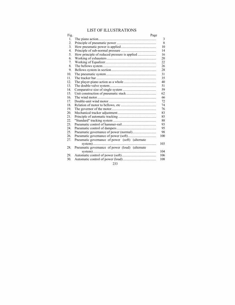
LIST OF ILLUSTRATIONS Fig. Page 1. The piano action.................................................................. 3 2. Principle of pneumatic power ............................................. 8 3. How pneumatic power is applied........................................ 10 4. Principle of sub-normal pressure ........................................ 14 5. How principle of reduced pressure is applied ..................... 16 6. Working of exhausters ........................................................ 20 7. Working of Equalizer.......................................................... 22 8. The bellows system............................................................. 26 9. Bellows system in section ................................................... 28
10. The pneumatic system......................................................... 31 11. The tracker bar .................................................................... 35 12. The player-piano action as a whole ..................................... 40 13. The double-valve system..................................................... 51 14. Comparative size of single system ...................................... 59 15. Unit construction of pneumatic stack .................................. 62 16. The wind motor ................................................................... 66 17. Double-unit wind motor ...................................................... 72 18. Relation of motor to bellows, etc ........................................ 74 19. The governor of the motor................................................... 76 20. Mechanical tracker adjustment............................................ 83 21. Principle of automatic tracking ........................................... 85 22. "Standard" tracking system ................................................. 88 23. Pneumatic control of hammer-rail....................................... 93 24. Pneumatic control of dampers ............................................. 95 25. Pneumatic governance of power (normal)........................... 98 26. Pneumatic governance of power (soft) ................................ 100 27. Pneumatic governance of power (soft) (alternate
system)........................................................................ 103 28. Pneumatic governance of power (loud) (alternate
system)........................................................................ 104 29. Automatic control of power (soft) ....................................... 106 30. Automatic control of power (loud)...................................... 108
233
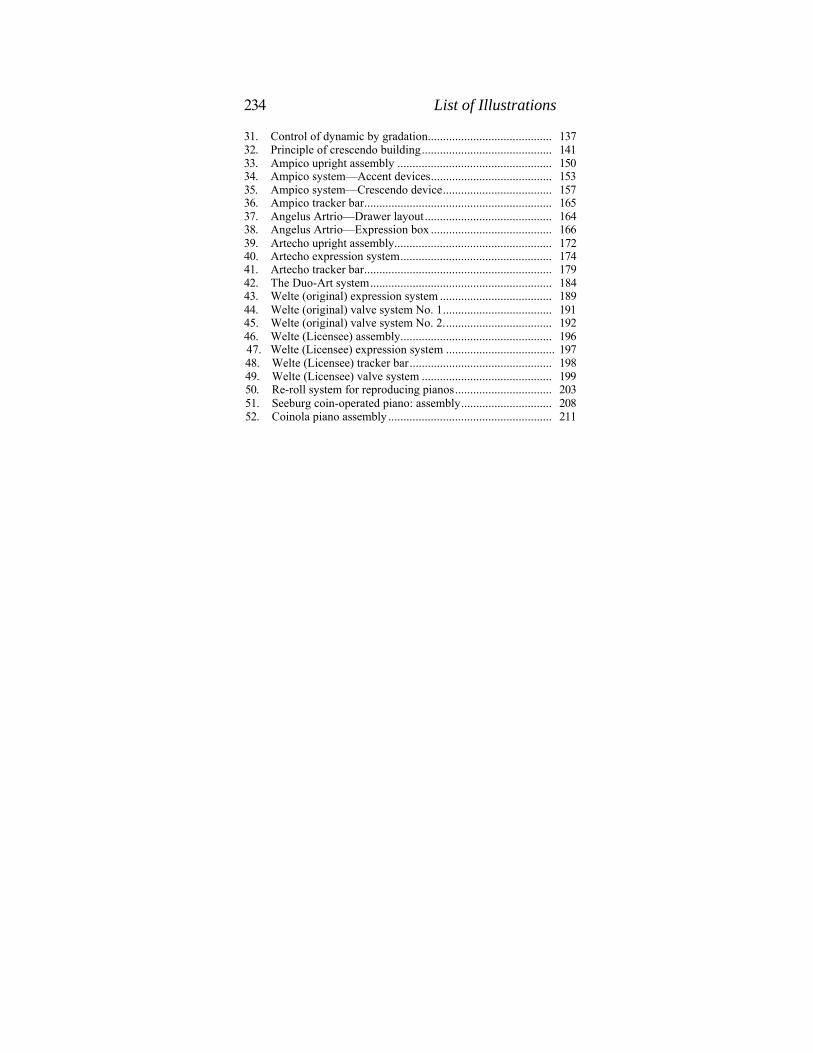
234 List of Illustrations
31. Control of dynamic by gradation......................................... 137 32. Principle of crescendo building........................................... 141 33. Ampico upright assembly ................................................... 150 34. Ampico system—Accent devices........................................ 153 35. Ampico system—Crescendo device.................................... 157 36. Ampico tracker bar.............................................................. 165 37. Angelus Artrio—Drawer layout.......................................... 164 38. Angelus Artrio—Expression box ........................................ 166 39. Artecho upright assembly.................................................... 172 40. Artecho expression system.................................................. 174 41. Artecho tracker bar.............................................................. 179 42. The Duo-Art system............................................................ 184 43. Welte (original) expression system ..................................... 189 44. Welte (original) valve system No. 1.................................... 191 45. Welte (original) valve system No. 2.................................... 192 46. Welte (Licensee) assembly.................................................. 196
47. Welte (Licensee) expression system .................................... 197 48. Welte (Licensee) tracker bar............................................... 198 49. Welte (Licensee) valve system ........................................... 199 50. Re-roll system for reproducing pianos................................ 203 51. Seeburg coin-operated piano: assembly.............................. 208 52. Coinola piano assembly ...................................................... 211
236 Index
Artecho—continued illustrated, 179 Valves, cancel, 178 crescendo - diminuendo,
175 governing, 173 illustrated, 174 intensity, 177 lock, 178 pianissimo, 177
B. Bellows, complete, 2 7
construction, 41 described, 23, 41 flap valve, 42 illustrated, 14, 15, 20, 22,
26 principle, 13 trouble in, 228 Bleed (See
under Vent) Bleed-Hole (See under Vent)
C. Canceling, 144
(Also see Ampico, etc.) Celco Reproducing Medium
(See Artecho) Chamber,
Reduced pressure, construction, 65 described, 30 primary, 54
secondary, 54 Climate, influence of, 211 Cloth, defects of, 229 Coin-operated, Player-piano,
accessories, 210 care, 214 Coinola, 210 early types, 129 essential features, 206 illustrated, 208, 211v motor, 207 music roll, 212
Coin-operated—continued pneumatic stack, 209 pumps, 208 re-roll, 208 tracker bar, 209, 211
Complaints, by owners, 216 ignorance as cause, 217
Crescendo, (See also Expression) building up, 141, 143 fast, 143 method, 140 pianistic effect, 139 slow, 143
D. Damper,
Lift, automatic, 96 defects, 227, 228 described, 94 illustrated, 95 pneumatic, 95 Design,
scientific, 111 Dimensions of pouches, 127
of pneumatics, 122 of valves, 125
Diminuendo, (See under Dynamic and Expression)
Double-Valve, System,
described, 54 why adopted, 52
Duo-Art— Assembly, diagrammed, 184
"Dynamics" (See Pneumatics below)
Expression System, accompaniment, 180 cut-off, 185 described, 181 diagrammed, 184 expression box, 182 hand control, 187 principle, 180 summarized, 187 "theme," 180 working of, 185
Index 237
Duo-Art—continued Pneumatics, accordion dynamics, 182 illustrated, 184 zero, 180, 183 Tracker bar, layout, 182
illustrated, 184 Valves, jack-knife, 182 knife-valve control, 181 primary, 185 secondary, 185 spill, 183 Dynamic (dynamics) In player-piano, Analysis, mechanical, 115
ultimate, 134 Automatic, principle described, 107 principle illustrated, 106 Control, 97 by gradation, 137 illustrated, 99, 100 Crescendo, 138 Diminuendo, 138 Index of, 133 Normal, level, 117 soft, 102 Problem, of automatic, 133 simple solution, 135 Steps, 136, 139
E. "Emptiness,"
an abstract idea, 27 Equalizer, In bellows system,
described, 23 dispensed with, 49 functions analyzed, 47 illustrated, 23, 27, 40 systems compared, 46 theories of, 43
Exhauster In bellows system,
described, 23, 41 illustrated, 22, 27, 40
Expression (See also under Dynamic) Control,
ultimate principle, 149 Crescendo, 138 Diminuendo, 138 Elements,
mechanical, 132 Index, 134
P. Flap-valve (See under Bel-
lows System) Foot-treadle
(See under Treadle) G.
Gauge, water, 118 Gradation (See under Dynamic, Step)
H. Hammer, of piano, velocity, 5 Hammer-rail,
control, 91 illustrated, 93 pneumatic, 92
Hygrometer, use of, 219 L.
Leakage, 222 Leather, for pouches, 60
torn, 230 Loud pedal
(See under Damper) Lumber,
for pneumatics, 64 for stacks, 65
M. Motor
See also under Re-roll) Electric, troubles of, 231 Wind, delicacy of, 68 drags, 226
238 Index
Motor—continued fast, 226 functions of, 69 illustrated, 67, 72 irregular, 226 operations of, 70 plays on re-roll, 224 races, 226 slow, 226 speed, 75, 225 turning engine, 67
Music, mechanical analysis of, 17
Music roll, chucks, 73 coin-operated, 212 driving mechanism, 65 principle, 36 speed, 67 spool, 73 is a traveling valve, 34
Organ, Pipes,
in coin-operated piano, 210 tuning of,
212 P.
Piano (See under Piano Action, Player Action, Piano-Playing Mechanisms, Pitch, Reproducing Piano, etc.)
Piano action, illustrated, 3, 40 described, 2
Piano-playing mechanism, definition, 1 power requirements, 115
Pitch, transposition of, 82
Player action, application to piano-play-
mg, 18 definitions of, 1 does not play, 224 enemies of, 218
Player action—continued illustrated as a whole, 40 rudimentory form of, 17
Player-pianist, definition, 38
Pneumatic, Expression, automatic, illustrated, 106,
108 principle, 107 illustrated, 9,100 9manual, 99 master, 140 operating method, 137
Playing, ciphering, 223 construction, 64 dimensions, 120 function, 11
Pneumatic stack, coin-operated, 208 defined, 31 described, 50 illustrated, 40, 51 no power, 224
Pouch, of valve, construction, 60
function, 32 illustrated, 31 Power, ' (See
also under Dynamic) Automatic, defined, 129
plant, 130 Lack of, 224 Maximum, 117 Minimum, 116 Pressure, atmospheric, 7
maximum, 117 measurement, 117 minimum, 116 opposed, 115 reduced, 11 sub-normal, 25 super-normal, 25 working, 12
Pump, See also under Bellows) defined, 130
Index 239
Pump (See also Exhauster) when used, 130 suction, 221 Pumper (See
under Pump) R.
Recording, of phrasing, 133 of dynamic, 133 of pedal work, 134
Repairs, (See p. 216-231, and under
individual classifications in this index)
Repetition, sluggish, 221 Reproducer (See under Re-
producing Piano) Reproducing Piano,
(See also under Ampico, Angelus - Artrio, Celco, Duo-Art, Welte - Mignon, etc.) basic principles, 135 re-roll system, 202 technicians and, 149 troubles of, 230
Re-roll, automatic, 202 illustrated, 74, 76, 203 lever, 73 valve, 75
Reservoir, (See under Equalizer)
Rewind (See under Re-roll) Rewinding,
(See under Re-roll) Roll (See under Music Roll)
S. Shellac, use of, 65, 223 Silencer, described, 109 Single-valve,
(See under Valve) Soft pedal,
(See under Hammer-rail) Spool, take-up, 73 Springs, bellows, 42 Sta£k, (See under Pneumatic stack)
Step, dynamic, 136 T. Technicians, manuals for, 147 Temperature, 219 Tempo,
box, described, 76 box, illustrated, 74, 76 control, 77 defined, 78 governor, 78 slot, 77 valve, 77
Testing, rolls for, 148, 221
"Touch," how indicated, 133
mechanical equivalent of, 135 Tracker bar,
coin-operated, 210 functions, 35 illustrated, 35
Tracking, automatic, 85 defects in, 84 devices, 81 "Standard" system, 86
Treadle, illustrated, 40 Tuning, coin-operated, 213
frequency of, 220 need of, 220 rules for, 218
V. "Vacuum,"
(See also under Pressure "high," 12 partial, 11 Valve,
action-cut-off, 28 dimensions, 126 disk, 32 do not seat, 223 expression, 144 functions analyzed, 123 jack-knife, 101, 145 primary, 54 regulation of, 225
240 Index
Valve—continued secondary, 54
Construction, primary, 61 secondary, 61 single, 62 unit, 62
Systems, compared, 125 double, described, 50 54 , double, illustrated, 51 single, described, 30 single, illustrated, 31, 40
Vent, construction, 63 function, 33 illustrated, 31 in double system, 55
W. Welte (Licensee)—
Accessories, illustrated, 196 Assembly,
illustrated, 196 Expression system,
crescendo, 196,198 cut-off, 201 described, 195 forzando, 198, 199 hand control, 201 illustrated, 197
Pneumatics, expression, 196 governor, 197 illustrated, 197, 199 stop, 195, 199
Pneumatics—continued Tracker bar,
illustrated, 198 layout, 201
Valves, control, 198 crescendo, 198 double-function, 198 forzando, 199 illustrated, 199 single-function, 199 Welte (Original)—
Accessories, 194 Expression system,
crescendo, 190, 193 described, 189 expression pneumatic,
191 forzando, 190, 193 governing bellows, 190 hand control, 193 units, 190 valves, 190 valve block, 193
Pneumatics, expression, 191 mezzo-forte, 191 operation of, 193 volume-control, 195
Re-roll, 195 Tracker bar, layout, 190
Valves, block, 193 controlling, 190 illustrated, 191, 192 spill, 189 "Wind motor,"
(See under Motor)