piasecki aircraft corporation technical … … · 50-x-6 tm-dgsc-7310-193 p/n 995-2 fsn...
TRANSCRIPT

50-X-6 TM-DGSC-7310-193
P/N 995-2 FSN 7310-905-6212
T.O. 13B1-4-3
PROPRIETARY INFORMATION: The use and disclosure of the technical data on this sheet is subject to the restrictions stated in the legend on the cover page of this document, which legend must be reproduced on any reproduction of any of this technical data. \\Piac2\piac data\Projects\Active\50 - Corporate Assets\50-X-006_Oven\Technical Manuals\CURRENT TECHNICAL MANUAL\50-X-006 TECHNICAL MANUAL OVEN 995-2 REV B.doc
PIASECKI AIRCRAFT CORPORATION
TECHNICAL MANUAL OVERHAUL WITH PARTS BREAKDOWN
AIRCRAFT OVEN - P/N 995-2
50-X-006 Rev: B
Title/Subject: Technical Manual for Aircraft Oven P/N 995-2 FSN: 7310-905-6212 T.O.: 13B1-4-3 Date: 23 February 2011 (Revised) Written By: Piasecki Aircraft Corporation PO Box 360 West Second Street Essington, PA 19029-0360 (610) 521-5700

50-X-6 TM-DGSC-7310-193
P/N 995-2 FSN 7310-905-6212
T.O. 13B1-4-3
PROPRIETARY INFORMATION: The use and disclosure of the technical data on this sheet is subject to the restrictions stated in the legend on the cover page of this document, which legend must be reproduced on any reproduction of any of this technical data.
1
ISSUED: 20 MARCH 1969 REVISED: 23 February 2011
SECTION I
OVERHAUL INSTRUCTIONS
TABLE OF LEADING PARTICULARS
TM-DGSC-7310-193
TECHNICAL MANUAL OVERHAUL WITH PARTS BREAKDOWN
AIRCRAFT OVEN PIASECKI AIRCRAFT CORPORATION
Phone 610-521-5700 Fax 610-521-5935
E-mail: [email protected]
P/N 995-2
FSN 7310-905-6212 T.O. 13B1-4-3
Each transmittal of this document outside the agencies of the U.S. Government must have prior approval of
Defense General Supply Center, ATTN: DGSC-P.
Temperature Range 140° to 400 °F Fusing 10 amperes, each phase Timing Range 0 to 60 min. Working Chamber 13 x 9.625 x 7.375 inches Thermostat Cut-Off 425°F+ Shelves 7 Input 200 volts, 400 cycles, 3 phase AC Dimensions 19.25 x 18.50 x 10.250 inches
Power 2,400 watts Weight 30 pounds

50-X-6 TM-DGSC-7310-193
P/N 995-2 FSN 7310-905-6212
T.O. 13B1-4-3
PROPRIETARY INFORMATION: The use and disclosure of the technical data on this sheet is subject to the restrictions stated in the legend on the cover page of this document, which legend must be reproduced on any reproduction of any of this technical data.
2
REVISION STATUS SHEET
Date Revision Number Description Initiated By 14 October 2004 FzWP 10 March 2008 FzWP
7 Jul 2009 Rev A Power changed from 2,000 watts, Parts list
Modified MPM
23 Feb 2011 Rev B Corrected typos on page 10 AJR

50-X-6 TM-DGSC-7310-193
P/N 995-2 FSN 7310-905-6212
T.O. 13B1-4-3
PROPRIETARY INFORMATION: The use and disclosure of the technical data on this sheet is subject to the restrictions stated in the legend on the cover page of this document, which legend must be reproduced on any reproduction of any of this technical data.
3
1. SPECIAL TOOLS. None. 2. DISASSEMBLY. Disassemble in the
same order as the key items assigned to the exploded view illustrations, figures 1 to 4. Before removing wiring from any electrical items, note connections in accordance with schematic wiring diagram in figure 5 and tag wiring connections before removing. The electrical items are identified by name and vendor part number. The procedures given below are only for those items in the Field Repair and Major Overhaul Kits whose replacement may not be entirely obvious from the illustrations.
a) Oven Door (5, Figure 1).
1) Close oven door (5) making sure latch and keeper are engaged.
2) Drive out hinge pin (3) until spring (4) is released. Remove spring and complete driving out hinge pin.
3) Remove hinge section (2) from the door by taking out five screws.
4) Take off door latch (6) by removing four screws.
5) Remove four screws from outer case (7) releasing remaining assembled portion of the door. Separate inner plug (8), insulation (9), gasket (10) and wood frame (11) by taking out four screws from inner plug (8).
b) Hinge (2, Figure 1).
1) Perform steps 1 to 3 of paragraph 2a.
2) Remove hinge section (3) on outer case (1).
c) Timer (9, Figure 2).
1) Remove bottom cover (3) by taking out six screws holding the bottom cover.
2) Note two wire leads (figure 5) on back of timer (9, figure 2), and
remove leads by unfastening screws holding terminals in place.
3) Remove timer (9) by unfastening its securing ring and push timer out through the front of the outer case (1).
d) Limitstat (19, Figure 2).
1) Perform step 1 of paragraph 2.c 2) Note and mark two wire leads
(figure 5) connecting to terminal block (20, figure 2), and remove leads by unfastening screws holding terminals in place.
3) Remove cover (17) by unfastening four screws, and remove limitstat together with its clamp (18) from the bottom of the outer case (1).
4) Remove clamp (18) from item 19 by taking out two screws.
e) Heater Assembly (3, Figure 3).
1) Slide out the seven shelves (13, figure 1).
2) Remove two locknuts (4, figure 3) and using even pressure, without any twisting motion, pull out heater assembly (3).
f) Thermostat (4, Figure2).
1. Remove heater assembly in accordance with paragraph 2e.
2. Remove outer covers as given in step 1 of paragraph 2c and 2h.
3. Unfasten the two wires going to the thermostat (8). Remove the screws holding the bulb in place on the surface of the inner chamber (12, figure 4) and free bulb from chamber by gently pulling downwards through porcelain bushing (21, figure 2).
4. Unfasten two setscrews in knob (5) and free knob from shaft.
5. Unthread stop (6) and screw, releasing dial (7) and thermostat (8).

50-X-6 TM-DGSC-7310-193
P/N 995-2 FSN 7310-905-6212
T.O. 13B1-4-3
PROPRIETARY INFORMATION: The use and disclosure of the technical data on this sheet is subject to the restrictions stated in the legend on the cover page of this document, which legend must be reproduced on any reproduction of any of this technical data.
4
g) Fan Impeller Blade (6, Figure 3).
1. Perform steps 1 and 2 paragraph 2e.
2. Remove fan locknut (5), and pull fan impeller blade (6) from shaft of motor (7).
h) Rubber Bushing (13, Figure 3).
1. Remove outer case cover (2) by unfastening four screws.
2. Remove connector cover (10) from holder (12) by unfastening four screws.
3. Note four connections (figure 5) on connector (11, figure 3). Unsolder connections.
4. Pull wires previously unfastened in step 3, above through rubber bushing (13). Pry out item 13.
i) Relay (14, Figure 3).
1. Remove outer case cover (2) by taking out four screws.
2. Note and mark eleven wire leads (figure 5) connecting to terminal block (9, figure 3), and remove leads by unfastening screws holding terminals in place.
3. Take off relay (14) by unfastening four screws.
j) Heater Jack Connector (6, Figure 4)
1. Performs steps 1 and 2 of paragraph 2e and step 1 of paragraph 2i.
2. Disconnect wires from two contacts (15, figure 3), by unfastening nuts holding two terminals in place on the connector (6, figure 4).
3. Unfasten two screws on connector (6) and remove from inner chamber (12) by pushing straight out from the chamber side.
4. Remove each contact referred to in step 2 above by unfastening a screw and nut.
NOTE
Many repair parts for equipment covered in this publication are provided in the form of kits. See Section II, Group Assembly Parts List, for details. Presence of a new part in the applicable kit eliminates the necessity of cleaning, inspecting, or reworking the equivalent used part removed from the assembly being repaired; therefore, such instructions have been omitted from this manual. Activities shall replace all parts (regardless of condition) which are removed in the process of disassembly with all like parts furnished in the kit. If an installed part is not defective, it need not be removed solely for the purpose of replacement by a corresponding kitted part. Residue from kits and removed parts in this category shall be administratively condemned. The instructions which follow cover removed parts not supplied in kits and kitted parts (if any) which require cleaning, inspecting, or testing prior to installation. 3. CLEANING. Pull out shelves and
remove heater assembly (paragraph 2e). Use damp cloth to wipe interior and exterior surfaces of the oven.

50-X-6 TM-DGSC-7310-193
P/N 995-2 FSN 7310-905-6212
T.O. 13B1-4-3
PROPRIETARY INFORMATION: The use and disclosure of the technical data on this sheet is subject to the restrictions stated in the legend on the cover page of this document, which legend must be reproduced on any reproduction of any of this technical data.
5
4. INSPECTION. a) Inspect all surfaces for dents,
breaks, and scratches. b) Inspect door and securing hardware
for improper action or fit. c) Inspect door and frame for signs of
charring. d) Inspect latch handle from missing or
cracked heat insulating cover. e) Inspect all mechanical parts for
security, signs of corrosion or excessive wear.
f) Inspect all electrical parts for signs of overheating, arcing, and poor connections, or chafed insulation of wiring.
g) Inspect heater assembly contacts for improper alignment or poor condition.
h) Inspect heater jack connector for cracks; its contacts for poor action or sign of arcing, etc., and poor electrical surfaces.
i) Inspect relay armature for binding or sticking; its contacts for signs of arcing, dirt, grease, or other poor electrical surfaces.
j) Inspect fan impeller for binding action such as due to distorted blades.
k) Inspect instruction plate for security.
5. REPAIR AND REPLACEMENT
a) Check continuity of the three fuses and replace if necessary.
b) Replace lamp. If new lamp does not light, check continuity. If normal, check pilot light resistor for 1,250 ohms.
c) If relay contacts are scored, or show signs of poor electrical contact, or if relay action is not proper, replace relay in its entirety.
d) If oven overheats or does not heat check fuses, thermostat, timer, limitstat, relay, and heaters for open contacts or open circuits. After repair and replacement of parts, test
in accordance with procedure in paragraph 8.
6. LUBRICATION. None. 7. REASSEMBLY. Reassembly is the
reverse of disassembly. The following procedures refer to special precautions that must be taken with certain items when reassembling them into the oven.
a) Thermostat (4, Figure 2). Whenever the knob (5), dial (7), or thermostat (8) is removed or replaced, perform the following procedure to insure normal temperature operation of the oven.
1. Reassemble following the reverse of the procedure given in paragraph 2f; however, do not replace knob; make sure shaft on thermostat (8) is completely turned to the counterclockwise position.
2. Refer to and follow the procedure given in paragraph 8 for measuring oven temperature. After a suitable temperature indicator has been connected, turn on power. Adjust shaft by turning (by increments) in the clockwise direction until a reading of 400°F is noted. Allow time for this reading to stabilize before proceeding with the next step.
3. Put knob (5) on shaft of thermostat (8), taking care not to disturb the shaft setting. Make sure that the knob pointer is flush against the right-hand side of stop (6). Secure knob by fastening setscrews.
4. Check temperature after five minutes and repeat steps 2 and 3 if a disturbed setting is noted.
CAUTION

50-X-6 TM-DGSC-7310-193
P/N 995-2 FSN 7310-905-6212
T.O. 13B1-4-3
PROPRIETARY INFORMATION: The use and disclosure of the technical data on this sheet is subject to the restrictions stated in the legend on the cover page of this document, which legend must be reproduced on any reproduction of any of this technical data.
6
b. Rectifier (18, Figure 3). Observe
correct polarity connection whenever rectifier is to be replaced.
Rectifiers are liable to damage whenever subjected to excess heat. Make sure that a pair of long-nose pliers is held against terminal wire of a rectifier before applying heat during any soldering operations.
8. TEST PROCEDURE
Always wear heat resistant gloves or use insulated pad when handling hot items, or when working on oven during operation.
a) Place a 0° to 500°F range meter with thermocouple inside over. The thermocouple is connected to a suitable thermocouple indicating meter (range 0° - 500°F) in conjunction with a timing device to indicate acceptable “come up” time.
b) Set timer to HOLD position; the thermostat to “140”.
c) Turn on oven. Check that the temperature reaches approximately 140°F.
d) After completing the above step, set the thermostat to “400”. Check that the temperature reaches 400°F.
e) Set timer to five minutes and check that timer turns heat off when it reaches zero.
CAUTION
WARNING

50-X-6 TM-DGSC-7310-193
P/N 995-2 FSN 7310-905-6212
T.O. 13B1-4-3
PROPRIETARY INFORMATION: The use and disclosure of the technical data on this sheet is subject to the restrictions stated in the legend on the cover page of this document, which legend must be reproduced on any reproduction of any of this technical data.
7
SECTION II
GROUP ASSEMBLY PARTS LIST 9. GENERAL.
Following is the List of all parts contained in Piasecki Aircraft Oven (FSN 7310-905-6212). Items marked with either “ * “ or “ ** “ are included in the Major Overhaul Repair Kit. Only those items marked with “ ** “ are included in the Field Repair Kit. Standard screws used in the Major Overhaul Repair Kit or Field Repair Kit are supplied with the corresponding kit.
FIG & INDEX
NUMBER PART
NUMBER 1 2 3 4 DESCRIPTION
UNITS PER
ASSY SOURCE CODE
RECOV
CODE 1- 995-2 Piasecki Aircraft Oven………………………
FSN 7310-905-6212 1
-1 9951 . Case, Outer 1 -2* 99519 . Hinge Section 2 KD -3 N/A . . Pin 1 -4 99520 . . Spring 1 KD -5 99511 . Door 1
-6** 99517 . . Latch 1 KFD -7 99512 . . Case, Outer 1 -8 99516 . . Plug, Inner 1 -9 99513-1 . . Insulation 1
-10** 99515 . . Gasket, Silicone 1 KFD -11* 99514 . . Frame, Wood 1 KD -12 99573-1 . . Plate, Instruction 1
-13** 99523 . Shelf 7 KFD -14** 99518-1 . Keeper 1 KFD
1* 99574 . Misc. Hardware Set 1 KFD 1 99590 . Kit, Repair-Field
(FSN 7310-777-4533) 1 KF
1 99591 . Kit, Repair-Major Overhaul (FSN 7310-777-4534)
1 KD
2- 995-2 Piasecki Aircraft Oven
FSN 7310-905-6212 Ref
-1 9951 . Case, Outer Ref -2 9958 . . Skid 2 -3 99957-1 . . Cover, Bottom 1
-4** 99543-1 . Thermostat Assembly… 1 KF -5* 99546 . . Knob 1 KD -6 99547 . . Stop 1 KD -7* 99545 . . Dial 1 KD -8 99544 . . Thermostat 1 KD
N/A . . . Bulb, Thermostat 1

50-X-6 TM-DGSC-7310-193
P/N 995-2 FSN 7310-905-6212
T.O. 13B1-4-3
PROPRIETARY INFORMATION: The use and disclosure of the technical data on this sheet is subject to the restrictions stated in the legend on the cover page of this document, which legend must be reproduced on any reproduction of any of this technical data.
8
Figure 1 Piasecki Aircraft Oven

50-X-6 TM-DGSC-7310-193
P/N 995-2 FSN 7310-905-6212
T.O. 13B1-4-3
PROPRIETARY INFORMATION: The use and disclosure of the technical data on this sheet is subject to the restrictions stated in the legend on the cover page of this document, which legend must be reproduced on any reproduction of any of this technical data.
9
Figure 2 Piasecki Aircraft Oven, Controls Section

50-X-6 TM-DGSC-7310-193
P/N 995-2 FSN 7310-905-6212
T.O. 13B1-4-3
PROPRIETARY INFORMATION: The use and disclosure of the technical data on this sheet is subject to the restrictions stated in the legend on the cover page of this document, which legend must be reproduced on any reproduction of any of this technical data.
10
FIG & INDEX
NUMBER PART
NUMBER 1 2 3 4 DESCRIPTION
UNITS PER
ASSY SOURCE
CODE RECOV CODE
2-9** 99542 . Timer………………………………………… 1 KD -10 99536-1 . Pilot Light Assembly……………………….. 1
-11** 99539 . . Lens……………………………………… 1 KFD -12** 99538 . . Lamp 6240-459-5367………………….. 1 KFD -13 99537 . . Body…………………………………….. 1 -14 99540-1 . Fuse Holder and Cap Assembly, Body…. 3
-15** 99541 . . Fuse…………………………………….. 3 KFD -16 99535-1 . Switch, Toggle……………………………… 1 -17 99582 . Plate, Limitstat 1
-18** 99583 . Limitstat Assembly 1 -19 99548-1 . Limitstat……………………………………… 1 KFD -20 99558-1 . Block, Terminal…………………………….. 1 -21 99534-1 . Bushing, Porcelain…………………………. 1
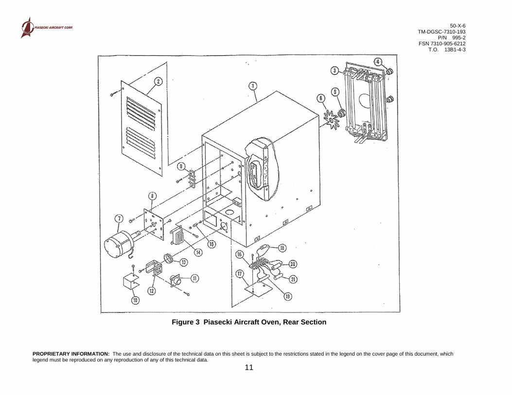
3- 995-2 Piasecki Aircraft Oven FSN 7310-905-6212 Ref
-1 9951 . Case, Outer Ref -2 99575 . . Cover, Outer Case…………………….. 1
-3** 99559-3 . Heater Assembly (see Figure 4, item 1)…. 1 KFD -4** 99563-1 . . Locknut………………………………….. 2 -5* 99527 . . Locknut………………………………….. 1 KFD -6* 99526-1 . . Fan Impeller Blade (see Figure 4)..….. 1 KFD -7* 99524-1 . . Motor…………………………………….. 1 -8 99525 . . Plate, Mounting 1 -9 99557-1 . Block, Terminal…………………………….. 1 -10 99532 . . Connector Cover 1 -11 99530-2 . . Connector, 4-Pin AN…………………… 1 -12 99531-1 . . Holder, Connector……………………… 1 -13 99533-1 . Bushing, Rubber…………………………… 1 KD -14* 99551-1 . Relay………………………………………… 1 KD -15 99529-1 . Contact, Connector Jack………………….. 4 KD -16 99556-1 . . . Block, Terminal……………………… 1 -17 N/A . . . Block Strip, Terminal……………….. 1 -18* 99553-1 . . . Rectifier, Relay……………………… 1 KD -19* 99552-1 . . . Resistor, Pilot Light…………………. 1 KFD -20* 99554-1 . . . Capacitor, Relay…………………….. 1 KD -21* 99555-1 . . . Resistor, Relay………………………. 1 KD
4- 995-2 Piasecki Aircraft Oven FSN 7310-905-6212 Ref
-1 99559-3 . Heater Assembly…………………………… Ref KFD -2 99560-1 . . Cover…………………………………….. 1 -3 99561-1 . . Jack, Male………………………………. 4 -4 99562 . . Element Assembly 6 99580-1 . . . Holding Block, Heater Element 2 99580-2 .
. . Holding Block, Heater Element 2
99581-2 .
. . Conductor Strip 1 -5 99522 . Shelf, Support Assembly 2 KFD -6 99528-1 . Connector, Female………………………… 4 KD -7 99521-1 . Chain, Door Retainer………………………. 1 KD
50-X-6 TM-DGSC-7310-193
P/N 995-2 FSN 7310-905-6212
T.O. 13B1-4-3
PROPRIETARY INFORMATION: The use and disclosure of the technical data on this sheet is subject to the restrictions stated in the legend on the cover page of this document, which legend must be reproduced on any reproduction of any of this technical data.
11
Figure 3 Piasecki Aircraft Oven, Rear Section

50-X-6 TM-DGSC-7310-193
P/N 995-2 FSN 7310-905-6212
T.O. 13B1-4-3
PROPRIETARY INFORMATION: The use and disclosure of the technical data on this sheet is subject to the restrictions stated in the legend on the cover page of this document, which legend must be reproduced on any reproduction of any of this technical data.
12
Figure 4 Piasecki Aircraft Oven, Heating Section

50-X-6 TM-DGSC-7310-193
P/N 995-2 FSN 7310-905-6212
T.O. 13B1-4-3
PROPRIETARY INFORMATION: The use and disclosure of the technical data on this sheet is subject to the restrictions stated in the legend on the cover page of this document, which legend must be reproduced on any reproduction of any of this technical data.
13
Figure 5 Piasecki Aircraft Oven Wiring Harness

50-X-6 TM-DGSC-7310-193
P/N 995-2 FSN 7310-905-6212
T.O. 13B1-4-3
PROPRIETARY INFORMATION: The use and disclosure of the technical data on this sheet is subject to the restrictions stated in the legend on the cover page of this document, which legend must be reproduced on any reproduction of any of this technical data.
14
FIG & INDEX
NUMBER PART
NUMBER 1 2 3 4 DESCRIPTION
UNITS PER
ASSY SOURCE
CODE RECOV CODE
4-8 9954 . Back, Inner Case 1 -9 99576 . Support, Chamber Back Motor…………… 1 -10 9955-1 . Cover, Inner Case…………………………. 1 -11 9953-1 . Installation………………………………….. 1 -12 9952 . Chamber, Inner 1 -13 9956 . . Frame, Wood 1 -14 99510-1 . . Guide Pin, Heater Assembly………… 1 KD -15 9959-1 . . Stud, Heater Assembly………………. 2
5- 99572-1 Piasecki Aircraft Oven Wiring Harness…… 1
-1* 99566* . Terminal #6 Stud 22 – 16 AWG 15 KD -2* 99567* . Terminal #8 Stud 22 – 16 AWG 7 KD
-4* 99569 . Terminal #6 Stud 18 -14 AWG 6 KD -5* 99570 . Terminal #8 Stud 18 -14 AWG 4 KD
-7* 99564 . Wire, Main Leads, 21 feet 1 KD -8* 99565 . Wire, Control Leads, 17 feet 1 KD

50-X-6 TM-DGSC-7310-193
P/N 995-2 FSN 7310-905-6212
T.O. 13B1-4-3
PROPRIETARY INFORMATION: The use and disclosure of the technical data on this sheet is subject to the restrictions stated in the legend on the cover page of this document, which legend must be reproduced on any reproduction of any of this technical data. \\Piac2\piac data\Projects\Active\50 - Corporate Assets\50-X-006_Oven\Technical Manuals\CURRENT TECHNICAL MANUAL\50-X-006 TECHNICAL MANUAL OVEN 995-2 REV B.doc
15
Major Overhaul Kit Parts List Part# Description Qty 99514 Frame, Wood, Door 1 99515 Gasket, Silicone Rubber 1 99517 Latch, Door 1 99518 Keeper, Door 1 99519 Hinge w/Pin 1 99523 Shelves 7 99526-1 Fan, Impeller Blade 1 99527 Locknut, Fan 1 99538 Lamp, Pilot Light 1 99539 Lens Pilot Light 1 99541 Fuses, 10 amps 3 99542 Timer 1 99543-1 Thermostat, Assy 1 99546 Knob 1 99545 Dial 1 99583 Limistat Assy 1 99552-1 Resistor, Pilot Light 1 99553-1 Rectifier, Relay 1 99554-1 Capacitor, Relay 1 99555-1 Resistor, Relay 1 99563-1 Locknuts, Heater 2 99564 Wire, Main Leads 21 ft. 99565 Wire, Control Leads 17 ft. 99566 Terminal #6 Stud 22-16 AWG 15
99567 Terminal #8 Stud 22-16 AWG 7
99569 Terminal #6 Stud 18-14 AWG 6
99570 Terminal #8 Stud 18-14 AWG 4 99574 99559-3
Misc. Hardware Set 1 Heater Assy 1
Field Repair Kit Parts List
Part# Description Qty 99515 Gasket, Silicone Rubber 1 99517 Latch, Door 1 99518 Keeper, Door 1 99523 Shelves 7 99538 Lamp, Pilot Light 1 99539 Lens, Pilot Light 1 99541 Fuses, 10 amps 3 99542 Timer 1 99543-1 Thermostat, Assy 1 99583 Limistat Assy 1 99559-3 Heater, Assy 1 99563-1 Locknuts, Heater 2