pic controller assembly manual rev4b updated
TRANSCRIPT

8/3/2019 PIC Controller Assembly Manual Rev4b Updated
http://slidepdf.com/reader/full/pic-controller-assembly-manual-rev4b-updated 1/13
Word ClockPIC Controller PCBConstruction Notes
A fun clock to build
Rev4b (updated)Doug Jackson
VK1ZDJ
Jan 2011

8/3/2019 PIC Controller Assembly Manual Rev4b Updated
http://slidepdf.com/reader/full/pic-controller-assembly-manual-rev4b-updated 2/13
Licence
The Word Clock Design, PCB layout, Manual, and Firmware is Copyright 2009-2011, byDouglas Jackson, VK1ZDJ.
This Design, PCB layout, Manual and Firmware is licenced under the TAPR Open
Hardware Licence (Non-Commercial). www.tapr.org/NCL.
Permission is granted for anybody to:
• Modify the documentation and make products based upon it, provided you do notmake more than ten units in any twelve month period.
• Use the products for any legal purpose without limitation.
• Distribute unmodified documentation, but you must include the complete packageas you received it.
• Distribute only on a non-profit basis, charging no more than the actual cost of parts,
assembly, and shipping.• Distribute products you make to third parties, if you either include the
documentation on which the product is based, or make it available without chargefor at least three years to anyone who requests it.
• Distribute modified documentation or products based on it, if you license your modifications under the OHL.
CAUTION
Welcome
Thanks for deciding to make this great little clock project. You will find that this simpleclock will be a centre piece for many discussions into the future, as well as providing agreat way to tell the time.
Because there are so many ways to construct the clock, I have broken assembly down intovarious documents – this document details the construction of the microchip PIC Controller board.
You will find that construction of this clock is very simple. If you are methodical with your
construction practices, and careful with you soldering, you will find that the clock almostassembles itself.
CAUTION
This project is designed to run of either 9V AC or 12V DC
IT IS NOT DESIGNED FOR DIRECT MAINSCONNECTION
Any attempt to connect the device to line mains (without atransformer) will cause the immediate destruction of the
project, and present a serious electrocution hazard.
8/3/2019 PIC Controller Assembly Manual Rev4b Updated
http://slidepdf.com/reader/full/pic-controller-assembly-manual-rev4b-updated 3/13
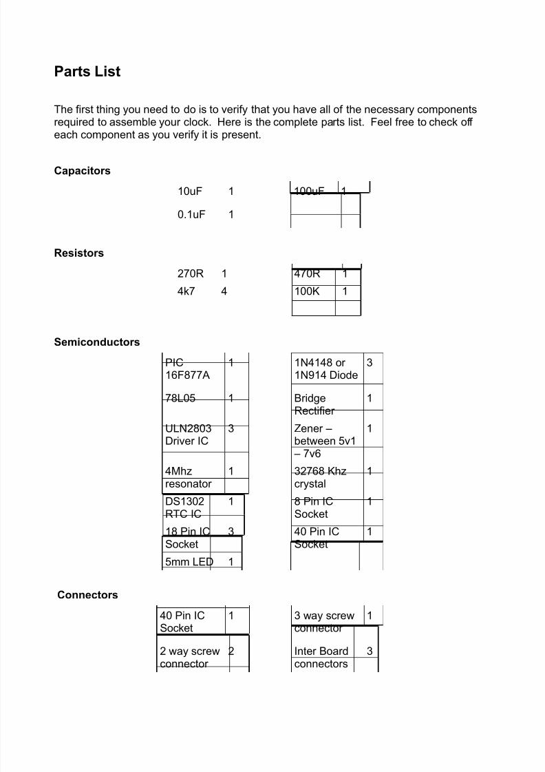
Parts List
The first thing you need to do is to verify that you have all of the necessary componentsrequired to assemble your clock. Here is the complete parts list. Feel free to check off
each component as you verify it is present.
Capacitors
10uF 1 100uF 1
0.1uF 1
Resistors
270R 1 470R 1
4k7 4 100K 1
Semiconductors
PIC16F877A
1 1N4148 or 1N914 Diode
3
78L05 1 BridgeRectifier
1
ULN2803Driver IC
3 Zener –between 5v1 – 7v6
1
4Mhzresonator
1 32768 Khzcrystal
1
DS1302RTC IC
1 8 Pin ICSocket
1
18 Pin IC
Socket
3 40 Pin IC
Socket
1
5mm LED 1
Connectors
40 Pin ICSocket
1 3 way screwconnector
1
2 way screwconnector
2 Inter Boardconnectors
3

8/3/2019 PIC Controller Assembly Manual Rev4b Updated
http://slidepdf.com/reader/full/pic-controller-assembly-manual-rev4b-updated 4/13
Component Layout
Use the following diagram to assist you in locating components on the PIC Controller PCB:
9V AC or
12V DC
Input
Optional
Battery
Backup
Forward
Time set
Backwards
-
+

8/3/2019 PIC Controller Assembly Manual Rev4b Updated
http://slidepdf.com/reader/full/pic-controller-assembly-manual-rev4b-updated 5/13
Construction
Assembling the controller board is fairly simple. Start by examining the copper side of thePCB for any manufacturing defects – I check each board before it is sent, but a second
check never goes astray.
Make sure that all tracks are complete, and not shorted to adjoining tracks. If there areany small shorts, remove them gently using a sharp blade.
You may find that the protective coating that has been applied to the hand made PCB (toprevent oxidation) requires additional time to allow a proper solder bond. This is normal.
Start assembly by installing the jumpers as per the below photo.

8/3/2019 PIC Controller Assembly Manual Rev4b Updated
http://slidepdf.com/reader/full/pic-controller-assembly-manual-rev4b-updated 6/13
The next step is to insert and solder the IC sockets and resistors.
8/3/2019 PIC Controller Assembly Manual Rev4b Updated
http://slidepdf.com/reader/full/pic-controller-assembly-manual-rev4b-updated 7/13
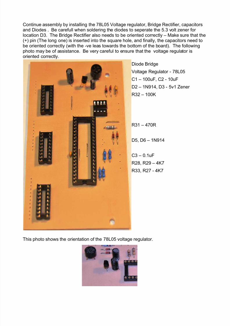
Continue assembly by installing the 78L05 Voltage regulator, Bridge Rectifier, capacitorsand Diodes . Be carefull when soldering the diodes to seperate the 5.3 volt zener for location D3. The Bridge Rectifier also needs to be oriented correctly – Make sure that the(+) pin (The long one) is inserted into the square hole, and finally, the capacitors need tobe oriented correctly (with the -ve leas towards the bottom of the board). The followingphoto may be of assistance. Be very careful to ensure that the voltage regulator is
oriented correctly.Diode Bridge
Voltage Regulator - 78L05
C1 – 100uF, C2 - 10uF
D2 – 1N914, D3 - 5v1 Zener
R32 – 100K
R31 – 470R
D5, D6 – 1N914
C3 – 0.1uF
R28, R29 – 4K7
R33, R27 - 4K7
This photo shows the orientation of the 78L05 voltage regulator.

8/3/2019 PIC Controller Assembly Manual Rev4b Updated
http://slidepdf.com/reader/full/pic-controller-assembly-manual-rev4b-updated 8/13
Next, install the crystal, resonator, minutes LED connector and wire connector blocks.
32768 Khz Crystal
270R resistor
4Mhz resonator
LED
Note the the new REV 4B board has provision for a LED and 270R resistor to be installedbetween the 40 PIN IC socket, and the 40 pin socket – this LED flashes to indicate that theseconds are elapsing – When installing the LED, place the short led (Cathode) into thesquare pin (towards the botton of the PCB.

8/3/2019 PIC Controller Assembly Manual Rev4b Updated
http://slidepdf.com/reader/full/pic-controller-assembly-manual-rev4b-updated 9/13
Finally, install the Interconnect Sockets. Note that the interconnect sockets are installedon the BACK SIDE of the PCB, so that they can connect to the LED display board. Mountthem just proud, about 1.5mm above the board, so that the soldering iron is able to get tothe pin under the socket – as per the below picture.
Start by tinning theconnections to makesoldering easier – Note thatthe flux is normal:
Next, Solder the two end pins –Make sure that the socket is proudof the PBC.
Soldering is done carefully –feeding solder in one side of the joint while heating the other.
The completed result. You should be able to examine both sides of the joint, verifying that
there are no solder shorts.

8/3/2019 PIC Controller Assembly Manual Rev4b Updated
http://slidepdf.com/reader/full/pic-controller-assembly-manual-rev4b-updated 10/13
Complete assembly by inserting the microcontroller, drivers, and RTC chip into their sockets. Again, ensure that pin 1 is located in the correct pin – Identified by the square pinon the PCB pad. NOTE – All chips have pin 1 pointing down.
That completes assembly!

8/3/2019 PIC Controller Assembly Manual Rev4b Updated
http://slidepdf.com/reader/full/pic-controller-assembly-manual-rev4b-updated 11/13
Optional Minute LED Support
The revision 4 microcontroller code includes support for driving corner LEDs to allow thetime to be displayed to within one minute – Each corner LED is illuminated for an
additional minute – if one corner LED is illuminated, then one minute is aded to the timeshown (ie Five is read as Six). If 3 corner LEDs are illuminated, then 3 minutes are addedto the time shown (ie Five is read as Eight).
Adding these LEDs is entirely optional – the clock will operate beautifully with the LEDSuninstalled. If you install the LEDs, then you will need to remove R30, as it is no longer required.
If you elect to install the LEDs, then they need to be connected between the followingheader pins and ground;
Ground Pin 1 LED1 PIN 2
LED 2 Pin 3 LED3 Pin 4
LED 4 Pin 5
When installing the LEDs, simply connect some 5 conductor ribon cable to the pins of aheader connector as shown above. Solder a 270 Ohm dropping resistor to the Cathode of each LED and Ground, and connect the various LED conductors to the Anode of the LEDsas shown. Mount the LEDs in the stencil using some hot melt glue. When the clock is
turned on – the self test will cycle through all of the LEDs to re-assure you that you haveconnected them correctly.
Mount the LEDs in the corner of the PCB face, having solderedthe 270 ohm resistor to thecathode (The short LED leg)
This diagram shows the wiring connected to the LEDs – In this case, the blue cable wasthe ground, the green LED1, and Yellow LED2 – I drilled a small hole in the display PCB to
allow the cables to pass through.

8/3/2019 PIC Controller Assembly Manual Rev4b Updated
http://slidepdf.com/reader/full/pic-controller-assembly-manual-rev4b-updated 12/13
And finally – the working front face! The time below shows that it is eleven minutes pasteleven. I used Red LEDs, but you can use whatever color you like.

8/3/2019 PIC Controller Assembly Manual Rev4b Updated
http://slidepdf.com/reader/full/pic-controller-assembly-manual-rev4b-updated 13/13
Testing
The board is able to be tested by connecting a 9V AC or 12V DC supply to the power input
(Header beside the Bridge Rectifier), polarity is unimportant, and plugging the board ontothe LED display board, and attaching the board with the supplied metal standoffs.
As soon as power is applied, the matrix should go through a full self test. Every led shouldilluminate in blocks of words.
If it does not, verify that the supply polarity is correct, and that the 78L05 has beeninstalled correctly. There should be over 12V on the input of the 78L05, and +5V on theoutput.
Time set input
The 3 pin wire connector on the board is designed to be connected to two normally openpush buttons for setting the time. The centre pin is common, and the outside pins are tobe connected to each time set pushbutton. One time set button increments the time, andthe other decrements the time.
Programming
The Microprocessor supplied with the board has been pre-programmed before it has beensent out.
If you wish, the PIC microprocessor is able to be re-programmed using any standard PICprogrammer. Just remember to remove the programming jumpers – alternately, the microcan be removed from the socket, and installed into a programmer for programming.
Source code is available from the instructables.com project website.
Have fun, and I hope that you enjoy your clock as much as I do!!.
Doug Jackson
CAUTION
This project is designed to run of either 9V AC or 12V DC
IT IS NOT DESIGNED FOR DIRECT MAINSCONNECTION
Any attempt to connect the device to line mains (without atransformer) will cause the immediate destruction of the
project, and present a serious electrocution hazard.