picmicro microcontroller systems - welcome to the matrix
TRANSCRIPT

PICmicro microcontroller systems
Page 1
Copyright 2009 Matrix Multimedia Limited

PICmicro microcontroller systems
Page 2
Copyright 2009 Matrix Multimedia Limited
Worksheet 1 - Burglar alarm (3-input AND gate) 3
Worksheet 2 - The bank problem (Programmable logic gate) 5
Worksheet 3 - Fridge alarm (Thermistor control) 7
Worksheet 4 - Keep cool! (Motor speed control) 9
Worksheet 5 - Car alarm (Monostable and Astable functions) 11
Worksheet 6 - Decorative lights (Sequence generator) 13
Worksheet 7 - General purpose timer 15
Worksheet 8 - General purpose signal generator 17
Instructor Guide 19
Contents
Date Release notes Release version 01 04 2010 First version released LK7209-80-1 revision 1
18 05 2010 Amendments following external review LK7209-80-1 revision 2
About this document: Code: LK7209 Developed for product code LK8922—PICmicro microcontroller systems investigation solution

PICmicro microcontroller systems
Page 3
Copyright 2009 Matrix Multimedia Limited
Over to you:
Select program 0 on the Locktronics microcontroller, by sliding the selector switches to the positions shown. The microcontroller now behaves as a 3-input AND gate.
Set up the circuit shown in the diagram. For clarity, the two power leads to the PIC chip are not shown.
The system has three sensors: • a light-sensing unit to decide when it is dark; • an ‘arm’ switch to activate the security system; • a pressure pad to detect a burglar, (here a push switch.)
The output device is a buzzer which is interfaced to the mi-crocontroller using a transistor.
Set the power supply to 6V, and switch it on. Press the Reset switch on the microcontroller. Set up the security system by following these steps: Activate the alarm by closing the ‘arm’ toggle switch. The system is now ready to test:
• Cover the light-dependent resistor (LDR) on the light-sensing unit with paper. • Simulate a burglary by pressing the ‘Pressure pad’ push switch for a couple of seconds.
The buzzer should sound while all three conditions are true, as soon as a single condition is false the buzzer will stop. In a real alarm system we might not want to turn off the sounder quite so quickly.
Worksheet 1 3-input AND gate program
This program shows how a microcontroller can be used at the heart of a home security system.
The program sets up a 3-input AND gate. This outputs a logic 1 signal only when: • the system is armed (the ‘arm’ switch is switched on;) • AND it is dark (the light-sensing unit outputs a low enough volt-age;) • AND a burglar stands on the pressure pad switch.
The output switches on a buzzer and then turns it off when the conditions are no longer met.
w1a
w1a
w1c
Selector switches
Reset switch
w1d
Arm switch ‘Pressure pad’
LDR
PIC checklist When using the PIC make sure that: • The power switch is in the ‘6V’
position • The selector switches are as
shown above • The LED on the PIC flashes
three times on pressing the reset switch and stays lit
• Your power supply is set to 6V • You have connected PIC +6V
and 0V wires to each side of the battery terminals
Power switch

PICmicro microcontroller systems
Page 4
Copyright 2009 Matrix Multimedia Limited
For your records:
Complete the following: • The 3-input AND gate outputs a logic 1 signal only when …………………………… . • The ‘Arm’ switch outputs a logic 1 signal when it is ……………….. . • The light-sensing unit creates a logic ….. signal when it gets dark. • The ‘Pressure pad’ outputs a logic 1 signal when …………………………………… .
So what?
• The circuit diagram for the system you just set up is shown below. • The microcontroller is programmed to act as a 3-input AND gate. This outputs a logic 1
signal only when all three inputs (A, B and C,) receive logic 1 signals. • The ‘arm’ toggle switch outputs a logic 1 signal when it is closed. • The light-sensing unit outputs a low voltage when it is dark, but this is converted into a
logic 1 signal by analogue-to-digital converter inside the microcontroller. • When the ‘Pressure pad’ push switch is closed it outputs a logic 1 signal. • The transistor turns on the buzzer when it receives a logic 1 signal from output pin D of
the microcontroller. • As a result, the buzzer sounds when:
• the system is armed, • and a burglary happens • at night.
Another use for this system: • Swap the buzzer for a bulb. Now the bulb lights, but only when it is dark, and when both
switches are pressed. Think of a situation where this would be useful!
Worksheet 1 3-input AND gate program
w1b

PICmicro microcontroller systems
Page 5
Copyright 2009 Matrix Multimedia Limited
Over to you:
Select program 1 on the Locktronics microcontroller, by sliding the selector switches to the positions shown. The microcontroller now controls the bank safe.
• When the ‘Manager’ switch is closed, the safe opens, if A OR C is pressed. • When the ‘Manager’ switch is open, the safe opens only if A AND C are pressed.
This is a type of programmable logic system. The PIC chip behaves like an OR gate when the Manager’s switch is pressed, and like an AND gate when it isn’t. In the bank, the switches would be operated by security keys. Here they are simply switches. The safe is represented by the bulb. When it lights, the safe is open.
Set up the circuit shown in the diagram. Again, for clarity, the two power leads to the PIC chip are not shown.
Set the power supply to 6V, and switch it on. Press the Re-set switch on the microcontroller.
Test the system as follows to confirm that the bank safe is controlled in the way described earlier:
• Close the Manager’s switch. • Press switch A - the bulb should light to show that the safe opens. • Release A and press switch C - again the bulb should light.
• Open the Manager’s switch. • Now the bulb should light only when you press both switches A and
C. • Make sure that no other combination of switch presses lights the
bulb.
Bank safes need tight security. The bank manager has a key to the safe, and so do the assistants, known as A and C. However, it takes two to open the safe!
When the manager is present, the manager’s key and the key of either assistant A OR assistant C is needed to open the safe.
When the manager is away, the safe opens only if both assistant A AND assistant C use their keys.
This program controls who can open the safe.
Worksheet 2 Programmable logic
w2a
w2c
Selector switches
w2d
Switch C
Switch A
Manager’s switch
PIC checklist When using the PIC make sure that: • The power switch is in the ‘6V’
position • The selector switches are as
shown above • The LED on the PIC flashes
three times on pressing the reset switch and stays lit
• Your power supply is set to 6V • You have connected PIC +6V
and 0V wires to each side of the battery terminals

PICmicro microcontroller systems
Page 6
Copyright 2009 Matrix Multimedia Limited
For your records:
Complete the following: • The switches are set up to output a logic 1 signal when ……………….. . • The transistor switch turns on the bulb when the microcontroller outputs …………… . • When programmed as an OR gate, the PIC chip outputs a logic 1 signal when switch
……………….. or switch ……………….. . • When programmed as an AND gate, the PIC chip outputs a logic1 signal only when
switch ……………….. and switch ……………….. . • This is an example of a programmable logic system because the Manager’s switch
……………….. .
So what?
• The circuit diagram for the system you just set up is shown below. • All three switches behave in the same way - they output a logic 1 signal when closed. • The transistor turns on the bulb when it receives a logic 1 signal from the microcontroller.
• The performance of the microcontroller depends on the Manager’s switch. • When this is closed, the PIC chip behaves like an OR gate, and so the bulb lights if
switch A or switch C is pressed. • When it is open, the PIC chip behaves like an AND gate, and so the bulb lights only
when switch A and switch C are both pressed.
Another use for this system: • The bulb lights if any two of the switches, or all three, are pressed. It does not light if
only one switch is pressed. This system can be used in contests where there are three judges, and a contestant wins when two or more judges cast their votes for him/her. The bulb lights to show that a contestant has won.
Worksheet 2 Programmable logic
w2b

PICmicro microcontroller systems
Page 7
Copyright 2009 Matrix Multimedia Limited
Over to you:
Select program 2 on the Locktronics microcontroller, by sliding the selector switches to the positions shown. The PIC chip is now monitoring the temperature of the thermistor.
• The green LED lights to show that there is no problem with the temperature of the fridge. • The yellow LED lights to show that the fridge has warmed up a little and that there may be
a problem. • The red LED lights to warn that the fridge is now too hot, and that there is a problem.
Set up the circuit shown in the diagram. As usual, for clarity, the two power leads to the PIC chip are not shown.
Set the power supply to 6V, and switch it on.
Press the Reset switch on the microcontroller.
The tests for the system will not involve a fridge! We will run the test at room temperature. If you wanted to set up the system for real, the thermistor would be inside the fridge, and the LEDs would be placed in a prominent position, in the kitchen, for example.
Test the system as follows: • Check that the green LED is lit at ‘normal’ temperature. If it is not, then try cooling down
the thermistor by resting an ice cube against it, (with a paper towel underneath to soak up any water.)
• Warm up the thermistor by holding it between your finger and thumb. Eventually the yellow LED will light.
• Keep on warming the thermistor, and, in time, the red LED lights.
The picture says it all!
The next system warns the householder that the fridge is too warm. Some-one has left the door open, or maybe turned off the power. Perhaps the fridge motor is faulty.
When the temperature is cold enough, the green LED lights. When it starts to warm up, the yellow LED lights. If the fridge gets too warm, the red LED lights.
Worksheet 3 Thermistor control
w3c
w3d
w3a
Thermistor

PICmicro microcontroller systems
Page 8
Copyright 2009 Matrix Multimedia Limited
Worksheet 3 Thermistor control
So what?
• The circuit diagram for this system is shown below. • As the temperature increases, the resistance of the thermistor decreases. • This causes the signal voltage from the temperature sensing unit to increase. • This signal is processed by the Analogue-to-Digital Converter (ADC) built into the ‘B’ input
of the PIC chip. • When this signal is a low voltage, the PIC chip lights the green LED. A bigger voltage
causes the PIC chip to light the yellow LED, and a high voltage lights the red LED.
How does the system decide how hot the fridge is? There are thresholds built into this system that determine when one LED switches off and another lights. These can be adjusted, in the program, so that the switching takes place at other temperatures.
Another use for this system: • The LEDs are not going to help at night! What is needed is a buzzer to warn that the
fridge is too hot (because the dog and cat are up to their tricks!) • Replace the red LED with a buzzer. You will need to use a transistor switch to generate
enough current to make this loud enough.
For your records:
Complete the following: • As the temperature rises, the resistance of the thermistor ……………….., and the signal voltage from the temperature sensing unit ……………….. . • The thresholds built into the software decide ……………….. . • LEDs must be protected from excess currents by connecting resistors in series with
them. The ‘5V’ LED carrier has a built-in resistor that protects it against excess cur-rents when used on a 5V supply.
w3b

PICmicro microcontroller systems
Page 9
Copyright 2009 Matrix Multimedia Limited
Worksheet 4 Motor speed control
What a chore! It’s a sunny day. The room gets hotter, and you have to get up from your seat and go over to the fan to turn up the motor!
Here’s an alternative. Use a microcontroller to sense the temperature, and adjust the speed of the fan to match it! This is not only the couch-potato’s answer to keeping cool, but has applications in a wide range of situations - baby’s incubator in a hospital intensive care ward, a car’s engine cooling fan, heating and ventilation systems in buildings, to name a few.
The sensor is once again a thermistor, a temperature-dependent resistor. The output device is the motor used to drive the fan, or cooling system.
The program uses PWM, Pulse-Width Modulation, to control the speed of the motor. This in-volves pulsing the motor on and off rapidly. The longer the motor is on within each pulse, the faster it runs.
w4a
Over to you:
Select program 3 on the Locktronics microcontroller, by sliding the selector switches to the positions shown. The PIC chip is now monitoring the temperature of the thermistor and using the result to control the speed of the fan motor.
Set up the circuit shown in the diagram. Take care to connect the variable resistor carrier exactly as shown in the photograph! As usual, for clarity, the two power leads to the PIC chip are not shown.
Set the power supply to 6V, and switch it on.
Press the Reset switch on the microcontroller.
Test the system as follows: • Turn the knob on the variable resistor fully clockwise. This should make the motor run
at full speed. • Turn the knob back so that motor runs at about half-speed. • Warm up the thermistor by holding it between your finger and thumb. The motor should
speed up as you do so. • Let go of the thermistor, so that it cools down. The motor should now slow down.
w4c
w4d

PICmicro microcontroller systems
Page 10
Copyright 2009 Matrix Multimedia Limited
Worksheet 4 Motor speed control
So what?
• The circuit diagram for this system is shown below. • As the temperature increases, the resistance of the thermistor decreases. • This causes the signal voltage from the temperature sensing unit to increase. • This signal is processed by the built-in Analogue-to-Digital Converter (ADC). • The motor is controlled by PWM. As the signal from the temperature sensing unit increases, the duty cycle increases, meaning that the motor is switched on longer in-
side each pulse. The diagram shows what this means.
Another use for this system: • The system can be used to keep the light-level in an enclosure such as a plant propa-
gator at a steady level. To simulate this, re-arrange your system by: • swapping the thermistor for a LDR (light-dependent resistor,) • inverting the sensing unit so that the variable resistor is connected to the positive
supply, and the LDR to the 0V supply. (Ask your instructor to check the circuit before you switch it on.
For your records:
• Pulse width modulation can be used to control the speed of a motor. • The output is pulsed on and off rapidly. The period is the time taken to produce
one pulse. • The ‘on’ time is varied inside each pulse. The duty cycle is the fraction of the pe-
riod that the output is switched on. • Copy the PWM diagram shown above.
w4b
w4e

PICmicro microcontroller systems
Page 11
Copyright 2009 Matrix Multimedia Limited
Worksheet 5 Monostable and astable functions
A monostable circuit is another name for a time delay. Some call it a one-shot circuit, as it sends out only one pulse (though quite a long one!)
An astable circuit is also known as a pulse generator, as it sends out a continuous train of pulses.
This program shows that you can use a microcontroller to produce both of these effects, and apparently at the same time!
The application is a car security alarm. If someone tries to break into the car, the car horn sounds continuously, but only for a short time, so as not to flatten the battery (the monostable function). At the same time, all four indicators flash on and off and keep doing so for a long time, as they do not take so much energy from the battery (the astable function).
w5a
Over to you:
Select program 4 on the Locktronics microcontroller, by sliding the selector switches to the positions shown.
Set up the circuit shown in the diagram. As usual, for clarity, the two power leads to the PIC chip are not shown.
Set the power supply to 6V, and switch it on.
Press the Reset switch on the microcontroller. The car alarm is now armed.
The input device is a push-switch, which represents the sensor that detects when the door is opened. The output devices are a LED, to represent the four indicators, and a buzzer to represent the horn. The C output of the microcontroller is buffered by a transducer driver to provide enough current to make the buzzer sound.
Trigger the alarm by momentarily pressing the push-switch. • The buzzer should sound continuously for about three seconds. • The LED should continue to flash for about ten seconds.
The times are built into the program, and are made unrealistically short to allow for easy test-ing.
w5c
w5d

PICmicro microcontroller systems
Page 12
Copyright 2009 Matrix Multimedia Limited
Worksheet 5 Monostable and astable functions
So what?
• The circuit diagram for this system is shown below. • When the Reset button is pressed, the program keeps checking to see if the push-
switch is pressed. • When it is pressed, the buzzer is turned on for about three seconds. • At the same time, the LED flashes with a frequency of around 1Hz for about ten sec-
onds, and then switches off. • The program then returns to the start and waits for the push-switch to be pressed
again.
Another use for this system: • The system can be used to switch on a courtesy light outside the house, when
someone opens the garden gate (or front door.) The occupant of the house could be warned that this has happened by a buzzer beeping on and off.
• To convert the system for this use, swap the buzzer for a bulb. If you have a spare transistor set up a second transistor switch running off output D, to make the buzzer pulse.
For your records:
• A monostable circuit is another name for a time delay. It is also known as a one-shot circuit, as it sends out a single long pulse.
• An astable circuit is an alternative name for a pulse generator. It sends out a continuous train of pulses. • The buzzer requires more current to drive it than the microcontroller can provide
from its output. The solution is to provide a current buffer, known as a transducer driver, between the two devices. A small current from the PIC chip controls a much larger current through the transistor and buzzer.
w5b

PICmicro microcontroller systems
Page 13
Copyright 2009 Matrix Multimedia Limited
Worksheet 6 Sequence generator
Sequence generators control everything from festive lighting to washing machines, from robots that assemble cars, to the Large Hadron Collider at CERN in Switzerland. (If you haven’t met it, ‘google’ it!) They turn on devices such as motors, solenoids and lights in order, for a preset time.
In a washing machine, for example, the water inlet valves open to fill the drum. Then the heater turns on to bring the water to the right temperature. Next, the motor rotates the drum. The drain valve opens to empty it, and so on - all in a timed sequence.
We’re going to settle for a simpler system - a ‘light-chaser’ effect on three LEDs. Everyone has to start somewhere!
Over to you:
Select program 5 on the Locktronics microcontroller, by sliding the selector switches to the positions shown.
Set up the circuit shown in the diagram. Make sure that you use ‘5V’ LED carriers! The placing of the power supply carrier and the variable resistor are unusual. Take care to connect them exactly as shown in the photograph! As usual, for clarity, the two power leads to the PIC chip are not shown.
Turn the variable resistor fully anticlockwise.
Set the power supply to 6V, and switch it on.
Press the Reset switch on the microcontroller.
The PIC chip will switch on each of the three LEDs in turn, and run this sequence at a speed determined by the setting on the variable resistor.
Test the system as follows: • When the variable resistor is turned to a minimum, the sequence is turned off. • Turn the variable resistor slowly clockwise until the sequence just starts. The sequence is now running at it fastest. • Continue to turn the variable resistor clockwise. The sequence now runs more slowly. • When the variable resistor is turned fully clockwise, the sequence will run at
its slowest, with a delay of a nearly a second between each step.
Stick a paper ‘dial’ around the variable resistor, and calibrate it by adding a scale to show what delay is produced as the knob is turned. The diagram shows the idea.
w6c
w6d
w6e
w6a

PICmicro microcontroller systems
Page 14
Copyright 2009 Matrix Multimedia Limited
Worksheet 6 Sequence generator
So what?
• The circuit diagram for the system you just set up is shown below. • The protective resistors for the LEDs are built into the Locktronics LED carrier. • The input device is a variable voltage supply, using the 10 kΩ variable resistor. The ‘A’
input of the microcontroller converts the output voltage from this device to a digital value, using its built-in ADC. This digital value sets the delay between each step of the
sequence. • When the variable resistor is set to zero, or near to zero, the program interprets this as
‘off’. As the variable resistor knob is turned, the voltage from it increases, and so the delay increases.
Another use for this system: • Any output devices, motors, solenoids, bulbs, buzzers etc. can be controlled using this
program. There are two issues however: • each device is switched on for the same length of time. Turning the dial on the
variable resistor changes this time, but does so for all three output devices. • the LEDs require only a small current to make them light. Other output devices
require more current, and must be interfaced to the PIC ‘B’, ‘C’ and ‘D’ outputs with an amplifier, or a transistor switch.
For your records:
• A variable resistor carrier can be set up to output dif-ferent voltages. To do this, it must be connected as in the following diagram:
• When used as a sequence generator, time delays de-termine how long each output device remains switched on, as the sequence progresses.
w6b
w6f

PICmicro microcontroller systems
Page 15
Copyright 2009 Matrix Multimedia Limited
Worksheet 7 Electronic Timer
Electronic timing! It varies from hours, minutes and seconds in microwave ovens, parking meters, athletics competitions and the like, down to microseconds and even nanoseconds in communica-tions equipment.
This system deals in time delays lasting seconds, and offers you a choice. It gives you delays which are either pre-set by two switches, or variable, set by the position of a dial. The output is used to light a LED for the specified duration, but equally, a wide range of other output devices could be attached to it.
w7a
Over to you:
Select program 6 on the Locktronics microcontroller, by sliding the selector switches to the positions shown.
Set up the circuit shown in the diagram. The placing of the power supply carrier and the variable resistor are unusual. Take care to con-nect them exactly as shown in the photograph! As usual, for clarity, the two power leads to the PIC chip are not shown.
Set the power supply to 6V, and switch it on.
Test the system as follows: • Turn the knob on the variable resistor
fully anticlockwise. • Close the switch connected to input B. • Press the Reset switch on the microcontroller. • After a few seconds, the LED connected to the output should light for about
five seconds. Time how long it stays on, and write your result in the table on the next page.
• Now do the same, but close the switch connected to input D instead. • What do you think will happen if you close both switches before you press the
Reset switch? Try it! Again time how long the LED stays on and write your re-sult in the table.
• Now open both switches and turn the variable resistor knob about a quarter of a turn clockwise. Press the Reset switch to start the process off.
• Once the LED has gone off, turn the knob fully clockwise. Press the Reset switch. Time how long the LED stays on, and write your result in the table.
w7d
w7c

PICmicro microcontroller systems
Page 16
Copyright 2009 Matrix Multimedia Limited
Worksheet 7 Electronic Timer
So what?
• The circuit diagram for the system is shown below. • The program is initiated by pressing the Reset switch. It does not keep looping in-
definitely, unlike most of the other programs in this module. • The program then checks to see which switches are closed. • If the switch connected to input B is closed, then the output LED switches on for
around five seconds. • If the switch connected to input D is closed, then the output LED switches on for
around ten seconds. • If both switches are open, the program looks at the output of the variable voltage
supply, made with the variable resistor carrier. The greater the signal voltage from this, the longer the LED stays lit.
There are many uses for this kind of system: • A typical use in a car is where the switches control the windscreen wiper mo-
tor. The driver can choose a short time delay or a long delay between sweeps of the windscreen. equally, there could be a variable control as well.
• The output device could be the ‘heater’, called a magnetron, in a microwave oven. Pressing one switch or the other sets the heating time for the micro-wave oven. Alternatively, turning the dial produces a variable heating time.
For your records:
Complete the following table with your measurements:
Delay triggered by : LED stays on for : First switch
Second switch
Variable control 1/4 turn clockwise
Variable control set to maximum
w7b

PICmicro microcontroller systems
Page 17
Copyright 2009 Matrix Multimedia Limited
Worksheet 8 Waveform Generator
Here’s a tool no self-respecting electronics laboratory would be with-out - a simple waveform generator.
A square wave is a continuous train of ‘on’s and ‘off’s, or logic 1 sig-nals followed by logic 0 signals. It is often useful to inject square wave signals into electronic systems to check that they are working properly.
The period of the square wave is the time taken to produce one com-plete wave - one ‘on’ and one ‘off’. The frequency of the square wave is the number of com-plete waves produced in one second.
This program generates square waves at four frequencies, all at the same time. The frequen-cies are related to each other as you will find out. Choose which one you want by connecting your system to the appropriate output of the microcontroller!
w8a
Over to you:
Select program 7 on the Locktronics microcontroller, by sliding the selector switches to the positions shown.
Set up the circuit shown in the diagram. As usual, for clarity, the two power leads to the PIC chip are not shown.
Set the power supply to 6V, and switch it on.
Press the Reset switch on the microcontroller.
The PIC chip is now outputting four square waves at different frequencies from the four connections, A, B, C and D.
Test the system as follows:
• Use a stopwatch to time how long it takes for the LED connected to output A to flash on and off twenty times. Enter your result in the table given on the next page in the ‘For your records’ section.
• Do the same thing for each of the other LEDs.
• Work out the frequency of the square waves at each output and complete the rest of the table.
w8d
w8c

PICmicro microcontroller systems
Page 18
Copyright 2009 Matrix Multimedia Limited
Worksheet 8 Waveform Generator
So what?
• The circuit diagram for the system you just set up is shown below. • The protective resistors for the LEDs are built into the Locktronics LED carrier. • The input device is not obvious! It is, in fact, the Reset switch. As soon as you press it,
the microcontroller starts outputting the square waves. • The actual values of the frequencies are set in the program, and so cannot be changed
externally.
To work out the period of each square wave: • Measure the time taken for 20 flashes. • Divide that time by 20 to give the time for one flash, which is the period.
To work out the frequency of the square waves: • Use the period you just worked out in the formula:
Frequency = 1 period
For your records:
• The period of the square wave is the time taken to produce one complete wave. • The frequency is the number of complete square waves produced every second. • Copy and complete the table with your results:
w7b
Output Time for 20 flashes
Time for 1 flash (= period)
Frequency (= 1/period)
A
B
C
D

PICmicro microcontroller systems
Page 19
Copyright 2009 Matrix Multimedia Limited
About this course Introduction The Locktronics microcontroller kit allows students to investigate circuits and systems based on the popular PICmicro microcontroller. The module focuses on system construction with a pre-programmed PIC carrier which includes 8 programs, selectable by hardware switches. In addition, students can de-sign their own programs, simulate them on-screen, and then download them to the microcontroller via a USB connection.
The course is essentially a practical one. Locktronics equipment makes it simple and quick to construct and investigate electrical circuits. The end result can look exactly like the circuit diagram, thanks to the symbols printed on each component carrier. This course can be used within applied science to show how microcontrollers are used to control electri-cal circuits, or it can be used as part of a design and technology course to allow students to understand microcontroller circuits.
Learning Objectives On successful completion of this course the student will be able to:
• construct circuits using Locktronics kit, from a given diagram; • select a program on the Locktronics microcontroller carrier; • recognize the behaviour of 2-input and 3-input AND gates; • recognize the behaviour of 2-input OR gates; • name the logic levels at the output of a given switch unit when the switch is pressed or not
pressed; • describe the voltage changes at the output of a given sensing unit, under specified conditions; • explain what is meant by a ‘programmable logic system’; • describe the reason for adding a resistor in series with a LED for voltages greater than 2V; • explain how a PWM output controls the speed of a motor; • draw diagrams to explain the effect of changing duty cycle of a PWM signal; • explain what is meant by a monostable system; • explain what is meant by an astable system; • describe the function of a transistor as a current amplifier; • draw a circuit diagram for a variable voltage source, using a variable resistor; • define the terms ‘period’ and ‘frequency’ for an alternating signal.
Aim The course introduces students to the power and flexibility of microcontrollers, through practical imple-mentation of a number of control applications.
Prior Knowledge It is recommended that students have followed the ‘Electricity Matters 1’ and ‘Electricity Matters 2’ courses, or have equivalent knowledge and experience of building and testing simple circuits.
Instructor Guide

PICmicro microcontroller systems
Page 20
Copyright 2009 Matrix Multimedia Limited
Instructor Guide
What the student will need:
To complete the Microcontroller Systems Investigations course, the student will need the following equipment: Power source: Although there are two ways to power Locktronics circuits, either with C type batteries on a baseboard containing three battery holders, or using a mains-powered power supply, for this module, the latter is more suitable, and the worksheets are written using that approach.
The larger baseboard is appropriate for use with this power supply, which can be adjusted to output voltages of either 3V, 4.5V, 6V, 7.5V, 9V or 13.5V, with currents typically up to 1A.
The voltage is changed by turning the selector dial until the arrow points to the required voltage. All investigations in this course use a 6V supply.
Qty Code Description 1 HP4039 Lid for plastic trays
1 HP5328 International power supply with adaptors
1 HP5540 Deep tray
1 HP7750 Locktronics daughter tray foam insert
1 HP9564 62mm daughter tray
1 LK2350 MES bulb, 6.5V, 0.3A
1 LK2871 Locktronics Warranty Document
1 LK4000 Locktronics User Guide
1 LK4690L USB reprogrammable PIC with power leads
1 LK5144 Photocell LDR (DIN)
1 LK5202 Resistor - 1K, 1/4W, 5% (DIN)
2 LK5203 Resistor - 10K, 1/4W, 5% (DIN)
1 LK5240 Transistor: NPN, right hand feed
16 LK5250 Connecting Link
1 LK5291 Lampholder carrier
1 LK5402 4.7K thermistor, NTC (DIN)
2 LK5607 Lead - yellow - 500mm, 4mm to 4mm stackable
2 LK6207 Switch Press (morse key-type strip, push to make)
2 LK6209 Switch on/off (stay put, sideways swivel strip)
1 LK6218 Resistor - 2.2K, 1/4W, 5% (DIN)
1 LK6423 Buzzer (6V 15mA)
1 LK6492 Curriculum pack CD ROM
1 LK6630 Resistor - variable, 10K (DIN)
2 LK6635 LED, red, 5V (DIN)
1 LK6636 LED, green, 5V (DIN)
1 LK6637 LED, yellow, 5V (DIN)
1 LK6706 Motor 3/6V D.C. 0.7A
1 LK8275 Power supply carrier with battery symbol
1 LK8900 7 x 5 baseboard with 4mm pillars
1 LK4002 Resistor - 100R 1/4W, 5% (DIN)
Note that this is the Bill Of Materials for the LK8922 solution

PICmicro microcontroller systems
Page 21
Copyright 2009 Matrix Multimedia Limited
Instructor Guide
Using this course:
It is expected that the series of experiments given in this course is integrated with teaching or small group tutorials which reinforce the practical work with additional information about microcontrollers and their uses.
The worksheets should be printed / photocopied / laminated, preferably in colour, for the students’ use. Students should be encouraged to make their own notes, and copy the results in tables, working and sections marked ’For your records’ for themselves. They are unlikely to need their own permanent copy of each worksheet.
Each worksheet has: • an introduction to the topic under investigation; • step-by-step instructions for the investigation that follows; • a section headed ‘So What’, which aims to collate and summarise the results, and offer some ex-
tension work. It aims to encourage development of ideas, through collaboration with partners and with the instructor.
• a section headed ‘For your records’, which should be copied and completed by each student as a permanent record of their investigations.
This format encourages self-study, with students working at a rate that suits their ability. It is for the in-structor to monitor that students’ understanding is keeping pace with their progress through the work-sheets. One way to do this is to ‘sign off’ each worksheet, as a student completes it, and in the process have a brief chat with the student to assess grasp of the ideas involved in the exercises it contains.
The Instructor Guide gives outline details of the Flowcode program used in each investigation.
Time: It will take students between seven and nine hours to complete the worksheets. It is expected that a similar length of time will be needed to support the learning that takes place as a result.

PICmicro microcontroller systems
Page 22
Copyright 2009 Matrix Multimedia Limited
Instructor Guide
Using the PIC microcontroller carrier: The image shows how the PIC chip is powered. The power connections (red and black) to the car-rier have been omitted from the diagrams on the worksheets to improve the clarity of the layouts. When introducing students to the equipment you will need to show them how to connect power to the PIC. For the first few worksheets there is a small checklist as shown above. If your students have trouble getting their programs working then please run through this checklist first. If you are an expert then you might like to know: The locktronics PIC microcontroller carrier has the following pin connections:
The three program selection switches are connected to pins RB0—RB2. The LED onboard the carrier is connected to pin RA4. For all of the programs shipped with the LK4690 programmable PIC carrier RA4 flashes three times in succession on power up and then stays illuminated to indicate that power is supplied. The USB cable detection pin is connected to pin RA5.
pow
Locktronics Carrier Contact Microcontroller Pin
A RA0
B RA1
C RC1
D RC2
Generic I/O
Y
Y
Y
Y
ADC Input
Channel 0
Channel 1
N
N
PWM Output
N
N
Channel 1
Channel 2
PIC checklist When using the PIC make sure that: • The power switch is in the ‘6V’
position • The selector switches are as
shown above • The LED on the PIC flashes
three times on pressing the reset switch and stays lit
• Your power supply is set to 6V • You have connected PIC +6V
and 0V wires to each side of the battery terminals
PICmicro microcontroller systems
Page 23
Copyright 2009 Matrix Multimedia Limited
Instructor Guide Worksheet 1
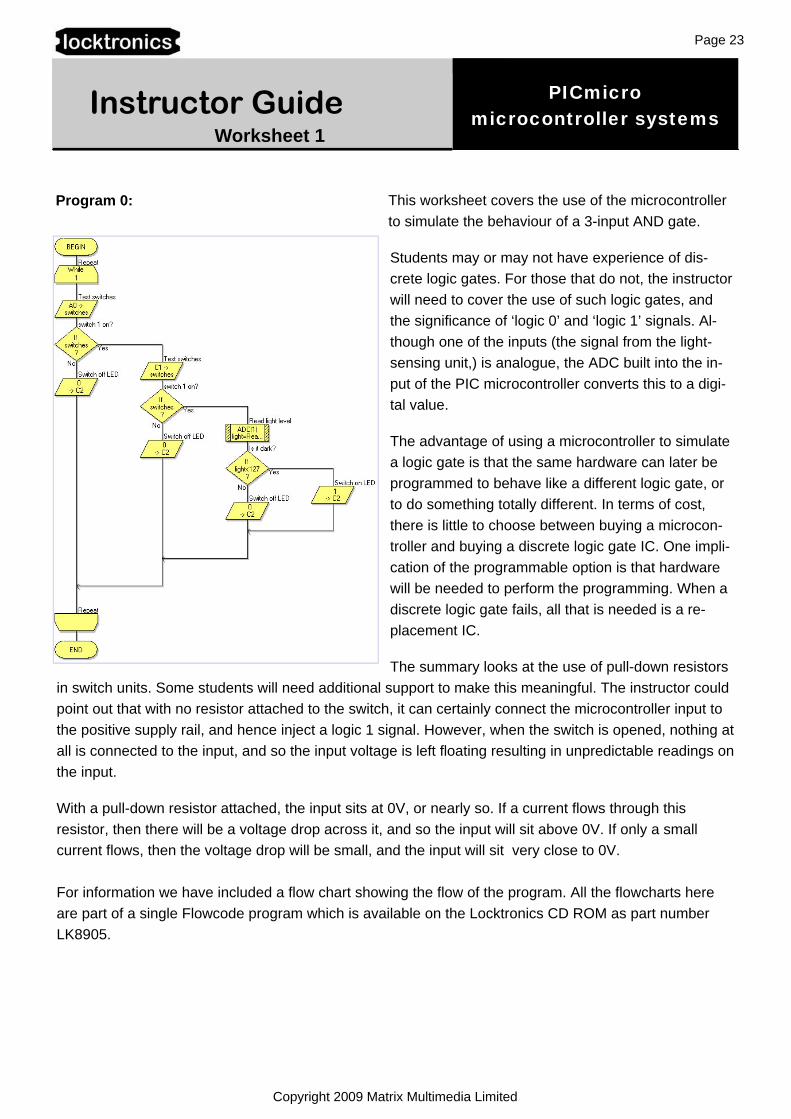
This worksheet covers the use of the microcontroller to simulate the behaviour of a 3-input AND gate.
Students may or may not have experience of dis-crete logic gates. For those that do not, the instructor will need to cover the use of such logic gates, and the significance of ‘logic 0’ and ‘logic 1’ signals. Al-though one of the inputs (the signal from the light-sensing unit,) is analogue, the ADC built into the in-put of the PIC microcontroller converts this to a digi-tal value.
The advantage of using a microcontroller to simulate a logic gate is that the same hardware can later be programmed to behave like a different logic gate, or to do something totally different. In terms of cost, there is little to choose between buying a microcon-troller and buying a discrete logic gate IC. One impli-cation of the programmable option is that hardware will be needed to perform the programming. When a discrete logic gate fails, all that is needed is a re-placement IC.
The summary looks at the use of pull-down resistors in switch units. Some students will need additional support to make this meaningful. The instructor could point out that with no resistor attached to the switch, it can certainly connect the microcontroller input to the positive supply rail, and hence inject a logic 1 signal. However, when the switch is opened, nothing at all is connected to the input, and so the input voltage is left floating resulting in unpredictable readings on the input.
With a pull-down resistor attached, the input sits at 0V, or nearly so. If a current flows through this resistor, then there will be a voltage drop across it, and so the input will sit above 0V. If only a small current flows, then the voltage drop will be small, and the input will sit very close to 0V. For information we have included a flow chart showing the flow of the program. All the flowcharts here are part of a single Flowcode program which is available on the Locktronics CD ROM as part number LK8905.
Program 0:
PICmicro microcontroller systems
Page 24
Copyright 2009 Matrix Multimedia Limited
Instructor Guide Worksheet 2
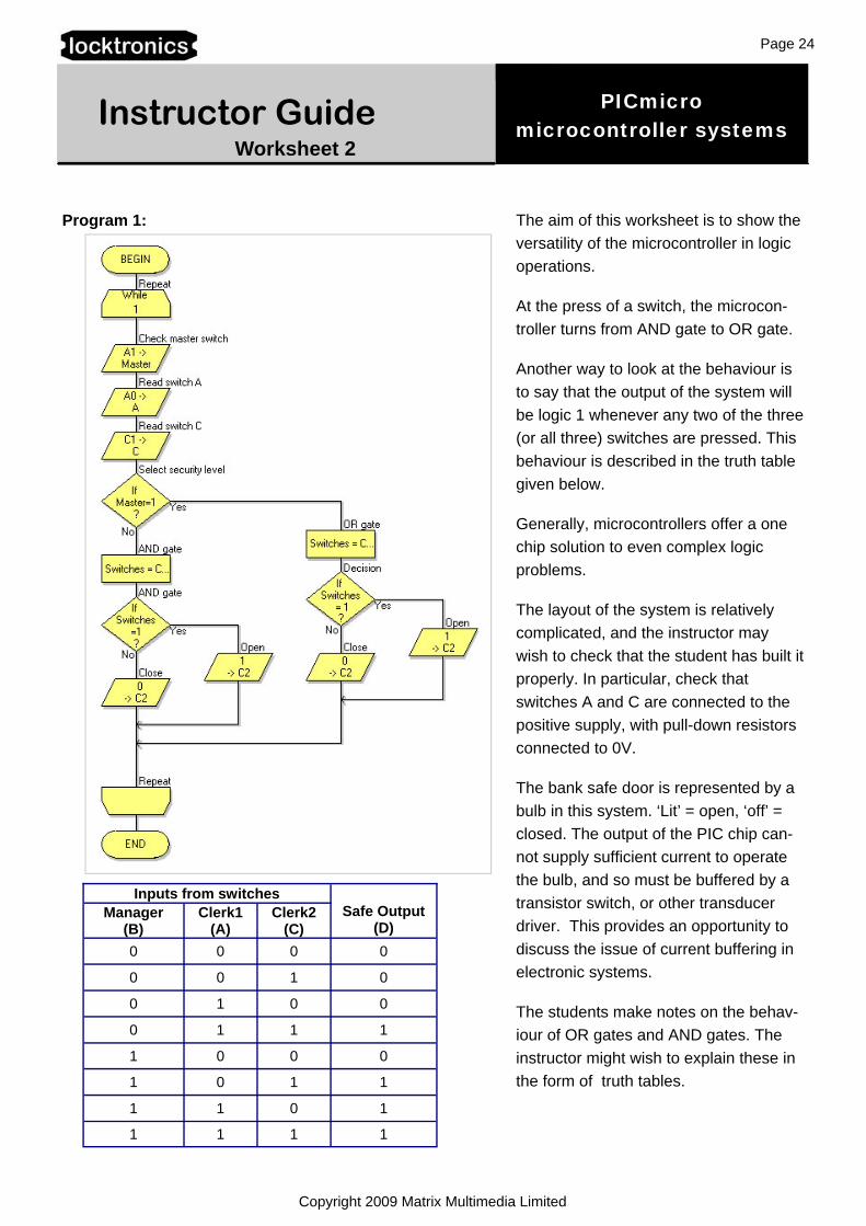
Program 1: The aim of this worksheet is to show the versatility of the microcontroller in logic operations.
At the press of a switch, the microcon-troller turns from AND gate to OR gate.
Another way to look at the behaviour is to say that the output of the system will be logic 1 whenever any two of the three (or all three) switches are pressed. This behaviour is described in the truth table given below.
Generally, microcontrollers offer a one chip solution to even complex logic problems.
The layout of the system is relatively complicated, and the instructor may wish to check that the student has built it properly. In particular, check that switches A and C are connected to the positive supply, with pull-down resistors connected to 0V.
The bank safe door is represented by a bulb in this system. ‘Lit’ = open, ‘off’ = closed. The output of the PIC chip can-not supply sufficient current to operate the bulb, and so must be buffered by a transistor switch, or other transducer driver. This provides an opportunity to discuss the issue of current buffering in electronic systems.
The students make notes on the behav-iour of OR gates and AND gates. The instructor might wish to explain these in the form of truth tables.
Inputs from switches Safe Output
(D) Manager
(B) Clerk1
(A) Clerk2
(C) 0 0 0 0
0 0 1 0
0 1 0 0
0 1 1 1
1 0 0 0
1 0 1 1
1 1 0 1
1 1 1 1
PICmicro microcontroller systems
Page 25
Copyright 2009 Matrix Multimedia Limited
Instructor Guide Worksheet 3
Program 2:
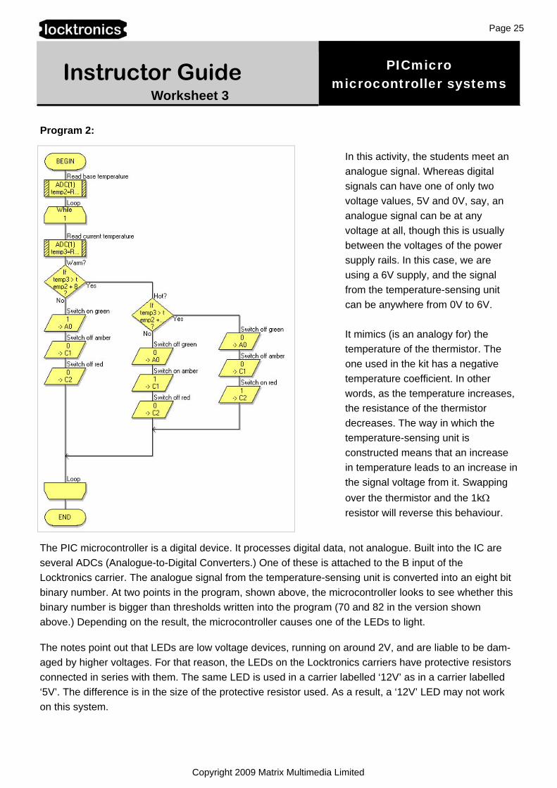
The PIC microcontroller is a digital device. It processes digital data, not analogue. Built into the IC are several ADCs (Analogue-to-Digital Converters.) One of these is attached to the B input of the Locktronics carrier. The analogue signal from the temperature-sensing unit is converted into an eight bit binary number. At two points in the program, shown above, the microcontroller looks to see whether this binary number is bigger than thresholds written into the program (70 and 82 in the version shown above.) Depending on the result, the microcontroller causes one of the LEDs to light.
The notes point out that LEDs are low voltage devices, running on around 2V, and are liable to be dam-aged by higher voltages. For that reason, the LEDs on the Locktronics carriers have protective resistors connected in series with them. The same LED is used in a carrier labelled ‘12V’ as in a carrier labelled ‘5V’. The difference is in the size of the protective resistor used. As a result, a ‘12V’ LED may not work on this system.
In this activity, the students meet an analogue signal. Whereas digital signals can have one of only two voltage values, 5V and 0V, say, an analogue signal can be at any voltage at all, though this is usually between the voltages of the power supply rails. In this case, we are using a 6V supply, and the signal from the temperature-sensing unit can be anywhere from 0V to 6V. It mimics (is an analogy for) the temperature of the thermistor. The one used in the kit has a negative temperature coefficient. In other words, as the temperature increases, the resistance of the thermistor decreases. The way in which the temperature-sensing unit is constructed means that an increase in temperature leads to an increase in the signal voltage from it. Swapping over the thermistor and the 1kΩ resistor will reverse this behaviour.

PICmicro microcontroller systems
Page 26
Copyright 2009 Matrix Multimedia Limited
Instructor Guide Worksheet 4
Program 3: One of the strengths of the Flowcode programming language is its ability to control complex components using code implanted in its ‘Component Macros’.
In this investigation, the program structure is very straightforward, as can be seen from the diagram opposite. However, the hard work takes place unseen, in the three Component Macros.
The first of these was used in the last investigation for the same job - turning an analogue signal from a temperature-sensing unit into an eight bit binary number.
In this investigation, the output signal is also analogue, or so it appears. The hotter the room, the faster the fan motor runs. However, a technique known as PWM (Pulse Width Modulation) is used to control the speed of the motor. This is created by the other two Component Macros. The value created from the temperature-sensing unit signal determines how long the motor is switched on within each pulse sent to the motor. In other words, the width of the pulse is modulated (adjusted) by the temperature signal.
When the room is hot, the pulse is wide, and as a result, the motor is turned on for longer. This effect is illustrated in the diagram.
Both sets of pulses have the same period and fre-quency. The second one will make the motor run faster, because, overall, it is switched on for longer.
The students make notes on this effect at the end of this investigation. At this point, the instructor could display the output signals from output D of the microcontroller on an oscilloscope, to support their learning.
As before, a transducer driver is required to provide sufficient current to run the motor. This acts as a current booster switch where a small current from the microcontroller controls a much bigger current through the motor.
pwm

PICmicro microcontroller systems
Page 27
Copyright 2009 Matrix Multimedia Limited
Instructor Guide Worksheet 5
Program 4: In this investigation, the microcontroller ap-pears to be doing two things at the same time! One output pulses, while another is held on for a preset time. Then that output goes low. Eventually, the pulsing on the other output stops.
In fact, both outputs are controlled by the same process - a number, monitored by the program, which continues to increase until eventually the pulsing stops, and the num-ber returns to zero.
These outputs are both controlled by the switch connected to input B. The program waits for it to be pressed, and then activates both outputs. When both are finished, the program returns to the beginning, waiting for the switch to be pressed again.
While count,20

PICmicro microcontroller systems
Page 28
Copyright 2009 Matrix Multimedia Limited
Instructor Guide Worksheet 6
Program 5: In this activity, students are introduced to the world of sequence controllers. While the activity is limited in scope, switching on each of three LEDs in turn, it is an example of a hugely important tech-nology. Automated production lines are common in manufacturing industry. The processes that take place are controlled and timed by microcontrollers like the one used here. The students could be set the task of researching an example of sequential control. They could look at examples in a local industry. Alternatively, they could be set the task of designing the flowchart for a system such as an automatic barrier in a car park, or for a set of traffic lights at a junction that includes a pedestrian crossing.
The instructor should make sure that students are clear about what is happening here. There are two actions taking place for each LED. Each is switched on, and then, after a time delay, switched off. The time delay depends on an analogue voltage from a variable voltage supply. The ADC in the PIC chip turns this into a digital value which then determines the duration of the delay.

PICmicro microcontroller systems
Page 29
Copyright 2009 Matrix Multimedia Limited
Instructor Guide Worksheet 7
Program 6:
This is a general purpose timing program. The input devices are two switch units and a variable voltage supply unit, though none of these initiates the program. Instead, pressing the Reset switch on the Locktronics PIC carrier starts things off.
After the Reset switch is pressed, the program looks to see if either of the switches on the switch units has been closed. If one or both switches are closed, the LED lights for a time which depends on which switch was closed. If neither switch is closed, the delay time is set by the signal from the variable voltage supply unit. Closing one of the switches creates a time delay of about five seconds. Closing the other creates a delay of about ten seconds. Closing both sets the delay to about fifteen seconds.
As usual, the instructor should check that the students have assembled the system correctly, paying par-ticular attention to the variable resistor carrier, which is used as the variable voltage supply unit.
PICmicro microcontroller systems
Page 30
Copyright 2009 Matrix Multimedia Limited
Instructor Guide Worksheet 8
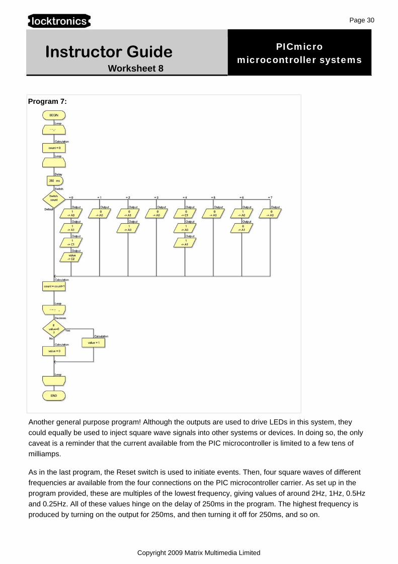
Program 7:
Another general purpose program! Although the outputs are used to drive LEDs in this system, they could equally be used to inject square wave signals into other systems or devices. In doing so, the only caveat is a reminder that the current available from the PIC microcontroller is limited to a few tens of milliamps.
As in the last program, the Reset switch is used to initiate events. Then, four square waves of different frequencies ar available from the four connections on the PIC microcontroller carrier. As set up in the program provided, these are multiples of the lowest frequency, giving values of around 2Hz, 1Hz, 0.5Hz and 0.25Hz. All of these values hinge on the delay of 250ms in the program. The highest frequency is produced by turning on the output for 250ms, and then turning it off for 250ms, and so on.