picoscope 4000 series (a api) programmer's guidethe api driver depends on a kernel driver,...
TRANSCRIPT
Copyright © 2008-2014 Pico Technology Ltd. All rights reserved.
PicoScope 4000 Series (A API)
Programmer's Guide
ps4000apg.en r1
PC Oscilloscopes


IPicoScope 4000 Series (A API) Programmer's Guide
Copyright © 2008-2014 Pico Technology Ltd. All rights reserved. ps4000apg.en r1
Contents....................................................................................................................................11 Welcome
....................................................................................................................................22 Introduction
........................................................................................................................................21 Software licence conditions
........................................................................................................................................22 Trademarks
........................................................................................................................................33 Company details
........................................................................................................................................34 System requirements
........................................................................................................................................45 Installation instructions
....................................................................................................................................53 Programming with the PicoScope 4000 Series (A API)
........................................................................................................................................51 Driver
........................................................................................................................................52 Voltage ranges
........................................................................................................................................63 Channel selection
........................................................................................................................................64 Triggering
........................................................................................................................................75 Downsampling
........................................................................................................................................86 Sampling modes
......................................................................................................................................................................81 Block mode ......................................................................................................................................................................102 Rapid block mode ......................................................................................................................................................................153 Streaming mode ......................................................................................................................................................................164 Retrieving stored data
........................................................................................................................................177 Timebases
........................................................................................................................................178 Combining several oscilloscopes
....................................................................................................................................184 API functions
........................................................................................................................................201 ps4000aBlockReady
........................................................................................................................................212 ps4000aChangePowerSource
........................................................................................................................................223 ps4000aCurrentPowerSource
........................................................................................................................................234 ps4000aCloseUnit
........................................................................................................................................245 ps4000aDataReady
........................................................................................................................................256 ps4000aEnumerateUnits
........................................................................................................................................267 ps4000aFlashLed
........................................................................................................................................278 ps4000aGetAnalogueOffset
........................................................................................................................................289 ps4000aGetChannelInformation
........................................................................................................................................2910 ps4000aGetMaxDownSampleRatio
........................................................................................................................................3011 ps4000aGetMaxSegments
........................................................................................................................................3112 ps4000aGetNoOfCaptures
........................................................................................................................................3213 ps4000aGetNoOfProcessedCaptures
........................................................................................................................................3314 ps4000aGetStreamingLatestValues
........................................................................................................................................3415 ps4000aGetTimebase
........................................................................................................................................3516 ps4000aGetTimebase2
........................................................................................................................................3617 ps4000aGetTriggerTimeOffset
........................................................................................................................................3718 ps4000aGetTriggerTimeOffset64
........................................................................................................................................3819 ps4000aGetUnitInfo
ContentsII
Copyright © 2008-2014 Pico Technology Ltd. All rights reserved.ps4000apg.en r1
........................................................................................................................................3920 ps4000aGetValues
........................................................................................................................................4021 ps4000aGetValuesAsync
........................................................................................................................................4122 ps4000aGetValuesBulk
........................................................................................................................................4223 ps4000aGetValuesOverlapped
........................................................................................................................................4324 ps4000aGetValuesOverlappedBulk
........................................................................................................................................4425 ps4000aIsLedFlashing
........................................................................................................................................4526 ps4000aIsReady
........................................................................................................................................4627 ps4000aIsTriggerOrPulseWidthQualifierEnabled
........................................................................................................................................4728 ps4000aMaximumValue
........................................................................................................................................4829 ps4000aMinimumValue
........................................................................................................................................4930 ps4000aMemorySegments
........................................................................................................................................5031 ps4000aNoOfStreamingValues
........................................................................................................................................5132 ps4000aOpenUnit
........................................................................................................................................5233 ps4000aOpenUnitAsync
........................................................................................................................................5334 ps4000aOpenUnitProgress
........................................................................................................................................5435 ps4000aRunBlock
........................................................................................................................................5636 ps4000aRunStreaming
........................................................................................................................................5837 ps4000aSetBandwidthFilter
........................................................................................................................................5938 ps4000aSetChannel
........................................................................................................................................6039 ps4000aSetDataBuffer
........................................................................................................................................6140 ps4000aSetDataBuffers
........................................................................................................................................6241 ps4000aSetEts
........................................................................................................................................6342 ps4000aSetEtsTimeBuffer
........................................................................................................................................6443 ps4000aSetEtsTimeBuffers
........................................................................................................................................6544 ps4000aSetNoOfCaptures
........................................................................................................................................6645 ps4000aSetPulseWidthQualifierConditions
........................................................................................................................................6746 ps4000aSetPulseWidthQualifierProperties
........................................................................................................................................6847 ps4000aSetSigGenArbitrary
......................................................................................................................................................................711 AWG index modes ........................................................................................................................................7248 ps4000aSetSigGenBuiltIn
........................................................................................................................................7449 ps4000aSetSigGenPropertiesArbitrary
........................................................................................................................................7550 ps4000aSetSigGenPropertiesBuiltIn
........................................................................................................................................7651 ps4000aSetSimpleTrigger
........................................................................................................................................7752 ps4000aSetTriggerChannelConditions
......................................................................................................................................................................781 PS4000A_CONDITION structure ........................................................................................................................................7953 ps4000aSetTriggerChannelDirections
......................................................................................................................................................................801 PS4000A_DIRECTION structure ........................................................................................................................................8154 ps4000aSetTriggerChannelProperties
......................................................................................................................................................................821 PS4000A_TRIGGER_CHANNEL_PROPERTIES structure ........................................................................................................................................8355 ps4000aSetTriggerDelay
........................................................................................................................................8456 ps4000aSigGenSoftwareControl
........................................................................................................................................8557 ps4000aStop
........................................................................................................................................8658 ps4000aStreamingReady
....................................................................................................................................875 Enumerated types and constants

IIIPicoScope 4000 Series (A API) Programmer's Guide
Copyright © 2008-2014 Pico Technology Ltd. All rights reserved. ps4000apg.en r1
....................................................................................................................................886 Driver status codes
....................................................................................................................................897 Programming examples
........................................................................................................................................891 C
........................................................................................................................................892 Excel
........................................................................................................................................893 LabVIEW
....................................................................................................................................928 Glossary
....................................................................................................................................95Index

PicoScope 4000 Series (A API) Programmer's Guide 1
Copyright © 2008-2014 Pico Technology Ltd. All rights reserved. ps4000apg.en r1
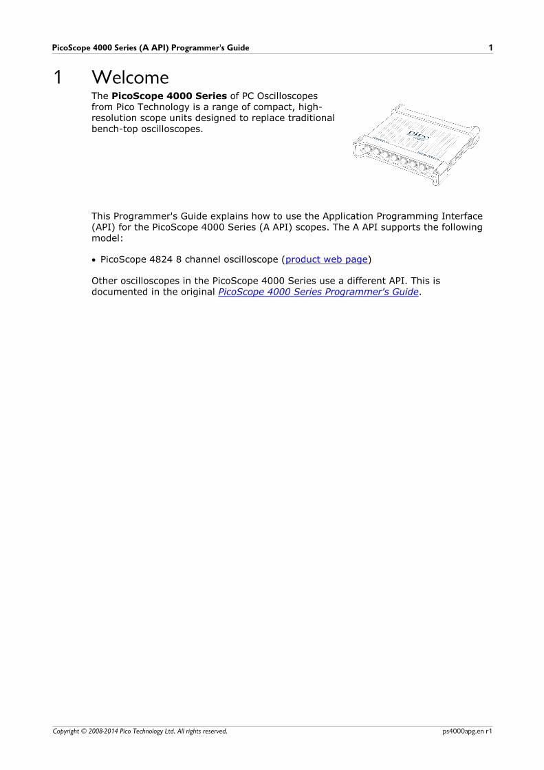
1 WelcomeThe PicoScope 4000 Series of PC Oscilloscopesfrom Pico Technology is a range of compact, high-resolution scope units designed to replace traditionalbench-top oscilloscopes.
This Programmer's Guide explains how to use the Application Programming Interface(API) for the PicoScope 4000 Series (A API) scopes. The A API supports the followingmodel:
PicoScope 4824 8 channel oscilloscope (product web page)
Other oscilloscopes in the PicoScope 4000 Series use a different API. This isdocumented in the original PicoScope 4000 Series Programmer's Guide.
Introduction2
Copyright © 2008-2014 Pico Technology Ltd. All rights reserved.ps4000apg.en r1
2 Introduction2.1 Software licence conditions
The material contained in this release is licensed, not sold. Pico Technology Limitedgrants a licence to the person who installs this software, subject to the conditionslisted below.
Access. The licensee agrees to allow access to this software only to persons who havebeen informed of these conditions and agree to abide by them.
Usage. The software in this release is for use only with Pico products or with datacollected using Pico products.
Copyright. Pico Technology Ltd. claims the copyright of, and retains the rights to, allmaterial (software, documents, etc.) contained in this SDK except the exampleprograms. You may copy and distribute the SDK without restriction, as long as you donot remove any Pico Technology copyright statements. The example programs in theSDK may be modified, copied and distributed for the purpose of developing programsto collect data using Pico products.
Liability. Pico Technology and its agents shall not be liable for any loss, damage orinjury, howsoever caused, related to the use of Pico Technology equipment orsoftware, unless excluded by statute.
Fitness for purpose. As no two applications are the same, Pico Technology cannotguarantee that its equipment or software is suitable for a given application. It is yourresponsibility, therefore, to ensure that the product is suitable for your application.
Mission-critical applications. This software is intended for use on a computer thatmay be running other software products. For this reason, one of the conditions of thelicence is that it excludes use in mission-critical applications, for example life supportsystems.
Viruses. This software was continuously monitored for viruses during production, butyou are responsible for virus-checking the software once it is installed.
Support. If you are dissatisfied with the performance of this software, please contactour technical support staff, who will try to fix the problem within a reasonable time. Ifyou are still dissatisfied, please return the product and software to your supplier within28 days of purchase for a full refund.
Upgrades. We provide upgrades, free of charge, from our web site atwww.picotech.com. We reserve the right to charge for updates or replacements sentout on physical media.
2.2 TrademarksWindows, Excel and Visual Basic are registered trademarks or trademarks ofMicrosoft Corporation in the USA and other countries. LabVIEW is a registeredtrademark of National Instruments Corporation.
Pico Technology and PicoScope are trademarks of Pico Technology Limited,registered in the United Kingdom and other countries.
PicoScope and Pico Technology are registered in the U.S. Patent and TrademarkOffice.
PicoScope 4000 Series (A API) Programmer's Guide 3
Copyright © 2008-2014 Pico Technology Ltd. All rights reserved. ps4000apg.en r1
2.3 Company detailsAddress: Pico Technology
James HouseColmworth Business ParkSt. NeotsCambridgeshirePE19 8YPUnited Kingdom
Phone: +44 (0) 1480 396 395 Fax: +44 (0) 1480 396 296
Email: Technical Support: [email protected]: [email protected]
Web site: www.picotech.com
2.4 System requirementsUsing with PicoScope for Windows
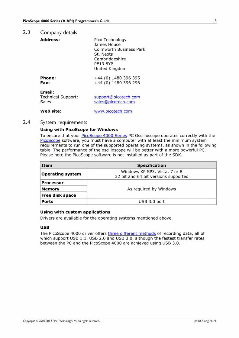
To ensure that your PicoScope 4000 Series PC Oscilloscope operates correctly with thePicoScope software, you must have a computer with at least the minimum systemrequirements to run one of the supported operating systems, as shown in the followingtable. The performance of the oscilloscope will be better with a more powerful PC.Please note the PicoScope software is not installed as part of the SDK.
Item Specification
Operating systemWindows XP SP3, Vista, 7 or 8
32 bit and 64 bit versions supported
Processor
As required by WindowsMemory
Free disk space
Ports USB 3.0 port
Using with custom applications
Drivers are available for the operating systems mentioned above.
USB
The PicoScope 4000 driver offers three different methods of recording data, all ofwhich support USB 1.1, USB 2.0 and USB 3.0, although the fastest transfer ratesbetween the PC and the PicoScope 4000 are achieved using USB 3.0.

Introduction4
Copyright © 2008-2014 Pico Technology Ltd. All rights reserved.ps4000apg.en r1
2.5 Installation instructions
IMPORTANTDo not connect your PicoScope 4000 Series scope device to the PC before you
have installed the Pico Technology software. If you do, Windows might not recognise the scope device correctly.
Procedure
Follow the instructions in the Installation Guide included with your product package.Connect your PC Oscilloscope to the PC using the USB cable supplied.
Checking the installation
Once you have installed the software and connected the PC Oscilloscope to the PC,start the PicoScope software. PicoScope should now display any signal connected tothe scope inputs. If a probe is connected to your oscilloscope, you should see a small50 or 60 hertz signal in the oscilloscope window when you touch the probe tip withyour finger.
Moving your PicoScope PC Oscilloscope to another USB port
Windows XP SP3When you first installed the PicoScope 4000 Series PC Oscilloscope by plugging it intoa USB port, Windows associated the Pico driver with that port. If you later move theoscilloscope to a different USB port, Windows will display the "New Hardware FoundWizard" again. When this occurs, just click "Next" in the wizard to repeat theinstallation. If Windows gives a warning about Windows Logo Testing, click "ContinueAnyway". As all the software you need is already installed on your computer, there isno need to insert the Pico Software CD again.
Windows Vista, 7 and 8The process is automatic. When you move the device from one port to another,Windows displays an "Installing device driver software" message and then a"PicoScope 4000 Series PC Oscilloscope" message. The PC Oscilloscope is then readyfor use.
PicoScope 4000 Series (A API) Programmer's Guide 5
Copyright © 2008-2014 Pico Technology Ltd. All rights reserved. ps4000apg.en r1
3 Programming with the PicoScope 4000 Series (AAPI)The ps4000a.dll dynamic link library in your PicoScope installation directory allows
you to program a PicoScope 4000 Series oscilloscope using standard C function calls.
A typical program for capturing data consists of the following steps:
Open the scope unit.Set up the input channels with the required voltage ranges and coupling mode.Set up triggering.Start capturing data. (See Sampling modes, where programming is discussed inmore detail.)Wait until the scope unit is ready.Stop capturing data.Copy data to a buffer.Close the scope unit.
Numerous sample programs are installed with your PicoScope software. These showhow to use the functions of the driver software in each of the modes available.
3.1 DriverYour application will communicate with a PicoScope 4000 API driver called ps4000a.dll. The driver exports the PicoScope 4000 function definitions in
standard C format, but this does not limit you to programming in C. You can use theAPI with any programming language that supports standard C calls.
The API driver depends on a kernel driver, CyUSB3.sys, which has a 64-bit version
and a 32-bit version and works with all operating systems except Windows 8. Windows8 uses WinUsb.sys on both 32-bit and 64-bit versions. Your application does not
need to call the kernel driver. Once you have installed the PicoScope 6 software,Windows automatically installs the kernel driver when you plug in the PicoScope 4000Series PC Oscilloscope for the first time.
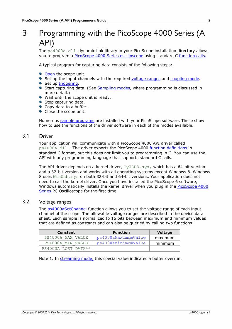
3.2 Voltage rangesThe ps4000aSetChannel function allows you to set the voltage range of each inputchannel of the scope. The allowable voltage ranges are described in the device datasheet. Each sample is normalized to 16 bits between maximum and minimum valuesthat are defined as constants and can also be queried by calling two functions:
Constant Function Voltage
PS4000A_MAX_VALUE ps4000aMaximumValue maximum
PS4000A_MIN_VALUE ps4000aMinimumValue minimum
PS4000A_LOST_DATA[1]
Note 1. In streaming mode, this special value indicates a buffer overrun.
Programming with the PicoScope 4000 Series (A API)6
Copyright © 2008-2014 Pico Technology Ltd. All rights reserved.ps4000apg.en r1
3.3 Channel selectionYou can switch each channel on and off, and set its coupling mode to either AC or DC,using the ps4000aSetChannel function.
DC coupling: The scope accepts all input frequencies from zero (DC) up to itsmaximum analog bandwidth.
AC coupling: The scope accepts input frequencies from a few hertz up to itsmaximum analog bandwidth. The lower –3 dB cutoff frequency isabout 1 hertz.
3.4 TriggeringPicoScope 4000 Series PC Oscilloscopes can either start collecting data immediately, orbe programmed to wait for a trigger event to occur. In both cases you need to use thePicoScope 4000 trigger functions:
ps4000aSetTriggerChannelConditionsps4000aSetTriggerChannelDirectionsps4000aSetTriggerChannelPropertiesps4000aSetTriggerDelay (optional)
These can be run collectively by calling ps4000aSetSimpleTrigger, or singly.
A trigger event can occur when one of the signal or trigger input channels crosses athreshold voltage on either a rising or a falling edge.
The driver supports these triggering methods:
Simple EdgeAdvanced EdgeWindowingPulse widthLogicDelayDrop-outRunt
PicoScope 4000 Series (A API) Programmer's Guide 7
Copyright © 2008-2014 Pico Technology Ltd. All rights reserved. ps4000apg.en r1
3.5 DownsamplingThe driver can optionally apply a data reduction, or downsampling, process beforereturning data to the application. Downsampling is done by firmware on the deviceand is generally faster than using the PC's own processor(s). You instruct the driver todownsample by passing a downSampleRatioMode argument to one of the data-
retrieval functions such as ps4000aGetValues. You must also pass in an argument
called downSampleRatio: how many raw samples are to be combined into each
processed sample.
You can optionally retrieve data using more than one downsampling mode with asingle call to ps4000aGetValues. Set up a buffer for each downsampling mode by
calling ps4000aSetDataBuffer. Then, when calling ps4000aGetValues, set
downSampleRatioMode to the bitwise OR of the required downsampling modes.
The available downsampling modes are:
PS4000A_RATIO_MODE_NONE (0)
No downsampling is performed. The downSampleRatio parameter is ignored.
PS4000A_RATIO_MODE_AGGREGATE (1)
The aggregate method generates two buffers of data for every channel, onecontaining the minimum sample value for every block of downSampleRatio raw
samples, and the other containing the maximum value.
PS4000A_RATIO_MODE_DECIMATE (2)
The decimate method returns the first sample in every block of downSampleRatiosuccessive samples and discards all the other samples.
PS4000A_RATIO_MODE_AVERAGE (4)
The average method returns the sum of all the samples in each block ofdownSampleRatio samples, divided by the size of the block.
PS4000A_RATIO_MODE_DISTRIBUTION (8)
This mode is not implemented.

Programming with the PicoScope 4000 Series (A API)8
Copyright © 2008-2014 Pico Technology Ltd. All rights reserved.ps4000apg.en r1
3.6 Sampling modesPicoScope 4000 Series PC Oscilloscopes can run in various sampling modes.
Block mode. In this mode, the scope stores data in internal RAM and thentransfers it to the PC. When the data has been collected it is possible to examinethe data, with an optional downsampling factor. The data is lost when a new run isstarted in the same segment, the settings are changed, or the scope is powereddown.
Rapid block mode. This is a variant of block mode that allows you to capture morethan one waveform at a time with a minimum of delay between captures. You canuse downsampling in this mode if you wish.
Streaming mode. In this mode, data is passed directly to the PC without beingstored in the scope's internal RAM. This enables long periods of slow data collectionfor chart recorder and data-logging applications. Streaming mode provides faststreaming at up to 160 MS/s with a USB 3.0 connection. Downsampling andtriggering are supported in this mode.
In all sampling modes, the driver returns data asynchronously using a callback. This isa call to one of the functions in your own application. When you request data from thescope, you pass to the driver a pointer to your callback function. When the driver haswritten the data to your buffer, it makes a callback (calls your function) to signal thatthe data is ready. The callback function then signals to the application that the data isavailable.
Because the callback is called asynchronously from the rest of your application, in aseparate thread, you must ensure that it does not corrupt any global variables while itruns.
In block mode, you can also poll the driver instead of using a callback.
3.6.1 Block mode
In block mode, the computer prompts a PicoScope 4000 Series PC Oscilloscope tocollect a block of data into its internal memory. When the oscilloscope has collectedthe whole block, it signals that it is ready and then transfers the whole block to thecomputer's memory through the USB port.
Block size. The maximum number of values depends upon the size of theoscilloscope's memory. The memory buffer is shared between the enabled channels,so if two channels are enabled, each receives half the memory. These features arehandled transparently by the driver. The block size also depends on the number ofmemory segments in use (see ps4000aMemorySegments).
Sampling rate. The maximum sampling rate of 80 MS/s can be achieved with upto four channels enabled. With five or more channels enabled, the sampling rate isreduced to 40 MS/s.
Setup time. The driver normally performs a number of setup operations, which cantake up to 50 milliseconds, before collecting each block of data. If you need tocollect data with the minimum time interval between blocks, use rapid block modeand avoid calling setup functions between calls to ps4000aRunBlock,
ps4000aStop and ps4000aGetValues.
PicoScope 4000 Series (A API) Programmer's Guide 9
Copyright © 2008-2014 Pico Technology Ltd. All rights reserved. ps4000apg.en r1
Downsampling. When the data has been collected, you can set an optionaldownsampling factor and examine the data. Downsampling is the process ofreducing the amount of data by combining adjacent samples using one of severalalgorithms. It is useful for zooming in and out of the data without having torepeatedly transfer the entire contents of the scope's buffer to the PC.
Memory segmentation. The scope's internal memory can be divided intosegments so that you can capture several waveforms in succession. Configure thisusing ps4000aMemorySegments.
Data retention. The data is lost when a new run is started in the same segment,the number of segments is changed, or the scope is powered down.
See Using block mode for programming details.
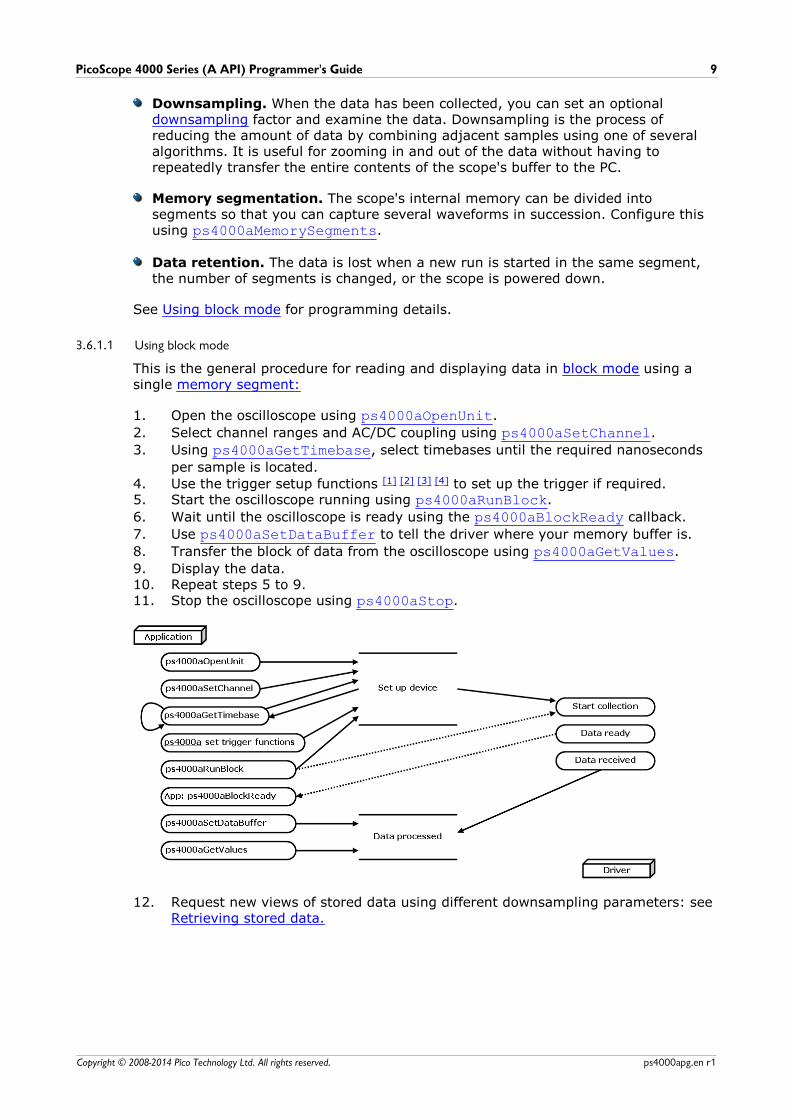
3.6.1.1 Using block mode
This is the general procedure for reading and displaying data in block mode using asingle memory segment:
1. Open the oscilloscope using ps4000aOpenUnit.
2. Select channel ranges and AC/DC coupling using ps4000aSetChannel.
3. Using ps4000aGetTimebase, select timebases until the required nanoseconds
per sample is located.
4. Use the trigger setup functions [1] [2] [3] [4] to set up the trigger if required.5. Start the oscilloscope running using ps4000aRunBlock.
6. Wait until the oscilloscope is ready using the ps4000aBlockReady callback.
7. Use ps4000aSetDataBuffer to tell the driver where your memory buffer is.
8. Transfer the block of data from the oscilloscope using ps4000aGetValues.
9. Display the data.10. Repeat steps 5 to 9.11. Stop the oscilloscope using ps4000aStop.
12. Request new views of stored data using different downsampling parameters: seeRetrieving stored data.
Programming with the PicoScope 4000 Series (A API)10
Copyright © 2008-2014 Pico Technology Ltd. All rights reserved.ps4000apg.en r1
3.6.2 Rapid block mode
In normal block mode, the PicoScope 4000 Series scopes collect one waveform at atime. You start the the device running, wait until all samples are collected by thedevice, and then download the data to the PC or start another run. There is a timeoverhead of tens of milliseconds associated with starting a run, causing a gap betweenwaveforms. When you collect data from the device, there is another minimum timeoverhead which is most noticeable when using a small number of samples.
Rapid block mode allows you to sample several waveforms at a time with theminimum time between waveforms. It reduces the gap from milliseconds to about 2.5microseconds.
See Using rapid block mode for details.
3.6.2.1 Using rapid block mode
You can use rapid block mode with or without downsampling. The followingprocedure shows you how to use it without downsampling.
Without downsampling
1. Open the oscilloscope using ps4000aOpenUnit.
2. Select channel ranges and AC/DC coupling using ps4000aSetChannel.
3. Using ps4000aGetTimebase, select timebases until the required nanoseconds
per sample is located.
4. Use the trigger setup functions [1] [2] [3] [4] to set up the trigger if required.5. Set the number of memory segments equal to or greater than the number of
captures required using ps4000aMemorySegments. Use
ps4000aSetNoOfCaptures before each run to specify the number of
waveforms to capture.6. Start the oscilloscope running using ps4000aRunBlock.
7. Wait until the oscilloscope is ready using the ps4000aBlockReady callback.
8. Use ps4000aSetDataBuffer to tell the driver where your memory buffers are.
9. Transfer the blocks of data from the oscilloscope usingps4000aGetValuesBulk.
10. Retrieve the time offset for each data segment usingps4000aGetValuesTriggerTimeOffsetBulk.
11. Display the data.12. Repeat steps 6 to 11 if necessary.13. Stop the oscilloscope using ps4000aStop.
With downsampling
To use rapid block mode with downsampling, follow steps 1 to 9 above and thenproceed as follows:
10a. Call ps4000aSetDataBuffers to set up one pair of buffers for every waveform
segment required.11a. Call ps4000aGetValues for each pair of buffers.
12a. Retrieve the time offset for each data segment usingps4000aGetTriggerTimeOffset64.
Continue from step 13 above.
PicoScope 4000 Series (A API) Programmer's Guide 11
Copyright © 2008-2014 Pico Technology Ltd. All rights reserved. ps4000apg.en r1
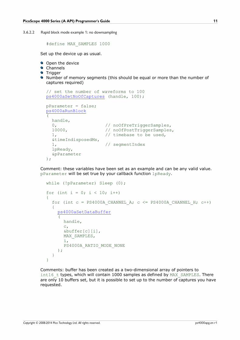
3.6.2.2 Rapid block mode example 1: no downsampling
#define MAX_SAMPLES 1000
Set up the device up as usual.
Open the deviceChannelsTriggerNumber of memory segments (this should be equal or more than the number ofcaptures required)
// set the number of waveforms to 100ps4000aSetNoOfCaptures (handle, 100);
pParameter = false;ps4000aRunBlock(
handle,0, // noOfPreTriggerSamples,10000, // noOfPostTriggerSamples,1, // timebase to be used,&timeIndisposedMs,1, // segmentIndexlpReady,&pParameter
);
Comment: these variables have been set as an example and can be any valid value. pParameter will be set true by your callback function lpReady.
while (!pParameter) Sleep (0);
for (int i = 0; i < 10; i++){
for (int c = PS4000A_CHANNEL_A; c <= PS4000A_CHANNEL_H; c++){
ps4000aSetDataBuffer(
handle,c,&buffer[c][i],MAX_SAMPLES,i,PS4000A_RATIO_MODE_NONE
);}
}
Comments: buffer has been created as a two-dimensional array of pointers to int16_t types, which will contain 1000 samples as defined by MAX_SAMPLES. There
are only 10 buffers set, but it is possible to set up to the number of captures you haverequested.
Programming with the PicoScope 4000 Series (A API)12
Copyright © 2008-2014 Pico Technology Ltd. All rights reserved.ps4000apg.en r1
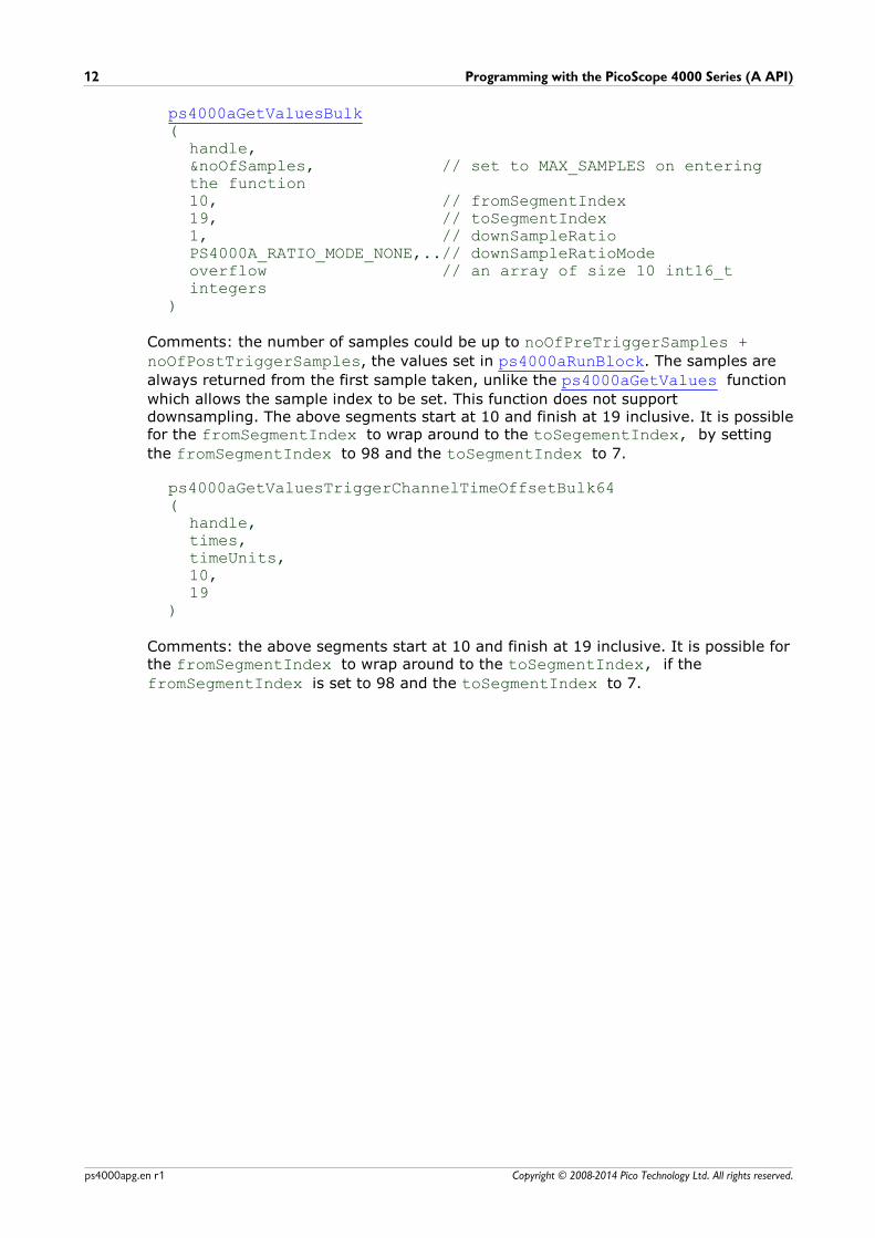
ps4000aGetValuesBulk(
handle,&noOfSamples, // set to MAX_SAMPLES on enteringthe function10, // fromSegmentIndex19, // toSegmentIndex1, // downSampleRatioPS4000A_RATIO_MODE_NONE,..// downSampleRatioModeoverflow // an array of size 10 int16_tintegers
)
Comments: the number of samples could be up to noOfPreTriggerSamples +noOfPostTriggerSamples, the values set in ps4000aRunBlock. The samples are
always returned from the first sample taken, unlike the ps4000aGetValues function
which allows the sample index to be set. This function does not supportdownsampling. The above segments start at 10 and finish at 19 inclusive. It is possiblefor the fromSegmentIndex to wrap around to the toSegementIndex, by setting
the fromSegmentIndex to 98 and the toSegmentIndex to 7.
ps4000aGetValuesTriggerChannelTimeOffsetBulk64(
handle,times,timeUnits,10,19
)
Comments: the above segments start at 10 and finish at 19 inclusive. It is possible forthe fromSegmentIndex to wrap around to the toSegmentIndex, if the
fromSegmentIndex is set to 98 and the toSegmentIndex to 7.
PicoScope 4000 Series (A API) Programmer's Guide 13
Copyright © 2008-2014 Pico Technology Ltd. All rights reserved. ps4000apg.en r1
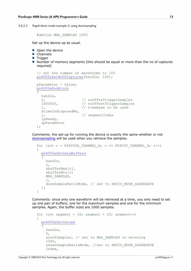
3.6.2.3 Rapid block mode example 2: using downsampling
#define MAX_SAMPLES 1000
Set up the device up as usual.
Open the deviceChannelsTriggerNumber of memory segments (this should be equal or more than the no of capturesrequired)
// set the number of waveforms to 100ps4000aSetNoOfCaptures(handle, 100);
pParameter = false;ps4000aRunBlock(
handle,0, // noOfPreTriggerSamples1000000, // noOfPostTriggerSamples1, // timebase to be used&timeIndisposedMs,1, // segmentIndexlpReady,&pParameter
);
Comments: the set-up for running the device is exactly the same whether or not downsampling will be used when you retrieve the samples.
for (int c = PS4000A_CHANNEL_A; c <= PS4000_CHANNEL_H; c++){
ps4000aSetDataBuffers(
handle,c,&bufferMax[c],&bufferMin[c]MAX_SAMPLES,1,downSampleRatioMode, // set to RATIO_MODE_AGGREGATE
);}
Comments: since only one waveform will be retrieved at a time, you only need to setup one pair of buffers; one for the maximum samples and one for the minimumsamples. Again, the buffer sizes are 1000 samples.
for (int segment = 10; segment < 20; segment++){
ps4000aGetValues(
handle,0,&noOfSamples, // set to MAX_SAMPLES on entering1000,&downSampleRatioMode, //set to RATIO_MODE_AGGREGATEindex,

Programming with the PicoScope 4000 Series (A API)14
Copyright © 2008-2014 Pico Technology Ltd. All rights reserved.ps4000apg.en r1
overflow );
ps4000aGetTriggerTimeOffset64(
handle,&time,&timeUnits,index
)}
Comments: each waveform is retrieved one at a time from the driver with anaggregation of 1000.
PicoScope 4000 Series (A API) Programmer's Guide 15
Copyright © 2008-2014 Pico Technology Ltd. All rights reserved. ps4000apg.en r1
3.6.3 Streaming mode
Streaming mode can capture data without the gaps that occur between blocks whenusing block mode. It can transfer data to the PC at speeds of up to 160 MS/s,depending on the computer's performance. This makes it suitable for high-speeddata acquisition, allowing you to capture long data sets limited only by thecomputer's memory.
Downsampling. The driver returns downsampled readings while the device isstreaming. If the downsampling ratio is set to 1, only one buffer is returned perchannel. When the downsampling ratio is greater than 1 and aggregation mode isselected, two buffers (maximum and minimum) per channel are returned.
Memory segmentation. The memory can be divided into segments to reduce thelatency of data transfers to the PC. However, this increases the risk of losing data ifthe PC cannot keep up with the device's sampling rate.
See Using streaming mode for programming details.
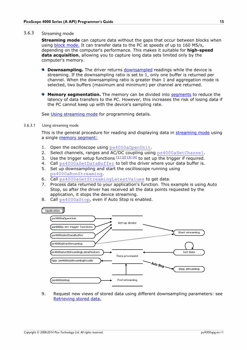
3.6.3.1 Using streaming mode
This is the general procedure for reading and displaying data in streaming mode usinga single memory segment:
1. Open the oscilloscope using ps4000aOpenUnit.
2. Select channels, ranges and AC/DC coupling using ps4000aSetChannel.
3. Use the trigger setup functions [1] [2] [3] [4] to set up the trigger if required.4. Call ps4000aSetDataBuffer to tell the driver where your data buffer is.
5. Set up downsampling and start the oscilloscope running usingps4000aRunStreaming.
6. Call ps4000aGetStreamingLatestValues to get data.
7. Process data returned to your application's function. This example is using AutoStop, so after the driver has received all the data points requested by theapplication, it stops the device streaming.
8. Call ps4000aStop, even if Auto Stop is enabled.
9. Request new views of stored data using different downsampling parameters: seeRetrieving stored data.
Programming with the PicoScope 4000 Series (A API)16
Copyright © 2008-2014 Pico Technology Ltd. All rights reserved.ps4000apg.en r1
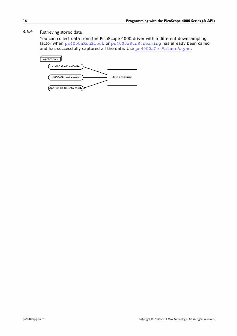
3.6.4 Retrieving stored data
You can collect data from the PicoScope 4000 driver with a different downsamplingfactor when ps4000aRunBlock or ps4000aRunStreaming has already been called
and has successfully captured all the data. Use ps4000aGetValuesAsync.
PicoScope 4000 Series (A API) Programmer's Guide 17
Copyright © 2008-2014 Pico Technology Ltd. All rights reserved. ps4000apg.en r1
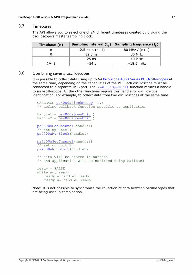
3.7 Timebases
The API allows you to select one of 232 different timebases created by dividing theoscilloscope's master sampling clock.
Timebase (n) Sampling interval (tS) Sampling frequency (fS)
n 12.5 ns × (n+1) 80 MHz / (n+1)
0 12.5 ns 80 MHz
1 25 ns 40 MHz
232–1 ~54 s ~18.6 mHz
3.8 Combining several oscilloscopesIt is possible to collect data using up to 64 PicoScope 4000 Series PC Oscilloscopes atthe same time, depending on the capabilities of the PC. Each oscilloscope must beconnected to a separate USB port. The ps4000aOpenUnit function returns a handle
to an oscilloscope. All the other functions require this handle for oscilloscopeidentification. For example, to collect data from two oscilloscopes at the same time:
CALLBACK ps4000aBlockReady(...)// define callback function specific to application
handle1 = ps4000aOpenUnit()handle2 = ps4000aOpenUnit()
ps4000aSetChannel(handle1)// set up unit 1ps4000aRunBlock(handle1)
ps4000aSetChannel(handle2)// set up unit 2ps4000aRunBlock(handle2)
// data will be stored in buffers // and application will be notified using callback
ready = FALSEwhile not ready
ready = handle1_readyready &= handle2_ready
Note: It is not possible to synchronise the collection of data between oscilloscopes thatare being used in combination.
API functions18
Copyright © 2008-2014 Pico Technology Ltd. All rights reserved.ps4000apg.en r1
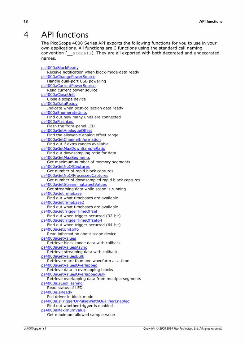
4 API functionsThe PicoScope 4000 Series API exports the following functions for you to use in yourown applications. All functions are C functions using the standard call namingconvention (__stdcall). They are all exported with both decorated and undecorated
names.
ps4000aBlockReadyReceive notification when block-mode data ready
ps4000aChangePowerSourceHandle dual-port USB powering
ps4000aCurrentPowerSourceRead current power source
ps4000aCloseUnitClose a scope device
ps4000aDataReadyIndicate when post-collection data ready
ps4000aEnumerateUnitsFind out how many units are connected
ps4000aFlashLedFlash the front-panel LED
ps4000aGetAnalogueOffsetFind the allowable analog offset range
ps4000aGetChannelInformationFind out if extra ranges available
ps4000aGetMaxDownSampleRatioFind out downsampling ratio for data
ps4000aGetMaxSegmentsGet maximum number of memory segments
ps4000aGetNoOfCapturesGet number of rapid block captures
ps4000aGetNoOfProcessedCapturesGet number of downsampled rapid block captures
ps4000aGetStreamingLatestValuesGet streaming data while scope is running
ps4000aGetTimebaseFind out what timebases are available
ps4000aGetTimebase2Find out what timebases are available
ps4000aGetTriggerTimeOffsetFind out when trigger occurred (32-bit)
ps4000aGetTriggerTimeOffset64Find out when trigger occurred (64-bit)
ps4000aGetUnitInfoRead information about scope device
ps4000aGetValuesRetrieve block-mode data with callback
ps4000aGetValuesAsyncRetrieve streaming data with callback
ps4000aGetValuesBulkRetrieve more than one waveform at a time
ps4000aGetValuesOverlappedRetrieve data in overlapping blocks
ps4000aGetValuesOverlappedBulkRetrieve overlapping data from multiple segments
ps4000aIsLedFlashingRead status of LED
ps4000aIsReadyPoll driver in block mode
ps4000aIsTriggerOrPulseWidthQualifierEnabledFind out whether trigger is enabled
ps4000aMaximumValueGet maximum allowed sample value
PicoScope 4000 Series (A API) Programmer's Guide 19
Copyright © 2008-2014 Pico Technology Ltd. All rights reserved. ps4000apg.en r1
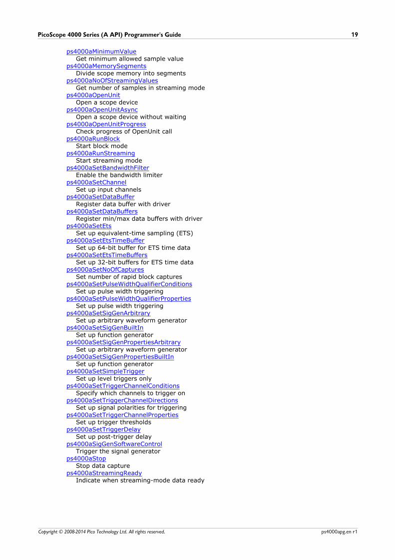
ps4000aMinimumValueGet minimum allowed sample value
ps4000aMemorySegmentsDivide scope memory into segments
ps4000aNoOfStreamingValuesGet number of samples in streaming mode
ps4000aOpenUnitOpen a scope device
ps4000aOpenUnitAsyncOpen a scope device without waiting
ps4000aOpenUnitProgressCheck progress of OpenUnit call
ps4000aRunBlockStart block mode
ps4000aRunStreamingStart streaming mode
ps4000aSetBandwidthFilterEnable the bandwidth limiter
ps4000aSetChannelSet up input channels
ps4000aSetDataBufferRegister data buffer with driver
ps4000aSetDataBuffersRegister min/max data buffers with driver
ps4000aSetEtsSet up equivalent-time sampling (ETS)
ps4000aSetEtsTimeBufferSet up 64-bit buffer for ETS time data
ps4000aSetEtsTimeBuffersSet up 32-bit buffers for ETS time data
ps4000aSetNoOfCapturesSet number of rapid block captures
ps4000aSetPulseWidthQualifierConditionsSet up pulse width triggering
ps4000aSetPulseWidthQualifierPropertiesSet up pulse width triggering
ps4000aSetSigGenArbitrarySet up arbitrary waveform generator
ps4000aSetSigGenBuiltInSet up function generator
ps4000aSetSigGenPropertiesArbitrarySet up arbitrary waveform generator
ps4000aSetSigGenPropertiesBuiltInSet up function generator
ps4000aSetSimpleTriggerSet up level triggers only
ps4000aSetTriggerChannelConditionsSpecify which channels to trigger on
ps4000aSetTriggerChannelDirectionsSet up signal polarities for triggering
ps4000aSetTriggerChannelPropertiesSet up trigger thresholds
ps4000aSetTriggerDelaySet up post-trigger delay
ps4000aSigGenSoftwareControlTrigger the signal generator
ps4000aStopStop data capture
ps4000aStreamingReadyIndicate when streaming-mode data ready
API functions20
Copyright © 2008-2014 Pico Technology Ltd. All rights reserved.ps4000apg.en r1
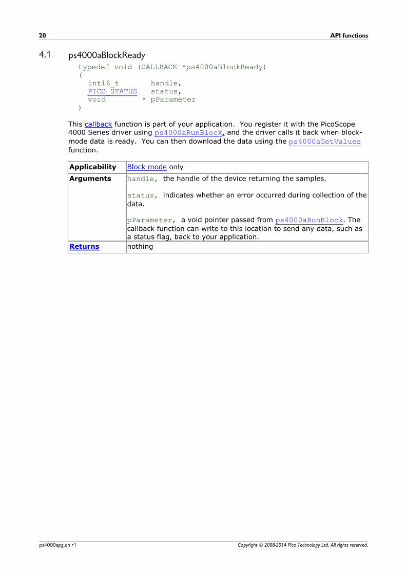
4.1 ps4000aBlockReadytypedef void (CALLBACK *ps4000aBlockReady)(
int16_t handle,PICO_STATUS status,void * pParameter
)
This callback function is part of your application. You register it with the PicoScope4000 Series driver using ps4000aRunBlock, and the driver calls it back when block-
mode data is ready. You can then download the data using the ps4000aGetValuesfunction.
Applicability Block mode only
Arguments handle, the handle of the device returning the samples.
status, indicates whether an error occurred during collection of the
data.
pParameter, a void pointer passed from ps4000aRunBlock. The
callback function can write to this location to send any data, such asa status flag, back to your application.
Returns nothing
PicoScope 4000 Series (A API) Programmer's Guide 21
Copyright © 2008-2014 Pico Technology Ltd. All rights reserved. ps4000apg.en r1
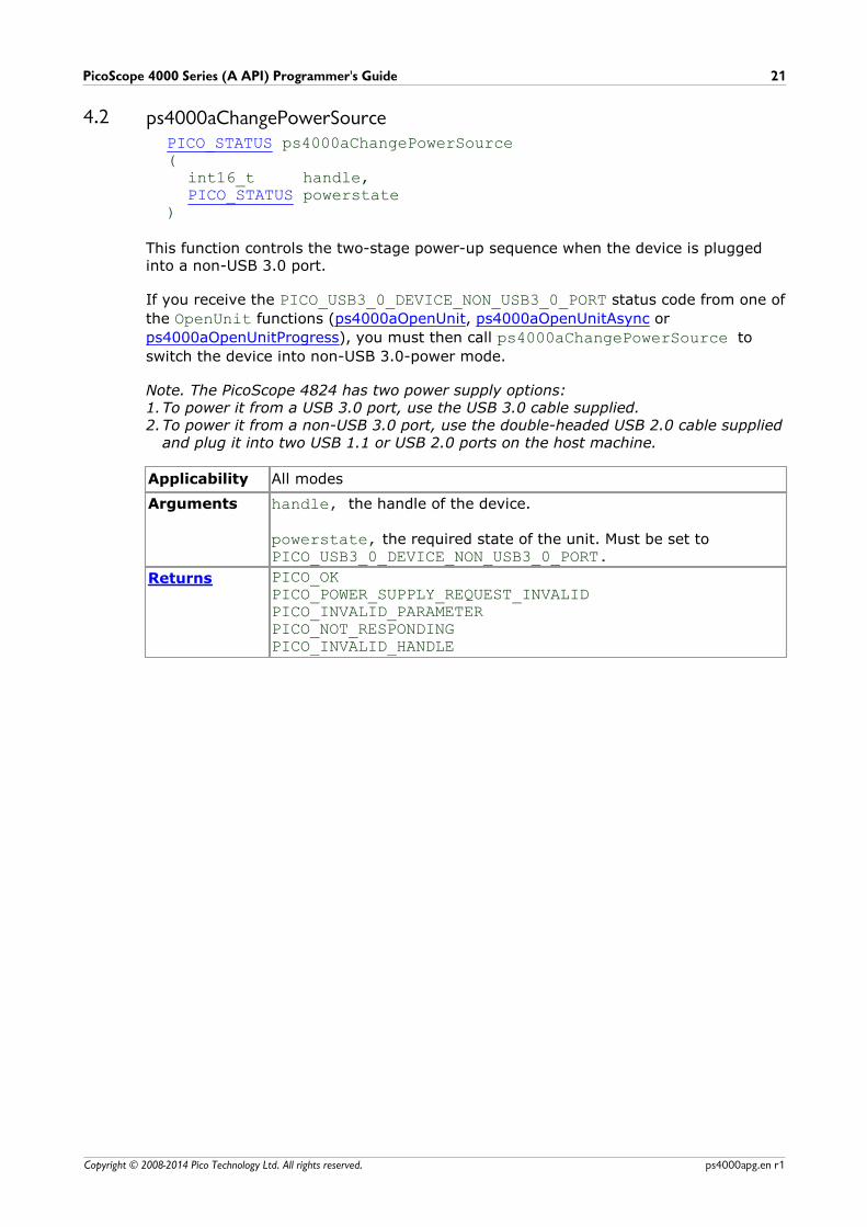
4.2 ps4000aChangePowerSourcePICO_STATUS ps4000aChangePowerSource(
int16_t handle,PICO_STATUS powerstate
)
This function controls the two-stage power-up sequence when the device is pluggedinto a non-USB 3.0 port.
If you receive the PICO_USB3_0_DEVICE_NON_USB3_0_PORT status code from one of
the OpenUnit functions (ps4000aOpenUnit, ps4000aOpenUnitAsync or
ps4000aOpenUnitProgress), you must then call ps4000aChangePowerSource to
switch the device into non-USB 3.0-power mode.
Note. The PicoScope 4824 has two power supply options:1.To power it from a USB 3.0 port, use the USB 3.0 cable supplied. 2.To power it from a non-USB 3.0 port, use the double-headed USB 2.0 cable supplied
and plug it into two USB 1.1 or USB 2.0 ports on the host machine.
Applicability All modes
Arguments handle, the handle of the device.
powerstate, the required state of the unit. Must be set toPICO_USB3_0_DEVICE_NON_USB3_0_PORT.
Returns PICO_OKPICO_POWER_SUPPLY_REQUEST_INVALIDPICO_INVALID_PARAMETERPICO_NOT_RESPONDINGPICO_INVALID_HANDLE

API functions22
Copyright © 2008-2014 Pico Technology Ltd. All rights reserved.ps4000apg.en r1
4.3 ps4000aCurrentPowerSourcePICO_STATUS ps4000aCurrentPowerSource(
int16_t handle)
This function returns the current power state of the device. There is no need to callthis function with the PicoScope 4824 as the device has only one possible state.
Applicability Reserved for future use
Arguments handle, the handle of the device
Returns PICO_OK
PicoScope 4000 Series (A API) Programmer's Guide 23
Copyright © 2008-2014 Pico Technology Ltd. All rights reserved. ps4000apg.en r1
4.4 ps4000aCloseUnitPICO_STATUS ps4000aCloseUnit(
int16_t handle)
This function shuts down a PicoScope 4000 scope device.
Applicability All modes
Arguments handle, the handle, returned by ps4000aOpenUnit, of the scope
device to be closed.
Returns PICO_OKPICO_HANDLE_INVALID

API functions24
Copyright © 2008-2014 Pico Technology Ltd. All rights reserved.ps4000apg.en r1
4.5 ps4000aDataReadytypedef void (CALLBACK *ps4000aDataReady)(
int16_t handle,PICO_STATUS status,uint32_t noOfSamples,int16_t overflow,void * pParameter
)
This function handles post-collection data returned by the driver after a call to ps4000aGetValuesAsync. It is a callback function that is part of your application.
You register it with the PicoScope 4000 Series driver using ps4000aGetValuesAsync, and the driver calls it back when the data is ready.
Applicability All modes
Arguments handle, the handle of the device returning the samples.
status, indicates success or failure
noOfSamples, the number of samples collected.
overflow, returns a flag that indicates whether an overvoltage has
occurred on any of the channels. It is a bit pattern with bit 0denoting Channel A.
pParameter, a void pointer passed from
ps4000aGetValuesAsync. The callback function can write to this
location to send any data, such as a status flag, back to theapplication. The data type is defined by the application programmer.
Returns nothing
PicoScope 4000 Series (A API) Programmer's Guide 25
Copyright © 2008-2014 Pico Technology Ltd. All rights reserved. ps4000apg.en r1
4.6 ps4000aEnumerateUnitsPICO_STATUS ps4000aEnumerateUnits(
int16_t * count,int8_t * serials,int16_t * serialLth
)
This function counts the number of PicoScope 4000 units connected to the computer,and returns a list of serial numbers as a string.
Applicability All modes
Arguments * count, on exit, the number of scopes found
* serials, on exit, a list of serial numbers separated by commas
and terminated by a final null. Example: AQ005/139,VDR61/356,ZOR14/107Can be NULL on entry if serial numbers are not required.
* serialLth, on entry, the length of the char buffer pointed to
by serials; on exit, the length of the string written to serials
Returns PICO_OKPICO_BUSYPICO_NULL_PARAMETERPICO_FW_FAILPICO_CONFIG_FAILPICO_MEMORY_FAILPICO_ANALOG_BOARDPICO_CONFIG_FAIL_AWGPICO_INITIALISE_FPGA
API functions26
Copyright © 2008-2014 Pico Technology Ltd. All rights reserved.ps4000apg.en r1
4.7 ps4000aFlashLedPICO_STATUS ps4000aFlashLed(
int16_t handle,int16_t start
)
This function flashes the LED on the front of the scope without blocking the callingthread. Calls to ps4000aRunStreaming and ps4000aRunBlock cancel any flashing
started by this function.
Applicability All modes
Arguments handle, the handle of the scope device
start, the action required: -
< 0 :flash the LED indefinitely.0 :stop the LED flashing.> 0 :flash the LED start times. If the LED is already flashing
on entry to this function, the flash count will be reset to start.
Returns PICO_OKPICO_HANDLE_INVALIDPICO_BUSY
PicoScope 4000 Series (A API) Programmer's Guide 27
Copyright © 2008-2014 Pico Technology Ltd. All rights reserved. ps4000apg.en r1
4.8 ps4000aGetAnalogueOffsetPICO_STATUS ps4000aGetAnalogueOffset(
int16_t handle,PS4000A_RANGE, range,PS4000A_COUPLING coupling,float * maximumVoltage,float * minimumVoltage
)
This function is used to get the maximum and minimum allowable analog offset for aspecific voltage range.
Applicability All modes
Arguments handle, the value returned from opening the device
range, the voltage range to be used when gathering the min and
max information
coupling, the type of AC/DC coupling used
* maximumVoltage, on exit, the maximum voltage allowed for the
range. Pointer may be NULL if not required.
* minimumVoltage, on exit, the minimum voltage allowed for the
range. Pointer may be NULL if not required. If both
maximumVoltage and minimumVoltage are NULL, the driver
returns PICO_NULL_PARAMETER.
Returns PICO_OK PICO_INVALID_HANDLEPICO_DRIVER_FUNCTIONPICO_INVALID_VOLTAGE_RANGEPICO_NULL_PARAMETER
API functions28
Copyright © 2008-2014 Pico Technology Ltd. All rights reserved.ps4000apg.en r1
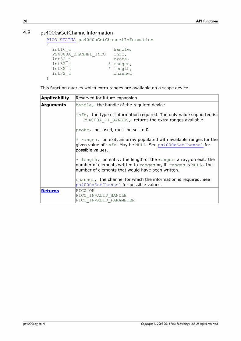
4.9 ps4000aGetChannelInformationPICO_STATUS ps4000aGetChannelInformation(
int16_t handle,PS4000A_CHANNEL_INFO info,int32_t probe,int32_t * ranges,int32_t * length,int32_t channel
)
This function queries which extra ranges are available on a scope device.
Applicability Reserved for future expansion
Arguments handle, the handle of the required device
info, the type of information required. The only value supported is:
PS4000A_CI_RANGES, returns the extra ranges available
probe, not used, must be set to 0
* ranges, on exit, an array populated with available ranges for the
given value of info. May be NULL. See ps4000aSetChannel for
possible values.
* length, on entry: the length of the ranges array; on exit: the
number of elements written to ranges or, if ranges is NULL, the
number of elements that would have been written.
channel, the channel for which the information is required. See
ps4000aSetChannel for possible values.
Returns PICO_OKPICO_INVALID_HANDLEPICO_INVALID_PARAMETER
PicoScope 4000 Series (A API) Programmer's Guide 29
Copyright © 2008-2014 Pico Technology Ltd. All rights reserved. ps4000apg.en r1
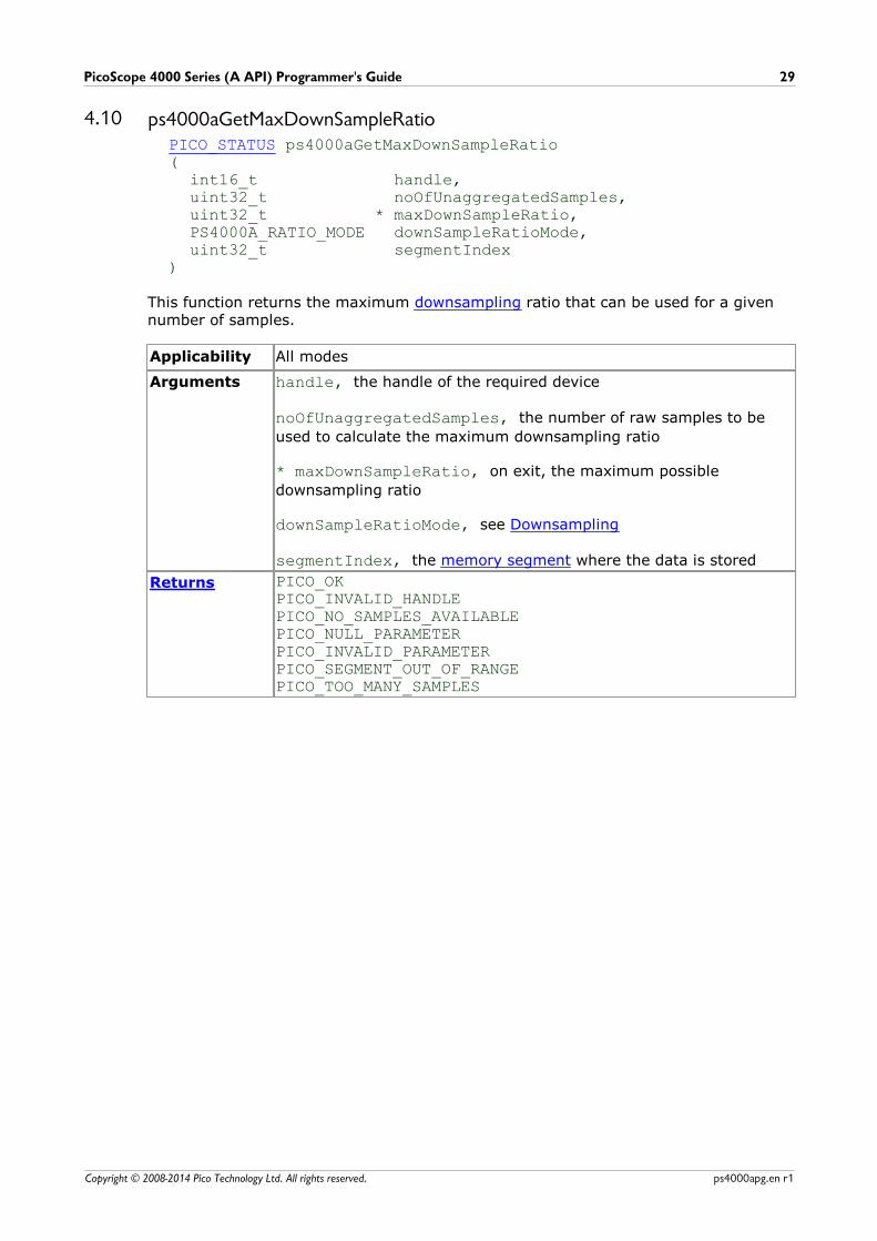
4.10 ps4000aGetMaxDownSampleRatioPICO_STATUS ps4000aGetMaxDownSampleRatio(
int16_t handle,uint32_t noOfUnaggregatedSamples,uint32_t * maxDownSampleRatio,PS4000A_RATIO_MODE downSampleRatioMode,uint32_t segmentIndex
)
This function returns the maximum downsampling ratio that can be used for a givennumber of samples.
Applicability All modes
Arguments handle, the handle of the required device
noOfUnaggregatedSamples, the number of raw samples to be
used to calculate the maximum downsampling ratio
* maxDownSampleRatio, on exit, the maximum possible
downsampling ratio
downSampleRatioMode, see Downsampling
segmentIndex, the memory segment where the data is stored
Returns PICO_OKPICO_INVALID_HANDLEPICO_NO_SAMPLES_AVAILABLEPICO_NULL_PARAMETERPICO_INVALID_PARAMETERPICO_SEGMENT_OUT_OF_RANGEPICO_TOO_MANY_SAMPLES
API functions30
Copyright © 2008-2014 Pico Technology Ltd. All rights reserved.ps4000apg.en r1
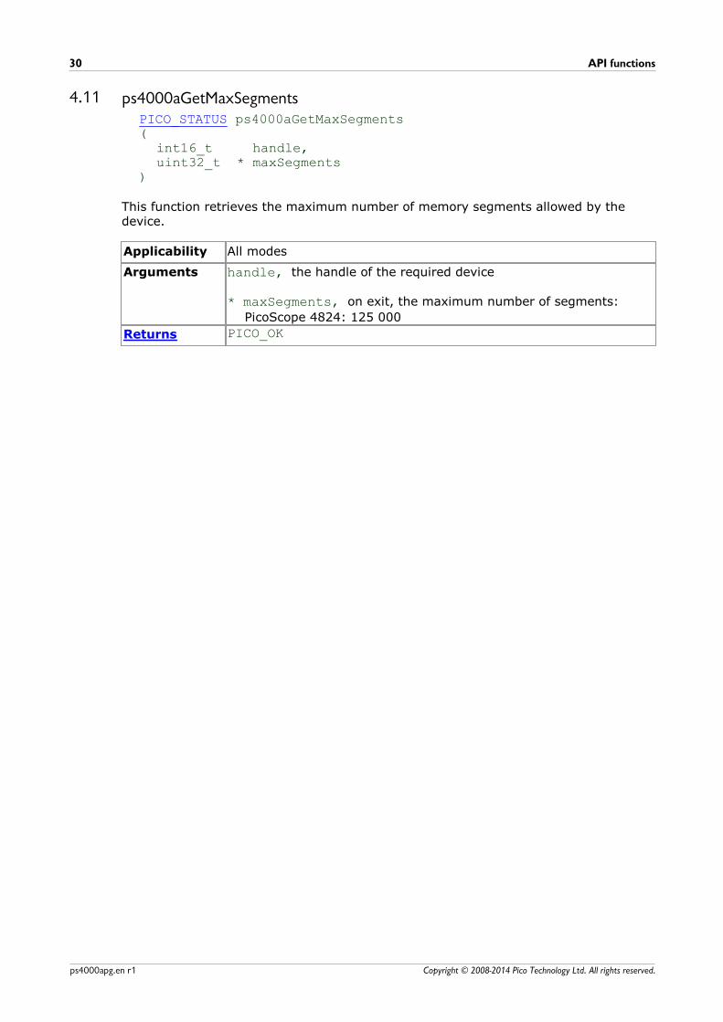
4.11 ps4000aGetMaxSegmentsPICO_STATUS ps4000aGetMaxSegments(
int16_t handle,uint32_t * maxSegments
)
This function retrieves the maximum number of memory segments allowed by thedevice.
Applicability All modes
Arguments handle, the handle of the required device
* maxSegments, on exit, the maximum number of segments:
PicoScope 4824: 125 000
Returns PICO_OK
PicoScope 4000 Series (A API) Programmer's Guide 31
Copyright © 2008-2014 Pico Technology Ltd. All rights reserved. ps4000apg.en r1
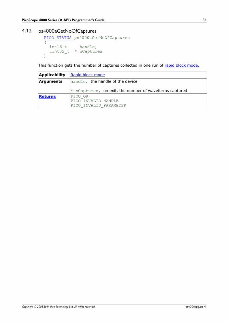
4.12 ps4000aGetNoOfCapturesPICO_STATUS ps4000aGetNoOfCaptures (
int16_t handle,uint32_t * nCaptures
)
This function gets the number of captures collected in one run of rapid block mode.
Applicability Rapid block mode
Arguments handle, the handle of the device
* nCaptures, on exit, the number of waveforms captured
Returns PICO_OKPICO_INVALID_HANDLEPICO_INVALID_PARAMETER
API functions32
Copyright © 2008-2014 Pico Technology Ltd. All rights reserved.ps4000apg.en r1
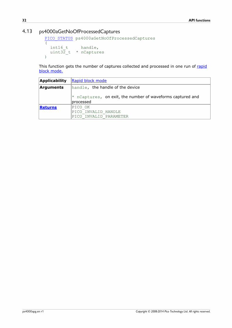
4.13 ps4000aGetNoOfProcessedCapturesPICO_STATUS ps4000aGetNoOfProcessedCaptures (
int16_t handle,uint32_t * nCaptures
)
This function gets the number of captures collected and processed in one run of rapidblock mode.
Applicability Rapid block mode
Arguments handle, the handle of the device
* nCaptures, on exit, the number of waveforms captured and
processed
Returns PICO_OKPICO_INVALID_HANDLEPICO_INVALID_PARAMETER

PicoScope 4000 Series (A API) Programmer's Guide 33
Copyright © 2008-2014 Pico Technology Ltd. All rights reserved. ps4000apg.en r1
4.14 ps4000aGetStreamingLatestValuesPICO_STATUS ps4000aGetStreamingLatestValues (
int16_t handle,ps4000aStreamingReady lpPs4000Ready,void * pParameter
)
This function is used to collect the next block of values while streaming is running. Youmust call ps4000aRunStreaming beforehand to set up streaming.
Applicability Streaming mode only
Arguments handle, the handle of the required device.
lpPs4000Ready, a pointer to your ps4000aStreamingReadycallback function that will return the latest downsampled values.
pParameter, a void pointer that will be passed to the
ps4000aStreamingReady callback function.
Returns PICO_OKPICO_INVALID_HANDLEPICO_NO_SAMPLES_AVAILABLEPICO_INVALID_CALLPICO_BUSYPICO_NOT_RESPONDING
API functions34
Copyright © 2008-2014 Pico Technology Ltd. All rights reserved.ps4000apg.en r1
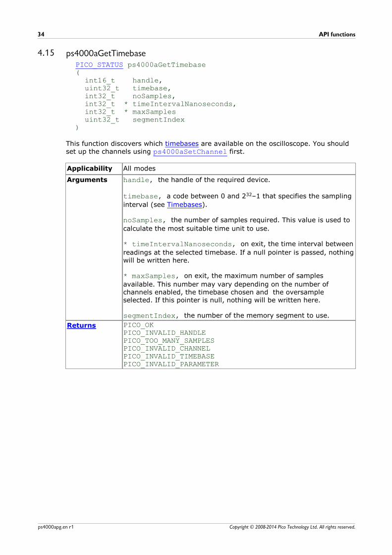
4.15 ps4000aGetTimebasePICO_STATUS ps4000aGetTimebase (
int16_t handle,uint32_t timebase,int32_t noSamples,int32_t * timeIntervalNanoseconds,int32_t * maxSamplesuint32_t segmentIndex
)
This function discovers which timebases are available on the oscilloscope. You shouldset up the channels using ps4000aSetChannel first.
Applicability All modes
Arguments handle, the handle of the required device.
timebase, a code between 0 and 232–1 that specifies the sampling
interval (see Timebases).
noSamples, the number of samples required. This value is used to
calculate the most suitable time unit to use.
* timeIntervalNanoseconds, on exit, the time interval between
readings at the selected timebase. If a null pointer is passed, nothingwill be written here.
* maxSamples, on exit, the maximum number of samples
available. This number may vary depending on the number ofchannels enabled, the timebase chosen and the oversampleselected. If this pointer is null, nothing will be written here.
segmentIndex, the number of the memory segment to use.
Returns PICO_OKPICO_INVALID_HANDLEPICO_TOO_MANY_SAMPLESPICO_INVALID_CHANNELPICO_INVALID_TIMEBASEPICO_INVALID_PARAMETER

PicoScope 4000 Series (A API) Programmer's Guide 35
Copyright © 2008-2014 Pico Technology Ltd. All rights reserved. ps4000apg.en r1
4.16 ps4000aGetTimebase2PICO_STATUS ps4000aGetTimebase2 (
int16_t handle,uint32_t timebase,int32_t noSamples,float * timeIntervalNanoseconds,int32_t * maxSamples,uint32_t segmentIndex
)
This function differs from ps4000aGetTimebase only in the type of the
timeIntervalNanoseconds argument.
Applicability All modes
Arguments * timeIntervalNanoseconds, on exit, the time interval between
readings at the selected timebase. If a null pointer is passed, nothingwill be written here.
All others as in ps4000aGetTimebase.
Returns See ps4000aGetTimebase.
API functions36
Copyright © 2008-2014 Pico Technology Ltd. All rights reserved.ps4000apg.en r1
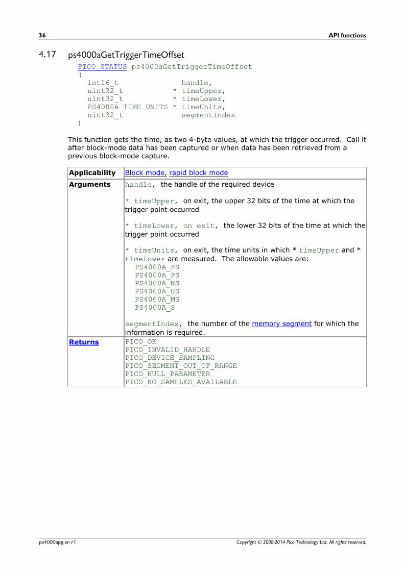
4.17 ps4000aGetTriggerTimeOffsetPICO_STATUS ps4000aGetTriggerTimeOffset(
int16_t handle,uint32_t * timeUpper,uint32_t * timeLower,PS4000A_TIME_UNITS * timeUnits,uint32_t segmentIndex
)
This function gets the time, as two 4-byte values, at which the trigger occurred. Call itafter block-mode data has been captured or when data has been retrieved from aprevious block-mode capture.
Applicability Block mode, rapid block mode
Arguments handle, the handle of the required device
* timeUpper, on exit, the upper 32 bits of the time at which the
trigger point occurred
* timeLower, on exit, the lower 32 bits of the time at which the
trigger point occurred
* timeUnits, on exit, the time units in which * timeUpper and *
timeLower are measured. The allowable values are:PS4000A_FSPS4000A_PSPS4000A_NSPS4000A_USPS4000A_MSPS4000A_S
segmentIndex, the number of the memory segment for which the
information is required.
Returns PICO_OKPICO_INVALID_HANDLEPICO_DEVICE_SAMPLINGPICO_SEGMENT_OUT_OF_RANGEPICO_NULL_PARAMETERPICO_NO_SAMPLES_AVAILABLE
PicoScope 4000 Series (A API) Programmer's Guide 37
Copyright © 2008-2014 Pico Technology Ltd. All rights reserved. ps4000apg.en r1
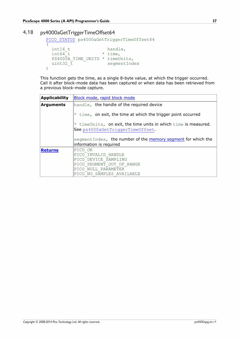
4.18 ps4000aGetTriggerTimeOffset64PICO_STATUS ps4000aGetTriggerTimeOffset64(
int16_t handle,int64_t * time,PS4000A_TIME_UNITS * timeUnits,uint32_t segmentIndex
)
This function gets the time, as a single 8-byte value, at which the trigger occurred. Call it after block-mode data has been captured or when data has been retrieved froma previous block-mode capture.
Applicability Block mode, rapid block mode
Arguments handle, the handle of the required device
* time, on exit, the time at which the trigger point occurred
* timeUnits, on exit, the time units in which time is measured.
See ps4000aGetTriggerTimeOffset.
segmentIndex, the number of the memory segment for which the
information is required
Returns PICO_OKPICO_INVALID_HANDLEPICO_DEVICE_SAMPLINGPICO_SEGMENT_OUT_OF_RANGEPICO_NULL_PARAMETERPICO_NO_SAMPLES_AVAILABLE
API functions38
Copyright © 2008-2014 Pico Technology Ltd. All rights reserved.ps4000apg.en r1
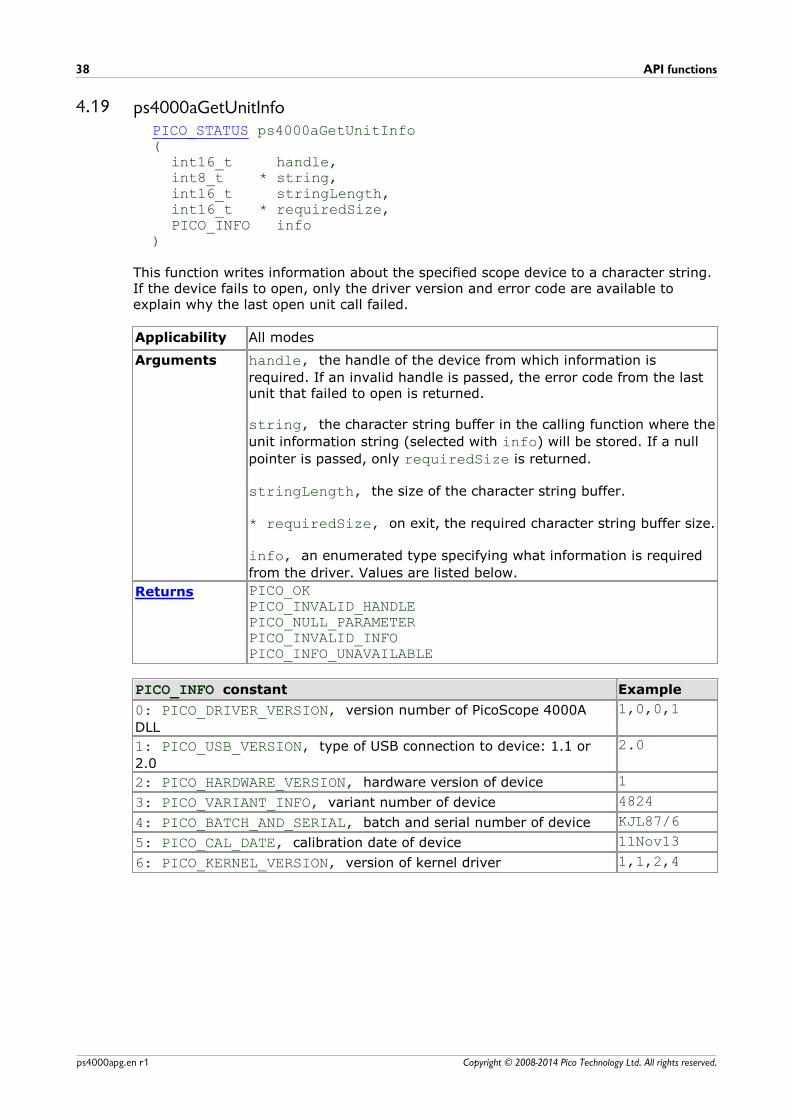
4.19 ps4000aGetUnitInfoPICO_STATUS ps4000aGetUnitInfo (
int16_t handle, int8_t * string,int16_t stringLength,int16_t * requiredSize,PICO_INFO info
)
This function writes information about the specified scope device to a character string.If the device fails to open, only the driver version and error code are available toexplain why the last open unit call failed.
Applicability All modes
Arguments handle, the handle of the device from which information is
required. If an invalid handle is passed, the error code from the lastunit that failed to open is returned.
string, the character string buffer in the calling function where the
unit information string (selected with info) will be stored. If a null
pointer is passed, only requiredSize is returned.
stringLength, the size of the character string buffer.
* requiredSize, on exit, the required character string buffer size.
info, an enumerated type specifying what information is required
from the driver. Values are listed below.
Returns PICO_OKPICO_INVALID_HANDLEPICO_NULL_PARAMETERPICO_INVALID_INFOPICO_INFO_UNAVAILABLE
PICO_INFO constant Example
0: PICO_DRIVER_VERSION, version number of PicoScope 4000A
DLL
1,0,0,1
1: PICO_USB_VERSION, type of USB connection to device: 1.1 or
2.0
2.0
2: PICO_HARDWARE_VERSION, hardware version of device 1
3: PICO_VARIANT_INFO, variant number of device 4824
4: PICO_BATCH_AND_SERIAL, batch and serial number of device KJL87/6
5: PICO_CAL_DATE, calibration date of device 11Nov13
6: PICO_KERNEL_VERSION, version of kernel driver 1,1,2,4
PicoScope 4000 Series (A API) Programmer's Guide 39
Copyright © 2008-2014 Pico Technology Ltd. All rights reserved. ps4000apg.en r1
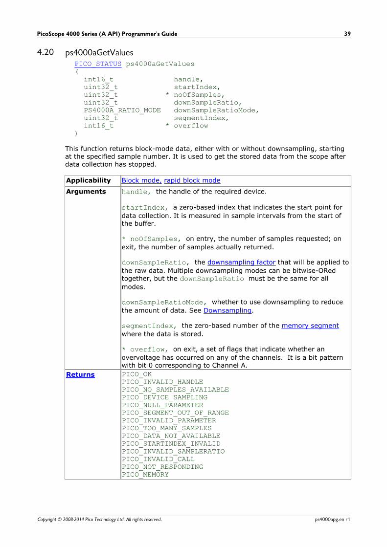
4.20 ps4000aGetValuesPICO_STATUS ps4000aGetValues(
int16_t handle,uint32_t startIndex,uint32_t * noOfSamples,uint32_t downSampleRatio,PS4000A_RATIO_MODE downSampleRatioMode,uint32_t segmentIndex,int16_t * overflow
)
This function returns block-mode data, either with or without downsampling, startingat the specified sample number. It is used to get the stored data from the scope afterdata collection has stopped.
Applicability Block mode, rapid block mode
Arguments handle, the handle of the required device.
startIndex, a zero-based index that indicates the start point for
data collection. It is measured in sample intervals from the start ofthe buffer.
* noOfSamples, on entry, the number of samples requested; on
exit, the number of samples actually returned.
downSampleRatio, the downsampling factor that will be applied to
the raw data. Multiple downsampling modes can be bitwise-ORedtogether, but the downSampleRatio must be the same for all
modes.
downSampleRatioMode, whether to use downsampling to reduce
the amount of data. See Downsampling.
segmentIndex, the zero-based number of the memory segment
where the data is stored.
* overflow, on exit, a set of flags that indicate whether an
overvoltage has occurred on any of the channels. It is a bit patternwith bit 0 corresponding to Channel A.
Returns PICO_OKPICO_INVALID_HANDLEPICO_NO_SAMPLES_AVAILABLEPICO_DEVICE_SAMPLINGPICO_NULL_PARAMETERPICO_SEGMENT_OUT_OF_RANGEPICO_INVALID_PARAMETERPICO_TOO_MANY_SAMPLESPICO_DATA_NOT_AVAILABLEPICO_STARTINDEX_INVALIDPICO_INVALID_SAMPLERATIOPICO_INVALID_CALLPICO_NOT_RESPONDINGPICO_MEMORY
API functions40
Copyright © 2008-2014 Pico Technology Ltd. All rights reserved.ps4000apg.en r1
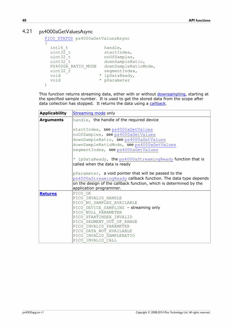
4.21 ps4000aGetValuesAsyncPICO_STATUS ps4000aGetValuesAsync(
int16_t handle,uint32_t startIndex,uint32_t noOfSamples,uint32_t downSampleRatio,PS4000A_RATIO_MODE downSampleRatioMode,uint32_t segmentIndex,void * lpDataReady,void * pParameter
)
This function returns streaming data, either with or without downsampling, starting atthe specified sample number. It is used to get the stored data from the scope afterdata collection has stopped. It returns the data using a callback.
Applicability Streaming mode only
Arguments handle, the handle of the required device
startIndex, see ps4000aGetValuesnoOfSamples, see ps4000aGetValuesdownSampleRatio, see ps4000aGetValuesdownSampleRatioMode, see ps4000aGetValuessegmentIndex, see ps4000aGetValues
* lpDataReady, the ps4000aStreamingReady function that is
called when the data is ready
pParameter, a void pointer that will be passed to the
ps4000aStreamingReady callback function. The data type depends
on the design of the callback function, which is determined by theapplication programmer.
Returns PICO_OKPICO_INVALID_HANDLEPICO_NO_SAMPLES_AVAILABLEPICO_DEVICE_SAMPLING – streaming onlyPICO_NULL_PARAMETERPICO_STARTINDEX_INVALIDPICO_SEGMENT_OUT_OF_RANGEPICO_INVALID_PARAMETERPICO_DATA_NOT_AVAILABLEPICO_INVALID_SAMPLERATIOPICO_INVALID_CALL
PicoScope 4000 Series (A API) Programmer's Guide 41
Copyright © 2008-2014 Pico Technology Ltd. All rights reserved. ps4000apg.en r1
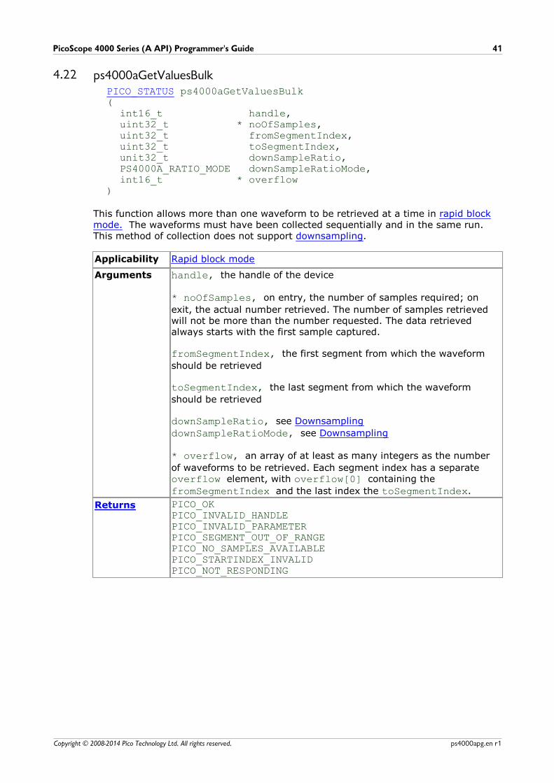
4.22 ps4000aGetValuesBulkPICO_STATUS ps4000aGetValuesBulk(
int16_t handle,uint32_t * noOfSamples,uint32_t fromSegmentIndex,uint32_t toSegmentIndex,unit32_t downSampleRatio,PS4000A_RATIO_MODE downSampleRatioMode,int16_t * overflow
)
This function allows more than one waveform to be retrieved at a time in rapid blockmode. The waveforms must have been collected sequentially and in the same run.This method of collection does not support downsampling.
Applicability Rapid block mode
Arguments handle, the handle of the device
* noOfSamples, on entry, the number of samples required; on
exit, the actual number retrieved. The number of samples retrievedwill not be more than the number requested. The data retrievedalways starts with the first sample captured.
fromSegmentIndex, the first segment from which the waveform
should be retrieved
toSegmentIndex, the last segment from which the waveform
should be retrieved
downSampleRatio, see Downsampling
downSampleRatioMode, see Downsampling
* overflow, an array of at least as many integers as the number
of waveforms to be retrieved. Each segment index has a separate overflow element, with overflow[0] containing the
fromSegmentIndex and the last index the toSegmentIndex.
Returns PICO_OKPICO_INVALID_HANDLEPICO_INVALID_PARAMETERPICO_SEGMENT_OUT_OF_RANGEPICO_NO_SAMPLES_AVAILABLEPICO_STARTINDEX_INVALIDPICO_NOT_RESPONDING
API functions42
Copyright © 2008-2014 Pico Technology Ltd. All rights reserved.ps4000apg.en r1
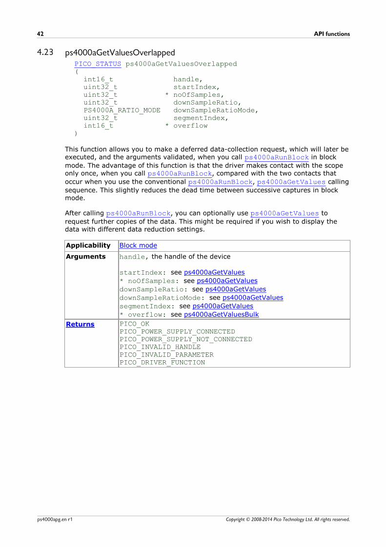
4.23 ps4000aGetValuesOverlappedPICO_STATUS ps4000aGetValuesOverlapped(
int16_t handle,uint32_t startIndex,uint32_t * noOfSamples,uint32_t downSampleRatio,PS4000A_RATIO_MODE downSampleRatioMode,uint32_t segmentIndex,int16_t * overflow
)
This function allows you to make a deferred data-collection request, which will later beexecuted, and the arguments validated, when you call ps4000aRunBlock in block
mode. The advantage of this function is that the driver makes contact with the scopeonly once, when you call ps4000aRunBlock, compared with the two contacts that
occur when you use the conventional ps4000aRunBlock, ps4000aGetValues calling
sequence. This slightly reduces the dead time between successive captures in blockmode.
After calling ps4000aRunBlock, you can optionally use ps4000aGetValues to
request further copies of the data. This might be required if you wish to display thedata with different data reduction settings.
Applicability Block mode
Arguments handle, the handle of the device
startIndex: see ps4000aGetValues
* noOfSamples: see ps4000aGetValues
downSampleRatio: see ps4000aGetValues
downSampleRatioMode: see ps4000aGetValues
segmentIndex: see ps4000aGetValues
* overflow: see ps4000aGetValuesBulk
Returns PICO_OKPICO_POWER_SUPPLY_CONNECTEDPICO_POWER_SUPPLY_NOT_CONNECTEDPICO_INVALID_HANDLEPICO_INVALID_PARAMETERPICO_DRIVER_FUNCTION
PicoScope 4000 Series (A API) Programmer's Guide 43
Copyright © 2008-2014 Pico Technology Ltd. All rights reserved. ps4000apg.en r1
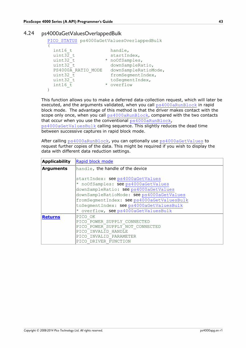
4.24 ps4000aGetValuesOverlappedBulkPICO_STATUS ps4000aGetValuesOverlappedBulk(
int16_t handle,uint32_t startIndex,uint32_t * noOfSamples,uint32_t downSampleRatio,PS4000A_RATIO_MODE downSampleRatioMode,uint32_t fromSegmentIndex,uint32_t toSegmentIndex,int16_t * overflow
)
This function allows you to make a deferred data-collection request, which will later beexecuted, and the arguments validated, when you call ps4000aRunBlock in rapid
block mode. The advantage of this method is that the driver makes contact with thescope only once, when you call ps4000aRunBlock, compared with the two contacts
that occur when you use the conventional ps4000aRunBlock,
ps4000aGetValuesBulk calling sequence. This slightly reduces the dead time
between successive captures in rapid block mode.
After calling ps4000aRunBlock, you can optionally use ps4000aGetValues to
request further copies of the data. This might be required if you wish to display thedata with different data reduction settings.
Applicability Rapid block mode
Arguments handle, the handle of the device
startIndex: see ps4000aGetValues* noOfSamples: see ps4000aGetValuesdownSampleRatio: see ps4000aGetValuesdownSampleRatioMode: see ps4000aGetValuesfromSegmentIndex: see ps4000aGetValuesBulktoSegmentIndex: see ps4000aGetValuesBulk* overflow, see ps4000aGetValuesBulk
Returns PICO_OKPICO_POWER_SUPPLY_CONNECTEDPICO_POWER_SUPPLY_NOT_CONNECTEDPICO_INVALID_HANDLEPICO_INVALID_PARAMETERPICO_DRIVER_FUNCTION
API functions44
Copyright © 2008-2014 Pico Technology Ltd. All rights reserved.ps4000apg.en r1
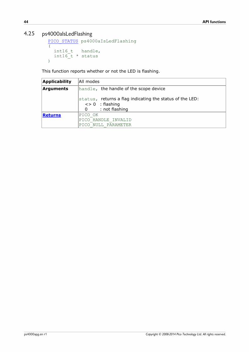
4.25 ps4000aIsLedFlashingPICO_STATUS ps4000aIsLedFlashing(
int16_t handle,int16_t * status
)
This function reports whether or not the LED is flashing.
Applicability All modes
Arguments handle, the handle of the scope device
status, returns a flag indicating the status of the LED:
<> 0 : flashing0 : not flashing
Returns PICO_OKPICO_HANDLE_INVALIDPICO_NULL_PARAMETER
PicoScope 4000 Series (A API) Programmer's Guide 45
Copyright © 2008-2014 Pico Technology Ltd. All rights reserved. ps4000apg.en r1
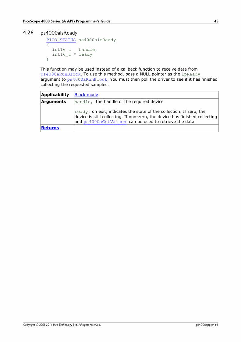
4.26 ps4000aIsReadyPICO_STATUS ps4000aIsReady(
int16_t handle,int16_t * ready
)
This function may be used instead of a callback function to receive data from ps4000aRunBlock. To use this method, pass a NULL pointer as the lpReadyargument to ps4000aRunBlock. You must then poll the driver to see if it has finished
collecting the requested samples.
Applicability Block mode
Arguments handle, the handle of the required device
ready, on exit, indicates the state of the collection. If zero, the
device is still collecting. If non-zero, the device has finished collectingand ps4000aGetValues can be used to retrieve the data.
Returns
API functions46
Copyright © 2008-2014 Pico Technology Ltd. All rights reserved.ps4000apg.en r1
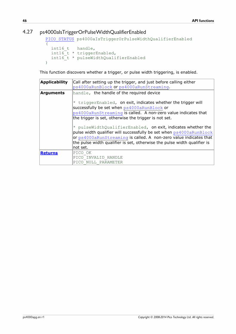
4.27 ps4000aIsTriggerOrPulseWidthQualifierEnabledPICO_STATUS ps4000aIsTriggerOrPulseWidthQualifierEnabled(
int16_t handle,int16_t * triggerEnabled,int16_t * pulseWidthQualifierEnabled
)
This function discovers whether a trigger, or pulse width triggering, is enabled.
Applicability Call after setting up the trigger, and just before calling either ps4000aRunBlock or ps4000aRunStreaming.
Arguments handle, the handle of the required device
* triggerEnabled, on exit, indicates whether the trigger will
successfully be set when ps4000aRunBlock or
ps4000aRunStreaming is called. A non-zero value indicates that
the trigger is set, otherwise the trigger is not set.
* pulseWidthQualifierEnabled, on exit, indicates whether the
pulse width qualifier will successfully be set when ps4000aRunBlockor ps4000aRunStreaming is called. A non-zero value indicates that
the pulse width qualifier is set, otherwise the pulse width qualifier isnot set.
Returns PICO_OKPICO_INVALID_HANDLEPICO_NULL_PARAMETER
PicoScope 4000 Series (A API) Programmer's Guide 47
Copyright © 2008-2014 Pico Technology Ltd. All rights reserved. ps4000apg.en r1
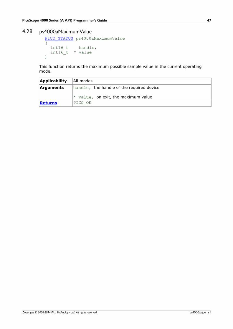
4.28 ps4000aMaximumValuePICO_STATUS ps4000aMaximumValue(
int16_t handle,int16_t * value
)
This function returns the maximum possible sample value in the current operatingmode.
Applicability All modes
Arguments handle, the handle of the required device
* value, on exit, the maximum value
Returns PICO_OK

API functions48
Copyright © 2008-2014 Pico Technology Ltd. All rights reserved.ps4000apg.en r1
4.29 ps4000aMinimumValuePICO_STATUS ps4000aMinimumValue(
int16_t handle,int16_t * value
)
This function returns the minimum possible sample value in the current operatingmode.
Applicability All modes
Arguments handle, the handle of the required device
* value, on exit, the minimum value
Returns PICO_OK

PicoScope 4000 Series (A API) Programmer's Guide 49
Copyright © 2008-2014 Pico Technology Ltd. All rights reserved. ps4000apg.en r1
4.30 ps4000aMemorySegmentsPICO_STATUS ps4000aMemorySegments(
int16_t handle,uint32_t nSegments,int32_t * nMaxSamples
)
This function sets the number of memory segments that the scope device will use.
By default, each capture fills the scope device's available memory. This functionallows you to divide the memory into a number of segments so that the scope canstore several captures sequentially. The number of segments defaults to 1 when thescope device is opened.
Applicability All modes
Arguments handle, the handle of the required device
nSegments, the number of segments to be used, from 1 to the
number returned by ps4000aGetMaxSegments.
* nMaxSamples, on exit, the number of samples that are available
in each segment. This is independent of the number of channels, so ifmore than one channel is in use then the number of samplesavailable to each channel is nMaxSamples divided by the number of
channels.
Returns PICO_OKPICO_USER_CALLBACKPICO_INVALID_HANDLEPICO_TOO_MANY_SEGMENTSPICO_MEMORY
API functions50
Copyright © 2008-2014 Pico Technology Ltd. All rights reserved.ps4000apg.en r1
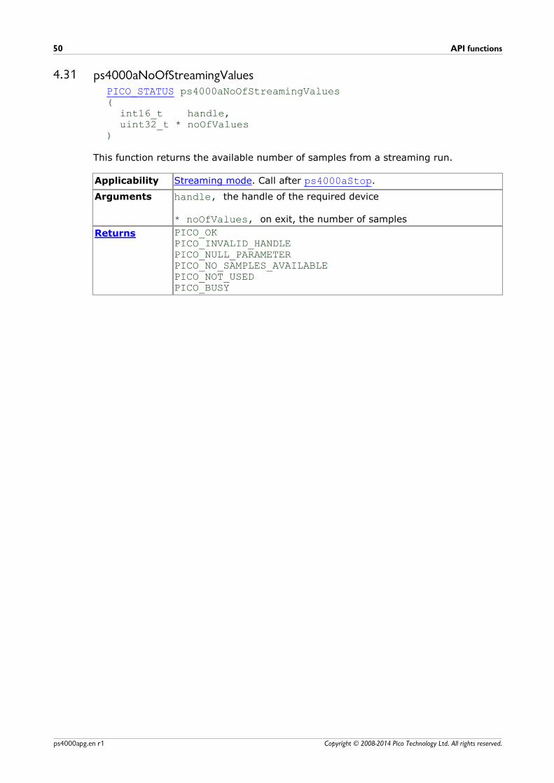
4.31 ps4000aNoOfStreamingValuesPICO_STATUS ps4000aNoOfStreamingValues (
int16_t handle,uint32_t * noOfValues
)
This function returns the available number of samples from a streaming run.
Applicability Streaming mode. Call after ps4000aStop.
Arguments handle, the handle of the required device
* noOfValues, on exit, the number of samples
Returns PICO_OKPICO_INVALID_HANDLEPICO_NULL_PARAMETERPICO_NO_SAMPLES_AVAILABLEPICO_NOT_USEDPICO_BUSY

PicoScope 4000 Series (A API) Programmer's Guide 51
Copyright © 2008-2014 Pico Technology Ltd. All rights reserved. ps4000apg.en r1
4.32 ps4000aOpenUnitPICO_STATUS ps4000aOpenUnit (
int16_t * handle,int8_t * serial
)
This function opens a scope device. The maximum number of units that can be openedis determined by the operating system, the kernel driver and the PC's hardware.
Applicability All modes
Arguments handle, on exit, the handle of the device:
-1 : if the unit fails to open,0 : if no unit is found or> 0 : if successful (value is handle of the device opened)
The handle must be used in all subsequent calls to API functions toidentify this scope device.
* serial, on exit, a null-terminated string containing the device's
serial number.
Returns PICO_OKPICO_OS_NOT_SUPPORTEDPICO_OPEN_OPERATION_IN_PROGRESSPICO_EEPROM_CORRUPTPICO_KERNEL_DRIVER_TOO_OLDPICO_FW_FAILPICO_MAX_UNITS_OPENEDPICO_NOT_FOUNDPICO_NOT_RESPONDINGPICO_USB3_0_DEVICE_NON_USB3_0_PORT
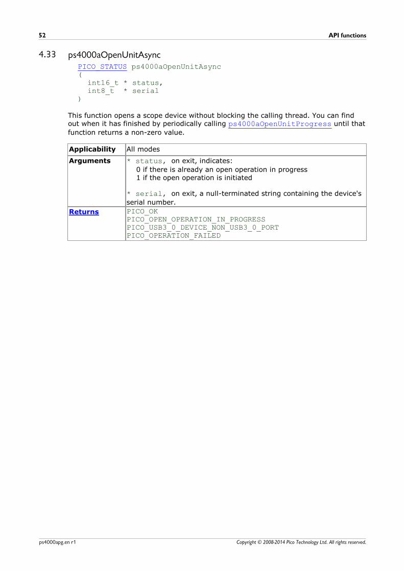
API functions52
Copyright © 2008-2014 Pico Technology Ltd. All rights reserved.ps4000apg.en r1
4.33 ps4000aOpenUnitAsyncPICO_STATUS ps4000aOpenUnitAsync(
int16_t * status,int8_t * serial
)
This function opens a scope device without blocking the calling thread. You can findout when it has finished by periodically calling ps4000aOpenUnitProgress until that
function returns a non-zero value.
Applicability All modes
Arguments * status, on exit, indicates:
0 if there is already an open operation in progress1 if the open operation is initiated
* serial, on exit, a null-terminated string containing the device's
serial number.
Returns PICO_OKPICO_OPEN_OPERATION_IN_PROGRESSPICO_USB3_0_DEVICE_NON_USB3_0_PORTPICO_OPERATION_FAILED

PicoScope 4000 Series (A API) Programmer's Guide 53
Copyright © 2008-2014 Pico Technology Ltd. All rights reserved. ps4000apg.en r1
4.34 ps4000aOpenUnitProgressPICO_STATUS ps4000aOpenUnitProgress(
int16_t * handle,int16_t * progressPercent,int16_t * complete
)
This function checks on the progress of ps4000aOpenUnitAsync.
Applicability Use after ps4000aOpenUnitAsync
Arguments * handle, on exit, the unit handle. -1 if the unit fails to open, 0 if
no unit is found or a non-zero handle to the device. This handle isvalid only if the function returns PICO_OK.
* progressPercent, on exit, the percentage progress. 100%
implies that the open operation is complete.
* complete, on exit, set to 1 when the open operation has
finished
Returns PICO_OKPICO_NULL_PARAMETERPICO_OPERATION_FAILEDPICO_USB3_0_DEVICE_NON_USB3_0_PORT
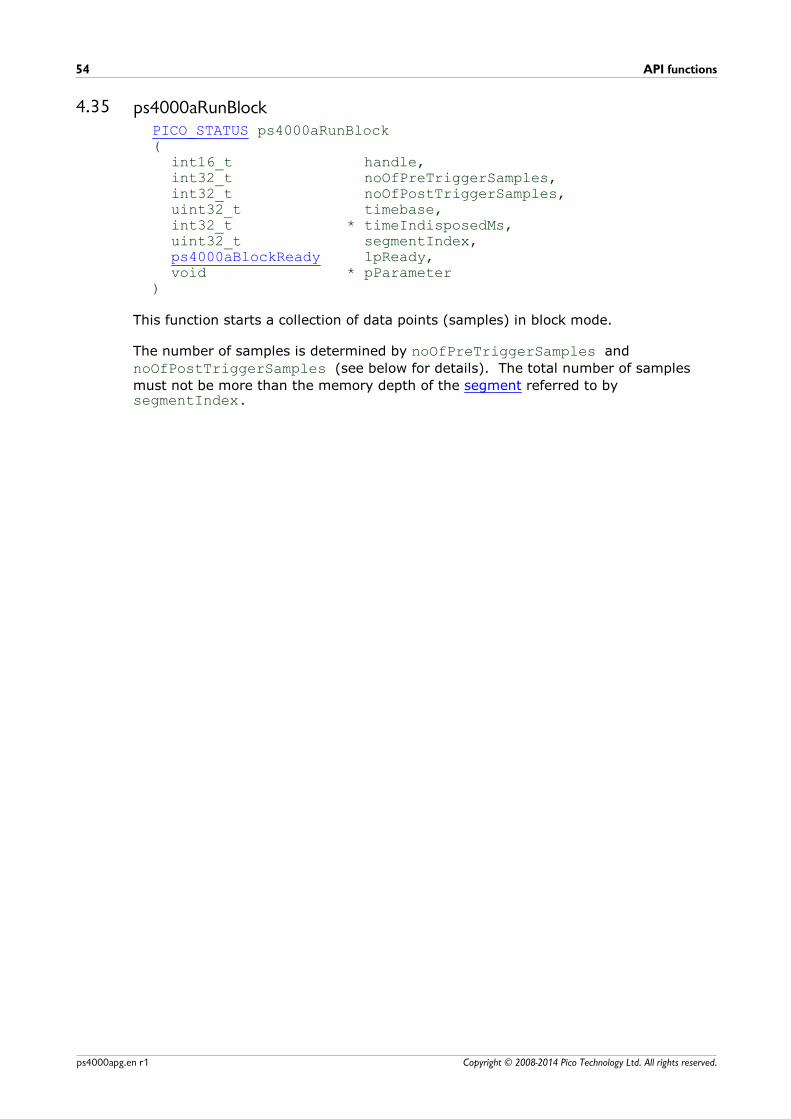
API functions54
Copyright © 2008-2014 Pico Technology Ltd. All rights reserved.ps4000apg.en r1
4.35 ps4000aRunBlockPICO_STATUS ps4000aRunBlock (
int16_t handle,int32_t noOfPreTriggerSamples,int32_t noOfPostTriggerSamples,uint32_t timebase,int32_t * timeIndisposedMs,uint32_t segmentIndex,ps4000aBlockReady lpReady,void * pParameter
)
This function starts a collection of data points (samples) in block mode.
The number of samples is determined by noOfPreTriggerSamples and
noOfPostTriggerSamples (see below for details). The total number of samples
must not be more than the memory depth of the segment referred to bysegmentIndex.
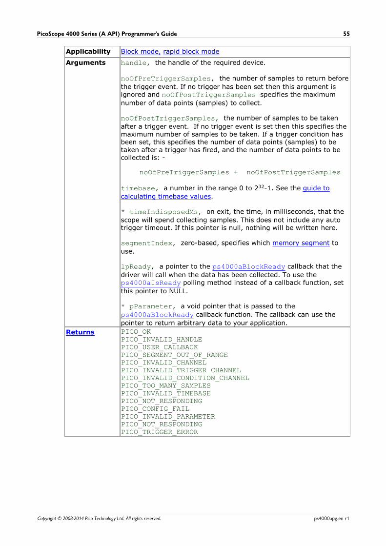
PicoScope 4000 Series (A API) Programmer's Guide 55
Copyright © 2008-2014 Pico Technology Ltd. All rights reserved. ps4000apg.en r1
Applicability Block mode, rapid block mode
Arguments handle, the handle of the required device.
noOfPreTriggerSamples, the number of samples to return before
the trigger event. If no trigger has been set then this argument isignored and noOfPostTriggerSamples specifies the maximum
number of data points (samples) to collect.
noOfPostTriggerSamples, the number of samples to be taken
after a trigger event. If no trigger event is set then this specifies themaximum number of samples to be taken. If a trigger condition hasbeen set, this specifies the number of data points (samples) to betaken after a trigger has fired, and the number of data points to becollected is: -
noOfPreTriggerSamples + noOfPostTriggerSamples
timebase, a number in the range 0 to 232-1. See the guide to
calculating timebase values.
* timeIndisposedMs, on exit, the time, in milliseconds, that the
scope will spend collecting samples. This does not include any autotrigger timeout. If this pointer is null, nothing will be written here.
segmentIndex, zero-based, specifies which memory segment to
use.
lpReady, a pointer to the ps4000aBlockReady callback that the
driver will call when the data has been collected. To use the ps4000aIsReady polling method instead of a callback function, set
this pointer to NULL.
* pParameter, a void pointer that is passed to the
ps4000aBlockReady callback function. The callback can use the
pointer to return arbitrary data to your application.
Returns PICO_OKPICO_INVALID_HANDLEPICO_USER_CALLBACKPICO_SEGMENT_OUT_OF_RANGEPICO_INVALID_CHANNELPICO_INVALID_TRIGGER_CHANNELPICO_INVALID_CONDITION_CHANNELPICO_TOO_MANY_SAMPLESPICO_INVALID_TIMEBASEPICO_NOT_RESPONDINGPICO_CONFIG_FAILPICO_INVALID_PARAMETERPICO_NOT_RESPONDINGPICO_TRIGGER_ERROR

API functions56
Copyright © 2008-2014 Pico Technology Ltd. All rights reserved.ps4000apg.en r1
4.36 ps4000aRunStreamingPICO_STATUS ps4000aRunStreaming (
int16_t handle, uint32_t * sampleInterval, PS4000A_TIME_UNITS sampleIntervalTimeUnits,uint32_t maxPreTriggerSamples,uint32_t maxPostTriggerSamples,int16_t autoStop,uint32_t downSampleRatio,PS4000A_RATIO_MODE downSampleRatioMode,uint32_t overviewBufferSize
)
This function tells the oscilloscope to start collecting data in streaming mode. Whendata has been collected from the device it is downsampled and the values returned tothe application. Call ps4000aGetStreamingLatestValues to retrieve the data.
When a trigger is set, the sum of maxPreTriggerSamples and
maxPostTriggerSamples is the total number of samples stored in the driver. If
autoStop is false, this will become the maximum number of unaggregated samples.
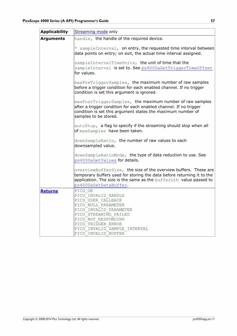
PicoScope 4000 Series (A API) Programmer's Guide 57
Copyright © 2008-2014 Pico Technology Ltd. All rights reserved. ps4000apg.en r1
Applicability Streaming mode only
Arguments handle, the handle of the required device.
* sampleInterval, on entry, the requested time interval between
data points on entry; on exit, the actual time interval assigned.
sampleIntervalTimeUnits, the unit of time that the
sampleInterval is set to. See ps4000aGetTriggerTimeOffsetfor values.
maxPreTriggerSamples, the maximum number of raw samples
before a trigger condition for each enabled channel. If no triggercondition is set this argument is ignored.
maxPostTriggerSamples, the maximum number of raw samples
after a trigger condition for each enabled channel. If no triggercondition is set this argument states the maximum number ofsamples to be stored.
autoStop, a flag to specify if the streaming should stop when all
of maxSamples have been taken.
downSampleRatio, the number of raw values to each
downsampled value.
downSampleRatioMode, the type of data reduction to use. See
ps4000aGetValues for details.
overviewBufferSize, the size of the overview buffers. These are
temporary buffers used for storing the data before returning it to theapplication. The size is the same as the bufferLth value passed to
ps4000aSetDataBuffer.
Returns PICO_OKPICO_INVALID_HANDLEPICO_USER_CALLBACKPICO_NULL_PARAMETERPICO_INVALID_PARAMETERPICO_STREAMING_FAILEDPICO_NOT_RESPONDINGPICO_TRIGGER_ERRORPICO_INVALID_SAMPLE_INTERVALPICO_INVALID_BUFFER
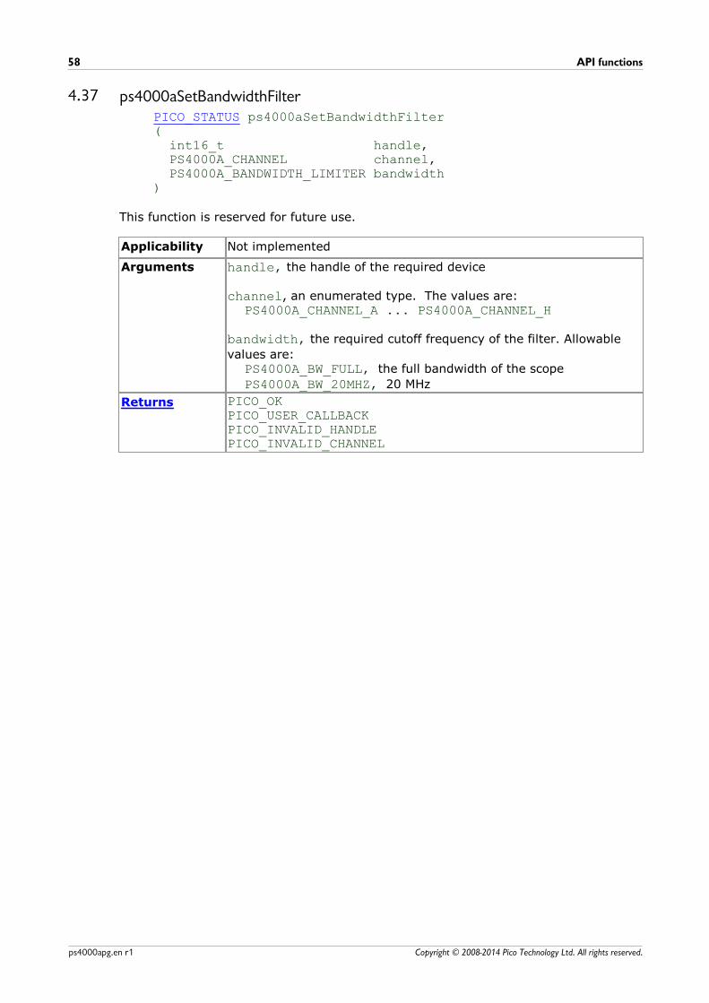
API functions58
Copyright © 2008-2014 Pico Technology Ltd. All rights reserved.ps4000apg.en r1
4.37 ps4000aSetBandwidthFilterPICO_STATUS ps4000aSetBandwidthFilter( int16_t handle, PS4000A_CHANNEL channel, PS4000A_BANDWIDTH_LIMITER bandwidth)
This function is reserved for future use.
Applicability Not implemented
Arguments handle, the handle of the required device
channel, an enumerated type. The values are:PS4000A_CHANNEL_A ... PS4000A_CHANNEL_H
bandwidth, the required cutoff frequency of the filter. Allowable
values are:PS4000A_BW_FULL, the full bandwidth of the scope
PS4000A_BW_20MHZ, 20 MHz
Returns PICO_OKPICO_USER_CALLBACKPICO_INVALID_HANDLEPICO_INVALID_CHANNEL
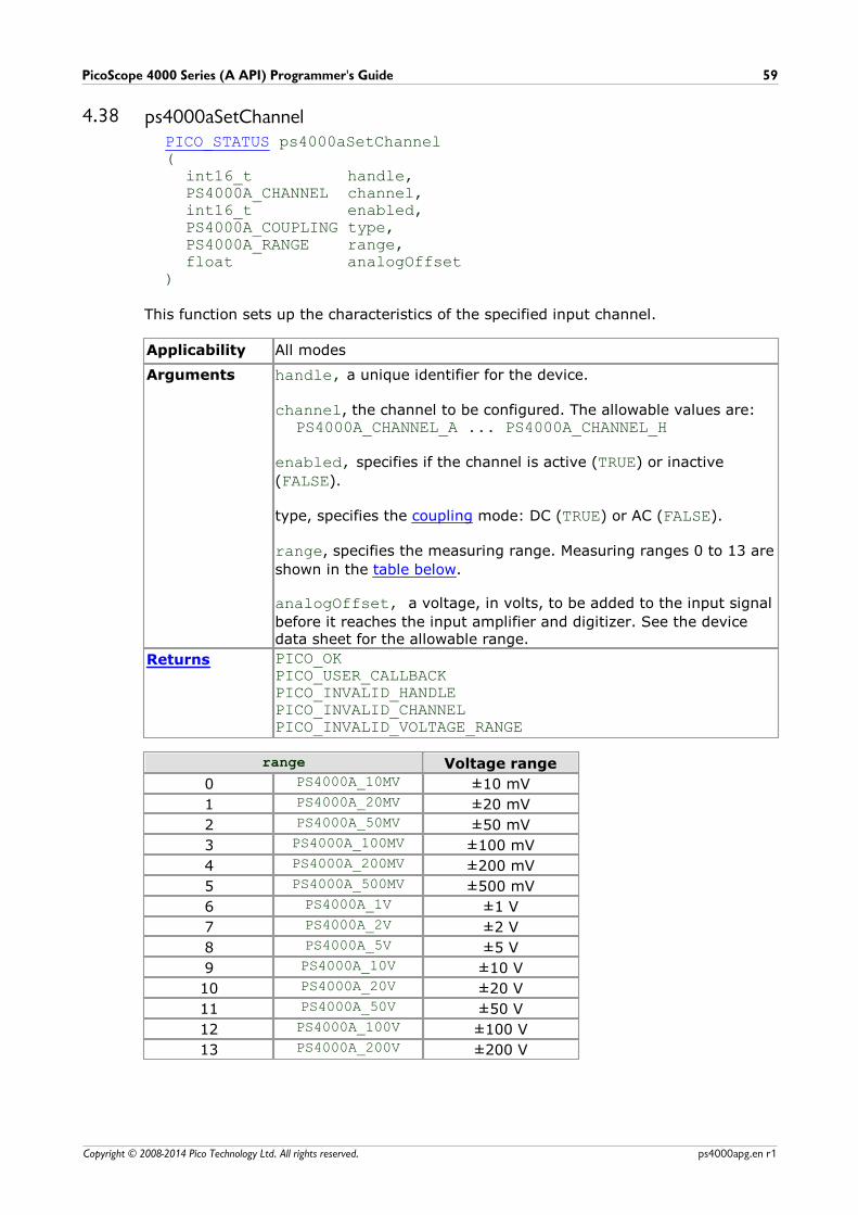
PicoScope 4000 Series (A API) Programmer's Guide 59
Copyright © 2008-2014 Pico Technology Ltd. All rights reserved. ps4000apg.en r1
4.38 ps4000aSetChannelPICO_STATUS ps4000aSetChannel (
int16_t handle,PS4000A_CHANNEL channel,int16_t enabled,PS4000A_COUPLING type,PS4000A_RANGE range,float analogOffset
)
This function sets up the characteristics of the specified input channel.
Applicability All modes
Arguments handle, a unique identifier for the device.
channel, the channel to be configured. The allowable values are:PS4000A_CHANNEL_A ... PS4000A_CHANNEL_H
enabled, specifies if the channel is active (TRUE) or inactive
(FALSE).
type, specifies the coupling mode: DC (TRUE) or AC (FALSE).
range, specifies the measuring range. Measuring ranges 0 to 13 are
shown in the table below.
analogOffset, a voltage, in volts, to be added to the input signal
before it reaches the input amplifier and digitizer. See the devicedata sheet for the allowable range.
Returns PICO_OKPICO_USER_CALLBACKPICO_INVALID_HANDLEPICO_INVALID_CHANNELPICO_INVALID_VOLTAGE_RANGE
range Voltage range
0 PS4000A_10MV ±10 mV
1 PS4000A_20MV ±20 mV
2 PS4000A_50MV ±50 mV
3 PS4000A_100MV ±100 mV
4 PS4000A_200MV ±200 mV
5 PS4000A_500MV ±500 mV
6 PS4000A_1V ±1 V
7 PS4000A_2V ±2 V
8 PS4000A_5V ±5 V
9 PS4000A_10V ±10 V
10 PS4000A_20V ±20 V
11 PS4000A_50V ±50 V
12 PS4000A_100V ±100 V
13 PS4000A_200V ±200 V

API functions60
Copyright © 2008-2014 Pico Technology Ltd. All rights reserved.ps4000apg.en r1
4.39 ps4000aSetDataBufferPICO_STATUS ps4000aSetDataBuffer(
int16_t handle,PS4000A_CHANNEL channel,int16_t * buffer,int32_t bufferLth,uint32_t segmentIndex,PS4000A_RATIO_MODE mode
)
This function registers your data buffer, for non-downsampled data, with thePicoScope 4000 driver. You need to allocate the buffer before calling this function.
Applicability All modes.
For downsampled data, use ps4000aSetDataBuffers instead.
Arguments handle, the handle of the required device
channel, the channel for which you want to set the buffers. Use
one of these values:PS4000A_CHANNEL_A ... PS4000A_CHANNEL_H
* buffer, a buffer to receive the data values
bufferLth, the size of the buffer array
segmentIndex, the serial number of the segment to be retrieved
mode, the type of data reduction to use. See Downsampling for
options.
Returns PICO_OKPICO_INVALID_HANDLEPICO_INVALID_CHANNEL
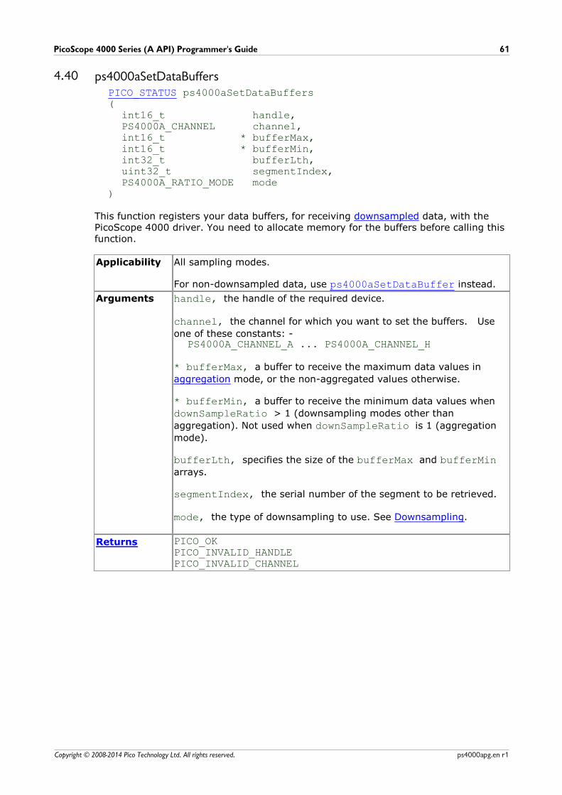
PicoScope 4000 Series (A API) Programmer's Guide 61
Copyright © 2008-2014 Pico Technology Ltd. All rights reserved. ps4000apg.en r1
4.40 ps4000aSetDataBuffersPICO_STATUS ps4000aSetDataBuffers(
int16_t handle,PS4000A_CHANNEL channel,int16_t * bufferMax,int16_t * bufferMin,int32_t bufferLth,uint32_t segmentIndex,PS4000A_RATIO_MODE mode
)
This function registers your data buffers, for receiving downsampled data, with thePicoScope 4000 driver. You need to allocate memory for the buffers before calling thisfunction.
Applicability All sampling modes.
For non-downsampled data, use ps4000aSetDataBuffer instead.
Arguments handle, the handle of the required device.
channel, the channel for which you want to set the buffers. Use
one of these constants: -PS4000A_CHANNEL_A ... PS4000A_CHANNEL_H
* bufferMax, a buffer to receive the maximum data values in
aggregation mode, or the non-aggregated values otherwise.
* bufferMin, a buffer to receive the minimum data values when
downSampleRatio > 1 (downsampling modes other than
aggregation). Not used when downSampleRatio is 1 (aggregation
mode).
bufferLth, specifies the size of the bufferMax and bufferMinarrays.
segmentIndex, the serial number of the segment to be retrieved.
mode, the type of downsampling to use. See Downsampling.
Returns PICO_OKPICO_INVALID_HANDLEPICO_INVALID_CHANNEL

API functions62
Copyright © 2008-2014 Pico Technology Ltd. All rights reserved.ps4000apg.en r1
4.41 ps4000aSetEtsPICO_STATUS ps4000aSetEts(
int16_t handle,PS4000A_ETS_MODE mode,int16_t etsCycles,int16_t etsInterleave,int32_t * sampleTimePicoseconds
)
This function is reserved for future use.
Applicability Not implemented
Arguments handle, the handle of the required device
mode, not used
ets_cycles, not used
ets_interleave, not used
* sampleTimePicoseconds, not used
Returns PICO_ETS_NOT_SUPPORTED

PicoScope 4000 Series (A API) Programmer's Guide 63
Copyright © 2008-2014 Pico Technology Ltd. All rights reserved. ps4000apg.en r1
4.42 ps4000aSetEtsTimeBufferPICO_STATUS ps4000aSetEtsTimeBuffer(
int16_t handle,int64_t * buffer,int32_t bufferLth
)
This is reserved for future use.
Applicability Not implemented
Arguments handle, the handle of the required device
* buffer, not used
bufferLth, not used
Returns PICO_ETS_NOT_SUPPORTED
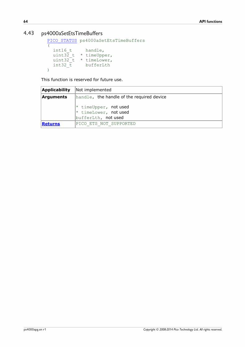
API functions64
Copyright © 2008-2014 Pico Technology Ltd. All rights reserved.ps4000apg.en r1
4.43 ps4000aSetEtsTimeBuffersPICO_STATUS ps4000aSetEtsTimeBuffers(
int16_t handle,uint32_t * timeUpper,uint32_t * timeLower,int32_t bufferLth
)
This function is reserved for future use.
Applicability Not implemented
Arguments handle, the handle of the required device
* timeUpper, not used
* timeLower, not used
bufferLth, not used
Returns PICO_ETS_NOT_SUPPORTED
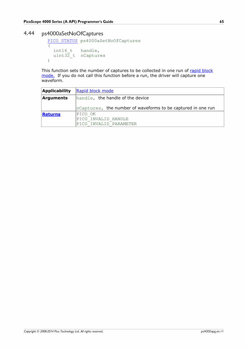
PicoScope 4000 Series (A API) Programmer's Guide 65
Copyright © 2008-2014 Pico Technology Ltd. All rights reserved. ps4000apg.en r1
4.44 ps4000aSetNoOfCapturesPICO_STATUS ps4000aSetNoOfCaptures (
int16_t handle,uint32_t nCaptures
)
This function sets the number of captures to be collected in one run of rapid blockmode. If you do not call this function before a run, the driver will capture onewaveform.
Applicability Rapid block mode
Arguments handle, the handle of the device
nCaptures, the number of waveforms to be captured in one run
Returns PICO_OKPICO_INVALID_HANDLEPICO_INVALID_PARAMETER

API functions66
Copyright © 2008-2014 Pico Technology Ltd. All rights reserved.ps4000apg.en r1
4.45 ps4000aSetPulseWidthQualifierConditionsPICO_STATUS ps4000aSetPulseWidthQualifierConditions(
int16_t handle,PS4000A_CONDITION * conditions,int16_t nConditions,PS4000A_CONDITIONS_INFO info
)
This function sets up the conditions for pulse width qualification, which can be used onits own for pulse width triggering or combined with window triggering to produce morecomplex triggers. Each call to this function creates a pulse width qualifier equal to thelogical AND of the elements of the conditions array. Calling this function multiple
times creates the logical OR of multiple AND operations. This AND-OR logic allows youto create any possible Boolean function of the scope's inputs.
Other settings of the pulse width qualifier are configured by calling ps4000SetPulseWidthQualifierProperties.
Applicability All modes
Arguments handle, the handle of the required device
* conditions, see ps4000aTriggerConditionsnConditions, see ps4000aTriggerConditionsinfo, see ps4000aTriggerConditions
Returns PICO_OKPICO_INVALID_HANDLEPICO_USER_CALLBACKPICO_CONDITIONSPICO_PULSE_WIDTH_QUALIFIER
PicoScope 4000 Series (A API) Programmer's Guide 67
Copyright © 2008-2014 Pico Technology Ltd. All rights reserved. ps4000apg.en r1
4.46 ps4000aSetPulseWidthQualifierPropertiesPICO_STATUS ps4000aSetPulseWidthQualifierProperties(
int16_t handle,PS4000A_THRESHOLD_DIRECTION direction,uint32_t lower,uint32_t upper,PS4000A_PULSE_WIDTH_TYPE type
)
This function configures the general properties of the pulse width qualifier.
Applicability All modes
Arguments handle, the handle of the required device
direction, the direction of the signal required for the trigger to
fire. See PS4000A_DIRECTION for allowable values.
lower, the lower limit of the pulse width counter
upper, the upper limit of the pulse width counter. This parameter is
used only when the type is set to PW_TYPE_IN_RANGE orPW_TYPE_OUT_OF_RANGE.
type, the pulse width type, one of these constants:
PW_TYPE_NONE (do not use the pulse width qualifier)
PW_TYPE_LESS_THAN (pulse width less than lower)
PW_TYPE_GREATER_THAN (pulse width greater than lower)
PW_TYPE_IN_RANGE (pulse width between lower and upper)
PW_TYPE_OUT_OF_RANGE (pulse width not between lower and
upper)
Returns PICO_OKPICO_INVALID_HANDLEPICO_USER_CALLBACKPICO_CONDITIONSPICO_PULSE_WIDTH_QUALIFIER
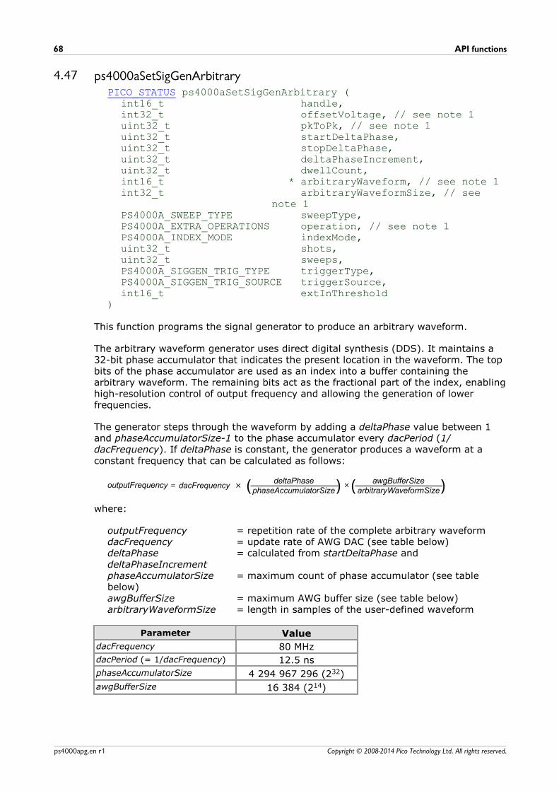
API functions68
Copyright © 2008-2014 Pico Technology Ltd. All rights reserved.ps4000apg.en r1
4.47 ps4000aSetSigGenArbitraryPICO_STATUS ps4000aSetSigGenArbitrary (
int16_t handle,int32_t offsetVoltage, // see note 1uint32_t pkToPk, // see note 1uint32_t startDeltaPhase,uint32_t stopDeltaPhase,uint32_t deltaPhaseIncrement,uint32_t dwellCount,int16_t * arbitraryWaveform, // see note 1int32_t arbitraryWaveformSize, // see
note 1PS4000A_SWEEP_TYPE sweepType,PS4000A_EXTRA_OPERATIONS operation, // see note 1PS4000A_INDEX_MODE indexMode,uint32_t shots,uint32_t sweeps,PS4000A_SIGGEN_TRIG_TYPE triggerType,PS4000A_SIGGEN_TRIG_SOURCE triggerSource,int16_t extInThreshold
)
This function programs the signal generator to produce an arbitrary waveform.
The arbitrary waveform generator uses direct digital synthesis (DDS). It maintains a32-bit phase accumulator that indicates the present location in the waveform. The topbits of the phase accumulator are used as an index into a buffer containing thearbitrary waveform. The remaining bits act as the fractional part of the index, enablinghigh-resolution control of output frequency and allowing the generation of lowerfrequencies.
The generator steps through the waveform by adding a deltaPhase value between 1and phaseAccumulatorSize-1 to the phase accumulator every dacPeriod (1/dacFrequency). If deltaPhase is constant, the generator produces a waveform at aconstant frequency that can be calculated as follows:
( ) ( )outputFrequency = dacFrequency ×deltaPhase
phaseAccumulatorSize×
awgBufferSizearbitraryWaveformSize
where:
outputFrequency = repetition rate of the complete arbitrary waveformdacFrequency = update rate of AWG DAC (see table below)deltaPhase = calculated from startDeltaPhase anddeltaPhaseIncrementphaseAccumulatorSize = maximum count of phase accumulator (see tablebelow)awgBufferSize = maximum AWG buffer size (see table below)arbitraryWaveformSize = length in samples of the user-defined waveform
Parameter Value
dacFrequency 80 MHz
dacPeriod (= 1/dacFrequency) 12.5 ns
phaseAccumulatorSize 4 294 967 296 (232)
awgBufferSize 16 384 (214)

PicoScope 4000 Series (A API) Programmer's Guide 69
Copyright © 2008-2014 Pico Technology Ltd. All rights reserved. ps4000apg.en r1
It is also possible to sweep the frequency by continually modifying the deltaPhase.This is done by setting up a deltaPhaseIncrement that the oscilloscope adds to thedeltaPhase at specified intervals.
Note 1: in general, this function can be called with new arguments while waiting for atrigger; the exceptions are the arguments offsetVoltage, pkToPk,arbitraryWaveform, arbitraryWaveformSize and operation, which must
unchanged on subsequent calls, otherwise the function will return a PICO_BUSYstatus code.
Applicability All modes
Arguments
handle, the handle of the required device.
offsetVoltage, the voltage offset, in microvolts, to be applied to the waveform.
pkToPk, the peak-to-peak voltage, in microvolts, of the waveform signal.
startDeltaPhase, the initial value added to the phase counter as the generator
begins to step through the waveform buffer.
stopDeltaPhase, the final value added to the phase counter before the generator
restarts or reverses the sweep. When frequency sweeping is not required, set equalto startDeltaPhase.
deltaPhaseIncrement, the amount added to the delta phase value every time
the dwellCount period expires. This determines the amount by which the
generator sweeps the output frequency in each dwell period. When frequencysweeping is not required, set to zero.
dwellCount, the time, in multiples of dacPeriod, between successive additions of
deltaPhaseIncrement to the delta phase counter. This determines the rate at
which the generator sweeps the output frequency. Minimum allowable values are asfollows:
PicoScope 4824: MIN_DWELL_COUNT
* arbitraryWaveform, a buffer that holds the waveform pattern as a set of
samples equally spaced in time. The sample value range is [0, 4095].
arbitraryWaveformSize, the size of the arbitrary waveform buffer, in samples:
Min: MIN_SIG_GEN_BUFFER_SIZE (1)
Max: MAX_SIG_GEN_BUFFER_SIZE (16 384)
sweepType, determines whether the startDeltaPhase is swept up to the
stopDeltaPhase, or down to it, or repeatedly up and down. Use one of the
following values: UP, DOWN, UPDOWN, DOWNUP.
operation, configures the white noise/PRBS (pseudo-random binary sequence)
generator:PS4000A_ES_OFF: White noise/PRBS output disabled. The waveform is
defined by the other arguments.PS4000A_WHITENOISE: The signal generator produces white noise and
ignores all settings except offsetVoltage andpkTopk.
PS4000A_PRBS: The signal generator produces a PRBS.
API functions70
Copyright © 2008-2014 Pico Technology Ltd. All rights reserved.ps4000apg.en r1
indexMode, specifies how the signal will be formed from the arbitrary waveform
data. SINGLE, DUAL and QUAD index modes are possible (see AWG index modes).
shots, the number of cycles of the waveform to be produced after a trigger event.
If this is set to a non-zero value [1, MAX_SWEEPS_SHOTS], then sweeps must be set
to zero.
sweeps, the number of times to sweep the frequency after a trigger event,
according to sweepType. If this is set to a non-zero value [1,
MAX_SWEEPS_SHOTS], then shots must be set to zero.
triggerType, the type of trigger that will be applied to the signal generator:SIGGEN_RISING: rising edgeSIGGEN_FALLING: falling edgeSIGGEN_GATE_HIGH: high level SIGGEN_GATE_LOW: low level
triggerSource, the source that will trigger the signal generator:SIGGEN_NONE: no trigger (free-running)SIGGEN_SCOPE_TRIG: the selected oscilloscope channel (see
ps4000aSetSimpleTrigger)SIGGEN_SOFT_TRIG: a software trigger (see
ps4000aSigGenSoftwareControl)
If a trigger source other than SIGGEN_NONE is specified, then either shots or
sweeps, but not both, must be set to a non-zero value.
extInThreshold, not used
Returns 0: if successful.Error code: if failed
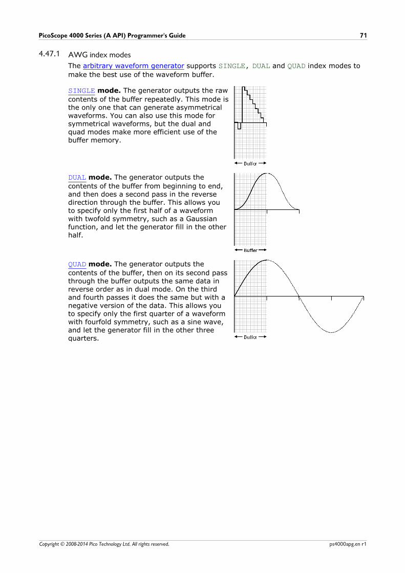
PicoScope 4000 Series (A API) Programmer's Guide 71
Copyright © 2008-2014 Pico Technology Ltd. All rights reserved. ps4000apg.en r1
4.47.1 AWG index modes
The arbitrary waveform generator supports SINGLE, DUAL and QUAD index modes to
make the best use of the waveform buffer.
SINGLE mode. The generator outputs the raw
contents of the buffer repeatedly. This mode isthe only one that can generate asymmetricalwaveforms. You can also use this mode forsymmetrical waveforms, but the dual andquad modes make more efficient use of thebuffer memory.
DUAL mode. The generator outputs the
contents of the buffer from beginning to end,and then does a second pass in the reversedirection through the buffer. This allows youto specify only the first half of a waveformwith twofold symmetry, such as a Gaussianfunction, and let the generator fill in the otherhalf.
QUAD mode. The generator outputs the
contents of the buffer, then on its second passthrough the buffer outputs the same data inreverse order as in dual mode. On the thirdand fourth passes it does the same but with anegative version of the data. This allows youto specify only the first quarter of a waveformwith fourfold symmetry, such as a sine wave,and let the generator fill in the other threequarters.

API functions72
Copyright © 2008-2014 Pico Technology Ltd. All rights reserved.ps4000apg.en r1
4.48 ps4000aSetSigGenBuiltInPICO_STATUS ps4000aSetSigGenBuiltIn (
int16_t handle,int32_t offsetVoltage, // see note 1uint32_t pkToPk, // see note 1PS4000A_WAVE_TYPE waveType, // see note 1double startFrequency,double stopFrequency,double increment,double dwellTime,PS4000A_SWEEP_TYPE sweepType,PS4000A_EXTRA_OPERATIONS operation, // see note 1uint32_t shots,uint32_t sweeps,PS4000A_SIGGEN_TRIG_TYPE triggerType,PS4000A_SIGGEN_TRIG_SOURCE triggerSource,int16_t extInThreshold
)
This function sets up the signal generator to produce a signal from a list of built-inwaveforms. If different start and stop frequencies are specified, the oscilloscope willsweep either up, down or up and down.
Note 1: in general, this function can be called with new arguments while waiting for atrigger; the exceptions are the arguments offsetVoltage, pkToPk,arbitraryWaveform, arbitraryWaveformSize and operation, which must
unchanged on subsequent calls, otherwise the function will return a PICO_BUSYstatus code.
Applicability All modes
Arguments handle, the handle of the required oscilloscope.
offsetVoltage, the voltage offset, in microvolts, to be applied to
the waveform.
pkToPk, the peak-to-peak voltage, in microvolts, of the waveform
signal.
waveType, the type of waveform to be generated by the
oscilloscope:
PS4000A_SINE sine wavePS4000A_SQUARE square wavePS4000A_TRIANGLE triangle wavePS4000A_RAMP_UP rising sawtoothPS4000A_RAMP_DOWN falling sawtoothPS4000A_SINC sin(x)/xPS4000A_GAUSSIAN normal distributionPS4000A_HALF_SINE full-wave rectified sinusoidPS4000A_DC_VOLTAGE DC voltagePS4000A_WHITE_NOISE random values
startFrequency, the frequency in hertz at which the signal
generator should begin. Range: MIN_SIG_GEN_FREQ toMAX_SIG_GEN_FREQ.
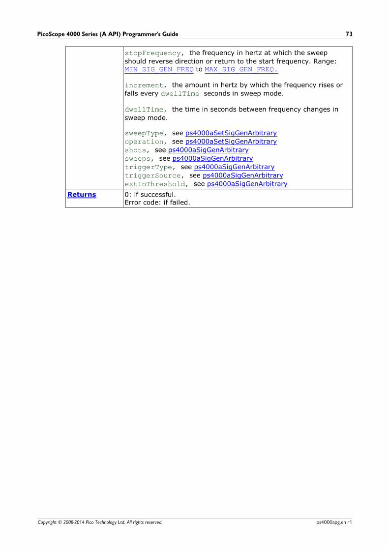
PicoScope 4000 Series (A API) Programmer's Guide 73
Copyright © 2008-2014 Pico Technology Ltd. All rights reserved. ps4000apg.en r1
stopFrequency, the frequency in hertz at which the sweep
should reverse direction or return to the start frequency. Range: MIN_SIG_GEN_FREQ to MAX_SIG_GEN_FREQ.
increment, the amount in hertz by which the frequency rises or
falls every dwellTime seconds in sweep mode.
dwellTime, the time in seconds between frequency changes in
sweep mode.
sweepType, see ps4000aSetSigGenArbitrary
operation, see ps4000aSetSigGenArbitrary
shots, see ps4000aSigGenArbitrary
sweeps, see ps4000aSigGenArbitrary
triggerType, see ps4000aSigGenArbitrary
triggerSource, see ps4000aSigGenArbitrary
extInThreshold, see ps4000aSigGenArbitrary
Returns 0: if successful.Error code: if failed.
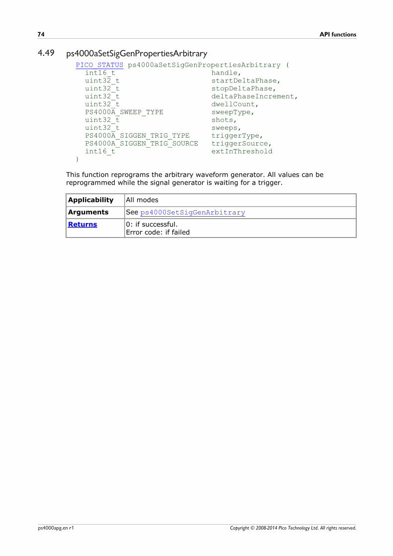
API functions74
Copyright © 2008-2014 Pico Technology Ltd. All rights reserved.ps4000apg.en r1
4.49 ps4000aSetSigGenPropertiesArbitraryPICO_STATUS ps4000aSetSigGenPropertiesArbitrary (
int16_t handle,uint32_t startDeltaPhase,uint32_t stopDeltaPhase,uint32_t deltaPhaseIncrement,uint32_t dwellCount,PS4000A_SWEEP_TYPE sweepType,uint32_t shots,uint32_t sweeps,PS4000A_SIGGEN_TRIG_TYPE triggerType,PS4000A_SIGGEN_TRIG_SOURCE triggerSource,int16_t extInThreshold
)
This function reprograms the arbitrary waveform generator. All values can bereprogrammed while the signal generator is waiting for a trigger.
Applicability All modes
Arguments See ps4000SetSigGenArbitrary
Returns 0: if successful.Error code: if failed
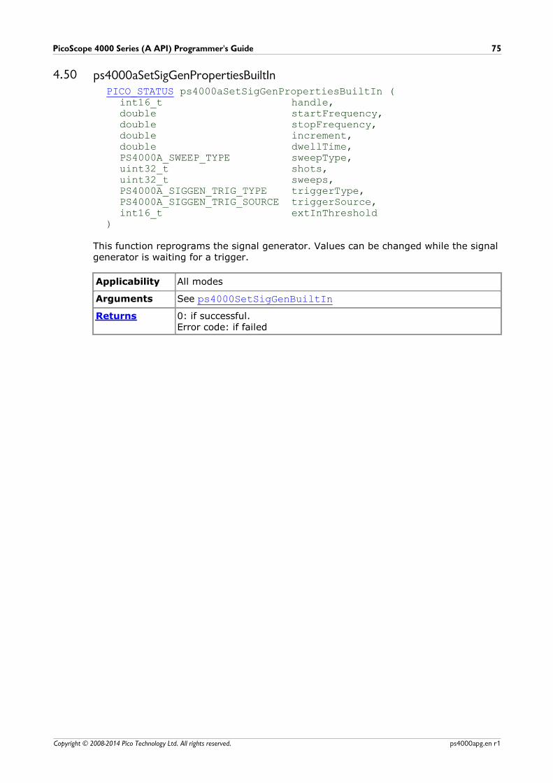
PicoScope 4000 Series (A API) Programmer's Guide 75
Copyright © 2008-2014 Pico Technology Ltd. All rights reserved. ps4000apg.en r1
4.50 ps4000aSetSigGenPropertiesBuiltInPICO_STATUS ps4000aSetSigGenPropertiesBuiltIn (
int16_t handle,double startFrequency,double stopFrequency,double increment,double dwellTime,PS4000A_SWEEP_TYPE sweepType,uint32_t shots,uint32_t sweeps,PS4000A_SIGGEN_TRIG_TYPE triggerType,PS4000A_SIGGEN_TRIG_SOURCE triggerSource,int16_t extInThreshold
)
This function reprograms the signal generator. Values can be changed while the signalgenerator is waiting for a trigger.
Applicability All modes
Arguments See ps4000SetSigGenBuiltIn
Returns 0: if successful.Error code: if failed

API functions76
Copyright © 2008-2014 Pico Technology Ltd. All rights reserved.ps4000apg.en r1
4.51 ps4000aSetSimpleTriggerPICO_STATUS ps4000aSetSimpleTrigger( int16_t handle, int16_t enable, PS4000A_CHANNEL source, int16_t threshold, PS4000A_THRESHOLD_DIRECTION direction, uint32_t delay, int16_t autoTrigger_ms)
This function simplifies arming the trigger. It supports only the LEVEL trigger types
and does not allow more than one channel to have a trigger applied to it. Anyprevious pulse width qualifier is cancelled.
Applicability All modes
Arguments handle, the handle of the required device.
enabled, zero to disable the trigger, any non-zero value to set the
trigger.
source, the channel on which to trigger. See ps4000aSetChannel.
threshold, the ADC count at which the trigger will fire.
direction, the direction in which the signal must move to cause a
trigger. The following directions are supported: ABOVE, BELOW,
RISING, FALLING and RISING_OR_FALLING.
delay, the time, in sample periods, between the trigger occurring
and the first sample being taken.
autoTrigger_ms, the number of milliseconds the device will wait if
no trigger occurs.
Returns PICO_OKPICO_INVALID_HANDLEPICO_USER_CALLBACKPICO_DRIVER_FUNCTION

PicoScope 4000 Series (A API) Programmer's Guide 77
Copyright © 2008-2014 Pico Technology Ltd. All rights reserved. ps4000apg.en r1
4.52 ps4000aSetTriggerChannelConditionsPICO_STATUS ps4000aSetTriggerChannelConditions(
int16_t handle,PS4000A_CONDITION * conditions,int16_t nConditions,PS4000A_CONDITIONS_INFO info
)
This function sets up trigger conditions on the scope's inputs. The trigger is set up bydefining an array of one or more PS4000A_CONDITION structures that are then
ANDed together. The function can be called multiple times, in which case the triggerlogic is ORed with that defined by previous calls. This AND-OR logic allows you tocreate any possible Boolean function of the scope's inputs.
Applicability All modes
Arguments handle, the handle of the required device.
* conditions, an array of PS4000A_CONDITION structures
specifying the conditions that should be applied to each channel. Inthe simplest case, the array consists of a single element. When thereare several elements, the overall trigger condition is the logical ANDof all the elements.
nConditions, the number of elements in the conditions array,
or zero to switch off triggering.
info, determines whether the function clears previous conditions:
PS4000A_CLEAR, clears previous conditions
PS4000A_ADD, adds the specified conditions (ORing them with
previously set conditions, if any)
You can combine both actions by passing (PS4000A_CONDITIONS_INFO)(PS4000A_CLEAR |PS4000A_ADD).
Returns PICO_OKPICO_INVALID_HANDLEPICO_USER_CALLBACKPICO_CONDITIONSPICO_MEMORY_FAIL
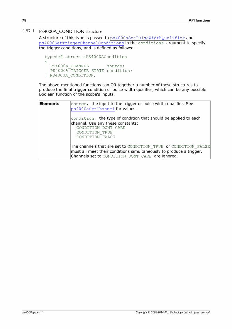
API functions78
Copyright © 2008-2014 Pico Technology Ltd. All rights reserved.ps4000apg.en r1
4.52.1 PS4000A_CONDITION structure
A structure of this type is passed to ps4000aSetPulseWidthQualifier and
ps4000SetTriggerChannelConditions in the conditions argument to specify
the trigger conditions, and is defined as follows: -
typedef struct tPS4000ACondition{
PS4000A_CHANNEL source;PS4000A_TRIGGER_STATE condition;
} PS4000A_CONDITION;
The above-mentioned functions can OR together a number of these structures toproduce the final trigger condition or pulse width qualifier, which can be any possibleBoolean function of the scope's inputs.
Elements source, the input to the trigger or pulse width qualifier. See
ps4000aSetChannel for values.
condition, the type of condition that should be applied to each
channel. Use any these constants:CONDITION_DONT_CARECONDITION_TRUECONDITION_FALSE
The channels that are set to CONDITION_TRUE or CONDITION_FALSEmust all meet their conditions simultaneously to produce a trigger.Channels set to CONDITION_DONT_CARE are ignored.
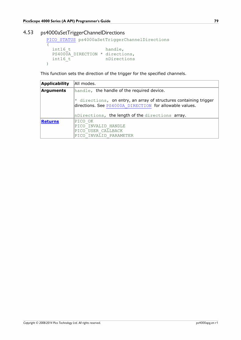
PicoScope 4000 Series (A API) Programmer's Guide 79
Copyright © 2008-2014 Pico Technology Ltd. All rights reserved. ps4000apg.en r1
4.53 ps4000aSetTriggerChannelDirectionsPICO_STATUS ps4000aSetTriggerChannelDirections(
int16_t handle,PS4000A_DIRECTION * directions,int16_t nDirections
)
This function sets the direction of the trigger for the specified channels.
Applicability All modes.
Arguments handle, the handle of the required device.
* directions, on entry, an array of structures containing trigger
directions. See PS4000A_DIRECTION for allowable values.
nDirections, the length of the directions array.
Returns PICO_OKPICO_INVALID_HANDLEPICO_USER_CALLBACKPICO_INVALID_PARAMETER
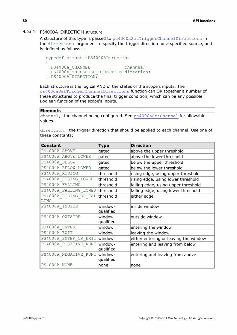
API functions80
Copyright © 2008-2014 Pico Technology Ltd. All rights reserved.ps4000apg.en r1
4.53.1 PS4000A_DIRECTION structure
A structure of this type is passed to ps4000aSetTriggerChannelDirections in
the directions argument to specify the trigger direction for a specified source, and
is defined as follows: -
typedef struct tPS4000ADirection{ PS4000A_CHANNEL channel; PS4000A_THRESHOLD_DIRECTION direction;} PS4000A_DIRECTION;
Each structure is the logical AND of the states of the scope's inputs. The ps4000aSetTriggerChannelDirections function can OR together a number of
these structures to produce the final trigger condition, which can be any possibleBoolean function of the scope's inputs.
Elements
channel, the channel being configured. See ps4000aSetChannel for allowable
values.
direction, the trigger direction that should be applied to each channel. Use one of
these constants:
Constant Type Direction
PS4000A_ABOVE gated above the upper threshold
PS4000A_ABOVE_LOWER gated above the lower threshold
PS4000A_BELOW gated below the upper threshold
PS4000A_BELOW_LOWER gated below the lower threshold
PS4000A_RISING threshold rising edge, using upper threshold
PS4000A_RISING_LOWER threshold rising edge, using lower threshold
PS4000A_FALLING threshold falling edge, using upper threshold
PS4000A_FALLING_LOWER threshold falling edge, using lower threshold
PS4000A_RISING_OR_FALLING
threshold either edge
PS4000A_INSIDE window-qualified
inside window
PS4000A_OUTSIDE window-qualified
outside window
PS4000A_ENTER window entering the window
PS4000A_EXIT window leaving the window
PS4000A_ENTER_OR_EXIT window either entering or leaving the window
PS4000A_POSITIVE_RUNT window-qualified
entering and leaving from below
PS4000A_NEGATIVE_RUNT window-qualified
entering and leaving from above
PS4000A_NONE none none
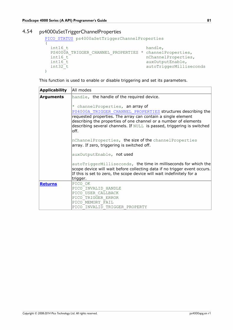
PicoScope 4000 Series (A API) Programmer's Guide 81
Copyright © 2008-2014 Pico Technology Ltd. All rights reserved. ps4000apg.en r1
4.54 ps4000aSetTriggerChannelPropertiesPICO_STATUS ps4000aSetTriggerChannelProperties(
int16_t handle,PS4000A_TRIGGER_CHANNEL_PROPERTIES * channelProperties,int16_t nChannelProperties,int16_t auxOutputEnable,int32_t autoTriggerMilliseconds
)
This function is used to enable or disable triggering and set its parameters.
Applicability All modes
Arguments handle, the handle of the required device.
* channelProperties, an array of
PS4000A_TRIGGER_CHANNEL_PROPERTIES structures describing the
requested properties. The array can contain a single elementdescribing the properties of one channel or a number of elementsdescribing several channels. If NULL is passed, triggering is switched
off.
nChannelProperties, the size of the channelPropertiesarray. If zero, triggering is switched off.
auxOutputEnable, not used
autoTriggerMilliseconds, the time in milliseconds for which the
scope device will wait before collecting data if no trigger event occurs.If this is set to zero, the scope device will wait indefinitely for atrigger.
Returns PICO_OKPICO_INVALID_HANDLEPICO_USER_CALLBACKPICO_TRIGGER_ERRORPICO_MEMORY_FAILPICO_INVALID_TRIGGER_PROPERTY

API functions82
Copyright © 2008-2014 Pico Technology Ltd. All rights reserved.ps4000apg.en r1
4.54.1 PS4000A_TRIGGER_CHANNEL_PROPERTIES structure
A structure of this type is passed to ps4000aSetTriggerChannelProperties in
the channelProperties argument to specify the trigger mechanism, and is defined
as follows:
typedef struct tPS4000ATriggerChannelProperties{
int16_t thresholdUpper;uint16_t thresholdUpperHysteresis;int16_t thresholdLower;uint16_t thresholdLowerHysteresis;PS4000A_CHANNEL channel;PS4000A_THRESHOLD_MODE thresholdMode;
} PS4000A_TRIGGER_CHANNEL_PROPERTIES
Elements thresholdUpper, the upper threshold at which the trigger must
fire. This is scaled in 16-bit ADC counts at the currently selected rangefor that channel.
thresholdUpperHysteresis, the hysteresis by which the trigger
must exceed the upper threshold before it will fire. It is scaled in 16-bit counts.
thresholdLower, the lower threshold at which the trigger must
fire. This is scaled in 16-bit ADC counts at the currently selected rangefor that channel.
thresholdLowerHysteresis, the hysteresis by which the trigger
must exceed the lower threshold before it will fire. It is scaled in 16-bit counts.
channel, the channel to which the properties apply. See
ps4000aSetChannel for possible values.
thresholdMode, either a level or window trigger. Use one of these
constants:PS4000A_LEVELPS4000A_WINDOW
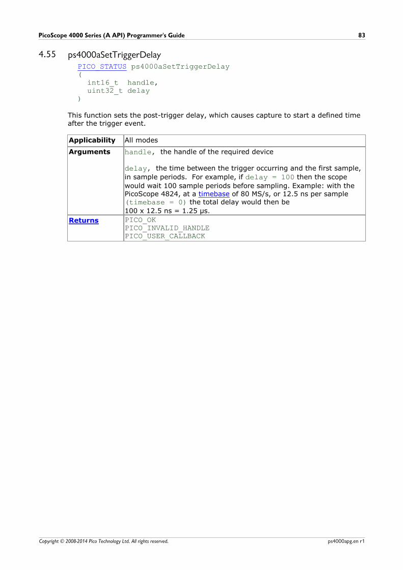
PicoScope 4000 Series (A API) Programmer's Guide 83
Copyright © 2008-2014 Pico Technology Ltd. All rights reserved. ps4000apg.en r1
4.55 ps4000aSetTriggerDelayPICO_STATUS ps4000aSetTriggerDelay(
int16_t handle,uint32_t delay
)
This function sets the post-trigger delay, which causes capture to start a defined timeafter the trigger event.
Applicability All modes
Arguments handle, the handle of the required device
delay, the time between the trigger occurring and the first sample,
in sample periods. For example, if delay = 100 then the scope
would wait 100 sample periods before sampling. Example: with thePicoScope 4824, at a timebase of 80 MS/s, or 12.5 ns per sample(timebase = 0) the total delay would then be
100 x 12.5 ns = 1.25 µs.
Returns PICO_OKPICO_INVALID_HANDLEPICO_USER_CALLBACK
API functions84
Copyright © 2008-2014 Pico Technology Ltd. All rights reserved.ps4000apg.en r1
4.56 ps4000aSigGenSoftwareControlPICO_STATUS ps4000aSigGenSoftwareControl(
int16_t handle,int16_t state
)
This function causes a trigger event, or starts and stops gating. It is used when thesignal generator is set to SIGGEN_SOFT_TRIG .
Applicability Use with ps4000aSetSigGenBuiltIn or
ps4000aSetSigGenArbitrary.
Arguments handle, the handle of the required device
state, sets the trigger gate high or low when the trigger type is
set to either SIGGEN_GATE_HIGH or SIGGEN_GATE_LOW. Ignored
for other trigger types.
Returns PICO_OKPICO_INVALID_HANDLEPICO_NO_SIGNAL_GENERATOR PICO_SIGGEN_TRIGGER_SOURCE
PicoScope 4000 Series (A API) Programmer's Guide 85
Copyright © 2008-2014 Pico Technology Ltd. All rights reserved. ps4000apg.en r1
4.57 ps4000aStopPICO_STATUS ps4000aStop(
int16_t handle)
This function stops the scope device from sampling data. If this function is calledbefore a trigger event occurs, the oscilloscope may not contain valid data.
Always call this function after the end of a capture to ensure that the scope is readyfor the next capture.
Applicability All modes
Arguments handle, the handle of the required device.
Returns PICO_OKPICO_INVALID_HANDLEPICO_USER_CALLBACK

API functions86
Copyright © 2008-2014 Pico Technology Ltd. All rights reserved.ps4000apg.en r1
4.58 ps4000aStreamingReadytypedef void (CALLBACK *ps4000aStreamingReady)(
int16_t handle,int32_t noOfSamples,uint32_t startIndex,int16_t overflow,uint32_t triggerAt,int16_t triggered,int16_t autoStop,void * pParameter
)
This callback function is part of your application. You register it with the PicoScope4000 Series driver using ps4000aGetStreamingLatestValues, and the driver calls
it back when streaming-mode data is ready. You can then download the data usingthe ps4000aGetValuesAsync function.
Applicability Streaming mode only
Arguments handle, the handle of the device returning the samples.
noOfSamples, the number of samples to collect.
startIndex, an index to the first valid sample in the buffer. This
is the buffer that was previously passed to ps4000aSetDataBuffer.
overflow, returns a set of flags that indicate whether an
overvoltage has occurred on any of the channels. It is a bit patternwith bit 0 denoting Channel A.
triggerAt, an index to the buffer indicating the location of the
trigger point. This parameter is valid only when triggered is non-
zero.
triggered, a flag indicating whether a trigger occurred. If non-
zero, a trigger occurred at the location indicated by triggerAt.
autoStop, the flag that was set in the call to
ps4000aRunStreaming.
pParameter, a void pointer passed from
ps4000aGetStreamingLatestValues. The callback function can
write to this location to send any data, such as a status flag, back tothe application.
Returns nothing

PicoScope 4000 Series (A API) Programmer's Guide 87
Copyright © 2008-2014 Pico Technology Ltd. All rights reserved. ps4000apg.en r1
5 Enumerated types and constantsEnumerated types and constants are defined in the file ps4000aApi.h, which is
included in the SDK. We recommend that you refer to these constants by name unlessyour programming environment understands only numeric values.

Driver status codes88
Copyright © 2008-2014 Pico Technology Ltd. All rights reserved.ps4000apg.en r1
6 Driver status codesEvery function in the ps4000a.dll driver returns a status code from the list of
PICO_STATUS values defined in the picoStatus.h header file supplied with the SDK.
See the header file for more information.
PicoScope 4000 Series (A API) Programmer's Guide 89
Copyright © 2008-2014 Pico Technology Ltd. All rights reserved. ps4000apg.en r1
7 Programming examplesThe SDK includes programming examples for a number of languages and developmentenvironments.
7.1 CThe SDK includes a console-mode program (ps4000acon.c) that demonstrates how
to use the PicoScope 4000 driver in Windows. The program demonstrates the followingprocedures:
Open a PicoScope 4000 Series oscilloscopeCollect a block of samples immediatelyCollect a block of samples when a trigger event occursCollect a stream of data immediatelyCollect a stream of data when a trigger event occurs
To build this application:
Set up a project for a 32-bit or 64-bit console mode applicationAdd ps4000acon.c to the project
Add ps4000a.lib to the project (Microsoft C only)
Add ps4000aApi.h and picoStatus.h to the project
Build the project
7.2 ExcelThe Excel example demonstrates how to capture data in Excel from a PicoScope 4000Series scope.
1. Copy the following files (for a 32-bit Windows system) from the SDK to a locationthat is on your Windows execution path (for example, C:\windows\system32):
ps4000aWrap.dll ps4000a.dll PicoIpp.dll
2. Load the spreadsheet ps4000a.xls3. Select Tools | Macro4. Select GetData5. Select Run
Note: The Excel macro language is similar to Visual Basic. The functions which returna TRUE/FALSE value, return 0 for FALSE and 1 for TRUE, whereas Visual Basic
expects 65 535 for TRUE. Check for > 0 rather than = TRUE.
7.3 LabVIEWThe SDK contains a library of VIs that can be used to control the PicoScope 4000 andsome simple examples of using these VIs in streaming mode, block mode and rapidblock mode.
The LabVIEW library (PicoScope4000a.llb) can be placed in the user.libsubdirectory to make the VIs available on the ‘User Libraries’ palette. You must alsocopy ps4000a.dll and ps4000aWrap.dll to the folder containing your LabVIEW
project.
The library contains the following VIs:
Programming examples90
Copyright © 2008-2014 Pico Technology Ltd. All rights reserved.ps4000apg.en r1
PicoErrorHandler.vi - takes an error cluster and, if an error has occurred,
displays a message box indicating the source of the error and the status codereturned by the driver
PicoScope4000aAdvancedTriggerSettings.vi - an interface for the
advanced trigger features of the oscilloscope
This VI is not required for setting up simple triggers, which are configured using PicoScope4000aSettings.vi.
For further information on these trigger settings, see descriptions of the triggerfunctions:
ps4000aSetTriggerChannelConditionsps4000aSetTriggerChannelDirectionsps4000aSetTriggerChannelPropertiesps4000aSetPulseWidthQualifierConditionsps4000aSetPulseWidthQualifierPropertiesps4000aSetTriggerDelay
PicoScope4000aAWG.vi - controls the arbitrary waveform generator
Standard waveforms or an arbitrary waveform can be selected under ‘Wave Type’.There are three settings clusters: general settings that apply to both arbitrary andstandard waveforms, settings that apply only to standard waveforms and settingsthat apply only to arbitrary waveforms. It is not necessary to connect all of theseclusters if only using arbitrary waveforms or only using standard waveforms.
When selecting an arbitrary waveform, it is necessary to specify a text filecontaining the waveform. This text file should have a single value on each line inthe range –1 to 1. For further information on the settings, see descriptions of ps4000aSetSigGenBuiltIn and ps4000aSetSigGenArbitrary.
PicoScope4000aClose.vi - closes the oscilloscope
Should be called before exiting an application.
PicoScope4000aGetBlock.vi - collects a block of data from the oscilloscope
This can be called in a loop in order to continually collect blocks of data. Theoscilloscope should first be set up by using PicoScope4000aSettings.vi. The VI
outputs data arrays in two clusters (max and min). If not using aggregation, ‘MinBuffers’ is not used.
PicoScope4000aGetRapidBlock.vi - collects a set of data blocks or captures
from the oscilloscope in rapid block mode
This VI is similar to PicoScope4000aGetBlock.vi. It outputs two-dimensional
arrays for each channel that contain data from all the requested number ofcaptures.
PicoScope 4000 Series (A API) Programmer's Guide 91
Copyright © 2008-2014 Pico Technology Ltd. All rights reserved. ps4000apg.en r1
PicoScope4000aGetStreamingValues.vi - used in streaming mode to get the
latest values from the driver
This VI should be called in a loop after the oscilloscope has been set up using PicoScope4000aSettings.vi and streaming has been started by calling
PicoScope4000aStartStreaming.vi. The VI outputs the number of samples
available and the start index of these samples in the array output by PicoScope4000aStartStreaming.vi.
PicoScope4000aOpen.vi - opens a PicoScope 4000 and returns a handle to the
device
PicoScope4000aSettings.vi - sets up the oscilloscope
The inputs are clusters for setting up channels and simple triggers. Advancedtriggers can be set up using PicoScope4000aAdvancedTriggerSettings.vi.
PicoScope4000aStartStreaming.vi - starts the oscilloscope streaming
It outputs arrays that will contain samples once PicoScope4000aGetStreamingValues.vi has returned.
PicoStatus.vi - checks the status value returned by calls to the driver
If the driver returns an error, the status member of the error cluster is set to ‘true’and the error code and source are set.

Glossary92
Copyright © 2008-2014 Pico Technology Ltd. All rights reserved.ps4000apg.en r1
8 GlossaryAC/DC switch. To switch from AC coupling to DC coupling, or vice versa, select AC orDC from the control on the PicoScope toolbar. The AC setting filters out very low-frequency components of the input signal, including DC, and is suitable for viewingsmall AC signals superimposed on a DC or slowly changing offset. In this mode youcan measure the peak-to-peak amplitude of an AC signal but not its absolute value.Use the DC setting for measuring the absolute value of a signal.
ADC. Analog-to-digital converter. The electronic component in a PC oscilloscope thatconverts analog signals from the inputs into digital data suitable for transmission tothe PC.
Block mode. A sampling mode in which the computer prompts the oscilloscope tocollect a block of data into its internal memory before stopping the oscilloscope andtransferring the whole block into computer memory. Choose this mode of operationwhen the input signal being sampled contains high frequencies. Note: To avoidsampling errors, the maximum input frequency must be less than half the samplingrate.
Buffer size. The size of the oscilloscope buffer memory, measured in samples. Thebuffer allows the oscilloscope to sample data faster than it can transfer it to thecomputer.
Callback. A mechanism that the PicoScope 4000 driver uses to communicateasynchronously with your application. At design time, you add a function (a callbackfunction) to your application to deal with captured data. At run time, when you requestcaptured data from the driver, you also pass it a pointer to your function. The driverthen returns control to your application, allowing it to perform other tasks until thedata is ready. When this happens, the driver calls your function in a new thread tosignal that the data is ready. It is then up to your function to communicate this fact tothe rest of your application.
Device Manager. Device Manager is a Windows program that displays the currenthardware configuration of your computer. On Windows XP or Vista, right-click 'MyComputer,' choose 'Properties', then click the 'Hardware' tab and the 'Device Manager'button.
Driver. A program that controls a piece of hardware. The driver for the PicoScope4000 Series PC Oscilloscopes is supplied in the form of a 32-bit Windows DLL, ps4000.dll. This is used by the PicoScope software, and by user-designed
applications, to control the oscilloscopes.
ETS. Equivalent-time sampling. A technique for increasing the effective sampling rateof an oscilloscope beyond the maximum sampling rate of its ADC. The scope triggerson successive cycles of a repetitive waveform and collects one sample from each cycle.Each sample is delayed relative to the trigger by a time that increases with each cycle,so that after a number of cycles a complete period of the waveform has been sampled.The waveform must be stable and repetitive for this method to work.
GS/s. Gigasample (billion samples) per second.
Maximum sampling rate. A figure indicating the maximum number of samples theoscilloscope can acquire per second. The higher the sampling rate of the oscilloscope,the more accurate the representation of the high-frequency details in a fast signal.
MS/s. Megasample (million samples) per second.
PicoScope 4000 Series (A API) Programmer's Guide 93
Copyright © 2008-2014 Pico Technology Ltd. All rights reserved. ps4000apg.en r1
PC Oscilloscope. A virtual instrument formed by connecting a PicoScope 4000 Seriesscope unit to a computer running the PicoScope software.
PicoScope 4000 Series. A range of high-resolution PC Oscilloscopes from PicoTechnology. The range includes two-channel and four-channel models, with or withouta built-in function generator and arbitrary waveform generator.
PicoScope software. A software product that accompanies all Pico PC Oscilloscopes.It turns your PC into an oscilloscope, spectrum analyser, and meter display.
Streaming mode. A sampling mode in which the oscilloscope samples data andreturns it to the computer in an unbroken stream. This mode allows the capture ofdata sets whose size is not limited by the size of the scope's memory buffer, atsampling rates up to 160 million samples per second.
Timebase. The timebase controls the time interval that each horizontal division of ascope view represents. There are ten divisions across the scope view, so the total timeacross the view is ten times the timebase per division.
Trigger bandwidth. The external trigger input is less sensitive to very high-frequencyinput signals than to low-frequency signals. The trigger bandwidth is the frequency atwhich a trigger signal will be attenuated by 3 decibels.
USB 1.1. Universal Serial Bus (Full Speed). This is a standard port used to connectexternal devices to PCs. The maximum signalling rate is 12 megabits per second, so ismuch faster than an RS-232 (COM) port.
USB 2.0. Universal Serial Bus (Hi-Speed). The maximum signalling rate is 480megabits per second.
USB 3.0. Universal Serial Bus (SuperSpeed). The maximum signalling rate is 5gigabits per second.
Vertical resolution. A value, in bits, indicating the precision with which theoscilloscope converts input voltages to digital values.
Voltage range. The range of input voltages that the oscilloscope can measure. Forexample, a voltage range of ±100 mV means that the oscilloscope can measurevoltages between –100 mV and +100 mV. Input voltages outside this range will notdamage the instrument as long as they remain within the protection limits of ±200 V.


PicoScope 4000 Series (A API) Programmer's Guide 95
Copyright © 2008-2014 Pico Technology Ltd. All rights reserved. ps4000apg.en r1
Index
AAC/DC coupling 6
setting 59
Aggregation 7, 15
getting ratio 29
Analog offset 27
API function calls 18
Arbitrary waveform generator 68
index modes 71
AWG 68
AWG index modes 71
BBandwidth-limiting filter 58
Block mode 6, 8, 9, 20
polling status 45
starting 54
Buffers
overrun 5
CC programming 89
Callback function
block mode 20
streaming mode 24, 86
Channel information, reading 28
Channel selection 6
settings 59
Closing a scope device 23
Company information 3
Constants 87
Contact details 3
DData acquisition 15
Data buffers, setting 60, 61
Decimation 7
Disk space 3
Downsampling 7
Driver 5
status codes 88
EEnumerated types 87
Enumerating oscilloscopes 25
Excel 89
FFilter, bandwidth-limiting 58
Function calls 18
Functions
ps4000aBlockReady 20
ps4000aChangePowerSource 21
ps4000aCloseUnit 23
ps4000aCurrentPowerSource 22
ps4000aDataReady 24
ps4000aEnumerateUnits 25
ps4000aFlashLed 26
ps4000aGetAnalogueOffset 27
ps4000aGetChannelInformation 28
ps4000aGetMaxDownSampleRatio 29
ps4000aGetMaxSegments 30
ps4000aGetNoOfCaptures 31
ps4000aGetNoOfProcessedCaptures 32
ps4000aGetStreamingLatestValues 33
ps4000aGetTimebase 34
ps4000aGetTimebase2 35
ps4000aGetTriggerTimeOffset 36
ps4000aGetTriggerTimeOffset64 37
ps4000aGetUnitInfo 38
ps4000aGetValues 39
ps4000aGetValuesAsync 40
ps4000aGetValuesBulk 41
ps4000aGetValuesOverlapped 42
ps4000aGetValuesOverlappedBulk 43
ps4000aIsLedFlashing 44
ps4000aIsReady 45
ps4000aIsTriggerOrPulseWidthQualifierEnabled 46
ps4000aMaximumValue 47
ps4000aMemorySegments 49
ps4000aMinimumValue 48
ps4000aNoOfStreamingValues 50
ps4000aOpenUnit 51
ps4000aOpenUnitAsync 52
ps4000aOpenUnitProgress 53
ps4000aRunBlock 54
ps4000aRunStreaming 56
ps4000aSetBandwidthFilter 58
ps4000aSetChannel 59
ps4000aSetDataBuffer 60
ps4000aSetDataBuffers 61
ps4000aSetEts 62
ps4000aSetEtsTimeBuffer 63
ps4000aSetEtsTimeBuffers 64
ps4000aSetNoOfCaptures 65
Index96
Copyright © 2008-2014 Pico Technology Ltd. All rights reserved.ps4000apg.en r1
Functions
ps4000aSetPulseWidthQualifierConditions 66
ps4000aSetPulseWidthQualifierProperties 67
ps4000aSetSigGenArbitrary 68
ps4000aSetSigGenBuiltIn 72
ps4000aSetSigGenPropertiesArbitrary 74
ps4000aSetSigGenPropertiesBuiltIn 75
ps4000aSetSimpleTrigger 76
ps4000aSetTriggerChannelConditions 77
ps4000aSetTriggerChannelDirections 79
ps4000aSetTriggerChannelProperties 81
ps4000aSetTriggerDelay 83
ps4000aSigGenSoftwareControl 84
ps4000aStop 85
ps4000aStreamingReady 86
HHysteresis 82
IIEPE mode 59
Installation 4
LLabVIEW 89
LED
programming 26, 44
MMemory in scope 8
Memory segments 49
Multi-unit operation 17
OOpening a unit 51, 52, 53
Operating system 3
PPico Technical Support 3
PICO_STATUS enum type 88
picopp.inf 5
picopp.sys 5
PicoScope 4000 Series 1
PicoScope software 4, 5
Power source 21, 22
Processor 3
Programming
C 89
Excel 89
LabVIEW 89
PS4000A_CHANNEL constants 59
PS4000A_CONDITION structure 78
PS4000A_DIRECTION structure 80
PS4000A_LEVEL 82
PS4000A_LOST_DATA 5
PS4000A_MAX_VALUE_16BIT 5
PS4000A_MAX_VALUE_8BIT 5
PS4000A_MIN_VALUE_16BIT 5
PS4000A_MIN_VALUE_8BIT 5
PS4000A_THRESHOLD_DIRECTION constants 80
PS4000A_THRESHOLD_MODE constants 82
PS4000A_TRIGGER_CHANNEL_PROPERTIESstructure 82
PS4000A_TRIGGER_STATE constants 78
PS4000A_WINDOW 82
Pulse width trigger 66, 67
RRapid block mode 10
Retrieving data 39, 40
block mode, deferred 42
rapid block mode, deferred 43
stored (API) 16
streaming mode 33
SSampling rate
maximum 8
Scaling 5
Segments
maximum number 30
Serial numbers 25
Signal generator 9
arbitrary waveforms 68
built-in waveforms 72
software trigger 84
Software licence conditions 2
Status codes 88
Stopping sampling 85
Streaming mode 8, 15
getting number of values 50
retrieving data 33
starting 56
using (API) 15
Summation (downsampling mode) 7
Synchronising units 17
System memory 3
System requirements 3
PicoScope 4000 Series (A API) Programmer's Guide 97
Copyright © 2008-2014 Pico Technology Ltd. All rights reserved. ps4000apg.en r1
TTechnical support 3
Threshold voltage 6
Timebase 17
setting 34, 35
Trademarks 2
Trigger 6
conditions 77
delay 83
directions 79, 80
pulse width qualifier 46, 66, 67
pulse width qualifier conditions 78
setting up 76
time offset 36, 37
UUSB 3
changing ports 4
hub 17
VVoltage ranges 5
WWindows, Microsoft 3


PicoScope 4000 Series (A API) Programmer's Guide 99
Copyright © 2008-2014 Pico Technology Ltd. All rights reserved. ps4000apg.en r1

Pico TechnologyJames House
Colmworth Business ParkST. NEOTS
CambridgeshirePE19 8YP
United KingdomTel: +44 (0) 1480 396 395Fax: +44 (0) 1480 396 296
www.picotech.com
Copyright © 2008-2014 Pico Technology Ltd. All rights reserved.ps4000apg.en r1 2014-02-17