piezoelectric-driven self-charging supercapacitor · pdf fileramadoss et al. vol. xxx ’...
TRANSCRIPT
RAMADOSS ET AL. VOL. XXX ’ NO. XX ’ 000–000 ’ XXXX
www.acsnano.org
A
CXXXX American Chemical Society
Piezoelectric-Driven Self-ChargingSupercapacitor Power CellAnanthakumar Ramadoss,†,z Balasubramaniam Saravanakumar,‡,z Seung Woo Lee,§ Young-Soo Kim, )
Sang Jae Kim,*,†,‡, ) and Zhong Lin Wang ),^
Nanomaterials and System Lab, †Faculty of Applied Energy System, Science and Engineering College, and ‡Department of Mechatronics Engineering, EngineeringCollege, Jeju National University, Jeju City, Jeju 690-756, Republic of Korea, §Woodruff School of Mechanical Engineering and )School of Materials Science andEngineering, Georgia Institute of Technology, Atlanta, Georgia 30332-0245, United States, and ^Beijing Institute of Nanoenergy and Nanosystems,Chinese Academy of Sciences, Beijing, China. zThese authors contributed equally.
Arapidlydevelopingworldwideeconomyhas triggered serious global warmingand the lack of fossil fuels, which
possess significant threats to the survivaland development ofmankind.1�4 To addressthese issues, scientists and engineers havebeen conducting intense research effortsinto the design and fabrication of efficientenergy conversion and storage devicesto exploit sustainable and clean energy.1
Usually, energy harvesting and storage aretwo different processes that are performedthrough two different techniques and sepa-rated physical units.5�8
Among the conversion methods, a nano-generator is an effective device tool toharvest low-frequency mechanical energythroughpiezoelectric and tribo-electrificationprocesses.9�15 On the other hand, electro-chemical capacitors (ECs) or supercapacitorsare considered to be one of the most impor-tant next-generation energy storage devices,mainly due to their high power density,fast charge�discharge rates, and long lifetimes compared to rechargeable batteriesand conventional dielectric capacitors.16�19
Suchadevice can beused as aprimary power
storage source or auxiliary power storagesource with rechargeable batteries in electricvehicles and other electronic devices for thepurpose of power enhancement. Differenttypes of energy conversion and storage de-vices are available in the market. Researchersare trying to develop a new hybrid systemby integrating an energy harvesting devicealong with a storage device to performa self-powered operation. Recently, a newconcept of a self-charging power cell wasintroduced,20�25 in which the mechanicalenergy is directly converted into electroche-mical energy via a piezoelectric effect and isdirectly stored in a Li-ion battery. In addition,Pankratov et al., reported a new kind ofelectric power hybrid device (self-chargingelectrochemical biocapacitor), inwhich chem-ical energy could be directly converted intoelectrochemical energy.26�28
Rapid growth of portable electronic de-vices such as mobile phones, tablets, bend-able displays, portable electronic papers,wearable personal multimedia, and somemedical devices has prompted researchers tolook for thin, lightweight, and flexible energystorage technologies. Therefore, flexible
* Address correspondence [email protected].
Received for review February 3, 2015and accepted March 20, 2015.
Published online10.1021/acsnano.5b00759
ABSTRACT In this work, we have fabricated a piezoelectric-
driven self-charging supercapacitor power cell (SCSPC) using MnO2nanowires as positive and negative electrodes and a polyvinylidene
difluoride (PVDF)�ZnO film as a separator (as well as a piezoelectric),
which directly converts mechanical energy into electrochemical
energy. Such a SCSPC consists of a nanogenerator, a supercapacitor,
and a power-management system, which can be directly used as a
power source. The self-charging capability of SCSPC was demon-
strated by mechanical deformation under human palm impact. The SCSPC can be charged to 110 mV (aluminum foil) in 300 s under palm impact. In addition,
the green light-emitting diode glowed using serially connected SCSPC as the power source. This finding opens up the possibility of making self-powered
flexible hybrid electronic devices.
KEYWORDS: self-charging . energy storage . energy harvesting . piezoelectric separator
ARTIC
LE
RAMADOSS ET AL. VOL. XXX ’ NO. XX ’ 000–000 ’ XXXX
www.acsnano.org
B
all-solid-state supercapacitors have been establishedby sandwiching the gel electrolyte between positiveand negative electrodes on flexible substrates. Whencompared to the conventional supercapacitors havingliquid electrolytes, the solid-state supercapacitorsmade of gel-type electrolyte play a dual role of electro-lyte and separator. Moreover, unlike the conventionalsupercapacitors, the solid-state capacitors avoid thepossibility of electrolyte leakage and also the shortcircuit of two electrodes. In this context, a simplifiedand low-cost method to fabricate a flexible self-charging supercapacitor power cell is greatly desiredfor portable applications.Herein, we first attempted to fabricate a piezoelectric-
driven self-charging supercapacitor power cell (SCSPC)device using polyvinylidene difluoride (PVDF)�ZnOas a piezoelectric as well as a separator, poly(vinylalcohol)�phosphoric acid (PVA�H3PO4) as a gel elec-trolyte, and electrochemically active manganese oxide(MnO2) nanowires as positive and negative electrodes.Among the various metal oxides, MnO2 exhibits intrigu-ing properties such as high theoretical specific capa-citance (∼1400 F g�1), low cost, and environmentalfriendliness, suggesting it may be a promising electrodematerial for supercapacitors.29�33 The fabrication andworking mechanism of a SCSPC is discussed in detail.
RESULTS AND DISCUSSION
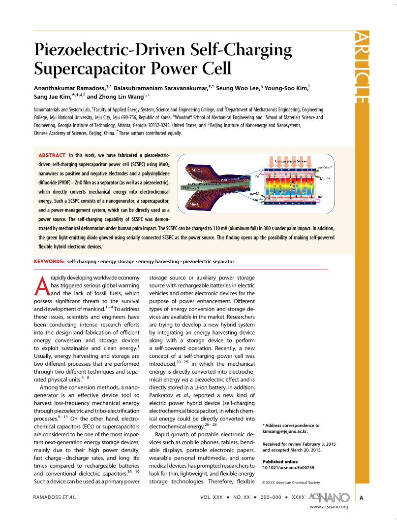
The fabricated SCSPC is schematically representedin Figure 1a. The device consists of three components:a positive electrode, a separator, and a negative elec-trode. The MnO2 nanowires/conductive carbon/binder
mixtures on aluminum foil were used as the positiveand negative electrodes. The PVDF�ZnO filmwas usedas a separator (as well as a piezoelectric) instead of aconventional separator. Further, Figure 1b shows theoptical images of fabricated SCSPC (aluminum foil andfabric).
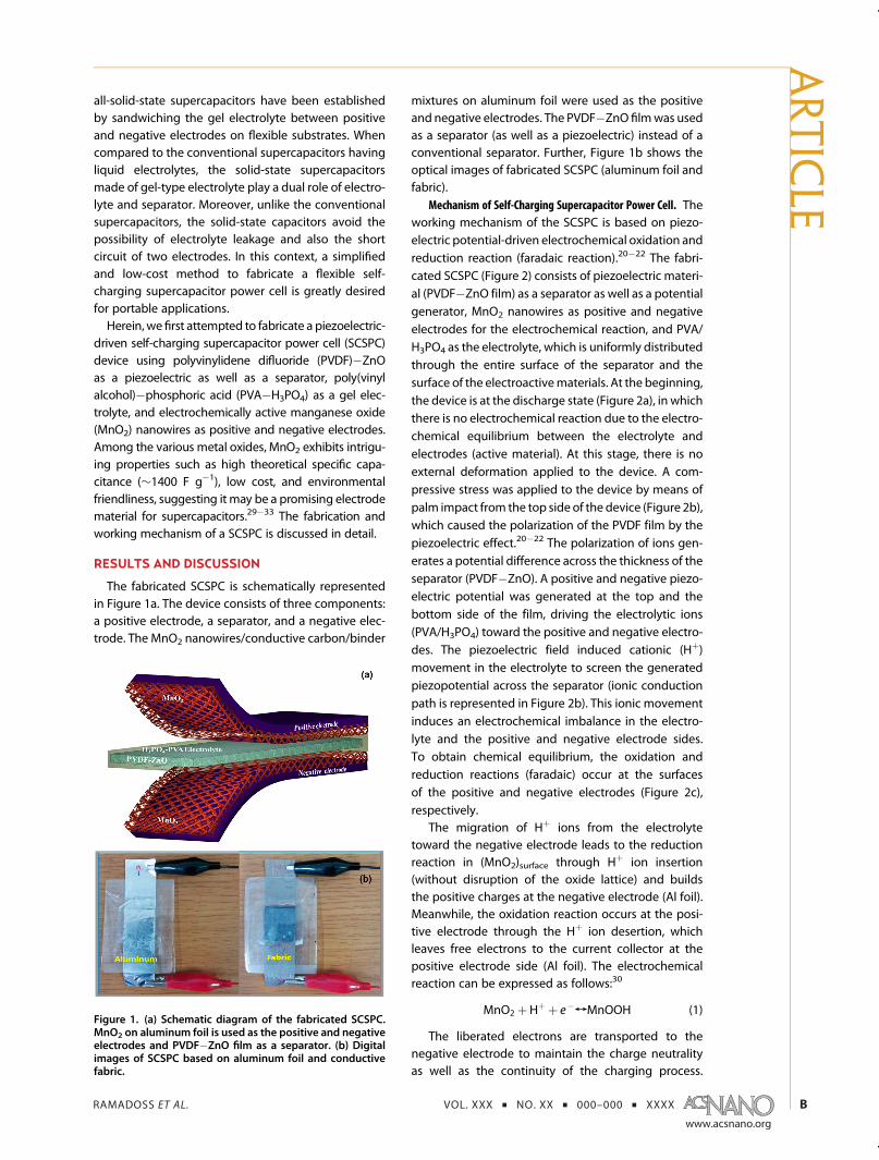
Mechanism of Self-Charging Supercapacitor Power Cell. Theworking mechanism of the SCSPC is based on piezo-electric potential-driven electrochemical oxidation andreduction reaction (faradaic reaction).20�22 The fabri-cated SCSPC (Figure 2) consists of piezoelectric materi-al (PVDF�ZnO film) as a separator as well as a potentialgenerator, MnO2 nanowires as positive and negativeelectrodes for the electrochemical reaction, and PVA/H3PO4 as the electrolyte, which is uniformly distributedthrough the entire surface of the separator and thesurface of the electroactivematerials. At the beginning,the device is at the discharge state (Figure 2a), in whichthere is no electrochemical reaction due to the electro-chemical equilibrium between the electrolyte andelectrodes (active material). At this stage, there is noexternal deformation applied to the device. A com-pressive stress was applied to the device by means ofpalm impact from the top side of the device (Figure 2b),which caused the polarization of the PVDF film by thepiezoelectric effect.20�22 The polarization of ions gen-erates a potential difference across the thickness of theseparator (PVDF�ZnO). A positive and negative piezo-electric potential was generated at the top and thebottom side of the film, driving the electrolytic ions(PVA/H3PO4) toward the positive and negative electro-des. The piezoelectric field induced cationic (Hþ)movement in the electrolyte to screen the generatedpiezopotential across the separator (ionic conductionpath is represented in Figure 2b). This ionic movementinduces an electrochemical imbalance in the electro-lyte and the positive and negative electrode sides.To obtain chemical equilibrium, the oxidation andreduction reactions (faradaic) occur at the surfacesof the positive and negative electrodes (Figure 2c),respectively.
The migration of Hþ ions from the electrolytetoward the negative electrode leads to the reductionreaction in (MnO2)surface through Hþ ion insertion(without disruption of the oxide lattice) and buildsthe positive charges at the negative electrode (Al foil).Meanwhile, the oxidation reaction occurs at the posi-tive electrode through the Hþ ion desertion, whichleaves free electrons to the current collector at thepositive electrode side (Al foil). The electrochemicalreaction can be expressed as follows:30
MnO2 þHþ þ e�TMnOOH (1)
The liberated electrons are transported to thenegative electrode to maintain the charge neutralityas well as the continuity of the charging process.
Figure 1. (a) Schematic diagram of the fabricated SCSPC.MnO2 on aluminum foil is used as the positive and negativeelectrodes and PVDF�ZnO film as a separator. (b) Digitalimages of SCSPC based on aluminum foil and conductivefabric.
ARTIC
LE
RAMADOSS ET AL. VOL. XXX ’ NO. XX ’ 000–000 ’ XXXX
www.acsnano.org
C
There are two possibilities for the electron transfer; oneis inside the SCSPC, and another is through the externalcircuit via a monitoring system (electrochemicalworkstation).20�22 In order to verify the electron flowin the SCSPC, we have directly measured the storedvoltage through a multimeter before and after com-pression without any external circuit/monitoringsystem. The open-circuit voltage was found to increaseunder repeated compression, clearly indicating theself-charging process of SCSPC. From this study,we concluded that the electron may flow through
the inside of the device. The detailed mechanisms ofelectron flow inside the SCSPC are still under debate.In such a SCSPC, the charging process involves cationinsertion into the negative electrode surface anddesertion from the positive electrode surface.
Under continuous compression force, the chargingprocess was repeated to attain chemical equilibriumof the two electrodes with piezoelectric potential;at this point, there is no further ionic polarization inthe device. This is the process of converting mechan-ical energy directly into electrochemical energy.
Figure 2. Working mechanism of the SCSPC driven by mechanical deformation. (a) Fabricated SCSPC at the dischargecondition. (b) Mechanical deformation is applied on the top of the device; it creates a piezoelectric field (potential) in thePVDF�ZnO separator film. (c) Under the piezoelectric field, the Hþ ions will migrate through the PVDF�ZnO separator in theelectrolyte to the negative electrode, leading to the corresponding charging reactions at the two electrodes. (d) Whenexternal deformation is released, there is no piezoelectric field at the separator, which breaks the attained chemicalequilibrium; it causes a reverse reaction on both sides of the electrode, and ions are relocated into the original position.(e) Completed self-charging cycle.
ARTIC
LE
RAMADOSS ET AL. VOL. XXX ’ NO. XX ’ 000–000 ’ XXXX
www.acsnano.org
D
When removing the compression force, piezoelectricpotential disappeared in the PVDF film (Figure 2d); itbreaks the electrochemical equilibrium of the device.To compensate, a small amount of ions will move back,indicating the completion of the charging cycle. Whena charging cycle is completed through the electro-chemical reaction (Figure 2e), a small oxidation andreduction occurred at the positive and negative elec-trode surfaces. With continuing applied force to thedevice, the charging cycle is repeated, which resultsin a conversion of mechanical energy directly intoelectrochemical energy. From the above discussion, itcould be argued that there are three main processesoccurring in the self-charging process: the generationof piezoelectric potential on a PVDF�ZnO film bypalm impact, the migration of ions toward electrodesthrough an ionic conduction path, and the reduction(negative electrode) and oxidation (positive electrode)reactions occurring at MnO2 via insertion/desertionof Hþ ions.
The self-chargingmechanism can also be explainedby using the Nernst equation, which shows the rela-tionship between electrode potentials and Hþ con-centration.20,21,34 When the piezoelectric field isformed by external compression, Hþ ionsmigrate from
the positive (i.e., MnO2 in the oxidation process) to thenegative (i.e., MnO2 in the reduction process) elec-trode. As a consequence, the concentration of Hþ onthe oxidative electrode decreases and the increase inHþ concentration on the reductive electrode is simul-taneously constructed. As this change of Hþ concen-tration electrochemically causes the potential of thenegative electrode to be larger than that of the positiveelectrode, the device is finally self-charged by thechange of redox potential through the concentrationgradient of Hþ ions. The basic characteristics of theseparator and electrodematerials are discussed below.
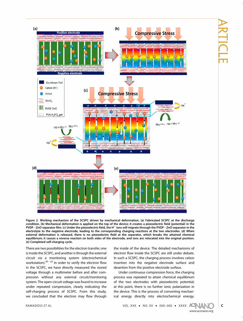
Characterization of Piezoelectric Materials (Separator andPower Source). The Fourier transform infrared (FT-IR)spectrum (Figure 3a) confirmed the presence of theβ-phase of PVDF at 512, 606, 838, and 1282 cm�2 andZnO stretching vibration mode peaks at 518 and420 cm�1; the remaining peaks were related to otherphases of PVDF.35 Figure 3b displays the field-emissionscanning electron microscopy (FE-SEM) image of thePVDF�ZnO separator, which confirms the homoge-neous distribution of ZnO nanowires in crystallinesuperulites of the PVDF matrix. Further, the nanogen-erator (energy harvesting) device was fabricated usingPVDF�ZnO film with Au as top and bottom electrodes.
Figure 3. (a) FT-IR spectrum and (b) FE-SEM image of the PVDF�ZnO separator. The β-phases of PVDF and ZnO stretchingvibrations are indexed. Open-circuit voltage (c) and short-circuit current (d) generated in the PVDF�ZnO separator. The insetshows thedigital imageof a fabricated PVDF�ZnOnanogenerator device. The averageoutput voltage and current is 5 V and2 μA,respectively. The output voltage and current of the device were not uniform, which may be attributed to different strain rates.
ARTIC
LE
RAMADOSS ET AL. VOL. XXX ’ NO. XX ’ 000–000 ’ XXXX
www.acsnano.org
E
Under the mechanical deformation, the piezoelectricpotential was generated on the surface of PVDF�ZnOfilm due to the polarization of PVDF as well as ZnO. Thegenerated output voltage is represented in Figure 3c.To compensate for the piezopotential, a transientflow of free electrons in an external circuit36 is shownin Figure 3d. The inset of Figure 3c shows the fabricatedPVDF�ZnO nanogenerator device. The presence ofZnO nanowires in the PVDF matrix induces the polar-ization of ions in the composite film without electricalpoling.37 From these results, we concluded that ourseparator can generate piezopotential in the fabri-cated SCSPC.
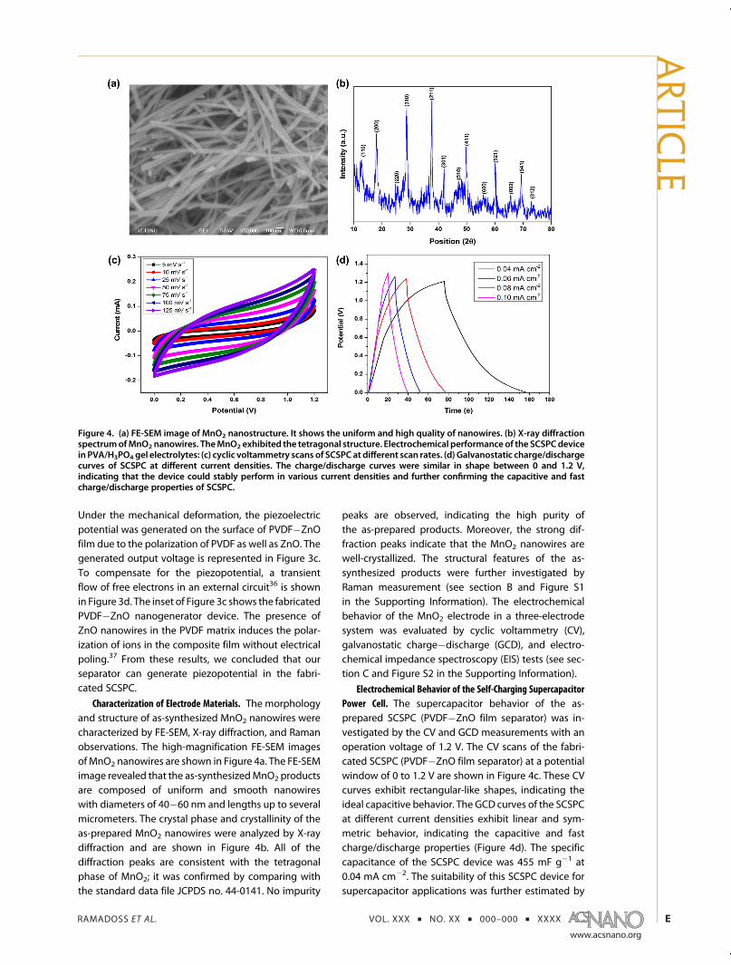
Characterization of Electrode Materials. The morphologyand structure of as-synthesized MnO2 nanowires werecharacterized by FE-SEM, X-ray diffraction, and Ramanobservations. The high-magnification FE-SEM imagesof MnO2 nanowires are shown in Figure 4a. The FE-SEMimage revealed that the as-synthesizedMnO2 productsare composed of uniform and smooth nanowireswith diameters of 40�60 nm and lengths up to severalmicrometers. The crystal phase and crystallinity of theas-prepared MnO2 nanowires were analyzed by X-raydiffraction and are shown in Figure 4b. All of thediffraction peaks are consistent with the tetragonalphase of MnO2; it was confirmed by comparing withthe standard data file JCPDS no. 44-0141. No impurity
peaks are observed, indicating the high purity ofthe as-prepared products. Moreover, the strong dif-fraction peaks indicate that the MnO2 nanowires arewell-crystallized. The structural features of the as-synthesized products were further investigated byRaman measurement (see section B and Figure S1in the Supporting Information). The electrochemicalbehavior of the MnO2 electrode in a three-electrodesystem was evaluated by cyclic voltammetry (CV),galvanostatic charge�discharge (GCD), and electro-chemical impedance spectroscopy (EIS) tests (see sec-tion C and Figure S2 in the Supporting Information).
Electrochemical Behavior of the Self-Charging SupercapacitorPower Cell. The supercapacitor behavior of the as-prepared SCSPC (PVDF�ZnO film separator) was in-vestigated by the CV and GCD measurements with anoperation voltage of 1.2 V. The CV scans of the fabri-cated SCSPC (PVDF�ZnO film separator) at a potentialwindow of 0 to 1.2 V are shown in Figure 4c. These CVcurves exhibit rectangular-like shapes, indicating theideal capacitive behavior. The GCD curves of the SCSPCat different current densities exhibit linear and sym-metric behavior, indicating the capacitive and fastcharge/discharge properties (Figure 4d). The specificcapacitance of the SCSPC device was 455 mF g�1 at0.04 mA cm�2. The suitability of this SCSPC device forsupercapacitor applications was further estimated by
Figure 4. (a) FE-SEM image of MnO2 nanostructure. It shows the uniform and high quality of nanowires. (b) X-ray diffractionspectrumofMnO2 nanowires. TheMnO2 exhibited the tetragonal structure. Electrochemical performance of the SCSPCdevicein PVA/H3PO4 gel electrolytes: (c) cyclic voltammetry scans of SCSPCat different scan rates. (d) Galvanostatic charge/dischargecurves of SCSPC at different current densities. The charge/discharge curves were similar in shape between 0 and 1.2 V,indicating that the device could stably perform in various current densities and further confirming the capacitive and fastcharge/discharge properties of SCSPC.
ARTIC
LE
RAMADOSS ET AL. VOL. XXX ’ NO. XX ’ 000–000 ’ XXXX
www.acsnano.org
F
examining its power and energy densities. The powerand energy densities were calculated using eqs 4 and 5and the charge/discharge curves at different currentdensities (see section G in the Supporting Information).The energy density of the SCSPC reached 91mWh kg�1
at a power density of 3.9 kW kg�1 and sustained58 mW h kg�1 at a power density of 9.9 kW kg�1. Afterthat, the leakage current of the device was measuredat a constant potential of 1.2 V for 8000 s, which isshown in Figure S3 (see section D in the SupportingInformation). At the beginning, the current wassuddenly dropped from 0.2 mA to 22 μA at 15 min,and then the leakage current was stabilized to ∼15 μAover 8000 s. The existence of a small leakage currentmay be due to the presence of impurities in electrodematerials or electrolyte of the fabricated SCSPCdevice.38�41 For reference, we have also tested theelectrochemical performance of an all-solid-state sym-metric supercapacitor based on filter paper separator(see section E and Figure S4a,b in the SupportingInformation). These results confirm that the proposedstructure of SCSPC is fully eligible to act as a super-capacitor system.
Self-Charging Performance of As-Fabricated SCSPC. Toshow the self-charging capability of the SCSPC
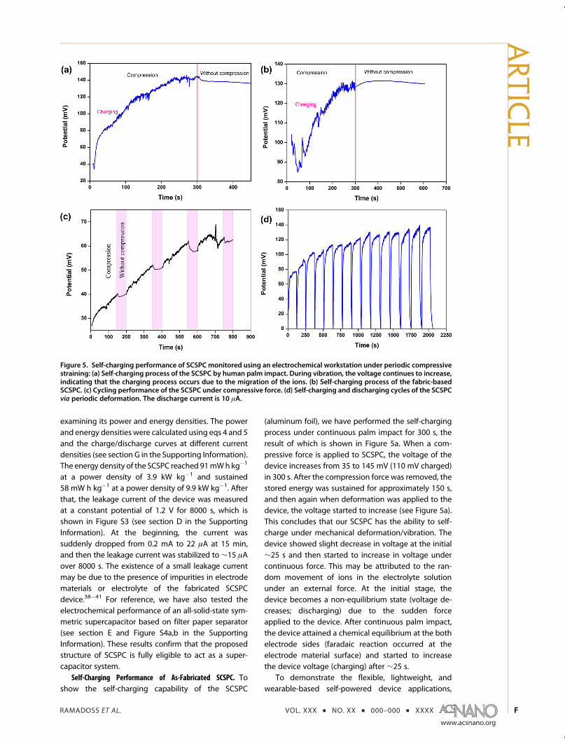
(aluminum foil), we have performed the self-chargingprocess under continuous palm impact for 300 s, theresult of which is shown in Figure 5a. When a com-pressive force is applied to SCSPC, the voltage of thedevice increases from 35 to 145 mV (110 mV charged)in 300 s. After the compression force was removed, thestored energy was sustained for approximately 150 s,and then again when deformation was applied to thedevice, the voltage started to increase (see Figure 5a).This concludes that our SCSPC has the ability to self-charge under mechanical deformation/vibration. Thedevice showed slight decrease in voltage at the initial∼25 s and then started to increase in voltage undercontinuous force. This may be attributed to the ran-dom movement of ions in the electrolyte solutionunder an external force. At the initial stage, thedevice becomes a non-equilibrium state (voltage de-creases; discharging) due to the sudden forceapplied to the device. After continuous palm impact,the device attained a chemical equilibrium at the bothelectrode sides (faradaic reaction occurred at theelectrode material surface) and started to increasethe device voltage (charging) after ∼25 s.
To demonstrate the flexible, lightweight, andwearable-based self-powered device applications,
Figure 5. Self-charging performance of SCSPC monitored using an electrochemical workstation under periodic compressivestraining: (a) Self-charging process of the SCSPC by human palm impact. During vibration, the voltage continues to increase,indicating that the charging process occurs due to the migration of the ions. (b) Self-charging process of the fabric-basedSCSPC. (c) Cycling performance of the SCSPC under compressive force. (d) Self-charging and discharging cycles of the SCSPCvia periodic deformation. The discharge current is 10 μA.
ARTIC
LE
RAMADOSS ET AL. VOL. XXX ’ NO. XX ’ 000–000 ’ XXXX
www.acsnano.org
G
we have fabricated and tested the self-chargingprocess of the fabric-based SCSPC under continuouspalm impact for 300 s. Figure 5b represents the self-charging process of the fabric-based SCSPC usingPVDF�ZnO separator films. Under continuous vibra-tion, fabric-based SCSPC showed an increase in voltage(charging) from 85 to 130mV (45mV charged) in 300 s.After the deformation was removed, the deviceshowed an increase in voltage for 50 s and thensustained the stored voltage for 250 s, which confirmthe self-charging capability of the as-fabricated fabric-based SCSPC. The increase in voltage was observedafter deformation, which may be due to the vibrationthat continued for a few seconds after deformation andthe light weight of the fabricated fabric-based SCSPC.Both devices showed increased voltage (charging)under the continuous force, confirming the self-charging performance of the SCSPC.
The self-charging performance of the devicemainlydepends on applied compressive force. To verify that,we have studied the self-charging performance ofSCSPC under various compressive force conditions.Varied compressive force of approximately 9.8, 12.2,14.9, and 18.8 N was applied through a human hand(using a metal cylinder). Figure S5 shows the self-charging and discharging cycles under differentcompressive stress (see section F in the SupportingInformation). When the applied force to SCSPCincreased, the self-charging result is enhanced. Theenhancement in the self-charging process is due tothe increase in piezopotential with the higher appliedstrain (compressive force). After the self-chargingprocess, the device was discharged back to its originalvoltage under a constant discharge current of 1 μA.These results confirmed that the self-charging processis due to the piezoelectric effect.
The cycling performance of the fabricated SCSPCwas performed under a compressive force. As shownin Figure 5c, the voltage of the device increased(self-charging) under the compressive force (∼9.8 N)applied to the device for 150 s. After the self-chargingprocess, the device sustained the charged voltage(highlighted in magenta color) for 50 s. Approximately,the SCSPC stored 15 mV in 150 s under compressiveforce. When the compressive force is repeated, thedevice starts to self-charge, confirming the repeatabil-ity (cycling performance) of the fabricated device.Further, Figure 5d shows the self-charging processand the discharging at a constant current of 10 μAfor 15 cycles. The voltage of the device was increasedunder the compressive strain (∼18.8 N for 120 s), andthen the device was back to its original voltage undera constant discharge current. The average self-chargevoltage of the device was 110 mV in 120 s undercompressive force. In addition, the specific capacitanceof the SCSPC can be calculated using the dischargecurrent, discharge time, and self-charged voltage
(voltage window). The calculated device capacitancewas 0.2575 F g�1 (257 mF g�1). The increasing voltagetrend was observed due the variation of applyingcompressive force (through human hand for which itwas difficult to control the input force), and then aftera few cycles, the device attained a stabilized state.This result confirms the better cycling performance(repeatability) of the fabricated SCSPC. Besides, wehave checked the self-charging process of SCSPC con-nected to the opposite sign (polarity change), which isdisplayed in Figure S6 (see section F in the SupportingInformation). Under vibration, the voltage of the deviceincreased from 105 to 140 mV at a negative directionin 300 s. After deformation, the device sustained thestored energy for 100 s. This also confirms the self-charging performance of the SCSPC.
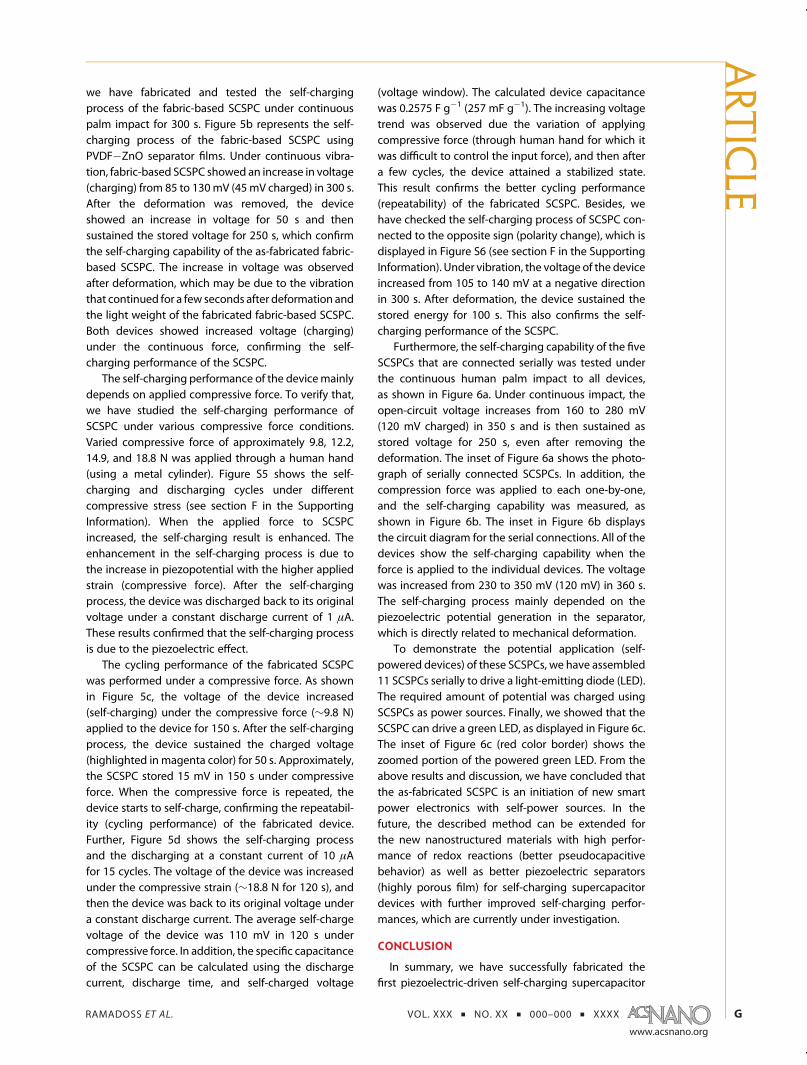
Furthermore, the self-charging capability of the fiveSCSPCs that are connected serially was tested underthe continuous human palm impact to all devices,as shown in Figure 6a. Under continuous impact, theopen-circuit voltage increases from 160 to 280 mV(120 mV charged) in 350 s and is then sustained asstored voltage for 250 s, even after removing thedeformation. The inset of Figure 6a shows the photo-graph of serially connected SCSPCs. In addition, thecompression force was applied to each one-by-one,and the self-charging capability was measured, asshown in Figure 6b. The inset in Figure 6b displaysthe circuit diagram for the serial connections. All of thedevices show the self-charging capability when theforce is applied to the individual devices. The voltagewas increased from 230 to 350 mV (120 mV) in 360 s.The self-charging process mainly depended on thepiezoelectric potential generation in the separator,which is directly related to mechanical deformation.
To demonstrate the potential application (self-powered devices) of these SCSPCs, we have assembled11 SCSPCs serially to drive a light-emitting diode (LED).The required amount of potential was charged usingSCSPCs as power sources. Finally, we showed that theSCSPC can drive a green LED, as displayed in Figure 6c.The inset of Figure 6c (red color border) shows thezoomed portion of the powered green LED. From theabove results and discussion, we have concluded thatthe as-fabricated SCSPC is an initiation of new smartpower electronics with self-power sources. In thefuture, the described method can be extended forthe new nanostructured materials with high perfor-mance of redox reactions (better pseudocapacitivebehavior) as well as better piezoelectric separators(highly porous film) for self-charging supercapacitordevices with further improved self-charging perfor-mances, which are currently under investigation.
CONCLUSION
In summary, we have successfully fabricated thefirst piezoelectric-driven self-charging supercapacitor
ARTIC
LE
RAMADOSS ET AL. VOL. XXX ’ NO. XX ’ 000–000 ’ XXXX
www.acsnano.org
H
power cell that consists of a PVDF�ZnO separator(piezoelectric nanogenerator) and MnO2 nanowiresused as the positive and negative electrodes (super-capacitor), which can be used to simultaneously har-vest and store the mechanical energy to electroche-mical energy. The SCSPC exhibited the self-chargingcapability under palm impact (aluminum-foil-based
SCSPC = 110 mV for 300 s; fabric-based SCSPC =45 mV for 300 s). Further, the green LED was operatedusing serially connected SCSPCs as the power source.The SCSPCs provide a new promising direction insupercapacitor research for the development of next-generation self-powered sustainable power sourcesfor wearable and flexible electronic devices.
EXPERIMENTAL SECTIONFabrication of a Self-Charging Supercapacitor Power Cell. The MnO2
nanowires were synthesized by a hydrothermal method (seesection A in the Supporting Information). The working electro-des (MnO2) were prepared by mixing 80 wt % of activematerials, 10 wt % of carbon black, and 10 wt % of PVDF inN-methylpyrrolidinone, and this slurry was pasted on aluminumfoil as well as conductive fabric and then heat-treated at 100 �Cunder vacuum overnight. Then the SCSPC was assembled bytwo-piece MnO2 (positive and negative) electrodes on alumi-num foil with PVA/H3PO4 gel electrolyte separator (PVDF�ZnO)in the middle. The assembled power cell was further dried atroom temperature for 12 h. Here, PVDF�ZnO acts as a separatoras well as a power source (piezoelectric effect). The PVDF�ZnOfilm separator was prepared by a solution-casting method ina ratio of 1:0.1 (PVDF/ZnO) in dimethylformamide. The PVA/H3PO4 gel electrolyte was prepared by mixing 3 g of PVA in30 mL of deionized water at 95 �C with stirring. After, the PVAwas completely dissolved, and 3 g of H3PO4 was added into thePVA solution under vigorous stirring until it formed a homo-geneous sticky solution. Then the solution was cooled at roomtemperature, and the solution became a clear and transparent
gel. Prior to assembly, the electrodes and the separator wereimmersed in PVA/H3PO4 gel electrolyte for 5 min and thenassembled one-by-one and kept at room temperature for 12 hto vaporize the excess water present in the electrolyte.
Characterization of the Self-Charging Supercapacitor Power Cell. Thestructure of the samples was characterized by a Rigaku X-raydiffractometer and a LabRam HR800 micro-Raman spectro-scope (Horiba Jobin-Yvon, France). The morphology of thesamples was investigated using FE-SEM (JSM-6700F, JEOL Ltd.,2 kV). The electrochemical and self-charging performancesof the as-prepared electrodes were investigated using anAUTOLAB PGSTAT302N electrochemical workstation.
Conflict of Interest: The authors declare no competingfinancial interest.
Acknowledgment. This research was supported by the BasicScience Research Program through the National ResearchFoundation of Korea (NRF) funded by the Ministry of Science,ICT & Future Planning (2013R1A2A2A01068926).
Supporting Information Available: Additional discussionsand figures of the structure and electrochemical properties ofMnO2 nanowires, self-charging and discharging performance
Figure 6. Self-charging performance of serially connected SCSPC: (a) self-charging process of the serially connected fiveSCSPCs under periodic compressive strain given by human palm impact to the whole devices. Inset shows a photograph ofthe serially connected SCSPCs. (b) Self-charging process of the serially connected five SCSPCs under periodic compressivestraining given by human palm impact to the each device for a 60 s interval. Inset shows the circuit diagram of serialconnection. (c) Operation of green light-emitting diode using serially connected SCSPCs as the power source.
ARTIC
LE
RAMADOSS ET AL. VOL. XXX ’ NO. XX ’ 000–000 ’ XXXX
www.acsnano.org
I
of SCSPCs at different applied forces, and self-charging per-formance of SCSPCs at reverse connection. This material isavailable free of charge via the Internet at http://pubs.acs.org.
REFERENCES AND NOTES1. Yu, X.; Lu, B.; Xu, Z. Super Long-Life Supercapacitors Based
on the Construction of Nanohoneycomb-like StronglyCoupled CoMoO4-3D Graphene Hybrid Electrodes. Adv.Mater. 2014, 26, 1044–1051.
2. Wang, H.; Dai, H. Strongly Coupled Inorganic�Nano-Carbon Hybrid Materials for Energy Storage. Chem. Soc.Rev. 2013, 42, 3088–3113.
3. Rosa, E. A.; Dietz, T. HumanDrivers of National Greenhouse-Gas Emissions. Nat. Clim. Change 2012, 2, 581–586.
4. Chu, S.; Majumdar, A. Opportunities and Challenges for aSustainable Energy Future. Nature 2012, 488, 294–303.
5. Arico, A. S.; Bruce, P.; Scrosati, B.; Tarascon, J. M.; VanSchalkwijk, W. Nanostructured Materials for AdvancedEnergy Conversion and Storage Devices. Nat. Mater.2005, 4, 366–377.
6. Tarascon, J. M.; Armand, M. Review Article Issues andChallenges Facing Rechargeable Lithium Batteries. Nature2001, 414, 359–367.
7. Wang, Z. L. Towards Self-Powered Nanosystems: FromNanogenerators to Nanopiezotronics. Adv. Funct. Mater.2008, 18, 3553–3567.
8. Hu, Y. F.; Zhang, Y.; Xu, C.; Lin, L.; Snyder, R. L.; Wang, Z. L.Self-Powered System with Wireless Data Transmission.Nano Lett. 2011, 11, 2572–2577.
9. Yang, R. S.; Qin, Y.; Dai, L. M.; Wang, Z. L. Power Generationwith Laterally Packaged Piezoelectric Fine Wires. Nat.Nanotechnol. 2009, 4, 34–39.
10. Saravanakumar, B.; Mohan, R.; Thiyagarajan, K.; Kim, S. J.Fabrication of a ZnO Nanogenerator for Eco-FriendlyBiomechanical Energy Harvesting. RSC Adv. 2013, 3,16646–16656.
11. Wang, Z. L.; Song, J. H. Piezoelectric Nanogenerators BasedonZincOxideNanowire Arrays. Science 2006, 312, 242–246.
12. Wang, Z. L. Self-Powered Nanotech. Sci. Am. 2008, 298,82–87.
13. Wang, Z. L.; Wu, W. Nanotechnology-Enabled EnergyHarvesting for Self-Powered Micro-/Nanosystems. Angew.Chem., Int. Ed. 2012, 51, 11700–11721.
14. Fan, F. R.; Tian, Z. Q.; Wang, Z. L. Flexible TriboelectricGenerator. Nano Energy 2012, 1, 328–334.
15. Wang, Z. L. Triboelectric Nanogenerators as New EnergyTechnology for Self-Powered Systems and as ActiveMechanical and Chemical Sensors. ACS Nano 2013, 7,9533–9557.
16. Zhu, Y.; Murali, S.; Stoller, M. D.; Ganesh, K. G.; Cai, W.;Ferreira, P. J.; Pirkle, A.;Wallace, R.M.; Cychosz, K. A.; Thommes,M.; et al. Carbon-Based Supercapacitors Produced by Activa-tion of Graphene. Science 2011, 332, 1537–1541.
17. Liu, C.; Yu, Z.; Neff, D.; Zhamu, A.; Jang, B. Z. Graphene-Based Supercapacitor with an Ultrahigh Energy Density.Nano Lett. 2010, 10, 4863–4868.
18. Chou, J. C.; Chen, Y. L.; Yang, M. H.; Chen, Y. Z.; Lai, C. C.;Chiu, H. T.; Lee, C. Y.; Chueh, Y. L.; Gan, J. Y. RuO2/MnO2
Core�Shell Nanorods for Supercapacitors. J. Mater. Chem.A 2013, 1, 8753–8758.
19. Lee, M.; Balasingam, S. K.; Jeong, H. Y.; Hong, W. G.;Kim, B. H.; Jun, Y. One-Step Hydrothermal Synthesis ofGraphene Decorated V2O5 Nanobelts for Enhanced Elec-trochemical Energy Storage. Sci. Rep. 2015, 5, 8151–8158.
20. Xue, X.; Wang, S.; Guo, W.; Zhang, Y.; Wang, Z. L. Hybridiz-ing Energy Conversion and Storage in a Mechanical-to-Electrochemical Process for Self-Charging Power Cell.Nano Lett. 2012, 12, 5048–5054.
21. Xue, X.; Deng, P.; Yuan, S.; Nie, Y.; He, B.; Xing, L.; Zhang, Y.CuO/PVDF Nanocomposite Anode for a Piezo-Driven Self-Charging Lithium Battery. Energy Environ. Sci. 2013, 6,2615–2620.
22. Xue, X.; Deng, P.; He, B.; Nie, Y.; Xing, L.; Zhang, Y.; Wang,Z. L. Flexible Self-Charging Power Cell for One-Step Energy
Conversion and Storage. Adv. Energy Mater. 2014, 4,1301329.
23. Zhang, Y.; Zhang, Y.; Xue, X.; Cui, C.; He, B.; Nie, Y.; Deng, P.;Wang, Z. L. PVDF�PZT Nanocomposite Film Based Self-Charging Power Cell. Nanotechnology 2014, 25, 105401–105407.
24. Xing, L.; Nie, Y.; Xue, X.; Zhang, Y. PVDF MesoporousNanostructures as the Piezo-Separator for a Self-ChargingPower Cell. Nano Energy 2014, 10, 44–52.
25. Kim, Y. S.; Xie, Y.; Wen, X.; Wang, S.; Kim, S. J.; Song, H. K.;Wang, Z. L. Highly Porous Piezoelectric PVDF Membraneas Effective Lithium Ion Transfer Channels for EnhancedSelf-Charging Power Cell. Nano Energy 2015, 10.1016/j.nanoen.2015.01.006.
26. Pankratov, D.; Falkman, P.; Blum, Z.; Shleev, S. A HybridElectric Power Device for Simultaneous Generation andStorage of Electric Energy. Energy Environ. Sci. 2014, 7,989–993.
27. Pankratov, D.; Blum, Z.; Shleev, S. Hybrid Electric PowerBiodevices. ChemElectroChem 2014, 1, 1798–1807.
28. Pankratov, D.; Blum, Z.; Suyatin, D. B.; Popov, V. O.;Shleev, S. Self-Charging Electrochemical Biocapacitor.ChemElectroChem 2014, 1, 343–346.
29. Yuan, C.; Hou, L.; Yang, L.; Li, D.; Shen, L.; Zhang, F.; Zhang,X. Facile Interfacial Synthesis of Flower-like Hierarchicala-MnO2 Sub-microspherical Superstructures Constructedby Two-Dimension Mesoporous Nanosheets and TheirApplication in Electrochemical Capacitors. J. Mater. Chem.2011, 21, 16035–16041.
30. Yu, P.; Zhang, X.; Wang, D. L.; Wang, L.; Ma, Y. W. Shape-Controlled Synthesis of 3D Hierarchical MnO2 Nanostruc-tures for Electrochemical Supercapacitors. Cryst. GrowthDes. 2009, 9, 528–533.
31. Sung, D. Y.; Kim, I. Y.; Kim, T. W.; Song, M. S.; Hwang, S. J.Room Temperature Synthesis Routes to the 2D Nano-plates and 1D Nanowires/Nanorods of Manganese Oxideswith Highly Stable Pseudocapacitance Behaviors. J. Phys.Chem. C 2011, 115, 13171–13179.
32. Ramadoss, A.; Kim, S. J. Hierarchically StructuredTiO2@MnO2 Nanowall Arrays as Potential ElectrodeMaterial for High-Performance Supercapacitors. Int. J.Hydrogen Energy 2014, 39, 12201–12212.
33. Wei, W.; Cui, X.; Chen, W.; Ivey, D. J. Manganese Oxide-Based Materials as Electrochemical Supercapacitor Elec-trodes. Chem. Soc. Rev. 2011, 40, 1697–1721.
34. Bard, A. J.; Faulkner, L. R. Electrochemical Methods: Funda-mentals and Applications, 2nd ed.; John Wiley & Sons, Inc.:New York, 2001.
35. Yu, H.; Huang, T.; Lu, M.; Mao, M.; Zhang, Q.; Wang, H.Enhanced Power Output of an Electrospun PVDF/MWCNTs-Based Nanogenerator by Tuning Its Conductiv-ity. Nanotechnology 2013, 24, 405401–405409.
36. Lee, M.; Chen, C. Y.; Wang, S.; Cha, S. N.; Park, Y. J.; Kim, J. M.;Chou, L. J.; Wang, Z. L. A Hybrid Piezoelectric Structure forWearable Nanogenerators. Adv. Mater. 2012, 24, 1759–1764.
37. Saravanakumar, B.; Soyoon, S.; Kim, S. J. Self-Powered pHSensor Based on a Flexible Organic�Inorganic HybridComposite Nanogenerator. ACS Appl. Mater. Interfaces2014, 6, 13716–13723.
38. Yuan, L.; Lu, X. H.; Xiao, X.; Zhai, T.; Dai, J.; Zhang, F.; Hu, B.;Wang, X.; Gong, L.; Chen, J.; et al. Flexible Solid-StateSupercapacitors Based on Carbon Nanoparticles/MnO2
Nanorods Hybrid Structure. ACS Nano 2012, 6, 656–661.39. Meng, C.; Liu, C.; Chen, L.; Hu, C.; Fan, S. Highly Flexible and
All-Solid-State Paper-like Polymer Supercapacitors. NanoLett. 2010, 10, 4025–4031.
40. Xiong, G.; Meng, C.; Reifenberger, R. G.; Irazoqui, P. P.;Fisher, T. S. Graphitic Petal Electrodes for All-Solid-StateFlexible Supercapacitors. Adv. Energy Mater. 2014, 4,1300515–1300524.
41. Yang, P.; Xiao, X.; Li, Y.; Ding, Y.; Qiang, P.; Tan, X.; Mai, W.;Lin, Z.; Wu, W.; Li, T.; et al. Hydrogenated ZnO Core�ShellNanocables for Flexible Supercapacitors and Self-PoweredSystems. ACS Nano 2013, 7, 2617–2626.
ARTIC
LE