piezoelectric materials chris petorak reu dr. bowman and j.jones
Post on 19-Dec-2015
225 views
TRANSCRIPT
Piezoelectric Materials
Chris Petorak
REU
Dr. Bowman and J.Jones

Piezoelectric Materials
• Below Curie Temp• Perovskite unit cell • Unit electric dipole• Poling of dipoles in
single direction allows for piezoelectric properties
Piezoelectric Properties
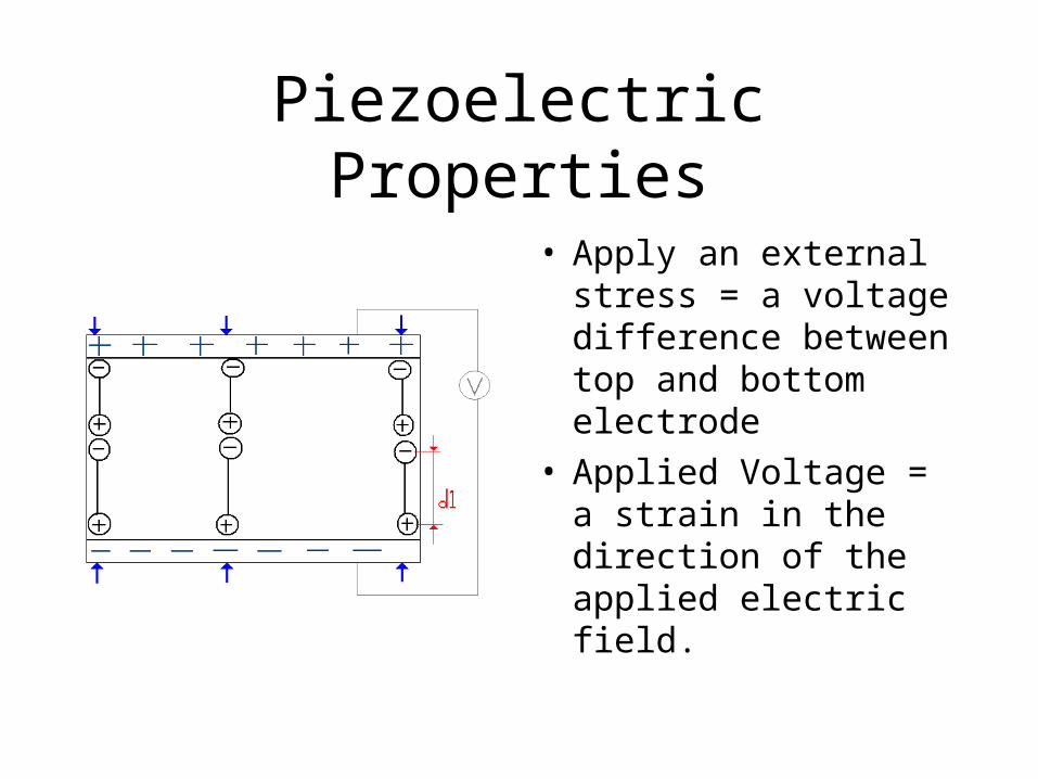
• Apply an external stress = a voltage difference between top and bottom electrode
• Applied Voltage = a strain in the direction of the applied electric field.
Common Applications
• Sensors ex. Microphones and
Hydrophones
• Actuators
• Ultrasound technology

Fatigue of Ferroelectric Properties
• Narrowing of Hystersis loop
• Decreasing switchable polarization and d33
• Increasing # of cycles leads to greater reduction in ferroelectric properties
Zhang,N. Li,L. Gui,Z. Degredation of piezoelectric and dielectirc relaxation properties due to electric faitgue in PLZT ferroelectric capacitors

Domain Wall Pinning
• Oxygen Vacancies
• Results in Space Charge
• Space Charge accumulate to pin domain walls
• Reduce domain wall mobility
• Therefore reducing switch able polarization

Cycling Setup Considerations
• Electrical Loading• Hystersis loop • Apply alternating field• 180 domain
reorientation• Parallel plate capacitor • Lower Cost & Easier
to find Parts
• Compressive Loading• Stress vs. Strain• Apply stress to get 1%
deformation• 90 domain
reorientation• Compressive jig setup
highly sensitive and expensive

Cycling Setup Considerations
• High Voltage• Electric field higher
than Ec • Closer to saturation
the greater the fatigue
• Low Frequency• More time for E to
affect domains and difficult movement
• Domains become set = greater internal stresses to be overcome in reverse cycle

Building the Setup
• 1st Setup – DC power source 1.4kV/mm Sinusoidal oscillator
20Hz
• 2nd Setup – AC power source 60Hz Tube transformer
1.4kV/mm Variac
• Parallel plate capacitor setup under constant stress

Building the Setup

Trouble Shooting
• Calibration of variable autotransformer indirectly
• Linear relationship is found
• E = V/t0-5
5-10
10-15

Geometry
K181 Sample #71,72
Sample #33,44
Sample #3,5
K182
Sample #13,15
Initial Run
180
165
d1_failure 330
d1_failure 331
2 1041 Cycles_failure
1 10 100 1 103
1 104
1 105
165
170
175
180
# 33 1.4kV/mm#44 1.4 kV/mm
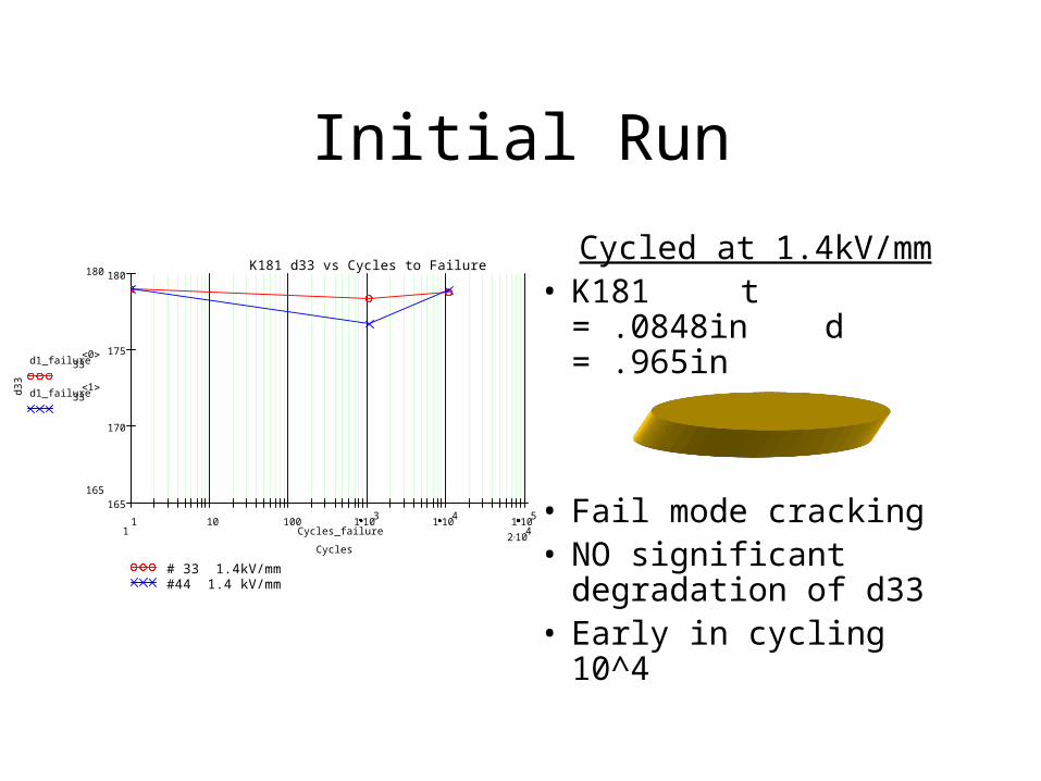
K181 d33 vs Cycles to Failure
Cycles
d33
Cycled at 1.4kV/mm• K181 t = .0848in
d = .965in
• Fail mode cracking• NO significant
degradation of d33• Early in cycling 10^4

Second Run
212.3
2.7
d 33_5i j
p C
N
d 33_2i j
p C
N
d 33_215k
p C
N
d 33_213k
p C
N
1 1061 Cycles
i j Cyclesi j Failure_2
k
1 10 100 1 103
1 104
1 105
1 106
62.5
125
187.5
250
K181 #5K181 #2K182 #15K182 #13
1.2kV/mm Cycling Field
Cycles
d33
(p*C
/N)
Cycled 1.2kV/mm• K182 Fail
t = .0839ind = .843in
• K181 degrades
t = .0848ind = .841in
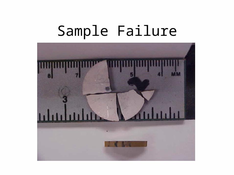
Sample Failure

Trouble Shooting
• Time constraints K182 is abandoned to focus further on K181
• Current is candidate for FailureOhms law I = V/R
• Resistance is geometry dependent - longer length = higher R
- smaller area = higher R

Last Run
210
175
d1_failure 332
d1 33_72k
1.72 1041 Cycles_failure Failure_72
k
1 10 100 1 103
1 104
1 105
180
190
200
210
K181 #71 @1.4kV/mmK181 #72 @1.24kV/mm
Cycles
d33
(p*C
/N)
• Area Considerations = R*A/t• E = V/t• E*t = I* *t/A• A increases so does I
because is independent of geometry

Area and Current
• Current Macrolevel – seems to support theory
• Current Microlevel – current/unit area leaves a hole in argument.
• Probability of defects in greater in larger Volume
• Porosity

Recommendations
• Cycle further samplesLarge A large t at 1.2kV/mm
Small A large t at 1.4kV/mm
• Establish relationship for sample’s R at low I and low V. Use this to predict the Current flow through at high voltage.