pik-20d fatigue evaluation 20161004 - trafi.fi · pik-20d fatigue evaluation ... mt horizontal tail...
TRANSCRIPT

PIK-20D Fatigue Evaluation Erkki Soinne
Trafi Research Reports
Trafin tutkimuksia
Trafis undersökningsrapporter 7/2015 Amendment A1

Trafi research report 7/2015
1
PIK-20D Fatigue Evaluation
Erkki Soinne
Finnish Transport Safety Agency
Liikenteen turvallisuusvirasto Trafi
Trafiksäkerhetsverket Trafi
Helsinki Helsingfors 2015
ISBN 978-952-311-073-1
ISSN 2342-0294

Trafi research report 7/2015
2
FOREWORD
This research report is focused on the fatigue evaluation of the
glider PIK-20D. It forms the basis for a special inspection request-
ed by EASA.
During the investigation valuable help and advice was obtained by
the former staff of Eiriavion Oy, Markku Hiedanpää, Hannu Korho-
nen and Stefan Nyström, which designed and produced the air-
craft. Valuable help and advice was also obtained from the former
and present people of Laboratory of light structures at Helsinki
University of Technology (now Aalto–University), namely Timo
Brander, Heikki Perälä, Olli Saarela and Pekka Tammi, who were
involved in the material, static and fatigue testing of the aircraft.
Special thanks go to Otto Kuosmanen and Jani Kosonen for check-
ing the fatigue calculations and proof reading the text. Other col-
leagues at Trafi have given valuable comments on the inspection
program.
I am also grateful for learning fatigue analysis at Saab and work-
ing with such nice aircraft as Saab 340, Saab 2000 and 39 Griffon.
Helsinki, November 15th 2015
Erkki Soinne
Chief Adviser, Aeronautics
Finnish Transport Safety Agency, Trafi
In this version some typographical errors have been corrected and
amendment A1 has been added on page 42. Oct 4th 2016 ES.

Trafi research report 7/2015
3
Index
Abstract
Nomenclature ...................................................................................... 5
1 Introduction .................................................................................... 6
2 PIK-20D structure ........................................................................... 8
3 Calculation of fatigue life .............................................................. 11
4 Saab fatigue methodology ............................................................. 20
5 Wing spar cap fatigue ................................................................... 22
6 Wing spar web fatigue .................................................................. 25
7 Wing fatigue test ........................................................................... 30
8 Metal brackets fatigue ................................................................... 34
8.1 Wing spar end main fitting ....................................................... 34
8.2 Wing bevel pins ...................................................................... 37
8.3 Tailplane fitting loads .............................................................. 40
8.4 Tailplane forward fitting .......................................................... 42
8.5 Fin forward fitting ................................................................... 47
8.6 Fin aft fitting .......................................................................... 50
9 Composite structure ...................................................................... 52
10 Wing metal parts ........................................................................... 56
11 Fuselage and tail metal parts ........................................................ 59
12 Inspection program ....................................................................... 64
References ......................................................................................... 67
Appendix 1 Wing spar cap fatigue calculation .................................. 69
Appendix 2 Wing web fatigue calculation ......................................... 70
Appendix 3 Wing spar end main fitting fatigue calculation .............. 71
Appendix 4 Fatigue inspection program ........................................... 73

Trafi research report 7/2015
4
ABSTRACT
European Aviation Safety Agency EASA has requested Trafi to es-
tablish a special inspection program for PIK-20 series aircraft. This
report explains the reasoning for the inspection interval and the
inspection objects. As a basis for this the stress calculations, fa-
tigue and material tests and drawings of PIK-20D were reviewed. A
noticeable effort was made to find and collect all relevant material
data established in the 1970s. Also relevant MSc thesis documents
were collected and reviewed as appropriate. Contradictory results
in fatigue calculations were checked and the results were trans-formed to be consistent with the Kossira-Reinke spectrum (includ-
ing aerobatics) which has become a standard in Europe. At present
the report contains the most complete overview on PIK-20D fa-
tigue and shows that there are no known fatigue problems.

Trafi research report 7/2015
5
Nomenclature
a distance; material parameter
b distance D allowed cumulative fatigue sum
E modulus of elasticity
fN scatter factor in life
fS scatter factor in stress
Fa load amplitude
Ftu tensile ultimate strength
Fty tensile yield strength
G shear modulus
h plate thickness
Kf fatigue notch factor
l effective width
m bending moment intensity; material parameter
Mt horizontal tail pitching moment n load factor; number of load cycles
N allowable number of load cycles
P point load; horizontal tail load
R stress ratio
T temperature
V stressed volume
Va maximum design maneuvering speed
VB maximum design speed in gusty weather
VD maximum design diving speed
α stress concentration factor
αt tail angle of attack
δ volume factor
δe elevator deflection
δf flap deflection
γ shear strain
ε strain
Θ&& pitching acceleration
κm surface roughness factor
κs surface treatment factor
λ material thickness
ν Poisson number
ρ notch radius
σ stress; standard deviation
σa stress amplitude
τ shear stress
ψ surface effect factor

Trafi research report 7/2015
6
1 Introduction
EASA has requested Trafi to establish a special inspection program for PIK-20 series
aircraft. This report explains the reasoning for the inspection interval and the in-
spection objects for PIK-20D.
PIK-20 and PIK-20D were originally certified in utility category according to OSTIV
Airworthiness Requirements For Sailplanes, September 1971 (ref. OSTIV), see ref.
PIK-20D SAS page 2. OSTIV requirements paragraph 4.18, Fatigue strength, state
that “The structure shall be designed, as far as practicable, to avoid points of stress
concentration where variable stresses above the fatigue limit are likely to occur in
normal service”. There is no requirement on performing fatigue calculations or fa-
tigue tests.
PIK-20D Type Certificate was issued by CAA Finland at September 21st 1976. The
tests and design work are summarized in ref. “Summary of the design work…”. Re-
garding fatigue the certification was based on the experience from PIK-20 and PIK-
20B. On PIK-20 there is a MSc thesis on the Material tests for Rütapox L02/L20
epoxy resin and Interglas glass fiber cloths (ref. Perälä “Theoretical and…”) and an-
other on PIK-20 wing static and dynamic tests (ref. Keturi). In the latter a fatigue
test was performed on the glass fiber wing. For the PIK-20B carbon fiber wing the
dimensioning is found in reference Perälä “PIK-20B Stress calculations…”. A number
of research reports on carbon fiber static and fatigue properties were written at the
university. The latest summary on fatigue properties is found in ref. Tammi. How-
ever, it was noticed that the results were conservative see ref. Perälä ”Bending fa-
tigue strength…”. Later on a fatigue test was performed on the PIK-20D wing to en-
able an increase of the strain level and weight savings through structural changes,
see references Nyström and Nyström & Mai. An approval of aerobatic flight was is-
sued for PIK-20D in 1994 with the loadings analyzed in ref. Vahtera.
PIK-20D was certified according to the OSTIV requirements without setting a limit
for the utilization life of the aircraft. The reference PIK-20D SAS says in Note 2 on
page 6 that “Inspections, Maintenance, Repairs, and Repaintings must be accom-
plished in accordance with Eiriavion Oy's PIK-20D Flight Manual Section 2 (Service
Manual) and Section 3 (Repair Manual)”. There is no inspection mentioned in the
manuals to prolong the aircraft life time. Consequently at present there is no legal
basis to require the sailplane owners to perform a special inspection to prolong the
life time.
Formerly there was a Finnish national Aviation Regulation AIR M6-1 Maintenance of
gliders and motor gliders (1995, in Finnish) requiring a special inspection on all
gliders, but the AR is revoked. There was also a national Advisory Circular Air T6-1
Minimum Maintenance Requirements for Sailplanes and Powered Sailplanes, but this
circular is also revoked. This AC required on all gliders a special inspection after
3000 FLH and thereafter every 1000 FLH or 5 years. There was no fatigue problem
initiating the requirement. The requirement was intended for wooden gliders, the
condition of which is more dependent on storage and humidity, but was unneces-
sarily applied also on all composite gliders. The fleet leading PIK-20D in Finland
(now at 4300 FLH) has passed several special inspections due to limited flight usage
at an interval of around 200 FLH. It seems that abroad PIK-20D has been flying
over 6000 FLH. Nothing fatigue related has been found in the PIK-20 special inspec-
tions.
At present there is no technical basis to require a special inspection as the fatigue
analysis shows an ample fatigue life and the special inspections have not given any
indication of a fatigue issue. However, fatigue is a common question for all aging

Trafi research report 7/2015
7
aircraft and it is wise to plan in advance for possible actions. The present report is
prepared to make a recommendation of the inspections needed in the future.

Trafi research report 7/2015
8
2 PIK-20D structure
PIK-20D sailplane, shown in Figure 1, has a monocoque composite fuselage and
wings and tail made of composite sandwich structure. The wings have an integral
wing spar as shown in Figure 2. The wing root area inner structure is shown in
Figure 3. The wings are connected with a main pin through the wing spars with the
fuselage hanging in four shear pins between the wings, see Figure 4.
Figure 1. PIK-20D in flight.
Figure 2. PIK-20 wing structure, ref. Lukkarinen page 32.

Trafi research report 7/2015
9
Figure 3. PIK-20D wing root area strucure FEM model,
ref. Lukkarinen page 33, 66.

Trafi research report 7/2015
10
Figure 4. PIK-20 wing/fuselage and horizontal/vertical tail joints.

Trafi research report 7/2015
11
3 Calculation of fatigue life
PIK-20 fuselage is critical in buckling and consequently the acting strains are so low
that the fuselage structure is not critical in fatigue. Due to minimum material thick-
nesses the sandwich structure of the tail is lightly loaded and not critical in fatigue.
Wing is the fatigue critical part and normally the wing spar under compression load
is generally assumed critical in fatigue, ref. Waibel page 58.
PIK-20D fatigue life has been calculated in references Lukkarinen and Lumppio. In
the following a detailed description is made on the calculations. Especially the fol-
lowing factors are studied here:
- load spectrum
- effect of aerobatic flight
- stress concentration
- material survivability and confidence limits
- effect of resin system and fiber type
- stress ratio R
- life factor
- cumulative damage sum D
The following loading spectra have been used in the fatigue analysis of PIK-20:
- Keturi
- Nyström
- Nyström with 44% increased strain levels
- Royal Melbourne Institute of Technology
- Franzmayer
- Kossira-Reinke
Keturi’s spectrum, which is based on the thesis work in ref. Valve, was used in the
first fatigue test on PIK-20, ref. Keturi. As Keturi’s spectrum was assessed quite
conservative Nyström’s spectrum was derived for the fatigue testing of the PIK-20D
with the carbon fibre spar caps. The gust loads in Nyström’s spectrum were derived
using power spectral density analysis. However, the spectrum that was actually
used for the fatigue test of PIK-20D was scaled up 44% to deliberately apply a very
conservative spectrum, ref. Lumppio page 134. The Royal Melbourne Institute of
Technology spectrum is based on flight measurements, ref. Patching & Wood page
2. The Franzmayer spectrum is an analytical spectrum derived for the first compo-
site sailplanes in the 1960s, ref. Lumppio page 122, 133. The Kossira-Reinke spec-
trum is based on flight load measurements.
The Kossira-Reinke –spectrum (see ref. Kossira & Reinke), also called as KoSMOS
cycle, has become a standard in Germany. In the derivation of the spectrum it be-
came clear that the usage of gliders in different parts of Germany was very differ-
ent. To cover all gliders with one spectrum, even two-seaters, an envelope was
formed to contain all kinds of operations:
- aircraft towing up to 700 m
- aircraft towing up to Flight Level 55
- winch launching
- landings
- flight training around the airfield
- cross country flying
- mountain flying
- wave flying
- aerobatics

Trafi research report 7/2015
12
The spectrum is based on flight load measurements, performed on a Janus –two-
seater. It is considered that the flight tests are representative for other sailplane
types too in spite of different pilot feel (stick force gradient etc), ref. Waibel page
57. The flight measurements also contained aerobatic maneuvers by 5 different pi-
lots performing spins, loops and stall turns, ref. Kossira & Reinke page 3 and 4.
Kossira -Reinke –spectrum is the only one in which aerobatic flight has been taken
into account. In the spectrum has been added 12,5% of aerobatics as the amount
of aerobatic flight on sailplanes is at maximum 10% according to Kossira & Reinke,
ref. Lukkarinen page 93.
In the measurement of the loads in the aerobatic maneuvers with the Janus glider it
was noticed, that the maximum loads reached a load factor of n=6,62 exceeding
the maximum value n=5,3 specified for Utility category gliders in the airworthiness
requirements, see ref. Kossira & Reinke page 73. The high values were experienced
in stall turn maneuvers, in which the turn was not performed perfectly, but the
speed was unintentionally increased somewhat before reaching a straight dive.
The maximum load factor of PIK-20D in Utility category at a maximum weight of
450 kg happens to be in a gust case n=6,62 due to a high value, chosen for the
maximum speed in gusty weather VB, ref. “Summary of the most severe …” page 4.
Hence PIK-20D has an inherent margin in load factor for unskilled aerobatic maneu-
vering. In the aerobatic category no water ballast is used and the selected maxi-
mum weight is reduced to 360 kg and the maximum load factor n=6,6, ref. Vahtera
page 9, 11. Consequently the maximum wing bending moment is reduced 12%, ref.
Vahtera p. 14. This means that PIK-20D is only moderately loaded in aerobatic
flight where the target load factors are 3,5…4 (looping and Cuban eight) and 4,5
(Immelman and Humpty-dumpty).
There are several comparisons of spectra in the thesis works of Lumppio and Luk-
karinen, one of which is shown in Figure 5. Nyström’s original and elevated spectra
have been converted to 6000 FLH for comparison with the Kossira-Reinke spectra.
As is seen in the figure Nyström’s original spectrum (green dotted symbos) fits fair-
ly well with the Kossira-Reinke spectrum without aerobatic flight (dark blue
Figure 5. Comparison of spectra, ref. Lukkarinen page 98.

Trafi research report 7/2015
13
diamond symbols). The Kossira-Reinke spectrum, in which 750 FLH (12,5%) of aer-
obatic flight has been added is shown with red square symbols. Nyström’s 44% ele-
vated spectrum (light blue triangular symbols) exceeds the amplitudes of the Kossi-
ra-Reinke spectrum, which includes also aerobatic flight, at almost all load factor
levels. This is not quite true at very low load factors n=-1,0…0 where it really does
not matter. It seems that the Kossira-Reinke spectrum’s maximum number of load
cycles around 1g level flight is higher than in the theoretically derived Franzmeyer
and Nyström spectra. This seems to be due the flight measurements and extrapola-
tion to the entire spectrum time. The high number of low load cycles emerges from
mountain flying, see ref. Kossira & Reinke fig. 145.
In overall comparison the Kossira-Reinke spectrum including aerobatics seems to be
quite conservative. The spectrum is considered to be “very much to the conserva-
tive side despite an omission of low amplitude cycles”, ref. Waibel page 57. Ref.
Kossira & Reinke refer on page 66 to a fatigue test from 1977 indicating that trun-
cation of low level cycles in a spectrum may be non-conservative. Newer literature,
such as ref. Tomblin & Seneviratne page 86 indicates, that a spectrum for compo-
site aircraft can be truncated below 30% design limit load without significant effect
on fatigue.
The main reason for the conservatism in the Kossira-Reinke spectrum is, that it is
intended to cover all types of operations and all types of gliders. The spectrum is an
envelope of all types of operations. For example the 750 FLH of aerobatic flight has
been added into the spectrum without taking anything else away. In this report the
Kossira-Reinke spectrum with 750 FLH of aerobatics is chosen as the basis for the
fatigue life assessment of PIK-20 to treat it in the same way as other gliders.
Lukkarinen has investigated the effect of stress concentration on the wing spar cap
strains due to the wing V-angle and the abrupt change in stiffness of the wing spar
protruding from the wing inboard of the root rib, see Figure 6. In a first step analyt-
ical curved beam formulas were applied on the wing spar. On PIK-20D the increase
of the strain in the spar beam due to the beam curvature was only 1.72% according
to the simple curved beam formulas (ref. Lukkarinen page 74).
In the second step a finite element model was created on the wing structure as
shown in Figure 3, where the wing shell structure is shown in magenta, the webs of
the forward and aft spar webs in orange, the wing main spar web and the root rib in
blue and the wing spar caps in green. An overview of the upper wing spar cap
strains on PIK-20D wing is shown in Figure 7 and a close up view in Figure 8. The
station y=0.35 m indicates the root rib position. The notches in the computations
along the wing spar are a result of modeling the tapering of the spar cap material.
Figure 6. Wing spar cap geometry looking aft, ref. Lukkarinen page 63.

Trafi research report 7/2015
14
Figure 7. PIK-20D upper spar cap strains at limit load n=6,62 computed with
a FEM model (FEM) and measured in the static test (Mittaus). The
numbers indicate the location of the measurement from the
symmetry axis, ref. Lukkarinen page 69.
Figure 8. PIK-20D upper spar cap strains computed at limit load n=6,62
with a FEM model (FEM) and measured in the static test (Mittaus).
The numbers indicate the location of the measurement from the
symmetry axis, Ref. Lukkarinen page 70.

Trafi research report 7/2015
15
The computations are within 10% of the measurements and the computations show
a peak in the distribution outboard of the root rib that the strain gages did not catch
up. The strain gages were glued on the wing surface whereas the spar caps remain
somewhat inside the surface due to the direction changes of the cap. Inboard of the
root rib the strain gages were glued on the wing spar surface with somewhat better
matching. The computed strain peak of ε=0,5393% at limit load (n=6,62 at maxi-
mum take-off weight m=450kg, ref. Lukkarinen page 68) seems to be real and is
conservatively taken into account in the fatigue life computations.
In Lukkarinen’s calculations material properties appear in the S-N curve for the car-
bon fiber spar cap, ref. Lukkarinen page 106. This curve is taken from ref. Kensche
“Fatigue of…” page 62 valid for Sigri NF 12 carbon fiber and Shell GE163/C260 resin
system with a 50% fiber volume. As nothing is mentioned about statistical reduction
this curve is apparently for average test values. In other words the statistical reduc-
tion is missing. However, the S-N curve is for a Shell GE163/C260 resin system
whereas PIK-20 material is Rütapox L20/SL resin system. This resin has better fa-
tigue properties, ref. Kensche “Lifetime of…” page 51. Fig. 2 on that page shows
that for a plain fabric laminate in shear the L20/SL is about a factor 10 in life better
than GE163/C260 resin system.
Lumppio has also made a comparison (Ref. Lumppio page 131) of the fatigue prop-
erties of the resin systems on a glass fiber laminate based on the Luftfahrt Bun-
desamt material acceptance fatigue tests (L20/SL 19.8.1975 and GE162/C260 per-
formed at DFVLR 4.6.1974) as shown in table 1. According to these results the
L02/SL resin laminate is over a factor 100 (in life) better than the GE162/C260 lam-
inate. A major factor influencing on the fatigue properties of the laminate is the res-
in shear modulus and the curing temperature. The resin shear modulus for different
epoxy resins is shown in Figure 9. It is seen in the figure, that increasing the curing
temperature for the present day Rütapox resin L285 from 50oC to 80oC, curves b
and c, increases the stability of the resin at high temperatures. The same is true for
the L02 resin, as shown by curves f and g. Epikote 162 resin, curve e, shows the
least stability with increasing temperature. 54oC is the temperature that white glid-
ers reach in sunlight and at this temperature the shear modulus is only about half of
the value at 15oC (note the logarithmic scale). This means that the postcuring con-
tinues which is shown for example on the wing surfaces, where the pattern of the
sandwich foam appears in many older gliders. This is not the case for PIK-20. It is
understandable that if the resin is not fully stabilized in curing also the fatigue
properties are less good.
The spar caps on PIK-20D were fabricated from Courtaulds Grafil A-S carbon fiber
and Rütapox L02/SL resin system. A bundle of 47 tows containing unidirectional fil-
aments were pulled through a resin basin and a nozzle and put into the spar cap
tool where pressure was applied on the material during curing. The method guaran-
teed a 60% fiber volume and a void free even quality when the tightening of the
Table 1. Effect of resin system on composite laminate fatigue properties,
ref. Lumppio page 131.
Number of cycles to fracture
Probability of fracture
(Bruchwahrscheinlichkeit)
Epikote 162 &
Laromin C 260
Rütapox L20 &
SL
Rütapox L20
& H91
90 % 7900 106 1,2*106

Trafi research report 7/2015
16
tooling was started in the middle of the spar proceeding towards the ends thus al-
lowing the excess resin to flow out.
Fatigue tests on the PIK-20D carbon fiber spar cap material were performed at Hel-
sinki University of Technology in several phases using a fatigue bending test and
stress ratio R=-1. First the test coupons were sawed from fabricated spar caps. Also
the thickness of the coupons was a result of the sawing operation. If the filaments
were not perfectly aligned in the right direction the sawing cut through the fila-
ments at the coupon surface. On a 2 mm thick coupon this brought a reduction in
the fatigue strength. The latest results on these tests are presented in ref. Tammi.
To avoid cutting through the fibers the test coupons were later on cured under
pressure in the same way as on the PIK-20D wing spar to directly produce the test
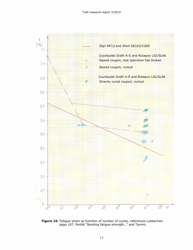
coupon thickness. These results are reported in ref. Perälä “Bending fatigue
strength…”. Both sets of results are converted from fatigue strength to fatigue
strain by dividing with the bending modulus 106 GN/m2 of ref. Tammi and present-
ed in Figure 10 together with the S-N curve of CFRP: Sigri NF12 and Shell
Figure 9. Shear modulus G of epoxy resins as function of temperature and post
curing, Ref. Korhonen “Composites as…” page 64.
Trafi research report 7/2015
17
GE163/C260 resin system of ref. Kensche “Fatigue of…”.
Figure 10. Fatigue strain as function of number of cycles, references Lukkarinen page 107, Perälä “Bending fatigue strength…” and Tammi.
Sigri NF12 and Shell GE163/C260
Sawed coupon, test specimen has broken
Sawed coupon, runout
Directly cured coupon, runout
Courtaulds Grafil A-S and Rütapox L02/SL66
Courtaulds Grafil A-S and Rütapox L02/SL66

Trafi research report 7/2015
18
GE163/C260.
The S-N curve of the sawed coupons (dashed black line, presented in ref. Tammi)
was used for the dimensioning of PIK-20D. It is seen in the figure that the curve
starts from the maximum static strain value and goes slightly below the Sigri NF12
and Shell GE163/C260 resin system curve (solid red line) at about 300 cycles. At
107 cycles the sawed coupon results are clearly above the solid red line.
The coupons cured under pressure directly to the final thickness (green symbols)
did not break (runout) at 107 cycles at any of the three test strains. As the results
were better than the sawed coupon results, used for dimensioning, there was an
extra margin and no change was needed in the design. At 107 cycles the PIK-20D
spar material sustains at least a strain of 0,667% whereas the corresponding value
for the Sigri NF12 and Shell GE163/C260 laminate is 0,400%. Assuming the same
slope for the coupons cured directly to the final thickness (solid black line) as for
the sawed coupons (dashed black line) the allowable number of cycles at the strain
ε=0,720 is about 50. In other words the PIK-20D spar material is noticeably better
than the curve used in Lukkarinen’s calculations. In conclusion L02/SL seems to be
a factor 10…100 (in life) better than the GE 162/163 resin family.
There is a difference in the cumulative damage sum in the case of PIK-20D with
Nyström’s elevated spectrum and measured strain between the calculations of ref.
Lumppio page 141 and Lukkarinen page L14-1. Control calculations showed that the
significant damage term was correct in the latter reference and consequently Luk-
karinen’s calculations were used as a basis for comparisons.
The S-N curve for the carbon fibre spar cap material properties, utilized by Luk-
karinen, is valid for a stress ratio of R=-1. This value is not true on the loading of a
wing but in reality the stress ratio varies maybe in a range of -0.55…-0.8. Conse-
quently using a stress ratio of R=-1 yields the most conservative results as quoted
in refs. Lukkarinen page 105 and Kensche “Fatigue of…” page 60.
Lukkarinen has applied a life factor of 4 in the calculations, ref. Lukkarinen page
108. When calculating the cumulative damage sum according to the Palmgren-Miner
rule
(1)
where ni is the number of load cycles and Ni the number of allowable load cycles at
a certain stress level, one should in theory use a value D=1.0 for the case when the
structure fails due to fatigue. FAA bases on this value their recommendation of a life
factor of 7 to 8 on metal structures with analysis alone, ref. AFS-120-73-2 page 7,
8. The lower value 7 may be used when “the designer presents data which shows
that his knowledge of the stresses and fatigue properties of his structure is compre-
hensive based on flight measurements and on previous test and use of the type
construction in similar designs”. The value of the cumulative fatigue sum D, corre-
sponding to a fatigue failure, varies both in metal and composite structures. Choos-
ing a value D=0,1 at fatigue failure, as is done in Lukkarinen’s calculations, is con-
servative by factor 5 when using a life factor of 4.
Lukkarinen’s fatigue life calculations contain conservatism due to two reasons. First-
ly he has used the 450 kg maximum weight (which includes water ballast) even in
the fatigue calculations of the aerobatic maneuvers. The second conservatism is due
to an error in deriving the spectrum from the Markov matrix. As explained on page
94 of ref. Lukkarinen the spectrum sequencies were derived counting the numbers
of load level exceedances, not physical load cycles. This has caused all load levels
below the maximum to also contain the number higher level loads in the cycles ex-
aggerating the numbers of load cycles by some tens of percent.
∑=
=k
i i
n
ND i
1

Trafi research report 7/2015
19
Using the (incorrectly derived) Kossira-Reinke load spectrum, with 12,5% aerobatic
flight added, the average S-N curve for a Shell GE 162/C260 resin system, with the
FEM method calculated peak stress, the stress ratio of R=-1, a life factor of 4 and a
cumulative fatigue sum of D=0.1 Lukkarinen has calculated for PIK-20D with a car-
bon fiber wing spar cap a fatigue life of (ref. Lukkarinen page 112):
PIK-20D 41838 FLH
The corresponding fatigue lives of PIK-20 and PIK-20B with glass fiber spar caps
and for PIK-20E with carbon fiber spar caps are (ref. Lukkarinen pages 110 and
114):
PIK-20 and PIK-20B 516000 FLH
PIK-20E 89535 FLH

Trafi research report 7/2015
20
4 Saab fatigue methodology
The Saab fatigue methodology on composite structures was based on the philoso-
phy of Barely Visible Impact Damage BVID, in which it is assumed that dropping
tools etc cause damage on the composite structure external surfaces. To take into
account such barely visible damage the composite structure was statically dimen-
sioned for a strain level that allows for a 6 mm hole anywhere in the structure. Con-
sequently such a low strain level also covers fatigue. However, it is not reasonable
to apply this philosophy on a sailplane wing spar or web that are inside the struc-
ture and thus protected from impact damage.
The Saab fatigue methodology (ref. Holm), used for metal structures of military and
civil aircraft, contains the following steps
- treatment of the loading spectrum
- normal correction of the coupon fatigue test
- application adjustment
- factors for life and stress
- choice of the cumulative damage sum D
In the first step the loading spectrum, based on the average use of the aircraft, is
modified so as to cover the limit fatigue loads that the aircraft will experience. This
means that the average loads are increased to cover the limit fatigue loads. Often
at Saab the loads have been increased by a factor of 1,5 in load cycles (at low
number of cycles) and by a factor if 1,15 in stress (at high number of cycles), ref.
Holm page 11/9.
In the second step of normal correction the coupon fatigue test results are correct-
ed to take into account the scatter between different material batches. In the Saab
methodology the average curve results are reduced to a level so as to cover all val-
ues above the lower quartile of the average values, ref. Holm page 11/22.
In the third step of application adjustment the Saab method takes into account dif-
ferences between the material coupon test data and the analyzed application case.
In metal structure following factors are of interest: stress concentration, size of the
test coupon (a small coupon has higher fatigue stress values in metallic materials)
and surface effects (such as surface roughness, surface treatment, heat treatment,
fretting and corrosion). In the application adjustment procedure for metal structures
the allowable stress amplitude σa is expressed as (ref. Holm page 11/24…32)
(2)
where index 1 refers to the material test values and 2 to the application adjusted
values. α is the stress concentration factor and Ψ a factor taking into account the
surface effects such as machining, surface treatment, surface hardening, fretting
and corrosion. The surface effect factor
(3)
where κm is a factor due to surface roughness (due to machining , lathing, polishing
etc) and κs due to surface treatment (such as an anodic oxidization or an alodine
process). δ is the volume factor
Ψ=2
112 )()(α
ασσ aa
sm κκδ ⋅⋅=Ψ

Trafi research report 7/2015
21
(4)
where V1 is the stressed volume in the material test coupon and V2 in the applica-
tion and m in the exponent is a material parameter. m=30 for steel. The stressed
volume may be expressed as
(5)
where ρ is the radius of the notch, λ is the material thickness at the notch and c a
constant.
The surface effect factor is assumed to have full effect at N=106 cycles and the val-
ue 1,0 at N=101 with linear interpolation on a log scale in between and constant
values beyond.
In the fourth step scatter reduction factors are applied on metal structure fatigue
curve to account for the uncertainty of the fatigue calculations and the scatter in
the fatigue tests within the tested material batch or full scale test. A factor is ap-
plied on the application adjusted fatigue curve of step three either in number of cy-
cles at low values of cycles (a life factor) or in stress level at high values of cycles.
In ref. Holm on page 11/33 are quoted the typical values 3 in life and 1,3 in stress
level. A factor of life of 3 implies a risk to fracture of about 0,001 and a factor of 4 a
risk to fracture of about 0,00001, ref. Jarfall page 97.
In the fifth step the limit value for the cumulative damage sum D is chosen, that
corresponds to the fracture of the structure. Jarfall (page 104) gives examples of
values on D corresponding to fracture in metal structures in a number of examples.
The example values range from 0,12 to 3,8. At Saab the following values have been
used in fatigue calculations of metal structure (ref. Holm page 11/35)
D = 0.5 in structures loaded with stress ratio R=-1
D = 0.7 in structures with other loading ratios
D = 1.0 for lugs with other loading ratios
It is also stated in the Saab fatigue methodology (ref. Holm page 11/22) that “su-
perposition of all individual effects in fatigue must be made with careful considera-
tion so that the overall effect becomes realistic and well balanced”. In other words
making conservative assumptions on several effects does not give a realistic but a
very conservative assessment.
m
V
V/1
2
1
=δ
cV ⋅⋅= λρ 2

Trafi research report 7/2015
22
5 Wing spar cap fatigue
A critical review of PIK-20D wing spar cap fatigue calculations is made by compar-
ing them step by step with the Saab fatigue methodology.
The first step is the treatment of the loading spectrum. The Kossira-Reinke load
spectrum contains the treatment of limit fatigue loads as the measured flight loads
have been extrapolated to contain the maximum loads during the aircraft life time.
However, the extrapolation has been performed, not to the 6000 FLH life time tar-
get, but conservatively to 6000 FLH times life factor 3 generally used in glider fa-
tigue tests in Germany (ref. Kossira & Reinke page 46). Besides a normal life factor
conservatism has been used in the extrapolation also yielding in a double effect.
However, the effect of the extrapolation is not large. Hence the spectrum is treated
principally in the same way as in the Saab method. However, Lukkarinen has used
an incorrect procedure when deriving the load spectrum from the Markov matrix. He
explains on page 94 of ref. Lukkarinen, that load level exceedances are collected in-
to the spectrum instead of physical load cycles. In this manner the spectrum used
by Lukkarinen has contained successively too many cycles at lower load levels. The
number of load cycles has been some tens of percent too high. A corrected spec-
trum was derived by mirroring the upper Markov matrix triangle and counting the
average number of physical cycles. Values of every element on row were summed
up in the same way as in ref. Lukkarinen. This means that instead of performing a
rainflow count of each physical load cycle, with an average and amplitude load, all
cycles on a row are conservatively treated as having a stress ratio R=-1. This spec-
trum was used in the fatigue calculations of Appendices 1 to 3.
In the second step a normal correction of the coupon fatigue tests should be per-
formed by reducing the average values to lower quartile values. Apparently this re-
duction is not available for the material tests utilized in the PIK-20 calculations. On
the other hand the material fatigue curve is not for the fiber and resin combination
used in PIK-20 production, but another composite combination with lower fatigue
properties. Comparisons on the two resin system fatigue properties, based on LBA
material acceptance tests and torsion tube fatigue tests, show that the resin used in
PIK-20 has a factor 10…100 in life better fatigue properties, than the material prop-
erties used for the fatigue calculations. Fatigue tests on PIK-20D actual spar cap
material showed a factor 50 improvement. A feel for the effect of the reduction from
average to lower quartile values in composite materials is obtained in ref. Kensche
“Lifetime of…” in fig. 8 on page 53. It is seen in the figure, that in a glass fiber
epoxy girder the reduction from average to 95% survivability at 95% confidence
level is about a factor of 10 in life. Material A –values are defined as values ensuring
99% probability with 95% confidence and they deviate from the average values
about three standard deviations (3σ). The lower quartile could conservatively be
around 2σ. So the lower quartile could be around a factor 7 lower than the average
values. Consequently the PIK-20 calculations contain a conservative approximation
of about factor 7 in life for the adaptation of the coupon fatigue tests.
However, the fatigue calculations will be completely revised with the actual S-N
curve for the PIK-20D spar cap material, Courtaulds Grafil A-S carbon fiber and
Rütapox L02 resin system cured under pressure directly to the final thickness, see
Figure 10.
In the third step application adjustments are made, which means adjustments due
to differences of the actual analyzed component from the fatigue coupon tests. Rel-
evant factors here are stress concentration, test coupon size and stress ratio.
Stress concentration arises usually in a notch and the test coupon has to be formed
to preferably have the same notch, otherwise a comparative calculation needs to be

Trafi research report 7/2015
23
made to account for the variation between the notch in the analyzed component
and the test coupon. In the case of PIK-20 wing spar there is no notch but there is
a (mild) stress concentration due to the abrupt stiffness and a geometry change in
the structure. As the maximum stress is used in the fatigue calculations the effect
of stress concentration is appropriately handled in the calculations.
The size of the test coupon has an effect on the fatigue properties. In composite
coupons the effect is reversed to that of metal coupons. It is known that in compo-
site structures coupon tests yield conservative results compared with component
tests such as a wing, ref. Waibel page 59. Consequently the PIK-20 fatigue calcula-
tions are conservative in this respect.
As noted in chapter 3 the handling of the stress ratio is conservative in the calcula-
tions. Further discussion on this issue follows in connection with the cumulative fa-
tigue sum.
In the fourth step factors in life or stress are applied to account for the uncertainty
of fatigue calculations. In PIK-20 calculations Lukkarinen has applied a factor of 4 in
life. This corresponds to a probability of fracture of the structure of about 1*10-5,
which is used for commercial aircraft. Further discussion on this issue follows in
connection with the cumulative fatigue sum.
In the fifth step the limit value for the cumulative fatigue sum D is chosen, that cor-
responds to the fracture of the structure. There is a fairly large variation of the limit
value D, that brings the calculations to match the test results. Kensche “Method
of…” quotes on page 47 that the value of D can vary from 0,1 to 10 for metals as
well as for composites. For metallic wing structures the Saab fatigue calculation
method uses a limit value of D=0.7 corresponding the fracture of the structure as
mentioned in chapter 4. Compared with these numbers the tentative suggestion by
ref. Kensche “Fatigue of…” page 60 of using D=0,1 together with a life factor of 3
feels quite conservative. Compared with D=0.7 it would introduce a supplementary
life factor of 7. However, Lukkarinen has conservatively utilized a cumulative fatigue
sum value D=0,1 together with a life factor of 4.
The Saab fatigue method emphasizes that “all individual effects in fatigue must be
made with careful consideration so that the overall effect becomes realistic and well
balanced”. The method aims at a calculation that dimensions the structure in a, not
too optimistic or pessimistic, but realistic way to fulfill the specified fatigue life with
the chosen probability to fracture. Main structural components, such as a wing, are
then fatigue tested to demonstrate the fatigue life if the airworthiness requirements
specify this. In the past a fatigue test has been required for military and large
commercial aircraft (CS-25) but not for simple structures with past experience on
small civil aircraft (FAR 23). The Saab method was originally developed for military
aircraft, which is reflected in the probability to fracture of 0,001 and the associated
life factor 3.
The factors in PIK-20 fatigue analysis that stick out from a well balanced overall ef-
fect are
- the Sigri NF 12 and GE 162/C260 laminate S-N curve
- stress ratio R=-1
- a life factor of 4
- a cumulative fatigue sum D=0.1
The usage of Sigri NF12 and Shell GE163/C260 laminate S-N curve instead of Cour-
taulds Grafil A-S and Rütapox L02/SL laminate curve is about factor 50 (in life) con-
servative. This conservatism is eliminated by using the appropriate S-N curve for
the PIK-20 spar cap material as shown in Figure 10.
The usage of stress ratio R=-1 data is conservative according to Lukkarinen and

Trafi research report 7/2015
24
Kensche, but no quantification is quoted how much. Accept this conservatism here
and use the maximum strain as the amplitude strain with a zero constant strain.
The fatigue calculation is based on the corrected Kossira-Reinke spectrum with
12,5% aerobatic flight added. The fatigue calculation is made with the 450 kg take-
off weight, which is conservative, because aerobatics is flown without water ballast
at maximum 360 kg take-off weight. These conservative approximations are ac-
cepted here.
The life factor 4 corresponds to a probability to fracture of 1*10-5, which is appropri-
ate or maybe conservative for a sailplane as the lower probability has been applica-
ble for commercial aircraft. However, an appropriate value for the life factor would
be 8 according to FAA’s practice when analysis alone is performed.
The life factor of 8 shall be used together with a cumulative fatigue sum D=1,0 on
metal structures. Even if the cumulative fatigue sum, that fits best the failure of the
structure, may be somewhat lower, FAA in a practical way puts all margins to a sin-
gle factor. Following the same principle for composite structures one would use a
life factor of 8 together with a cumulative fatigue sum of D=1,0.
The Saab fatigue method on the other hand uses the most likely cumulative fatigue
sum value D, matching the structural failure, together with the life factors appropri-
ate for testing as the fatigue of the structure would be verified in a component or
full scale test.
Here the following approach is chosen. A cumulative fatigue sum value D, matching
the structural failure, is used together with a life factor appropriate for calculation.
Lacking better data the value D=0,1 is used together with a life factor of 8. This ap-
proach is more conservative than FAA’s.
The revised fatigue calculation, performed in Appendix 1, yields the following fa-
tigue life for the spar cap of PIK-20D
PIK-20D 4,829*1020 FLH
based on the correct Kossira-Reinke load spectrum, with 12,5% aerobatic flight
added, the reduced S-N curve of Courtaulds Grafil A-S carbon fiber and Rütapox
L02/SL66 resin system, with the FEM method calculated peak stress, the stress ra-
tio of R=-1, a life factor of 8 and a cumulative fatigue sum of D=0,1. Only the high-
est load level at n=6,62 contributes to fatigue. This is the most likely outcome of
the fatigue life, but still conservative due to the conservative choice of the limit val-
ue D, the approximation in the stress ratio R and the handling of the aerobatic flight
spectrum.

Trafi research report 7/2015
25
6 Wing spar web fatigue
Kensche has also studied the fatigue of shear webs. His fatigue tests with torsion
tubes and KoSMOS spectrum yield a fatigue life of 450000 FLH at stress levels typi-
cal for a sailplane wing shear web, ref. Kensche “Lifetime of…” page 54. This fatigue
life is less than the quoted 123*106 FLH for a spar cap at a design strain level
0,61%, common for sailplanes, ref. Kensche “Lifetime of…” page 53. This indicates
that a spar web might be more critical than a spar cap. Kensche however points out
that the presented results are valid for plain fabric and GE162/C260 resin system.
Kensche correctly notes that “in spar webs the strain is composed of shear loads
and spar flange elongation induced by the bending moment”, ref. Kensche “Proposal
for…” page 33.
The wing spar web on PIK-20D is made of Interglas 92125 glass fiber cloth and Ru-
tapox L02+SL resin with the fibers in +45o/-45o to the spar axis. In the stress cal-
culations of the web the combined stresses due to the shear and bending stresses
have been determined and appropriately taken into account by reducing the allowa-
ble shear stress in the presence of the normal stress, see ref. Korhonen “PIK-20D
Calculations”, flap F Dimensioning of the web, page 1 and 5. In the past allowable
values for the normal and shear stresses were used in dimensioning. At present di-
mensioning is normally based on maximum allowable strain in fiber direction.
At the neutral axis, where pure shear prevails, the allowable shear stress at limit
load for a +45o/-45o glass fiber laminate was τyz= 54 MPa, ref. “Summary of the
most severe …” page 2. The corresponding allowable shear strain can be derived as
(6)
= 54/9400
= 0,00574 = 0,574%
The pure shear stress τ is equivalent to a state of acting stresses in the fiber direc-
tions
which can be derived from force balance on a triangle element. The maximum strain
in this biaxial stress state can be derived as
(7)
where the first term is the strain due to the stress in the principal direction and
the second term is the contraction due to the stress in the perpendicular direc-
tion. and are the moduli of elasticity in fiber direction for a +45o/-45o lami-
nate (which is the same as the modulus of elasticity in fiber direction for a 0o/90o
laminate) and is the Poisson number indicating contraction in direction 1 due to
a stress acting in the perpendicular direction 2. The expression can be developed to
a form
2
212
1
1
EE
σν
σε −=
G
yz
yz
τγ =
τσ =1
τσ −=2
1σ
2σ1E 2E
12ν

Trafi research report 7/2015
26
(8)
where is the modulus of elasticity for a 0o/90o cross ply weave in fiber direc-
tion (which is the same as for a +45o/-45o laminate in fiber direction). is the
Poisson number indicating contraction in 0o direction due to a stress acting in the
perpendicular 90o direction. Using the material values of ref. “Summary of the most
severe …” page 1 the allowable shear stress τyz= 54 MPa corresponds to an allowa-
ble maximum strain in fiber direction
= 0,00352 = 0,352%
However, the maximum allowable strain in 0o direction for a 0o/90o glass fiber lami-
nate, based on fatigue, is
εall = 0,8% ref. “Summary of the most severe …” page 1
which shows that the allowable shear stress, used in the past, is quite conservative.
The exact origin of the allowable shear stress is not known anymore as shear fa-
tigue test reports have not been found.
However, there are fatigue tests on glass fiber laminate made with tension test
specimen. The S-N curve in Figure 11 for a 0o/90o symmetric glass fiber laminate
with Interglas 92145 cloth and Rutapox L02/SL resin system offers more insight on
the fatigue properties of glass fiber laminate. It is seen in the figure that, adding a
tentative straight line for a reduction from average to lower quartile fatigue values,
a maximum strain of 0,8% corresponds to a number of cycles of roughly 106, which
is very conservative.
The measured shear strains in the PIK-20D wing spar web are shown in Figure 12.
It is seen in the figure that at limit load the shear strains are generally modest, be-
low γγγγyz = 0,5%, which corresponds to a maximum strain in fiber direction of
0,307%. This is true everywhere except at a station y = 34 mm from the root rib
reference station. At this station the shear strains at the web neutral axis at limit
load n=6,62 are
γyz = 0,964% forward side
γyz = 0,622% aft side
Using equation (6) these values correspond at limit load n=6,62 to a shear stress of
τyz= 90,6 MPa forward side
τyz= 58,5 MPa aft side
respectively, which exceed the allowable shear stress of τyz= 54 MPa, ref.
“Summary of the most severe …” page 2.
One can think of different reasons for the high strains. The strain gage number 1
could be defect causing incorrect values. This does not seem to be the case as the
measurements in another load case in Appendix 16b of ref. Nyström at
90/0
90/0
90/0 EE
τν
τε
−−=
20100
54)31,01(max +=ε
90/0
90/0 )1(E
τνε +=
90/0E
90/0ν

Trafi research report 7/2015
27
n=-(4,62+20%) seem to be in line with the results of Figure 12. The acting shear
force in the wing spar web is caused by the wing lift (normal force) integrated from
the wing tip to the section in question, which means a gradual increase towards the
root. As the web height increases due to the wing taper, the shear flow is fairly con-
stant and does not explain the high shear stresses at the root. The directional
change of the wing spar caps in the vicinity of the root rib could cause changes in
the web shear stress, but one would expect about the same effect on the forward
and aft faces of the sandwich web skins only 10 mm apart. The web shear force is
reacted in the root rib structure in the fuselage shear pins, but also closest to the
web in the root rib bush, where the reaction from the other wing spar end is taken
up. This asymmetric reaction could explain the asymmetry in the wing web forward
and aft shear strains. On the left wing root the right wing spar end fitting pin is lo-
cated aft of the right wing spar and the maximum strains would be expected there.
Nyström quotes on page 69 in ref. Nyström, that “especially the shear strains were
unexpectedly high in the vicinity of the root rib, but they were not critical for the
type design wing that was in production”. An interview 6.2.2015 with the production
manager of PIK-20D, Mr Markku Hiedanpää, confirmed the case. He testified that a
third 92125 glass fiber cloth was added to the PIK-20D type design configuration on
each side of the web root area at y=0 to 250 mm after the fabrication of the fatigue
test wing. This is shown by a different pencil line in the drawing 1-20D-54-200a.
Figure 11. S-N curve of 0o/90o symmetric glass fiber laminate with Interglas 92145
cloth and Rutapox L02+SL resin system. The test was performed using a
tension test coupon. The stress ratio R=0,15 and εmax is the maximum
strain in the cycle in the coupon 0odirection, ref. Perälä “Theoretical and
experimental determination…”, Appendix 3, page 1.
Test specimen has broken
Runout, no failure in test

Trafi research report 7/2015
28
Fig
ure 1
2.
PIK
-20D
win
g s
par
web s
hear
str
ain
s γ
yz a
t lim
it load n
=6,6
2.
Rig
ht
win
g,
vie
w lookin
g a
ft. The n
um
bers
in t
he
circle
s identify
:
to
p
– d
ista
nce y
fro
m r
oot
rib r
efe
rence s
tation
m
iddle
– s
train
gage n
um
ber
bott
om
– n
um
ber
of
sta
tic t
est
The d
ashed lin
e indic
ate
s t
hat
the s
train
gage is o
n t
he a
ft s
ide o
f th
e w
eb.
Ref.
Nystr
öm
, Appendix
13a,
16a.

Trafi research report 7/2015
29
At the station y=34 mm from the root rib reference station there were thus two
glass fiber weaves of 92125 in +45o/-45o direction in the static test. The bonding of
the web to the root rib was unchanged with four weaves of 92125 in +45o/-45o di-
rection, ref. drawing 1-20D-54-200a. Due to tapering in the layup only three of
these weaves covered the strain gage station y=34 mm. In the static test there
were in total five weaves of 92125 which were increased to six in the type design
configuration.
Using equation
(8) the strains in the fiber directions at the strain gage station y=34 become at limit
load n=6,62
forward side
aft side
The highest strain on the web forward side is reduced by the increase of the weaves
from five to six to
for the type design configuration. This is the limit load strain that can be compared
with the reduced S-N curve of Figure 11.
In the wing spar web the stress state is such that in the principal direction the
strain is ε and in the perpendicular direction the strain is -ε. The S-N curve is valid
for a biaxial stress state, in which the principal strain is ε and in the perpendicular
direction the strain is -νε. Thus the stress states are not exactly equal, but in the
principal direction the strains are the same. Another difference between the wing
spar web and the fatigue test is in the weaves. The wing spar web was made of In-
terglas 92125 weave with 50% of the fibers in the principal direction and 50% in
the perpendicular direction. The fatigue test coupon was made of Interglas 92145
with 90% of the fibers in the principal direction and 10% in the perpendicular direc-
tion. In a 0o/90o layup the amount of fibers is however the same in both directions.
The stress ratio of R=0.15 implies that the maximum load is 6,67 times higher than
the minimum load. This simulates quite well the wing maximum load cycles due to
gust loads and maneuvering loads. A shortcoming in the test is that it only covers
the tension loads in the principal direction.
Using the corrected Kossira-Reinke spectrum with added 750 FLH of aerobatic flight,
the cumulative damage in the web can be calculated. The calculation is performed
in Appendix 2. Using a limit value D=0,1 for failure and a life factor of 8 the calcu-
lated life for the most critical point in the wing spar web is
938156 FLH
It can be seen in the table of Appendix 2 that the largest contributions to the fa-
tigue emerge from low load levels at n=1,1…1,47 where aerobatic flight is not a fac-
tor. The estimate is very conservative as the S-N curve used is more severe than a
lower quartile curve and the log-linear extrapolation to very high number of cycles
where the log-linear line unphysically crosses the zero strain level. There is no indi-
cation of a fatigue problem in the wing spar web.
%590,000590,020100
6,90)31,01( ==+=ε
%381,000381,020100
5,58)31,01( ==+=ε
%492,000590,06
5==ε

Trafi research report 7/2015
30
7 Wing fatigue test
The fatigue test on PIK-20D wing was performed using the Nyström spectrum with
44% elevated strain levels, a 4000 FLH spectrum length and applying a scatter fac-
tor of 4 on life, ref. Nyström page 43. The elevated strain level offered a possibility
to change the structure in the future and save weight. However, this was never
done as it would have required changes in the existing spar cap tooling, web height
etc.
Nyström quotes that FAA recommends in ref. AFS-120-73-2 that loads at limit load
level and loads with 10 cycles or less should be omitted. The author of the present
paper recalls that Saab’s practice was to leave out from the fatigue sequence loads
exceeding 85% of limit load also on aircraft with composite structure. The intention
of omitting high loads is the fact that high loads may cause yield in metal parts
which is non-conservative for the fatigue testing of those. Also rare high loads are
uncertain and may cause damage in composite parts in a way not representative of
the aircraft usage.
FAA says in ref. AFS-120-73-2 that “the test loads are to extend to the lowest level
that causes significant damage unless such loads are otherwise accounted for”. The
Nyström spectrum is not truncated but contains all theoretically derived load levels.
Nyström’s spectrum fulfills the FAA guidance in the reference above on load levels,
sequence block size and order etc.
In Nyström’s original spectrum the maximum load level was n=5,0 being 76% of
the limit load n=6,62 (ref. Nyström page 42). At the 44% increased load level the
load factor would have been increased to n=7,2. When the test load level was in-
creased by 44% these cycles (10 cycles in 4000 FLH) were left out of the sequence
as they were moved to the static tests for deflection measurements etc, ref. Nys-
tröm page 43…45. The highest load level remaining in the sequence comprised of
40 cycles in 4000 FLH and was elevated 44% from n=4,33 to n=6,24. This load
level is 94% of the original limit load factor n=6,62 at the maximum take-off mass
450 kg. The test sequence can consequently be considered quite tough.
The fatigue test wing was exposed to extra loadings due to mishaps in the testing.
During the fatigue test the wing experienced three breaks in electricity or control
signal distribution. No damage was observed on the wing but the level of excessive
loading remains unknown, ref. Nyström page 61. During the first static test trial to
n=6,62+20%, before the fatigue test, the wing came instantaneously down from
n=6,62+15% to zero level due to a built-in safety limit. In this incident the wing
shell was fractured about 2,5 m from the wing tip where the spar cap ends and the
load passes over to a unidirectional carbon fiber tape on the wing skin, ref. Nyström
page 65. The wing was repaired according to the repair manual before further test-
ing, ref. Perälä “Static and other tests…” page 2. After the first static test to n=6,62
+ 20% a fracture was noticed at the end of the spar at the spar end main fitting in
the bonding between the spar cap and the web. This damage was probably also
caused in the previous mishap. A repair was made by injecting resin into the struc-
ture.
At this stage the strain peak in the spar caps at the root rib was noticed in the
strain gage recordings. The unreinforced wing was according to PIK-20D type de-
sign with the spar caps fabricated according to drawing number 1-20D-54-200a, but
with the exception that the spar web did not have the third glass fiber weaves
Interglas 92125 in the root area at y = 0 to 250 mm from the root rib station. To
create a more even strain distribution in the wing spar it was decided to locally rein-
force the upper spar cap and the web forward side in the vicinity of the wing root
rib and a repair was made, ref. Perälä “Static and other tests…” page 4…7.

Trafi research report 7/2015
31
After the fatigue test a static test was performed to n=9.53 at room temperature
and the wing was broken at elevated temperature with maximum temperature at
71oC at n=7…8, ref. Perälä “Static and other tests…” page 12…14.
Wing spar cap
Before reinforcing the wing root area there were about 30 static loadings performed
for calibration, strain measurements and deflection purposes, ref. Nyström page 79.
The strain measurements give useful comparison for FEM calculations as the inter-
nal stress distribution is appropriate in the test. It can be identified, that for the un-
reinforced wing a load case with load factor n=6,62+20%=7,944 was applied 9
times and the case with n=6.62+15% once (ref. Nyström pages 64…66, Appendices
12, 15a1…h2). The applied static load cases are summarized in Table 2. The wing
spar cap maximum strain is the peak value predicted by the FEM calculation, see
Figure 8.
The cumulative damage sum for these 10 cases can be calculated using the
Palmgren-Miner expression (1). Using the same S-N curve as in the Appendix 1 the
fatigue calculation of the 10 static cases yields a cumulative fatigue sum of
8,324*10-9 which is a factor 5,357.1010 higher than with the entire Kossira-Reinke
spectrum with 12,5% aerobatics added. This is consistent with the comment of
“composites are extremely sensitive to variation in the number of high loads in the
fatigue spectrum” ref. Tomblin & Seneviratne page 34. The static tests on the unre-
inforced wing spar were thus much more severe than the entire fatigue test. Con-
sidering the static test as the critical part of the Kossira-Reinke spectrum they cover
a life of 9*6000/(10)*5,357.1010=2,893.1014 FLH.
After reinforcing the wing the following static test confirmed that the maximum
compression spar cap strain in the fatigue test wing (gage 71) was reduced by
20,79%, ref. Perälä “Static and other tests…” page 10. With that reduction the spar
cap maximum strain obtains in the static tests the values shown in Table 2. The
static tests on the reinforced wing are not significant in fatigue.
In the fatigue test the loading was increased by 44%, but due to the spar cap rein-
forcement the maximum strain level was reduced by 20,79%. The strain level was
increased by 19,2 % compared with the original Nyström spectrum. As the maxi-
mum load level in the elevated Nysröm sequence is n=6,24 yielding a strain of
ε=0,40266% on the reinforced wing the fatigue test in total is less severe than the
Kossira-Reinke spectrum including 12,5% aerobatics performed on the type design
wing.
The static tests on the unreinforced wing, however, represent a severe fatigue test.
The strain measurements give useful comparison for FEM calculations as the inter-
nal stress distribution is appropriate in the test. Increasing the load level in aircraft
fatigue tests is an acknowledged way to reduce the time needed to perform the
Table 2. Overview of static load cases applied on the fatigue test wing.
Wing spar cap maximum strain
[%]
Load level Load factor Unreinforced
wing
Reinforced wing
Limit load 6,620 0,53930 0,42718
Limit load + 15% 7,613 0,62020
Limit load + 20% 7,944 0,64716 0,51262

Trafi research report 7/2015
32
testing and to increase the statistical confidence, see ref. Tomblin & Seneviratne.
Compared with theoretical analysis the test introduces the loads in an appropriate
way and creates a correct internal loads distribution. Low loads are enhanced to a
higher level thus permitting a reduction of the number of corresponding cycles.
Thus a considerable reduction is obtained in the testing time. High loads cannot be
enhanced to even higher levels as they would impair the results when metal com-
ponents are exposed to yielding (plasticity). Sequences with high loads are on the
contrary increased in number to increase the statistical confidence of the test. Due
to the low number of cycles of the high loads the effect on the total time for testing
is however negligible. The reference above presents a survey on the effects of the
load enhancement factor and the life factor. Figure 13 shows the load enhancement
factor as function of the test duration for a constant statistical confidence based on
three databases (NAVY, NIAR and CASA) on composites fatigue data variability as
well as some material combinations.
The load enhancement factor can be applied to the fatigue spectrum in several
ways:
- to 1-g mean fatigue load
- to amplitude
- to minimum/maximum load
When the stress ratio R is negative (cycles with load reversal) it is important to
maintain the same stress ratios throughout the spectrum, ref. Tomblin & Senevirat-
ne page 35. In other words the third alternative is recommended and this is the
way the loads were increased in the PIK20D fatigue test.
individual test series.
Figure 13. Influence of test duration on B-basis Load Enhancement Factors (LEF) for different materials data bases, ref. Tomblin & Seneviratne page 80.

Trafi research report 7/2015
33
To get a feel for the effect of increasing the loads by 20% use the average gradient
of the data base curves to find out how large change this corresponds to in testing
time (only the slope of the curve is relevant here). Use the gradient of the Navy da-
ta base as it has the largest scatter in fatigue of the data bases (ref. Tomblin &
Seneviratne page 23 and 80) as wet layup tends to have a higher scatter than pre-
preg production. It is easily derived from the data that a load enhancement factor
1,2 corresponds about to a factor 14 in testing time based on equal statistical confi-
dence. This would mean that the performed static tests at the 20% elevated strain
level are equivalent to 5400*14=75600 FLH on the wing spar cap with a life factor
of 1 in excess of the elevated Nyström spectrum. Applying a life factor of 4 the stat-
ic tests cover a life of 18900 FLH in excess of the fatigue test itself. The obtained
estimates on fatigue life, based on Kossira-Reinke spectrum with 12,5% aerobatic
flight added, can now be summarized
18900 FLH based on static tests at elevated strain level and a conversion
with equal statistical confidence
2,893.1014 FLH based on static tests at elevated strain level and a conversion
calculated with cumulative damage sums on the two spectra
4,826*1020 FLH based on cumulative damage sum calculation
The different estimations on PIK-20D fatigue life give all fairly high values. An ex-
planation for the long fatigue life is that the chosen dimensioning strain levels on
PIK-20D are fairly low. In the carbon fiber spar caps the intended maximum strain
at limit load was 0,5% in fiber direction, ref. “Summary of the most severe …” page
1. The actual strain at limit load in the strain peak in the spar cap just outboard of
the root rib is 0,5393%. This is over 10% lower than the value 0,61%, quoted on
page 53 of ref. Kensche “Lifetime of…” and ref. Waibel page 58 as a common de-
sign level (limit strain) of a sailplane spar. The fatigue tests of the PIK-20D spar cap
material, cured under pressure, showed that the material can sustain at least a
strain of 0,677% for 10 million cycles.
Wing spar web
On the unreinforced wing web forward side the maximum strain at the root in fiber
direction was at limit load ε=0,590% as shown in the previous chapter. The strain
levels are so low that the static tests beyond limit load are not significant in fatigue.
The forward side of the wing spar web root area was reinforced at y=0 to 250 mm
with 3 weaves of 92125 so that the strain in fiber direction at limit load n=6,62 was
reduced from ε=0,590% to 0,354% in the test. Consequently the strain levels are
so low that the static tests on the reinforced wing are not significant in fatigue.
In the fatigue test the 44% elevated Nyström spectrum increased the strain in fiber
direction at limit load from ε=0,354% to 0,5098%, which exceeds the correspond-
ing value ε=0,492% for the type design configuration. The fatigue test was con-
servative on the web for the Nyström spectrum, which is though less severe than
the Kossira-Reinke spectrum with 12,5% aerobatics added.

Trafi research report 7/2015
34
8 Metal brackets fatigue
8.1 Wing spar end main fitting
The wing spar end main fitting is an AISI 4130 steel construction, quenched and
tempered to a Tensile Ultimate Strength of TUS=100 kp/mm2 (142,2 ksi), ref.
Korhonen “PIK-20D Calculation”, flap F Wing dimensioning, 3 Dimensioning of spar
root, bundle E Spar end and fitting attachment page 3. There is a lathed pin welded
to the fitting plate which is bolted to the composite spar end, see Figure 14 and ref.
Soinne page 19. The critical section in bending is inside of the pin 3,5 mm flange at
the junction of the 22 mm cylindrical part and the beginning of the 1 mm radius.
The welding of the pin flange to the fitting may somewhat reduce the bending mo-
ment at the cylindrical part, but this has been conservatively ignored. In aerobatic
flight (m=360 kg, n=6,62) the maximum bending stress amplitude in this section is
σa=39,7 ksi , ref. Appendix 3 page 71.
The stress concentration factor in the section at the fillet radius can be estimated as
α=1,717 bar ref. Peterson fig. 74, 75
α=1,63 shaft ref. Boeing Design Manual fig. 13.4.3-4
of which the former is conservatively used.
The material S-N curves are derived for a stress concentration factor α=2,0, a value
closest to the actual value, in material data of MIL-HDBK-5J figures 2.3.1.2.8(c)
(4130 Sht Norm, KT=2,0, TUS=120 ksi) and 2.3.1.2.8(g) (4130 Sht Hard, KT=2,0,
TUS=180 ksi). These curves present the average values of the allowable maximum
stress for different mean stresses. The curves were first normal corrected (by engi-
neering judgment) to represent the lower quartile values. Then the curve presenta-
tions were transformed to show the allowable stress amplitude for different mean
Critical section
Figure 14. Wing spar end fitting.

Trafi research report 7/2015
35
stresses. The ratio of the mean stress and the stress amplitude at different numbers
of loading cycles N was calculated using the Kossira-Reinke spectrum including 12,5% of aerobatic flight, see ref. Lukkarinen page L18-1. Using these values S-N
curves, having a varying stress ratio for the mean stress and the stress amplitude,
representative for the Kossira-Reinke spectrum including 12,5% aerobatic flight,
were constructed for the 120 ksi and 180 ksi material data. The S-N curve for the
142,2 ksi material was interpolated from these two curves and is shown in Figure
15 as the Normal corrected curve.
The allowable stress amplitude for the application adjustment was calculated using formulas (2)) to (5) of the Saab method. The ratio of the stress concentration fac-
tors in the test data and the application is α1/α2=2,0/1,717=1,165.
The volume factor δ is calculated using the pin shoulder fillet 1 mm radius with a
quarter of the pin perimeter as an approximation for the width of the maximum
stress area. The corresponding test specimen dimensions are found in the MIL-HDBK-5J figures. The volume factor obtains a value of δ=1,068.
For a lathed surface with a roughness value Ra=3,2 a surface roughness factor of
κm=0,85 is valid for a steel with TUS=1000 N/mm2, ref. Holm page 11/28. There is
no surface treatment factor κs for cadmium plating, ref. Holm page 11/29. Conse-
quently for the surface effect factor a value Ψ=0,908 at N=106 is obtained. At
N=101 Ψ=1,0 with linear interpolation on log scale in between and constant values
beyond the limits. With these data the Application adjusted S-N curve can be calcu-
lated and is depicted in Figure 15.
A reduction of the application adjusted S-N curve is made to take into account scat-
ter. At low cycles a reduction factor of fN=8 is used in line with FAA’s recommenda-
tion, ref. AFS-120-73-2 page 8. FAA does not recommend any reduction in stress at
high number of cycles. However, to have a comparable reduction at high number of
cycles a factor fS=1,8 is applied, which is a severe reduction compared with the
common value of 1,3 for metal structures in the Saab method. The Scatter reduced
curve is presented in Figure 15.
The wing spar end fitting fatigue calculation is based on the 6000 FLH Kossira-
Reinke spectrum without aerobatic flight. Using a cumulative fatigue sum limit value
D=0,7 and a scatter factor of 8 in life and 1,8 in stress the calculation in Appendix 3
yields a fatigue life of 265655 FLH. When 12,5% aerobatic flight (750 FLH) is add-
ed, the fitting fatigue life is reduced to 67607 FLH. If only aerobatics is flown the fa-
tigue life is reduced to 10872 FLH. Because the critical section is inside of the
shoulder fillet and inside of the fitting metal sheet, bolted to the wing spar, it is not
possible to inspect. For this reason the wing spar main fitting is a safe life part and
must be replaced when one of the following is reached
- 10000 FLH aerobatic flight only
- 65000 FLH total flight time including max 8000 FLH aerobatics
- 265000 FLH without any aerobatics
If more than 12,5% of the flight time has been flown aerobatics, a separate analysis
shall be made how much the 65000 FLH limit must be reduced. The Kossira-Reinke
aerobatic spectrum is not intended for gliders flying only advanced aerobatics.
When rigging the glider the wing spar end fitting bracket pin is inserted into a slide
bearing fixed in the other wing root rib. The bearing distributes the pin load to the
rib and is not fatigue critical taking only compression loads.

Trafi research report 7/2015
36
Application adjusted
Normal corrected
Scatter reduced
fN=8
fs=1,8
AISI 4130 142,2 ksi
Figure 15. Wing spar end fitting S-N curves.

Trafi research report 7/2015
37
8.2 Wing bevel pins
Wing bevel pins transfer the shear loads from the wings to the fuselage and are
lathed AISI 4130 alloy steel parts, quenched and tempered to a Tensile Ultimate
Strength of TUS=90 kp/mm2 (128,0 ksi, LN 1.7214.5 ref. Korhonen “PIK-20D Cal-
culations”, flap E Material data, page 11, see Figure 16. The pins are bonded to the
wing root rib holes at the forward auxiliary and rear spars. The critical section in
bending is inside of the pin 2 mm flange at the junction of the 22 mm cylindrical
part and the beginning of the 1 mm radius, see ref. Soinne page 34.
This section is massive but the bored hole end is rather close. The question is what
section is effective in bending? It is often quoted in static dimensioning that a point
load is spreading out in an angle of 90o (45o half angle). There is motivation for this
statement based on analytical plate theory solutions. Figure 17 shows the stress
distributions of an infinite plate where a point load P is acting in the plane of the
plate normal to the boundary. At a distance b from the edge the peak normal stress
is
(9)
where h is the plate thickness. Assuming a constant stress over a width l it can be
written as
(10)
Setting the constant stress equal to the actual peak value the effective width and
half angle can be determined. It turns out that the half angle becomes a value 38o.
The same result is obtained at any distance from the point load. Another analytical
plate theory solution is shown in figure Figure 18 for a point load bending an infi-
nitely wide flange attached to a wall. The bending moment intensity m due to the
point load P has a peak value
bh
P637,0=σ
lh
P=σ
Figure 16. Wing bevel pin, ref. drawing 3-20D-54-301-9 (a).
Critical section

Trafi research report 7/2015
38
(11)
Assuming constant moment intensity over a unit width it can be written
(12)
where a is the moment arm of the point load. Setting the constant moment intensi-
ty equal to the actual peak value the effective width and half angle can again be de-
termined. It turns out that the half angle becomes a value 47o. It is seen that the
Pm ⋅= 465,0
h
Pam
⋅=
1
Figure 17. Stress distribution on an infinitely wide plate due to a point load P acting in the plane of the plate normal to the boundary, ref. Girkmann page 63.
Figure 18. Bending moment intensity distribution on an infinitely wide flange attached to a wall due to a point load P acting on the edge
ref. Girkmann page 189.

Trafi research report 7/2015
39
45o value for the half angle, where the point load is spread out, is a good engineer-
ing approximation.
Assuming that the effective section inner diameter due to the hole end increases at
a 45o angle, the inner diameter is at the critical section 4 mm. At limit load (m=450
kg, n=6,62) the maximum bending stress amplitude in this section is σa=6,7 ksi on
the left wing forward bevel pin.
Compared with the wing spar end main fitting pin reference case there are now
changes in the application adjustment in the Tensile Ultimate Strength and stress
concentration factor. The volume factor is unchanged as the dimensions are the
same. Also the surface roughness factor is unchanged due to the same surface
roughness as the knurling does not extend to the radius. The stress concentration
factor is determined in the same way as for the wing spar end main fitting pin. Due
to a thinner flange a value
α=1,602 ref. Peterson fig. 74, 75
is obtained. Compared with the wing spar end main fitting pin reference case:
ref now
TUS 100 90 [kp/mm2]
α 1,717 1,602
δ 1,068 1,068
κm 0,850 0,850
The application adjusted and scatter reduced curves of the wing spar main fitting
pin, presented in Figure 15, can now be scaled in amplitude to apply for the present
case by a factor
At the scatter reduced allowable stress amplitude becomes 13,2 ksi. The
acting maximum stress amplitude at n=6,62 is 6,7 ksi, which is considerably less
than the allowable stress amplitude including the severe scatter factor in stress of
fS=1,8. The acting stresses are clearly quite low. Even at the highest load cycle
there is no contribution to the cumulative damage sum and no risk for fatigue. Con-
servative fatigue dimensioning is good, because it is not possible to inspect the crit-
ical section without removing the bonded pin from the wing root rib.
The fatigue spectrum of the bevel pin is not necessarily the same as for the wing
spar end main fitting pin, because except the wing bending moment, also the wing
torsion has an effect on the shear force. The torsion moment spectrum does not
have to be the same as for the bending moment due to different flap deflections.
However this does not matter as even the highest load cycle contributes nothing to
the cumulative fatigue sum. For the same reason the assumption of the effective
section increasing in a 45o angle is not critical.
When rigging the glider the wing bevel pins, fixed on the wing root ribs, are insert-
ed into corresponding bushes fixed in the steel tubes at the fuselage main frames.
The bushes distribute the pin loads to main frames and are not fatigue critical tak-
ing only compression loads.
965,011602,1
717,1
100
90=⋅⋅⋅
810≥N

Trafi research report 7/2015
40
8.3 Tailplane fitting loads
Ref. OSTIV paragraph 3.4 requires following horizontal tail loads for static dimen-
sioning:
3.411 Balancing tail load
3.412 Maneuvering load
3.413 Gust loads
3.44 Unsymmetric loads
The balancing tail load at load factor n=1 together with the gust loads give physical
load cases, which are repetitive and have a fatigue spectrum. The balancing tail
loads in maneuvers at higher load factors represent the tail loads in aerobatic ma-
neuvers and these shall be covered in fatigue.
The maneuvering loads cases also contain a maximum elevator displacement to
maximum deflection. This is an extreme panic load case in a collision evasive ma-
neuver, not a basis for fatigue loads. The maneuvering load cases also contain at
design diving speed VD a one third of maximum elevator deflection. This is not ei-
ther an aerobatic maneuvering case as aerobatic maneuvers are not performed at
VD.
The unsymmetric load case is an extreme static load case.
A search for the maximum repetitive gust load case, at a reasonable flap deflection
and speed combination, gives the following maximum horizontal tail load due to a
gust:
V=240 km/h
δf=-12o
n=6,62 Pmax= Pbalanced+∆P = -84-1220 = -1304 N ref. Korhonen H., “PIK-20D Stress
calculations”,Flap C, page 9
The horizontal tail angle of attack and elevator deflection angle in the gust case
were calculated as
αt=-12.282o ref. Soinne page 40,41
δe=3,452o
yielding a horizontal tail pitching moment Mt close to zero. The maximum tail load
can then be distributed to the forward and aft fitting reactions. It turned out that
the maximum tail load in the maneuvering cases was less than half of the above
gust case and the tail loads in aerobatic maneuvers are thus insignificant in fatigue.
The original tailplane position with the tailplane apex coinciding with the fin tip rib apex was modified in 1977 so there is another different tailplane configuration on
PIK-20D -78. The tailplane was moved forward 120 mm to reduce the interference
drag of the horizontal and vertical tail junction. Also the tailplane forward fitting
bracket was moved 120 mm aft on the tailplane side and the aft bracket with the
same amount forward on the fin side. Thus the distance between the forward and
aft brackets was reduced from 360 mm to 240 mm. The modified tail configuration
gives the critical maximum and amplitude loads on the forward fitting
FForward=1243 N
Fa=1163 N
and the original tail configuration on the aft fitting pin

Trafi research report 7/2015
41
FAft=238 N
Fa=223 N
The fitting brackets are unchanged and shall be checked for the loads of both con-
figurations.

Trafi research report 7/2015
42
8.4 Tailplane forward fitting
The tailplane forward fitting bracket, shown in Figure 19, is a welded AISI 4130 al-
loy steel construction, normalized and annealed to a Tensile Ultimate Strength of
TUS=67 kp/mm2 (95,3 ksi), ref. Korhonen “PIK-20D Calculations”, flap E, Material
data page 11. A standard Hirschmann 8 mm rod end is screwed into the fitting
bracket to enable the connection to the fitting bracket on the fin side, see ref.
Soinne page 45, 65.
The rod end material was initially free-cutting steel 1.0715 (AISI 1213). In 1977
there was crash landing in Australia with a PIK-20B which ended up in a gully and
the horizontal tail forward fitting rod end was fractured. It was first suspected that
fatigue in the rod end was a contributing factor, but metallographic studies con-
firmed that this was not the case and the fracture was a result of the high crash loads. However, the factory decided to change the PIK-20D rod end material to a
stronger 1.7218 alloy steel (AISI 4130). Rod ends with both materials are in use.
Steel 1.0715 has a Tensile Ultimate Strength of TUS=520 MPa.
Later on the bigger rod end and tailplane fitting bracket of PIK-20E were also used
on PIK-20D. The rod end has the same 8 mm pin but the rod shank has the larger
M10 screw thread as the PIK-20E tailplane fitting bracket.
When the rod end shank is screwed into the fitting bracket cylindrical part they form
a turnbuckle type of joint, where the load transmitted through each thread is not
constant along the helix but shows a peak at both ends of the mating threads.
Compared with a bolt and nut type joint, where there is only one load peak, there
are two lower load peaks, see Figure 20. According to ref. Peterson page 254 fa-
tigue tests on the turnbuckle type joint have shown a fatigue strength more than
double that of the standard bolt and nut combination.
The stress concentration at the bottom of the thread is due to the thread tooth
bending but also due to the loads from the other threads bypassing the thread bot-
tom notch. The critical section in the bracket is at the thread bottom, where the last
Critical sections
Figure 19. Tailplane forward fitting bracket and rod end, ref. drawing
4-20D-58-100-1(a).
Amendment A1

Trafi research report 7/2015
43
thread of the rod end shank bends the bracket thread tooth. In the rod end the crit-
ical section is at the shank thread bottom, where the last thread of the bracket
bends the shank thread tooth. The bypassing loads are fully developed at these sec-
tions as the rod end shank (G1) is shorter than the thread in the bracket. The stress
concentration in a threaded joint is not easy to estimate accurately as there is a
fairly large variation in reported values. Following values are quoted in the literature
α=2,7 Whitworth thread, bolt and standard nut, 3D photoelastic
tests by Hetenyi, ref. Peterson page 253
α=6,7 bolt and standard nut, 3D photoelastic tests with a larger
model by Brown and Hickson, ref. Peterson page 254
α=2…3 ISO metric thread, ref. Jindal page 264
The Whitworth thread has a has a root radius of 0,1373 pitch whereas the value for
ISO M8 male thread is 0,1248 pitch and for female thread 0,0624 pitch. The thread
forms are also somewhat different with a 27,5o slope in the Whitworth thread profile
and 30o in the ISO metric profile. Ref. Peterson recommends that the value 6,7
should be used in design where fatigue (or embrittling) is involved with a correction
factor for notch sensitivity.
According to ref. Peterson it is well known that the effect of a notch on the fatigue
strength of part varies considerably with material and notch geometry and is usually
less than the effect that would be predicted by use of the geometrical stress con-
centration factor α, which is a theoretical factor. For scratches, tiny holes and radii
approaching zero the strength reduction does not follow the geometric stress con-
centration factor and is in steels of low tensile strength often quite small. Notch
sensitivity q is defined
(13)
where Kf is the acting fatigue notch factor and α is the geometrical stress concen-
tration factor. Notch sensitivity factor may be considered as a measure of the de-
gree to which the theoretical effect is obtained. Reasonable values for design use
are obtained in Figure 21, where the following simple formula has been used
(14)
1
1
−
−=
α
fKq
ρa
q+
=1
1
Figure 20. Stress concentrations in bolt and nut and bolt and turnbuckle type joints.

Trafi research report 7/2015
44
where ρ is the notch radius in inches and a is a material constant with values given
for steels, based on tensile ultimate strength, on page 11 of ref. Peterson. Due to
different dimensions and materials with a different effect on notch sensitivity it is not possible to say which part is more critical and both the forward fitting bracket
and the rod end need to be studied in fatigue.
Fitting bracket. At the fitting bracket thread bottom net section with the spectrum
maximum amplitude loading of 1163 N, occurring on the modified tail configuration,
the maximum acting stress amplitude, taking conservatively into account the turn-
buckle type fitting load peak with a factor ½, is σa=3,0 ksi.
Compared with the wing spar end main fitting pin reference case there are now
changes in the application adjustment in the Tensile Ultimate Strength, stress con-
centration factor, volume factor and the surface roughness factor.
The stress concentration factor α=6,7 is used for the geometric stress concentration
value. For the steel with TUS=67 kp/mm2 = 95,3 ksi a parameter value a=0,00756
is interpolated using ref. Peterson page 11 values. Using formula (14) a notch sen-sitivity value q=0,289 is obtained. Equation (13) gives a fatigue notch factor
Kf=2,647.
The volume factor δ is calculated using the thread bottom radius 0,078 mm with a
quarter of the perimeter as a conservative approximation for the width of the max-
imum stress area. The corresponding values for the material test coupon are found
in the MIL-HDBK-5J figure. The volume factor obtains a value of δ=1,309 at N=106
as the stress peak in the application has a considerably smaller volume than in the
material test coupon.
Because there are no values in ref. Holm for the surface roughness factor on a
thread surface, the lowest value κm=0,80 for machined steel surfaces (ref. Holm
page 11/28, valid for Ra=6,5) is used. Compared with the wing spar end main fit-
ting pin reference case:
ref now
TUS 100 67 [kp/mm2]
Kf 1,717 2,647
δ 1,068 1,309
κm 0,850 0,800
Figure 21. Average fatigue notch sensitivity, ref. Peterson page 10.

Trafi research report 7/2015
45
The application adjusted and scatter reduced curves of the wing spar main fitting
pin can now be scaled in amplitude to apply for the present case by factor
At the scatter reduced allowable stress amplitude becomes 6,9 ksi. The
acting maximum stress amplitude is 3,0 ksi, which is considerably less than the al-
lowable stress amplitude including the severe scatter factor in stress of fS=1,8. The
acting stresses are clearly quite low. Even at the highest load cycle there is no con-
tribution to the cumulative damage sum and no risk for fatigue. A conservative fa-
tigue dimensioning is good, because it is not possible to inspect the critical section
shown in Figure 19.
Rod end. The rod end has at the bottom of the thread a minimum diameter of
6,6468 mm. With the spectrum maximum amplitude loading of 1163 N, occurring
on the modified tail configuration, the maximum acting stress amplitude, taking
conservatively into account the turnbuckle type fitting load peak with the factor ½, is σa=2,4 ksi.
Compared with the wing spar end main fitting pin reference case there are now
changes in the application adjustment in the Tensile Ultimate Strength, stress con-
centration factor, volume factor and the surface roughness factor.
The stress concentration factor α=6,7 is used for the geometric stress concentration
value. For the AISI 1213 steel with TUS=520 N/mm2 = 75,4 ksi a parameter value
a=0,00095 is interpolated using ref. Peterson page 11 values. Using formula (14) a
notch sensitivity value q=0,393 is obtained. Equation (13) gives a fatigue notch fac-
tor Kf=3,239.
The volume factor δ is calculated using the thread bottom radius 0,156 mm with a
quarter of the perimeter as an approximation for the width of the maximum stress
area. The corresponding values for the material test coupon are found in the MIL-
HDBK-5J figure. The volume factor obtains a value of δ=1,258 as the stress peak in
the application has a considerably smaller volume than in the material test coupon.
Because there are no values in ref. Holm for the surface roughness factor on a
thread surface, the lowest value κm=0,80 for machined steel surfaces (ref. Holm
page 11/28, valid for Ra=6,5) is used. Compared with the wing spar end main fit-
ting pin reference case:
ref now
TUS 100 53 [kp/mm2]
Kf 1,717 3,239
δ 1,068 1,258
κm 0,850 0,800
The application adjusted and scatter reduced curves of the wing spar main fitting
pin can now be scaled in amplitude to apply for the present case by factor
At the scatter reduced allowable stress amplitude becomes 4,3 ksi. The
acting maximum stress amplitude is 2,4 ksi, which is considerably less than the al-
lowable stress amplitude including the severe scatter factor in stress of fS=1,8. The
free-cutting steel AISI 1213 is not included in ref. MIL-HDBK-5J and there is no
fatigue data for it. The fatigue S-N curve could be somewhat different from that of
an alloy steel. This is not so important, because the margins are large as the acting
501,085,0
80,0
068,1
309,1
647,2
717,1
100
67=⋅⋅⋅
810≥N
311,085,0
80,0
068,1
258,1
239,3
717,1
100
53=⋅⋅⋅
810≥N

Trafi research report 7/2015
46
stresses are clearly quite low. Even at the highest load cycle there is no contribution
to the cumulative damage sum and no risk for fatigue.

Trafi research report 7/2015
47
8.5 Fin forward fitting
The fin forward fitting for tailplane attachment, shown in Figure 22, is a welded AISI
4130 alloy steel construction, normalized and annealed to a Tensile Ultimate
Strength of TUS=67 kp/mm2 (95,3 ksi), ref. Korhonen “PIK-20D Calculations”, flap
E, Material data page 11. The locking pin, sliding through the fitting lug plates, is
made of LN 1.7214.5 (AISI 4130) alloy steel quenched and tempered to TUS=90
kp/mm2 (128,0 ksi), ref. Korhonen “PIK-20D Calculations”, flap E, Material data
page 11, see ref. Soinne page 75.
Pin bending. The tailplane forward fitting rod end is tightly fitted between the fin
bracket plates and in static dimensioning only pin shearing has been checked as the
rod end bearing inner ring largely prevents the pin from bending. Here the pin
bending is conservatively checked according to ref. Boeing Design Manual page 7.1.3, where the bending loads are represented by two point loads acting at 25% of
the inner ring length and the simply supported reaction loads at the middle of the
bracket plates. The critical sections in pin bending are between the 25% sections,
where the rod end loads are acting. With the spectrum maximum amplitude loading
of 1163 N, occurring on the modified tail configuration, the maximum acting stress
amplitude in these sections is σa=13,0 ksi.
Compared with the wing spar end main fitting pin reference case there are now
changes in the application adjustment in the Tensile Ultimate Strength, stress con-
centration factor, volume factor and the surface roughness factor.
The stress concentration factor on a straight pin without notches is α=1,0.
The volume factor is calculated using an assumed large pin radius due to pin bend-ing of 100 mm with a quarter of the pin perimeter as an approximation for the
Figure 22. Fin forward fitting bracket and pin for the attachment of the tailplane
forward fitting, ref. drawing 2-20D-52-100-4,-5.
Critical sections

Trafi research report 7/2015
48
width of the maximum stress area. The corresponding values for the material test
coupon are found in the MIL-HDBK-5J figure. The volume factor obtains a value of 0,813 as the stress peak in the application has a considerably larger volume than in
material test coupon.
The surface roughness factor is conservatively taken the same as for the wing spar
end main fitting pin as the Tensile Ultimate Strength is slightly lower and both sur-
faces are lathed for precision fit. Compared with the wing spar end main fitting pin
reference case:
ref now
TUS 100 90 [kp/mm2]
Kf 1,717 1,000
δ 1,068 0,813
κm 0,850 0,850
The application adjusted and scatter reduced curves of the wing spar main fitting pin can now be scaled in amplitude to apply for the present case by factor
At the scatter reduced allowable stress amplitude becomes 16,2 ksi. The
maximum acting stress amplitude is 13,0 ksi, which is considerably less than the al-
lowable stress amplitude including the severe scatter factor in stress of fS=1,8. The
acting stresses are low even with conservative approach in calculating all bending
on the pin alone. Even at the highest load cycle there is no contribution to the cu-
mulative damage sum and no risk for fatigue.
Fitting lug plates. The fitting lug plates are loaded by the forward fitting spectrum
maximum amplitude load of 1163 N, occurring on the modified tail configuration.
With a conservative assumption on the effective lug width of twice the lug end radi-
us the corresponding maximum net section stress amplitude is σa=2,6 ksi.
Compared with the wing spar end main fitting pin reference case there are now
changes in the application adjustment in the Tensile Ultimate Strength, stress con-
centration factor, volume factor and the surface roughness factor.
The stress concentration factor in a pin joint with a closely fit pin, based on a con-
stant net section stress, can be estimated as
α=4,15 ref. Peterson fig. 147.
The volume factor is calculated using the 4 mm hole radius and the plate thickness
as the width of the maximum stress area. The corresponding values for the material
test coupon are found in the MIL-HDBK-5J figure. The volume factor obtains a value
of δ=1,056 as the stress peak in the application has a slightly smaller volume than
in the material test coupon.
The surface roughness factor is taken for a reamed hole (Ra=0,8) and conservative-
ly for a Tensile Ultimate Strength of 1000 kp/mm2 yielding a value of κm=0,95, ref.
Holm page 11/28. Compared with the wing spar end main fitting pin:
ref now
TUS 100 67 [kp/mm2]
Kf 1,717 4,150
δ 1,068 1,056
κm 0,850 0,950
The application adjusted and scatter reduced curves of the wing spar main fitting
pin can now be scaled in amplitude to apply for the present case by factor
176,11068,1
813,0
000,1
717,1
100
97=⋅⋅⋅
810≥N

Trafi research report 7/2015
49
At the scatter reduced allowable stress amplitude becomes 4,2 ksi. The
acting maximum stress amplitude is 2,6 ksi, which is considerably less than the al-
lowable stress amplitude including the severe scatter factor in stress of fS=1,8. The
acting stresses are clearly quite low. Even at the highest load cycle there is no con-
tribution to the cumulative damage sum and no risk for fatigue.
301,085,0
95,0
068,1
056,1
15,4
717,1
100
67=⋅⋅⋅
810≥N

Trafi research report 7/2015
50
8.6 Fin aft fitting
The fin aft fitting bracket, shown in Figure 23, for the attachment of the tailplane is
a welded AISI 4130 alloy steel construction, normalized and annealed to a Tensile
Ultimate Strength of TUS=67 kp/mm2 (95,3 ksi, ref. Korhonen “PIK-20D Calcula-
tions”, flap E, Material data page 11. The critical section in pin bending is at the
junction the cylindrical part and the fillet. With the spectrum maximum amplitude
loading of 223 N, occurring on the original tail configuration, the maximum acting
bending stress amplitude is σa=3,2 ksi, ref. Soinne page 85.
Compared with the wing spar end main fitting pin reference case there are now
changes in the application adjustment in the Tensile Ultimate Strength, stress con-
centration factor, volume factor and the surface roughness factor.
The stress concentration factor depends on the radius between the fillet and the cy-
lindrical part, which is not specified in the drawing. Based on an assumption of 0,1
mm radius on the lathe cutting tool a stress concentration of
α=2,217 ref. Peterson fig. 74,75
is obtained. For the steel with TUS=67 kp/mm2 = 95,3 ksi a parameter value
a=0,00756 is interpolated using ref. Peterson page 11 values. Using formula (14) a
notch sensitivity value q=0,342 is obtained. Equation (13) gives a fatigue notch fac-
tor Kf=1,417.
The volume factor is calculated using the assumed fillet radius of 0,1 mm with a
quarter of the pin perimeter as an approximation for the width of the maximum
stress area. The corresponding values for the material test coupon are
Critical section
Figure 23. Fin aft fitting bracket and pin for the attachment of the tailplane,
ref. drawing 2-20D-52-100-4,-5.

Trafi research report 7/2015
51
found in the MIL-HDBK-5J figure. The volume factor obtains a value of δ=1,278 at
N=106 as the stress peak in the application has a considerably smaller volume than
in material test coupon.
The surface roughness factor is interpolated for the Tensile Ultimate Strength value
of the steel in question and the lathed surface roughness value of Ra=3,2, ref. Holm
page 11/28. Compared with the wing spar end main fitting pin:
ref now
TUS 100 67 [kp/mm2]
Kf 1,717 1,417
δ 1,068 1,278
κm 0,850 0,883
The application adjusted and scatter reduced curves of the wing spar main fitting
pin can now be scaled to apply for the present case by factor
At the scatter reduced allowable stress amplitude becomes 13,9 ksi. The
maximum acting stress amplitude is 3,2 ksi, which is considerably less than the al-
lowable stress amplitude including the severe scatter factor in stress of fS=1,8. The
acting stresses are clearly quite low. Even at the highest load cycle there is no con-
tribution to the cumulative damage sum and no risk for fatigue. A conservative fa-
tigue dimensioning is good, because it is not possible to inspect the critical section.
When rigging the glider the tailplane aft fitting bracket pin on fin side is inserted in-
to a slide bearing fixed to the tailplane web. The bearing distributes the pin load to
the web and is not fatigue critical taking only compression loads.
009,185,0
883,0
068,1
278,1
417,1
717,1
100
67=⋅⋅⋅
810≥N

Trafi research report 7/2015
52
9 Composite structure
The strains in the composite structure are checked to find potentially interesting
points for the inspection.
Wing spar root. The wing spar root consists of the carbon fiber wing spar caps and
the glass fiber webs with bolted metal main fitting at the spar end and a bronze
bush for the main wing pin at the middle of the spar.
In the wing spar root the strains for the unreinforced configuration are presented in
a perpendicular coordinate system at n=6,62+20% in appendix 16a of ref. Nys-
tröm. The strain values on the spar external surfaces show that the strains are
highest in the vicinity of the root rib and reduce to about half close to the end of the
spar. The strains at the web surfaces are fairly low with the highest values in the vi-
cinity of the main wing pin hole. The laminate thicknesses have been increased
around the main wing pin bush and at the bolted joint of the spar end main fitting.
At the bolted joint the redundancy factor (allowable stress/acting stress) in the lam-
inate in bearing at limit load level without the fitting factor of 1,15 is 2,53 and in
the laminate in bearing at the main wing pin bush 2,77, ref. “Summary of the most
severe…”, page 6 and 7. The strains and stresses in the wing spar root are moder-
ate with no indication of fatigue.
The wing spar root is a primary part, the failure of which would cause a loss of the
aircraft and at low altitude also a loss of the pilot’s life.
Root rib. The root rib is made of glass fiber composite laminate with the wing bevel
pins and a bush for the wing spar main fitting pin in metal bonded into the struc-
ture. The root rib is bonded to the wing spar webs as well as the forward and aft
auxiliary spars at the bevel pins.
The strains in the root rib for the unreinforced configuration are presented in a per-
pendicular coordinate system at n=6,62+20% in appendix 16a of ref. Nyström. The
measured strains are low, but strain gages have not been placed at the opening
edges. At the foremost opening the calculated strain at limit load is 0,35% and at
the most aft opening the calculated strain at limit load is 0,38%, ref. “Summary of
the most severe…”, page 6. The redundancy factor in the laminate in bearing at the
forward and aft bevel pins at limit load level without the fitting factor of 1,15 is
2,90, ref. Korhonen “PIK-20D Calculations”, Flap F Wing stressing, bundle Wing root
rib, page 9 and 24. The redundancy factor in the laminate in bearing at the wing
spar end fitting pin is also 2,9, ref. Korhonen “PIK-20D Calculations”, Flap F Wing
stressing, bundle Wing root rib, page 22. The shear stresses in the bonded joints
are low with redundancy factors at limit load level around 10, ref. Korhonen “PIK-
20D Calculations”, Flap F Wing stressing, bundle Wing root rib, page 9, 21, 22 and
23. So the stresses are moderate or low and there is no indication of fatigue.
The wing root rib is a primary part, the failure of which would cause a loss of the
aircraft and at low altitude also a loss of the pilot’s life.
Fixed wing. The fixed wing contains the wing spar with carbon fiber spar caps and
sandwich web with PVC-foam core and glass fiber skins, locally reinforced with ply-
wood at flaperon lever arm brackets. The rear spar of glass fiber laminate is locally
reinforced with plywood at the flaperon hinge brackets. The wing shell contains
sandwich structure with PVC-foam core and glass fiber skins and the opening for the
airbrake on the upper surface.
The strains in the fixed wing of the unreinforced configuration are presented in a
perpendicular coordinate system at n=6,62+20% in appendix 16a of ref. Nyström.
The strains in the wing spar caps peak at the root rib with lower values further out,
which is consistent with the FEM analysis of ref. Lukkarinen. The strains in the wing
spar web are low except at one station at the wing root, which was treated in Chap-

Trafi research report 7/2015
53
ter 6. The strains in the wing shell are low also including the vicinity of the dive
brake opening.
The stresses at the rear spar glass fiber reinforcements at the flap hinge brackets
are moderate based on the fatigue allowables, ref. “PIK-20D Calculations”, Flap L
Control mechanisms, bundle Flaperon hinge brackets, page 9.
The fixed wing is in principle a primary part, the failure of which would cause a loss
of the aircraft and at low altitude also a loss of the pilot’s life. However, fractures
and holes could be tolerated in the wing shell and rear spar without risking flight
safety. The root area and the wing spar are the most important parts.
Flaperons. The flaperon consists of an inner and outer part, both of which act as
flap and aileron. The flaperons are of glass fiber sandwich construction with plywood
ribs at the actuator brackets and local reinforcements of glass fiber in the web at all
brackets.
The flaps have been dimensioned for stiffness and thus the stresses are low in the
skins, ref. “Summary of the most severe …” page 7. The shear stresses in the
flaperon web and plywood ribs are moderate, ref. “PIK-20D Calculations”, Flap H
Flaperons, page 31…35.There is no indication of fatigue.
The flaperons probably are not primary parts as a landing could probably be com-
pleted with one control surface fractured or floating.
Forward fuselage. The forward fuselage is made of monocoque glass fiber compo-
site structure. The part supports the fitting of the control stick, instrument panel,
pedals and the pilot’s seat and seat harnesses.
The dimensioning load case for the cockpit shell is a gust loading to n=6,79 at
VB=200 km/h without water ballast. The acting strains are low, see ref. “Summary
of the most severe …” page 8. The seat harness attachment point is dimensioned
for bearing for the crash landing case of OSTIV 3.772 including the extra factor 1,33
of OSTIV 4.762 and using a bearing allowable for fatigue. There is no indication of
fatigue.
The forward fuselage is a primary part would cause a loss of the aircraft and at low
altitude also a loss of the pilot’s life. However, fractures and holes could be tolerat-
ed in the fuselage shell without risking flight safety.
Center fuselage. The center fuselage is of monocoque construction with two main
frames and the landing gear well in glass fiber. The frames contain 4130 alloy steel
tubes connected to the fuselage fittings. The aft frame is reinforced in bending with
welded 4130 alloy steel rods. Two smaller frames aft of the aft main frame are
made of glass fiber laminate to prevent the fuselage from buckling. The retractable
landing gear is bolted to the fuselage frames.
In the forward frame the stresses in bending, shear and bearing are moderate ex-
cept in shear at the forward fuselage fitting where the entire fitting shear force is
assumed to be transferred from the frame to the vertical fuselage side wall at a the
local airfoil structural height only, which is quite a conservative assumption. The re-
dundancy factor to the allowed stress at limit load at the laminated joint to the fu-
selage skin is 1,09 including a fitting factor 1,15, ref. Korhonen “PIK-20D Calcula-
tions”, Flap I Fuselage stressing, bundle Main frames, page 6.
In the aft frame the stresses in bending, shear and bearing are moderate except in
shear at the aft fuselage fitting where the entire fitting shear force is assumed to be
transferred from the frame to the vertical fuselage side wall at the local airfoil struc-
tural height only, which is a quite conservative assumption. The redundancy factor
to the allowed stress at limit load at the laminated joint to the fuselage skin is 1,04
including a fitting factor 1,15. Also the bearing stress at the fitting of the flaperon
mechanism to the aft frame is high. The redundancy factor to the allowed bearing
stress at limit load at the flaperon mechanism fitting bolts is 1,0. See ref. Korhonen
“PIK-20D Calculations”, Flap I Fuselage stressing, bundle Main frames, page 6 and
22. However, the allowed stresses have been determined taking into account fa-

Trafi research report 7/2015
54
tigue and there is no indication of fatigue.
The center fuselage is in principle a primary part, the failure of which would cause a
loss of the aircraft and at low altitude also a loss of the pilot’s life. However, fatigue
at the laminated fitting of the frames to the fuselage skin would not probably direct-
ly risk flight safety as the frame is placed between the skins. The same is true for
the flaperon mechanism fitting as oval hole due to excessive bearing would be no-
ticed in flap operation. Fractures and holes could be tolerated in the fuselage shell
without risking flight safety.
Aft fuselage. The aft fuselage is made of monocoque glass fiber composite struc-
ture and a few ribs to prevent it from buckling and to support the elevator push rod.
The aft fuselage is dimensioned by buckling and thus the strains are low overall, see
ref. “Summary of the most severe …” page 11. There is no indication of fatigue.
The aft fuselage is a primary part, the failure of which would cause a loss of the air-
craft and at low altitude also a loss of the pilot’s life. However, fractures and holes
could be tolerated in the fuselage shell without risking flight safety.
Fin. The fin is made of glass fiber sandwich structure with PVC-foam as core mate-
rial. The rear spar web is also of glass fiber sandwich structure with PVC-foam and
plywood reinforcements at the hinge brackets.
The fin is dimensioned for lateral gusts at VB=200 km/h combined with pressure
loads and a voluntary ground loop (telemark) case. The strains in the structure are
low to moderate, ref. “Summary of the most severe …” page 12. The redundancy
factor in bearing at the fin rear spar upper end at the tailplane aft bracket bolt holes
is 1,35 based on allowable values in fatigue. The bearing stresses at the fin upper
end at the tailplane forward bracket are lower. See ref. “PIK-20 Type certificate…”
Flap 3.2, page 35 and 37. There is no indication of fatigue.
The fin is a primary part, the failure of which would cause a loss of the aircraft and
at low altitude also a loss of the pilot’s life. However, due to the moderate strains in
the structure damage or holes would not cause immediate risk for flight safety.
Rudder. The rudder is made of glass fiber sandwich construction with plywood rein-
forcements at the hinge brackets.
The rudder is dimensioned for the maneuvering loads at VA. The strains in the skins
and web are low, ref. “Summary of the most severe …” page 12. The redundancy
factor at the rudder root rib at the bracket bolt holes is 1,09 based on allowable
glass fiber bearing stress in fatigue (plywood ignored), ref. “PIK-20 Type certifi-
cate…” Flap 3.3, page 33. The stresses at the upper hinge are low. There is no indi-
cation of fatigue.
The rudder is basically a primary part, but damage and holes could be tolerated in
the structure without an immediate risk on flight safety. If the rudder would hang
from the pedal cables it could prevent a successful landing.
Tailplane. The tailplane is of glass fiber sandwich construction with PVC-foam core
and plywood reinforcements at the fitting brackets. The hinge brackets are of glass
fiber construction with a standard rod end.
The dimensioning load case for the tailplane is the maneuvering load at VD (includ-
ing the pressure loads) and the voluntary ground loop loading case. The strains in
the tailplane skins and rear spar web are moderate. See ref. “Summary of the most
severe …” page 11 and 12. The redundancy factor at shear out of the rear fitting
from the tailplane rear web is n=1,40 based on allowable fatigue shear value includ-
ing a fitting factor of 1,15. The shear stresses at the tailplane root rib at the forward
fitting are moderate. The shear stresses of the elevator hinge brackets, fitted to the
locally reinforced rear spar, are low. See ref. “PIK-20 Type certificate…” Flap 3.2,
page 32, 36, 41 and 42. There is no indication of fatigue.
The tailplane is basically a primary part, the failure of which would cause a loss of
the aircraft and at low altitude also a loss of the pilot’s life. Due to the moderate
strain levels damage and holes could be tolerated in the structure without an imme-

Trafi research report 7/2015
55
diate risk on flight safety.
Elevator. The elevator is of glass fiber sandwich construction with PVC-foam core
and plywood reinforcements at the fitting and hinge brackets.
The dimensioning load case for the elevator is the maneuvering load at VD (includ-
ing the pressure loads) and the voluntary ground loop loading case. The strains in
the elevator skins are moderate. See ref. “Summary of the most severe …” page
13. Also the shear stresses in the bonding of the elevator actuator lug to the struc-
ture show low values. There is no indication of fatigue.
The elevator is a primary part, the failure of which would cause a loss of the aircraft
and at low altitude also a loss of the pilot’s life.

Trafi research report 7/2015
56
10 Wing metal parts
The fatigue test on PIK-20D was performed at 44% elevated load levels. Also the
static tests were performed at elevated levels, but only 20% elevated. The certified
maximum positive load factor is n=6,62 at maximum weight whereas the maximum
load factor of the static tests, performed in advance on the fatigue test wing, was
n=7,944. This poses a potential problem on the metal parts as they may have ex-
perienced plastic deformation before the fatigue test. Check now the situation at the
primary metal parts.
Wing spar end main fitting. The fitting is a welded 4130 alloy steel construction
tempered to an ultimate strength of σm=980 N/mm2, ref. “Summary of the most
severe …” page 7.
It can be derived by proportioning from the stress calculations (ref. Korhonen “PIK-
20D Calculations”, flap F Wing dimensioning, 3 Dimensioning of spar root, bundle E
Spar end and fitting attachment, page 3) that the lowest redundancy factor at ulti-
mate level is 1,60 (with the fitting factor of 1,15 taken into account in the analysis).
The ratio of the tensile ultimate strength Ftu and the tensile yield strength Fty for
tempered and quenched AISI 4130 steel is typically clearly less than 1,5. For exam-
ple for tubing (150 ksi = 1034 N/mm2)
Ftu / Fty = 150ksi / 135ksi = 1,111 ref. MIL-HDBK-5J page 2-18 table
2.3.1.0(c2)
Consequently it can be concluded that in the static tests, performed at maximum
120% of limit load, there has been no plastic deformation that could jeopardize the
fatigue testing. The performed fatigue test on PIK-20D wing covers the fatigue of
the fittings.
The wing spar end main fitting is a primary part, the failure of which would lead to a
loss of the aircraft and failure at low altitude also to a loss of the pilot’s life.
Wing bevel pins. The wing bevel pin tranfers the shear force from the wing to the
fuselage and is a lathed 4130 alloy steel part with a redundancy factor of 4,3 at lim-
it load, ref. “Summary of the most severe …” page 10.
At ultimate load level the redundancy factor is 2,493 (with the fitting factor of 1,15
taken into account in the analysis). This shows that in the static tests, performed at
maximum 120% of limit load, there has been no plastic deformation that could
jeopardize the fatigue testing. Even if the redundancy factors in bearing are ample
(n=2,9 at limit load without fitting factor, ref. “Summary of the most severe …”
page 10) there was wear in the pins during the fatigue test, ref. Nyström page 62.
This is understandable in a test simulating 80 years usage but is not an indication of
fatigue. The performed fatigue test on PIK-20D wing covers the fatigue of the pins.
The wing bevel pins are primary parts, the failure of which would lead to a loss of
the aircraft and failure at low altitude also to a loss of the pilot’s life.
Main wing pin. The wings are connected together with a hollow 25 mm diameter
4130 alloy steel pin tempered to an ultimate strength σm=80 kp/mm2. The main
wing pin is loaded in bending due to wing tangential forces. Wing bending is not an
issue (except in a roll maneuver) as both wing root spars deform elastically about
the same amount. The redundancy factor in pin bending at limit load is 5,3, ref.
Korhonen “PIK-20D Calculations”, flap F Dimensioning of spar root, bundle E Spar
end and fitting attachment, page 7. The main wing pin was included in the fatigue
test in a representative way, with a link allowing vertical motion to hold the wing in
place. However, wing bending does not cause significant fatigue loads. At high an-
gles of attack wing aerodynamic loads have a tangential load component, which is
statically dimensioning for the main wing pin (see also ref. Korhonen “PIK-20D Cal-
culations”, flap I bundle Fuselage shear pins, page 7). Obviously the fatigue test

Trafi research report 7/2015
57
loads did not include the tangential loads, see ref. Nyström page 50 fig. 14. As only
the high angle of attack aerodynamic loads contribute to the fatigue loads of the pin
and due to the high redundancy factor the main wing pin is not fatigue critical. The
performed fatigue test on PIK-20D wing covers the fatigue of the main wing pin.
The main wing pin is a primary part, the failure of which would lead to a loss of the
aircraft and failure at low altitude also to a loss of the pilot’s life. The performed fa-
tigue test on PIK-20D wing covers the fatigue of these primary parts.
Flaperon hinges and brackets. Flaperon hinges are of welded 4130 alloy steel
construction and allow flaperon spanwise movement when the wing bends in gusts
as the hinge line is not on the neutral axis. The inner flaperon has 5 hinges 2 of
which also act as actuator brackets. The outer flaperon also has 5 hinges of which 1
acts as an actuator bracket.
Due to the spanwise movement the hinge at the inner flaperon outer flap
hinge/actuator bracket is most critical with a redundancy factor 1,29 at ultimate
load including a fitting factor of 1,15, ref. ref. Korhonen “PIK-20D Calculations”, flap
L Control mechanisms, bundle Dimensioning of flaperon hinges, page 3. The critical
point is the hinge axle. Loads due to simultaneous bending deformation of the wing
and the flaperon were not taken into account, but the calculations are based on the
critical aerodynamic load case, maximum aileron deflection at design diving speed
307 km/h, ref. Korhonen “PIK-20D Calculations”, Flap L Control mechanisms, bun-
dles Flap and aileron control systems, page 10 and Flap hinge stress calculations,
page 1. Flaperons were not included in the fatigue test.
As both the inner and outer flaperon both have 5 hinges a fracture during flight in
one of the 20 hinges probably would not cause an immediate safety risk but a land-
ing could be completed. The design also is good in the way that a fracture should
appear first in a hinge not in an actuator bracket.
Flaperon control system inside the wing. The lever arms are made of 4130 al-
loy steel or aluminum and the push rods of ST 35 steel or 4130 alloy steel.
The lever arms are lightly loaded, ref. Korhonen “PIK-20D Calculations”, Flap L
Control mechanisms, bundle Flap and aileron control systems, page 13. Also the
push rods are lightly loaded being critical in Euler buckling, ref. Korhonen “PIK-20D
Calculations”, Flap L Control mechanisms, bundle Flap and aileron control systems
page 14. The control system was not included in the fatigue test.
The control system is important for continued flight. If the control system would fail
on one side the flaperons on that side would float and prevent flap usage in landing.
Also the aileron control effectiveness would be halved (at maximum), but due to the
in normal flight excellent effectiveness a successful landing would probably be pos-
sible.
Airbrakes and associated control system. The airbrake’s structure is made of
an aluminum bar and welded levers of 4130 alloy steel.
The airbrakes are dimensioned for the maximum aerodynamic drag load taking into
account the extra factor of 1,25 specified in paragraph 3.52 of ref. OSTIV, see ref.
Korhonen “PIK-20D Calculations”, Flap L Control mechanisms, bundle Dimensioning
of the airbrake, page 4. The airbrake is lightly loaded in bending even for this panic
case load. This aerodynamic load is not relevant for fatigue.
The airbrake control system is dimensioned for a jamming case due to freezing of
the closed brake with a maximum pilot load of 35 kp according to OSTIV 3.51. Even
for this jamming load the push rod is lightly loaded as it is dimensioned for Euler
buckling, ref. Korhonen “PIK-20D Calculations”, Flap L Control mechanisms, bundle
Air brake control system, page 10. In conclusion the airbrakes with associated con-
trol system are not loaded by loads relevant for fatigue. The airbrake control sys-
tem was not included in the fatigue test.
The airbrake system is less important for continued flight than the flaperon system.
If the airbrake system would fail on one side the effectiveness to control the glide

Trafi research report 7/2015
58
path would be roughly halved. It is uncertain if the rudder could compensate for the
yawing moment created by fully open air brake on one side. However, a landing
could probably be made with reduced braking effect.

Trafi research report 7/2015
59
11 Fuselage and tail metal parts
The metal parts in the fuselage and tail were not included in the wing fatigue test.
The control systems were tested at limit load according to OSTIV 4.56. Check now
the stress levels of the primary metal parts. As the tail loads for PIK-20D are lower
than for PIK-20, which has the flaps deflecting 90o, the stressing on the tail boom
and the horizontal and vertical tail has not been revised but are found in ref. “PIK-
20 Type certificate…”.
Fuselage/wing shear fittings in the fuselage. On PIK-20D the shear fitting pins
have been moved to the wing side and on the fuselage side there are 4130 alloy
steel bushes installed with interference fit into the fuselage frame 4130 alloy steel
tubes. Consequently the bush is tightly fit into the structure and acts like a nut
plate between the wing fitting pin and the fuselage structure.
The fitting bush is loaded by a shear force in bearing with a redundancy factor of
4,7 at limit load, ref. “Summary of the most severe …” page 10. The fitting bush is
also loaded in bearing by an axial compression load between the wing fitting pin
flange and the fuselage structure. Consequently the fitting bush is only loaded in
bearing, not by loads creating fatigue stresses.
The fittings are primary parts, the failure of which would lead to a loss of the air-
craft and at low altitude to a loss of the pilot’s life.
Tailplane fitting brackets. The aerodynamic tailplane and elevator loads are on
PIK-20D lower than on PIK-20. The PIK-20D tailplane and elevator hinge brackets
are thus covered by a voluntary ground loop load that was chosen dimensioning on
PIK-20 as the aerodynamic loads on the tail were so low. The tail was dimensioned
for a pitching acceleration of 2/160 s=Θ&& , which just causes rear fuselage buckling,
ref. “Summary of the most severe …” page 12.
The aft fitting bracket on the fin side is a welded 4130 alloy steel construction. Even
in the ground loop case the acting stresses are low, see ref. “PIK-20 Type certifi-
cate…”, Flap 3.2 Tailplane and elevator, page 33. Flange buckling of the free edge
of the bracket steel sheet just below the welding is an indication of high loads in a
ground loop, which has been noticed in past incidents.
The forward fitting bracket on the tailplane side is made of a standard rod end lug
and welded 4130 alloy steel sheets. The acting stresses are low, see “PIK-20 Type
certificate…”, Flap 3.2 Tailplane and elevator, page 37. There are no significant fa-
tigue stresses acting in the tailplane fitting brackets.
The tailplane fitting brackets are primary parts, the failure of which would lead to a
loss of the aircraft and at low altitude to a loss of the pilot’s life.
Elevator brackets. The hinge brackets are on the tailplane side made of standard
rod end lugs with a 4130 alloy steel pin on the elevator side. The elevator actuator
bracket is made of an aluminum rib, bonded inside the structure, with a spherical
4130 alloy steel part connecting to a disconnectable push rod end. The parts are
lightly loaded, ref. “PIK-20 Type certificate…” Flap 3.2 Tailplane and elevator, page
32…48.
The elevator hinge brackets are probably primary parts, the failure of which would
lead to a loss of the aircraft and at low altitude to a loss of the pilot’s life. Probably
the failure of one of the inner hinge brackets could be tolerated for a completed
landing.
Elevator control system. The control system consists of the control stick and as-
sociated torsion tube, made of welded 4130 alloy steel tube and sheet metal, and
an aluminum push rod line to the elevator actuator bracket.
The control stick and torsion tube are dimensioned for a maximum pilot load of 35
kp, ref. OSTIV paragraph 3.51. The elevator aerodynamic loads are quite low and

Trafi research report 7/2015
60
consequently the elevator control system is designed according to OSTIV 3.52 for
60% of the maximum pilot stick force. The normal safety factor of 1,5 according to
OSTIV 3.12 is missing in the stress calculations. The stresses in the stick are how-
ever moderate with a lowest redundancy factor of 1,78 at limit load ref. “PIK-20
Type certificate…”, Flap 4.3 Control stick and pedals, page 1. At ultimate load the
redundancy factor is 1,18. The stresses in the push rods are low as they are dimen-
sioned and tested for Euler buckling. There are no relevant fatigue loads acting on
the control system. The stops at the control stick shall be adjusted so that the stick
movement is limited at the stick so that the control line cannot be loaded by the
maximum pilot load.
The elevator control system contains primary parts, the failure of which would lead
to a loss of the aircraft and at low altitude to a loss of the pilot’s life. However, leav-
ing the elevator unconnected has shown to be uncritical as pilots have been able to
perform a “normal” landing, because the elevator push rod acts on the elevator
from underneath and the pilot can deflect the elevator upwards and reduce the
speed.
Rudder hinge brackets. The hinge brackets are on the fin side made of welded al-
loy 4130 alloy steel sheets with standard rod end lugs with a 4130 alloy steel pin on
the rudder side. The deflection stops on the rudder system are placed on the lower
hinge bracket on the fin side. Consequently the pilot pedal forces are transmitted all
the way via the control cables to the stops.
The rudder actuator bracket is of a welded 4130 alloy steel sheet construction with
lugs for the rudder cables. The lever arm consists of two separate steel sheets thus
showing fail safe character.
The dimensioning load case for the hinge brackets is the maximum symmetric pedal
force requirement of 100 kp on each pedal, ref. OSTIV 3.51. The stresses at ulti-
mate load are moderate for this panic load case. The lowest redundancy factor, ap-
pearing in the lower hinge pin bending, is at ultimate load n=1,257, ref. “PIK-20
Type certificate…”, Flap 3.3 Fin and rudder, page 34. The hinge brackets on the fin
side are not loaded in bending due to the spherical bearing in the rod end lug.
This load case is extreme because the pedal force for example in the aerobatic fig-
ure of a stall turn at full pedal deflection is about 5 kp. There are no relevant fatigue
loads acting on the rudder hinge brackets.
The rudder hinge brackets are probably primary parts, because the failure of one
bracket could leave the rudder hanging loosely from the cables possibly preventing
a successful landing.
Rudder control system. The rudder is operated with stainless steel cables from
the pedals, made of 4130 alloy steel sheets and tubes and St 35 steel tubes. The
dimensioning load case for the cables is maximum rudder deflection at maneuvering
speed VA, ref. OSTIV 3.421.(a), that gives a force of 120 kp in the cable. The cables
are lightly loaded even in this extreme case, ref. “Summary of the most severe …”
page 13.
The rudder control system is probably not a primary part as turns can be made with
flaperons alone and a successful landing could probably be made without a func-
tioning rudder.
Flaperon control system. The flaperon control system in the fuselage contains on
the aileron control line the control stick, the associated torsion tube and the push
rod line to the central fuselage lever arms of the aileron deflection differentiator.
The flap control line contains the flap handle, the push rod line to the central fuse-
lage mechanism for flap deflection and the lever arms of the flap/aileron deflection.
From the lever arms the push rod lines continue in the wing to the control surfaces.
The control stick, the associated torsion tube and the lever arms and the mecha-
nism for flap deflection are made of 4130 alloy steel tubes and sheets. A lever is
made of aluminum. The aileron control line push rods are made of aluminum except

Trafi research report 7/2015
61
the first short one, which is made of St 35 steel. The flap control line push rods in-
cluding the sliding push rod and inner rod are made of St 35 steel.
The flaperon control system has been conservatively dimensioned for the maximum
20 kp pilot stick force in roll and the maximum 35 kp pilot force on the flap handle
according to OSTIV 3.51, even if this is not required for the parts between the con-
trol stops and the moving control surfaces. The aileron control deflection stops are
at the stick and the flap control deflection stops at the flap handle. The system has
also been dimensioned for the aerodynamic flight load cases of
- maximum positive flap deflections at low speed VF=150 km/h according to
OSTIV 3.321
- maximum negative flap deflections at high speed VD=307 km/h according to
OSTIV 3.322
- rolling condition with maximum deflections at maneuvering speed VA=190
km/h according to OSTIV 3.272 and 3.412.
- rolling condition with one third of maximum deflections at diving speed
VD=307 km/h according to OSTIV 3.272 and 3.412.
The stresses are low or modest in the aileron control line due to the relatively short
stick even if stress concentrations have conservatively been studied in the mecha-
nism in the center fuselage (which is not relevant in static dimensioning), ref.
“Summary of the most severe …” page 14 and ref. Korhonen “PIK-20D Calcula-
tions”, Flap L Control mechanisms, bundle Flap and aileron mechanisms, page
12…21. The stresses in the push rods are low as they are dimensioned for Euler
buckling.
The stresses are modest in the entire flap control line even if stress concentrations
have been studied in the mechanism in the center fuselage. The stresses are mod-
est in the flap handle sliding push rod that is also loaded in bending.
The only loading that might be interesting in fatigue is the roll maneuver at VA. The
stick force in this case can be deduced to be about 14 kp, ref. Korhonen “PIK-20D
Calculations”, Flap L Control mechanisms, bundle Flap and aileron mechanisms,
page 7 and 9. The analysis is based on quasi stationary angle of attack not taking
into account the roll effect, which may explain that the stick force feels considerably
lower in real flight. Because the roll control authority is so good, aerobatic slow roll
maneuvers are often made with about 2/3 of maximum deflection, as otherwise the
roll rate increases during the last half of the roll and the roll seems to develop to-
wards a flick roll. In a flick roll the flow separates on the down moving wing and
changes the flow pattern so that the aileron is inside a separated area with probably
reduced hinge moment (the stick force tends to reduce). The PIK-20D Flight Hand-
book for aerobatics mentions this phenomenon on page 8. As a whole the increas-
ing roll rate seems to lower the loads. The stresses in the roll case are low or mod-
est in the aileron control line and do not indicate any fatigue.
The flaperon control system probably contains primary parts on the aileron line, be-
cause the failure of those parts (control stick, torsion tube, single line push rods)
probably would impair a successful landing. Gliders are normally unstable in the spi-
ral mode. If no corrective action is taken, a glider will slowly divert from a straight
gliding flight to a spiral with increasing bank angle and speed. Using corrections
with the rudder it is normally possible to keep the glider in straight flight, but it
would be difficult to perform a successful landing in gusty conditions without func-
tioning ailerons. However, the separate push rod lines to the four flaperon control
surfaces are not primary parts as there would be sufficient roll authority left without
one of the four surfaces functioning. The flap control line probably is not a primary
part as a landing probably can be completed with floating flaps.
Airbrake control system. The airbrake control system contains in the fuselage the
airbrake handle, the sliding push rod and the push rod line to the lever arms where
the wing push rods are connected. The flap handle sliding push rod, the inner rod
and the continuing push rod are made of St 35 steel. The lever arms are made of

Trafi research report 7/2015
62
welded 4130 alloys steel sheets and tubes.
The airbrakes are dimensioned for the maximum (35 kp) pilot force of on the air-
brake handle according to OSTIV 3.51 in two jamming cases with frozen airbrakes
(brakes fully or almost closed), ref. Korhonen “PIK-20D Calculations”, Flap L Control
mechanisms, bundle Dive brake mechanism, page 1…4. The stresses are low or
moderate in these panic load cases. There are no significant fatigue loads.
The airbrake control system is probably not a primary part as a landing may be
completed without them using instead a sideslip. However, as the sideslip is not
very effective, this would require some skill or experience. In aerobatic flight the
airbrakes are not used at all. If loss of control takes place due to orientation prob-
lems the airbrakes are not used, as it is common knowledge in aerobatics that
opening the airbrakes changes the wing lift distribution and reduces the maximum
allowed load factor.
Towing hook and release mechanism. The towing hook is a cable operated Tost
hook under the pilot’s seat in front of the main wheel. The brackets are made of
welded 4130 alloy steel sheets.
The towing hook installation is dimensioned for the 1,2*500 kp dynamic surge load
of OSTIV 3.613 and is covered by PIK-20 stress analysis, see ref. “PIK-20 Type cer-
tificate…”, Flap 2.4 Installation of towing hook and seat harnesses, page 1. The
stresses in this panic load case in the brackets are moderate. There are no relevant
fatigue loads.
The towing hook system is probably a primary part as its failure at low altitude
could impair returning to the airfield and completing a landing. The pilot could also
be in peril in a failure at low altitude and continued outfield landing in unfriendly
terrain.
Seat Harnesses. The seat harnesses are installed with chrome plated AISI 1070
carbon steel plates, which are bolted to the fuselage composite structure.
The seat harnesses are dimensioned for the loads of OSTIV 3.772 and 4.762 includ-
ing a special factor of 1,33, ref. “PIK-20 Type certificate…”, Flap 2.4 Installation of
towing hook and seat harnesses, page 16. The steel plates are hardened to 120
kp/mm2. The installation bolt is lightly loaded for bearing in this panic load case.
There are no fatigue loads acting on the harnesses.
The seat harnesses are primary parts as their failure or lacking usage may lead to
an accident in some flight conditions, such as take-off or landing, and impair the life
of the pilot.
Landing gear and retraction mechanism. The landing gear is made of welded
4130 alloy steel tubes and sheets. The wheel axle is of 4130 alloy steel hardened to
115 kp/mm2. The mechanism contains the gear handle with the sliding push rod
and the push rod line to the gear lever. These push rods and the continuing rod are
made of St 35 steel.
The landing gear is dimensioned for OSTIV 3.72 4g level landing condition and
OSTIV 3.73 level landing condition with side loads. The gear retraction mechanism
is dimensioned for a maximum load factor of n=7,9 appearing in a gust case for the
configuration without water ballast at a speed of V=200 km/h.
The stresses in the landing gear truss are low or moderate. The lowest redundancy
factor 1,04 is at the wheel axle. The sress level is appropriate considering the 4g
landing case and that form factor for plasticity has not been utilized. The fatigue
loads are low compared to the extreme landing case.
The stresses in the retraction system gear handle sliding steel tube are fairly high
as the tube is also loaded in bending. In the n=7,9 case at ultimate load the redun-
dancy factor is 0,91 without using form factor, but also a support is provided for the
tube preventing it from (elastic) bending beyond a 5 mm deflection. The dimension-
ing is appropriate and the fatigue loads are low.
The landing gear is probably not a primary part as its failure would probably cause

Trafi research report 7/2015
63
only minor damage for the aircraft.

Trafi research report 7/2015
64
12 Inspection program
When deciding about the inspection program following factors are taken into ac-
count. The performed tests and analysis, based on Kossira-Reinke spectrum with
12,5% aerobatic flight added, indicate for PIK-20D composite structure a fatigue life
of 938156 FLH including a scatter factor in life of fN=8. The wing root main fitting is
a safe life part with a fatigue life of 67607 FLH including a scatter factor in life of
fN=8 and in stress of fS=1,8, after which the fittings must be replaced. If no aero-
batics has been flown at all the time limit for replacement is 265655 FLH. There is
no indication of a fatigue issue, neither in the composite structure nor in the metal
parts. Also the special inspections, performed in Finland, have not given any indica-
tion of a fatigue issue. Wooden gliders are considered to have “no fatigue problems”
when well maintained as the fatigue life is estimated as 150000 FLH including a life
factor of 3,6, ref. Waibel page 56. As there at present is no life limit on PIK-20D,
there is no need for a life time extension either. The calculated life is so long that
there is no need at present to set a limit.
EASA’s risk hierarchy intends to protect those who have less ability to assess and
control the risk. In the highest category for risk protection are thus uninvolved third
parties. Private pilots on non-commercial flights are at the lowest (sixth) category
for risk protection, as they can themselves make a choice about risk taking. This is
the case of a pilot in a single seat glider. EASA’s risk hierarchy philosophy does not
motivate a heavy special inspection program.
However, fatigue is a common question for all aging aircraft and it is wise to plan in
advance for possible actions. The flight safety could be reduced by unnoticed de-
fects due to different reasons, such as a mishap in the design or production of the
aircraft, a mishap in operation, excessive wear, corrosion or a mishap in mainte-
nance. The scatter factors in fatigue, as the factor of safety in static dimensioning,
may be interpreted to cover even this kind of problems, but only until the problem
has been noticed, ref. AGARD-R-677 page 32. Conducting a special inspection could
reduce this time and thus increase flight safety. A special inspection would have the
advantage that the aircraft would be inspected by another person, who with “fresh
eyes” could put emphasis on other issues than the aircraft owner. A special inspec-
tion would also bring some standardization in the inspection and maintenance of the
aircraft. When choosing the inspection intervals and areas one needs to consider
- Other mandatory inspections. What has or has not been checked in other in-
spections?
- Consequences of a failure. Primary part or not? Can a landing be completed?
- Points of high stress or strain. What are potential points of fatigue?
- Rate of crack growth. It is noted on page 59 of ref. Waibel, that “In all tests it
has been shown that fatigue related damage occurred in such a way that it
would have been detected in service by inspections”.
- Effect of corrosion on fatigue. Corrosion may promote fatigue and shall be
avoided.
- Effect of humidity on fatigue. Humidity does not have a direct effect on compo-
site fatigue, ref. Kensche “Method of lifetime…” page 49. However, humidity
may cause corrosion in metal parts and freezing water in composite parts may
cause debonding, which may promote fatigue.
- Effect of UV-radiation on fatigue. Composite parts need to be protected from
UV-radiation, otherwise the resin strength may suffer.
- Past Airworthiness Directives
- Known problems in production and service history
The analysis in this report of maximum stress areas, strain gage surveys, static test

Trafi research report 7/2015
65
results, fatigue test results, stresses in adjacent elements, stress concentrations
and service experience cover the seven point list on page 13 of ref. AFS-120-73-2
for the selection of a critical area.
A problem in the selection of inspection objects is that it is not possible to inspect
the critical areas on the wing spar end main fitting bracket, the wing bevel pins and
the tailplane forward and aft fitting brackets as the critical areas are inside the
brackets. This makes the wing spar end main fitting brackets safe life parts, which
must be replaced within the calculated fatigue life limit. On the other brackets the
calculations did not indicate any fatigue as there was no contribution to the cumula-
tive fatigue sum due to very low stresses. The brackets are conservatively required
to be inspected however.
It is not motivated to inspect with an interval of some thousand flight hours issues,
which are checked in an annual maintenance or airworthiness review, such as wear
of paint, metal parts, tire or instrumentation markings. Such problems need to be
caught up much sooner. It has been noticed, that requiring a long list of secondary
items affects the credibility of the inspection and diverts the focus from the crucial
issues. Consequently the inspection is divided into mandatory flight safety issues
and optional items, which help to maintain the glider in good condition.
The choice of mandatory and optional inspection objects is based on the reasoning
of flight safety risk and primary parts in chapters 9 to 11. The brackets for assem-
bling the wings and the tailplane are critical parts as well as the critical control lines
and actuation brackets. On control surfaces with several hinge brackets failure of
one bracket is not assessed critical. The flaperons are quite insensitive for flutter.
The bondings in the composite structure are considered critical, as a fracture in a
bonding might grow faster than in a laminate, even if there is so far no indication of
bonding failures. In a laminate fracture growth is normally slow (ref. Waibel page
59).
The following reasoning is used for concessions:
- Small hair cracks in paint can be allowed on surfaces not exposed to sunlight
(UV-radiation) as humidity does not affect composite fatigue (ref. Kensche
“Method of lifetime…” page 49)
- Delaminations of maximum 1 inch diameter may be tolerated in sandwich and
solid laminate fields not in the vicinity of concentrated loads such as brackets.
This is based on praxis on other composite gliders.
Based on the following facts
- The combination of fatigue test and analysis, based on measured strains, with a
scatter factor in life of fN=8 and factor 10 conservative fatigue sum D=0,1,
yields a fatigue life on the composite structure of at least 938000 FLH based on
Kossira-Reinke spectrum with 12,5% aerobatic flight added
- The fabrication of wing spar caps in a special tool under pressure, giving a 60%
fiber volume and a void free even quality
- The utilized resin and post curing performed at 70oC, giving a stable structure
- The utilized two-component epoxy paint, giving a better protection against hu-
midity and UV-radiation than gelcoat
- Fatigue calculations on metal parts with a scatter factor in life of fN=8 and in
stress of fS=1,8 and fatigue sum D=0,7 yield a fatigue life of more than 67000
FLH on the wing spar main fitting based on Kossira-Reinke spectrum with 12,5%
aerobatic flight added and. Without aerobatics the corresponding fatigue life ex-
ceeds 265000 FLH. Calculations on other brackets did not indicate any cumula-
tive fatigue sum at all.
- The fatigue test showed that on metal parts there will on long term be backlash
due to wear before any indication on fatigue issues thus implying change of

Trafi research report 7/2015
66
parts before fatigue problems.
- Usage of 4130 alloy steel metal parts with stress relieve tempering on welded
parts for avoidance of residual stresses and a passivation and cadmium plating
surface treatment yields better surface protection against corrosion.
- The push rods in aluminum have been given an anodic treatment, the push rods
in St 35 steel have been cadmium plated and the sliding push rods in St 35 steel
have been chrome plated with sliding drymet bushes in between for better sur-
face protection.
- The flight flutter tests were performed with 5 mm instead of 6 mm flaperon con-
trol line bolts showing that backlash is not an issue for wing flutter1
- Some aircraft have already passed 5000 FLH. The results of special inspections
in Finland have not indicated problems.
it is proposed that for a normal condition aircraft the fatigue inspections are started
at 10000 FLH with an interval of 5000 FLH until 65000 FLH is reached. Normal con-
dition aircraft means an aircraft, which has been properly operated, stored and
maintained. An aircraft of non-normal condition is one that shows signs of clearly
deteriorated condition due to for example a water landing, bad repair after an acci-
dent or continuous storage outdoors. The inspection program can be used as an aid
to perform an inspection on a non-normal condition aircraft as needed. The inspec-
tion program is found in
Appendix 4.
At 65000 FLH a renewed review, using the future state of the art methods, shall be
made to check if this original program is sufficient or if something else is required
for the continuation of the inspections and operation of the aircraft or if the inspec-
tion intervals can be relaxed. An electronic magnifying glass, indicating the struc-
tural fatigue life with six digits, would be great. With an annual amount of 100 FLH,
which is quite a lot for a vintage glider, it may take over 500 years until the 65000
FLH is consumed.
1 In reference ”Summary of the flight flutter tests…” on page 2 it says incorrect-
ly that the control system bolts were changed to 0.1 mm smaller in diameter.
The then engineering manager Mr Korhonen and production manager Mr Hied-
anpää confirmed by email 7.5.2015 that the change was from 6 to 5 mm bolts.

Trafi research report 7/2015
67
References
AFS-120-73-2, Fatigue evaluation of wing and associated structure on small airplanes,
Engineering and Manufacturing Division, Airframe Branch, FAA, May 1973, 20 p.
AGARD-R-677, Factors of Safety Related to Structural Integrity, June 1981, 38 p.
Boeing Design Manual, Volume I,Boeing Commercial Airplane Company, 2-9-79.
EASA Specific Airworthiness Specification for PIK-20D, EASA.SAS.A.024, Issue 03,
28/04/2011, 9 p.
Girkmann K., Flächentragwerke, Wien, Springer-Verlag, 1963, 632 p.
Holm I., Aeronautical course II, Strength of materials, Lecture notes, Saab AB, 1979,
199 p. (in Swedish).
Jarfall L., Dimensioning against fatigue, Part I Normal method, Swedish union for
mechanical engineers, ISBN 91-524-0368-8, 1977, 167 p. (in Swedish).
Jindal U.C., Machine design, Pearson Education India, 2010, 892 p.
Kensche C W., Fatigue of Composite Materials in Sailplanes and Rotor Blades, XIX
OSTIV Congress, Rieti 1985, p. 57-62.
Kensche C.W., Lifetime of GFRP in a shear web and in the girder of a sailplane wing
spar, Technical Soaring, April 2002, p. 51...55.
Kensche C.W., Method of lifetime prediction for sailplane fibre structures, Technical
Soaring, April 2002, p. 44...50.
Kensche C.W., Proposal for a certification procedure of extended sailplane lifetime,
Technical Soaring, April 2002, p. 32...43.
Keturi S., Static and dynamic strength test of a composite glider, Helsinki University of
Technology, MSc Thesis, 1974, 124 p. (in Finnish)
Korhonen H., Composites as aircraft material and its repair methods, Raisio 2007, 141
p., (in Finnish)
Korhonen H., PIK-20D Calculations, Eiriavion Oy, 76-09-20, (One binder, in Finnish)
Kossira H., Reinke W., Festigkeit von modernen GFK-Konstruktionen für Segelflugzeuge
- Bestimmung eines Belastungskollektives, IFL-IB 84-01 Technische Universität
Braunschweig, 1984, 234 pages.
Lukkarinen T., Loading and fatigue analysis of PIK-20 sailplane, Helsinki University of
Technology, MSc Thesis, 2008, 159 p. (in Finnish)
Lumppio K., Life time and usability of a composite aircraft, Helsinki University of
Technology, MSc Thesis, 1997, 149 p. (in Finnish)
MIL-HDBK-5J, Department of Defense Handbook, Metallic Materials for Aerospce
Vehicles. (31 January 2003).

Trafi research report 7/2015
68
Nyström S., Static and dynamic strength test on a sailplane wing, Helsinki University of
technology, MSc Thesis, 1977, 148 p., (in Swedish)
Nyström S.; Mai H. U., A fatigue test on a sailplane wing, Technical Soaring, Vol. V, No.
3, 1979, p. 37-42.
OSTIV Airworthiness Requirements for Sailplanes, Organisation Scientifique et
Technique du Vol a Voile, September 1971, 68 p.
Patching A.C., Wood L.A., Fatigue testing of a GFRP wing, XXII OSTIV-Congress 1991
Preprints, 4 p.
Perälä H., Bending fatigue strength of carbon fiber rods, Helsinki University of
Technology, Laboratory of Light Structures, Reasearch report 306-76, 1976-11-
10, 4 p. (in Finnish)
Perälä H., PIK-20B Stress calculations of wing carbon fiber spar caps, Helsinki University
of Technology, Laboratory of Light Structures, 1975, 111 p (in Finnish)
Perälä H., Theoretical and experimental determination of the elasticity coefficients of
glass fiber reinforced plastics, Helsinki University of Technology, MSc Thesis,
1975, (in Finnish)
Perälä H.,Static and other tests on PIK-20D carbon fiber spar cap wing 20.12.1976 -
8.6.1977, Helsinki University of Technology, Laboratory of light structures, 1977,
60 p., (in Finnish)
Peterson R.F., Stress concentration factors, John Wiley & Sons, 1974, 318 p.
PIK-20 Type certification application Appendix C, Stress Calculations, 1973, One binder
(in Finnish).
Soinne E., PIK-20 D fatigue work notes, 2015, 95 p.
Summary of the design work and tests done for the PIK-20D, Eiriavion Oy, 38800
Jämijärvi, 1976-11-01, 4 p.
Summary of the flight flutter tests for the sailplane PIK-20 D model, Eiriavion Oy, 38800
Jämijärvi, 1976-12-29, 12 p.
Summary of the most severe loading cases and stresses, elongations and margins of safety found in calculations and structural tests for the sailplane PIK-20D model,
Eiriavion Oy, 38800 Jämijärvi, 1977-01-06, 15 p.
Tammi P., A short description of carbon fibre used on spar caps of the PIK-20, Helsinki
University of Technology, Laboratory of Light Structures, 1976-04-27, 6 p.
Tomblin J., Seneviratne W., Determining the fatigue life of composite aircraft structures
using life and load-enhancement factors, DOT/FAA/AR-10/6, 2011, 115 p.
Vahtera A., PIK-20 TurboD Loads analysis, 30.9.1993, 33 p. (in Finnish).
Waibel G., Safe life substantiation for a FRP-sailplane, Technical Soaring, April 2002, p.
56...61.
Valve L., Loading spectrum of a glider, Helsinki University of Technology, MSc thesis,
1972, 104 p. (in Finnish)

Trafi research report 7/2015
69
Appendix 1 Wing spar cap fatigue calculation
The type design wing spar cap fatigue calculation is based on the 6000 FLH Kossira-
Reinke spectrum with 12,5% aerobatic flight added, see ref. Soinne page 4. The S-
N curve used is the one for Courtaulds Grafil A-S carbon fiber and Rütapox
L02/SL66 resin system with coupons cured under pressure directly to the final
thickness with
)lg(0100,07375,0 N∗−=ε
see Figure 10. Using a cumulative fatigue sum limit value D=0,1 and a scatter fac-
tor of 8 the calculation with significant terms in the table below yields a fatigue life
based on the FEM method calculated peak stress
The aerobatic flight has been conservatively calculated with the same 450 kg take-
off weight as the rest of the spectrum (max take-off weight in aerobatics is 360 kg).
Also the maximum acting strain is conservatively taken as the amplitude strain with
stress ratio R=-1 (zero mean stress).
n ni ε Ni ni/Ni
-3,31
-2,94
-2,57
-2,21
-1,84
-1,47
-1,10
-0,74
-0,37
0,00
0,37
0,74
1,10
1,47
1,84 2,21
2,57
2,94
3,31
3,68
4,05
4,41
4,78
5,15
5,52
5,89
6,25
6,62
2
5
23
108
335
2030
12277
248353
1068598
993412
537732
368619
5845400
4491706
658923 166634
61070
24640
19071
15340
8266
6244
3666
974
343
115
24
10
0,2697
0,2397
0,2097
0,1798
0,1498
0,1199
0,0899
0,0599
0,0300
0,0000
-0,0300
-0,0599
-0,0899
-0,1199
-0,1498 -0,1798
-0,2097
-0,2397
-0,2697
-0,2996
-0,3296
-0,3596
-0,3895
-0,4195
-0,4495
-0,4794
-0,5094
-0,5393
∞
∞
6,310*1028
6,457*1025
6,457*1022
6,457*1019
0
0
5,436*10-27
1,781*10-24
3,717*10-22
1,549*10-19
1,553*10-19
FLH20
1910*829,4
8
6000
10553,1
1,0=⋅
∗ −

Trafi research report 7/2015
70
Appendix 2 Wing web fatigue calculation
The type design wing spar web fatigue calculation is based on the 6000 FLH Kossi-
ra-Reinke spectrum with 12,5% aerobatic flight added, see ref. Soinne page 4. The
S-N curve used is the one for Interglas 92145 weave and Rütapox L02+SL resin
system with
)lg(13333,060000,1 N∗−=ε
see Figure 11. Using a cumulative fatigue sum limit value D=0,1 and a scatter fac-
tor of 8 the calculation in the table below yields a fatigue life
of 938156 FLH. The aerobatic flight has been conservatively calculated with the
same 450 kg take-off weight as the rest of the spectrum (max take-off weight in
aerobatics is 360 kg). Also the maximum acting strain is conservatively taken as the
amplitude strain with stress ratio R=-1 (zero mean stress).
n ni ε Ni ni/Ni
-3,31
-2,94
-2,57
-2,21
-1,84
-1,47
-1,10 -0,74
-0,37
0,00
0,37
0,74
1,10
1,47
1,84
2,21
2,57
2,94
3,31
3,68 4,05
4,41
4,78
5,15
5,52
5,89
6,25
6,62
2
5
23
108
335
2030
12277 248353
1068598
993412
537732
368619
5845400
4491706
658923
166634
61070
24640
19071
15340 8266
6244
3666
974
343
115
24
10
-0,2460
-0,2185
-0,1910
-0,1643
-0,1368
-0,1093
-0,0818 -0,0550
-0,0275
0,0000
0,0275
0,0550
0,0818
0,1093
0,1368
0,1643
0,1910
0,2185
0,2460
0,2735 0,3010
0,3278
0,3553
0,3828
0,4103
0,4378
0,4645
0,4920
14,289*109
22,974*109
36,938*109
58,633*109
94,272*109
151,572*109
243,701*109 386,832*109
621,958*109
621,958*109
386,832*109
243,701*109
151,572*109
94,272*109
58,633*109
36,938*109
22,974*109
14,289*109
8,887*109 5,527*109
3,482*109
2,166*109
1,347*109
8,378*108
5,211*108
3,283*108
2,042*108
0
0
0,001*10-6
0,002*10-6
0,005*10-6
0,013*10-6
0,050*10-6 0,642*10-6
1,718*10-6
0
0,864*10-6
0,953*10-6
23,986*10-6
29,634*10-6
6,990*10-6
2,842*10-6
1,653*10-6
1.073*10-6
1,335*10-6
1,726*10-6 1,496*10-6
1,793*10-6
1,693*10-6
0,723*10-6
0,409*10-6
0,221*10-6
0,073*10-6
0,049*10-6
79,944*10-6
FLH9381568
6000
10944,79
1,06
=⋅∗ −

Trafi research report 7/2015
71
Appendix 3 Wing spar end main fitting fatigue calculation
Non-aerobatic flight
The wing spar end fitting fatigue calculation is based on the 6000 FLH Kossira-
Reinke spectrum without aerobatic flight, see ref. Soinne page 4. The S-N curve
used is the one for AISI 4130 142,2 ksi, see Figure 15. Using a cumulative fatigue
sum limit value D=0,7 the calculation in the table below yields a fatigue life
based on the scatter reduced S-N curve with a scatter factor of 8 in life and 1,8 in
stress. Note that at low load factor values the allowable number of cycles is infinite
thus contributing nothing to the cumulative fatigue sum.
n ni σmax
[ksi]
σa
[ksi]
Ni ni/Ni
-3,31
-2,94
-2,57 -2,21
-1,84
-1,47
-1,10
-0,74
-0,37
0,00
0,37
0,74
1,10
1,47
1,84
2,21 2,57
2,94
3,31
3,68
4,05
4,41
4,78
5,15
5,52
5,89
6,25
6,62
0
0
1 22
229
1968
12498
248408
1067678
993386
537725
368605
5845443
4486529
658909
166945 59556
13232
4822
4192
2428
269
18
0
0
0
0
0
0
0
-17,5 -13,2
-11,0
-8,8
-6,6
20,1
22,6
25,1
27,6
30,1
32,6
0
0
0
0
0
0
0
-21,4 -19,2
-17,0
-14,8
-12,6
13,2
15,8
18,3
20,8
23,3
25,8
0
0
0
0
0
0
0
354813 562341
1000000
5623313
∞
∞
2238721
707945
398107
237137
186209
0
0
0
0
0
0
0
0 0,00004
0,00002
0,00035
0
0
0,00215
0,00592
0,00610
0,00113
0,00010
0
0
0
0
0
0.01581
FLH265655600001581,0
7,0=⋅

Trafi research report 7/2015
72
Aerobatic flight
The wing spar end fitting fatigue calculation due to 12,5% aerobatic flight (750 FLH)
only is based on the 6000 FLH Kossira-Reinke spectrum difference with 12,5% and
without aerobatic flight added, see Lukkarinen page L18-1. In aerobatic flight the
maximum mass is limited to 360kg and the load factor to 6,6, ref. Vahtera page 9
and 10. The wing bending moment is reduced by a factor 0,87828, ref. Vahtera
page 14. The S-N curve used is the wing spar end fitting curve for AISI 4130 142,2
ksi, see Figure 15. Using a cumulative fatigue sum limit value D=0,7 the table be-
low yields for the aerobatic flight only a fatigue life
based on the scatter reduced S-N curve with a scatter factor of 8 in life and 1,8 in
stress. With 12,5% aerobatic flight added into normal flight a fatigue life
is obtained.
n ni σmax
[ksi]
σa
[ksi]
Ni ni/Ni
-3,31
-2,94
-2,57
-2,21
-1,84
-1,47
-1,10
-0,74
-0,37
0,00
0,37
0,74
1,10 1,47
1,84
2,21
2,57
2,94
3,31
3,68
4,05
4,41
4,78
5,15
5,52
5,89 6,25
6,62
2
5
22
86
106
62
0
0
920
26
7
14
0 5177
14
0
1514
11408
14249
11148
5838
5975
3648
974
343
115 24
10
-19,8
-17,6
-15,4
-13,3
-11,0
-8,8
-6,6
19,8
22,1
24,3
26,5
28,6
30,9
33,1
35,3 37,5
39,7
-25,8
-23,6
-21,4
-19,2
-17,0
-14,8
-12,6
13,8
16,1
18,3
20,5
22,7
24,9
27,1
29,3 31,5
33,7
149624
223872
446684
562341
1000000
5623313
∞
∞
4466835
707945
446683
263026
177827
141253
83176 58884
41687
0,00001
0,00002
0,00005
0,00015
0,00011
0,00001
0
0
0,00250
0,00825
0,01338
0,01387
0,00548
0,00243
0,00138 0,00041
0,00024
0.04829
FLH108726000125,004829,0
7,0=⋅⋅
FLH67607600001581,0)125.01(04829,0
7,0=⋅
⋅−+

Trafi research report 7/2015
73
Appendix 4 Fatigue inspection program
This special inspection program for PIK-20D glider is to ensure that the structure is
free of fatigue problems and the aircraft is safe to fly.
GENERAL INFORMATION
The PIK-20D glider does not have a life time limitation so this inspection is not
needed to prolong the life time. However, if the inspection shows a fatigue problem
it must be rectified before the next flight. For a normal condition aircraft the special
inspections are started at 10000 FLH with an interval of 5000 FLH until 65000 FLH
is reached, when the wing spar end main fitting brackets must be replaced as they are safe life parts. An inspection may be performed 200 FLH below the interval limit
without changing the following inspection limits. Normal condition aircraft means an
aircraft, which has been properly operated, stored and maintained. An aircraft of
non-normal condition is one that shows signs of such a clearly deteriorated condi-
tion due to for example a water landing, bad repair after an accident or continuous
storage outdoors, that a special inspection is warranted earlier. At 65000 FLH a re-
newed assessment will be made by the competent authority for PIK-20D design, to
check if this original inspection program is sufficient or can be relaxed.
The inspection may be performed by a qualified person as allowed by the competent
authority of the aircraft state of registry. For the support of the inspector the PIK-
20D drawings are found on the CAA Finland homepage or may be obtained from the
authority. Detailed descriptions on the structure stress levels and fatigue analysis
are found in Trafi publication 7/2015 “PIK-20D Fatigue Evaluation”. The allowable
values for the wing fitting slacknesses and control surface balancing are found in
PIK-20D Service manual Chapter 4.5 and Repair manual Chapter 3.5 respectively.
The inspector shall sign the fatigue inspection program document PIK-20D-FIP
Rev0, to be filed together with the aircraft technical documents, and also sign the
result of the inspection in the technical documentation log or flight log of the air-
craft. After an inspection, which has shown fatigue problems, and after the rectifica-
tion of the problems, the inspector may decide to renew the inspection only on the
failed issues. The inspection of a non-normal condition aircraft, performed before
the nominal schedule, may be concentrated on the issues warranting the earlier in-
spection and leading to the next inspection according to the schedule.
If a fatigue problem is noticed it shall be reported together with the documentation
(photographs etc) to the competent authority and CAA Finland. Notice, that wear or
backlash in metal parts is not a fatigue problem and can be corrected in normal
maintenance for example by replacing parts. The deficiencies in the condition of the
aircraft may also be such, that there is no imminent flight safety risk but immediate
action is needed to prevent the aircraft from enhanced exposure to fatigue. Exam-
ples for this are external paint falling of piecewise thus exposing the laminate for
UV-radiation or corrosion in a rod end thread. The inspector may require the rectifi-
cation of such an item before the next flight.
The inspection needs to be made with an attitude that it is done to detect a poten-
tial problem, not just to confirm that everything is ok. However, it is recommended
to concentrate on flight safety issues and to use common sense.
The inspection form is detailed to help the inspector to perform the inspection with-
out drawings. For reaching a long time usage of the glider, say 65000 FLH which
could take over 500 years with an annual flight time of 100 FLH, it may help to in-
spect all items in the list. Most important is however, a good care of the glider, es-
pecially keeping the paint in good condition for UV and humidity protection and the
metal parts without corrosion and storage in dry conditions. In a risk based manner
a less thorough inspection is sufficient, when the glider is in good care.
The texts for the items, the failure of which would expose the glider for a flight
safety risk, are written in bold font and those inspections are mandatory. The texts
for less critical items are written in normal font and need to be checked only when

Trafi research report 7/2015
74
the inspector considers this necessary.
In an inspection of a non-normal condition aircraft it may be necessary to also check items written in normal font. The inspector shall make the decision on every
item.
INSPECTION METHODS
Inspection of painted surfaces is made visually to ensure that the laminate is pro-
tected against Ultra-Violet radiation and moisture. Harmless crazing and hair crack-
ing may be allowed for example at the corners of the airbrake opening but shall be repaired for full protection against UV-radiation and moisture. The paint repair can
be made in the next annual maintenance. However, if pieces of paint have fallen off
exposing the laminate for direct sunlight, the repair of the paint needs to be done
before the next flight.
Cracking in the paint is an indication of strains that could proceed into and damage
the laminate. When in doubt the paint should be removed with a knife adjacent to
the crack to inspect the laminate. Grinding the paint away could damage the lami-
nate surface making it white and thus impair the detection of cracks.
Inspection of laminated surfaces is made visually to detect white and opaque fa-
tigue cracks in the structure. When the paint is removed a crack may be seen or
acetone could be used to detect a crack. As the acetone evaporates from the sur-
face faster the crack may be detected as a wet area. Crazing or small hair cracks in
the resin may be tolerated.
A delamination in the laminate may be detected by tapping with a coin on a thin
laminate. On a thicker laminate or a bonding a heavier object, weighing about 20 to
40 grams such as a blunt door handle, may be used. Delaminations of maximum
about 25 mm diameter (about 1 inch) may be tolerated without repair on sandwich
and solid laminate fields, not in the vicinity of concentrated loads such as brackets
or bondings. If delaminations shall be repaired it is said in the text under the item
in question.
Tapping may be used to check a debonding in a bonded joint such as between the
wing skin and root rib. All debondings shall be repaired; maximum about 25 mm di-
ameter (about 1 inch) debondings may be repaired by resin injection.
Visual inspection of internal structure may be performed using a mirror and a light
in areas where access is good. In areas where access and visibility is limited, such
as at the joint of the root rib to the wing skin and wing spar web, a web camera,
endoscope or similar device shall be used. It is acknowledged that even these
methods possibly may not detect smaller defects and one needs to limit the inspec-
tion to what is possible in practice. Making holes in the structure is not normally
needed, but if a problem is suspected this may be necessary.
The metal parts are mostly made of AISI 4130 alloy steel with stress relieve tem-
pering on welded parts for avoidance of residual stresses and a passivation and
cadmium plating surface treatment. The standard push rod ends are made of free-
cutting steel AISI 1213 or alloy steel 4130 with a zinc surface passivation treat-
ment. The push rods are either of aluminum with anodic treatment (elevator) or St
35 steel with a yellow passivation and a cadmium plating (flaperons, air brakes).
Some small push rods are made of AISI 4130 alloy steel with cadmium plating. The
sliding push rods with the inner rods in the cockpit are made of St 35 steel with
chrome plating (flaps, airbrakes, landing gear).
When checking a control system or line the entire area of the control system shall
be covered including the lever arms, push rod roller holders, push rods, bolts, nuts,
rod ends and rod end threads. If the roller holders press too heavily against a push
rod they may cause friction in the system. It is possible to adjust the roller position
using a long special tool without cutting a hole in the structure. Also it is possible to
change a push rod in the wing with special tools without hole cutting. Measuring
control system backlash or L’Hotellier quick connectors is not a central task in this
fatigue inspection as they are checked in annual inspections. However, if there is a
motivation to suspect something of concern, the inspector may require the aircraft

Trafi research report 7/2015
75
to be rigged for further inspection (for example to check that a L’Hotellier connector
functions properly in practice). It is suggested to use common sense to concentrate the inspection emphasis on the details relevant for flight safety.
Inspection of metal parts may be performed visually with a magnifying glass with at
least a magnification factor of 10. Also an appropriate nondestructive testing meth-
od, such as penetrant fluid of magnetic particle inspection, may be used.
FILLING IN THE FORM
AIRCRAFT IDENTIFICATION
Under the title fill in the required identification data. Tick one of the alternatives for
Aircraft condition, normal or non-normal.
In the case of a nominal schedule inspection, either normal or non-normal condi-
tion, all items indicated with a letter and text in bold font, such as
a) Check visually…
shall be inspected. It is under the inspector’s consideration which items with the
text in normal font, such as
a) Check visually…
need to be inspected.
In the case of an extra unscheduled inspection it is under the inspector’s considera-
tion which items, with the text in either bold or normal font, need to be inspected.
INSPECTION AREAS
When items indicated with a letter, such as a) Check visually…, b) Check visually…
and c) Check visually… are clearly in good condition, it is sufficient to notify under
Result for example
a) … c) OK
When the condition is not so good but acceptable, please notify under
Result, for example
e) acceptable; Wing spar end main fitting pin somewhat worn out,
see attachment
and attach a photograph to the inspection form for feedback to the owner and the
next inspection.
When an item cannot be accepted, please notify under Result with a descriptive
text, for example
e) not accepted; Fatigue crack suspected in the wing main fitting pin,
penetrant fluid inspection required
or
e) not accepted; Fatigue crack in the wing main fitting pin, see attachment
and attach a photograph to the inspection form for objective evidence
INSPECTION RESULT
At the end of the form please fill in the items which shall be completed in the next
annual inspection, such as the repair of hair cracks in the paint or small improve-
ments in paint for corrosion protection. Please fill in the area number and item let-
ter together with a descriptive text, for example
3. b) Repair of hair cracks in the paint at the right wing airbrake
opening corners
or draw a line – if there are none. Also please fill in the fatigue problem items,
which must be rectified before the next flight. Please fill in the area number and
item letter together with a descriptive text, for example
1. e) Fatigue crack in the right wing main fitting pin
3. b) Paint on right wing upper surface falling of piecewise
or draw a line – if there are none. Tick one of the following alternatives and fill in
the number of the items to be completed in the next annual inspection

Trafi research report 7/2015
76
The aircraft has passed the fatigue inspection program with ___ items
to be completed in the next annual inspection
The aircraft has not passed the fatigue inspection program,
the fatigue problems must be rectified before the next flight
and attest with a date and signature. If there are any items in the list to be rectified
before the next flight, only the not passed alternative is possible.
Please attest in the logbooks a certificate of release to service in a manner specified by
the competent authority of the aircraft state of registry.
If the inspector chooses to perform a renewed inspection on the items, which did
not pass in the first inspection, he/she can use the last part of the form under the
title Renewed inspection result. Please fill in this part in the same way as under
Inspection result.

Trafi research report 7/2015
77
FATIGUE INSPECTION FORM PIK-20D-FIP Rev0
AIRCRAFT IDENTIFICATION
Registration number:
Year of manufacture:
Serial number:
Flight hours:
Flights:
Aircraft condition: normal non-normal
INSPECTION AREAS
RIGHT WING
1. Wing spar root
a) Check visually and if a defect is suspected also by tapping the wing spar external laminate inboard of the root rib for damage, fa-tigue cracks and delaminations especially - around the spar end main fitting - around the main wing pin bushing - around the joint of the web to the root rib Delaminations shall be repaired.
b) Check visually within 30 cm from the wing root the wing external surface at the wing spars for damage, fatigue cracks or delamina-tions. Use tapping to check areas with hair cracks for delamina-tion. Hair cracks in the paint shall be repaired. Delaminations shall be repaired.
c) Check visually using a web camera, endoscope or similar device the internal laminate within 30 cm from the root rib for damage, fatigue cracks and delaminations at the - wing spar caps - wing spar web laminates (forward and aft side of the sandwich) - joints of the wing spar webs to the root rib and the upper spar cap - bondings of the wing spar webs to the lower spar cap Delaminations shall be repaired.
d) Check that the wing spar end main fitting has been replaced be-fore 65000 FLH. Check that the wing spar end main fitting is firmly attached to the spar without backlash. Check visually the wing spar end main fitting for damage, fatigue cracks, wear and corrosion, especially the pin, so that the maxi-mum allowed slackness is not exceeded.
e) Check that the main wing pin bronze bush is firmly attached to the wing spar without backlash.
f) Check visually the main wing pin for damage, fatigue cracks, wear and corrosion.
Result:

Trafi research report 7/2015
78
2. Root rib
a) Check visually and if a defect is suspected also by tapping the ex-ternal laminate for damage, fatigue cracks and delaminations es-pecially - around the openings - around the wing bevel pins - at the joints of the rib to the wing skins - at the joints of the rib to the wing spar web laminates (wing spar forward and aft sides) Delaminations shall be repaired. Check by tapping the bonding of the root rib to the wing skin.
b) Check visually using a web camera, endoscope or similar device the root rib internal laminate, in front of and aft of the main wing spar, for damage, fatigue cracks and delaminations especially – around the openings - at the joint of the root rib to the wing spar web laminates (forward and aft side of the sandwich) - joints of the root rib to the wing skins - joint of the root rib to the rear spar Delaminations shall be repaired.
c) Check visually using a web camera, endoscope or similar device the forward auxiliary spar inside the wing at the forward bevel pin for damage, fatigue cracks and delaminations. Delaminations shall be repaired.
d) Check that the wing bevel pins are firmly attached to the root rib without backlash. Check visually the wing bevel pins for damage, fatigue cracks, wear and corrosion, so that the maximum allowed slackness is not exceeded.
Result:
3. Wing external surface
a) Check by tapping the bondings of the wing skins at the leading edge, wing spar and the rear spar. Delaminations shall be re-paired.
b) Check visually the external laminate for damage, fatigue cracks and de-laminations.
c) Check by tapping the areas with hair cracks for possible delaminations. Hair cracks in the paint shall be repaired.
Result:
4. Wing internal structure and systems
Use a web camera, endoscope or similar device for the visual checks

Trafi research report 7/2015
79
a) Check visually the internal laminate structure for damage, fatigue cracks and delaminations at the - wing shells - main wing spar caps - main wing spar web laminates (forward and aft side of the sandwich) - joint of the web laminates to the lower spar cap - air brake box webs Check visually that there is no damage or fungus in the laminate due to frozen water that may have leaked from the water bag.
b) Check visually the bondings at the - wing main web laminates and upper spar cap - air brake box and wing shells
c) Check visually the flaperon control system for damage, loose riv-ets, fatigue cracks, wear and corrosion. Check visually that the flaperon control system moves freely. Check visually that the lever arm brackets for the flaperon control system are firmly attached to the main web without backlash. Check visually that the plywood reinforcements in the main web for the lever arm brackets are protected against fungus and rotting.
d) Check visually the airbrake control system for damage, loose riv-ets, fatigue cracks, wear and corrosion. Check visually that the air brake control system moves freely.
e) Check visually the PVC-foam web, holding the water bag in place, for damage and the bondings to the inner skins. Debondings shall be repaired if the water ballast is to be used.
f) Check visually that the inside of the wing is free of any loose objects.
Result:
5. Rear spar
With removed flaperons
a) Check visually using a web camera, endoscope or similar device the bondings at the rear spar upper and lower flange laminates and the wing skins.
b) Check that the flaperon brackets are firmly attached to the rear spar without backlash. Check visually the flaperon brackets for damage, fatigue cracks, wear and corrosion, especially the most outboard bracket of the inner flaperon as it is loaded highest due to the flaperon axial movement.
c) Check visually the external web laminate and the laminated joints to the wing skins for damage, fatigue cracks and delaminations. Delaminations shall be repaired.
d) Check visually using a web camera, endoscope or similar device the rear spar laminate inside the wing for fatigue cracks and delaminations espe-cially in the vicinity of the flaperon brackets. Delaminations shall be re-paired.
Result:

Trafi research report 7/2015
80
6. Inner flaperon
With removed flaperon
a) Check by tapping the bondings at the flaperon spar, actuator and end ribs and trailing edge for debondings.
b) Check that the flaperon brackets are firmly attached to the struc-ture without backlash. Check visually the flaperon brackets for damage, fatigue cracks, wear and corrosion, especially the most outboard bracket of the inner flaperon as it is loaded highest due to the flaperon axial movement.
c) Check that the balancing of the flaperon has not changed for ex-ample due to repainting.
d) Check visually the external laminate for damage, fatigue cracks and de-laminations.
e) Check by tapping the areas with hair cracks for possible delaminations. Hair cracks in the paint shall be repaired.
Result:
7. Outer flaperon
With removed flaperon
a) Check by tapping the the bondings at the flaperon spar, actuator and end ribs and trailing edge for debondings.
b) Check that the flaperon brackets are firmly attached to the struc-ture without backlash. Check visually the flaperon brackets for damage, fatigue cracks, wear and corrosion.
c) Check that the balancing of the flaperon has not changed for ex-ample due to repainting.
d) Check visually the external laminate for damage, fatigue cracks and de-laminations.
e) Check by tapping the areas with hair cracks for possible delaminations. Hair cracks in the paint shall be repaired.
Result:

Trafi research report 7/2015
81
8. Air brake
a) Check visually the metal parts for damage, fatigue cracks, wear and corrosion.
b) Check visually that there has not been chafing between the metal lever arm tubes and the brake box web laminate. Check visually that the hole in the laminate around the lever arm axles is not worn out.
Result:
LEFT WING
9. Wing spar root
a) Check visually and if a defect is suspected also by tapping the wing spar external laminate inboard of the root rib for damage, fa-tigue cracks and delaminations especially - around the spar end main fitting - around the main wing pin bushing - around the joint of the web to the root rib Delaminations shall be repaired.
b) Check visually within 30 cm from the wing root the wing external surface at the wing spars for damage, fatigue cracks or delamina-tions. Use tapping to check areas with hair cracks for delamina-tion. Hair cracks in the paint shall be repaired. Delaminations shall be repaired.
c) Check visually using a web camera, endoscope or similar device the internal laminate within 30 cm from the root rib for damage, fatigue cracks and delaminations at the - wing spar caps - wing spar web laminates (forward and aft side of the sandwich) - joints of the wing spar webs to the root rib and the upper spa cap - bondings of the wing spar webs to the lower spar cap Delaminations shall be repaired.
d) Check that the wing spar end main fitting has been replaced be-fore 65000 FLH. Check that the wing spar end main fitting is firmly attached to the spar without backlash. Check visually the wing spar end main fitting for damage, fatigue cracks, wear and corrosion, especially the pin, so that the maxi-mum allowed slackness is not exceeded.
e) Check that the main wing pin bronze bush is firmly attached to the wing spar without backlash.
Result:

Trafi research report 7/2015
82
10. Root rib
a) Check visually and if a defect is suspected also by tapping the ex-ternal laminate for damage, fatigue cracks and delaminations es-pecially - around the openings - around the wing bevel pins - at the joints of the rib to the wing skins - at the joints of the rib to the wing spar web laminates (wing spar forward and aft sides) Delaminations shall be repaired. Check by tapping the bonding of the root rib to the wing skin.
b) Check visually using a web camera, endoscope or similar device the root rib internal laminate, in front of and aft of the main wing spar, for damage, fatigue cracks and delaminations especially – around the openings - at the joint of the root rib to the wing spar web laminates (forward and aft side of the sandwich) - joints of the root rib to the wing skins - joint of the root rib to the rear spar Delaminations shall be repaired.
c) Check visually using a web camera, endoscope or similar device the forward auxiliary spar inside the wing at the forward bevel pin for damage, fatigue cracks and delaminations. Delaminations shall be repaired.
d) Check that the wing bevel pins are firmly attached to the root rib without backlash. Check visually the wing bevel pins for damage, fatigue cracks, wear and corrosion, so that the maximum allowed slackness is not exceeded.
Result:
11. Wing external surface
a) Check by tapping the bondings of the wing skins at the leading edge, wing spar and the rear spar. Delaminations shall be re-paired.
b) Check visually the external laminate for damage, fatigue cracks and de-laminations.
c) Check by tapping the areas with hair cracks for possible delaminations. Hair cracks in the paint shall be repaired.
Result:
12. Wing internal structure and systems
Use a web camera, endoscope or similar device for the visual checks

Trafi research report 7/2015
83
a) Check visually the internal laminate structure for damage, fatigue cracks and delaminations at the - wing shells - main wing spar caps - main wing spar web laminates (forward and aft side of the sandwich) - joint of the web laminates to the upper spar cap - air brake box webs Check visually that there is no damage or fungus in the laminate due to frozen water that may have leaked from the water bag.
b) Check visually the bondings at the - wing main web laminates and lower spar cap - air brake box and lower wing shell
c) Check visually the flaperon control system for damage, loose riv-ets, fatigue cracks, wear and corrosion. Check visually that the flaperon control system moves freely. Check visually that the lever arm brackets for the flaperon control system are firmly attached to the main web without backlash. Check visually that the plywood reinforcements in the main web for the lever arm brackets are protected against fungus and rotting.
d) Check visually the airbrake control system for damage, loose riv-ets, fatigue cracks, wear and corrosion. Check visually that the air brake control system moves freely.
e) Check visually the PVC-foam web, holding the water bag in place, for damage and the bondings to the inner skins. Debondings shall be repaired if the water ballast is to be used.
f) Check visually that the inside of the wing is free of any loose objects.
Result:
13. Rear spar
With removed flaperons
a) Check visually using a web camera, endoscope or similar device the bondings at the rear spar upper and lower flange laminates and the wing skins.
b) Check that the flaperon brackets are firmly attached to the rear spar without backlash. Check visually the flaperon brackets for damage, fatigue cracks, wear and corrosion, especially the most outboard bracket of the inner flaperon as it is loaded highest due to the flaperon axial movement.
c) Check visually the external web laminate and the laminated joints to the wing skins for damage, fatigue cracks and delaminations. Delaminations shall be repaired.
d) Check visually using a web camera, endoscope or similar device the rear spar laminate inside the wing for fatigue cracks and delaminations espe-cially in the vicinity of the flaperon brackets. Delaminations shall be re-paired.
Result:

Trafi research report 7/2015
84
14. Inner flaperon
With removed flaperon
a) Check by tapping the bondings at the flaperon spar, actuator and end ribs and trailing edge for debondings.
b) Check that the flaperon brackets are firmly attached to the struc-ture without backlash. Check visually the flaperon brackets for damage, fatigue cracks, wear and corrosion, especially the most outboard bracket of the inner flaperon as it is loaded highest due to the flaperon axial movement.
c) Check that the balancing of the flaperon has not changed for ex-ample due to repainting.
d) Check visually the external laminate for damage, fatigue cracks and de-laminations.
e) Check by tapping the areas with hair cracks for possible delaminations. Hair cracks in the paint shall be repaired.
Result:
15. Outer flaperon
With removed flaperon
a) Check by tapping the the bondings at the flaperon spar, actuator and end ribs and trailing edge for debondings.
b) Check that the flaperon brackets are firmly attached to the struc-ture without backlash. Check visually the flaperon brackets for damage, fatigue cracks, wear and corrosion.
c) Check that the balancing of the flaperon has not changed for ex-ample due to repainting.
d) Check visually the external laminate for damage, fatigue cracks and de-laminations.
e) Check by tapping the areas with hair cracks for possible delaminations. Hair cracks in the paint shall be repaired.
Result:

Trafi research report 7/2015
85
16. Air brake
a) Check visually the metal parts for damage, fatigue cracks, wear and corrosion.
b) Check visually that there has not been chafing between the metal lever arm tubes and the brake box web laminate. Check visually that the hole in the laminate around the lever arm axles is not worn out.
Result:
HORIZONTAL TAIL
17. Tailplane With removed elevator
a) Check by tapping the bondings of the tailplane shells at the - leading edge - tips - rear spar - root rib
b) Check that the forward tailplane bracket for the rod end is firmly attached to the structure without backlash. Loosen the locking nut and the forward tailplane bracket rod end and check the rod end, especially the first thread in contact with the external bracket close to the locking nut, for damage, fatigue cracks, wear and corrosion. If there is any sign of corrosion re-place the rod end with a new one in AISI 4130 or similar strength material.
c) Check that the tailplane aft brackets are firmly attached to the rear spar without backlash. Check visually the tailplane aft bushes and bearings in the rear spar for damage, fatigue cracks, wear and corrosion.
d) Check that the laminated elevator hinge brackets are firmly at-tached to the rear spar without backlash. Check visually the laminated elevator hinge brackets on the rear spar for damage, fatigue cracks and delaminations. Delaminations shall be repaired. Check visually the elevator hinge bracket rod ends on the rear spar for damage, fatigue cracks, wear and corrosion.
e) Check visually the tailplane external laminate for damage, fatigue cracks and delaminations.
f) Check by tapping the areas with hair cracks for possible delaminations. Hair cracks in the paint shall be repaired.
g) Check visually the rear spar web for damage, fatigue cracks and delami-nations. Delaminations shall be repaired. Check visually that the plywood reinforcement in the rear spar web for the brackets is protected against fungus and rotting.
Result:

Trafi research report 7/2015
86
18. Elevator
With removed elevator
a) Check by tapping the bondings of the elevator skins at the - spars - tip - aluminum root rib - leading edges - trailing edge
b) Check that the elevator hinge pins are firmly attached to the spar without backlash. Check visually the elevator hinge pins on the web for damage, fa-tigue cracks, wear and corrosion.
c) Check visually the elevator steel actuator bracket on the alumi-num root rib for damage, fatigue cracks, wear and corrosion. If there is any sign of galvanic corrosion replace the parts. Check that the elevator actuator bracket is firmly attached to the root rib without backlash.
d) Check that the balancing of the elevator has not changed for ex-ample due to repainting or fracture of balance weights.
e) Check visually the elevator external laminate for damage, fatigue cracks and delaminations.
f) Check by tapping the areas with hair cracks for possible delaminations. Hair cracks in the paint shall be repaired.
g) Check visually the laminated elevator webs in the vicinity of the hinge pins for damage, fatigue cracks and delaminations. Delaminations shall be repaired.
h) Check visually that the plywood reinforcements in the spar web and at the hinge pins are protected against fungus and rotting.
Result:
FUSELAGE
19. Cockpit structures
a) Check by tapping the bondings of the - floor for the pedals, instrument panel and the control stick - nose ventilation wall
b) Check visually the seat harness textiles and stitching for damage, wear and degradation such as fungus due to humidity. Check visually the seat harness metal parts for damage, fatigue cracks, corrosion and wear.
c) Check visually the internal laminate and laminated joints for damage, fa-tigue cracks and delaminations, especially at the - nose ventilation wall - floor for the pedals, instrument panel and the control stick - fuselage skin under the seat - seat supports at the fuselage sides - seat and backrest - seat harness fitting laminated supports

Trafi research report 7/2015
87
- auxiliary frame for tow hook - fuselage structure around the canopy opening
d) Check visually that the plywood reinforcements in the - floor for pedals, instrument panel and control stick (three places) - towing hook auxiliary frame - auxiliary frames in the luggage compartment - root ribs around the holes for the air brake and flaperon push rods are protected against fungus and rotting.
e) Check visually the canopy frame laminate for damage, fatigue cracks and delaminations.
f) Check visually the metal parts of the - canopy hinges - locking mechanism - emergency release mechanism for damage, fatigue cracks, wear and corrosion and proper functioning.
Result:
20. Cockpit systems
a) Check that the tow hook assembly is firmly attached to the fuse-lage without backlash. Check visually the tow hook assembly including the cable for dam-age, fatigue cracks, wear and corrosion and proper functioning.
b) Check visually that the control stick assembly is firmly attached to the fuselage without backlash. Check visually the control stick assembly and the elevator control line for damage, fatigue cracks, corrosion and wear.
c) Check visually the aileron control line for damage, fatigue cracks, corrosion and wear.
d) Check visually the flap control system with the flap handle, the plates with the flap position slots, the sliding push rod and the in-ner rod for damage, fatigue cracks, corrosion and wear.
e) Check visually the air brake control system with the sliding push rod and the inner rod for damage, fatigue cracks, corrosion and wear.
f) Check visually that the pedals are firmly attached to the fuselage floor without backlash. Check visually the pedal parts and the rudder cables for damage, fatigue cracks, corrosion and wear.
g) Check visually the landing gear control system with the sliding push rod and the inner rod for damage, fatigue cracks, corrosion and wear.
h) Check visually the electrical system so that there is no risk for a short cir-cuit, for example due to ageing hardening of the insulation or chafing of the battery wires, which could produce a fire and toxic gases.
Result:

Trafi research report 7/2015
88
21. Central fuselage internal structure
Use web camera, endoscope or similar device for visual checks where
access or visibility is limited
a) Check visually and if a defect is suspected also by tapping the for-ward main frame laminated joint to the fuselage especially at the vertical part in the vicinity of the wing shear bush for damage, fa-tigue cracks and delaminations. Delaminations shall be repaired.
b) Check visually that the plywood parts in the forward main frame are pro-tected against fungus and rotting. Check visually and if a defect is suspected also by tapping the forward main frame reinforcement laminates for damage, fatigue cracks and de-laminations. Small hair cracks in paint may be tolerated. Delaminations shall be repaired.
c) Check visually and if a defect is suspected also by tapping the aft main frame laminated joint to the fuselage especially at the verti-cal part in the vicinity of the wing shear bush for damage, fatigue cracks and delaminations. Delaminations shall be repaired.
d) Check visually that the plywood parts in the aft main frame are protected against fungus and rotting. Check visually and if a defect is suspected also by tapping the aft main frame reinforcement laminates for damage, fatigue cracks and delamina-tions. Small hair cracks in paint may be tolerated. Delaminations shall be repaired. Check that the two 4130 alloy steel rods on the aft main frame are firmly attached to the frame without backlash. Check visually the aft main frame two 4130 alloy steel rods for damage, fatigue cracks, wear and corrosion.
e) Check visually the two horizontal 4130 alloy steel tubes at the wing shear bushes on the fuselage main frames for damage, fa-tigue cracks, wear and corrosion.
f) Check that the four wing shear bushes are firmly attached to the horizontal steel tubes without backlash. Check visually the four wing shear bushes on the horizontal steel tubes for damage, fatigue cracks, wear and corrosion, so that the maximum allowed slackness is not exceeded
g) Check visually and if a defect is suspected also by tapping the internal fu-selage skin laminates and laminated joints for damage, fatigue cracks and delaminations.
h) Check visually and if a defect is suspected also by tapping the wheel well laminates for damage, fatigue cracks and delaminations.
i) Check visually the wheel well laminated joints to the fuselage and fuse-lage main frames for damage, fatigue cracks and delaminations. Delami-nations shall be repaired.
j) Check visually that the inside of the fuselage between the main frames is free of any loose objects, for example a pop rivet shank.
Result:

Trafi research report 7/2015
89
22. Central fuselage systems
Use a web camera, endoscope or similar device for visual checks
where access or visibility is limited
a) Check visually the elevator control line for damage, loose rivets, fatigue cracks, wear and corrosion.
b) Check visually that the elevator control system moves freely.
c) Check visually the aileron control push rod and lever arm for dam-age, loose rivets, fatigue cracks, wear and corrosion.
d) Check visually that the aileron control system moves freely.
e) Check visually the flap control push rod and lever arm for damage, loose rivets, fatigue cracks, wear and corrosion.
f) Check visually that the flap control system moves freely.
g) Check visually the central mechanism for flaperons for damage, fatigue cracks, wear and corrosion.
h) Check visually that the central mechanism for flaperons is firmly attached to the aft main frame without backlash.
i) Check visually that the landing gear retraction system moves freely.
j) Check visually the landing gear retraction push rod and lever arm for damage, loose rivets, fatigue cracks, wear and corrosion.
k) Check visually the laminated landing gear push rod support on the fuse-lage side wall under the rod for damage, fatigue cracks and delamina-tions. (The push rod touches the support only under extreme loading.)
l) Check visually the landing gear - truss - wheel axle - whell rim for damage, fatigue cracks, wear and corrosion.
Result:
23. Fuselage external surface
a) Check by tapping the bondings of the fuselage skins at the - fuselage symmetry plane - nose ventilation wall - floor for pedals, instrument panel and the control stick - main frames - two auxiliary frames aft of the main frames - upper auxiliary frame between the main frames - asymmetric auxiliary frame in the middle of the tail boom - fin leading edge - fin root rib - fin rear spar Delaminations shall be repaired.
b) Check visually the external laminate especially - around the canopy opening - under the forward fuselage (possible ground contact) - around the wheel well

Trafi research report 7/2015
90
- aft of the wheel under the fuselage and tail boom (possible impact area for stones) - at the junction of the tail boom and fin (possible high loading in a ground loop) - around the tail wheel for damage, fatigue cracks and delaminations.
c) Check by tapping the areas with hair cracks for possible delaminations. Hair cracks in the paint shall be repaired.
Result:
24. Aft fuselage internal structure and systems
Use a web camera, endoscope or similar device for the visual checks
a) Check visually the bondings at the aft fuselage symmetry plane.
b) Check visually the elevator control line for damage, loose rivets, fatigue cracks, wear and corrosion.
c) Check visually the aft fuselage skin and rib laminate structure for damage, fatigue cracks and delaminations.
d) Check visually the bondings of the three auxiliary frames to the skin.
e) Check visually that the elevator control system moves freely.
f) Check visually that the inside of the aft fuselage is free of any loose ob-jects.
Result:
25. Fin brackets and rear spar
Use a web camera, endoscope or similar device for visual checks
where access or visibility is limited. With removed rudder
a) Check that the forward bracket for the tailplane is firmly attached to the auxiliary web without backlash. Check visually the forward bracket for the tailplane including the moving pin for damage, fatigue cracks, wear and corrosion.
b) Check that the aft bracket for the tailplane is firmly attached to the rear spar without backlash. Check visually the aft bracket for the tailplane on the rear spar for damage, fatigue cracks, wear and corrosion. A buckled flange just under the welding is a sign for high loadings in a ground loop and the junction of the tail boom and the fin shall then be checked for damage.
c) Check visually the rear spar bondings inside the fin.
d) Check that the rudder hinge brackets are firmly attached to the rear spar without backlash. Check visually the rudder hinge brackets for damage, fatigue cracks, wear and corrosion.

Trafi research report 7/2015
91
e) Check visually that the plywood reinforcement at the tailplane forward bracket is protected against fungus and rotting.
f) Check visually the rear spar external laminate for damage, fatigue cracks and delaminations. Delaminations shall be repaired.
g) Check visually that the plywood reinforcement at the tailplane aft bracket is protected against fungus and rotting.
h) Check visually the rear spar laminate inside the fin for fatigue cracks and delaminations especially in the vicinity of the rudder brackets. Delamina-tions shall be repaired.
i) Check visually that the plywood reinforcements at the rear spar hinge brackets are protected against fungus and rotting.
Result:
26. Fin internal structure and systems
Use a web camera, endoscope or similar device for the visual checks
a) Check visually the bondings at the root rib and fin leading edge.
b) Check visually the elevator control system for damage, loose riv-ets, fatigue cracks, wear and corrosion.
c) Check visually that the elevator control system moves freely.
d) Check visually the laminate at the - skin shells - root rib for damage, fatigue cracks and delaminations.
e) Check visually that the plywood reinforcements in the fin root rib forward area are protected against fungus and rotting.
f) Check visually that the lever arm bracket for the elevator control is firmly attached to the fin root rib without backlash.
g) Check visually that the inside of the fin is free of any loose objects.
Result:
27. Rudder
With removed rudder
a) Check by tapping the bondings of the rudder skins at the - root - root rib - leading edges - upper bracket webs - tip - trailing edge
b) Check that the rudder hinge pins are firmly attached to the root rib and web without backlash.

Trafi research report 7/2015
92
Check visually the two rudder hinge pins for damage, fatigue cracks, wear and corrosion. Check visually the rudder actuator bracket for damage, fatigue cracks, wear and corrosion.
c) Check that the balancing of the rudder has not changed for exam-ple due to repainting or fracture of balance weights.
d) Check visually the external laminate for damage, fatigue cracks and de-laminations.
e) Check by tapping the areas with hair cracks for possible delaminations. Hair cracks in the paint shall be repaired.
f) Check visually the - root rib laminate - laminated elevator webs in the vicinity of the upper hinge bracket for damage, fatigue cracks and delaminations. Delaminations shall be re-paired.
g) Check visually that the plywood reinforcements in the - root rib - upper hinge bracket webs are protected against fungus and rotting.
Result:
OTHER
28. Supplementary issues
a) Is there anything else in the aircraft condition, not covered by this list, which impairs flight safety for example due to a repair
Result:

Trafi research report 7/2015
93
INSPECTION RESULT
Items which shall be completed in the next annual inspection:
Items which must be rectified before the next flight:
The aircraft has passed the fatigue inspection program with ___ items
to be completed in the next annual inspection.
The aircraft has not passed the fatigue inspection program,
the fatigue problems must be rectified before the next flight
Date: _______________ Signature: ______________________
RENEWED INSPECTION RESULT
Items which shall be completed in the next annual inspection:
Items which must be rectified before the next flight:
The aircraft has passed the fatigue inspection program with ___ items
to be completed in the next annual inspection
The aircraft has not passed the fatigue inspection program,
the fatigue problems must be rectified before the next flight
Date: _______________ Signature: ______________________